International Journal of Computer Networks & Communications (IJCNC) Vol.4, No.4, July 2012
DOI : 10.5121/ijcnc.2012.4414 223
Comparison between Performances of Channel estimation Techniques for CP-LTE and ZP-LTE
Downlink Systems
Abdelhakim Khlifi1 and Ridha Bouallegue
2
1National Engineering School of Tunis, Tunisia
[email protected] 2Sup’Com, Tunisia
ABSTRACT
In this paper, we propose to evaluate the performance of channel estimation techniques for Long Term
Evolution (LTE) Downlink systems based on Zero Padding technique (ZP) instead of Cyclic Prefixing
(CP). LTE Downlink system is a multiuser system based on a MIMO-OFDMA technology. Usually, in
OFDM systems, a guard interval is inserted in order to mitigate both inter-carrier interference (ICI) and
inter-symbol interference (ISI). LTE Downlink systems are based on CP-OFDM technique which con-
sists of a copy a last OFDM symbols inserted at the beginning of each transmitted OFDM symbol. Al-
though this technique shows good performances, the CP-LTE system suffers from a power efficiency loss.
With the number of present OFDM symbols in LTE Downlink radio frame, the bandwidth loss becomes
more important. Instead of CP, we propose to evaluate the performance of ZP-LTE systems in order to
avoid the power efficiency .In this paper, we interest to evaluate the performance of channel estimation
techniques for the two LTE Downlink systems. Simulations results show that although ZP-LTE systems
outperform CP-LTE Downlink systems in terms of power efficiency, the CP-LTE systems show better
performance than ZP-LTE systems and especially for high SNR values. MATLAB Monte–Carlo simula-
tions are used to evaluate the performance of LS, LMMSE and Lr-LMMSE estimators in terms of Mean
Square Error (MSE) and Bit Error Rate (BER) for 2x2 LTE Downlink systems.
KEYWORDS
LTE; MIMO; OFDM; cyclic prefix; zero padding; LS; LMMSE;Lr-LMMSE.
1. INTRODUCTION
The explosive growth in demand for mobile broadband services has leading to a great need of
speed data access systems. Many solutions were proposed in order to serve this demand. MIMO
(Multiple-Input Multiple-Output) is the most popular research results field of next-generation
mobile communication systems [1]. MIMO has the ability to increase the system capacity with-
out extra-bandwidth [1]. Multipath propagation is one of the most challenging problems in
radio mobile transmissions. Multipath propagation usually causes selective frequency chan-
nels. As a solution to combat the effect of frequency selectivity of channels, multicarrier modu-
lation has been receiving growing interest in recent years due to simplified equalization in the
frequency domain [3]. OFDM is a multi-carrier modulation technique which consists of con-
verting a frequency-selective fading channel into parallel flat-fading sub-channels. The associa-
tion MIMO-OFDM represents a great achievement in wireless field. The propagation over the
radio-frequency channel may affect the transmitted signal with inter- symbol (ISI) and inter-
channel (ICI) interferences. Therefore, before transmitting OFDM symbol, a guard interval is
added at the beginning of each OFDM symbol in order to mitigate ICI and ISI. The inserted
guard interval is usually equal to or longer than to the channel [2].
International Journal of Computer Networks & Communications (IJCNC) Vol.4, No.4, July 2012
224
LTE is the next generation networks responding to the high demand for broadband data access.
In this paper, we interest to LTE Downlink systems. LTE Downlink system is a MIMO-
OFDMA based system. LTE proposes Orthogonal Frequency Division Multiple Access
(OFDMA) as downlink multiple access technique providing 100 Mbps (SISO), 172 Mbps (2x2
MIMO) and 326 Mbps (4x4 MIMO).
The performance evaluation of channel estimation techniques for LTE systems was discussed
in many articles e.g [10] [11].
LTE standard use CP as a guard interval inserted at the beginning of each transmitted OFDM
symbol. In this paper, we propose to study the performance of channel estimation techniques
for LTE Downlink systems based on ZP technique. In the rest of the paper, an overview of LTE
Downlink physical layer is given in section II. A LTE MIMO-OFDM system model is given in
section III. The LS and the LMMSE and low rank approximation of LMMSE channel estima-
tion techniques are discussed in section IV with simulation results for their performances for
the two systems given in section V. Conclusion is given in the last section
2. LTE DOWNLINK PHYSICAL LAYER
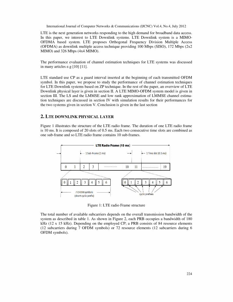
Figure 1 illustrates the structure of the LTE radio frame. The duration of one LTE radio frame
is 10 ms. It is composed of 20 slots of 0.5 ms. Each two consecutive time slots are combined as
one sub-frame and so LTE radio frame contains 10 sub-frames.
Figure 1: LTE radio Frame structure
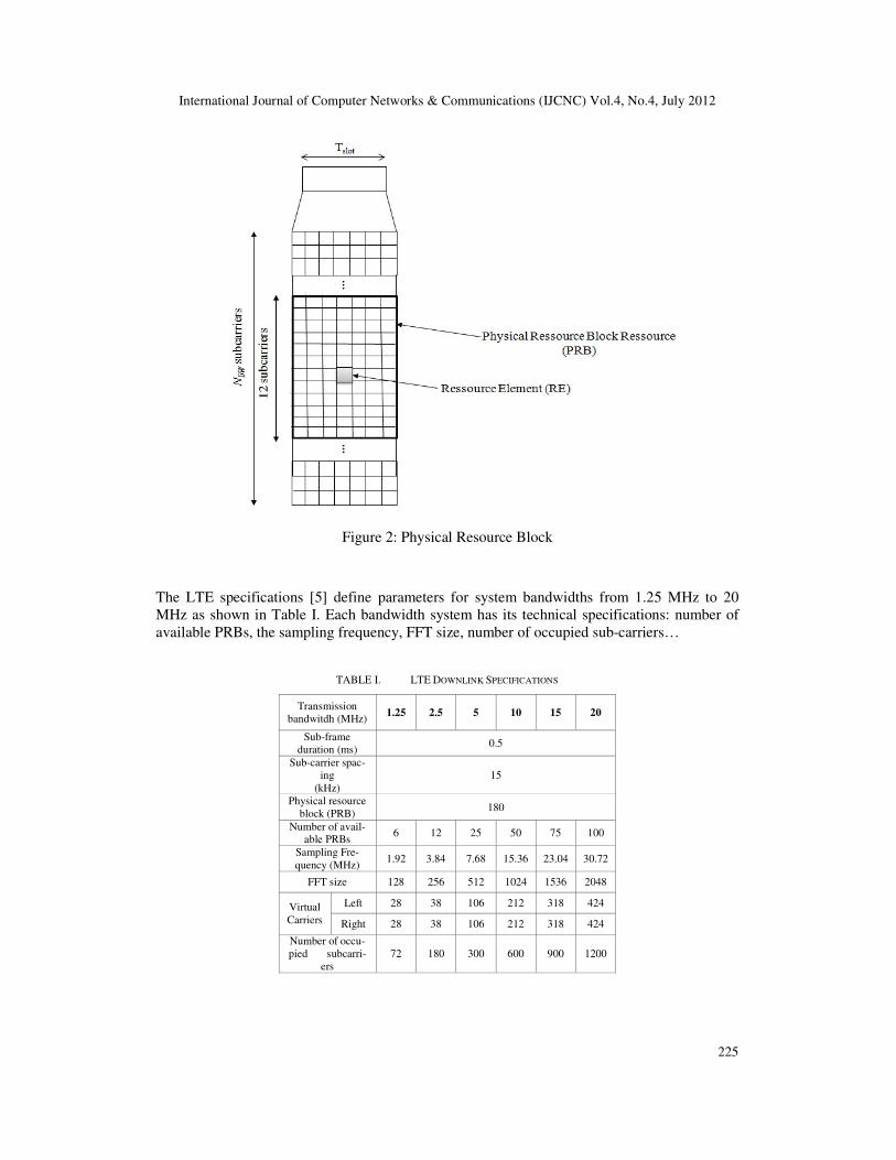
The total number of available subcarriers depends on the overall transmission bandwidth of the
system as described in table 1. As shown in Figure 2, each PRB occupies a bandwidth of 180
kHz (12 x 15 kHz). Depending on the employed CP; a PRB consists of 84 resource elements
(12 subcarriers during 7 OFDM symbols) or 72 resource elements (12 subcarriers during 6
OFDM symbols).
International Journal of Computer Networks & Communications (IJCNC) Vol.4, No.4, July 2012
225
Figure 2: Physical Resource Block
The LTE specifications [5] define parameters for system bandwidths from 1.25 MHz to 20
MHz as shown in Table I. Each bandwidth system has its technical specifications: number of
available PRBs, the sampling frequency, FFT size, number of occupied sub-carriers…
TABLE I. LTE DOWNLINK SPECIFICATIONS
Transmission
bandwitdh (MHz) 1.25 2.5 5 10 15 20
Sub-frame
duration (ms) 0.5
Sub-carrier spac-
ing
(kHz)
15
Physical resource
block (PRB) 180
Number of avail-able PRBs
6 12 25 50 75 100
Sampling Fre-
quency (MHz) 1.92 3.84 7.68 15.36 23.04 30.72
FFT size 128 256 512 1024 1536 2048
Virtual
Carriers
Left 28 38 106 212 318 424
Right 28 38 106 212 318 424
Number of occu-
pied subcarri-
ers
72 180 300 600 900 1200
International Journal of Computer Networks & Communications (IJCNC) Vol.4, No.4, July 2012
226
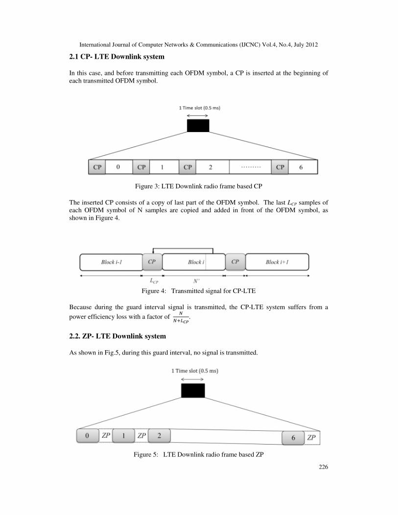
2.1 CP- LTE Downlink system
In this case, and before transmitting each OFDM symbol, a CP is inserted at the beginning of
each transmitted OFDM symbol.
Figure 3: LTE Downlink radio frame based CP
The inserted CP consists of a copy of last part of the OFDM symbol. The last LCP samples of
each OFDM symbol of N samples are copied and added in front of the OFDM symbol, as
shown in Figure 4.
Figure 4: Transmitted signal for CP-LTE
Because during the guard interval signal is transmitted, the CP-LTE system suffers from a
power efficiency loss with a factor of ������.
2.2. ZP- LTE Downlink system As shown in Fig.5, during this guard interval, no signal is transmitted.
Figure 5: LTE Downlink radio frame based ZP

International Journal of Computer Networks & Communications (IJCNC) Vol.4, No.4, July 2012
227
The inserted ZP consists of a serie of zeros inserted at the end of each transmitted known with
Zero Padding of the OFDM symbol. The last LCP samples of each OFDM symbol of N samples
are copied and added in front of the OFDM symbol, as shown in Figure 6.
Figure 6: LTE Downlink radio frame based ZP
Although the power efficiency loss is avoided in ZP-OFDM, the noise power will be enhanced
with a factor of ������ .
3. LTE DOWNLINK SYSTEM MODEL
The system model is given in Figure 7. LTE Downlink system is a MIMO-OFDMA based sys-
tem. We consider a MIMO–OFDM system with MT transmit and MR receive antennas.
Figure 7: LTE MIMO-OFDM Model
OFDMA is defined as the multiple access technique for LTE Downlink systems. OFDMA is a
multiple access scheme based on OFDM modulation technique. As shown in Fig. 3, we con-
sider an OFDM system with Nc carriers occupying the bandwidth. OFDM technique aims to
split the data stream to be transmitted onto narrowband orthogonal subcarriers by the means of
the Inverse Discrete Fourier Transform (IDFT) operation. In order to mitigate ISI and ICI, a
guard interval is inserted with the length of either LCP or LZP for respectively prefix cycling or
zero padding is inserted at the beginning of each transmitted OFDM symbol. The inserted
guard interval must be chosen to be equal or longer than the maximum excess delay of the
channel in order to completely suppress ISI and ICI.
International Journal of Computer Networks & Communications (IJCNC) Vol.4, No.4, July 2012
228
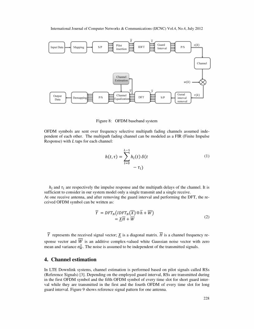
Figure 8: OFDM baseband system
OFDM symbols are sent over frequency selective multipath fading channels assumed inde-
pendent of each other. The multipath fading channel can be modeled as a FIR (Finite Impulse
Response) with L taps for each channel:
ℎ�, �� =�ℎ��������� ��
− ���
(1)
ℎ�and �� are respectively the impulse response and the multipath delays of the channel. It is
sufficient to consider in our system model only a single transmit and a single receive.
At one receive antenna, and after removing the guard interval and performing the DFT, the re-
ceived OFDM symbol can be written as:
� = �������������⊗ℎ + � = �! +
(2)
� represents the received signal vector; � is a diagonal matrix. ! is a channel frequency re-
sponse vector and is an additive complex-valued white Gaussian noise vector with zero
mean and variance"#$ . The noise is assumed to be independent of the transmitted signals.
4. Channel estimation
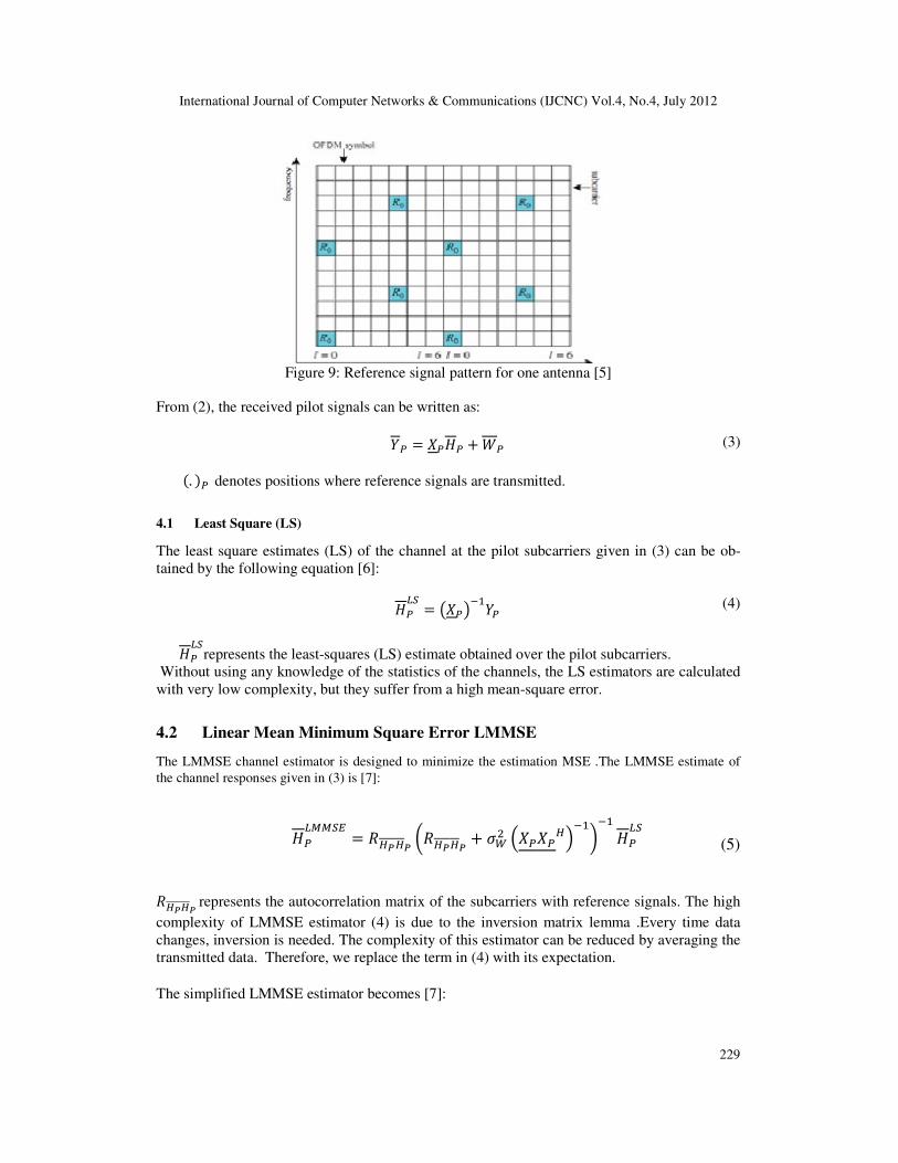
In LTE Downlink systems, channel estimation is performed based on pilot signals called RSs
(Reference Signals) [3]. Depending on the employed guard interval, RSs are transmitted during
in the first OFDM symbol and the fifth OFDM symbol of every time slot for short guard inter-
val while they are transmitted in the first and the fourth OFDM of every time slot for long
guard interval. Figure 9 shows reference signal pattern for one antenna.
International Journal of Computer Networks & Communications (IJCNC) Vol.4, No.4, July 2012
229
Figure 9: Reference signal pattern for one antenna [5]
From (2), the received pilot signals can be written as:
�% = �%!% + % (3)
�. �%denotes positions where reference signals are transmitted.
4.1 Least Square (LS)
The least square estimates (LS) of the channel at the pilot subcarriers given in (3) can be ob-
tained by the following equation [6]:
!%�' = ��%����% (4)
!%�'represents the least-squares (LS) estimate obtained over the pilot subcarriers.
Without using any knowledge of the statistics of the channels, the LS estimators are calculated
with very low complexity, but they suffer from a high mean-square error.
4.2 Linear Mean Minimum Square Error LMMSE
The LMMSE channel estimator is designed to minimize the estimation MSE .The LMMSE estimate of
the channel responses given in (3) is [7]:
!%�((') = *+�+� ,*+�+� + "#$ -�%�%+.��/��!%�'
(5)
*+�+�represents the autocorrelation matrix of the subcarriers with reference signals. The high
complexity of LMMSE estimator (4) is due to the inversion matrix lemma .Every time data
changes, inversion is needed. The complexity of this estimator can be reduced by averaging the
transmitted data. Therefore, we replace the term in (4) with its expectation.
The simplified LMMSE estimator becomes [7]:
International Journal of Computer Networks & Communications (IJCNC) Vol.4, No.4, July 2012
230
!%�((') = *+�+� ,*+�+� + 012* �%/��!%�'
(6)
where 0is scaling factor depending on the signal constellation (i.e for QPSK and for 16-
QAM). SNR is the average signal-to-noise ratio, and �% is the identity matrix.
4.3 Low rank approximation
The advantage of the LMMSE estimator is the avoidance of the matrix inversion but at the high
computational complexity. In order to improve the performance of channel estimation, the
LMMSE estimator can be approximated by using a low-rank simplified LMMSE estimator
achieved by the singular value decomposition.
The channel impulse response autocorrelation function matrix RHpHp, which is the channel im-
pulse response autocorrelation matrix which can be singular decomposed as [7]:
*+�+� = 3Λ3+ (7)
where U is the unitary matrix which consist of eigenvector, Λ=diag(λ1,λ2,…,λN) is a diagonal
matrix which contains the eigenvalues of *+�+� . The eigenvalues are ranged in descending
order. The simplified LMMSE of order p can be written as:
!%�5��(() = 3 6∆8 00 0:3+!%�' = 3∆3+!%�'
(8)
where ∆is a diagonal matrix defined as:
∆= Λ-Λ + ;'�<.��
= =>?@A B�B� + 012* ,B$B$ + 012* ,… ,
B�B� + 012*D
(9)
5. SIMULATION RESULTS
Simulation studies are conducted to investigate the performance of channel estimation tech-
niques for CP-LTE and ZP-LTE Downlink systems. Simulations results are based on LTE-5
MHz Downlink system with 2 transmit and 2 receive antennas. As cited in Table1, the number
of used subcarriers is 300. The length of the guard interval is set to 16. The transmitted signals
are quadrature phase-shift keying (QPSK) modulated.100 radio frames are sent through a fre-
quency-selective channel. The frequency-selective fading channel responses are randomly gen-
erated with a Rayleigh probability distribution. Table 2 gives a summary of simulation parame-
ters.
International Journal of Computer Networks & Communications (IJCNC) Vol.4, No.4, July 2012
231
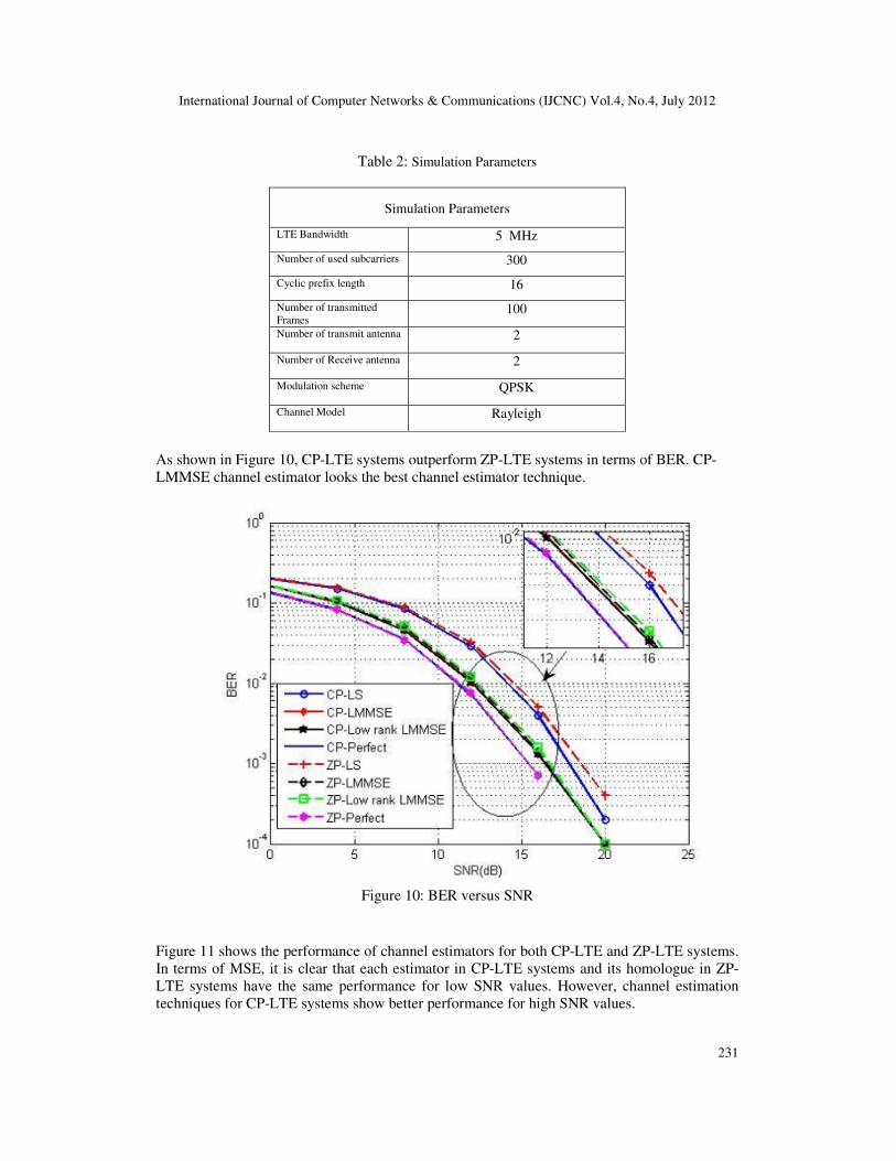
Table 2: Simulation Parameters
Simulation Parameters
LTE Bandwidth 5 MHz
Number of used subcarriers 300
Cyclic prefix length 16
Number of transmitted
Frames 100
Number of transmit antenna 2
Number of Receive antenna 2
Modulation scheme QPSK
Channel Model Rayleigh
As shown in Figure 10, CP-LTE systems outperform ZP-LTE systems in terms of BER. CP-
LMMSE channel estimator looks the best channel estimator technique.
Figure 10: BER versus SNR
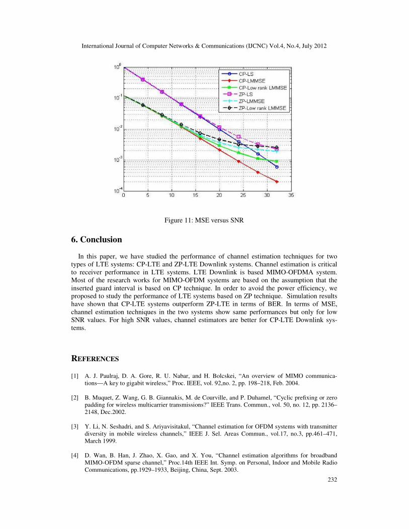
Figure 11 shows the performance of channel estimators for both CP-LTE and ZP-LTE systems.
In terms of MSE, it is clear that each estimator in CP-LTE systems and its homologue in ZP-
LTE systems have the same performance for low SNR values. However, channel estimation
techniques for CP-LTE systems show better performance for high SNR values.
International Journal of Computer Networks & Communications (IJCNC) Vol.4, No.4, July 2012
232
Figure 11: MSE versus SNR
6. Conclusion
In this paper, we have studied the performance of channel estimation techniques for two
types of LTE systems: CP-LTE and ZP-LTE Downlink systems. Channel estimation is critical
to receiver performance in LTE systems. LTE Downlink is based MIMO-OFDMA system.
Most of the research works for MIMO-OFDM systems are based on the assumption that the
inserted guard interval is based on CP technique. In order to avoid the power efficiency, we
proposed to study the performance of LTE systems based on ZP technique. Simulation results
have shown that CP-LTE systems outperform ZP-LTE in terms of BER. In terms of MSE,
channel estimation techniques in the two systems show same performances but only for low
SNR values. For high SNR values, channel estimators are better for CP-LTE Downlink sys-
tems.
REFERENCES
[1] A. J. Paulraj, D. A. Gore, R. U. Nabar, and H. Bolcskei, “An overview of MIMO communica-
tions—A key to gigabit wireless,” Proc. IEEE, vol. 92,no. 2, pp. 198–218, Feb. 2004.
[2] B. Muquet, Z. Wang, G. B. Giannakis, M. de Courville, and P. Duhamel, “Cyclic prefixing or zero
padding for wireless multicarrier transmissions?” IEEE Trans. Commun., vol. 50, no. 12, pp. 2136–
2148, Dec.2002.
[3] Y. Li, N. Seshadri, and S. Ariyavisitakul, “Channel estimation for OFDM systems with transmitter
diversity in mobile wireless channels,” IEEE J. Sel. Areas Commun., vol.17, no.3, pp.461–471,
March 1999.
[4] D. Wan, B. Han, J. Zhao, X. Gao, and X. You, “Channel estimation algorithms for broadband
MIMO-OFDM sparse channel,” Proc.14th IEEE Int. Symp. on Personal, Indoor and Mobile Radio
Communications, pp.1929–1933, Beijing, China, Sept. 2003.
International Journal of Computer Networks & Communications (IJCNC) Vol.4, No.4, July 2012
233
[5] 3GPP, “Evolved Universal Terrestrial Radio Access (E-UTRA); Physical channels and modula-
tion,” TS 36.211, 3rd Generation Partnership Project (3GPP), Sept. 2008.
[6] J.-J. van de Beek, O. Edfors, M. Sandell, S. K. Wilson, and P. O. Borjesson, “On channel estima-
tion in OFDM systems,” in Proc. IEEE 45th Vehicular Technology Conf., Chicago, IL, Jul. 1995,
pp. 815-819.
[7] O. Edfors, M. Sandell, J.-J. van de Beek, S. K. Wilson and P. O. Borjesson, “OFDM channel esti-
mation by singular value decomposition,”in Proc. IEEE 46th Vehicular Technology Conference,
Atlanta, GA, USA,Apr. 1996, pp. 923-927.
[8] S. D. Ma and T. S. Ng, “Time domain signal detection based on second-order statistics for MIMO-
OFDM systems,” IEEE Trans.Signal Process. vol. 55, no. 3, pp. 1150–1158, Mar. 2007.
[9] S.D. Ma and T.S. Ng, “Semi-blind time-domain equalization for MIMO-OFDM systems”, IEEE
Transactions on Vehicular Technology, 57(4), 2219-2227, July, 2008.
[10] MM Rana “Channel estimation techniques and LTE Terminal implementation challenges” in Proc.
International Conference on Computer and Information Technology pp. 545-549 December 2010
[11] M. Simko, D. Wu, C. Mehlführer, J. Eilert, D. Liu “Implementation Aspects of Channel Estimation
for 3GPP LTE Terminals” in Proc. Proc. European Wireless 2011, Vienna, April, 2011.
[12] A. Khlifi and R. Bouallegue, “Performance Analysis of LS and LMMSE channel estimation tech-
niques for LTE Downlink Systems” International Journal of Wireless & Mobile Networks
(IJWMN) Vol. 3, No. 5, October 2011.
Authors
Abdelhakim KHLIFI was born in Düsseldorf, Germany, on January 07, 1984.
He graduated in Telecommunications Engineering, from National Engineering
School of Gabès in Tunisia, July 2007.In June 2009, he received the master’s de-
gree of research in communication systems of the School of Engineering of Tunis
ENIT. Currently he is a Ph.D student at the National School of Engineering of
Tunis. His research spans radio channel estimation in LTE MIMO-OFDM sys-
tems.
Ridha BOUALLEGUE is Professor at the National Engineering School of Tunis,
Tunisia (ENIT). He practices at the Superior School of communication of Tunis
(Sup’Com). He is founding in 2005 and Director of the Research Unit "Telecom-
munications Systems: 6’Tel@Sup’ComˇT. He is founding in 2005, and Director of
the National Engineering School of Sousse. He received his PhD in 1998 then
HDR in 2003. His research and fundamental development, focus on the physical
layer of telecommunication systems in particular on digital communications sys-
tems, MIMO, OFDM, CDMA, UWB, WiMAX, LTE, has published 2 book chap-
ters, 75 articles in refereed conference lectures and 15 journal articles (2009).

Copyright of International Journal of Computer Networks & Communications is the property of Academy &
Industry Research Collaboration Center and its content may not be copied or emailed to multiple sites or posted
to a listserv without the copyright holder's express written permission. However, users may print, download, or
email articles for individual use.
Recommended