EUTRA/LTEDigital Standard forR&S®Signal GeneratorsOperating ManualEUTRA/LTE, LTE Rel. 9, LTE closedloop BS Test, LTE Logfile Generation,LTE-A Rel.10
Oper
ating
Man
ual
(;ÕÁÛ<)1171.5177.12 ─ 21
Test
& Me
asur
emen
t
This document describes the following software options:
● R&S®AMU-K55/-K255/-K69/-K81/-K84/-K284/-K85/-K2851402.9405.02, 1402.9457.02, 1403.0501.02, 1403.0553.02, 1403.0818.02, 1403.0853.02,1403.0830.02, 1403.0876.02
● R&S®SMATE-K55/-K69/-K81/-K84/-K851404.7851.02, 1403.0501.02, 1404.8612.02, 1404.8829.02, 1404.8841.02
● R&S®SMBV-K55/-K255/-K84/-K284/-K85/-K2851407.9203.xx, 1415.8360.02, 1415.8602.xx, 1415.8625.02, 1415.8619.xx, 1415.8631.02
● R&S®SMJ-K55/-K255/-K69/-K81/-K84/-K284/-K85/-K2851409.2206.02, 1409.2258.02, 1403.0501.02, 1409.3054.02, 1409.3360.02, 1409.3402.02,1409.3383.02, 1409.3425.02
● R&S®SMU-K55/-K255/-K69/-K81/-K84/-K284/-K85/-K2851408.7310.02, 1408.7362.02, 1403.0501.02, 1408.8169.02, 1408.8475.02, 1408.8517.02,1408.8498.02, 1408.8530.02
● R&S®SMW-K255/-K284/-K2851413.5235.02, 1413.5535.02, 1413.5587.02
● R&S®AFQ-K255/-K284/-K2851401.5906.02, 1415.0253.02, 1415.0276.02
● R&S®SFU-K2552115.2366.02
© 2013 Rohde & Schwarz GmbH & Co. KGMühldorfstr. 15, 81671 München, GermanyPhone: +49 89 41 29 - 0Fax: +49 89 41 29 12 164E-mail: [email protected]: www.rohde-schwarz.comSubject to change – Data without tolerance limits is not binding.R&S® is a registered trademark of Rohde & Schwarz GmbH & Co. KG.Trade names are trademarks of the owners.
The following abbreviations are used throughout this manual: R&S®AMU200A is abbreviated as R&S AMU, R&S®SMATE200A isabbreviated as R&S SMATE, R&S®SMBV100A is abbreviated as R&S SMBV, R&S®SMJ100A is abbreviated as R&S SMJ,R&S®SMU200A is abbreviated as R&S SMU, R&S®SMW200A is abbreviated as R&S SMW, R&S®WinIQSIM2TM is abbreviated asR&S WinIQSIM2
ContentsEUTRA/LTE
3Operating Manual 1171.5177.12 ─ 21
Contents1 Preface.................................................................................................. 11
1.1 Documentation Overview........................................................................................... 11
1.2 Typographical Conventions.......................................................................................12
2 Preamble...............................................................................................13
3 Introduction to the EUTRA/LTE Technology..................................... 143.1 LTE Downlink Transmission Scheme....................................................................... 14
3.1.1 OFDMA Parameterization............................................................................................. 15
3.1.1.1 Frame structure type 1 (FDD)....................................................................................... 15
3.1.1.2 Frame structure type 2 (TDD)....................................................................................... 16
3.1.2 Downlink Resource Grid............................................................................................... 17
3.1.3 Downlink Data Transmission.........................................................................................19
3.1.4 Downlink Control Information Transmission..................................................................19
3.1.5 Downlink Reference Signal Structure and Cell Search.................................................20
3.1.5.1 Cell-specific downlink reference signals....................................................................... 21
3.1.5.2 MBSFN reference signals............................................................................................. 23
3.1.5.3 UE-specific reference signal (DM-RS).......................................................................... 24
3.1.5.4 Positioning reference signals........................................................................................ 25
3.1.5.5 CSI reference signals....................................................................................................26
3.1.6 Downlink Physical Layer Procedures............................................................................27
3.2 LTE Uplink Transmission Scheme............................................................................ 27
3.2.1 SC-FDMA Parameterization..........................................................................................28
3.2.2 Uplink Data Transmission............................................................................................. 29
3.2.3 Uplink Control Information Transmission...................................................................... 29
3.2.4 Uplink Reference Signal Structure................................................................................ 31
3.2.5 Uplink Physical Layer Procedures................................................................................ 31
3.3 LTE MIMO Concepts................................................................................................... 34
3.3.1 Downlink MIMO.............................................................................................................34
3.3.1.1 Spatial Multiplexing....................................................................................................... 34
3.3.1.2 Transmit Diversity......................................................................................................... 37
3.3.1.3 Beamforming.................................................................................................................37
3.3.2 Uplink MIMO................................................................................................................. 37
ContentsEUTRA/LTE
4Operating Manual 1171.5177.12 ─ 21
3.4 LTE MBMS Concepts.................................................................................................. 37
3.5 LTE-Advanced Introduction....................................................................................... 38
3.5.1 Carrier Aggregation.......................................................................................................38
3.5.2 Enhanced Uplink SC-FDMA..........................................................................................40
4 EUTRA/LTE Parameterization............................................................. 414.1 OFDMA Parameterization........................................................................................... 41
4.2 Reference Signals....................................................................................................... 41
4.3 Synchronization Signal (SYNC)................................................................................. 42
4.4 Physical Broadcast Channel (PBCH)........................................................................ 43
4.5 Physical Control Format Indicator Channel (PCFICH)............................................ 43
4.6 Physical Hybrid ARQ Indicator Channel (PHICH).................................................... 43
4.7 Physical Downlink Control Channel (PDCCH)......................................................... 44
4.8 Physical Multicast Channel (PMCH)..........................................................................44
4.9 Data Allocations.......................................................................................................... 44
4.10 Modulation Mapping................................................................................................... 45
4.11 MIMO............................................................................................................................ 45
4.12 SC-FDMA Parameterization........................................................................................46
4.13 Demodulation Reference Signal (DRS)..................................................................... 46
4.14 Sounding Reference Signal (SRS).............................................................................46
4.15 Physical Uplink Control Channel (PUCCH).............................................................. 47
4.16 Physical Random Access Channel (PRACH)........................................................... 47
4.17 Data Allocation............................................................................................................ 47
4.18 Modulation Mapping................................................................................................... 48
5 R&S Signal Generator Specific Information...................................... 495.1 Conflict Handling........................................................................................................ 49
5.1.1 Downlink........................................................................................................................49
5.1.2 Uplink............................................................................................................................ 50
5.1.3 DCI Conflict Handling....................................................................................................51
5.2 Subframes Handling................................................................................................... 53
5.2.1 Copy/Paste Subframe................................................................................................... 53
5.2.2 Number of Configurable Subframes..............................................................................54
5.2.3 Four Configurable Frames in Uplink and Downlink Direction........................................54
5.2.3.1 Uplink Direction............................................................................................................. 54
ContentsEUTRA/LTE
5Operating Manual 1171.5177.12 ─ 21
5.2.3.2 Downlink Direction........................................................................................................ 56
5.3 Power Setting.............................................................................................................. 57
5.3.1 General Power Settings................................................................................................ 57
5.3.2 Downlink Power Settings.............................................................................................. 58
5.3.3 Uplink Power Settings................................................................................................... 59
6 Realtime Feedback for Closed Loop BS Tests..................................616.1 Exemplary Testing Scenario...................................................................................... 61
6.2 Feedback Modes......................................................................................................... 62
6.2.1 Binary Mode.................................................................................................................. 63
6.2.2 Serial Mode................................................................................................................... 63
6.2.3 Serial 3x8 Mode............................................................................................................ 63
6.2.4 Structure of a serial and 3x8 serial feedback command............................................... 64
6.3 Timing Aspects........................................................................................................... 66
6.3.1 Parameterization of the feedback timing.......................................................................66
6.3.1.1 Timing for binary mode with 3GPP Distance Mode, serial or serial 3x8 mode............. 66
6.3.1.2 Maximum number of serial feedback commands..........................................................67
6.3.1.3 Timing for binary mode with Direct Response Distance Mode..................................... 67
6.3.2 Uplink Timing................................................................................................................ 68
6.3.2.1 General timing rules...................................................................................................... 70
6.4 Avoiding Synchronization Problems........................................................................ 70
6.5 Limitation..................................................................................................................... 72
7 EUTRA/LTE User Interface.................................................................. 737.1 Main Dialog for EUTRA/LTE Signals......................................................................... 73
7.2 LTE Logfile Generation...............................................................................................79
7.2.1 Signal Processing Chains and Logging Points............................................................. 79
7.2.2 Output Files...................................................................................................................82
7.2.2.1 File Names.................................................................................................................... 82
7.2.2.2 Extended Logfiles Contents.......................................................................................... 85
Extended DCI Logfile.................................................................................................... 86
Extended UCI Logfile.................................................................................................... 88
7.2.3 Working with the Logfile Generation Functionality........................................................ 89
7.2.4 Logfile Generation Settings...........................................................................................90
7.3 Test Setups/Models.................................................................................................... 93
ContentsEUTRA/LTE
6Operating Manual 1171.5177.12 ─ 21
7.4 General DL Settings / General TDD DL Settings...................................................... 94
7.4.1 DL Carrier Aggregation Configuration...........................................................................96
7.4.1.1 About the Carrier Aggregation...................................................................................... 97
7.4.1.2 How to Enable Carrier Aggregation and Cross-Carrier Scheduling.............................. 98
7.4.1.3 Carrier Aggregation Settings.........................................................................................99
7.4.2 MBSFN Settings..........................................................................................................102
7.4.3 Physical Settings.........................................................................................................114
7.4.4 TDD Frame Structure Settings....................................................................................116
7.4.5 Scheduling Settings.................................................................................................... 117
7.4.6 MIMO.......................................................................................................................... 118
7.4.7 Cell Specific Settings.................................................................................................. 120
7.4.8 Downlink Reference Signal Structure......................................................................... 123
7.4.9 Synchronization Signal Settings..................................................................................124
7.4.10 Positioning Reference Signal (PRS) Settings............................................................. 124
7.4.11 CSI Settings................................................................................................................ 129
7.5 DL Frame Configuration Settings............................................................................133
7.5.1 General Frame Configuration Settings........................................................................134
7.5.2 Subframe Configuration Settings................................................................................ 135
7.5.3 DL Resource Allocation Table ....................................................................................136
7.6 Enhanced PBCH, PDSCH and PMCH Settings....................................................... 143
7.6.1 Allocation Settings.......................................................................................................144
7.6.2 Precoding Settings...................................................................................................... 144
7.6.3 CSI-RS Settings.......................................................................................................... 148
7.6.4 Scrambling Settings.................................................................................................... 149
7.6.5 Channel Coding Settings............................................................................................ 150
7.7 Enhanced PCFICH, PHICH and PDCCH Channel Configuration...........................152
7.7.1 General PCFICH/PHICH/PDCCH Configuration and Precoding Settings.................. 153
7.7.2 PCFICH Settings.........................................................................................................154
7.7.3 PHICH Settings........................................................................................................... 155
7.7.4 PDCCH Settings......................................................................................................... 157
7.7.5 PDCCH Format Variable.............................................................................................160
7.7.6 DCI Format Configuration........................................................................................... 166
7.8 User Configuration Settings.................................................................................... 177
ContentsEUTRA/LTE
7Operating Manual 1171.5177.12 ─ 21
7.9 Antenna Port Mapping Settings...............................................................................181
7.10 SPS Configuration Settings..................................................................................... 185
7.11 Dummy Data Configuration Settings...................................................................... 190
7.12 OFDMA Timeplan...................................................................................................... 192
7.13 General UL Settings..................................................................................................193
7.13.1 Physical Settings.........................................................................................................194
7.13.2 TDD Frame Structure Settings....................................................................................196
7.13.3 Cell Specific Settings.................................................................................................. 197
7.13.4 UL Reference Signals................................................................................................. 198
7.13.5 PRACH Settings..........................................................................................................199
7.13.6 PUSCH Structure........................................................................................................ 201
7.13.7 PUCCH Structure........................................................................................................202
7.13.8 SRS Structure............................................................................................................. 204
7.14 UL Frame Configuration Settings............................................................................206
7.14.1 General Scheduling Configuration Settings................................................................ 206
7.14.2 Subframe Configuration.............................................................................................. 208
7.14.3 UL Allocation Table..................................................................................................... 209
7.15 User Equipment Configuration................................................................................ 213
7.15.1 Common Settings........................................................................................................216
7.15.2 FRC Configuration...................................................................................................... 218
7.15.3 Realtime Feedback Configuration Settings.................................................................220
7.15.4 HARQ Statistics.......................................................................................................... 225
7.15.5 Physical Uplink Shared Channel (PUSCH).................................................................226
7.15.6 Reference Signal Structure......................................................................................... 229
7.15.7 SRS Structure............................................................................................................. 231
7.15.8 PRACH Power Ramping............................................................................................. 237
7.15.9 PRACH Configuration................................................................................................. 237
7.16 Enhanced PUSCH Settings...................................................................................... 239
7.16.1 Common PUSCH Settings.......................................................................................... 240
7.16.2 Frequency Hopping.....................................................................................................241
7.16.3 Channel Coding / Multiplexing.................................................................................... 241
7.17 Enhanced PUCCH Settings...................................................................................... 244
7.17.1 Common Settings........................................................................................................245
ContentsEUTRA/LTE
8Operating Manual 1171.5177.12 ─ 21
7.17.2 Channel Coding / Multiplexing.................................................................................... 245
7.18 SC-FDMA Timeplan...................................................................................................248
7.19 TDD Timeplan............................................................................................................ 249
7.20 Filter/Clipping/Power Settings................................................................................. 251
7.20.1 Time Domain Windowing Settings.............................................................................. 251
7.20.2 Filter Settings.............................................................................................................. 252
7.20.3 Clipping Settings......................................................................................................... 256
7.20.4 Time Domain Windowing Settings.............................................................................. 257
7.20.5 Power Settings............................................................................................................ 257
7.21 Trigger/Marker/Clock Settings................................................................................. 259
7.21.1 Trigger In.....................................................................................................................260
7.21.2 Timing Configuration................................................................................................... 265
7.21.3 Marker Mode............................................................................................................... 266
7.21.4 Marker Delay...............................................................................................................267
7.21.5 Clock Settings............................................................................................................. 268
7.21.6 Global Settings............................................................................................................270
8 Test Case Wizard............................................................................... 2718.1 Introduction to Conformance Testing.....................................................................271
8.1.1 UE Conformance Testing............................................................................................271
8.1.2 BS Conformance Testing............................................................................................ 273
8.1.3 Repeater Conformance Testing.................................................................................. 273
8.2 Basic Configuration.................................................................................................. 273
8.3 Supported Test Cases.............................................................................................. 273
8.3.1 Generic Structure of the Description of the Implemented Test Cases........................ 275
8.4 Standard Test Setups............................................................................................... 276
8.4.1 Standard Test Setup - One Path.................................................................................276
8.4.2 Standard Test Setup - Two Paths............................................................................... 276
8.4.3 Test Setup - Diversity Measurements......................................................................... 277
8.4.4 Test Setup - Four Rx Antennas...................................................................................278
8.5 General Considerations............................................................................................279
8.6 User Interface............................................................................................................ 282
8.6.1 Test Case Settings......................................................................................................283
8.6.2 Instrument Settings..................................................................................................... 284
ContentsEUTRA/LTE
9Operating Manual 1171.5177.12 ─ 21
8.6.3 Wanted Signal and Cell Specific Settings................................................................... 286
8.6.4 Apply........................................................................................................................... 288
8.7 Transmitter Characteristics (TS 36.141, Chapter 6)...............................................289
8.7.1 Prior Considerations....................................................................................................289
8.7.2 Introduction to the Unwanted Emissions Tests........................................................... 289
8.7.3 Test Case 6.7: Transmitter Intermodulation................................................................291
8.8 Receiver Characteristics (TS 36.141, Chapter 7)....................................................297
8.8.1 Prior Considerations....................................................................................................297
8.8.2 General Workflow for Carrying Out a Receiver Test...................................................298
8.8.3 Interfering Signal Settings........................................................................................... 299
8.8.4 Test Case 7.2: Reference Sensitivity Level................................................................ 303
8.8.5 Test Case 7.3: Dynamic range....................................................................................305
8.8.6 Test Case 7.4: In-channel selectivity (ICS)................................................................. 308
8.8.7 Test Case 7.5A: Adjacent Channel Selectivity (ACS)................................................. 311
8.8.8 Test Case 7.5B: Narrow-band blocking...................................................................... 313
8.8.9 Test Case 7.6: Blocking.............................................................................................. 316
8.8.10 Test Case 7.8: Receiver intermodulation ................................................................... 320
8.9 Performance Requirements (TS 36.141, Chapter 8)...............................................324
8.9.1 Prior Considerations....................................................................................................324
8.9.2 Realtime Feedback Configuration, AWGN and Propagation Condition Settings........ 327
8.9.3 Test Case 8.2.1: PUSCH in multipath fading propagation conditions.........................328
8.9.4 Test Case 8.2.2: UL timing adjustment....................................................................... 332
8.9.5 Test Case 8.2.3: HARQ-ACK multiplexed on PUSCH................................................ 336
8.9.6 Test Case 8.2.4: High Speed Train conditions............................................................339
8.9.7 Test Case 8.3.1: ACK missed detection for single user PUCCH format 1a................342
8.9.8 Test Case 8.3.2: CQI performance requirements for PUCCH format 2...................... 345
8.9.9 Test Case 8.3.3: ACK missed detection for multi user PUCCH format 1a..................347
8.9.10 Test Case 8.3.4: ACK missed detection for PUCCH format 1b, channel selection.... 352
8.9.11 Test Case 8.3.5: ACK missed detection for PUCCH format 3.................................... 355
8.9.12 Test Case 8.3.6: NACK to ACK detection for PUCCH format 3..................................358
8.9.13 Test Case 8.3.9: CQI Performance for PUCCH format 2 with DTX detection............ 361
8.9.14 Test Case 8.4.1: PRACH false alarm probability and missed detection..................... 363
9 Remote-Control Commands............................................................. 368
ContentsEUTRA/LTE
10Operating Manual 1171.5177.12 ─ 21
9.1 Primary Commands.................................................................................................. 369
9.2 Filter/Clipping/Power Settings................................................................................. 374
9.2.1 Filter Settings.............................................................................................................. 374
9.2.2 Clipping Settings......................................................................................................... 381
9.2.3 Time Domain Windowing Settings.............................................................................. 382
9.2.4 Power Settings............................................................................................................ 383
9.3 Clock Settings........................................................................................................... 385
9.4 Timing Configuration................................................................................................388
9.5 Trigger Settings.........................................................................................................388
9.6 Marker Settings......................................................................................................... 397
9.7 General EUTRA/LTE Settings.................................................................................. 402
9.8 General EUTRA/LTE Downlink Settings................................................................. 403
9.9 General EUTRA/LTE Uplink Settings...................................................................... 417
9.10 DL Frame Configuration........................................................................................... 430
9.11 DL MBFSN Settings.................................................................................................. 440
9.12 DL Carrier Aggregation Settings............................................................................. 449
9.13 CSI-RS Settings.........................................................................................................453
9.14 Enhanced PBCH, PDSCH, PMCH Settings............................................................. 457
9.15 Enhanced PCFICH, PHICH and PDCCH Configuration..........................................465
9.16 UL Frame Configuration........................................................................................... 498
9.17 UL Enhanced Settings.............................................................................................. 504
9.18 Configure User.......................................................................................................... 513
9.19 Dummy Data Configuration......................................................................................519
9.20 SPS Configuration.................................................................................................... 521
9.21 User Equipment.........................................................................................................522
9.22 Realtime Feedback....................................................................................................539
9.23 LTE Logfiles Generation...........................................................................................545
9.24 Test Case Wizard Remote-Control Commands......................................................547
A References..........................................................................................566
List of Commands..............................................................................568
Index....................................................................................................580
PrefaceEUTRA/LTE
11Operating Manual 1171.5177.12 ─ 21
1 Preface
1.1 Documentation Overview
The user documentation for the R&S Signal Generator consists of the following parts:
● Online Help system on the instrument,● "Quick Start Guide" printed manual,● Documentation CD-ROM with:
– Online help system (*.chm) as a standalone help,– Operating Manuals for base unit and options,– Service Manual,– Data sheet and specifications,– Links to useful sites on the R&S internet.
Online Help
The Online Help is embedded in the instrument's firmware. It offers quick, context-sen-sitive access to the complete information needed for operation and programming. Theonline help contains help on operating the R&S Signal Generator and all availableoptions.
Quick Start Guide
The Quick Start Guide is delivered with the instrument in printed form and in PDF for-mat on the Documentation CD-ROM. It provides the information needed to set up andstart working with the instrument. Basic operations and an example of setup are descri-bed. The manual includes also general information, e.g., Safety Instructions.
Operating Manuals
The Operating Manuals are a supplement to the Quick Start Guide. Operating Manualsare provided for the base unit and each additional (software) option.
These manuals are available in PDF format - in printable form - on the DocumentationCD-ROM delivered with the instrument. In the Operating Manual for the base unit, allinstrument functions are described in detail. Furthermore, it provides an introduction toremote control and a complete description of the remote control commands with pro-gramming examples. Information on maintenance, instrument interfaces and errormessages is also given.
In the individual option manuals, the specific instrument functions of the option aredescribed in detail. For additional information on default settings and parameters, referto the data sheets. Basic information on operating the R&S Signal Generator is notincluded in the option manuals.
Documentation Overview
PrefaceEUTRA/LTE
12Operating Manual 1171.5177.12 ─ 21
Service Manual
The Service Manual is available in PDF format - in printable form - on the Documenta-tion CD-ROM delivered with the instrument. It describes how to check compliance withrated specifications, on instrument function, repair, troubleshooting and fault elimina-tion. It contains all information required for repairing the instrument by the replacementof modules.
This manual can also be orderd in printed form (see ordering information in the datasheet).
Release Notes
The release notes describe new and modified functions, eliminated problems, and lastminute changes to the documentation. The corresponding firmware version is indicatedon the title page of the release notes. The current release notes are provided in theInternet.
Web Helps
Web helps are provided for the base unit and each additional (software) option. Thecontent of the web helps correspond to the user manuals for the latest product ver-sions.
The web help is an additional file format that offers quick online access. They are notintended to be downloaded but rather to access the required information directly formthe R&S website.
Web helps are available at the R&S website, on the R&S Signal Generator productpage at the "Downloads > Web Help" area.
1.2 Typographical Conventions
The following text markers are used throughout this documentation:
Convention Description
"Graphical user interface ele-ments"
All names of graphical user interface elements on the screen, such asdialog boxes, menus, options, buttons, and softkeys are enclosed byquotation marks.
KEYS Key names are written in capital letters.
File names, commands,program code
File names, commands, coding samples and screen output are distin-guished by their font.
Input Input to be entered by the user is displayed in italics.
Links Links that you can click are displayed in blue font.
"References" References to other parts of the documentation are enclosed by quota-tion marks.
Typographical Conventions
PreambleEUTRA/LTE
13Operating Manual 1171.5177.12 ─ 21
2 PreambleAll supported features are in line with 3GPP Release 10, i.e. the following official 3GPPspecifications are implemented:● 3GPP TS 36.211, Version 10.6.0● 3GPP TS 36.212, Version 10.7.0● 3GPP TS 36.213, Version 10.8.0
Introduction to the EUTRA/LTE TechnologyEUTRA/LTE
14Operating Manual 1171.5177.12 ─ 21
3 Introduction to the EUTRA/LTE TechnologyThis section provieds an introduction to the EUTRA/LTE technology.
3.1 LTE Downlink Transmission Scheme
The downlink transmission scheme for E-UTRA FDD and TDD modes is based on con-ventional OFDM. In an OFDM system, the available spectrum is divided into multiplecarriers, called subcarriers, which are orthogonal to each other. Each of these subcarri-ers is independently modulated by a low rate data stream.
OFDM is used as well in WLAN, WiMAX and broadcast technologies like DVB. OFDMhas several benefits including its robustness against multipath fading and its efficientreceiver architecture.
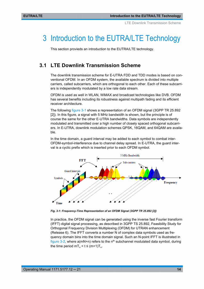
The following figure 3-1 shows a representation of an OFDM signal (3GPP TR 25.892[2]). In this figure, a signal with 5 MHz bandwidth is shown, but the principle is ofcourse the same for the other E-UTRA bandwidths. Data symbols are independentlymodulated and transmitted over a high number of closely spaced orthogonal subcarri-ers. In E-UTRA, downlink modulation schemes QPSK, 16QAM, and 64QAM are availa-ble.
In the time domain, a guard interval may be added to each symbol to combat inter-OFDM-symbol-interference due to channel delay spread. In E-UTRA, the guard inter-val is a cyclic prefix which is inserted prior to each OFDM symbol.
Fig. 3-1: Frequency-Time Representation of an OFDM Signal (3GPP TR 25.892 [2])
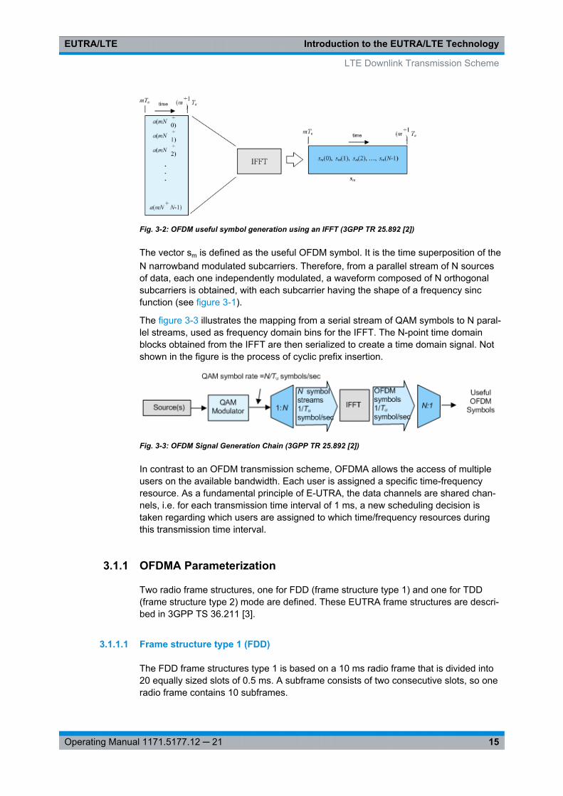
In practice, the OFDM signal can be generated using the inverse fast Fourier transform(IFFT) digital signal processing, as described in 3GPP TS 25.892, Feasibility Study forOrthogonal Frequency Division Multiplexing (OFDM) for UTRAN enhancement(Release 6). The IFFT converts a number N of complex data symbols used as fre-quency domain bins into the time domain signal. Such an N-point IFFT is illustrated infigure 3-2, where a(mN+n) refers to the nth subchannel modulated data symbol, duringthe time period mTu < t ≤ (m+1)Tu.
LTE Downlink Transmission Scheme
Introduction to the EUTRA/LTE TechnologyEUTRA/LTE
15Operating Manual 1171.5177.12 ─ 21
Fig. 3-2: OFDM useful symbol generation using an IFFT (3GPP TR 25.892 [2])
The vector sm is defined as the useful OFDM symbol. It is the time superposition of theN narrowband modulated subcarriers. Therefore, from a parallel stream of N sourcesof data, each one independently modulated, a waveform composed of N orthogonalsubcarriers is obtained, with each subcarrier having the shape of a frequency sincfunction (see figure 3-1).
The figure 3-3 illustrates the mapping from a serial stream of QAM symbols to N paral-lel streams, used as frequency domain bins for the IFFT. The N-point time domainblocks obtained from the IFFT are then serialized to create a time domain signal. Notshown in the figure is the process of cyclic prefix insertion.
Fig. 3-3: OFDM Signal Generation Chain (3GPP TR 25.892 [2])
In contrast to an OFDM transmission scheme, OFDMA allows the access of multipleusers on the available bandwidth. Each user is assigned a specific time-frequencyresource. As a fundamental principle of E-UTRA, the data channels are shared chan-nels, i.e. for each transmission time interval of 1 ms, a new scheduling decision istaken regarding which users are assigned to which time/frequency resources duringthis transmission time interval.
3.1.1 OFDMA Parameterization
Two radio frame structures, one for FDD (frame structure type 1) and one for TDD(frame structure type 2) mode are defined. These EUTRA frame structures are descri-bed in 3GPP TS 36.211 [3].
3.1.1.1 Frame structure type 1 (FDD)
The FDD frame structures type 1 is based on a 10 ms radio frame that is divided into20 equally sized slots of 0.5 ms. A subframe consists of two consecutive slots, so oneradio frame contains 10 subframes.
LTE Downlink Transmission Scheme
Introduction to the EUTRA/LTE TechnologyEUTRA/LTE
16Operating Manual 1171.5177.12 ─ 21
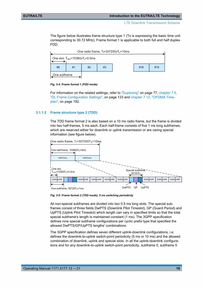
The figure below illustrates frame structure type 1 (Ts is expressing the basic time unitcorresponding to 30.72 MHz). Frame format 1 is applicable to both full and half duplexFDD.
Fig. 3-4: Frame format 1 (FDD mode)
For information on the related settings, refer to "Duplexing" on page 77, chapter 7.5,"DL Frame Configuration Settings", on page 133 and chapter 7.12, "OFDMA Time-plan", on page 192.
3.1.1.2 Frame structure type 2 (TDD)
The TDD frame format 2 is also based on a 10 ms radio frame, but the frame is dividedinto two half-frames, 5 ms each. Each half-frame consists of five 1 ms long subframes,which are reserved either for downlink or uplink transmission or are caring specialinformation (see figure below).
Fig. 3-5: Frame format 2 (TDD mode), 5 ms switching periodicity
All non-special subframes are divided into two 0.5 ms long slots. The special sub-frames consist of three fields DwPTS (Downlink Pilot Timeslot), GP (Guard Period) andUpPTS (Uplink Pilot Timeslot) which length can vary in specified limits so that the totalspecial subframe's length is maintained constant (1 ms). The 3GPP specificationdefines nine special subframe configurations per cyclic prefix type that specified theallowed DwPTS/GP/UpPTS lengths' combinations.
The 3GPP specification defines seven different uplink-downlink configurations, i.e.defines the downlink-to-uplink switch-point periodicity (5 ms or 10 ms) and the allowedcombination of downlink, uplink and special slots. In all the uplink-downlink configura-tions and for any downlink-to-uplink switch-point periodicity, subframe 0, subframe 5
LTE Downlink Transmission Scheme

Introduction to the EUTRA/LTE TechnologyEUTRA/LTE
17Operating Manual 1171.5177.12 ─ 21
and DwPTS are always reserved for downlink transmission and UpPTS and the sub-frame following the special subframe are always reserved for uplink transmission.
The table below shows the supported uplink-downlink configurations according to TS36.211 [3], where "D" denotes a subframe reserved for downlink transmission, "U"denotes a subframe reserved for uplink transmission, and "S" denotes the special sub-frame.
Fig. 3-6: Uplink-downlink configurations
For information on the related settings, refer to "Duplexing" on page 77, chap-ter 7.4.4, "TDD Frame Structure Settings", on page 116 and chapter 7.19, "TDD Time-plan", on page 249.
3.1.2 Downlink Resource Grid
The figure 3-7 shows the structure of the downlink resource grid for the duration of onedownlink slot. The available downlink bandwidth consists of subcarriers with aspacing of Δf = 15 kHz. In the case of multi-cell MBMS transmission, a subcarrierspacing of Δf = 7.5 kHz is also possible. can vary in order to allow for scalablebandwidth operation up to 20 MHz. Initially, the bandwidths for LTE were explicitlydefined within layer 1 specifications. Later on a bandwidth agnostic layer 1 was intro-duced, with for the different bandwidths to be specified by 3GPP RAN4 to meetperformance requirements, e.g. for out-of-band emission requirements and regulatoryemission limits.
LTE Downlink Transmission Scheme
Introduction to the EUTRA/LTE TechnologyEUTRA/LTE
18Operating Manual 1171.5177.12 ─ 21
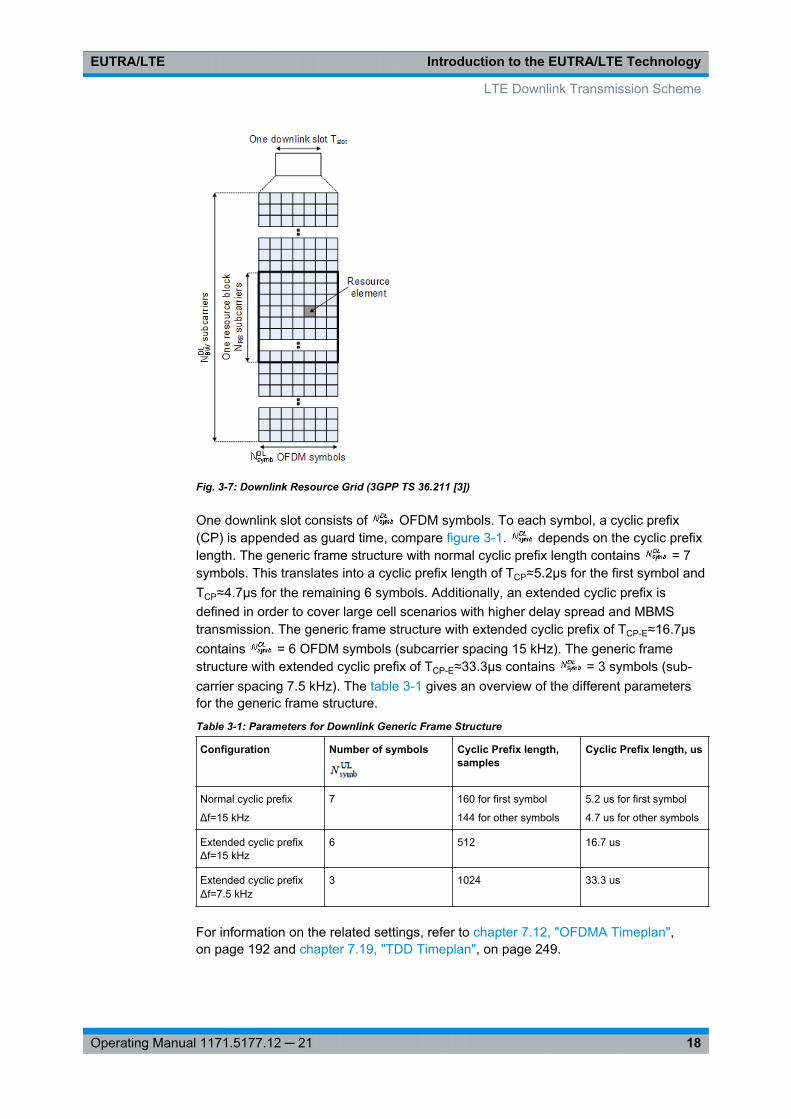
Fig. 3-7: Downlink Resource Grid (3GPP TS 36.211 [3])
One downlink slot consists of OFDM symbols. To each symbol, a cyclic prefix(CP) is appended as guard time, compare figure 3-1. depends on the cyclic prefixlength. The generic frame structure with normal cyclic prefix length contains = 7symbols. This translates into a cyclic prefix length of TCP≈5.2μs for the first symbol andTCP≈4.7μs for the remaining 6 symbols. Additionally, an extended cyclic prefix isdefined in order to cover large cell scenarios with higher delay spread and MBMStransmission. The generic frame structure with extended cyclic prefix of TCP-E≈16.7μscontains = 6 OFDM symbols (subcarrier spacing 15 kHz). The generic framestructure with extended cyclic prefix of TCP-E≈33.3μs contains = 3 symbols (sub-carrier spacing 7.5 kHz). The table 3-1 gives an overview of the different parametersfor the generic frame structure.
Table 3-1: Parameters for Downlink Generic Frame Structure
Configuration Number of symbols Cyclic Prefix length,samples
Cyclic Prefix length, us
Normal cyclic prefix
Δf=15 kHz
7 160 for first symbol
144 for other symbols
5.2 us for first symbol
4.7 us for other symbols
Extended cyclic prefixΔf=15 kHz
6 512 16.7 us
Extended cyclic prefixΔf=7.5 kHz
3 1024 33.3 us
For information on the related settings, refer to chapter 7.12, "OFDMA Timeplan",on page 192 and chapter 7.19, "TDD Timeplan", on page 249.
LTE Downlink Transmission Scheme
Introduction to the EUTRA/LTE TechnologyEUTRA/LTE
19Operating Manual 1171.5177.12 ─ 21
3.1.3 Downlink Data Transmission
Data is allocated to the UEs in terms of resource blocks. A physical resource blockconsists of 12 (24) consecutive subcarriers in the frequency domain for the Δf=15 kHz(Δf=7.5 kHz) case. In the time domain, a physical resource block consists of DL Nsymb
consecutive OFDM symbols, see figure 3-7. NDLsymb is equal to the number of OFDM
symbols in a slot. The resource block size is the same for all bandwidths, therefore thenumber of available physical resource blocks depends on the bandwidth. Dependingon the required data rate, each UE can be assigned one or more resource blocks ineach transmission time interval of 1 ms. The scheduling decision is done in the basestation (eNodeB). The user data is carried on the physical downlink shared channel(PDSCH).
For information on the related settings, refer to chapter 7.6, "Enhanced PBCH, PDSCHand PMCH Settings", on page 143.
3.1.4 Downlink Control Information Transmission
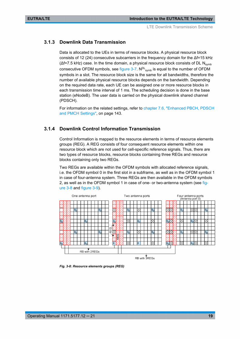
Control Information is mapped to the resource elements in terms of resource elementsgroups (REG). A REG consists of four consequent resource elements within oneresource block which are not used for cell-specific reference signals. Thus, there aretwo types of resource blocks, resource blocks containing three REGs and resourceblocks containing only two REGs.
Two REGs are available within the OFDM symbols with allocated reference signals,i.e. the OFDM symbol 0 in the first slot in a subframe, as well as in the OFDM symbol 1in case of four-antenna system. Three REGs are then available in the OFDM symbols2, as well as in the OFDM symbol 1 in case of one- or two-antenna system (see fig-ure 3-8 and figure 3-9).
Fig. 3-8: Resource elements groups (REG)
LTE Downlink Transmission Scheme
Introduction to the EUTRA/LTE TechnologyEUTRA/LTE
20Operating Manual 1171.5177.12 ─ 21
Three physical DL channels are carrying the control information: the Physical ControlFormat Indicator Channel (PCFICH), the Physical Hybrid ARQ Indicator Channel(PHICH) and the Physical Downlink Control Channel (PDCCH).● The PCFICH carries the information about the number of OFDM Symbols used for
transmission of PDCCH in a subframe and is mapped to four REGs within the firstOFDM Symbol.
● The PHICH carries the HARQ ACK/NACK messages and is transmitted in terms ofPHICH groups. A PHICH group uses three REGs. For normal CP, a PHICH groupconsists of up to eight ACK/NACK messages. Four ACK/NACK messages are car-ried by one PHICH group if an extended CP is used.For frame format 1 and non-MBSFN transmission, the PHICH can be transmittedover only the first OFDM symbol (this is the so called normal PHICH duration) or incase of extended PHICH duration, over the first three OFDM symbols.
● Downlink control signaling on the Physical Downlink Control Channel (PDCCH) isused to convey the scheduling decisions to individual UEs. The PDCCH is locatedin the first OFDM symbols of a slot.The maximum number of OFDM symbols used for the transmission of a PDCCH isdetermined by the number of RB used, i.e. for channel bandwidth with less than orequal to 10 RBs, four OFDM symbols are necessary (OFDM symbol 0...3) andrespectively for channel bandwidths greater than 10 RBs three OFDM symbols aresufficient (OFDM symbol 0...2).The minimum number of OFDM symbols used for the transmission of a PDCCH isdetermined by the PHICH duration and the channel bandwidth.The PDCCH is mapped to the REGs not used for PHICH and PCFICH and trans-mitted on one or several control channel elements (CCEs), where a CCE corre-sponds to 9 REGs.
For information on the related settings, refer to "PHICH Duration" on page 122 andchapter 7.7, "Enhanced PCFICH, PHICH and PDCCH Channel Configuration",on page 152.
3.1.5 Downlink Reference Signal Structure and Cell Search
The downlink reference signal structure is important for cell search, channel estimationand neighbor cell monitoring.
For the LTE downlink, four types of reference signals are defined:● Cell-specific downlink reference signals
The cell-specific reference signal are common signals in a cell, that are intendedfor all UE within this cell.
● chapter 3.1.5.2, "MBSFN reference signals", on page 23These reference signals are used for channel estimation and demodulation of sig-nals transmitted by means of MBSFN.
● UE-specific reference signal (DM-RS)These reference signals are intended for a specific user.
● chapter 3.1.5.4, "Positioning reference signals", on page 25● chapter 3.1.5.5, "CSI reference signals", on page 26
LTE Downlink Transmission Scheme
Introduction to the EUTRA/LTE TechnologyEUTRA/LTE
21Operating Manual 1171.5177.12 ─ 21
These reference signals are intended channel quality measurements and fre-quency deppendent scheduling.
For information on the related settings, refer to:● chapter 7.4.8, "Downlink Reference Signal Structure", on page 123● chapter 7.4.10, "Positioning Reference Signal (PRS) Settings", on page 124● chapter 7.4.11, "CSI Settings", on page 129.
3.1.5.1 Cell-specific downlink reference signals
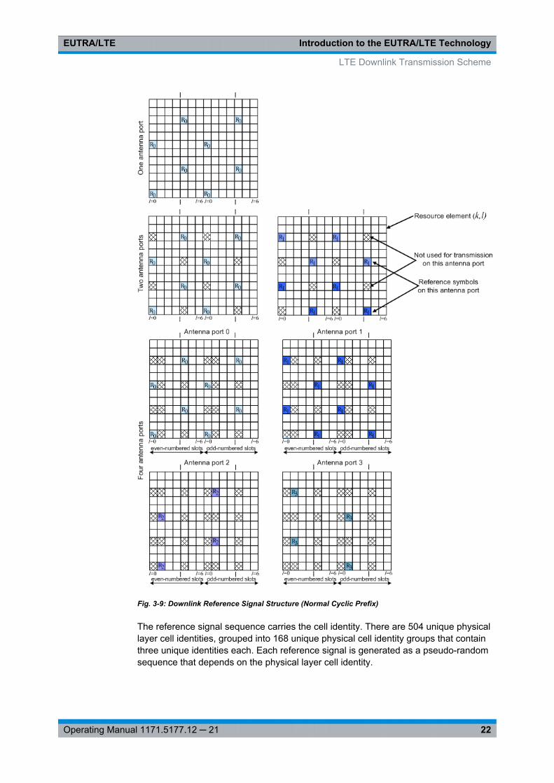
The figure 3-9 shows the principle of the downlink reference signal structure for one-antenna, two-antenna, and four-antenna transmission (antenna ports 0 .. 3). Specificpredefined resource elements in the time-frequency domain carry the reference signalsequence. Besides first reference symbols, there may be a need for second referencesymbols. The different colors in the figure represent the sequences transmitted from upto four transmit antennas.
LTE Downlink Transmission Scheme
Introduction to the EUTRA/LTE TechnologyEUTRA/LTE
22Operating Manual 1171.5177.12 ─ 21
Fig. 3-9: Downlink Reference Signal Structure (Normal Cyclic Prefix)
The reference signal sequence carries the cell identity. There are 504 unique physicallayer cell identities, grouped into 168 unique physical cell identity groups that containthree unique identities each. Each reference signal is generated as a pseudo-randomsequence that depends on the physical layer cell identity.
LTE Downlink Transmission Scheme
Introduction to the EUTRA/LTE TechnologyEUTRA/LTE
23Operating Manual 1171.5177.12 ─ 21
Frequency hopping can be applied to the downlink reference signals. The frequencyhopping pattern has a period of one frame (10 ms).
During cell search, different types of information need to be identified by the handset:symbol and radio frame timing, frequency, cell identification, overall transmission band-width, antenna configuration, and cyclic prefix length.
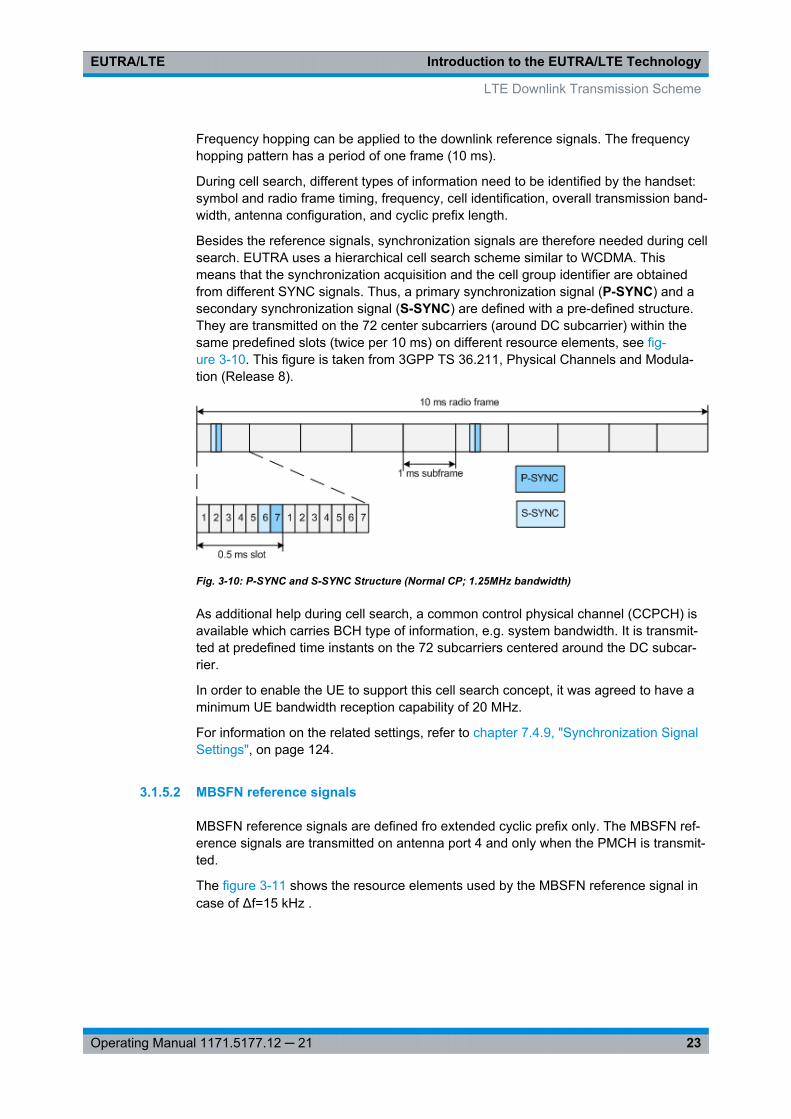
Besides the reference signals, synchronization signals are therefore needed during cellsearch. EUTRA uses a hierarchical cell search scheme similar to WCDMA. Thismeans that the synchronization acquisition and the cell group identifier are obtainedfrom different SYNC signals. Thus, a primary synchronization signal (P-SYNC) and asecondary synchronization signal (S-SYNC) are defined with a pre-defined structure.They are transmitted on the 72 center subcarriers (around DC subcarrier) within thesame predefined slots (twice per 10 ms) on different resource elements, see fig-ure 3-10. This figure is taken from 3GPP TS 36.211, Physical Channels and Modula-tion (Release 8).
Fig. 3-10: P-SYNC and S-SYNC Structure (Normal CP; 1.25MHz bandwidth)
As additional help during cell search, a common control physical channel (CCPCH) isavailable which carries BCH type of information, e.g. system bandwidth. It is transmit-ted at predefined time instants on the 72 subcarriers centered around the DC subcar-rier.
In order to enable the UE to support this cell search concept, it was agreed to have aminimum UE bandwidth reception capability of 20 MHz.
For information on the related settings, refer to chapter 7.4.9, "Synchronization SignalSettings", on page 124.
3.1.5.2 MBSFN reference signals
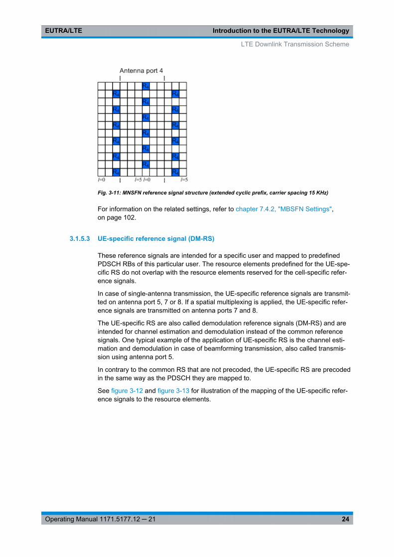
MBSFN reference signals are defined fro extended cyclic prefix only. The MBSFN ref-erence signals are transmitted on antenna port 4 and only when the PMCH is transmit-ted.
The figure 3-11 shows the resource elements used by the MBSFN reference signal incase of Δf=15 kHz .
LTE Downlink Transmission Scheme
Introduction to the EUTRA/LTE TechnologyEUTRA/LTE
24Operating Manual 1171.5177.12 ─ 21
Fig. 3-11: MNSFN reference signal structure (extended cyclic prefix, carrier spacing 15 KHz)
For information on the related settings, refer to chapter 7.4.2, "MBSFN Settings",on page 102.
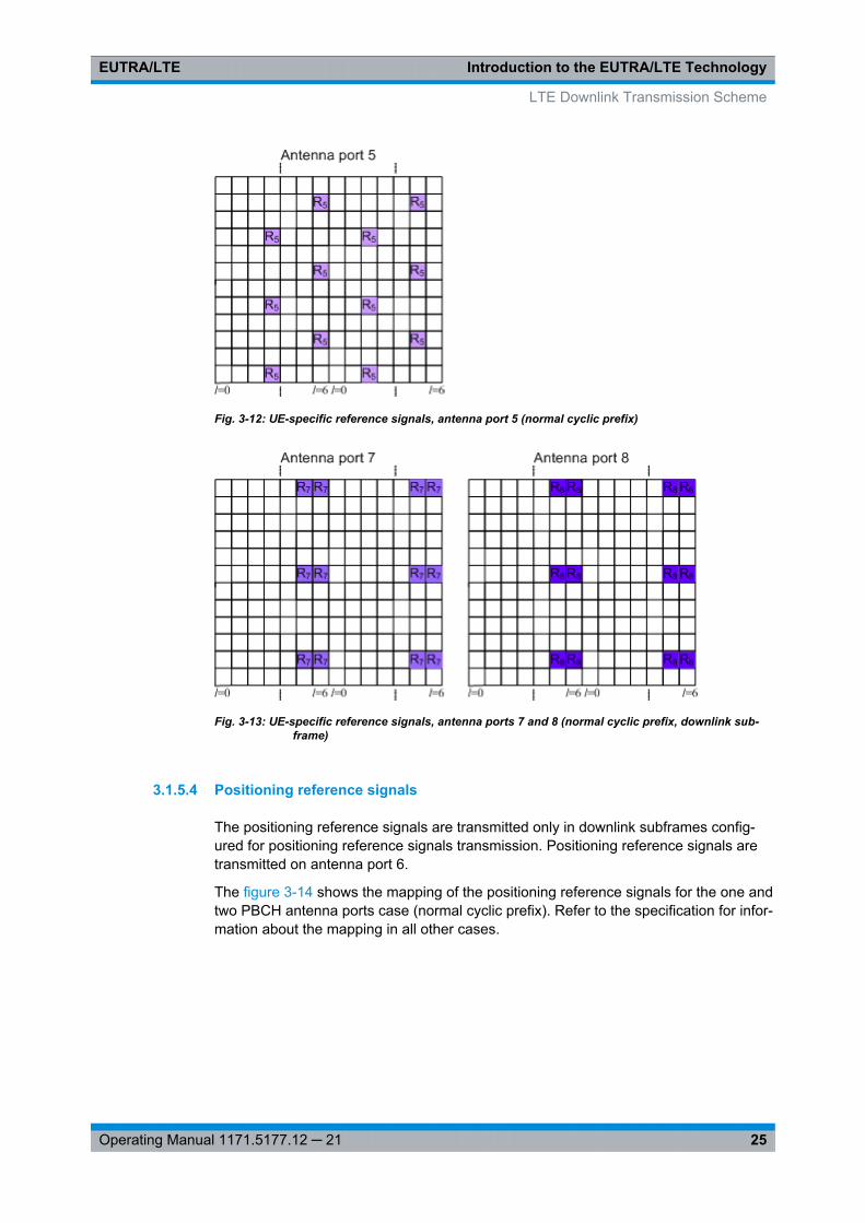
3.1.5.3 UE-specific reference signal (DM-RS)
These reference signals are intended for a specific user and mapped to predefinedPDSCH RBs of this particular user. The resource elements predefined for the UE-spe-cific RS do not overlap with the resource elements reserved for the cell-specific refer-ence signals.
In case of single-antenna transmission, the UE-specific reference signals are transmit-ted on antenna port 5, 7 or 8. If a spatial multiplexing is applied, the UE-specific refer-ence signals are transmitted on antenna ports 7 and 8.
The UE-specific RS are also called demodulation reference signals (DM-RS) and areintended for channel estimation and demodulation instead of the common referencesignals. One typical example of the application of UE-specific RS is the channel esti-mation and demodulation in case of beamforming transmission, also called transmis-sion using antenna port 5.
In contrary to the common RS that are not precoded, the UE-specific RS are precodedin the same way as the PDSCH they are mapped to.
See figure 3-12 and figure 3-13 for illustration of the mapping of the UE-specific refer-ence signals to the resource elements.
LTE Downlink Transmission Scheme
Introduction to the EUTRA/LTE TechnologyEUTRA/LTE
25Operating Manual 1171.5177.12 ─ 21
Fig. 3-12: UE-specific reference signals, antenna port 5 (normal cyclic prefix)
Fig. 3-13: UE-specific reference signals, antenna ports 7 and 8 (normal cyclic prefix, downlink sub-frame)
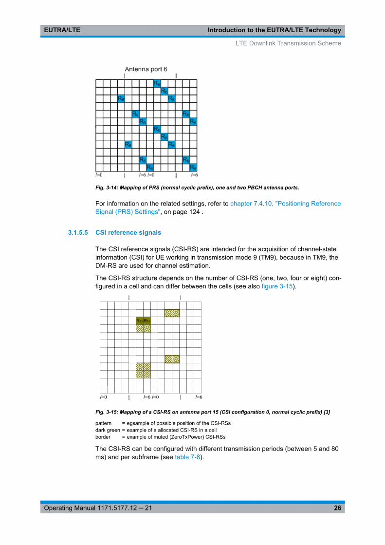
3.1.5.4 Positioning reference signals
The positioning reference signals are transmitted only in downlink subframes config-ured for positioning reference signals transmission. Positioning reference signals aretransmitted on antenna port 6.
The figure 3-14 shows the mapping of the positioning reference signals for the one andtwo PBCH antenna ports case (normal cyclic prefix). Refer to the specification for infor-mation about the mapping in all other cases.
LTE Downlink Transmission Scheme
Introduction to the EUTRA/LTE TechnologyEUTRA/LTE
26Operating Manual 1171.5177.12 ─ 21
Fig. 3-14: Mapping of PRS (normal cyclic prefix), one and two PBCH antenna ports.
For information on the related settings, refer to chapter 7.4.10, "Positioning ReferenceSignal (PRS) Settings", on page 124 .
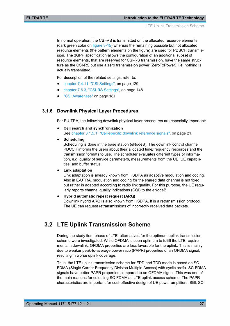
3.1.5.5 CSI reference signals
The CSI reference signals (CSI-RS) are intended for the acquisition of channel-stateinformation (CSI) for UE working in transmission mode 9 (TM9), because in TM9, theDM-RS are used for channel estimation.
The CSI-RS structure depends on the number of CSI-RS (one, two, four or eight) con-figured in a cell and can differ between the cells (see also figure 3-15).
l=0 l=6 l=0 l=6
R15R15
Fig. 3-15: Mapping of a CSI-RS on antenna port 15 (CSI configuration 0, normal cyclic prefix) [3]
pattern = egsample of possible position of the CSI-RSsdark green = example of a allocated CSI-RS in a cellborder = example of muted (ZeroTxPower) CSI-RSs
The CSI-RS can be configured with different transmission periods (between 5 and 80ms) and per subframe (see table 7-8).
LTE Downlink Transmission Scheme
Introduction to the EUTRA/LTE TechnologyEUTRA/LTE
27Operating Manual 1171.5177.12 ─ 21
In normal operation, the CSI-RS is transmitted on the allocated resource elements(dark green color on figure 3-15) whereas the remaining possible but not allocatedresource elements (the pattern elements on the figure) are used for PDSCH transmis-sion. The 3GPP specification allows the configuration of an additional subset ofresource elements, that are reserved for CSI-RS transmission, have the same struc-ture as the CSI-RS but use a zero transmission power (ZeroTxPower), i.e. nothing isactually transmitted.
For description of the related settings, refer to:● chapter 7.4.11, "CSI Settings", on page 129● chapter 7.6.3, "CSI-RS Settings", on page 148● "CSI Awareness" on page 181
3.1.6 Downlink Physical Layer Procedures
For E-UTRA, the following downlink physical layer procedures are especially important:
● Cell search and synchronizationSee chapter 3.1.5.1, "Cell-specific downlink reference signals", on page 21.
● SchedulingScheduling is done in the base station (eNodeB). The downlink control channelPDCCH informs the users about their allocated time/frequency resources and thetransmission formats to use. The scheduler evaluates different types of informa-tion, e.g. quality of service parameters, measurements from the UE, UE capabili-ties, and buffer status.
● Link adaptationLink adaptation is already known from HSDPA as adaptive modulation and coding.Also in E-UTRA, modulation and coding for the shared data channel is not fixed,but rather is adapted according to radio link quality. For this purpose, the UE regu-larly reports channel quality indications (CQI) to the eNodeB.
● Hybrid automatic repeat request (ARQ)Downlink hybrid ARQ is also known from HSDPA. It is a retransmission protocol.The UE can request retransmissions of incorrectly received data packets.
3.2 LTE Uplink Transmission Scheme
During the study item phase of LTE, alternatives for the optimum uplink transmissionscheme were investigated. While OFDMA is seen optimum to fulfill the LTE require-ments in downlink, OFDMA properties are less favorable for the uplink. This is mainlydue to weaker peak-to-average power ratio (PAPR) properties of an OFDMA signal,resulting in worse uplink coverage.
Thus, the LTE uplink transmission scheme for FDD and TDD mode is based on SC-FDMA (Single Carrier Frequency Division Multiple Access) with cyclic prefix. SC-FDMAsignals have better PAPR properties compared to an OFDMA signal. This was one ofthe main reasons for selecting SC-FDMA as LTE uplink access scheme. The PAPRcharacteristics are important for cost-effective design of UE power amplifiers. Still, SC-
LTE Uplink Transmission Scheme
Introduction to the EUTRA/LTE TechnologyEUTRA/LTE
28Operating Manual 1171.5177.12 ─ 21
FDMA signal processing has some similarities with OFDMA signal processing, soparameterization of downlink and uplink can be harmonized.
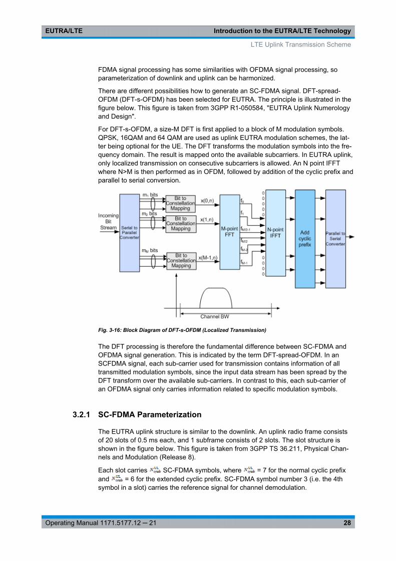
There are different possibilities how to generate an SC-FDMA signal. DFT-spread-OFDM (DFT-s-OFDM) has been selected for EUTRA. The principle is illustrated in thefigure below. This figure is taken from 3GPP R1-050584, "EUTRA Uplink Numerologyand Design".
For DFT-s-OFDM, a size-M DFT is first applied to a block of M modulation symbols.QPSK, 16QAM and 64 QAM are used as uplink EUTRA modulation schemes, the lat-ter being optional for the UE. The DFT transforms the modulation symbols into the fre-quency domain. The result is mapped onto the available subcarriers. In EUTRA uplink,only localized transmission on consecutive subcarriers is allowed. An N point IFFTwhere N>M is then performed as in OFDM, followed by addition of the cyclic prefix andparallel to serial conversion.
Fig. 3-16: Block Diagram of DFT-s-OFDM (Localized Transmission)
The DFT processing is therefore the fundamental difference between SC-FDMA andOFDMA signal generation. This is indicated by the term DFT-spread-OFDM. In anSCFDMA signal, each sub-carrier used for transmission contains information of alltransmitted modulation symbols, since the input data stream has been spread by theDFT transform over the available sub-carriers. In contrast to this, each sub-carrier ofan OFDMA signal only carries information related to specific modulation symbols.
3.2.1 SC-FDMA Parameterization
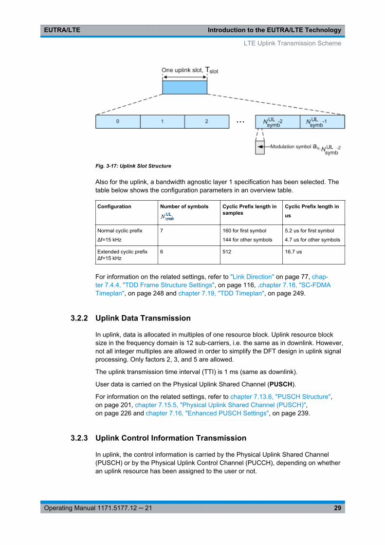
The EUTRA uplink structure is similar to the downlink. An uplink radio frame consistsof 20 slots of 0.5 ms each, and 1 subframe consists of 2 slots. The slot structure isshown in the figure below. This figure is taken from 3GPP TS 36.211, Physical Chan-nels and Modulation (Release 8).
Each slot carries SC-FDMA symbols, where = 7 for the normal cyclic prefixand = 6 for the extended cyclic prefix. SC-FDMA symbol number 3 (i.e. the 4thsymbol in a slot) carries the reference signal for channel demodulation.
LTE Uplink Transmission Scheme
Introduction to the EUTRA/LTE TechnologyEUTRA/LTE
29Operating Manual 1171.5177.12 ─ 21
Fig. 3-17: Uplink Slot Structure
Also for the uplink, a bandwidth agnostic layer 1 specification has been selected. Thetable below shows the configuration parameters in an overview table.
Configuration Number of symbols Cyclic Prefix length insamples
Cyclic Prefix length in
us
Normal cyclic prefix
Δf=15 kHz
7 160 for first symbol
144 for other symbols
5.2 us for first symbol
4.7 us for other symbols
Extended cyclic prefixΔf=15 kHz
6 512 16.7 us
For information on the related settings, refer to "Link Direction" on page 77, chap-ter 7.4.4, "TDD Frame Structure Settings", on page 116, .chapter 7.18, "SC-FDMATimeplan", on page 248 and chapter 7.19, "TDD Timeplan", on page 249.
3.2.2 Uplink Data Transmission
In uplink, data is allocated in multiples of one resource block. Uplink resource blocksize in the frequency domain is 12 sub-carriers, i.e. the same as in downlink. However,not all integer multiples are allowed in order to simplify the DFT design in uplink signalprocessing. Only factors 2, 3, and 5 are allowed.
The uplink transmission time interval (TTI) is 1 ms (same as downlink).
User data is carried on the Physical Uplink Shared Channel (PUSCH).
For information on the related settings, refer to chapter 7.13.6, "PUSCH Structure",on page 201, chapter 7.15.5, "Physical Uplink Shared Channel (PUSCH)",on page 226 and chapter 7.16, "Enhanced PUSCH Settings", on page 239.
3.2.3 Uplink Control Information Transmission
In uplink, the control information is carried by the Physical Uplink Shared Channel(PUSCH) or by the Physical Uplink Control Channel (PUCCH), depending on whetheran uplink resource has been assigned to the user or not.
LTE Uplink Transmission Scheme
Introduction to the EUTRA/LTE TechnologyEUTRA/LTE
30Operating Manual 1171.5177.12 ─ 21
Control information (CQI reports and ACK/NACK information related to data packetsreceived in the downlink) is multiplexed with the PUSCH, if the user has been grantedwith UL-SCH transmission.
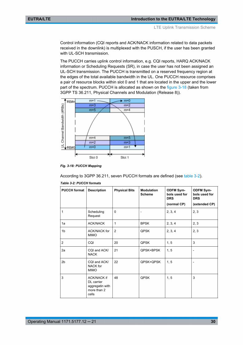
The PUCCH carries uplink control information, e.g. CQI reports, HARQ ACK/NACKinformation or Scheduling Requests (SR), in case the user has not been assigned anUL-SCH transmission. The PUCCH is transmitted on a reserved frequency region atthe edges of the total available bandwidth in the UL. One PUCCH resource comprisesa pair of resource blocks within slot 0 and 1 that are located in the upper and the lowerpart of the spectrum. PUCCH is allocated as shown on the figure 3-18 (taken from3GPP TS 36.211, Physical Channels and Modulation (Release 8)).
Fig. 3-18: PUCCH Mapping
According to 3GPP 36.211, seven PUCCH formats are defined (see table 3-2).
Table 3-2: PUCCH formats
PUCCH format Description Physical Bits ModulationScheme
ODFM Sym-bols used forDRS
(normal CP)
ODFM Sym-bols used forDRS
(extended CP)
1 SchedulingRequest
0 - 2, 3, 4 2, 3
1a ACK/NACK 1 BPSK 2, 3, 4 2, 3
1b ACK/NACK forMIMO
2 QPSK 2, 3, 4 2, 3
2 CQI 20 QPSK 1, 5 3
2a CQI and ACK/NACK
21 QPSK+BPSK 1, 5 -
2b CQI and ACK/NACK forMIMO
22 QPSK+QPSK 1, 5 -
3 ACK/NACK ifDL carrieraggregatin withmore than 2cells
48 QPSK 1, 5 3
LTE Uplink Transmission Scheme
Introduction to the EUTRA/LTE TechnologyEUTRA/LTE
31Operating Manual 1171.5177.12 ─ 21
The different PUCCH formats are mapped to the reserved PUCCH region, so thatthere can be only one resource block per slot that supports a combination of PUCCHformats 1/1a/1b and 2/2a/2b.
For simultaneous transmission of multiple users on the PUCCH, different PUCCHresource indices are used. Multiple users are distinguished within one resource blockby using different cyclic shifts (CS) of the CAZAC (Constant Amplitude Zero Auto-Cor-relation) sequence. For PUCCH formats 1/1a/1b additionally three different orthogonalcover sequences (OC) can be used. For the different PUCCH formats, different num-ber of PUCCH resource indices are available within a resource block (see table below).The actual number of the used orthogonal sequences is additionally determinate by theparameter delta_shift, used to support working by different channel conditions.
PUCCH format PUCCH resource indices number available within aresource block
1/1a/1b N(1)_PUCCH 36 for normal CP
24 for extended CP
2/2a/2b N(2)_PUCCH 12
3 N(3)_PUCCH 5
For information on the related settings, refer to chapter 7.13.7, "PUCCH Structure",on page 202 and chapter 7.17, "Enhanced PUCCH Settings", on page 244.
3.2.4 Uplink Reference Signal Structure
Uplink reference signals are used for two different purposes: on the one hand, they areused for channel estimation in the eNodeB receiver in order to demodulate control anddata channels. On the other hand, the reference signals provide channel quality infor-mation as a basis for scheduling decisions in the base station. The latter purpose isalso called channel sounding.
The uplink reference signals are based on CAZAC (Constant Amplitude Zero Auto-Correlation) sequences. The specification defines two types of sounding reference sig-nals (SRS), periodic SRS and aperiodic SRS.
For information on the related settings, refer to:● chapter 7.13.4, "UL Reference Signals", on page 198● chapter 7.13.8, "SRS Structure", on page 204● chapter 7.15.6, "Reference Signal Structure", on page 229● chapter 7.15.7, "SRS Structure", on page 231● "Aperiodic SRS" on page 181
3.2.5 Uplink Physical Layer Procedures
For EUTRA, the following uplink physical layer procedures are especially important:
LTE Uplink Transmission Scheme
Introduction to the EUTRA/LTE TechnologyEUTRA/LTE
32Operating Manual 1171.5177.12 ─ 21
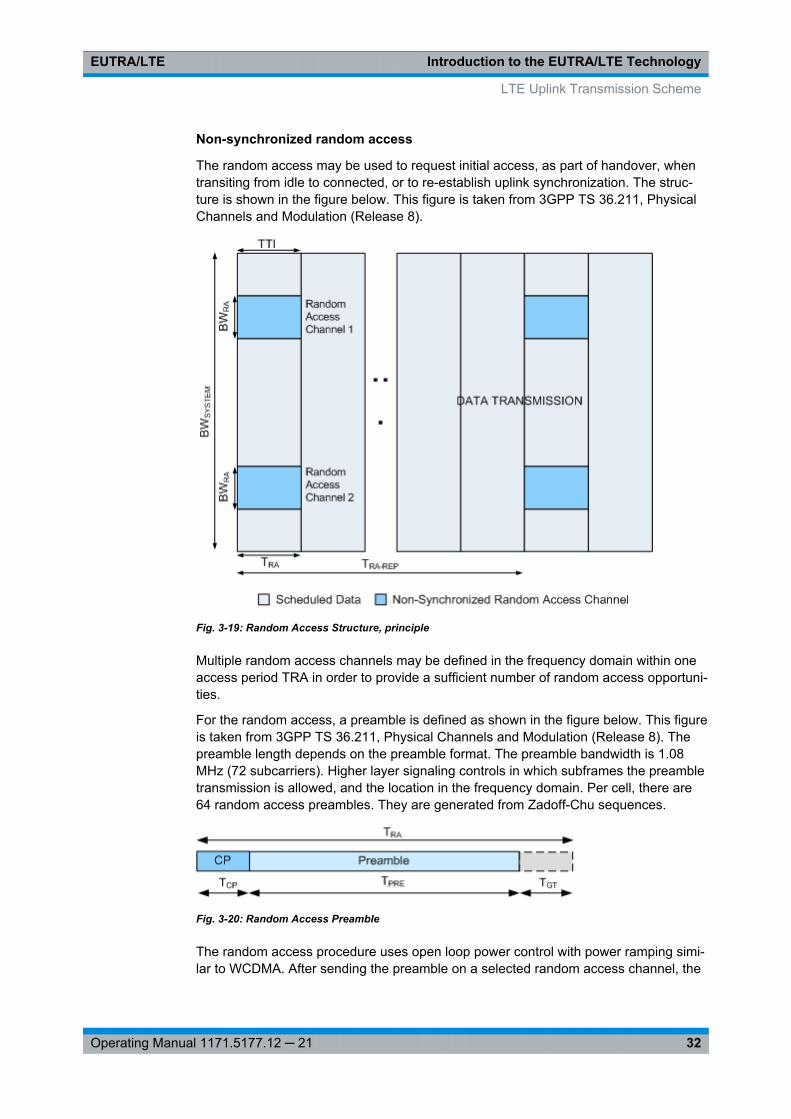
Non-synchronized random access
The random access may be used to request initial access, as part of handover, whentransiting from idle to connected, or to re-establish uplink synchronization. The struc-ture is shown in the figure below. This figure is taken from 3GPP TS 36.211, PhysicalChannels and Modulation (Release 8).
Fig. 3-19: Random Access Structure, principle
Multiple random access channels may be defined in the frequency domain within oneaccess period TRA in order to provide a sufficient number of random access opportuni-ties.
For the random access, a preamble is defined as shown in the figure below. This figureis taken from 3GPP TS 36.211, Physical Channels and Modulation (Release 8). Thepreamble length depends on the preamble format. The preamble bandwidth is 1.08MHz (72 subcarriers). Higher layer signaling controls in which subframes the preambletransmission is allowed, and the location in the frequency domain. Per cell, there are64 random access preambles. They are generated from Zadoff-Chu sequences.
Fig. 3-20: Random Access Preamble
The random access procedure uses open loop power control with power ramping simi-lar to WCDMA. After sending the preamble on a selected random access channel, the
LTE Uplink Transmission Scheme
Introduction to the EUTRA/LTE TechnologyEUTRA/LTE
33Operating Manual 1171.5177.12 ─ 21
UE waits for the random access response message. If no response is detected thenanother random access channel is selected and a preamble is sent again.
For information on the related settings, refer to chapter 7.13.5, "PRACH Settings",on page 199, chapter 7.15.8, "PRACH Power Ramping", on page 237 and chap-ter 7.15.9, "PRACH Configuration", on page 237.
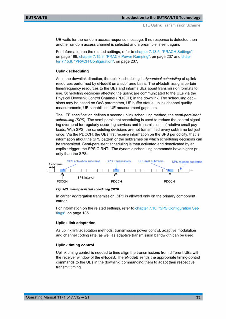
Uplink scheduling
As in the downlink direction, the uplink scheduling is dynamical scheduling of uplinkresources performed by eNodeB on a subframe basis. The eNodeB assigns certaintime/frequency resources to the UEs and informs UEs about transmission formats touse. Scheduling decisions affecting the uplink are communicated to the UEs via thePhysical Downlink Control Channel (PDCCH) in the downlink. The scheduling deci-sions may be based on QoS parameters, UE buffer status, uplink channel qualitymeasurements, UE capabilities, UE measurement gaps, etc.
The LTE specification defines a second uplink scheduling method, the semi-persistentscheduling (SPS). The semi-persistent scheduling is used to reduce the control signal-ing overhead for regularly occurring services and transmissions of relative small pay-loads. With SPS, the scheduling decisions are not transmitted every subframe but justonce. Via the PDCCH, the UEs first receive information on the SPS periodicity, that isinformation about the SPS pattern or the subframes on which scheduling decisions canbe transmitted. Semi-persistent scheduling is then activated and deactivated by anexplicit trigger, the SPS C-RNTI. The dynamic scheduling commands have higher pri-ority than the SPS.
Fig. 3-21: Semi-persistent scheduling (SPS)
In carrier aggregation transmission, SPS is allowed only on the primary componentcarrier.
For information on the related settings, refer to chapter 7.10, "SPS Configuration Set-tings", on page 185.
Uplink link adaptation
As uplink link adaptation methods, transmission power control, adaptive modulationand channel coding rate, as well as adaptive transmission bandwidth can be used.
Uplink timing control
Uplink timing control is needed to time align the transmissions from different UEs withthe receiver window of the eNodeB. The eNodeB sends the appropriate timing-controlcommands to the UEs in the downlink, commanding them to adapt their respectivetransmit timing.
LTE Uplink Transmission Scheme
Introduction to the EUTRA/LTE TechnologyEUTRA/LTE
34Operating Manual 1171.5177.12 ─ 21
Hybrid automatic repeat request (ARQ)
The Uplink Hybrid ARQ protocol is already known from HSUPA. The eNodeB has thecapability to request retransmissions of incorrectly received data packets.
3.3 LTE MIMO Concepts
Multiple Input Multiple Output (MIMO) systems form an essential part of LTE in order toachieve the ambitious requirements for throughput and spectral efficiency. MIMOrefers to the use of multiple antennas at transmitter and receiver side.
3.3.1 Downlink MIMO
For the LTE downlink, a 2x2 configuration for MIMO is assumed as baseline configura-tion, i.e. 2 transmit antennas at the base station and 2 receive antennas at the terminalside. Configurations with 4 or more antennas are also being considered.
Different MIMO modes are envisaged. It has to be differentiated between spatial multi-plexing and transmit diversity, and it depends on the channel condition which schemeto select.
For information on the related settings, refer to● chapter 7.4.6, "MIMO", on page 118● chapter 7.6.2, "Precoding Settings", on page 144● chapter 7.9, "Antenna Port Mapping Settings", on page 181.
3.3.1.1 Spatial Multiplexing
Spatial multiplexing allows transmitting different streams of data simultaneously on thesame downlink resource block(s). These data streams can belong to one single user(single user MIMO / SU-MIMO) or to different users (multi user MIMO / MU-MIMO).While SU-MIMO increases the data rate of one user, MU-MIMO allows increasing theoverall capacity. Spatial multiplexing is only possible if the mobile radio channel allowsit. The figure below shows the principle of spatial multiplexing, exploiting the spatialdimension of the radio channel which allows transmitting the different data streamssimultaneously.
LTE MIMO Concepts
Introduction to the EUTRA/LTE TechnologyEUTRA/LTE
35Operating Manual 1171.5177.12 ─ 21
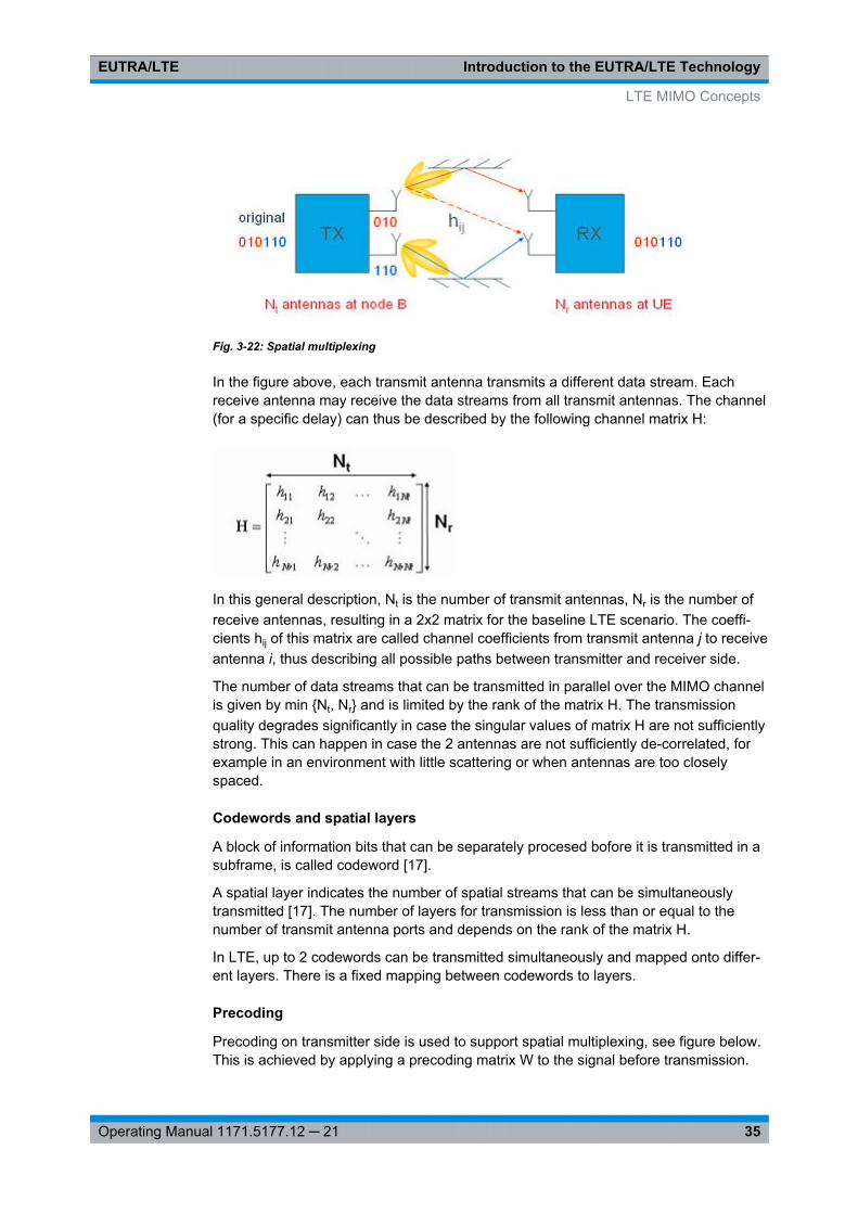
Fig. 3-22: Spatial multiplexing
In the figure above, each transmit antenna transmits a different data stream. Eachreceive antenna may receive the data streams from all transmit antennas. The channel(for a specific delay) can thus be described by the following channel matrix H:
In this general description, Nt is the number of transmit antennas, Nr is the number ofreceive antennas, resulting in a 2x2 matrix for the baseline LTE scenario. The coeffi-cients hij of this matrix are called channel coefficients from transmit antenna j to receiveantenna i, thus describing all possible paths between transmitter and receiver side.
The number of data streams that can be transmitted in parallel over the MIMO channelis given by min {Nt, Nr} and is limited by the rank of the matrix H. The transmissionquality degrades significantly in case the singular values of matrix H are not sufficientlystrong. This can happen in case the 2 antennas are not sufficiently de-correlated, forexample in an environment with little scattering or when antennas are too closelyspaced.
Codewords and spatial layers
A block of information bits that can be separately procesed bofore it is transmitted in asubframe, is called codeword [17].
A spatial layer indicates the number of spatial streams that can be simultaneouslytransmitted [17]. The number of layers for transmission is less than or equal to thenumber of transmit antenna ports and depends on the rank of the matrix H.
In LTE, up to 2 codewords can be transmitted simultaneously and mapped onto differ-ent layers. There is a fixed mapping between codewords to layers.
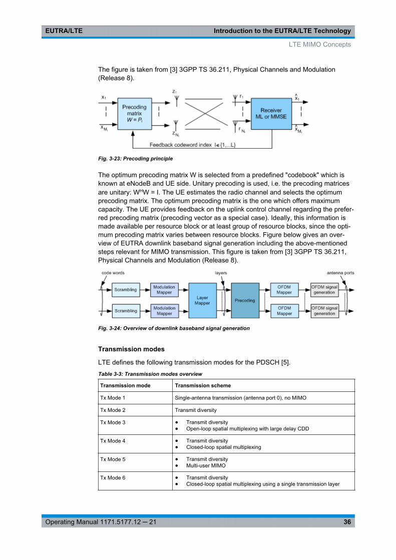
Precoding
Precoding on transmitter side is used to support spatial multiplexing, see figure below.This is achieved by applying a precoding matrix W to the signal before transmission.
LTE MIMO Concepts
Introduction to the EUTRA/LTE TechnologyEUTRA/LTE
36Operating Manual 1171.5177.12 ─ 21
The figure is taken from [3] 3GPP TS 36.211, Physical Channels and Modulation(Release 8).
Fig. 3-23: Precoding principle
The optimum precoding matrix W is selected from a predefined "codebook" which isknown at eNodeB and UE side. Unitary precoding is used, i.e. the precoding matricesare unitary: WHW = I. The UE estimates the radio channel and selects the optimumprecoding matrix. The optimum precoding matrix is the one which offers maximumcapacity. The UE provides feedback on the uplink control channel regarding the prefer-red precoding matrix (precoding vector as a special case). Ideally, this information ismade available per resource block or at least group of resource blocks, since the opti-mum precoding matrix varies between resource blocks. Figure below gives an over-view of EUTRA downlink baseband signal generation including the above-mentionedsteps relevant for MIMO transmission. This figure is taken from [3] 3GPP TS 36.211,Physical Channels and Modulation (Release 8).
Fig. 3-24: Overview of downlink baseband signal generation
Transmission modes
LTE defines the following transmission modes for the PDSCH [5].
Table 3-3: Transmission modes overview
Transmission mode Transmission scheme
Tx Mode 1 Single-antenna transmission (antenna port 0), no MIMO
Tx Mode 2 Transmit diversity
Tx Mode 3 ● Transmit diversity● Open-loop spatial multiplexing with large delay CDD
Tx Mode 4 ● Transmit diversity● Closed-loop spatial multiplexing
Tx Mode 5 ● Transmit diversity● Multi-user MIMO
Tx Mode 6 ● Transmit diversity● Closed-loop spatial multiplexing using a single transmission layer
LTE MIMO Concepts
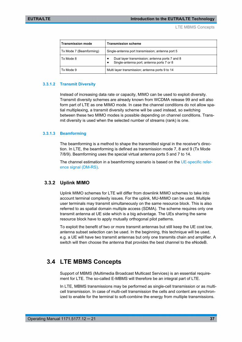
Introduction to the EUTRA/LTE TechnologyEUTRA/LTE
37Operating Manual 1171.5177.12 ─ 21
Transmission mode Transmission scheme
Tx Mode 7 (Beamforming) Single-antenna port transmission; antenna port 5
Tx Mode 8 ● Dual layer transmission; antenna ports 7 and 8● Single-antenna port; antenna ports 7 or 8
Tx Mode 9 Multi layer transmission; antenna ports 9 to 14
3.3.1.2 Transmit Diversity
Instead of increasing data rate or capacity, MIMO can be used to exploit diversity.Transmit diversity schemes are already known from WCDMA release 99 and will alsoform part of LTE as one MIMO mode. In case the channel conditions do not allow spa-tial multiplexing, a transmit diversity scheme will be used instead, so switchingbetween these two MIMO modes is possible depending on channel conditions. Trans-mit diversity is used when the selected number of streams (rank) is one.
3.3.1.3 Beamforming
The beamforming is a method to shape the transmitted signal in the receiver's direc-tion. In LTE, the beamforming is defined as transmission mode 7, 8 and 9 (Tx Mode7/8/9). Beamforming uses the special virtual antenna ports 5 and 7 to 14.
The channel estimation in a beamforming scenario is based on the UE-specific refer-ence signal (DM-RS).
3.3.2 Uplink MIMO
Uplink MIMO schemes for LTE will differ from downlink MIMO schemes to take intoaccount terminal complexity issues. For the uplink, MU-MIMO can be used. Multipleuser terminals may transmit simultaneously on the same resource block. This is alsoreferred to as spatial domain multiple access (SDMA). The scheme requires only onetransmit antenna at UE side which is a big advantage. The UEs sharing the sameresource block have to apply mutually orthogonal pilot patterns.
To exploit the benefit of two or more transmit antennas but still keep the UE cost low,antenna subset selection can be used. In the beginning, this technique will be used,e.g. a UE will have two transmit antennas but only one transmits chain and amplifier. Aswitch will then choose the antenna that provides the best channel to the eNodeB.
3.4 LTE MBMS Concepts
Support of MBMS (Multimedia Broadcast Multicast Services) is an essential require-ment for LTE. The so-called E-MBMS will therefore be an integral part of LTE.
In LTE, MBMS transmissions may be performed as single-cell transmission or as multi-cell transmission. In case of multi-cell transmission the cells and content are synchron-ized to enable for the terminal to soft-combine the energy from multiple transmissions.
LTE MBMS Concepts
Introduction to the EUTRA/LTE TechnologyEUTRA/LTE
38Operating Manual 1171.5177.12 ─ 21
The superimposed signal looks like multipath to the terminal. This concept is alsoknown as Single Frequency Network (SFN). The EUTRAN can configure which cellsare part of an SFN for transmission of an MBMS service. The MBMS traffic can sharethe same carrier with the unicast traffic or be sent on a separate carrier. For MBMStraffic, an extended cyclic prefix is provided. In case of subframes carrying MBMS SFNdata, specific reference signals are used (see chapter 3.1.5.2, "MBSFN reference sig-nals", on page 23).
MBMS data is carried on the MBMS traffic channel (MTCH) as logical channel. TheMBMS control information is conveyed by the MBMS control channel MCCH. Both logi-cal channels, the MTCH and the MCCH, are mapped onto the physical multicast chan-nel PMCH in the multi-cell transmission case and on the PDSCH in case a single-celltransmission is used.
For information on the related settings, refer to chapter 7.4.2, "MBSFN Settings",on page 102.
3.5 LTE-Advanced Introduction
In September 2009 the 3GPP Partners made a formal submission to the ITU proposingthat LTE Release 10 & beyond (LTE-Advanced) should be evaluated as a candidatefor IMT-Advanced.
This description gives a brief description only of the LTE-A features currently coveredby the software option R&S SMx/AMU-K85. The full set of LTE-Advanced features isdescribed in [20].For a complete LTE-Advanced technology introduction and an insight description of theLTE-A features, refer to the following Rohde & Schwarz documents:● Withe Paper 1MA169 "LTE-Advanced Technology Introduction" [18]● Application Note 1MA166 "LTE-Advanced Signals Generation and –Analysis"” [19]
The last two documents can be found in the official Rohde & Schwarz internet site >Download Area > Application Notes: http://www2.rohde-schwarz.com/en/service_and_support/Downloads/Application_Notes/
3.5.1 Carrier Aggregation
To fulfill the requirements to even higher data rates as in the LTE Rel. 8, the LTE-ARel. 10 specification uses the aggregation of multiple LTE carrier. Two or more compo-nent carrier (CC) are grouped in order to support wider transmission bandwidths up to100MHz. To an LTE REl. 8 terminal, each component carrier will appear as an LTEcarrier, while an LTE Rel 10 terminal can exploit the total aggregated bandwidth. Asbackward compatibility is fulfilled, a LTE-advanced cell can serve both LTE Rel 8 andLTE Rel 10 terminals simultaneously.
Spectrum deployment may be either contiguous with adjacent component carriers, ornon-contiguous with non-adjacent component carriers (see figure 3-25). The individual
LTE-Advanced Introduction
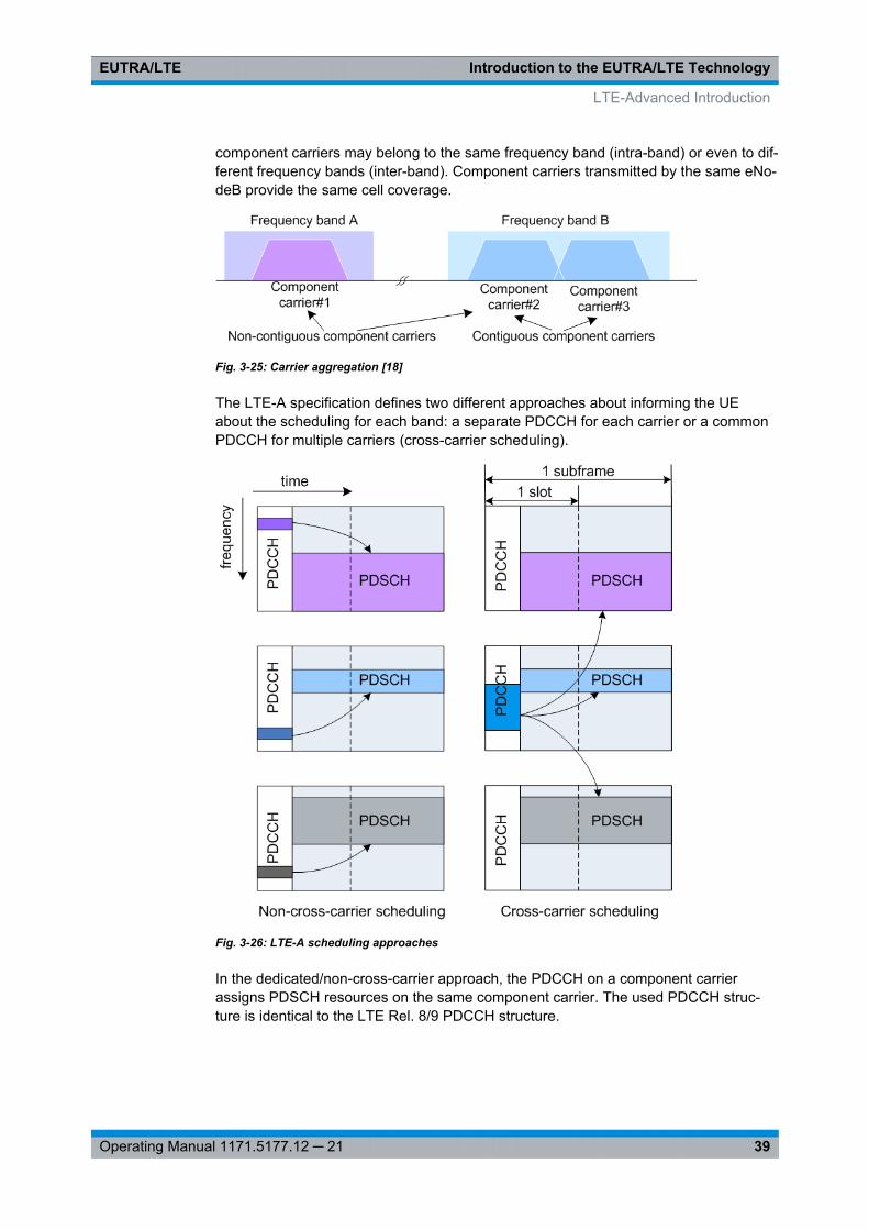
Introduction to the EUTRA/LTE TechnologyEUTRA/LTE
39Operating Manual 1171.5177.12 ─ 21
component carriers may belong to the same frequency band (intra-band) or even to dif-ferent frequency bands (inter-band). Component carriers transmitted by the same eNo-deB provide the same cell coverage.
Fig. 3-25: Carrier aggregation [18]
The LTE-A specification defines two different approaches about informing the UEabout the scheduling for each band: a separate PDCCH for each carrier or a commonPDCCH for multiple carriers (cross-carrier scheduling).
Fig. 3-26: LTE-A scheduling approaches
In the dedicated/non-cross-carrier approach, the PDCCH on a component carrierassigns PDSCH resources on the same component carrier. The used PDCCH struc-ture is identical to the LTE Rel. 8/9 PDCCH structure.
LTE-Advanced Introduction
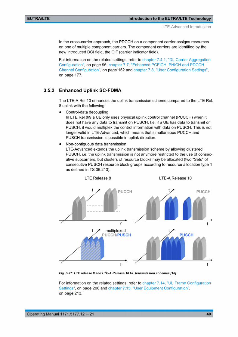
Introduction to the EUTRA/LTE TechnologyEUTRA/LTE
40Operating Manual 1171.5177.12 ─ 21
In the cross-carrier approach, the PDCCH on a component carrier assigns resourceson one of multiple component carriers. The component carriers are identified by thenew introduced DCI field, the CIF (carrier indicator field).
For information on the related settings, refer to chapter 7.4.1, "DL Carrier AggregationConfiguration", on page 96, chapter 7.7, "Enhanced PCFICH, PHICH and PDCCHChannel Configuration", on page 152 and chapter 7.8, "User Configuration Settings",on page 177.
3.5.2 Enhanced Uplink SC-FDMA
The LTE-A Rel 10 enhances the uplink transmission scheme compared to the LTE Rel.8 uplink with the following:● Control-data decoupling
In LTE Rel 8/9 a UE only uses physical uplink control channel (PUCCH) when itdoes not have any data to transmit on PUSCH. I.e. if a UE has data to transmit onPUSCH, it would multiplex the control information with data on PUSCH. This is notlonger valid in LTE-Advanced, which means that simultaneous PUCCH andPUSCH transmission is possible in uplink direction.
● Non-contiguous data transmissionLTE-Advanced extends the uplink transmission scheme by allowing clusteredPUSCH, i.e. the uplink transmission is not anymore restricted to the use of consec-utive subcarriers, but clusters of resource blocks may be allocated (two "Sets" ofconsecutive PUSCH resource block groups according to resource allocation type 1as defined in TS 36.213).
Fig. 3-27: LTE release 8 and LTE-A Release 10 UL transmission schemes [18]
For information on the related settings, refer to chapter 7.14, "UL Frame ConfigurationSettings", on page 206 and chapter 7.15, "User Equipment Configuration",on page 213.
LTE-Advanced Introduction
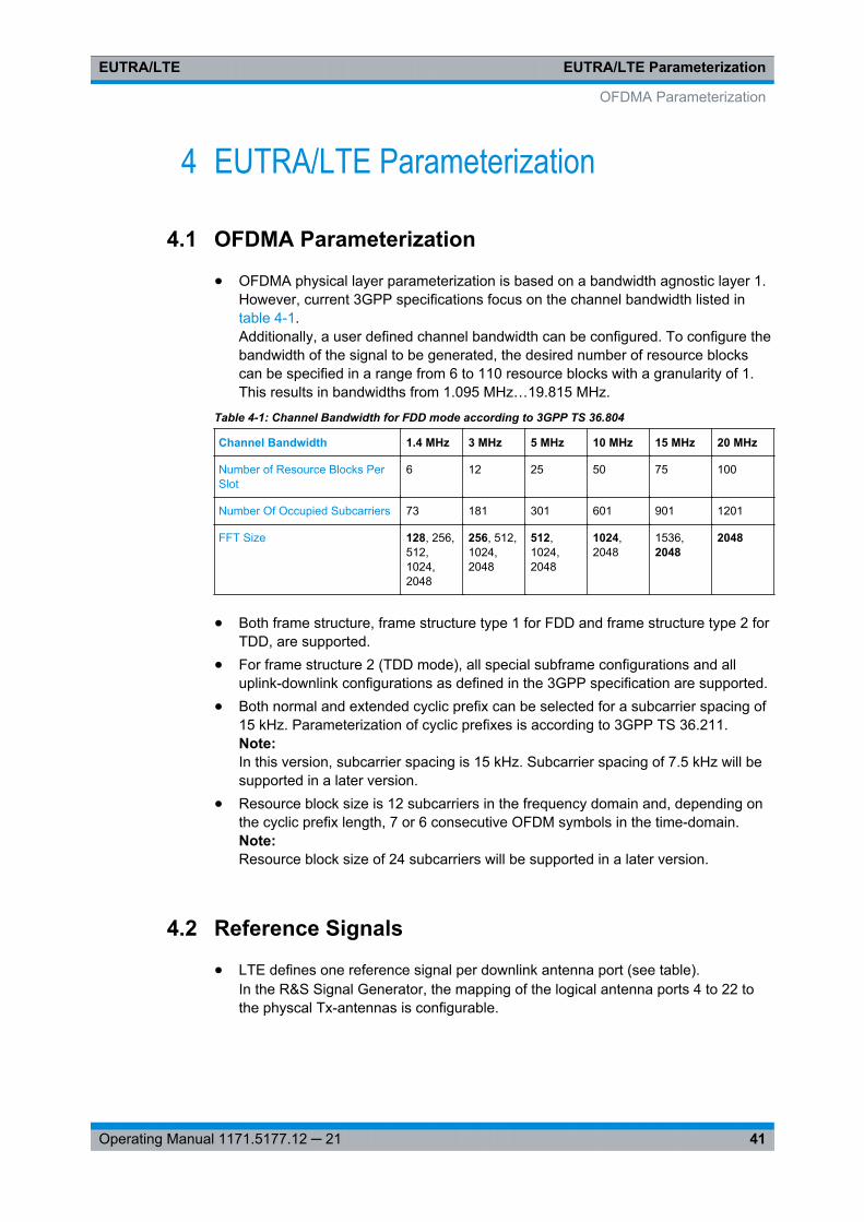
EUTRA/LTE ParameterizationEUTRA/LTE
41Operating Manual 1171.5177.12 ─ 21
4 EUTRA/LTE Parameterization
4.1 OFDMA Parameterization
● OFDMA physical layer parameterization is based on a bandwidth agnostic layer 1.However, current 3GPP specifications focus on the channel bandwidth listed intable 4-1.Additionally, a user defined channel bandwidth can be configured. To configure thebandwidth of the signal to be generated, the desired number of resource blockscan be specified in a range from 6 to 110 resource blocks with a granularity of 1.This results in bandwidths from 1.095 MHz…19.815 MHz.
Table 4-1: Channel Bandwidth for FDD mode according to 3GPP TS 36.804
Channel Bandwidth 1.4 MHz 3 MHz 5 MHz 10 MHz 15 MHz 20 MHz
Number of Resource Blocks PerSlot
6 12 25 50 75 100
Number Of Occupied Subcarriers 73 181 301 601 901 1201
FFT Size 128, 256,512,1024,2048
256, 512,1024,2048
512,1024,2048
1024,2048
1536,2048
2048
● Both frame structure, frame structure type 1 for FDD and frame structure type 2 forTDD, are supported.
● For frame structure 2 (TDD mode), all special subframe configurations and alluplink-downlink configurations as defined in the 3GPP specification are supported.
● Both normal and extended cyclic prefix can be selected for a subcarrier spacing of15 kHz. Parameterization of cyclic prefixes is according to 3GPP TS 36.211.Note:In this version, subcarrier spacing is 15 kHz. Subcarrier spacing of 7.5 kHz will besupported in a later version.
● Resource block size is 12 subcarriers in the frequency domain and, depending onthe cyclic prefix length, 7 or 6 consecutive OFDM symbols in the time-domain.Note:Resource block size of 24 subcarriers will be supported in a later version.
4.2 Reference Signals
● LTE defines one reference signal per downlink antenna port (see table).In the R&S Signal Generator, the mapping of the logical antenna ports 4 to 22 tothe physcal Tx-antennas is configurable.
OFDMA Parameterization
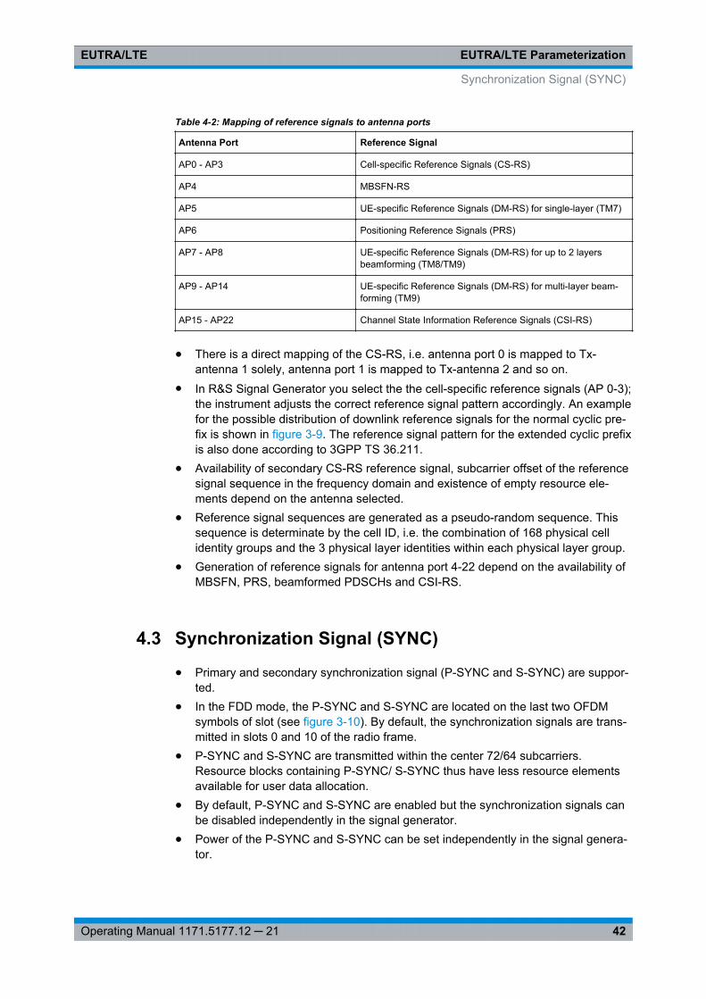
EUTRA/LTE ParameterizationEUTRA/LTE
42Operating Manual 1171.5177.12 ─ 21
Table 4-2: Mapping of reference signals to antenna ports
Antenna Port Reference Signal
AP0 - AP3 Cell-specific Reference Signals (CS-RS)
AP4 MBSFN-RS
AP5 UE-specific Reference Signals (DM-RS) for single-layer (TM7)
AP6 Positioning Reference Signals (PRS)
AP7 - AP8 UE-specific Reference Signals (DM-RS) for up to 2 layersbeamforming (TM8/TM9)
AP9 - AP14 UE-specific Reference Signals (DM-RS) for multi-layer beam-forming (TM9)
AP15 - AP22 Channel State Information Reference Signals (CSI-RS)
● There is a direct mapping of the CS-RS, i.e. antenna port 0 is mapped to Tx-antenna 1 solely, antenna port 1 is mapped to Tx-antenna 2 and so on.
● In R&S Signal Generator you select the the cell-specific reference signals (AP 0-3);the instrument adjusts the correct reference signal pattern accordingly. An examplefor the possible distribution of downlink reference signals for the normal cyclic pre-fix is shown in figure 3-9. The reference signal pattern for the extended cyclic prefixis also done according to 3GPP TS 36.211.
● Availability of secondary CS-RS reference signal, subcarrier offset of the referencesignal sequence in the frequency domain and existence of empty resource ele-ments depend on the antenna selected.
● Reference signal sequences are generated as a pseudo-random sequence. Thissequence is determinate by the cell ID, i.e. the combination of 168 physical cellidentity groups and the 3 physical layer identities within each physical layer group.
● Generation of reference signals for antenna port 4-22 depend on the availability ofMBSFN, PRS, beamformed PDSCHs and CSI-RS.
4.3 Synchronization Signal (SYNC)
● Primary and secondary synchronization signal (P-SYNC and S-SYNC) are suppor-ted.
● In the FDD mode, the P-SYNC and S-SYNC are located on the last two OFDMsymbols of slot (see figure 3-10). By default, the synchronization signals are trans-mitted in slots 0 and 10 of the radio frame.
● P-SYNC and S-SYNC are transmitted within the center 72/64 subcarriers.Resource blocks containing P-SYNC/ S-SYNC thus have less resource elementsavailable for user data allocation.
● By default, P-SYNC and S-SYNC are enabled but the synchronization signals canbe disabled independently in the signal generator.
● Power of the P-SYNC and S-SYNC can be set independently in the signal genera-tor.
Synchronization Signal (SYNC)
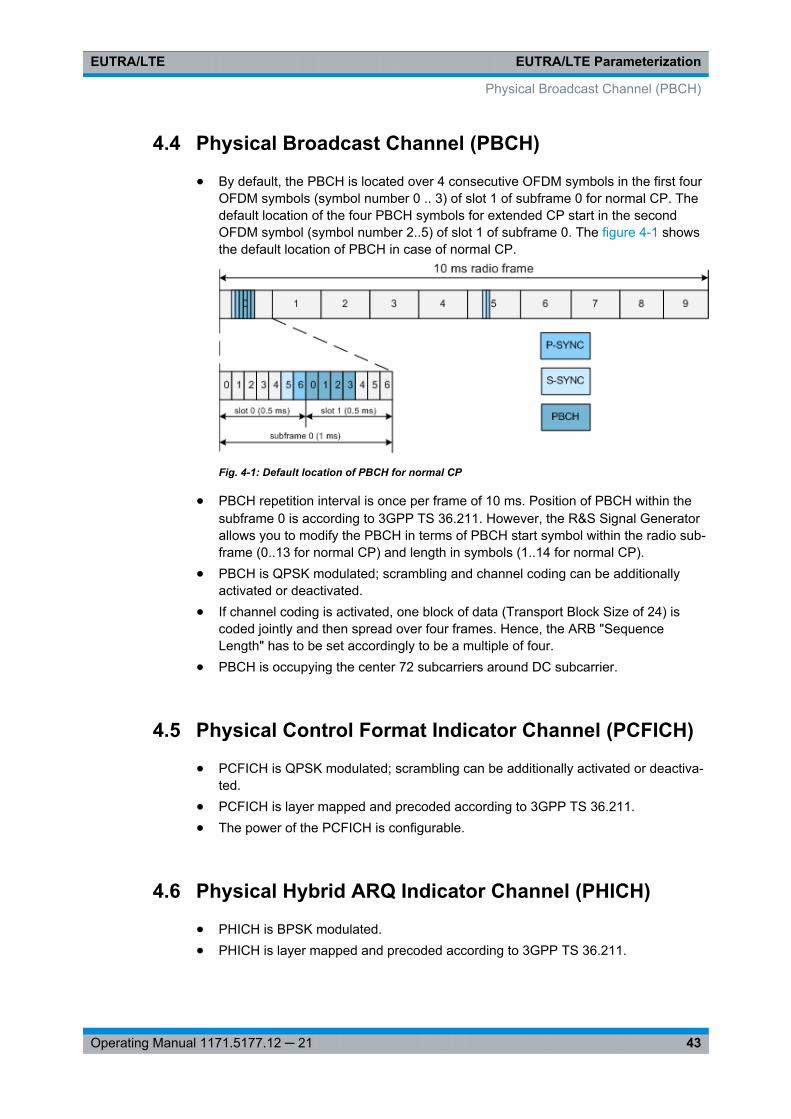
EUTRA/LTE ParameterizationEUTRA/LTE
43Operating Manual 1171.5177.12 ─ 21
4.4 Physical Broadcast Channel (PBCH)
● By default, the PBCH is located over 4 consecutive OFDM symbols in the first fourOFDM symbols (symbol number 0 .. 3) of slot 1 of subframe 0 for normal CP. Thedefault location of the four PBCH symbols for extended CP start in the secondOFDM symbol (symbol number 2..5) of slot 1 of subframe 0. The figure 4-1 showsthe default location of PBCH in case of normal CP.
Fig. 4-1: Default location of PBCH for normal CP
● PBCH repetition interval is once per frame of 10 ms. Position of PBCH within thesubframe 0 is according to 3GPP TS 36.211. However, the R&S Signal Generatorallows you to modify the PBCH in terms of PBCH start symbol within the radio sub-frame (0..13 for normal CP) and length in symbols (1..14 for normal CP).
● PBCH is QPSK modulated; scrambling and channel coding can be additionallyactivated or deactivated.
● If channel coding is activated, one block of data (Transport Block Size of 24) iscoded jointly and then spread over four frames. Hence, the ARB "SequenceLength" has to be set accordingly to be a multiple of four.
● PBCH is occupying the center 72 subcarriers around DC subcarrier.
4.5 Physical Control Format Indicator Channel (PCFICH)
● PCFICH is QPSK modulated; scrambling can be additionally activated or deactiva-ted.
● PCFICH is layer mapped and precoded according to 3GPP TS 36.211.● The power of the PCFICH is configurable.
4.6 Physical Hybrid ARQ Indicator Channel (PHICH)
● PHICH is BPSK modulated.● PHICH is layer mapped and precoded according to 3GPP TS 36.211.
Physical Broadcast Channel (PBCH)
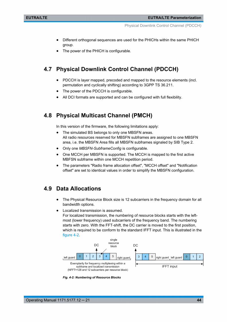
EUTRA/LTE ParameterizationEUTRA/LTE
44Operating Manual 1171.5177.12 ─ 21
● Different orthogonal sequences are used for the PHICHs within the same PHICHgroup.
● The power of the PHICH is configurable.
4.7 Physical Downlink Control Channel (PDCCH)
● PDCCH is layer mapped, precoded and mapped to the resource elements (incl.permutation and cyclically shifting) according to 3GPP TS 36.211.
● The power of the PDCCH is configurable.● All DCI formats are supported and can be configured with full flexibility.
4.8 Physical Multicast Channel (PMCH)
In this version of the firmware, the following limitations apply:● The simulated BS belongs to only one MBSFN areas.
All radio resources reserved for MBSFN subframes are assigned to one MBSFNarea, i.e. the MBSFN Area fills all MBSFN subframes signaled by SIB Type 2.
● Only one MBSFN-SubframeConfig is configurable.● One MCCH per MBSFN is supported. The MCCH is mapped to the first active
MBFSN subframe within one MCCH repetition period.● The parameters "Radio frame allocation offset", "MCCH offset" and "Notification
offset" are set to identical values in order to simplify the MBSFN configuration.
4.9 Data Allocations
● The Physical Resource Block size is 12 subcarriers in the frequency domain for allbandwidth options.
● Localized transmission is assumed.For localized transmission, the numbering of resource blocks starts with the left-most (lower frequency) used subcarriers of the frequency band. The numberingstarts with zero. With the FFT-shift, the DC carrier is moved to the first position,which is required to be conform to the standard IFFT input. This is illustrated in thefigure 4-2.
Fig. 4-2: Numbering of Resource Blocks
Physical Downlink Control Channel (PDCCH)
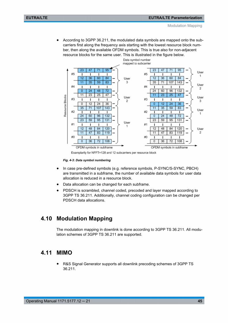
EUTRA/LTE ParameterizationEUTRA/LTE
45Operating Manual 1171.5177.12 ─ 21
● According to 3GPP 36.211, the modulated data symbols are mapped onto the sub-carriers first along the frequency axis starting with the lowest resource block num-ber, then along the available OFDM symbols. This is true also for non-adjacentresource blocks for the same user. This is illustrated in the figure below.
Fig. 4-3: Data symbol numbering
● In case pre-defined symbols (e.g. reference symbols, P-SYNC/S-SYNC, PBCH)are transmitted in a subframe, the number of available data symbols for user dataallocation is reduced in a resource block.
● Data allocation can be changed for each subframe.● PDSCH is scrambled, channel coded, precoded and layer mapped according to
3GPP TS 36.211. Additionally, channel coding configuration can be changed perPDSCH data allocations.
4.10 Modulation Mapping
The modulation mapping in downlink is done according to 3GPP TS 36.211. All modu-lation schemes of 3GPP TS 36.211 are supported.
4.11 MIMO
● R&S Signal Generator supports all downlink precoding schemes of 3GPP TS36.211.
Modulation Mapping
EUTRA/LTE ParameterizationEUTRA/LTE
46Operating Manual 1171.5177.12 ─ 21
● R&S Signal Generator supports all downlink layer mapping schemes of 3GPP TS36.211.
4.12 SC-FDMA Parameterization
● SC-FDMA physical layer parameterization is based on a bandwidth agnostic layer1. However, current 3GPP specifications focus on the channel bandwidths listed intable 4-1.Additionally, a user defined channel bandwidth can be configured. To configure thebandwidth of the signal to be generated, the desired number of resource blockscan be specified in a range from 6 to 110 resource blocks with a granularity of 1.This results in bandwidths from 1.08 MHz…19.8 MHz.
● Both frame structures according to 3GPP TS 36.211 are supported.● Both normal and extended cyclic prefix are supported.
4.13 Demodulation Reference Signal (DRS)
● If the uplink demodulation reference signal (DRS) is multiplexed with the PUSCH,the DRS is carried within the 3rd or 4th SC-FDMA symbol of a slot (i.e. symbolnumber l = 2 or l=3), depending on the cyclic prefix type. If the DRS is multiplexedwith the PUCCH, the SC-FDMA symbol the uplink DRS is carried within dependson the PUCCH format and the cyclic prefix (see table 3-2).
● The demodulation reference signal (DRS) spans the same bandwidth as the dataallocation.
● The generation of DRS sequence is according to 3GPP TS 36.211. A CAZACsequence is used and the DRS is derived from a Zadoff-Chu (ZC) sequence usingthe extension method.
4.14 Sounding Reference Signal (SRS)
● The generation of SRS sequence is according to 3GPP TS 36.211.● Orthogonality of the SRS signal can also be achieved when using different SRS
cyclic shifts.● No PUSCH is transmitted in the symbol where the sounding reference signal is
transmitted.● PUCCH and SRS are not transmitted in the same subframe, except the transmis-
sion of SRS and PUCCH format 1, 1a, 1b or 3 in the same subframe is explicitlyenabled for a UE.
SC-FDMA Parameterization
EUTRA/LTE ParameterizationEUTRA/LTE
47Operating Manual 1171.5177.12 ─ 21
4.15 Physical Uplink Control Channel (PUCCH)
If R&S®FSQ Signal Analyzer is used for signal analysis of signal generated by theR&S Signal Generator equipped with option Digital Standard EUTRA/LTE, be awarethat up to Release 2.1 of the LTE Option FSQ-K101 the two resource blocks at eachedge of the spectrum are not analyzed.
● Position of PUCCH can be configured in terms of PUCCH region.● The content of PUCCH can be set individually for each TTI.● All seven PUCCH formats as defined in the 3GPP TS 36.211 are supported.● One of 12 cyclic shifts (5 for PUCCH format 3) and for PUCCH formats 1/1a/1b one
of three orthogonal codes can be selected indirectly by choosing the appropriatePUCCH index.
● For configuration of multi user PUCCH tests according to 3GPP TS 36.141, annexA9, set the n_PUCCH parameter to the value defined in table A.9-1, column "RSorthogonal cover / ACK/NACK orthogonal cover". The R&S Signal Generator cal-culates and configures automatically the values defined in the columns "Cyclic shiftindex" and "Orthogonal cover index".
4.16 Physical Random Access Channel (PRACH)
● All PRACH configurations for random access preamble timing for preamble format0-4 and frame structure type 1 and 2 are supported.
4.17 Data Allocation
● Both resource allocation types type 0 and type 1 are supported● Frequency hopping is supported.● Resource block size is 12 subcarriers in the frequency domain.● A generation of uplink signals for up to 4 UEs is supported.● Data can be allocated per subframe.● Channel coding is performed according to 3GPP 36.212.● TTI length is 1 ms.● The modulated data symbols are mapped onto the resource elements according to
3GPP 36.211.● Numbering of subcarriers is done according to the figure 4-4.
Physical Uplink Control Channel (PUCCH)
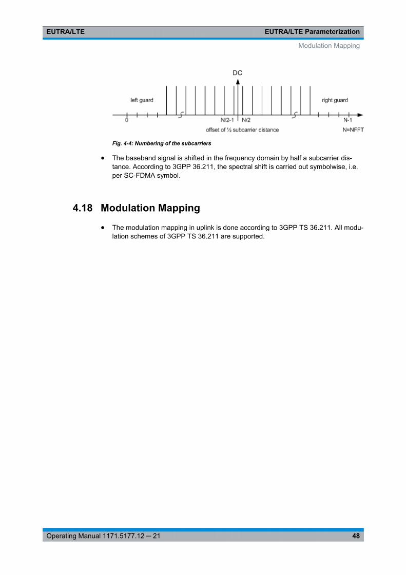
EUTRA/LTE ParameterizationEUTRA/LTE
48Operating Manual 1171.5177.12 ─ 21
Fig. 4-4: Numbering of the subcarriers
● The baseband signal is shifted in the frequency domain by half a subcarrier dis-tance. According to 3GPP 36.211, the spectral shift is carried out symbolwise, i.e.per SC-FDMA symbol.
4.18 Modulation Mapping
● The modulation mapping in uplink is done according to 3GPP TS 36.211. All modu-lation schemes of 3GPP TS 36.211 are supported.
Modulation Mapping
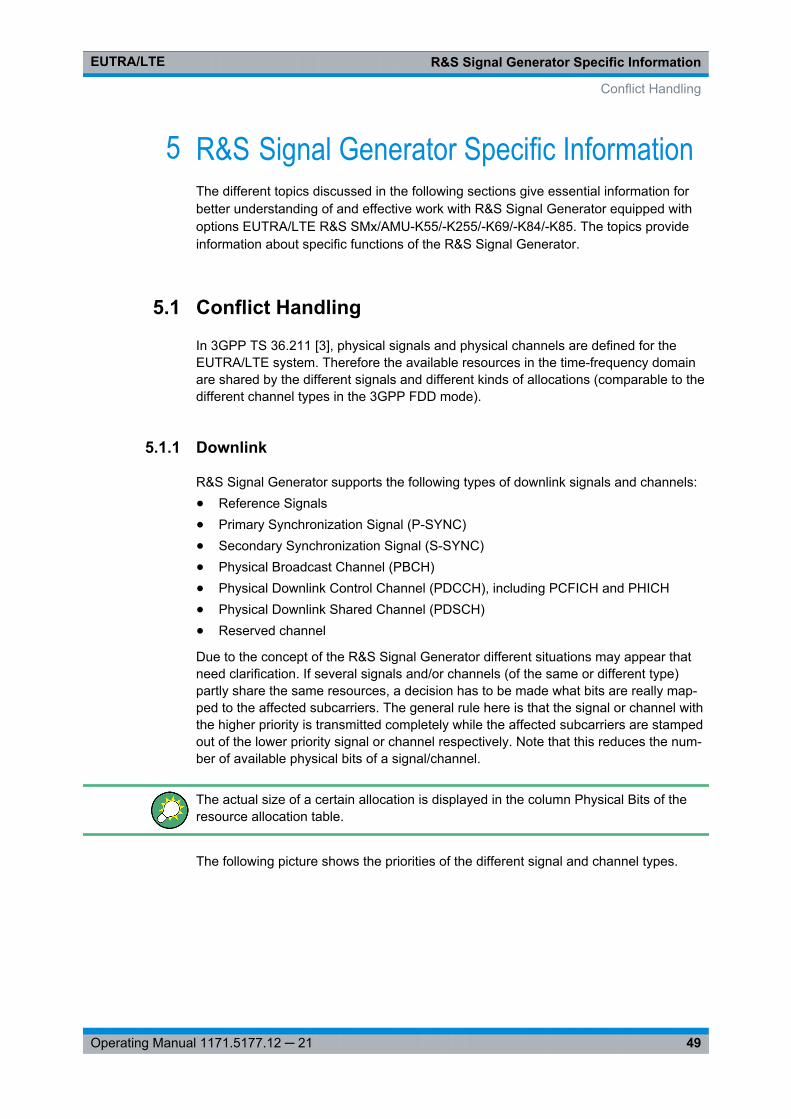
R&S Signal Generator Specific InformationEUTRA/LTE
49Operating Manual 1171.5177.12 ─ 21
5 R&S Signal Generator Specific InformationThe different topics discussed in the following sections give essential information forbetter understanding of and effective work with R&S Signal Generator equipped withoptions EUTRA/LTE R&S SMx/AMU-K55/-K255/-K69/-K84/-K85. The topics provideinformation about specific functions of the R&S Signal Generator.
5.1 Conflict Handling
In 3GPP TS 36.211 [3], physical signals and physical channels are defined for theEUTRA/LTE system. Therefore the available resources in the time-frequency domainare shared by the different signals and different kinds of allocations (comparable to thedifferent channel types in the 3GPP FDD mode).
5.1.1 Downlink
R&S Signal Generator supports the following types of downlink signals and channels:● Reference Signals● Primary Synchronization Signal (P-SYNC)● Secondary Synchronization Signal (S-SYNC)● Physical Broadcast Channel (PBCH)● Physical Downlink Control Channel (PDCCH), including PCFICH and PHICH● Physical Downlink Shared Channel (PDSCH)● Reserved channel
Due to the concept of the R&S Signal Generator different situations may appear thatneed clarification. If several signals and/or channels (of the same or different type)partly share the same resources, a decision has to be made what bits are really map-ped to the affected subcarriers. The general rule here is that the signal or channel withthe higher priority is transmitted completely while the affected subcarriers are stampedout of the lower priority signal or channel respectively. Note that this reduces the num-ber of available physical bits of a signal/channel.
The actual size of a certain allocation is displayed in the column Physical Bits of theresource allocation table.
The following picture shows the priorities of the different signal and channel types.
Conflict Handling
R&S Signal Generator Specific InformationEUTRA/LTE
50Operating Manual 1171.5177.12 ─ 21
Fig. 5-1: Priority of different allocations, channels and signals in the downlink
● Overlapping of signals and/or channels with different prioritiesIn case signals and/or channels (like for example P-SYNC and PDSCH) of differentpriorities overlap, no conflict is displayed in the resource allocation table, as thesignal/channel with the higher priority is transmitted completely.
● Overlapping of allocations with the same priorityIf different allocations of the same priority are overlapping, the one with the lowerallocation index (i.e. which comes first) in the resource allocation table is treatedwith higher priority. In this case the reduced allocation is marked in the conflict col-umn of the resource allocation table.
There is no way to configure a signal with overlapping reference signal and P-SYNC/S-SYNC.
If PRS and MBSFN is configured to be in the same subframe, MBSFN is skipped andPRS is transmitted solely.If a PDSCH is configured to overlap partially with the PRS bandwidth in a PRS sub-frame, the PRS in these resource blocks are skipped then (see example "OverlappingPDSCH, PRS and MBSFN" on page 126).
5.1.2 Uplink
In the uplink implementation of the R&S Signal Generator you can configure differentuser equipments (UEs) to use the same physical resources. The signals of the differentUEs are simply added, but nevertheless a conflict is indicated in the resource alloca-tion table.
Although a conflict is also displayed if the PUSCH and PUCCH allocations of one UEare overlapping, the signals of both allocations are added. However, a conflict can
Conflict Handling
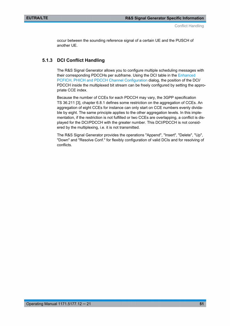
R&S Signal Generator Specific InformationEUTRA/LTE
51Operating Manual 1171.5177.12 ─ 21
occur between the sounding reference signal of a certain UE and the PUSCH ofanother UE.
5.1.3 DCI Conflict Handling
The R&S Signal Generator allows you to configure multiple scheduling messages withtheir corresponding PDCCHs per subframe. Using the DCI table in the EnhancedPCFICH, PHICH and PDCCH Channel Configuration dialog, the position of the DCI/PDCCH inside the multiplexed bit stream can be freely configured by setting the appro-priate CCE index.
Because the number of CCEs for each PDCCH may vary, the 3GPP specificationTS 36.211 [3], chapter 6.8.1 defines some restriction on the aggregation of CCEs. Anaggregation of eight CCEs for instance can only start on CCE numbers evenly divida-ble by eight. The same principle applies to the other aggregation levels. In this imple-mentation, if the restriction is not fulfilled or two CCEs are overlapping, a conflict is dis-played for the DCI/PDCCH with the greater number. This DCI/PDCCH is not consid-ered by the multiplexing, i.e. it is not transmitted.
The R&S Signal Generator provides the operations "Append", "Insert", "Delete", "Up","Down" and "Resolve Conf." for flexibly configuration of valid DCIs and for resolving ofconflicts.
Conflict Handling
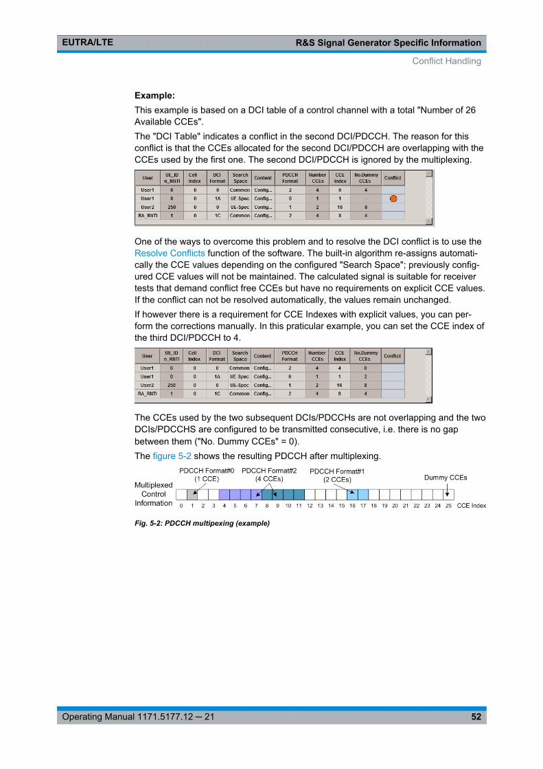
R&S Signal Generator Specific InformationEUTRA/LTE
52Operating Manual 1171.5177.12 ─ 21
Example: This example is based on a DCI table of a control channel with a total "Number of 26Available CCEs".The "DCI Table" indicates a conflict in the second DCI/PDCCH. The reason for thisconflict is that the CCEs allocated for the second DCI/PDCCH are overlapping with theCCEs used by the first one. The second DCI/PDCCH is ignored by the multiplexing.
One of the ways to overcome this problem and to resolve the DCI conflict is to use theResolve Conflicts function of the software. The built-in algorithm re-assigns automati-cally the CCE values depending on the configured "Search Space"; previously config-ured CCE values will not be maintained. The calculated signal is suitable for receivertests that demand conflict free CCEs but have no requirements on explicit CCE values.If the conflict can not be resolved automatically, the values remain unchanged.If however there is a requirement for CCE Indexes with explicit values, you can per-form the corrections manually. In this praticular example, you can set the CCE index ofthe third DCI/PDCCH to 4.
The CCEs used by the two subsequent DCIs/PDCCHs are not overlapping and the twoDCIs/PDCCHS are configured to be transmitted consecutive, i.e. there is no gapbetween them ("No. Dummy CCEs" = 0).The figure 5-2 shows the resulting PDCCH after multiplexing.
Fig. 5-2: PDCCH multipexing (example)
Conflict Handling
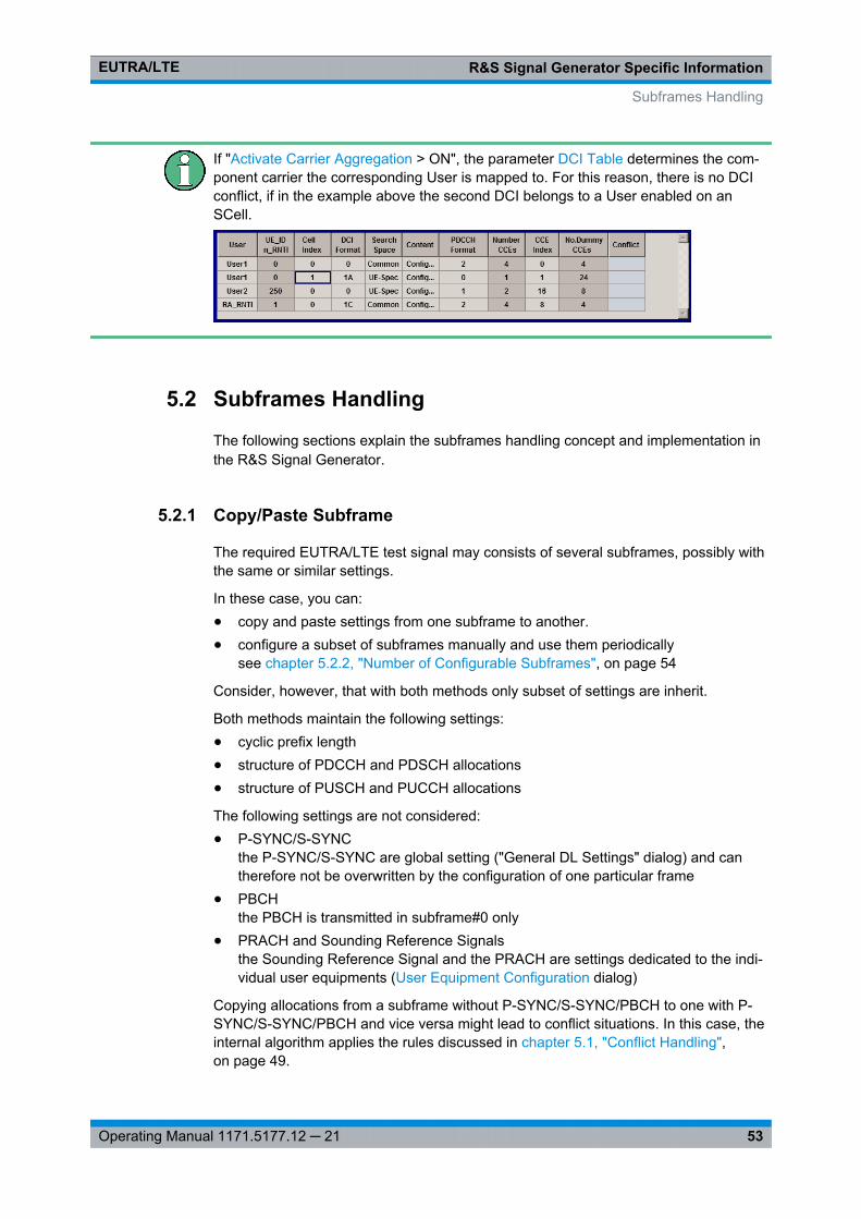
R&S Signal Generator Specific InformationEUTRA/LTE
53Operating Manual 1171.5177.12 ─ 21
If "Activate Carrier Aggregation > ON", the parameter DCI Table determines the com-ponent carrier the corresponding User is mapped to. For this reason, there is no DCIconflict, if in the example above the second DCI belongs to a User enabled on anSCell.
5.2 Subframes Handling
The following sections explain the subframes handling concept and implementation inthe R&S Signal Generator.
5.2.1 Copy/Paste Subframe
The required EUTRA/LTE test signal may consists of several subframes, possibly withthe same or similar settings.
In these case, you can:● copy and paste settings from one subframe to another.● configure a subset of subframes manually and use them periodically
see chapter 5.2.2, "Number of Configurable Subframes", on page 54
Consider, however, that with both methods only subset of settings are inherit.
Both methods maintain the following settings:● cyclic prefix length● structure of PDCCH and PDSCH allocations● structure of PUSCH and PUCCH allocations
The following settings are not considered:● P-SYNC/S-SYNC
the P-SYNC/S-SYNC are global setting ("General DL Settings" dialog) and cantherefore not be overwritten by the configuration of one particular frame
● PBCHthe PBCH is transmitted in subframe#0 only
● PRACH and Sounding Reference Signalsthe Sounding Reference Signal and the PRACH are settings dedicated to the indi-vidual user equipments (User Equipment Configuration dialog)
Copying allocations from a subframe without P-SYNC/S-SYNC/PBCH to one with P-SYNC/S-SYNC/PBCH and vice versa might lead to conflict situations. In this case, theinternal algorithm applies the rules discussed in chapter 5.1, "Conflict Handling",on page 49.
Subframes Handling
R&S Signal Generator Specific InformationEUTRA/LTE
54Operating Manual 1171.5177.12 ─ 21
However, configurations can occur where in different subframes allocations which areidentical by means of scheduled resource blocks have a different amount of physicalbits available, due to the out stamping of overlapping subcarriers.
5.2.2 Number of Configurable Subframes
As discrabed in chapter 5.2.1, "Copy/Paste Subframe", on page 53, you can simplifythe configation of the EUTRA/LTE test signal if you define a small number of sub-frames manually ("Number of Configurable Subframes") and use them periodically.
Internally, the R&S Signal Generator applies the Copy/Paste Subframe functionalityand the same subset of settings are inherit.
5.2.3 Four Configurable Frames in Uplink and Downlink Direction
The R&S Signal Generator supports the configuration of up to four frames in uplink anddownlink direction. However, there is a limitation for the maximum number of the realconfigurable subframes in this four frames depending on the transmission direction andseveral other parameters.
5.2.3.1 Uplink Direction
In uplink direction, the maximum number of the real configurable uplink subframesdepends on the selected Duplexing mode (TDD or FDD), TDD Frame Structure Set-tings and whether chapter 7.15.3, "Realtime Feedback Configuration Settings",on page 220 is enabled or not.
The maximum number of configurable subframes changes as function of the parame-ters in the following way:● For Disabled Realtime Feedback
– In FDD duplexing mode, the maximum number of configurable subframes is 40subframes, where the maximum number of 40 subframes is available forsequence lengths of at least four frames
– In a TDD frame only the uplink subframes are enabled for configuration. Themaximum number of the configurable subframes is determined by the selected"UL/DL Configuration" and the possible values are listed in the correspondingcolumn in the cross-reference table below.
● For Enabled Realtime FeedbackThe maximum number of configurable uplink subframes for the PUSCH channel ofthe first user equipment (UE 1) is determined by the "Number of HARQ Pro-cesses", that itself also depends on the duplexing mode and the UL/DL configura-tion.For an overview of the possible values, see the corresponding column in the cross-reference table 5-1.
The current subframe to be configured is selected by means of the parameter Sub-frame.
Subframes Handling
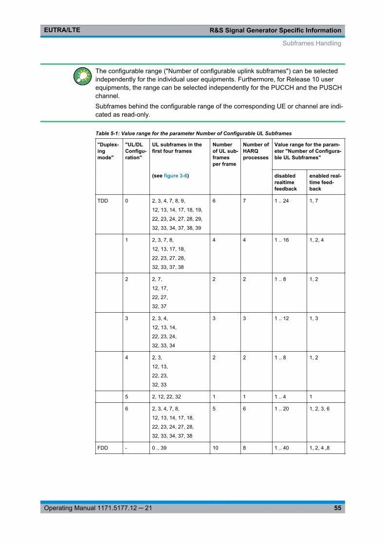
R&S Signal Generator Specific InformationEUTRA/LTE
55Operating Manual 1171.5177.12 ─ 21
The configurable range ("Number of configurable uplink subframes") can be selectedindependently for the individual user equipments. Furthermore, for Release 10 userequipments, the range can be selected independently for the PUCCH and the PUSCHchannel.Subframes behind the configurable range of the corresponding UE or channel are indi-cated as read-only.
Table 5-1: Value range for the parameter Number of Configurable UL Subframes
"Duplex-ingmode"
"UL/DLConfigu-ration"
UL subframes in thefirst four frames
Numberof UL sub-framesper frame
Number ofHARQprocesses
Value range for the param-eter "Number of Configura-ble UL Subframes"
(see figure 3-6) disabledrealtimefeedback
enabled real-time feed-back
TDD 0 2, 3, 4, 7, 8, 9,
12, 13, 14, 17, 18, 19,
22, 23, 24, 27, 28, 29,
32, 33, 34, 37, 38, 39
6 7 1 .. 24 1, 7
1 2, 3, 7, 8,
12, 13, 17, 18,
22, 23, 27, 28,
32, 33, 37, 38
4 4 1 .. 16 1, 2, 4
2 2, 7,
12, 17,
22, 27,
32, 37
2 2 1 .. 8 1, 2
3 2, 3, 4,
12, 13, 14,
22, 23, 24,
32, 33, 34
3 3 1 .. 12 1, 3
4 2, 3,
12, 13,
22, 23,
32, 33
2 2 1 .. 8 1, 2
5 2, 12, 22, 32 1 1 1 .. 4 1
6 2, 3, 4, 7, 8,
12, 13, 14, 17, 18,
22, 23, 24, 27, 28,
32, 33, 34, 37, 38
5 6 1 .. 20 1, 2, 3, 6
FDD - 0 .. 39 10 8 1 .. 40 1, 2, 4 ,8
Subframes Handling
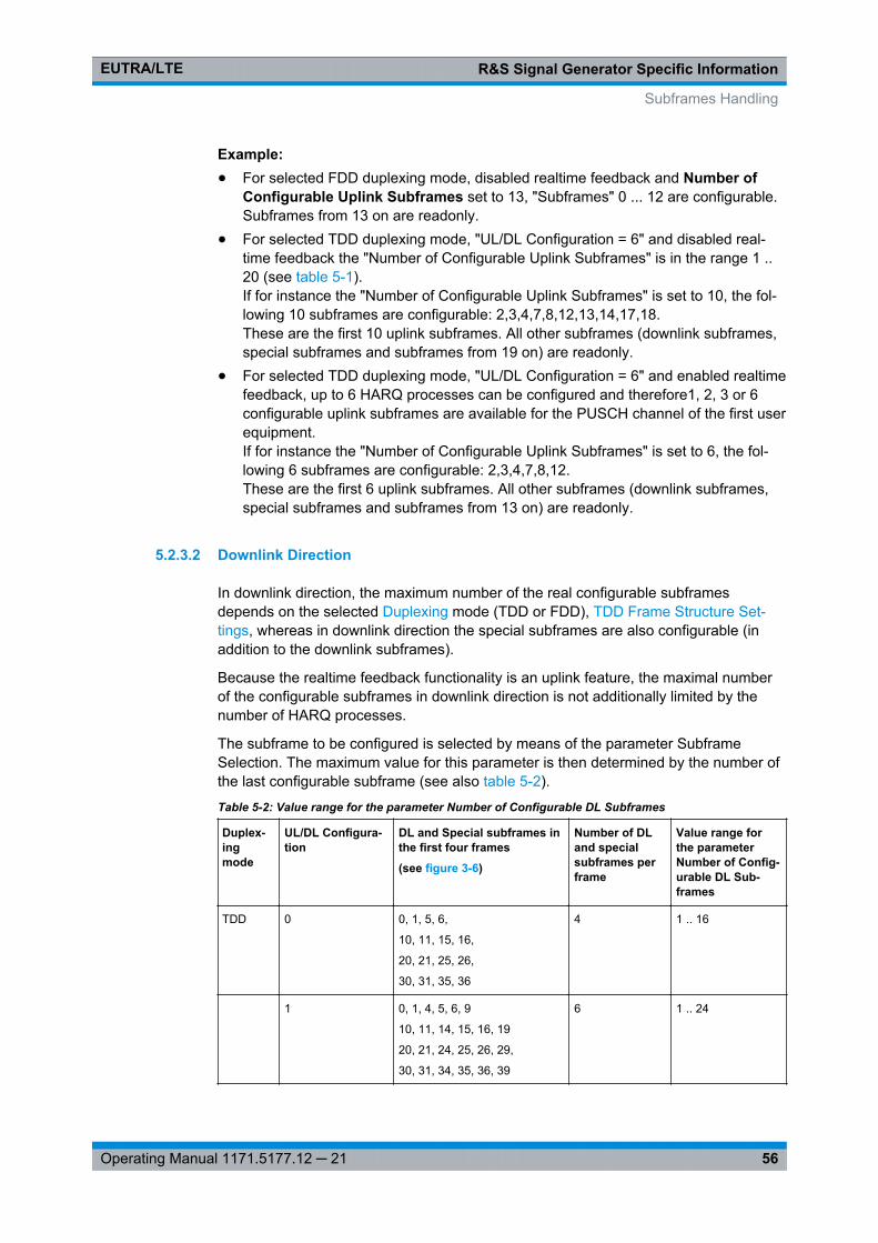
R&S Signal Generator Specific InformationEUTRA/LTE
56Operating Manual 1171.5177.12 ─ 21
Example: ● For selected FDD duplexing mode, disabled realtime feedback and Number of
Configurable Uplink Subframes set to 13, "Subframes" 0 ... 12 are configurable.Subframes from 13 on are readonly.
● For selected TDD duplexing mode, "UL/DL Configuration = 6" and disabled real-time feedback the "Number of Configurable Uplink Subframes" is in the range 1 ..20 (see table 5-1).If for instance the "Number of Configurable Uplink Subframes" is set to 10, the fol-lowing 10 subframes are configurable: 2,3,4,7,8,12,13,14,17,18.These are the first 10 uplink subframes. All other subframes (downlink subframes,special subframes and subframes from 19 on) are readonly.
● For selected TDD duplexing mode, "UL/DL Configuration = 6" and enabled realtimefeedback, up to 6 HARQ processes can be configured and therefore1, 2, 3 or 6configurable uplink subframes are available for the PUSCH channel of the first userequipment.If for instance the "Number of Configurable Uplink Subframes" is set to 6, the fol-lowing 6 subframes are configurable: 2,3,4,7,8,12.These are the first 6 uplink subframes. All other subframes (downlink subframes,special subframes and subframes from 13 on) are readonly.
5.2.3.2 Downlink Direction
In downlink direction, the maximum number of the real configurable subframesdepends on the selected Duplexing mode (TDD or FDD), TDD Frame Structure Set-tings, whereas in downlink direction the special subframes are also configurable (inaddition to the downlink subframes).
Because the realtime feedback functionality is an uplink feature, the maximal numberof the configurable subframes in downlink direction is not additionally limited by thenumber of HARQ processes.
The subframe to be configured is selected by means of the parameter SubframeSelection. The maximum value for this parameter is then determined by the number ofthe last configurable subframe (see also table 5-2).
Table 5-2: Value range for the parameter Number of Configurable DL Subframes
Duplex-ingmode
UL/DL Configura-tion
DL and Special subframes inthe first four frames
(see figure 3-6)
Number of DLand specialsubframes perframe
Value range forthe parameterNumber of Config-urable DL Sub-frames
TDD 0 0, 1, 5, 6,
10, 11, 15, 16,
20, 21, 25, 26,
30, 31, 35, 36
4 1 .. 16
1 0, 1, 4, 5, 6, 9
10, 11, 14, 15, 16, 19
20, 21, 24, 25, 26, 29,
30, 31, 34, 35, 36, 39
6 1 .. 24
Subframes Handling
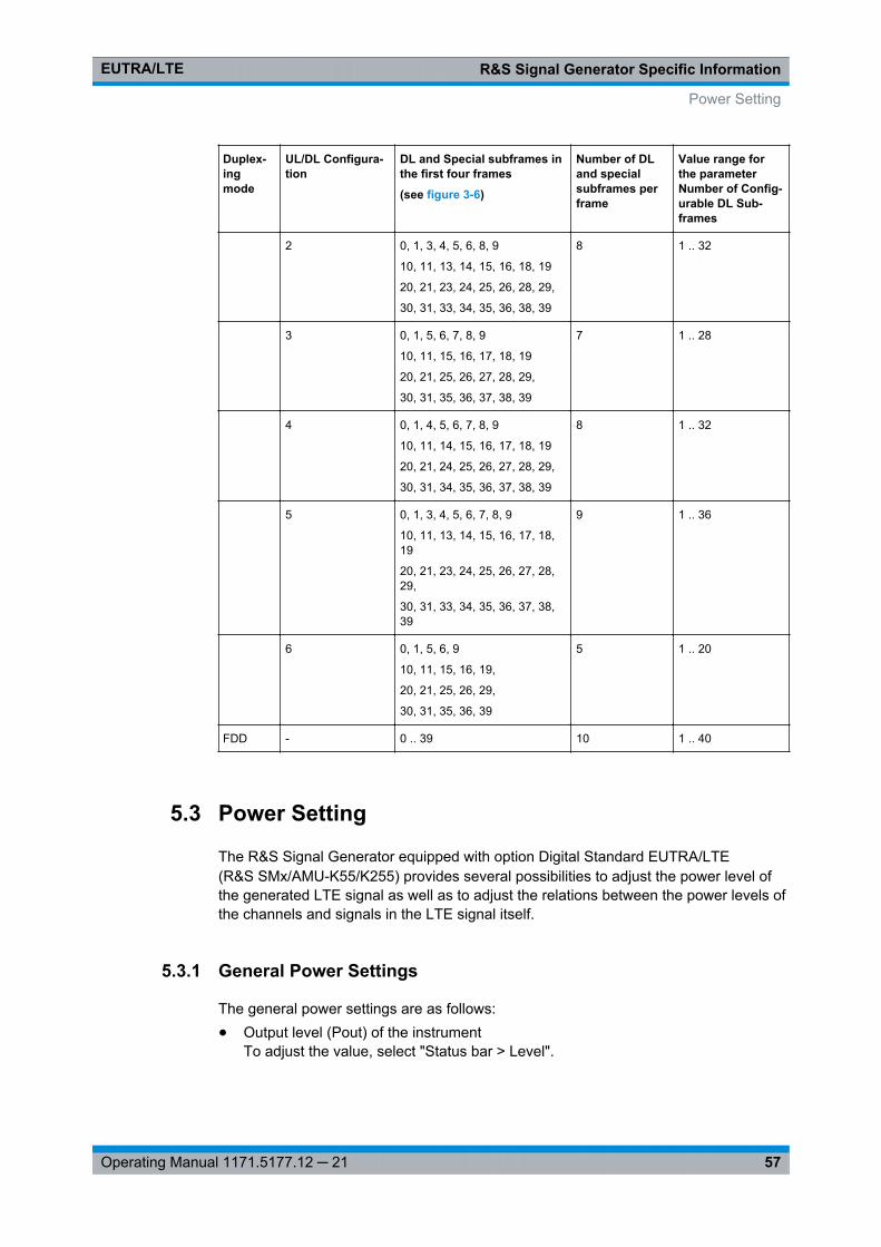
R&S Signal Generator Specific InformationEUTRA/LTE
57Operating Manual 1171.5177.12 ─ 21
Duplex-ingmode
UL/DL Configura-tion
DL and Special subframes inthe first four frames
(see figure 3-6)
Number of DLand specialsubframes perframe
Value range forthe parameterNumber of Config-urable DL Sub-frames
2 0, 1, 3, 4, 5, 6, 8, 9
10, 11, 13, 14, 15, 16, 18, 19
20, 21, 23, 24, 25, 26, 28, 29,
30, 31, 33, 34, 35, 36, 38, 39
8 1 .. 32
3 0, 1, 5, 6, 7, 8, 9
10, 11, 15, 16, 17, 18, 19
20, 21, 25, 26, 27, 28, 29,
30, 31, 35, 36, 37, 38, 39
7 1 .. 28
4 0, 1, 4, 5, 6, 7, 8, 9
10, 11, 14, 15, 16, 17, 18, 19
20, 21, 24, 25, 26, 27, 28, 29,
30, 31, 34, 35, 36, 37, 38, 39
8 1 .. 32
5 0, 1, 3, 4, 5, 6, 7, 8, 9
10, 11, 13, 14, 15, 16, 17, 18,19
20, 21, 23, 24, 25, 26, 27, 28,29,
30, 31, 33, 34, 35, 36, 37, 38,39
9 1 .. 36
6 0, 1, 5, 6, 9
10, 11, 15, 16, 19,
20, 21, 25, 26, 29,
30, 31, 35, 36, 39
5 1 .. 20
FDD - 0 .. 39 10 1 .. 40
5.3 Power Setting
The R&S Signal Generator equipped with option Digital Standard EUTRA/LTE(R&S SMx/AMU-K55/K255) provides several possibilities to adjust the power level ofthe generated LTE signal as well as to adjust the relations between the power levels ofthe channels and signals in the LTE signal itself.
5.3.1 General Power Settings
The general power settings are as follows:● Output level (Pout) of the instrument
To adjust the value, select "Status bar > Level".
Power Setting
R&S Signal Generator Specific InformationEUTRA/LTE
58Operating Manual 1171.5177.12 ─ 21
● Power Offset Relative to Level Display is a parameter related to the level of the sig-nal at the output of the baseband part of the instrument. The parameter sets therelative power offset of the selected baseband path compared to the power leveldisplayed in the header of the instrument. A value of 0 dB refers to the level set inthe main "Level" settings; a negative value lowers the level of the selected base-band.Use this parameter to adjust the baseband output power compared to the base-band power of the other baseband if the performed test case requires the signalsof UEs with different SNR and the same AWGN block is used. An example of sucha test scenario are the Multi user PUCCH tests as defined in the 3GPP specifica-tion TS 36.141.
5.3.2 Downlink Power Settings
In downlink direction, the value displayed in the "Level" display defines the RMS levelof the output signal calculated upon several frames. In the FDD duplexing mode, thedisplayed RMS and the PEP values are valid for the whole frame, while in TDD duplex-ing mode, the calculation is based only on the downlink parts of the frame, i.e. the DLsubframes and the DwPTS (see also parameter "Power Reference" on page 258).
Additionally to the general power settings, the following settings are influencing thepower of the output signal in downlink direction:● Downlink Reference Signal Structure● Synchronization Signal Settings, Synchronization Signal Settings● PBCH Power and PDSCH Power● PCFICH Settings,PHICH Settings , PDCCH Settings● Cell Specific Settings (Cell Specific Settings) and Cell Specific Settings
All DL power configurations are set relative to each other and the absolute power levelof one resource element during one sub-frame depends on the configuration during theremaining sub-frames. If for instance the PDCCH power is set to 2 dB and a certainPDSCH has a power of -3 dB, this means that the power level of the PDCCH sub-carri-ers is with 5 dB higher than the power level of the PDSCH sub-carriers.
The basis for the calculation of the absolute power level of the channels and the sig-nals in DL direction is the power of one reference signal resource element. The valueis displayed in the General DL Settings dialog by means of the parameter DownlinkReference Signal Structure. Use this parameter to configure a specific absolute powerof one Reference Signal's sub-carrier, like for example to set a required SNR definedfor a 15kHz sub-band.
To calculate the absolute power value of one single Reference Signal sub-carrier, con-sider the general power settings and the relative RS Power.
Power Setting
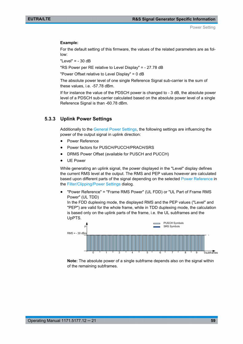
R&S Signal Generator Specific InformationEUTRA/LTE
59Operating Manual 1171.5177.12 ─ 21
Example: For the default setting of this firmware, the values of the related parameters are as fol-low:"Level" = - 30 dB"RS Power per RE relative to Level Display" = - 27.78 dB"Power Offset relative to Level Display" = 0 dBThe absolute power level of one single Reference Signal sub-carrier is the sum ofthese values, i.e. -57.78 dBm.If for instance the value of the PDSCH power is changed to - 3 dB, the absolute powerlevel of a PDSCH sub-carrier calculated based on the absolute power level of a singleReference Signal is than -60.78 dBm.
5.3.3 Uplink Power Settings
Additionally to the General Power Settings, the following settings are influencing thepower of the output signal in uplink direction:● Power Reference● Power factors for PUSCH/PUCCH/PRACH/SRS● DRMS Power Offset (available for PUSCH and PUCCH)● UE Power
While generating an uplink signal, the power displayed in the "Level" display definesthe current RMS level at the output. The RMS and PEP values however are calculatedbased upon different parts of the signal depending on the selected Power Reference inthe Filter/Clipping/Power Settings dialog.
● "Power Reference" = "Frame RMS Power" (UL FDD) or "UL Part of Frame RMSPower" (UL TDD)In the FDD duplexing mode, the displayed RMS and the PEP values ("Level" and"PEP") are valid for the whole frame, while in TDD duplexing mode, the calculationis based only on the uplink parts of the frame, i.e. the UL subframes and theUpPTS.
Note: The absolute power of a single subframe depends also on the signal withinof the remaining subframes.
Power Setting
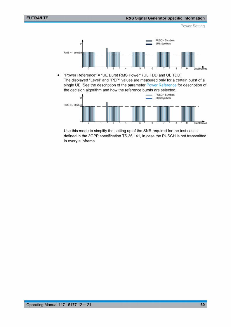
R&S Signal Generator Specific InformationEUTRA/LTE
60Operating Manual 1171.5177.12 ─ 21
● "Power Reference" = "UE Burst RMS Power" (UL FDD and UL TDD)The displayed "Level" and "PEP" values are measured only for a certain burst of asingle UE. See the description of the parameter Power Reference for description ofthe decision algorithm and how the reference bursts are selected.
Use this mode to simplify the setting up of the SNR required for the test casesdefined in the 3GPP specification TS 36.141, in case the PUSCH is not transmittedin every subframe.
Power Setting
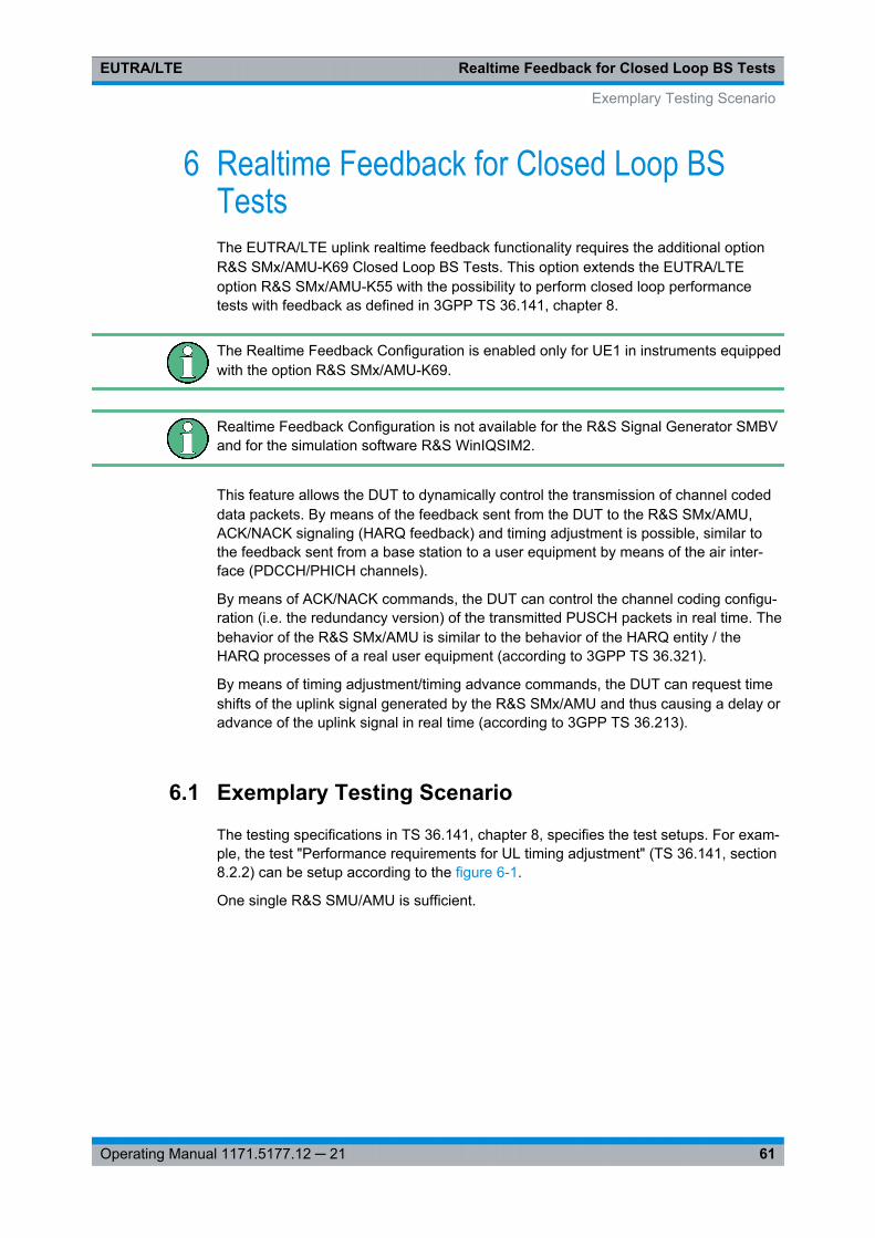
Realtime Feedback for Closed Loop BS TestsEUTRA/LTE
61Operating Manual 1171.5177.12 ─ 21
6 Realtime Feedback for Closed Loop BSTestsThe EUTRA/LTE uplink realtime feedback functionality requires the additional optionR&S SMx/AMU-K69 Closed Loop BS Tests. This option extends the EUTRA/LTEoption R&S SMx/AMU-K55 with the possibility to perform closed loop performancetests with feedback as defined in 3GPP TS 36.141, chapter 8.
The Realtime Feedback Configuration is enabled only for UE1 in instruments equippedwith the option R&S SMx/AMU-K69.
Realtime Feedback Configuration is not available for the R&S Signal Generator SMBVand for the simulation software R&S WinIQSIM2.
This feature allows the DUT to dynamically control the transmission of channel codeddata packets. By means of the feedback sent from the DUT to the R&S SMx/AMU,ACK/NACK signaling (HARQ feedback) and timing adjustment is possible, similar tothe feedback sent from a base station to a user equipment by means of the air inter-face (PDCCH/PHICH channels).
By means of ACK/NACK commands, the DUT can control the channel coding configu-ration (i.e. the redundancy version) of the transmitted PUSCH packets in real time. Thebehavior of the R&S SMx/AMU is similar to the behavior of the HARQ entity / theHARQ processes of a real user equipment (according to 3GPP TS 36.321).
By means of timing adjustment/timing advance commands, the DUT can request timeshifts of the uplink signal generated by the R&S SMx/AMU and thus causing a delay oradvance of the uplink signal in real time (according to 3GPP TS 36.213).
6.1 Exemplary Testing Scenario
The testing specifications in TS 36.141, chapter 8, specifies the test setups. For exam-ple, the test "Performance requirements for UL timing adjustment" (TS 36.141, section8.2.2) can be setup according to the figure 6-1.
One single R&S SMU/AMU is sufficient.
Exemplary Testing Scenario
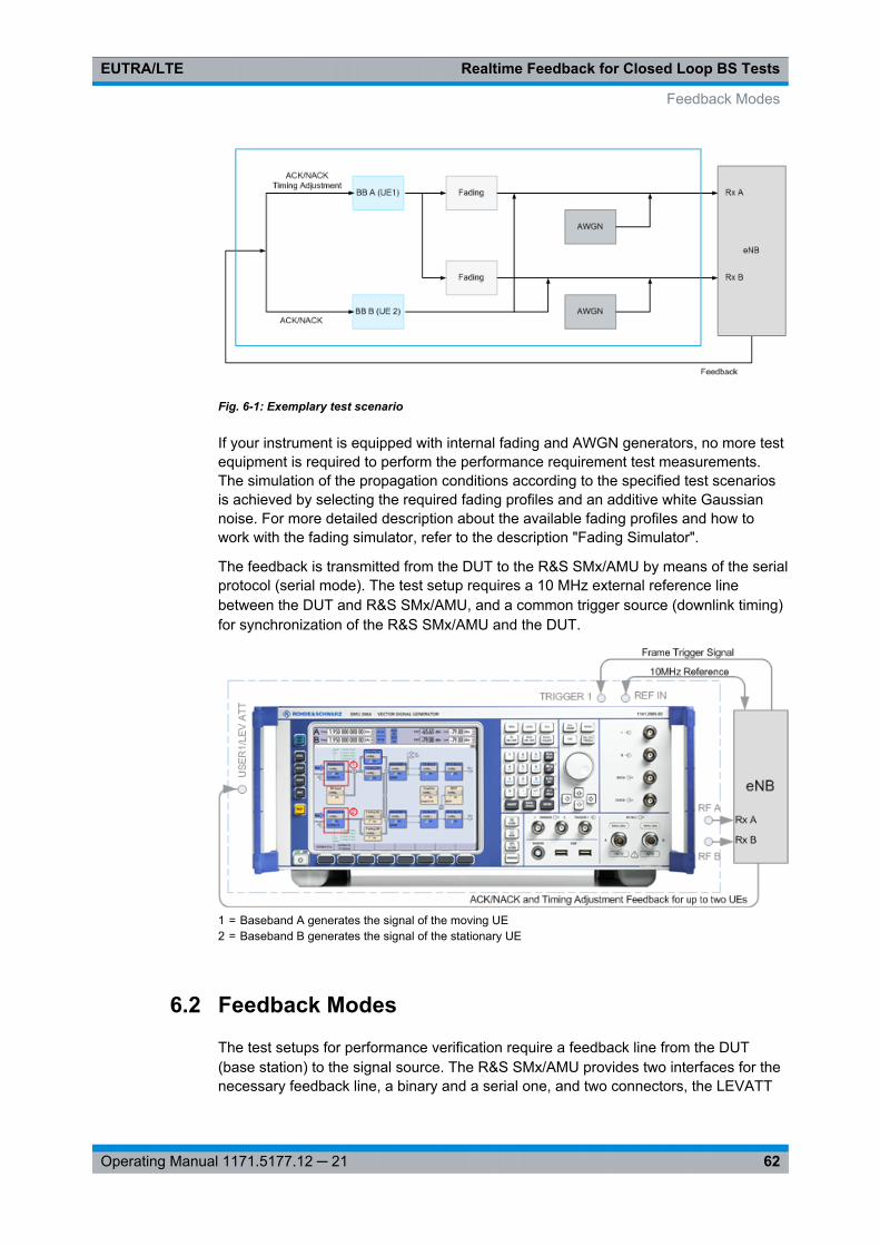
Realtime Feedback for Closed Loop BS TestsEUTRA/LTE
62Operating Manual 1171.5177.12 ─ 21
Fig. 6-1: Exemplary test scenario
If your instrument is equipped with internal fading and AWGN generators, no more testequipment is required to perform the performance requirement test measurements.The simulation of the propagation conditions according to the specified test scenariosis achieved by selecting the required fading profiles and an additive white Gaussiannoise. For more detailed description about the available fading profiles and how towork with the fading simulator, refer to the description "Fading Simulator".
The feedback is transmitted from the DUT to the R&S SMx/AMU by means of the serialprotocol (serial mode). The test setup requires a 10 MHz external reference linebetween the DUT and R&S SMx/AMU, and a common trigger source (downlink timing)for synchronization of the R&S SMx/AMU and the DUT.
1 = Baseband A generates the signal of the moving UE2 = Baseband B generates the signal of the stationary UE
6.2 Feedback Modes
The test setups for performance verification require a feedback line from the DUT(base station) to the signal source. The R&S SMx/AMU provides two interfaces for thenecessary feedback line, a binary and a serial one, and two connectors, the LEVATT
Feedback Modes
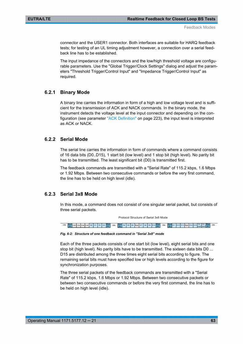
Realtime Feedback for Closed Loop BS TestsEUTRA/LTE
63Operating Manual 1171.5177.12 ─ 21
connector and the USER1 connector. Both interfaces are suitable for HARQ feedbacktests; for testing of an UL timing adjustment however, a connection over a serial feed-back line has to be established.
The input impedance of the connectors and the low/high threshold voltage are configu-rable parameters. Use the "Global Trigger/Clock Settings" dialog and adjust the param-eters "Threshold Trigger/Control Input" and "Impedance Trigger/Control Input" asrequired.
6.2.1 Binary Mode
A binary line carries the information in form of a high and low voltage level and is suffi-cient for the transmission of ACK and NACK commands. In the binary mode, theinstrument detects the voltage level at the input connector and depending on the con-figuration (see parameter "ACK Definition" on page 223), the input level is interpretedas ACK or NACK.
6.2.2 Serial Mode
The serial line carries the information in form of commands where a command consistsof 16 data bits (D0..D15), 1 start bit (low level) and 1 stop bit (high level). No parity bithas to be transmitted. The least significant bit (D0) is transmitted first.
The feedback commands are transmitted with a "Serial Rate" of 115.2 kbps, 1.6 Mbpsor 1.92 Mbps. Between two consecutive commands or before the very first command,the line has to be held on high level (idle).
6.2.3 Serial 3x8 Mode
In this mode, a command does not consist of one singular serial packet, but consists ofthree serial packets.
Fig. 6-2: Structure of one feedback command in "Serial 3x8" mode
Each of the three packets consists of one start bit (low level), eight serial bits and onestop bit (high level). No parity bits have to be transmitted. The sixteen data bits D0 ...D15 are distributed among the three times eight serial bits according to figure. Theremaining serial bits must have specified low or high levels according to the figure forsynchronization purposes.
The three serial packets of the feedback commands are transmitted with a "SerialRate" of 115.2 kbps, 1.6 Mbps or 1.92 Mbps. Between two consecutive packets orbetween two consecutive commands or before the very first command, the line has tobe held on high level (idle).
Feedback Modes
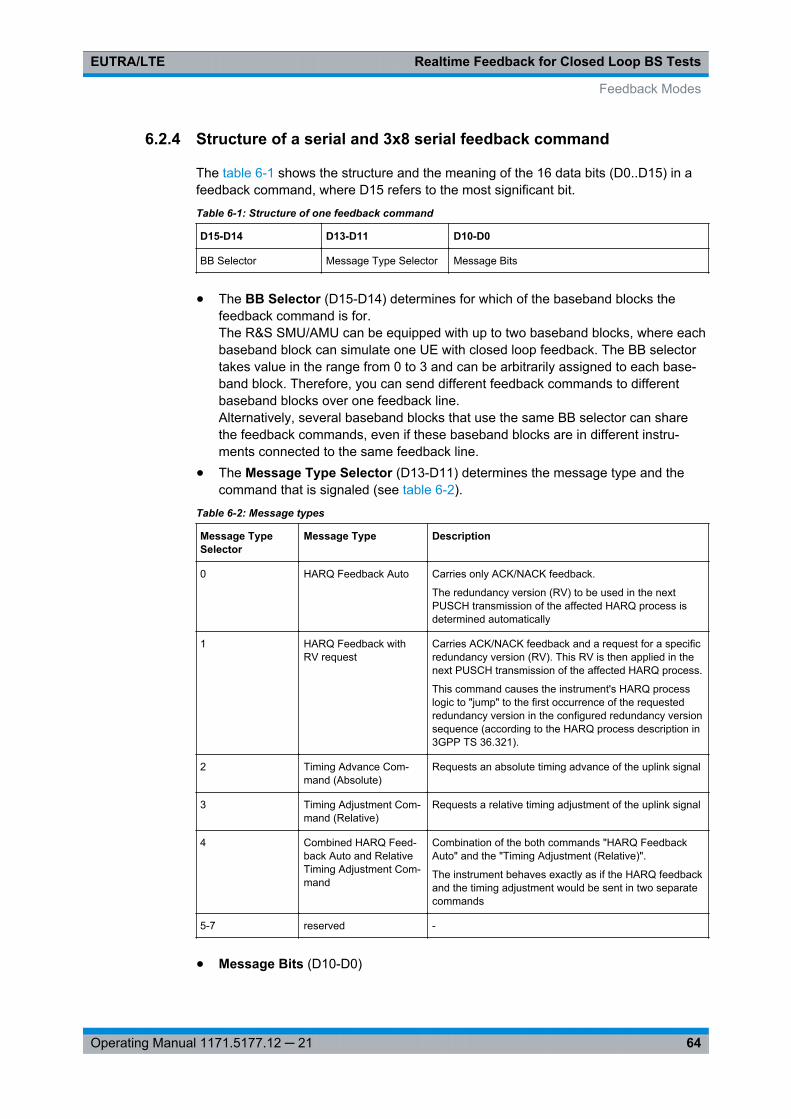
Realtime Feedback for Closed Loop BS TestsEUTRA/LTE
64Operating Manual 1171.5177.12 ─ 21
6.2.4 Structure of a serial and 3x8 serial feedback command
The table 6-1 shows the structure and the meaning of the 16 data bits (D0..D15) in afeedback command, where D15 refers to the most significant bit.
Table 6-1: Structure of one feedback command
D15-D14 D13-D11 D10-D0
BB Selector Message Type Selector Message Bits
● The BB Selector (D15-D14) determines for which of the baseband blocks thefeedback command is for.The R&S SMU/AMU can be equipped with up to two baseband blocks, where eachbaseband block can simulate one UE with closed loop feedback. The BB selectortakes value in the range from 0 to 3 and can be arbitrarily assigned to each base-band block. Therefore, you can send different feedback commands to differentbaseband blocks over one feedback line.Alternatively, several baseband blocks that use the same BB selector can sharethe feedback commands, even if these baseband blocks are in different instru-ments connected to the same feedback line.
● The Message Type Selector (D13-D11) determines the message type and thecommand that is signaled (see table 6-2).
Table 6-2: Message types
Message TypeSelector
Message Type Description
0 HARQ Feedback Auto Carries only ACK/NACK feedback.
The redundancy version (RV) to be used in the nextPUSCH transmission of the affected HARQ process isdetermined automatically
1 HARQ Feedback withRV request
Carries ACK/NACK feedback and a request for a specificredundancy version (RV). This RV is then applied in thenext PUSCH transmission of the affected HARQ process.
This command causes the instrument's HARQ processlogic to "jump" to the first occurrence of the requestedredundancy version in the configured redundancy versionsequence (according to the HARQ process description in3GPP TS 36.321).
2 Timing Advance Com-mand (Absolute)
Requests an absolute timing advance of the uplink signal
3 Timing Adjustment Com-mand (Relative)
Requests a relative timing adjustment of the uplink signal
4 Combined HARQ Feed-back Auto and RelativeTiming Adjustment Com-mand
Combination of the both commands "HARQ FeedbackAuto" and the "Timing Adjustment (Relative)".
The instrument behaves exactly as if the HARQ feedbackand the timing adjustment would be sent in two separatecommands
5-7 reserved -
● Message Bits (D10-D0)
Feedback Modes
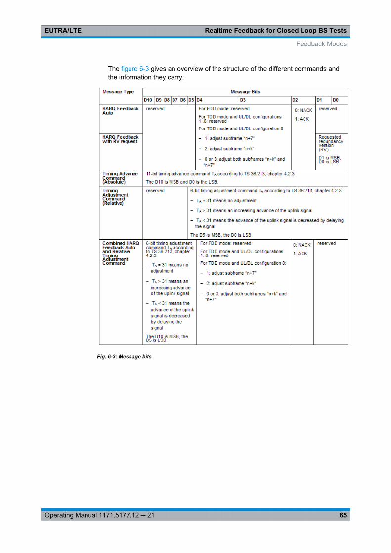
Realtime Feedback for Closed Loop BS TestsEUTRA/LTE
65Operating Manual 1171.5177.12 ─ 21
The figure 6-3 gives an overview of the structure of the different commands andthe information they carry.
Fig. 6-3: Message bits
Feedback Modes
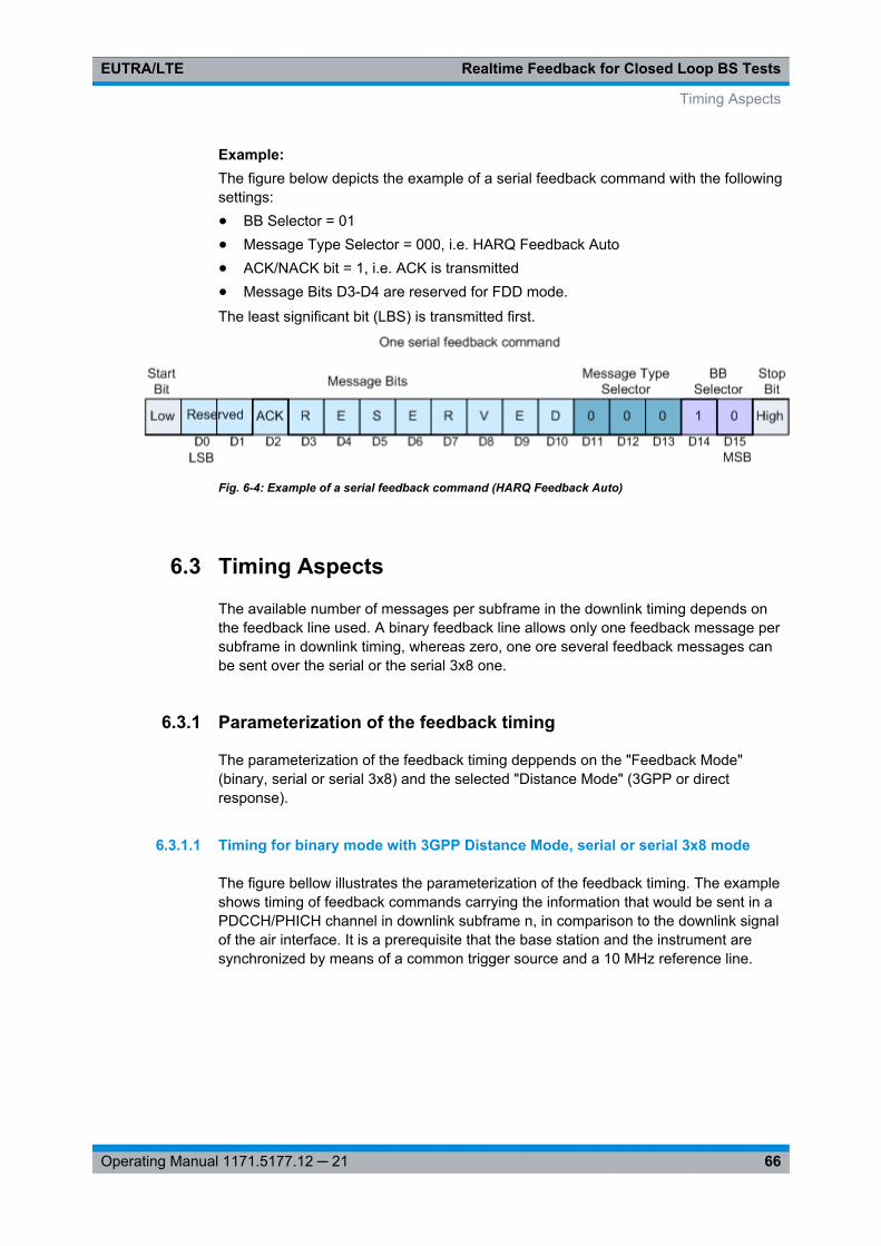
Realtime Feedback for Closed Loop BS TestsEUTRA/LTE
66Operating Manual 1171.5177.12 ─ 21
Example: The figure below depicts the example of a serial feedback command with the followingsettings:● BB Selector = 01● Message Type Selector = 000, i.e. HARQ Feedback Auto● ACK/NACK bit = 1, i.e. ACK is transmitted● Message Bits D3-D4 are reserved for FDD mode.
The least significant bit (LBS) is transmitted first.
Fig. 6-4: Example of a serial feedback command (HARQ Feedback Auto)
6.3 Timing Aspects
The available number of messages per subframe in the downlink timing depends onthe feedback line used. A binary feedback line allows only one feedback message persubframe in downlink timing, whereas zero, one ore several feedback messages canbe sent over the serial or the serial 3x8 one.
6.3.1 Parameterization of the feedback timing
The parameterization of the feedback timing deppends on the "Feedback Mode"(binary, serial or serial 3x8) and the selected "Distance Mode" (3GPP or directresponse).
6.3.1.1 Timing for binary mode with 3GPP Distance Mode, serial or serial 3x8 mode
The figure bellow illustrates the parameterization of the feedback timing. The exampleshows timing of feedback commands carrying the information that would be sent in aPDCCH/PHICH channel in downlink subframe n, in comparison to the downlink signalof the air interface. It is a prerequisite that the base station and the instrument aresynchronized by means of a common trigger source and a 10 MHz reference line.
Timing Aspects
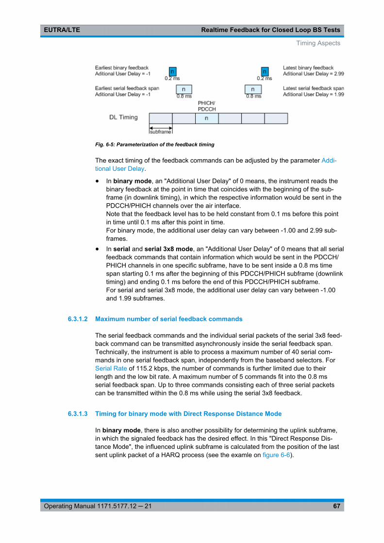
Realtime Feedback for Closed Loop BS TestsEUTRA/LTE
67Operating Manual 1171.5177.12 ─ 21
Fig. 6-5: Parameterization of the feedback timing
The exact timing of the feedback commands can be adjusted by the parameter Addi-tional User Delay.
● In binary mode, an "Additional User Delay" of 0 means, the instrument reads thebinary feedback at the point in time that coincides with the beginning of the sub-frame (in downlink timing), in which the respective information would be sent in thePDCCH/PHICH channels over the air interface.Note that the feedback level has to be held constant from 0.1 ms before this pointin time until 0.1 ms after this point in time.For binary mode, the additional user delay can vary between -1.00 and 2.99 sub-frames.
● In serial and serial 3x8 mode, an "Additional User Delay" of 0 means that all serialfeedback commands that contain information which would be sent in the PDCCH/PHICH channels in one specific subframe, have to be sent inside a 0.8 ms timespan starting 0.1 ms after the beginning of this PDCCH/PHICH subframe (downlinktiming) and ending 0.1 ms before the end of this PDCCH/PHICH subframe.For serial and serial 3x8 mode, the additional user delay can vary between -1.00and 1.99 subframes.
6.3.1.2 Maximum number of serial feedback commands
The serial feedback commands and the individual serial packets of the serial 3x8 feed-back command can be transmitted asynchronously inside the serial feedback span.Technically, the instrument is able to process a maximum number of 40 serial com-mands in one serial feedback span, independently from the baseband selectors. ForSerial Rate of 115.2 kbps, the number of commands is further limited due to theirlength and the low bit rate. A maximum number of 5 commands fit into the 0.8 msserial feedback span. Up to three commands consisting each of three serial packetscan be transmitted within the 0.8 ms while using the serial 3x8 feedback.
6.3.1.3 Timing for binary mode with Direct Response Distance Mode
In binary mode, there is also another possibility for determining the uplink subframe,in which the signaled feedback has the desired effect. In this "Direct Response Dis-tance Mode", the influenced uplink subframe is calculated from the position of the lastsent uplink packet of a HARQ process (see the examle on figure 6-6).
Timing Aspects
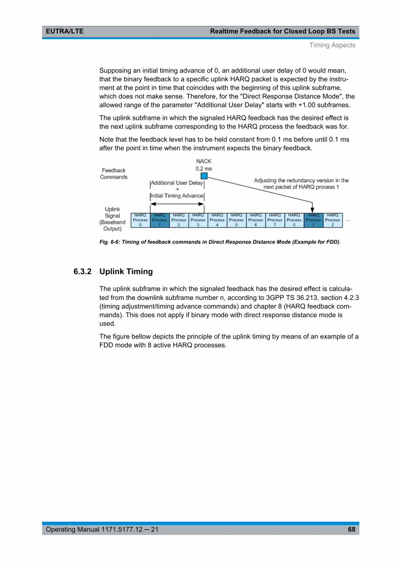
Realtime Feedback for Closed Loop BS TestsEUTRA/LTE
68Operating Manual 1171.5177.12 ─ 21
Supposing an initial timing advance of 0, an additional user delay of 0 would mean,that the binary feedback to a specific uplink HARQ packet is expected by the instru-ment at the point in time that coincides with the beginning of this uplink subframe,which does not make sense. Therefore, for the "Direct Response Distance Mode", theallowed range of the parameter "Additional User Delay" starts with +1.00 subframes.
The uplink subframe in which the signaled HARQ feedback has the desired effect isthe next uplink subframe corresponding to the HARQ process the feedback was for.
Note that the feedback level has to be held constant from 0.1 ms before until 0.1 msafter the point in time when the instrument expects the binary feedback.
Fig. 6-6: Timing of feedback commands in Direct Response Distance Mode (Example for FDD).
6.3.2 Uplink Timing
The uplink subframe in which the signaled feedback has the desired effect is calcula-ted from the downlink subframe number n, according to 3GPP TS 36.213, section 4.2.3(timing adjustment/timing advance commands) and chapter 8 (HARQ feedback com-mands). This does not apply if binary mode with direct response distance mode isused.
The figure bellow depicts the principle of the uplink timing by means of an example of aFDD mode with 8 active HARQ processes.
Timing Aspects
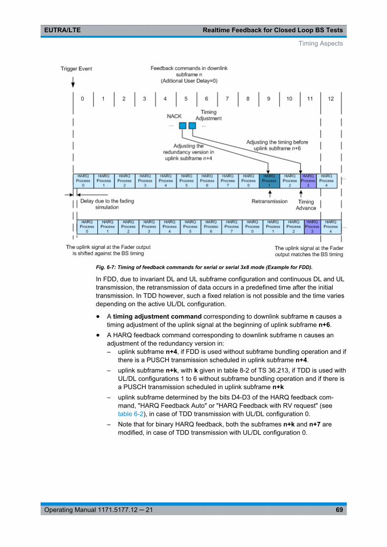
Realtime Feedback for Closed Loop BS TestsEUTRA/LTE
69Operating Manual 1171.5177.12 ─ 21
Fig. 6-7: Timing of feedback commands for serial or serial 3x8 mode (Example for FDD).
In FDD, due to invariant DL and UL subframe configuration and continuous DL and ULtransmission, the retransmission of data occurs in a predefined time after the initialtransmission. In TDD however, such a fixed relation is not possible and the time variesdepending on the active UL/DL configuration.
● A timing adjustment command corresponding to downlink subframe n causes atiming adjustment of the uplink signal at the beginning of uplink subframe n+6.
● A HARQ feedback command corresponding to downlink subframe n causes anadjustment of the redundancy version in:– uplink subframe n+4, if FDD is used without subframe bundling operation and if
there is a PUSCH transmission scheduled in uplink subframe n+4.– uplink subframe n+k, with k given in table 8-2 of TS 36.213, if TDD is used with
UL/DL configurations 1 to 6 without subframe bundling operation and if there isa PUSCH transmission scheduled in uplink subframe n+k
– uplink subframe determined by the bits D4-D3 of the HARQ feedback com-mand, "HARQ Feedback Auto" or "HARQ Feedback with RV request" (seetable 6-2), in case of TDD transmission with UL/DL configuration 0.
– Note that for binary HARQ feedback, both the subframes n+k and n+7 aremodified, in case of TDD transmission with UL/DL configuration 0.
Timing Aspects
Realtime Feedback for Closed Loop BS TestsEUTRA/LTE
70Operating Manual 1171.5177.12 ─ 21
6.3.2.1 General timing rules
The first HARQ feedback recognized by the instrument after triggering is the feedbackresponding to the first uplink PUSCH transmission. For example, if a PUSCH is sched-uled in uplink subframe 0 and if FDD without subframe bundling is used, the firstHARQ feedback recognized by the instrument is the one affecting uplink subframe 8.
If no HARQ feedback command is received for a specific HARQ process in serialmode, the instrument behaves as if NACK was signaled in a "HARQ Feedback Auto"command. If there is a conflict between several HARQ feedback commands (becausethey would affect the same uplink PUSCH transmission), only the last received HARQfeedback command is considered.
The first timing advance or timing adjustment command that is recognized by theinstrument after triggering is the one causing a timing adjustment at the beginning ofuplink subframe 8.
If no timing advance or timing adjustment command is received, then no timing adjust-ment is applied, (i.e. the timing advance in subframe n+6 will not be modified). If thereis a conflict between several timing advance or timing adjustment commands (becausethey would affect the same uplink subframe), only the last received timing advance /adjustment command is considered.
If the serial or serial 3x8 mode is used, the serial line has to be held idle (high) duringdownlink subframe 0.
6.4 Avoiding Synchronization Problems
In order to be able to successfully decode the transmitted uplink packets, both the sig-nal generator and the device under test have to keep track of the redundancy versionsused in the HARQ processes, because the device under test has to know which redun-dancy version to expect at a certain point in time (subframe). Using the Assume ACKuntil first received ACK command functionality may be necessary especially if the gen-erator is triggered by a normal frame marker of the device under test (DUT) and if thedevice under test already is expecting uplink transmissions before the generator is trig-gered.
Examples
Consider the following examples:● "Redundancy Version Sequence = 0,2,3,1"● "Maximum Number of Transmissions = 4"● One HARQ process is shown
The device under test (DUT) already is expecting uplink transmissions before the gen-erator is triggered. But as no uplink transmissions take place before the generatorstarts its signal output, the DUT will not be able to successfully decode packets andtherefore will expect retransmissions with different redundancy versions. After trigger-ing the generator by a frame marker, the following situation occurs, if - for example -the DUT expects RV 3 after the generator was triggered.
Avoiding Synchronization Problems
Realtime Feedback for Closed Loop BS TestsEUTRA/LTE
71Operating Manual 1171.5177.12 ─ 21
Example: Disabled parameter "Assume ACK until first received ACK command"The following table shows the situation after triggering the generator if the parameter"Assume ACK until first received ACK command" is disabled.
The generator schedules a newtransmission with RV 0.
The DUT expects a retransmis-sion with RV 3.
The DUT sends a NACK to thegenerator.
The generator received NACKand schedules a retransmissionwith RV 2.
The DUT expects a retransmis-sion with RV 1.
The DUT sends a NACK to thegenerator.
The generator received NACKand schedules a retransmissionwith RV 3.
The DUT reached the maximumnumber of transmissions andexpects a new transmission withRV 0.
The DUT sends a NACK to thegenerator.
The generator received NACKand schedules a retransmissionwith RV 1.
The DUT expects a retransmis-sion with RV 2.
The DUT sends a NACK to thegenerator.
The generator reached the maxi-mum number of transmissionsand schedules a new transmis-sion with RV 0.
The DUT expects a retransmis-sion with RV 3.
The DUT sends a NACK to thegenerator.
The generator and the DUT would keep on being out of synchronization.
Example: Enabled parameter "Assume ACK until first received ACK command"This situation described in the first example does not occur if the generator is triggeredby the device under test at a point in time when the DUT expects new transmissions(e.g. by a special marker indicating this). However, if only a frame marker is availablefrom the DUT, the "Assume ACK until first received ACK command" functionality canbe enabled, and the above example changes.
The generator schedules a newtransmission with RV 0.
The DUT expects a retransmis-sion with RV 3.
The DUT sends a NACK to thegenerator.
The generator ignores the NACKand schedules a new transmis-sion with RV 0.
The DUT expects a retransmis-sion with RV 1.
The DUT sends a NACK to thegenerator.
The generator ignores the NACKand schedules a new transmis-sion with RV 0.
The DUT reached the maximumnumber of transmissions andexpects a new transmission withRV 0.
The DUT sends an ACK to thegenerator.
The generator received ACK andschedules a new transmissionwith RV 0.
The DUT expects a new transmis-sion with RV 0.
The DUT sends an ACK to thegenerator.
The generator received ACK andschedules a new transmissionwith RV 0.
The DUT expects a new transmis-sion with RV 0.
The DUT sends an ACK to thegenerator.
Now the generator and the DUT are synchronized.
Avoiding Synchronization Problems
Realtime Feedback for Closed Loop BS TestsEUTRA/LTE
72Operating Manual 1171.5177.12 ─ 21
6.5 Limitation
Although an arbitrary data source can be selected, the used user data before the chan-nel coding is the same in all subframes for all HARQ processes and for all transmis-sions.
If for instance a Transport Block Size of 47520 is configured and the Data Source is setto PN9, then the first 47520 bits of the PN9 sequence are used as an input for allHARQ processes (even after an ACK), regardless of the performed transmission. How-ever, since different redundancy versions are applied during the channel coding, the bitstream at the output of the channel coder is different for the different retransmissions.
Limitation
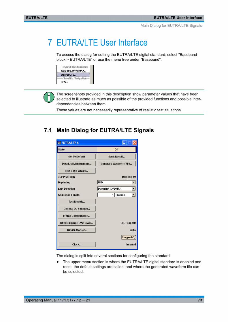
EUTRA/LTE User InterfaceEUTRA/LTE
73Operating Manual 1171.5177.12 ─ 21
7 EUTRA/LTE User InterfaceTo access the dialog for setting the EUTRA/LTE digital standard, select "Basebandblock > EUTRA/LTE" or use the menu tree under "Baseband".
The screenshots provided in this description show parameter values that have beenselected to illustrate as much as possible of the provided functions and possible inter-dependencies between them.These values are not necessarily representative of realistic test situations.
7.1 Main Dialog for EUTRA/LTE Signals
The dialog is split into several sections for configuring the standard:● The upper menu section is where the EUTRA/LTE digital standard is enabled and
reset, the default settings are called, and where the generated waveform file canbe selected.
Main Dialog for EUTRA/LTE Signals
EUTRA/LTE User InterfaceEUTRA/LTE
74Operating Manual 1171.5177.12 ─ 21
● The middle menu section is where EUTRA/LTE related settings such as the linkdirection and the sequence length can be selected.
● The buttons in the lower menu section lead to submenus to configure theEUTRA/LTE signal and setting the filter, trigger, and clock parameters.
StateActivates or deactivates the EUTRA/LTE standard.
Activating this standard disables all the other digital standards and digital modulationmodes.
In case of two-path instruments, this affects the same path.
Note: For two path instruments and configured antenna in path A for path B, enablingthe LTE signal simulation will disable all other digital standards and digital modulationmodes even in the path B.The EUTRA/LTE signal is generated according to the performed settings.
Remote command: [: SOURce<hw>]: BB:EUTRa: STATe on page 370
Set to DefaultCalls the default settings.
Parameter Values
Duplexing FDD
Link Direction Downlink (OFDMA)
Sequence Length 1 Frame
DL Channel Bandwidth 10 MHz
Physical Resource Block Bandwidth 12 * 15 kHz
Number Of Resource Blocks per Slot 50
Occupied Bandwidth /MHz 9.015
Sampling Rate /MHz 15.360
FFT Size 1024
Cell ID 0
Cyclic Prefix Normal
PHICH Duration Normal
Global MIMO Configuration 1 TxAntenna
Simulated Antenna Antenna 1
Remote command: [:SOURce<hw>]: BB: EUTRa:PRESet on page 371
Save/Recall...Calls the "Save/Recall" menu.
Main Dialog for EUTRA/LTE Signals
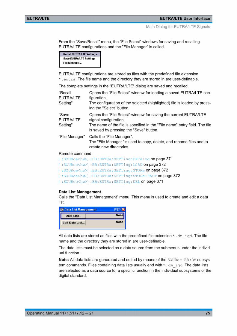
EUTRA/LTE User InterfaceEUTRA/LTE
75Operating Manual 1171.5177.12 ─ 21
From the "Save/Recall" menu, the "File Select" windows for saving and recallingEUTRA/LTE configurations and the "File Manager" is called.
EUTRA/LTE configurations are stored as files with the predefined file extension*.eutra. The file name and the directory they are stored in are user-definable.
The complete settings in the "EUTRA/LTE" dialog are saved and recalled.
"RecallEUTRA/LTESetting"
Opens the "File Select" window for loading a saved EUTRA/LTE con-figuration.The configuration of the selected (highlighted) file is loaded by press-ing the "Select" button.
"SaveEUTRA/LTESetting"
Opens the "File Select" window for saving the current EUTRA/LTEsignal configuration.The name of the file is specified in the "File name" entry field. The fileis saved by pressing the "Save" button.
"File Manager" Calls the "File Manager".The "File Manager "is used to copy, delete, and rename files and tocreate new directories.
Remote command: [:SOURce<hw>]: BB: EUTRa:SETTing: CATalog on page 371[:SOURce<hw>]: BB: EUTRa:SETTing: LOAD on page 372[:SOURce<hw>]: BB: EUTRa:SETTing: STORe on page 372[: SOURce<hw>]: BB: EUTRa:SETTing: STORe: FAST on page 372[:SOURce<hw>]: BB: EUTRa:SETTing: DEL on page 371
Data List ManagementCalls the "Data List Management" menu. This menu is used to create and edit a datalist.
All data lists are stored as files with the predefined file extension *.dm_iqd. The filename and the directory they are stored in are user-definable.
The data lists must be selected as a data source from the submenus under the individ-ual function.
Note: All data lists are generated and edited by means of the SOURce:BB:DM subsys-tem commands. Files containing data lists usually end with *.dm_iqd. The data listsare selected as a data source for a specific function in the individual subsystems of thedigital standard.
Main Dialog for EUTRA/LTE Signals
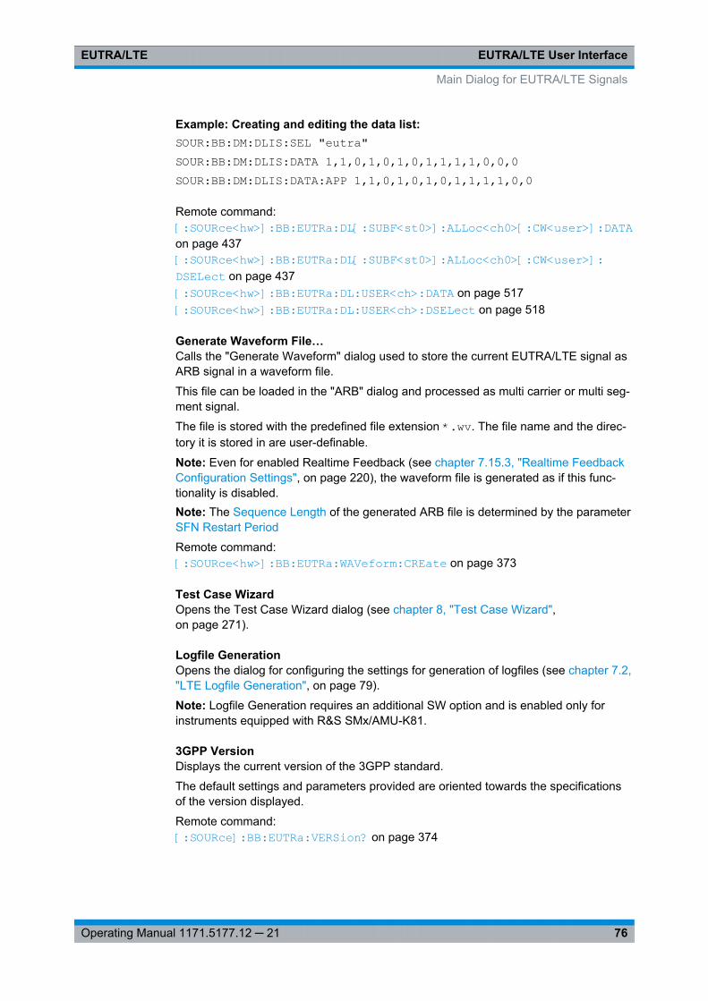
EUTRA/LTE User InterfaceEUTRA/LTE
76Operating Manual 1171.5177.12 ─ 21
Example: Creating and editing the data list:SOUR:BB:DM:DLIS:SEL "eutra"SOUR:BB:DM:DLIS:DATA 1,1,0,1,0,1,0,1,1,1,1,0,0,0SOUR:BB:DM:DLIS:DATA:APP 1,1,0,1,0,1,0,1,1,1,1,0,0
Remote command: [:SOURce<hw>]: BB: EUTRa:DL[: SUBF<st0>]: ALLoc<ch0>[: CW<user>]: DATAon page 437[:SOURce<hw>]: BB: EUTRa:DL[: SUBF<st0>]: ALLoc<ch0>[: CW<user>]: DSELect on page 437[:SOURce<hw>]: BB: EUTRa:DL: USER<ch>: DATA on page 517[:SOURce<hw>]: BB: EUTRa:DL: USER<ch>: DSELect on page 518
Generate Waveform File…Calls the "Generate Waveform" dialog used to store the current EUTRA/LTE signal asARB signal in a waveform file.
This file can be loaded in the "ARB" dialog and processed as multi carrier or multi seg-ment signal.
The file is stored with the predefined file extension *.wv. The file name and the direc-tory it is stored in are user-definable.
Note: Even for enabled Realtime Feedback (see chapter 7.15.3, "Realtime FeedbackConfiguration Settings", on page 220), the waveform file is generated as if this func-tionality is disabled.Note: The Sequence Length of the generated ARB file is determined by the parameterSFN Restart Period
Remote command: [:SOURce<hw>]: BB:EUTRa: WAVeform: CREate on page 373
Test Case WizardOpens the Test Case Wizard dialog (see chapter 8, "Test Case Wizard",on page 271).
Logfile GenerationOpens the dialog for configuring the settings for generation of logfiles (see chapter 7.2,"LTE Logfile Generation", on page 79).
Note: Logfile Generation requires an additional SW option and is enabled only forinstruments equipped with R&S SMx/AMU-K81.
3GPP VersionDisplays the current version of the 3GPP standard.
The default settings and parameters provided are oriented towards the specificationsof the version displayed.
Remote command: [:SOURce]: BB:EUTRa: VERSion? on page 374
Main Dialog for EUTRA/LTE Signals
EUTRA/LTE User InterfaceEUTRA/LTE
77Operating Manual 1171.5177.12 ─ 21
DuplexingSelects the duplexing mode. The duplexing mode determines how the uplink anddownlink signals are separated.
"TDD" In TDD mode, the same frequency is used for both directions oftransmission (uplink and downlink). With one baseband, either onlydownlink or only uplink can be generated.
"FDD" In FDD mode, different frequencies are used for downlink and uplinkdirections.
Remote command: [:SOURce<hw>]: BB: EUTRa:DUPLexing on page 370
Link DirectionSelects the transmission direction.
"Downlink(OFDMA)"
The transmission direction selected is base station to user equip-ment. The signal corresponds to that of a base station. For the down-link, the physical layer mode is always set to OFDMA.
"Uplink (SC-FDMA)"
The transmission direction selected is user equipment to base sta-tion. The signal corresponds to that of a user equipment. For theuplink, the physical layer mode is always set to SC-FDMA.
Remote command: [:SOURce<hw>]: BB: EUTRa:LINK on page 370
Sequence LengthSets the sequence length of the signal in number of frames. One frame corresponds to10 ms. The signal is calculated in advance and output in the arbitrary waveform gener-ator. The maximum number of frames is calculated as follows:
Max. No. of Frames = Arbitrary waveform memory size/(sampling rate x 10 ms).
If the Realtime Feedback functionality is enabled, the signal of UE1 does not dependon the sequence length, since this signal is not calculated in advance. The configura-tion of the sequence length is then only required, if also the signal of UE2, UE3 or UE4is used.
Remote command: [:SOURce<hw>]: BB:EUTRa: SLENgth on page 373
Test Setups/ModelsCalls dialog for selecting one of the test models defined in the 3GPP specification TS36.141 and the self-defined test setups.
The dialog is described in chapter 7.3, "Test Setups/Models", on page 93.
Remote command: n.a.
General DL Settings…/ General UL Settings…The name of the button depends on the chosen link direction.
Calls the "General DL Settings / General UL Settings" dialog for configuring theEUTRA/LTE system.
Main Dialog for EUTRA/LTE Signals
EUTRA/LTE User InterfaceEUTRA/LTE
78Operating Manual 1171.5177.12 ─ 21
The dialogs are described respectively in chapter 7.4, "General DL Settings / GeneralTDD DL Settings", on page 94 and chapter 7.13, "General UL Settings",on page 193.
Remote command: n.a.
Frame Configuration…Calls the "Frame Configuration" dialog for configuring the allocation of the resourceblocks to the different users, as well as the configuration of the users.
The dialog depends on the chosen link direction. The menu is described in chapter 7.5,"DL Frame Configuration Settings", on page 133 and chapter 7.14, "UL Frame Config-uration Settings", on page 206 respectively.
Remote command: n.a.
Filtering/Clipping/Power...Calls the menu for setting baseband filtering, clipping and the general power settings.The current filter and the clipping state are displayed next to the button.
The menu is described in chapter 7.20, "Filter/Clipping/Power Settings", on page 251.
Remote command: n.a.
Trigger/Marker(R&S SMx and R&S AMU instruments only)
Calls the dialog for selecting the trigger mode and trigger source, for configuring themarker signals, and for setting the time delay of an external trigger signal. This dialogis described in chapter 7.21, "Trigger/Marker/Clock Settings", on page 259.
The currently selected trigger mode and trigger source are displayed next to the but-ton.
Remote command: n.a.
Execute TriggerExecutes trigger manually. A manual trigger can be executed only when an internaltrigger source and a trigger mode other than "Auto" have been selected.
Remote command: [: SOURce<hw>]: BB:EUTRa: TRIGger: EXECute on page 391
ArmStops signal generation. This button appears only with "Running" signal generation inthe "Armed_Auto" and "Armed_Retrigger" trigger modes.
Signal generation can be restarted by a new trigger (internally with "Execute Trigger"or externally).
Remote command: [:SOURce<hw>]: BB: EUTRa:TRIGger: ARM:EXECute on page 390
Main Dialog for EUTRA/LTE Signals
EUTRA/LTE User InterfaceEUTRA/LTE
79Operating Manual 1171.5177.12 ─ 21
Clock(R&S SMx and R&S AMU instruments only)
Calls the menu for selecting the clock source and for setting a delay.
This menu is described in chapter 7.21.5, "Clock Settings", on page 268.
Remote command: n.a.
7.2 LTE Logfile Generation
Logfile generation functionality requires the additional option R&S SMx/AMU-K81.
This functionality enables you to generate logfiles for exchanging intermediate resultsof different logging points in the signal processing chain. Analysing the content of thelogfiles may help to verify the signal processing chain in both the DL and UL direction.The intermediate results provide a basis for enhanced debugging. To verify the FECimplementation of the DUT for instance, the coded bitstream from the instrument canbe loaded into a Rx software module for offline analysis in a simulation environment, orit can be compared to the bitstreams from a Tx software module. Due to the full remotecontrol of this functionality, optimization of the design flow with process automatizationcan be achived, too.
7.2.1 Signal Processing Chains and Logging Points
Logfile generation can be enabled after a completed processing step of the selectedchannel, at the so called logging point. Logging points (PTxx) are available after eachcompleted processing stage up to the "Precoding", as shown on the figures bellow.
The results of the "Resource Element Mapping/OFDM Mapper" are not logged!
For detailed information about the signal processing of all channels, refer to the corre-sponding 3GPP specification.
LTE Logfile Generation

EUTRA/LTE User InterfaceEUTRA/LTE
80Operating Manual 1171.5177.12 ─ 21
Signal Processing in Downlink
Fig. 7-1: Transport channel processing for DL-SCH (according to 3GPP TS 36.212)
Fig. 7-2: Overview of physical channel processing (according to 3GPP TS 36.211)
The table 7-1 gives an overview of the logging point available for the DL channels.
Table 7-1: Available logging points per DL channel
Point/Channel
PT00
TB
PT01
TBCRC
PT02
CBCRC
PT03
CC
PT04
RM
PT05
CBCON
PT06
SCR
PT07
MOD
PT08
MAP
PT09
PREC
PDSCH X X X X X X X X X X
PBCH 1) X X X X X X X X
PCFICH 1) X X X X X
PHICH 1) X X 2) X 2) X 2)
LTE Logfile Generation
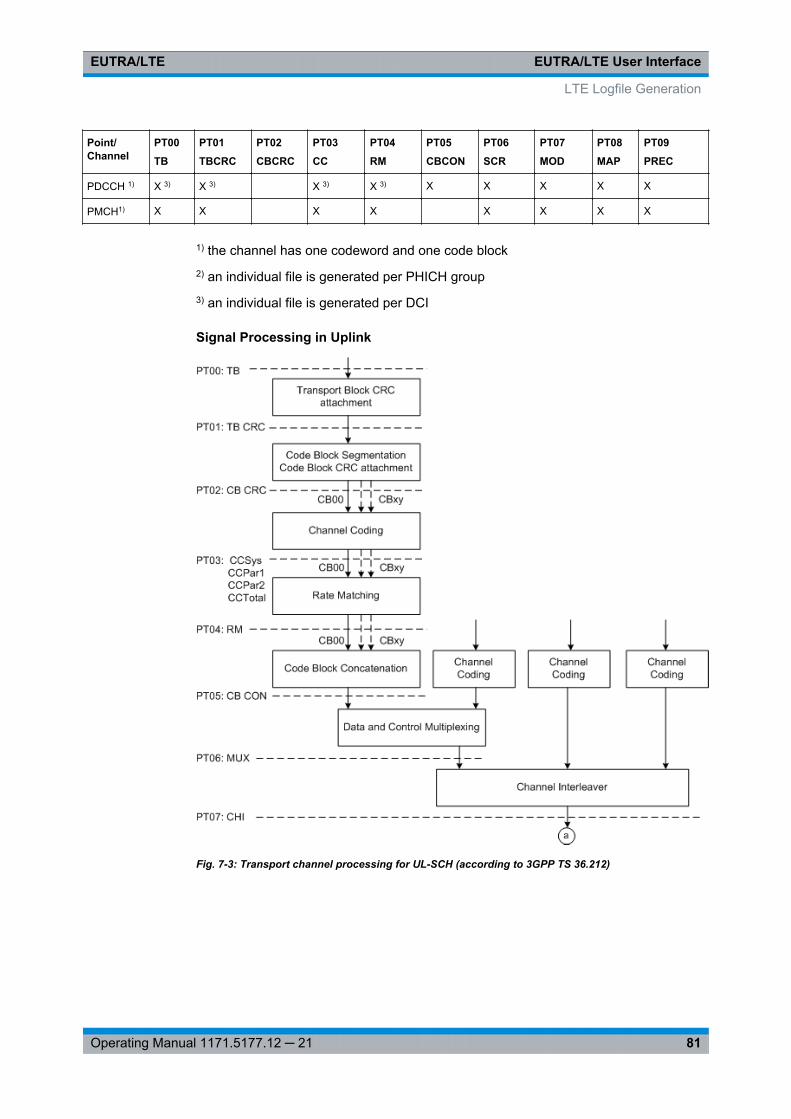
EUTRA/LTE User InterfaceEUTRA/LTE
81Operating Manual 1171.5177.12 ─ 21
Point/Channel
PT00
TB
PT01
TBCRC
PT02
CBCRC
PT03
CC
PT04
RM
PT05
CBCON
PT06
SCR
PT07
MOD
PT08
MAP
PT09
PREC
PDCCH 1) X 3) X 3) X 3) X 3) X X X X X
PMCH1) X X X X X X X X
1) the channel has one codeword and one code block2) an individual file is generated per PHICH group3) an individual file is generated per DCI
Signal Processing in Uplink
Fig. 7-3: Transport channel processing for UL-SCH (according to 3GPP TS 36.212)
LTE Logfile Generation
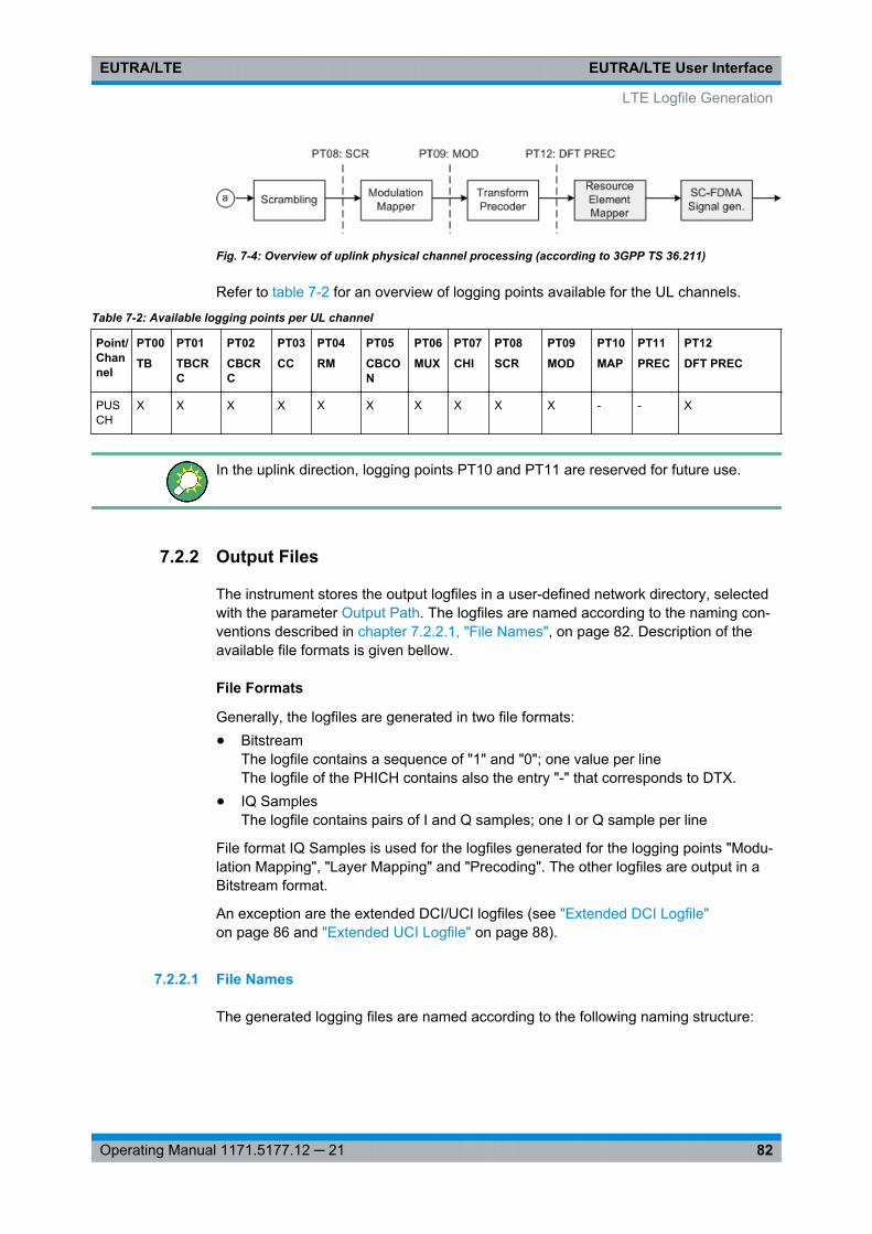
EUTRA/LTE User InterfaceEUTRA/LTE
82Operating Manual 1171.5177.12 ─ 21
Fig. 7-4: Overview of uplink physical channel processing (according to 3GPP TS 36.211)
Refer to table 7-2 for an overview of logging points available for the UL channels.
Table 7-2: Available logging points per UL channel
Point/Channel
PT00
TB
PT01
TBCRC
PT02
CBCRC
PT03
CC
PT04
RM
PT05
CBCON
PT06
MUX
PT07
CHI
PT08
SCR
PT09
MOD
PT10
MAP
PT11
PREC
PT12
DFT PREC
PUSCH
X X X X X X X X X X - - X
In the uplink direction, logging points PT10 and PT11 are reserved for future use.
7.2.2 Output Files
The instrument stores the output logfiles in a user-defined network directory, selectedwith the parameter Output Path. The logfiles are named according to the naming con-ventions described in chapter 7.2.2.1, "File Names", on page 82. Description of theavailable file formats is given bellow.
File Formats
Generally, the logfiles are generated in two file formats:● Bitstream
The logfile contains a sequence of "1" and "0"; one value per lineThe logfile of the PHICH contains also the entry "-" that corresponds to DTX.
● IQ SamplesThe logfile contains pairs of I and Q samples; one I or Q sample per line
File format IQ Samples is used for the logfiles generated for the logging points "Modu-lation Mapping", "Layer Mapping" and "Precoding". The other logfiles are output in aBitstream format.
An exception are the extended DCI/UCI logfiles (see "Extended DCI Logfile"on page 86 and "Extended UCI Logfile" on page 88).
7.2.2.1 File Names
The generated logging files are named according to the following naming structure:
LTE Logfile Generation
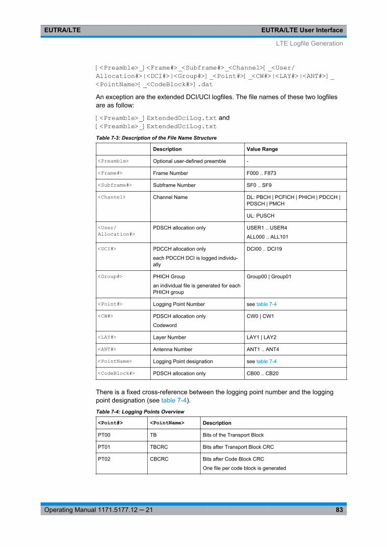
EUTRA/LTE User InterfaceEUTRA/LTE
83Operating Manual 1171.5177.12 ─ 21
[<Preamble>_]<Frame#>_<Subframe#>_<Channel>[_<User/Allocation#>|<DCI#>|<Group#>]_<Point#>[_<CW#>|<LAY#>|<ANT#>]_<PointName>[_<CodeBlock#>].datAn exception are the extended DCI/UCI logfiles. The file names of these two logfilesare as follow:
[<Preamble>_]ExtendedDciLog.txt and[<Preamble>_]ExtendedUciLog.txtTable 7-3: Description of the File Name Structure
Description Value Range
<Preamble> Optional user-defined preamble -
<Frame#> Frame Number F000 .. F873
<Subframe#> Subframe Number SF0 .. SF9
<Channel> Channel Name DL: PBCH | PCFICH | PHICH | PDCCH |PDSCH | PMCH
UL: PUSCH
<User/Allocation#>
PDSCH allocation only USER1 .. USER4
ALL000 .. ALL101
<DCI#> PDCCH allocation only
each PDCCH DCI is logged individu-ally
DCI00 .. DCI19
<Group#> PHICH Group
an individual file is generated for eachPHICH group
Group00 | Group01
<Point#> Logging Point Number see table 7-4
<CW#> PDSCH allocation only
Codeword
CW0 | CW1
<LAY#> Layer Number LAY1 | LAY2
<ANT#> Antenna Number ANT1 .. ANT4
<PointName> Logging Point designation see table 7-4
<CodeBlock#> PDSCH allocation only CB00 .. CB20
There is a fixed cross-reference between the logging point number and the loggingpoint designation (see table 7-4).
Table 7-4: Logging Points Overview
<Point#> <PointName> Description
PT00 TB Bits of the Transport Block
PT01 TBCRC Bits after Transport Block CRC
PT02 CBCRC Bits after Code Block CRC
One file per code block is generated
LTE Logfile Generation
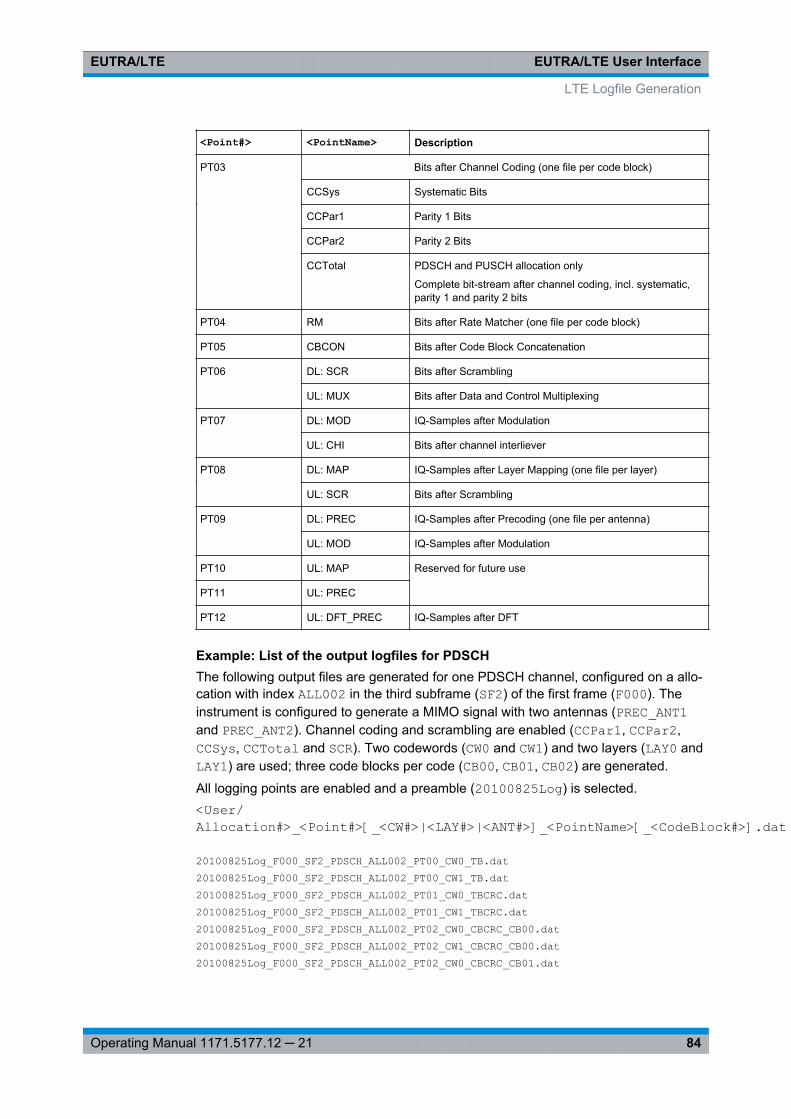
EUTRA/LTE User InterfaceEUTRA/LTE
84Operating Manual 1171.5177.12 ─ 21
<Point#> <PointName> Description
PT03 Bits after Channel Coding (one file per code block)
CCSys Systematic Bits
CCPar1 Parity 1 Bits
CCPar2 Parity 2 Bits
CCTotal PDSCH and PUSCH allocation only
Complete bit-stream after channel coding, incl. systematic,parity 1 and parity 2 bits
PT04 RM Bits after Rate Matcher (one file per code block)
PT05 CBCON Bits after Code Block Concatenation
PT06 DL: SCR Bits after Scrambling
UL: MUX Bits after Data and Control Multiplexing
PT07 DL: MOD IQ-Samples after Modulation
UL: CHI Bits after channel interliever
PT08 DL: MAP IQ-Samples after Layer Mapping (one file per layer)
UL: SCR Bits after Scrambling
PT09 DL: PREC IQ-Samples after Precoding (one file per antenna)
UL: MOD IQ-Samples after Modulation
PT10 UL: MAP Reserved for future use
PT11 UL: PREC
PT12 UL: DFT_PREC IQ-Samples after DFT
Example: List of the output logfiles for PDSCHThe following output files are generated for one PDSCH channel, configured on a allo-cation with index ALL002 in the third subframe (SF2) of the first frame (F000). Theinstrument is configured to generate a MIMO signal with two antennas (PREC_ANT1and PREC_ANT2). Channel coding and scrambling are enabled (CCPar1, CCPar2,CCSys, CCTotal and SCR). Two codewords (CW0 and CW1) and two layers (LAY0 andLAY1) are used; three code blocks per code (CB00, CB01, CB02) are generated.
All logging points are enabled and a preamble (20100825Log) is selected.<User/Allocation#>_<Point#>[_<CW#>|<LAY#>|<ANT#>]_<PointName>[_<CodeBlock#>].dat
20100825Log_F000_SF2_PDSCH_ALL002_PT00_CW0_TB.dat20100825Log_F000_SF2_PDSCH_ALL002_PT00_CW1_TB.dat20100825Log_F000_SF2_PDSCH_ALL002_PT01_CW0_TBCRC.dat20100825Log_F000_SF2_PDSCH_ALL002_PT01_CW1_TBCRC.dat20100825Log_F000_SF2_PDSCH_ALL002_PT02_CW0_CBCRC_CB00.dat20100825Log_F000_SF2_PDSCH_ALL002_PT02_CW1_CBCRC_CB00.dat20100825Log_F000_SF2_PDSCH_ALL002_PT02_CW0_CBCRC_CB01.dat
LTE Logfile Generation
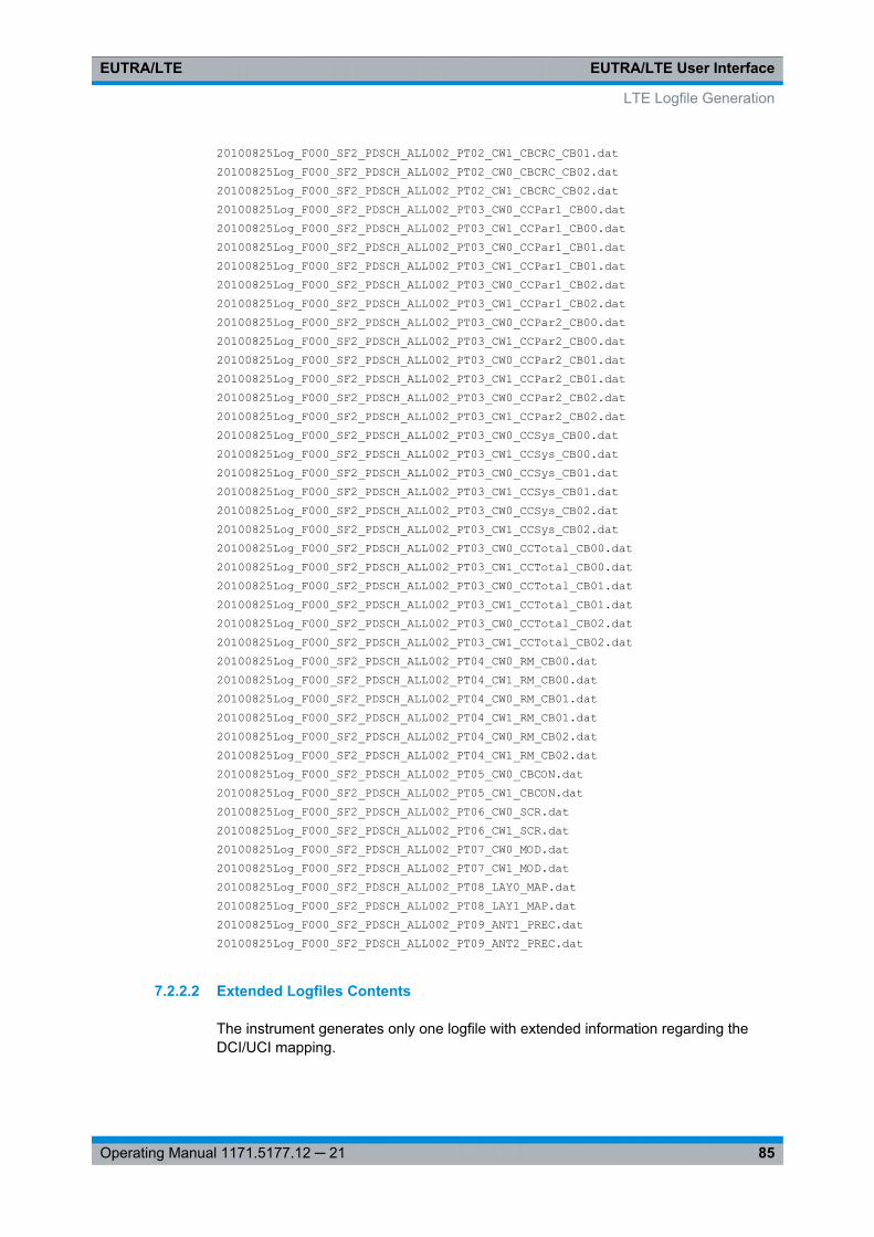
EUTRA/LTE User InterfaceEUTRA/LTE
85Operating Manual 1171.5177.12 ─ 21
20100825Log_F000_SF2_PDSCH_ALL002_PT02_CW1_CBCRC_CB01.dat20100825Log_F000_SF2_PDSCH_ALL002_PT02_CW0_CBCRC_CB02.dat20100825Log_F000_SF2_PDSCH_ALL002_PT02_CW1_CBCRC_CB02.dat20100825Log_F000_SF2_PDSCH_ALL002_PT03_CW0_CCPar1_CB00.dat20100825Log_F000_SF2_PDSCH_ALL002_PT03_CW1_CCPar1_CB00.dat20100825Log_F000_SF2_PDSCH_ALL002_PT03_CW0_CCPar1_CB01.dat20100825Log_F000_SF2_PDSCH_ALL002_PT03_CW1_CCPar1_CB01.dat20100825Log_F000_SF2_PDSCH_ALL002_PT03_CW0_CCPar1_CB02.dat20100825Log_F000_SF2_PDSCH_ALL002_PT03_CW1_CCPar1_CB02.dat20100825Log_F000_SF2_PDSCH_ALL002_PT03_CW0_CCPar2_CB00.dat20100825Log_F000_SF2_PDSCH_ALL002_PT03_CW1_CCPar2_CB00.dat20100825Log_F000_SF2_PDSCH_ALL002_PT03_CW0_CCPar2_CB01.dat20100825Log_F000_SF2_PDSCH_ALL002_PT03_CW1_CCPar2_CB01.dat20100825Log_F000_SF2_PDSCH_ALL002_PT03_CW0_CCPar2_CB02.dat20100825Log_F000_SF2_PDSCH_ALL002_PT03_CW1_CCPar2_CB02.dat20100825Log_F000_SF2_PDSCH_ALL002_PT03_CW0_CCSys_CB00.dat20100825Log_F000_SF2_PDSCH_ALL002_PT03_CW1_CCSys_CB00.dat20100825Log_F000_SF2_PDSCH_ALL002_PT03_CW0_CCSys_CB01.dat20100825Log_F000_SF2_PDSCH_ALL002_PT03_CW1_CCSys_CB01.dat20100825Log_F000_SF2_PDSCH_ALL002_PT03_CW0_CCSys_CB02.dat20100825Log_F000_SF2_PDSCH_ALL002_PT03_CW1_CCSys_CB02.dat20100825Log_F000_SF2_PDSCH_ALL002_PT03_CW0_CCTotal_CB00.dat20100825Log_F000_SF2_PDSCH_ALL002_PT03_CW1_CCTotal_CB00.dat20100825Log_F000_SF2_PDSCH_ALL002_PT03_CW0_CCTotal_CB01.dat20100825Log_F000_SF2_PDSCH_ALL002_PT03_CW1_CCTotal_CB01.dat20100825Log_F000_SF2_PDSCH_ALL002_PT03_CW0_CCTotal_CB02.dat20100825Log_F000_SF2_PDSCH_ALL002_PT03_CW1_CCTotal_CB02.dat20100825Log_F000_SF2_PDSCH_ALL002_PT04_CW0_RM_CB00.dat20100825Log_F000_SF2_PDSCH_ALL002_PT04_CW1_RM_CB00.dat20100825Log_F000_SF2_PDSCH_ALL002_PT04_CW0_RM_CB01.dat20100825Log_F000_SF2_PDSCH_ALL002_PT04_CW1_RM_CB01.dat20100825Log_F000_SF2_PDSCH_ALL002_PT04_CW0_RM_CB02.dat20100825Log_F000_SF2_PDSCH_ALL002_PT04_CW1_RM_CB02.dat20100825Log_F000_SF2_PDSCH_ALL002_PT05_CW0_CBCON.dat20100825Log_F000_SF2_PDSCH_ALL002_PT05_CW1_CBCON.dat20100825Log_F000_SF2_PDSCH_ALL002_PT06_CW0_SCR.dat20100825Log_F000_SF2_PDSCH_ALL002_PT06_CW1_SCR.dat20100825Log_F000_SF2_PDSCH_ALL002_PT07_CW0_MOD.dat20100825Log_F000_SF2_PDSCH_ALL002_PT07_CW1_MOD.dat20100825Log_F000_SF2_PDSCH_ALL002_PT08_LAY0_MAP.dat20100825Log_F000_SF2_PDSCH_ALL002_PT08_LAY1_MAP.dat20100825Log_F000_SF2_PDSCH_ALL002_PT09_ANT1_PREC.dat20100825Log_F000_SF2_PDSCH_ALL002_PT09_ANT2_PREC.dat
7.2.2.2 Extended Logfiles Contents
The instrument generates only one logfile with extended information regarding theDCI/UCI mapping.
LTE Logfile Generation
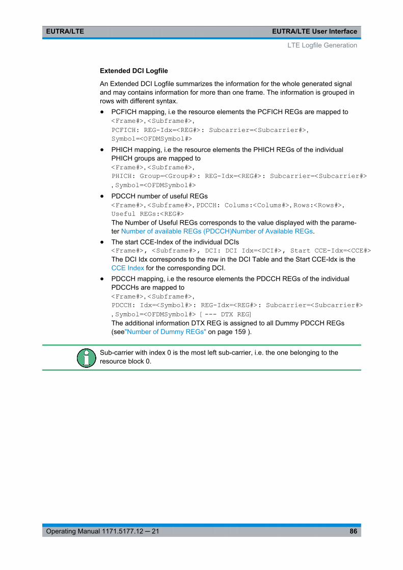
EUTRA/LTE User InterfaceEUTRA/LTE
86Operating Manual 1171.5177.12 ─ 21
Extended DCI Logfile
An Extended DCI Logfile summarizes the information for the whole generated signaland may contains information for more than one frame. The information is grouped inrows with different syntax.● PCFICH mapping, i.e the resource elements the PCFICH REGs are mapped to
<Frame#>, <Subframe#>,PCFICH: REG-Idx=<REG#>: Subcarrier=<Subcarrier#>,Symbol=<OFDMSymbol#>
● PHICH mapping, i.e the resource elements the PHICH REGs of the individualPHICH groups are mapped to<Frame#>, <Subframe#>,PHICH: Group=<Group#>: REG-Idx=<REG#>: Subcarrier=<Subcarrier#>, Symbol=<OFDMSymbol#>
● PDCCH number of useful REGs<Frame#>, <Subframe#>, PDCCH: Colums:<Colums#>, Rows:<Rows#>,Useful REGs:<REG#>The Number of Useful REGs corresponds to the value displayed with the parame-ter Number of available REGs (PDCCH)Number of Available REGs.
● The start CCE-Index of the individual DCIs<Frame#>, <Subframe#>, DCI: DCI Idx=<DCI#>, Start CCE-Idx=<CCE#>The DCI Idx corresponds to the row in the DCI Table and the Start CCE-Idx is theCCE Index for the corresponding DCI.
● PDCCH mapping, i.e the resource elements the PDCCH REGs of the individualPDCCHs are mapped to<Frame#>, <Subframe#>,PDCCH: Idx=<Symbol#>: REG-Idx=<REG#>: Subcarrier=<Subcarrier#>, Symbol=<OFDMSymbol#> [--- DTX REG]The additional information DTX REG is assigned to all Dummy PDCCH REGs(see"Number of Dummy REGs" on page 159 ).
Sub-carrier with index 0 is the most left sub-carrier, i.e. the one belonging to theresource block 0.
LTE Logfile Generation
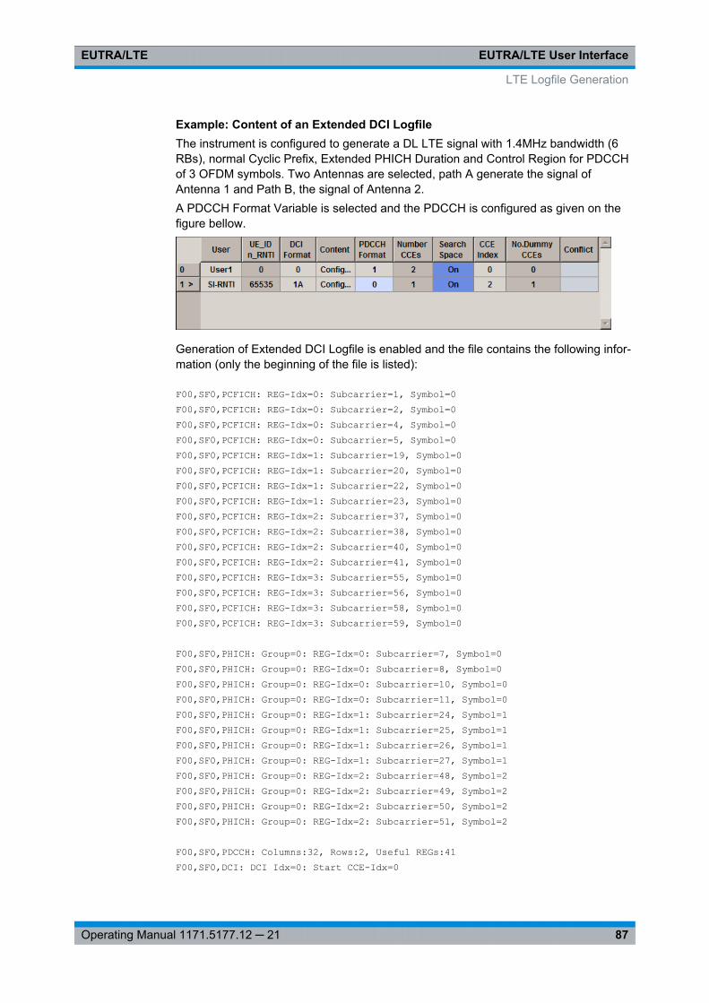
EUTRA/LTE User InterfaceEUTRA/LTE
87Operating Manual 1171.5177.12 ─ 21
Example: Content of an Extended DCI LogfileThe instrument is configured to generate a DL LTE signal with 1.4MHz bandwidth (6RBs), normal Cyclic Prefix, Extended PHICH Duration and Control Region for PDCCHof 3 OFDM symbols. Two Antennas are selected, path A generate the signal ofAntenna 1 and Path B, the signal of Antenna 2.A PDCCH Format Variable is selected and the PDCCH is configured as given on thefigure bellow.
Generation of Extended DCI Logfile is enabled and the file contains the following infor-mation (only the beginning of the file is listed):
F00,SF0,PCFICH: REG-Idx=0: Subcarrier=1, Symbol=0F00,SF0,PCFICH: REG-Idx=0: Subcarrier=2, Symbol=0F00,SF0,PCFICH: REG-Idx=0: Subcarrier=4, Symbol=0F00,SF0,PCFICH: REG-Idx=0: Subcarrier=5, Symbol=0F00,SF0,PCFICH: REG-Idx=1: Subcarrier=19, Symbol=0F00,SF0,PCFICH: REG-Idx=1: Subcarrier=20, Symbol=0F00,SF0,PCFICH: REG-Idx=1: Subcarrier=22, Symbol=0F00,SF0,PCFICH: REG-Idx=1: Subcarrier=23, Symbol=0F00,SF0,PCFICH: REG-Idx=2: Subcarrier=37, Symbol=0F00,SF0,PCFICH: REG-Idx=2: Subcarrier=38, Symbol=0F00,SF0,PCFICH: REG-Idx=2: Subcarrier=40, Symbol=0F00,SF0,PCFICH: REG-Idx=2: Subcarrier=41, Symbol=0F00,SF0,PCFICH: REG-Idx=3: Subcarrier=55, Symbol=0F00,SF0,PCFICH: REG-Idx=3: Subcarrier=56, Symbol=0F00,SF0,PCFICH: REG-Idx=3: Subcarrier=58, Symbol=0F00,SF0,PCFICH: REG-Idx=3: Subcarrier=59, Symbol=0
F00,SF0,PHICH: Group=0: REG-Idx=0: Subcarrier=7, Symbol=0F00,SF0,PHICH: Group=0: REG-Idx=0: Subcarrier=8, Symbol=0F00,SF0,PHICH: Group=0: REG-Idx=0: Subcarrier=10, Symbol=0F00,SF0,PHICH: Group=0: REG-Idx=0: Subcarrier=11, Symbol=0F00,SF0,PHICH: Group=0: REG-Idx=1: Subcarrier=24, Symbol=1F00,SF0,PHICH: Group=0: REG-Idx=1: Subcarrier=25, Symbol=1F00,SF0,PHICH: Group=0: REG-Idx=1: Subcarrier=26, Symbol=1F00,SF0,PHICH: Group=0: REG-Idx=1: Subcarrier=27, Symbol=1F00,SF0,PHICH: Group=0: REG-Idx=2: Subcarrier=48, Symbol=2F00,SF0,PHICH: Group=0: REG-Idx=2: Subcarrier=49, Symbol=2F00,SF0,PHICH: Group=0: REG-Idx=2: Subcarrier=50, Symbol=2F00,SF0,PHICH: Group=0: REG-Idx=2: Subcarrier=51, Symbol=2
F00,SF0,PDCCH: Columns:32, Rows:2, Useful REGs:41F00,SF0,DCI: DCI Idx=0: Start CCE-Idx=0
LTE Logfile Generation
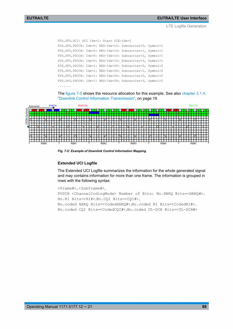
EUTRA/LTE User InterfaceEUTRA/LTE
88Operating Manual 1171.5177.12 ─ 21
F00,SF0,DCI: DCI Idx=1: Start CCE-Idx=2F00,SF0,PDCCH: Idx=0: REG-Idx=10: Subcarrier=0, Symbol=1F00,SF0,PDCCH: Idx=0: REG-Idx=10: Subcarrier=1, Symbol=1F00,SF0,PDCCH: Idx=0: REG-Idx=10: Subcarrier=2, Symbol=1F00,SF0,PDCCH: Idx=0: REG-Idx=10: Subcarrier=3, Symbol=1F00,SF0,PDCCH: Idx=1: REG-Idx=26: Subcarrier=0, Symbol=2F00,SF0,PDCCH: Idx=1: REG-Idx=26: Subcarrier=1, Symbol=2F00,SF0,PDCCH: Idx=1: REG-Idx=26: Subcarrier=2, Symbol=2F00,SF0,PDCCH: Idx=1: REG-Idx=26: Subcarrier=3, Symbol=2.......
The figure 7-5 shows the resource allocation for this example. See also chapter 3.1.4,"Downlink Control Information Transmission", on page 19.
Fig. 7-5: Example of Downlink Control Information Mapping
Extended UCI Logfile
The Extended UCI Logfile summarizes the information for the whole generated signaland may contains information for more than one frame. The information is grouped inrows with the following syntax:
<Frame#>, <Subframe#>,PUSCH <ChannelCodingMode> Number of Bits: No.HARQ Bits=<HARQ#>,No.RI Bits=<RI#>,No.CQI Bits=<CQI#>,No.coded HARQ Bits=<CodedHARQ#>,No.coded RI Bits=<CodedRI#>,No.coded CQI Bits=<CodedCQI#>,No.coded UL-SCH Bits=<UL-SCH#>
LTE Logfile Generation
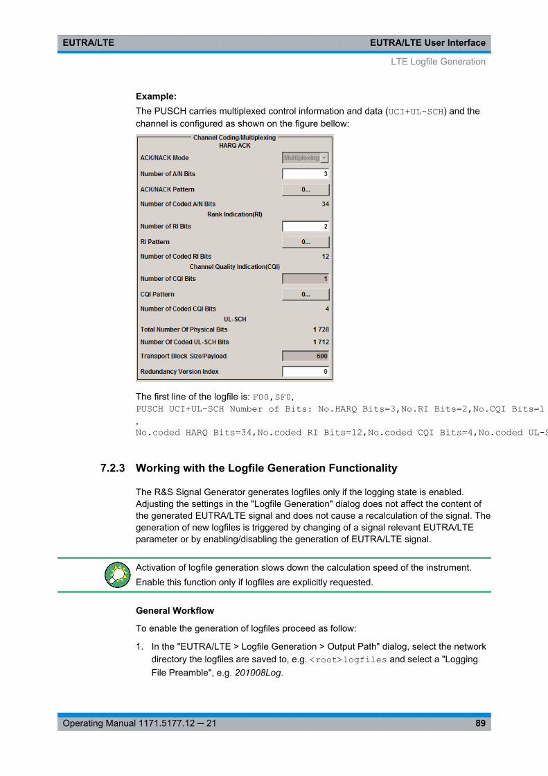
EUTRA/LTE User InterfaceEUTRA/LTE
89Operating Manual 1171.5177.12 ─ 21
Example: The PUSCH carries multiplexed control information and data (UCI+UL-SCH) and thechannel is configured as shown on the figure bellow:
The first line of the logfile is: F00,SF0,PUSCH UCI+UL-SCH Number of Bits: No.HARQ Bits=3,No.RI Bits=2,No.CQI Bits=1,No.coded HARQ Bits=34,No.coded RI Bits=12,No.coded CQI Bits=4,No.coded UL-SCH Bits=1712
7.2.3 Working with the Logfile Generation Functionality
The R&S Signal Generator generates logfiles only if the logging state is enabled.Adjusting the settings in the "Logfile Generation" dialog does not affect the content ofthe generated EUTRA/LTE signal and does not cause a recalculation of the signal. Thegeneration of new logfiles is triggered by changing of a signal relevant EUTRA/LTEparameter or by enabling/disabling the generation of EUTRA/LTE signal.
Activation of logfile generation slows down the calculation speed of the instrument.Enable this function only if logfiles are explicitly requested.
General Workflow
To enable the generation of logfiles proceed as follow:
1. In the "EUTRA/LTE > Logfile Generation > Output Path" dialog, select the networkdirectory the logfiles are saved to, e.g. <root>logfiles and select a "LoggingFile Preamble", e.g. 201008Log.
LTE Logfile Generation
EUTRA/LTE User InterfaceEUTRA/LTE
90Operating Manual 1171.5177.12 ─ 21
Note: The network directory should be empty. Existing logfiles are overwritten.It is recommended to use different preambles to assure that previous logfiles arenot lost.
2. If required, enable "Extended DCI/UCI Logging".
3. Select the processing chain points for that logfiles are to be generated, e.g. "Point3: Channel Coding".
Tip: Not all of the available logging point are relevant for all channels. The pro-cessing of the PBCH for instance does not include the step "Code block segmenta-tion / CRC", i.e. even if the Logging Point "Point 2: Code block segmentation /CRC" is enabled, no logfile is generated (see table 7-1).No logfiles are generated also in case that the corresponding processing step isdisabled in the EUTRA/LTE dialog. For example, if channel coding and/or scram-bling are disabled for some channel, no logfiles for the Point 3 and/or Point 6/Point8 are available for this channel as long as these processing steps are not enabled.
4. Set the "Logging State" to On to enable logfile generation.
5. Adjust the EUTRA/LTE Settings as required and enable signal generation.
7.2.4 Logfile Generation Settings
► To access this dialog, select "EUTRA/LTE > General > Logfile Generation".
The dialog is divided into three main areas. The first one is where the logfile gener-ation is enabled and the settings of the output file are configured. In the secondone, the channels are selceted for which logfiles are to be generated. The last oneenables the selection of the logging point(s) for which logfiles will be generated.
LTE Logfile Generation
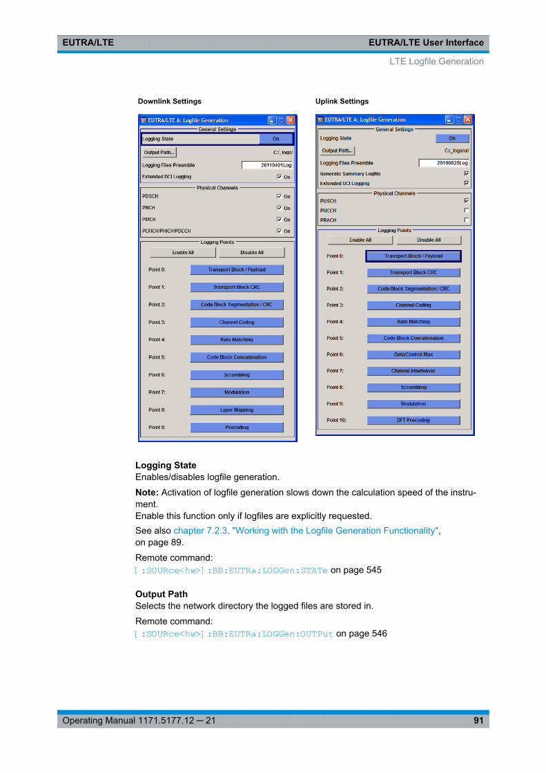
EUTRA/LTE User InterfaceEUTRA/LTE
91Operating Manual 1171.5177.12 ─ 21
Downlink Settings Uplink Settings
Logging StateEnables/disables logfile generation.
Note: Activation of logfile generation slows down the calculation speed of the instru-ment.Enable this function only if logfiles are explicitly requested.See also chapter 7.2.3, "Working with the Logfile Generation Functionality",on page 89.
Remote command: [:SOURce<hw>]: BB: EUTRa:LOGGen: STATe on page 545
Output PathSelects the network directory the logged files are stored in.
Remote command: [:SOURce<hw>]: BB:EUTRa: LOGGen: OUTPut on page 546
LTE Logfile Generation

EUTRA/LTE User InterfaceEUTRA/LTE
92Operating Manual 1171.5177.12 ─ 21
Logging Files PreambleAn optional preamble may be added to the file name. Refer to chapter 7.2.2.1, "FileNames", on page 82 for a description of the file naming convention used.
Remote command: [:SOURce<hw>]: BB: EUTRa:LOGGen: LFP on page 546
Extended DCI/UCI LoggingEnables the generation of a logfile with extended information regarding the DCI/UCImapping.
For description of the content of the generated file, see "Extended DCI Logfile"on page 86 and respectively "Extended UCI Logfile" on page 88.
Remote command: [:SOURce<hw>]: BB:EUTRa: LOGGen: DL:EDLogging on page 546[:SOURce<hw>]: BB:EUTRa:LOGGen: UL:EULogging on page 546
Physical ChannelsSelects the channel for which logfiles are generated.
Remote command: [: SOURce<hw>]: BB:EUTRa: LOGGen:DL: ENCC on page 547[: SOURce<hw>]: BB:EUTRa: LOGGen:DL: PBCH on page 547[: SOURce<hw>]: BB:EUTRa: LOGGen:DL: PDSCh on page 547[: SOURce<hw>]: BB:EUTRa: LOGGen:DL: PMCH on page 547[: SOURce<hw>]: BB:EUTRa: LOGGen:UL: PUSCh on page 547
Enable/Disable AllEnables/disables all logging points.
Remote command: [:SOURce<hw>]: BB: EUTRa:LOGGen: DL:EALL on page 546[: SOURce<hw>]: BB: EUTRa:LOGGen: DL:DALL on page 546[:SOURce<hw>]: BB: EUTRa:LOGGen: UL:EALL on page 546[:SOURce<hw>]: BB: EUTRa:LOGGen: UL:DALL on page 546
Logging PointEnables/disables one particular logging point.
Refer to chapter 7.2.1, "Signal Processing Chains and Logging Points", on page 79 fordescription on the available logging points.
Remote command: [:SOURce<hw>]: BB:EUTRa: LOGGen: DL:LOGPoint<ch0> on page 547[: SOURce<hw>]: BB:EUTRa: LOGGen: UL:LOGPoint<ch0> on page 547
LTE Logfile Generation
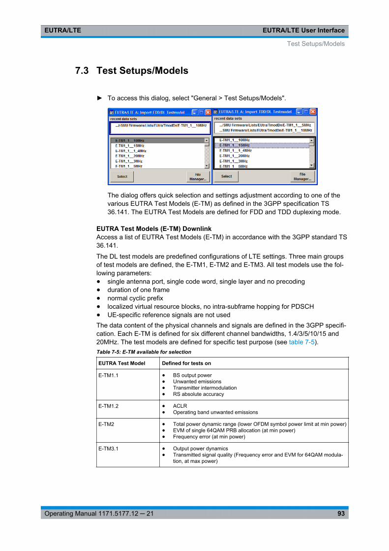
EUTRA/LTE User InterfaceEUTRA/LTE
93Operating Manual 1171.5177.12 ─ 21
7.3 Test Setups/Models
► To access this dialog, select "General > Test Setups/Models".
The dialog offers quick selection and settings adjustment according to one of thevarious EUTRA Test Models (E-TM) as defined in the 3GPP specification TS36.141. The EUTRA Test Models are defined for FDD and TDD duplexing mode.
EUTRA Test Models (E-TM) DownlinkAccess a list of EUTRA Test Models (E-TM) in accordance with the 3GPP standard TS36.141.
The DL test models are predefined configurations of LTE settings. Three main groupsof test models are defined, the E-TM1, E-TM2 and E-TM3. All test models use the fol-lowing parameters:● single antenna port, single code word, single layer and no precoding● duration of one frame● normal cyclic prefix● localized virtual resource blocks, no intra-subframe hopping for PDSCH● UE-specific reference signals are not usedThe data content of the physical channels and signals are defined in the 3GPP specifi-cation. Each E-TM is defined for six different channel bandwidths, 1.4/3/5/10/15 and20MHz. The test models are defined for specific test purpose (see table 7-5).Table 7-5: E-TM available for selection
EUTRA Test Model Defined for tests on
E-TM1.1 ● BS output power● Unwanted emissions● Transmitter intermodulation● RS absolute accuracy
E-TM1.2 ● ACLR● Operating band unwanted emissions
E-TM2 ● Total power dynamic range (lower OFDM symbol power limit at min power)● EVM of single 64QAM PRB allocation (at min power)● Frequency error (at min power)
E-TM3.1 ● Output power dynamics● Transmitted signal quality (Frequency error and EVM for 64QAM modula-
tion, at max power)
Test Setups/Models
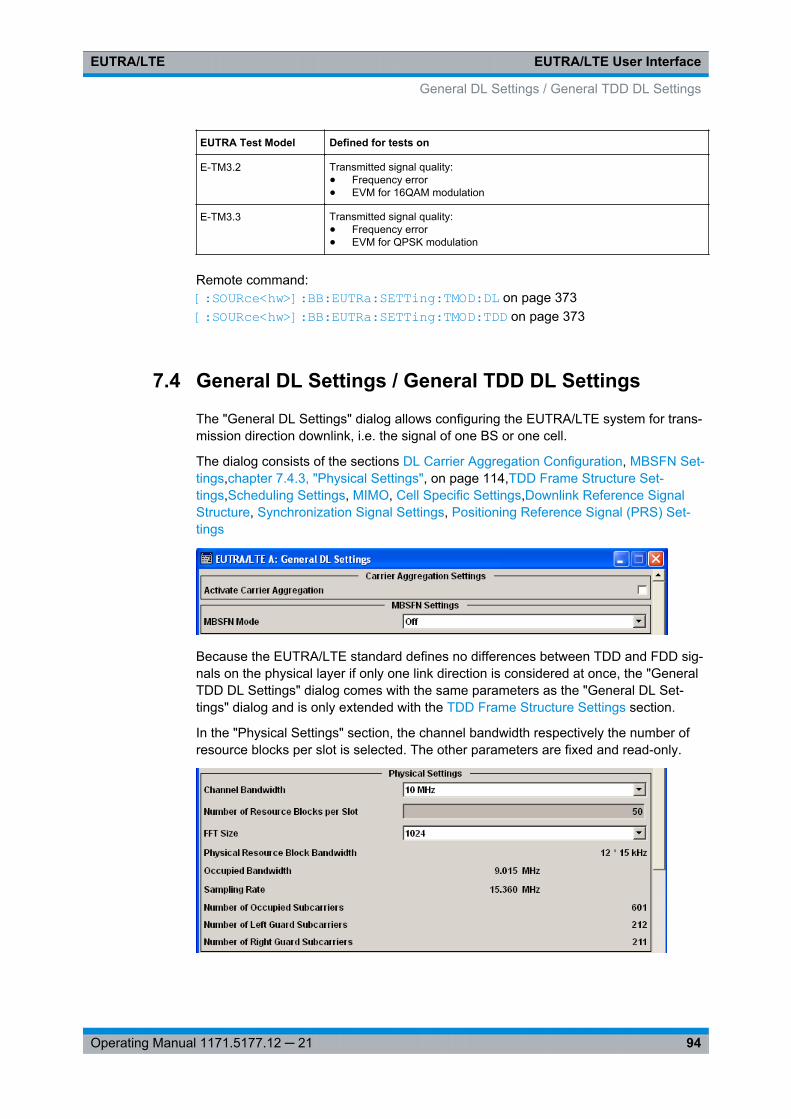
EUTRA/LTE User InterfaceEUTRA/LTE
94Operating Manual 1171.5177.12 ─ 21
EUTRA Test Model Defined for tests on
E-TM3.2 Transmitted signal quality:● Frequency error● EVM for 16QAM modulation
E-TM3.3 Transmitted signal quality:● Frequency error● EVM for QPSK modulation
Remote command: [:SOURce<hw>]: BB: EUTRa:SETTing: TMOD: DL on page 373[:SOURce<hw>]: BB: EUTRa:SETTing: TMOD: TDD on page 373
7.4 General DL Settings / General TDD DL Settings
The "General DL Settings" dialog allows configuring the EUTRA/LTE system for trans-mission direction downlink, i.e. the signal of one BS or one cell.
The dialog consists of the sections DL Carrier Aggregation Configuration, MBSFN Set-tings,chapter 7.4.3, "Physical Settings", on page 114,TDD Frame Structure Set-tings,Scheduling Settings, MIMO, Cell Specific Settings,Downlink Reference SignalStructure, Synchronization Signal Settings, Positioning Reference Signal (PRS) Set-tings
Because the EUTRA/LTE standard defines no differences between TDD and FDD sig-nals on the physical layer if only one link direction is considered at once, the "GeneralTDD DL Settings" dialog comes with the same parameters as the "General DL Set-tings" dialog and is only extended with the TDD Frame Structure Settings section.
In the "Physical Settings" section, the channel bandwidth respectively the number ofresource blocks per slot is selected. The other parameters are fixed and read-only.
General DL Settings / General TDD DL Settings
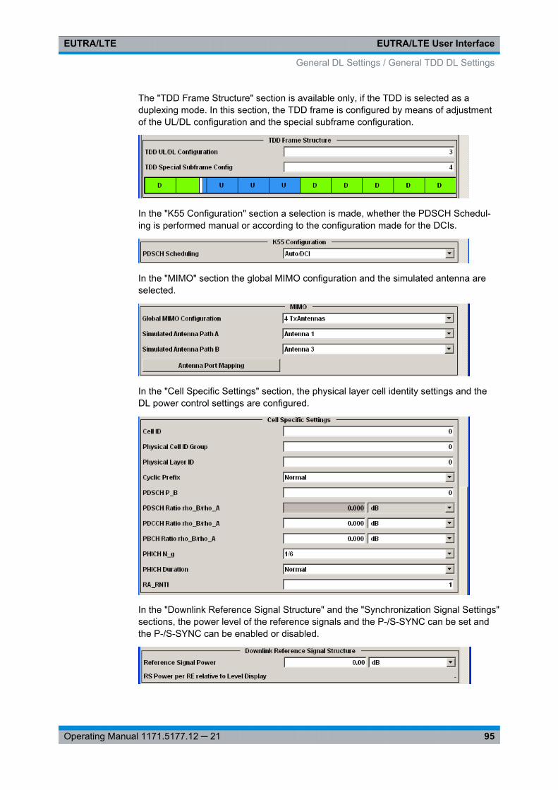
EUTRA/LTE User InterfaceEUTRA/LTE
95Operating Manual 1171.5177.12 ─ 21
The "TDD Frame Structure" section is available only, if the TDD is selected as aduplexing mode. In this section, the TDD frame is configured by means of adjustmentof the UL/DL configuration and the special subframe configuration.
In the "K55 Configuration" section a selection is made, whether the PDSCH Schedul-ing is performed manual or according to the configuration made for the DCIs.
In the "MIMO" section the global MIMO configuration and the simulated antenna areselected.
In the "Cell Specific Settings" section, the physical layer cell identity settings and theDL power control settings are configured.
In the "Downlink Reference Signal Structure" and the "Synchronization Signal Settings"sections, the power level of the reference signals and the P-/S-SYNC can be set andthe P-/S-SYNC can be enabled or disabled.
General DL Settings / General TDD DL Settings
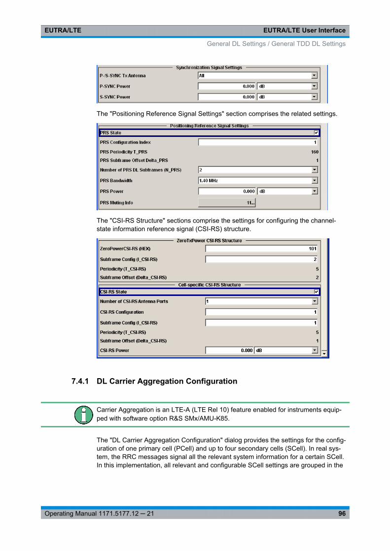
EUTRA/LTE User InterfaceEUTRA/LTE
96Operating Manual 1171.5177.12 ─ 21
The "Positioning Reference Signal Settings" section comprises the related settings.
The "CSI-RS Structure" sections comprise the settings for configuring the channel-state information reference signal (CSI-RS) structure.
7.4.1 DL Carrier Aggregation Configuration
Carrier Aggregation is an LTE-A (LTE Rel 10) feature enabled for instruments equip-ped with software option R&S SMx/AMU-K85.
The "DL Carrier Aggregation Configuration" dialog provides the settings for the config-uration of one primary cell (PCell) and up to four secondary cells (SCell). In real sys-tem, the RRC messages signal all the relevant system information for a certain SCell.In this implementation, all relevant and configurable SCell settings are grouped in the
General DL Settings / General TDD DL Settings
EUTRA/LTE User InterfaceEUTRA/LTE
97Operating Manual 1171.5177.12 ─ 21
"DL Carrier Aggregation Configuration" dialog. The remaining cell-specific settings areidentical for all component carriers.
7.4.1.1 About the Carrier Aggregation
This section lists implementation related information. For background information onthis topic, refer to chapter 3.5, "LTE-Advanced Introduction", on page 38.
In this description, the terms cell and component carrier (CC) are used interchangea-bly.
SCell settings derivation
The settings of each component carrier are calculated automatically form the config-ured PCell settings and depending on the parameters in the "DL Carrier AggregationConfiguration" dialog. The following list provides an overview of the restrictions andinterdependencies between related parameters if DL Carrier Aggregation is enabled:● Combination of FDD and TDD is not possible.● Simultaneous support of LTE and LTE-A users is provided
(see User Configuration Settings > Activate CA).● The following configurations in the PCell are not supported:
– "Channel Bandwidth = User"– "PDSCH Scheduling = Auto/DCI"
● To enable cross-carrier scheduling, the DCI formats are extended to support theCIF field. The DCIs have to be configured individually per component carrier.In this firmware version, the "PDSCH Scheduling = Auto/DCI" mode is always disa-bled and the component carriers of the SCells use the same frame configuration asthe PCell.Support of cross-carrier scheduling in "Auto/DCI" mode will be available in futureversion.
● The "Control Region for PDCCH" of all SCells is set to the same value, unless the3GPP standard specifies a specific value, e.g. in special subframes in TDD mode.The PHICH Duration of the SCells is adjusted automatically if required, i.e. if thisparameter is set to "Extended" in the PCell, the SCell are generated with extendedPHICH duration even if the "PDCCH Start" is not set properly for the SCell.However, the PHICH Duration in a SCell will be adjusted if the selected narrowchannel bandwidth in this SCell leads to unsufficient amount of PDCCH symbols.Consequently, different channel bandwidth results in different Number of availableCCEs (PDCCH).
● The parameter Number of PHICH Groups may have different values in the SCells,because it is calculated based on the parameter "N_g".
● If a SCell spans channel bandwidth with less RBs than the PCell, the instrumentignores the allocations or part of the them that is outside the channel bandwidth ofthe SCell.
General DL Settings / General TDD DL Settings
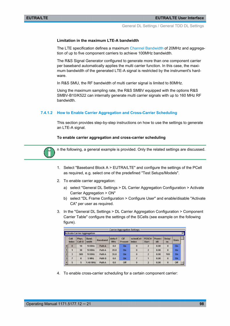
EUTRA/LTE User InterfaceEUTRA/LTE
98Operating Manual 1171.5177.12 ─ 21
Limitation in the maximum LTE-A bandwidth
The LTE specification defines a maximum Channel Bandwidth of 20MHz and aggrega-tion of up to five component carriers to achieve 100MHz bandwidth.
The R&S Signal Generator configured to generate more than one component carrierper baseband automatically applies the multi carrier function. In this case, the maxi-mum bandwidth of the generated LTE-A signal is restricted by the instrument's hard-ware.
In R&S SMU, the RF bandwidth of multi carrier signal is limited to 80MHz.
Using the maximum sampling rate, the R&S SMBV equipped with the options R&SSMBV-B10/K522 can internally generate multi carrier signals with up to 160 MHz RFbandwidth.
7.4.1.2 How to Enable Carrier Aggregation and Cross-Carrier Scheduling
This section provides step-by-step instructions on how to use the settings to generatean LTE-A signal.
To enable carrier aggregation and cross-carrier scheduling
n the following, a general example is provided. Only the related settings are discussed.
1. Select "Baseband Block A > EUTRA/LTE" and configure the settings of the PCellas required, e.g. select one of the predefined "Test Setups/Models".
2. To enable carrier aggregation:
a) select "General DL Settings > DL Carrier Aggregation Configuration > ActivateCarrier Aggregation > ON"
b) select "DL Frame Configuration > Configure User" and enable/disable "ActivateCA" per user as required.
3. In the "General DL Settings > DL Carrier Aggregation Configuration > ComponentCarrier Table" configure the settings of the SCells (see example on the followingfigure).
4. To enable cross-carrier scheduling for a certain component carrier:
General DL Settings / General TDD DL Settings
EUTRA/LTE User InterfaceEUTRA/LTE
99Operating Manual 1171.5177.12 ─ 21
a) set the "DL Carrier Aggregation Configuration > SCell# > schedCell Index = 0"In the example, the component carriers SCell#1, SCell#2 and SCell#4 can becross-scheduled over the PCell
b) enable the "DL Carrier Aggregation Configuration > SCell# > CIF Present"parameter.In this example, the component carriers SCell#1 and SCell#2 will be cross-scheduled over the PCell.
c) To enable a component carrier, set "DL Carrier Aggregation Configuration >SCell# > State > ON".
5. Enable LTE signal generation "EUTRA/LTE State > ON".
6. If required, use the Fading Simulator to configure the propagation conditions.
7. If required, adjust the RF frequency of path A to the middle frequency of the result-ing total signal bandwidth.
8. Activate the RF output.
The instrument will generate the signal in the path A as multi carrier signal, com-posed of three carrier, the PCell, the SCell#1 and SCell#2. Each of these compo-nent carrier spans "Channel Bandwidth" = 10MHz and the SCells use carrier fre-quency offset with 20MHz and 35MHz respectively.In two path instrument, the SCell#3 will be generated by the path B. The instrumentuses the internal coupled mode, i.e. path B is controlled via path A. The signal gen-erated by path B has identical parameters with the settings made for path A; thecomponent carrier specific parameters, e.g. "Channel Bandwidth" are set accord-ingly.The SCell#4 is disabled.Tip: How to configure an LTE-A signal with independent fading per component car-rierIf independent fading is required for each of the component carriers, configure onecomponent carrier per path, use the "Save/Recall" function to transfer the settingsfile to further instruments and adjust the component carrier settings as required.
7.4.1.3 Carrier Aggregation Settings
Provided are the following settings:
Activate Carrier AggregationEnables/disables the generation of several component carriers.
Remote command: [:SOURce<hw>]: BB:EUTRa: DL: CA:STATe on page 450
Component Carrier TableThe table provides the settings of the component carriers. The first row displays thesettings of the PCell as configured in the "General DL Settings" dialog. The followingfour rows provide the configurable settings of the up to four SCells.
General DL Settings / General TDD DL Settings
EUTRA/LTE User InterfaceEUTRA/LTE
100Operating Manual 1171.5177.12 ─ 21
Cell Index ← Component Carrier TableSets the cell index of the corresponding SCell, as specified in 36.331 [16]. The SCellIndex is required for signaling on the DCI DCI Format Configuration field.
The cell index of the PCell is always 0.
Remote command: [:SOURce<hw>]: BB: EUTRa: DL: CA:CELL<ch0>: INDex on page 451
Physical Cell ID ← Component Carrier TableSets the physical Cell ID of the corresponding SCell. The physical Cell ID of the PCellis set by the parameter "General DL Settings > Cell ID".
Remote command: [:SOURce<hw>]: BB:EUTRa: DL:CA:CELL<ch0>: ID on page 451
Bandwidth ← Component Carrier TableSets the bandwidth of the corresponding component carrier/SCell.
Remote command: [: SOURce<hw>]: BB:EUTRa: DL:CA:CELL<ch0>: BW on page 450
Baseband ← Component Carrier TableDetermines the baseband block that generates the selected component carrier.
Note: For two path instruments, setting this parameter to "Path B", enables LTE signalsimulation in the second path and will disable all other digital standards and digitalmodulation modes in this path.Enabling path B to simulate a component carrier automatically couples path A and pathB, i.e. path B is controlled via path A. The signal generated by path B has identicalparameters with the settings made for path A; the component carrier specific parame-ters, e.g. "Channel Bandwidth" are set accordingly.
If more than one component carriers are configured per baseband, the multi carrierfunction of the R&S Signal Generator is automatically enabled. In this case, the maxi-mum frequency offset "delta f" between the central frequencies of the cells is limited bythe instrument's hardware.
Note: The LTE-A signal is generated as multi carrier waveform by one baseband andhence all the component carriers/cells can only be faded jointly.
Remote command: [: SOURce<hw>]: BB:EUTRa: DL:CA:CELL<ch0>: BB on page 450
delta f / MHz ← Component Carrier TableSets the frequency offset between the central frequency of corresponding SCell andthe frequency of the PCell.
Remote command: [:SOURce<hw>]: BB: EUTRa:DL: CA:CELL<ch0>: DFReq on page 451
General DL Settings / General TDD DL Settings
EUTRA/LTE User InterfaceEUTRA/LTE
101Operating Manual 1171.5177.12 ─ 21
CIF Present ← Component Carrier TableDefines whether theDCI Format ConfigurationCarrier Indicator Field (CIF) is included inthe PDCCH DCI formats transmitted from the corresponding SCell.
Remote command: [:SOURce<hw>]: BB:EUTRa: DL:CA:CELL<ch0>: CIF on page 450
schedCell Index ← Component Carrier TableDefines the component carrier/cell that signals the UL and DL grants for the selectedSCell. The signaling cell is determined by its Cell Index.
According to the LTE-A specification, cross-carrier scheduling has to be enabled peruser and per component carrier.
To enable signaling for one particular SCell on the PCell, i.e. cross-carrier scheduling,set the "schedCell Index" to 0.
Remote command: [:SOURce<hw>]: BB: EUTRa:DL: CA:CELL<ch0>: SCINdex on page 452
PDSCH Start ← Component Carrier TableSets the starting symbol of the PDSCH for the corresponding SCell, i.e. determines the"Control Region for PDCCH".
Note: All subframes use the same "Control region for PDCCH" as set here, regardlessof the settings of the PCell.
Remote command: [:SOURce<hw>]: BB:EUTRa: DL:CA:CELL<ch0>: PSTart on page 452
Power / dB ← Component Carrier TableSets the RS EPRE (Reference Signal Energy per Resource Element) of the accordingSCell relative to the RS EPRE of the PCell.
The absolute power of the RS of a cell is calculated according to the follwoing formula:
Absolute_RS_EPRECell_X = RS Power per RE relative to Level Display + "Level Dis-play" + CA_PowerCell_X
Example: Set "EUTRA/LTE > Set to Default"Set Activate Carrier Aggregation > ONFor the SCell1, set CA_PowerCell_1 = Power / dB = -5dB
Enable SCell1, i.e. set State > ONThe value of the parameter "General DL Settings > RS Power per RE relative to LevelDisplay" is -30.736 dBThe power displayed in the header of the instrument is "Level = -30 dBm"Absolute_RS_EPRECell_1 = (-30.736dB) + (-30.00dBm) + (-5dB) = -65.736dBm
Remote command: [:SOURce<hw>]: BB: EUTRa:DL: CA:CELL<ch0>: POFFset on page 451
General DL Settings / General TDD DL Settings
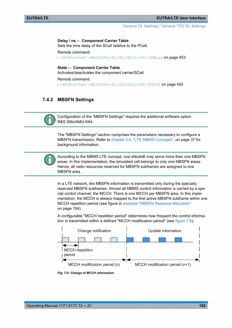
EUTRA/LTE User InterfaceEUTRA/LTE
102Operating Manual 1171.5177.12 ─ 21
Delay / ns ← Component Carrier TableSets the time delay of the SCell relative to the PCell.
Remote command: [:SOURce<hw>]: BB:EUTRa: DL:CA: CELL<ch0>: TDELay on page 453
State ← Component Carrier TableActivates/deactivates the component carrier/SCell.
Remote command: [:SOURce<hw>]: BB:EUTRa: DL:CA: CELL<ch0>: STATe on page 452
7.4.2 MBSFN Settings
Configuration of the "MBSFN Settings" requires the additional software optionR&S SMx/AMU-K84.
The "MBSFN Settings" section comprises the parameters necessary to configure aMBSFN transmission. Refer to chapter 3.4, "LTE MBMS Concepts", on page 37 forbackground information.
According to the MBMS LTE concept, one eNodeB may serve more than one MBSFNareas. In this implementation, the simulated cell belongs to only one MBSFN areas.Hence, all radio resources reserved for MBSFN subframes are assigned to oneMBSFN area.
In a LTE network, the MBSFN information is transmitted only during the speciallyreserved MBSFN subframes. Almost all MBMS control information is carried by a spe-cial control channel, the MCCH. There is one MCCH per MBSFN area. In this imple-mentation, the MCCH is always mapped to the first active MBSFN subframe within oneMCCH repetition period (see figure in example "MBSFN Resource Allocation"on page 104).
A configurable "MCCH repetition period" determines how frequent the control informa-tion is transmitted within a defined "MCCH modification period" (see figure 7-6).
Fig. 7-6: Change of MCCH information
General DL Settings / General TDD DL Settings
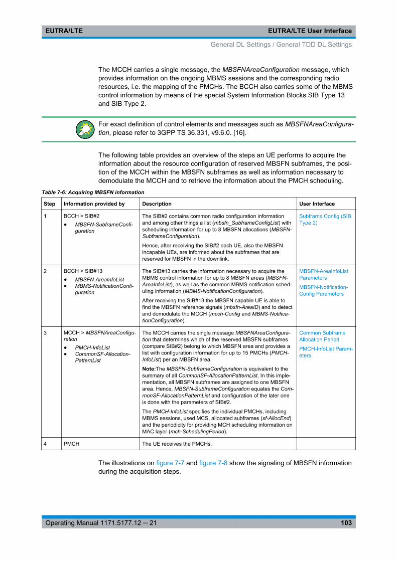
EUTRA/LTE User InterfaceEUTRA/LTE
103Operating Manual 1171.5177.12 ─ 21
The MCCH carries a single message, the MBSFNAreaConfiguration message, whichprovides information on the ongoing MBMS sessions and the corresponding radioresources, i.e. the mapping of the PMCHs. The BCCH also carries some of the MBMScontrol information by means of the special System Information Blocks SIB Type 13and SIB Type 2.
For exact definition of control elements and messages such as MBSFNAreaConfigura-tion, please refer to 3GPP TS 36.331, v9.6.0. [16].
The following table provides an overview of the steps an UE performs to acquire theinformation about the resource configuration of reserved MBSFN subframes, the posi-tion of the MCCH within the MBSFN subframes as well as information necessary todemodulate the MCCH and to retrieve the information about the PMCH scheduling.
Table 7-6: Acquiring MBSFN information
Step Information provided by Description User Interface
1 BCCH > SIB#2● MBSFN-SubframeConfi-
guration
The SIB#2 contains common radio configuration informationand among other things a list (mbsfn_SubframeConfigList) withscheduling information for up to 8 MBSFN allocations (MBSFN-SubframeConfiguration).
Hence, after receiving the SIB#2 each UE, also the MBSFNincapable UEs, are informed about the subframes that arereserved for MBSFN in the downlink.
Subframe Config (SIBType 2)
2 BCCH > SIB#13● MBSFN-AreaInfoList● MBMS-NotificationConfi-
guration
The SIB#13 carries the information necessary to acquire theMBMS control information for up to 8 MBSFN areas (MBSFN-AreaInfoList), as well as the common MBMS notification sched-uling information (MBMS-NotificationConfiguration).
After receiving the SIB#13 the MBSFN capable UE is able tofind the MBSFN reference signals (mbsfn-AreaID) and to detectand demodulate the MCCH (mcch-Config and MBMS-Notifica-tionConfiguration).
MBSFN-AreaInfoListParameters
MBSFN-Notification-Config Parameters
3 MCCH > MBSFNAreaConfigu-ration● PMCH-InfoList● CommonSF-Allocation-
PatternList
The MCCH carries the single message MBSFNAreaConfigura-tion that determines which of the reserved MBSFN subframes(compare SIB#2) belong to which MBSFN area and provides alist with configuration information for up to 15 PMCHs (PMCH-InfoList) per an MBSFN area.
Note:The MBSFN-SubframeConfiguration is equivalent to thesummary of all CommonSF-AllocationPatternList. In this imple-mentation, all MBSFN subframes are assigned to one MBSFNarea. Hence, MBSFN-SubframeConfiguration equates the Com-monSF-AllocationPatternList and configuration of the later oneis done with the parameters of SIB#2.
The PMCH-InfoList specifies the individual PMCHs, includingMBMS sessions, used MCS, allocated subframes (sf-AllocEnd)and the periodicity for providing MCH scheduling information onMAC layer (mch-SchedulingPeriod).
Common SubframeAllocation Period
PMCH-InfoList Param-eters
4 PMCH The UE receives the PMCHs.
The illustrations on figure 7-7 and figure 7-8 show the signaling of MBSFN informationduring the acquisition steps.
General DL Settings / General TDD DL Settings
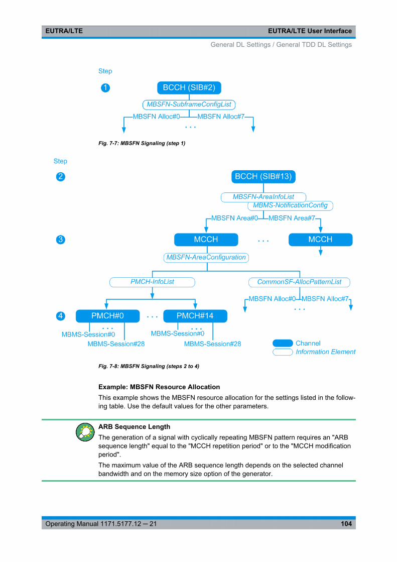
EUTRA/LTE User InterfaceEUTRA/LTE
104Operating Manual 1171.5177.12 ─ 21
Fig. 7-7: MBSFN Signaling (step 1)
Fig. 7-8: MBSFN Signaling (steps 2 to 4)
Example: MBSFN Resource AllocationThis example shows the MBSFN resource allocation for the settings listed in the follow-ing table. Use the default values for the other parameters.
ARB Sequence LengthThe generation of a signal with cyclically repeating MBSFN pattern requires an "ARBsequence length" equal to the "MCCH repetition period" or to the "MCCH modificationperiod".The maximum value of the ARB sequence length depends on the selected channelbandwidth and on the memory size option of the generator.
General DL Settings / General TDD DL Settings
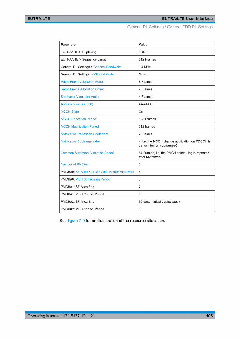
EUTRA/LTE User InterfaceEUTRA/LTE
105Operating Manual 1171.5177.12 ─ 21
Parameter Value
EUTRA/LTE > Duplexing FDD
EUTRA/LTE > Sequence Length 512 Frames
General DL Settings > Channel Bandwidth 1.4 MHz
General DL Settings > MBSFN Mode Mixed
Radio Frame Allocation Period 8 Frames
Radio Frame Allocation Offset 2 Frames
Subframe Allocation Mode 4 Frames
Allocation value (HEX) AAAAAA
MCCH State On
MCCH Repetition Period 128 Frames
MCCH Modification Period 512 frames
Notification Repetition Coefficient 2 Frames
Notification Subframe Index 4, i.e. the MCCH change notification on PDCCH istransmitted on subframe#6
Common Subframe Allocation Period 64 Frames, i.e. the PMCH scheduling is repeatedafter 64 frames
Number of PMCHs 3
PMCH#0: SF Alloc Start/SF Alloc EndSF Alloc End 5
PMCH#0: MCH Scheduling Period 8
PMCH#1: SF Alloc End 7
PMCH#1: MCH Sched. Period 8
PMCH#2: SF Alloc End 95 (automatically calculated)
PMCH#2: MCH Sched. Period 8
See figure 7-9 for an illustaration of the resource allocation.
General DL Settings / General TDD DL Settings
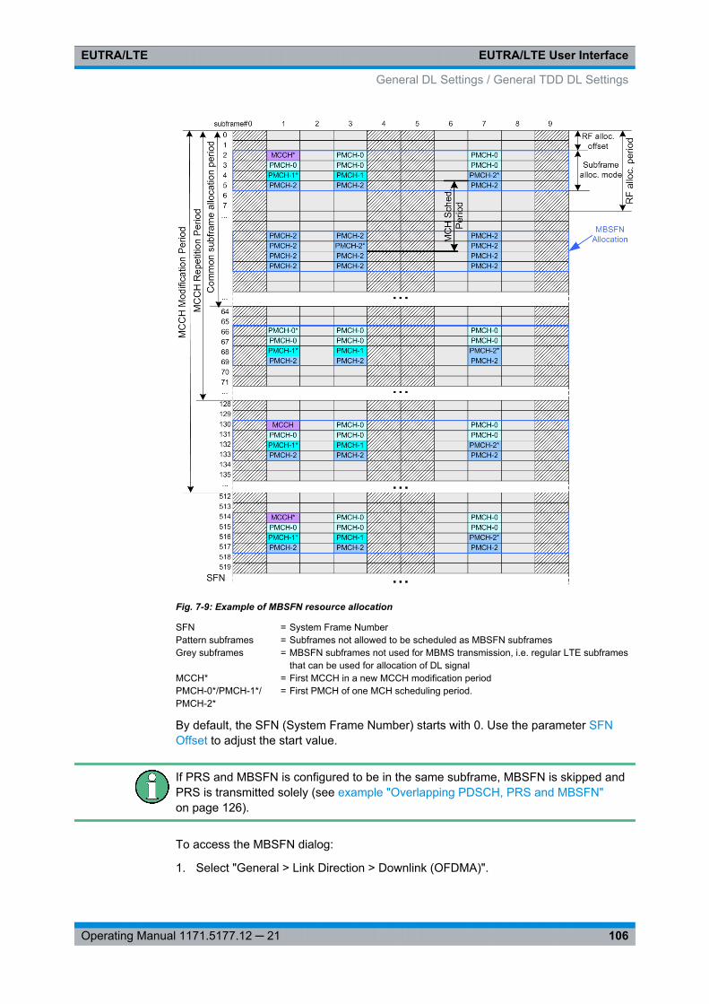
EUTRA/LTE User InterfaceEUTRA/LTE
106Operating Manual 1171.5177.12 ─ 21
Fig. 7-9: Example of MBSFN resource allocation
SFN = System Frame NumberPattern subframes = Subframes not allowed to be scheduled as MBSFN subframesGrey subframes = MBSFN subframes not used for MBMS transmission, i.e. regular LTE subframes
that can be used for allocation of DL signalMCCH* = First MCCH in a new MCCH modification periodPMCH-0*/PMCH-1*/PMCH-2*
= First PMCH of one MCH scheduling period.
By default, the SFN (System Frame Number) starts with 0. Use the parameter SFNOffset to adjust the start value.
If PRS and MBSFN is configured to be in the same subframe, MBSFN is skipped andPRS is transmitted solely (see example "Overlapping PDSCH, PRS and MBSFN"on page 126).
To access the MBSFN dialog:
1. Select "General > Link Direction > Downlink (OFDMA)".
General DL Settings / General TDD DL Settings
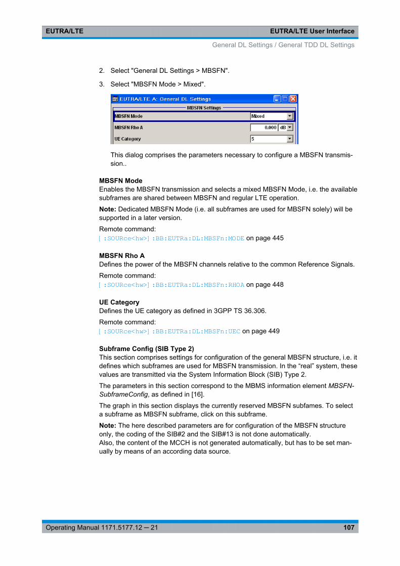
EUTRA/LTE User InterfaceEUTRA/LTE
107Operating Manual 1171.5177.12 ─ 21
2. Select "General DL Settings > MBSFN".
3. Select "MBSFN Mode > Mixed".
This dialog comprises the parameters necessary to configure a MBSFN transmis-sion..
MBSFN ModeEnables the MBSFN transmission and selects a mixed MBSFN Mode, i.e. the availablesubframes are shared between MBSFN and regular LTE operation.
Note: Dedicated MBSFN Mode (i.e. all subframes are used for MBSFN solely) will besupported in a later version.
Remote command: [:SOURce<hw>]: BB:EUTRa: DL: MBSFn:MODE on page 445
MBSFN Rho ADefines the power of the MBSFN channels relative to the common Reference Signals.
Remote command: [:SOURce<hw>]: BB:EUTRa: DL:MBSFn:RHOA on page 448
UE CategoryDefines the UE category as defined in 3GPP TS 36.306.
Remote command: [:SOURce<hw>]: BB:EUTRa: DL:MBSFn: UEC on page 449
Subframe Config (SIB Type 2)This section comprises settings for configuration of the general MBSFN structure, i.e. itdefines which subframes are used for MBSFN transmission. In the “real” system, thesevalues are transmitted via the System Information Block (SIB) Type 2.
The parameters in this section correspond to the MBMS information element MBSFN-SubframeConfig, as defined in [16].
The graph in this section displays the currently reserved MBSFN subfames. To selecta subframe as MBSFN subframe, click on this subframe.
Note: The here described parameters are for configuration of the MBSFN structureonly, the coding of the SIB#2 and the SIB#13 is not done automatically.Also, the content of the MCCH is not generated automatically, but has to be set man-ually by means of an according data source.
General DL Settings / General TDD DL Settings
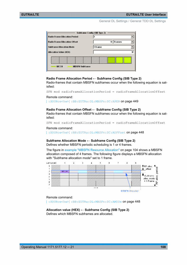
EUTRA/LTE User InterfaceEUTRA/LTE
108Operating Manual 1171.5177.12 ─ 21
Radio Frame Allocation Period ← Subframe Config (SIB Type 2)Radio-frames that contain MBSFN subframes occur when the following equation is sat-isfied:SFN mod radioFrameAllocationPeriod = radioFrameAllocationOffsetRemote command: [:SOURce<hw>]: BB:EUTRa: DL:MBSFn: SC:APER on page 449
Radio Frame Allocation Offset ← Subframe Config (SIB Type 2)Radio-frames that contain MBSFN subframes occur when the following equation is sat-isfied:SFN mod radioFrameAllocationPeriod = radioFrameAllocationOffsetRemote command: [:SOURce<hw>]: BB:EUTRa: DL: MBSFn:SC: AOFFset on page 448
Subframe Allocation Mode ← Subframe Config (SIB Type 2)Defines whether MBSFN periodic scheduling is 1 or 4 frames.
The figure in example "MBSFN Resource Allocation" on page 104 shows a MBSFNallocation composed of 4 frames. The following figure displays a MBSFN allocationwith "Subframe allocation mode" set to 1 frame.
Remote command: [:SOURce<hw>]: BB: EUTRa:DL: MBSFn:SC:AMODe on page 448
Allocation value (HEX) ← Subframe Config (SIB Type 2)Defines which MBSFN subframes are allocated.
General DL Settings / General TDD DL Settings
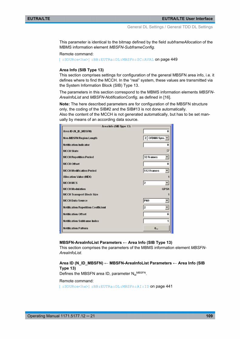
EUTRA/LTE User InterfaceEUTRA/LTE
109Operating Manual 1171.5177.12 ─ 21
This parameter is identical to the bitmap defined by the field subframeAllocation of theMBMS information element MBSFN-SubframeConfig.
Remote command: [:SOURce<hw>]: BB: EUTRa:DL: MBSFn:SC:AVAL on page 449
Area Info (SIB Type 13)This section comprises settings for configuration of the general MBSFN area info, i.e. itdefines where to find the MCCH. In the “real” system, these values are transmitted viathe System Information Block (SIB) Type 13.
The parameters in this section correspond to the MBMS information elements MBSFN-AreaInfoList and MBSFN-NotificationConfig, as defined in [16].
Note: The here described parameters are for configuration of the MBSFN structureonly, the coding of the SIB#2 and the SIB#13 is not done automatically.Also the content of the MCCH is not generated automatically, but has to be set man-ually by means of an according data source.
MBSFN-AreaInfoList Parameters ← Area Info (SIB Type 13)This section comprises the parameters of the MBMS information element MBSFN-AreaInfoList.
Area ID (N_ID_MBSFN) ← MBSFN-AreaInfoList Parameters ← Area Info (SIBType 13)Defines the MBSFN area ID, parameter Nid
MBSFN.
Remote command: [: SOURce<hw>]: BB:EUTRa: DL:MBSFn: AI:ID on page 441
General DL Settings / General TDD DL Settings
EUTRA/LTE User InterfaceEUTRA/LTE
110Operating Manual 1171.5177.12 ─ 21
Non-MBSFN Region Length ← MBSFN-AreaInfoList Parameters ← Area Info (SIBType 13)Defines how many symbols from the beginning of the subframe constitute the non-MBSFN region.
Remote command: [:SOURce<hw>]: BB: EUTRa:DL: MBSFn:AI:NMRL on page 445
Notification Indicator ← MBSFN-AreaInfoList Parameters ← Area Info (SIB Type13)Defines which PDCCH bit is used to notify the UE about change of the MCCH applica-ble for this MBSFN area. Value 0 corresponds to the least significant bit as defined forthe DCI Format 1C.
Remote command: [:SOURce<hw>]: BB:EUTRa: DL:MBSFn:AI: NIND on page 445
MCCH State ← MBSFN-AreaInfoList Parameters ← Area Info (SIB Type 13)Enables/disables the MCCH.
Remote command: [:SOURce<hw>]: BB: EUTRa:DL: MBSFn:AI: MCCH:STATe on page 444
MCCH Repetition Period ← MBSFN-AreaInfoList Parameters ← Area Info (SIBType 13)Defines the interval between transmissions of MCCH information in radio frames.
Remote command: [: SOURce<hw>]: BB:EUTRa: DL:MBSFn: AI:MCCH: RPER on page 444
MCCH Offset ← MBSFN-AreaInfoList Parameters ← Area Info (SIB Type 13)Indicates, together with the "MCCH repetition period", the radio frames in which MCCHis scheduled. MCCH is scheduled in radio frames for which:
SFN mod "MCCH repetition period" = "MCCH offset"
Remote command: [: SOURce<hw>]: BB:EUTRa: DL:MBSFn:AI: MCCH:OFFS on page 443
MCCH Modification Period ← MBSFN-AreaInfoList Parameters ← Area Info (SIBType 13)Defines periodically appearing boundaries, i.e. radio frames for which the followingequation is fulfilled:
SFN mod "MCCH modification period" = 0
The contents of different transmissions of MCCH information can only be different ifthere is at least one such boundary in-between them.
Remote command: [:SOURce<hw>]: BB: EUTRa:DL:MBSFn: AI:MCCH: MPER on page 442
General DL Settings / General TDD DL Settings
EUTRA/LTE User InterfaceEUTRA/LTE
111Operating Manual 1171.5177.12 ─ 21
Allocation Value (HEX) ← MBSFN-AreaInfoList Parameters ← Area Info (SIBType 13)Indicates the subframes of the radio frames indicated by the "MCCH repetition period"and the "MCCH offset", that may carry MCCH.
Note: In the current implementation, the MCCH is always mapped to the first activeMBSFN subframe.
Remote command: [:SOURce<hw>]: BB:EUTRa: DL:MBSFn: AI:MCCH:AVAL? on page 441
MCCH MCS ← MBSFN-AreaInfoList Parameters ← Area Info (SIB Type 13)Defines the Modulation and Coding Scheme (MCS) applicable for the subframes indi-cated by the "MCCH Allocation value" and for the first subframe of each MCH schedul-ing period (which may contain the MCH scheduling information provided by MAC).
Remote command: [:SOURce<hw>]: BB:EUTRa: DL:MBSFn: AI:MCCH:MCS on page 442
MCCS Modulation ← MBSFN-AreaInfoList Parameters ← Area Info (SIB Type 13)Displays the values as determined by the "MCCH MCS".
Remote command: [:SOURce<hw>]: BB:EUTRa: DL:MBSFn: AI:MCCH: MODulation? on page 442
MCCH Transport Block Size ← MBSFN-AreaInfoList Parameters ← Area Info (SIBType 13)Displays the values as determined by the "MCCH MCS".
Remote command: [:SOURce<hw>]: BB: EUTRa:DL: MBSFn:AI:MCCH: TBSize? on page 444
MCCH Data Source ← MBSFN-AreaInfoList Parameters ← Area Info (SIB Type13)Sets the data source used for the MCCH.
Remote command: [:SOURce<hw>]: BB:EUTRa: DL:MBSFn: AI:MCCH:DATA on page 441[:SOURce<hw>]: BB:EUTRa: DL:MBSFn: AI:MCCH:DLISt on page 441[:SOURce<hw>]: BB:EUTRa: DL:MBSFn: AI:MCCH:PATTern on page 444
MBSFN-NotificationConfig Parameters ← Area Info (SIB Type 13)This section comprises the parameters of the MBMS information element MBSFN-Noti-ficationConfig.
Notification Repetition Coefficient ← MBSFN-NotificationConfig Parameters ←Area Info (SIB Type 13)Selects the current change notification repetition period common for all MCCHs thatare configured. The notification repetition period is calculated as follow:
change notification repetition period = shortest modification period/ "Notification repeti-tion coefficient"
General DL Settings / General TDD DL Settings
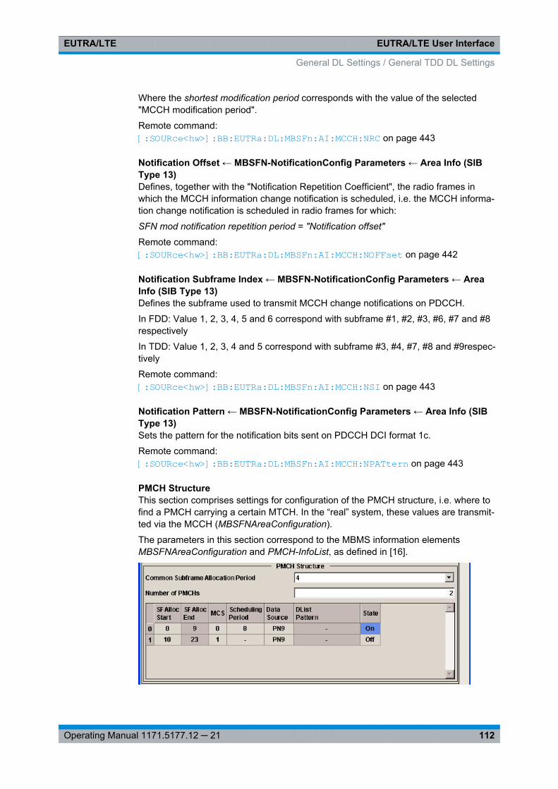
EUTRA/LTE User InterfaceEUTRA/LTE
112Operating Manual 1171.5177.12 ─ 21
Where the shortest modification period corresponds with the value of the selected"MCCH modification period".
Remote command: [:SOURce<hw>]: BB: EUTRa:DL: MBSFn:AI:MCCH: NRC on page 443
Notification Offset ← MBSFN-NotificationConfig Parameters ← Area Info (SIBType 13)Defines, together with the "Notification Repetition Coefficient", the radio frames inwhich the MCCH information change notification is scheduled, i.e. the MCCH informa-tion change notification is scheduled in radio frames for which:
SFN mod notification repetition period = "Notification offset"
Remote command: [:SOURce<hw>]: BB:EUTRa: DL:MBSFn: AI:MCCH: NOFFset on page 442
Notification Subframe Index ← MBSFN-NotificationConfig Parameters ← AreaInfo (SIB Type 13)Defines the subframe used to transmit MCCH change notifications on PDCCH.
In FDD: Value 1, 2, 3, 4, 5 and 6 correspond with subframe #1, #2, #3, #6, #7 and #8respectively
In TDD: Value 1, 2, 3, 4 and 5 correspond with subframe #3, #4, #7, #8 and #9respec-tively
Remote command: [:SOURce<hw>]: BB:EUTRa: DL:MBSFn: AI:MCCH: NSI on page 443
Notification Pattern ← MBSFN-NotificationConfig Parameters ← Area Info (SIBType 13)Sets the pattern for the notification bits sent on PDCCH DCI format 1c.
Remote command: [: SOURce<hw>]: BB:EUTRa: DL:MBSFn: AI:MCCH:NPATtern on page 443
PMCH StructureThis section comprises settings for configuration of the PMCH structure, i.e. where tofind a PMCH carrying a certain MTCH. In the “real” system, these values are transmit-ted via the MCCH (MBSFNAreaConfiguration).
The parameters in this section correspond to the MBMS information elementsMBSFNAreaConfiguration and PMCH-InfoList, as defined in [16].
General DL Settings / General TDD DL Settings
EUTRA/LTE User InterfaceEUTRA/LTE
113Operating Manual 1171.5177.12 ─ 21
Common Subframe Allocation Period ← PMCH StructureDefines the period during which resources corresponding with field commonSF-Allocare divided between the (P)MCH that are configured for this MBSFN area.
The subframe allocation patterns, as defined by commonSF-Alloc, repeat continuouslyduring this period.
Remote command: [:SOURce<hw>]: BB:EUTRa: DL:MBSFn: MTCH:CSAP on page 445
PMCH-InfoList Parameters ← PMCH StructureComprises the parameters of the PMCH-InfoList.
Number of PMCHs ← PMCH-InfoList Parameters ← PMCH StructureDefines the number of PMCHs in this MBSFN area.
Remote command: [:SOURce<hw>]: BB: EUTRa:DL:MBSFn: MTCH: NPMChs on page 446
SF Alloc Start/SF Alloc End ← PMCH-InfoList Parameters ← PMCH StructureDefines the first/last subframe allocated to this (P)MCH within a period identified byfield commonSF-Alloc.
The subframes allocated to (P)MCH corresponding with the nth entry in pmch-InfoListare the subsequent subframes starting from either the subframe identified by "SF AllocEnd" of the (–1)th listed (P)MCH or, for n=1, the first subframe, through the subframeidentified by "SF Alloc End" of the nth listed (P)MCH. Value 0 corresponds with the firstsubframe defined by field commonSF-Alloc.
Note: Configuring the MCHs ("SF Alloc Start" values) from bottom to top. Although the3GPP specification defines the "SF Alloc End" parameter as the only one required, inthis implementation it is mandatory to define the "SF Alloc Start" instead.The implemented algorithm uses the selected "SF Alloc Start" and calculates automati-cally the "SF Alloc End" of the corresponding MCH. The algorithm applies the internalrule, that there will be no gap between two consequent MCHs.It is therefore recommended to configure the MCHs, i.e. define the "SF Alloc Start" val-ues, from bottom to the top. This workaround prevents the configuration of overlappingMCHs.
Remote command: [:SOURce<hw>]: BB:EUTRa: DL:MBSFn: PMCH<ch0>: SASTart on page 447[: SOURce<hw>]: BB:EUTRa: DL:MBSFn: PMCH<ch0>: SAENd on page 447
MCS ← PMCH-InfoList Parameters ← PMCH StructureDefines the value for parameter according to [5] Table 7.1.7.1-1, which defines theModulation and Coding Scheme (MCS) applicable for the subframes of this (P)MCH asindicated by the field commonSF-Alloc. The MCS does however neither apply to thesubframes that may carry MCCH, i.e. the subframes indicated by the field sf-AllocInfowithin System Information Block Type 13, nor for the first subframe of each MCHscheduling period (which may contain the MCH scheduling information provided byMAC).
Remote command: [:SOURce<hw>]: BB:EUTRa: DL:MBSFn: PMCH<ch0>: MCS on page 447
General DL Settings / General TDD DL Settings
EUTRA/LTE User InterfaceEUTRA/LTE
114Operating Manual 1171.5177.12 ─ 21
MCH Scheduling Period ← PMCH-InfoList Parameters ← PMCH StructureDefines the MCH scheduling period, i.e. the periodicity used for providing MCH sched-uling information at lower layers (MAC) applicable for an MCH.
Note: The first subframe of the scheduling period may contain the MAC control ele-ment and therefore uses MCS of MCCH (however, the data source from PMCH is stillused).
Remote command: [:SOURce<hw>]: BB:EUTRa: DL:MBSFn: PMCH<ch0>: SPERiod on page 447
Data Source ← PMCH-InfoList Parameters ← PMCH StructureSets the data source for this PMCH/MTCH.
Remote command: [:SOURce<hw>]: BB:EUTRa: DL:MBSFn: PMCH<ch0>: DATA on page 446[:SOURce<hw>]: BB:EUTRa: DL:MBSFn: PMCH<ch0>: DLISt on page 446[:SOURce<hw>]: BB:EUTRa: DL:MBSFn: PMCH<ch0>: PATTern on page 447
State ← PMCH-InfoList Parameters ← PMCH StructureEnables/disables the selected PMCH/MTCH.
Remote command: [:SOURce<hw>]: BB:EUTRa: DL:MBSFn: PMCH<ch0>: STATe on page 446
7.4.3 Physical Settings
In the "Physical Settings" section, the channel bandwidth respectively the number ofresource blocks per slot is selected. The other parameters are fixed and read-only.
Channel BandwidthSets the channel bandwidth of the EUTRA/LTE system.
Although the 3GPP specification bases on bandwidth agonistic layer 1 and channelbandwidth is determined by specifying the desired number of resource blocks, the cur-rent EUTRA standardization focuses on six bandwidths (1.4, 3, 5, 10, 15 and 20 MHz).
For backward compatibility with previous version of this software, this parameter allowsthe flexibility to choose, whether a user defined bandwidth or one of the pre-definedchannel bandwidths is used.
If a pre-defined channel bandwidth is selected; the actual "Number of Resource BlocksPer Slot" is internally calculated for the selected "Channel Bandwidth" and "PhysicalResource Block Bandwidth".
The sampling rate, occupied bandwidth and FFT size are therefore determined by theparameter "Number of Resource Blocks Per Slot". If required, the FFT Size can beadjusted.
See also table 4-1 for an overview of this cross-reference between the parameters.
Remote command: [:SOURce<hw>]: BB: EUTRa:DL:BW on page 407
General DL Settings / General TDD DL Settings
EUTRA/LTE User InterfaceEUTRA/LTE
115Operating Manual 1171.5177.12 ─ 21
Physical Resource Block BandwidthDisplays the bandwidth of one physical resource block.
Note: In this release, this value is fixed to 12 x 15 kHz.
Remote command: n.a.
Number of Resource Blocks Per SlotThis parameter determines the channel bandwidth.
If the parameter "Channel Bandwidth" is set to one of the pre-defined channel band-widths (1.4, 3, 5, 10, 15 or 20 MHz), the value "Number of Resource Blocks Per Slot" isread only and is automatically set according to the selected channel bandwidth and"Physical Resource Block Bandwidth".
If a user defined channel bandwidth is selected, the parameters "Number of ResourceBlocks Per Slot" and "Physical Resource Blocks Bandwidth" determine the actualchannel bandwidth.
However, the sampling rate and the occupied bandwidth are determined by the param-eter "Number of Resource Blocks Per Slot". If required, the FFT Size can be adjusted.
See also table 4-1 for an overview of this cross-reference between the parameters.
Remote command: [:SOURce<hw>]: BB:EUTRa: DL:NORB on page 408
FFT SizeSets the FFT (Fast Fourier Transformation) size.
The FFT size can be freely selected for all bandwidth definitions under the followingconstrains:● For a specific bandwidth, all FFT sizes are applicable as long as the size is greater
than the number of occupied subcarriers.By default, the smallest available FFT size is selected.
● To decrease the number of unused guard subcarriers and the resulting samplingrate, for channel bandwidth of 15 MHz a DFT size of 1536 is provided along withthe default FFT size of 2048.
See also table 4-1 for an overview of the cross-reference between the parameter andthe available FFT sizes.
Remote command: [:SOURce<hw>]: BB:EUTRa: DL:FFT on page 408
Occupied BandwidthDisplays the occupied bandwidth. The value is automatically set according to theparameter "Number of Resource Blocks Per Slot".
Remote command: [: SOURce<hw>]: BB:EUTRa: DL:OCCBandwidth? on page 409
General DL Settings / General TDD DL Settings
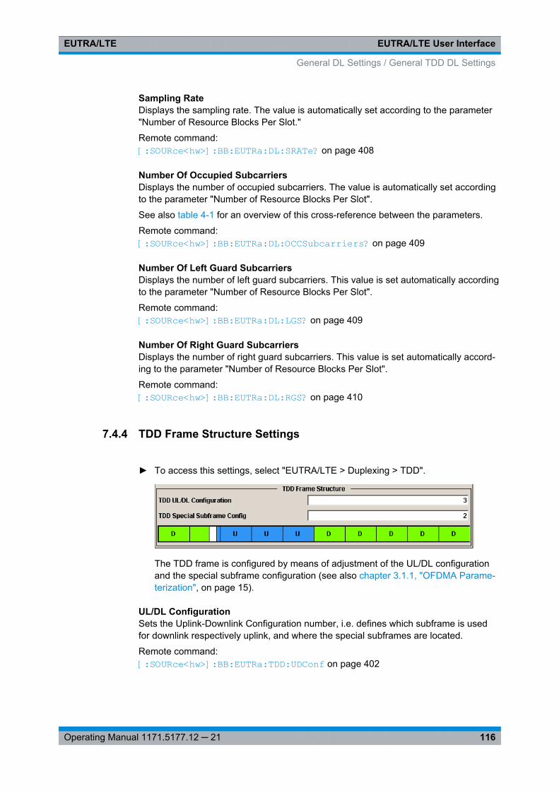
EUTRA/LTE User InterfaceEUTRA/LTE
116Operating Manual 1171.5177.12 ─ 21
Sampling RateDisplays the sampling rate. The value is automatically set according to the parameter"Number of Resource Blocks Per Slot."
Remote command: [:SOURce<hw>]: BB:EUTRa: DL:SRATe? on page 408
Number Of Occupied SubcarriersDisplays the number of occupied subcarriers. The value is automatically set accordingto the parameter "Number of Resource Blocks Per Slot".
See also table 4-1 for an overview of this cross-reference between the parameters.
Remote command: [:SOURce<hw>]: BB: EUTRa:DL:OCCSubcarriers? on page 409
Number Of Left Guard SubcarriersDisplays the number of left guard subcarriers. This value is set automatically accordingto the parameter "Number of Resource Blocks Per Slot".
Remote command: [:SOURce<hw>]: BB: EUTRa:DL:LGS? on page 409
Number Of Right Guard SubcarriersDisplays the number of right guard subcarriers. This value is set automatically accord-ing to the parameter "Number of Resource Blocks Per Slot".
Remote command: [: SOURce<hw>]: BB:EUTRa: DL:RGS? on page 410
7.4.4 TDD Frame Structure Settings
► To access this settings, select "EUTRA/LTE > Duplexing > TDD".
The TDD frame is configured by means of adjustment of the UL/DL configurationand the special subframe configuration (see also chapter 3.1.1, "OFDMA Parame-terization", on page 15).
UL/DL ConfigurationSets the Uplink-Downlink Configuration number, i.e. defines which subframe is usedfor downlink respectively uplink, and where the special subframes are located.
Remote command: [:SOURce<hw>]: BB: EUTRa:TDD: UDConf on page 402
General DL Settings / General TDD DL Settings
EUTRA/LTE User InterfaceEUTRA/LTE
117Operating Manual 1171.5177.12 ─ 21
Configuration of Special SubframesSets the Special Subframe Configuration number, i.e. together with the parameterCyclic Prefix defines the lengths of the DwPTS, the Guard Period and the UpPTS.
The DwPTS length selected with this parameter determines the maximum number ofthe OFDM symbols available for PDSCH in the special subframe.
The UpPTS length selected with this parameter determines the maximum number ofthe SC-FDMA symbols available for SRS in the special subframe.
Remote command: [:SOURce<hw>]: BB:EUTRa: TDD:SPSConf on page 402
7.4.5 Scheduling Settings
In the "Scheduling" section, you define whether the PDSCH Scheduling is performedmanually or according to the configuration made for the DCIs.
PDSCH SchedulingDetermines whether the configuration and scheduling of the different PDSCH alloca-tions inside of the DL allocation table is performed manually or according to the config-uration made for the DCIs.
Note: Switching from "Auto/DCI" mode to "Manual" mode enables all parameters in theDL allocation table for configuration without to change their values. Switching from"Manual" to "Auto/DCI" mode, however, triggers a reset of the frame prior to reconfigu-ration of the PDSCH allocations according to the settings made for the PDCCH DCIs,i.e. the settings made in the DL allocation table are lost.
"Manual" In this default mode, there is no cross-reference between the settingsmade for the PDCCH DCIs and the PDSCHs settings. The PDSCHallocations have to be configured manually in the DL allocation table.
General DL Settings / General TDD DL Settings
EUTRA/LTE User InterfaceEUTRA/LTE
118Operating Manual 1171.5177.12 ─ 21
"Auto/DCI" Precoding for spatial multiplexing will be performed according to3GPP TS 36.211 and the selected parameters.This mode assures a 3GPP compliant EUTRA/LTE signal and thePDSCH allocations are configured automatically according to theconfiguration of the PDCCH DCIs.
The generation of a compliant signal requires some limitations in theconfiguration flexibility, especially regarding the power setting:● The value of the parameter Reference Signal Power is fixed to
0dB.● The PDSCH Rho A of each allocation belonging to a user is set
as configured with the parameter P_A for the corresponding userin the "Configure User" dialog.
● All four users are activated with enabled Scrambling and ChannelCoding.
Not all combinations of DCI Table, Users and UE_ID/n_RNTI areallowed. The table 7-7 shows this dependency.Table 7-7: DCI Formats dependencies
User UE ID/n_RNTI DCI Format
User 1 .. 4 As defined for the corresponding user 0,1,1a,1b,1d,2,2a,2c,3,3a
P-RNTI 65534 1a,1c
SI-RNTI 65535
RA-RNTI As defined with the parameter RA_RNTIin the "General DL Setting" dialog
Remote command: [:SOURce<hw>]: BB: EUTRa:DL: CONF:MODE on page 404
7.4.6 MIMO
In the MIMO section, the MIMO configuration and the simulated antennas are defined.
Provided are the following settings:
Global MIMO ConfigurationDetermines the number of transmit antennas of the simulated EUTRA/LTE system.Depending on this parameter, the Downlink Reference Signal Structure will be setaccordingly (see also figure 3-9).
Note: One baseband simulates one antenna.
"1 TxAntenna" Enables single antenna port transmission.
"2 TxAntennas/4 TxAntennas"Enables a multiple antenna transmission. The transmission mode,transmit diversity or spatial multiplexing, is determined per allocationwith the parameter Precoding Scheme.
General DL Settings / General TDD DL Settings
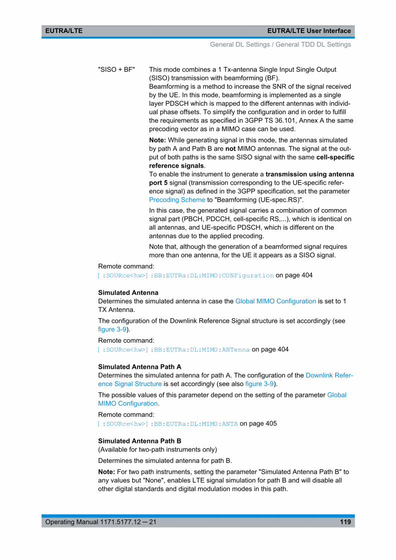
EUTRA/LTE User InterfaceEUTRA/LTE
119Operating Manual 1171.5177.12 ─ 21
"SISO + BF" This mode combines a 1 Tx-antenna Single Input Single Output(SISO) transmission with beamforming (BF).Beamforming is a method to increase the SNR of the signal receivedby the UE. In this mode, beamforming is implemented as a singlelayer PDSCH which is mapped to the different antennas with individ-ual phase offsets. To simplify the configuration and in order to fulfillthe requirements as specified in 3GPP TS 36.101, Annex A the sameprecoding vector as in a MIMO case can be used.
Note: While generating signal in this mode, the antennas simulatedby path A and Path B are not MIMO antennas. The signal at the out-put of both paths is the same SISO signal with the same cell-specificreference signals.To enable the instrument to generate a transmission using antennaport 5 signal (transmission corresponding to the UE-specific refer-ence signal) as defined in the 3GPP specification, set the parameterPrecoding Scheme to "Beamforming (UE-spec.RS)".In this case, the generated signal carries a combination of commonsignal part (PBCH, PDCCH, cell-specific RS,...), which is identical onall antennas, and UE-specific PDSCH, which is different on theantennas due to the applied precoding.Note that, although the generation of a beamformed signal requiresmore than one antenna, for the UE it appears as a SISO signal.
Remote command: [:SOURce<hw>]: BB: EUTRa:DL: MIMO:CONFiguration on page 404
Simulated AntennaDetermines the simulated antenna in case the Global MIMO Configuration is set to 1TX Antenna.
The configuration of the Downlink Reference Signal structure is set accordingly (seefigure 3-9).
Remote command: [: SOURce<hw>]: BB:EUTRa: DL:MIMO:ANTenna on page 404
Simulated Antenna Path ADetermines the simulated antenna for path A. The configuration of the Downlink Refer-ence Signal Structure is set accordingly (see also figure 3-9).
The possible values of this parameter depend on the setting of the parameter GlobalMIMO Configuration.
Remote command: [:SOURce<hw>]: BB: EUTRa:DL:MIMO: ANTA on page 405
Simulated Antenna Path B(Available for two-path instruments only)
Determines the simulated antenna for path B.
Note: For two path instruments, setting the parameter "Simulated Antenna Path B" toany values but "None", enables LTE signal simulation for path B and will disable allother digital standards and digital modulation modes in this path.
General DL Settings / General TDD DL Settings
EUTRA/LTE User InterfaceEUTRA/LTE
120Operating Manual 1171.5177.12 ─ 21
Enabling path B to simulate an antenna automatically couples path A and path B, i.e.path B is controlled via path A. The signal generated by path B has identical parame-ters with the settings made for path A and the downlink reference signal's parameters"First Reference Signal Position", "Subcarrier Offset" and "Use Second Reference Sig-nal" are set accordingly.
The configuration of the Downlink Reference Signal Structure is set accordingly (seealso figure 3-9).
The possible values of this parameter depend on the setting of the parameter GlobalMIMO Configuration.
Remote command: [:SOURce<hw>]: BB:EUTRa: DL:MIMO: ANTB on page 405
Antenna Port Mapping(enabled for instruments eqquiped with R&S SMx/AMU-K84/-K284)
Accesses the Cell Specific Antenna Port Mapping settings for defining the mapping ofthe logical antenna ports to the available physical Tx antennas.
7.4.7 Cell Specific Settings
In the "Cell Specific Settings" section, the physical layer cell identity settings and theDL power control settings are configured.
Cell IDSets the cell identity.
There are 504 unique physical layer cell identities (Cell ID), grouped into 168 uniquephysical cell identity groups that contain three unique identities each. The Cell ID iscalculated as following:
Cell ID = 3*Physical Cell ID Group + Physical Layer ID
There is a cross-reference between the values of this three parameters and changingof one of them results in adjustment in the values of the others.
The Cell ID determinates:● the downlink reference signal pseudo-random sequence,● the frequency shifts of the reference signal,● the S-SYNC sequence,● the cyclic shifts for PCFICH, PHICH and PDCCH mapping and● the pseudo-random sequence used for scrambling.
Remote command: [:SOURce<hw>]: BB:EUTRa: DL[:PLCI]:CID on page 410
Physical Cell ID GroupSets the physical cell identity group.
To configure these identities within a cell ID group, set the parameter Physical LayerID.
Remote command: [:SOURce<hw>]: BB:EUTRa:DL[: PLCI]:CIDGroup on page 410
General DL Settings / General TDD DL Settings
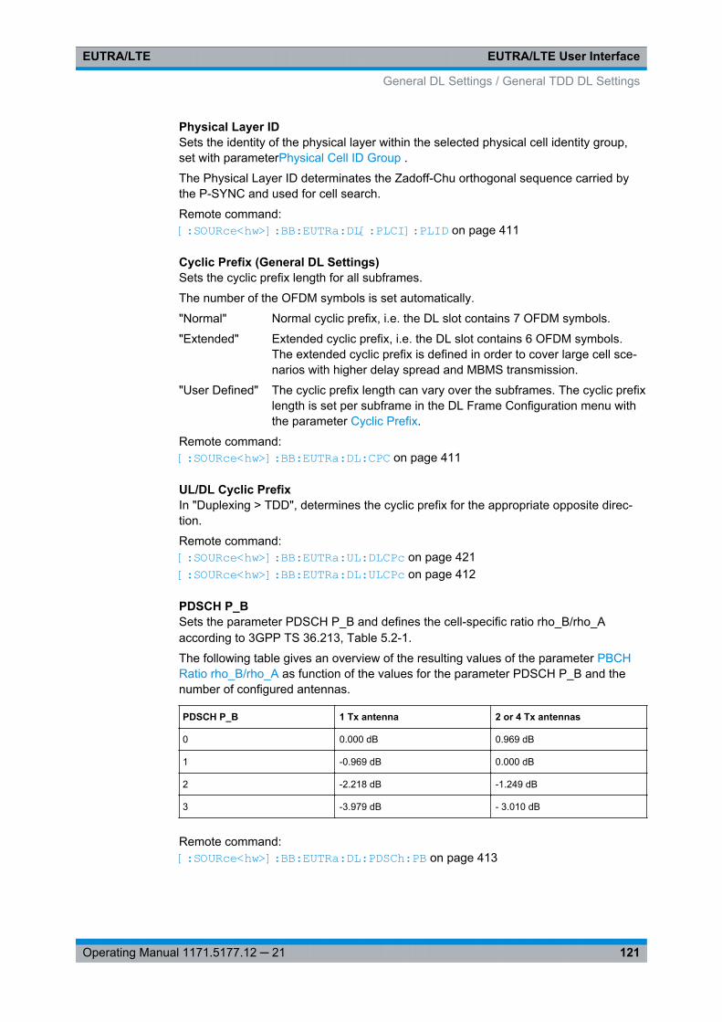
EUTRA/LTE User InterfaceEUTRA/LTE
121Operating Manual 1171.5177.12 ─ 21
Physical Layer IDSets the identity of the physical layer within the selected physical cell identity group,set with parameterPhysical Cell ID Group .
The Physical Layer ID determinates the Zadoff-Chu orthogonal sequence carried bythe P-SYNC and used for cell search.
Remote command: [: SOURce<hw>]: BB:EUTRa: DL[:PLCI]: PLID on page 411
Cyclic Prefix (General DL Settings)Sets the cyclic prefix length for all subframes.
The number of the OFDM symbols is set automatically.
"Normal" Normal cyclic prefix, i.e. the DL slot contains 7 OFDM symbols.
"Extended" Extended cyclic prefix, i.e. the DL slot contains 6 OFDM symbols.The extended cyclic prefix is defined in order to cover large cell sce-narios with higher delay spread and MBMS transmission.
"User Defined" The cyclic prefix length can vary over the subframes. The cyclic prefixlength is set per subframe in the DL Frame Configuration menu withthe parameter Cyclic Prefix.
Remote command: [:SOURce<hw>]: BB: EUTRa:DL: CPC on page 411
UL/DL Cyclic PrefixIn "Duplexing > TDD", determines the cyclic prefix for the appropriate opposite direc-tion.
Remote command: [:SOURce<hw>]: BB: EUTRa:UL:DLCPc on page 421[:SOURce<hw>]: BB: EUTRa:DL:ULCPc on page 412
PDSCH P_BSets the parameter PDSCH P_B and defines the cell-specific ratio rho_B/rho_Aaccording to 3GPP TS 36.213, Table 5.2-1.
The following table gives an overview of the resulting values of the parameter PBCHRatio rho_B/rho_A as function of the values for the parameter PDSCH P_B and thenumber of configured antennas.
PDSCH P_B 1 Tx antenna 2 or 4 Tx antennas
0 0.000 dB 0.969 dB
1 -0.969 dB 0.000 dB
2 -2.218 dB -1.249 dB
3 -3.979 dB - 3.010 dB
Remote command: [:SOURce<hw>]: BB: EUTRa:DL: PDSCh:PB on page 413
General DL Settings / General TDD DL Settings
EUTRA/LTE User InterfaceEUTRA/LTE
122Operating Manual 1171.5177.12 ─ 21
PDSCH Ratio rho_B/rho_ADisplays the transmit energy ratio among the resource elements allocated for PDSCHin the OFDM symbols containing reference signal (P_B) and such not containing one(P_A).
The value displayed is determined by the parameter PDSCH P_B and additionallydepends on the number of configured antennas.
Remote command: [:SOURce<hw>]: BB:EUTRa:DL: PDSCh:RATBa on page 413
PDCCH Ratio rho_B/rho_ASets the transmit energy ratio among the resource elements allocated for PDCCH inthe OFDM symbols containing reference signal (P_B) and such not containing one(P_A).
Remote command: [:SOURce<hw>]: BB:EUTRa: DL:PDCCh: RATBa on page 412
PBCH Ratio rho_B/rho_ASets the transmit energy ratio among the resource elements allocated for PBCH in theOFDM symbols containing reference signal (P_B) and such not containing one (P_A).
Remote command: [: SOURce<hw>]: BB:EUTRa: DL:PBCH:RATBa on page 412
PHICH DurationSets the PHICH duration, i.e. the allocation of the PHICH resource element groupsover the OFDM symbols.
The value selected puts the lower limit of the size of the PCFICH Settings that is sig-naled by the PCFICH.
"Normal" All resources element groups of PHICH (see Number of PHICHGroups) are allocated on the first OFDM symbol (OFDM Symbol 0).
"Extended" The resources element groups of PHICH are distributed over threeOFDM symbols for a normal subframe or over two symbols within aspecial one.
Remote command: [:SOURce<hw>]: BB: EUTRa:DL: PHICh:DURation on page 413
PHICH N_gSets the parameter N_g according to 3GPP TS 36.211, section 6.9.
General DL Settings / General TDD DL Settings
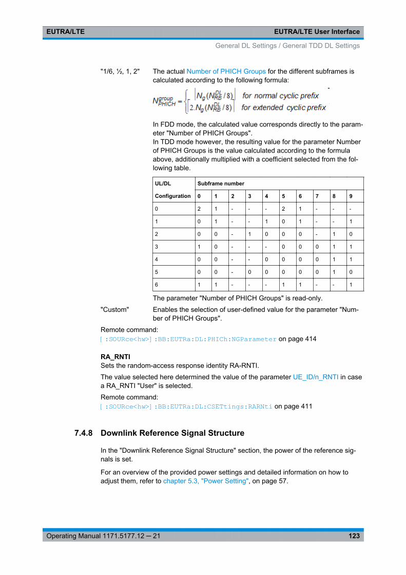
EUTRA/LTE User InterfaceEUTRA/LTE
123Operating Manual 1171.5177.12 ─ 21
"1/6, ½, 1, 2" The actual Number of PHICH Groups for the different subframes iscalculated according to the following formula:
In FDD mode, the calculated value corresponds directly to the param-eter "Number of PHICH Groups".In TDD mode however, the resulting value for the parameter Numberof PHICH Groups is the value calculated according to the formulaabove, additionally multiplied with a coefficient selected from the fol-lowing table.
UL/DL Subframe number
Configuration 0 1 2 3 4 5 6 7 8 9
0 2 1 - - - 2 1 - - -
1 0 1 - - 1 0 1 - - 1
2 0 0 - 1 0 0 0 - 1 0
3 1 0 - - - 0 0 0 1 1
4 0 0 - - 0 0 0 0 1 1
5 0 0 - 0 0 0 0 0 1 0
6 1 1 - - - 1 1 - - 1
The parameter "Number of PHICH Groups" is read-only.
"Custom" Enables the selection of user-defined value for the parameter "Num-ber of PHICH Groups".
Remote command: [:SOURce<hw>]: BB: EUTRa:DL: PHICh:NGParameter on page 414
RA_RNTISets the random-access response identity RA-RNTI.
The value selected here determined the value of the parameter UE_ID/n_RNTI in casea RA_RNTI "User" is selected.
Remote command: [:SOURce<hw>]: BB:EUTRa: DL:CSETtings: RARNti on page 411
7.4.8 Downlink Reference Signal Structure
In the "Downlink Reference Signal Structure" section, the power of the reference sig-nals is set.
For an overview of the provided power settings and detailed information on how toadjust them, refer to chapter 5.3, "Power Setting", on page 57.
General DL Settings / General TDD DL Settings
EUTRA/LTE User InterfaceEUTRA/LTE
124Operating Manual 1171.5177.12 ─ 21
Reference Signal PowerSets the power of the reference signal (PRS relative).
Remote command: [: SOURce<hw>]: BB:EUTRa: DL:REFSig: POWer on page 406
RS Power per RE relative to Level DisplayDisplays the power of the reference signal (RS) per resource element (RE) relative tothe power value, displayed in the Level display in the header of the instrument.
Note: The displayed value is actualized only if the EUTRA/LTE signal generation isenabled (State = On).If a MIMO configuration is enabled, the value of this parameter is equal for all anten-nas; this applies also for the antenna configured in the path B.
Remote command: [:SOURce<hw>]: BB:EUTRa: DL:REFSig: EPRE on page 406
7.4.9 Synchronization Signal Settings
In the "Synchronization Signal Settings" section, the power of the P-SYNC/S-SYNC isset.
P-/S-SYNC Tx AntennaDefines on which antenna port the P-/S-SYNC is transmitted.
The available values depend on the number of configured antennas.
Remote command: [:SOURce<hw>]: BB:EUTRa: DL:SYNC: TXANtenna on page 407
P-SYNC PowerSets the power of the P-SYNC allocations.
Remote command: [:SOURce<hw>]: BB:EUTRa: DL:SYNC: PPOWer on page 407
S-SYNC PowerSets the power of the S-SYNC allocations.
Remote command: [: SOURce<hw>]: BB:EUTRa: DL:SYNC: SPOWer on page 407
7.4.10 Positioning Reference Signal (PRS) Settings
Configuration of the PRSs requires additional SW option R&S SMx/AMU-K84.
1. To access this dialog select "General > Link Direction > Downlink (OFDMA)".
General DL Settings / General TDD DL Settings
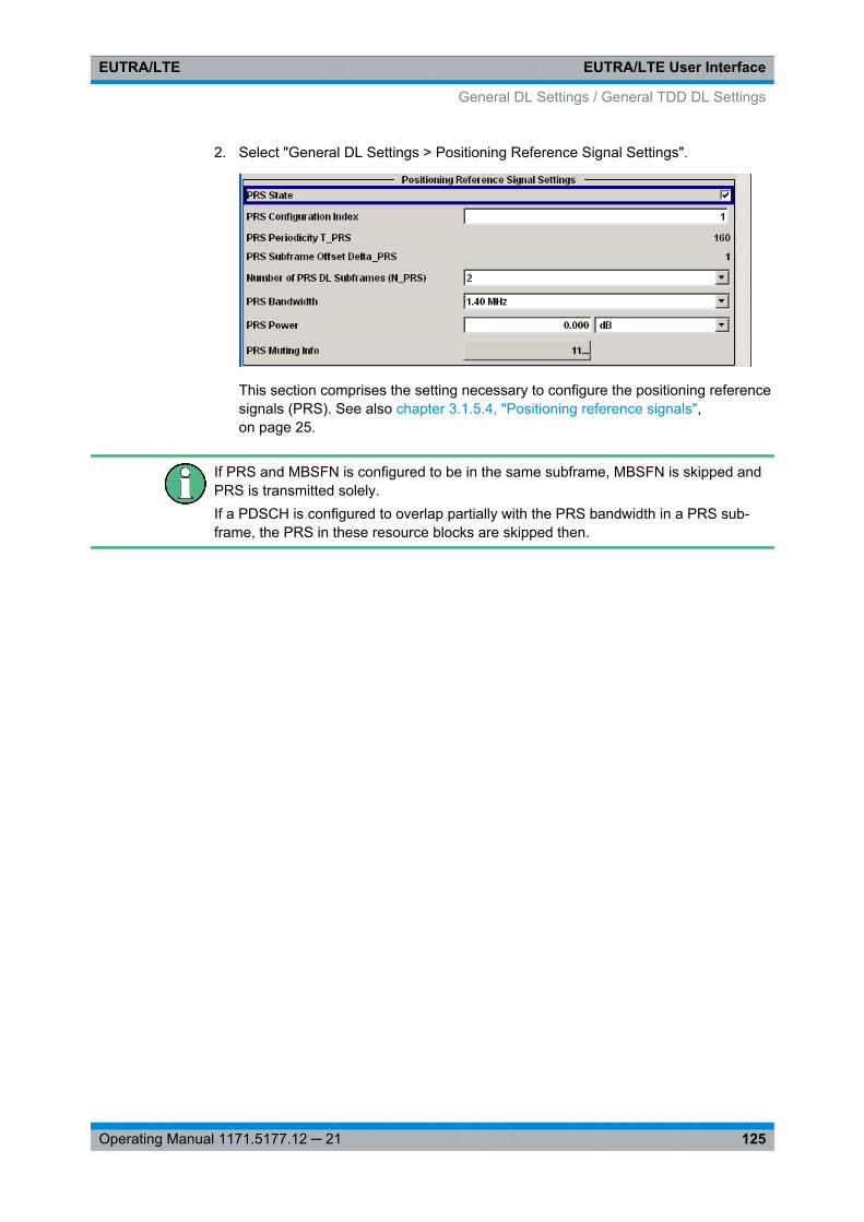
EUTRA/LTE User InterfaceEUTRA/LTE
125Operating Manual 1171.5177.12 ─ 21
2. Select "General DL Settings > Positioning Reference Signal Settings".
This section comprises the setting necessary to configure the positioning referencesignals (PRS). See also chapter 3.1.5.4, "Positioning reference signals",on page 25.
If PRS and MBSFN is configured to be in the same subframe, MBSFN is skipped andPRS is transmitted solely.If a PDSCH is configured to overlap partially with the PRS bandwidth in a PRS sub-frame, the PRS in these resource blocks are skipped then.
General DL Settings / General TDD DL Settings
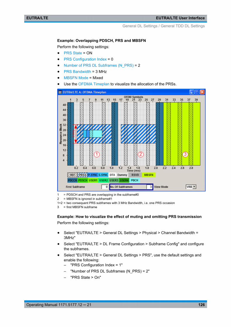
EUTRA/LTE User InterfaceEUTRA/LTE
126Operating Manual 1171.5177.12 ─ 21
Example: Overlapping PDSCH, PRS and MBSFNPerform the following settings:● PRS State = ON● PRS Configuration Index = 0● Number of PRS DL Subframes (N_PRS) = 2● PRS Bandwidth = 3 MHz● MBSFN Mode = Mixed● Use the OFDMA Timeplan to visualize the allocation of the PRSs.
1 = PDSCH and PRS are overlapping in the subframe#02 = MBSFN is ignored in subframe#11+2 = two consequent PRS subframes with 3 MHz Bandwidth, i.e. one PRS occasion3 = first MBSFN subframe
Example: How to visualize the effect of muting and omitting PRS transmissionPerform the following settings:
● Select "EUTRA/LTE > General DL Settings > Physical > Channel Bandwidth =3MHz"
● Select "EUTRA/LTE > DL Frame Configuration > Subframe Config" and configurethe subframes.
● Select "EUTRA/LTE > General DL Settings > PRS", use the default settings andenable the following:– "PRS Configuration Index = 1"– "Number of PRS DL Subframes (N_PRS) = 2"– "PRS State > On"
General DL Settings / General TDD DL Settings
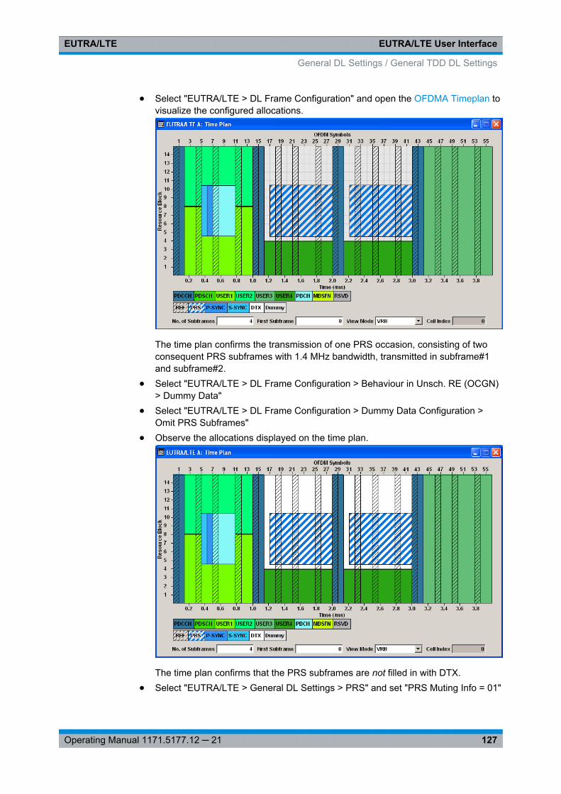
EUTRA/LTE User InterfaceEUTRA/LTE
127Operating Manual 1171.5177.12 ─ 21
● Select "EUTRA/LTE > DL Frame Configuration" and open the OFDMA Timeplan tovisualize the configured allocations.
The time plan confirms the transmission of one PRS occasion, consisting of twoconsequent PRS subframes with 1.4 MHz bandwidth, transmitted in subframe#1and subframe#2.
● Select "EUTRA/LTE > DL Frame Configuration > Behaviour in Unsch. RE (OCGN)> Dummy Data"
● Select "EUTRA/LTE > DL Frame Configuration > Dummy Data Configuration >Omit PRS Subframes"
● Observe the allocations displayed on the time plan.
The time plan confirms that the PRS subframes are not filled in with DTX.● Select "EUTRA/LTE > General DL Settings > PRS" and set "PRS Muting Info = 01"
General DL Settings / General TDD DL Settings
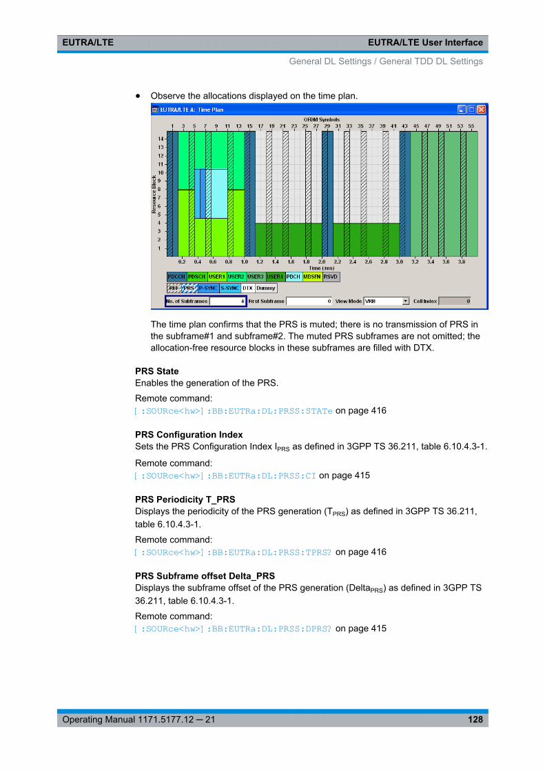
EUTRA/LTE User InterfaceEUTRA/LTE
128Operating Manual 1171.5177.12 ─ 21
● Observe the allocations displayed on the time plan.
The time plan confirms that the PRS is muted; there is no transmission of PRS inthe subframe#1 and subframe#2. The muted PRS subframes are not omitted; theallocation-free resource blocks in these subframes are filled with DTX.
PRS StateEnables the generation of the PRS.
Remote command: [:SOURce<hw>]: BB:EUTRa: DL:PRSS: STATe on page 416
PRS Configuration IndexSets the PRS Configuration Index IPRS as defined in 3GPP TS 36.211, table 6.10.4.3-1.
Remote command: [:SOURce<hw>]: BB:EUTRa: DL:PRSS: CI on page 415
PRS Periodicity T_PRSDisplays the periodicity of the PRS generation (TPRS) as defined in 3GPP TS 36.211,table 6.10.4.3-1.
Remote command: [: SOURce<hw>]: BB:EUTRa: DL:PRSS:TPRS? on page 416
PRS Subframe offset Delta_PRSDisplays the subframe offset of the PRS generation (DeltaPRS) as defined in 3GPP TS36.211, table 6.10.4.3-1.
Remote command: [:SOURce<hw>]: BB:EUTRa: DL:PRSS: DPRS? on page 415
General DL Settings / General TDD DL Settings
EUTRA/LTE User InterfaceEUTRA/LTE
129Operating Manual 1171.5177.12 ─ 21
Number of PRS DL Subframes (N_PRS)Defines the number of consecutive DL subframes in that PRS are transmitted. Severalconsecutive DL subframes build one PRS occasion.
Remote command: [:SOURce<hw>]: BB: EUTRa:DL: PRSS:NPRS on page 415
PRS BandwidthDefines the RBs in which the PRS is transmitted.
Note: The PRS Bandwidth must not be bigger than channel bandwidth.
Remote command: [:SOURce<hw>]: BB:EUTRa: DL:PRSS: BW on page 414
PRS PowerSets the power of a PRS resource element relative to the power of a common refer-ence signal resource element.
Remote command: [:SOURce<hw>]: BB:EUTRa: DL:PRSS: POW on page 415
PRS Muting InfoSpecifies a bit pattern that defines the muted and not muted PRS. The bit pattern canbe 2, 4, 8 or 16 bit long, where each bit defines the PRS state of one PRS occasion.The parameter Number of PRS DL Subframes (N_PRS) defines the length of the PRSoccasions.
See example "How to visualize the effect of muting and omitting PRS transmission"on page 126
"0" PRS is muted in the corresponfing PRS occasion.
"1" PRS is not muted, i.e. PRS is transmitted in the corresponfing PRSoccasion.
Remote command: [:SOURce<hw>]: BB: EUTRa:DL: PRSS:MIPattern on page 416
7.4.11 CSI Settings
To access this dialog:
1. Select "General > Link Direction > Downlink (OFDMA)".
2. Select "General DL Settings > CSI-RS Structure".
General DL Settings / General TDD DL Settings
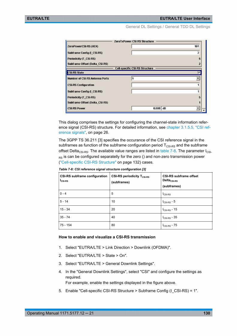
EUTRA/LTE User InterfaceEUTRA/LTE
130Operating Manual 1171.5177.12 ─ 21
This dialog comprises the settings for configuring the channel-state information refer-ence signal (CSI-RS) structure. For detailed information, see chapter 3.1.5.5, "CSI ref-erence signals", on page 26.
The 3GPP TS 36.211 [3] specifies the occurance of the CSI reference signal in thesubframes as function of the subframe configuration period TCSI-RS and the subframeoffset DeltaCSI-RS. The available value ranges are listed in table 7-8. The parameter ICSI-
RS is can be configured separatelly for the zero () and non-zero transmission power("Cell-specific CSI-RS Structure" on page 132) cases.
Table 7-8: CSI reference signal structure configuration [3]
CSI-RS subframe configurationICSI-RS
CSI-RS periodicity TCSI-RS
(subframes)
CSI-RS subframe offsetDeltaCSI-RS
(subframes)
0 - 4 5 ICSI-RS
5 - 14 10 ICSI-RS - 5
15 - 34 20 ICSI-RS - 15
35 - 74 40 ICSI-RS - 35
75 - 154 80 ICSI-RS - 75
How to enable and visualize a CSI-RS transmission
1. Select "EUTRA/LTE > Link Direction > Downlink (OFDMA)".
2. Select "EUTRA/LTE > State > On".
3. Select "EUTRA/LTE > General Downlink Settings".
4. In the "General Downlink Settings", select "CSI" and configure the settings asrequired.For example, enable the settings displayed in the figure above.
5. Enable "Cell-specific CSI-RS Structure > Subframe Config (I_CSI-RS) = 1".
General DL Settings / General TDD DL Settings
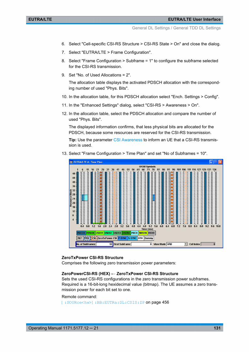
EUTRA/LTE User InterfaceEUTRA/LTE
131Operating Manual 1171.5177.12 ─ 21
6. Select "Cell-specific CSI-RS Structure > CSI-RS State > On" and close the dialog.
7. Select "EUTRA/LTE > Frame Configuration".
8. Select "Frame Configuration > Subframe = 1" to configure the subframe selectedfor the CSI-RS transmission.
9. Set "No. of Used Allocations = 2".
The allocation table displays the activated PDSCH allocation with the correspond-ing number of used "Phys. Bits".
10. In the allocation table, for this PDSCH allocation select "Ench. Settings > Config".
11. In the "Enhanced Settings" dialog, select "CSI-RS > Awareness > On".
12. In the allocation table, select the PDSCH allocation and compare the number ofused "Phys. Bits".
The displayed information confirms, that less physical bits are allocated for thePDSCH, because some resources are reserved for the CSI-RS transmission.
Tip: Use the parameter CSI Awareness to inform an UE that a CSI-RS transmis-sion is used.
13. Select "Frame Configuration > Time Plan" and set "No of Subframes = 10".
ZeroTxPower CSI-RS StructureComprises the following zero transmission power parameters:
ZeroPowerCSI-RS (HEX) ← ZeroTxPower CSI-RS StructureSets the used CSI-RS configurations in the zero transmission power subframes.Required is a 16-bit-long hexidecimal value (bitmap). The UE assumes a zero trans-mission power for each bit set to one.
Remote command: [:SOURce<hw>]: BB: EUTRa:DL:CSIS: ZP on page 456
General DL Settings / General TDD DL Settings
EUTRA/LTE User InterfaceEUTRA/LTE
132Operating Manual 1171.5177.12 ─ 21
Subframe Config (I_CSI-RS) ← ZeroTxPower CSI-RS StructureSets the parameter ICSI-RS for CSI-RS with zero transmission power, see table 7-8.
Remote command: [: SOURce<hw>]: BB:EUTRa: DL:CSIS:ZPI on page 456
Periodicity (T_CSI-RS) ← ZeroTxPower CSI-RS StructureSets the parameter subframe configuration period TCSI-RS for CSI-RS with zero trans-mission power, see table 7-8.
Remote command: [:SOURce<hw>]: BB:EUTRa: DL:CSIS: ZPT? on page 457
Subframe Offset (Delta_CSI-RS) ← ZeroTxPower CSI-RS StructureSets the parameter subframe offset DeltaCSI-RS for CSI-RS with zero transmissionpower, see table 7-8.
Remote command: [:SOURce<hw>]: BB:EUTRa: DL:CSIS: ZPDelta? on page 456
Cell-specific CSI-RS StructureComprises the following cell-specific parameters:
CSI-RS State ← Cell-specific CSI-RS StructureEnables the transmission of a CSI-RS, see also "How to enable and visualize a CSI-RS transmission" on page 130.
Remote command: [:SOURce<hw>]: BB: EUTRa:DL: CSIS:STATe on page 456
Number of CSI-RS Antenna Ports ← Cell-specific CSI-RS StructureDefines the number of antenna ports (one, two, four or eight) the CSI-RS are transmit-ted on.
Use the Cell Specific Antenna Port Mapping and configure the cell-specific antennaport mapping of the antenna ports AP15 - AP22.
Remote command: [:SOURce<hw>]: BB: EUTRa:DL: CSIS:NAP on page 454
CSI-RS Configuration ← Cell-specific CSI-RS StructureDefines the CSI-RS configuration used for the current cell and for wich the UEassumes non-zero transmission power. The zero transmission power sunframes aredetermined by the ZeroPowerCSI-RS (HEX).
Remote command: [:SOURce<hw>]: BB: EUTRa:DL:CSIS: CONFig on page 454
Subframe Config (I_CSI-RS) ← Cell-specific CSI-RS StructureSets the parameter ICSI-RS for cell-specific CSI-RS, see table 7-8.
Remote command: [: SOURce<hw>]: BB:EUTRa: DL:CSIS: SFI on page 455
General DL Settings / General TDD DL Settings

EUTRA/LTE User InterfaceEUTRA/LTE
133Operating Manual 1171.5177.12 ─ 21
Periodicity (T_CSI-RS) ← Cell-specific CSI-RS StructureSets the parameter subframe configuration period TCSI-RS for cell-specific CSI-RS, seetable 7-8.
Remote command: [:SOURce<hw>]: BB:EUTRa: DL:CSIS: SFT? on page 455
Subframe Offset (Delta_CSI-RS) ← Cell-specific CSI-RS StructureSets the parameter subframe offset DeltaCSI-RS for cell-specific CSI-RS, see table 7-8.
Remote command: [:SOURce<hw>]: BB:EUTRa: DL:CSIS: SFDelta? on page 455
CSI-RS Power ← Cell-specific CSI-RS StructureBoosts the CSI-RS power compared to the cell-specific reference signals.
Remote command: [: SOURce<hw>]: BB:EUTRa: DL:CSIS: POW on page 455
7.5 DL Frame Configuration Settings
To access this dialog:
1. Select "General > Link Direction > Downlink (OFDMA)".
2. Select "Frame Configuration".
The "DL Frame Configuration" dialog allows you to configure the subframes andthe OFDMA resource allocations. The dialog consists of several tabs.The "DL Frame Configuration" dialog consists of three sections, "General FrameConfiguration", "Subframe Configuration" and the "Allocation Table".
DL Frame Configuration Settings
EUTRA/LTE User InterfaceEUTRA/LTE
134Operating Manual 1171.5177.12 ─ 21
7.5.1 General Frame Configuration Settings
Provided are the following settings:
No Of Configurable (DL) SubframesSets the number of configurable subframes. Only the downlink and the special sub-frames are enabled for configuration if TDD mode is selected.
All downlink/special subframes are filled periodically with the configured subframeswith the exception of the P-SYNC/S-SYNC which are set globally in the "General DLSettings" menu and the PBCH which can only be configured in subframe 0.
For more detailed information about the maximum number of configurable subframesand for description of the dependencies between the parameters, see chapter 5.2.3,"Four Configurable Frames in Uplink and Downlink Direction", on page 54.
Remote command: [:SOURce<hw>]: BB: EUTRa:DL:CONSubframes on page 431
Reset Subframe ConfigurationResets settings of all subframes including cyclic prefix and number of used allocationsto the default values.
Remote command: [:SOURce<hw>]: BB: EUTRa:DL: RSTFrame on page 431
Configure UserCalls the "Configure User" menu for configuring allocations for different users.
The menu is described in chapter 7.8, "User Configuration Settings", on page 177.
Remote command: n.a.
Behavior In Unscheduled REs (OCNG)Selects either to fill unscheduled resource elements and subframes with dummy dataor DTX.
This function can be used as an OFDMA Channel Noise Generator (OCNG) accordingto 3GPP TS 36.101.
Remote command: [:SOURce<hw>]: BB:EUTRa: DL:BUR on page 431
Dummy Data Configuration(Available for Dummy Data only)
Access the "Dummy Data Configuration" dialog for setting the modulation, power anddata source for the dummy data.
The menu is described in chapter 7.11, "Dummy Data Configuration Settings",on page 190.
Remote command: n.a.
DL Frame Configuration Settings
EUTRA/LTE User InterfaceEUTRA/LTE
135Operating Manual 1171.5177.12 ─ 21
7.5.2 Subframe Configuration Settings
Provided are the following settings:
Subframe SelectionSets the subframe to be configured in the frame configuration table.
Remote command: [: SOURce<hw>]: BB:EUTRa: DL:SFSelection on page 431
Cyclic PrefixConfiguration of the cyclic prefix per subframe is only enabled, if the parameter CyclicPrefix is set to User Defined.
The number of the OFDM symbols per subframe is set automatically.
Remote command: [:SOURce<hw>]: BB: EUTRa:DL[: SUBF<st0>]: CYCPrefix on page 432
No. Of Used AllocationsSets the number of scheduled allocations in the selected subframe.
The number of available allocations depends on the allocation's content type for a sub-frame and the general channel bandwidth setting.
The default value depends on the existence of a PBCH channel in a subframe. In thiscase the default value is set to 2, otherwise to 1; the second respectively the first allo-cation is reserved for the PDCCH, regardless whether this allocation is enabled or not.
Remote command: [:SOURce<hw>]: BB: EUTRa:DL[: SUBF<st0>]: ALCount on page 432
Copy/PasteCopies/pastes the settings of the selected subframe. P-SYNC/S-SYNC/PBCH settingsare not considered.
For more detailed information, see chapter 5.2.1, "Copy/Paste Subframe", on page 53.
Remote command: n.a.
Show Time PlanCalls the time plan for the OFDMA resource allocation.
The menu is described in detail in chapter 7.12, "OFDMA Timeplan", on page 192.
Remote command: n.a.
Configure PCFICH, PHICH, PDCCHCalls a dialog for configuring the PCFICH, PHICH and PDCCH.
The dialog is described in detail in chapter 7.7, "Enhanced PCFICH, PHICH andPDCCH Channel Configuration", on page 152.
Remote command: n.a.
DL Frame Configuration Settings
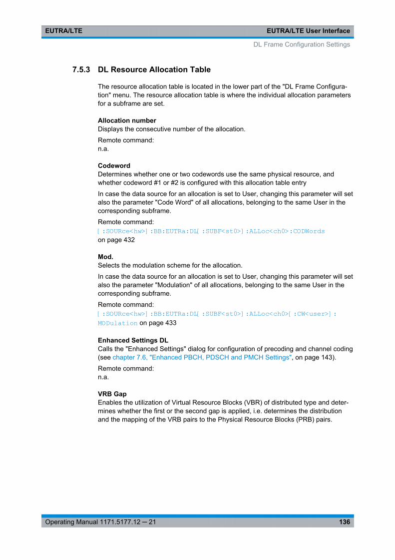
EUTRA/LTE User InterfaceEUTRA/LTE
136Operating Manual 1171.5177.12 ─ 21
7.5.3 DL Resource Allocation Table
The resource allocation table is located in the lower part of the "DL Frame Configura-tion" menu. The resource allocation table is where the individual allocation parametersfor a subframe are set.
Allocation numberDisplays the consecutive number of the allocation.
Remote command: n.a.
CodewordDetermines whether one or two codewords use the same physical resource, andwhether codeword #1 or #2 is configured with this allocation table entry
In case the data source for an allocation is set to User, changing this parameter will setalso the parameter "Code Word" of all allocations, belonging to the same User in thecorresponding subframe.
Remote command: [: SOURce<hw>]: BB:EUTRa: DL[:SUBF<st0>]: ALLoc<ch0>: CODWords on page 432
Mod.Selects the modulation scheme for the allocation.
In case the data source for an allocation is set to User, changing this parameter will setalso the parameter "Modulation" of all allocations, belonging to the same User in thecorresponding subframe.
Remote command: [:SOURce<hw>]: BB: EUTRa:DL[: SUBF<st0>]: ALLoc<ch0>[: CW<user>]: MODulation on page 433
Enhanced Settings DLCalls the "Enhanced Settings" dialog for configuration of precoding and channel coding(see chapter 7.6, "Enhanced PBCH, PDSCH and PMCH Settings", on page 143).
Remote command: n.a.
VRB GapEnables the utilization of Virtual Resource Blocks (VBR) of distributed type and deter-mines whether the first or the second gap is applied, i.e. determines the distributionand the mapping of the VRB pairs to the Physical Resource Blocks (PRB) pairs.
DL Frame Configuration Settings
EUTRA/LTE User InterfaceEUTRA/LTE
137Operating Manual 1171.5177.12 ─ 21
The VRB-to-PRB mapping and the calculation of the VRB gap values are performedaccording to 3GPP TS 36.211. The specification defines two types of VRBs, a local-ized distribution with a direct mapping and distributed VRBs for better frequency diver-sity. The distribution of the VRBs is performed in such a way, that consecutive VRBsare not mapped to frequency-consecutive PRBs, i.e. the VRBs are spread over the fre-quencies. Each single VRB pair is split into two parts and a frequency gap betweenthese two VRB parts is introduced, i.e. a frequency hopping on a slot basis is applied.For wider channel bandwidths (more than 50 RBs), a second VRB gap with smallersize may be applied.
Tip: Use the "DL Time Plan" to visualize the PDSCH mapping.
The information whether localizated or distributed VBRs are applied is carried by thePDCCH. The DCI Formats 1A/1B/1D provide the special 1-bit flag "Localized/Distrib-uted VBR Assignment" for this purpose. The selection whether the first or the secondgap is applied, is determined by the additional bit "Gap Value".
Note: In case a Auto DCI mode is used, the "VRB Gap" value is read-only and is setaccording to the configuration of the corresponding DCI format.
DL Frame Configuration Settings
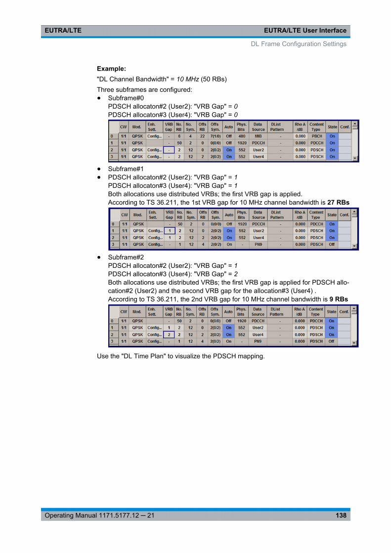
EUTRA/LTE User InterfaceEUTRA/LTE
138Operating Manual 1171.5177.12 ─ 21
Example: "DL Channel Bandwidth" = 10 MHz (50 RBs)Three subframes are configured:● Subframe#0
PDSCH allocaton#2 (User2): "VRB Gap" = 0PDSCH allocaton#3 (User4): "VRB Gap" = 0
● Subframe#1● PDSCH allocaton#2 (User2): "VRB Gap" = 1
PDSCH allocaton#3 (User4): "VRB Gap" = 1Both allocations use distributed VRBs; the first VRB gap is applied.According to TS 36.211, the 1st VRB gap for 10 MHz channel bandwidth is 27 RBs
● Subframe#2PDSCH allocaton#2 (User2): "VRB Gap" = 1PDSCH allocaton#3 (User4): "VRB Gap" = 2Both allocations use distributed VRBs; the first VRB gap is applied for PDSCH allo-cation#2 (User2) and the second VRB gap for the allocation#3 (User4) .According to TS 36.211, the 2nd VRB gap for 10 MHz channel bandwidth is 9 RBs
Use the "DL Time Plan" to visualize the PDSCH mapping.
DL Frame Configuration Settings
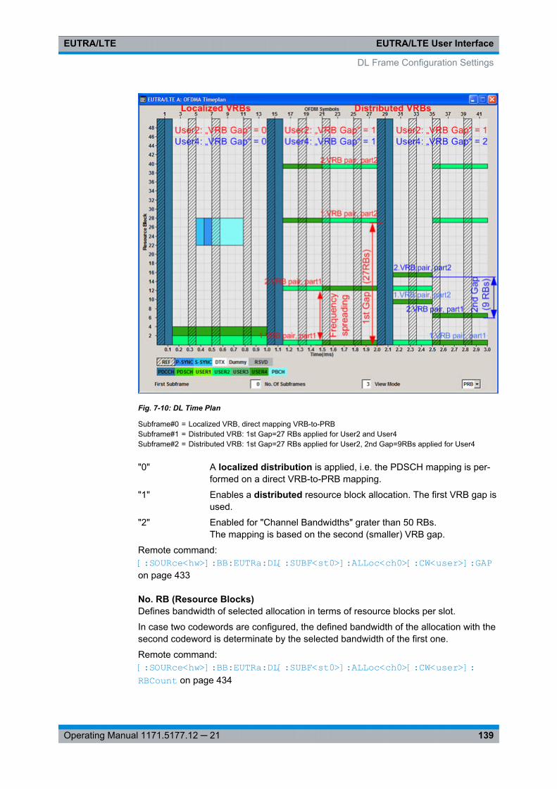
EUTRA/LTE User InterfaceEUTRA/LTE
139Operating Manual 1171.5177.12 ─ 21
Fig. 7-10: DL Time Plan
Subframe#0 = Localized VRB, direct mapping VRB-to-PRBSubframe#1 = Distributed VRB: 1st Gap=27 RBs applied for User2 and User4Subframe#2 = Distributed VRB: 1st Gap=27 RBs applied for User2, 2nd Gap=9RBs applied for User4
"0" A localized distribution is applied, i.e. the PDSCH mapping is per-formed on a direct VRB-to-PRB mapping.
"1" Enables a distributed resource block allocation. The first VRB gap isused.
"2" Enabled for "Channel Bandwidths" grater than 50 RBs.The mapping is based on the second (smaller) VRB gap.
Remote command: [:SOURce<hw>]: BB: EUTRa:DL[: SUBF<st0>]: ALLoc<ch0>[: CW<user>]: GAPon page 433
No. RB (Resource Blocks)Defines bandwidth of selected allocation in terms of resource blocks per slot.
In case two codewords are configured, the defined bandwidth of the allocation with thesecond codeword is determinate by the selected bandwidth of the first one.
Remote command: [: SOURce<hw>]: BB:EUTRa: DL[:SUBF<st0>]: ALLoc<ch0>[: CW<user>]: RBCount on page 434
DL Frame Configuration Settings
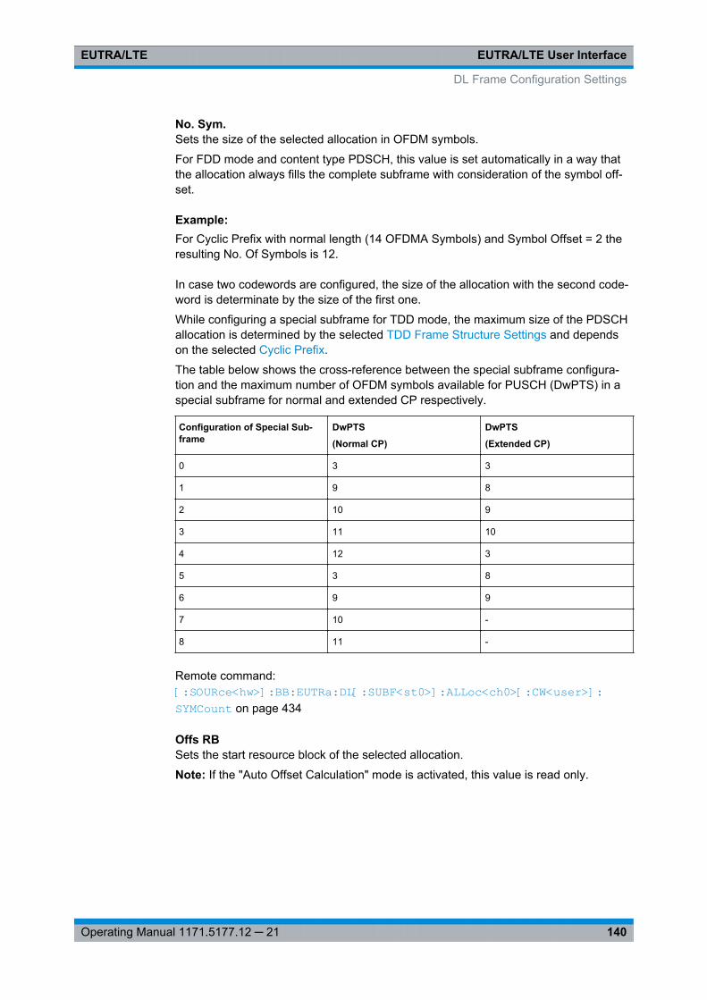
EUTRA/LTE User InterfaceEUTRA/LTE
140Operating Manual 1171.5177.12 ─ 21
No. Sym.Sets the size of the selected allocation in OFDM symbols.
For FDD mode and content type PDSCH, this value is set automatically in a way thatthe allocation always fills the complete subframe with consideration of the symbol off-set.
Example: For Cyclic Prefix with normal length (14 OFDMA Symbols) and Symbol Offset = 2 theresulting No. Of Symbols is 12.
In case two codewords are configured, the size of the allocation with the second code-word is determinate by the size of the first one.
While configuring a special subframe for TDD mode, the maximum size of the PDSCHallocation is determined by the selected TDD Frame Structure Settings and dependson the selected Cyclic Prefix.
The table below shows the cross-reference between the special subframe configura-tion and the maximum number of OFDM symbols available for PUSCH (DwPTS) in aspecial subframe for normal and extended CP respectively.
Configuration of Special Sub-frame
DwPTS
(Normal CP)
DwPTS
(Extended CP)
0 3 3
1 9 8
2 10 9
3 11 10
4 12 3
5 3 8
6 9 9
7 10 -
8 11 -
Remote command: [:SOURce<hw>]: BB: EUTRa:DL[: SUBF<st0>]: ALLoc<ch0>[: CW<user>]: SYMCount on page 434
Offs RBSets the start resource block of the selected allocation.
Note: If the "Auto Offset Calculation" mode is activated, this value is read only.
DL Frame Configuration Settings
EUTRA/LTE User InterfaceEUTRA/LTE
141Operating Manual 1171.5177.12 ─ 21
In case two codewords are configured, the start resource block of the allocation withthe second codeword is determinate by the selected start resource block of the firstone.
Remote command: [:SOURce<hw>]: BB:EUTRa: DL[:SUBF<st0>]: ALLoc<ch0>[: CW<user>]: RBOFfset on page 435
Offs Sym.Sets the start OFDM symbol of the selected allocation.
Note: If the "Auto Offset Calculation" mode is activated, this value is read only.For extended cyclic prefix, the maximum symbol offset is 13.
Note: According to 3GPP TS 36.211, up to first three OFDM symbols of a subframeare reserved for control information (PDCCH). Therefore, for PDSCH allocations themaximum value is 3, regardless of the cyclic prefix length.In case two codewords are configured, the start OFDM symbol of the allocation withthe second codeword is determinate by the selected start OFDM symbol of the firstone.
Remote command: [:SOURce<hw>]: BB:EUTRa: DL[:SUBF<st0>]: ALLoc<ch0>[: CW<user>]: SYMoffset on page 435
AutoSets whether automatic offset calculation is used or not.
Note: If the "Auto Offset Calculation" mode is activated, the resource block offset andthe start symbol offset are set automatically and cannot be changed.By setting new allocations or changing the number of RBs of an existing allocation, theAuto mode tries to distribute the allocations with activated Auto mode in an optimalmanner to the available resource blocks by adjusting the parameters "Offset RB". Theresulting "No. of Bits" of a certain allocation can vary, due to overlapping control chan-nels.
If it is not possible to distribute the changed configuration to the available resourcesblocks, a conflict is displayed.
Note: "Auto Offset Calculation" mode is only available for PDSCH. For PDCCH thisparameter is always off.In case two codewords are configured, the state of the "Auto Offset Calculation" modeof the second codeword is set to the state of the first one.
Remote command: [:SOURce<hw>]: BB:EUTRa: DL[:SUBF<st0>]: ALLoc<ch0>[: CW<user>]: AOCon page 436
DL Frame Configuration Settings
EUTRA/LTE User InterfaceEUTRA/LTE
142Operating Manual 1171.5177.12 ─ 21
Phys. BitsDisplays the size of the selected allocation in bits and considering the subcarriers thatare used for other signals or channels with higher priority (see chapter 5.1, "ConflictHandling", on page 49 ).
Remote command: [:SOURce<hw>]: BB:EUTRa: DL[:SUBF<st0>]: ALLoc<ch0>[: CW<user>]: PHYSbits? on page 436
Data SourceSelects the data source for the selected allocation.
For PBCH allocation with enabled parameter MIB (including SFN), the "Data Source" isset to "MIB".
Use the User Configuration Settings dialog to configure the data sources for "User 1 ..4".
The following standard data sources are available:● "All 0, All 1"
An internally generated sequence containing 0 data or 1 data.● "PNxx"
An internally generated pseudo-random noise sequence.● "Pattern"
An internally generated sequence according to a bit pattern.Use the "Pattern" box to define the bit pattern.
● "Data List/Select DList"A binary data from a data list, internally or externally generated.Select "Select DList" to access the standard "Select List" dialog.– Select the "Select Data List > navigate to the list file *.dm_iqd > Select" to
select an existing data list.– Use the "New" and "Edit" functions to create internally new data list or to edit
an existing one.– Use the standard "File Manager" function to transfer external data lists to the
instrument.See also "Main Dialog > Data List Management".
Remote command: [:SOURce<hw>]: BB:EUTRa:DL[: SUBF<st0>]: ALLoc<ch0>[: CW<user>]: DATAon page 437[:SOURce<hw>]: BB:EUTRa:DL[: SUBF<st0>]: ALLoc<ch0>[: CW<user>]: DSELect on page 437[:SOURce<hw>]: BB:EUTRa:DL[: SUBF<st0>]: ALLoc<ch0>[: CW<user>]: PATTern on page 437
Rho ASets the power PPDSCH respectively PPBCH for the selected allocation.
DL Frame Configuration Settings
EUTRA/LTE User InterfaceEUTRA/LTE
143Operating Manual 1171.5177.12 ─ 21
The power of the PDCCH allocation PPDCCH is read-only. The value is set in the"Enhanced Channel Configuration" dialog of the corresponding subframe.
Remote command: [: SOURce<hw>]: BB:EUTRa: DL[:SUBF<st0>]: ALLoc<ch0>[: CW<user>]: POWer on page 438
Content TypeSelects the type of the selected allocation.
Note: There can be only one PBCH in subframe 0.The reserved channel (RSVD) can be used for simulating possible upcoming channeltypes.
Remote command: [:SOURce<hw>]: BB:EUTRa: DL[:SUBF<st0>]: ALLoc<ch0>[: CW<user>]: CONType on page 438
StateSets the allocation to active or inactive state.
In case two codewords are configured, the state of the allocation with the second code-word is determinate by the state of the first one.
Remote command: [: SOURce<hw>]: BB:EUTRa: DL[:SUBF<st0>]: ALLoc<ch0>[: CW<user>]: STATe on page 439
ConflictIndicates a conflict between allocations.
For more information, see chapter 5.1, "Conflict Handling", on page 49.
Remote command: [:SOURce<hw>]: BB:EUTRa: DL[:SUBF<st0>]: ALLoc<ch0>[: CW<user>]: CONFlict on page 439
7.6 Enhanced PBCH, PDSCH and PMCH Settings
1. To access this dialog, select "General > Link Direction > Downlink (OFDMA)".
2. Select "Frame Configuration > Subframe Configuration > No of Used Allocations =3".
3. Select "Allocation Table > Allocation#3 > Content Type".
4. Select one of the following "Content Type"
a) "PBCH"b) "PDSCH"c) "PMCH"
Enhanced PBCH, PDSCH and PMCH Settings
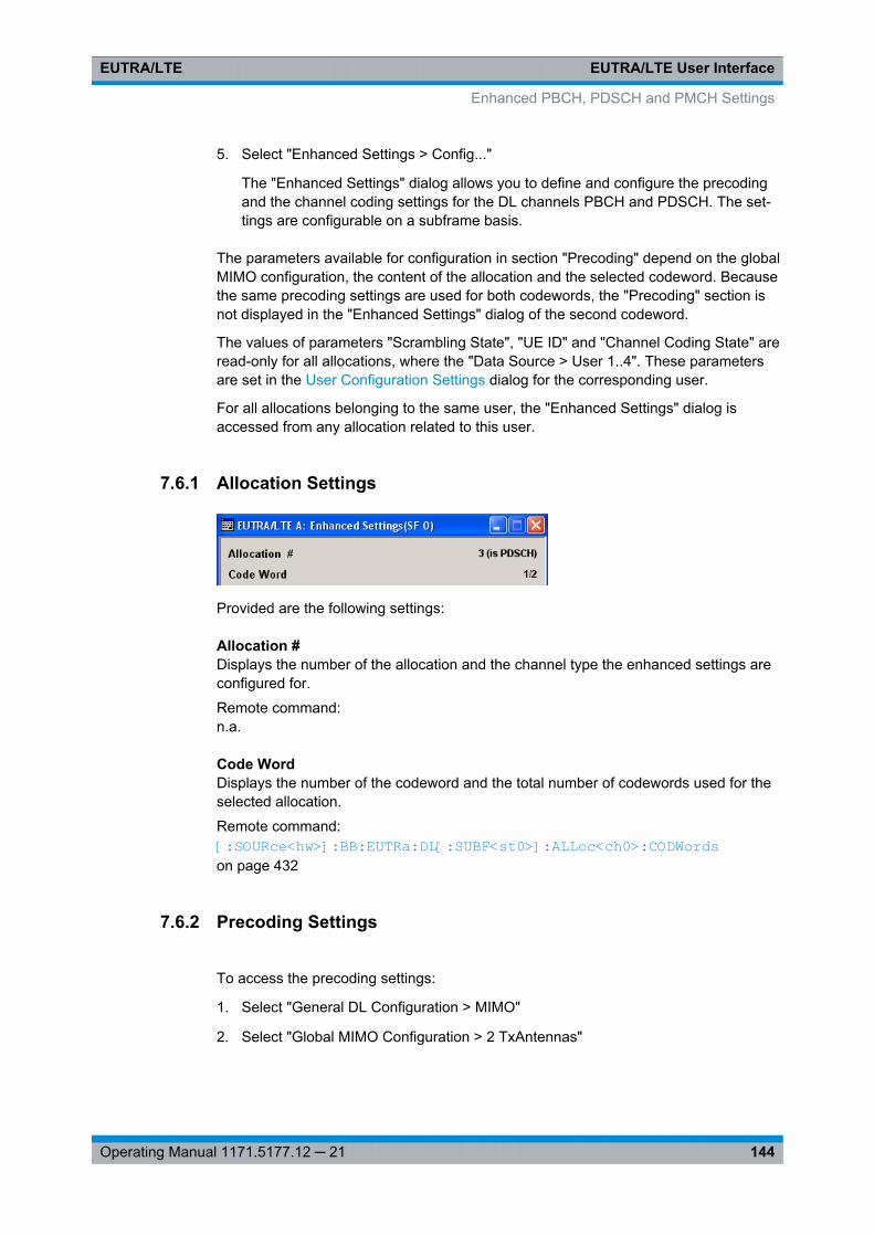
EUTRA/LTE User InterfaceEUTRA/LTE
144Operating Manual 1171.5177.12 ─ 21
5. Select "Enhanced Settings > Config..."
The "Enhanced Settings" dialog allows you to define and configure the precodingand the channel coding settings for the DL channels PBCH and PDSCH. The set-tings are configurable on a subframe basis.
The parameters available for configuration in section "Precoding" depend on the globalMIMO configuration, the content of the allocation and the selected codeword. Becausethe same precoding settings are used for both codewords, the "Precoding" section isnot displayed in the "Enhanced Settings" dialog of the second codeword.
The values of parameters "Scrambling State", "UE ID" and "Channel Coding State" areread-only for all allocations, where the "Data Source > User 1..4". These parametersare set in the User Configuration Settings dialog for the corresponding user.
For all allocations belonging to the same user, the "Enhanced Settings" dialog isaccessed from any allocation related to this user.
7.6.1 Allocation Settings
Provided are the following settings:
Allocation #Displays the number of the allocation and the channel type the enhanced settings areconfigured for.
Remote command: n.a.
Code WordDisplays the number of the codeword and the total number of codewords used for theselected allocation.
Remote command: [:SOURce<hw>]: BB: EUTRa:DL[: SUBF<st0>]: ALLoc<ch0>: CODWords on page 432
7.6.2 Precoding Settings
To access the precoding settings:
1. Select "General DL Configuration > MIMO"
2. Select "Global MIMO Configuration > 2 TxAntennas"
Enhanced PBCH, PDSCH and PMCH Settings
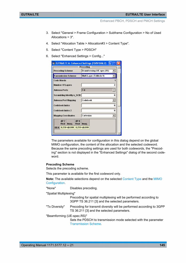
EUTRA/LTE User InterfaceEUTRA/LTE
145Operating Manual 1171.5177.12 ─ 21
3. Select "General > Frame Configuration > Subframe Configuration > No of UsedAllocations = 3".
4. Select "Allocation Table > Allocation#3 > Content Type".
5. Select "Content Type > PDSCH"
6. Select "Enhanced Settings > Config..."
The parameters available for configuration in this dialog depend on the globalMIMO configuration, the content of the allocation and the selected codeword.Because the same precoding settings are used for both codewords, the "Precod-ing" section is not displayed in the "Enhanced Settings" dialog of the second code-word.
Precoding SchemeSelects the precoding scheme.
This parameter is available for the first codeword only.
Note: The available selections depend on the selected Content Type and the MIMOConfiguration.
"None" Disables precoding.
"Spatial Multiplexing"Precoding for spatial multiplexing will be performed according to3GPP TS 36.211 [3] and the selected parameters.
"Tx Diversity" Precoding for transmit diversity will be performed according to 3GPPTS 36.211 [3] and the selected parameters.
"Beamforming (UE-spec.RS)"Sets the PDSCH to transmission mode selected with the parameterTransmission Scheme.
Enhanced PBCH, PDSCH and PMCH Settings
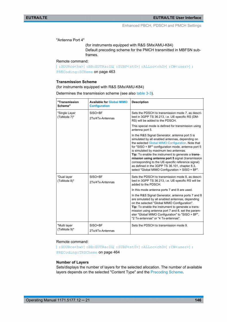
EUTRA/LTE User InterfaceEUTRA/LTE
146Operating Manual 1171.5177.12 ─ 21
"Antenna Port 4"(for instruments equipped with R&S SMx/AMU-K84)Default precoding scheme for the PMCH transmitted in MBFSN sub-frames.
Remote command: [:SOURce<hw>]: BB: EUTRa:DL[: SUBF<st0>]: ALLoc<ch0>[: CW<user>]: PRECoding: SCHeme on page 463
Transmission Scheme(for instruments equipped with R&S SMx/AMU-K84)
Determines the transmission scheme (see also table 3-3).
"TransmissionScheme"
Available for Global MIMOConfiguration
Description
"Single Layer(TxMode 7)"
SISO+BF
2Tx/4Tx-Antennas
Sets the PDSCH to transmission mode 7, as descri-bed in 3GPP TS 36.213, i.e. UE-specific RS (DM-RS) will be added to the PDSCH.
This special mode is defined for transmission usingantenna port 5.
In the R&S Signal Generator, antenna port 5 issimulated by all enabled antennas, depending onthe selected Global MIMO Configuration. Note thatfor "SISO + BF" configuration mode, antenna port 5is simulated by maximum two antennas.Tip: To enable the instrument to generate a trans-mission using antenna port 5 signal (transmissioncorresponding to the UE-specific reference signal)as defined in the 3GPP TS 36.101, chapter 8.3,select "Global MIMO Configuration > SISO + BF".
"Dual layer(TxMode 8)"
SISO+BF
2Tx/4Tx-Antennas
Sets the PDSCH to transmission mode 8, as descri-bed in 3GPP TS 36.213, i.e. UE-specific RS will beadded to the PDSCH.
In this mode antenna ports 7 and 8 are used.
In the R&S Signal Generator, antenna ports 7 and 8are simulated by all enabled antennas, dependingon the selected "Global MIMO Configuration".Tip: To enable the instrument to generate a trans-mission using antenna port 7 and 8, set the param-eter "Global MIMO Configuration" to "SISO + BF","2 Tx-antennas" or "4 Tx-antennas".
"Multi layer(TxMode 9)"
SISO+BF
2Tx/4Tx-Antennas
Sets the PDSCH to transmission mode 9.
Remote command: [:SOURce<hw>]: BB: EUTRa:DL[: SUBF<st0>]: ALLoc<ch0>[: CW<user>]: PRECoding: TRSCheme on page 464
Number of LayersSets/displays the number of layers for the selected allocation. The number of availablelayers depends on the selected "Content Type" and the Precoding Scheme.
Enhanced PBCH, PDSCH and PMCH Settings
EUTRA/LTE User InterfaceEUTRA/LTE
147Operating Manual 1171.5177.12 ─ 21
The combination of number of code words and number of layers determines the layermapping for the selected precoding scheme.
Remote command: [:SOURce<hw>]: BB:EUTRa: DL[:SUBF<st0>]: ALLoc<ch0>[: CW<user>]: PRECoding: NOLayers on page 463
Scrambling Identity n_SCIDSets the scrambling identity according to 36.211, sec. 6.10.3.1.
This value is used for initialization of the sequence used for generation of the UE-spe-cific reference signals.
Remote command: [:SOURce<hw>]: BB:EUTRa: DL[:SUBF<st0>]: ALLoc<ch0>[: CW<user>]: PRECoding: SCID on page 464
Antenna Ports(for instruments equipped with R&S SMx/AMU-K84)
Displays and configures the antenna port(s) for the selected Transmission Scheme.
In case only one code word and therefore only one layer is configured in the "DualLayer (TxMode 8)", the mapping of the layer to antenna port 7 or antenna port 8 is con-figurable.
Tip: Use this configuration possibility to configure a dual-layer multi-user MIMO (MU-MIMO) scenario.
Remote command: [:SOURce<hw>]: BB:EUTRa: DL[:SUBF<st0>]: ALLoc<ch0>[: CW<user>]: PRECoding: AP on page 461
Antenna Port Mapping(for instruments equipped with R&S SMx/AMU-K84)
Sets the way that the logical antenna ports are mapped to the physical Tx antennas,see chapter 7.9, "Antenna Port Mapping Settings", on page 181.
Remote command: [:SOURce<hw>]: BB:EUTRa: DL[:SUBF<st0>]: ALLoc<ch0>[: CW<user>]: PRECoding: APM on page 461
Codebook Index/Codebook Index 2(Enabled for Precoding Scheme set to Tx Diversity or Spatial Multiplexing and code-word 1 only)
Sets the codebook index for the selected allocation, i.e. selects the predefined pre-coder matrix.
The number of available codebook indices depends on the Global MIMO Configura-tion, i.e. the number of used antennas.
The figure bellow shows the range of the Codebook Index for Spatial Multiplexing.
Enhanced PBCH, PDSCH and PMCH Settings
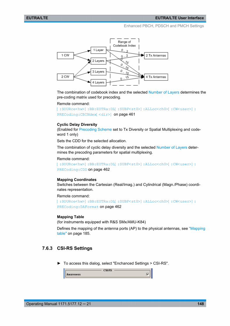
EUTRA/LTE User InterfaceEUTRA/LTE
148Operating Manual 1171.5177.12 ─ 21
The combination of codebook index and the selected Number of Layers determines thepre-coding matrix used for precoding.
Remote command: [:SOURce<hw>]: BB: EUTRa:DL[: SUBF<st0>]: ALLoc<ch0>[: CW<user>]: PRECoding: CBINdex[<dir>] on page 461
Cyclic Delay Diversity(Enabled for Precoding Scheme set to Tx Diversity or Spatial Multiplexing and code-word 1 only)
Sets the CDD for the selected allocation.
The combination of cyclic delay diversity and the selected Number of Layers deter-mines the precoding parameters for spatial multiplexing.
Remote command: [:SOURce<hw>]: BB: EUTRa:DL[: SUBF<st0>]: ALLoc<ch0>[: CW<user>]: PRECoding: CDD on page 462
Mapping CoordinatesSwitches between the Cartesian (Real/Imag.) and Cylindrical (Magn./Phase) coordi-nates representation.
Remote command: [:SOURce<hw>]: BB:EUTRa: DL[:SUBF<st0>]: ALLoc<ch0>[: CW<user>]: PRECoding: DAFormat on page 462
Mapping Table(for instruments equipped with R&S SMx/AMU-K84)
Defines the mapping of the antenna ports (AP) to the physical antennas, see "Mappingtable" on page 185.
7.6.3 CSI-RS Settings
► To access this dialog, select "Enchanced Settings > CSI-RS".
Enhanced PBCH, PDSCH and PMCH Settings
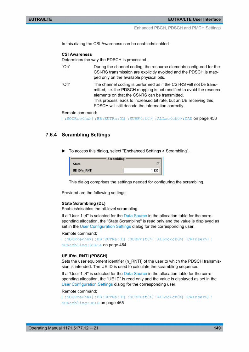
EUTRA/LTE User InterfaceEUTRA/LTE
149Operating Manual 1171.5177.12 ─ 21
In this dialog the CSI Awareness can be enabled/disabled.
CSI AwarenessDetermines the way the PDSCH is processed.
"On" During the channel coding, the resource elements configured for theCSI-RS transmission are explicitly avoided and the PDSCH is map-ped only on the available physical bits.
"Off" The channel coding is performed as if the CSI-RS will not be trans-mitted, i.e. the PDSCH mapping is not modified to avoid the resourceelements on that the CSI-RS can be transmitted.This process leads to increased bit rate, but an UE receiving thisPDSCH will still decode the information correctly.
Remote command: [:SOURce<hw>]: BB: EUTRa:DL[: SUBF<st0>]: ALLoc<ch0>: CAW on page 458
7.6.4 Scrambling Settings
► To access this dialog, select "Enchanced Settings > Scrambling".
This dialog comprises the settings needed for configuring the scrambling.
Provided are the following settings:
State Scrambling (DL)Enables/disables the bit-level scrambling.
If a "User 1..4" is selected for the Data Source in the allocation table for the corre-sponding allocation, the "State Scrambling" is read only and the value is displayed asset in the User Configuration Settings dialog for the corresponding user.
Remote command: [:SOURce<hw>]: BB:EUTRa:DL[: SUBF<st0>]: ALLoc<ch0>[: CW<user>]: SCRambling: STATe on page 464
UE ID/n_RNTI (PDSCH)Sets the user equipment identifier (n_RNTI) of the user to which the PDSCH transmis-sion is intended. The UE ID is used to calculate the scrambling sequence.
If a "User 1..4" is selected for the Data Source in the allocation table for the corre-sponding allocation, the "UE ID" is read only and the value is displayed as set in theUser Configuration Settings dialog for the corresponding user.
Remote command: [:SOURce<hw>]: BB: EUTRa:DL[: SUBF<st0>]: ALLoc<ch0>[: CW<user>]: SCRambling: UEID on page 465
Enhanced PBCH, PDSCH and PMCH Settings
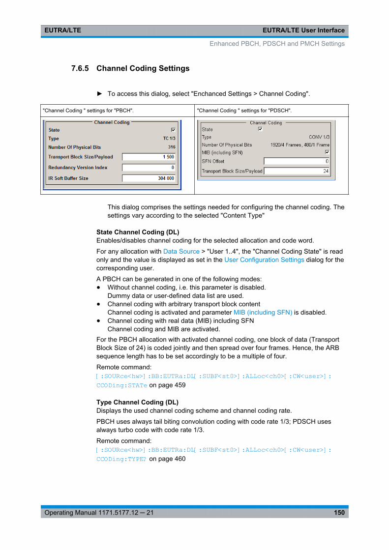
EUTRA/LTE User InterfaceEUTRA/LTE
150Operating Manual 1171.5177.12 ─ 21
7.6.5 Channel Coding Settings
► To access this dialog, select "Enchanced Settings > Channel Coding".
"Channel Coding " settings for "PBCH". "Channel Coding " settings for "PDSCH".
This dialog comprises the settings needed for configuring the channel coding. Thesettings vary according to the selected "Content Type"
State Channel Coding (DL)Enables/disables channel coding for the selected allocation and code word.
For any allocation with Data Source > "User 1..4", the "Channel Coding State" is readonly and the value is displayed as set in the User Configuration Settings dialog for thecorresponding user.
A PBCH can be generated in one of the following modes:● Without channel coding, i.e. this parameter is disabled.
Dummy data or user-defined data list are used.● Channel coding with arbitrary transport block content
Channel coding is activated and parameter MIB (including SFN) is disabled.● Channel coding with real data (MIB) including SFN
Channel coding and MIB are activated.For the PBCH allocation with activated channel coding, one block of data (TransportBlock Size of 24) is coded jointly and then spread over four frames. Hence, the ARBsequence length has to be set accordingly to be a multiple of four.
Remote command: [:SOURce<hw>]: BB: EUTRa:DL[: SUBF<st0>]: ALLoc<ch0>[: CW<user>]: CCODing: STATe on page 459
Type Channel Coding (DL)Displays the used channel coding scheme and channel coding rate.
PBCH uses always tail biting convolution coding with code rate 1/3; PDSCH usesalways turbo code with code rate 1/3.
Remote command: [:SOURce<hw>]: BB:EUTRa: DL[:SUBF<st0>]: ALLoc<ch0>[: CW<user>]: CCODing: TYPE? on page 460
Enhanced PBCH, PDSCH and PMCH Settings
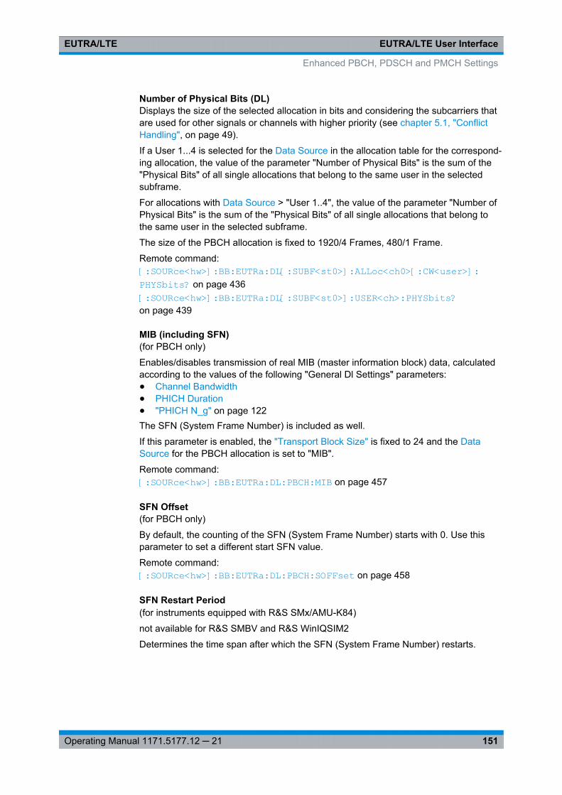
EUTRA/LTE User InterfaceEUTRA/LTE
151Operating Manual 1171.5177.12 ─ 21
Number of Physical Bits (DL)Displays the size of the selected allocation in bits and considering the subcarriers thatare used for other signals or channels with higher priority (see chapter 5.1, "ConflictHandling", on page 49).
If a User 1...4 is selected for the Data Source in the allocation table for the correspond-ing allocation, the value of the parameter "Number of Physical Bits" is the sum of the"Physical Bits" of all single allocations that belong to the same user in the selectedsubframe.
For allocations with Data Source > "User 1..4", the value of the parameter "Number ofPhysical Bits" is the sum of the "Physical Bits" of all single allocations that belong tothe same user in the selected subframe.
The size of the PBCH allocation is fixed to 1920/4 Frames, 480/1 Frame.
Remote command: [:SOURce<hw>]: BB:EUTRa: DL[:SUBF<st0>]: ALLoc<ch0>[: CW<user>]: PHYSbits? on page 436[:SOURce<hw>]: BB:EUTRa: DL[:SUBF<st0>]: USER<ch>: PHYSbits? on page 439
MIB (including SFN)(for PBCH only)
Enables/disables transmission of real MIB (master information block) data, calculatedaccording to the values of the following "General Dl Settings" parameters:● Channel Bandwidth● PHICH Duration● "PHICH N_g" on page 122The SFN (System Frame Number) is included as well.
If this parameter is enabled, the "Transport Block Size" is fixed to 24 and the DataSource for the PBCH allocation is set to "MIB".
Remote command: [:SOURce<hw>]: BB:EUTRa:DL: PBCH:MIB on page 457
SFN Offset(for PBCH only)
By default, the counting of the SFN (System Frame Number) starts with 0. Use thisparameter to set a different start SFN value.
Remote command: [:SOURce<hw>]: BB:EUTRa: DL: PBCH:SOFFset on page 458
SFN Restart Period(for instruments equipped with R&S SMx/AMU-K84)
not available for R&S SMBV and R&S WinIQSIM2
Determines the time span after which the SFN (System Frame Number) restarts.
Enhanced PBCH, PDSCH and PMCH Settings
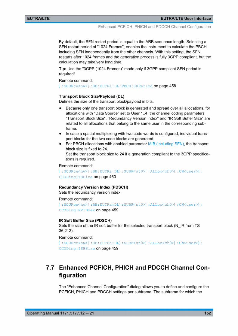
EUTRA/LTE User InterfaceEUTRA/LTE
152Operating Manual 1171.5177.12 ─ 21
By default, the SFN restart period is equal to the ARB sequence length. Selecting aSFN restart period of "1024 Frames", enables the instrument to calculate the PBCHincluding SFN independently from the other channels. With this setting, the SFNrestarts after 1024 frames and the generation process is fully 3GPP compliant, but thecalculation may take very long time.
Tip: Use the "3GPP (1024 Frames)" mode only if 3GPP compliant SFN period isrequired!
Remote command: [:SOURce<hw>]: BB: EUTRa:DL: PBCH:SRPeriod on page 458
Transport Block Size/Payload (DL)Defines the size of the transport block/payload in bits.
● Because only one transport block is generated and spread over all allocations, forallocations with "Data Source" set to User 1..4, the channel coding parameters"Transport Block Size", "Redundancy Version Index" and "IR Soft Buffer Size" arerelated to all allocations that belong to the same user in the corresponding sub-frame.
● In case a spatial multiplexing with two code words is configured, individual trans-port blocks for the two code blocks are generated.
● For PBCH allocations with enabled parameter MIB (including SFN), the transportblock size is fixed to 24.Set the transport block size to 24 if a generation compliant to the 3GPP specifica-tions is required.
Remote command: [:SOURce<hw>]: BB:EUTRa: DL[:SUBF<st0>]: ALLoc<ch0>[: CW<user>]: CCODing:TBSize on page 460
Redundancy Version Index (PDSCH)Sets the redundancy version index.
Remote command: [:SOURce<hw>]: BB:EUTRa: DL[:SUBF<st0>]: ALLoc<ch0>[: CW<user>]: CCODing: RVINdex on page 459
IR Soft Buffer Size (PDSCH)Sets the size of the IR soft buffer for the selected transport block (N_IR from TS36.212).
Remote command: [:SOURce<hw>]: BB:EUTRa: DL[:SUBF<st0>]: ALLoc<ch0>[: CW<user>]: CCODing: ISBSize on page 459
7.7 Enhanced PCFICH, PHICH and PDCCH Channel Con-figuration
The "Enhanced Channel Configuration" dialog allows you to define and configure thePCFICH, PHICH and PDCCH settings per subframe. The subframe for which the
Enhanced PCFICH, PHICH and PDCCH Channel Configuration
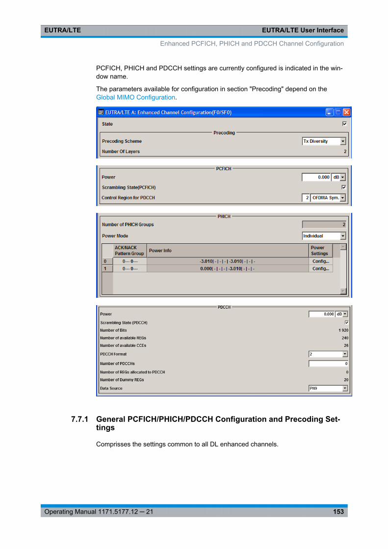
EUTRA/LTE User InterfaceEUTRA/LTE
153Operating Manual 1171.5177.12 ─ 21
PCFICH, PHICH and PDCCH settings are currently configured is indicated in the win-dow name.
The parameters available for configuration in section "Precoding" depend on theGlobal MIMO Configuration.
7.7.1 General PCFICH/PHICH/PDCCH Configuration and Precoding Set-tings
Comprisses the settings common to all DL enhanced channels.
Enhanced PCFICH, PHICH and PDCCH Channel Configuration
EUTRA/LTE User InterfaceEUTRA/LTE
154Operating Manual 1171.5177.12 ─ 21
StateEnables/disables the PDCCH, PCFICH and PHICH allocation.
Remote command: [:SOURce<hw>]: BB:EUTRa:DL[: SUBF<st0>]: ENCC:STATe on page 467
Precoding SchemeSelects the precoding scheme for PDCCH, PCFICH and PHICH.
"None" Disables precoding.
"Tx Diversity" Precoding for transmit diversity will be performed according to 3GPPTS 36.211 and the selected parameters.
Remote command: [:SOURce<hw>]: BB: EUTRa:DL[: SUBF<st0>]: ENCC:PRECoding: SCHeme on page 468
Number of Layers (Enhanced Channels)(Enabled for Precoding Scheme set to Tx Diversity)
Displays the number of layers for PDCCH, PCFICH and PHICH. This value is fixed to 1for PDCCH, PCFICH and PHICH.
Remote command: [:SOURce<hw>]: BB: EUTRa:DL[: SUBF<st0>]: ENCC:PRECoding: NOLayers? on page 468
Scrambling StateEnables/disables the scrambling of all DL enhanced channels.
Remote command: [:SOURce<hw>]: BB:EUTRa:DL[: SUBF<st0>]: ENCC:SCRambling: STATe on page 468
7.7.2 PCFICH Settings
Provided are the following settings:
PCFICH ConfigurationComprisses the PCFICH settings:
PCFICH Power ← PCFICH ConfigurationSets the power of the PCFICH (PPCFICH).
Remote command: [:SOURce<hw>]: BB: EUTRa:DL[: SUBF<st0>]: ENCC:PCFich: POWeron page 469
Control Region for PDCCH ← PCFICH ConfigurationSets the size of the control region, i.e. the number of OFDM Symbols that he regionspans.
Enhanced PCFICH, PHICH and PDCCH Channel Configuration
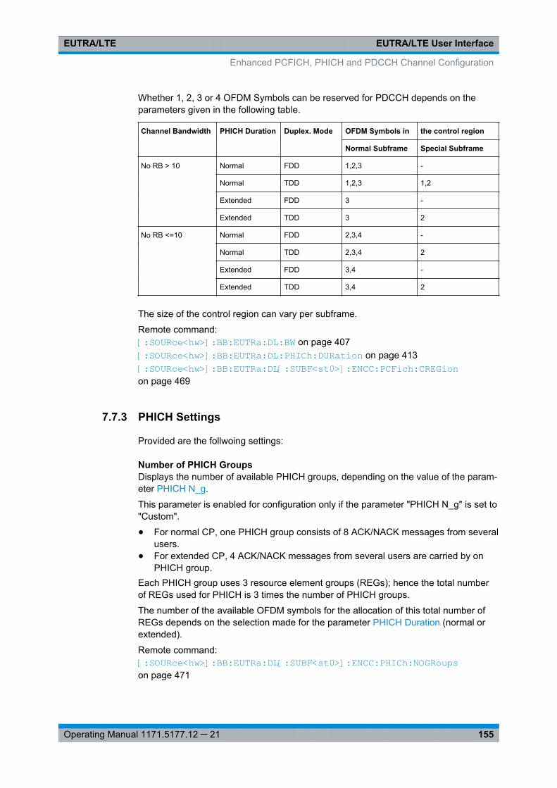
EUTRA/LTE User InterfaceEUTRA/LTE
155Operating Manual 1171.5177.12 ─ 21
Whether 1, 2, 3 or 4 OFDM Symbols can be reserved for PDCCH depends on theparameters given in the following table.
Channel Bandwidth PHICH Duration Duplex. Mode OFDM Symbols in the control region
Normal Subframe Special Subframe
No RB > 10 Normal FDD 1,2,3 -
Normal TDD 1,2,3 1,2
Extended FDD 3 -
Extended TDD 3 2
No RB <=10 Normal FDD 2,3,4 -
Normal TDD 2,3,4 2
Extended FDD 3,4 -
Extended TDD 3,4 2
The size of the control region can vary per subframe.
Remote command: [:SOURce<hw>]: BB: EUTRa:DL: BW on page 407[:SOURce<hw>]: BB: EUTRa:DL: PHICh:DURation on page 413[:SOURce<hw>]: BB: EUTRa:DL[: SUBF<st0>]: ENCC:PCFich: CREGion on page 469
7.7.3 PHICH Settings
Provided are the follwoing settings:
Number of PHICH GroupsDisplays the number of available PHICH groups, depending on the value of the param-eter PHICH N_g.
This parameter is enabled for configuration only if the parameter "PHICH N_g" is set to"Custom".
● For normal CP, one PHICH group consists of 8 ACK/NACK messages from severalusers.
● For extended CP, 4 ACK/NACK messages from several users are carried by onPHICH group.
Each PHICH group uses 3 resource element groups (REGs); hence the total numberof REGs used for PHICH is 3 times the number of PHICH groups.
The number of the available OFDM symbols for the allocation of this total number ofREGs depends on the selection made for the parameter PHICH Duration (normal orextended).
Remote command: [:SOURce<hw>]: BB:EUTRa: DL[:SUBF<st0>]: ENCC:PHICh: NOGRoupson page 471
Enhanced PCFICH, PHICH and PDCCH Channel Configuration
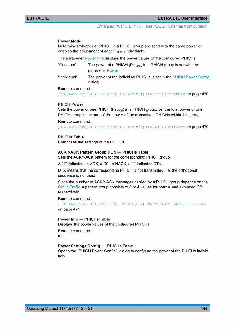
EUTRA/LTE User InterfaceEUTRA/LTE
156Operating Manual 1171.5177.12 ─ 21
Power ModeDetermines whether all PHICH in a PHICH group are send with the same power orenables the adjustment of each PPHICH individualy.
The parameter Power Info displays the power values of the configured PHICHs.
"Constant" The power of a PHICH (PPHICH) in a PHICH group is set with theparameter Power.
"Individual" The power of the individual PHICHs is set in the PHICH Power Configdialog.
Remote command: [:SOURce<hw>]: BB: EUTRa:DL[: SUBF<st0>]: ENCC:PHICh: PMODe on page 470
PHICH PowerSets the power of one PHICH (PPHICH) in a PHICH group, i.e. the total power of onePHICH group is the sum of the power of the transmitted PHICHs within this group.
Remote command: [:SOURce<hw>]: BB:EUTRa: DL[:SUBF<st0>]: ENCC:PHICh: POWer on page 470
PHICHs TableComprises the settings of the PHICHs.
ACK/NACK Pattern Group 0 .. 9 ← PHICHs TableSets the ACK/NACK pattern for the corresponding PHICH group.
A "1" indicates an ACK, a "0" - a NACK, a "-" indicates DTX.
DTX means that the corresponding PHICH is not transmitted, i.e. the orthogonalsequence is not used.
Since the number of ACK/NACK messages carried by a PHICH group depends on theCyclic Prefix, a pattern group consists of 8 or 4 values for normal and extended CPrespectively.
Remote command: [:SOURce<hw>]: BB:EUTRa: DL[:SUBF<st0>]: ENCC: PHICh: ANPattern<ch0> on page 471
Power Info ← PHICHs TableDisplays the power values of the configured PHICHs.
Remote command: n.a.
Power Settings Config. ← PHICHs TableOpens the "PHICH Power Config". dialog to configure the power of the PHICHs individ-ualy.
Enhanced PCFICH, PHICH and PDCCH Channel Configuration
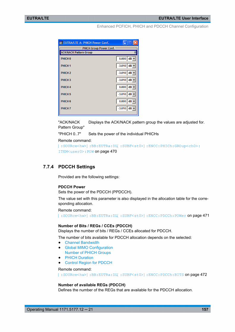
EUTRA/LTE User InterfaceEUTRA/LTE
157Operating Manual 1171.5177.12 ─ 21
"ACK/NACKPattern Group"
Displays the ACK/NACK pattern group the values are adjusted for.
"PHICH 0..7" Sets the power of the individual PHICHs
Remote command: [:SOURce<hw>]: BB: EUTRa:DL[: SUBF<st0>]: ENCC:PHICh: GROup<ch0>: ITEM<user0>: POW on page 470
7.7.4 PDCCH Settings
Provided are the following settings:
PDCCH PowerSets the power of the PDCCH (PPDCCH).
The value set with this parameter is also displayed in the allocation table for the corre-sponding allocation.
Remote command: [:SOURce<hw>]: BB:EUTRa:DL[: SUBF<st0>]: ENCC:PDCCh: POWer on page 471
Number of Bits / REGs / CCEs (PDCCH)Displays the number of bits / REGs / CCEs allocated for PDCCH.
The number of bits available for PDCCH allocation depends on the selected:● Channel Bandwidth● Global MIMO Configuration
Number of PHICH Groups● PHICH Duration● Control Region for PDCCH
Remote command: [:SOURce<hw>]: BB: EUTRa:DL[: SUBF<st0>]: ENCC:PDCCh: BITS on page 472
Number of available REGs (PDCCH)Defines the number of the REGs that are available for the PDCCH allocation.
Enhanced PCFICH, PHICH and PDCCH Channel Configuration
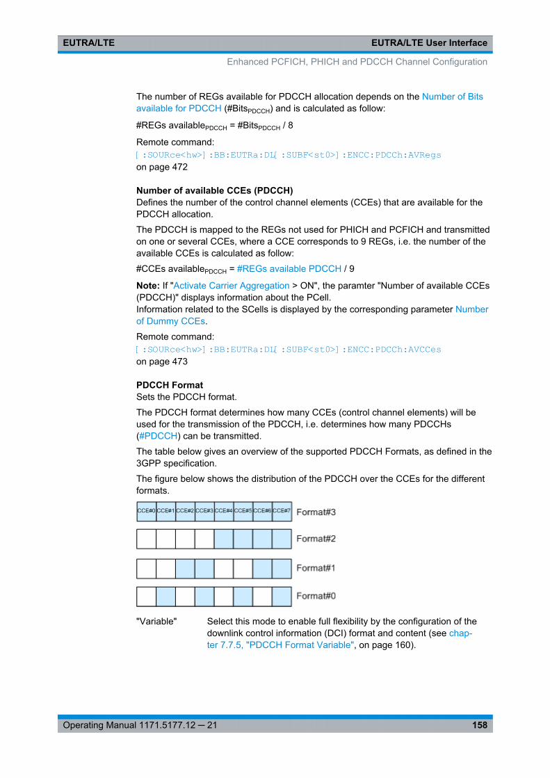
EUTRA/LTE User InterfaceEUTRA/LTE
158Operating Manual 1171.5177.12 ─ 21
The number of REGs available for PDCCH allocation depends on the Number of Bitsavailable for PDCCH (#BitsPDCCH) and is calculated as follow:
#REGs availablePDCCH = #BitsPDCCH / 8
Remote command: [:SOURce<hw>]: BB:EUTRa: DL[:SUBF<st0>]: ENCC: PDCCh: AVRegson page 472
Number of available CCEs (PDCCH)Defines the number of the control channel elements (CCEs) that are available for thePDCCH allocation.
The PDCCH is mapped to the REGs not used for PHICH and PCFICH and transmittedon one or several CCEs, where a CCE corresponds to 9 REGs, i.e. the number of theavailable CCEs is calculated as follow:
#CCEs availablePDCCH = #REGs available PDCCH / 9
Note: If "Activate Carrier Aggregation > ON", the paramter "Number of available CCEs(PDCCH)" displays information about the PCell.Information related to the SCells is displayed by the corresponding parameter Numberof Dummy CCEs.
Remote command: [:SOURce<hw>]: BB:EUTRa: DL[:SUBF<st0>]: ENCC:PDCCh: AVCCeson page 473
PDCCH FormatSets the PDCCH format.
The PDCCH format determines how many CCEs (control channel elements) will beused for the transmission of the PDCCH, i.e. determines how many PDCCHs(#PDCCH) can be transmitted.
The table below gives an overview of the supported PDCCH Formats, as defined in the3GPP specification.
The figure below shows the distribution of the PDCCH over the CCEs for the differentformats.
"Variable" Select this mode to enable full flexibility by the configuration of thedownlink control information (DCI) format and content (see chap-ter 7.7.5, "PDCCH Format Variable", on page 160).
Enhanced PCFICH, PHICH and PDCCH Channel Configuration
EUTRA/LTE User InterfaceEUTRA/LTE
159Operating Manual 1171.5177.12 ─ 21
"-1" Proprietary format for legacy support.
This format corresponds to the transmission of one PDCCH on allavailable REGs, i.e.● REGs available PDCCH = #REGs allocated PDCCH,● #PDCCH = 1,● #DummyREGs = 0.
"0" One PDCCH is transmitted on one CCE, i.e. #REG=1.
"1" One PDCCH is transmitted on two CCEs, i.e. #REG=18.
"2" One PDCCH is transmitted on four CCEs, i.e. #REG=36.
"3" One PDCCH is transmitted on eight CCEs, i.e. #REG=72.
Remote command: [:SOURce<hw>]: BB: EUTRa:DL[: SUBF<st0>]: ENCC:PDCCh: FORMaton page 473
Number of PDCCHs(for "PDCCH Format" different than "Variable")
Sets the number of PDCCHs to be transmitted.
The maximum number PDCCH that can be transmitted on the available REGs forPDCCH depends on the number of REGs (#REG) reserved for the transmission of onePDCCH, i.e. depends on the selected PDCCH Format and is calculated as follow:
#PDCCH = REGs available PDCCH / #REG.
Remote command: [: SOURce<hw>]: BB:EUTRa: DL[:SUBF<st0>]: ENCC: PDCCh:NOPDcchs on page 474
Number of REGs allocated to PDCCH(for "PDCCH Format" different than "Variable")
Defines the number of REGs that are actually allocated for PDCCH transmission(#REGs allocatedPDCCH) and is calculated as follow:
#REGs allocatedPDCCH = #PDCCH * #REG
Remote command: [:SOURce<hw>]: BB: EUTRa:DL[: SUBF<st0>]: ENCC:PDCCh: ALRegson page 475
Number of Dummy REGs(for "PDCCH Format" different than "Variable")
Displays the number of REGs that are available for the PDCCH allocation but are notallocated and is calculated as follow:
#DummyREGs = REGs available PDCCH - #REGs allocated PDCCH.
Remote command: [:SOURce<hw>]: BB:EUTRa: DL[:SUBF<st0>]: ENCC: PDCCh: DREGs on page 475
Enhanced PCFICH, PHICH and PDCCH Channel Configuration
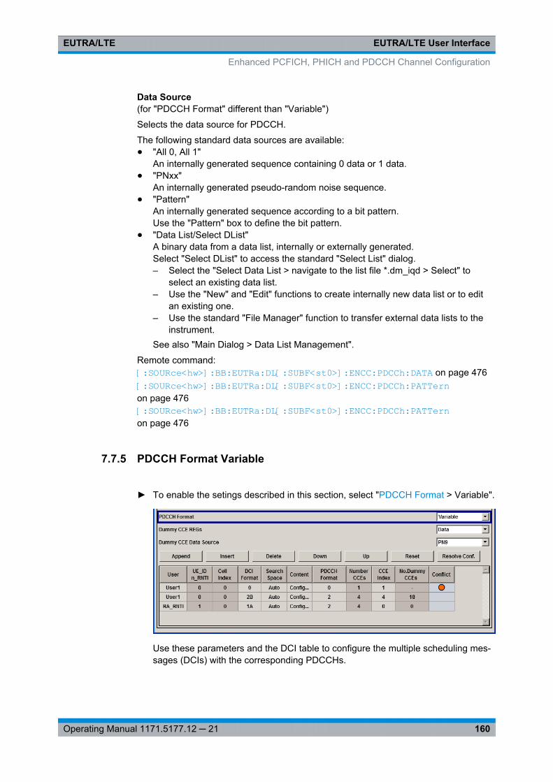
EUTRA/LTE User InterfaceEUTRA/LTE
160Operating Manual 1171.5177.12 ─ 21
Data Source(for "PDCCH Format" different than "Variable")
Selects the data source for PDCCH.
The following standard data sources are available:● "All 0, All 1"
An internally generated sequence containing 0 data or 1 data.● "PNxx"
An internally generated pseudo-random noise sequence.● "Pattern"
An internally generated sequence according to a bit pattern.Use the "Pattern" box to define the bit pattern.
● "Data List/Select DList"A binary data from a data list, internally or externally generated.Select "Select DList" to access the standard "Select List" dialog.– Select the "Select Data List > navigate to the list file *.dm_iqd > Select" to
select an existing data list.– Use the "New" and "Edit" functions to create internally new data list or to edit
an existing one.– Use the standard "File Manager" function to transfer external data lists to the
instrument.See also "Main Dialog > Data List Management".
Remote command: [:SOURce<hw>]: BB: EUTRa:DL[: SUBF<st0>]: ENCC:PDCCh: DATA on page 476[:SOURce<hw>]: BB: EUTRa:DL[: SUBF<st0>]: ENCC:PDCCh: PATTern on page 476[:SOURce<hw>]: BB: EUTRa:DL[: SUBF<st0>]: ENCC:PDCCh: PATTern on page 476
7.7.5 PDCCH Format Variable
► To enable the setings described in this section, select "PDCCH Format > Variable".
Use these parameters and the DCI table to configure the multiple scheduling mes-sages (DCIs) with the corresponding PDCCHs.
Enhanced PCFICH, PHICH and PDCCH Channel Configuration
EUTRA/LTE User InterfaceEUTRA/LTE
161Operating Manual 1171.5177.12 ─ 21
Dummy CCE REGsSets the behavior of the dummy REGs, i.e. determines whether dummy data or DTX istransmitted.
Remote command: [:SOURce<hw>]: BB: EUTRa:DL[: SUBF<st0>]: ENCC:PDCCh: DCRegs:TRSource on page 477
Dummy CCE Data SourceSelects the data source for the dummy CCE.
The following standard data sources are available:● "All 0, All 1"
An internally generated sequence containing 0 data or 1 data.● "PNxx"
An internally generated pseudo-random noise sequence.● "Pattern"
An internally generated sequence according to a bit pattern.Use the "Pattern" box to define the bit pattern.
● "Data List/Select DList"A binary data from a data list, internally or externally generated.Select "Select DList" to access the standard "Select List" dialog.– Select the "Select Data List > navigate to the list file *.dm_iqd > Select" to
select an existing data list.– Use the "New" and "Edit" functions to create internally new data list or to edit
an existing one.– Use the standard "File Manager" function to transfer external data lists to the
instrument.See also "Main Dialog > Data List Management".
Remote command: [:SOURce<hw>]: BB: EUTRa:DL[: SUBF<st0>]: ENCC:PDCCh: DCRegs:DATA on page 477[:SOURce<hw>]: BB: EUTRa:DL[: SUBF<st0>]: ENCC:PDCCh: DCRegs:PATTern on page 478[:SOURce<hw>]: BB: EUTRa:DL[: SUBF<st0>]: ENCC:PDCCh: DCRegs:DSELect on page 477
Standard configuration functionsStandard configuration functions:
"Append" Adds a new row at the end of the table.
Remote command: [:SOURce<hw>]: BB: EUTRa:DL[: SUBF<st0>]: ENCC:PDCCh: EXTC:APPend on page 479
"Insert" Insert a new row before the current one.
Remote command: [:SOURce<hw>]: BB: EUTRa:DL[: SUBF<st0>]: ENCC:PDCCh: EXTC:SITem on page 478[:SOURce<hw>]: BB: EUTRa:DL[: SUBF<st0>]: ENCC:PDCCh: EXTC:INSert on page 479
Enhanced PCFICH, PHICH and PDCCH Channel Configuration
EUTRA/LTE User InterfaceEUTRA/LTE
162Operating Manual 1171.5177.12 ─ 21
"Delete" Deletes the selected row.
Remote command: [:SOURce<hw>]: BB: EUTRa:DL[: SUBF<st0>]: ENCC:PDCCh: EXTC:DELete on page 479
"Down/Up" Moves the selected row down or up.
Remote command: [:SOURce<hw>]: BB: EUTRa:DL[: SUBF<st0>]: ENCC:PDCCh: EXTC:DOWN on page 479[:SOURce<hw>]: BB: EUTRa:DL[: SUBF<st0>]: ENCC:PDCCh: EXTC:UPon page 479
ResetResets the table.
Remote command: [: SOURce<hw>]: BB:EUTRa: DL[:SUBF<st0>]: ENCC: PDCCh:EXTC: RESeton page 481
Resolve ConflictsThe "Resolve Conf." is a built-in algorithm that re-assigns automatically the CCE val-ues depending on the configured "Search Space"; previously configured CCE valueswill not be maintained. If the conflict can not be resolved automatically, the values areleft unchanged.
For more information on how to solve DCI conflicts, see chapter 5.1.3, "DCI ConflictHandling", on page 51.
Remote command: [:SOURce<hw>]: BB:EUTRa: DL[:SUBF<st0>]: ENCC:PDCCh: EXTC: SOLVe?on page 480to query the number of current conflicts:[:SOURce<hw>]: BB:EUTRa: DL[:SUBF<st0>]: ENCC:PDCCh: EXTC: CONFlicts? on page 480
DCI TableComprises the settings concerning the PDCCH content.
Number of Used PDCCH Items ← DCI TableDisplays the number of the PDCCH items, i.e. the number of rows in the DCI table.
Remote command: [:SOURce<hw>]: BB: EUTRa: DL[: SUBF<st0>]: ENCC:PDCCh: EXTC:UITems? on page 481
User ← DCI TableSelects the User the DCI is dedicated to. The available DCI Format depend on thevalue of this parameter.
Note: If "Activate Carrier Aggregation > ON", the Cell Index determines the componentcarrier the corresponding User is mapped to. To enable one particular User in morethan one component carrier, append several table rows and enable the same User inthe different component carriers.
Enhanced PCFICH, PHICH and PDCCH Channel Configuration
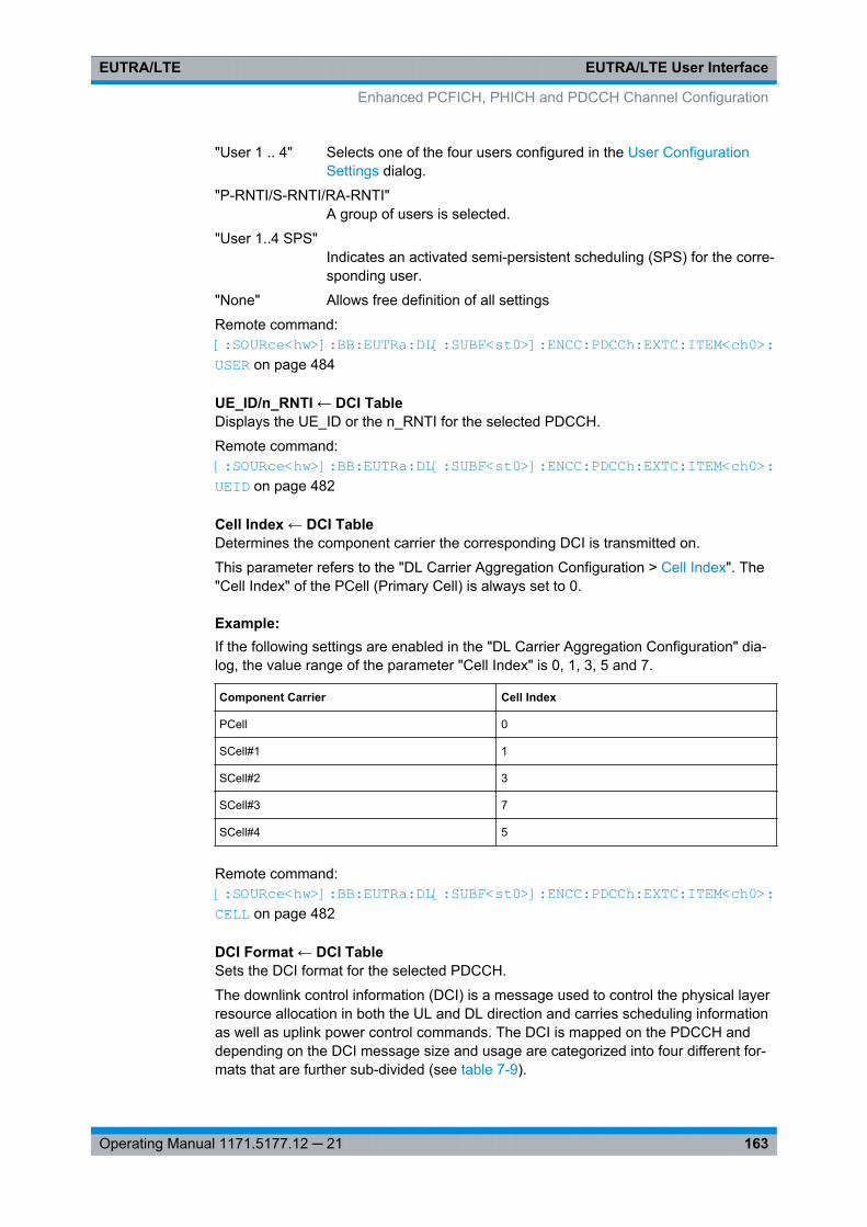
EUTRA/LTE User InterfaceEUTRA/LTE
163Operating Manual 1171.5177.12 ─ 21
"User 1 .. 4" Selects one of the four users configured in the User ConfigurationSettings dialog.
"P-RNTI/S-RNTI/RA-RNTI"A group of users is selected.
"User 1..4 SPS"Indicates an activated semi-persistent scheduling (SPS) for the corre-sponding user.
"None" Allows free definition of all settings
Remote command: [:SOURce<hw>]: BB: EUTRa:DL[: SUBF<st0>]: ENCC:PDCCh: EXTC:ITEM<ch0>: USER on page 484
UE_ID/n_RNTI ← DCI TableDisplays the UE_ID or the n_RNTI for the selected PDCCH.
Remote command: [:SOURce<hw>]: BB:EUTRa:DL[: SUBF<st0>]: ENCC:PDCCh: EXTC:ITEM<ch0>: UEID on page 482
Cell Index ← DCI TableDetermines the component carrier the corresponding DCI is transmitted on.
This parameter refers to the "DL Carrier Aggregation Configuration > Cell Index". The"Cell Index" of the PCell (Primary Cell) is always set to 0.
Example: If the following settings are enabled in the "DL Carrier Aggregation Configuration" dia-log, the value range of the parameter "Cell Index" is 0, 1, 3, 5 and 7.
Component Carrier Cell Index
PCell 0
SCell#1 1
SCell#2 3
SCell#3 7
SCell#4 5
Remote command: [:SOURce<hw>]: BB: EUTRa:DL[: SUBF<st0>]: ENCC:PDCCh: EXTC:ITEM<ch0>: CELL on page 482
DCI Format ← DCI TableSets the DCI format for the selected PDCCH.
The downlink control information (DCI) is a message used to control the physical layerresource allocation in both the UL and DL direction and carries scheduling informationas well as uplink power control commands. The DCI is mapped on the PDCCH anddepending on the DCI message size and usage are categorized into four different for-mats that are further sub-divided (see table 7-9).
Enhanced PCFICH, PHICH and PDCCH Channel Configuration
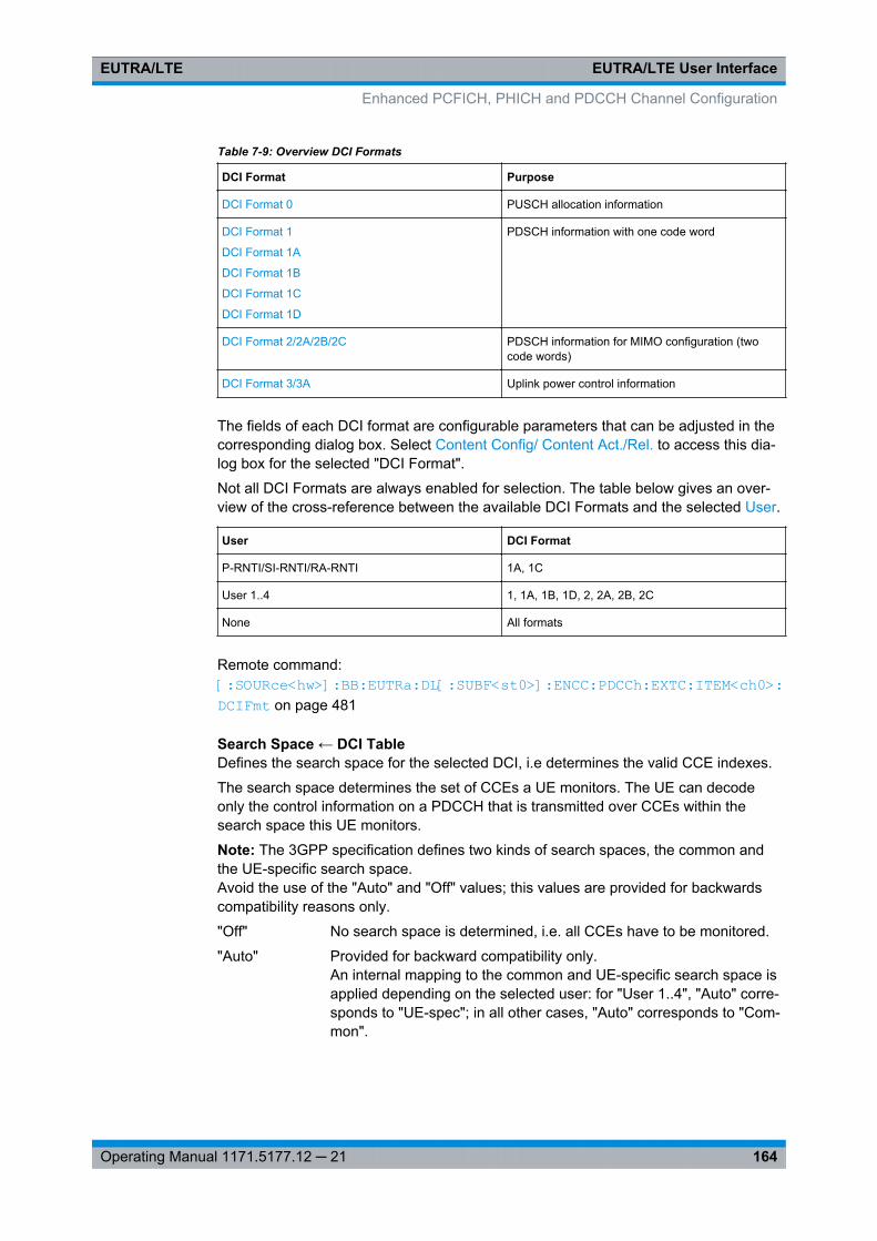
EUTRA/LTE User InterfaceEUTRA/LTE
164Operating Manual 1171.5177.12 ─ 21
Table 7-9: Overview DCI Formats
DCI Format Purpose
DCI Format 0 PUSCH allocation information
DCI Format 1
DCI Format 1A
DCI Format 1B
DCI Format 1C
DCI Format 1D
PDSCH information with one code word
DCI Format 2/2A/2B/2C PDSCH information for MIMO configuration (twocode words)
DCI Format 3/3A Uplink power control information
The fields of each DCI format are configurable parameters that can be adjusted in thecorresponding dialog box. Select Content Config/ Content Act./Rel. to access this dia-log box for the selected "DCI Format".
Not all DCI Formats are always enabled for selection. The table below gives an over-view of the cross-reference between the available DCI Formats and the selected User.
User DCI Format
P-RNTI/SI-RNTI/RA-RNTI 1A, 1C
User 1..4 1, 1A, 1B, 1D, 2, 2A, 2B, 2C
None All formats
Remote command: [:SOURce<hw>]: BB: EUTRa:DL[: SUBF<st0>]: ENCC:PDCCh: EXTC:ITEM<ch0>: DCIFmt on page 481
Search Space ← DCI TableDefines the search space for the selected DCI, i.e determines the valid CCE indexes.
The search space determines the set of CCEs a UE monitors. The UE can decodeonly the control information on a PDCCH that is transmitted over CCEs within thesearch space this UE monitors.
Note: The 3GPP specification defines two kinds of search spaces, the common andthe UE-specific search space.Avoid the use of the "Auto" and "Off" values; this values are provided for backwardscompatibility reasons only.
"Off" No search space is determined, i.e. all CCEs have to be monitored.
"Auto" Provided for backward compatibility only.An internal mapping to the common and UE-specific search space isapplied depending on the selected user: for "User 1..4", "Auto" corre-sponds to "UE-spec"; in all other cases, "Auto" corresponds to "Com-mon".
Enhanced PCFICH, PHICH and PDCCH Channel Configuration
EUTRA/LTE User InterfaceEUTRA/LTE
165Operating Manual 1171.5177.12 ─ 21
"Common" The DCI is mapped to the common search space.A common search space is used when all or a group of UEs areaddressed. The combination User 1 and common search space isenabled in PCell only.
"UE-spec" Non-common DCIs are mapped to the UE-specific search space.Each UE has multiple UE-specific search space, determined as afunction of the UE_ID and the subframe. A UE-specific search spaceapplies for the User set to "User 1..4".
Remote command: [:SOURce<hw>]: BB: EUTRa:DL[: SUBF<st0>]: ENCC:PDCCh: EXTC:ITEM<ch0>: SESPace on page 485
Content Config/ Content Act./Rel. ← DCI TableOpens the 166 dialog to configure the DCI fields of the selected DCI Format.
In the activation and release subframes of users that are semi-persistent scheduled(User > User x SPS), the function "Act./Rel." accesses the 166 dialog to configure thespecial fields for the SPS validation.
Remote command: n.a.
PDCCH Format (Variable) ← DCI TableSets the PDCCH format.
The PDCCH format determines how many CCEs (control channel elements) will beused for the transmission of the PDCCH.
The table below gives an overview of the supported PDCCH Formats, as defined in the3GPP specification.
PDCCH format Number of CCEs Number of REGs Number of PDCCH bits
0 1 9 72
1 2 18 144
2 4 36 288
3 8 72 576
"0" One PDCCH is transmitted on one CCE, i.e. #REG=1.
"1" One PDCCH is transmitted on two CCEs, i.e. #REG=18.
"2" One PDCCH is transmitted on four CCEs, i.e. #REG=36.
"3" One PDCCH is transmitted on eight CCEs, i.e. #REG=72.
Remote command: [:SOURce<hw>]: BB: EUTRa:DL[: SUBF<st0>]: ENCC:PDCCh: EXTC:ITEM<ch0>: PFMT on page 482
Number CCEs ← DCI TableDefines the number of control channel elements used for the transmission of thePDCCH.
Enhanced PCFICH, PHICH and PDCCH Channel Configuration
EUTRA/LTE User InterfaceEUTRA/LTE
166Operating Manual 1171.5177.12 ─ 21
The value is determined by the selected PDCCH Format (Variable).
Remote command: [:SOURce<hw>]: BB: EUTRa:DL[: SUBF<st0>]: ENCC:PDCCh: EXTC:ITEM<ch0>: NCCes on page 483
CCE Index ← DCI TableSets the CCE start index.
Remote command: [: SOURce<hw>]: BB:EUTRa: DL[:SUBF<st0>]: ENCC: PDCCh:EXTC: ITEM<ch0>: CINDex on page 483
Number of Dummy CCEs ← DCI TableDefines the number of dummy CCEs that are appended to the corresponding PDCCH.
Note: If "Activate Carrier Aggregation > ON", the "Number of Dummy CCEs" is calcula-ted per component carrier and depends on the selected Bandwidth.
Remote command: [:SOURce<hw>]: BB: EUTRa:DL[: SUBF<st0>]: ENCC:PDCCh: EXTC:ITEM<ch0>: NDCCes on page 483
Conflict (DCI) ← DCI TableIndicates a conflict between two DCI formats.
For more information on how to solve DCI conflicts, see chapter 5.1.3, "DCI ConflictHandling", on page 51.
Remote command: [:SOURce<hw>]: BB:EUTRa: DL[:SUBF<st0>]: ENCC: PDCCh: EXTC:ITEM<ch0>: CONFlict? on page 484[:SOURce<hw>]: BB:EUTRa: DL[:SUBF<st0>]: ENCC: PDCCh: EXTC:CONFlicts? on page 480
7.7.6 DCI Format Configuration
Carrier Indicator Field (CIF)(Requires option R&S SMx/AMU-K85 LTE-A Rel. 10)
This field is enabled if the "Activate Carrier Aggregation > ON" and for User withenabled "Configure User > Activate CA".
The CIF is present in each DCI Format and indentifies the component carrier that car-ries the PDSCH or PUSCH for the particuliar PDCCH in the cross-carrier approach(see figure 3-26).
According to the LTE specification, cross-carrier scheduling is enabled by higher-levelsignaling. To enable cross-carrier scheduling in this implementation, enable the "DLCarrier Aggregation Configuration>CIF Present" for component carrier/cell.
Remote command: [:SOURce<hw>]: BB:EUTRa: DL[:SUBF<st0>]: ENCC: PDCCh: EXTC:ITEM<ch0>: DCIConf: CIField on page 486
Enhanced PCFICH, PHICH and PDCCH Channel Configuration
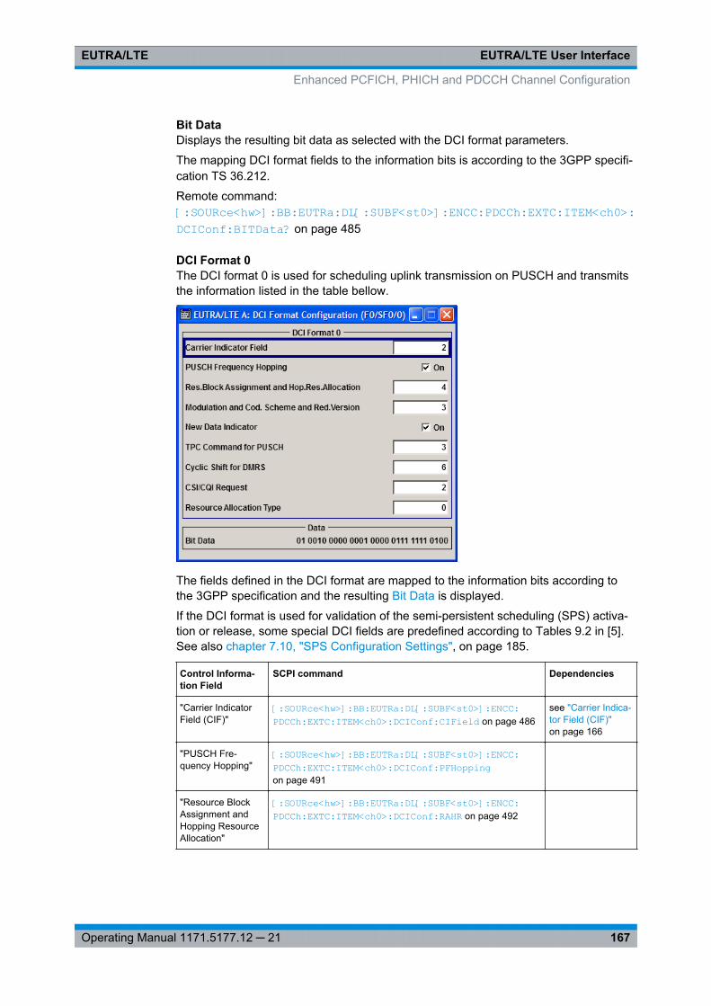
EUTRA/LTE User InterfaceEUTRA/LTE
167Operating Manual 1171.5177.12 ─ 21
Bit DataDisplays the resulting bit data as selected with the DCI format parameters.
The mapping DCI format fields to the information bits is according to the 3GPP specifi-cation TS 36.212.
Remote command: [:SOURce<hw>]: BB:EUTRa:DL[: SUBF<st0>]: ENCC:PDCCh: EXTC:ITEM<ch0>: DCIConf: BITData? on page 485
DCI Format 0The DCI format 0 is used for scheduling uplink transmission on PUSCH and transmitsthe information listed in the table bellow.
The fields defined in the DCI format are mapped to the information bits according tothe 3GPP specification and the resulting Bit Data is displayed.
If the DCI format is used for validation of the semi-persistent scheduling (SPS) activa-tion or release, some special DCI fields are predefined according to Tables 9.2 in [5].See also chapter 7.10, "SPS Configuration Settings", on page 185.
Control Informa-tion Field
SCPI command Dependencies
"Carrier IndicatorField (CIF)"
[:SOURce<hw>]: BB: EUTRa:DL[: SUBF<st0>]: ENCC:PDCCh: EXTC:ITEM<ch0>: DCIConf: CIField on page 486
see "Carrier Indica-tor Field (CIF)"on page 166
"PUSCH Fre-quency Hopping"
[:SOURce<hw>]: BB: EUTRa:DL[: SUBF<st0>]: ENCC:PDCCh: EXTC:ITEM<ch0>: DCIConf: PFHopping on page 491
"Resource BlockAssignment andHopping ResourceAllocation"
[:SOURce<hw>]: BB: EUTRa:DL[: SUBF<st0>]: ENCC:PDCCh: EXTC:ITEM<ch0>: DCIConf: RAHR on page 492
Enhanced PCFICH, PHICH and PDCCH Channel Configuration
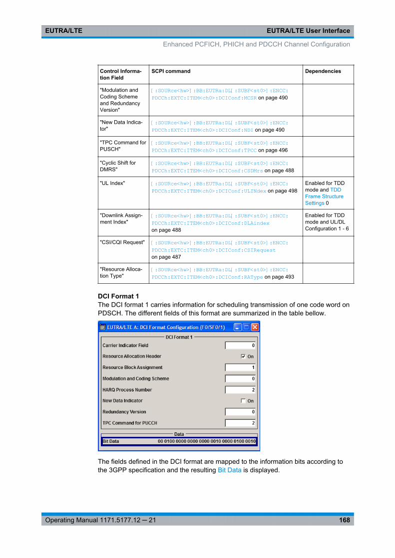
EUTRA/LTE User InterfaceEUTRA/LTE
168Operating Manual 1171.5177.12 ─ 21
Control Informa-tion Field
SCPI command Dependencies
"Modulation andCoding Schemeand RedundancyVersion"
[:SOURce<hw>]: BB: EUTRa:DL[: SUBF<st0>]: ENCC:PDCCh: EXTC:ITEM<ch0>: DCIConf: MCSR on page 490
"New Data Indica-tor"
[:SOURce<hw>]: BB: EUTRa:DL[: SUBF<st0>]: ENCC:PDCCh: EXTC:ITEM<ch0>: DCIConf: NDI on page 490
"TPC Command forPUSCH"
[:SOURce<hw>]: BB: EUTRa:DL[: SUBF<st0>]: ENCC:PDCCh: EXTC:ITEM<ch0>: DCIConf: TPCC on page 496
"Cyclic Shift forDMRS"
[:SOURce<hw>]: BB: EUTRa:DL[: SUBF<st0>]: ENCC:PDCCh: EXTC:ITEM<ch0>: DCIConf: CSDMrs on page 488
"UL Index" [:SOURce<hw>]: BB: EUTRa:DL[: SUBF<st0>]: ENCC:PDCCh: EXTC:ITEM<ch0>: DCIConf: ULINdex on page 498
Enabled for TDDmode and TDDFrame StructureSettings 0
"Downlink Assign-ment Index"
[:SOURce<hw>]: BB: EUTRa:DL[: SUBF<st0>]: ENCC:PDCCh: EXTC:ITEM<ch0>: DCIConf: DLAindex on page 488
Enabled for TDDmode and UL/DLConfiguration 1 - 6
"CSI/CQI Request" [:SOURce<hw>]: BB: EUTRa:DL[: SUBF<st0>]: ENCC:PDCCh: EXTC:ITEM<ch0>: DCIConf: CSIRequest on page 487
"Resource Alloca-tion Type"
[:SOURce<hw>]: BB: EUTRa:DL[: SUBF<st0>]: ENCC:PDCCh: EXTC:ITEM<ch0>: DCIConf: RAType on page 493
DCI Format 1The DCI format 1 carries information for scheduling transmission of one code word onPDSCH. The different fields of this format are summarized in the table bellow.
The fields defined in the DCI format are mapped to the information bits according tothe 3GPP specification and the resulting Bit Data is displayed.
Enhanced PCFICH, PHICH and PDCCH Channel Configuration
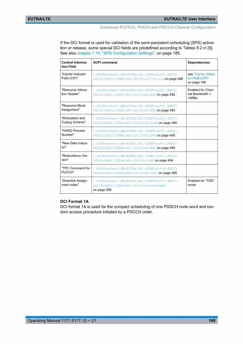
EUTRA/LTE User InterfaceEUTRA/LTE
169Operating Manual 1171.5177.12 ─ 21
If the DCI format is used for validation of the semi-persistent scheduling (SPS) activa-tion or release, some special DCI fields are predefined according to Tables 9.2 in [5].See also chapter 7.10, "SPS Configuration Settings", on page 185.
Control Informa-tion Field
SCPI command Dependencies
"Carrier IndicatorField (CIF)"
[:SOURce<hw>]: BB: EUTRa:DL[: SUBF<st0>]: ENCC:PDCCh: EXTC:ITEM<ch0>: DCIConf: CIField on page 486
see "Carrier Indica-tor Field (CIF)"on page 166
"Resource Alloca-tion Header"
[:SOURce<hw>]: BB: EUTRa:DL[: SUBF<st0>]: ENCC:PDCCh: EXTC:ITEM<ch0>: DCIConf: RAH on page 492
Enabled for Chan-nel Bandwidth >10RBs
"Resource BlockAssignment"
[:SOURce<hw>]: BB: EUTRa:DL[: SUBF<st0>]: ENCC:PDCCh: EXTC:ITEM<ch0>: DCIConf: RBA on page 493
"Modulation andCoding Scheme"
[:SOURce<hw>]: BB: EUTRa:DL[: SUBF<st0>]: ENCC:PDCCh: EXTC:ITEM<ch0>: DCIConf: MCSR on page 490
"HARQ ProcessNumber"
[:SOURce<hw>]: BB: EUTRa:DL[: SUBF<st0>]: ENCC:PDCCh: EXTC:ITEM<ch0>: DCIConf: HPN on page 490
"New Data Indica-tor"
[:SOURce<hw>]: BB: EUTRa:DL[: SUBF<st0>]: ENCC:PDCCh: EXTC:ITEM<ch0>: DCIConf: NDI on page 490
"Redundancy Ver-sion"
[:SOURce<hw>]: BB: EUTRa:DL[: SUBF<st0>]: ENCC:PDCCh: EXTC:ITEM<ch0>: DCIConf: RV on page 494
"TPC Command forPUCCH"
[:SOURce<hw>]: BB: EUTRa:DL[: SUBF<st0>]: ENCC:PDCCh: EXTC:ITEM<ch0>: DCIConf: TPCC on page 496
"Downlink Assign-ment Index"
[:SOURce<hw>]: BB: EUTRa:DL[: SUBF<st0>]: ENCC:PDCCh: EXTC:ITEM<ch0>: DCIConf: DLAindex on page 488
Enabled for "TDD"mode
DCI Format 1ADCI format 1A is used for the compact scheduling of one PDSCH code word and ran-dom access procedure initiated by a PDCCH order.
Enhanced PCFICH, PHICH and PDCCH Channel Configuration
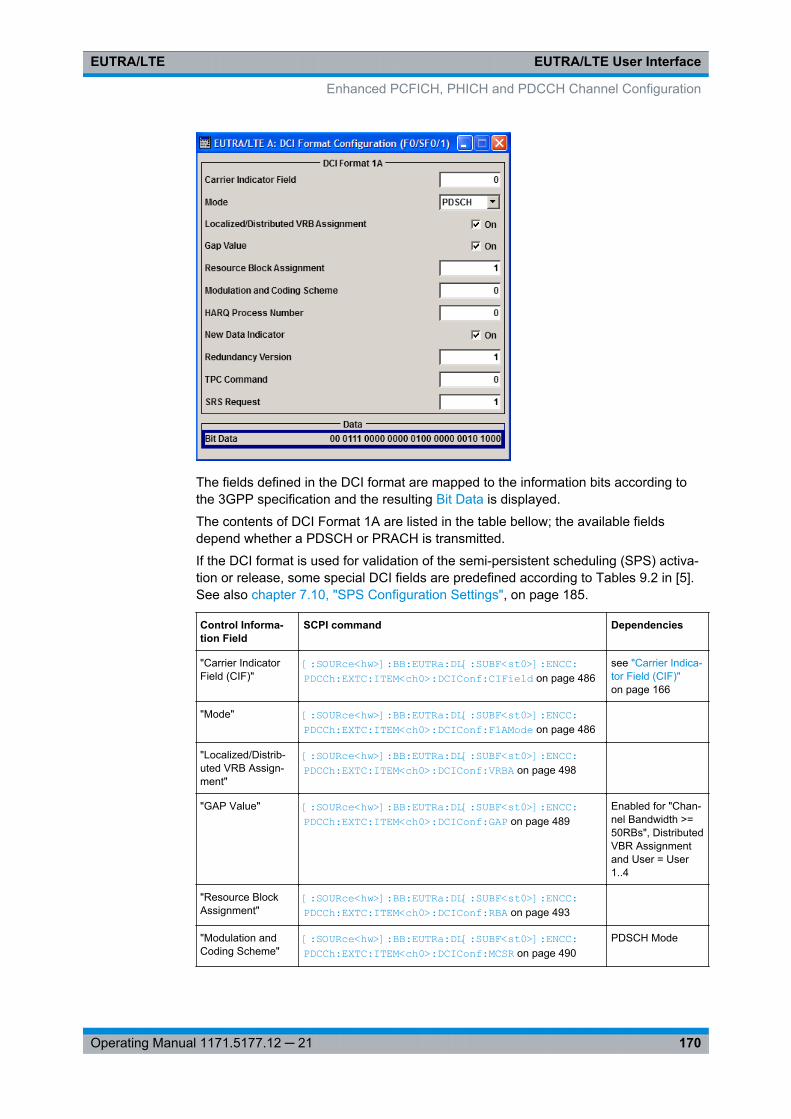
EUTRA/LTE User InterfaceEUTRA/LTE
170Operating Manual 1171.5177.12 ─ 21
The fields defined in the DCI format are mapped to the information bits according tothe 3GPP specification and the resulting Bit Data is displayed.
The contents of DCI Format 1A are listed in the table bellow; the available fieldsdepend whether a PDSCH or PRACH is transmitted.
If the DCI format is used for validation of the semi-persistent scheduling (SPS) activa-tion or release, some special DCI fields are predefined according to Tables 9.2 in [5].See also chapter 7.10, "SPS Configuration Settings", on page 185.
Control Informa-tion Field
SCPI command Dependencies
"Carrier IndicatorField (CIF)"
[:SOURce<hw>]: BB: EUTRa:DL[: SUBF<st0>]: ENCC:PDCCh: EXTC:ITEM<ch0>: DCIConf: CIField on page 486
see "Carrier Indica-tor Field (CIF)"on page 166
"Mode" [:SOURce<hw>]: BB: EUTRa:DL[: SUBF<st0>]: ENCC:PDCCh: EXTC:ITEM<ch0>: DCIConf: F1AMode on page 486
"Localized/Distrib-uted VRB Assign-ment"
[:SOURce<hw>]: BB: EUTRa:DL[: SUBF<st0>]: ENCC:PDCCh: EXTC:ITEM<ch0>: DCIConf: VRBA on page 498
"GAP Value" [:SOURce<hw>]: BB: EUTRa:DL[: SUBF<st0>]: ENCC:PDCCh: EXTC:ITEM<ch0>: DCIConf: GAP on page 489
Enabled for "Chan-nel Bandwidth >=50RBs", DistributedVBR Assignmentand User = User1..4
"Resource BlockAssignment"
[:SOURce<hw>]: BB: EUTRa:DL[: SUBF<st0>]: ENCC:PDCCh: EXTC:ITEM<ch0>: DCIConf: RBA on page 493
"Modulation andCoding Scheme"
[:SOURce<hw>]: BB: EUTRa:DL[: SUBF<st0>]: ENCC:PDCCh: EXTC:ITEM<ch0>: DCIConf: MCSR on page 490
PDSCH Mode
Enhanced PCFICH, PHICH and PDCCH Channel Configuration
EUTRA/LTE User InterfaceEUTRA/LTE
171Operating Manual 1171.5177.12 ─ 21
Control Informa-tion Field
SCPI command Dependencies
"HARQ ProcessNumber"
[:SOURce<hw>]: BB: EUTRa:DL[: SUBF<st0>]: ENCC:PDCCh: EXTC:ITEM<ch0>: DCIConf: HPN on page 490
PDSCH Mode
"New Data Indica-tor"
[:SOURce<hw>]: BB: EUTRa:DL[: SUBF<st0>]: ENCC:PDCCh: EXTC:ITEM<ch0>: DCIConf: NDI on page 490
PDSCH Mode
"Redundancy Ver-sion"
[:SOURce<hw>]: BB: EUTRa:DL[: SUBF<st0>]: ENCC:PDCCh: EXTC:ITEM<ch0>: DCIConf: RV on page 494
PDSCH Mode
"TPC Command forPUCCH"
[:SOURce<hw>]: BB: EUTRa:DL[: SUBF<st0>]: ENCC:PDCCh: EXTC:ITEM<ch0>: DCIConf: TPCC on page 496
PDSCH Mode
"Downlink Assign-ment Index"
[:SOURce<hw>]: BB: EUTRa:DL[: SUBF<st0>]: ENCC:PDCCh: EXTC:ITEM<ch0>: DCIConf: DLAindex on page 488
PDSCH ModeEnabled for "TDD"mode
"SRS Request" [:SOURce<hw>]: BB: EUTRa:DL[: SUBF<st0>]: ENCC:PDCCh: EXTC:ITEM<ch0>: DCIConf: SRSRequest on page 494
Enabled for "UserConfiguration >User 1..4 > Apperi-odic SRS > On"
"Preamble Index" [:SOURce<hw>]: BB: EUTRa:DL[: SUBF<st0>]: ENCC:PDCCh: EXTC:ITEM<ch0>: DCIConf: PRACh:PRINdex on page 486
PRACH Mode
"PRACH MaskIndex"
[:SOURce<hw>]: BB: EUTRa:DL[: SUBF<st0>]: ENCC:PDCCh: EXTC:ITEM<ch0>: DCIConf: PRACh:MINDex on page 487
PRACH Mode
DCI Format 1BDCI format 1B is used for the compact scheduling of one PDSCH code word with pre-coding information, i.e. when MIMO operation is involved.
The precoding information consists of 2 or 4 bits for 2 and 4 antennas respectively.
Enhanced PCFICH, PHICH and PDCCH Channel Configuration
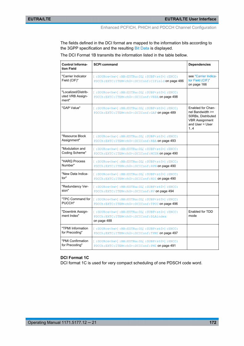
EUTRA/LTE User InterfaceEUTRA/LTE
172Operating Manual 1171.5177.12 ─ 21
The fields defined in the DCI format are mapped to the information bits according tothe 3GPP specification and the resulting Bit Data is displayed.
The DCI Format 1B transmits the information listed in the table bellow.
Control Informa-tion Field
SCPI command Dependencies
"Carrier IndicatorField (CIF)"
[:SOURce<hw>]: BB: EUTRa:DL[: SUBF<st0>]: ENCC:PDCCh: EXTC:ITEM<ch0>: DCIConf: CIField on page 486
see "Carrier Indica-tor Field (CIF)"on page 166
"Localized/Distrib-uted VRB Assign-ment"
[:SOURce<hw>]: BB: EUTRa:DL[: SUBF<st0>]: ENCC:PDCCh: EXTC:ITEM<ch0>: DCIConf: VRBA on page 498
"GAP Value" [:SOURce<hw>]: BB: EUTRa:DL[: SUBF<st0>]: ENCC:PDCCh: EXTC:ITEM<ch0>: DCIConf: GAP on page 489
Enabled for Chan-nel Bandwidth >=50RBs, DistributedVBR Assignmentand User = User1..4
"Resource BlockAssignment"
[:SOURce<hw>]: BB: EUTRa:DL[: SUBF<st0>]: ENCC:PDCCh: EXTC:ITEM<ch0>: DCIConf: RBA on page 493
"Modulation andCoding Scheme"
[:SOURce<hw>]: BB: EUTRa:DL[: SUBF<st0>]: ENCC:PDCCh: EXTC:ITEM<ch0>: DCIConf: MCSR on page 490
"HARQ ProcessNumber"
[:SOURce<hw>]: BB: EUTRa:DL[: SUBF<st0>]: ENCC:PDCCh: EXTC:ITEM<ch0>: DCIConf: HPN on page 490
"New Data Indica-tor"
[:SOURce<hw>]: BB: EUTRa:DL[: SUBF<st0>]: ENCC:PDCCh: EXTC:ITEM<ch0>: DCIConf: NDI on page 490
"Redundancy Ver-sion"
[:SOURce<hw>]: BB: EUTRa:DL[: SUBF<st0>]: ENCC:PDCCh: EXTC:ITEM<ch0>: DCIConf: RV on page 494
"TPC Command forPUCCH"
[:SOURce<hw>]: BB: EUTRa:DL[: SUBF<st0>]: ENCC:PDCCh: EXTC:ITEM<ch0>: DCIConf: TPCC on page 496
"Downlink Assign-ment Index"
[:SOURce<hw>]: BB: EUTRa:DL[: SUBF<st0>]: ENCC:PDCCh: EXTC:ITEM<ch0>: DCIConf: DLAindex on page 488
Enabled for TDDmode
"TPMI Informationfor Precoding"
[:SOURce<hw>]: BB: EUTRa:DL[: SUBF<st0>]: ENCC:PDCCh: EXTC:ITEM<ch0>: DCIConf: TPMI on page 497
"PMI Confirmationfor Precoding"
[:SOURce<hw>]: BB: EUTRa:DL[: SUBF<st0>]: ENCC:PDCCh: EXTC:ITEM<ch0>: DCIConf: PMI on page 491
DCI Format 1CDCI format 1C is used for very compact scheduling of one PDSCH code word.
Enhanced PCFICH, PHICH and PDCCH Channel Configuration
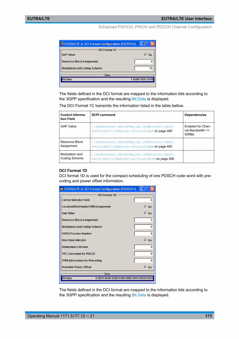
EUTRA/LTE User InterfaceEUTRA/LTE
173Operating Manual 1171.5177.12 ─ 21
The fields defined in the DCI format are mapped to the information bits according tothe 3GPP specification and the resulting Bit Data is displayed.
The DCI Format 1C transmits the information listed in the table bellow.
Control Informa-tion Field
SCPI command Dependencies
GAP Value [:SOURce<hw>]: BB: EUTRa:DL[: SUBF<st0>]: ENCC:PDCCh: EXTC:ITEM<ch0>: DCIConf: GAP on page 489
Enabled for Chan-nel Bandwidth >=50RBs
Resource BlockAssignment
[:SOURce<hw>]: BB: EUTRa:DL[: SUBF<st0>]: ENCC:PDCCh: EXTC:ITEM<ch0>: DCIConf: RBA on page 493
Modulation andCoding Scheme
[:SOURce<hw>]: BB: EUTRa:DL[: SUBF<st0>]: ENCC:PDCCh: EXTC:ITEM<ch0>: DCIConf: MCSR on page 490
DCI Format 1DDCI format 1D is used for the compact scheduling of one PDSCH code word with pre-coding and power offset information.
The fields defined in the DCI format are mapped to the information bits according tothe 3GPP specification and the resulting Bit Data is displayed.
Enhanced PCFICH, PHICH and PDCCH Channel Configuration
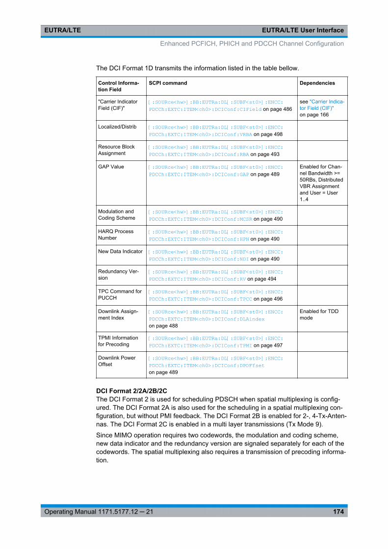
EUTRA/LTE User InterfaceEUTRA/LTE
174Operating Manual 1171.5177.12 ─ 21
The DCI Format 1D transmits the information listed in the table bellow.
Control Informa-tion Field
SCPI command Dependencies
"Carrier IndicatorField (CIF)"
[:SOURce<hw>]: BB: EUTRa:DL[: SUBF<st0>]: ENCC:PDCCh: EXTC:ITEM<ch0>: DCIConf: CIField on page 486
see "Carrier Indica-tor Field (CIF)"on page 166
Localized/Distrib [:SOURce<hw>]: BB: EUTRa:DL[: SUBF<st0>]: ENCC:PDCCh: EXTC:ITEM<ch0>: DCIConf: VRBA on page 498
Resource BlockAssignment
[:SOURce<hw>]: BB: EUTRa:DL[: SUBF<st0>]: ENCC:PDCCh: EXTC:ITEM<ch0>: DCIConf: RBA on page 493
GAP Value [:SOURce<hw>]: BB: EUTRa:DL[: SUBF<st0>]: ENCC:PDCCh: EXTC:ITEM<ch0>: DCIConf: GAP on page 489
Enabled for Chan-nel Bandwidth >=50RBs, DistributedVBR Assignmentand User = User1..4
Modulation andCoding Scheme
[:SOURce<hw>]: BB: EUTRa:DL[: SUBF<st0>]: ENCC:PDCCh: EXTC:ITEM<ch0>: DCIConf: MCSR on page 490
HARQ ProcessNumber
[:SOURce<hw>]: BB: EUTRa:DL[: SUBF<st0>]: ENCC:PDCCh: EXTC:ITEM<ch0>: DCIConf: HPN on page 490
New Data Indicator [:SOURce<hw>]: BB: EUTRa:DL[: SUBF<st0>]: ENCC:PDCCh: EXTC:ITEM<ch0>: DCIConf: NDI on page 490
Redundancy Ver-sion
[:SOURce<hw>]: BB: EUTRa:DL[: SUBF<st0>]: ENCC:PDCCh: EXTC:ITEM<ch0>: DCIConf: RV on page 494
TPC Command forPUCCH
[:SOURce<hw>]: BB: EUTRa:DL[: SUBF<st0>]: ENCC:PDCCh: EXTC:ITEM<ch0>: DCIConf: TPCC on page 496
Downlink Assign-ment Index
[:SOURce<hw>]: BB: EUTRa:DL[: SUBF<st0>]: ENCC:PDCCh: EXTC:ITEM<ch0>: DCIConf: DLAindex on page 488
Enabled for TDDmode
TPMI Informationfor Precoding
[:SOURce<hw>]: BB: EUTRa:DL[: SUBF<st0>]: ENCC:PDCCh: EXTC:ITEM<ch0>: DCIConf: TPMI on page 497
Downlink PowerOffset
[:SOURce<hw>]: BB: EUTRa:DL[: SUBF<st0>]: ENCC:PDCCh: EXTC:ITEM<ch0>: DCIConf: DPOFfset on page 489
DCI Format 2/2A/2B/2CThe DCI Format 2 is used for scheduling PDSCH when spatial multiplexing is config-ured. The DCI Format 2A is also used for the scheduling in a spatial multiplexing con-figuration, but without PMI feedback. The DCI Format 2B is enabled for 2-, 4-Tx-Anten-nas. The DCI Format 2C is enabled in a multi layer transmissions (Tx Mode 9).
Since MIMO operation requires two codewords, the modulation and coding scheme,new data indicator and the redundancy version are signaled separately for each of thecodewords. The spatial multiplexing also requires a transmission of precoding informa-tion.
Enhanced PCFICH, PHICH and PDCCH Channel Configuration
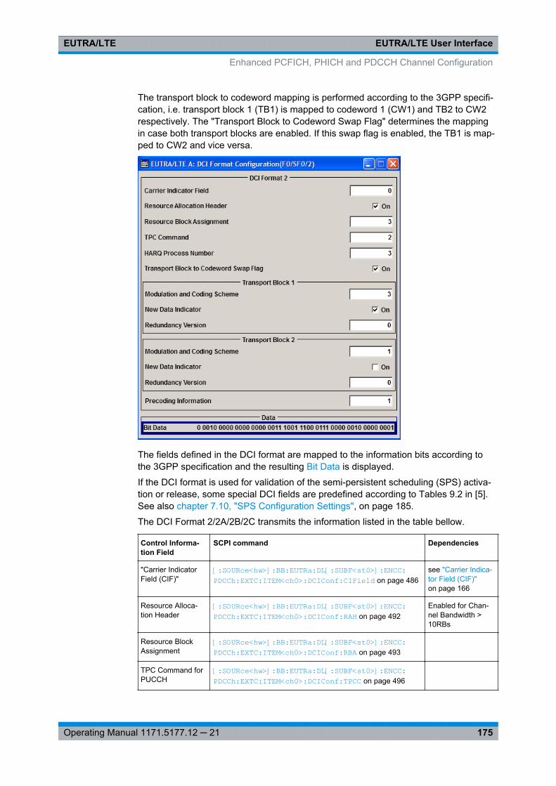
EUTRA/LTE User InterfaceEUTRA/LTE
175Operating Manual 1171.5177.12 ─ 21
The transport block to codeword mapping is performed according to the 3GPP specifi-cation, i.e. transport block 1 (TB1) is mapped to codeword 1 (CW1) and TB2 to CW2respectively. The "Transport Block to Codeword Swap Flag" determines the mappingin case both transport blocks are enabled. If this swap flag is enabled, the TB1 is map-ped to CW2 and vice versa.
The fields defined in the DCI format are mapped to the information bits according tothe 3GPP specification and the resulting Bit Data is displayed.
If the DCI format is used for validation of the semi-persistent scheduling (SPS) activa-tion or release, some special DCI fields are predefined according to Tables 9.2 in [5].See also chapter 7.10, "SPS Configuration Settings", on page 185.
The DCI Format 2/2A/2B/2C transmits the information listed in the table bellow.
Control Informa-tion Field
SCPI command Dependencies
"Carrier IndicatorField (CIF)"
[:SOURce<hw>]: BB: EUTRa:DL[: SUBF<st0>]: ENCC:PDCCh: EXTC:ITEM<ch0>: DCIConf: CIField on page 486
see "Carrier Indica-tor Field (CIF)"on page 166
Resource Alloca-tion Header
[:SOURce<hw>]: BB: EUTRa:DL[: SUBF<st0>]: ENCC:PDCCh: EXTC:ITEM<ch0>: DCIConf: RAH on page 492
Enabled for Chan-nel Bandwidth >10RBs
Resource BlockAssignment
[:SOURce<hw>]: BB: EUTRa:DL[: SUBF<st0>]: ENCC:PDCCh: EXTC:ITEM<ch0>: DCIConf: RBA on page 493
TPC Command forPUCCH
[:SOURce<hw>]: BB: EUTRa:DL[: SUBF<st0>]: ENCC:PDCCh: EXTC:ITEM<ch0>: DCIConf: TPCC on page 496
Enhanced PCFICH, PHICH and PDCCH Channel Configuration
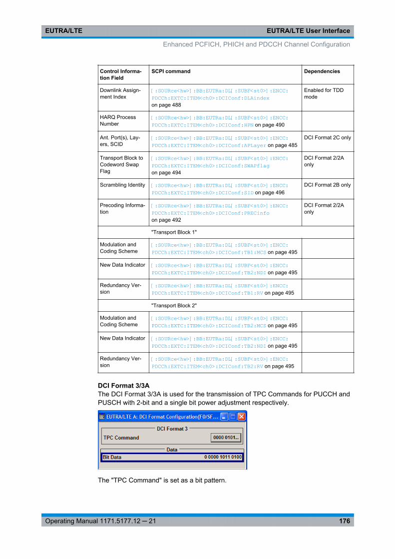
EUTRA/LTE User InterfaceEUTRA/LTE
176Operating Manual 1171.5177.12 ─ 21
Control Informa-tion Field
SCPI command Dependencies
Downlink Assign-ment Index
[:SOURce<hw>]: BB: EUTRa:DL[: SUBF<st0>]: ENCC:PDCCh: EXTC:ITEM<ch0>: DCIConf: DLAindex on page 488
Enabled for TDDmode
HARQ ProcessNumber
[:SOURce<hw>]: BB: EUTRa:DL[: SUBF<st0>]: ENCC:PDCCh: EXTC:ITEM<ch0>: DCIConf: HPN on page 490
Ant. Port(s), Lay-ers, SCID
[:SOURce<hw>]: BB: EUTRa:DL[: SUBF<st0>]: ENCC:PDCCh: EXTC:ITEM<ch0>: DCIConf: APLayer on page 485
DCI Format 2C only
Transport Block toCodeword SwapFlag
[:SOURce<hw>]: BB: EUTRa:DL[: SUBF<st0>]: ENCC:PDCCh: EXTC:ITEM<ch0>: DCIConf: SWAPflag on page 494
DCI Format 2/2Aonly
Scrambling Identity [:SOURce<hw>]: BB: EUTRa:DL[: SUBF<st0>]: ENCC:PDCCh: EXTC:ITEM<ch0>: DCIConf: SID on page 496
DCI Format 2B only
Precoding Informa-tion
[:SOURce<hw>]: BB: EUTRa:DL[: SUBF<st0>]: ENCC:PDCCh: EXTC:ITEM<ch0>: DCIConf: PRECinfo on page 492
DCI Format 2/2Aonly
"Transport Block 1"
Modulation andCoding Scheme
[:SOURce<hw>]: BB: EUTRa:DL[: SUBF<st0>]: ENCC:PDCCh: EXTC:ITEM<ch0>: DCIConf: TB1:MCS on page 495
New Data Indicator [:SOURce<hw>]: BB: EUTRa:DL[: SUBF<st0>]: ENCC:PDCCh: EXTC:ITEM<ch0>: DCIConf: TB2:NDI on page 495
Redundancy Ver-sion
[:SOURce<hw>]: BB: EUTRa:DL[: SUBF<st0>]: ENCC:PDCCh: EXTC:ITEM<ch0>: DCIConf: TB1:RV on page 495
"Transport Block 2"
Modulation andCoding Scheme
[:SOURce<hw>]: BB: EUTRa:DL[: SUBF<st0>]: ENCC:PDCCh: EXTC:ITEM<ch0>: DCIConf: TB2:MCS on page 495
New Data Indicator [:SOURce<hw>]: BB: EUTRa:DL[: SUBF<st0>]: ENCC:PDCCh: EXTC:ITEM<ch0>: DCIConf: TB2:NDI on page 495
Redundancy Ver-sion
[:SOURce<hw>]: BB: EUTRa:DL[: SUBF<st0>]: ENCC:PDCCh: EXTC:ITEM<ch0>: DCIConf: TB2:RV on page 495
DCI Format 3/3AThe DCI Format 3/3A is used for the transmission of TPC Commands for PUCCH andPUSCH with 2-bit and a single bit power adjustment respectively.
The "TPC Command" is set as a bit pattern.
Enhanced PCFICH, PHICH and PDCCH Channel Configuration
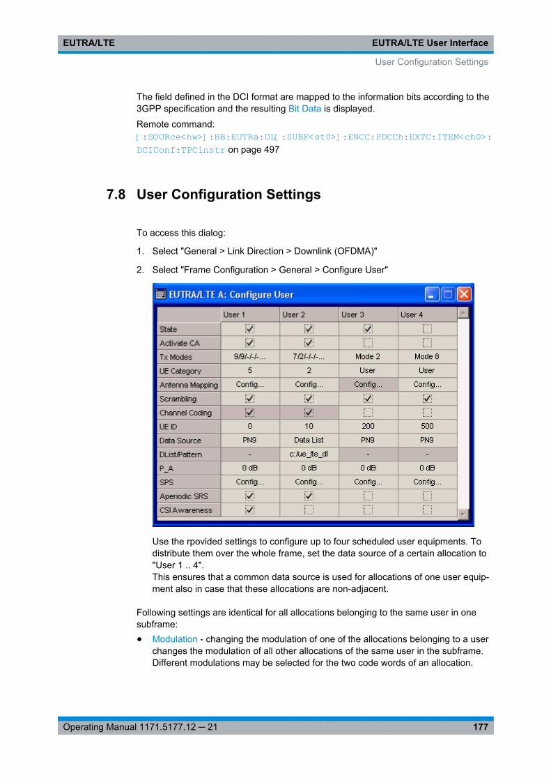
EUTRA/LTE User InterfaceEUTRA/LTE
177Operating Manual 1171.5177.12 ─ 21
The field defined in the DCI format are mapped to the information bits according to the3GPP specification and the resulting Bit Data is displayed.
Remote command: [:SOURce<hw>]: BB:EUTRa: DL[:SUBF<st0>]: ENCC: PDCCh:EXTC: ITEM<ch0>: DCIConf: TPCinstr on page 497
7.8 User Configuration Settings
To access this dialog:
1. Select "General > Link Direction > Downlink (OFDMA)"
2. Select "Frame Configuration > General > Configure User"
Use the rpovided settings to configure up to four scheduled user equipments. Todistribute them over the whole frame, set the data source of a certain allocation to"User 1 .. 4".This ensures that a common data source is used for allocations of one user equip-ment also in case that these allocations are non-adjacent.
Following settings are identical for all allocations belonging to the same user in onesubframe:● Modulation - changing the modulation of one of the allocations belonging to a user
changes the modulation of all other allocations of the same user in the subframe.Different modulations may be selected for the two code words of an allocation.
User Configuration Settings
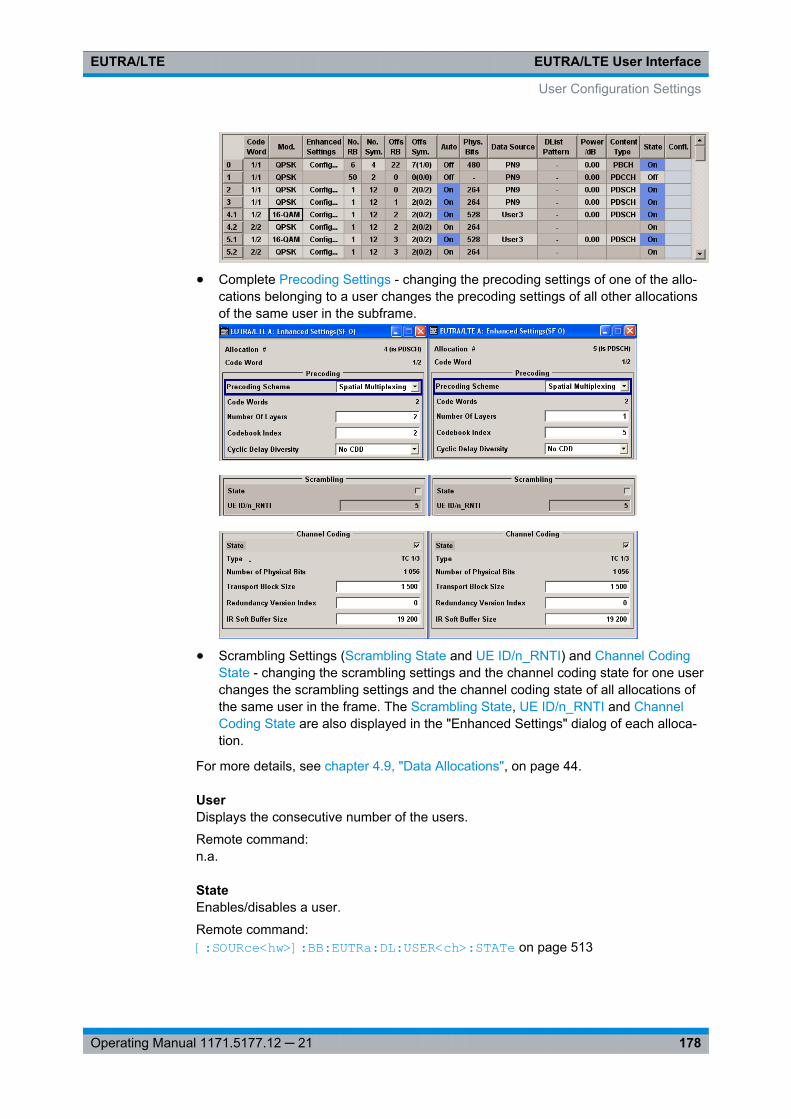
EUTRA/LTE User InterfaceEUTRA/LTE
178Operating Manual 1171.5177.12 ─ 21
● Complete Precoding Settings - changing the precoding settings of one of the allo-cations belonging to a user changes the precoding settings of all other allocationsof the same user in the subframe.
● Scrambling Settings (Scrambling State and UE ID/n_RNTI) and Channel CodingState - changing the scrambling settings and the channel coding state for one userchanges the scrambling settings and the channel coding state of all allocations ofthe same user in the frame. The Scrambling State, UE ID/n_RNTI and ChannelCoding State are also displayed in the "Enhanced Settings" dialog of each alloca-tion.
For more details, see chapter 4.9, "Data Allocations", on page 44.
UserDisplays the consecutive number of the users.
Remote command: n.a.
StateEnables/disables a user.
Remote command: [:SOURce<hw>]: BB: EUTRa:DL: USER<ch>:STATe on page 513
User Configuration Settings
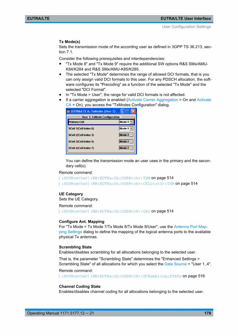
EUTRA/LTE User InterfaceEUTRA/LTE
179Operating Manual 1171.5177.12 ─ 21
Tx Mode(s)Sets the transmission mode of the according user as defined in 3GPP TS 36.213, sec-tion 7.1.
Consider the following prerequisites and interdependencies:● "Tx Mode 8" and "Tx Mode 9" require the additional SW options R&S SMx/AMU-
K84/K284 and R&S SMx/AMU-K85/K285.● The selected "Tx Mode" determines the range of allowed DCI formats, that is you
can only assign valid DCI formats to this user. For any PDSCH allocation, the soft-ware configures its "Precoding" as a function of the selected "Tx Mode" and theselected "DCI Format".
● In "Tx Mode > User", the range for valid DCI formats is not affected.● If a carrier aggregation is enabled (Activate Carrier Aggregation = On and Activate
CA = On), you access the "TxModes Configuration" dialog.
You can define the transmission mode an user uses in the primary and the secon-dary cell(s).
Remote command: [:SOURce<hw>]: BB: EUTRa:DL: USER<ch>:TXM on page 514[:SOURce<hw>]: BB: EUTRa:DL: USER<ch>:CELL<st0>: TXM on page 514
UE CategorySets the UE Category.
Remote command: [:SOURce<hw>]: BB:EUTRa: DL:USER<ch>: UEC on page 514
Configure Ant. MappingFor "Tx Mode = Tx Mode 7/Tx Mode 8/Tx Mode 9/User", use the Antenna Port Map-ping Settings dialog to define the mapping of the logical antenna ports to the availablephysical Tx antennas.
Scrambling StateEnables/disables scrambling for all allocations belonging to the selected user.
That is, the parameter "Scrambling State" determines the "Enhanced Settings >Scrambling State" of all allocations for which you select the Data Source = "User 1..4".
Remote command: [:SOURce<hw>]: BB: EUTRa:DL: USER<ch>:SCRambling: STATe on page 516
Channel Coding StateEnables/disables channel coding for all allocations belonging to the selected user.
User Configuration Settings
EUTRA/LTE User InterfaceEUTRA/LTE
180Operating Manual 1171.5177.12 ─ 21
That is, the parameter "Channel Coding State" determines the "Enhanced Settings >Channel Coding State" of all allocations for which you select the Data Source = "User1..4".
Remote command: [:SOURce<hw>]: BB:EUTRa: DL:USER<ch>: CCODing: STATe on page 517
UE IDSets the user equipment ID.
The software uses this UE ID for the generation of the scrambling sequence for theallocations, for which you select the DL Frame Configuration Settings > AllocationTable > Data Source = "User 1..4".
Remote command: [:SOURce<hw>]: BB:EUTRa: DL:USER<ch>: UEID on page 517
Data Source, DList/PatternSelects the data source for the selected user.
The following standard data sources are available:● "All 0, All 1"
An internally generated sequence containing 0 data or 1 data.● "PNxx"
An internally generated pseudo-random noise sequence.● "Pattern"
An internally generated sequence according to a bit pattern.Use the "Pattern" box to define the bit pattern.
● "Data List/Select DList"A binary data from a data list, internally or externally generated.Select "Select DList" to access the standard "Select List" dialog.– Select the "Select Data List > navigate to the list file *.dm_iqd > Select" to
select an existing data list.– Use the "New" and "Edit" functions to create internally new data list or to edit
an existing one.– Use the standard "File Manager" function to transfer external data lists to the
instrument.See also "Main Dialog > Data List Management".
Remote command: [:SOURce<hw>]: BB:EUTRa: DL:USER<ch>: DATA on page 517[:SOURce<hw>]: BB:EUTRa: DL:USER<ch>: DSELect on page 518[:SOURce<hw>]: BB:EUTRa: DL:USER<ch>: PATTern on page 518
P_ASets PDSCH power factor according to 3GPP TS 36.213, chapter 5.2.
This power value is applied to all allocations that belong to the corresponding user.The power of an allocation is additionally determined by the parameter "PDSCHScheduling Mode". In a normal operation, the power values in the allocation table areconfigurable parameters. In the"Auto/DCI" mode however, the power value is fixed andcannot be adjusted.
User Configuration Settings
EUTRA/LTE User InterfaceEUTRA/LTE
181Operating Manual 1171.5177.12 ─ 21
For the DCI format 1D, an additional level offset has to be considered.
Remote command: [:SOURce<hw>]: BB:EUTRa: DL:USER<ch>: PA on page 518
SPSAccesses the SPS Configuration Settings dialog to configure a semi-persistansescheduling for the selected user.
Aperiodic SRSEnabes/disables an aperiodic transmission of SRS for the selected user.
The aperiodic SRS transmition is a single (one-shot) transmition. Use this parameteras the required SRS trigger for the PDSCH for which you select the DL Frame Configu-ration Settings > Allocation Table > Data Source = "User 1..4".
The SRS are transmitted wihtin the last symbol of a subframe. Use the parameter DCIFormat 1A > "SRS Request" to select on of the three SRS parameter sets.
Tip: Use the SRS Structure settings and the User Equipment Configuration to config-ure the periodic SRS transmission.
Remote command: [:SOURce<hw>]: BB:EUTRa:DL: USER<ch>: ASRS:STATe on page 519
Activate CARequires software option R&S SMx/AMU-K85 (LTE-A Rel. 10)
Enables/disables carrier aggregation for the selected user.
If Activate Carrier Aggregation is enabled, carrier aggregation is activated automati-cally for all users, but can be deactivated afterwards.
Remote command: [: SOURce<hw>]: BB:EUTRa: DL:USER<ch>: CA:STATe on page 514
CSI AwarenessEnables/disables the CSI awareness for the selected user, i.e. informs the UE that aCSI-RS are transmitted. See also chapter 3.1.5.5, "CSI reference signals", on page 26.
Remote command: [:SOURce<hw>]: BB: EUTRa:DL:USER<ch>: CAW: STATe on page 519
7.9 Antenna Port Mapping Settings
The 3GPP standard defines the different antenna ports for transmission in differenttransmission modes (TM, also "TxMode") and for the transmission of different refer-ence signals, see table 3-3 and chapter 3.1.5, "Downlink Reference Signal Structureand Cell Search", on page 20.
Antenna Port Mapping Settings
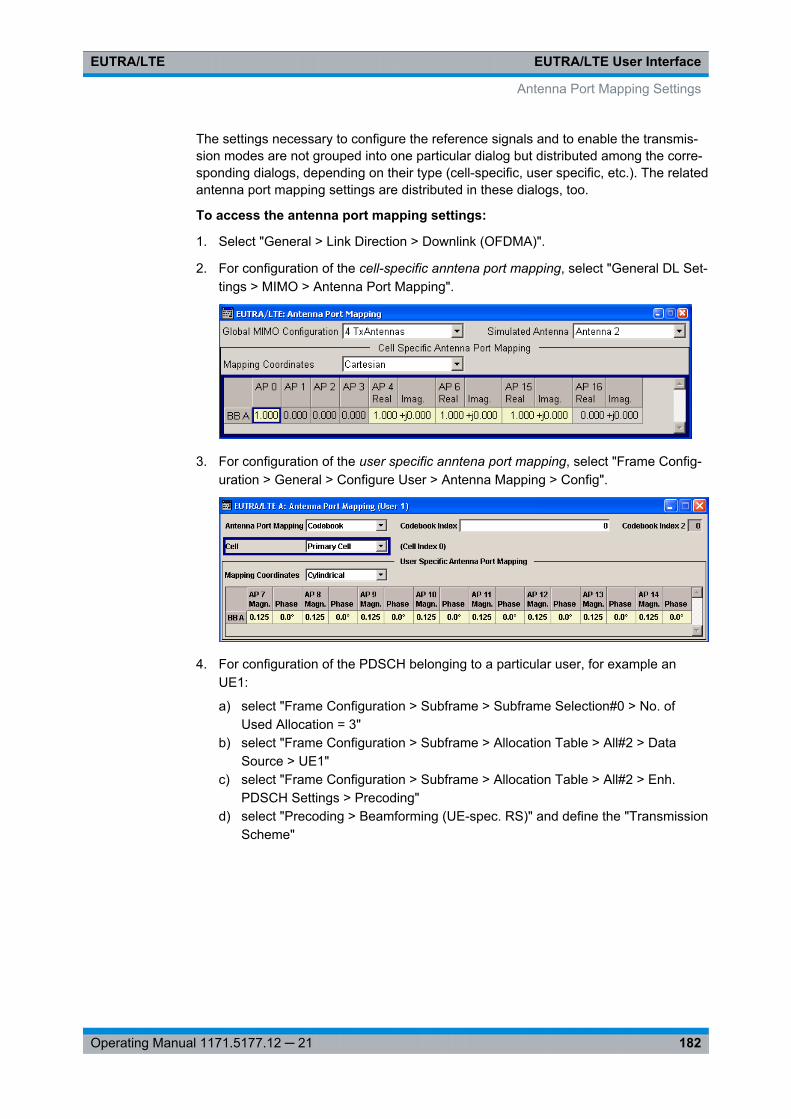
EUTRA/LTE User InterfaceEUTRA/LTE
182Operating Manual 1171.5177.12 ─ 21
The settings necessary to configure the reference signals and to enable the transmis-sion modes are not grouped into one particular dialog but distributed among the corre-sponding dialogs, depending on their type (cell-specific, user specific, etc.). The relatedantenna port mapping settings are distributed in these dialogs, too.
To access the antenna port mapping settings:
1. Select "General > Link Direction > Downlink (OFDMA)".
2. For configuration of the cell-specific anntena port mapping, select "General DL Set-tings > MIMO > Antenna Port Mapping".
3. For configuration of the user specific anntena port mapping, select "Frame Config-uration > General > Configure User > Antenna Mapping > Config".
4. For configuration of the PDSCH belonging to a particular user, for example anUE1:
a) select "Frame Configuration > Subframe > Subframe Selection#0 > No. ofUsed Allocation = 3"
b) select "Frame Configuration > Subframe > Allocation Table > All#2 > DataSource > UE1"
c) select "Frame Configuration > Subframe > Allocation Table > All#2 > Enh.PDSCH Settings > Precoding"
d) select "Precoding > Beamforming (UE-spec. RS)" and define the "TransmissionScheme"
Antenna Port Mapping Settings
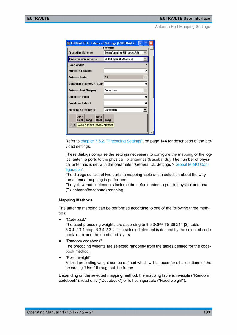
EUTRA/LTE User InterfaceEUTRA/LTE
183Operating Manual 1171.5177.12 ─ 21
Refer to chapter 7.6.2, "Precoding Settings", on page 144 for description of the pro-vided settings.
These dialogs comprise the settings necessary to configure the mapping of the log-ical antenna ports to the physical Tx antennas (Basebands). The number of physi-cal antennas is set with the parameter "General DL Settings > Global MIMO Con-figuration".The dialogs consist of two parts, a mapping table and a selection about the waythe antenna mapping is performed.The yellow matrix elements indicate the default antenna port to physical antenna(Tx antenna/baseband) mapping.
Mapping Methods
The antenna mapping can be performed according to one of the following three meth-ods:● "Codebook"
The used precoding weights are according to the 3GPP TS 36.211 [3], table6.3.4.2.3-1 resp. 6.3.4.2.3-2. The selected element is defined by the selected code-book index and the number of layers.
● "Random codebook"The precoding weights are selected randomly from the tables defined for the code-book method.
● "Fixed weight"A fixed precoding weight can be defined which will be used for all allocations of theaccording “User” throughout the frame.
Depending on the selected mapping method, the mapping table is invisible ("Randomcodebook"), read-only ("Codebook") or full configurable ("Fixed weight").
Antenna Port Mapping Settings
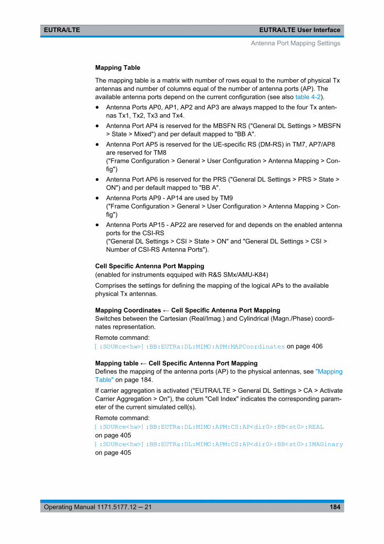
EUTRA/LTE User InterfaceEUTRA/LTE
184Operating Manual 1171.5177.12 ─ 21
Mapping Table
The mapping table is a matrix with number of rows equal to the number of physical Txantennas and number of columns equal of the number of antenna ports (AP). Theavailable antenna ports depend on the current configuration (see also table 4-2).● Antenna Ports AP0, AP1, AP2 and AP3 are always mapped to the four Tx anten-
nas Tx1, Tx2, Tx3 and Tx4.● Antenna Port AP4 is reserved for the MBSFN RS ("General DL Settings > MBSFN
> State > Mixed") and per default mapped to "BB A".● Antenna Port AP5 is reserved for the UE-specific RS (DM-RS) in TM7, AP7/AP8
are reserved for TM8("Frame Configuration > General > User Configuration > Antenna Mapping > Con-fig")
● Antenna Port AP6 is reserved for the PRS ("General DL Settings > PRS > State >ON") and per default mapped to "BB A".
● Antenna Ports AP9 - AP14 are used by TM9("Frame Configuration > General > User Configuration > Antenna Mapping > Con-fig")
● Antenna Ports AP15 - AP22 are reserved for and depends on the enabled antennaports for the CSI-RS("General DL Settings > CSI > State > ON" and "General DL Settings > CSI >Number of CSI-RS Antenna Ports").
Cell Specific Antenna Port Mapping(enabled for instruments eqquiped with R&S SMx/AMU-K84)
Comprises the settings for defining the mapping of the logical APs to the availablephysical Tx antennas.
Mapping Coordinates ← Cell Specific Antenna Port MappingSwitches between the Cartesian (Real/Imag.) and Cylindrical (Magn./Phase) coordi-nates representation.
Remote command: [:SOURce<hw>]: BB:EUTRa: DL:MIMO:APM: MAPCoordinates on page 406
Mapping table ← Cell Specific Antenna Port MappingDefines the mapping of the antenna ports (AP) to the physical antennas, see "MappingTable" on page 184.
If carrier aggregation is activated ("EUTRA/LTE > General DL Settings > CA > ActivateCarrier Aggregation > On"), the colum "Cell Index" indicates the corresponding param-eter of the current simulated cell(s).
Remote command: [:SOURce<hw>]: BB:EUTRa: DL:MIMO: APM:CS:AP<dir0>: BB<st0>: REALon page 405[:SOURce<hw>]: BB:EUTRa: DL:MIMO: APM:CS:AP<dir0>: BB<st0>: IMAGinary on page 405
Antenna Port Mapping Settings
EUTRA/LTE User InterfaceEUTRA/LTE
185Operating Manual 1171.5177.12 ─ 21
User Specific Anntena Port MappingComprises the settings for defining the mapping of the logical APs to the availablephysical Tx antennas.
Antenna Port Mapping ← User Specific Anntena Port MappingDefines the antenna port mapping method, see Mapping Methods.
Remote command: [:SOURce<hw>]: BB:EUTRa:DL: USER<ch>: APM:MODE on page 515
Codebook Index/Codebook Index 2 ← User Specific Anntena Port MappingSets the codebook index for mapping mode Codebook.
Remote command: [:SOURce<hw>]: BB:EUTRa: DL:USER<ch>: APM:CBINdex[<dir>] on page 515
Cell ← User Specific Anntena Port MappingIndicates the cell the antenna poert mapping is related to, if a carrier aggregation isenabled (Activate Carrier Aggregation = On and Activate CA = On).
Displayed are the primary and the secondary cell(s) whit their cell index, as configuredwith the parameter Cell Index.
Remote command: n.a.
Mapping Coordinates ← User Specific Anntena Port MappingSwitches between the Cartesian (Real/Imag.) and Cylindrical (Magn./Phase) coordi-nates representation.
Remote command: [:SOURce<hw>]: BB:EUTRa:DL: USER<ch>: APM:MAPCoordinates on page 515
Mapping table ← User Specific Anntena Port MappingDefines the mapping of the antenna ports (AP) to the physical antennas, see also"Mapping Table" on page 184.
Remote command: [:SOURce<hw>]: BB: EUTRa:DL:USER<ch>: APM: AP<dir0>: BB<st0>:REAL on page 516[:SOURce<hw>]: BB: EUTRa:DL:USER<ch>: APM: AP<dir0>: BB<st0>:IMAGinary on page 516
7.10 SPS Configuration Settings
To access this dialog:
1. Select "General > Link Direction > Downlink (OFDMA)"
2. Select "Frame Configuration > General > Configure User"
SPS Configuration Settings
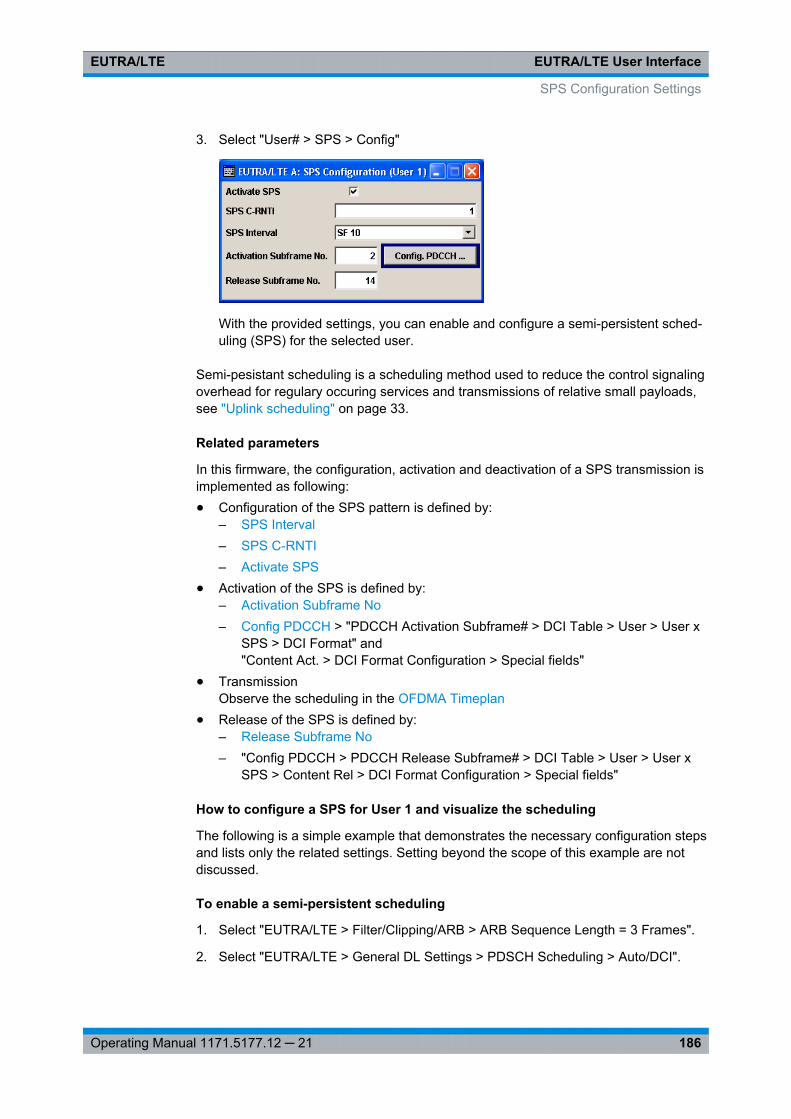
EUTRA/LTE User InterfaceEUTRA/LTE
186Operating Manual 1171.5177.12 ─ 21
3. Select "User# > SPS > Config"
With the provided settings, you can enable and configure a semi-persistent sched-uling (SPS) for the selected user.
Semi-pesistant scheduling is a scheduling method used to reduce the control signalingoverhead for regulary occuring services and transmissions of relative small payloads,see "Uplink scheduling" on page 33.
Related parameters
In this firmware, the configuration, activation and deactivation of a SPS transmission isimplemented as following:● Configuration of the SPS pattern is defined by:
– SPS Interval– SPS C-RNTI– Activate SPS
● Activation of the SPS is defined by:– Activation Subframe No– Config PDCCH > "PDCCH Activation Subframe# > DCI Table > User > User x
SPS > DCI Format" and"Content Act. > DCI Format Configuration > Special fields"
● TransmissionObserve the scheduling in the OFDMA Timeplan
● Release of the SPS is defined by:– Release Subframe No– "Config PDCCH > PDCCH Release Subframe# > DCI Table > User > User x
SPS > Content Rel > DCI Format Configuration > Special fields"
How to configure a SPS for User 1 and visualize the scheduling
The following is a simple example that demonstrates the necessary configuration stepsand lists only the related settings. Setting beyond the scope of this example are notdiscussed.
To enable a semi-persistent scheduling
1. Select "EUTRA/LTE > Filter/Clipping/ARB > ARB Sequence Length = 3 Frames".
2. Select "EUTRA/LTE > General DL Settings > PDSCH Scheduling > Auto/DCI".
SPS Configuration Settings
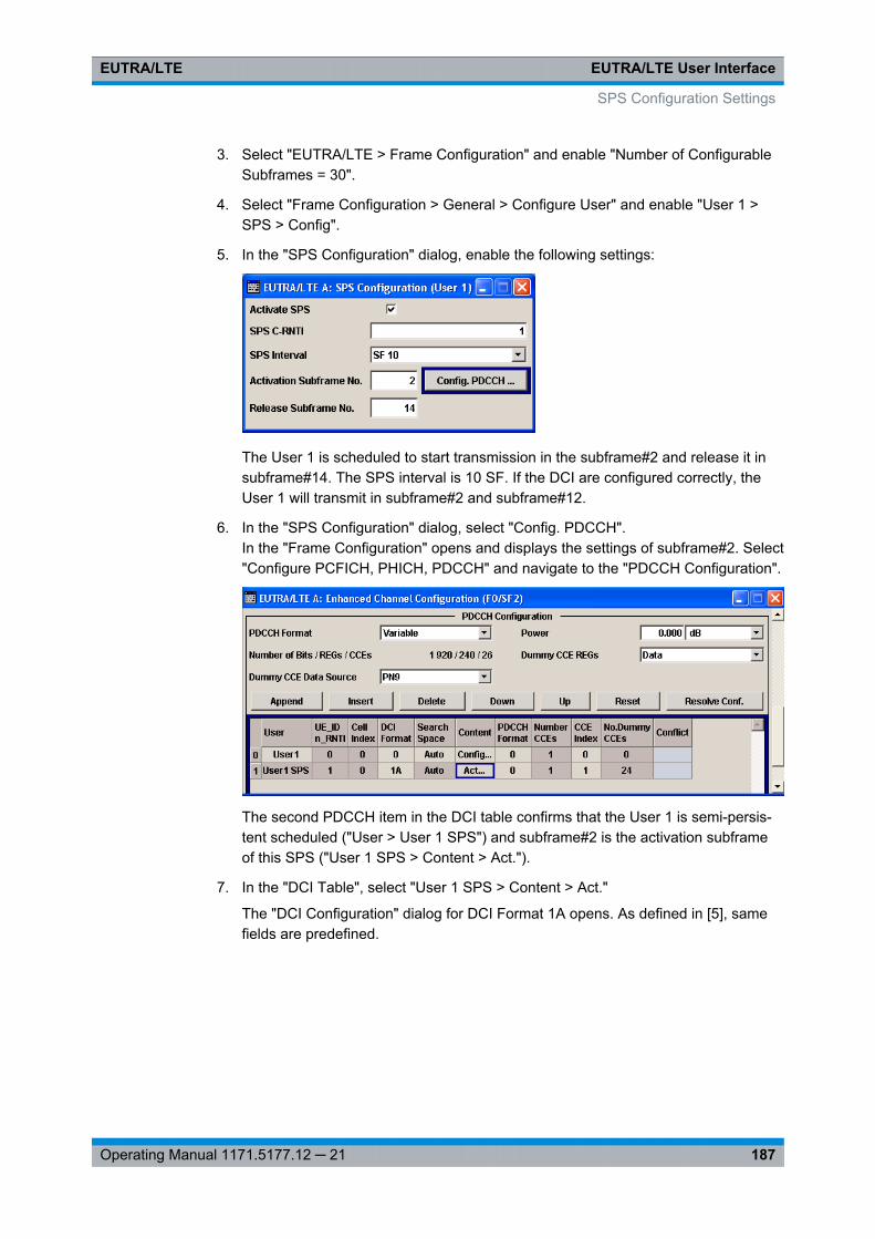
EUTRA/LTE User InterfaceEUTRA/LTE
187Operating Manual 1171.5177.12 ─ 21
3. Select "EUTRA/LTE > Frame Configuration" and enable "Number of ConfigurableSubframes = 30".
4. Select "Frame Configuration > General > Configure User" and enable "User 1 >SPS > Config".
5. In the "SPS Configuration" dialog, enable the following settings:
The User 1 is scheduled to start transmission in the subframe#2 and release it insubframe#14. The SPS interval is 10 SF. If the DCI are configured correctly, theUser 1 will transmit in subframe#2 and subframe#12.
6. In the "SPS Configuration" dialog, select "Config. PDCCH".In the "Frame Configuration" opens and displays the settings of subframe#2. Select"Configure PCFICH, PHICH, PDCCH" and navigate to the "PDCCH Configuration".
The second PDCCH item in the DCI table confirms that the User 1 is semi-persis-tent scheduled ("User > User 1 SPS") and subframe#2 is the activation subframeof this SPS ("User 1 SPS > Content > Act.").
7. In the "DCI Table", select "User 1 SPS > Content > Act."
The "DCI Configuration" dialog for DCI Format 1A opens. As defined in [5], samefields are predefined.
SPS Configuration Settings
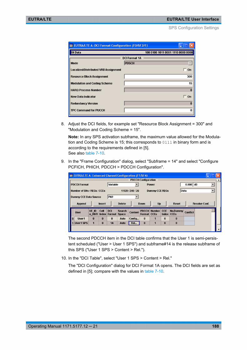
EUTRA/LTE User InterfaceEUTRA/LTE
188Operating Manual 1171.5177.12 ─ 21
8. Adjust the DCI fields, for example set "Resource Block Assignment = 300" and"Modulation and Coding Scheme = 15".
Note: In any SPS activation subframe, the maximum value allowed for the Modula-tion and Coding Scheme is 15; this corresponds to 0111 in binary form and isaccording to the requirements defined in [5].See also table 7-10.
9. In the "Frame Configuration" dialog, select "Subframe = 14" and select "ConfigurePCFICH, PHICH, PDCCH > PDCCH Configuration".
The second PDCCH item in the DCI table confirms that the User 1 is semi-persis-tent scheduled ("User > User 1 SPS") and subframe#14 is the release subframe ofthis SPS ("User 1 SPS > Content > Rel.").
10. In the "DCI Table", select "User 1 SPS > Content > Rel."
The "DCI Configuration" dialog for DCI Format 1A opens. The DCI fields are set asdefined in [5]; compare with the values in table 7-10.
SPS Configuration Settings
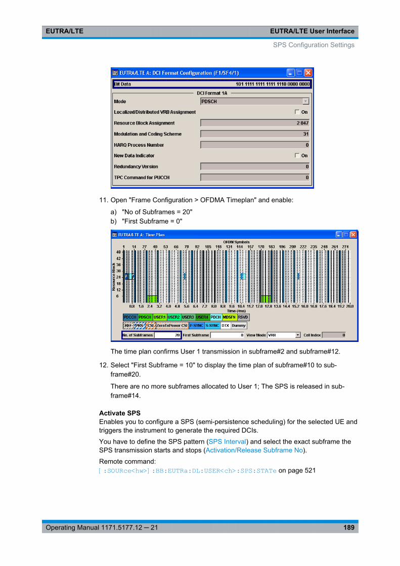
EUTRA/LTE User InterfaceEUTRA/LTE
189Operating Manual 1171.5177.12 ─ 21
11. Open "Frame Configuration > OFDMA Timeplan" and enable:
a) "No of Subframes = 20"b) "First Subframe = 0"
The time plan confirms User 1 transmission in subframe#2 and subframe#12.
12. Select "First Subframe = 10" to display the time plan of subframe#10 to sub-frame#20.
There are no more subframes allocated to User 1; The SPS is released in sub-frame#14.
Activate SPSEnables you to configure a SPS (semi-persistence scheduling) for the selected UE andtriggers the instrument to generate the required DCIs.
You have to define the SPS pattern (SPS Interval) and select the exact subframe theSPS transmission starts and stops (Activation/Release Subframe No).
Remote command: [:SOURce<hw>]: BB:EUTRa: DL:USER<ch>: SPS:STATe on page 521
SPS Configuration Settings
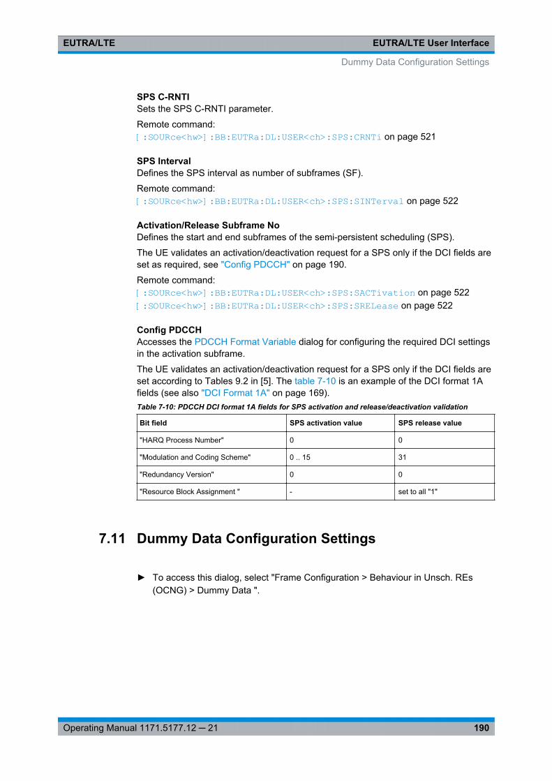
EUTRA/LTE User InterfaceEUTRA/LTE
190Operating Manual 1171.5177.12 ─ 21
SPS C-RNTISets the SPS C-RNTI parameter.
Remote command: [:SOURce<hw>]: BB:EUTRa: DL:USER<ch>: SPS:CRNTi on page 521
SPS IntervalDefines the SPS interval as number of subframes (SF).
Remote command: [:SOURce<hw>]: BB:EUTRa: DL:USER<ch>: SPS:SINTerval on page 522
Activation/Release Subframe NoDefines the start and end subframes of the semi-persistent scheduling (SPS).
The UE validates an activation/deactivation request for a SPS only if the DCI fields areset as required, see "Config PDCCH" on page 190.
Remote command: [:SOURce<hw>]: BB: EUTRa:DL: USER<ch>:SPS: SACTivation on page 522[:SOURce<hw>]: BB: EUTRa:DL: USER<ch>:SPS: SRELease on page 522
Config PDCCHAccesses the PDCCH Format Variable dialog for configuring the required DCI settingsin the activation subframe.
The UE validates an activation/deactivation request for a SPS only if the DCI fields areset according to Tables 9.2 in [5]. The table 7-10 is an example of the DCI format 1Afields (see also "DCI Format 1A" on page 169).Table 7-10: PDCCH DCI format 1A fields for SPS activation and release/deactivation validation
Bit field SPS activation value SPS release value
"HARQ Process Number" 0 0
"Modulation and Coding Scheme" 0 .. 15 31
"Redundancy Version" 0 0
"Resource Block Assignment " - set to all "1"
7.11 Dummy Data Configuration Settings
► To access this dialog, select "Frame Configuration > Behaviour in Unsch. REs(OCNG) > Dummy Data ".
Dummy Data Configuration Settings
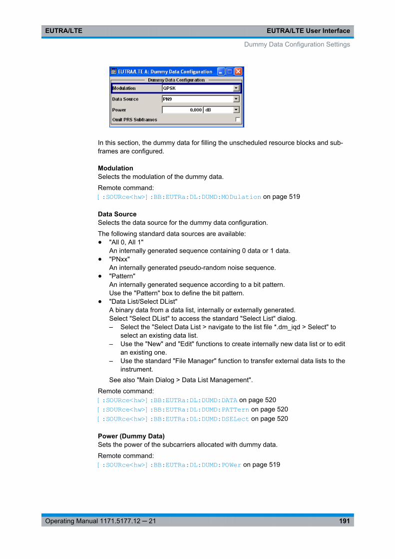
EUTRA/LTE User InterfaceEUTRA/LTE
191Operating Manual 1171.5177.12 ─ 21
In this section, the dummy data for filling the unscheduled resource blocks and sub-frames are configured.
ModulationSelects the modulation of the dummy data.
Remote command: [:SOURce<hw>]: BB: EUTRa:DL: DUMD:MODulation on page 519
Data SourceSelects the data source for the dummy data configuration.
The following standard data sources are available:● "All 0, All 1"
An internally generated sequence containing 0 data or 1 data.● "PNxx"
An internally generated pseudo-random noise sequence.● "Pattern"
An internally generated sequence according to a bit pattern.Use the "Pattern" box to define the bit pattern.
● "Data List/Select DList"A binary data from a data list, internally or externally generated.Select "Select DList" to access the standard "Select List" dialog.– Select the "Select Data List > navigate to the list file *.dm_iqd > Select" to
select an existing data list.– Use the "New" and "Edit" functions to create internally new data list or to edit
an existing one.– Use the standard "File Manager" function to transfer external data lists to the
instrument.See also "Main Dialog > Data List Management".
Remote command: [:SOURce<hw>]: BB:EUTRa: DL:DUMD: DATA on page 520[:SOURce<hw>]: BB:EUTRa: DL:DUMD: PATTern on page 520[:SOURce<hw>]: BB:EUTRa: DL:DUMD: DSELect on page 520
Power (Dummy Data)Sets the power of the subcarriers allocated with dummy data.
Remote command: [:SOURce<hw>]: BB: EUTRa:DL:DUMD: POWer on page 519
Dummy Data Configuration Settings
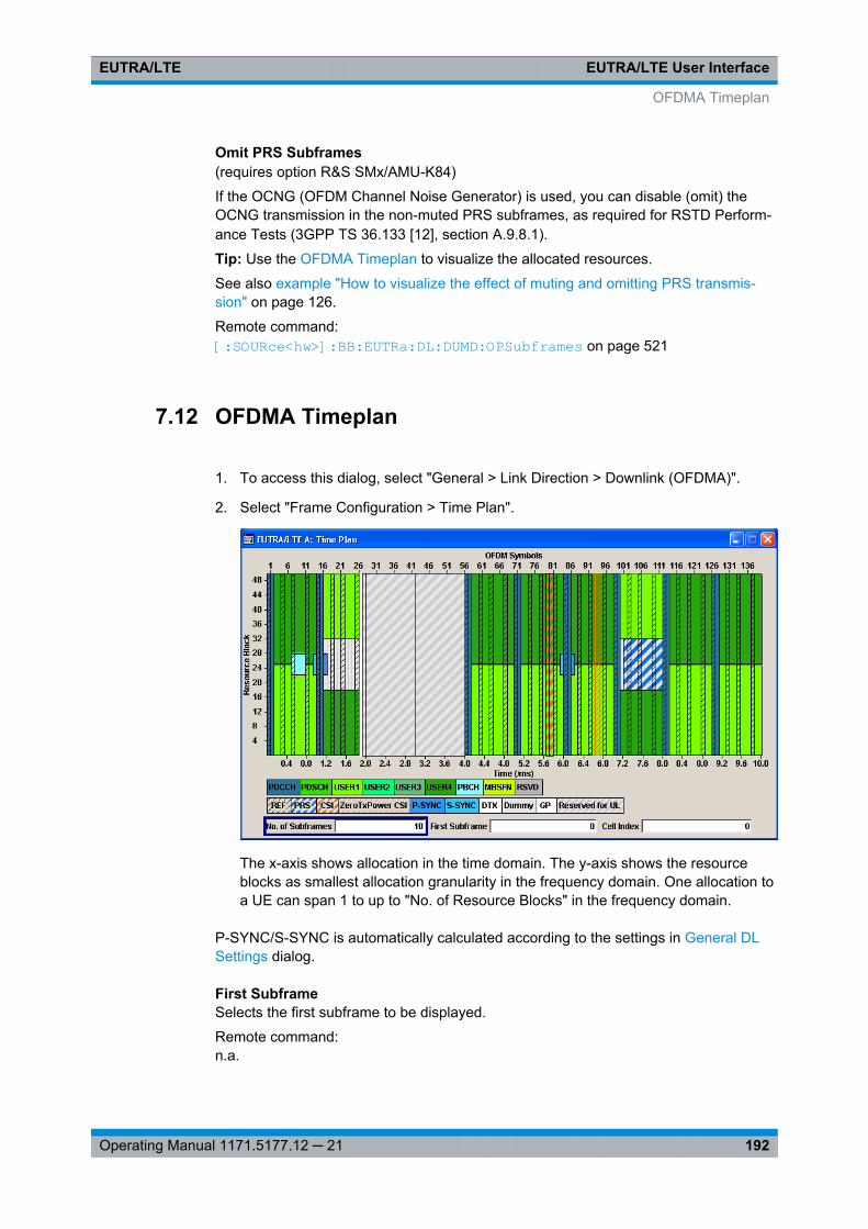
EUTRA/LTE User InterfaceEUTRA/LTE
192Operating Manual 1171.5177.12 ─ 21
Omit PRS Subframes(requires option R&S SMx/AMU-K84)
If the OCNG (OFDM Channel Noise Generator) is used, you can disable (omit) theOCNG transmission in the non-muted PRS subframes, as required for RSTD Perform-ance Tests (3GPP TS 36.133 [12], section A.9.8.1).
Tip: Use the OFDMA Timeplan to visualize the allocated resources.
See also example "How to visualize the effect of muting and omitting PRS transmis-sion" on page 126.
Remote command: [:SOURce<hw>]: BB: EUTRa:DL:DUMD: OPSubframes on page 521
7.12 OFDMA Timeplan
1. To access this dialog, select "General > Link Direction > Downlink (OFDMA)".
2. Select "Frame Configuration > Time Plan".
The x-axis shows allocation in the time domain. The y-axis shows the resourceblocks as smallest allocation granularity in the frequency domain. One allocation toa UE can span 1 to up to "No. of Resource Blocks" in the frequency domain.
P-SYNC/S-SYNC is automatically calculated according to the settings in General DLSettings dialog.
First SubframeSelects the first subframe to be displayed.
Remote command: n.a.
OFDMA Timeplan
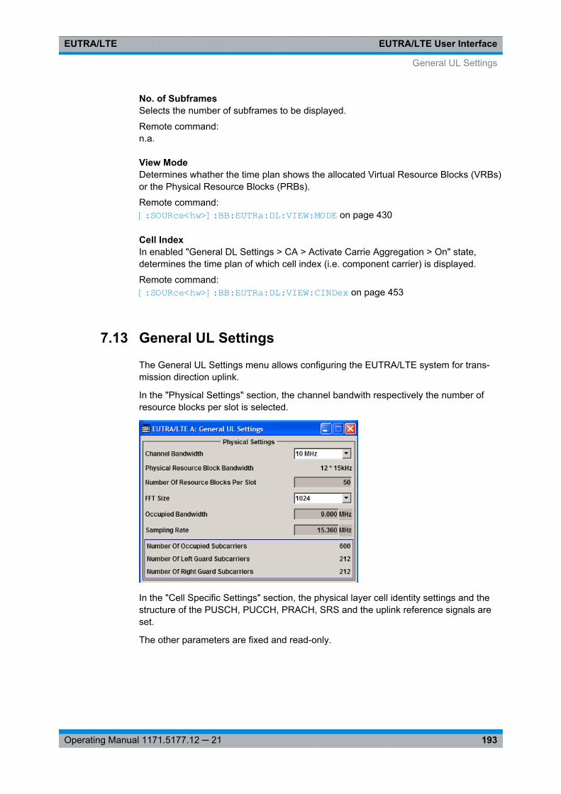
EUTRA/LTE User InterfaceEUTRA/LTE
193Operating Manual 1171.5177.12 ─ 21
No. of SubframesSelects the number of subframes to be displayed.
Remote command: n.a.
View ModeDetermines whather the time plan shows the allocated Virtual Resource Blocks (VRBs)or the Physical Resource Blocks (PRBs).
Remote command: [:SOURce<hw>]: BB:EUTRa:DL: VIEW:MODE on page 430
Cell IndexIn enabled "General DL Settings > CA > Activate Carrie Aggregation > On" state,determines the time plan of which cell index (i.e. component carrier) is displayed.
Remote command: [:SOURce<hw>]: BB:EUTRa: DL:VIEW: CINDex on page 453
7.13 General UL Settings
The General UL Settings menu allows configuring the EUTRA/LTE system for trans-mission direction uplink.
In the "Physical Settings" section, the channel bandwith respectively the number ofresource blocks per slot is selected.
In the "Cell Specific Settings" section, the physical layer cell identity settings and thestructure of the PUSCH, PUCCH, PRACH, SRS and the uplink reference signals areset.
The other parameters are fixed and read-only.
General UL Settings
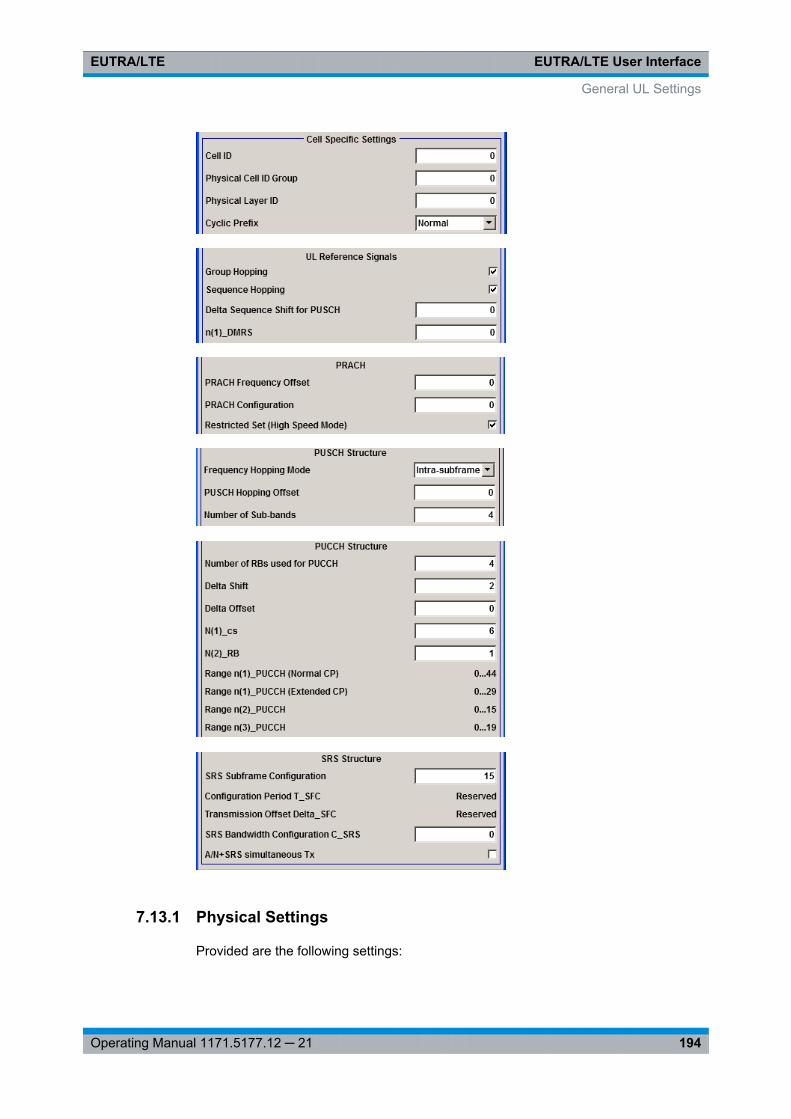
EUTRA/LTE User InterfaceEUTRA/LTE
194Operating Manual 1171.5177.12 ─ 21
7.13.1 Physical Settings
Provided are the following settings:
General UL Settings
EUTRA/LTE User InterfaceEUTRA/LTE
195Operating Manual 1171.5177.12 ─ 21
Channel Bandwidth (UL)Sets the channel bandwidth of the EUTRA/LTE system.
Although the 3GPP specification bases on bandwidth agonistic layer 1 and channelbandwidth is determined by specifying the desired number of resource blocks, the cur-rent EUTRA standardization focuses on six bandwidths (1.4, 3, 5, 10, 15 and 20 MHz).
For backward compatibility with previous version of the implementation, this parameterallows the flexibility to choose, whether a user defined bandwidth or one of the pre-defined channel bandwidths is used.
If a pre-defined channel bandwidth is selected; the actual "Number of Resource BlocksPer Slot" is internally calculated for the selected "Channel Bandwidth" and "PhysicalResource Block Bandwidth".
The sampling rate, occupied bandwidth and FFT size are therefore determined by theparameter "Number of Resource Blocks Per Slot". If required, the FFT Size can beadjusted.
See also table 4-1 for an overview ot this cross-reference between the parameters.
Remote command: [:SOURce<hw>]: BB:EUTRa: UL:BW on page 417
Physical Resource Block Bandwidth (UL)Displays the bandwidth of one physical resource block.
Note: In this release, this value is fixed to 12 x 15 kHz.
Remote command: n.a.
Number of Resource Blocks Per Slot (UL)This parameter determines the channel bandwidth.
If the parameter "Channel Bandwidth" is set to one of the pre-defined channel band-widths (1.4, 3, 5, 10, 15 or 20 MHz), the value "Number of Resource Blocks Per Slot" isread only and is automatically set according to the selected channel bandwidth and"Physical Resource Block Bandwidth".
If a user defined channel bandwidth is selected, the parameters "Number of ResourceBlocks Per Slot" and "Physical Resource Blocks Bandwidth" determine the actualchannel bandwidth.
The sampling rate and the occupied bandwidth are determined by the parameter"Number of Resource Blocks Per Slot". If required, the FFT Size can be adjusted.
See also table 4-1 for an overview ot this cross-reference between the parameters.
Remote command: [:SOURce<hw>]: BB: EUTRa:UL: NORB on page 418
FFT Size (UL)Sets the FFT (Fast Fourier Transformation) size. The available values depend on theselected "Number of Resource Blocks Per Slot".
See also table 4-1 for an overview ot this cross-reference between the parameters.
Remote command: [:SOURce<hw>]: BB:EUTRa: UL:FFT on page 418
General UL Settings
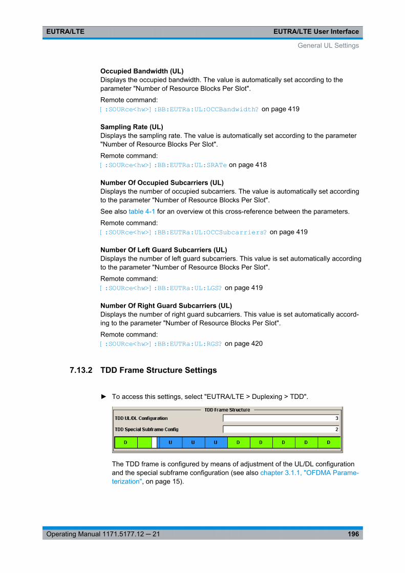
EUTRA/LTE User InterfaceEUTRA/LTE
196Operating Manual 1171.5177.12 ─ 21
Occupied Bandwidth (UL)Displays the occupied bandwidth. The value is automatically set according to theparameter "Number of Resource Blocks Per Slot".
Remote command: [:SOURce<hw>]: BB: EUTRa:UL:OCCBandwidth? on page 419
Sampling Rate (UL)Displays the sampling rate. The value is automatically set according to the parameter"Number of Resource Blocks Per Slot".
Remote command: [:SOURce<hw>]: BB:EUTRa:UL: SRATe on page 418
Number Of Occupied Subcarriers (UL)Displays the number of occupied subcarriers. The value is automatically set accordingto the parameter "Number of Resource Blocks Per Slot".
See also table 4-1 for an overview ot this cross-reference between the parameters.
Remote command: [: SOURce<hw>]: BB:EUTRa: UL:OCCSubcarriers? on page 419
Number Of Left Guard Subcarriers (UL)Displays the number of left guard subcarriers. This value is set automatically accordingto the parameter "Number of Resource Blocks Per Slot".
Remote command: [: SOURce<hw>]: BB:EUTRa: UL:LGS? on page 419
Number Of Right Guard Subcarriers (UL)Displays the number of right guard subcarriers. This value is set automatically accord-ing to the parameter "Number of Resource Blocks Per Slot".
Remote command: [:SOURce<hw>]: BB:EUTRa:UL: RGS? on page 420
7.13.2 TDD Frame Structure Settings
► To access this settings, select "EUTRA/LTE > Duplexing > TDD".
The TDD frame is configured by means of adjustment of the UL/DL configurationand the special subframe configuration (see also chapter 3.1.1, "OFDMA Parame-terization", on page 15).
General UL Settings
EUTRA/LTE User InterfaceEUTRA/LTE
197Operating Manual 1171.5177.12 ─ 21
UL/DL ConfigurationSets the Uplink-Downlink Configuration number, i.e. defines which subframe is usedfor downlink respectively uplink, and where the special subframes are located.
Remote command: [:SOURce<hw>]: BB:EUTRa: TDD:UDConf on page 402
Configuration of Special SubframesSets the Special Subframe Configuration number, i.e. together with the parameterCyclic Prefix defines the lengths of the DwPTS, the Guard Period and the UpPTS.
The DwPTS length selected with this parameter determines the maximum number ofthe OFDM symbols available for PDSCH in the special subframe.
The UpPTS length selected with this parameter determines the maximum number ofthe SC-FDMA symbols available for SRS in the special subframe.
Remote command: [:SOURce<hw>]: BB:EUTRa: TDD:SPSConf on page 402
7.13.3 Cell Specific Settings
In the "Cell Specific Settings" section, the physical layer cell ID settings, the UL Refer-ence Signal settings, the PUSCH, PUCCH and PRACH structures are selected, as wellas cell-specific SRS parameters.
Provided are the following settings:
Cell ID (UL)Sets the cell identity.
There are 504 unique physical layer cell identities (Cell ID), grouped into 168 uniquephysical cell identity groups that contain three unique identities each. The Cell ID iscalculated as following:
Cell ID = 3*Physical Cell ID Group + Physical Layer ID
There is a cross-reference between the values of this three parameters and changingof one of them results in adjustment in the values of the others.
The Cell ID determinates:● the reference signal grouping hopping pattern,● the reference signal sequence hopping,● the PUSCH demodulation reference signal pseudo-random sequence,● the cyclic shifts and scrambling sequences for all PUCCH formats● the pseudo-random sequence used for scrambling● the pseudo-random sequence used for type 2 PUSCH frequency hopping.
Remote command: [:SOURce<hw>]: BB:EUTRa: UL[:PLCI]: CID on page 420
Physical Cell ID Group (UL)Sets the ID of the physical cell identity group.
To configure these identities, set the parameter Physical Layer ID.
General UL Settings
EUTRA/LTE User InterfaceEUTRA/LTE
198Operating Manual 1171.5177.12 ─ 21
The physical layer cell identities determine the sequence shift pattern used forPUCCH.
Remote command: [:SOURce<hw>]: BB:EUTRa: UL[:PLCI]: CIDGroup on page 420
Physical Layer ID (UL)Sets the identity of the physical layer within the selected physical cell identity group,set with parameter Physical Cell ID Group.
Remote command: [: SOURce<hw>]: BB:EUTRa: UL[:PLCI]: PLID on page 421
Cyclic Prefix (General UL Settings)Sets the cyclic prefix length for all subframes.
The number of the SC-FDMA symbols is set automatically.
"Normal" Normal cyclic prefix, i.e. the UL slot contains 7 SC-FDMA symbols.
"Extended" Extended cycic prefix, i.e. the UL slot contains 6 SC-FDMA symbols.The extended cyclic prefix is defined in order to cover large cell sce-narios with higher delay spread and MBMS transmission.
"User Defined" The cyclic prefix length can vary over the subframes. The cyclic prefixlength is set per subframe in the "UL Frame Configuration" dialog withthe paramter Cyclic Prefix.
Remote command: [:SOURce<hw>]: BB: EUTRa:UL: CPC on page 421
SFN OffsetBy default, the counting of the SFN (System Frame Number) starts with 0. Use thisparameter to set a different start SFN value, e.g. to skip a defined number of frames.
Remote command: [:SOURce<hw>]: BB: EUTRa:UL: SOFFset on page 422
UL/DL Cyclic PrefixIn "Duplexing > TDD", determines the cyclic prefix for the appropriate opposite direc-tion.
Remote command: [:SOURce<hw>]: BB: EUTRa:UL:DLCPc on page 421[:SOURce<hw>]: BB: EUTRa:DL:ULCPc on page 412
7.13.4 UL Reference Signals
Group HoppingEnables/disables group hopping for the uplink reference signals demodulation refer-ence signal (DMRS) and sounding reference signal (SRS).
17 different hopping patterns and 30 different sequence shift patterns are used forgroup hopping.
General UL Settings
EUTRA/LTE User InterfaceEUTRA/LTE
199Operating Manual 1171.5177.12 ─ 21
PUSCH and PUCCH use the same group hopping pattern that is calculated if the"Group Hopping" is enabled. The group hopping pattern is generated by a pseudo-ran-dom sequence generator.
The sequence shift pattern of PUCCH is derived from the physical layer cell ID set as acombination of the parameters Physical Cell ID Group and Physical Layer ID.
The PUSCH sequence shift pattern is determinate by the parameter Delta SequenceShift for PUSCH.
Remote command: [:SOURce<hw>]: BB:EUTRa: UL:REFSig: GRPHopping on page 422
Sequence HoppingEnables/disables sequence hopping for the uplink reference signals demodulation ref-erence signal (DRS) and sounding reference signal (SRS).
Sequence Hopping and Group Hopping can be activated simultaneously, but onlygroup hopping will be applied in this case, as defined in 3GPP TS 36.211.
The sequence hopping is generated by a pseudo-random sequence generator.
Remote command: [: SOURce<hw>]: BB:EUTRa: UL:REFSig: SEQHopping on page 422
Delta Sequence Shift for PUSCHSets the delta sequence shift for PUSCH needed for the calculation of the group hop-ping pattern.
Remote command: [: SOURce<hw>]: BB:EUTRa: UL:REFSig: DSSHift on page 422
n(1)_DMRSSets the part of the demodulation reference signal (DMRS) index which is broadcastedand therefore valid for the whole cell. This index applies when multiple shifts within acell are used and is used by the calculation of the DMRS sequence.
Remote command: [:SOURce<hw>]: BB: EUTRa:UL:REFSig: DMRS on page 423
7.13.5 PRACH Settings
The cell specific parameters in this section determine the PRACH configurationaccording to the 3GPP TS 36.211.
The UE-specific parameters, necessary for the complete definition of the PRACH, areconfigurable in the User Equipment Configuration dialog of the corresponding UE.
PRACH Frequency OffsetFor preamble formats 0-3, sets the prach-FrequencyOffset nRA
PRBoffset as defined in the3GPP TS 36.211, i.e. determines the first physical resource block available for PRACHexpressed as a physical resource block number that fulfills the equation:
General UL Settings
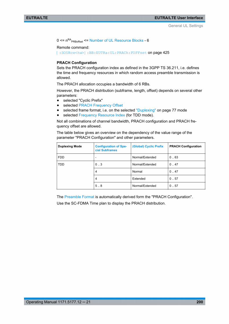
EUTRA/LTE User InterfaceEUTRA/LTE
200Operating Manual 1171.5177.12 ─ 21
0 <= nRAPRBoffset <= Number of UL Resource Blocks - 6
Remote command: [:SOURce<hw>]: BB:EUTRa:UL: PRACh:FOFFset on page 425
PRACH ConfigurationSets the PRACH configuration index as defined in the 3GPP TS 36.211, i.e. definesthe time and frequency resources in which random access preamble transmission isallowed.
The PRACH allocation occupies a bandwidth of 6 RBs.
However, the PRACH distribution (subframe, length, offset) depends on several otherparameters:● selected "Cyclic Prefix"● selected PRACH Frequency Offset● selected frame format, i.e. on the selected "Duplexing" on page 77 mode● selected Frequency Resource Index (for TDD mode).Not all combinations of channel bandwidth, PRACH configuration and PRACH fre-quency offset are allowed.
The table below gives an overview on the dependency of the value range of theparameter "PRACH Configuration" and other parameters.
Duplexing Mode Configuration of Spe-cial Subframes
(Global) Cyclic Prefix PRACH Configuration
FDD - Normal/Extended 0 .. 63
TDD 0 .. 3 Normal/Extended 0 .. 47
4 Normal 0 .. 47
4 Extended 0 .. 57
5 .. 8 Normal/Extended 0 .. 57
The Preamble Format is automatically derived form the "PRACH Configuration".
Use the SC-FDMA Time plan to display the PRACH distribution.
General UL Settings
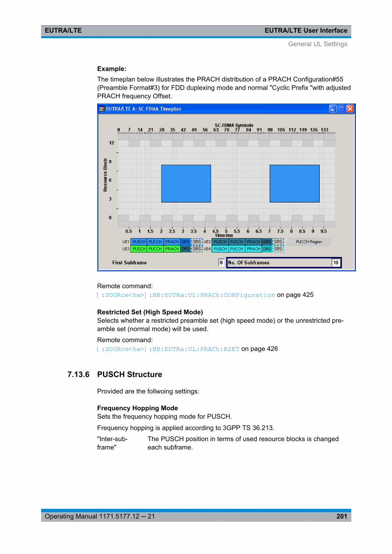
EUTRA/LTE User InterfaceEUTRA/LTE
201Operating Manual 1171.5177.12 ─ 21
Example: The timeplan below illustrates the PRACH distribution of a PRACH Configuration#55(Preamble Format#3) for FDD duplexing mode and normal "Cyclic Prefix "with adjustedPRACH frequency Offset.
Remote command: [:SOURce<hw>]: BB: EUTRa:UL: PRACh:CONFiguration on page 425
Restricted Set (High Speed Mode)Selects whether a restricted preamble set (high speed mode) or the unrestricted pre-amble set (normal mode) will be used.
Remote command: [: SOURce<hw>]: BB:EUTRa: UL:PRACh: RSET on page 426
7.13.6 PUSCH Structure
Provided are the follwoing settings:
Frequency Hopping ModeSets the frequency hopping mode for PUSCH.
Frequency hopping is applied according to 3GPP TS 36.213.
"Inter-sub-frame"
The PUSCH position in terms of used resource blocks is changedeach subframe.
General UL Settings
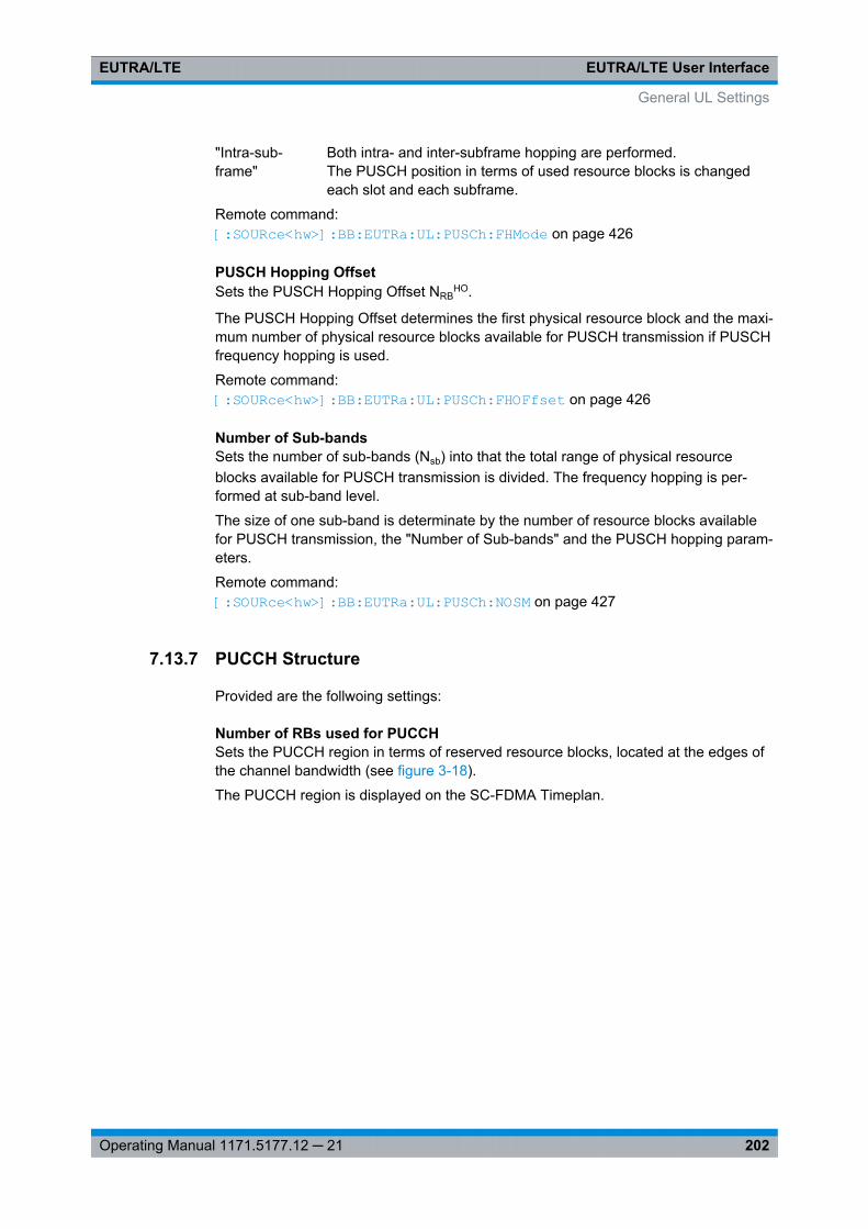
EUTRA/LTE User InterfaceEUTRA/LTE
202Operating Manual 1171.5177.12 ─ 21
"Intra-sub-frame"
Both intra- and inter-subframe hopping are performed.The PUSCH position in terms of used resource blocks is changedeach slot and each subframe.
Remote command: [:SOURce<hw>]: BB: EUTRa:UL: PUSCh:FHMode on page 426
PUSCH Hopping OffsetSets the PUSCH Hopping Offset NRB
HO.
The PUSCH Hopping Offset determines the first physical resource block and the maxi-mum number of physical resource blocks available for PUSCH transmission if PUSCHfrequency hopping is used.
Remote command: [:SOURce<hw>]: BB:EUTRa: UL:PUSCh: FHOFfset on page 426
Number of Sub-bandsSets the number of sub-bands (Nsb) into that the total range of physical resourceblocks available for PUSCH transmission is divided. The frequency hopping is per-formed at sub-band level.
The size of one sub-band is determinate by the number of resource blocks availablefor PUSCH transmission, the "Number of Sub-bands" and the PUSCH hopping param-eters.
Remote command: [: SOURce<hw>]: BB:EUTRa: UL:PUSCh:NOSM on page 427
7.13.7 PUCCH Structure
Provided are the follwoing settings:
Number of RBs used for PUCCHSets the PUCCH region in terms of reserved resource blocks, located at the edges ofthe channel bandwidth (see figure 3-18).
The PUCCH region is displayed on the SC-FDMA Timeplan.
General UL Settings
EUTRA/LTE User InterfaceEUTRA/LTE
203Operating Manual 1171.5177.12 ─ 21
Example: The figure below shows an example of a subframe with PUCCH region with threereserved resource blocks and PUCCH Format 2a.
Remote command: [:SOURce<hw>]: BB: EUTRa:UL: PUCCh:NORB on page 427
Delta ShiftSets the delta shift parameter, i.e. the cyclic shift difference between two adjacentPUCCH resource indices with the same orthogonal cover sequence (OC).
The delta shift determinates the number of available sequences in a resource blockthat can be used for PUCCH formats 1/1a/1b (see also chapter 3.2.3, "Uplink ControlInformation Transmission", on page 29).
Remote command: [:SOURce<hw>]: BB:EUTRa:UL: PUCCh:DESHift on page 427
N(1)_csSets the number of cyclic shifts used for PUCCH format 1/1a/1b in a resource blockused for a combination of the formats 1/1a/1b and 2/2a/2b.
Only one resource block per slot can support a combination of the PUCCH formats1/1a/1b and 2/2a/2b.
The number of cyclic shifts available for PUCCH format 2/2a/2b N(2)_cs in a block withcombination of PUCCH formats is calculated as follow:
N(2)_cs = 12 - N(1)_cs -2
Remote command: [: SOURce<hw>]: BB:EUTRa: UL:PUCCh: N1CS on page 428
N(2)_RBSets bandwidth in terms of resource blocks that are reserved for PUCCH formats2/2a/2b transmission in each subframe.
General UL Settings
EUTRA/LTE User InterfaceEUTRA/LTE
204Operating Manual 1171.5177.12 ─ 21
Since there can be only one resource block per slot that supports a combination of thePUCCH formats 1/1a/1b and 2/2a/2b, the number of resource block(s) per slot availa-ble for PUCCH format 1/1a/1b is determinate by "N(2)_RB".
Remote command: [:SOURce<hw>]: BB:EUTRa: UL:PUCCh: N2RB on page 428
Range n(1)_PUCCH (Normal CP)Displays the range of the possible PUCCH format 1/1a/1b transmissions from differentusers in one subframe and in case of normal CP.
Insufficient ranges are displayed as '-'.
This parameter determines the value range of index n_PUCCH for PUCCH format1/1a/1b in case of normal cyclic prefix.
Remote command: [:SOURce<hw>]: BB:EUTRa: UL:PUCCh: N1NMax on page 428
Range n(1)_PUCCH (Extended CP)Displays the range of the possible PUCCH format 1/1a/1b transmissions from differentusers in one subframe and in case of Extended CP.
Insufficient ranges are displayed as '-'.
Remote command: [:SOURce<hw>]: BB: EUTRa:UL: PUCCh:N1EMax on page 429
Range n(2)_PUCCHDisplays the range of possible number of PUCCH format 2/2a/2b transmissions fromdifferent users in one subframe.
Insufficient ranges are displayed as '-'.
Remote command: [:SOURce<hw>]: BB:EUTRa: UL: PUCCh:N2Max on page 429
Range n(3)_PUCCHDisplays the range of possible number of PUCCH format 3 transmissions from differentusers in one subframe.
Insufficient ranges are displayed as '-'.
Remote command: [: SOURce<hw>]: BB:EUTRa: UL:PUCCh:N3Max on page 430
7.13.8 SRS Structure
The cell specific parameters in this section determine the structure of the sounding ref-erence signal (SRS) according to the 3GPP TS 36.211.
The UE-specific parameters, necessary for the complete definition of the SRS structureand SRS mapping, are configurable in the User Equipment Configuration dialog of thecorresponding UE.
To enable an aperiodic SRS transmission, use the parameter Aperiodic SRS.
General UL Settings
EUTRA/LTE User InterfaceEUTRA/LTE
205Operating Manual 1171.5177.12 ─ 21
SRS Subframe ConfigurationSets the cell specific parameter SRS subframe configuration.
This parameter can also influence the shortening of PUCCH/PUSCH transmissions,regardless whether the UEs are configured to send a SRS in the according subframeor not.
Remote command: [:SOURce<hw>]: BB:EUTRa:UL: REFSig:SRS: SUConfiguration on page 424
Configuration Period T_SFCDisplays the value for the cell specific parameter configuration period TSFC in sub-frames, depending on the selected "SRS Subframe Configuration" and the "Duplexing"mode.
Remote command: [:SOURce<hw>]: BB: EUTRa:UL:REFSig: SRS:TSFC? on page 425
Transmission Offset Delta_SFCDisplays the value for the cell specific parameter transmission offset DeltaSFC in sub-frames, depending on the selected "SRS Subframe Configuration" and the "Duplexing"mode.
Remote command: [:SOURce<hw>]: BB:EUTRa: UL:REFSig: SRS:DSFC? on page 424
SRS Bandwidth Configuration C_SRSSets the cell specific parameter SRS Bandwidth Configuration (CSRS).
The SRS Bandwidth Configuration CSRS, theSRS Bandwidth B_SRS and the ChannelBandwidth (UL) determine the length of the sounding reference signal sequence, cal-culated according to 3GPP TS 36.211.
Remote command: [:SOURce<hw>]: BB:EUTRa:UL: REFSig:SRS: CSRS on page 424
A/N + SRS simultaneous TxEnables/disables simultaneous transmission of SRS (sounding reference signal) andACK/NACK messages, i.e. transmission of SRS and PUCCH in the same subframe.
Simultaneous transmission of SRS and PUCCH is allowed only for PUCCH formats 11,1a, 1b and 3, since CQI reports are never simultaneously transmitted with SRS.
If this parameter is disabled, the SRS is not transmitted in the corresponding subframe.
Remote command: [:SOURce<hw>]: BB:EUTRa: UL:REFSig: SRS:ANSTx on page 423
SRS MaxUpPTSEnables/disables the cell specific parameter srsMaxUpPts.
If enabled, a SRS transmission in the UpPTS field (TDD) is made only in the frequencyarea that does not overlap with the frequency resources reserved for a possiblePRACH preamble format 4 transmission.
General UL Settings
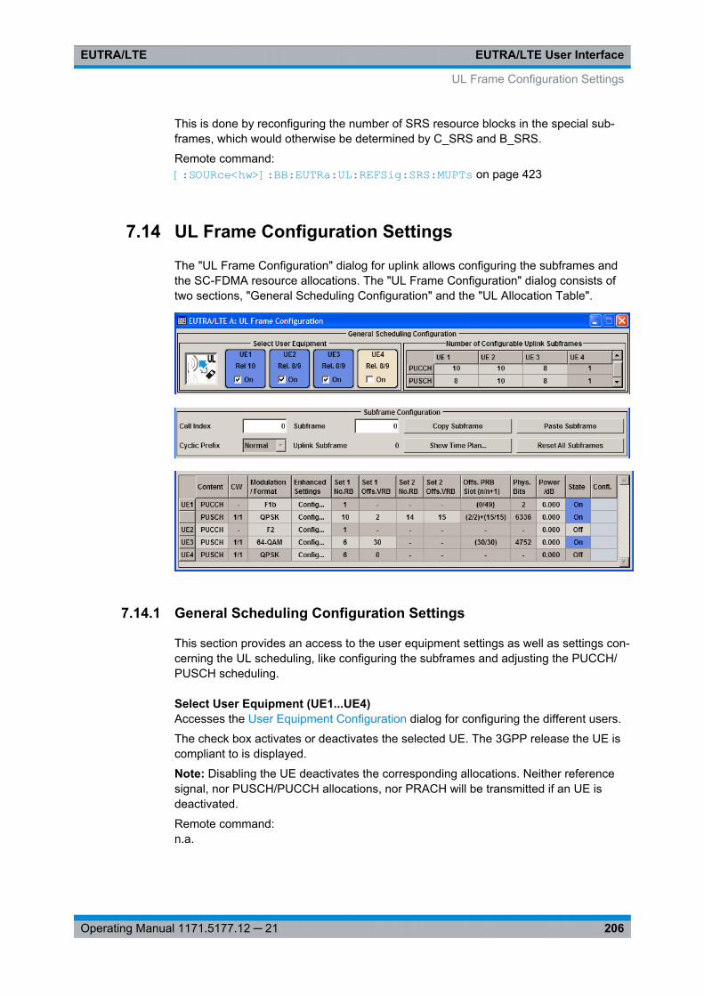
EUTRA/LTE User InterfaceEUTRA/LTE
206Operating Manual 1171.5177.12 ─ 21
This is done by reconfiguring the number of SRS resource blocks in the special sub-frames, which would otherwise be determined by C_SRS and B_SRS.
Remote command: [:SOURce<hw>]: BB:EUTRa: UL:REFSig: SRS:MUPTs on page 423
7.14 UL Frame Configuration Settings
The "UL Frame Configuration" dialog for uplink allows configuring the subframes andthe SC-FDMA resource allocations. The "UL Frame Configuration" dialog consists oftwo sections, "General Scheduling Configuration" and the "UL Allocation Table".
7.14.1 General Scheduling Configuration Settings
This section provides an access to the user equipment settings as well as settings con-cerning the UL scheduling, like configuring the subframes and adjusting the PUCCH/PUSCH scheduling.
Select User Equipment (UE1...UE4)Accesses the User Equipment Configuration dialog for configuring the different users.
The check box activates or deactivates the selected UE. The 3GPP release the UE iscompliant to is displayed.
Note: Disabling the UE deactivates the corresponding allocations. Neither referencesignal, nor PUSCH/PUCCH allocations, nor PRACH will be transmitted if an UE isdeactivated.
Remote command: n.a.
UL Frame Configuration Settings
EUTRA/LTE User InterfaceEUTRA/LTE
207Operating Manual 1171.5177.12 ─ 21
Number Of PUCCH/PUSCH Configations/Number Of Configurable SubframesSets the number of configurable subframes in the up to four configurable frames, i.edetermines the scheduling cycle per UE.
All uplink subframes are filled periodically with the configured subframes with theexception of the Sounding Reference Signal. SRS is set individually for each UE in theUser Equipment Configuration dialog.
The maximum number of configurable subframes depends on the selected Duplexingmode (TDD or FDD), TDD Frame Structure Settings and whether a realtime feedbackis enabled or not.
For more detailed information about the maximum number of configurable subframesand for description of the dependencies between the parameters, see chapter 5.2.3,"Four Configurable Frames in Uplink and Downlink Direction", on page 54.
For "Rel 8/9" UEs, the "No Of Configurable Uplink Subframes" is the same for PUCCHand PUSCH.
In instruments equipped with R&S SMx/AMU-K85, for the LTE Rel 10 UEs, the sched-uling cycles are additionally independent per PUSCH and PUCCH, i.e. the number ofconfigurable subframes can be defined individually per PUCCH and per PUSCH. Thisenables the configuration of PUCCH and PUSCH with different repetition patterns.
Example: Independent cycles for PUSCH and PUCCH of the same LTE Rel. 10 UEAs described in the test case 8.2.4, TS 36.141 [6], the PUCCH of the UE has to betransmitted once a frame and the PUSCH - once each eight subframes.● Set "UE1 > User Equipment Configuration > 3GPP Release" = Release 10.● In the "UL Frame Configuration > Number of Configurable Uplink Subframes" dia-
log, set "UE1 > PUCCH" = 10● In the "UL Frame Configuration > Number of Configurable Uplink Subframes" dia-
log, set "UE1 > PUSCH" = 8● Configure the PUCCH and PUSCH allocations of UE1 as required.
UL Frame Configuration Settings
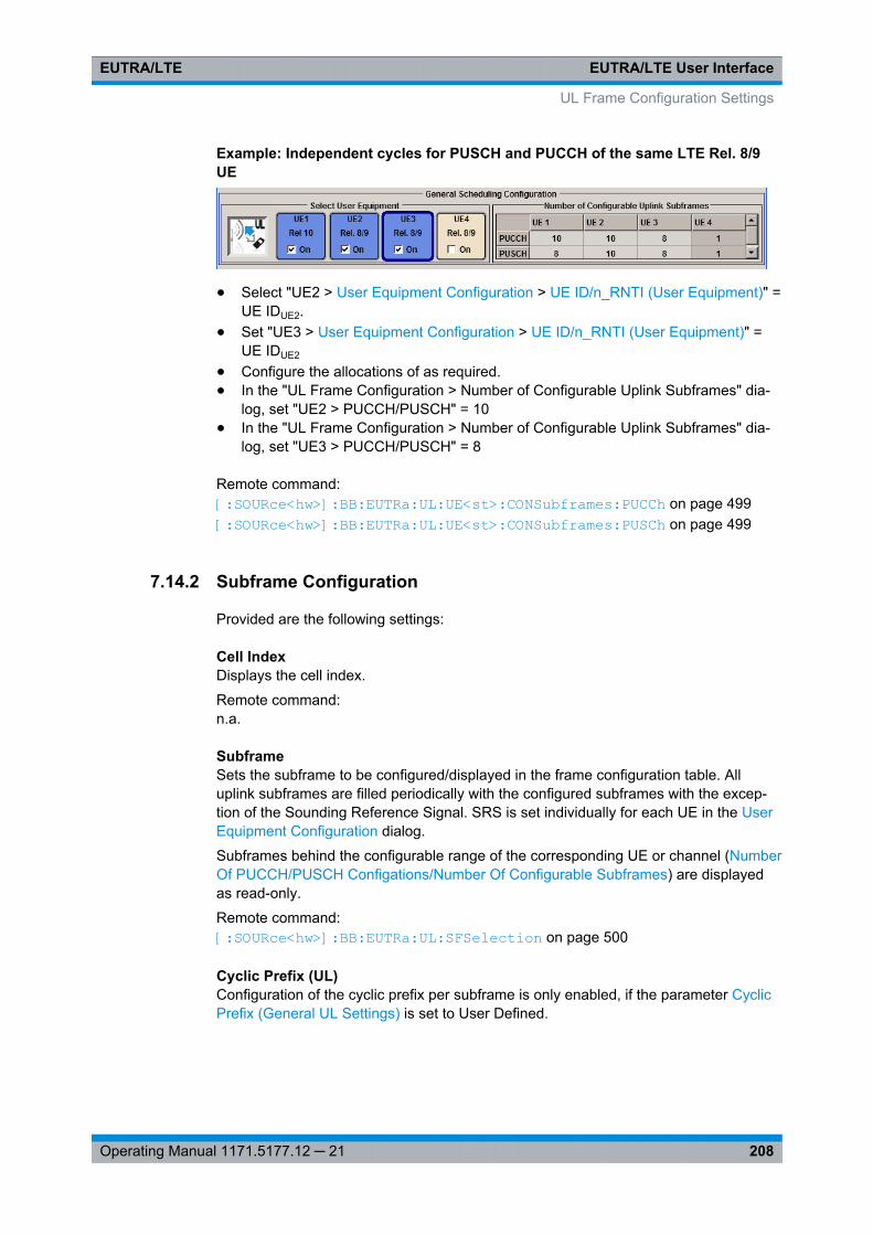
EUTRA/LTE User InterfaceEUTRA/LTE
208Operating Manual 1171.5177.12 ─ 21
Example: Independent cycles for PUSCH and PUCCH of the same LTE Rel. 8/9UE
● Select "UE2 > User Equipment Configuration > UE ID/n_RNTI (User Equipment)" =UE IDUE2.
● Set "UE3 > User Equipment Configuration > UE ID/n_RNTI (User Equipment)" =UE IDUE2
● Configure the allocations of as required.● In the "UL Frame Configuration > Number of Configurable Uplink Subframes" dia-
log, set "UE2 > PUCCH/PUSCH" = 10● In the "UL Frame Configuration > Number of Configurable Uplink Subframes" dia-
log, set "UE3 > PUCCH/PUSCH" = 8
Remote command: [: SOURce<hw>]: BB:EUTRa: UL:UE<st>: CONSubframes: PUCCh on page 499[: SOURce<hw>]: BB:EUTRa: UL:UE<st>: CONSubframes: PUSCh on page 499
7.14.2 Subframe Configuration
Provided are the following settings:
Cell IndexDisplays the cell index.
Remote command: n.a.
SubframeSets the subframe to be configured/displayed in the frame configuration table. Alluplink subframes are filled periodically with the configured subframes with the excep-tion of the Sounding Reference Signal. SRS is set individually for each UE in the UserEquipment Configuration dialog.
Subframes behind the configurable range of the corresponding UE or channel (NumberOf PUCCH/PUSCH Configations/Number Of Configurable Subframes) are displayedas read-only.
Remote command: [: SOURce<hw>]: BB:EUTRa: UL:SFSelection on page 500
Cyclic Prefix (UL)Configuration of the cyclic prefix per subframe is only enabled, if the parameter CyclicPrefix (General UL Settings) is set to User Defined.
UL Frame Configuration Settings
EUTRA/LTE User InterfaceEUTRA/LTE
209Operating Manual 1171.5177.12 ─ 21
The number of the SC-FDMA symbols per subframe is set automatically
Remote command: [:SOURce<hw>]: BB:EUTRa: UL[:SUBF<st0>]: CYCPrefix on page 500
Subframe InformationDisplays the kind of the selected subframe, i.e. "Special Subframe", "Uplink Subframe","Downlink Subframe".
For "Uplink Subframe", it is also shown the uplink subframe number, which is espe-cially useful for TDD duplexing mode.
Remote command: n.a.
Copy/Paste Subframe SettingsCopies/pastes the settings of the selected subframe. Sounding Reference Signals arenot considered.
For more detailed information, see chapter 5.2.1, "Copy/Paste Subframe", on page 53.
Remote command: n.a.
Show Time PlanCalls the time plan for the SC-FDMA resource allocation.
The dialog is described in detail in section chapter 7.18, "SC-FDMA Timeplan",on page 248.
Remote command: n.a.
Reset All SubframesResets settings of all subframes including cyclic prefix to the default values.
Remote command: [:SOURce<hw>]: BB:EUTRa:UL: RSTFrame on page 500
7.14.3 UL Allocation Table
The resource allocation table is located in the lower part of the "UL Frame Configura-tion" dialog. The resource allocation table is where the individual allocation parametersfor a subframe are set.
Content (UL)Selects the content type of the selected allocation.
Data source settings for PUSCH is configurable in dialog chapter 7.15, "User Equip-ment Configuration", on page 213.
Remote command: [:SOURce<hw>]: BB:EUTRa: UL[:SUBF<st0>]: ALLoc<ch0>: CONType on page 500
UL Frame Configuration Settings
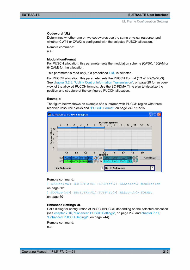
EUTRA/LTE User InterfaceEUTRA/LTE
210Operating Manual 1171.5177.12 ─ 21
Codeword (UL)Determines whether one or two codewords use the same physical resource, andwhether CW#1 or CW#2 is configured with the selected PUSCH allocation.
Remote command: n.a.
Modulation/FormatFor PUSCH allocation, this parameter sets the modulation scheme (QPSK, 16QAM or64QAM) for the allocation.
This parameter is read-only, if a predefined FRC is selected.
For PUCCH allocation, this parameter sets the PUCCH Format (1/1a/1b/2/2a/2b/3).See chapter 3.2.3, "Uplink Control Information Transmission", on page 29 for an over-view of the allowed PUCCH formats. Use the SC-FDMA Time plan to visualize theposition and structure of the configured PUCCH allocation.
Example: The figure below shows an example of a subframe with PUCCH region with threereserved resource blocks and "PUCCH Format" on page 245 1/1a/1b.
Remote command: [:SOURce<hw>]: BB: EUTRa:UL[: SUBF<st0>]: ALLoc<ch0>: MODulation on page 501[:SOURce<hw>]: BB: EUTRa:UL[: SUBF<st0>]: ALLoc<ch0>: FORMaton page 501
Enhanced Settings ULCalls dialog for configuration of PUSCH/PUCCH depending on the selected allocation(see chapter 7.16, "Enhanced PUSCH Settings", on page 239 and chapter 7.17,"Enhanced PUCCH Settings", on page 244).
Remote command: n.a.
UL Frame Configuration Settings

EUTRA/LTE User InterfaceEUTRA/LTE
211Operating Manual 1171.5177.12 ─ 21
Set 1/Set 2 No. RBRequires option R&S SMx/AMU-K85 LTE-A (Rel. 10)
The LTE Rel. 10 specification defines PUSCH transmission not only in a continuousfrequency region but also in two "sets" or "clusters" of resource blocks (see fig-ure 3-27).
This parameters defines the size of the selected allocation in resource blocks of thecorresponding set.
This parameter is read-only, if a predefined FRC is selected.
Example: Clustered PUSCH Tranmission● Select "User Equipment Configuration (UE1) > 3GPP Release > Rel.10".● In the "UL Frame Configuration > Allocation Table", configure the PUSCH alloca-
tion of UE1 as follow:– "Set 1 No. RB" = 10, "Set 1 Offs. VRB" = 2– "Set 2 No. RB" = 5, "Set 2 Offs. VRB" = 25– "State" = ON
● Select "Show Time Plan" to visualize the configured allocations
Remote command: [:SOURce<hw>]: BB: EUTRa:UL[: SUBF<st0>]: ALLoc<ch0>: RBCounton page 501[:SOURce<hw>]: BB: EUTRa:UL[: SUBF<st0>]: ALLoc<ch0>: PUCCh:RBCount? on page 501[:SOURce<hw>]: BB: EUTRa:UL[: SUBF<st0>]: ALLoc<ch0>: PUSCh:SET<user>: RBCount on page 501
Set 1/Set 2 Offset VRBRequires optionR&S SMx/AMU-K85 LTE-A (Rel. 10)
UL Frame Configuration Settings
EUTRA/LTE User InterfaceEUTRA/LTE
212Operating Manual 1171.5177.12 ─ 21
For the corresponding set, sets the virtual resource block offset of the selected sub-frame (see also example "Clustered PUSCH Tranmission" on page 211).
This parameter is read-only, if a predefined FRC is selected.
Remote command: [:SOURce<hw>]: BB:EUTRa: UL[:SUBF<st0>]: ALLoc<ch0>: VRBoffset on page 502[:SOURce<hw>]: BB:EUTRa: UL[:SUBF<st0>]: ALLoc<ch0>: PUSCh: SET<user>: VRBoffset on page 502
Offs PRB Slot (n/n+1)Displays the start resource block of the selected allocation in the first and the secondslot of the subframe.
The start physical resource block in slot n and slot n+1 are set automatically and candeviate from the Set 1/Set 2 Offset VRB if frequency hopping is used.
In case an intra-subframe hopping for hopping type 2 is applied, the start resourceblock in slot 1 is determinate by the selected Number of Sub-bands.
Remote command: [: SOURce<hw>]: BB:EUTRa: UL[:SUBF<st0>]: SLOT<user0>: ALLoc<ch0>: RBOFfset? on page 502[: SOURce<hw>]: BB:EUTRa: UL[:SUBF<st0>]: SLOT<user0>: ALLoc<ch0>: PUCCh: RBOFfset? on page 502[: SOURce<hw>]: BB:EUTRa: UL[:SUBF<st0>]: SLOT<user0>: ALLoc<ch0>: PUSCh: SET<gr>: RBOFfset? on page 502
Phys. Bits / Total Number of Physical BitsDisplays the size of the selected allocation in bits. The value is set automaticallyaccording to the current allocation's settings.
Remote command: [: SOURce<hw>]: BB:EUTRa: UL[:SUBF<st0>]: ALLoc<ch0>: PHYSbits? on page 503[: SOURce<hw>]: BB:EUTRa: UL[:SUBF<st0>]: ALLoc<ch0>: PUCCh: PHYSbits? on page 503[: SOURce<hw>]: BB:EUTRa: UL[:SUBF<st0>]: ALLoc<ch0>: PUSCh: PHYSbits? on page 503
Power (UL)Sets the power for the selected allocation, i.e. PUSCH or PUCCH power level.
The PUSCH power level (PPUSCH) and the PUCCH power level (PPUCCH) can vary persubframe.
For global adjustment of the transmit power of the corresponding UE, use the parame-ter UE Power (PUE).
UL Frame Configuration Settings
EUTRA/LTE User InterfaceEUTRA/LTE
213Operating Manual 1171.5177.12 ─ 21
An additional boost of the reference signals DRS and SRS per UE can be applied withthe parameters DRS Power Offset (PDRS_offset) and SRS Power Offset (PSRS_offset)respectively.
Remote command: [:SOURce<hw>]: BB:EUTRa: UL[:SUBF<st0>]: ALLoc<ch0>: POWer on page 503[:SOURce<hw>]: BB:EUTRa: UL[:SUBF<st0>]: ALLoc<ch0>: PUCCh: POWer on page 503[:SOURce<hw>]: BB:EUTRa: UL[:SUBF<st0>]: ALLoc<ch0>: PUSCh: POWer on page 503
State (UL)Sets the allocation to active or inactive state.
Note: Disabling an allocation deactivate the PUSCH/PUCCH and the correspondingdemodulation reference signal, but does not affect other allocations of the UE or thesounding reference signal.
Remote command: [: SOURce<hw>]: BB:EUTRa: UL[:SUBF<st0>]: ALLoc<ch0>: STATe on page 503[: SOURce<hw>]: BB:EUTRa: UL[:SUBF<st0>]: ALLoc<ch0>: PUCCh: STATeon page 503[: SOURce<hw>]: BB:EUTRa: UL[:SUBF<st0>]: ALLoc<ch0>: PUSCh: STATeon page 503
Conflict (UL)Indicates a conflict between UEs and in case an allocation exceeds the available num-ber of resource blocks.
For more information, see chapter 5.1, "Conflict Handling", on page 49.
Remote command: [:SOURce<hw>]: BB: EUTRa:UL[: SUBF<st0>]: ALLoc<ch0>: CONFlict? on page 504[:SOURce<hw>]: BB: EUTRa:UL[: SUBF<st0>]: ALLoc<ch0>: PUCCh:CONFlict? on page 504[:SOURce<hw>]: BB: EUTRa:UL[: SUBF<st0>]: ALLoc<ch0>: PUSCh:CONFlict? on page 504
7.15 User Equipment Configuration
The "User Equipment 1 - 4" dialogs for users 1 to 4 allows to define and configure upto four scheduled user equipments that can be freely distributed over the time. Foreach user equipment, the structure of the demodulation reference signal and thesounding reference signal can be configured individually.
The "User Equipment 1 – 4" dialog consists of four to five main sections "Common Set-tings", "FRC Configuration", "Physical Uplink Shared Channel (PUSCH)" and "Refer-ence Signal Structure". Section "Realtime Feedback Configuration" is enabled only forinstrument equipped with the option R&S SMx/AMU-K69.
User Equipment Configuration
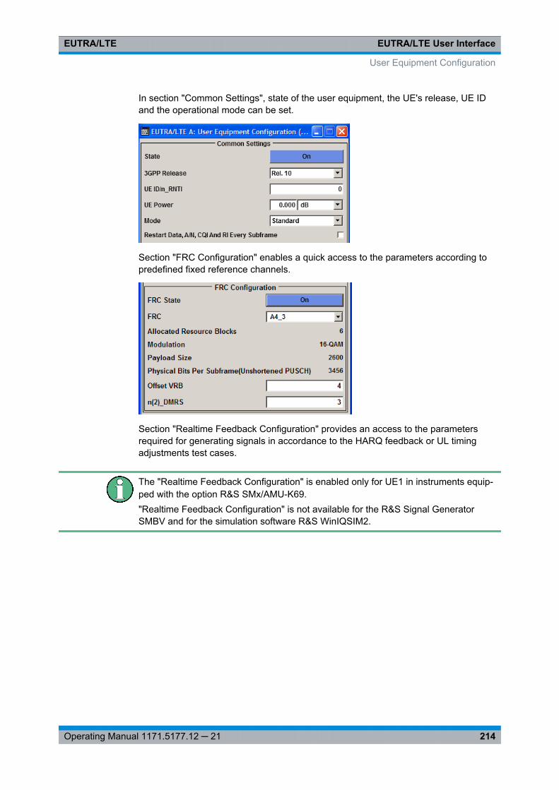
EUTRA/LTE User InterfaceEUTRA/LTE
214Operating Manual 1171.5177.12 ─ 21
In section "Common Settings", state of the user equipment, the UE's release, UE IDand the operational mode can be set.
Section "FRC Configuration" enables a quick access to the parameters according topredefined fixed reference channels.
Section "Realtime Feedback Configuration" provides an access to the parametersrequired for generating signals in accordance to the HARQ feedback or UL timingadjustments test cases.
The "Realtime Feedback Configuration" is enabled only for UE1 in instruments equip-ped with the option R&S SMx/AMU-K69."Realtime Feedback Configuration" is not available for the R&S Signal GeneratorSMBV and for the simulation software R&S WinIQSIM2.
User Equipment Configuration

EUTRA/LTE User InterfaceEUTRA/LTE
215Operating Manual 1171.5177.12 ─ 21
In section "Physical Uplink Shared Channel (PUSCH)", the data source for the PUSCHcan be selected and channel coding can be configured. Use the Enhanced PUSCHSettings dialog to adjust the additional settings for channel coding of the control infor-mation and the multiplexing of the data and control information.
Section "Reference Signal Structure" is where reference signal structure can be config-ured individually for demodulation and sounding purposes.
User Equipment Configuration

EUTRA/LTE User InterfaceEUTRA/LTE
216Operating Manual 1171.5177.12 ─ 21
The "PRACH Power Ramping" and "PRACH Configuration" settings are availablewhen the user equipment "Mode" is set to PRACH.
7.15.1 Common Settings
In section "Common Settings", the state of the user equipment, the UE's release, UEID and the operational mode can be set.
State (User Equipment)Activates or deactivates the user equipment.
User Equipment Configuration
EUTRA/LTE User InterfaceEUTRA/LTE
217Operating Manual 1171.5177.12 ─ 21
Note: Disabling the UE deactivates the corresponding allocations. Neither referencesignal, nor PUSCH/PUCCH allocations, nor PRACH will be transmitted if an UE isdeactivated.
Remote command: [:SOURce<hw>]: BB:EUTRa: UL:UE<st>: STATe on page 524
3GPP Releaserequires option R&S SMx/AMU-K85 (LTE-A Rel. 10)
Determines whether the selected UE is a LTE Release 8/9 or LTE Release 10 UE.Several further settings are enabled only for Rel. 10 UEs (e.g. see chapter 7.14, "ULFrame Configuration Settings", on page 206).
Remote command: [:SOURce<hw>]: BB: EUTRa:UL: UE<st>:RELease on page 523
UE ID/n_RNTI (User Equipment)Sets the radio network temporary identifier (RNTI) of the UE.
Remote command: [: SOURce<hw>]: BB:EUTRa: UL:UE<st>: ID on page 524
UE PowerSets the power level of the selected UE (PUE).
The UE power level determines the power levels of the reference signals (DRS andSRS) and the power level of the allocations (PUSCH (PPUSCH) and PUCCH (PPUCCH)).
The UE power level can be used for global adjustment of the transmit power of the cor-responding UE.
The PUSCH and PUCCH Power level can vary per subframe.
An additional boost of the reference signals DRS and SRS per UE can be applied withthe parameters DRS Power Offset (PDSR_offset) and SRS Power Offset (PSRS_offset)respectively.
Remote command: [:SOURce<hw>]: BB:EUTRa: UL:UE<st>: POWer on page 525
ModeSelects whether the user equipment is in standard or in PRACH mode.
"Standard" Sets the operational mode of the user equipment to standard.
"PRACH" Sets the operational mode of the user equipment to PRACH (seechapter 7.15.9, "PRACH Configuration", on page 237).
Remote command: [:SOURce<hw>]: BB: EUTRa:UL: UE<st>:MODE on page 524
Restart Data, A/N, CQI and RI every subframeIf activated, the data source, the ACK/NACK pattern, the CQI pattern and RI are restar-ted every subframe.
User Equipment Configuration
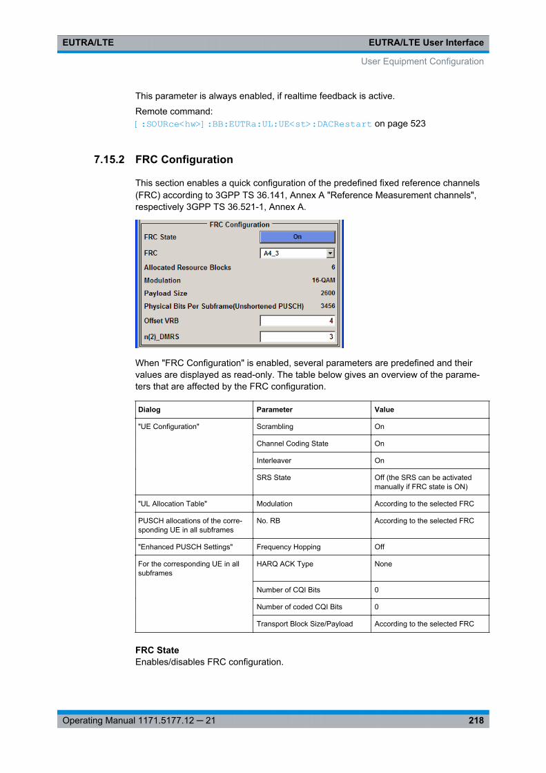
EUTRA/LTE User InterfaceEUTRA/LTE
218Operating Manual 1171.5177.12 ─ 21
This parameter is always enabled, if realtime feedback is active.
Remote command: [:SOURce<hw>]: BB:EUTRa: UL:UE<st>: DACRestart on page 523
7.15.2 FRC Configuration
This section enables a quick configuration of the predefined fixed reference channels(FRC) according to 3GPP TS 36.141, Annex A "Reference Measurement channels",respectively 3GPP TS 36.521-1, Annex A.
When "FRC Configuration" is enabled, several parameters are predefined and theirvalues are displayed as read-only. The table below gives an overview of the parame-ters that are affected by the FRC configuration.
Dialog Parameter Value
"UE Configuration" Scrambling On
Channel Coding State On
Interleaver On
SRS State Off (the SRS can be activatedmanually if FRC state is ON)
"UL Allocation Table" Modulation According to the selected FRC
PUSCH allocations of the corre-sponding UE in all subframes
No. RB According to the selected FRC
"Enhanced PUSCH Settings" Frequency Hopping Off
For the corresponding UE in allsubframes
HARQ ACK Type None
Number of CQI Bits 0
Number of coded CQI Bits 0
Transport Block Size/Payload According to the selected FRC
FRC StateEnables/disables FRC configuration.
User Equipment Configuration
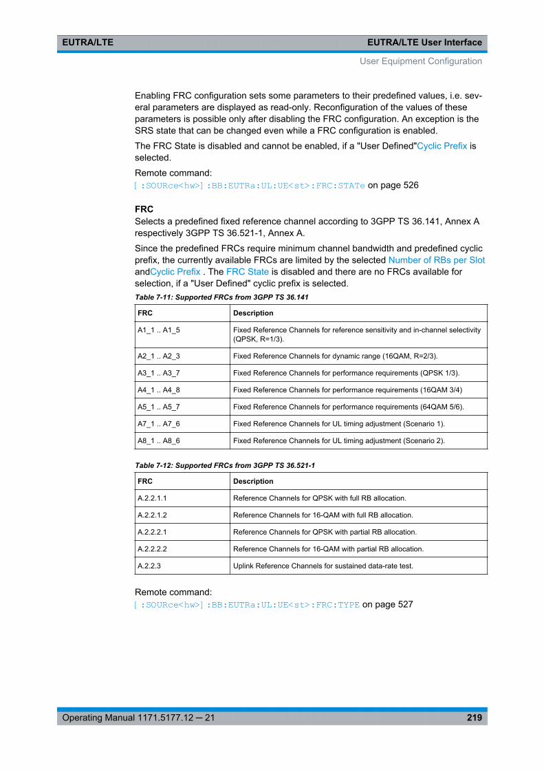
EUTRA/LTE User InterfaceEUTRA/LTE
219Operating Manual 1171.5177.12 ─ 21
Enabling FRC configuration sets some parameters to their predefined values, i.e. sev-eral parameters are displayed as read-only. Reconfiguration of the values of theseparameters is possible only after disabling the FRC configuration. An exception is theSRS state that can be changed even while a FRC configuration is enabled.
The FRC State is disabled and cannot be enabled, if a "User Defined"Cyclic Prefix isselected.
Remote command: [:SOURce<hw>]: BB:EUTRa: UL:UE<st>: FRC:STATe on page 526
FRCSelects a predefined fixed reference channel according to 3GPP TS 36.141, Annex Arespectively 3GPP TS 36.521-1, Annex A.
Since the predefined FRCs require minimum channel bandwidth and predefined cyclicprefix, the currently available FRCs are limited by the selected Number of RBs per SlotandCyclic Prefix . The FRC State is disabled and there are no FRCs available forselection, if a "User Defined" cyclic prefix is selected.Table 7-11: Supported FRCs from 3GPP TS 36.141
FRC Description
A1_1 .. A1_5 Fixed Reference Channels for reference sensitivity and in-channel selectivity(QPSK, R=1/3).
A2_1 .. A2_3 Fixed Reference Channels for dynamic range (16QAM, R=2/3).
A3_1 .. A3_7 Fixed Reference Channels for performance requirements (QPSK 1/3).
A4_1 .. A4_8 Fixed Reference Channels for performance requirements (16QAM 3/4)
A5_1 .. A5_7 Fixed Reference Channels for performance requirements (64QAM 5/6).
A7_1 .. A7_6 Fixed Reference Channels for UL timing adjustment (Scenario 1).
A8_1 .. A8_6 Fixed Reference Channels for UL timing adjustment (Scenario 2).
Table 7-12: Supported FRCs from 3GPP TS 36.521-1
FRC Description
A.2.2.1.1 Reference Channels for QPSK with full RB allocation.
A.2.2.1.2 Reference Channels for 16-QAM with full RB allocation.
A.2.2.2.1 Reference Channels for QPSK with partial RB allocation.
A.2.2.2.2 Reference Channels for 16-QAM with partial RB allocation.
A.2.2.3 Uplink Reference Channels for sustained data-rate test.
Remote command: [:SOURce<hw>]: BB: EUTRa:UL: UE<st>:FRC: TYPE on page 527
User Equipment Configuration
EUTRA/LTE User InterfaceEUTRA/LTE
220Operating Manual 1171.5177.12 ─ 21
Allocated Resource BlocksDisplays the number of the allocated resource blocks for the selected FRC. For FRCs"A.2.2.2.1" and "A.2.2.2.2" this parameter can also be set to different values accordingto 3GPP TS 36.521-1.
Remote command: [:SOURce<hw>]: BB: EUTRa:UL: UE<st>:FRC: ALRB on page 525
Modulation (FRC)Displays the modulation for the selected FRC.
Remote command: [:SOURce<hw>]: BB: EUTRa:UL:UE<st>: FRC: ALRB on page 525
Payload Size (FRC)Displays the payload size for the selected FRC.
Remote command: [:SOURce<hw>]: BB:EUTRa:UL: UE<st>:FRC: PASize? on page 526
Physical Bits Per Subframe (Unshortened PUSCH)Displays the total number of physical bits available for the PUSCH allocation per sub-frame, in that unshortened PUSCH is transmitted. Shortened PUSCH transmissionsoccurs in a cell specific SRS subframe or in subframes where SRS is transmitted.
Remote command: [:SOURce<hw>]: BB:EUTRa: UL:UE<st>: FRC:TNOBits? on page 527
Offset VRB (FRC)Sets the virtual resource block (VRB) offset for all PUSCH allocation of the selectedUE in all subframes.
The VRB Offset set for the individual subframes in the "UL Allocation Table" are over-written.
Remote command: [:SOURce<hw>]: BB:EUTRa: UL:UE<st>:FRC: VRBoffset on page 528
n(2)_DMRS (FRC)Sets the UE specific part of the demodulation reference signal (DMRS) index for allPUSCH allocation of the selected UE in all subframes.
The n(2)_DMRS set for the individual subframes in the "Enhanced PUSCH Settings"dialog for the corresponding UE is overwritten.
Remote command: [:SOURce<hw>]: BB:EUTRa: UL:UE<st>: FRC:N2DMrs on page 526
7.15.3 Realtime Feedback Configuration Settings
The EUTRA/LTE uplink realtime feedback functionality requires the additional optionR&S SMx/AMU-K69 Closed Loop BS Tests. This option extends the EUTRA/LTEoption R&S SMx/AMU-K55 with the possibility to perform closed loop performancetests with feedback as defined in 3GPP TS 36.141, chapter 8.
User Equipment Configuration
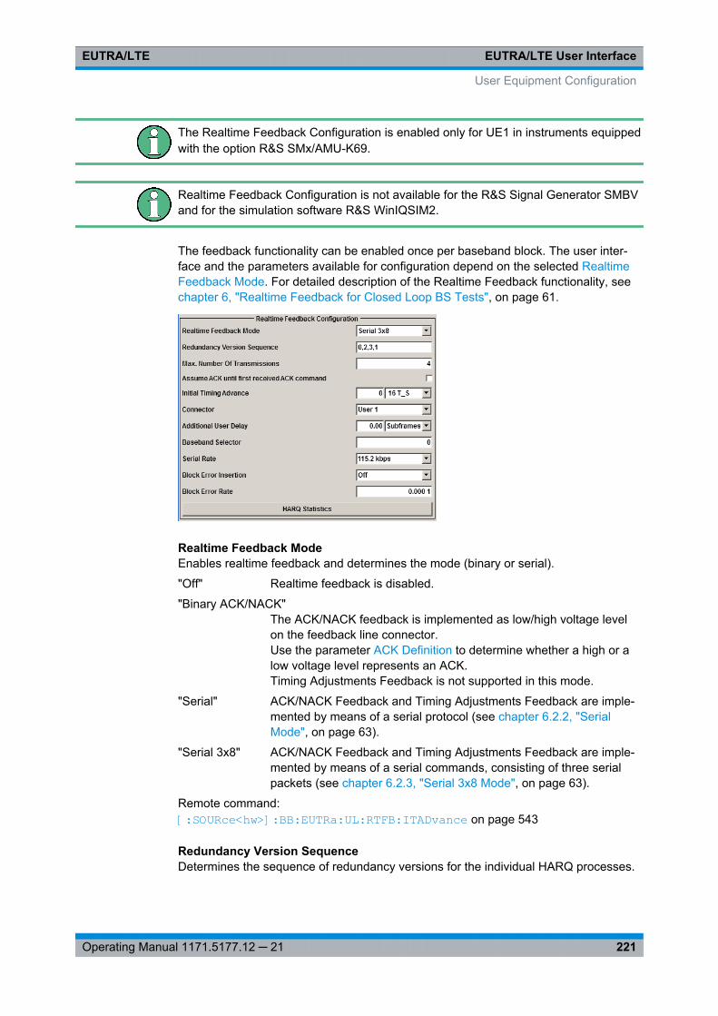
EUTRA/LTE User InterfaceEUTRA/LTE
221Operating Manual 1171.5177.12 ─ 21
The Realtime Feedback Configuration is enabled only for UE1 in instruments equippedwith the option R&S SMx/AMU-K69.
Realtime Feedback Configuration is not available for the R&S Signal Generator SMBVand for the simulation software R&S WinIQSIM2.
The feedback functionality can be enabled once per baseband block. The user inter-face and the parameters available for configuration depend on the selected RealtimeFeedback Mode. For detailed description of the Realtime Feedback functionality, seechapter 6, "Realtime Feedback for Closed Loop BS Tests", on page 61.
Realtime Feedback ModeEnables realtime feedback and determines the mode (binary or serial).
"Off" Realtime feedback is disabled.
"Binary ACK/NACK"The ACK/NACK feedback is implemented as low/high voltage levelon the feedback line connector.Use the parameter ACK Definition to determine whether a high or alow voltage level represents an ACK.Timing Adjustments Feedback is not supported in this mode.
"Serial" ACK/NACK Feedback and Timing Adjustments Feedback are imple-mented by means of a serial protocol (see chapter 6.2.2, "SerialMode", on page 63).
"Serial 3x8" ACK/NACK Feedback and Timing Adjustments Feedback are imple-mented by means of a serial commands, consisting of three serialpackets (see chapter 6.2.3, "Serial 3x8 Mode", on page 63).
Remote command: [:SOURce<hw>]: BB: EUTRa:UL: RTFB:ITADvance on page 543
Redundancy Version SequenceDetermines the sequence of redundancy versions for the individual HARQ processes.
User Equipment Configuration
EUTRA/LTE User InterfaceEUTRA/LTE
222Operating Manual 1171.5177.12 ─ 21
Unless otherwise requested by serial feedback commands, the first value in thesequence of redundancy versions is used each time an ACK is received or for the veryfirst transmission of a process.
The sequence of redundancy versions is read out cyclically, i.e. whenever a NACK isreceived and a retransmission is requested, the next redundancy version in thesequence is used.
The first value in the sequence is used again even in case a NACK is received, if theMax. Number of Transmissions in a process was reached.
Remote command: [:SOURce<hw>]: BB:EUTRa: UL:RTFB: RVSequence on page 544
Max. Number of TransmissionsAfter this maximum number of transmissions (incl. first transmission), the first redun-dancy version of the redundancy version sequence is used even in case of NACK.
Remote command: [:SOURce<hw>]: BB:EUTRa: UL:RTFB: MAXTrans on page 543
Assume ACK until first received ACK command("Serial/Serial 3x8" mode only)
If this parameter is enabled, the signal generator will not use any external HARQ feed-back from the device under test for its HARQ processes until an ACK command isreceived the first time. Until that, the generator will behave as if ACK was received forall transmissions - no matter if actually a NACK was received or if no HARQ feedbackwas received at all. It therefore will not schedule any retransmissions until ACK isreceived the first time.
This function can be useful for synchronization purposes, see chapter 6.4, "AvoidingSynchronization Problems", on page 70.
Note: This function applies independently for every HARQ process, i.e. if this parame-ter is enabled, an ACK has to be received in every HARQ process first, before the gen-erator stops ignoring any NACKs.
Remote command: [:SOURce<hw>]: BB:EUTRa: UL:RTFB: AACK on page 540
Initial Timing AdvanceThe initial timing advance of the uplink signal (at the output of the instrument's base-band unit) in units of 16 TS.
An initial timing advance greater than zero means that the beginning of the very firstsubframe of the uplink signal is omitted.
For binary feedback, the timing advance of the uplink signal stays constant (and equalto the initial timing advance) throughout the whole signal output.
The additional timing offset NTA offset for TDD, as defined in TS 36.211, is set by theparameter Signal Advance N_TA_offset.
Remote command: [:SOURce<hw>]: BB:EUTRa: UL:RTFB:ITADvance on page 543
User Equipment Configuration
EUTRA/LTE User InterfaceEUTRA/LTE
223Operating Manual 1171.5177.12 ─ 21
ACK Definition("Binary ACK/NACK" mode only)
Determines whether a high or a low binary level on the feedback line connector repre-sents an ACK.
Remote command: [:SOURce<hw>]: BB: EUTRa:UL:RTFB: ACKDefinition on page 540
ConnectorDetermines the feedback line connector, see chapter 6.2, "Feedback Modes",on page 62.
Remote command: [:SOURce<hw>]: BB: EUTRa:UL:RTFB: CONNector on page 542
Distance Mode(Binary ACK/NACK mode only)
Determines how the number of the uplink subframe is calculated, in which the signaledfeedback has the desired effect.
See also chapter 6.3.1, "Parameterization of the feedback timing", on page 66.
"3GPP" The uplink subframe in which the signaled feedback has the desiredeffect is calculated from the downlink subframe number n, in whichthe feedback was received, according to 3GPP TS 36.213.
"Direct Response"The uplink subframe in which the signaled feedback has the desiredeffect is calculated from the last sent uplink packet of the HARQ pro-cesses.
Remote command: [:SOURce<hw>]: BB: EUTRa:UL: RTFB:DMODe on page 543
Additional User DelayDetermines the point in time when the feedback can be sent to the instrument.
For more information see chapter 6.3, "Timing Aspects", on page 66.
Remote command: [:SOURce<hw>]: BB: EUTRa:UL: RTFB:ADUDelay on page 541
Baseband Selector("Serial" and "Serial 3x8" mode only)
This parameter is required for multiplexing serial commands for different basebandunits to one feedback line. If the selector n is configured in the GUI for a specific base-band unit, the baseband unit will listen only to serial commands containing the selectorn.
Remote command: [:SOURce<hw>]: BB:EUTRa: UL:RTFB: BBSelector on page 541
Serial Rate(Serial and Serial 3x8 mode only)
User Equipment Configuration
EUTRA/LTE User InterfaceEUTRA/LTE
224Operating Manual 1171.5177.12 ─ 21
Determines the bit rate of the serial transmission. Possible rates are 115.2 kbps, 1.6Mbps and 1.92 Mbps.
Remote command: [:SOURce<hw>]: BB:EUTRa: UL:RTFB: SERate on page 544
Block Error InsertionEnables/disables the statistical insertion of block errors into PUSCH packets.
The block error insertion can be enabled for a single HARQ process or for all pro-cesses. In the single HARQ process case, the used process is always the one that cor-responds to the first activated PUSCH.
If the block error insertion functionality is used, no further impairments should be acti-vated (like "Fading" or "AWGN"), as this would cause the measured block error rate todeviate from the configured block error rate.
If block error insertion is enabled, the generator ignores any externally received HARQACK/NACK feedback. Instead, it behaves as if ACK was received for a HARQ processif no block error was generated for the previous transmission of that process and itbehaves as if NACK was received for a HARQ process if a block error was generatedfor the previous transmission of that process.
If a block error is generated in a new transmission, block errors will also be generatedin all retransmissions, until the maximum number of transmissions is reached. The rea-son for this is that otherwise the measured block error rate could deviate from the con-figured one if for example a non-erroneous retransmission can not be decoded by thedevice under test if the first transmission (which was erroneous) was impaired toomuch.
If the block error insertion functionality is used together with the Assume ACK until firstreceived ACK command functionality, no block errors will be inserted before the firstreceived ACK, in order to speed up the synchronization process in this case. This isthe only situation where an external HARQ feedback is needed if block error insertionis activated.
Remote command: [:SOURce<hw>]: BB:EUTRa: UL:RTFB: BEINsertion on page 542
Block Error RateBlock error rate for the statistical insertion of block errors.
The block error rate is defined as the ratio from the number of NACKs to the sum of thenumber of NACKs plus the number of ACKs.
As no external HARQ feedback is taken into account if Block Error Insertion is used, itis expected that the device under test does not send false ACK (ACK after erroneouspacket) or false NACK (NACK after non-erroneous packet). Also it is expected that nofurther impairments like fading or AWGN are applied to the generated uplink signal.
Remote command: [:SOURce<hw>]: BB:EUTRa:UL: RTFB:BERate on page 542
Generate Debug ReportsEnables the R&S Signal Generator to create and store debug reports, i.e. log files withdetailed information on the realtime feedback.
User Equipment Configuration

EUTRA/LTE User InterfaceEUTRA/LTE
225Operating Manual 1171.5177.12 ─ 21
The instruments generates two type of reports:● Transmission report
– This file contains information about what is sent during the first 100 subframesafter triggering.For example: redundancy version, etc.
– File is created after the 100 subframes are sent.– Default file name and location
C:\EUtraRealtimeUplinkFeedback_TransmissionReport_BBA_BBSel0.txt
● Reception report– This file contains information about the first 100 received feedback commands
For example: serial value, binary value.– File is created after 100 commands are successfully received.– Default file name and location
C:\EUtraRealtimeUplinkFeedback_ReceptionReport_BBA_BBSel0.txt
Use these debug files for troubleshooting of complex realtime feedback tests.
Remote command: [:SOURce<hw>]: BB:EUTRa: UL:RTFB: GENReports on page 545
HARQ StatisticsOpens the chapter 7.15.4, "HARQ Statistics", on page 225 dialog.
7.15.4 HARQ Statistics
This dialog is provided for measuring the HARQ statistics, i.e. the throughput of theuplink transmission. The values of the measured parameters is retrieved from theexternally received HARQ feedback commands. The functionality is available in all"Realtime Feedback Modes".
User Equipment Configuration
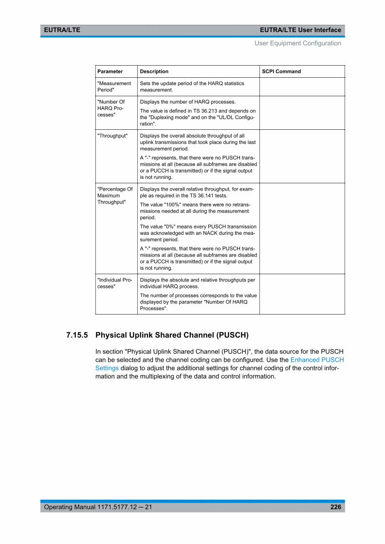
EUTRA/LTE User InterfaceEUTRA/LTE
226Operating Manual 1171.5177.12 ─ 21
Parameter Description SCPI Command
"MeasurementPeriod"
Sets the update period of the HARQ statisticsmeasurement.
"Number OfHARQ Pro-cesses"
Displays the number of HARQ processes.
The value is defined in TS 36.213 and depends onthe "Duplexing mode" and on the "UL/DL Configu-ration".
"Throughput" Displays the overall absolute throughput of alluplink transmissions that took place during the lastmeasurement period.
A "-" represents, that there were no PUSCH trans-missions at all (because all subframes are disabledor a PUCCH is transmitted) or if the signal outputis not running.
"Percentage OfMaximumThroughput"
Displays the overall relative throughput, for exam-ple as required in the TS 36.141 tests.
The value "100%" means there were no retrans-missions needed at all during the measurementperiod.
The value "0%" means every PUSCH transmissionwas acknowledged with an NACK during the mea-surement period.
A "-" represents, that there were no PUSCH trans-missions at all (because all subframes are disabledor a PUCCH is transmitted) or if the signal outputis not running.
"Individual Pro-cesses"
Displays the absolute and relative throughputs perindividual HARQ process.
The number of processes corresponds to the valuedisplayed by the parameter "Number Of HARQProcesses".
7.15.5 Physical Uplink Shared Channel (PUSCH)
In section "Physical Uplink Shared Channel (PUSCH)", the data source for the PUSCHcan be selected and the channel coding can be configured. Use the Enhanced PUSCHSettings dialog to adjust the additional settings for channel coding of the control infor-mation and the multiplexing of the data and control information.
User Equipment Configuration
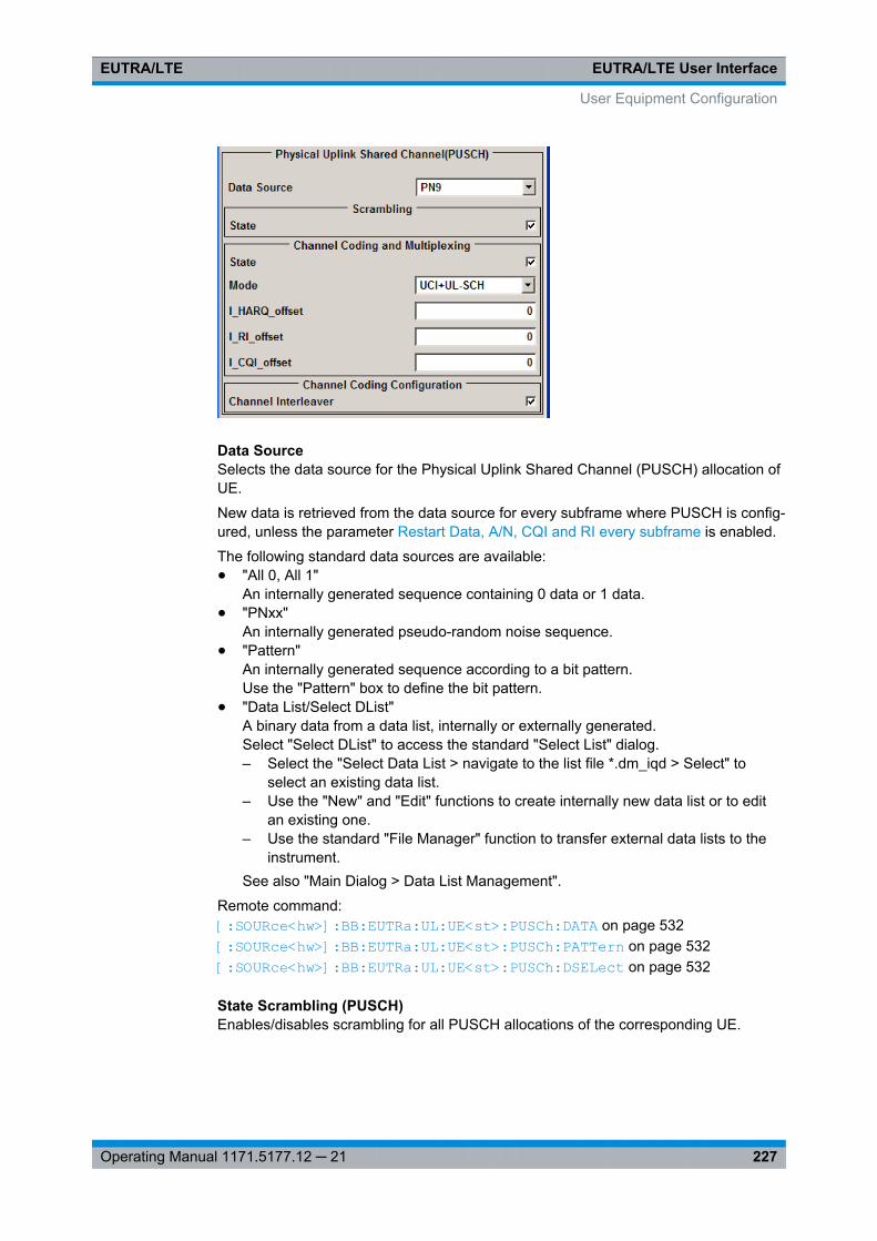
EUTRA/LTE User InterfaceEUTRA/LTE
227Operating Manual 1171.5177.12 ─ 21
Data SourceSelects the data source for the Physical Uplink Shared Channel (PUSCH) allocation ofUE.
New data is retrieved from the data source for every subframe where PUSCH is config-ured, unless the parameter Restart Data, A/N, CQI and RI every subframe is enabled.
The following standard data sources are available:● "All 0, All 1"
An internally generated sequence containing 0 data or 1 data.● "PNxx"
An internally generated pseudo-random noise sequence.● "Pattern"
An internally generated sequence according to a bit pattern.Use the "Pattern" box to define the bit pattern.
● "Data List/Select DList"A binary data from a data list, internally or externally generated.Select "Select DList" to access the standard "Select List" dialog.– Select the "Select Data List > navigate to the list file *.dm_iqd > Select" to
select an existing data list.– Use the "New" and "Edit" functions to create internally new data list or to edit
an existing one.– Use the standard "File Manager" function to transfer external data lists to the
instrument.See also "Main Dialog > Data List Management".
Remote command: [:SOURce<hw>]: BB:EUTRa: UL:UE<st>: PUSCh:DATA on page 532[: SOURce<hw>]: BB:EUTRa: UL:UE<st>: PUSCh:PATTern on page 532[:SOURce<hw>]: BB:EUTRa: UL:UE<st>: PUSCh:DSELect on page 532
State Scrambling (PUSCH)Enables/disables scrambling for all PUSCH allocations of the corresponding UE.
User Equipment Configuration
EUTRA/LTE User InterfaceEUTRA/LTE
228Operating Manual 1171.5177.12 ─ 21
This parameter is always enabled, if a predefined FRC is selected.
Remote command: [:SOURce<hw>]: BB: EUTRa:UL: UE<st>:PUSCh: SCRambling: STATeon page 533
State Channel Coding and Multiplexing (PUSCH)Enables/disables channel coding and multiplexing of data and control information forall PUSCH allocations of the corresponding UE.
If this parameter is disabled, the content retrieved from the Data Source is forwarded tothe scrambler without any coding processing.
Additional parameters for the encoding of control information can be set in EnhancedPUSCH Settings dialog.
This parameter is always enabled, if a predefined FRC is selected.
Remote command: [:SOURce<hw>]: BB: EUTRa:UL: UE<st>:PUSCh: CCODing: STATe on page 533
Mode Channel CodingDefines the information transmitted on the PUSCH.
"UCI+UL-SCH" Control information and data is multiplexed into the PUSCH.
"UL-SCH" Only data is transmitted on PUSCH.
"UCI only" Only uplink control information is transmitted on PUSCH.
Remote command: [:SOURce<hw>]: BB: EUTRa:UL: UE<st>:PUSCh: CCODing: MODE on page 533
I_HARQ_offsetSets the HARQ-ACK offset index for control information MCS offset determinationaccording to 3GPP TS 36.213, chapter 8.6.3.
Remote command: [: SOURce<hw>]: BB:EUTRa: UL:UE<st>: PUSCh:CCODing: IHARqoffset on page 535
I_RI_offsetSets the RI offset index for control information MCS offset determination according to3GPP TS 36.213, chapter 8.6.3.
Remote command: [:SOURce<hw>]: BB: EUTRa:UL: UE<st>:PUSCh: CCODing: IRIoffset on page 535
I_CQI_offsetSets the CQI offset index for control information MCS offset determination according to3GPP TS 36.213, chapter 8.6.3.
Remote command: [:SOURce<hw>]: BB: EUTRa:UL:UE<st>: PUSCh: CCODing: ICQioffseton page 534
User Equipment Configuration
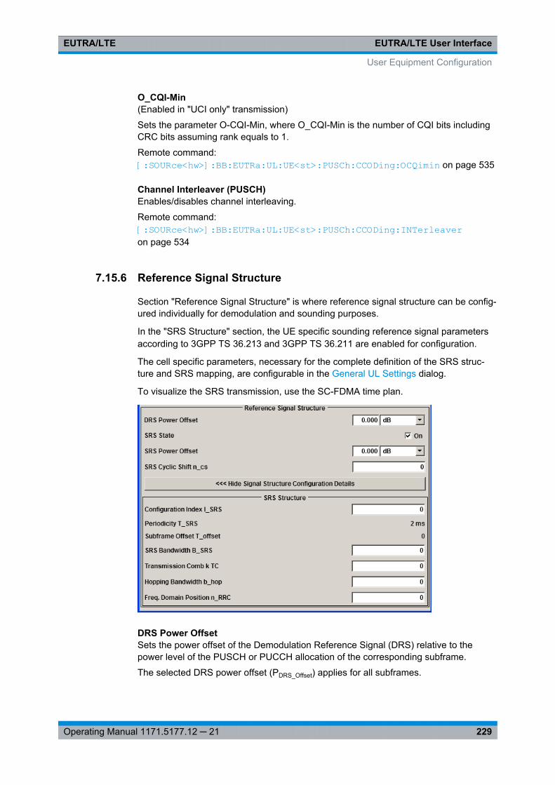
EUTRA/LTE User InterfaceEUTRA/LTE
229Operating Manual 1171.5177.12 ─ 21
O_CQI-Min(Enabled in "UCI only" transmission)
Sets the parameter O-CQI-Min, where O_CQI-Min is the number of CQI bits includingCRC bits assuming rank equals to 1.
Remote command: [:SOURce<hw>]: BB: EUTRa:UL: UE<st>:PUSCh: CCODing: OCQimin on page 535
Channel Interleaver (PUSCH)Enables/disables channel interleaving.
Remote command: [: SOURce<hw>]: BB:EUTRa: UL:UE<st>: PUSCh:CCODing: INTerleaver on page 534
7.15.6 Reference Signal Structure
Section "Reference Signal Structure" is where reference signal structure can be config-ured individually for demodulation and sounding purposes.
In the "SRS Structure" section, the UE specific sounding reference signal parametersaccording to 3GPP TS 36.213 and 3GPP TS 36.211 are enabled for configuration.
The cell specific parameters, necessary for the complete definition of the SRS struc-ture and SRS mapping, are configurable in the General UL Settings dialog.
To visualize the SRS transmission, use the SC-FDMA time plan.
DRS Power OffsetSets the power offset of the Demodulation Reference Signal (DRS) relative to thepower level of the PUSCH or PUCCH allocation of the corresponding subframe.
The selected DRS power offset (PDRS_Offset) applies for all subframes.
User Equipment Configuration
EUTRA/LTE User InterfaceEUTRA/LTE
230Operating Manual 1171.5177.12 ─ 21
Depending on the allocation of the subframe, the effective power level of the DRS iscalculated as following:● for PUSCH allocation
PDRS=PUE+PPUSCH+PDRS_Offset
● for PUCCH allocationPDRS=PUE+PPUCCH+PDRS_Offset
The PUSCH and PUCCH Power levels (PPUSCH and PPUCCH) can vary per subframe.
For global adjustment of the transmit power of the corresponding UE, use the parame-ter UE Power (PUE).
Remote command: [: SOURce<hw>]: BB:EUTRa: UL:UE<st>: REFSig:DRS: POWoffset on page 536
SRS StateEnables/disables sending of SRS for the corresponding UE.
In the symbols reserved for SRS transmission, PUSCH is not transmitted.
Remote command: [:SOURce<hw>]: BB: EUTRa:UL: UE<st>:REFSig: SRS:STATe on page 536
SRS Power OffsetSets the power offset of the Sounding Reference Signal (SRS) relative to the power ofthe corresponding UE.
The selected SRS power offset applies for all subframes.
The effective power level of the SRS is calculated as follow:
PSRS=PUE+PSRS_Offset
For global adjustment of the transmit power of the corresponding UE, use the parame-ter UE Power (PUE).
Remote command: [:SOURce<hw>]: BB: EUTRa:UL: UE<st>:REFSig: SRS:POWoffset on page 536
SRS Cyclic Shift n_CSSets the cyclic shift n_CS used for the generation of the sounding reference signalCAZAC sequence.
Since the different shifts of the same Zadoff-Chu sequence are orthogonal to eachother, applying different SRS cyclic shifts can be used to schedule different users totransmit simultaneously their sounding reference signal.
Remote command: [:SOURce<hw>]: BB:EUTRa:UL: UE<st>:REFSig: SRS: CYCShift on page 536
Show Signal Structure Configuration Details>>>Opens the menu for configuring the sounding reference signal structure.
Remote command: n.a.
User Equipment Configuration
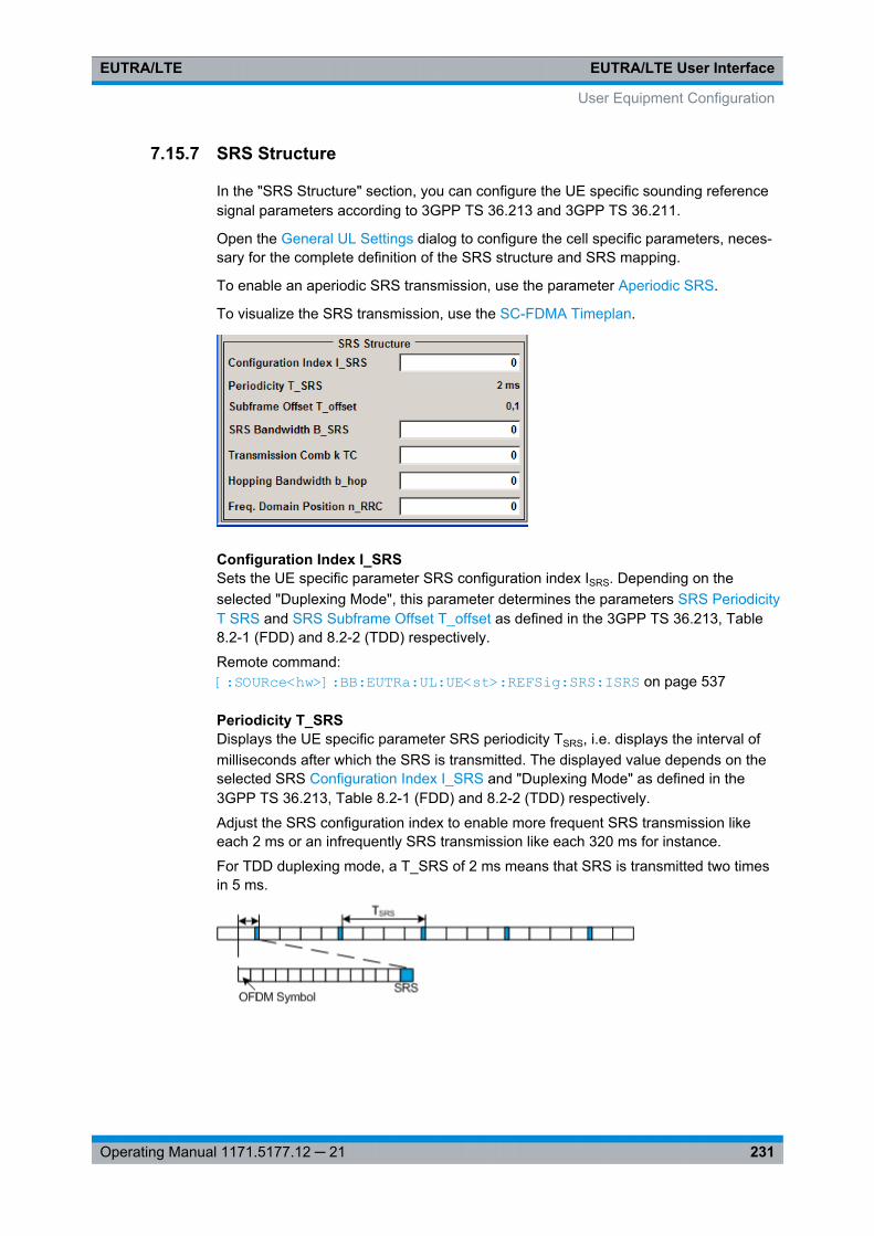
EUTRA/LTE User InterfaceEUTRA/LTE
231Operating Manual 1171.5177.12 ─ 21
7.15.7 SRS Structure
In the "SRS Structure" section, you can configure the UE specific sounding referencesignal parameters according to 3GPP TS 36.213 and 3GPP TS 36.211.
Open the General UL Settings dialog to configure the cell specific parameters, neces-sary for the complete definition of the SRS structure and SRS mapping.
To enable an aperiodic SRS transmission, use the parameter Aperiodic SRS.
To visualize the SRS transmission, use the SC-FDMA Timeplan.
Configuration Index I_SRSSets the UE specific parameter SRS configuration index ISRS. Depending on theselected "Duplexing Mode", this parameter determines the parameters SRS PeriodicityT SRS and SRS Subframe Offset T_offset as defined in the 3GPP TS 36.213, Table8.2-1 (FDD) and 8.2-2 (TDD) respectively.
Remote command: [:SOURce<hw>]: BB:EUTRa: UL:UE<st>: REFSig: SRS:ISRS on page 537
Periodicity T_SRSDisplays the UE specific parameter SRS periodicity TSRS, i.e. displays the interval ofmilliseconds after which the SRS is transmitted. The displayed value depends on theselected SRS Configuration Index I_SRS and "Duplexing Mode" as defined in the3GPP TS 36.213, Table 8.2-1 (FDD) and 8.2-2 (TDD) respectively.
Adjust the SRS configuration index to enable more frequent SRS transmission likeeach 2 ms or an infrequently SRS transmission like each 320 ms for instance.
For TDD duplexing mode, a T_SRS of 2 ms means that SRS is transmitted two timesin 5 ms.
User Equipment Configuration
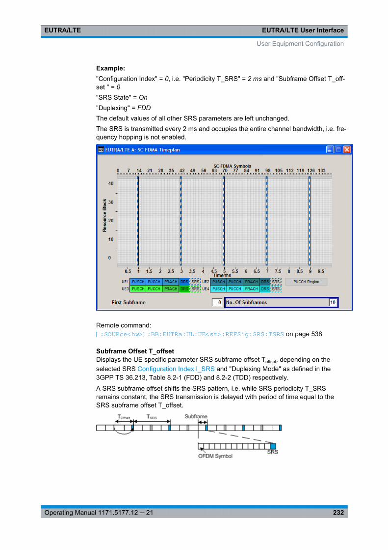
EUTRA/LTE User InterfaceEUTRA/LTE
232Operating Manual 1171.5177.12 ─ 21
Example: "Configuration Index" = 0, i.e. "Periodicity T_SRS" = 2 ms and "Subframe Offset T_off-set " = 0"SRS State" = On"Duplexing" = FDDThe default values of all other SRS parameters are left unchanged.The SRS is transmitted every 2 ms and occupies the entire channel bandwidth, i.e. fre-quency hopping is not enabled.
Remote command: [:SOURce<hw>]: BB: EUTRa:UL: UE<st>:REFSig: SRS:TSRS on page 538
Subframe Offset T_offsetDisplays the UE specific parameter SRS subframe offset Toffset, depending on theselected SRS Configuration Index I_SRS and "Duplexing Mode" as defined in the3GPP TS 36.213, Table 8.2-1 (FDD) and 8.2-2 (TDD) respectively.
A SRS subframe offset shifts the SRS pattern, i.e. while SRS periodicity T_SRSremains constant, the SRS transmission is delayed with period of time equal to theSRS subframe offset T_offset.
User Equipment Configuration
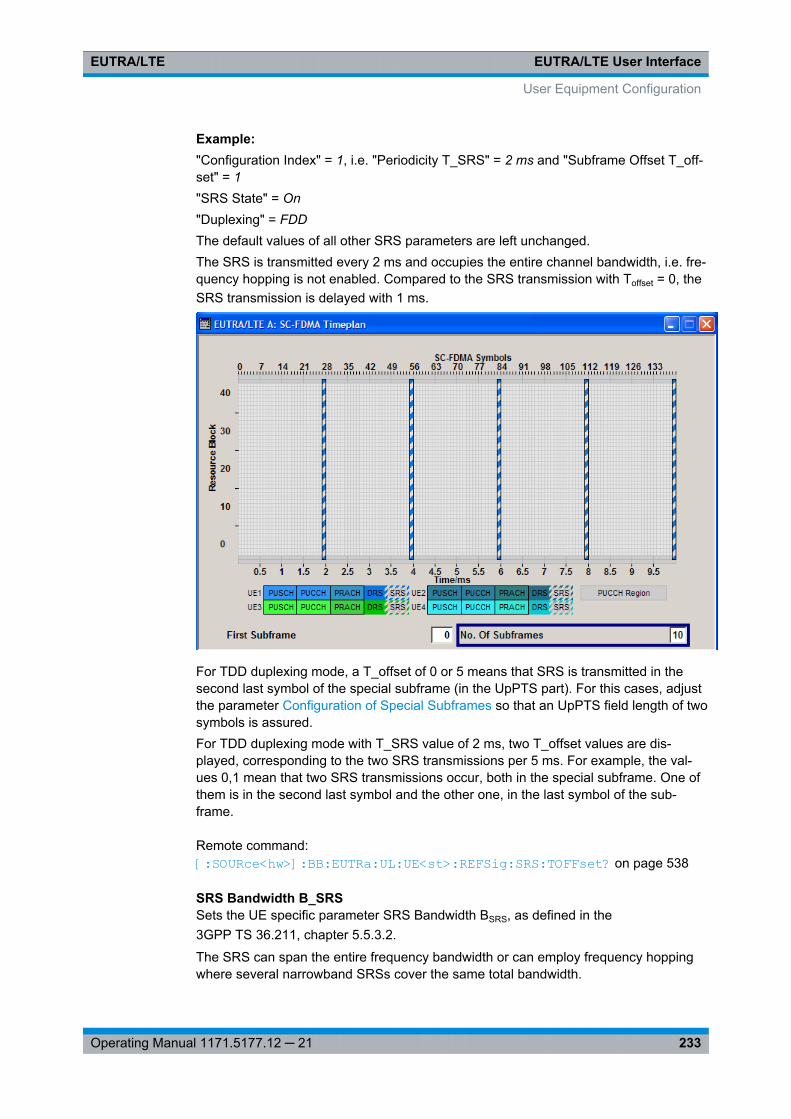
EUTRA/LTE User InterfaceEUTRA/LTE
233Operating Manual 1171.5177.12 ─ 21
Example: "Configuration Index" = 1, i.e. "Periodicity T_SRS" = 2 ms and "Subframe Offset T_off-set" = 1"SRS State" = On"Duplexing" = FDDThe default values of all other SRS parameters are left unchanged.The SRS is transmitted every 2 ms and occupies the entire channel bandwidth, i.e. fre-quency hopping is not enabled. Compared to the SRS transmission with Toffset = 0, theSRS transmission is delayed with 1 ms.
For TDD duplexing mode, a T_offset of 0 or 5 means that SRS is transmitted in thesecond last symbol of the special subframe (in the UpPTS part). For this cases, adjustthe parameter Configuration of Special Subframes so that an UpPTS field length of twosymbols is assured.For TDD duplexing mode with T_SRS value of 2 ms, two T_offset values are dis-played, corresponding to the two SRS transmissions per 5 ms. For example, the val-ues 0,1 mean that two SRS transmissions occur, both in the special subframe. One ofthem is in the second last symbol and the other one, in the last symbol of the sub-frame.
Remote command: [:SOURce<hw>]: BB: EUTRa:UL: UE<st>:REFSig: SRS:TOFFset? on page 538
SRS Bandwidth B_SRSSets the UE specific parameter SRS Bandwidth BSRS, as defined in the3GPP TS 36.211, chapter 5.5.3.2.
The SRS can span the entire frequency bandwidth or can employ frequency hoppingwhere several narrowband SRSs cover the same total bandwidth.
User Equipment Configuration
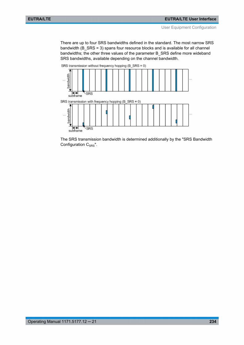
EUTRA/LTE User InterfaceEUTRA/LTE
234Operating Manual 1171.5177.12 ─ 21
There are up to four SRS bandwidths defined in the standard. The most narrow SRSbandwidth (B_SRS = 3) spans four resource blocks and is available for all channelbandwidths; the other three values of the parameter B_SRS define more widebandSRS bandwidths, available depending on the channel bandwidth.
The SRS transmission bandwidth is determined additionally by the "SRS BandwidthConfiguration CSRS".
User Equipment Configuration
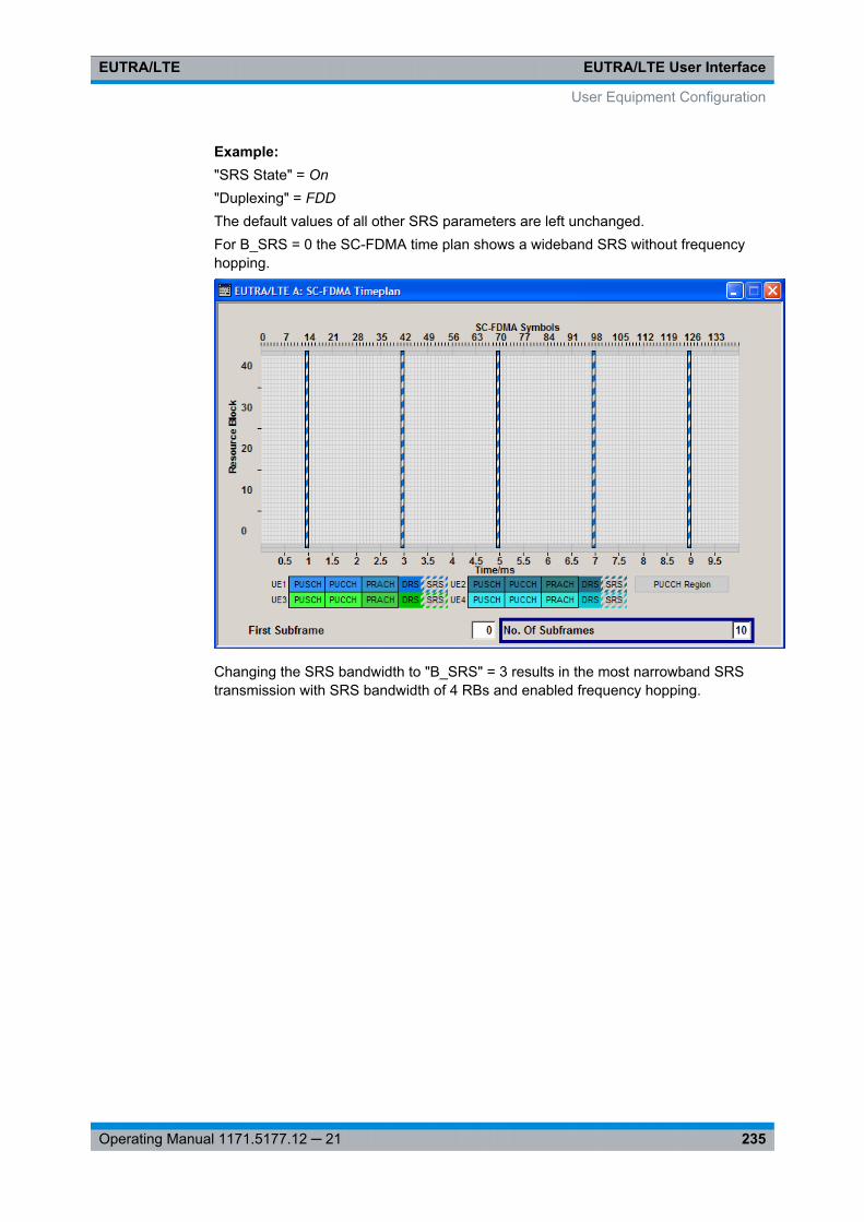
EUTRA/LTE User InterfaceEUTRA/LTE
235Operating Manual 1171.5177.12 ─ 21
Example: "SRS State" = On"Duplexing" = FDDThe default values of all other SRS parameters are left unchanged.For B_SRS = 0 the SC-FDMA time plan shows a wideband SRS without frequencyhopping.
Changing the SRS bandwidth to "B_SRS" = 3 results in the most narrowband SRStransmission with SRS bandwidth of 4 RBs and enabled frequency hopping.
User Equipment Configuration
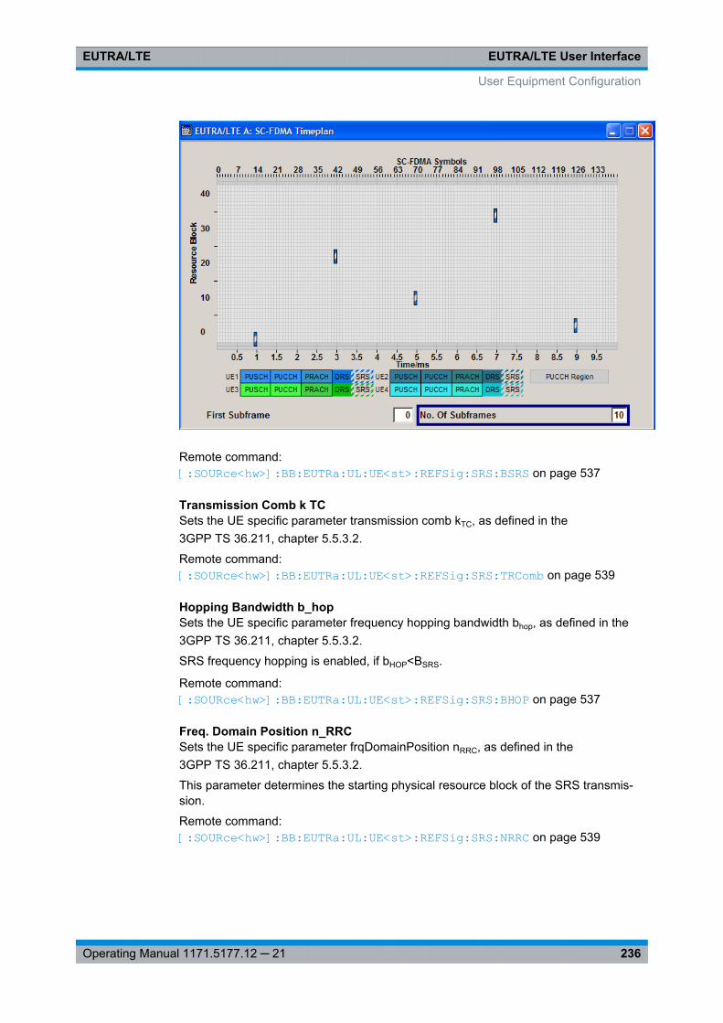
EUTRA/LTE User InterfaceEUTRA/LTE
236Operating Manual 1171.5177.12 ─ 21
Remote command: [:SOURce<hw>]: BB: EUTRa:UL: UE<st>:REFSig: SRS:BSRS on page 537
Transmission Comb k TCSets the UE specific parameter transmission comb kTC, as defined in the3GPP TS 36.211, chapter 5.5.3.2.
Remote command: [:SOURce<hw>]: BB:EUTRa: UL:UE<st>:REFSig: SRS: TRComb on page 539
Hopping Bandwidth b_hopSets the UE specific parameter frequency hopping bandwidth bhop, as defined in the3GPP TS 36.211, chapter 5.5.3.2.
SRS frequency hopping is enabled, if bHOP<BSRS.
Remote command: [:SOURce<hw>]: BB: EUTRa:UL:UE<st>: REFSig: SRS:BHOP on page 537
Freq. Domain Position n_RRCSets the UE specific parameter frqDomainPosition nRRC, as defined in the3GPP TS 36.211, chapter 5.5.3.2.
This parameter determines the starting physical resource block of the SRS transmis-sion.
Remote command: [:SOURce<hw>]: BB:EUTRa:UL: UE<st>:REFSig: SRS:NRRC on page 539
User Equipment Configuration
EUTRA/LTE User InterfaceEUTRA/LTE
237Operating Manual 1171.5177.12 ─ 21
7.15.8 PRACH Power Ramping
The "PRACH" settings are available when the user equipment "Mode" is set toPRACH.
State PRACH Power RampingActivates Power Ramping for the PRACH preamble. The start and the end of the pre-amble is cyclically extended and multiplied with a ramping function (sin^2).
Remote command: [:SOURce<hw>]: BB:EUTRa:UL: UE<st>:PRACh: PRSTate on page 528
Transition TimeDefines the transition time from beginning of the extended preamble to the start of thepreamble itself.
Remote command: [:SOURce<hw>]: BB: EUTRa:UL:UE<st>: PRACh: PRTT on page 528
7.15.9 PRACH Configuration
The "PRACH" settings are available when the user equipment "Mode" is set toPRACH.
In the "PRACH Configuration" section, the UE specific parameters according to3GPP TS 36.211 are enabled for configuration.
The cell specific parameters, necessary for the complete definition of the PRACH, areconfigurable in the General UL Settings dialog.
Preamble Format (Burst Format)Displays the preamble format.
The "Preamble Format" is automatically derived form the PRACH Configuration.
Remote command: [:SOURce<hw>]: BB: EUTRa:UL:UE<st>: PRACh: PRFormat on page 529
Number of Configurable FramesShows how many frames can be configured.
A maximum number of 20 frames are available for configuration; the currently availablenumber of frames depends on the selected ARB Sequence Length.
Remote command: [:SOURce<hw>]: BB: EUTRa:UL: UE<st>:PRACh: CFRames on page 529
SFDisplays the consecutive number of the subframe.
The subframes available for configuration depend on the selected "Duplexing" modeand "PRACH Configuration".
Remote command: n.a.
User Equipment Configuration
EUTRA/LTE User InterfaceEUTRA/LTE
238Operating Manual 1171.5177.12 ─ 21
RB OffsetDisplays the starting RB, as set with the parameter PRACH Frequency Offset.
Remote command: [:SOURce<hw>]: BB:EUTRa:UL: UE<st>:PRACh: SUBF<ch0>: RBOFfset on page 529
Frequency Resource IndexThis parameter is enabled in TDD duplexing mode only.
Sets the frequency resource index fRA for the selected subframe.
Remote command: [:SOURce<hw>]: BB:EUTRa: UL:UE<st>: PRACh:SUBF<ch0>: FRINdex on page 530
Ncs ConfigurationSelects the Ncs configuration of the selected subframe, i.e. determines the Ncs valuefor the selected preamble set according to TS 36.211, table 5.7.2.-2 and 5.7.2-3.
The value range of this parameter depends on the selected Duplexing mode, PRACHconfiguration and whether a restricted preamble set is enabled or not.
Parameter Value Range Ncs Configuration
Disabled Restricted Set (High Speed Mode) 0 .. 15
Enabled "Restricted Preamble Set" 0 .. 14
TDD + PRACH Configuration > 47 0 .. 6
Remote command: [:SOURce<hw>]: BB: EUTRa:UL: UE<st>:PRACh: SUBF<ch0>: NCSConfon page 530
Logical Root Sequence IndexSelects the logical root sequence index for the selected subframe.
The value range of this parameter depends on the combination of selected Duplexingmode and PRACH configuration.
Parameter Value Range Logical Root SequenceIndex
TDD + PRACH Configuration > 47 i.e. Preamble Format 4 0 .. 137
All other cases 0 .. 837
Remote command: [:SOURce<hw>]: BB: EUTRa:UL: UE<st>:PRACh: SUBF<ch0>: RSEQuence on page 531
User Equipment Configuration
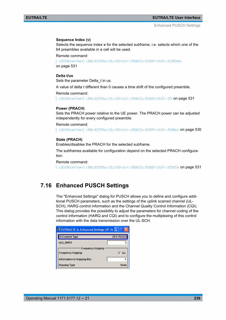
EUTRA/LTE User InterfaceEUTRA/LTE
239Operating Manual 1171.5177.12 ─ 21
Sequence Index (v)Selects the sequence index v for the selected subframe, i.e. selects which one of the64 preambles available in a cell will be used.
Remote command: [:SOURce<hw>]: BB:EUTRa: UL:UE<st>: PRACh: SUBF<ch0>: SINDexon page 531
Delta t/usSets the parameter Delta_t in us.
A value of delta t different than 0 causes a time shift of the configured preamble.
Remote command: [:SOURce<hw>]: BB:EUTRa: UL:UE<st>: PRACh: SUBF<ch0>: DT on page 531
Power (PRACH)Sets the PRACH power relative to the UE power. The PRACH power can be adjustedindependently for every configured preamble.
Remote command: [: SOURce<hw>]: BB:EUTRa: UL:UE<st>: PRACh:SUBF<ch0>: POWer on page 530
State (PRACH)Enables/disables the PRACH for the selected subframe.
The subframes available for configuration depend on the selected PRACH configura-tion.
Remote command: [: SOURce<hw>]: BB:EUTRa: UL:UE<st>: PRACh:SUBF<ch0>: STATe on page 531
7.16 Enhanced PUSCH Settings
The "Enhanced Settings" dialog for PUSCH allows you to define and configure addi-tional PUSCH parameters, such as the settings of the uplink scarred channel (UL-SCH), HARQ control information and the Channel Quality Control Information (CQI).This dialog provides the possibility to adjust the parameters for channel coding of thecontrol information (HARQ and CQI) and to configure the multiplexing of this controlinformation with the data transmission over the UL-SCH.
Enhanced PUSCH Settings
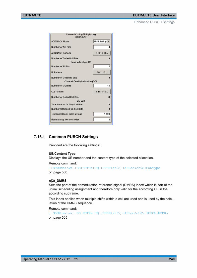
EUTRA/LTE User InterfaceEUTRA/LTE
240Operating Manual 1171.5177.12 ─ 21
7.16.1 Common PUSCH Settings
Provided are the following settings:
UE/Content TypeDisplays the UE number and the content type of the selected allocation.
Remote command: [:SOURce<hw>]: BB:EUTRa: UL[:SUBF<st0>]: ALLoc<ch0>: CONTypeon page 500
n(2)_DMRSSets the part of the demodulation reference signal (DMRS) index which is part of theuplink scheduling assignment and therefore only valid for the according UE in theaccording subframe.
This index applies when multiple shifts within a cell are used and is used by the calcu-lation of the DMRS sequence.
Remote command: [: SOURce<hw>]: BB:EUTRa: UL[:SUBF<st0>]: ALLoc<ch0>: PUSCh: NDMRson page 505
Enhanced PUSCH Settings
EUTRA/LTE User InterfaceEUTRA/LTE
241Operating Manual 1171.5177.12 ─ 21
7.16.2 Frequency Hopping
Frequency HoppingEnables/disables frequency hopping for PUSCH.
Frequency hopping is applied according to 3GPP TS 36.213.
Based on the Information in Hopping Bits, a UE performing PUSCH frequency hoppingapplies one of the two possible Hopping Type.
Remote command: [: SOURce<hw>]: BB:EUTRa: UL[:SUBF<st0>]: ALLoc<ch0>: PUSCh: FHOP:STATe on page 505
Information in Hopping BitsSets the information in hopping bits according to the PDCCH DCI format 0 hopping bitdefinition. This information determines whether type 1 or type 2 hopping is used in thesubframe, and - in case of type 1 - additionally determines the exact hopping functionto use.
Frequency hopping is applied according to 3GPP TS 36.213.
Remote command: [: SOURce<hw>]: BB:EUTRa: UL[:SUBF<st0>]: ALLoc<ch0>: PUSCh: FHOP:IIHBits on page 506
Hopping TypeDisplays the frequency hopping type used, as defined in 3GPP TS 36.213.
Remote command: [: SOURce<hw>]: BB:EUTRa: UL[:SUBF<st0>]: ALLoc<ch0>: PUSCh: FHOP:TYPE on page 505
7.16.3 Channel Coding / Multiplexing
All parameters in this section are enabled for configuration only if the Channel Codingfor the corresponding user equipment is activated and the Mode Channel Coding is setto "UCI+UL-SCH" or "UCI Only".
ACK/NACK ModeSets the ACK/NACK mode to Multiplexing or Bundling according to 3GPP TS 36.212,chapter 5.2.2.6.
ACK/NACK mode Bundling is defined for TDD duplexing mode only.
Remote command: [:SOURce<hw>]: BB:EUTRa: UL[:SUBF<st0>]: ALLoc<ch0>: PUSCh:HARQ: MODEon page 506
Enhanced PUSCH Settings
EUTRA/LTE User InterfaceEUTRA/LTE
242Operating Manual 1171.5177.12 ─ 21
N_bundledFor "ACK/NACK Mode Bundling", sets the parameter N_bundled according to 3GPPTS36.212, section 5.2.2.6.
Remote command: [:SOURce<hw>]: BB: EUTRa:UL[: SUBF<st0>]: ALLoc<ch0>: PUSCh:HARQ: NBUNdled on page 506
Number of A/N BitsSets the number of ACK/NACK bits.
Set this parameter to 0 to deactivate the ACK/NACK transmission for the correspond-ing subframe.
Remote command: [:SOURce<hw>]: BB: EUTRa:UL[: SUBF<st0>]: ALLoc<ch0>: PUSCh:HARQ: BITSon page 507
ACK/NACK PatternSets the ACK/NACK bits in form of a 64 bits long pattern.
A "1" indicates an ACK, a "0" - a NACK.
The pattern is read out cyclically and if the pattern is longer than the selected "Numberof ACK/NACK Bits", different bits will be transmitted in different subframes using thisconfiguration.
Remote command: [:SOURce<hw>]: BB: EUTRa:UL[: SUBF<st0>]: ALLoc<ch0>: PUSCh:HARQ: PATTern on page 507
Number of Coded A/N BitsDisplays the number of coded ACK/NACK bits.
Remote command: [:SOURce<hw>]: BB:EUTRa: UL[: SUBF<st0>]: ALLoc<ch0>: PUSCh: HARQ:CBITs on page 507
Number of RI BitsSets the number of rank indication (RI) bits.
Set this parameter to 0 to deactivate the RI for the corresponding subframe.
Remote command: [: SOURce<hw>]: BB:EUTRa: UL[:SUBF<st0>]: ALLoc<ch0>: PUSCh: RI:BITSon page 509
RI PatternSets the RI bits in form of a 64 bits long pattern.
Enhanced PUSCH Settings
EUTRA/LTE User InterfaceEUTRA/LTE
243Operating Manual 1171.5177.12 ─ 21
The pattern is read out cyclically and if the pattern is longer than the selected "Numberof RI Bits", different bits will be transmitted in different subframes using this configura-tion.
Remote command: [:SOURce<hw>]: BB:EUTRa: UL[:SUBF<st0>]: ALLoc<ch0>: PUSCh: RI:PATTern on page 509
Number of Coded RI BitsDisplays the number of coded RI bits.
If a "Channel Coding Mode UCI + UL-SCH" is selected, the Number of Physical Bits forUL-SCH is determinate by the number of coded bits used for CQI and RI transmission.
Remote command: [:SOURce<hw>]: BB: EUTRa:UL[: SUBF<st0>]: ALLoc<ch0>: PUSCh:RI: CBITs?on page 509
Number of CQI BitsSets the number of CQI bits before channel coding.
If a "Channel Coding Mode UCI + UL-SCH" is selected, the Number of Physical Bits forUL-SCH is determinate by the number of coded bits used for CQI and RI transmission.
Remote command: [: SOURce<hw>]: BB:EUTRa: UL[:SUBF<st0>]: ALLoc<ch0>: PUSCh: CQI:BITS on page 508
CQI PatternSets the CQI pattern for the PUSCH.
The pattern is read out cyclically and if the pattern is longer than the selected "Numberof CQI Bits", different bits will be transmitted in different subframes using this configu-ration.
Remote command: [: SOURce<hw>]: BB:EUTRa: UL[:SUBF<st0>]: ALLoc<ch0>: PUSCh: CQI:PATTern on page 508
Number of Coded CQI BitsDisplays the number of coded CQI bits.
Remote command: [:SOURce<hw>]: BB: EUTRa:UL[: SUBF<st0>]: ALLoc<ch0>: PUSCh:CQI: CBITs? on page 508
Enhanced PUSCH Settings
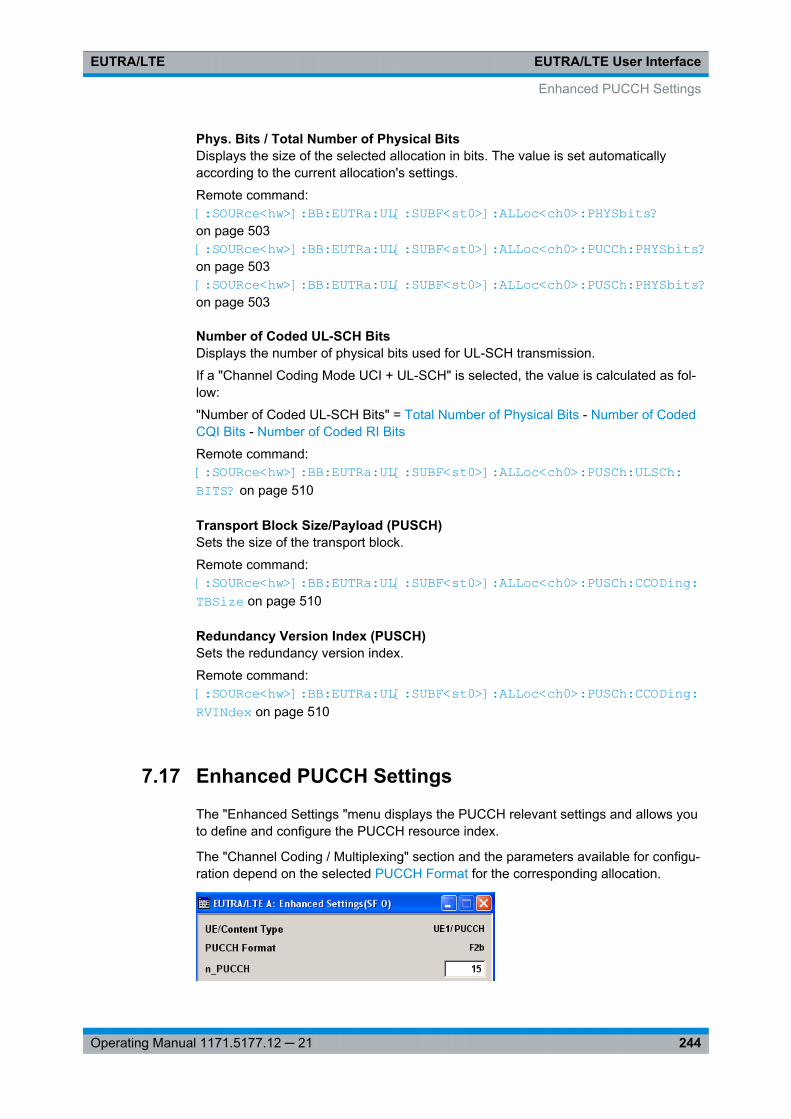
EUTRA/LTE User InterfaceEUTRA/LTE
244Operating Manual 1171.5177.12 ─ 21
Phys. Bits / Total Number of Physical BitsDisplays the size of the selected allocation in bits. The value is set automaticallyaccording to the current allocation's settings.
Remote command: [:SOURce<hw>]: BB:EUTRa: UL[:SUBF<st0>]: ALLoc<ch0>: PHYSbits? on page 503[:SOURce<hw>]: BB:EUTRa: UL[:SUBF<st0>]: ALLoc<ch0>: PUCCh: PHYSbits? on page 503[:SOURce<hw>]: BB:EUTRa: UL[:SUBF<st0>]: ALLoc<ch0>: PUSCh: PHYSbits? on page 503
Number of Coded UL-SCH BitsDisplays the number of physical bits used for UL-SCH transmission.
If a "Channel Coding Mode UCI + UL-SCH" is selected, the value is calculated as fol-low:
"Number of Coded UL-SCH Bits" = Total Number of Physical Bits - Number of CodedCQI Bits - Number of Coded RI Bits
Remote command: [:SOURce<hw>]: BB:EUTRa: UL[:SUBF<st0>]: ALLoc<ch0>: PUSCh:ULSCh: BITS? on page 510
Transport Block Size/Payload (PUSCH)Sets the size of the transport block.
Remote command: [:SOURce<hw>]: BB: EUTRa:UL[: SUBF<st0>]: ALLoc<ch0>: PUSCh:CCODing: TBSize on page 510
Redundancy Version Index (PUSCH)Sets the redundancy version index.
Remote command: [:SOURce<hw>]: BB:EUTRa:UL[: SUBF<st0>]: ALLoc<ch0>: PUSCh: CCODing:RVINdex on page 510
7.17 Enhanced PUCCH Settings
The "Enhanced Settings "menu displays the PUCCH relevant settings and allows youto define and configure the PUCCH resource index.
The "Channel Coding / Multiplexing" section and the parameters available for configu-ration depend on the selected PUCCH Format for the corresponding allocation.
Enhanced PUCCH Settings
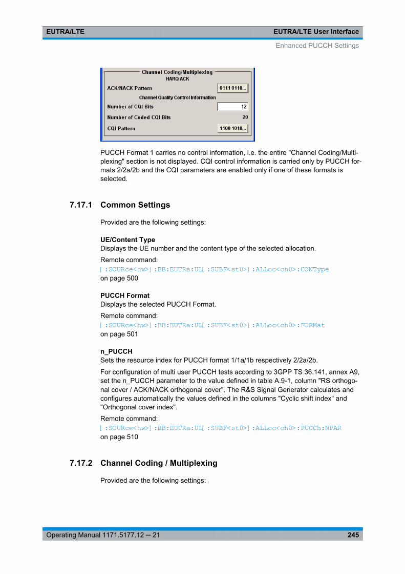
EUTRA/LTE User InterfaceEUTRA/LTE
245Operating Manual 1171.5177.12 ─ 21
PUCCH Format 1 carries no control information, i.e. the entire "Channel Coding/Multi-plexing" section is not displayed. CQI control information is carried only by PUCCH for-mats 2/2a/2b and the CQI parameters are enabled only if one of these formats isselected.
7.17.1 Common Settings
Provided are the following settings:
UE/Content TypeDisplays the UE number and the content type of the selected allocation.
Remote command: [:SOURce<hw>]: BB:EUTRa: UL[:SUBF<st0>]: ALLoc<ch0>: CONTypeon page 500
PUCCH FormatDisplays the selected PUCCH Format.
Remote command: [:SOURce<hw>]: BB:EUTRa:UL[: SUBF<st0>]: ALLoc<ch0>: FORMat on page 501
n_PUCCHSets the resource index for PUCCH format 1/1a/1b respectively 2/2a/2b.
For configuration of multi user PUCCH tests according to 3GPP TS 36.141, annex A9,set the n_PUCCH parameter to the value defined in table A.9-1, column "RS orthogo-nal cover / ACK/NACK orthogonal cover". The R&S Signal Generator calculates andconfigures automatically the values defined in the columns "Cyclic shift index" and"Orthogonal cover index".
Remote command: [: SOURce<hw>]: BB:EUTRa: UL[:SUBF<st0>]: ALLoc<ch0>: PUCCh: NPARon page 510
7.17.2 Channel Coding / Multiplexing
Provided are the following settings:
Enhanced PUCCH Settings
EUTRA/LTE User InterfaceEUTRA/LTE
246Operating Manual 1171.5177.12 ─ 21
ACK/NACK Pattern / ACK/NACK+SR Pattern("ACK/NACK Pattern" is enabled for PUCCH formats 1a/1b, 2a/2b; "ACK/NACK+SRPattern" for PUCCH format 3)
Use this parameter to set the ACK/NACK pattern for the PUCCH for the selected sub-frame. A "1" indicates an ACK, a "0" - a NACK
In PUCCH format 3, the bits given by the ACK/NACK+SR PATTERN represent theoACK bits according to 3GPP TS 36.212, i.e. the up to 21 bits that contain ACK/NACKinformation for up to two codewords and optionally SR. The number of bits used persubframe is determinate by the value of the parameter "Number of ACK/NACK+SRBits" on page 248.
To enable the generation of signals with ACK/NACK respectively ACK/NACK+SR infor-mation that varies not only per subframe but also differs over the frames, set a patternwith● more than 1 bit for the PUCCH formats 1a/2a● more than 2 bits for the PUCCH formats 1b/2b● more than "Number of ACK/NACK+SR Bits" on page 248 for PUCCH format 3The ACK/NACK pattern has a maximal length of 32 bits and is read out cyclically.
Enhanced PUCCH Settings
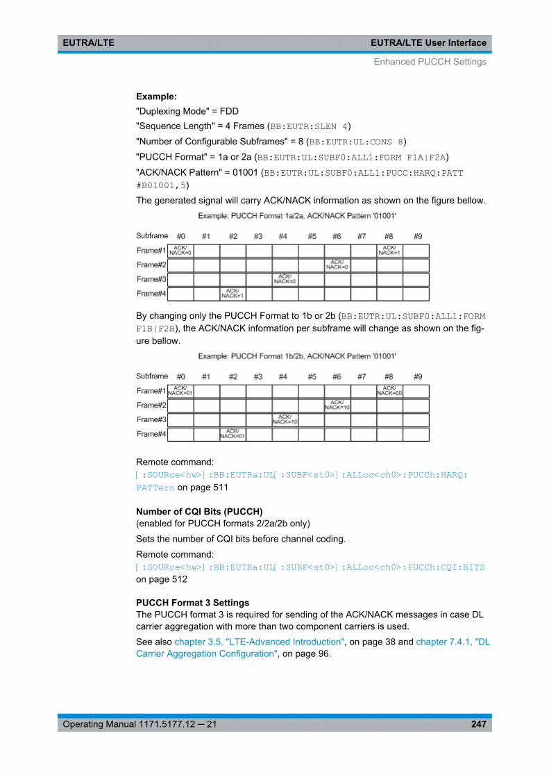
EUTRA/LTE User InterfaceEUTRA/LTE
247Operating Manual 1171.5177.12 ─ 21
Example: "Duplexing Mode" = FDD"Sequence Length" = 4 Frames (BB:EUTR:SLEN 4)
"Number of Configurable Subframes" = 8 (BB:EUTR:UL:CONS 8)
"PUCCH Format" = 1a or 2a (BB:EUTR:UL:SUBF0:ALL1:FORM F1A|F2A)
"ACK/NACK Pattern" = 01001 (BB:EUTR:UL:SUBF0:ALL1:PUCC:HARQ:PATT#B01001,5)
The generated signal will carry ACK/NACK information as shown on the figure bellow.
By changing only the PUCCH Format to 1b or 2b (BB:EUTR:UL:SUBF0:ALL1:FORMF1B|F2B), the ACK/NACK information per subframe will change as shown on the fig-ure bellow.
Remote command: [:SOURce<hw>]: BB: EUTRa:UL[: SUBF<st0>]: ALLoc<ch0>: PUCCh:HARQ: PATTern on page 511
Number of CQI Bits (PUCCH)(enabled for PUCCH formats 2/2a/2b only)
Sets the number of CQI bits before channel coding.
Remote command: [:SOURce<hw>]: BB:EUTRa: UL[:SUBF<st0>]: ALLoc<ch0>: PUCCh:CQI: BITSon page 512
PUCCH Format 3 SettingsThe PUCCH format 3 is required for sending of the ACK/NACK messages in case DLcarrier aggregation with more than two component carriers is used.
See also chapter 3.5, "LTE-Advanced Introduction", on page 38 and chapter 7.4.1, "DLCarrier Aggregation Configuration", on page 96.
Enhanced PUCCH Settings
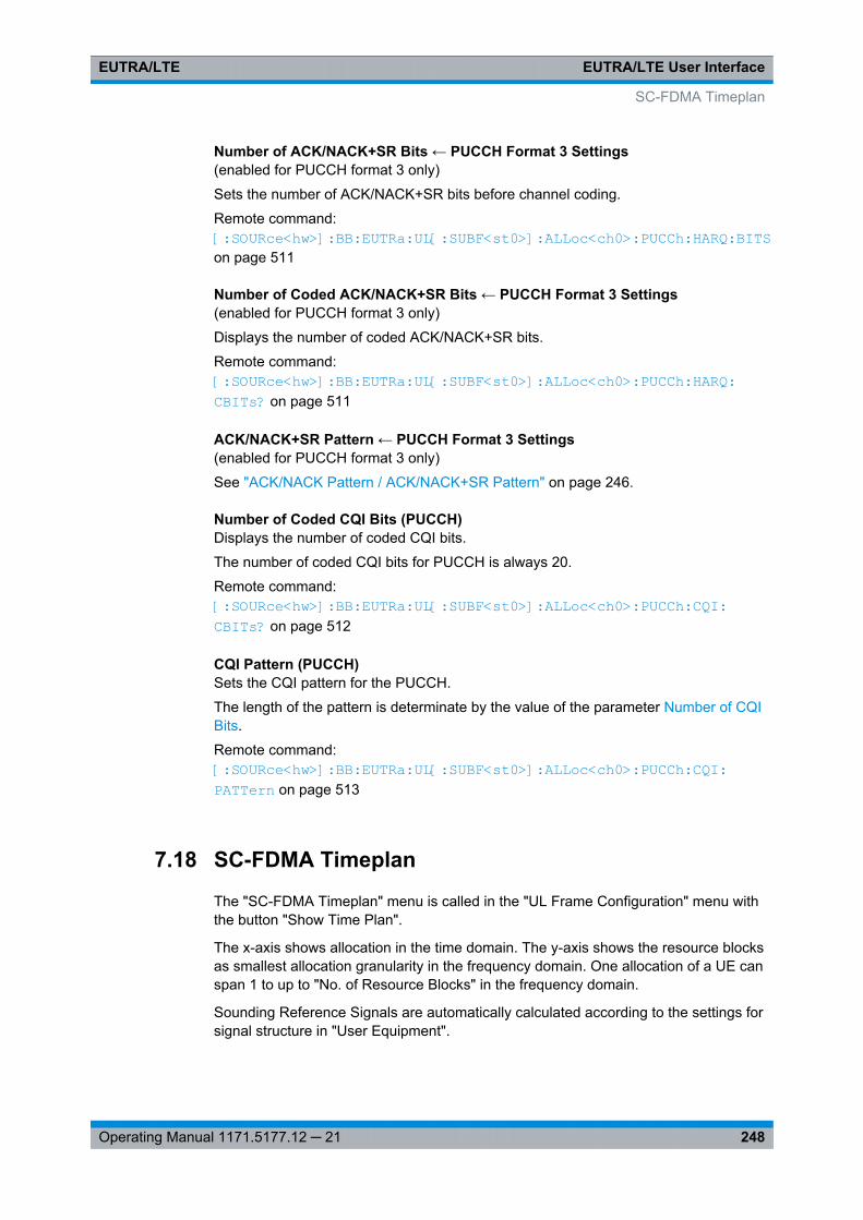
EUTRA/LTE User InterfaceEUTRA/LTE
248Operating Manual 1171.5177.12 ─ 21
Number of ACK/NACK+SR Bits ← PUCCH Format 3 Settings(enabled for PUCCH format 3 only)
Sets the number of ACK/NACK+SR bits before channel coding.
Remote command: [: SOURce<hw>]: BB:EUTRa: UL[:SUBF<st0>]: ALLoc<ch0>: PUCCh: HARQ:BITS on page 511
Number of Coded ACK/NACK+SR Bits ← PUCCH Format 3 Settings(enabled for PUCCH format 3 only)
Displays the number of coded ACK/NACK+SR bits.
Remote command: [:SOURce<hw>]: BB:EUTRa: UL[:SUBF<st0>]: ALLoc<ch0>: PUCCh: HARQ: CBITs? on page 511
ACK/NACK+SR Pattern ← PUCCH Format 3 Settings(enabled for PUCCH format 3 only)
See "ACK/NACK Pattern / ACK/NACK+SR Pattern" on page 246.
Number of Coded CQI Bits (PUCCH)Displays the number of coded CQI bits.
The number of coded CQI bits for PUCCH is always 20.
Remote command: [: SOURce<hw>]: BB:EUTRa: UL[:SUBF<st0>]: ALLoc<ch0>: PUCCh: CQI:CBITs? on page 512
CQI Pattern (PUCCH)Sets the CQI pattern for the PUCCH.
The length of the pattern is determinate by the value of the parameter Number of CQIBits.
Remote command: [:SOURce<hw>]: BB: EUTRa:UL[: SUBF<st0>]: ALLoc<ch0>: PUCCh:CQI: PATTern on page 513
7.18 SC-FDMA Timeplan
The "SC-FDMA Timeplan" menu is called in the "UL Frame Configuration" menu withthe button "Show Time Plan".
The x-axis shows allocation in the time domain. The y-axis shows the resource blocksas smallest allocation granularity in the frequency domain. One allocation of a UE canspan 1 to up to "No. of Resource Blocks" in the frequency domain.
Sounding Reference Signals are automatically calculated according to the settings forsignal structure in "User Equipment".
SC-FDMA Timeplan
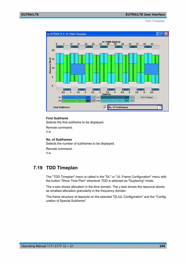
EUTRA/LTE User InterfaceEUTRA/LTE
249Operating Manual 1171.5177.12 ─ 21
First SubframeSelects the first subframe to be displayed.
Remote command: n.a.
No. of SubframesSelects the number of subframes to be displayed.
Remote command: n.a.
7.19 TDD Timeplan
The "TDD Timeplan" menu is called in the "DL" or "UL Frame Configuration" menu withthe button "Show Time Plan" whenever TDD is selected as "Duplexing" mode.
The x-axis shows allocation in the time domain. The y-axis shows the resource blocksas smallest allocation granularity in the frequency domain.
The frame structure of depends on the selected "DL/UL Configuration" and the "Config-uration of Special Subframe".
TDD Timeplan
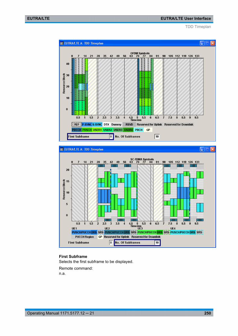
EUTRA/LTE User InterfaceEUTRA/LTE
250Operating Manual 1171.5177.12 ─ 21
First SubframeSelects the first subframe to be displayed.
Remote command: n.a.
TDD Timeplan
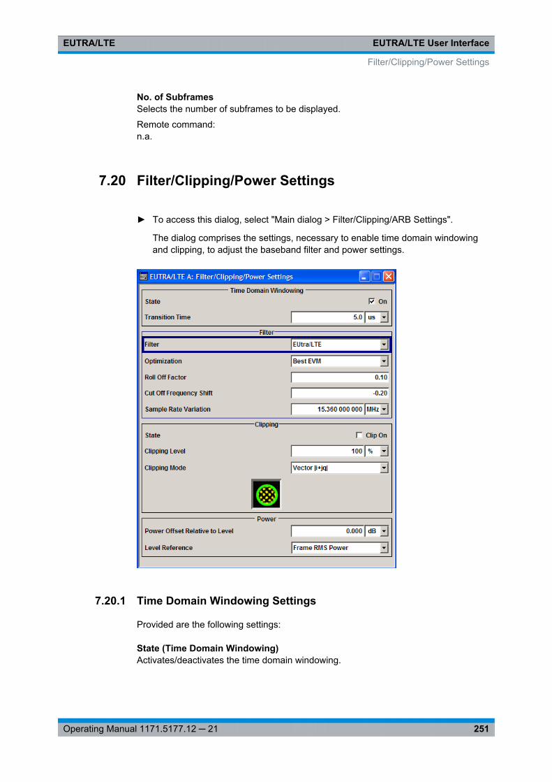
EUTRA/LTE User InterfaceEUTRA/LTE
251Operating Manual 1171.5177.12 ─ 21
No. of SubframesSelects the number of subframes to be displayed.
Remote command: n.a.
7.20 Filter/Clipping/Power Settings
► To access this dialog, select "Main dialog > Filter/Clipping/ARB Settings".
The dialog comprises the settings, necessary to enable time domain windowingand clipping, to adjust the baseband filter and power settings.
7.20.1 Time Domain Windowing Settings
Provided are the following settings:
State (Time Domain Windowing)Activates/deactivates the time domain windowing.
Filter/Clipping/Power Settings
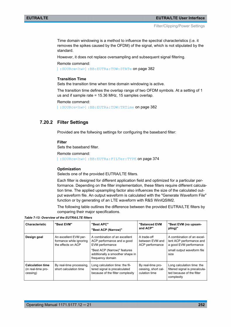
EUTRA/LTE User InterfaceEUTRA/LTE
252Operating Manual 1171.5177.12 ─ 21
Time domain windowing is a method to influence the spectral characteristics (i.e. itremoves the spikes caused by the OFDM) of the signal, which is not stipulated by thestandard.
However, it does not replace oversampling and subsequent signal filtering.
Remote command: [:SOURce<hw>]: BB:EUTRa: TDW:STATe on page 382
Transition TimeSets the transition time when time domain windowing is active.
The transition time defines the overlap range of two OFDM symbols. At a setting of 1us and if sample rate = 15.36 MHz, 15 samples overlap.
Remote command: [:SOURce<hw>]: BB:EUTRa:TDW: TRTime on page 382
7.20.2 Filter Settings
Provided are the follwoing settings for configuring the baseband filter:
FilterSets the baseband filter.
Remote command: [:SOURce<hw>]: BB:EUTRa: FILTer:TYPE on page 374
OptimizationSelects one of the provided EUTRA/LTE filters.
Each filter is designed for different application field and optimized for a particular per-formance. Depending on the filter implementation, these filters require different calcula-tion time. The applied upsampling factor also influences the size of the calculated out-put waveform file. An output waveform is calculated with the "Generate Waveform File"function or by generating of an LTE waveform with R&S WinIQSIM2.
The following table outlines the difference between the provided EUTRA/LTE filters bycomparing their major specifications.
Table 7-13: Overview of the EUTRA/LTE filters
Characteristic "Best EVM" "Best APC"
"Best ACP (Narrow)"
"Balanced EVMand ACP"
"Best EVM (no upsam-pling)"
Design goal An excellent EVM per-formance while ignoringthe effects on ACP
A combination of an excellentACP performance and a goodEVM performance
"Best ACP (Narrow)" featuresadditionally a smoother shape infrequency domain
A trade-offbetween EVM andACP performance
A combination of an excel-lent ACP performance anda good EVM performance
small output waveform filesize
Calculation time(in real-time pro-cessing)
By real-time processing,short calculation time
Long calculation time: the fil-tered signal is precalculatedbecause of the filter complexity
By real-time pro-cessing, short cal-culation time
Long calculation time: thefiltered signal is precalcula-ted because of the filtercomplexity
Filter/Clipping/Power Settings
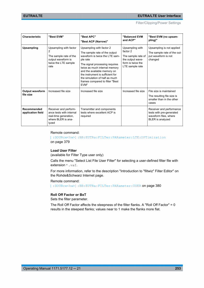
EUTRA/LTE User InterfaceEUTRA/LTE
253Operating Manual 1171.5177.12 ─ 21
Characteristic "Best EVM" "Best APC"
"Best ACP (Narrow)"
"Balanced EVMand ACP"
"Best EVM (no upsam-pling)"
Upsampling Upsampling with factor2
The sample rate of theoutput waveform istwice the LTE samplerate
Upsampling with factor 2
The sample rate of the outputwaveform is twice the LTE sam-ple rate
The signal processing requirestwice as much internal memoryand the available memory onthe instrument is sufficient forthe simulation of half as muchframes compared to filter "BestEVM"
Upsampling withfactor 2
The sample rate ofthe output wave-form is twice theLTE sample rate
Upsampling is not applied
The sample rate of the out-put waveform is notchanged
Output waveformfile size
Increased file size Increased file size Increased file size File size is maintained
The resulting file size issmaller than in the othercases
Recommendedapplication field
Receiver and perform-ance tests with internalreal-time generation,where BLER is ana-lyzed
Transmitter and componentstests where excellent ACP isrequired
Receiver and performancetests with pre-generatedwaveform files, whereBLER is analyzed
Remote command: [:SOURce<hw>]: BB: EUTRa:FILTer: PARameter: LTE:OPTimization on page 379
Load User Filter(available for Filter Type user only)
Calls the menu "Select List File User Filter" for selecting a user-defined filter file withextension *.vaf.
For more information, refer to the description "Introduction to "filtwiz" Filter Editor" onthe Rohde&Schwarz Internet page.
Remote command: [:SOURce<hw>]: BB:EUTRa:FILTer: PARameter: USER on page 380
Roll Off Factor or BxTSets the filter parameter.
The Roll Off Factor affects the steepness of the filter flanks. A "Roll Off Factor" = 0results in the steepest flanks; values near to 1 make the flanks more flat.
Filter/Clipping/Power Settings
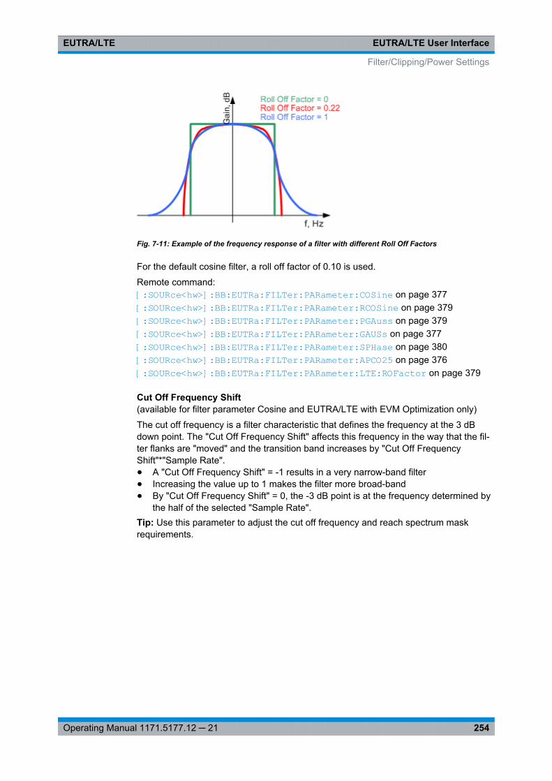
EUTRA/LTE User InterfaceEUTRA/LTE
254Operating Manual 1171.5177.12 ─ 21
Fig. 7-11: Example of the frequency response of a filter with different Roll Off Factors
For the default cosine filter, a roll off factor of 0.10 is used.
Remote command: [:SOURce<hw>]: BB:EUTRa: FILTer: PARameter: COSine on page 377[:SOURce<hw>]: BB:EUTRa: FILTer: PARameter: RCOSine on page 379[:SOURce<hw>]: BB:EUTRa: FILTer: PARameter: PGAuss on page 379[:SOURce<hw>]: BB:EUTRa: FILTer: PARameter: GAUSs on page 377[:SOURce<hw>]: BB:EUTRa: FILTer: PARameter: SPHase on page 380[:SOURce<hw>]: BB:EUTRa: FILTer: PARameter: APCO25 on page 376[:SOURce<hw>]: BB:EUTRa: FILTer: PARameter: LTE: ROFactor on page 379
Cut Off Frequency Shift(available for filter parameter Cosine and EUTRA/LTE with EVM Optimization only)
The cut off frequency is a filter characteristic that defines the frequency at the 3 dBdown point. The "Cut Off Frequency Shift" affects this frequency in the way that the fil-ter flanks are "moved" and the transition band increases by "Cut Off FrequencyShift"*"Sample Rate".● A "Cut Off Frequency Shift" = -1 results in a very narrow-band filter● Increasing the value up to 1 makes the filter more broad-band● By "Cut Off Frequency Shift" = 0, the -3 dB point is at the frequency determined by
the half of the selected "Sample Rate".Tip: Use this parameter to adjust the cut off frequency and reach spectrum maskrequirements.
Filter/Clipping/Power Settings
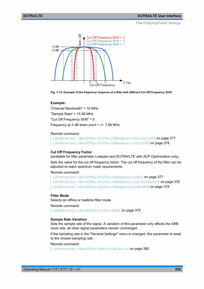
EUTRA/LTE User InterfaceEUTRA/LTE
255Operating Manual 1171.5177.12 ─ 21
Fig. 7-12: Example of the frequency response of a filter with different Cut Off Frequency Shift
Example: "Channel Bandwidth" = 10 MHz"Sample Rate" = 15.36 MHz"Cut Off Frequency Shift" = 0Frequency at 3 dB down point = +/- 7.68 MHz
Remote command: [:SOURce<hw>]: BB: EUTRa:FILTer: PARameter: COSine: COFS on page 377[:SOURce<hw>]: BB: EUTRa:FILTer: PARameter: LTE:COFS on page 378
Cut Off Frequency Factor(available for filter parameter Lowpass and EUTRA/LTE with ACP Optimization only)
Sets the value for the cut off frequency factor. The cut off frequency of the filter can beadjusted to reach spectrum mask requirements.
Remote command: [: SOURce<hw>]: BB:EUTRa: FILTer:PARameter: LPASs on page 377[: SOURce<hw>]: BB:EUTRa: FILTer:PARameter: LTE: COFFactor on page 378[: SOURce<hw>]: BB:EUTRa: FILTer:PARameter: LPASSEVM on page 378
Filter ModeSelects an offline or realtime filter mode.
Remote command: [:SOURce<hw>]: BB: EUTRa:FILTer: MODE on page 375
Sample Rate VariationSets the sample rate of the signal. A variation of this parameter only affects the ARBclock rate; all other signal parameters remain unchanged.
If the sampling rate in the "General Settings" menu is changed, this parameter is resetto the chosen sampling rate.
Remote command: [:SOURce<hw>]: BB: EUTRa:SRATe: VARiation on page 380
Filter/Clipping/Power Settings
EUTRA/LTE User InterfaceEUTRA/LTE
256Operating Manual 1171.5177.12 ─ 21
Impulse Length(For WinIQSIM2 only)
Displays the number of filter tabs. If the check box is activated, the most sensibleparameter values are selected. The value depends on the coherence check. If thecheck box is deactivated, the values can be changed manually.
Remote command: [: SOURce<hw>]: BB:EUTRa: FILTer:ILENgth: AUTO on page 375[: SOURce<hw>]: BB:EUTRa: FILTer:ILENgth on page 375
Oversampling(For WinIQSIM2 only)
Determines the upsampling factor. If the check box is activated, the most sensibleparameter values are selected. The value depends on the coherence check. If thecheck box is deactivated, the values can be changed manually.
Remote command: [: SOURce<hw>]: BB:EUTRa: FILTer:OSAMpling: AUTO on page 376[: SOURce<hw>]: BB:EUTRa: FILTer:OSAMpling on page 376
7.20.3 Clipping Settings
Provided are the following settings:
Clipping StateSwitches baseband clipping on and off.
Baseband clipping is a very simple and effective way of reducing the crest factor of thesignal. Since clipping is done prior to filtering, the procedure does not influence thespectrum. The EVM however increases.
Remote command: [: SOURce<hw>]: BB:EUTRa: CLIPping:STATe on page 382
Clipping LevelSets the limit for clipping.
This value indicates at what point the signal is clipped. It is specified as a percentage,relative to the highest level. 100% indicates that clipping does not take place.
Remote command: [: SOURce<hw>]: BB:EUTRa: CLIPping:LEVel on page 381
Clipping ModeSelects the clipping method. A graphic illustration of the way in which these two meth-ods work is given in the dialog.
● "Vector | i + q |"The limit is related to the amplitude | i + q |. The I and Q components are mappedtogether, the angle is retained.
● "Scalar | i | + | q |"
Filter/Clipping/Power Settings
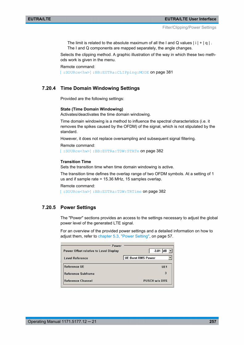
EUTRA/LTE User InterfaceEUTRA/LTE
257Operating Manual 1171.5177.12 ─ 21
The limit is related to the absolute maximum of all the I and Q values | i | + | q | .The I and Q components are mapped separately, the angle changes.
Selects the clipping method. A graphic illustration of the way in which these two meth-ods work is given in the menu.
Remote command: [:SOURce<hw>]: BB:EUTRa: CLIPping: MODE on page 381
7.20.4 Time Domain Windowing Settings
Provided are the following settings:
State (Time Domain Windowing)Activates/deactivates the time domain windowing.
Time domain windowing is a method to influence the spectral characteristics (i.e. itremoves the spikes caused by the OFDM) of the signal, which is not stipulated by thestandard.
However, it does not replace oversampling and subsequent signal filtering.
Remote command: [:SOURce<hw>]: BB: EUTRa:TDW: STATe on page 382
Transition TimeSets the transition time when time domain windowing is active.
The transition time defines the overlap range of two OFDM symbols. At a setting of 1us and if sample rate = 15.36 MHz, 15 samples overlap.
Remote command: [:SOURce<hw>]: BB:EUTRa: TDW:TRTime on page 382
7.20.5 Power Settings
The "Power" sections provides an access to the settings necessary to adjust the globalpower level of the generated LTE signal.
For an overview of the provided power settings and a detailed information on how toadjust them, refer to chapter 5.3, "Power Setting", on page 57.
Filter/Clipping/Power Settings
EUTRA/LTE User InterfaceEUTRA/LTE
258Operating Manual 1171.5177.12 ─ 21
Power Offset Relative to Level DisplaySets the power offset of the according baseband relative to the RMS level displayed inthe instrument’s global Level display in the header of the instrument.
Remote command: [:SOURce<hw>]: BB:EUTRa: POWC:ORTLevel on page 383
Power ReferenceDefines the reference the "Level" display in the status bar is referring to.
"Frame RMSPower"
The displayed RMS and PEP are measured during the whole frame.All frames are considered, not only the first one.
"DL Part ofFrame RMSPower"
The displayed RMS and PEP are measured during the DL part of theframe (all DL subframes and the DwPTS).All frames are considered, not only the first one.
"UL Part ofFrame RMSPower"
The displayed RMS and PEP are measured during the UL part of theframe (all UL subframes and the UpPTS).All frames are considered, not only the first one.
"UE BurstRMS Power"
The displayed RMS and PEP are measured during a single subframeof a certain UE. One of the following channels is used:● PUSCH (without DRS)● PUCCH (without DRS)● PUCCH and PUSCH (both without DRS)● PRACH or● SRS.The subframe, channel and reference used are displayed by meansof the parameters Reference Subframe, Reference Channel and Ref-erence UE.
The instrument selects a suitable reference automatically accordingthe following algorithm:● The first active UE is used● The data part of the first PUSCH/PUCCH is used● In PRACH mode, the first PRACH preamble is used● If there is no active subframe, the SRS is used.This power mode is required for setting the AWGN correctly (e.g.according to TS 36.141), in case not every possible subframe is usedby the simulated UE. The actual part of the signal used for determin-ing RMS and PEP are displayed in the graphical interface.
Remote command: [:SOURce<hw>]: BB: EUTRa:POWC: LEVReference on page 383
Reference UE(enabled for Power Reference set to "UL Burst RMS Power")
Displays the UE the measured RMS and PEP is referring to.
Remote command: [:SOURce<hw>]: BB: EUTRa:POWC: RUE? on page 384
Filter/Clipping/Power Settings
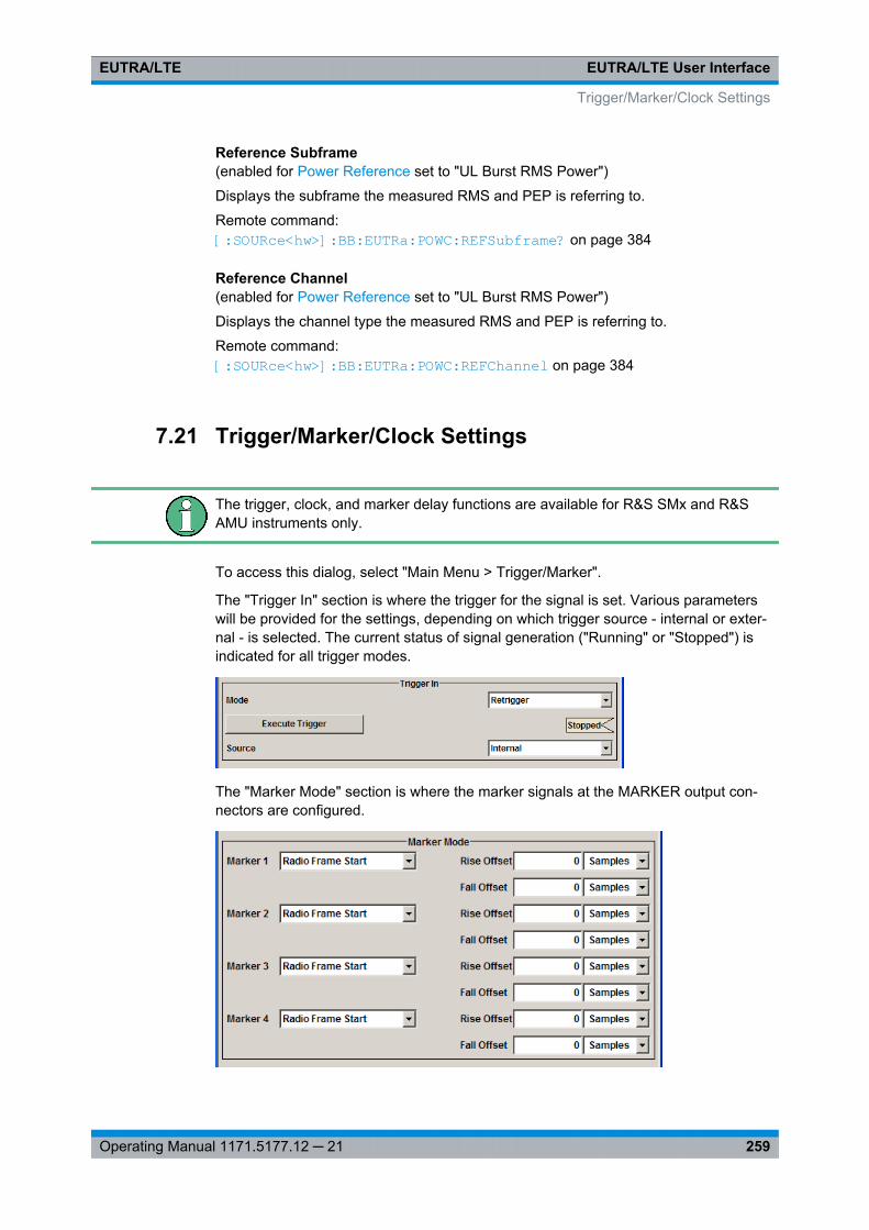
EUTRA/LTE User InterfaceEUTRA/LTE
259Operating Manual 1171.5177.12 ─ 21
Reference Subframe(enabled for Power Reference set to "UL Burst RMS Power")
Displays the subframe the measured RMS and PEP is referring to.
Remote command: [: SOURce<hw>]: BB:EUTRa: POWC:REFSubframe? on page 384
Reference Channel(enabled for Power Reference set to "UL Burst RMS Power")
Displays the channel type the measured RMS and PEP is referring to.
Remote command: [:SOURce<hw>]: BB: EUTRa:POWC: REFChannel on page 384
7.21 Trigger/Marker/Clock Settings
The trigger, clock, and marker delay functions are available for R&S SMx and R&SAMU instruments only.
To access this dialog, select "Main Menu > Trigger/Marker".
The "Trigger In" section is where the trigger for the signal is set. Various parameterswill be provided for the settings, depending on which trigger source - internal or exter-nal - is selected. The current status of signal generation ("Running" or "Stopped") isindicated for all trigger modes.
The "Marker Mode" section is where the marker signals at the MARKER output con-nectors are configured.
Trigger/Marker/Clock Settings
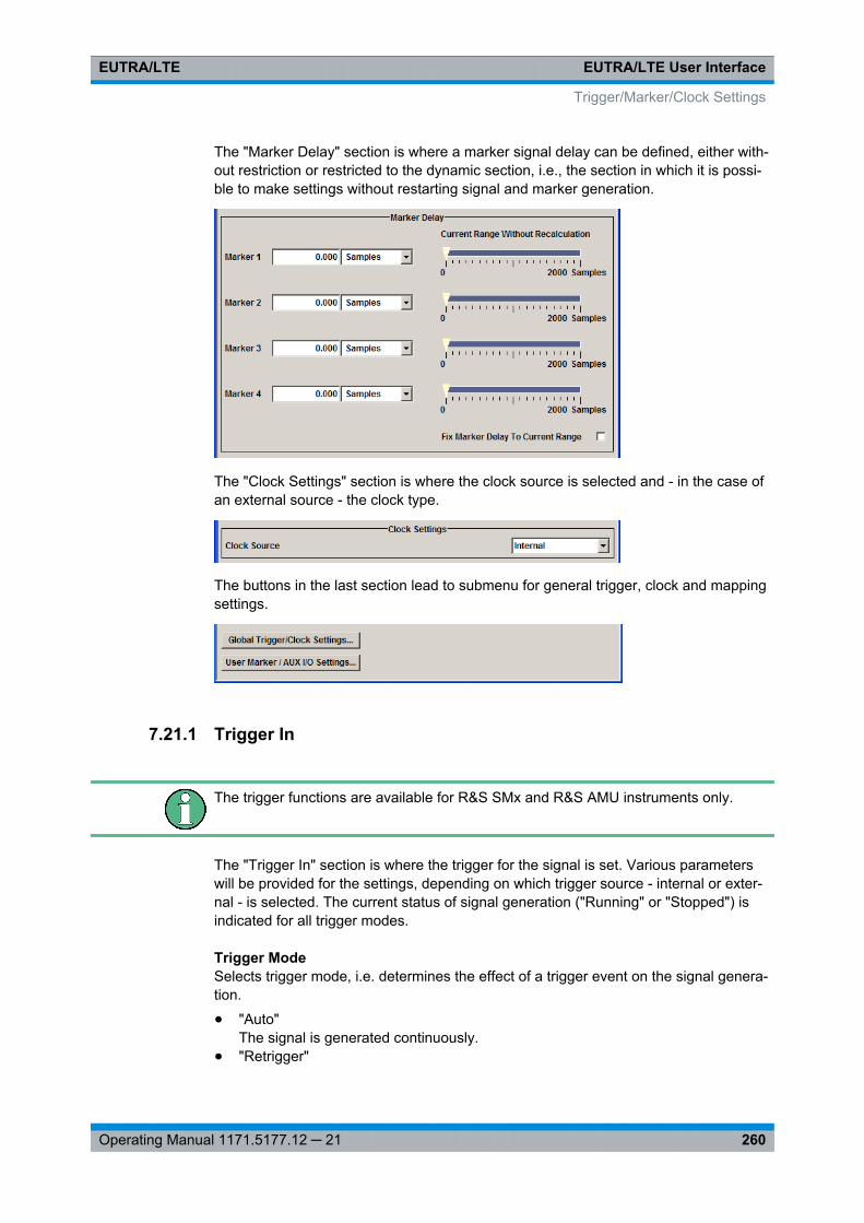
EUTRA/LTE User InterfaceEUTRA/LTE
260Operating Manual 1171.5177.12 ─ 21
The "Marker Delay" section is where a marker signal delay can be defined, either with-out restriction or restricted to the dynamic section, i.e., the section in which it is possi-ble to make settings without restarting signal and marker generation.
The "Clock Settings" section is where the clock source is selected and - in the case ofan external source - the clock type.
The buttons in the last section lead to submenu for general trigger, clock and mappingsettings.
7.21.1 Trigger In
The trigger functions are available for R&S SMx and R&S AMU instruments only.
The "Trigger In" section is where the trigger for the signal is set. Various parameterswill be provided for the settings, depending on which trigger source - internal or exter-nal - is selected. The current status of signal generation ("Running" or "Stopped") isindicated for all trigger modes.
Trigger ModeSelects trigger mode, i.e. determines the effect of a trigger event on the signal genera-tion.
● "Auto"The signal is generated continuously.
● "Retrigger"
Trigger/Marker/Clock Settings
EUTRA/LTE User InterfaceEUTRA/LTE
261Operating Manual 1171.5177.12 ─ 21
The signal is generated continuously. A trigger event (internal or external) causes arestart.
● "Armed_Auto"The signal is generated only when a trigger event occurs. Then the signal is gener-ated continuously.An "Arm" stops the signal generation. A subsequent trigger event (internal with orexternal) causes a restart.
● "Armed_Retrigger"The signal is generated only when a trigger event occurs. Then the signal is gener-ated continuously. Every subsequent trigger event causes a restart.An "Arm" stops signal generation. A subsequent trigger event (internal with orexternal) causes a restart.
● "Single"The signal is generated only when a trigger event occurs. Then the signal is gener-ated once to the length specified at "Signal Duration".Every subsequent trigger event (internal or external) causes a restart.
Use the "Armed_Auto" mode for Base Station Tests if a frame marker from the deviceunder test starts the signal output. Subsequent frame markers will not cause a restartof the signal.
Remote command: [:SOURce<hw>]: BB:EUTRa[: TRIGger]: SEQuence on page 389
Signal Duration UnitDefines the unit for describing the length of the signal sequence to be output in the"Single" trigger mode.
Remote command: [:SOURce<hw>]: BB:EUTRa: TRIGger: SLUNit on page 395
Signal DurationEnters the length of the signal sequence to be output in the "Single" trigger mode.
Use this parameter to deliberately output part of the signal, an exact sequence of thesignal, or a defined number of repetitions of the signal.
Remote command: [:SOURce<hw>]: BB:EUTRa: TRIGger: SLENgth on page 395
Running/StoppedFor enabled modulation, displays the status of signal generation for all trigger modes.
● "Running"The signal is generated; a trigger was (internally or externally) initiated in triggeredmode.
● "Stopped"The signal is not generated and the instrument waits for a trigger event.
Remote command: [:SOURce<hw>]: BB: EUTRa: TRIGger: RMODe? on page 394
Trigger/Marker/Clock Settings
EUTRA/LTE User InterfaceEUTRA/LTE
262Operating Manual 1171.5177.12 ─ 21
ArmStops signal generation. This button appears only with "Running" signal generation inthe "Armed_Auto" and "Armed_Retrigger" trigger modes.
Signal generation can be restarted by a new trigger (internally with "Execute Trigger"or externally).
Remote command: [:SOURce<hw>]: BB: EUTRa:TRIGger: ARM:EXECute on page 390
Execute TriggerExecutes trigger manually. A manual trigger can be executed only when an internaltrigger source and a trigger mode other than "Auto" have been selected.
Remote command: [:SOURce<hw>]: BB: EUTRa:TRIGger: EXECute on page 391
Trigger SourceSelects trigger source. This setting is effective when a trigger mode other than "Auto"has been selected.
● "Internal"The trigger event is executed by "Execute Trigger".
● "Internal (Baseband A/B)"(two-path instruments)The trigger event is the trigger signal from the second path
● "External (Trigger 1/2)"The trigger event is the active edge of an external trigger signal, supplied at theTRIGGER 1/2 connector.Use the "Global Trigger/Clock Settings" dialog to define the polarity, the triggerthreshold and the input impedance of the trigger signal.
Remote command: [:SOURce<hw>]: BB:EUTRa:TRIGger: SOURce on page 396
Sync. Output to External Trigger(enabled for "Trigger Source" External)
Enables/disables output of the signal synchronous to the external trigger event.
For R&S SMBV instruments:
For or two or more R&S SMBVs configured to work in a master-slave mode for syn-chronous signal generation, configure this parameter depending on the provided sys-tem trigger event and the properties of the output signal. See the table below for anoverview of the required settings.
Trigger/Marker/Clock Settings
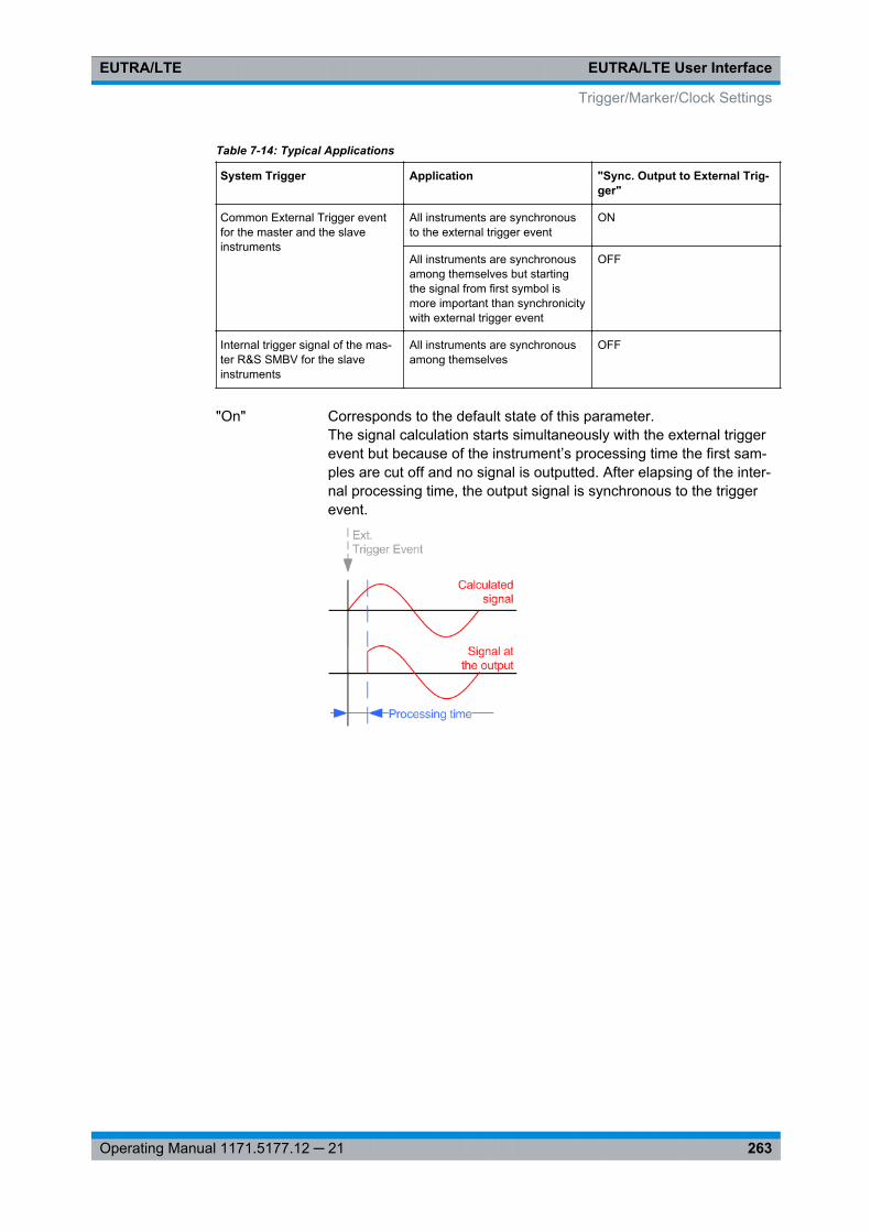
EUTRA/LTE User InterfaceEUTRA/LTE
263Operating Manual 1171.5177.12 ─ 21
Table 7-14: Typical Applications
System Trigger Application "Sync. Output to External Trig-ger"
Common External Trigger eventfor the master and the slaveinstruments
All instruments are synchronousto the external trigger event
ON
All instruments are synchronousamong themselves but startingthe signal from first symbol ismore important than synchronicitywith external trigger event
OFF
Internal trigger signal of the mas-ter R&S SMBV for the slaveinstruments
All instruments are synchronousamong themselves
OFF
"On" Corresponds to the default state of this parameter.The signal calculation starts simultaneously with the external triggerevent but because of the instrument’s processing time the first sam-ples are cut off and no signal is outputted. After elapsing of the inter-nal processing time, the output signal is synchronous to the triggerevent.
Trigger/Marker/Clock Settings
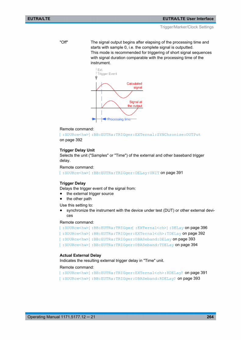
EUTRA/LTE User InterfaceEUTRA/LTE
264Operating Manual 1171.5177.12 ─ 21
"Off" The signal output begins after elapsing of the processing time andstarts with sample 0, i.e. the complete signal is outputted.This mode is recommended for triggering of short signal sequenceswith signal duration comparable with the processing time of theinstrument.
Remote command: [:SOURce<hw>]: BB: EUTRa:TRIGger: EXTernal: SYNChronize: OUTPut on page 392
Trigger Delay UnitSelects the unit ("Samples" or "Time") of the external and other baseband triggerdelay.
Remote command: [:SOURce<hw>]: BB:EUTRa:TRIGger: DELay: UNIT on page 391
Trigger DelayDelays the trigger event of the signal from:● the external trigger source● the other pathUse this setting to:● synchronize the instrument with the device under test (DUT) or other external devi-
ces
Remote command: [:SOURce<hw>]: BB: EUTRa:TRIGger[: EXTernal<ch>]: DELay on page 396[: SOURce<hw>]: BB: EUTRa:TRIGger: EXTernal<ch>: TDELay on page 392[: SOURce<hw>]: BB: EUTRa:TRIGger: OBASeband: DELay on page 393[: SOURce<hw>]: BB: EUTRa:TRIGger: OBASeband: TDELay on page 394
Actual External DelayIndicates the resulting external trigger delay in "Time" unit.
Remote command: [:SOURce<hw>]: BB:EUTRa: TRIGger: EXTernal<ch>: RDELay? on page 391[:SOURce<hw>]: BB:EUTRa: TRIGger: OBASeband: RDELay? on page 393
Trigger/Marker/Clock Settings
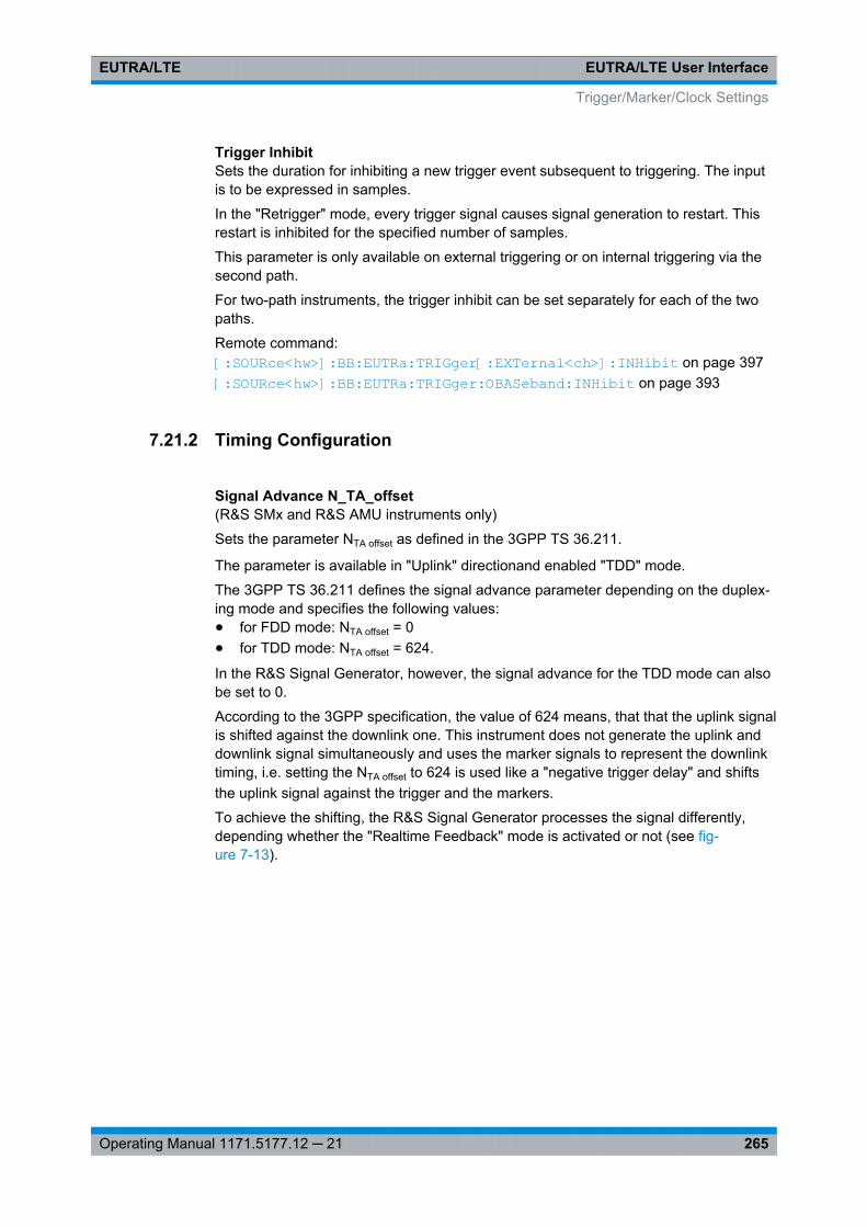
EUTRA/LTE User InterfaceEUTRA/LTE
265Operating Manual 1171.5177.12 ─ 21
Trigger InhibitSets the duration for inhibiting a new trigger event subsequent to triggering. The inputis to be expressed in samples.
In the "Retrigger" mode, every trigger signal causes signal generation to restart. Thisrestart is inhibited for the specified number of samples.
This parameter is only available on external triggering or on internal triggering via thesecond path.
For two-path instruments, the trigger inhibit can be set separately for each of the twopaths.
Remote command: [:SOURce<hw>]: BB: EUTRa:TRIGger[: EXTernal<ch>]: INHibit on page 397[:SOURce<hw>]: BB: EUTRa:TRIGger: OBASeband: INHibit on page 393
7.21.2 Timing Configuration
Signal Advance N_TA_offset(R&S SMx and R&S AMU instruments only)
Sets the parameter NTA offset as defined in the 3GPP TS 36.211.
The parameter is available in "Uplink" directionand enabled "TDD" mode.
The 3GPP TS 36.211 defines the signal advance parameter depending on the duplex-ing mode and specifies the following values:● for FDD mode: NTA offset = 0● for TDD mode: NTA offset = 624.
In the R&S Signal Generator, however, the signal advance for the TDD mode can alsobe set to 0.
According to the 3GPP specification, the value of 624 means, that that the uplink signalis shifted against the downlink one. This instrument does not generate the uplink anddownlink signal simultaneously and uses the marker signals to represent the downlinktiming, i.e. setting the NTA offset to 624 is used like a "negative trigger delay" and shiftsthe uplink signal against the trigger and the markers.
To achieve the shifting, the R&S Signal Generator processes the signal differently,depending whether the "Realtime Feedback" mode is activated or not (see fig-ure 7-13).
Trigger/Marker/Clock Settings
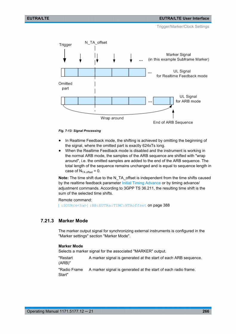
EUTRA/LTE User InterfaceEUTRA/LTE
266Operating Manual 1171.5177.12 ─ 21
Fig. 7-13: Signal Processing
● In Realtime Feedback mode, the shifting is achieved by omitting the beginning ofthe signal, where the omitted part is exactly 624xTs long.
● When the Realtime Feedback mode is disabled and the instrument is working inthe normal ARB mode, the samples of the ARB sequence are shifted with "wraparound", i.e. the omitted samples are added to the end of the ARB sequence. Thetotal length of the sequence remains unchanged and is equal to sequence length incase of NTA offset = 0.
Note: The time shift due to the N_TA_offset is independent from the time shifts causedby the realtime feedback parameter Initial Timing Advance or by timing advance/adjustment commands. According to 3GPP TS 36.211, the resulting time shift is thesum of the selected time shifts.
Remote command: [: SOURce<hw>]: BB:EUTRa: TIMC:NTAoffset on page 388
7.21.3 Marker Mode
The marker output signal for synchronizing external instruments is configured in the"Marker settings" section "Marker Mode".
Marker ModeSelects a marker signal for the associated "MARKER" output.
"Restart(ARB)"
A marker signal is generated at the start of each ARB sequence.
"Radio FrameStart"
A marker signal is generated at the start of each radio frame.
Trigger/Marker/Clock Settings
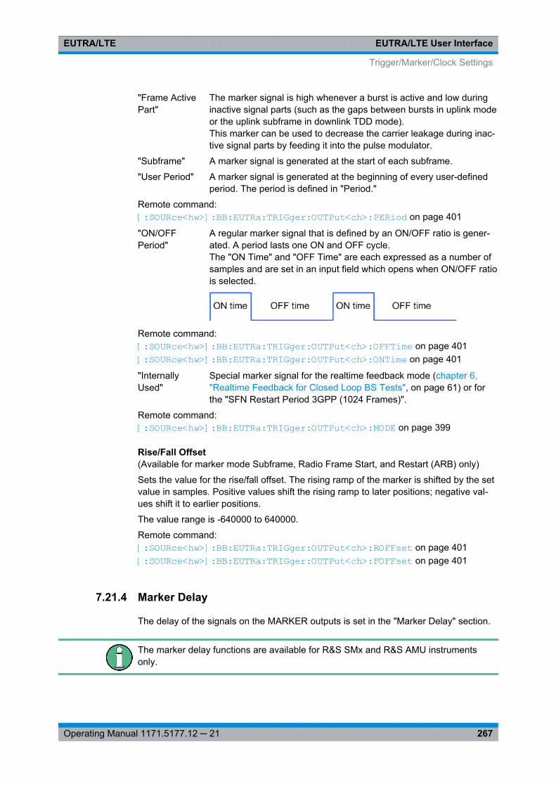
EUTRA/LTE User InterfaceEUTRA/LTE
267Operating Manual 1171.5177.12 ─ 21
"Frame ActivePart"
The marker signal is high whenever a burst is active and low duringinactive signal parts (such as the gaps between bursts in uplink modeor the uplink subframe in downlink TDD mode).This marker can be used to decrease the carrier leakage during inac-tive signal parts by feeding it into the pulse modulator.
"Subframe" A marker signal is generated at the start of each subframe.
"User Period" A marker signal is generated at the beginning of every user-definedperiod. The period is defined in "Period."
Remote command: [:SOURce<hw>]: BB: EUTRa:TRIGger: OUTPut<ch>: PERiod on page 401
"ON/OFFPeriod"
A regular marker signal that is defined by an ON/OFF ratio is gener-ated. A period lasts one ON and OFF cycle.The "ON Time" and "OFF Time" are each expressed as a number ofsamples and are set in an input field which opens when ON/OFF ratiois selected.
Remote command: [:SOURce<hw>]: BB: EUTRa:TRIGger: OUTPut<ch>: OFFTime on page 401[:SOURce<hw>]: BB: EUTRa:TRIGger: OUTPut<ch>: ONTime on page 401
"InternallyUsed"
Special marker signal for the realtime feedback mode (chapter 6,"Realtime Feedback for Closed Loop BS Tests", on page 61) or forthe "SFN Restart Period 3GPP (1024 Frames)".
Remote command: [:SOURce<hw>]: BB: EUTRa:TRIGger: OUTPut<ch>: MODE on page 399
Rise/Fall Offset(Available for marker mode Subframe, Radio Frame Start, and Restart (ARB) only)
Sets the value for the rise/fall offset. The rising ramp of the marker is shifted by the setvalue in samples. Positive values shift the rising ramp to later positions; negative val-ues shift it to earlier positions.
The value range is -640000 to 640000.
Remote command: [:SOURce<hw>]: BB:EUTRa:TRIGger: OUTPut<ch>: ROFFset on page 401[:SOURce<hw>]: BB:EUTRa:TRIGger: OUTPut<ch>: FOFFset on page 401
7.21.4 Marker Delay
The delay of the signals on the MARKER outputs is set in the "Marker Delay" section.
The marker delay functions are available for R&S SMx and R&S AMU instrumentsonly.
Trigger/Marker/Clock Settings

EUTRA/LTE User InterfaceEUTRA/LTE
268Operating Manual 1171.5177.12 ─ 21
The R&S SMBV supports only two markers.
Marker x DelayEnters the delay between the marker signal at the marker outputs and the start of theframe or slot.
Note: The R&S SMBV Vector Signal Generator supports only two markers.The input is expressed as a number of symbols/samples. If the setting "Fix markerdelay to dynamic range" is enabled, the setting range is restricted to the dynamicrange. In this range the delay of the marker signals can be set without restarting themarker and signal.
Remote command: [: SOURce<hw>]: BB:EUTRa: TRIGger: OUTPut<ch>: DELay on page 398
Current Range without RecalculationDisplays the dynamic range within which the delay of the marker signals can be setwithout restarting the marker and signal.
The delay can be defined by moving the setting mark.
Remote command: [: SOURce<hw>]: BB:EUTRa: TRIGger:OUTPut<ch>: DELay: MAXimum? on page 398[: SOURce<hw>]: BB:EUTRa: TRIGger:OUTPut<ch>: DELay: MINimum? on page 399
Fix marker delay to current rangeRestricts the marker delay setting range to the dynamic range. In this range the delaycan be set without restarting the marker and signal.
Remote command: [:SOURce<hw>]: BB: EUTRa:TRIGger: OUTPut: DELay:FIXed on page 397
7.21.5 Clock Settings
The "Clock Settings" are used to set the clock source and a delay if required.
The clock functions are available for R&S SMx and R&S AMU instruments only.
Sync. Mode(for R&S SMBV only)
Selects the synchronization mode.
This parameter is used to enable generation of very precise synchronous signal of sev-eral connected R&S SMBVs.
Note: If several instruments are connected, the connecting cables from the masterinstrument to the slave one and between each two consecutive slave instruments musthave the same length and type.Avoid unnecessary cable length and branching points.
Trigger/Marker/Clock Settings
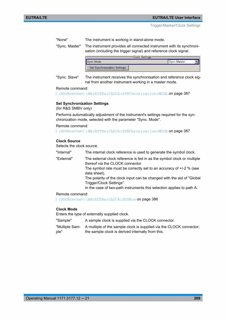
EUTRA/LTE User InterfaceEUTRA/LTE
269Operating Manual 1171.5177.12 ─ 21
"None" The instrument is working in stand-alone mode.
"Sync. Master" The instrument provides all connected instrument with its synchroni-sation (including the trigger signal) and reference clock signal.
"Sync. Slave" The instrument receives the synchronisation and reference clock sig-nal from another instrument working in a master mode.
Remote command: [:SOURce<hw>]: BB: EUTRa:CLOCk: SYNChronization: MODE on page 387
Set Synchronization Settings(for R&S SMBV only)
Performs automatically adjustment of the instrument's settings required for the syn-chronization mode, selected with the parameter "Sync. Mode".
Remote command: [:SOURce<hw>]: BB: EUTRa:CLOCk: SYNChronization: MODE on page 387
Clock SourceSelects the clock source.
"Internal" The internal clock reference is used to generate the symbol clock.
"External" The external clock reference is fed in as the symbol clock or multiplethereof via the CLOCK connector.The symbol rate must be correctly set to an accuracy of +/-2 % (seedata sheet).The polarity of the clock input can be changed with the aid of "GlobalTrigger/Clock Settings".In the case of two-path instruments this selection applies to path A.
Remote command: [:SOURce<hw>]: BB: EUTRa:CLOCk: SOURce on page 386
Clock ModeEnters the type of externally supplied clock.
"Sample" A sample clock is supplied via the CLOCK connector.
"Multiple Sam-ple"
A multiple of the sample clock is supplied via the CLOCK connector;the sample clock is derived internally from this.
Trigger/Marker/Clock Settings
EUTRA/LTE User InterfaceEUTRA/LTE
270Operating Manual 1171.5177.12 ─ 21
"Custom" (not for R&S SMBV)An external custom clock is supplied via the CLOCK connector.The exact frequency of the provided clock has to be defined withparameter "Custom External Clock".
Note: Custom External Clock source in baseband B is only supportedif baseband A is configured with EUTRA/LTE too. Furthermore thesame settings for clock source and clock mode have to be set inbaseband A and B. The user needs to take care of the correct set-tings.
Remote command: [:SOURce<hw>]: BB: EUTRa:CLOCk: MODE on page 385
Clock MultiplierEnters the multiplication factor for clock type "Multiple".
Remote command: [:SOURce<hw>]: BB:EUTRa: CLOCk: MULTiplier on page 386
Custom External ClockSpecifies the parameter for clock type "Custom" in case of external clock source.
Remote command: [: SOURce<hw>]: BB:EUTRa: CLOCk:CUSTom on page 386
Measured External ClockProvided for permanent monitoring of the enabled and externally supplied clock signal.
Remote command: CLOCk:INPut:FREQuency?
7.21.6 Global Settings
The buttons in this section lead to dialogs for general trigger, clock and mapping set-tings.
These settings are available for R&S SMx and R&S AMU instruments only.
Global Trigger/Clock SettingsCalls the "Global Trigger/Clock/Input Settings" dialog.
This dialog is used among other things for setting the trigger threshold, the input impe-dance and the polarity of the clock and trigger inputs.
In the case of two-path instruments, these settings are valid for both paths.
The parameters in this dialog affect all digital modulations and standards, and aredescribed in chapter "Global Trigger/Clock/Input Settings" in the Operating Manual.
User Marker / AUX I/O SettingsCalls the "User Marker AUX I/O Settings" dialog, used to map the connector on therear of the instruments.
See also "User Marker / AUX I/O Settings" in the Operating Manual.
Trigger/Marker/Clock Settings
Test Case WizardEUTRA/LTE
271Operating Manual 1171.5177.12 ─ 21
8 Test Case WizardThe "Test Case Wizard" is supported by R&S SMU, R&S SMATE, R&S SMJ and R&SSMBV.
The "Test Case Wizard" supports tests on base stations in conformance with the 3GPPspecification for Base Station conformance testing. It offers a selection of predefinedsettings according to Test Cases in TS 36.141. For an overview of the test cases cov-ered by the test case wizard, refer to chapter 8.3, "Supported Test Cases",on page 273.
With the "Test Case Wizard", it is possible to create highly complex test scenarios withjust a few keystrokes.
The "Test Case Wizard" has effect on frequency and level settings, link direction, filter,trigger, baseband clock source, marker settings and base station or user equipmentconfiguration. Besides the EUTRA/LTE required settings also interfering signals(AWGN, CW interferer, co-located modulation signals) or fading profiles are set.
The test setups and the hardcopies in this description assume a fully equippedR&S SMU.
8.1 Introduction to Conformance Testing
The main purpose of the conformance testing is to ensure that the base station (BS)and the user equipment (UE) are fulfilling a defined level of minimum performance.
The 3GPP organization defines three groups of conformance testing for the UE: RadioFrequency (RF), Radio Resource Management (RRM) and Signaling. There is onlyone group conformance testing for the BS, the RF conformance tests.
This chapter is intended to give an overview of the 3GPP test specifications dealingwith the conformance tests. Only a brief description is provided.
8.1.1 UE Conformance Testing
The UE conformance tests are not in the scope of this description.
Introduction to Conformance Testing
Test Case WizardEUTRA/LTE
272Operating Manual 1171.5177.12 ─ 21
UE RF FDD/TDD Conformance Test Specifications
The UE RF conformance tests are based on the core specification TS 36.101 and aredefined in the TS 36.521. The following list gives an overview of the related specifica-tions:● TS 36.124 "ElectroMagnetic Compatibility (EMC) requirements for mobile terminals
and ancillary equipment"● TS 36.521-1 "User Equipment (UE) conformance specification; Radio transmission
and reception; Part 1: Conformance testing"Overview of the test cases:– Subclause 6: UE RF transmitter test cases
Transmit power, Output power dynamics, Transmit signal quality, Output RFspectrum emissions and Transmit intermodulation
– Subclause 7: UE RF receiver test casesDiversity characteristics, Reference sensitivity power level, Maximum inputlevel, Adjacent Channel Selectivity (ACS), In-band blocking, Out-of-band block-ing, Narrow band blocking, Spurious response, Intermodulation characteristics,Spurious emissions
– Subclause 8: UE RF FDD/TDD performance test casesDemodulation of PDSCH (Cell-Specific Reference Symbols), Demodulation ofPDSCH (User-Specific Reference Symbols), Demodulation of PDCCH/PCFICH, Demodulation of PHICH, Demodulation of PBCH
● TS 36.521-2 "User Equipment (UE) conformance specification; Radio transmissionand reception; Part 2: Implementation Conformance Statement (ICS)"
● TS 36.521-3 "User Equipment (UE) conformance specification; Radio transmissionand reception; Part 3: Radio Resource Management (RRM) conformance testing"
UE RRM Conformance Test Specifications
The following specifications deal with UE RRM conformance testing:● TS 36.133 "Requirements for support of radio resource management"● TS 36.521-3 "User Equipment (UE) conformance specification; Part 3: Test suites"
UE Signaling Conformance Test Specifications
The UE signaling conformance tests are defined in the TS 36.523.● TS 36.523-1 "User Equipment (UE) conformance specification; Part 1: Protocol
conformance specification"● TS 36.523-2 "User Equipment (UE) conformance specification; Part 2: Implementa-
tion Conformance Statement (ICS) proforma specification"● TS 36.523-3 "User Equipment (UE) conformance specification; Part 3: Test suites"
Introduction to Conformance Testing
Test Case WizardEUTRA/LTE
273Operating Manual 1171.5177.12 ─ 21
8.1.2 BS Conformance Testing
BS RF FDD/TDD Conformance Test Specifications
The BS RF conformance tests are based on the core specification TS 36.101 and aredefined in the TS 36.141.
● TS 36.113 "Base Station (BS) and repeater ElectroMagnetic Compatibility (EMC)"● TS 36.141 "Base Station (BS) conformance testing"
The BS RF Conformance Tests are described in chapter 8.3, "Supported TestCases", on page 273.
8.1.3 Repeater Conformance Testing
The repeater conformance tests are based on the core specification TS 36.106 anddefined in the TS 36.143 "FDD repeater conformance testing".
8.2 Basic Configuration
The basic equipment layout for preforming test with the aid of "Test Case Wizard" isthe same as for the EUTRA/LTE signal generation. It includes the options:● Baseband Main Module (R&S SMU/SMJ/SMATE-B13)● Baseband Generator (R&S SMx-B10)● Digital Standard EUTRA/LTE (R&S SMx-K55)● Frequency option (R&S SMx-B10x: RF 100kHz - x GHz)
However, some of the tests require further options. The additionally required hardwareand/or software options are listed as a prerequisite in the description of the corre-sponding test case.
Test cases where the signal generator hardware and/or software equipment is not suf-ficient are shown in grey color but are not selectable.RF power and frequency limitations of the hardware equipment restrict the settingranges.
8.3 Supported Test Cases
The BS RF conformance tests defined in the TS 36.141 are divided into three mainparts, the RF transmitter characteristics, the RF receiver characteristics and the RFperformance requirements.
The "Test Case Wizard" supports the test cases listed in the tables below.
Basic Configuration
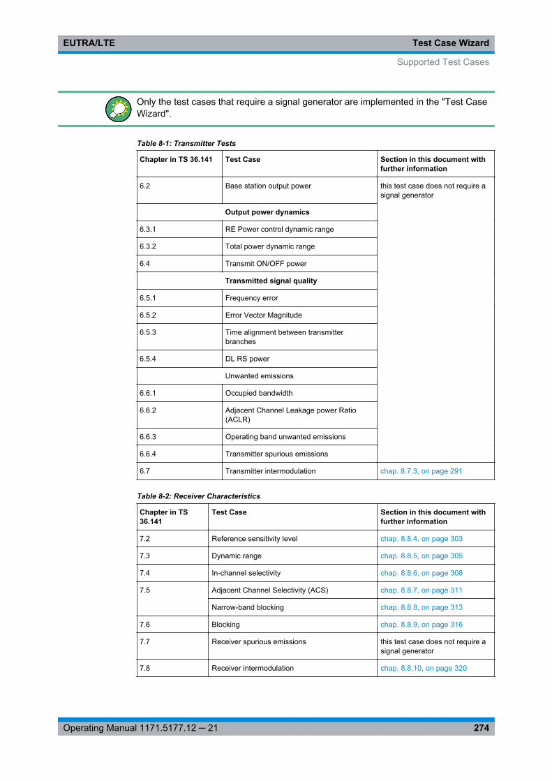
Test Case WizardEUTRA/LTE
274Operating Manual 1171.5177.12 ─ 21
Only the test cases that require a signal generator are implemented in the "Test CaseWizard".
Table 8-1: Transmitter Tests
Chapter in TS 36.141 Test Case Section in this document withfurther information
6.2 Base station output power this test case does not require asignal generator
Output power dynamics
6.3.1 RE Power control dynamic range
6.3.2 Total power dynamic range
6.4 Transmit ON/OFF power
Transmitted signal quality
6.5.1 Frequency error
6.5.2 Error Vector Magnitude
6.5.3 Time alignment between transmitterbranches
6.5.4 DL RS power
Unwanted emissions
6.6.1 Occupied bandwidth
6.6.2 Adjacent Channel Leakage power Ratio(ACLR)
6.6.3 Operating band unwanted emissions
6.6.4 Transmitter spurious emissions
6.7 Transmitter intermodulation chap. 8.7.3, on page 291
Table 8-2: Receiver Characteristics
Chapter in TS36.141
Test Case Section in this document withfurther information
7.2 Reference sensitivity level chap. 8.8.4, on page 303
7.3 Dynamic range chap. 8.8.5, on page 305
7.4 In-channel selectivity chap. 8.8.6, on page 308
7.5 Adjacent Channel Selectivity (ACS) chap. 8.8.7, on page 311
Narrow-band blocking chap. 8.8.8, on page 313
7.6 Blocking chap. 8.8.9, on page 316
7.7 Receiver spurious emissions this test case does not require asignal generator
7.8 Receiver intermodulation chap. 8.8.10, on page 320
Supported Test Cases
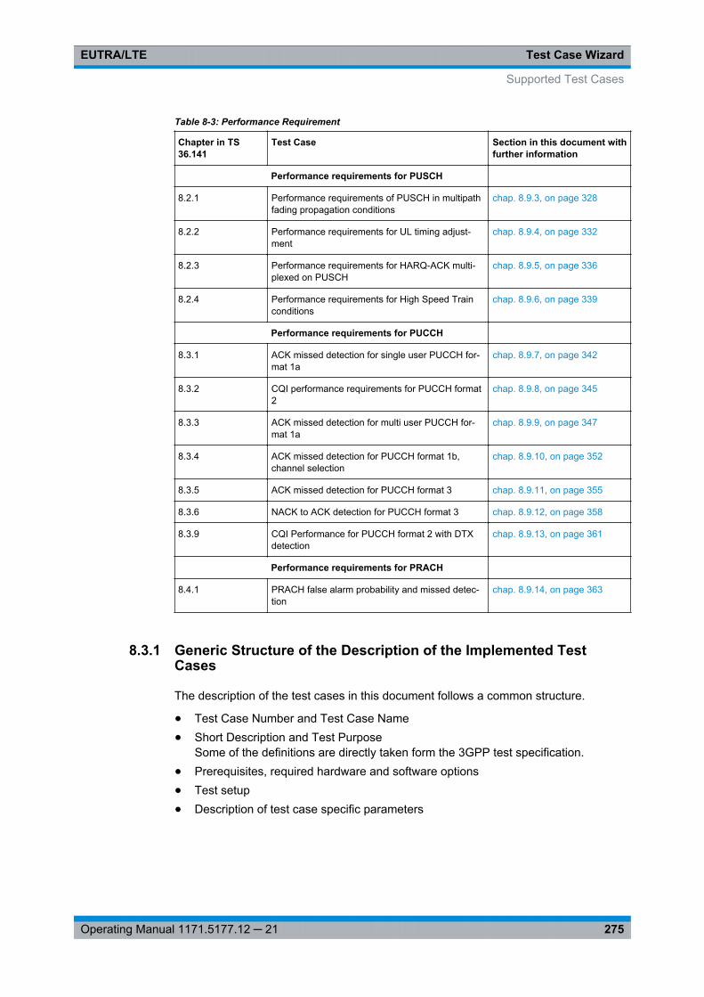
Test Case WizardEUTRA/LTE
275Operating Manual 1171.5177.12 ─ 21
Table 8-3: Performance Requirement
Chapter in TS36.141
Test Case Section in this document withfurther information
Performance requirements for PUSCH
8.2.1 Performance requirements of PUSCH in multipathfading propagation conditions
chap. 8.9.3, on page 328
8.2.2 Performance requirements for UL timing adjust-ment
chap. 8.9.4, on page 332
8.2.3 Performance requirements for HARQ-ACK multi-plexed on PUSCH
chap. 8.9.5, on page 336
8.2.4 Performance requirements for High Speed Trainconditions
chap. 8.9.6, on page 339
Performance requirements for PUCCH
8.3.1 ACK missed detection for single user PUCCH for-mat 1a
chap. 8.9.7, on page 342
8.3.2 CQI performance requirements for PUCCH format2
chap. 8.9.8, on page 345
8.3.3 ACK missed detection for multi user PUCCH for-mat 1a
chap. 8.9.9, on page 347
8.3.4 ACK missed detection for PUCCH format 1b,channel selection
chap. 8.9.10, on page 352
8.3.5 ACK missed detection for PUCCH format 3 chap. 8.9.11, on page 355
8.3.6 NACK to ACK detection for PUCCH format 3 chap. 8.9.12, on page 358
8.3.9 CQI Performance for PUCCH format 2 with DTXdetection
chap. 8.9.13, on page 361
Performance requirements for PRACH
8.4.1 PRACH false alarm probability and missed detec-tion
chap. 8.9.14, on page 363
8.3.1 Generic Structure of the Description of the Implemented TestCases
The description of the test cases in this document follows a common structure.
● Test Case Number and Test Case Name● Short Description and Test Purpose
Some of the definitions are directly taken form the 3GPP test specification.● Prerequisites, required hardware and software options● Test setup● Description of test case specific parameters
Supported Test Cases
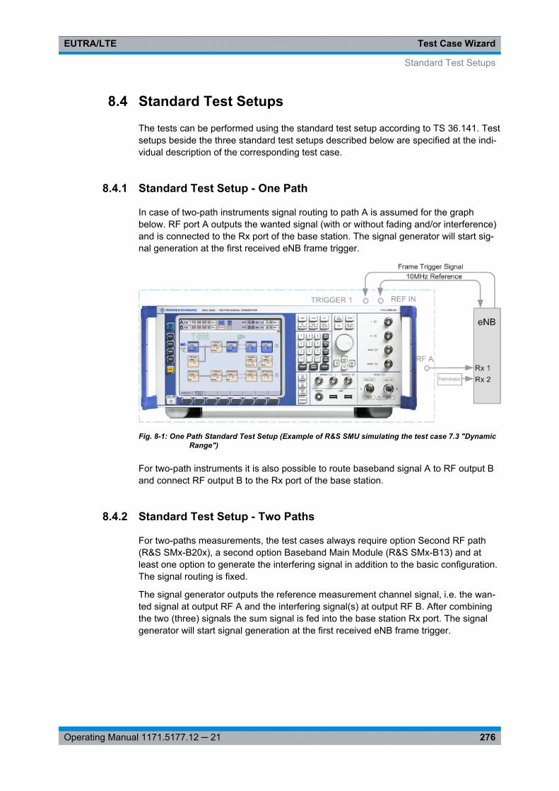
Test Case WizardEUTRA/LTE
276Operating Manual 1171.5177.12 ─ 21
8.4 Standard Test Setups
The tests can be performed using the standard test setup according to TS 36.141. Testsetups beside the three standard test setups described below are specified at the indi-vidual description of the corresponding test case.
8.4.1 Standard Test Setup - One Path
In case of two-path instruments signal routing to path A is assumed for the graphbelow. RF port A outputs the wanted signal (with or without fading and/or interference)and is connected to the Rx port of the base station. The signal generator will start sig-nal generation at the first received eNB frame trigger.
Fig. 8-1: One Path Standard Test Setup (Example of R&S SMU simulating the test case 7.3 "DynamicRange")
For two-path instruments it is also possible to route baseband signal A to RF output Band connect RF output B to the Rx port of the base station.
8.4.2 Standard Test Setup - Two Paths
For two-paths measurements, the test cases always require option Second RF path(R&S SMx-B20x), a second option Baseband Main Module (R&S SMx-B13) and atleast one option to generate the interfering signal in addition to the basic configuration.The signal routing is fixed.
The signal generator outputs the reference measurement channel signal, i.e. the wan-ted signal at output RF A and the interfering signal(s) at output RF B. After combiningthe two (three) signals the sum signal is fed into the base station Rx port. The signalgenerator will start signal generation at the first received eNB frame trigger.
Standard Test Setups
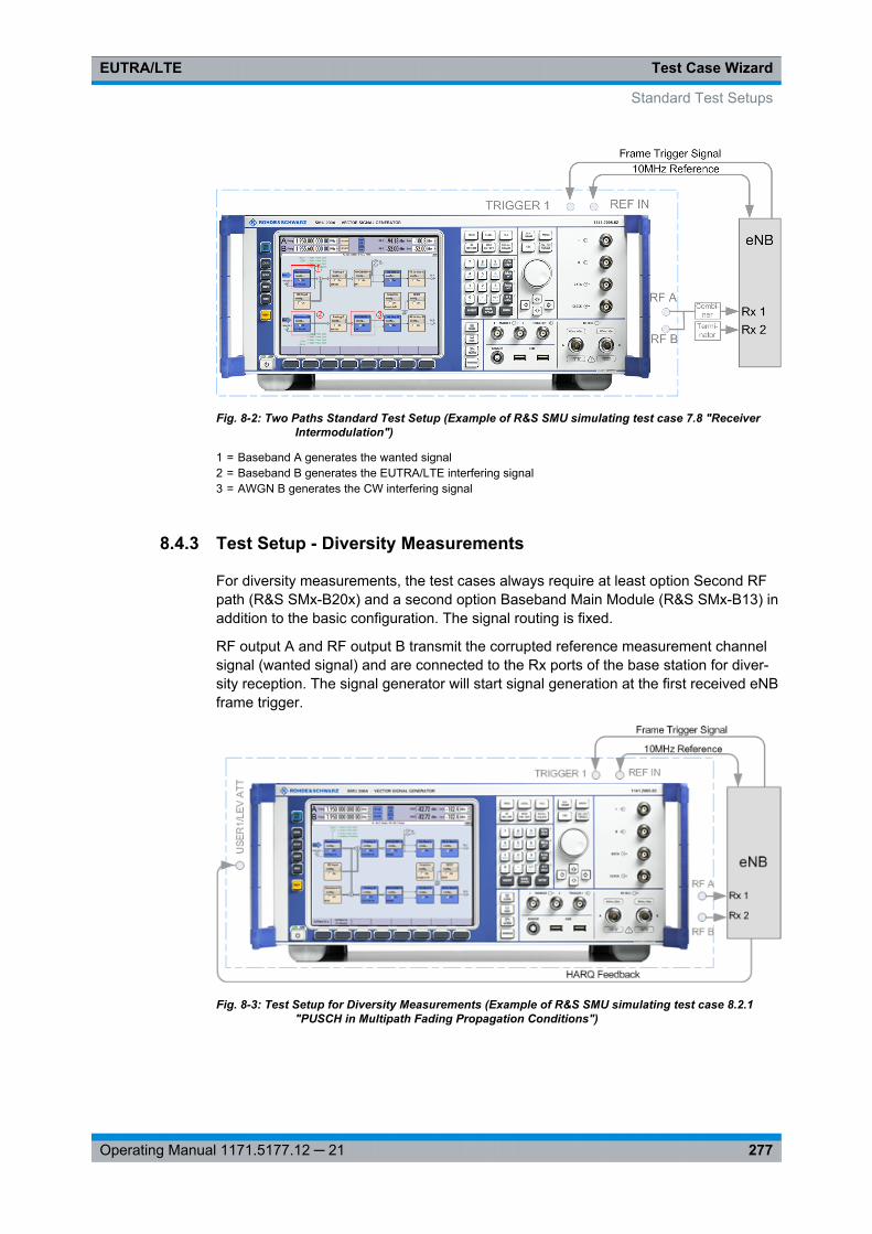
Test Case WizardEUTRA/LTE
277Operating Manual 1171.5177.12 ─ 21
Fig. 8-2: Two Paths Standard Test Setup (Example of R&S SMU simulating test case 7.8 "ReceiverIntermodulation")
1 = Baseband A generates the wanted signal2 = Baseband B generates the EUTRA/LTE interfering signal3 = AWGN B generates the CW interfering signal
8.4.3 Test Setup - Diversity Measurements
For diversity measurements, the test cases always require at least option Second RFpath (R&S SMx-B20x) and a second option Baseband Main Module (R&S SMx-B13) inaddition to the basic configuration. The signal routing is fixed.
RF output A and RF output B transmit the corrupted reference measurement channelsignal (wanted signal) and are connected to the Rx ports of the base station for diver-sity reception. The signal generator will start signal generation at the first received eNBframe trigger.
Fig. 8-3: Test Setup for Diversity Measurements (Example of R&S SMU simulating test case 8.2.1"PUSCH in Multipath Fading Propagation Conditions")
Standard Test Setups
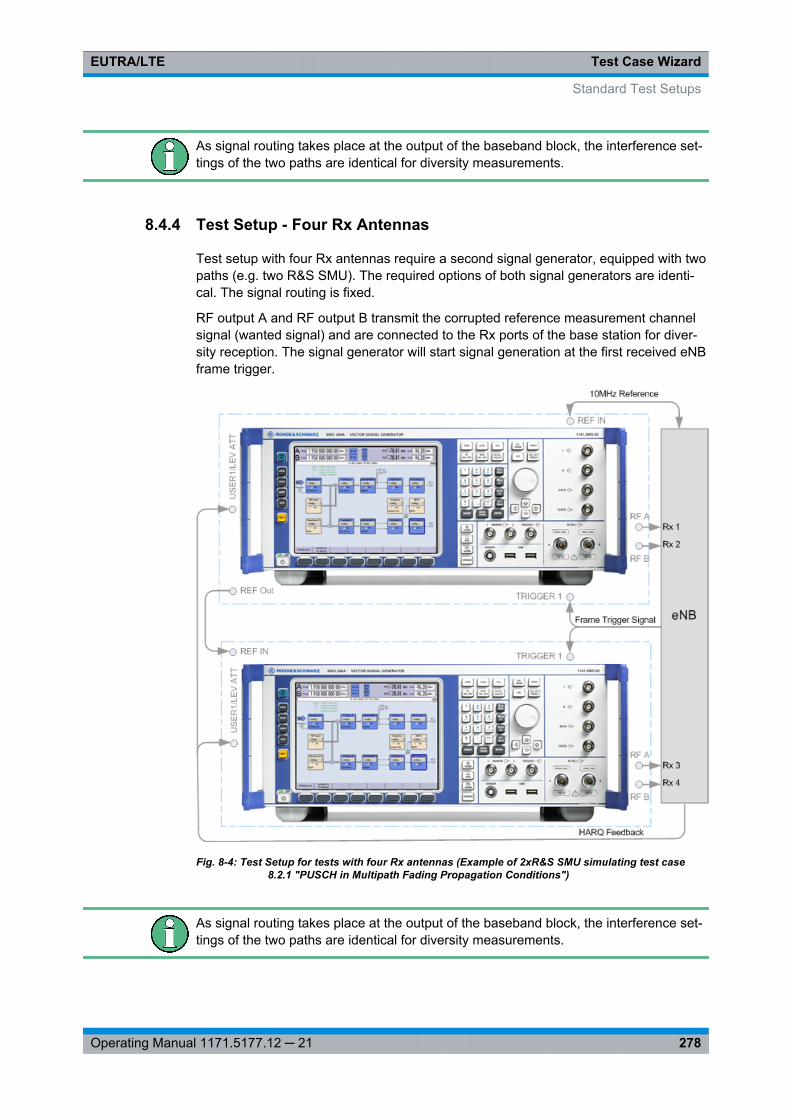
Test Case WizardEUTRA/LTE
278Operating Manual 1171.5177.12 ─ 21
As signal routing takes place at the output of the baseband block, the interference set-tings of the two paths are identical for diversity measurements.
8.4.4 Test Setup - Four Rx Antennas
Test setup with four Rx antennas require a second signal generator, equipped with twopaths (e.g. two R&S SMU). The required options of both signal generators are identi-cal. The signal routing is fixed.
RF output A and RF output B transmit the corrupted reference measurement channelsignal (wanted signal) and are connected to the Rx ports of the base station for diver-sity reception. The signal generator will start signal generation at the first received eNBframe trigger.
Fig. 8-4: Test Setup for tests with four Rx antennas (Example of 2xR&S SMU simulating test case8.2.1 "PUSCH in Multipath Fading Propagation Conditions")
As signal routing takes place at the output of the baseband block, the interference set-tings of the two paths are identical for diversity measurements.
Standard Test Setups
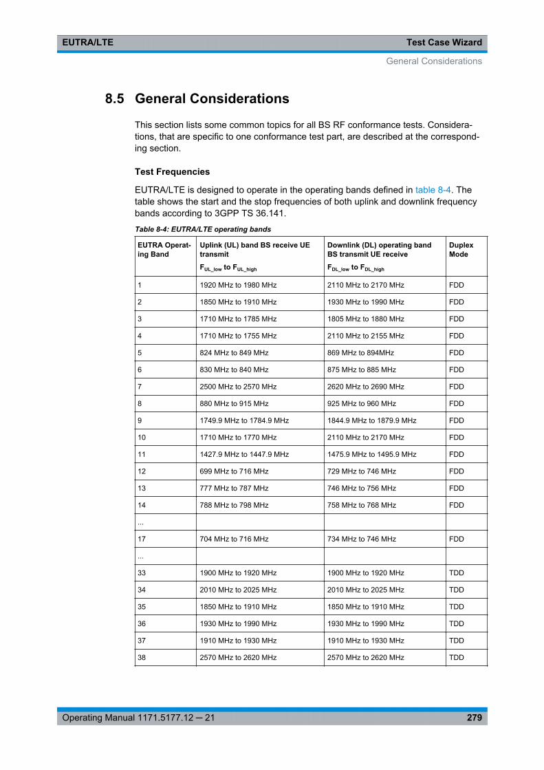
Test Case WizardEUTRA/LTE
279Operating Manual 1171.5177.12 ─ 21
8.5 General Considerations
This section lists some common topics for all BS RF conformance tests. Considera-tions, that are specific to one conformance test part, are described at the correspond-ing section.
Test Frequencies
EUTRA/LTE is designed to operate in the operating bands defined in table 8-4. Thetable shows the start and the stop frequencies of both uplink and downlink frequencybands according to 3GPP TS 36.141.
Table 8-4: EUTRA/LTE operating bands
EUTRA Operat-ing Band
Uplink (UL) band BS receive UEtransmit
FUL_low to FUL_high
Downlink (DL) operating bandBS transmit UE receive
FDL_low to FDL_high
DuplexMode
1 1920 MHz to 1980 MHz 2110 MHz to 2170 MHz FDD
2 1850 MHz to 1910 MHz 1930 MHz to 1990 MHz FDD
3 1710 MHz to 1785 MHz 1805 MHz to 1880 MHz FDD
4 1710 MHz to 1755 MHz 2110 MHz to 2155 MHz FDD
5 824 MHz to 849 MHz 869 MHz to 894MHz FDD
6 830 MHz to 840 MHz 875 MHz to 885 MHz FDD
7 2500 MHz to 2570 MHz 2620 MHz to 2690 MHz FDD
8 880 MHz to 915 MHz 925 MHz to 960 MHz FDD
9 1749.9 MHz to 1784.9 MHz 1844.9 MHz to 1879.9 MHz FDD
10 1710 MHz to 1770 MHz 2110 MHz to 2170 MHz FDD
11 1427.9 MHz to 1447.9 MHz 1475.9 MHz to 1495.9 MHz FDD
12 699 MHz to 716 MHz 729 MHz to 746 MHz FDD
13 777 MHz to 787 MHz 746 MHz to 756 MHz FDD
14 788 MHz to 798 MHz 758 MHz to 768 MHz FDD
...
17 704 MHz to 716 MHz 734 MHz to 746 MHz FDD
...
33 1900 MHz to 1920 MHz 1900 MHz to 1920 MHz TDD
34 2010 MHz to 2025 MHz 2010 MHz to 2025 MHz TDD
35 1850 MHz to 1910 MHz 1850 MHz to 1910 MHz TDD
36 1930 MHz to 1990 MHz 1930 MHz to 1990 MHz TDD
37 1910 MHz to 1930 MHz 1910 MHz to 1930 MHz TDD
38 2570 MHz to 2620 MHz 2570 MHz to 2620 MHz TDD
General Considerations
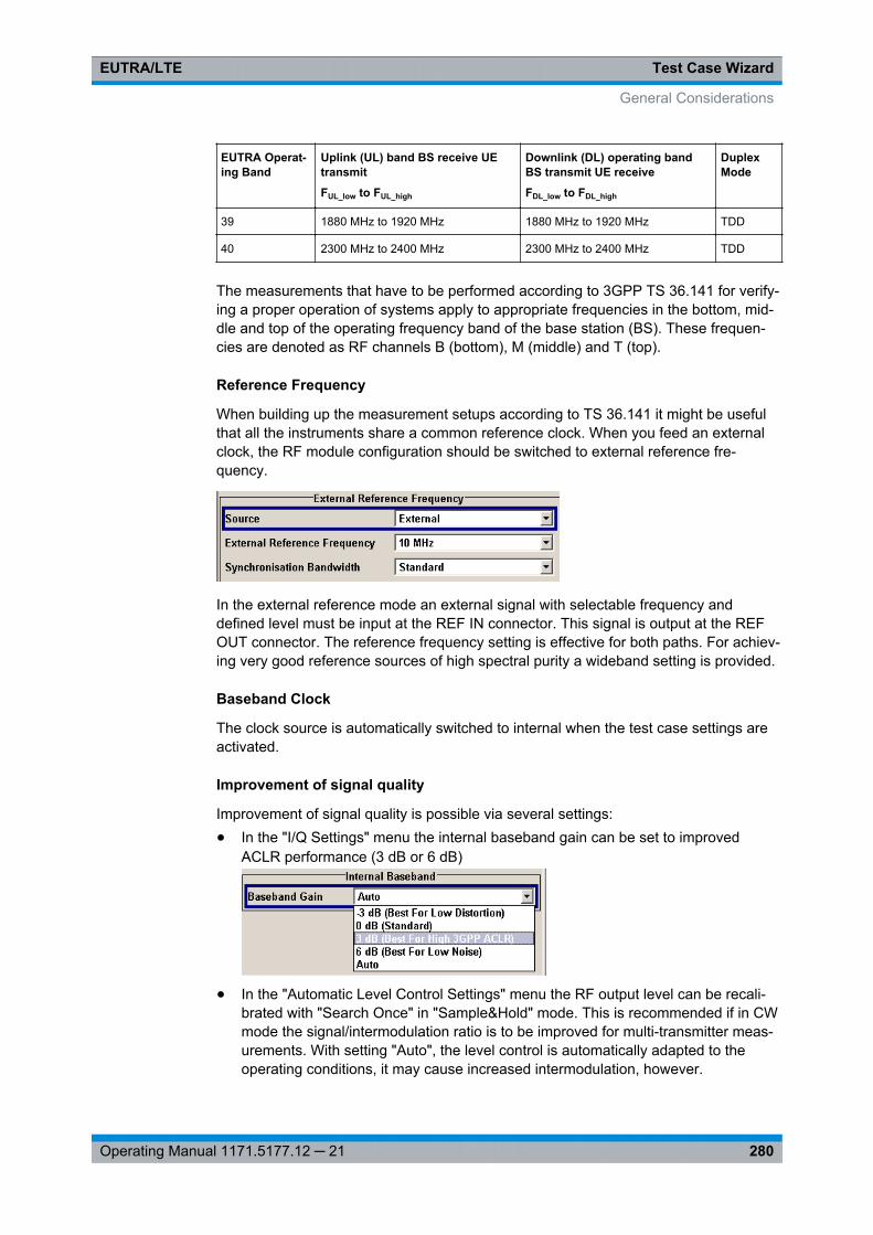
Test Case WizardEUTRA/LTE
280Operating Manual 1171.5177.12 ─ 21
EUTRA Operat-ing Band
Uplink (UL) band BS receive UEtransmit
FUL_low to FUL_high
Downlink (DL) operating bandBS transmit UE receive
FDL_low to FDL_high
DuplexMode
39 1880 MHz to 1920 MHz 1880 MHz to 1920 MHz TDD
40 2300 MHz to 2400 MHz 2300 MHz to 2400 MHz TDD
The measurements that have to be performed according to 3GPP TS 36.141 for verify-ing a proper operation of systems apply to appropriate frequencies in the bottom, mid-dle and top of the operating frequency band of the base station (BS). These frequen-cies are denoted as RF channels B (bottom), M (middle) and T (top).
Reference Frequency
When building up the measurement setups according to TS 36.141 it might be usefulthat all the instruments share a common reference clock. When you feed an externalclock, the RF module configuration should be switched to external reference fre-quency.
In the external reference mode an external signal with selectable frequency anddefined level must be input at the REF IN connector. This signal is output at the REFOUT connector. The reference frequency setting is effective for both paths. For achiev-ing very good reference sources of high spectral purity a wideband setting is provided.
Baseband Clock
The clock source is automatically switched to internal when the test case settings areactivated.
Improvement of signal quality
Improvement of signal quality is possible via several settings:● In the "I/Q Settings" menu the internal baseband gain can be set to improved
ACLR performance (3 dB or 6 dB)
● In the "Automatic Level Control Settings" menu the RF output level can be recali-brated with "Search Once" in "Sample&Hold" mode. This is recommended if in CWmode the signal/intermodulation ratio is to be improved for multi-transmitter meas-urements. With setting "Auto", the level control is automatically adapted to theoperating conditions, it may cause increased intermodulation, however.
General Considerations
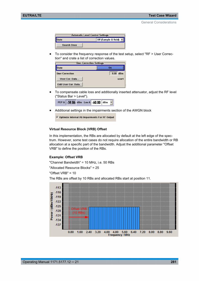
Test Case WizardEUTRA/LTE
281Operating Manual 1171.5177.12 ─ 21
● To consider the frequency response of the test setup, select "RF > User Correc-tion" and crate a list of correction values.
● To compensate cable loss and additionally inserted attenuator, adjust the RF level("Status Bar > Level").
● Additional settings in the impairments section of the AWGN block
Virtual Resource Block (VRB) Offset
In this implementation, the RBs are allocated by default at the left edge of the spec-trum. However, some test cases do not require allocation of the entire bandwidth or RBallocation at a specific part of the bandwidth. Adjust the additional parameter "OffsetVRB" to define the position of the RBs.
Example: Offset VRB"Channel Bandwidth" = 10 MHz, i.e. 50 RBs"Allocated Resource Blocks" = 25"Offset VRB" = 10The RBs are offset by 10 RBs and allocated RBs start at position 11.
General Considerations
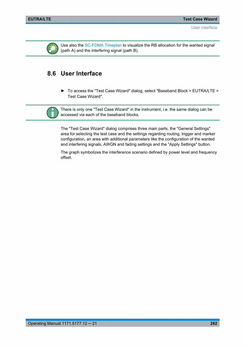
Test Case WizardEUTRA/LTE
282Operating Manual 1171.5177.12 ─ 21
Use also the SC-FDMA Timeplan to visualize the RB allocation for the wanted signal(path A) and the interfering signal (path B).
8.6 User Interface
► To access the "Test Case Wizard" dialog, select "Baseband Block > EUTRA/LTE >Test Case Wizard".
There is only one "Test Case Wizard" in the instrument, i.e. the same dialog can beaccessed via each of the baseband blocks.
The "Test Case Wizard" dialog comprises three main parts, the "General Settings"area for selecting the test case and the settings regarding routing, trigger and markerconfiguration, an area with additional parameters like the configuration of the wantedand interfering signals, AWGN and fading settings and the "Apply Settings" button.
The graph symbolizes the interference scenario defined by power level and frequencyoffset.
User Interface
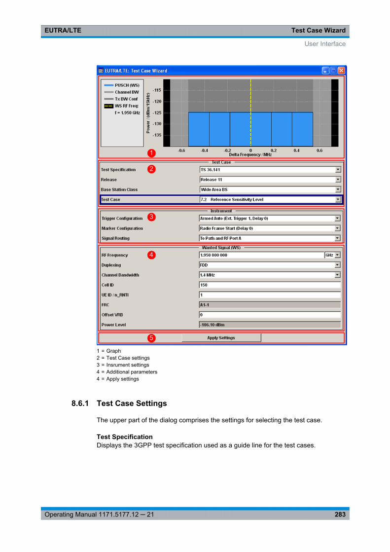
Test Case WizardEUTRA/LTE
283Operating Manual 1171.5177.12 ─ 21
1 = Graph2 = Test Case settings3 = Insrument settings4 = Additional parameters4 = Apply settings
8.6.1 Test Case Settings
The upper part of the dialog comprises the settings for selecting the test case.
Test SpecificationDisplays the 3GPP test specification used as a guide line for the test cases.
User Interface
Test Case WizardEUTRA/LTE
284Operating Manual 1171.5177.12 ─ 21
ReleaseDisplays the 3GPP test specification release version used as a guide line for the testcases.
Remote command: [:SOURce<hw>]: BB:EUTRa: TCW:GS: RELease on page 550
Base Station ClassDetermines whether the test is to be performed for a local area, home area, mediumrange or a wide area base station. The different base station classes are specified fordifferent output power ("Power Level" on page 288).
Remote command: [: SOURce<hw>]: BB:EUTRa: TCW:GS:BSCLass on page 551
Test CaseSelects the test case.
Note: Not all test case are available for all instruments. The enabled test casesdepend on the instrument's hardware (e.g. instrument equipped with one or two paths,etc) and/or the installed SW options (e.g. Fading Simulator, etc.).See chapter 8.3, "Supported Test Cases", on page 273 for an overview of the availabletest cases.
Remote command: [:SOURce<hw>]: BB:EUTRa: TCW:TC on page 558
Number of Rx AntennasFor performance requirement tests, determines the number of the Rx antennas.
Note: Test cases with four antennas require two R&S SMUs.
Remote command: [:SOURce<hw>]: BB:EUTRa: TCW:GS: RXANtennas on page 552
Number of Tx AntennasFor performance requirement tests, determines the number of the Tx antennas.
Note: Test cases with four antennas require two R&S SMUs.
Remote command: [:SOURce<hw>]: BB:EUTRa: TCW:GS: TXANtennas on page 552
8.6.2 Instrument Settings
This section comprises the settings for configuring the general signal generatorsparameters.
Trigger ConfigurationSelects the trigger configuration. The trigger is used to synchronize the signal genera-tor to the other equipment.
User Interface
Test Case WizardEUTRA/LTE
285Operating Manual 1171.5177.12 ─ 21
"Armed Auto(Ext. Trigger 1,Delay 0)"
The trigger settings are customized for the selected test case. Thetrigger setting "Armed Auto" with external trigger source "ExternalTrigger 1" is used; the trigger delay is set equal to zero. Thus, thebase station frame timing is able to synchronize the signal generatorby a periodic trigger.
"Unchanged" The current trigger settings of the signal generator are retainedunchanged.
Remote command: [:SOURce<hw>]: BB: EUTRa:TCW: GS:TRIGgerconfig on page 552
Marker ConfigurationSelects the marker configuration. The marker can be used to synchronize the measur-ing equipment to the signal generator.
"Radio FrameStart (Delay 0)"
The marker settings are customized for the selected test case. "RadioFrame Start" markers are output; the marker delays are set equal tozero.
"Unchanged" The current marker settings of the signal generator are retainedunchanged.
Remote command: [:SOURce<hw>]: BB: EUTRa:TCW: GS:MARKerconfig on page 551
Instrument Setup(two-path instruments only)
Determines whether only one or both paths are used.
Remote command: [: SOURce<hw>]: BB:EUTRa: TCW:GS:INSTsetup on page 551
Signal RoutingSelects the signal routing for baseband A signal which in most test cases representsthe wanted signal.
"To Path andRF Port A"
The baseband signal A is routed to RF output A.
"To Path andRF Port B"
(two-path instruments only)The baseband signal A is routed to RF output B.Tip: Some transmitter tests like test case 7.2 requre separate meas-urements on both Rx port. Use this feature to route the same base-band signal to the second RF output and perform the measurements.
Remote command: [:SOURce<hw>]: BB: EUTRa:TCW: GS:SIGRout on page 552
Antenna SubsetEnabled for test setups with four Rx antennas
Determines the signal of which antenna couple, "Antenna 1 and 2" or "Antenna 3 and4", is generated by the instrument.
Remote command: [:SOURce<hw>]: BB:EUTRa:TCW: GS:ANTSubset on page 550
User Interface
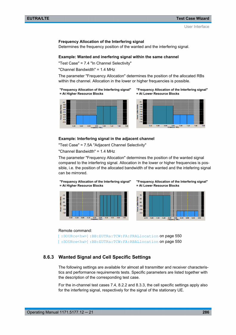
Test Case WizardEUTRA/LTE
286Operating Manual 1171.5177.12 ─ 21
Frequency Allocation of the Interfering signalDetermines the frequency position of the wanted and the interfering signal.
Example: Wanted and inerfering signal within the same channel"Test Case" = 7.4 "In Channel Selectivity""Channel Bandwidth" = 1.4 MHzThe parameter "Frequency Allocation" determines the position of the allocated RBswithin the channel. Allocation in the lower or higher frequencies is possible.
"Frequency Allocation of the Interfering signal"= At Higher Resource Blocks
"Frequency Allocation of the Interfering signal"= At Lower Resource Blocks
Example: Interfering signal in the adjacent channel"Test Case" = 7.5A "Adjacent Channel Selectivity""Channel Bandwidth" = 1.4 MHzThe parameter "Frequency Allocation" determines the position of the wanted signalcompared to the interfering signal. Allocation in the lower or higher frequencies is pos-sible, i.e. the position of the allocated bandwidth of the wanted and the intefering signalcan be mirrored.
"Frequency Allocation of the Interfering signal"= At Higher Resource Blocks
"Frequency Allocation of the Interfering signal"= At Lower Resource Blocks
Remote command: [:SOURce<hw>]: BB: EUTRa:TCW: FA:FRALlocation on page 550[:SOURce<hw>]: BB: EUTRa:TCW: FA:RBALlocation on page 550
8.6.3 Wanted Signal and Cell Specific Settings
The following settings are available for almost all transmitter and receiver characteris-tics and performance requirements tests. Specific parameters are listed together withthe description of the corresponding test case.
For the in-channel test cases 7.4, 8.2.2 and 8.3.3, the cell specific settings apply alsofor the interfering signal, respectively for the signal of the stationary UE.
User Interface
Test Case WizardEUTRA/LTE
287Operating Manual 1171.5177.12 ─ 21
RF FrequencySets the RF frequency of the wanted signal.
Remote command: [:SOURce<hw>]: BB:EUTRa: TCW:WS:RFFRequency on page 563
DuplexingSelects whether TDD or FDD duplexing mode is used (see also "Duplexing"on page 77).
Remote command: [:SOURce<hw>]: BB: EUTRa:TCW: WS:DUPLex on page 561
TDD UL/DL ConfigurationFor TDD mode, selects the UL/DL Configuration number (see also "UL/DL Configura-tion" on page 116).
Remote command: [:SOURce<hw>]: BB:EUTRa:TCW: WS:TDDConfig on page 564
Signal Advance N_TA_offsetSets the parameter NTAoffset (see also "Signal Advance N_TA_offset" on page 265).
Remote command: [:SOURce<hw>]: BB:EUTRa:TCW: WS:NTAOffset on page 561
Channel BandwidthSelects the channel bandwidth (see also chapter 7.13.1, "Physical Settings",on page 194).
Remote command: [:SOURce<hw>]: BB:EUTRa:TCW: WS:CHBW on page 560
Cell IDSets the Cell ID (see alsochapter 7.13.3, "Cell Specific Settings", on page 197 ).
Remote command: [: SOURce<hw>]: BB:EUTRa: TCW:WS:CLID on page 560
Cyclic PrefixSelects normal or extended cyclic prefix.
Remote command: [:SOURce<hw>]: BB: EUTRa: TCW: WS:CYCPrefix on page 560
UE ID/n_RNTISets the UE ID/n_RNTI.
Remote command: [:SOURce<hw>]: BB:EUTRa:TCW: WS:UEID on page 564
User Interface
Test Case WizardEUTRA/LTE
288Operating Manual 1171.5177.12 ─ 21
FRCDisplays the fixed reference channel used. An overview of the FRCs and the cross-ref-erence between the selected Channel Bandwidth and the FRC is given in the individualdescription of the test cases.
Remote command: [: SOURce<hw>]: BB:EUTRa: TCW:WS:FRC on page 561
Offset VRBSets the number of RB the allocated RB(s) are shifted with (see also example "OffsetVRB" on page 281).
Remote command: [:SOURce<hw>]: BB: EUTRa:TCW: WS:OVRB on page 562
Power LevelDisplays the power level, depending on the selected test case.
Remote command: [:SOURce<hw>]: BB: EUTRa:TCW: WS:PLEVel? on page 563
8.6.4 Apply
Button "Apply Settings" triggers a selective preset of the signal generator prior to pre-setting the setting according to the selected test case. Further modification of the gen-erator settings is still possible. Signal generation starts with the first trigger event.
Apply SettingsActivates the current settings of the test case wizard.
Note: The settings of the selected test case becomes active only after selecting "ApplySettings".Initialization of the signal generator with the test case settings is performed by a partialselective reset that includes only the baseband, fading and AWGN module and the RFfrequency and RF level settings. Other settings of the signal generator are not altered.
Before triggering the signal generator the user still can change these other settings.This is particularly useful when compensating for cable loss and additionally insertedattenuators by adjusting the RF power level offset is required.
Signal generation is started at the first trigger received by the generator. The RF outputis not activated /deactivated by the test case wizard. Activate the "RF > State > On" atthe beginning of the measurement.
Note: For safety reasons the RF is not active unless the button "RF ON" has beenselected.Note: The settings in the dialogs "EUTRA/LTE > Trigger/Marker/Clock", in the "GlobalTrigger/Clock Settings" and in the "User Marker / AUX I/O Settings" are not affected bythe selective preset, if the parameter "Trigger/Marker Configuration" is set to"Unchanged".
Remote command: [:SOURce<hw>]: BB:EUTRa:TCW: APPLysettings on page 549
User Interface
Test Case WizardEUTRA/LTE
289Operating Manual 1171.5177.12 ─ 21
8.7 Transmitter Characteristics (TS 36.141, Chapter 6)
The transmitter characteristics comprises the maximum output power, output powerdynamics, transmitted signal quality, unwanted emissions and transmitter intermodula-tions. The "Test Case Wizard" supports the generation of signals in accordance withthe transmitter intermodulations test case. A brief description about the unwantedemission tests is also provided (see chapter 8.7.2, "Introduction to the Unwanted Emis-sions Tests", on page 289).
8.7.1 Prior Considerations
Test Models
For the transmitter characteristic tests EUTRA test models (E-TM) are specified. Foran overview of the test models, see "EUTRA Test Models (E-TM) Downlink"on page 93.
Channels
According to the TS 36.141, the channels to test are located in the bottom (B), middle(M) and the top (T) of the supported frequency range of the base station. See table 8-4for an overview of the supported frequency operating bands.
Filter Settings
The 3GPP EUTRA/LTE specifications do not define a standardized transmit filter nei-ther for the UE nor for the base station. Therefore, when a test case is activated, a filtertype EUTRA/LTE with "Best ACP Optimization" is automatically selected.
Test Setup
Transmitter tests require a separate measuring equipment, e.g. the Vector Signal Ana-lyzer R&S FSV.
8.7.2 Introduction to the Unwanted Emissions Tests
The unwanted emissions from the transmitter are divided into two main groups, theout-of-band (OOB) emissions and the spurious emissions. The out-of-band emissionsare emissions on frequencies close to the frequency of the wanted signal. Spuriousemissions are emissions caused by unwanted transmitter effects, like harmonics, para-sitic emissions, intermodulation products and frequency conversion products.
● ACLRThe Adjacent Channel Leakage power Ratio (ACLR) is defined as the ratiobetween the power transmitted in the channel bandwidth of the wanted signal tothe power of the unwanted emissions transmitted on the adjacent channel.The corresponding receiver requirement is the Adjacent Channel Selectivity (ACS),described in chapter 8.8.7, "Test Case 7.5A: Adjacent Channel Selectivity (ACS)",on page 311.
Transmitter Characteristics (TS 36.141, Chapter 6)
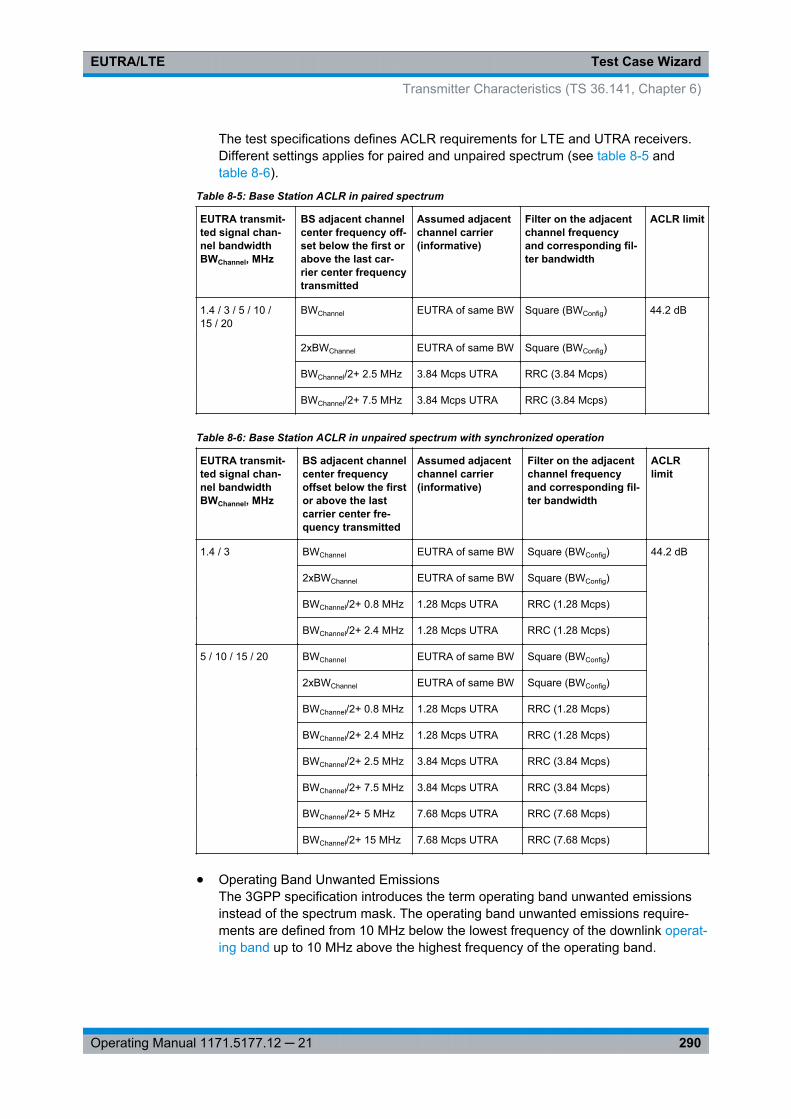
Test Case WizardEUTRA/LTE
290Operating Manual 1171.5177.12 ─ 21
The test specifications defines ACLR requirements for LTE and UTRA receivers.Different settings applies for paired and unpaired spectrum (see table 8-5 andtable 8-6).
Table 8-5: Base Station ACLR in paired spectrum
EUTRA transmit-ted signal chan-nel bandwidthBWChannel, MHz
BS adjacent channelcenter frequency off-set below the first orabove the last car-rier center frequencytransmitted
Assumed adjacentchannel carrier(informative)
Filter on the adjacentchannel frequencyand corresponding fil-ter bandwidth
ACLR limit
1.4 / 3 / 5 / 10 /15 / 20
BWChannel EUTRA of same BW Square (BWConfig) 44.2 dB
2xBWChannel EUTRA of same BW Square (BWConfig)
BWChannel/2+ 2.5 MHz 3.84 Mcps UTRA RRC (3.84 Mcps)
BWChannel/2+ 7.5 MHz 3.84 Mcps UTRA RRC (3.84 Mcps)
Table 8-6: Base Station ACLR in unpaired spectrum with synchronized operation
EUTRA transmit-ted signal chan-nel bandwidthBWChannel, MHz
BS adjacent channelcenter frequencyoffset below the firstor above the lastcarrier center fre-quency transmitted
Assumed adjacentchannel carrier(informative)
Filter on the adjacentchannel frequencyand corresponding fil-ter bandwidth
ACLRlimit
1.4 / 3 BWChannel EUTRA of same BW Square (BWConfig) 44.2 dB
2xBWChannel EUTRA of same BW Square (BWConfig)
BWChannel/2+ 0.8 MHz 1.28 Mcps UTRA RRC (1.28 Mcps)
BWChannel/2+ 2.4 MHz 1.28 Mcps UTRA RRC (1.28 Mcps)
5 / 10 / 15 / 20 BWChannel EUTRA of same BW Square (BWConfig)
2xBWChannel EUTRA of same BW Square (BWConfig)
BWChannel/2+ 0.8 MHz 1.28 Mcps UTRA RRC (1.28 Mcps)
BWChannel/2+ 2.4 MHz 1.28 Mcps UTRA RRC (1.28 Mcps)
BWChannel/2+ 2.5 MHz 3.84 Mcps UTRA RRC (3.84 Mcps)
BWChannel/2+ 7.5 MHz 3.84 Mcps UTRA RRC (3.84 Mcps)
BWChannel/2+ 5 MHz 7.68 Mcps UTRA RRC (7.68 Mcps)
BWChannel/2+ 15 MHz 7.68 Mcps UTRA RRC (7.68 Mcps)
● Operating Band Unwanted EmissionsThe 3GPP specification introduces the term operating band unwanted emissionsinstead of the spectrum mask. The operating band unwanted emissions require-ments are defined from 10 MHz below the lowest frequency of the downlink operat-ing band up to 10 MHz above the highest frequency of the operating band.
Transmitter Characteristics (TS 36.141, Chapter 6)
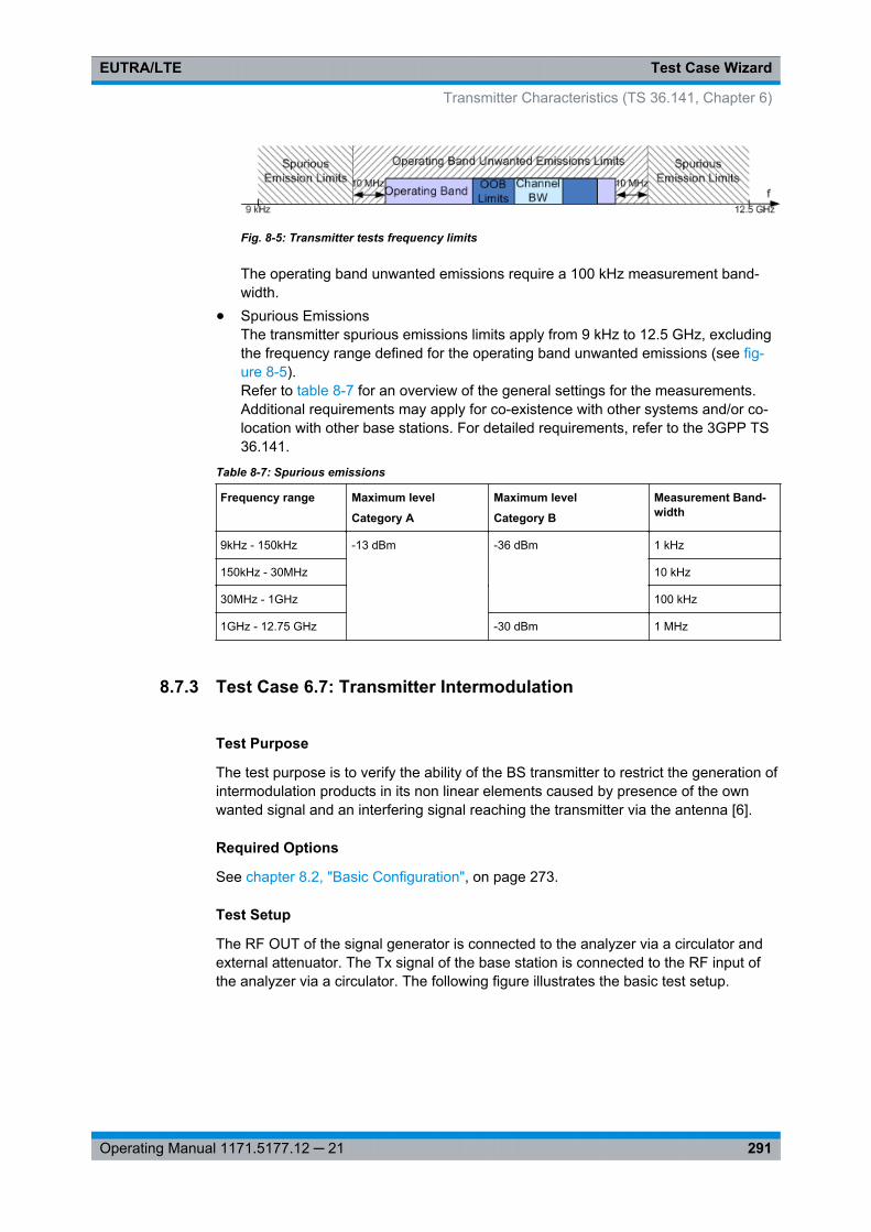
Test Case WizardEUTRA/LTE
291Operating Manual 1171.5177.12 ─ 21
Fig. 8-5: Transmitter tests frequency limits
The operating band unwanted emissions require a 100 kHz measurement band-width.
● Spurious EmissionsThe transmitter spurious emissions limits apply from 9 kHz to 12.5 GHz, excludingthe frequency range defined for the operating band unwanted emissions (see fig-ure 8-5).Refer to table 8-7 for an overview of the general settings for the measurements.Additional requirements may apply for co-existence with other systems and/or co-location with other base stations. For detailed requirements, refer to the 3GPP TS36.141.
Table 8-7: Spurious emissions
Frequency range Maximum level
Category A
Maximum level
Category B
Measurement Band-width
9kHz - 150kHz -13 dBm -36 dBm 1 kHz
150kHz - 30MHz 10 kHz
30MHz - 1GHz 100 kHz
1GHz - 12.75 GHz -30 dBm 1 MHz
8.7.3 Test Case 6.7: Transmitter Intermodulation
Test Purpose
The test purpose is to verify the ability of the BS transmitter to restrict the generation ofintermodulation products in its non linear elements caused by presence of the ownwanted signal and an interfering signal reaching the transmitter via the antenna [6].
Required Options
See chapter 8.2, "Basic Configuration", on page 273.
Test Setup
The RF OUT of the signal generator is connected to the analyzer via a circulator andexternal attenuator. The Tx signal of the base station is connected to the RF input ofthe analyzer via a circulator. The following figure illustrates the basic test setup.
Transmitter Characteristics (TS 36.141, Chapter 6)
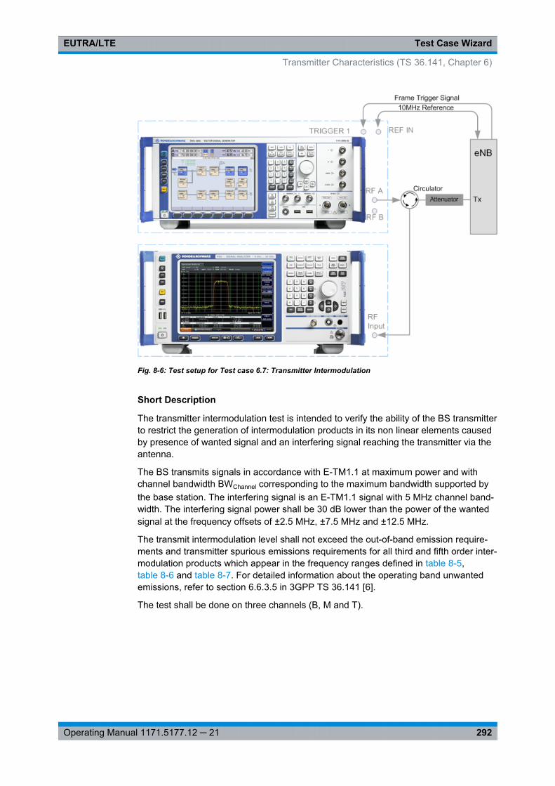
Test Case WizardEUTRA/LTE
292Operating Manual 1171.5177.12 ─ 21
Fig. 8-6: Test setup for Test case 6.7: Transmitter Intermodulation
Short Description
The transmitter intermodulation test is intended to verify the ability of the BS transmitterto restrict the generation of intermodulation products in its non linear elements causedby presence of wanted signal and an interfering signal reaching the transmitter via theantenna.
The BS transmits signals in accordance with E-TM1.1 at maximum power and withchannel bandwidth BWChannel corresponding to the maximum bandwidth supported bythe base station. The interfering signal is an E-TM1.1 signal with 5 MHz channel band-width. The interfering signal power shall be 30 dB lower than the power of the wantedsignal at the frequency offsets of ±2.5 MHz, ±7.5 MHz and ±12.5 MHz.
The transmit intermodulation level shall not exceed the out-of-band emission require-ments and transmitter spurious emissions requirements for all third and fifth order inter-modulation products which appear in the frequency ranges defined in table 8-5,table 8-6 and table 8-7. For detailed information about the operating band unwantedemissions, refer to section 6.6.3.5 in 3GPP TS 36.141 [6].
The test shall be done on three channels (B, M and T).
Transmitter Characteristics (TS 36.141, Chapter 6)
Test Case WizardEUTRA/LTE
293Operating Manual 1171.5177.12 ─ 21
General Workflow for Carrying Out a Test Case 6.7 Measurement
The following describes the general workflow, only the basic steps are listed.For detailed description about working with the analyzer and the base station, refer tothe corresponding description.
1. Set the base station to the basic state and configure it for the selected test case.
a) Initialize the base station,b) Set the base station to test model E-TM1.1,c) Set maximum transmit power,d) Set the frequency.
2. Set the signal generator to the basic state
a) Preset the signal generator unless some settings (e.g. in terms of I/Q and RFblocks) have to be kept.
3. Set the analyzer to the basic state
4. Set the test case wizard
a) Select "Baseband Block > EUTRA/LTE > Test Case Wizard"b) Select "Test Case 6.7: Transmitter Intermodulation".
The parameters are preset according to TS 36.141c) Adjust the settings of the wanted signal (RF level and Channel Bandwidth).d) Enter the test frequency (e.g. M). It must be the same as the base station has
been set to.e) Enter the Interfering Signal parameters.f) Activate the settings with the "Apply Settings" button.
The signal generator is now ready to start signal generation
5. Set the analyzer to the measurement frequency and perform further necessary set-tings.Refer to the description of the analyzer for further information.
6. In the signal generator, switch on the RF output.
7. Start the measurement
a) Send a start trigger impulse from the base station to the signal generator and tothe analyzer.
The signal generator outputs the test model interfering signal; Measurement proce-dures are started.
8. Calculate the resultThe analyzer calculates the out-of-band emission and the spurious emission.
Transmitter Characteristics (TS 36.141, Chapter 6)
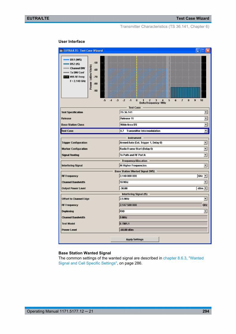
Test Case WizardEUTRA/LTE
294Operating Manual 1171.5177.12 ─ 21
User Interface
Base Station Wanted SignalThe common settings of the wanted signal are described in chapter 8.6.3, "WantedSignal and Cell Specific Settings", on page 286.
Transmitter Characteristics (TS 36.141, Chapter 6)
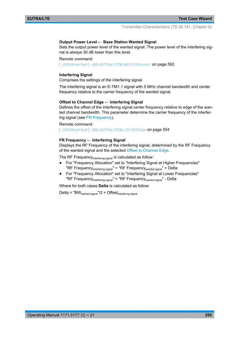
Test Case WizardEUTRA/LTE
295Operating Manual 1171.5177.12 ─ 21
Output Power Level ← Base Station Wanted SignalSets the output power level of the wanted signal. The power level of the interfering sig-nal is always 30 dB lower than this level.
Remote command: [: SOURce<hw>]: BB:EUTRa: TCW:WS:OUPLevel on page 562
Interfering SignalComprises the settings of the interfering signal.
The interfering signal is an E-TM1.1 signal with 5 MHz channel bandwidth and centerfrequency relative to the carrier frequency of the wanted signal.
Offset to Channel Edge ← Interfering SignalDefines the offset of the interfering signal center frequency relative to edge of the wan-ted channel bandwidth. This parameter determine the carrier frequency of the interfer-ing signal (see FR Frequency).
Remote command: [:SOURce<hw>]: BB:EUTRa:TCW: IS:OCEDge on page 554
FR Frequency ← Interfering SignalDisplays the RF Frequency of the interfering signal, determined by the RF Frequencyof the wanted signal and the selected Offset to Channel Edge.
The RF Frequencyinterfering signal is calculated as follow:● For "Frequency Allocation" set to "Interfering Signal at Higher Frequencies"
"RF Frequencyinterfering signal" = "RF Frequencywanted signal" + Delta● For "Frequency Allocation" set to "Interfering Signal at Lower Frequencies"
"RF Frequencyinterfering signal" = "RF Frequencywanted signal" - Delta
Where for both cases Delta is calculated as follow:
Delta = "BWwanted signal"/2 + Offsetinterfering signal
Transmitter Characteristics (TS 36.141, Chapter 6)
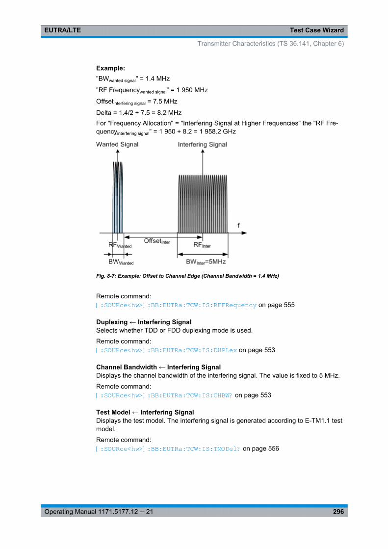
Test Case WizardEUTRA/LTE
296Operating Manual 1171.5177.12 ─ 21
Example: "BWwanted signal" = 1.4 MHz
"RF Frequencywanted signal" = 1 950 MHz
Offsetinterfering signal = 7.5 MHz
Delta = 1.4/2 + 7.5 = 8.2 MHzFor "Frequency Allocation" = "Interfering Signal at Higher Frequencies" the "RF Fre-quencyinterfering signal" = 1 950 + 8.2 = 1 958.2 GHz
Fig. 8-7: Example: Offset to Channel Edge (Channel Bandwidth = 1.4 MHz)
Remote command: [:SOURce<hw>]: BB: EUTRa:TCW: IS:RFFRequency on page 555
Duplexing ← Interfering SignalSelects whether TDD or FDD duplexing mode is used.
Remote command: [:SOURce<hw>]: BB:EUTRa: TCW:IS:DUPLex on page 553
Channel Bandwidth ← Interfering SignalDisplays the channel bandwidth of the interfering signal. The value is fixed to 5 MHz.
Remote command: [:SOURce<hw>]: BB:EUTRa: TCW:IS:CHBW? on page 553
Test Model ← Interfering SignalDisplays the test model. The interfering signal is generated according to E-TM1.1 testmodel.
Remote command: [:SOURce<hw>]: BB: EUTRa:TCW: IS:TMODel? on page 556
Transmitter Characteristics (TS 36.141, Chapter 6)
Test Case WizardEUTRA/LTE
297Operating Manual 1171.5177.12 ─ 21
Power Level ← Interfering SignalDisplays the power level of the interfering signal. The power level is always 30 dBbelow the Output Power Level of the wanted signal.
Remote command: [:SOURce<hw>]: BB:EUTRa: TCW:IS: PLEVel? on page 555
8.8 Receiver Characteristics (TS 36.141, Chapter 7)
Most of the receiver tests can be performed with the signal generator only, i.e. withoutadditional measurement equipment.
The receiver requirements are divided into the following main categories, intended to● Prove the receiver's ability to receive the wanted signal:
– chapter 8.8.4, "Test Case 7.2: Reference Sensitivity Level", on page 303– chapter 8.8.5, "Test Case 7.3: Dynamic range", on page 305
● Prove how susceptible the receiver is to different types of interfering signals:– chapter 8.8.6, "Test Case 7.4: In-channel selectivity (ICS)", on page 308– chapter 8.8.7, "Test Case 7.5A: Adjacent Channel Selectivity (ACS)",
on page 311– chapter 8.8.8, "Test Case 7.5B: Narrow-band blocking", on page 313– chapter 8.8.9, "Test Case 7.6: Blocking", on page 316– chapter 8.8.10, "Test Case 7.8: Receiver intermodulation ", on page 320
The several test cases shell cover a wide range of scenarios with different types ofimpairments on the wanted signal, that occur depending on the frequency offsetbetween the wanted and the interfering signal.
8.8.1 Prior Considerations
Fixed Reference Channels (FRC)
The receiver tests use fixed reference channels (FRC) as defined in 3GPP TS 36.141,Annex A "Reference Measurement channels".
The following FRCs are defined for the receiver tests:● FRC A1: A1-1 .. A1-5 (QPSK)● FRC A2: A2-1 .. A2-3 (16QAM)
Refer to table 7-11 for an overview of all supported FRC.
Receiver Characteristics (TS 36.141, Chapter 7)
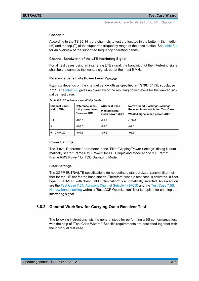
Test Case WizardEUTRA/LTE
298Operating Manual 1171.5177.12 ─ 21
Channels
According to the TS 36.141, the channels to test are located in the bottom (B), middle(M) and the top (T) of the supported frequency range of the base station. See table 8-4for an overview of the supported frequency operating bands.
Channel Bandwidth of the LTE Interfering Signal
For all test cases using an interfering LTE signal, the bandwidth of the interfering signalshall be the same as the wanted signal, but at the most 5 MHz.
Reference Sensitivity Power Level PREFSENS
PREFSENS depends on the channel bandwidth as specified in TS 36.104 [9], subclause7.2.1. The table 8-8 gives an overview of the resulting power levels for the wanted sig-nal per test case.
Table 8-8: BS reference sensitivity levels
Channel Band-width, MHz
Reference sensi-tivity power level,PREFSENS, dBm
ACS Test Case
Wanted signalmean power, dBm
Narrow-band Blocking/Blocking/Receiver Intermodulation Test Case
Wanted signal mean power, dBm
1.4 -106.8 -95.9 -100.8
3 -103.0 -95.0 -97.0
5 /10 /15 /20 -101.5 -95.5 -95.5
Power Settings
The "Level Reference" parameter in the "Filter/Clipping/Power Settings" dialog is auto-matically set to "Frame RMS Power" for FDD Duplexing Mode and to "UL Part ofFrame RMS Power" for TDD Duplexing Mode.
Filter Settings
The 3GPP EUTRA/LTE specifications do not define a standardized transmit filter nei-ther for the UE nor for the base station. Therefore, when a test case is activated, a filtertype EUTRA/LTE with "Best EVM Optimization" is automatically selected. An exceptionare the Test Case 7.5A: Adjacent Channel Selectivity (ACS) and the Test Case 7.5B:Narrow-band blocking wehre a "Best ACP Optimization" filter is applied for shaping theinterfering signal.
8.8.2 General Workflow for Carrying Out a Receiver Test
The following instructions lists the general steps for performing a BS conformance testwith the help of "Test Case Wizard". Specific requirements are described together withthe individual test case.
Receiver Characteristics (TS 36.141, Chapter 7)
Test Case WizardEUTRA/LTE
299Operating Manual 1171.5177.12 ─ 21
For detailed description about the configuration of the base station, refer to the corre-sponding description.
1. Connect the instrument and the DUT according to the corresponding test casesetup.See also chapter 8.4, "Standard Test Setups", on page 276.
2. Set the base station to the basic state
a) Initialize the base stationb) Set the frequencyc) Set the base station to receive the Fixed Reference Channel (for most receiver
test cases)
3. Preset the signal generator to ensure a defined instrument state.
4. Configure the test case wizard
a) Select "Baseband Block > EUTRA/LTE > Test Case Wizard".b) Select a test case, e.g. "TS 36.141: 7.3 Dynamic Range".c) Enter additional required parameters.d) Enter the test frequency (e.g. M). It must be the same as the base station has
been set to.e) Activate the settings with the "Apply Settings" button.
The signal generator is now ready to start signal generation
5. Switch on RF output
6. If required, make additional settings (e.g. in the "I/Q Mod" or "RF" block) or changetest case settings.
7. Start the measurement
a) Send a start trigger impulse from the base station to the signal generator.
The signal generator will start signal generation.
8. Calculate the result
The base station internally calculates the BER, BLER or Pd depending on the testcase. This value is compared to the required value.
8.8.3 Interfering Signal Settings
The following settings are available for almost all receiver tests, requiring an interferingsignal (IS). Specific parameters are listed together with the description of the corre-sponding test case.
Receiver Characteristics (TS 36.141, Chapter 7)
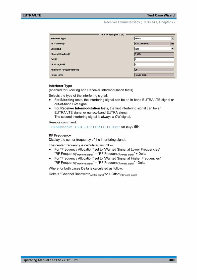
Test Case WizardEUTRA/LTE
300Operating Manual 1171.5177.12 ─ 21
Interferer Type(enabled for Blocking and Receiver Intermodulation tests)
Selects the type of the interfering signal:● For Blocking tests, the interfering signal can be an in-band EUTRA/LTE signal or
out-of-band CW signal.● For Receiver Intermodulation tests, the first interfering signal can be an
EUTRA/LTE signal or narrow-band EUTRA signal.The second interfering signal is always a CW signal.
Remote command: [:SOURce<hw>]: BB: EUTRa:TCW: IS:IFTYpe on page 554
RF FrequencyDisplay the center frequency of the interfering signal.
The center frequency is calculated as follow:● For "Frequency Allocation" set to "Wanted Signal at Lower Frequencies"
"RF Frequencyinterfering signal" = "RF Frequencywanted signal" + Delta● For "Frequency Allocation" set to "Wanted Signal at Higher Frequencies"
"RF Frequencyinterfering signal" = "RF Frequencywanted signal" - Delta
Where for both cases Delta is calculated as follow:
Delta = "Channel Bandwidthwanted signal"/2 + Offsetinterfering signal
Receiver Characteristics (TS 36.141, Chapter 7)
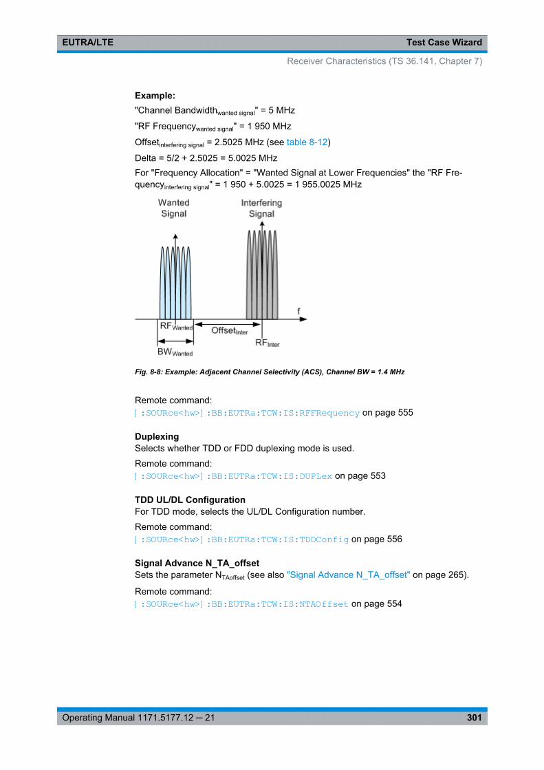
Test Case WizardEUTRA/LTE
301Operating Manual 1171.5177.12 ─ 21
Example: "Channel Bandwidthwanted signal" = 5 MHz
"RF Frequencywanted signal" = 1 950 MHz
Offsetinterfering signal = 2.5025 MHz (see table 8-12)
Delta = 5/2 + 2.5025 = 5.0025 MHzFor "Frequency Allocation" = "Wanted Signal at Lower Frequencies" the "RF Fre-quencyinterfering signal" = 1 950 + 5.0025 = 1 955.0025 MHz
Fig. 8-8: Example: Adjacent Channel Selectivity (ACS), Channel BW = 1.4 MHz
Remote command: [:SOURce<hw>]: BB: EUTRa:TCW: IS:RFFRequency on page 555
DuplexingSelects whether TDD or FDD duplexing mode is used.
Remote command: [:SOURce<hw>]: BB:EUTRa: TCW:IS:DUPLex on page 553
TDD UL/DL ConfigurationFor TDD mode, selects the UL/DL Configuration number.
Remote command: [:SOURce<hw>]: BB:EUTRa: TCW:IS: TDDConfig on page 556
Signal Advance N_TA_offsetSets the parameter NTAoffset (see also "Signal Advance N_TA_offset" on page 265).
Remote command: [:SOURce<hw>]: BB:EUTRa: TCW:IS: NTAOffset on page 554
Receiver Characteristics (TS 36.141, Chapter 7)
Test Case WizardEUTRA/LTE
302Operating Manual 1171.5177.12 ─ 21
Channel BandwidthDisplays the channel bandwidth of the interfering signal. The interfering signal has thesame bandwidth as the wanted signal, but at the most 5 MHz.
Remote command: [:SOURce<hw>]: BB:EUTRa: TCW:IS:CHBW? on page 553
Cell IDSets the Cell ID for the interfering signal.
Remote command: [:SOURce<hw>]: BB:EUTRa: TCW:IS: CLID on page 553
UE ID/n_RNTISets the UE ID/n_RNTI for the interfering signal.
Remote command: [:SOURce<hw>]: BB: EUTRa:TCW: IS:UEID on page 556
Number of Resource BlocksThe number of RBs used by the LTE interfering signal is set automatically:● For ACS and In-channel Selectivity measurements, the number of RBs depends
on the selected channel bandwidth for the wanted signal. The bandwidth of theinterfering signal is equal to the bandwidth allocated for the wanted signal, but atthe most 5 MHz.
● For Narrow-band Blocking tests, the interfering signal is a single resource blockLTE signal.
Remote command: [:SOURce<hw>]: BB:EUTRa: TCW:IS:NRBLock? on page 554
Offset VRB(Test Case 7.4 and 7.5 only)
The position of the RBs allocated by the LTE interfering signal is determined automati-cally, depending on the selected "Channel Bandwidth" and the RBs allocation of thewanted signal.
● For in-channel testing, the parameter "Offset VRB" is used to allocate the wantedand the interfering signal around the center frequency (see also figure 8-9).
● For ACS testing, the "Offset VRB" is fixed to 0.● For narrow band blocking testing, the "Offset VRB" is set in the way, that dep-
pending on the "Frequency Allocation" of the interfering signal, the narrow-bandLTE interfering signal is allocated at the most left or the most rigth subcarrier in theallocated channel bandwidth
Remote command: [:SOURce<hw>]: BB:EUTRa: TCW:IS: OVRB? on page 555
Frequency Shift m(Test Case 7.5 only)
Receiver Characteristics (TS 36.141, Chapter 7)
Test Case WizardEUTRA/LTE
303Operating Manual 1171.5177.12 ─ 21
By default, the narrow-band LTE interfering signal is allocated at the most left (interfer-ing signal at higher frequencies)/ most right (interfering signal at lower frequencies)subcarrier in the allocated channel bandwidth. However, the position of the interferingsignal can be set by means of the parameter "Frequency Shift m", i.e. the allocated RBcan be offset to a different center frequency (see figure 8-10).
The parameter Interfering RB Center Frequency displays the center frequency of theresource block the interfering signal is currently allocated on.
The value range of the parameter depends on the selected "Channel Bandwidth", asdefined in table 8-13.
Remote command: [:SOURce<hw>]: BB:EUTRa: TCW:IS:FRSHift on page 553
Interfering RB Center Frequency(for Narrow-band Block tests only)
Displays the center frequency of the single resource block interfering signal (see alsofigure 8-10).
Remote command: [:SOURce<hw>]: BB:EUTRa: TCW:IS:RBCFrequency on page 555
Power LevelThe power level of the interfering LTE signal is set automatically depending on theselected channel bandwidth.
Remote command: [: SOURce<hw>]: BB:EUTRa: TCW:IS:PLEVel? on page 555
8.8.4 Test Case 7.2: Reference Sensitivity Level
Test Purpose
To verify that at the BS Reference sensitivity level the throughput requirement shall bemet for a specified reference measurement channel [6].
Required Options
See chapter 8.2, "Basic Configuration", on page 273.
Test Setup
See chapter 8.4.1, "Standard Test Setup - One Path", on page 276
Short Description
The reference sensitivity level measurement is a test case that aims to verify the NoiseFigure of the receivers. The test case uses FRCs with QPSK modulation.
Receiver Characteristics (TS 36.141, Chapter 7)

Test Case WizardEUTRA/LTE
304Operating Manual 1171.5177.12 ─ 21
The test shall be done on three channels (B, M and T). The selected "Channel Band-width" determines the used FRC and the "Wanted Signal Power Level". For channelslarger than 5 MHz not all RBs are allocated; the position of the allocated RBs within theselected channel bandwidth can be adjusted by means of the parameter "Offset VRB".
For the parameter in the table 8-9 the throughput measured shall be equal or graterthan 95%.
Table 8-9: Reference sensitivity levels
Channel Bandwidth, MHz Reference MeasurementsChannel
Reference sensitivity powerlevel PREFSENS, dBm
1.4 FRC A1-1 -106.1
3 FRC A1-2 -102.3
5 / 10 / 15 / 20 FRC A1-3 -100.8
Receiver Characteristics (TS 36.141, Chapter 7)
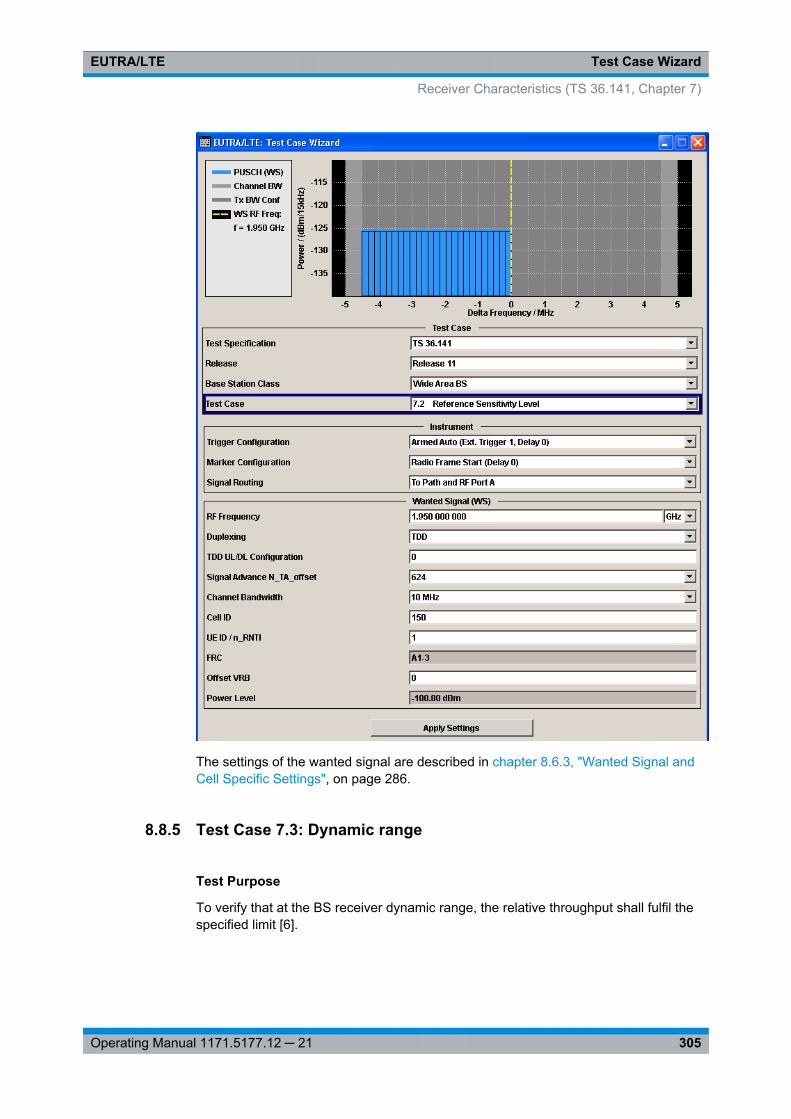
Test Case WizardEUTRA/LTE
305Operating Manual 1171.5177.12 ─ 21
The settings of the wanted signal are described in chapter 8.6.3, "Wanted Signal andCell Specific Settings", on page 286.
8.8.5 Test Case 7.3: Dynamic range
Test Purpose
To verify that at the BS receiver dynamic range, the relative throughput shall fulfil thespecified limit [6].
Receiver Characteristics (TS 36.141, Chapter 7)
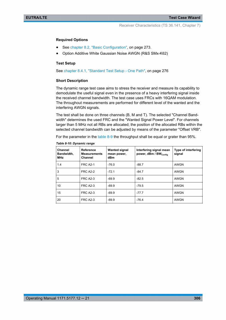
Test Case WizardEUTRA/LTE
306Operating Manual 1171.5177.12 ─ 21
Required Options
● See chapter 8.2, "Basic Configuration", on page 273.● Option Additive White Gaussian Noise AWGN (R&S SMx-K62)
Test Setup
See chapter 8.4.1, "Standard Test Setup - One Path", on page 276
Short Description
The dynamic range test case aims to stress the receiver and measure its capability todemodulate the useful signal even in the presence of a heavy interfering signal insidethe received channel bandwidth. The test case uses FRCs with 16QAM modulation.The throughout measurements are performed for different level of the wanted and theinterfering AWGN signals.
The test shall be done on three channels (B, M and T). The selected "Channel Band-width" determines the used FRC and the "Wanted Signal Power Level". For channelslarger than 5 MHz not all RBs are allocated; the position of the allocated RBs within theselected channel bandwidth can be adjusted by means of the parameter "Offset VRB".
For the parameter in the table 8-9 the throughput shall be equal or grater than 95%.
Table 8-10: Dynamic range
ChannelBandwidth,MHz
ReferenceMeasurementsChannel
Wanted signalmean power,dBm
Interfering signal meanpower, dBm / BWConfig
Type of interferingsignal
1.4 FRC A2-1 -76.0 -88.7 AWGN
3 FRC A2-2 -72.1 -84.7 AWGN
5 FRC A2-3 -69.9 -82.5 AWGN
10 FRC A2-3 -69.9 -79.5 AWGN
15 FRC A2-3 -69.9 -77.7 AWGN
20 FRC A2-3 -69.9 -76.4 AWGN
Receiver Characteristics (TS 36.141, Chapter 7)
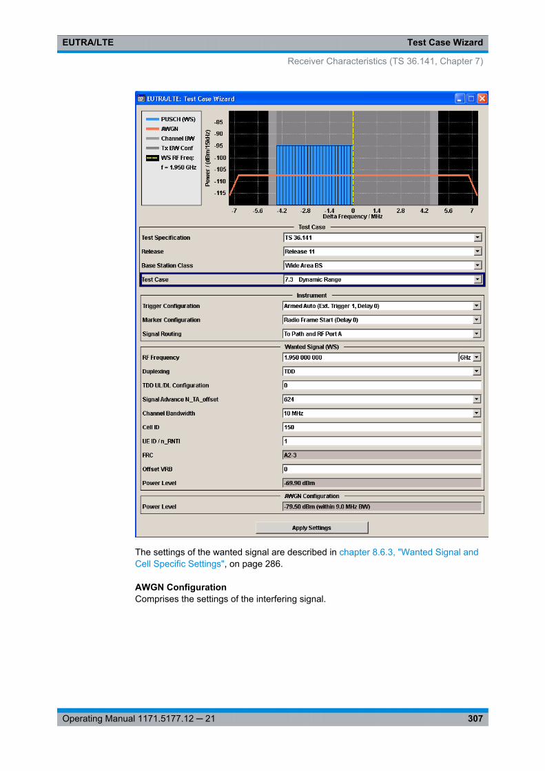
Test Case WizardEUTRA/LTE
307Operating Manual 1171.5177.12 ─ 21
The settings of the wanted signal are described in chapter 8.6.3, "Wanted Signal andCell Specific Settings", on page 286.
AWGN ConfigurationComprises the settings of the interfering signal.
Receiver Characteristics (TS 36.141, Chapter 7)
Test Case WizardEUTRA/LTE
308Operating Manual 1171.5177.12 ─ 21
Power Level ← AWGN ConfigurationDisplays the power level of the AWGN signal. The value is set automatically accordingto table 8-10 and depending on the selected Channel Bandwidth.
Remote command: [:SOURce<hw>]: BB:EUTRa: TCW:AWGN: PLEVel? on page 550
8.8.6 Test Case 7.4: In-channel selectivity (ICS)
Test Purpose
The purpose of this test is to verify the BS receiver ability to suppress the IQ leakage[6].
Required Options
The required options depend on whether the test will be performed with an instrumentequipped with one or two paths.● Instrument equipped with one path, e.g. R&S SMU/SMJ/SMATE/SMBV:
See chapter 8.2, "Basic Configuration", on page 273.● Instument equipped with two paths, e.g. R&S SMU/SMATE:
– See chapter 8.2, "Basic Configuration", on page 273.– Option Second RF path (R&S SMx-B20x)– Second Option Baseband Generator (R&S SMx-B10)– Second Option Baseband Main Module (R&S SMx-B13)– Second Option Digital Standard EUTRA/LTE (R&S SMx-K55)
Test Setup
See chapter 8.4.1, "Standard Test Setup - One Path", on page 276 or chapter 8.4.2,"Standard Test Setup - Two Paths", on page 276
Short Description
In-channel selectivity (ICS) is a measure of the receiver ability to receive a "weak"wanted signal at its assigned Resource Block locations in the presence of a "strong"interfering signal. The interfering signal shall be an EUTRA/LTE signal with the samebandwidth as the wanted signal, but at the most 5 MHz. The wanted and the interferingsignal are allocated around the center frequency (see figure 8-9); to swap the positionof the wanted and interfering signal, use the parameter "Frequency Allocation".
Receiver Characteristics (TS 36.141, Chapter 7)
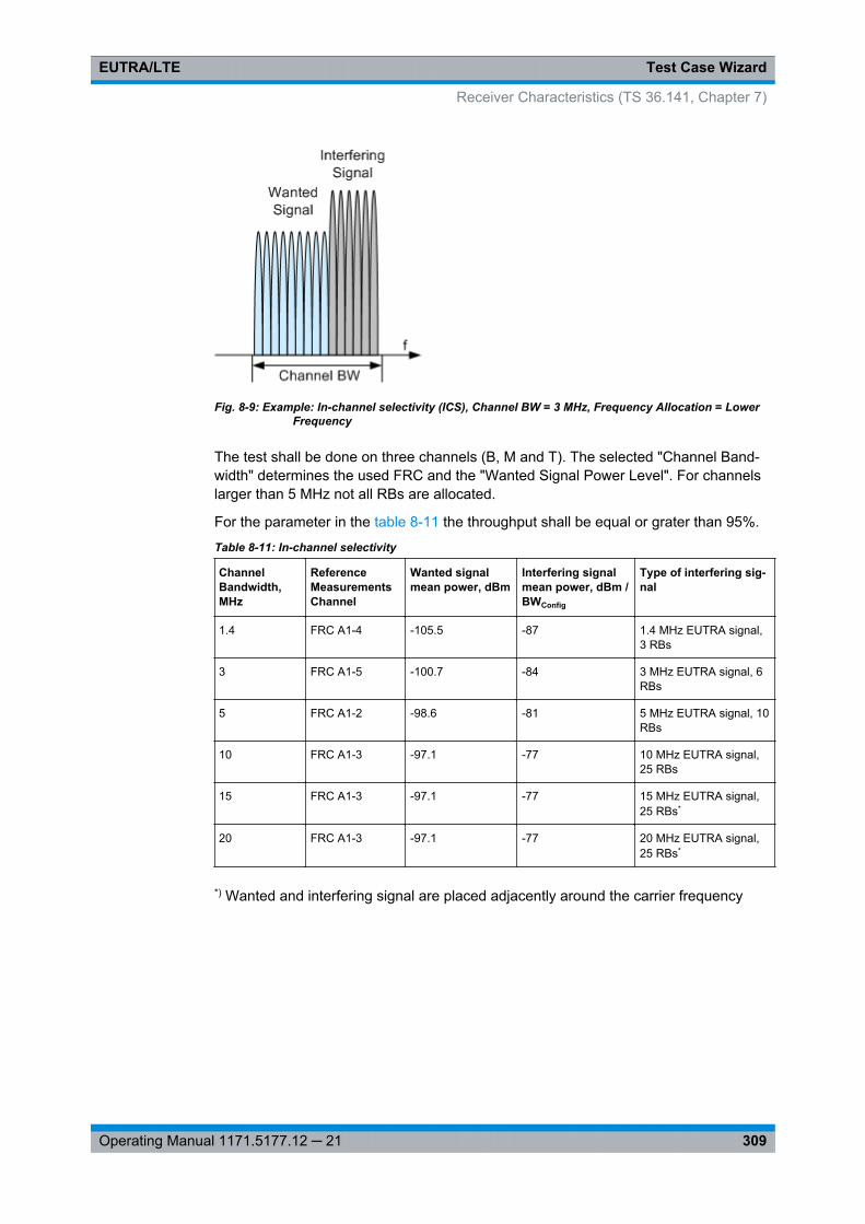
Test Case WizardEUTRA/LTE
309Operating Manual 1171.5177.12 ─ 21
Fig. 8-9: Example: In-channel selectivity (ICS), Channel BW = 3 MHz, Frequency Allocation = LowerFrequency
The test shall be done on three channels (B, M and T). The selected "Channel Band-width" determines the used FRC and the "Wanted Signal Power Level". For channelslarger than 5 MHz not all RBs are allocated.
For the parameter in the table 8-11 the throughput shall be equal or grater than 95%.
Table 8-11: In-channel selectivity
ChannelBandwidth,MHz
ReferenceMeasurementsChannel
Wanted signalmean power, dBm
Interfering signalmean power, dBm /BWConfig
Type of interfering sig-nal
1.4 FRC A1-4 -105.5 -87 1.4 MHz EUTRA signal,3 RBs
3 FRC A1-5 -100.7 -84 3 MHz EUTRA signal, 6RBs
5 FRC A1-2 -98.6 -81 5 MHz EUTRA signal, 10RBs
10 FRC A1-3 -97.1 -77 10 MHz EUTRA signal,25 RBs
15 FRC A1-3 -97.1 -77 15 MHz EUTRA signal,25 RBs*
20 FRC A1-3 -97.1 -77 20 MHz EUTRA signal,25 RBs*
*) Wanted and interfering signal are placed adjacently around the carrier frequency
Receiver Characteristics (TS 36.141, Chapter 7)
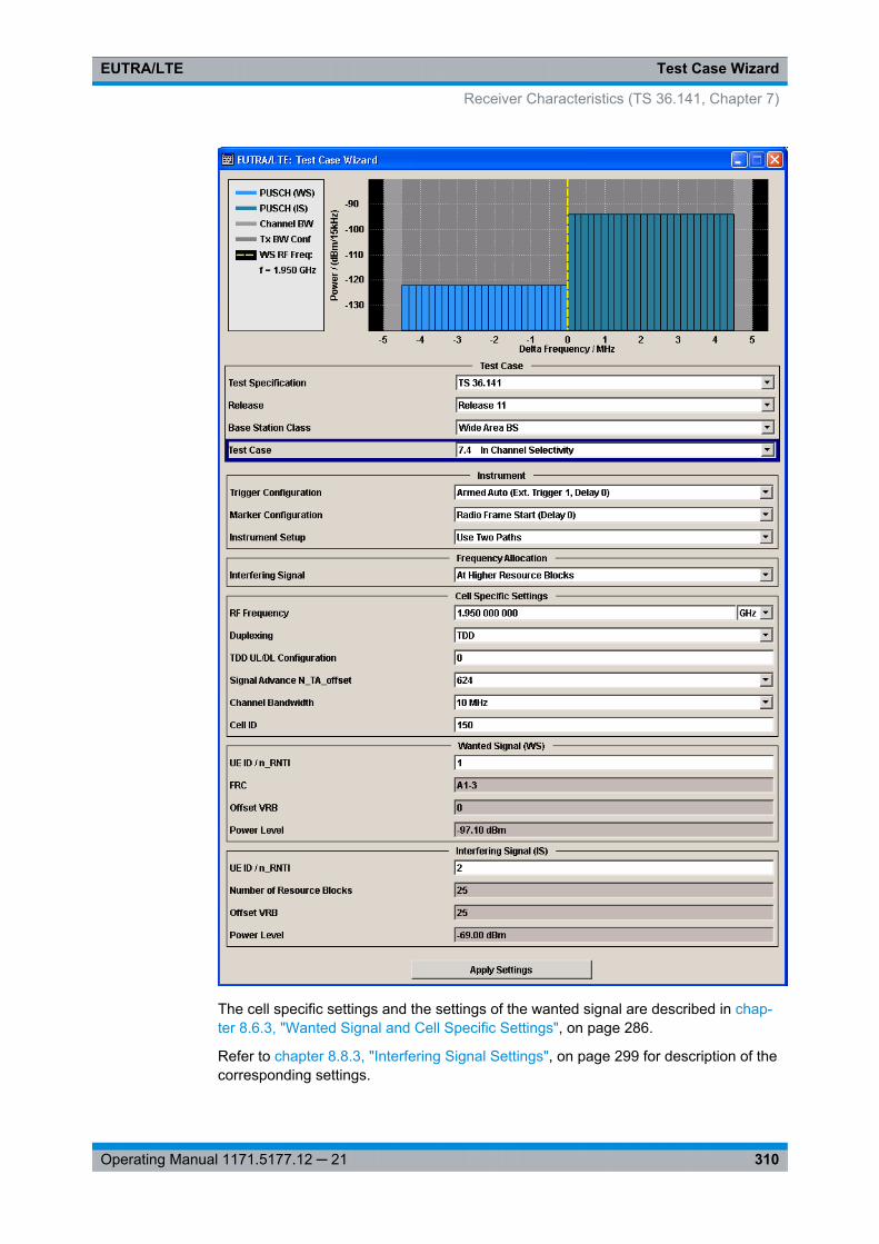
Test Case WizardEUTRA/LTE
310Operating Manual 1171.5177.12 ─ 21
The cell specific settings and the settings of the wanted signal are described in chap-ter 8.6.3, "Wanted Signal and Cell Specific Settings", on page 286.
Refer to chapter 8.8.3, "Interfering Signal Settings", on page 299 for description of thecorresponding settings.
Receiver Characteristics (TS 36.141, Chapter 7)
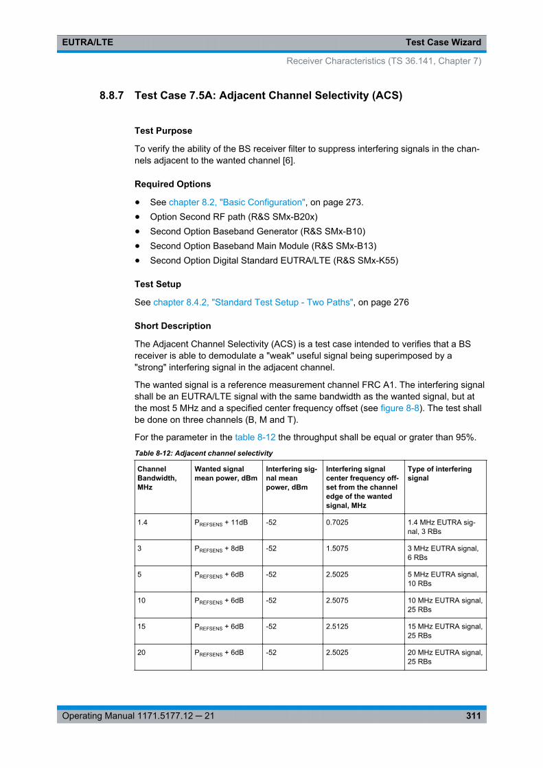
Test Case WizardEUTRA/LTE
311Operating Manual 1171.5177.12 ─ 21
8.8.7 Test Case 7.5A: Adjacent Channel Selectivity (ACS)
Test Purpose
To verify the ability of the BS receiver filter to suppress interfering signals in the chan-nels adjacent to the wanted channel [6].
Required Options
● See chapter 8.2, "Basic Configuration", on page 273.● Option Second RF path (R&S SMx-B20x)● Second Option Baseband Generator (R&S SMx-B10)● Second Option Baseband Main Module (R&S SMx-B13)● Second Option Digital Standard EUTRA/LTE (R&S SMx-K55)
Test Setup
See chapter 8.4.2, "Standard Test Setup - Two Paths", on page 276
Short Description
The Adjacent Channel Selectivity (ACS) is a test case intended to verifies that a BSreceiver is able to demodulate a "weak" useful signal being superimposed by a"strong" interfering signal in the adjacent channel.
The wanted signal is a reference measurement channel FRC A1. The interfering signalshall be an EUTRA/LTE signal with the same bandwidth as the wanted signal, but atthe most 5 MHz and a specified center frequency offset (see figure 8-8). The test shallbe done on three channels (B, M and T).
For the parameter in the table 8-12 the throughput shall be equal or grater than 95%.
Table 8-12: Adjacent channel selectivity
ChannelBandwidth,MHz
Wanted signalmean power, dBm
Interfering sig-nal meanpower, dBm
Interfering signalcenter frequency off-set from the channeledge of the wantedsignal, MHz
Type of interferingsignal
1.4 PREFSENS + 11dB -52 0.7025 1.4 MHz EUTRA sig-nal, 3 RBs
3 PREFSENS + 8dB -52 1.5075 3 MHz EUTRA signal,6 RBs
5 PREFSENS + 6dB -52 2.5025 5 MHz EUTRA signal,10 RBs
10 PREFSENS + 6dB -52 2.5075 10 MHz EUTRA signal,25 RBs
15 PREFSENS + 6dB -52 2.5125 15 MHz EUTRA signal,25 RBs
20 PREFSENS + 6dB -52 2.5025 20 MHz EUTRA signal,25 RBs
Receiver Characteristics (TS 36.141, Chapter 7)
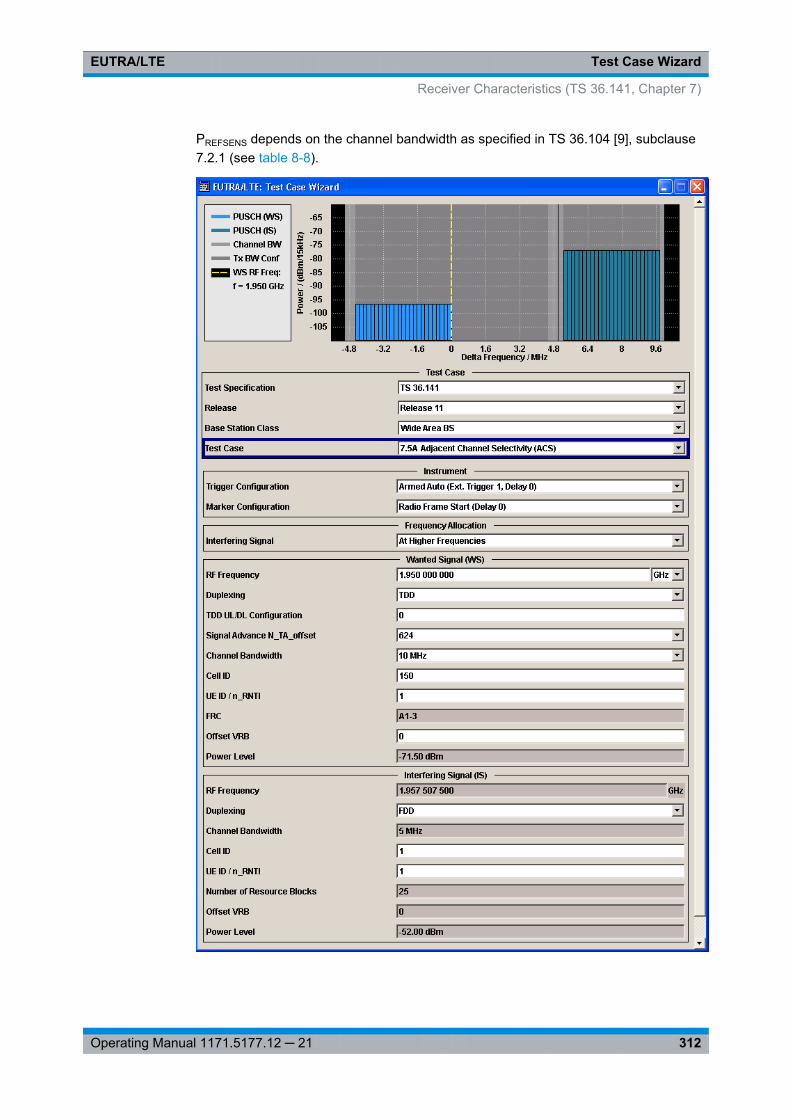
Test Case WizardEUTRA/LTE
312Operating Manual 1171.5177.12 ─ 21
PREFSENS depends on the channel bandwidth as specified in TS 36.104 [9], subclause7.2.1 (see table 8-8).
Receiver Characteristics (TS 36.141, Chapter 7)

Test Case WizardEUTRA/LTE
313Operating Manual 1171.5177.12 ─ 21
The settings of the wanted signal are described in chapter 8.6.3, "Wanted Signal andCell Specific Settings", on page 286.
Refer to chapter 8.8.3, "Interfering Signal Settings", on page 299 for description of thecorresponding settings.
8.8.8 Test Case 7.5B: Narrow-band blocking
Test Purpose
To verify the ability of the BS receiver filter to suppress interfering signals in the chan-nels adjacent to the wanted channel [6].
Required Options
● See chapter 8.2, "Basic Configuration", on page 273.● Option Second RF path (R&S SMx-B20x)● Second Option Baseband Generator (R&S SMx-B10)● Second Option Baseband Main Module (R&S SMx-B13)● Second Option Digital Standard EUTRA/LTE (R&S SMx-K55)
Test Setup
See chapter 8.4.2, "Standard Test Setup - Two Paths", on page 276
Short Description
The Narrow-band Blocking is a test case intended to verifies that a BS receiver is ableto demodulate a "weak" useful signal being superimposed by a "strong" narrow-bandinterfering signal in the adjacent channel. The wanted signal is a reference measure-ment channel FRC A1. The interfering signal is a single resource block EUTRA/LTEsignal in a channel with the same bandwidth as the wanted signal, but at the most 5MHz. The interfering signal is located at a specified center frequency offset and adja-cently to the channel edge of the wanted signal (see figure 8-10).
Receiver Characteristics (TS 36.141, Chapter 7)
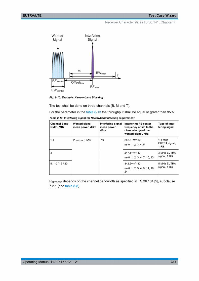
Test Case WizardEUTRA/LTE
314Operating Manual 1171.5177.12 ─ 21
Fig. 8-10: Example: Narrow-band Blocking
The test shall be done on three channels (B, M and T).
For the parameter in the table 8-13 the throughput shall be equal or grater than 95%.
Table 8-13: Interfering signal for Narrowband blocking requirement
Channel Band-width, MHz
Wanted signalmean power, dBm
Interfering signalmean power,dBm
Interfering RB centerfrequency offset to thechannel edge of thewanted signal, kHz
Type of inter-fering signal
1.4 PREFSENS + 6dB -49 252.5+m*180,
m=0, 1, 2, 3, 4, 5
1.4 MHzEUTRA signal,1 RB
3 247.5+m*180,
m=0, 1, 2, 3, 4, 7, 10, 13
3 MHz EUTRAsignal, 1 RB
5 / 10 / 15 / 20 342.5+m*180,
m=0, 1, 2, 3, 4, 9, 14, 19,24
5 MHz EUTRAsignal, 1 RB
PREFSENS depends on the channel bandwidth as specified in TS 36.104 [9], subclause7.2.1 (see table 8-8).
Receiver Characteristics (TS 36.141, Chapter 7)
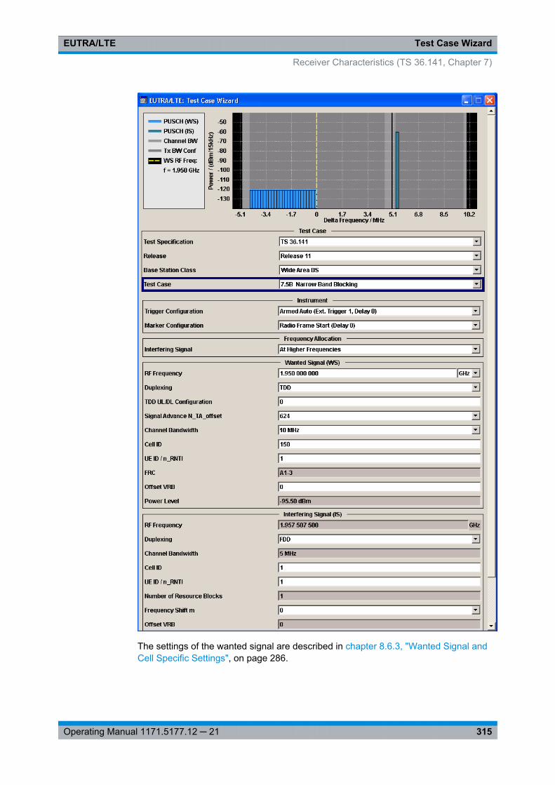
Test Case WizardEUTRA/LTE
315Operating Manual 1171.5177.12 ─ 21
The settings of the wanted signal are described in chapter 8.6.3, "Wanted Signal andCell Specific Settings", on page 286.
Receiver Characteristics (TS 36.141, Chapter 7)
Test Case WizardEUTRA/LTE
316Operating Manual 1171.5177.12 ─ 21
Refer to chapter 8.8.3, "Interfering Signal Settings", on page 299 for description of thecorresponding settings.
8.8.9 Test Case 7.6: Blocking
Test Purpose
The test stresses the ability of the BS receiver to withstand high-level interference fromunwanted signals at specified frequency offsets without undue degradation of its sensi-tivity [6].
Required Options
The following options are sufficient for tests with CW interfering signal:● See chapter 8.2, "Basic Configuration", on page 273.● Option Second RF path (R&S SMx-B20x)
Additionaly, the following options are necessary for tests with LTE interfering signal:● Second Option Baseband Generator (R&S SMx-B10)● Second Option Baseband Main Module (R&S SMx-B13)● Second Option Digital Standard EUTRA/LTE (R&S SMx-K55)
Test Setup
The blocking test using a EUTRA/LTE interfering signal can be performed with oneinstrument, see chapter 8.4.2, "Standard Test Setup - Two Paths", on page 276. Thissetup can also be used for the CW interfering signal case but only for the CW signalswith up to 3 GHz or 6 GHz carrier, depending on the installed option. For tests with CWwith frequency greater than 6 GHz a second signal generator is necessary, like R&SSMF for instance.
Short Description
The blocking characteristics is a test case that verifies the ability of the receiver todemodulate a wanted signal in the presence of a strong interfering signal. The test issplit into two scenarios:
● Test of in-band blocking, performed with an LTE interfering signal inside the oper-ating band (seetable 8-4 ), but not adjacent to the wanted signal.
● Test of out-of-band blocking, performed with a CW interfering signal with 1 MHz upto 12.750 GHz.There is an additional (optional) blocking requirements for co-location with otherbase station.
Receiver Characteristics (TS 36.141, Chapter 7)
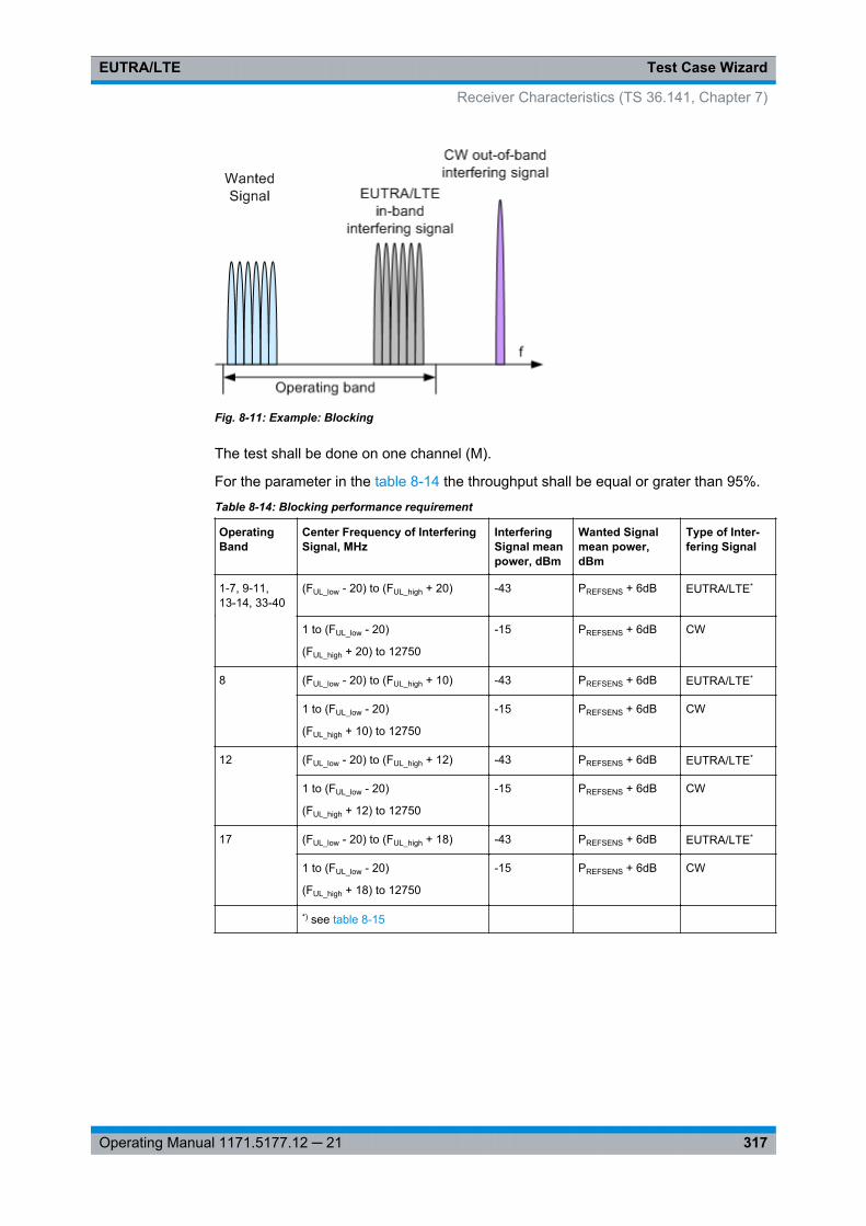
Test Case WizardEUTRA/LTE
317Operating Manual 1171.5177.12 ─ 21
Fig. 8-11: Example: Blocking
The test shall be done on one channel (M).
For the parameter in the table 8-14 the throughput shall be equal or grater than 95%.
Table 8-14: Blocking performance requirement
OperatingBand
Center Frequency of InterferingSignal, MHz
InterferingSignal meanpower, dBm
Wanted Signalmean power,dBm
Type of Inter-fering Signal
1-7, 9-11,13-14, 33-40
(FUL_low - 20) to (FUL_high + 20) -43 PREFSENS + 6dB EUTRA/LTE*
1 to (FUL_low - 20)
(FUL_high + 20) to 12750
-15 PREFSENS + 6dB CW
8 (FUL_low - 20) to (FUL_high + 10) -43 PREFSENS + 6dB EUTRA/LTE*
1 to (FUL_low - 20)
(FUL_high + 10) to 12750
-15 PREFSENS + 6dB CW
12 (FUL_low - 20) to (FUL_high + 12) -43 PREFSENS + 6dB EUTRA/LTE*
1 to (FUL_low - 20)
(FUL_high + 12) to 12750
-15 PREFSENS + 6dB CW
17 (FUL_low - 20) to (FUL_high + 18) -43 PREFSENS + 6dB EUTRA/LTE*
1 to (FUL_low - 20)
(FUL_high + 18) to 12750
-15 PREFSENS + 6dB CW
*) see table 8-15
Receiver Characteristics (TS 36.141, Chapter 7)
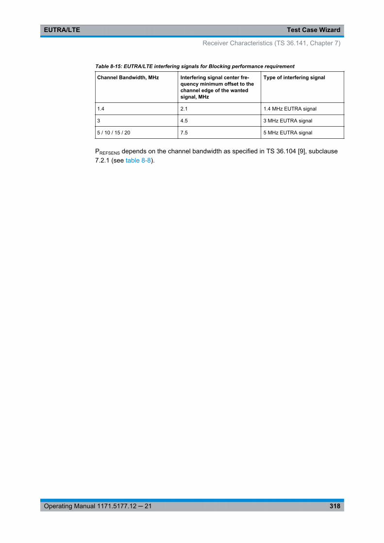
Test Case WizardEUTRA/LTE
318Operating Manual 1171.5177.12 ─ 21
Table 8-15: EUTRA/LTE interfering signals for Blocking performance requirement
Channel Bandwidth, MHz Interfering signal center fre-quency minimum offset to thechannel edge of the wantedsignal, MHz
Type of interfering signal
1.4 2.1 1.4 MHz EUTRA signal
3 4.5 3 MHz EUTRA signal
5 / 10 / 15 / 20 7.5 5 MHz EUTRA signal
PREFSENS depends on the channel bandwidth as specified in TS 36.104 [9], subclause7.2.1 (see table 8-8).
Receiver Characteristics (TS 36.141, Chapter 7)
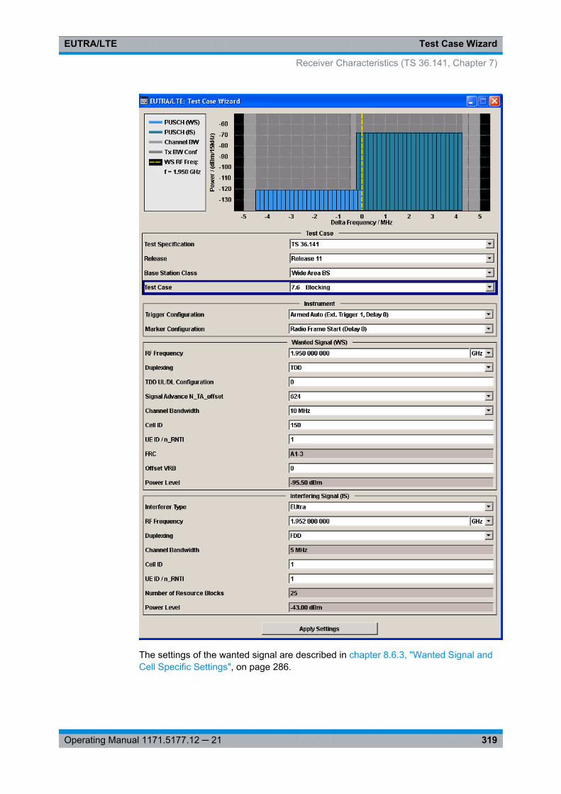
Test Case WizardEUTRA/LTE
319Operating Manual 1171.5177.12 ─ 21
The settings of the wanted signal are described in chapter 8.6.3, "Wanted Signal andCell Specific Settings", on page 286.
Receiver Characteristics (TS 36.141, Chapter 7)
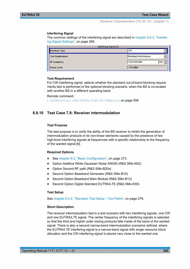
Test Case WizardEUTRA/LTE
320Operating Manual 1171.5177.12 ─ 21
Interfering SignalThe common settings of the interfering signal are described in chapter 8.8.3, "Interfer-ing Signal Settings", on page 299.
Test RequirementFor CW interfering signal, selects whether the standard out-of-band blocking require-ments test is performed or the optional blocking scenario, when the BS is co-locatedwith another BS in a different operating band.
Remote command: [:SOURce<hw>]: BB:EUTRa: TCW:IS: TREQuire on page 556
8.8.10 Test Case 7.8: Receiver intermodulation
Test Purpose
The test purpose is to verify the ability of the BS receiver to inhibit the generation ofintermodulation products in its non-linear elements caused by the presence of twohigh-level interfering signals at frequencies with a specific relationship to the frequencyof the wanted signal [6].
Required Options
● See chapter 8.2, "Basic Configuration", on page 273.● Option Additive White Gaussian Noise AWGN (R&S SMx-K62)● Option Second RF path (R&S SMx-B20x)● Second Option Baseband Generator (R&S SMx-B10)● Second Option Baseband Main Module (R&S SMx-B13)● Second Option Digital Standard EUTRA/LTE (R&S SMx-K55)
Test Setup
See chapter 8.4.2, "Standard Test Setup - Two Paths", on page 276.
Short Description
The receiver intermodulation test is a test scenario with two interfering signals, one CWand one EUTRA/LTE signal. The center frequency of the interfering signals is selectedso that the third and higher order mixing products falls inside of the band of the wantedsignal. There is also a second narrow-band intermodulation scenarios defined, wherethe EUTRA/LTE interfering signal is a narrow-band signal with single resource blockallocation and the CW interfering signal is placed very close to the wanted one.
Receiver Characteristics (TS 36.141, Chapter 7)
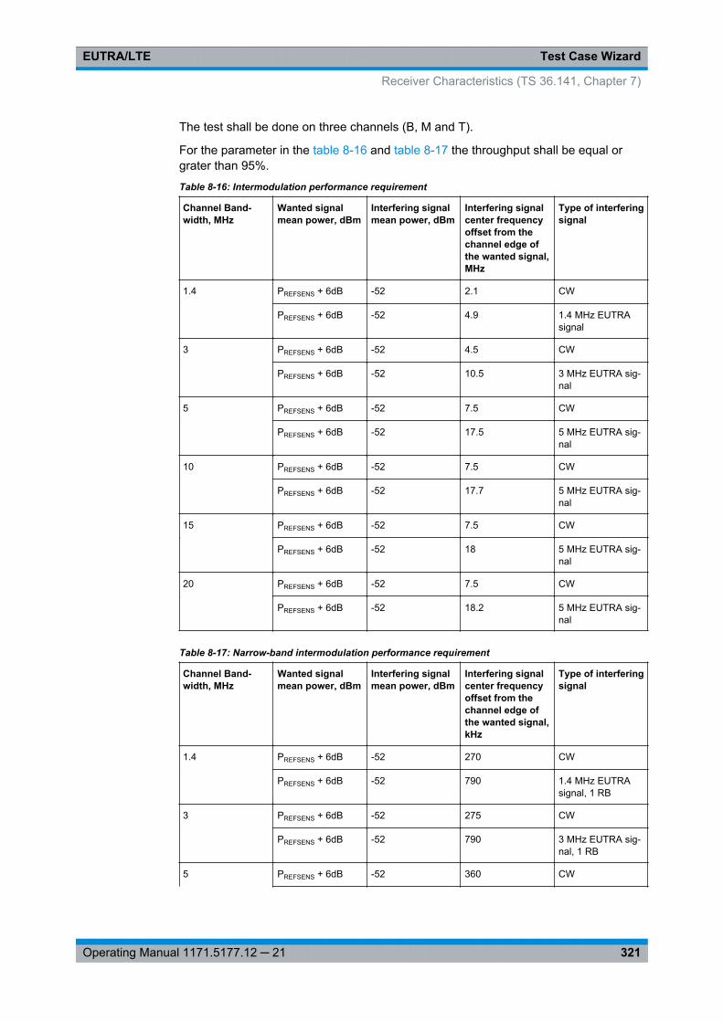
Test Case WizardEUTRA/LTE
321Operating Manual 1171.5177.12 ─ 21
The test shall be done on three channels (B, M and T).
For the parameter in the table 8-16 and table 8-17 the throughput shall be equal orgrater than 95%.
Table 8-16: Intermodulation performance requirement
Channel Band-width, MHz
Wanted signalmean power, dBm
Interfering signalmean power, dBm
Interfering signalcenter frequencyoffset from thechannel edge ofthe wanted signal,MHz
Type of interferingsignal
1.4 PREFSENS + 6dB -52 2.1 CW
PREFSENS + 6dB -52 4.9 1.4 MHz EUTRAsignal
3 PREFSENS + 6dB -52 4.5 CW
PREFSENS + 6dB -52 10.5 3 MHz EUTRA sig-nal
5 PREFSENS + 6dB -52 7.5 CW
PREFSENS + 6dB -52 17.5 5 MHz EUTRA sig-nal
10 PREFSENS + 6dB -52 7.5 CW
PREFSENS + 6dB -52 17.7 5 MHz EUTRA sig-nal
15 PREFSENS + 6dB -52 7.5 CW
PREFSENS + 6dB -52 18 5 MHz EUTRA sig-nal
20 PREFSENS + 6dB -52 7.5 CW
PREFSENS + 6dB -52 18.2 5 MHz EUTRA sig-nal
Table 8-17: Narrow-band intermodulation performance requirement
Channel Band-width, MHz
Wanted signalmean power, dBm
Interfering signalmean power, dBm
Interfering signalcenter frequencyoffset from thechannel edge ofthe wanted signal,kHz
Type of interferingsignal
1.4 PREFSENS + 6dB -52 270 CW
PREFSENS + 6dB -52 790 1.4 MHz EUTRAsignal, 1 RB
3 PREFSENS + 6dB -52 275 CW
PREFSENS + 6dB -52 790 3 MHz EUTRA sig-nal, 1 RB
5 PREFSENS + 6dB -52 360 CW
Receiver Characteristics (TS 36.141, Chapter 7)
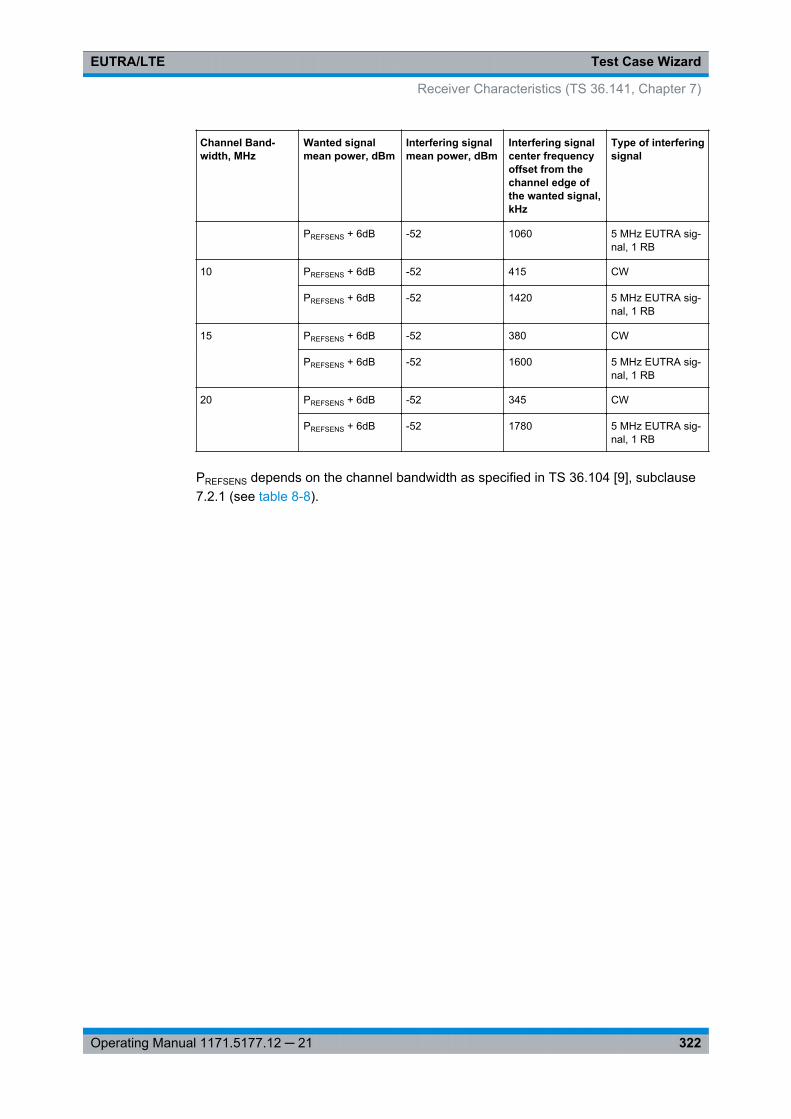
Test Case WizardEUTRA/LTE
322Operating Manual 1171.5177.12 ─ 21
Channel Band-width, MHz
Wanted signalmean power, dBm
Interfering signalmean power, dBm
Interfering signalcenter frequencyoffset from thechannel edge ofthe wanted signal,kHz
Type of interferingsignal
PREFSENS + 6dB -52 1060 5 MHz EUTRA sig-nal, 1 RB
10 PREFSENS + 6dB -52 415 CW
PREFSENS + 6dB -52 1420 5 MHz EUTRA sig-nal, 1 RB
15 PREFSENS + 6dB -52 380 CW
PREFSENS + 6dB -52 1600 5 MHz EUTRA sig-nal, 1 RB
20 PREFSENS + 6dB -52 345 CW
PREFSENS + 6dB -52 1780 5 MHz EUTRA sig-nal, 1 RB
PREFSENS depends on the channel bandwidth as specified in TS 36.104 [9], subclause7.2.1 (see table 8-8).
Receiver Characteristics (TS 36.141, Chapter 7)
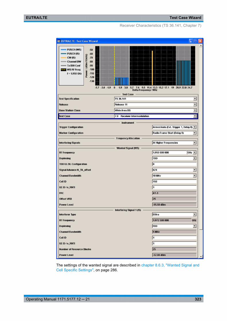
Test Case WizardEUTRA/LTE
323Operating Manual 1171.5177.12 ─ 21
The settings of the wanted signal are described in chapter 8.6.3, "Wanted Signal andCell Specific Settings", on page 286.
Receiver Characteristics (TS 36.141, Chapter 7)
Test Case WizardEUTRA/LTE
324Operating Manual 1171.5177.12 ─ 21
Refer to chapter 8.8.3, "Interfering Signal Settings", on page 299 for description of thecorresponding settings.
8.9 Performance Requirements (TS 36.141, Chapter 8)
The BS RF performance requirements are divided into three main groups:● Performance requirements for PUSCH, see
– chapter 8.9.3, "Test Case 8.2.1: PUSCH in multipath fading propagation condi-tions", on page 328
– chapter 8.9.4, "Test Case 8.2.2: UL timing adjustment", on page 332– chapter 8.9.5, "Test Case 8.2.3: HARQ-ACK multiplexed on PUSCH",
on page 336– chapter 8.9.6, "Test Case 8.2.4: High Speed Train conditions", on page 339
● Performance requirements for PUCCH– chapter 8.9.7, "Test Case 8.3.1: ACK missed detection for single user PUCCH
format 1a", on page 342– chapter 8.9.8, "Test Case 8.3.2: CQI performance requirements for PUCCH
format 2", on page 345– chapter 8.9.9, "Test Case 8.3.3: ACK missed detection for multi user PUCCH
format 1a", on page 347– chapter 8.9.10, "Test Case 8.3.4: ACK missed detection for PUCCH format 1b,
channel selection", on page 352– chapter 8.9.11, "Test Case 8.3.5: ACK missed detection for PUCCH format 3",
on page 355– chapter 8.9.12, "Test Case 8.3.6: NACK to ACK detection for PUCCH format
3", on page 358– chapter 8.9.13, "Test Case 8.3.9: CQI Performance for PUCCH format 2 with
DTX detection", on page 361● Performance requirements for PRACH
– chapter 8.9.14, "Test Case 8.4.1: PRACH false alarm probability and misseddetection", on page 363
8.9.1 Prior Considerations
Fixed Reference Channels (FRC)
The receiver tests use fixed reference channels (FRC) as defined in 3GPP TS 36.141,Annex A "Reference Measurement channels".
The following FRCs are defined for the performance tests:● FRC A3: A3-1 .. A3-7 (QPSK)● FRC A4: A4-1 .. A4-8 (16QAM)● FRC A5: A5-1 .. A5-7 (64QAM)
Performance Requirements (TS 36.141, Chapter 8)

Test Case WizardEUTRA/LTE
325Operating Manual 1171.5177.12 ─ 21
● FRC A7: A7-1 .. A7-6 (16QAM for UL timing adjustment)● FRC A8: A8-1 .. A8-6 (QPSK for UL timing adjustment)
Refer to table 7-11 for an overview of all supported FRC.
Channels
According to the TS 36.141, the channels to test are located in the bottom (B), middle(M) and the top (T) of the supported frequency range of the base station. See table 8-4for an overview of the supported frequency operating bands.
Power Settings
The "Level Reference" parameter in the "Filter/Clipping/Power Settings" dialog is auto-matically set to "UL Part of Frame RMS Power".
Filter Settings
The 3GPP EUTRA/LTE specifications do not define a standardized transmit filter nei-ther for the UE nor for the base station. Therefore, when a test case is activated, a filtertype EUTRA/LTE with "Best EVM Optimization" is automatically selected.
AWGN Power Level
The performance requirements tests are performed for a given SNR where the AWGNpower level is determined per channel bandwidth and test case according totable 8-18.
Table 8-18: AWGN power level
Channel bandwidth,MHz
AWGN power level
PUSCH tests
AWGN power level
PUCCH and PRACH tests
1.4 -92.7 dBm / 1.08 MHz -98.7 dBm / 1.08 MHz
3 -88.7 dBm / 2.7 MHz -85.7 dBm / 2.7 MHz
5 -86.5 dBm / 4.5 MHz -83.5 dBm / 4.5 MHz
10 -83.5 dBm / 9 MHz -80.5 dBm / 9 MHz
15 -81.7 dBm / 13.5 MHz -78.7 dBm / 13.5 MHz
20 -80.4 dBm / 18 MHz -77.4 dBm / 18 MHz
SNR Correction Factor
The SNR correction factor is applied for FRCs with not fully allocated RBs and iscalculated as follow:
SNRCorrectionFactor=10*log10(#Allocated RBs/#Possible RBs), dB
Performance Requirements (TS 36.141, Chapter 8)
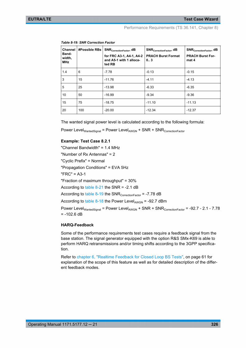
Test Case WizardEUTRA/LTE
326Operating Manual 1171.5177.12 ─ 21
Table 8-19: SNR Correction Factor
ChannelBand-width,MHz
#Possible RBs SNRCorrectionFactor, dB
for FRC A3-1, A4-1, A4-2and A5-1 with 1 alloca-ted RB
SNRCorrectionFactor, dB
PRACH Burst Format0.. 3
SNRCorrectionFactor, dB
PRACH Burst For-mat 4
1.4 6 -7.78 -0.13 -0.15
3 15 -11.76 -4.11 -4.13
5 25 -13.98 -6.33 -6.35
10 50 -16.99 -9.34 -9.36
15 75 -18.75 -11.10 -11.13
20 100 -20.00 -12.34 -12.37
The wanted signal power level is calculated according to the following formula:
Power LevelWantedSignal = Power LevelAWGN + SNR + SNRCorrectionFactor
Example: Test Case 8.2.1"Channel Bandwidth" = 1.4 MHz"Number of Rx Antennas" = 2"Cyclic Prefix" = Normal"Propagation Conditions" = EVA 5Hz"FRC" = A3-1"Fraction of maximum throughput" = 30%According to table 8-21 the SNR = -2.1 dBAccording to table 8-19 the SNRCorrectionFactor = -7.78 dB
According to table 8-18 the Power LevelAWGN = -92.7 dBm
Power LevelWantedSignal = Power LevelAWGN + SNR + SNRCorrectionFactor = -92.7 - 2.1 - 7.78= -102.6 dB
HARQ-Feedback
Some of the performance requirements test cases require a feedback signal from thebase station. The signal generator equipped with the option R&S SMx-K69 is able toperform HARQ retransmissions and/or timing shifts according to the 3GPP specifica-tion.
Refer to chapter 6, "Realtime Feedback for Closed Loop BS Tests", on page 61 forexplanation of the scope of this feature as well as for detailed description of the differ-ent feedback modes.
Performance Requirements (TS 36.141, Chapter 8)
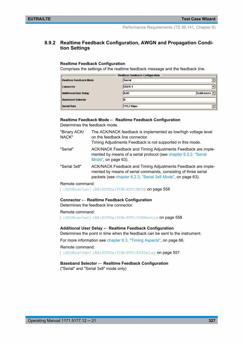
Test Case WizardEUTRA/LTE
327Operating Manual 1171.5177.12 ─ 21
8.9.2 Realtime Feedback Configuration, AWGN and Propagation Condi-tion Settings
Realtime Feedback ConfigurationComprises the settings of the realtime feedback message and the feedback line.
Realtime Feedback Mode ← Realtime Feedback ConfigurationDetermines the feedback mode.
"Binary ACK/NACK"
The ACK/NACK feedback is implemented as low/high voltage levelon the feedback line connector.Timing Adjustments Feedback is not supported in this mode.
"Serial" ACK/NACK Feedback and Timing Adjustments Feedback are imple-mented by means of a serial protocol (see chapter 6.2.2, "SerialMode", on page 63).
"Serial 3x8" ACK/NACK Feedback and Timing Adjustments Feedback are imple-mented by means of serial commands, consisting of three serialpackets (see chapter 6.2.3, "Serial 3x8 Mode", on page 63).
Remote command: [:SOURce<hw>]: BB: EUTRa:TCW: RTF:MODE on page 558
Connector ← Realtime Feedback ConfigurationDetermines the feedback line connector.
Remote command: [:SOURce<hw>]: BB:EUTRa: TCW:RTF: CONNector on page 558
Additional User Delay ← Realtime Feedback ConfigurationDetermines the point in time when the feedback can be sent to the instrument.
For more information see chapter 6.3, "Timing Aspects", on page 66.
Remote command: [:SOURce<hw>]: BB:EUTRa: TCW: RTF:AUSDelay on page 557
Baseband Selector ← Realtime Feedback Configuration("Serial" and "Serial 3x8" mode only)
Performance Requirements (TS 36.141, Chapter 8)
Test Case WizardEUTRA/LTE
328Operating Manual 1171.5177.12 ─ 21
This parameter is required for multiplexing serial commands for different basebandunits to one feedback line. If the selector n is configured in the GUI for a specific base-band unit, the baseband unit will listen only to serial commands containing the selectorn.
Remote command: [:SOURce<hw>]: BB:EUTRa: TCW:RTF: BBSelector on page 557
Serial Rate ← Realtime Feedback Configuration(Serial and Serial 3x8 mode only)
Determines the bit rate of the serial transmission. Possible rates are 115.2 kbps, 1.6Mbps and 1.92 Mbps.
Remote command: [:SOURce<hw>]: BB:EUTRa: TCW:RTF: SERRate on page 558
ACK Definition ← Realtime Feedback Configuration("Binary ACK/NACK" mode only)
Determines whether a high or a low binary level on the feedback line connector repre-sents an ACK.
Remote command: [:SOURce<hw>]: BB:EUTRa: TCW:RTF: ACKDefinition on page 557
AWGN ConfigurationComprises the settings of the AWGN signal.
Power Level ← AWGN ConfigurationDisplays the AWGN power level. The value is determined according to table 8-18 bythe selected channel bandwidth.
Remote command: [:SOURce<hw>]: BB:EUTRa: TCW:AWGN: PLEVel? on page 550
Propagation ConditionsSelects a predefined multipath fading propagation conditions. The settings of the fad-ing simulator are adjusted according to the corresponding channel model as defined in3GPP TS 36.141, Annex B.
Remote command: [:SOURce<hw>]: BB:EUTRa:TCW: WS:PROCondition on page 563
8.9.3 Test Case 8.2.1: PUSCH in multipath fading propagation conditions
Test Purpose
The test shall verify the receiver’s ability to achieve throughput under multipath fadingpropagation conditions for a given SNR [6].
Performance Requirements (TS 36.141, Chapter 8)
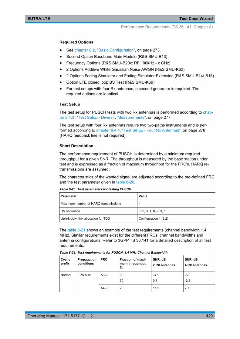
Test Case WizardEUTRA/LTE
329Operating Manual 1171.5177.12 ─ 21
Required Options
● See chapter 8.2, "Basic Configuration", on page 273.● Second Option Baseband Main Module (R&S SMU-B13)● Frequency Options (R&S SMU-B20x: RF 100kHz - x GHz)● 2 Options Additive White Gaussian Noise AWGN (R&S SMU-K62)● 2 Options Fading Simulator and Fading Simulator Extension (R&S SMU-B14/-B15)● Option LTE closed loop BS Test (R&S SMU-K69)● For test setups with four Rx antennas, a second generator is required. The
required options are identical.
Test Setup
The test setup for PUSCH tests with two Rx antennas is performed according to chap-ter 8.4.3, "Test Setup - Diversity Measurements", on page 277.
The test setup with four Rx antennas require two two-paths instruments and is per-formed according to chapter 8.4.4, "Test Setup - Four Rx Antennas", on page 278(HARQ feedback line is not required).
Short Description
The performance requirement of PUSCH is determined by a minimum requiredthroughput for a given SNR. The throughput is measured by the base station undertest and is expressed as a fraction of maximum throughput for the FRC's. HARQ re-transmissions are assumed.
The characteristics of the wanted signal are adjusted according to the pre-defined FRCand the test parameter given in table 8-20.
Table 8-20: Test parameters for testing PUSCH
Parameter Value
Maximum number of HARQ transmissions 4
RV sequence 0, 2, 3, 1, 0, 2, 3, 1
Uplink-downlink allocation for TDD Configuration 1 (2:2)
The table 8-21 shows an example of the test requirements (channel bandwidth 1.4MHz). Similar requirements exist for the different FRCs, channel bandwidths andantenna configurations. Refer to 3GPP TS 36.141 for a detailed description of all testrequirements.
Table 8-21: Test requirements for PUSCH, 1.4 MHz Channel Bandwidth
Cyclicprefix
Propagationconditions
FRC Fraction of maxi-mum throughput,%
SNR, dB
2 RX antennas
SNR, dB
4 RX antennas
Normal EPA 5Hz A3-2 30
70
-3.5
0.7
-6.0
-2.5
A4-3 70 11.2 7.7
Performance Requirements (TS 36.141, Chapter 8)
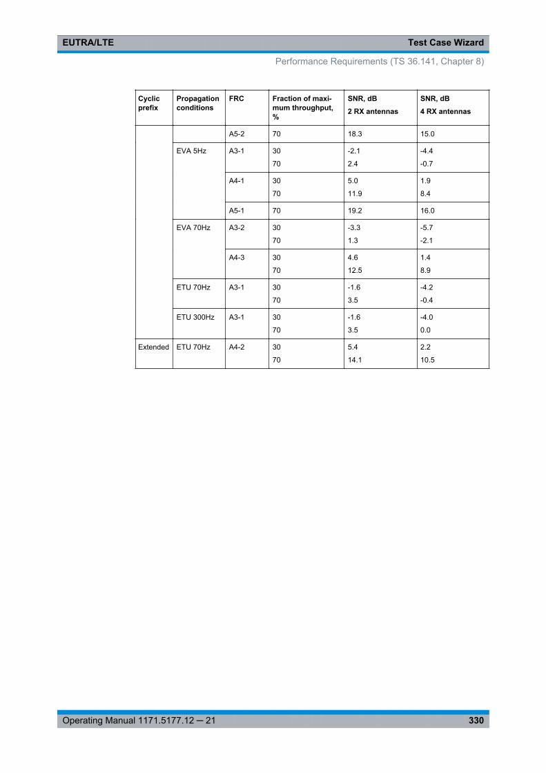
Test Case WizardEUTRA/LTE
330Operating Manual 1171.5177.12 ─ 21
Cyclicprefix
Propagationconditions
FRC Fraction of maxi-mum throughput,%
SNR, dB
2 RX antennas
SNR, dB
4 RX antennas
A5-2 70 18.3 15.0
EVA 5Hz A3-1 30
70
-2.1
2.4
-4.4
-0.7
A4-1 30
70
5.0
11.9
1.9
8.4
A5-1 70 19.2 16.0
EVA 70Hz A3-2 30
70
-3.3
1.3
-5.7
-2.1
A4-3 30
70
4.6
12.5
1.4
8.9
ETU 70Hz A3-1 30
70
-1.6
3.5
-4.2
-0.4
ETU 300Hz A3-1 30
70
-1.6
3.5
-4.0
0.0
Extended ETU 70Hz A4-2 30
70
5.4
14.1
2.2
10.5
Performance Requirements (TS 36.141, Chapter 8)
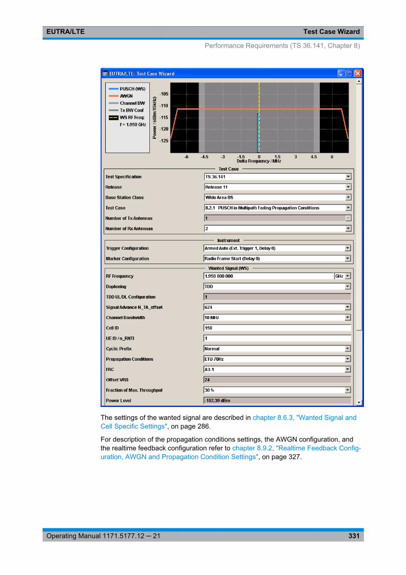
Test Case WizardEUTRA/LTE
331Operating Manual 1171.5177.12 ─ 21
The settings of the wanted signal are described in chapter 8.6.3, "Wanted Signal andCell Specific Settings", on page 286.
For description of the propagation conditions settings, the AWGN configuration, andthe realtime feedback configuration refer to chapter 8.9.2, "Realtime Feedback Config-uration, AWGN and Propagation Condition Settings", on page 327.
Performance Requirements (TS 36.141, Chapter 8)
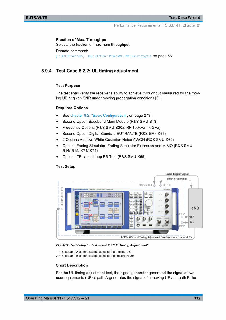
Test Case WizardEUTRA/LTE
332Operating Manual 1171.5177.12 ─ 21
Fraction of Max. ThroughputSelects the fraction of maximum throughput.
Remote command: [: SOURce<hw>]: BB:EUTRa: TCW:WS:FMTHroughput on page 561
8.9.4 Test Case 8.2.2: UL timing adjustment
Test Purpose
The test shall verify the receiver’s ability to achieve throughput measured for the mov-ing UE at given SNR under moving propagation conditions [6].
Required Options
● See chapter 8.2, "Basic Configuration", on page 273.● Second Option Baseband Main Module (R&S SMU-B13)● Frequency Options (R&S SMU-B20x: RF 100kHz - x GHz)● Second Option Digital Standard EUTRA/LTE (R&S SMx-K55)● 2 Options Additive White Gaussian Noise AWGN (R&S SMU-K62)● Options Fading Simulator, Fading Simulator Extension and MIMO (R&S SMU-
B14/-B15/-K71/-K74)● Option LTE closed loop BS Test (R&S SMU-K69)
Test Setup
Fig. 8-12: Test Setup for test case 8.2.2 "UL Timing Adjustment"
1 = Baseband A generates the signal of the moving UE2 = Baseband B generates the signal of the stationary UE
Short Description
For the UL timing adjustment test, the signal generator generated the signal of twouser equipments (UEs); path A generates the signal of a moving UE and path B the
Performance Requirements (TS 36.141, Chapter 8)
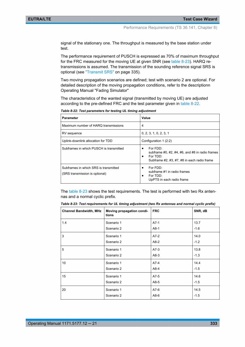
Test Case WizardEUTRA/LTE
333Operating Manual 1171.5177.12 ─ 21
signal of the stationary one. The throughput is measured by the base station undertest.
The performance requirement of PUSCH is expressed as 70% of maximum throughputfor the FRC measured for the moving UE at given SNR (see table 8-23). HARQ re-transmissions is assumed. The transmission of the sounding reference signal SRS isoptional (see "Transmit SRS" on page 335).
Two moving propagation scenarios are defined; test with scenario 2 are optional. Fordetailed description of the moving propagation conditions, refer to the descriptionnOperating Manual "Fading Simulator"
The characteristics of the wanted signal (transmitted by moving UE) are adjustedaccording to the pre-defined FRC and the test parameter given in table 8-22.
Table 8-22: Test parameters for testing UL timing adjustment
Parameter Value
Maximum number of HARQ transmissions 4
RV sequence 0, 2, 3, 1, 0, 2, 3, 1
Uplink-downlink allocation for TDD Configuration 1 (2:2)
Subframes in which PUSCH is transmitted ● For FDD:subframe #0, #2, #4, #6, and #8 in radio frames
● For TDD:Subframe #2, #3, #7, #8 in each radio frame
Subframes in which SRS is transmitted
(SRS transmission is optional)
● For FDD:subframe #1 in radio frames
● For TDD:UpPTS in each radio frame
The table 8-23 shows the test requirements. The test is performed with two Rx anten-nas and a normal cyclic prefix.
Table 8-23: Test requirements for UL timing adjustment (two Rx antennas and normal cyclic prefix)
Channel Bandwidth, MHz Moving propagation condi-tions
FRC SNR, dB
1.4 Scenario 1
Scenario 2
A7-1
A8-1
13.7
-1.6
3 Scenario 1
Scenario 2
A7-2
A8-2
14.0
-1.2
5 Scenario 1
Scenario 2
A7-3
A8-3
13.8
-1.3
10 Scenario 1
Scenario 2
A7-4
A8-4
14.4
-1.5
15 Scenario 1
Scenario 2
A7-5
A8-5
14.6
-1.5
20 Scenario 1
Scenario 2
A7-6
A8-6
14.5
-1.5
Performance Requirements (TS 36.141, Chapter 8)
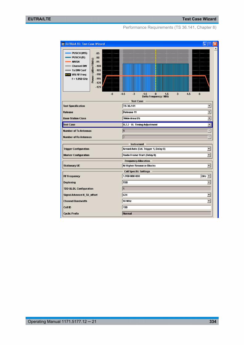
Test Case WizardEUTRA/LTE
334Operating Manual 1171.5177.12 ─ 21
Performance Requirements (TS 36.141, Chapter 8)
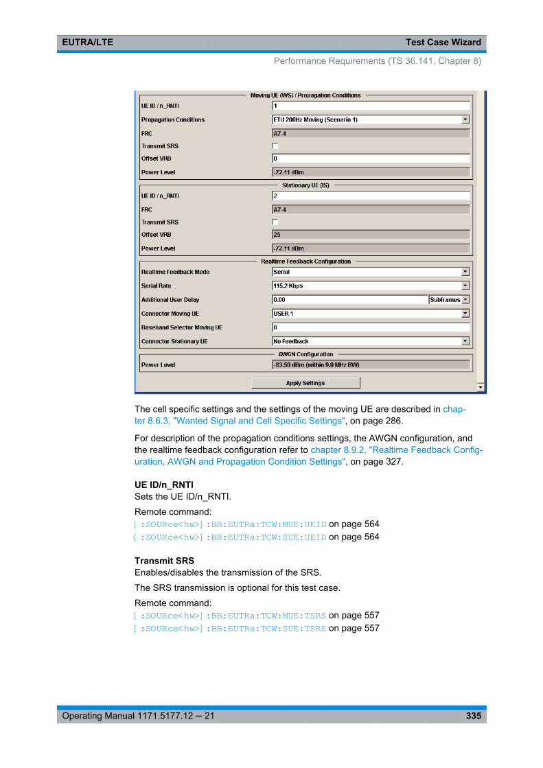
Test Case WizardEUTRA/LTE
335Operating Manual 1171.5177.12 ─ 21
The cell specific settings and the settings of the moving UE are described in chap-ter 8.6.3, "Wanted Signal and Cell Specific Settings", on page 286.
For description of the propagation conditions settings, the AWGN configuration, andthe realtime feedback configuration refer to chapter 8.9.2, "Realtime Feedback Config-uration, AWGN and Propagation Condition Settings", on page 327.
UE ID/n_RNTISets the UE ID/n_RNTI.
Remote command: [:SOURce<hw>]: BB:EUTRa:TCW: MUE:UEID on page 564[: SOURce<hw>]: BB:EUTRa:TCW: SUE:UEID on page 564
Transmit SRSEnables/disables the transmission of the SRS.
The SRS transmission is optional for this test case.
Remote command: [:SOURce<hw>]: BB: EUTRa:TCW: MUE:TSRS on page 557[:SOURce<hw>]: BB: EUTRa: TCW: SUE:TSRS on page 557
Performance Requirements (TS 36.141, Chapter 8)
Test Case WizardEUTRA/LTE
336Operating Manual 1171.5177.12 ─ 21
Offset VRBDisplays the number of RB the allocated RB(s) are shifted with.
Remote command: [:SOURce<hw>]: BB:EUTRa:TCW: MUE:OVRB on page 562[: SOURce<hw>]: BB:EUTRa:TCW: SUE:OVRB on page 562
Connector Moving UE/Stationary UEDetermines the feedback line connector.
Remote command: [:SOURce<hw>]: BB: EUTRa:TCW: RTF:CONMue on page 558[:SOURce<hw>]: BB: EUTRa:TCW: RTF:CONSue on page 558
Baseband Selector Moving UE("Serial" and "Serial 3x8" mode only)
This parameter is required for multiplexing serial commands for different basebandunits to one feedback line. If the selector n is configured in the GUI for a specific base-band unit, the baseband unit will listen only to serial commands containing the selectorn.
Remote command: [:SOURce<hw>]: BB:EUTRa:TCW: RTF:BBSMue on page 557[: SOURce<hw>]: BB:EUTRa:TCW: RTF:BBSSue on page 557
8.9.5 Test Case 8.2.3: HARQ-ACK multiplexed on PUSCH
Test Purpose
The test shall verify the receiver’s ability to detect HARQ-ACK information multiplexedon PUSCH under multipath fading propagation conditions for a given SNR [6].
Required Options
● See chapter 8.2, "Basic Configuration", on page 273.● Second Option Baseband Main Module (R&S SMU-B13)● Frequency Options (R&S SMU-B20x: RF 100kHz - x GHz)● 2 Options Additive White Gaussian Noise AWGN (R&S SMU-K62)● 2 Options Fading Simulator and Fading Simulator Extension (R&S SMU-B14/-B15)
Test Setup
See chapter 8.4.3, "Test Setup - Diversity Measurements", on page 277 (HARQ feed-back line is not required).
Short Description
The performance requirement of HARQ-ACK multiplexed on PUSCH is determined bythe two parameters: probability of false detection of the ACK and the probability ofdetection of ACK. The performance is measured by the required SNR at probability of
Performance Requirements (TS 36.141, Chapter 8)
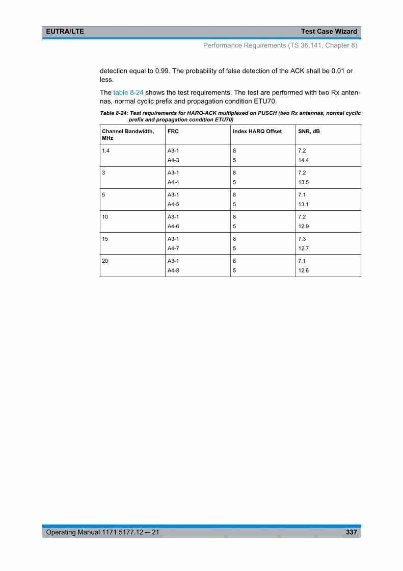
Test Case WizardEUTRA/LTE
337Operating Manual 1171.5177.12 ─ 21
detection equal to 0.99. The probability of false detection of the ACK shall be 0.01 orless.
The table 8-24 shows the test requirements. The test are performed with two Rx anten-nas, normal cyclic prefix and propagation condition ETU70.
Table 8-24: Test requirements for HARQ-ACK multiplexed on PUSCH (two Rx antennas, normal cyclicprefix and propagation condition ETU70)
Channel Bandwidth,MHz
FRC Index HARQ Offset SNR, dB
1.4 A3-1
A4-3
8
5
7.2
14.4
3 A3-1
A4-4
8
5
7.2
13.5
5 A3-1
A4-5
8
5
7.1
13.1
10 A3-1
A4-6
8
5
7.2
12.9
15 A3-1
A4-7
8
5
7.3
12.7
20 A3-1
A4-8
8
5
7.1
12.6
Performance Requirements (TS 36.141, Chapter 8)

Test Case WizardEUTRA/LTE
338Operating Manual 1171.5177.12 ─ 21
The settings of the wanted signal are described in chapter 8.6.3, "Wanted Signal andCell Specific Settings", on page 286.
For description of the propagation conditions settings and the AWGN configuration,refer to "Propagation Conditions" on page 328 and "AWGN Configuration"on page 328.
Performance Requirements (TS 36.141, Chapter 8)
Test Case WizardEUTRA/LTE
339Operating Manual 1171.5177.12 ─ 21
8.9.6 Test Case 8.2.4: High Speed Train conditions
Test Purpose
The test shall verify the receiver’s ability to achieve throughput under High Speed Trainconditions for a given SNR [6].
Required Options
The following options are sufficient for tests with one Rx Antenna:● See chapter 8.2, "Basic Configuration", on page 273.● Option Additive White Gaussian Noise AWGN (R&S SMU-K62)● Option Fading Simulator and Fading Simulator Extension (R&S SMU-B14/-K71)● Option LTE closed loop BS Test (R&S SMU-K69)
For tests with more than one Rx Antenna, the following options are required addition-ally:● Second Option Additive White Gaussian Noise AWGN (R&S SMU-K62)● Second Baseband Main Module (R&S SMU-B13)● Option Fading Simulator Extension (R&S SMU-B15)
Test Setup
See chapter 8.4.3, "Test Setup - Diversity Measurements", on page 277 and chap-ter 8.4.1, "Standard Test Setup - One Path", on page 276 (additionally, a feedback lineis required).
Short Description
The performance requirement is determined by a minimum throughput for a givenSNR. The requirement throughput is expressed as 30% and 70% of the maximumthroughput for the FRC (see table 8-25). HARQ retransmission is assumed. The testsare performed with one or two Rx antennas, normal cyclic prefix and propagation con-dition HST.
The test is optional.
The characteristics of the wanted signal are adjusted according to the pre-defined FRCand the test parameter given in table 8-26.
Table 8-25: Test parameters for High Speed Train conditions
Parameter Value
Maximum number of HARQ transmissions 4
RV sequence 0, 2, 3, 1, 0, 2, 3, 1
Uplink-downlink allocation for TDD Configuration 1 (2:2)
*) The configuration of PUCCH (format 2) is optional;The SNR values per antenna shall be set to [-4.5 dBand -1.5 dB] for Scenario 1 and 3, respectively.
Performance Requirements (TS 36.141, Chapter 8)
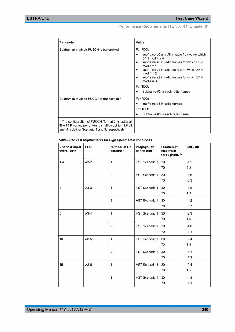
Test Case WizardEUTRA/LTE
340Operating Manual 1171.5177.12 ─ 21
Parameter Value
Subframes in which PUSCH is transmitted For FDD:● subframe #0 and #8 in radio frames for which
SFN mod 4 = 0● subframe #6 in radio frames for which SFN
mod 4 = 1● subframe #4 in radio frames for which SFN
mod 4 = 2● subframe #2 in radio frames for which SFN
mod 4 = 3
For TDD:● Subframe #2 in each radio frames
Subframes in which PUCCH is transmitted * For FDD:● subframe #5 in radio frames
For TDD:● Subframe #3 in each radio frame
*) The configuration of PUCCH (format 2) is optional;The SNR values per antenna shall be set to [-4.5 dBand -1.5 dB] for Scenario 1 and 3, respectively.
Table 8-26: Test requirements for High Speed Train conditions
Channel Band-width, MHz
FRC Number of RXantennas
Propagationconditions
Fraction ofmaximumthroughput, %
SNR, dB
1.4 A3-2 1 HST Scenario 3 30
70
-1.2
2.2
2 HST Scenario 1 30
70
-3.6
-0.3
3 A3-3 1 HST Scenario 3 30
70
-1.8
1.9
2 HST Scenario 1 30
70
-4.2
-0.7
5 A3-4 1 HST Scenario 3 30
70
-2.3
1.6
2 HST Scenario 1 30
70
-4.8
-1.1
10 A3-5 1 HST Scenario 3 30
70
-2.4
1.5
2 HST Scenario 1 30
70
-5.1
-1.2
15 A3-6 1 HST Scenario 3 30
70
-2.4
1.5
2 HST Scenario 1 30
70
-4.9
-1.1
Performance Requirements (TS 36.141, Chapter 8)
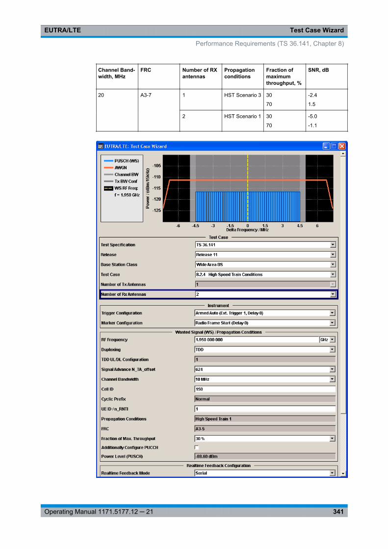
Test Case WizardEUTRA/LTE
341Operating Manual 1171.5177.12 ─ 21
Channel Band-width, MHz
FRC Number of RXantennas
Propagationconditions
Fraction ofmaximumthroughput, %
SNR, dB
20 A3-7 1 HST Scenario 3 30
70
-2.4
1.5
2 HST Scenario 1 30
70
-5.0
-1.1
Performance Requirements (TS 36.141, Chapter 8)
Test Case WizardEUTRA/LTE
342Operating Manual 1171.5177.12 ─ 21
The settings of the wanted signal are described in chapter 8.6.3, "Wanted Signal andCell Specific Settings", on page 286.
For description of the propagation conditions settings, the AWGN configuration, andthe realtime feedback configuration refer to chapter 8.9.2, "Realtime Feedback Config-uration, AWGN and Propagation Condition Settings", on page 327.
Additionally Configure PUCCHEnables the optional transmission of PUCCH format 2.
The settings are configured according to table 8-26; the PUCCH Power Level is calcu-lated automatically.
Remote command: [:SOURce<hw>]: BB:EUTRa: TCW:WS: ACPucch on page 559
Power Level (PUSCH)Displays the resulting PUSCH power level.
Remote command: [:SOURce<hw>]: BB:EUTRa: TCW:WS:PLPS? on page 563
PUCCH Power Level(enabled for activated optional transmission of PUCCH format 2)
Displays the resulting PUCCH power level.
Remote command: [:SOURce<hw>]: BB: EUTRa:TCW: WS:PLPC? on page 563
8.9.7 Test Case 8.3.1: ACK missed detection for single user PUCCH for-mat 1a
Test Purpose
The test shall verify the receiver’s ability to detect ACK under multipath fading propa-gation conditions for a given SNR [6].
Required Options
● See chapter 8.2, "Basic Configuration", on page 273.● Second Option Baseband Main Module (R&S SMU-B13)● Frequency Options (R&S SMU-B20x: RF 100kHz - x GHz)● 2 Options Additive White Gaussian Noise AWGN (R&S SMU-K62)● 2 Options Fading Simulator and Fading Simulator Extension (R&S SMU-B14/-B15)● For test setups with four Rx antennas, a second generator is required. The
required options are identical.
Performance Requirements (TS 36.141, Chapter 8)
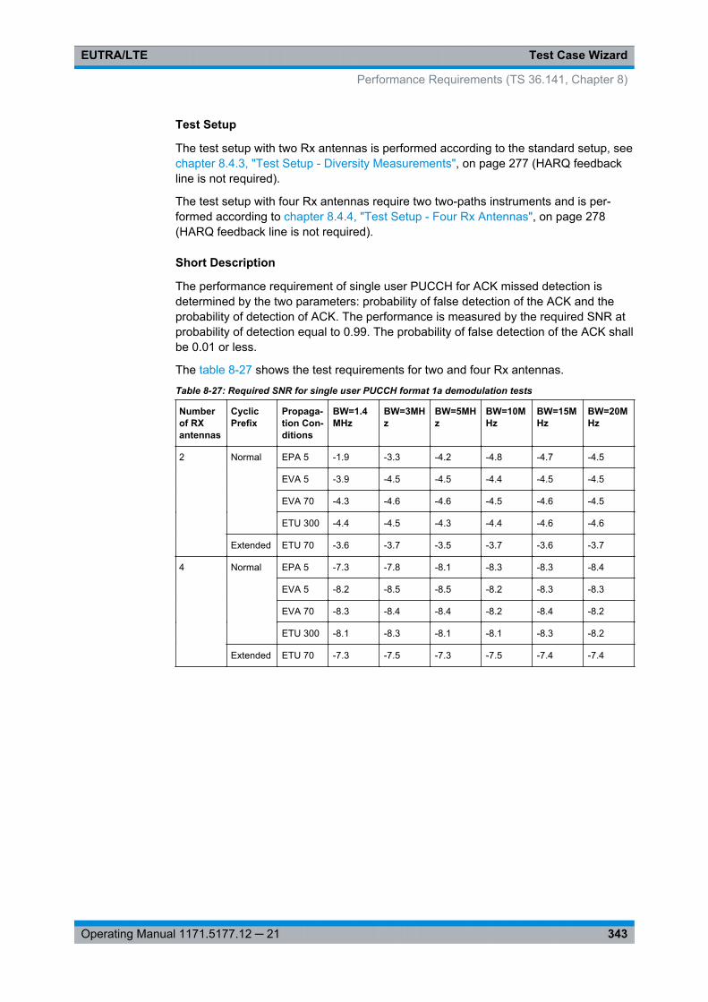
Test Case WizardEUTRA/LTE
343Operating Manual 1171.5177.12 ─ 21
Test Setup
The test setup with two Rx antennas is performed according to the standard setup, seechapter 8.4.3, "Test Setup - Diversity Measurements", on page 277 (HARQ feedbackline is not required).
The test setup with four Rx antennas require two two-paths instruments and is per-formed according to chapter 8.4.4, "Test Setup - Four Rx Antennas", on page 278(HARQ feedback line is not required).
Short Description
The performance requirement of single user PUCCH for ACK missed detection isdetermined by the two parameters: probability of false detection of the ACK and theprobability of detection of ACK. The performance is measured by the required SNR atprobability of detection equal to 0.99. The probability of false detection of the ACK shallbe 0.01 or less.
The table 8-27 shows the test requirements for two and four Rx antennas.
Table 8-27: Required SNR for single user PUCCH format 1a demodulation tests
Numberof RXantennas
CyclicPrefix
Propaga-tion Con-ditions
BW=1.4MHz
BW=3MHz
BW=5MHz
BW=10MHz
BW=15MHz
BW=20MHz
2 Normal EPA 5 -1.9 -3.3 -4.2 -4.8 -4.7 -4.5
EVA 5 -3.9 -4.5 -4.5 -4.4 -4.5 -4.5
EVA 70 -4.3 -4.6 -4.6 -4.5 -4.6 -4.5
ETU 300 -4.4 -4.5 -4.3 -4.4 -4.6 -4.6
Extended ETU 70 -3.6 -3.7 -3.5 -3.7 -3.6 -3.7
4 Normal EPA 5 -7.3 -7.8 -8.1 -8.3 -8.3 -8.4
EVA 5 -8.2 -8.5 -8.5 -8.2 -8.3 -8.3
EVA 70 -8.3 -8.4 -8.4 -8.2 -8.4 -8.2
ETU 300 -8.1 -8.3 -8.1 -8.1 -8.3 -8.2
Extended ETU 70 -7.3 -7.5 -7.3 -7.5 -7.4 -7.4
Performance Requirements (TS 36.141, Chapter 8)
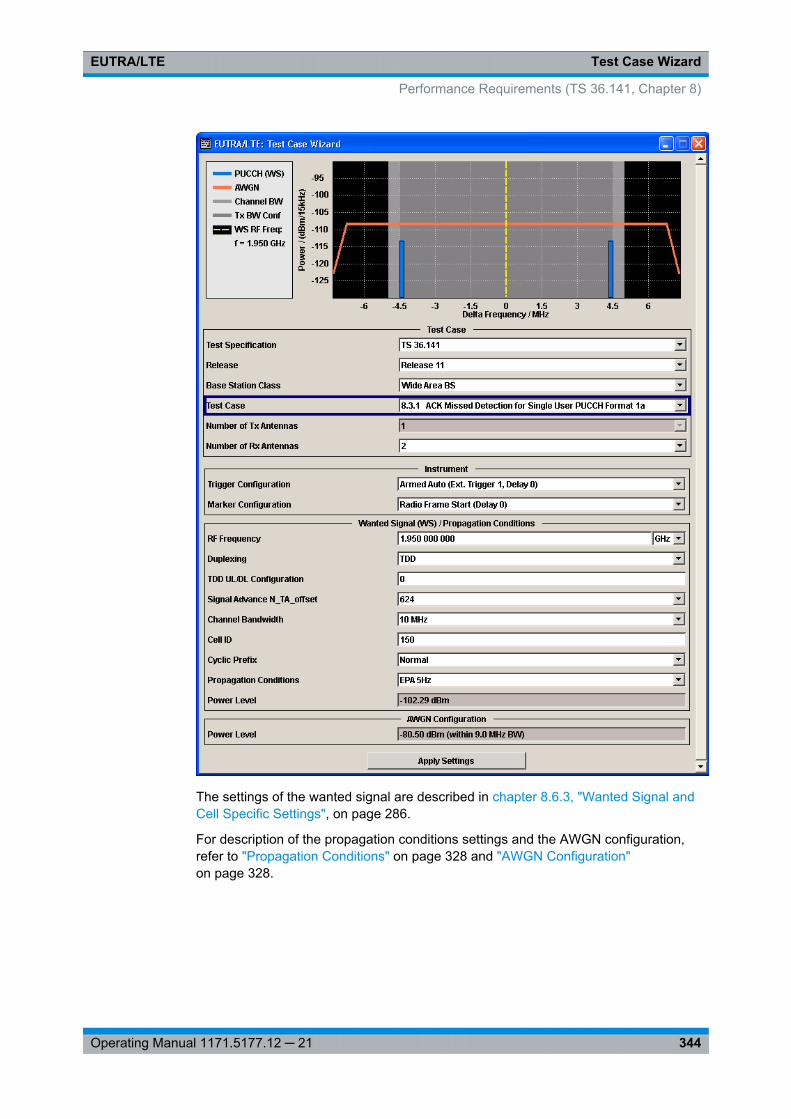
Test Case WizardEUTRA/LTE
344Operating Manual 1171.5177.12 ─ 21
The settings of the wanted signal are described in chapter 8.6.3, "Wanted Signal andCell Specific Settings", on page 286.
For description of the propagation conditions settings and the AWGN configuration,refer to "Propagation Conditions" on page 328 and "AWGN Configuration"on page 328.
Performance Requirements (TS 36.141, Chapter 8)
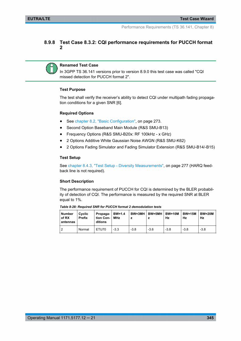
Test Case WizardEUTRA/LTE
345Operating Manual 1171.5177.12 ─ 21
8.9.8 Test Case 8.3.2: CQI performance requirements for PUCCH format2
Renamed Test CaseIn 3GPP TS 36.141 versions prior to version 8.9.0 this test case was called "CQImissed detection for PUCCH format 2".
Test Purpose
The test shall verify the receiver’s ability to detect CQI under multipath fading propaga-tion conditions for a given SNR [6].
Required Options
● See chapter 8.2, "Basic Configuration", on page 273.● Second Option Baseband Main Module (R&S SMU-B13)● Frequency Options (R&S SMU-B20x: RF 100kHz - x GHz)● 2 Options Additive White Gaussian Noise AWGN (R&S SMU-K62)● 2 Options Fading Simulator and Fading Simulator Extension (R&S SMU-B14/-B15)
Test Setup
See chapter 8.4.3, "Test Setup - Diversity Measurements", on page 277 (HARQ feed-back line is not required).
Short Description
The performance requirement of PUCCH for CQI is determined by the BLER probabil-ity of detection of CQI. The performance is measured by the required SNR at BLERequal to 1%.
Table 8-28: Required SNR for PUCCH format 2 demodulation tests
Numberof RXantennas
CyclicPrefix
Propaga-tion Con-ditions
BW=1.4MHz
BW=3MHz
BW=5MHz
BW=10MHz
BW=15MHz
BW=20MHz
2 Normal ETU70 -3.3 -3.8 -3.6 -3.8 -3.8 -3.8
Performance Requirements (TS 36.141, Chapter 8)
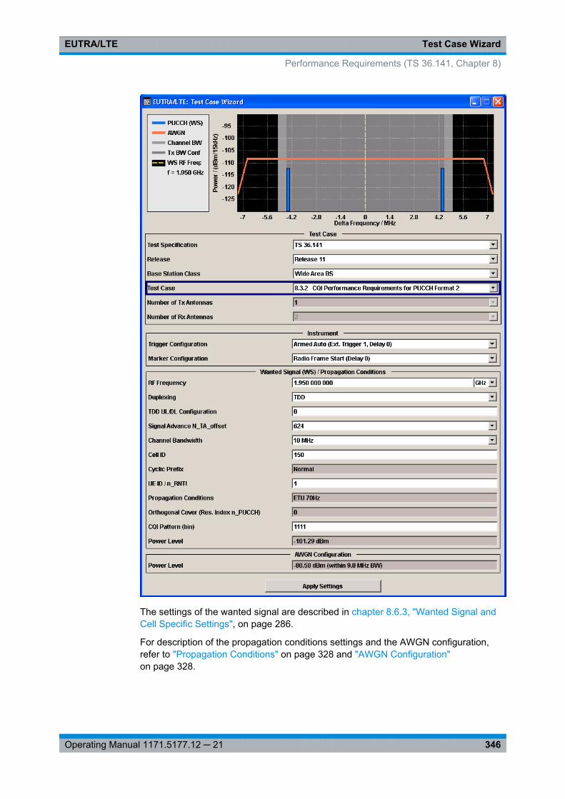
Test Case WizardEUTRA/LTE
346Operating Manual 1171.5177.12 ─ 21
The settings of the wanted signal are described in chapter 8.6.3, "Wanted Signal andCell Specific Settings", on page 286.
For description of the propagation conditions settings and the AWGN configuration,refer to "Propagation Conditions" on page 328 and "AWGN Configuration"on page 328.
Performance Requirements (TS 36.141, Chapter 8)
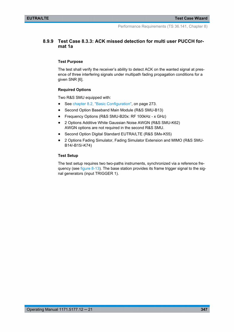
Test Case WizardEUTRA/LTE
347Operating Manual 1171.5177.12 ─ 21
8.9.9 Test Case 8.3.3: ACK missed detection for multi user PUCCH for-mat 1a
Test Purpose
The test shall verify the receiver’s ability to detect ACK on the wanted signal at pres-ence of three interfering signals under multipath fading propagation conditions for agiven SNR [6].
Required Options
Two R&S SMU equipped with:● See chapter 8.2, "Basic Configuration", on page 273.● Second Option Baseband Main Module (R&S SMU-B13)● Frequency Options (R&S SMU-B20x: RF 100kHz - x GHz)● 2 Options Additive White Gaussian Noise AWGN (R&S SMU-K62)
AWGN options are not required in the second R&S SMU.● Second Option Digital Standard EUTRA/LTE (R&S SMx-K55)● 2 Options Fading Simulator, Fading Simulator Extension and MIMO (R&S SMU-
B14/-B15/-K74)
Test Setup
The test setup requires two two-paths instruments, synchronized via a reference fre-quency (see figure 8-13). The base station provides its frame trigger signal to the sig-nal generators (input TRIGGER 1).
Performance Requirements (TS 36.141, Chapter 8)
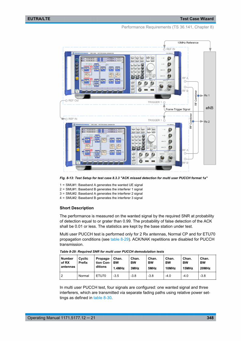
Test Case WizardEUTRA/LTE
348Operating Manual 1171.5177.12 ─ 21
Fig. 8-13: Test Setup for test case 8.3.3 "ACK missed detection for multi user PUCCH format 1a"
1 = SMU#1: Baseband A generates the wanted UE signal2 = SMU#1: Baseband B generates the interferer 1 signal3 = SMU#2: Baseband A generates the interferer 2 signal4 = SMU#2: Baseband B generates the interferer 3 signal
Short Description
The performance is measured on the wanted signal by the required SNR at probabilityof detection equal to or grater than 0.99. The probability of false detection of the ACKshall be 0.01 or less. The statistics are kept by the base station under test.
Multi user PUCCH test is performed only for 2 Rx antennas, Normal CP and for ETU70propagation conditions (see table 8-29). ACK/NAK repetitions are disabled for PUCCHtransmission.
Table 8-29: Required SNR for multi user PUCCH demodulation tests
Numberof RXantennas
CyclicPrefix
Propaga-tion Con-ditions
Chan.BW
1.4MHz
Chan.BW
3MHz
Chan.BW
5MHz
Chan.BW
10MHz
Chan.BW
15MHz
Chan.BW
20MHz
2 Normal ETU70 -3.5 -3.8 -3.8 -4.0 -4.0 -3.8
In multi user PUCCH test, four signals are configured: one wanted signal and threeinterferers, which are transmitted via separate fading paths using relative power set-tings as defined in table 8-30.
Performance Requirements (TS 36.141, Chapter 8)
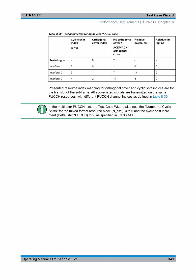
Test Case WizardEUTRA/LTE
349Operating Manual 1171.5177.12 ─ 21
Table 8-30: Test parameters for multi user PUCCH case
Cyclic shiftindex
(δ =0)
Orthogonalcover index
RS orthogonalcover /
ACK/NACKorthogonalcover
Relativepower, dB
Relative tim-ing, ns
Tested signal 4 0 2 - -
Interferer 1 2 0 1 0 0
Interferer 2 3 1 7 -3 0
Interferer 3 4 2 14 3 0
Presented resource index mapping for orthogonal cover and cyclic shift indices are forthe first slot of the subframe. All above listed signals are transmitted on the samePUCCH resources, with different PUCCH channel indices as defined in table 8-30.
In the multi user PUCCH test, the Test Case Wizard also sets the "Number of CyclicShifts" for the mixed format resource block (N_cs^(1)) to 0 and the cyclic shift incre-ment (Delta_shift^PUCCH) to 2, as specified in TS 36.141.
Performance Requirements (TS 36.141, Chapter 8)
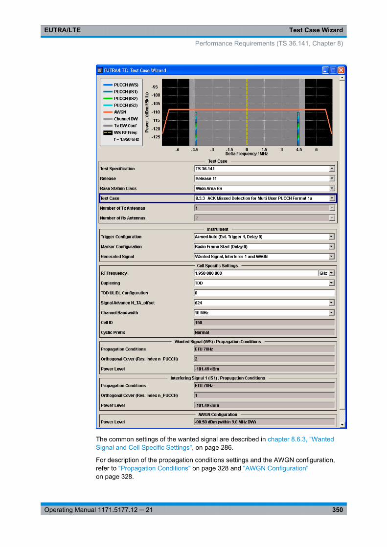
Test Case WizardEUTRA/LTE
350Operating Manual 1171.5177.12 ─ 21
The common settings of the wanted signal are described in chapter 8.6.3, "WantedSignal and Cell Specific Settings", on page 286.
For description of the propagation conditions settings and the AWGN configuration,refer to "Propagation Conditions" on page 328 and "AWGN Configuration"on page 328.
Performance Requirements (TS 36.141, Chapter 8)
Test Case WizardEUTRA/LTE
351Operating Manual 1171.5177.12 ─ 21
In the instrument, the power level of the interferer 3 is used as a reference, i.e. thepower level of the wanted signal and the interferer 1 is 3 dB lower and the power levelof the inerferer 2 is 6 dB lower than the reference.
Generated SignalDetermines which signals are generated by the instrument. The first R&S SMU shouldgenerate the "Wanted Signal, Interfer 1 and AWGN" signal and the second R&S SMU,the signal of "Interferers 2 and 3".
Remote command: [:SOURce<hw>]: BB: EUTRa:TCW: GS:GENSignals on page 550
Propagation ConditionsDisplays the porpagation conditions of the interfering signal.
Remote command: [: SOURce<hw>]: BB:EUTRa: TCW:IS:PRCOndition? on page 563[: SOURce<hw>]: BB:EUTRa: TCW:IS2:PRCOndition? on page 563[: SOURce<hw>]: BB:EUTRa: TCW:IS3:PRCOndition? on page 563
Orthogonal Cover (Res. Index n_PUCCH) / Orthogonal Cover (Res. Indexn_PUCCH) Port 0/1Displays the used resource index n_PUCCH.
The value is set automaticaly according to the RS orthogonal cover in table 8-30.
Remote command: [: SOURce<hw>]: BB:EUTRa: TCW:WS:ORTCover? on page 562[: SOURce<hw>]: BB:EUTRa: TCW:IS:ORTCover? on page 562[: SOURce<hw>]: BB:EUTRa: TCW:IS2:ORTCover? on page 562[: SOURce<hw>]: BB:EUTRa: TCW:IS3:ORTCover? on page 562[: SOURce<hw>]: BB:EUTRa: TCW:WS:ORTCover[: PORT<ch0>]? on page 562
Interferer TypeDisplays the type of the interfering signal.
Remote command: [:SOURce<hw>]: BB: EUTRa:TCW: IS2:IFTYpe? on page 554
RF FrequencyDisplays the center frequency of interfering signal.
Remote command: [:SOURce<hw>]: BB: EUTRa:TCW: IS2:RFFRequency? on page 555
Power LevelDisplays the power level of the interfering signals.
Remote command: [:SOURce<hw>]: BB: EUTRa:TCW: IS2:PLEVel? on page 555[:SOURce<hw>]: BB: EUTRa:TCW: IS3:PLEVel? on page 555
Performance Requirements (TS 36.141, Chapter 8)
Test Case WizardEUTRA/LTE
352Operating Manual 1171.5177.12 ─ 21
8.9.10 Test Case 8.3.4: ACK missed detection for PUCCH format 1b, chan-nel selection
Test Purpose
The test shall verify the receiver’s ability to detect ACK bits under multipath fadingpropagation conditions for a given SNR [6].
Required Options
● See chapter 8.2, "Basic Configuration", on page 273.● Second Option Baseband Main Module (R&S SMU-B13)● Frequency Options (R&S SMU-B20x: RF 100kHz - x GHz)● 2 Options Additive White Gaussian Noise AWGN (R&S SMU-K62)● Second Option Digital Standard EUTRA/LTE (R&S SMx-K55)● 2 Options Fading Simulator, Fading Simulator Extension and MIMO (R&S SMU-
B14/-B15/-K74)
Test Setup
The test setup with two Rx antennas is performed according to the standard setup, seechapter 8.4.3, "Test Setup - Diversity Measurements", on page 277 (HARQ feedbackline is not required).
The test setup with four Rx antennas requires additional instruments, see chap-ter 8.4.4, "Test Setup - Four Rx Antennas", on page 278 (HARQ feedback line is notrequired).
This test case is applicable to all BS.
The instrument generates a signal with 4 encoded ACK/NACK bits per subframe(AAAA).
Short Description
The performance requirement of PUCCH format 1b with Channel Selection for ACKmissed detection is determined by:● the probability of false detection of the ACK● the probability of detection of ACK
The performance is measured on the wanted signal by the required SNR at probabilityof detection equal to 0.99. The fraction of false detection of the ACK shall be 0.01 orless. The statistics are kept by the base station under test.
Performance Requirements (TS 36.141, Chapter 8)
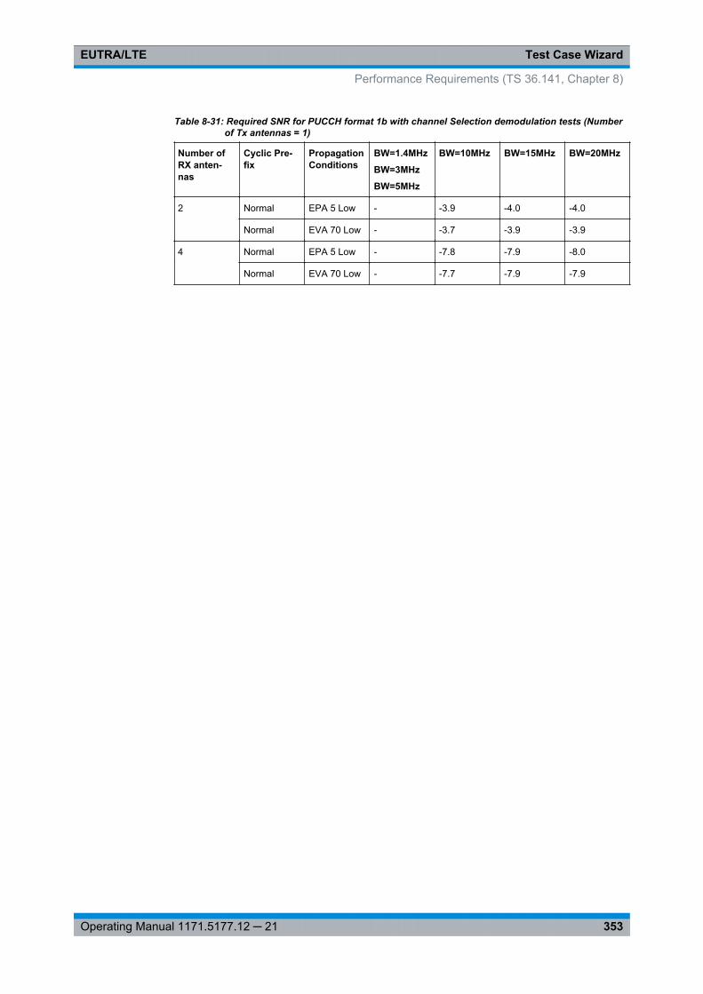
Test Case WizardEUTRA/LTE
353Operating Manual 1171.5177.12 ─ 21
Table 8-31: Required SNR for PUCCH format 1b with channel Selection demodulation tests (Numberof Tx antennas = 1)
Number ofRX anten-nas
Cyclic Pre-fix
PropagationConditions
BW=1.4MHz
BW=3MHz
BW=5MHz
BW=10MHz BW=15MHz BW=20MHz
2 Normal EPA 5 Low - -3.9 -4.0 -4.0
Normal EVA 70 Low - -3.7 -3.9 -3.9
4 Normal EPA 5 Low - -7.8 -7.9 -8.0
Normal EVA 70 Low - -7.7 -7.9 -7.9
Performance Requirements (TS 36.141, Chapter 8)
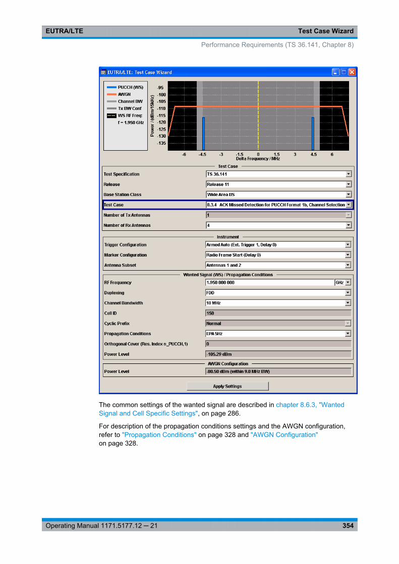
Test Case WizardEUTRA/LTE
354Operating Manual 1171.5177.12 ─ 21
The common settings of the wanted signal are described in chapter 8.6.3, "WantedSignal and Cell Specific Settings", on page 286.
For description of the propagation conditions settings and the AWGN configuration,refer to "Propagation Conditions" on page 328 and "AWGN Configuration"on page 328.
Performance Requirements (TS 36.141, Chapter 8)
Test Case WizardEUTRA/LTE
355Operating Manual 1171.5177.12 ─ 21
8.9.11 Test Case 8.3.5: ACK missed detection for PUCCH format 3
Test Purpose
The test shall verify the receiver’s ability to detect ACK bits under codeword's fromapplicable codebook being randomly selected, multipath fading propagation conditionsfor a given SNR [6].
Required Options
● See chapter 8.2, "Basic Configuration", on page 273.● Second Option Baseband Main Module (R&S SMU-B13)● Frequency Options (R&S SMU-B20x: RF 100kHz - x GHz)● 2 Options Additive White Gaussian Noise AWGN (R&S SMU-K62)● Second Option Digital Standard EUTRA/LTE (R&S SMx-K55)● 2 Options Fading Simulator, Fading Simulator Extension and MIMO (R&S SMU-
B14/-B15/-K74)
Test Setup
The test setup with two Rx antennas is performed according to the standard setup, seechapter 8.4.3, "Test Setup - Diversity Measurements", on page 277 (HARQ feedbackline is not required).
The test setup with four Rx antennas requires additional instruments, see chap-ter 8.4.4, "Test Setup - Four Rx Antennas", on page 278 (HARQ feedback line is notrequired).
This test case is applicable to all BS.
The instrument generates the required signal with 4 or 16 encoded ACK/NACK bits(AN bits) per subframe, as defined with the parameter Number of ACK/NACK bits.
ACK/NACK repetition is disabled for PUCCH transmission. Random codewords selec-tion is assumed.
Short Description
The performance requirement of PUCCH format 3 for ACK missed detection is deter-mined by:● the probability of false detection of the ACK● the probability of detection of ACK
The performance is measured on the wanted signal by the required SNR at probabilityof detection equal to 0.99. The fraction of false detection of the ACK shall be 0.01 orless. The statistics are kept by the base station under test.
Performance Requirements (TS 36.141, Chapter 8)
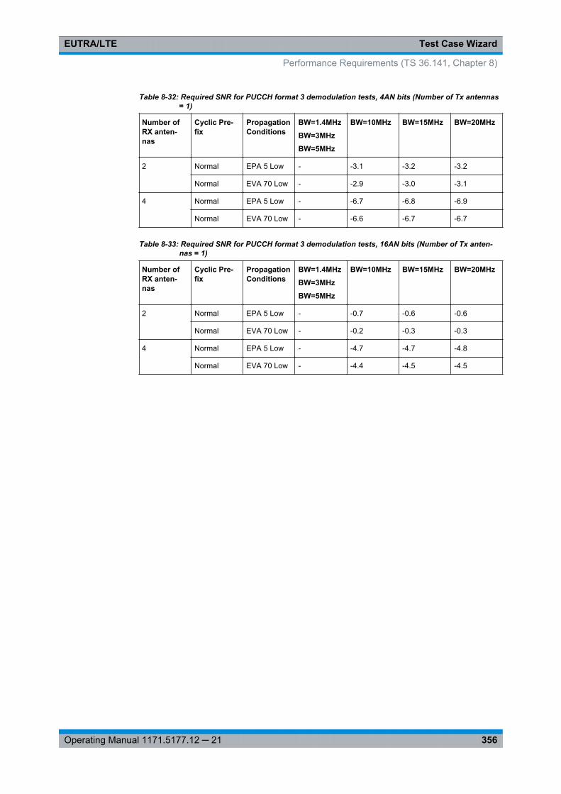
Test Case WizardEUTRA/LTE
356Operating Manual 1171.5177.12 ─ 21
Table 8-32: Required SNR for PUCCH format 3 demodulation tests, 4AN bits (Number of Tx antennas= 1)
Number ofRX anten-nas
Cyclic Pre-fix
PropagationConditions
BW=1.4MHz
BW=3MHz
BW=5MHz
BW=10MHz BW=15MHz BW=20MHz
2 Normal EPA 5 Low - -3.1 -3.2 -3.2
Normal EVA 70 Low - -2.9 -3.0 -3.1
4 Normal EPA 5 Low - -6.7 -6.8 -6.9
Normal EVA 70 Low - -6.6 -6.7 -6.7
Table 8-33: Required SNR for PUCCH format 3 demodulation tests, 16AN bits (Number of Tx anten-nas = 1)
Number ofRX anten-nas
Cyclic Pre-fix
PropagationConditions
BW=1.4MHz
BW=3MHz
BW=5MHz
BW=10MHz BW=15MHz BW=20MHz
2 Normal EPA 5 Low - -0.7 -0.6 -0.6
Normal EVA 70 Low - -0.2 -0.3 -0.3
4 Normal EPA 5 Low - -4.7 -4.7 -4.8
Normal EVA 70 Low - -4.4 -4.5 -4.5
Performance Requirements (TS 36.141, Chapter 8)
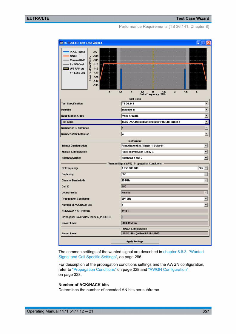
Test Case WizardEUTRA/LTE
357Operating Manual 1171.5177.12 ─ 21
The common settings of the wanted signal are described in chapter 8.6.3, "WantedSignal and Cell Specific Settings", on page 286.
For description of the propagation conditions settings and the AWGN configuration,refer to "Propagation Conditions" on page 328 and "AWGN Configuration"on page 328.
Number of ACK/NACK bitsDetermines the number of encoded AN bits per subframe.
Performance Requirements (TS 36.141, Chapter 8)
Test Case WizardEUTRA/LTE
358Operating Manual 1171.5177.12 ─ 21
"4" Applicable for TDD and FDD (see Duplexing)
"16" Applicable for TDD
Remote command: [:SOURce<hw>]: BB: EUTRa:TCW: WS:ANBits on page 559
ACK/NACK + SR PatternDisplays the used ACK/NACK + SR pattern, depending on the selected Number ofACK/NACK bits.
Remote command: [:SOURce<hw>]: BB: EUTRa:TCW: WS:ANPattern? on page 559
8.9.12 Test Case 8.3.6: NACK to ACK detection for PUCCH format 3
Test Purpose
The test shall verify the receiver’s ability not to falsely detect NACK bits, transmitted incodeword randomly selected from applicable codebook, as ACK bits under multipathfading propagation conditions for a given SNR [6].
Required Options
● See chapter 8.2, "Basic Configuration", on page 273.● Second Option Baseband Main Module (R&S SMU-B13)● Frequency Options (R&S SMU-B20x: RF 100kHz - x GHz)● 2 Options Additive White Gaussian Noise AWGN (R&S SMU-K62)● Second Option Digital Standard EUTRA/LTE (R&S SMx-K55)● 2 Options Fading Simulator, Fading Simulator Extension and MIMO (R&S SMU-
B14/-B15/-K74)
Test Setup
The test setup with two Rx antennas is performed according to the standard setup, seechapter 8.4.3, "Test Setup - Diversity Measurements", on page 277 (HARQ feedbackline is not required).
The test setup with four Rx antennas requires additional instruments, see chap-ter 8.4.4, "Test Setup - Four Rx Antennas", on page 278 (HARQ feedback line is notrequired).
This test case is applicable to all BS.
The instrument generates the required signal with 16 encoded ACK/NACK bits (ANbits) per subframe.
ACK/NACK repetition is disabled for PUCCH transmission. Random codewords selec-tion is assumed.
Performance Requirements (TS 36.141, Chapter 8)
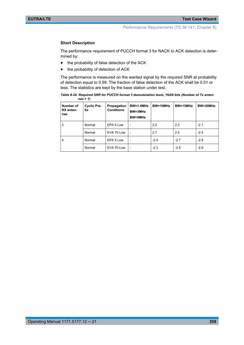
Test Case WizardEUTRA/LTE
359Operating Manual 1171.5177.12 ─ 21
Short Description
The performance requirement of PUCCH format 3 for NACK to ACK detection is deter-mined by:● the probability of false detection of the ACK● the probability of detection of ACK
The performance is measured on the wanted signal by the required SNR at probabilityof detection equal to 0.99. The fraction of false detection of the ACK shall be 0.01 orless. The statistics are kept by the base station under test.
Table 8-34: Required SNR for PUCCH format 3 demodulation tests, 16AN bits (Number of Tx anten-nas = 1)
Number ofRX anten-nas
Cyclic Pre-fix
PropagationConditions
BW=1.4MHz
BW=3MHz
BW=5MHz
BW=10MHz BW=15MHz BW=20MHz
2 Normal EPA 5 Low - 2.0 2.2 -2.1
Normal EVA 70 Low - 2.7 2.5 -2.5
4 Normal EPA 5 Low - -2.5 -2.7 -2.9
Normal EVA 70 Low - -2.3 -2.5 -2.6
Performance Requirements (TS 36.141, Chapter 8)

Test Case WizardEUTRA/LTE
360Operating Manual 1171.5177.12 ─ 21
The common settings of the wanted signal are described in chapter 8.6.3, "WantedSignal and Cell Specific Settings", on page 286.
Performance Requirements (TS 36.141, Chapter 8)

Test Case WizardEUTRA/LTE
361Operating Manual 1171.5177.12 ─ 21
For description of the propagation conditions settings and the AWGN configuration,refer to "Propagation Conditions" on page 328 and "AWGN Configuration"on page 328.
8.9.13 Test Case 8.3.9: CQI Performance for PUCCH format 2 with DTXdetection
Test Purpose
The test shall verify the receiver’s ability to detect CQI under multipath fading propaga-tion conditions for a given SNR [6].
Required Options
● See chapter 8.2, "Basic Configuration", on page 273.● Second Option Baseband Main Module (R&S SMU-B13)● Frequency Options (R&S SMU-B20x: RF 100kHz - x GHz)● 2 Options Additive White Gaussian Noise AWGN (R&S SMU-K62)● Second Option Digital Standard EUTRA/LTE (R&S SMx-K55)● 2 Options Fading Simulator, Fading Simulator Extension and MIMO (R&S SMU-
B14/-B15/-K74)
Test Setup
The test setup is performed according to the standard setup, see chapter 8.4.3, "TestSetup - Diversity Measurements", on page 277 (HARQ feedback line is not required).
This test case is optional and applicable to a BS supporting PUCCH format 2 withDTX.
Short Description
The performance requirement of PUCCH format 2 for CQI detection is determined bythe block error probability (BLER) of CQI.
The performance is measured on the wanted signal by the required SNR at BLER of1%.
Table 8-35: Required SNR for PUCCH format 2 demodulation tests with DTX detection (Number of Rxantennas = 2)
Numberof TXantennas
CyclicPrefix
Propaga-tion Con-ditions
BW=1.4MHz
BW=3MHz
BW=5MHz
BW=10MHz
BW=15MHz
BW=20MHz
1 Normal EVA 5*Low
-3.1 -3.4 -3.8 -3.4 -3.6 -3.6
ETU 70**Low
-3.1 -3.4 -3.2 -3.5 -3.3 -3.5
2 EVA 5Low
-4.5 -4.4 -4.7 -4.6 -4.5 -4.7
Performance Requirements (TS 36.141, Chapter 8)
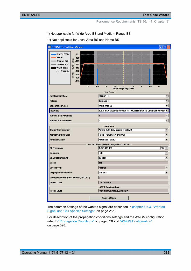
Test Case WizardEUTRA/LTE
362Operating Manual 1171.5177.12 ─ 21
*) Not applicable for Wide Area BS and Medium Range BS
**) Not applicable for Local Area BS and Home BS
The common settings of the wanted signal are described in chapter 8.6.3, "WantedSignal and Cell Specific Settings", on page 286.
For description of the propagation conditions settings and the AWGN configuration,refer to "Propagation Conditions" on page 328 and "AWGN Configuration"on page 328.
Performance Requirements (TS 36.141, Chapter 8)
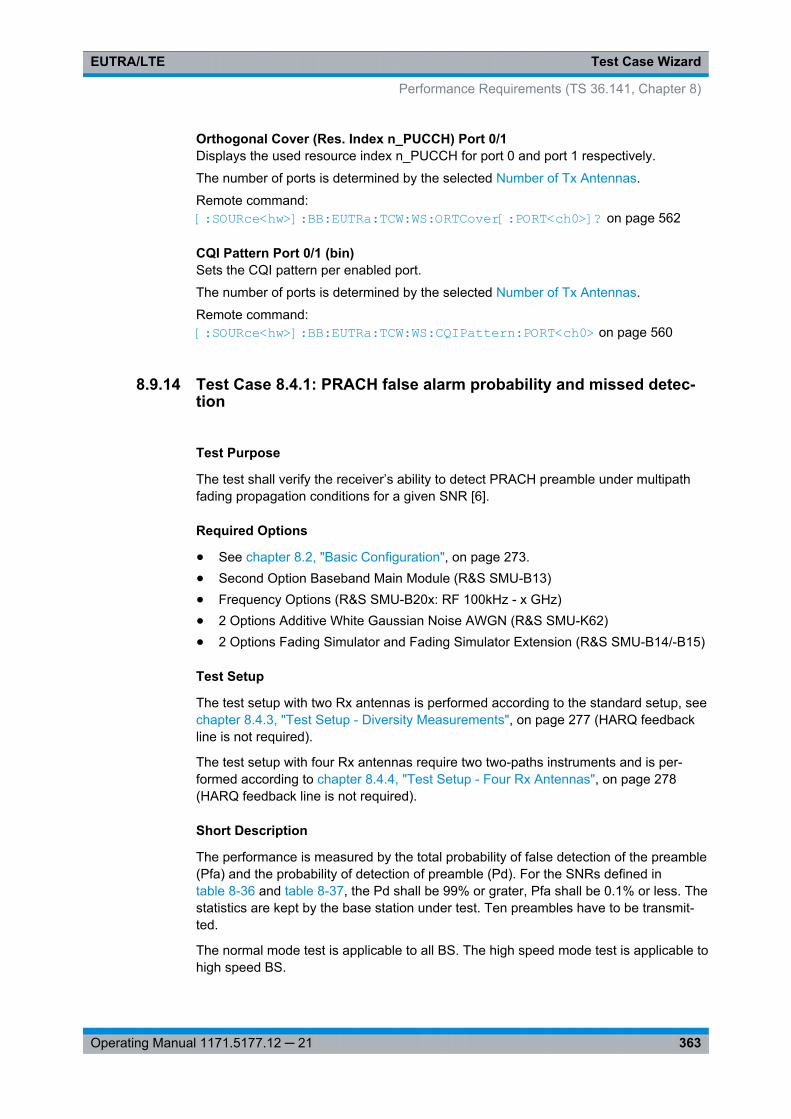
Test Case WizardEUTRA/LTE
363Operating Manual 1171.5177.12 ─ 21
Orthogonal Cover (Res. Index n_PUCCH) Port 0/1Displays the used resource index n_PUCCH for port 0 and port 1 respectively.
The number of ports is determined by the selected Number of Tx Antennas.
Remote command: [:SOURce<hw>]: BB: EUTRa:TCW: WS:ORTCover[: PORT<ch0>]? on page 562
CQI Pattern Port 0/1 (bin)Sets the CQI pattern per enabled port.
The number of ports is determined by the selected Number of Tx Antennas.
Remote command: [:SOURce<hw>]: BB:EUTRa: TCW:WS: CQIPattern: PORT<ch0> on page 560
8.9.14 Test Case 8.4.1: PRACH false alarm probability and missed detec-tion
Test Purpose
The test shall verify the receiver’s ability to detect PRACH preamble under multipathfading propagation conditions for a given SNR [6].
Required Options
● See chapter 8.2, "Basic Configuration", on page 273.● Second Option Baseband Main Module (R&S SMU-B13)● Frequency Options (R&S SMU-B20x: RF 100kHz - x GHz)● 2 Options Additive White Gaussian Noise AWGN (R&S SMU-K62)● 2 Options Fading Simulator and Fading Simulator Extension (R&S SMU-B14/-B15)
Test Setup
The test setup with two Rx antennas is performed according to the standard setup, seechapter 8.4.3, "Test Setup - Diversity Measurements", on page 277 (HARQ feedbackline is not required).
The test setup with four Rx antennas require two two-paths instruments and is per-formed according to chapter 8.4.4, "Test Setup - Four Rx Antennas", on page 278(HARQ feedback line is not required).
Short Description
The performance is measured by the total probability of false detection of the preamble(Pfa) and the probability of detection of preamble (Pd). For the SNRs defined intable 8-36 and table 8-37, the Pd shall be 99% or grater, Pfa shall be 0.1% or less. Thestatistics are kept by the base station under test. Ten preambles have to be transmit-ted.
The normal mode test is applicable to all BS. The high speed mode test is applicable tohigh speed BS.
Performance Requirements (TS 36.141, Chapter 8)
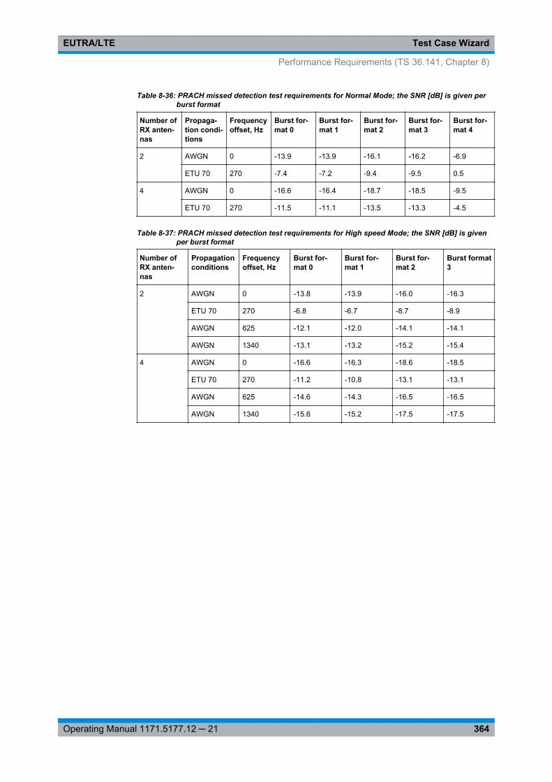
Test Case WizardEUTRA/LTE
364Operating Manual 1171.5177.12 ─ 21
Table 8-36: PRACH missed detection test requirements for Normal Mode; the SNR [dB] is given perburst format
Number ofRX anten-nas
Propaga-tion condi-tions
Frequencyoffset, Hz
Burst for-mat 0
Burst for-mat 1
Burst for-mat 2
Burst for-mat 3
Burst for-mat 4
2 AWGN 0 -13.9 -13.9 -16.1 -16.2 -6.9
ETU 70 270 -7.4 -7.2 -9.4 -9.5 0.5
4 AWGN 0 -16.6 -16.4 -18.7 -18.5 -9.5
ETU 70 270 -11.5 -11.1 -13.5 -13.3 -4.5
Table 8-37: PRACH missed detection test requirements for High speed Mode; the SNR [dB] is givenper burst format
Number ofRX anten-nas
Propagationconditions
Frequencyoffset, Hz
Burst for-mat 0
Burst for-mat 1
Burst for-mat 2
Burst format3
2 AWGN 0 -13.8 -13.9 -16.0 -16.3
ETU 70 270 -6.8 -6.7 -8.7 -8.9
AWGN 625 -12.1 -12.0 -14.1 -14.1
AWGN 1340 -13.1 -13.2 -15.2 -15.4
4 AWGN 0 -16.6 -16.3 -18.6 -18.5
ETU 70 270 -11.2 -10.8 -13.1 -13.1
AWGN 625 -14.6 -14.3 -16.5 -16.5
AWGN 1340 -15.6 -15.2 -17.5 -17.5
Performance Requirements (TS 36.141, Chapter 8)
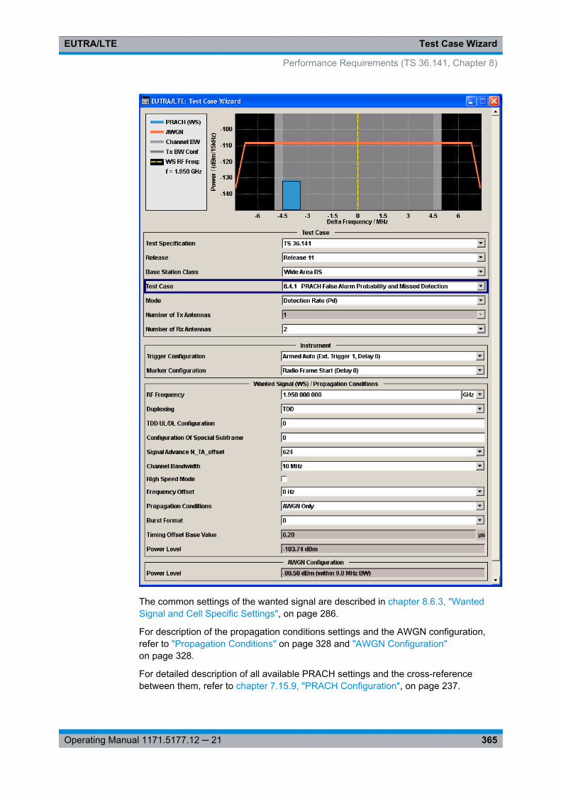
Test Case WizardEUTRA/LTE
365Operating Manual 1171.5177.12 ─ 21
The common settings of the wanted signal are described in chapter 8.6.3, "WantedSignal and Cell Specific Settings", on page 286.
For description of the propagation conditions settings and the AWGN configuration,refer to "Propagation Conditions" on page 328 and "AWGN Configuration"on page 328.
For detailed description of all available PRACH settings and the cross-referencebetween them, refer to chapter 7.15.9, "PRACH Configuration", on page 237.
Performance Requirements (TS 36.141, Chapter 8)
Test Case WizardEUTRA/LTE
366Operating Manual 1171.5177.12 ─ 21
ModeDetermines the measurements type, Pfa or Pd, the signal is generated for.
In "Detection Rate (Pd)" and "Alternating Pd and Pfa" mode, the generated sequenceis repeated cyclically. The first preamble is offset with start offset determined by TimingOffset Base Value. From preamble to preamble, the timing offset ("Delta t") of the pre-ambles is increased by 0.1 us.
"False Detec-tion Rate (Pfa)"
The generated signal is a noise like AWGN signal. This mode isintended for measurement of the total probability of false detection ofthe preamble (Pfa).
"DetectionRate (Pd)"
The generated signal is a sequence of 10 preamble and noise. Theduration of one single sequence is 5 frames in FDD and 10 frames inTDD duplexing mode.This mode is intended for measurement of the probability of detectionof preamble (Pd).
"Alternating Pdand Pfa"
The generated signal is a sequence of 10 enabled and 10 disabledpreambles; during the latest only noise is transmitted. The duration ofone single sequence is 10 FDD frames and 20 TDD frames.This mode is intended for measuring both the probability of detectionof preamble (Pd) and the probability of false detection of the pream-ble (Pfa) in one run.
Remote command: [:SOURce<hw>]: BB: EUTRa:TCW: GS:MODE on page 551
Configuration of Special Subframe(enabled for TDD duplexing mode only)
Sets the Special Subframe Configuration number (see also chapter 3.1.1, "OFDMAParameterization", on page 15).
Remote command: [:SOURce<hw>]: BB:EUTRa:TCW: WS:SPSFrame on page 564
High Speed ModeEnables a high speed mode (restricted preamble set) or the normal mode (unrestrictedpreamble set).
Remote command: [:SOURce<hw>]: BB: EUTRa:TCW: WS:HSMode on page 561
Frequency OffsetSets the frequency offset, as defined in table 8-36 and table 8-37.
Remote command: [:SOURce<hw>]: BB: EUTRa:TCW: WS:FROFfset on page 561
Burst FormatSets the burst format (see also "Preamble Format (Burst Format)" on page 237).
Performance Requirements (TS 36.141, Chapter 8)
Test Case WizardEUTRA/LTE
367Operating Manual 1171.5177.12 ─ 21
Burst format 4 is enabled only for TDD duplexing mode, special subframe configura-tions 5 to 8 and disabled high speed mode.
Remote command: [:SOURce<hw>]: BB:EUTRa: TCW:WS:BFORmat on page 559
Timing Offset Base ValueThe timing offset base value is set to 50% of the Ncs. This value determines the starttiming offset of the first preamble. From preamble to preamble, the timing offset ("Deltat") of the preambles is increased by 0.1 us and this sequence of timing offsets is restar-ted after 10 preambles.
Remote command: [:SOURce<hw>]: BB: EUTRa:TCW: WS:TIOBase? on page 564
Performance Requirements (TS 36.141, Chapter 8)
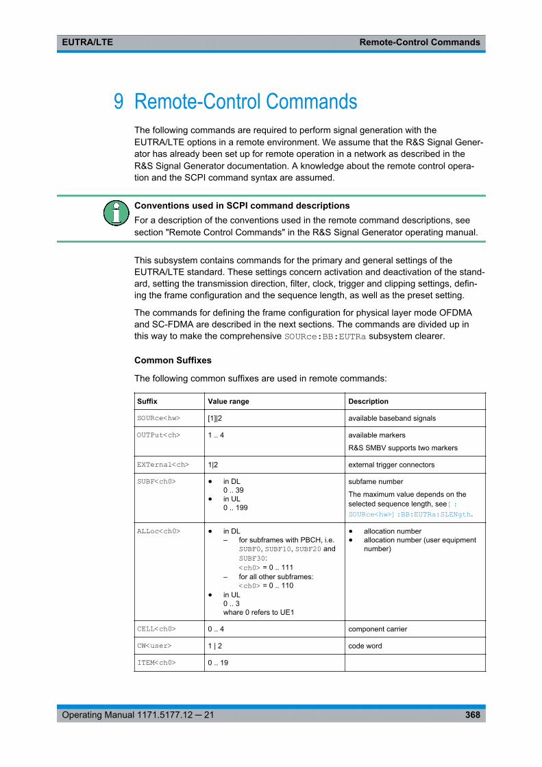
Remote-Control CommandsEUTRA/LTE
368Operating Manual 1171.5177.12 ─ 21
9 Remote-Control CommandsThe following commands are required to perform signal generation with theEUTRA/LTE options in a remote environment. We assume that the R&S Signal Gener-ator has already been set up for remote operation in a network as described in theR&S Signal Generator documentation. A knowledge about the remote control opera-tion and the SCPI command syntax are assumed.
Conventions used in SCPI command descriptionsFor a description of the conventions used in the remote command descriptions, seesection "Remote Control Commands" in the R&S Signal Generator operating manual.
This subsystem contains commands for the primary and general settings of theEUTRA/LTE standard. These settings concern activation and deactivation of the stand-ard, setting the transmission direction, filter, clock, trigger and clipping settings, defin-ing the frame configuration and the sequence length, as well as the preset setting.
The commands for defining the frame configuration for physical layer mode OFDMAand SC-FDMA are described in the next sections. The commands are divided up inthis way to make the comprehensive SOURce:BB:EUTRa subsystem clearer.
Common Suffixes
The following common suffixes are used in remote commands:
Suffix Value range Description
SOURce<hw> [1]|2 available baseband signals
OUTPut<ch> 1 .. 4 available markers
R&S SMBV supports two markers
EXTernal<ch> 1|2 external trigger connectors
SUBF<ch0> ● in DL0 .. 39
● in UL0 .. 199
subfame number
The maximum value depends on theselected sequence length, see [: SOURce<hw>]: BB:EUTRa: SLENgth.
ALLoc<ch0> ● in DL– for subframes with PBCH, i.e.
SUBF0, SUBF10, SUBF20 andSUBF30:<ch0> = 0 .. 111
– for all other subframes:<ch0> = 0 .. 110
● in UL0 .. 3whare 0 refers to UE1
● allocation number● allocation number (user equipment
number)
CELL<ch0> 0 .. 4 component carrier
CW<user> 1 | 2 code word
ITEM<ch0> 0 .. 19
Remote-Control CommandsEUTRA/LTE
369Operating Manual 1171.5177.12 ─ 21
Suffix Value range Description
UE<ch> [1]|2|3|4 determines the user equipment
PMCH<ch0> 0 .. 15 PM channel number
Placeholder <root>
For commands that read out or save files in the default directory, the default directoryis set using command MMEM:CDIRectory. The examples in this description use theplace holder <root> in the syntax of the command.
● D:\ - for selecting the internal hard disk of a Windows instrument
● E:\ - for selecting the memory stick which is inserted at the USB interface of aWindows instrument
● /var/user/ - for selecting the internal flash card of a Linux instrument
● /usb/ - for selecting the memory stick which is inserted at the USB interface of aLinux instrument.
Tasks (in manual or remote operation) that are also performed in the base unit in thesame way are not described here.
In particular, this includes:● Managing settings and data lists, i.e. storing and loading settings, creating and
accessing data lists, accessing files in a particular directory, etc.● Information on regular trigger, marker and clock signals as well as filter settings, if
appropriate.● General instrument configuration, such as configuring networks and remote opera-
tion● Using the common status registers
For a description of such tasks, see the R&S Signal Generator operating manual.
The following commands specific to the EUTRA/LTE standard are described here:
9.1 Primary Commands
[:SOURce<hw>]:BB:EUTRa:STATe................................................................................. 370[:SOURce<hw>]:BB:EUTRa:DUPLexing...........................................................................370[:SOURce<hw>]:BB:EUTRa:LINK.................................................................................... 370[:SOURce<hw>]:BB:EUTRa:PRESet................................................................................371[:SOURce<hw>]:BB:EUTRa:SETTing:CATalog................................................................. 371[:SOURce<hw>]:BB:EUTRa:SETTing:DEL....................................................................... 371[:SOURce<hw>]:BB:EUTRa:SETTing:LOAD.....................................................................372[:SOURce<hw>]:BB:EUTRa:SETTing:STORe...................................................................372[:SOURce<hw>]:BB:EUTRa:SETTing:STORe:FAST..........................................................372[:SOURce<hw>]:BB:EUTRa:SETTing:TMOD:TDD.............................................................373[:SOURce<hw>]:BB:EUTRa:SETTing:TMOD:DL............................................................... 373
Primary Commands
Remote-Control CommandsEUTRA/LTE
370Operating Manual 1171.5177.12 ─ 21
[:SOURce<hw>]:BB:EUTRa:SLENgth.............................................................................. 373[:SOURce<hw>]:BB:EUTRa:WAVeform:CREate............................................................... 373[:SOURce]:BB:EUTRa:VERSion?.................................................................................... 374
[:SOURce<hw>]:BB:EUTRa:STATe <State>
Activates modulation in accordance with the EUTRA/LTE standard. Activating thisstandard deactivates all the other digital standards and digital modulation modes.
In case of two-path instruments, this affects the same path.
Note: For two path instruments and configured antenna for for path B from inside pathA, enabling the LTE signal simulation will disable all other digital standards and digitalmodulation modes even in the path B.
BB:EUTR:STAT ON deactivates the other standards and digital modulation.
Parameters:<State> ON | OFF
*RST: OFF
Example: BB:EUTR:STAT ONactivates modulation in accordance with the EUTRA/LTE stand-ard.
Manual operation: See "State" on page 74
[:SOURce<hw>]:BB:EUTRa:DUPLexing <Duplexing>
Selects the duplexing mode. The duplexing mode determines how the uplink anddownlink signal are separated.
Parameters:<Duplexing> TDD | FDD
TDDThe same frequency is used for both directions of transmission(uplink and downlink). With one baseband, either only downlinkor only uplink signals can be generated.FDDDifferent frequencies are used for downlink and uplink direc-tions.*RST: FDD
Example: BB:EUTR:DUPL FDDselects frequency division duplexing.
Manual operation: See "Duplexing" on page 77
[:SOURce<hw>]:BB:EUTRa:LINK <Link>
Defines the transmission direction. The signal either corresponds to that of a base sta-tion (DOWN) or that of a subscriber station (UP).
Primary Commands
Remote-Control CommandsEUTRA/LTE
371Operating Manual 1171.5177.12 ─ 21
Parameters:<Link> DOWN | UP
*RST: DOWN
Example: BB:EUTR:LINK DOWNthe transmission direction selected is base station to subscriberstation. The signal corresponds to that of a base station.
Manual operation: See "Link Direction" on page 77
[:SOURce<hw>]:BB:EUTRa:PRESet
The command produces a standardized default for the EUTRA/LTE standard. The set-tings correspond to the *RST values specified for the commands.
All EUTRA/LTE settings are preset.
Example: BB:EUTR:PRESresets all the EUTRA/LTE settings to default values.
Manual operation: See "Set to Default" on page 74
[:SOURce<hw>]:BB:EUTRa:SETTing:CATalog <Catalog>
This command reads out the files with EUTRA/LTE settings in the default directory.The default directory is set using command MMEM:CDIRectory. Only files with the fileextension *.eutra will be listed.
Parameters:<Catalog> string
Example: MMEM:CDIR '<root>eutra'sets the default directory to <root>eutra.BB:EUTR:SETT:CAT?reads out all the files with EUTRA/LTE settings in the defaultdirectory.Response:'eutra1','eutra2'the files eutra1 and eutra2 are available.
Manual operation: See "Save/Recall..." on page 74
[:SOURce<hw>]:BB:EUTRa:SETTing:DEL <Filename>
Deletes the selected file with EUTRA/LTE settings. The directory is set using commandMMEM:CDIRectory. A path can also be specified, in which case the files in the speci-fied directory are read. The file extension may be omitted. Only files with the file exten-sion *.eutra will be deleted.
Setting parameters: <Filename> <file name>
Example: BB:EUTR:SETT:DEL 'eutra_1'deletes file eutra_1.
Primary Commands
Remote-Control CommandsEUTRA/LTE
372Operating Manual 1171.5177.12 ─ 21
Usage: Setting only
Manual operation: See "Save/Recall..." on page 74
[:SOURce<hw>]:BB:EUTRa:SETTing:LOAD <Filename>
Loads the selected file with EUTRA/LTE settings. The directory is set using commandMMEM:CDIRectory. A path can also be specified, in which case the files in the speci-fied directory are read. The file extension may be omitted. Only files with the file exten-sion *.eutra will be loaded.
Parameters:<Filename> string
Example: BB:EUTR:SETT:LOAD 'eutra_1'loads file eutra_1.
Manual operation: See "Save/Recall..." on page 74
[:SOURce<hw>]:BB:EUTRa:SETTing:STORe <Filename>
Stores the current EUTRA/LTE settings into the selected file. The directory is set usingcommand MMEM:CDIRectory. A path can also be specified, in which case the files inthe specified directory are read. Only the file name has to be entered. EUTRA/LTE set-tings are stored as files with the specific file extension *.eutra.
Parameters:<Filename> string
Example: BB:EUTR:SETT:STOR 'eutra_1'stores the current settings into file eutra_1.
Manual operation: See "Save/Recall..." on page 74
[:SOURce<hw>]:BB:EUTRa:SETTing:STORe:FAST <State>
Determines whether the instrument performs an absolute or a differential storing of thesettings.
Enable this function to accelerate the saving process by saving only the settings withvalues different to the default ones.
Note: This function is not affected by the "Preset" function.
Parameters:<State> 0 | 1 | OFF | ON
*RST: ON
Manual operation: See "Save/Recall..." on page 74
Primary Commands
Remote-Control CommandsEUTRA/LTE
373Operating Manual 1171.5177.12 ─ 21
[:SOURce<hw>]:BB:EUTRa:SETTing:TMOD:TDD <Tdd>[:SOURce<hw>]:BB:EUTRa:SETTing:TMOD:DL <Filename>
The command selects an EUTRA test model (E-TM) defined by the standard for thedownlink.
Parameters:<Filename> <test_model_name>
Example: BB:EUTR:SETT:TMOD:DL 'E-TM1_1__20MHz'selects the test model.
Manual operation: See "EUTRA Test Models (E-TM) Downlink" on page 93
[:SOURce<hw>]:BB:EUTRa:SLENgth <SLength>
Sets the sequence length of the signal in number of frames. The signal is calculated inadvance and output in the arbitrary waveform generator. The maximum number offrames is calculated as follows:
Max. No. of Frames = Arbitrary waveform memory size/(sampling rate x 10 ms).
Parameters:<SLength> integer
Range: 1 to Max. No. of FramesIncrement: 1*RST: 1
Example: BB:EUTR:SLEN 4selects the generation of 4 frames.
Manual operation: See "Sequence Length" on page 77
[:SOURce<hw>]:BB:EUTRa:WAVeform:CREate <Filename>
Creates a waveform using the current settings of the "EUTRA/LTE" dialog. The file isstored with the predefined file extension *.wv. The file name and the directory it isstored in are user-definable.
Note: Even for enabled Realtime Feedback, the waveform file is generated as if thisfunctionality is disabled.
Note: The sequence length of the generated ARB file is determined by the selectedSFN restart period ([:SOURce<hw>]: BB:EUTRa:DL: PBCH:SRPeriod ).
Setting parameters: <Filename> string
Example: MMEM:CDIR '<root>waveform'sets the default directory to <root>waveform.BB:EUTR:WAV:CRE 'eutra_1'creates the waveform file eutra_1.wv in the default directory.
Usage: Setting only
Primary Commands
Remote-Control CommandsEUTRA/LTE
374Operating Manual 1171.5177.12 ─ 21
Manual operation: See "Generate Waveform File…" on page 76
[:SOURce]:BB:EUTRa:VERSion?
The command queries the version of the 3GPP standard underlying the definitions.
Return values: <Version> string
Example: BB:EUTR:VERS?queries the 3GPP version.
Usage: Query only
Manual operation: See "3GPP Version" on page 76
9.2 Filter/Clipping/Power Settings
9.2.1 Filter Settings
[:SOURce<hw>]:BB:EUTRa:FILTer:TYPE........................................................................ 374[:SOURce<hw>]:BB:EUTRa:FILTer:MODE....................................................................... 375[:SOURce<hw>]:BB:EUTRa:FILTer:ILENgth..................................................................... 375[:SOURce<hw>]:BB:EUTRa:FILTer:ILENgth:AUTO........................................................... 375[:SOURce<hw>]:BB:EUTRa:FILTer:OSAMpling................................................................ 376[:SOURce<hw>]:BB:EUTRa:FILTer:OSAMpling:AUTO...................................................... 376[:SOURce<hw>]:BB:EUTRa:FILTer:PARameter:APCO25.................................................. 376[:SOURce<hw>]:BB:EUTRa:FILTer:PARameter:COSine....................................................377[:SOURce<hw>]:BB:EUTRa:FILTer:PARameter:COSine:COFS..........................................377[:SOURce<hw>]:BB:EUTRa:FILTer:PARameter:GAUSs.................................................... 377[:SOURce<hw>]:BB:EUTRa:FILTer:PARameter:LPASs..................................................... 377[:SOURce<hw>]:BB:EUTRa:FILTer:PARameter:LPASSEVM..............................................378[:SOURce<hw>]:BB:EUTRa:FILTer:PARameter:LTE:COFFactor........................................ 378[:SOURce<hw>]:BB:EUTRa:FILTer:PARameter:LTE:COFS............................................... 378[:SOURce<hw>]:BB:EUTRa:FILTer:PARameter:LTE:OPTimization.....................................379[:SOURce<hw>]:BB:EUTRa:FILTer:PARameter:LTE:ROFactor.......................................... 379[:SOURce<hw>]:BB:EUTRa:FILTer:PARameter:PGAuss................................................... 379[:SOURce<hw>]:BB:EUTRa:FILTer:PARameter:RCOSine................................................. 379[:SOURce<hw>]:BB:EUTRa:FILTer:PARameter:SPHase................................................... 380[:SOURce<hw>]:BB:EUTRa:FILTer:PARameter:USER...................................................... 380[:SOURce<hw>]:BB:EUTRa:SRATe:VARiation................................................................. 380
[:SOURce<hw>]:BB:EUTRa:FILTer:TYPE <Type>
Selects the baseband filter type.
Filter/Clipping/Power Settings
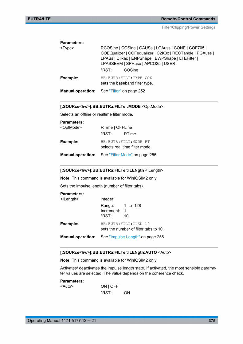
Remote-Control CommandsEUTRA/LTE
375Operating Manual 1171.5177.12 ─ 21
Parameters:<Type> RCOSine | COSine | GAUSs | LGAuss | CONE | COF705 |
COEQualizer | COFequalizer | C2K3x | RECTangle | PGAuss |LPASs | DIRac | ENPShape | EWPShape | LTEFilter |LPASSEVM | SPHase | APCO25 | USER*RST: COSine
Example: BB:EUTR:FILT:TYPE COSsets the baseband filter type.
Manual operation: See "Filter" on page 252
[:SOURce<hw>]:BB:EUTRa:FILTer:MODE <OptMode>
Selects an offline or realtime filter mode.
Parameters:<OptMode> RTime | OFFLine
*RST: RTime
Example: BB:EUTR:FILT:MODE RTselects real time filter mode.
Manual operation: See "Filter Mode" on page 255
[:SOURce<hw>]:BB:EUTRa:FILTer:ILENgth <ILength>
Note: This command is available for WinIQSIM2 only.
Sets the impulse length (number of filter tabs).
Parameters:<ILength> integer
Range: 1 to 128Increment: 1*RST: 10
Example: BB:EUTR:FILT:ILEN 10sets the number of filter tabs to 10.
Manual operation: See "Impulse Length" on page 256
[:SOURce<hw>]:BB:EUTRa:FILTer:ILENgth:AUTO <Auto>
Note: This command is available for WinIQSIM2 only.
Activates/ deactivates the impulse length state. If activated, the most sensible parame-ter values are selected. The value depends on the coherence check.
Parameters:<Auto> ON | OFF
*RST: ON
Filter/Clipping/Power Settings
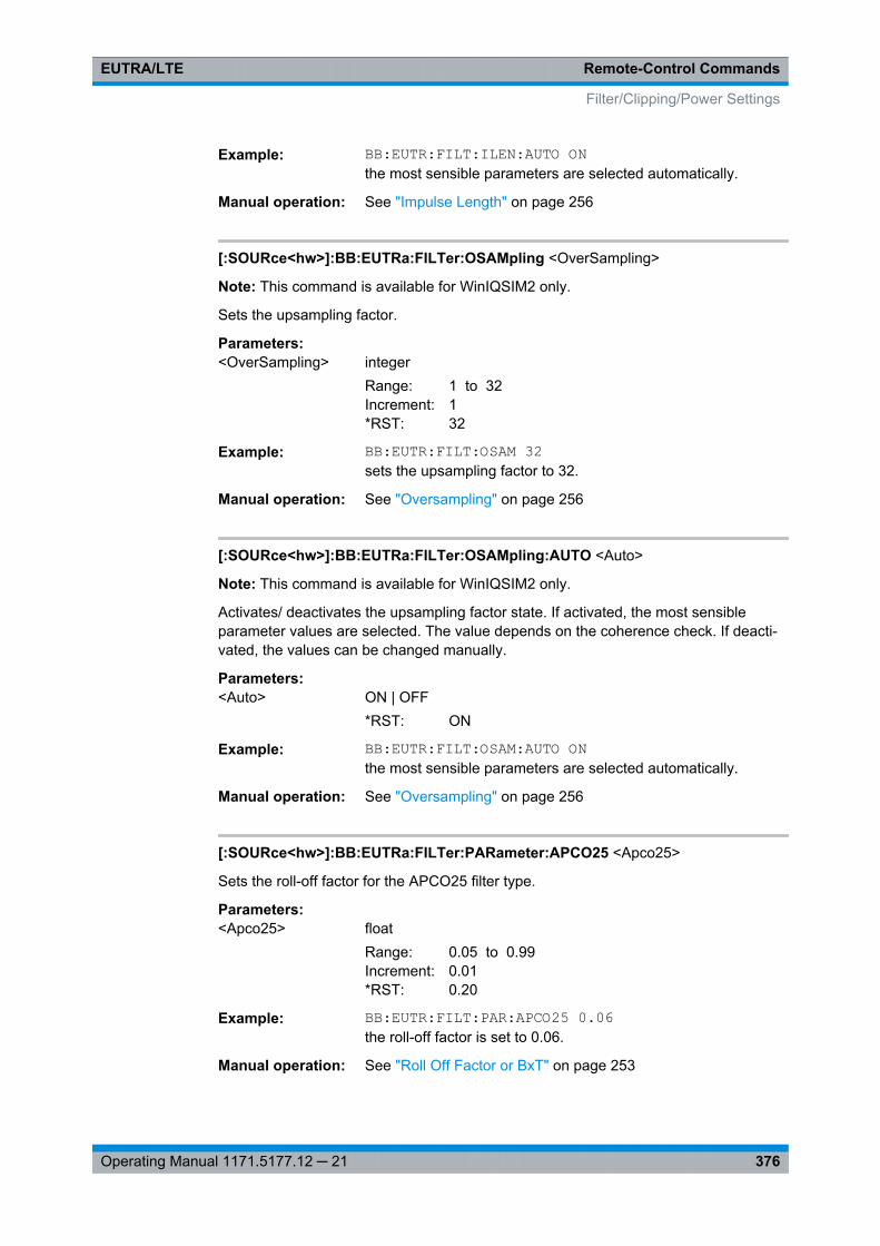
Remote-Control CommandsEUTRA/LTE
376Operating Manual 1171.5177.12 ─ 21
Example: BB:EUTR:FILT:ILEN:AUTO ONthe most sensible parameters are selected automatically.
Manual operation: See "Impulse Length" on page 256
[:SOURce<hw>]:BB:EUTRa:FILTer:OSAMpling <OverSampling>
Note: This command is available for WinIQSIM2 only.
Sets the upsampling factor.
Parameters:<OverSampling> integer
Range: 1 to 32Increment: 1*RST: 32
Example: BB:EUTR:FILT:OSAM 32sets the upsampling factor to 32.
Manual operation: See "Oversampling" on page 256
[:SOURce<hw>]:BB:EUTRa:FILTer:OSAMpling:AUTO <Auto>
Note: This command is available for WinIQSIM2 only.
Activates/ deactivates the upsampling factor state. If activated, the most sensibleparameter values are selected. The value depends on the coherence check. If deacti-vated, the values can be changed manually.
Parameters:<Auto> ON | OFF
*RST: ON
Example: BB:EUTR:FILT:OSAM:AUTO ONthe most sensible parameters are selected automatically.
Manual operation: See "Oversampling" on page 256
[:SOURce<hw>]:BB:EUTRa:FILTer:PARameter:APCO25 <Apco25>
Sets the roll-off factor for the APCO25 filter type.
Parameters:<Apco25> float
Range: 0.05 to 0.99Increment: 0.01*RST: 0.20
Example: BB:EUTR:FILT:PAR:APCO25 0.06the roll-off factor is set to 0.06.
Manual operation: See "Roll Off Factor or BxT" on page 253
Filter/Clipping/Power Settings
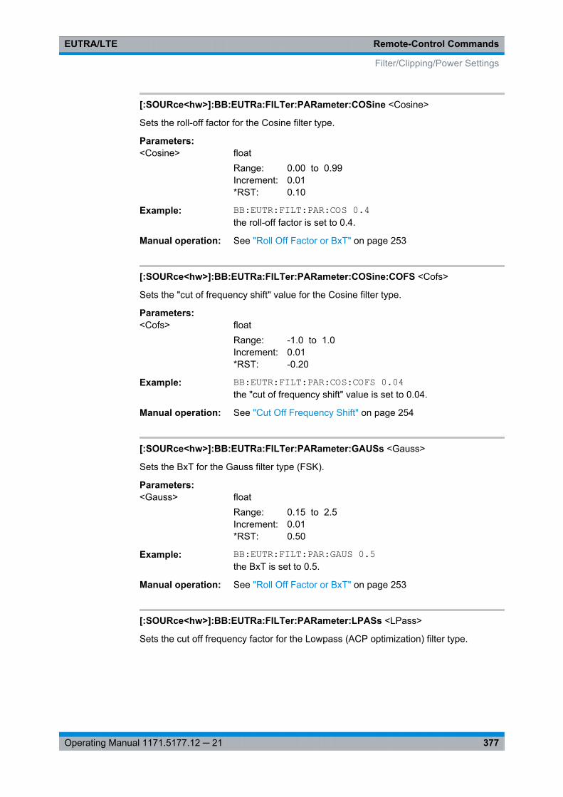
Remote-Control CommandsEUTRA/LTE
377Operating Manual 1171.5177.12 ─ 21
[:SOURce<hw>]:BB:EUTRa:FILTer:PARameter:COSine <Cosine>
Sets the roll-off factor for the Cosine filter type.
Parameters:<Cosine> float
Range: 0.00 to 0.99Increment: 0.01*RST: 0.10
Example: BB:EUTR:FILT:PAR:COS 0.4the roll-off factor is set to 0.4.
Manual operation: See "Roll Off Factor or BxT" on page 253
[:SOURce<hw>]:BB:EUTRa:FILTer:PARameter:COSine:COFS <Cofs>
Sets the "cut of frequency shift" value for the Cosine filter type.
Parameters:<Cofs> float
Range: -1.0 to 1.0Increment: 0.01*RST: -0.20
Example: BB:EUTR:FILT:PAR:COS:COFS 0.04the "cut of frequency shift" value is set to 0.04.
Manual operation: See "Cut Off Frequency Shift" on page 254
[:SOURce<hw>]:BB:EUTRa:FILTer:PARameter:GAUSs <Gauss>
Sets the BxT for the Gauss filter type (FSK).
Parameters:<Gauss> float
Range: 0.15 to 2.5Increment: 0.01*RST: 0.50
Example: BB:EUTR:FILT:PAR:GAUS 0.5the BxT is set to 0.5.
Manual operation: See "Roll Off Factor or BxT" on page 253
[:SOURce<hw>]:BB:EUTRa:FILTer:PARameter:LPASs <LPass>
Sets the cut off frequency factor for the Lowpass (ACP optimization) filter type.
Filter/Clipping/Power Settings
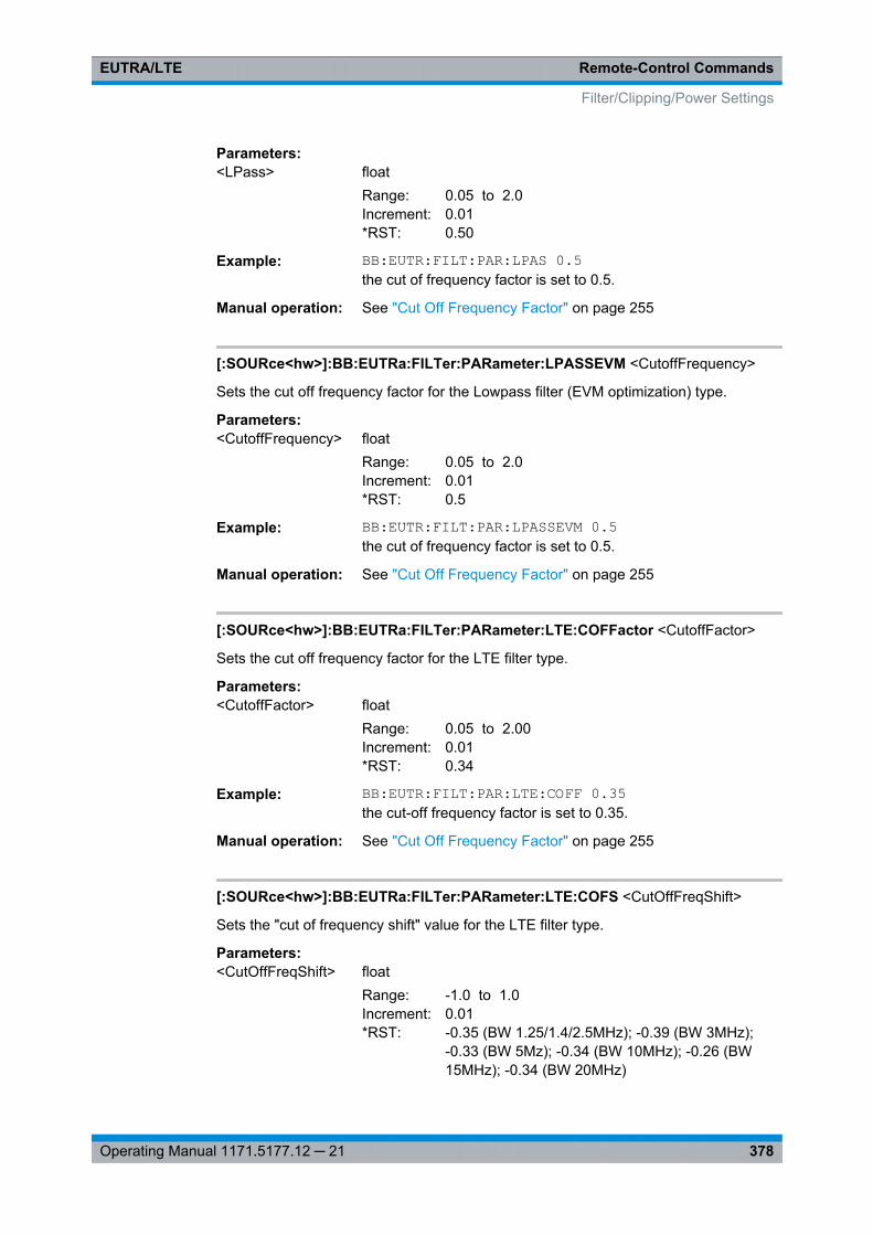
Remote-Control CommandsEUTRA/LTE
378Operating Manual 1171.5177.12 ─ 21
Parameters:<LPass> float
Range: 0.05 to 2.0Increment: 0.01*RST: 0.50
Example: BB:EUTR:FILT:PAR:LPAS 0.5the cut of frequency factor is set to 0.5.
Manual operation: See "Cut Off Frequency Factor" on page 255
[:SOURce<hw>]:BB:EUTRa:FILTer:PARameter:LPASSEVM <CutoffFrequency>
Sets the cut off frequency factor for the Lowpass filter (EVM optimization) type.
Parameters:<CutoffFrequency> float
Range: 0.05 to 2.0Increment: 0.01*RST: 0.5
Example: BB:EUTR:FILT:PAR:LPASSEVM 0.5the cut of frequency factor is set to 0.5.
Manual operation: See "Cut Off Frequency Factor" on page 255
[:SOURce<hw>]:BB:EUTRa:FILTer:PARameter:LTE:COFFactor <CutoffFactor>
Sets the cut off frequency factor for the LTE filter type.
Parameters:<CutoffFactor> float
Range: 0.05 to 2.00Increment: 0.01*RST: 0.34
Example: BB:EUTR:FILT:PAR:LTE:COFF 0.35the cut-off frequency factor is set to 0.35.
Manual operation: See "Cut Off Frequency Factor" on page 255
[:SOURce<hw>]:BB:EUTRa:FILTer:PARameter:LTE:COFS <CutOffFreqShift>
Sets the "cut of frequency shift" value for the LTE filter type.
Parameters:<CutOffFreqShift> float
Range: -1.0 to 1.0Increment: 0.01*RST: -0.35 (BW 1.25/1.4/2.5MHz); -0.39 (BW 3MHz);
-0.33 (BW 5Mz); -0.34 (BW 10MHz); -0.26 (BW15MHz); -0.34 (BW 20MHz)
Filter/Clipping/Power Settings
Remote-Control CommandsEUTRA/LTE
379Operating Manual 1171.5177.12 ─ 21
Example: BB:EUTR:FILT:PAR:LTE:COFS -0.3the cut-off frequency shift is set to -0.3.
Manual operation: See "Cut Off Frequency Shift" on page 254
[:SOURce<hw>]:BB:EUTRa:FILTer:PARameter:LTE:OPTimization <Optimization>
Defines the applied EUTRA/LTE filter. Available are EVM, ACP, ACPN (ACP Narrow),STD (a trade\-off between ACP and EVM) and BENU (Best EVM, no upsampling).
Parameters:<Optimization> STD | EVM | ACP | ACPN | BENU
*RST: EVM
Example: BB:EUTR:FILT:PAR:LTE:OPT ACPNselects ACP (Narrow) optimization.
Manual operation: See "Optimization" on page 252
[:SOURce<hw>]:BB:EUTRa:FILTer:PARameter:LTE:ROFactor <RollOffFactor>
Sets the roll-off factor for the LTE filter type.
Parameters:<RollOffFactor> float
Range: 0.00 to 1.0Increment: 0.01*RST: 0.1
Example: BB:EUTR:FILT:PAR:LTE:ROF 0.2the roll-off factor is set to 0.2.
Manual operation: See "Roll Off Factor or BxT" on page 253
[:SOURce<hw>]:BB:EUTRa:FILTer:PARameter:PGAuss <PGauss>
Sets the BxT for the Gauss filter type (pure).
Parameters:<PGauss> float
Range: 0.15 to 2.50Increment: 0.01*RST: 0.50
Example: BB:EUTR:FILT:PAR:PGA 0.5the BxT is set to 0.5.
Manual operation: See "Roll Off Factor or BxT" on page 253
[:SOURce<hw>]:BB:EUTRa:FILTer:PARameter:RCOSine <RCosine>
Sets the roll-off factor for the Root Cosine filter type.
Filter/Clipping/Power Settings
Remote-Control CommandsEUTRA/LTE
380Operating Manual 1171.5177.12 ─ 21
Parameters:<RCosine> float
Range: 0.0 to 1.0Increment: 0.01*RST: 0.22
Example: BB:EUTR:FILT:PAR:RCOS 0.4the roll-off factor is set to 0.4.
Manual operation: See "Roll Off Factor or BxT" on page 253
[:SOURce<hw>]:BB:EUTRa:FILTer:PARameter:SPHase <SPhase>
Sets the BxT for the Split Phase filter type.
Parameters:<SPhase> float
Range: 0.15 to 2.5Increment: 0.01*RST: 2.00
Example: BB:EUTR:FILT:PAR:SPH 2the BxT is set to 2.0
Manual operation: See "Roll Off Factor or BxT" on page 253
[:SOURce<hw>]:BB:EUTRa:FILTer:PARameter:USER <Filename>
The command selects the user-defined filter (*.vaf).
The directory applicable to the following command is defined with the commandMMEMory:CDIR. To access the files in this directory, only the file name is required,without the path and the file extension.
Parameters:<Filename> string
Example: BB:EUTR:FILT:TYPE USERselects the User filter type.MMEM:CDIR '<root>Filter_List'selects the directory for the user-defined filters.BB:EUTR:FILT:PAR:USER eutra_user_filterselects the user-defined filter.
Manual operation: See "Load User Filter" on page 253
[:SOURce<hw>]:BB:EUTRa:SRATe:VARiation <Variation>
Enters the output sample rate.
A variation of this parameter only affects the ARB clock rate; all other signal parame-ters remain unchanged. If the sampling rate in the "General Settings" menu ischanged, this parameter is reset to the chosen sampling rate.
Filter/Clipping/Power Settings
Remote-Control CommandsEUTRA/LTE
381Operating Manual 1171.5177.12 ─ 21
Parameters:<Variation> float
Range: 400Hz to 40MHzIncrement: 0.001Hz*RST: 15.36MHzDefault unit: Hz
Example: BB:EUTR:SRAT:VAR 400Hzsets the output sample rate to 400 Hz.
Manual operation: See "Sample Rate Variation " on page 255
9.2.2 Clipping Settings
[:SOURce<hw>]:BB:EUTRa:CLIPping:LEVel.................................................................... 381[:SOURce<hw>]:BB:EUTRa:CLIPping:MODE................................................................... 381[:SOURce<hw>]:BB:EUTRa:CLIPping:STATe...................................................................382
[:SOURce<hw>]:BB:EUTRa:CLIPping:LEVel <Level>
Sets the limit for level clipping. This value indicates at what point the signal is clipped.It is specified as a percentage, relative to the highest level. 100% indicates that clip-ping does not take place.
Level clipping is activated with the command BB:EUTR:CLIP:STAT ONParameters:<Level> integer
Range: 0PCT to 100PCTIncrement: 1PCT*RST: 100PCT
Example: BB:EUTR:CLIP:LEV 80PCTsets the limit for level clipping to 80% of the maximum level.BB:EUTR:CLIP:STAT ONactivates level clipping.
Manual operation: See "Clipping Level" on page 256
[:SOURce<hw>]:BB:EUTRa:CLIPping:MODE <Mode>
Sets the method for level clipping.
Parameters:<Mode> VECTor | SCALar
VECTorThe reference level is the amplitude | i+jq |.SCALarThe reference level is the absolute maximum of the I and Q val-ues.*RST: VECT
Filter/Clipping/Power Settings
Remote-Control CommandsEUTRA/LTE
382Operating Manual 1171.5177.12 ─ 21
Example: BB:EUTR:CLIP:MODE SCALselects the absolute maximum of all the I and Q values as thereference level.BB:EUTR:CLIP:LEV 80PCTsets the limit for level clipping to 80% of this maximum level.BB:EUTR:CLIP:STAT ONactivates level clipping.
Manual operation: See "Clipping Mode" on page 256
[:SOURce<hw>]:BB:EUTRa:CLIPping:STATe <State>
Activates level clipping (Clipping). The value is defined with the command[SOURce:]BB:EUTRa:CLIPping:LEVel, the mode of calculation with the command[SOURce:]BB:EUTRa:CLIPping:MODE.
Parameters:<State> ON | OFF
*RST: OFF
Example: BB:EUTR:CLIP:STAT ONactivates level clipping.
Manual operation: See "Clipping State" on page 256
9.2.3 Time Domain Windowing Settings
[:SOURce<hw>]:BB:EUTRa:TDW:STATe <State>
Activates/deactivates the time domain windowing.
Parameters:<State> ON | OFF
*RST: OFF
Example: BB:EUTR:TDW:STAT ONactivates time domain windowing.
Manual operation: See "State (Time Domain Windowing)" on page 251
[:SOURce<hw>]:BB:EUTRa:TDW:TRTime <TransitionTime>
Sets the transition time when time domain windowing is active.
Parameters:<TransitionTime> float
Range: 0.0us to 10.0usIncrement: 0.1us*RST: 5.0us
Example: BB:EUTR:TDW:TDT 2ussets ths transition time to 2us.
Filter/Clipping/Power Settings
Remote-Control CommandsEUTRA/LTE
383Operating Manual 1171.5177.12 ─ 21
Manual operation: See "Transition Time" on page 252
9.2.4 Power Settings
[:SOURce<hw>]:BB:EUTRa:POWC:LEVReference........................................................... 383[:SOURce<hw>]:BB:EUTRa:POWC:ORTLevel..................................................................383[:SOURce<hw>]:BB:EUTRa:POWC:REFChannel..............................................................384[:SOURce<hw>]:BB:EUTRa:POWC:REFSubframe?..........................................................384[:SOURce<hw>]:BB:EUTRa:POWC:RUE?........................................................................384
[:SOURce<hw>]:BB:EUTRa:POWC:LEVReference <LevelReference>
Defines the reference the "Level" display in the status bar is referring to.
Parameters:<LevelReference> FRMS | DRMS | URMS | UEBurst
FRMSThe displayed RMS and PEP are measured during the wholeframe.All frames are considered, not only the first one.DRMSThe displayed RMS and PEP are measured during the DL partof the frame (all DL subframes and the DwPTS).All frames are considered, not only the first one.URMSThe displayed RMS and PEP are measured during the UL partof the frame (all UL subframes and the UpPTS).All frames are considered, not only the first one.UEBurstThe displayed RMS and PEP are measured during a single sub-frame of a certain UE.*RST: FRMS
Example: BB:EUTR:POWC:LEVR UEBsets level reference to UE Burst RMS Power
Manual operation: See "Power Reference" on page 258
[:SOURce<hw>]:BB:EUTRa:POWC:ORTLevel <OffsRelatLevel>
Sets the power offset of the according baseband relative to the RMS level displayed inthe instrument's global Level display in the header of the instrument.
Parameters:<OffsRelatLevel> float
Range: -20.00dB to 0dBIncrement: 0.001dB*RST: 0dB
Filter/Clipping/Power Settings
Remote-Control CommandsEUTRA/LTE
384Operating Manual 1171.5177.12 ─ 21
Example: BB:EUTR:POWC:ORTL -1.0 dBsets the power offset of the baseband part
Manual operation: See "Power Offset Relative to Level Display" on page 258
[:SOURce<hw>]:BB:EUTRa:POWC:REFChannel <RefChannel>
Queries the channel type the measured RMS and PEP is referring to, if the Level Ref-erence is set to "UE Burst RMS Power"
Parameters:<RefChannel> NF | PUSCH | PUCCH | PRACH | SRS | PUCPUS
*RST: NF
Example: BB:EUTR:POWC:LEVR UEBsets level reference to UE Burst RMS PowerBB:EUTR:POWC:RUE?queries the channel type
Manual operation: See "Reference Channel" on page 259
[:SOURce<hw>]:BB:EUTRa:POWC:REFSubframe?
Queries the subframe the measured RMS and PEP is referring to, if the Level Refer-ence is set to "UE Burst RMS Power"
Return values: <RefSubframe> integer
Range: 0 to 39Increment: 1*RST: 0
Example: BB:EUTR:POWC:LEVR UEBsets level reference to UE Burst RMS PowerBB:EUTR:POWC:REFS?queries the reference subframe
Usage: Query only
Manual operation: See "Reference Subframe" on page 259
[:SOURce<hw>]:BB:EUTRa:POWC:RUE?
Queries the UE the measured RMS and PEP is referring to, if the Level Reference isset to "UE Burst RMS Power".
Return values: <ReferenceUe> UE1 | UE2 | UE3 | UE4
*RST: UE1
Filter/Clipping/Power Settings
Remote-Control CommandsEUTRA/LTE
385Operating Manual 1171.5177.12 ─ 21
Example: BB:EUTR:POWC:LEVR UEBsets level reference to UE Burst RMS PowerBB:EUTR:POWC:RUE?queries the reference UE
Usage: Query only
Manual operation: See "Reference UE" on page 258
9.3 Clock Settings
This section lists the remote control commands, necessary to configure the clock.
The clock settings are available for R&S SMx and R&S AMU instruments only.
[:SOURce<hw>]:BB:EUTRa:CLOCk:MODE......................................................................385[:SOURce<hw>]:BB:EUTRa:CLOCk:CUSTom.................................................................. 386[:SOURce<hw>]:BB:EUTRa:CLOCk:SOURce...................................................................386[:SOURce<hw>]:BB:EUTRa:CLOCk:MULTiplier................................................................ 386[:SOURce<hw>]:BB:EUTRa:CLOCk:SYNChronization:EXECute.........................................387[:SOURce<hw>]:BB:EUTRa:CLOCk:SYNChronization:MODE............................................ 387
[:SOURce<hw>]:BB:EUTRa:CLOCk:MODE <Mode>
Enters the type of externally supplied clock.
Parameters:<Mode> SAMP | MSAMp | CUSTom
SAMPleThe sample clock is supplied via the clock connector.MSAMpleA multiple of the clock is supplied and the clock is derived inter-nally from it.CUSTom(not for R&S SMBV)An external customer specific clock is supplied vie the clock con-nector. The sample clock is derived internally from it.Note: Custom External Clock source in baseband B is only sup-ported if baseband A is configured with EUTRA/LTE too. Fur-thermore the same settings for clock source and clock modehave to be set in baseband A and B. The user needs to takecare of the correct settings.*RST: SAMP
Example: SOURce1:BB:EUTRa:CLOCk:MODE SAMPleManual operation: See "Clock Mode" on page 269
Clock Settings
Remote-Control CommandsEUTRA/LTE
386Operating Manual 1171.5177.12 ─ 21
[:SOURce<hw>]:BB:EUTRa:CLOCk:CUSTom <Custom>
Specifies the sample clock for clock type Custom (BB:EUTRa:CLOCk:MODE CUSTom)in the case of an external clock source.
Note: Custom External Clock source in baseband B is only supported if baseband A isconfigured with EUTRA/LTE too. Furthermore the same settings for clock source andclock mode have to be set in baseband A and B. The user needs to take care of thecorrect settings.
Parameters:<Custom> integer
Range: 25000 to 40E6*RST: 38.4E6
Example: BB:EUTR:CLOC:SOUR EXTselects an external clock reference.BB:EUTR:CLOC:MODE CUSTomselects clock type Custom.BB:EUTR:CLOC:CUSTom 38400000the custom external clock is 38.4MHz.
Manual operation: See "Custom External Clock" on page 270
[:SOURce<hw>]:BB:EUTRa:CLOCk:SOURce <Source>
Selects the clock source.
Parameters:<Source> INTernal | EXTernal
INTernalThe internal clock reference is used.EXTernalThe external clock reference is supplied to the CLOCK connec-tor. The type of the external clock is specified with commandBB:EURA:CLOCk:MODE*RST: INTernal
Example: BB:EUTR:CLOC:SOUR EXTselects an external clock reference. The clock is supplied via theCLOCK connector.BB:EUTR:CLOC:MODE SAMPspecifies that a sample clock is supplied via the CLOCK connec-tor:
Manual operation: See "Clock Source" on page 269
[:SOURce<hw>]:BB:EUTRa:CLOCk:MULTiplier <Multiplier>
Specifies the multiplier for clock type multiplied.
Clock Settings
Remote-Control CommandsEUTRA/LTE
387Operating Manual 1171.5177.12 ─ 21
Parameters:<Multiplier> integer
Range: 1 to 64Increment: 1*RST: 4
Example: SOURce1:BB:EUTRa:CLOCk:SOURce EXTSOURce1:BB:EUTRa:CLOCk:MODE MSAMpleselects clock typeSOURce1:BB:EUTRa:CLOCk:MULTiplier 12the multiplier for the external clock rate is 12.
Manual operation: See "Clock Multiplier" on page 270
[:SOURce<hw>]:BB:EUTRa:CLOCk:SYNChronization:EXECute
For R&S SMBV only
Performs automatically adjustment of the instrument's settings required for the syn-chronization mode, set with the command BB:EUTR:SYNC:MODE.
Example: BB:EUTR:CLOC:SYNC:MODE MASTthe instrument is configured to work as a master one.BB:EUTR:CLOCK:SYNC:EXECall synchronization's settings are adjusted accordingly.
[:SOURce<hw>]:BB:EUTRa:CLOCk:SYNChronization:MODE <Mode>
For R&S SMBV only
Selects the synchronization mode.
This parameter is used to enable generation of very precise synchronous signal of sev-eral connected R&S SMBVs.
Note: If several instruments are connected, the connecting cables from the masterinstrument to the slave one and between each two consecutive slave instruments musthave the same length and type.
Avoid unnecessary cable length and branching points.
Clock Settings
Remote-Control CommandsEUTRA/LTE
388Operating Manual 1171.5177.12 ─ 21
Parameters:<Mode> NONE | MASTer | SLAVe
NONEThe instrument is working in stand-alone mode.MASTerThe instrument provides all connected instrument with its syn-chronisation (including the trigger signal) and reference clocksignal.SLAVeThe instrument receives the synchronisation and reference clocksignal from another instrument working in a master mode.*RST: NONE
Example: BB:EUTR:CLOC:SYNC:MODE MASTthe instrument is configured to work as a master one.
Manual operation: See "Sync. Mode" on page 268
9.4 Timing Configuration
[:SOURce<hw>]:BB:EUTRa:TIMC:NTAoffset <NtaOffset>
For R&S SMU and R&S AMU instruments only
Sets the parameter NTA offset as defined in the 3GPP TS 36.211.
Parameters:<NtaOffset> NTA0 | NTA624 | 0
*RST: NTA0
Example: BB:EUTR:TIMC:NTA NTA0sets parameter NTA offset
Manual operation: See "Signal Advance N_TA_offset" on page 265
9.5 Trigger Settings
The trigger settings are available for R&S SMx and R&S AMU instruments only.
EXTernal<ch>The numeric suffix to EXTernal<ch> distinguishes between the external trigger viathe TRIGGER 1 (suffix 1) and TRIGGER 2 (suffix 2) connector.
Timing Configuration
Remote-Control CommandsEUTRA/LTE
389Operating Manual 1171.5177.12 ─ 21
[:SOURce<hw>]:BB:EUTRa[:TRIGger]:SEQuence............................................................ 389[:SOURce<hw>]:BB:EUTRa:TRIGger:ARM:EXECute........................................................ 390[:SOURce<hw>]:BB:EUTRa:TRIGger:DELay:UNIT............................................................391[:SOURce<hw>]:BB:EUTRa:TRIGger:EXECute.................................................................391[:SOURce<hw>]:BB:EUTRa:TRIGger:EXTernal<ch>:RDELay?.......................................... 391[:SOURce<hw>]:BB:EUTRa:TRIGger:EXTernal<ch>:TDELay.............................................392[:SOURce<hw>]:BB:EUTRa:TRIGger:EXTernal:SYNChronize:OUTPut............................... 392[:SOURce<hw>]:BB:EUTRa:TRIGger:OBASeband:DELay................................................. 393[:SOURce<hw>]:BB:EUTRa:TRIGger:OBASeband:INHibit................................................. 393[:SOURce<hw>]:BB:EUTRa:TRIGger:OBASeband:RDELay?............................................. 393[:SOURce<hw>]:BB:EUTRa:TRIGger:OBASeband:TDELay............................................... 394[:SOURce<hw>]:BB:EUTRa:TRIGger:RMODe?................................................................ 394[:SOURce<hw>]:BB:EUTRa:TRIGger:SLENgth.................................................................395[:SOURce<hw>]:BB:EUTRa:TRIGger:SLUNit....................................................................395[:SOURce<hw>]:BB:EUTRa:TRIGger:SOURce................................................................. 396[:SOURce<hw>]:BB:EUTRa:TRIGger[:EXTernal<ch>]:DELay.............................................396[:SOURce<hw>]:BB:EUTRa:TRIGger[:EXTernal<ch>]:INHibit.............................................397
[:SOURce<hw>]:BB:EUTRa[:TRIGger]:SEQuence <TriggerMode>
Selects the trigger mode.
Trigger Settings
Remote-Control CommandsEUTRA/LTE
390Operating Manual 1171.5177.12 ─ 21
Parameters:<TriggerMode> AUTO | RETRigger | AAUTo | ARETrigger | SINGle
AUTOThe modulation signal is generated continuously.RETRiggerThe modulation signal is generated continuously. A trigger event(internal or external) causes a restart.AAUToThe modulation signal is generated only when a trigger eventoccurs. After the trigger event the signal is generated continu-ously. Signal generation is stopped with commandBB:EUTR:TRIG:ARM:EXEC and started again when a triggerevent occurs.This mode is used for example for Base Station Tests if a framemarker from the device under test starts the signal output. Sub-sequent frame markers will not cause a restart of the signal.ARETriggerThe modulation signal is generated only when a trigger eventoccurs. The device automatically toggles to RETR mode. Everysubsequent trigger event causes a restart.Signal generation is stopped with commandBB:EUTR:TRIG:ARM:EXEC and started again when a triggerevent occurs.SINGleThe modulation signal is generated only when a trigger eventoccurs. Then the signal is generated once to the length specifiedwith command BB:EUTR:TRIG:SLEN. Every subsequent triggerevent causes a restart.*RST: AUTO
Example: BB:EUTR:SEQ AAUTsets the "Armed_auto" trigger mode; the device waits for the firsttrigger (e.g. with *TRG) and then generates the signal continu-ously.
Manual operation: See "Trigger Mode" on page 260
[:SOURce<hw>]:BB:EUTRa:TRIGger:ARM:EXECute
Stops signal generation for trigger modes "Armed_Auto" and "Armed_Retrigger". Asubsequent internal or external trigger event restarts signal generation.
Trigger Settings
Remote-Control CommandsEUTRA/LTE
391Operating Manual 1171.5177.12 ─ 21
Example: BB:EUTR:TRIG:SOUR INTsets internal triggering.BB:EUTR:TRIG:SEQ ARETsets Armed_Retrigger mode, i.e. every trigger event causes sig-nal generation to restart.BB:EUTR:TRIG:EXECexecutes a trigger, signal generation is started.BB:EUTR:TRIG:ARM:EXECsignal generation is stopped.BB:EUTR:TRIG:EXECexecutes a trigger, signal generation is started again.
Usage: Event
Manual operation: See "Arm" on page 78
[:SOURce<hw>]:BB:EUTRa:TRIGger:DELay:UNIT <DelUnit>
Defines the unit of the external and other baseband trigger delay.
Parameters:<DelUnit> SAMPle | TIME
Range: SAMPle to TIME*RST: SAMPle
Example: SOURce1:BB:EUTRa:TRIGger:DELay:UNIT SAMPlesets the external trigger delay to samples.
Manual operation: See "Trigger Delay Unit" on page 264
[:SOURce<hw>]:BB:EUTRa:TRIGger:EXECute
Executes a trigger. The internal trigger source must be selected using the commandBB:EUTR:TRIG:SOUR INT and a trigger mode other than AUTO must be selectedusing the command BB:EUTR:TRIG:SEQ.
Example: BB:EUTR:TRIG:SOUR INTsets internal triggering.BB:EUTR:TRIG:SEQ RETRsets Retrigger mode, i.e. every trigger event causes signal gen-eration to restart.BB:EUTR:TRIG:EXECexecutes a trigger.
Usage: Event
Manual operation: See "Execute Trigger" on page 78
[:SOURce<hw>]:BB:EUTRa:TRIGger:EXTernal<ch>:RDELay?
Queries the actual external trigger delay (expressed in time unit).
Trigger Settings
Remote-Control CommandsEUTRA/LTE
392Operating Manual 1171.5177.12 ─ 21
Return values: <ExtResultDelay> float
Range: 0 to 688Increment: 250E-12*RST: 0
Example: BB:EUTR:TRIG:EXT:RDEL?Response: 5.12E-6 the resulting delay of the external triggersignal is 5.12 micro seconds.
Usage: Query only
Manual operation: See "Actual External Delay" on page 264
[:SOURce<hw>]:BB:EUTRa:TRIGger:EXTernal<ch>:TDELay <Delay>
Defines the trigger delay (expressed in time units) for external triggering.
Parameters:<Delay> float
Range: 0 to 688Increment: 250E-12*RST: 0
Example: BB:EUTR:TRIG:EXT:TDEL 5E-6sets a delay of 5 micro seconds for the trigger.
Manual operation: See "Trigger Delay" on page 264
[:SOURce<hw>]:BB:EUTRa:TRIGger:EXTernal:SYNChronize:OUTPut<OutputState>
(enabled for Trigger Source External)
Enables/disables output of the signal synchronous to the external trigger event.
For R&S SMBV instruments:
See also section "Sync. Output to External Trigger" on page 262 for a detailed descrip-tion of the applications of this setting.
Parameters:<OutputState> ON | OFF
ONThe signal calculation starts simultaneously with the externaltrigger event but because of the instrument’s processing timethe first samples are cut off and no signal is outputted. Afterelapsing of the internal processing time, the output signal is syn-chronous to the trigger event.OFFThe signal output begins after elapsing of the processing timeand starts with sample 0, i.e. the complete signal is outputted.*RST: ON
Trigger Settings
Remote-Control CommandsEUTRA/LTE
393Operating Manual 1171.5177.12 ─ 21
Example: BB:EUTR:TRIG:SOUR EXTsets external triggering.BB:EUTR:TRIG:EXT:SYNC:OUTP ONenables synchrounous output to external trigger
Manual operation: See "Sync. Output to External Trigger" on page 262
[:SOURce<hw>]:BB:EUTRa:TRIGger:OBASeband:DELay <Delay>
Specifies the trigger delay (expressed as a number of samples) for triggering by thetrigger signal from the second path (two-path instruments only).
Parameters:<Delay> integer
Range: 0 to 65535Increment: 1*RST: 0
Example: BB:EUTR:TRIG:SOUR OBASsets for path A the internal trigger executed by the trigger signalfrom the second path (path B).BB:EUTR:TRIG:OBAS:DEL 50sets a delay of 50 samples for the trigger.
Manual operation: See "Trigger Delay" on page 264
[:SOURce<hw>]:BB:EUTRa:TRIGger:OBASeband:INHibit <Inhibit>
Specifies the number of samples by which a restart is to be inhibited following a triggerevent. This command applies only for triggering by the second path.
Parameters:<Inhibit> integer
Range: 0 to 2^26-1Increment: 1*RST: 0
Example: BB:EUTR:TRIG:SOUR OBASsets for path A the internal trigger executed by the trigger signalfrom the second path (path B).BB:EUTR:TRIG:OBAS:INH 200sets a restart inhibit for 200 samples following a trigger event.
Manual operation: See "Trigger Inhibit" on page 265
[:SOURce<hw>]:BB:EUTRa:TRIGger:OBASeband:RDELay?
Queries the actual trigger delay (expressed in time units) of the trigger signal from thesecond path (two-path instruments only).
Trigger Settings
Remote-Control CommandsEUTRA/LTE
394Operating Manual 1171.5177.12 ─ 21
Return values: <IntOthRDelay> float
Range: 0 to 688Increment: 250E-12*RST: 0
Example: BB:EUTR:TRIG:SOUR OBASsets for path A the internal trigger executed by the trigger signalfrom the second path (path B).BB:EUTR:TRIG:OBAS:RDEL?Response: 3.2E-6 the resulting delay of the internal trigger sig-nal is 3.2 micro seconds.
Usage: Query only
Manual operation: See "Actual External Delay" on page 264
[:SOURce<hw>]:BB:EUTRa:TRIGger:OBASeband:TDELay <IntOthTDelay>
Specifies the trigger delay (expressed in time units) for triggering by the trigger signalfrom the second path (two-path instruments only).
Parameters:<IntOthTDelay> float
Range: 0 to 688Increment: 250E-12*RST: 0
Example: BB:EUTR:TRIG:SOUR OBASsets for path A the internal trigger executed by the trigger signalfrom the second path (path B).BB:EUTR:TRIG:OBAS:TDEL 1.5E-6sets a delay of 1.5 micro seconds for the trigger.
Manual operation: See "Trigger Delay" on page 264
[:SOURce<hw>]:BB:EUTRa:TRIGger:RMODe?
The command queries the current status of signal generation for all trigger modes withEUTRA/LTE modulation on.
Return values: <RunMode> RUN | STOP
RUNthe signal is generated. A trigger event occurred in the triggeredmode.STOPthe signal is not generated. A trigger event did not occur in thetriggered modes, or signal generation was stopped by the com-mand BB:EUTRa:TRIG:ARM:EXECute (armed trigger modesonly).
Trigger Settings
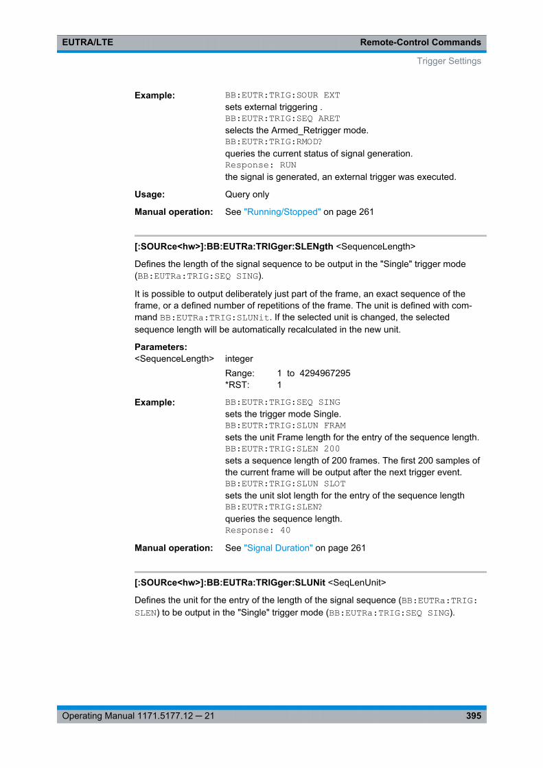
Remote-Control CommandsEUTRA/LTE
395Operating Manual 1171.5177.12 ─ 21
Example: BB:EUTR:TRIG:SOUR EXTsets external triggering .BB:EUTR:TRIG:SEQ ARETselects the Armed_Retrigger mode.BB:EUTR:TRIG:RMOD?queries the current status of signal generation.Response: RUNthe signal is generated, an external trigger was executed.
Usage: Query only
Manual operation: See "Running/Stopped" on page 261
[:SOURce<hw>]:BB:EUTRa:TRIGger:SLENgth <SequenceLength>
Defines the length of the signal sequence to be output in the "Single" trigger mode(BB:EUTRa:TRIG:SEQ SING).
It is possible to output deliberately just part of the frame, an exact sequence of theframe, or a defined number of repetitions of the frame. The unit is defined with com-mand BB:EUTRa:TRIG:SLUNit. If the selected unit is changed, the selectedsequence length will be automatically recalculated in the new unit.
Parameters:<SequenceLength> integer
Range: 1 to 4294967295*RST: 1
Example: BB:EUTR:TRIG:SEQ SINGsets the trigger mode Single.BB:EUTR:TRIG:SLUN FRAMsets the unit Frame length for the entry of the sequence length.BB:EUTR:TRIG:SLEN 200sets a sequence length of 200 frames. The first 200 samples ofthe current frame will be output after the next trigger event.BB:EUTR:TRIG:SLUN SLOTsets the unit slot length for the entry of the sequence lengthBB:EUTR:TRIG:SLEN?queries the sequence length.Response: 40
Manual operation: See "Signal Duration" on page 261
[:SOURce<hw>]:BB:EUTRa:TRIGger:SLUNit <SeqLenUnit>
Defines the unit for the entry of the length of the signal sequence (BB:EUTRa:TRIG:SLEN) to be output in the "Single" trigger mode (BB:EUTRa:TRIG:SEQ SING).
Trigger Settings
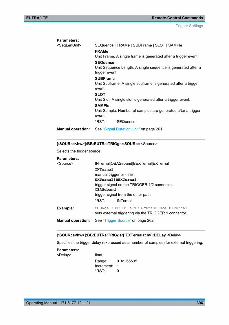
Remote-Control CommandsEUTRA/LTE
396Operating Manual 1171.5177.12 ─ 21
Parameters:<SeqLenUnit> SEQuence | FRAMe | SUBFrame | SLOT | SAMPle
FRAMeUnit Frame. A single frame is generated after a trigger event.SEQuenceUnit Sequence Length. A single sequence is generated after atrigger event.SUBFrameUnit Subframe. A single subframe is generated after a triggerevent.SLOTUnit Slot. A single slot is generated after a trigger event.SAMPleUnit Sample. Number of samples are generated after a triggerevent.*RST: SEQuence
Manual operation: See "Signal Duration Unit" on page 261
[:SOURce<hw>]:BB:EUTRa:TRIGger:SOURce <Source>
Selects the trigger source.
Parameters:<Source> INTernal|OBASeband|BEXTernal|EXTernal
INTernalmanual trigger or *TRG.EXTernal|BEXTernaltrigger signal on the TRIGGER 1/2 connector.OBASebandtrigger signal from the other path*RST: INTernal
Example: SOURce1:BB:EUTRa:TRIGger:SOURce EXTernalsets external triggering via the TRIGGER 1 connector.
Manual operation: See "Trigger Source" on page 262
[:SOURce<hw>]:BB:EUTRa:TRIGger[:EXTernal<ch>]:DELay <Delay>
Specifies the trigger delay (expressed as a number of samples) for external triggering.
Parameters:<Delay> float
Range: 0 to 65535Increment: 1*RST: 0
Trigger Settings
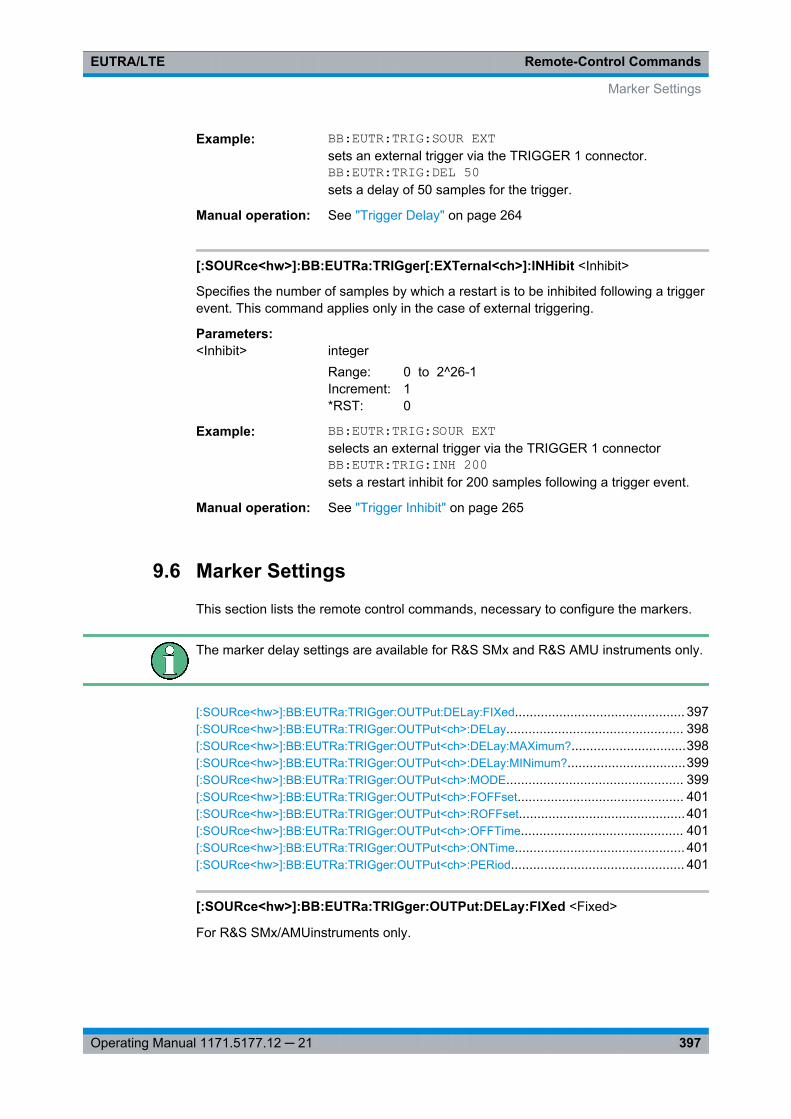
Remote-Control CommandsEUTRA/LTE
397Operating Manual 1171.5177.12 ─ 21
Example: BB:EUTR:TRIG:SOUR EXTsets an external trigger via the TRIGGER 1 connector.BB:EUTR:TRIG:DEL 50sets a delay of 50 samples for the trigger.
Manual operation: See "Trigger Delay" on page 264
[:SOURce<hw>]:BB:EUTRa:TRIGger[:EXTernal<ch>]:INHibit <Inhibit>
Specifies the number of samples by which a restart is to be inhibited following a triggerevent. This command applies only in the case of external triggering.
Parameters:<Inhibit> integer
Range: 0 to 2^26-1Increment: 1*RST: 0
Example: BB:EUTR:TRIG:SOUR EXTselects an external trigger via the TRIGGER 1 connectorBB:EUTR:TRIG:INH 200sets a restart inhibit for 200 samples following a trigger event.
Manual operation: See "Trigger Inhibit" on page 265
9.6 Marker Settings
This section lists the remote control commands, necessary to configure the markers.
The marker delay settings are available for R&S SMx and R&S AMU instruments only.
[:SOURce<hw>]:BB:EUTRa:TRIGger:OUTPut:DELay:FIXed.............................................. 397[:SOURce<hw>]:BB:EUTRa:TRIGger:OUTPut<ch>:DELay................................................ 398[:SOURce<hw>]:BB:EUTRa:TRIGger:OUTPut<ch>:DELay:MAXimum?...............................398[:SOURce<hw>]:BB:EUTRa:TRIGger:OUTPut<ch>:DELay:MINimum?................................399[:SOURce<hw>]:BB:EUTRa:TRIGger:OUTPut<ch>:MODE................................................ 399[:SOURce<hw>]:BB:EUTRa:TRIGger:OUTPut<ch>:FOFFset............................................. 401[:SOURce<hw>]:BB:EUTRa:TRIGger:OUTPut<ch>:ROFFset.............................................401[:SOURce<hw>]:BB:EUTRa:TRIGger:OUTPut<ch>:OFFTime............................................ 401[:SOURce<hw>]:BB:EUTRa:TRIGger:OUTPut<ch>:ONTime.............................................. 401[:SOURce<hw>]:BB:EUTRa:TRIGger:OUTPut<ch>:PERiod............................................... 401
[:SOURce<hw>]:BB:EUTRa:TRIGger:OUTPut:DELay:FIXed <Fixed>
For R&S SMx/AMUinstruments only.
Marker Settings

Remote-Control CommandsEUTRA/LTE
398Operating Manual 1171.5177.12 ─ 21
The command restricts the marker delay setting range to the dynamic range. In thisrange the delay can be set without restarting the marker and signal. If a delay isentered in setting ON but is outside this range, the maximum possible delay is set andan error message is generated.
Parameters:<Fixed> 0 | 1 | OFF | ON
*RST: OFF
Example: BB:EUTR:TRIG:OUTP:DEL:FIX ONrestricts the marker signal delay setting range to the dynamicrange.
Manual operation: See "Fix marker delay to current range" on page 268
[:SOURce<hw>]:BB:EUTRa:TRIGger:OUTPut<ch>:DELay <Delay>
Defines the delay between the signal on the marker outputs and the start of the signal,expressed in terms of samples. CommandBB:EUTRa:TRIGger:OUTPut:DELay:FIXed can be used to restrict the range ofvalues to the dynamic range, i.e. the range within which a delay of the marker signalscan be set without restarting the marker and signal.
Parameters:<Delay> integer
Range: 0 samples to 2^24-1 samplesIncrement: 1 sample*RST: 0 samples
Example: BB:EUTR:TRIG:OUTP2:DEL 1600sets a delay of 1600 samples for the corresponding marker sig-nal.
Manual operation: See "Marker x Delay" on page 268
[:SOURce<hw>]:BB:EUTRa:TRIGger:OUTPut<ch>:DELay:MAXimum?
The command queries the maximum marker delay for settingBB:EUTRa:TRIG:OUTP:DEL:FIX ON.
Return values: <Maximum> float
Range: 0 to maxIncrement: 0.001*RST: 2000
Marker Settings
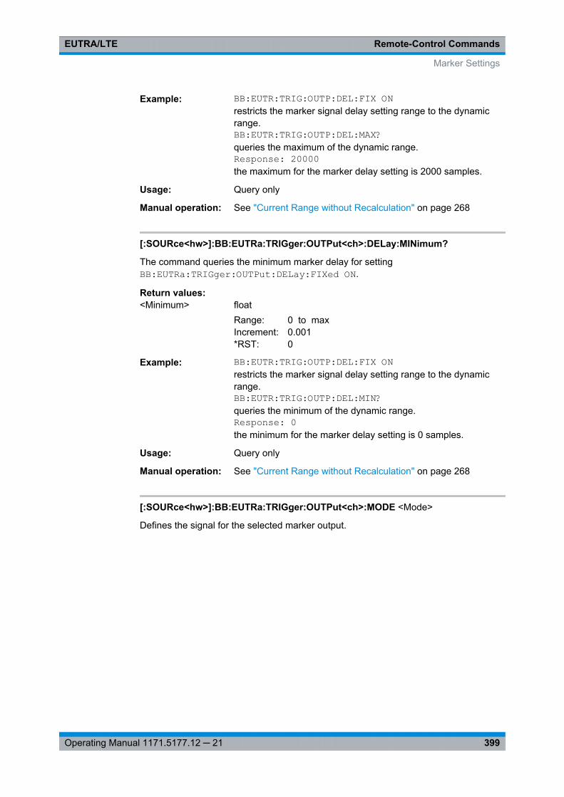
Remote-Control CommandsEUTRA/LTE
399Operating Manual 1171.5177.12 ─ 21
Example: BB:EUTR:TRIG:OUTP:DEL:FIX ONrestricts the marker signal delay setting range to the dynamicrange.BB:EUTR:TRIG:OUTP:DEL:MAX?queries the maximum of the dynamic range.Response: 20000the maximum for the marker delay setting is 2000 samples.
Usage: Query only
Manual operation: See "Current Range without Recalculation" on page 268
[:SOURce<hw>]:BB:EUTRa:TRIGger:OUTPut<ch>:DELay:MINimum?
The command queries the minimum marker delay for settingBB:EUTRa:TRIGger:OUTPut:DELay:FIXed ON.
Return values: <Minimum> float
Range: 0 to maxIncrement: 0.001*RST: 0
Example: BB:EUTR:TRIG:OUTP:DEL:FIX ONrestricts the marker signal delay setting range to the dynamicrange.BB:EUTR:TRIG:OUTP:DEL:MIN?queries the minimum of the dynamic range.Response: 0the minimum for the marker delay setting is 0 samples.
Usage: Query only
Manual operation: See "Current Range without Recalculation" on page 268
[:SOURce<hw>]:BB:EUTRa:TRIGger:OUTPut<ch>:MODE <Mode>
Defines the signal for the selected marker output.
Marker Settings
Remote-Control CommandsEUTRA/LTE
400Operating Manual 1171.5177.12 ─ 21
Parameters:<Mode> SUBFram | FRAM | RESTart | PERiod | RATio | FAP | | INTernal
| | TRIGgerSUBFramA marker signal is generated at the start of each subframe. Therise and fall offsets are defined with the commands [:SOURce<hw>]: BB:EUTRa: TRIGger:OUTPut<ch>: FOFFset and [:SOURce<hw>]: BB: EUTRa:TRIGger: OUTPut<ch>: ROFFset.FAPThe marker signal is high whenever a burst is active and lowduring inactive signal parts (such as the gaps between bursts inuplink mode or the uplink subframe in downlink TDD mode).This marker can be used to decrease the carrier leakage duringinactive signal parts by feeding it into the pulse modulator.FRAMA marker signal is generated at the start of each radio frame.The rise and fall offsets are defined with the commands [:SOURce<hw>]: BB:EUTRa: TRIGger:OUTPut<ch>: FOFFset and [:SOURce<hw>]: BB:EUTRa: TRIGger: OUTPut<ch>: ROFFset .RESTartA marker signal is generated at the start of each ARB sequence.The rise and fall offsets are defined with the commands [:SOURce<hw>]: BB: EUTRa:TRIGger: OUTPut<ch>: FOFFset and [: SOURce<hw>]: BB:EUTRa: TRIGger:OUTPut<ch>: ROFFset .PERiodA marker signal is generated at the beginning of every user-defined period. The period is defined with the command [:SOURce<hw>]: BB:EUTRa: TRIGger:OUTPut<ch>: PERiod on page 401.RATioA marker signal corresponding to the Time Off / Time On specifi-cations in the commands [:SOURce<hw>]: BB:EUTRa: TRIGger:OUTPut<ch>: ONTime and [:SOURce<hw>]: BB:EUTRa:TRIGger: OUTPut<ch>: OFFTime is generated.
INTernalSpecial marker signal for the real time feedback mode (chap-ter 6, "Realtime Feedback for Closed Loop BS Tests",on page 61) or for SFN Restart Period "3GPP (1024 Frames)".TRIGerA received internal or external trigger signal is output at themarker connector.*RST: FRAM
Marker Settings
Remote-Control CommandsEUTRA/LTE
401Operating Manual 1171.5177.12 ─ 21
Example: BB:EUTR:TRIG:OUTP:MODE FRAMeselects the frame marker for the corresponding marker signal.BB:EUTR:TRIG:OUTP:ROFF 20sets a rise offset of 20 samples for the corresponding markersignal.BB:EUTR:TRIG:OUTP:FOFF 2000sets a fall offset of 2000 samples for the corresponding markersignal on path A.
Manual operation: See "Marker Mode" on page 266
[:SOURce<hw>]:BB:EUTRa:TRIGger:OUTPut<ch>:FOFFset <FallOffset>[:SOURce<hw>]:BB:EUTRa:TRIGger:OUTPut<ch>:ROFFset <RiseOffset>
Sets the rise offset for on/off ratio marker in number of samples.
Parameters:<RiseOffset> integer
Range: -64000 samples to 64000 samplesIncrement: 1 sample*RST: 0 samples
Example: BB:EUTR:TRIG:OUTP2:ROFF 20sets a rise offset of 20 samples for marker signal 2.
Manual operation: See "Rise/Fall Offset" on page 267
[:SOURce<hw>]:BB:EUTRa:TRIGger:OUTPut<ch>:OFFTime <OffTime>[:SOURce<hw>]:BB:EUTRa:TRIGger:OUTPut<ch>:ONTime <OnTime>
Sets the number of samples in a period (ON time + OFF time) during which the markersignal in setting BB:EUTR:TRIGger:OUTPut:MODE RATio on the marker outputs isON.
Parameters:<OnTime> integer
Range: 1 sample to 2^24-1 samplesIncrement: 1 sample*RST: 1 sample
Example: BB:EUTR:TRIG:OUTP:MODE RATselects the ratio marker for the corresponding marker signal.BB:EUTR:TRIG:OUTP:ONT 200sets an ON time of 200 samples for the corresponding markersignal.
Manual operation: See "Marker Mode" on page 266
[:SOURce<hw>]:BB:EUTRa:TRIGger:OUTPut<ch>:PERiod <Period>
Sets the repetition rate for the signal at the marker outputs, expressed in terms of sam-ples. The setting is only valid for selection "USER" in BB:EUTR:TRIG:OUTP:MODE.
Marker Settings
Remote-Control CommandsEUTRA/LTE
402Operating Manual 1171.5177.12 ─ 21
Parameters:<Period> unsigned integer
Range: 1 sample to 2^32-1 samplesIncrement: 1 sample*RST: 2 samples
Example: BB:EUTR:TRIG:OUTP2:MODE PERselects the user marker for the corresponding marker signal.BB:EUTR:TRIG:OUTP2:PER 1600sets a period of 1600 samples, i.e. the marker signal is repeatedevery 1600th sample.
Manual operation: See "Marker Mode" on page 266
9.7 General EUTRA/LTE Settings
[:SOURce<hw>]:BB:EUTRa:TDD:SPSConf...................................................................... 402[:SOURce<hw>]:BB:EUTRa:TDD:UDConf........................................................................ 402
[:SOURce<hw>]:BB:EUTRa:TDD:SPSConf <SpecSubfrConf>
(enabled for TDD duplexing mode only)
Sets the Special Subframe Configuration number, i.e. together with the parameter [: SOURce<hw>]: BB:EUTRa: DL:CPC defines the lengths of the DwPTS, the GuardPeriod and the UpPTS.
Parameters:<SpecSubfrConf> integer
Range: 0 to 8Increment: 1*RST: 0
Example: SOURce1:BB:EUTRa:TDD:SPSConf 2sets the special subframe configuration
Manual operation: See "Configuration of Special Subframes" on page 117
[:SOURce<hw>]:BB:EUTRa:TDD:UDConf <ULDLConf>
(enabled for TDD duplexing mode only)
Sets the Uplink-Downlink Configuration number, i.e. defines which subframe is usedfor downlink respectively uplink, and where the special subframes are located.
Parameters:<ULDLConf> integer
Range: 0 to 6Increment: 1*RST: 0
General EUTRA/LTE Settings
Remote-Control CommandsEUTRA/LTE
403Operating Manual 1171.5177.12 ─ 21
Example: BB:EUTR:TDD:UDC 2sets the UL/DL configuration
Manual operation: See "UL/DL Configuration" on page 116
9.8 General EUTRA/LTE Downlink Settings
[:SOURce<hw>]:BB:EUTRa:DL:CONF:MODE.................................................................. 404[:SOURce<hw>]:BB:EUTRa:DL:MIMO:CONFiguration.......................................................404[:SOURce<hw>]:BB:EUTRa:DL:MIMO:ANTenna...............................................................404[:SOURce<hw>]:BB:EUTRa:DL:MIMO:ANTA....................................................................405[:SOURce<hw>]:BB:EUTRa:DL:MIMO:ANTB....................................................................405[:SOURce<hw>]:BB:EUTRa:DL:MIMO:APM:CS:AP<dir0>:BB<st0>:REAL...........................405[:SOURce<hw>]:BB:EUTRa:DL:MIMO:APM:CS:AP<dir0>:BB<st0>:IMAGinary.................... 405[:SOURce<hw>]:BB:EUTRa:DL:MIMO:APM:MAPCoordinates............................................ 406[:SOURce<hw>]:BB:EUTRa:DL:REFSig:POWer............................................................... 406[:SOURce<hw>]:BB:EUTRa:DL:REFSig:EPRE................................................................. 406[:SOURce<hw>]:BB:EUTRa:DL:SYNC:TXANtenna............................................................407[:SOURce<hw>]:BB:EUTRa:DL:SYNC:PPOWer............................................................... 407[:SOURce<hw>]:BB:EUTRa:DL:SYNC:SPOWer............................................................... 407[:SOURce<hw>]:BB:EUTRa:DL:BW.................................................................................407[:SOURce<hw>]:BB:EUTRa:DL:NORB.............................................................................408[:SOURce<hw>]:BB:EUTRa:DL:SRATe?..........................................................................408[:SOURce<hw>]:BB:EUTRa:DL:FFT................................................................................ 408[:SOURce<hw>]:BB:EUTRa:DL:OCCBandwidth?.............................................................. 409[:SOURce<hw>]:BB:EUTRa:DL:OCCSubcarriers?.............................................................409[:SOURce<hw>]:BB:EUTRa:DL:LGS?..............................................................................409[:SOURce<hw>]:BB:EUTRa:DL:RGS?............................................................................. 410[:SOURce<hw>]:BB:EUTRa:DL[:PLCI]:CID.......................................................................410[:SOURce<hw>]:BB:EUTRa:DL[:PLCI]:CIDGroup..............................................................410[:SOURce<hw>]:BB:EUTRa:DL[:PLCI]:PLID..................................................................... 411[:SOURce<hw>]:BB:EUTRa:DL:CSETtings:RARNti...........................................................411[:SOURce<hw>]:BB:EUTRa:DL:CPC............................................................................... 411[:SOURce<hw>]:BB:EUTRa:DL:ULCPc............................................................................412[:SOURce<hw>]:BB:EUTRa:DL:PBCH:RATBa..................................................................412[:SOURce<hw>]:BB:EUTRa:DL:PDCCh:RATBa................................................................412[:SOURce<hw>]:BB:EUTRa:DL:PDSCh:PB...................................................................... 413[:SOURce<hw>]:BB:EUTRa:DL:PDSCh:RATBa................................................................ 413[:SOURce<hw>]:BB:EUTRa:DL:PHICh:DURation..............................................................413[:SOURce<hw>]:BB:EUTRa:DL:PHICh:NGParameter........................................................414[:SOURce<hw>]:BB:EUTRa:DL:PRSS:BW....................................................................... 414[:SOURce<hw>]:BB:EUTRa:DL:PRSS:CI......................................................................... 415[:SOURce<hw>]:BB:EUTRa:DL:PRSS:DPRS?..................................................................415[:SOURce<hw>]:BB:EUTRa:DL:PRSS:NPRS................................................................... 415[:SOURce<hw>]:BB:EUTRa:DL:PRSS:POW.....................................................................415[:SOURce<hw>]:BB:EUTRa:DL:PRSS:STATe.................................................................. 416[:SOURce<hw>]:BB:EUTRa:DL:PRSS:TPRS?.................................................................. 416[:SOURce<hw>]:BB:EUTRa:DL:PRSS:MIPattern.............................................................. 416
General EUTRA/LTE Downlink Settings
Remote-Control CommandsEUTRA/LTE
404Operating Manual 1171.5177.12 ─ 21
[:SOURce<hw>]:BB:EUTRa:DL:CONF:MODE <Scheduling>
Determines whether the configuration and scheduling of the different PDSCH alloca-tions inside of the DL allocation table is performed manually or according to the config-uration made for the DCIs.
Parameters:<Scheduling> MANual | AUTO
MANualNo cross-reference between the settings made for the PDCCHDCIs and the PDSCHs settings. Configure the PDSCH alloca-tions manually.AUTOPrecoding for spatial multiplexing according to 3GPP TS 36.211and the selected parameters.*RST: MANual
Example: BB:EUTR:DL:CONF:MODE AUTOenables the generation of 3GPP compliant EUTRA/LTE signaland the PDSCH allocations are configured automatically accord-ing to the configuration of the PDCCH DCIs.
Manual operation: See "PDSCH Scheduling" on page 117
[:SOURce<hw>]:BB:EUTRa:DL:MIMO:CONFiguration <Configuration>
Sets the global MIMO configuration.
Parameters:<Configuration> TX1 | TX2 | TX4 | SIBF
*RST: TX1
Example: BB:EUTR:DL:MIMO:CONF TX2sets the MIMO configuration to 2 TxAntennas.
Manual operation: See "Global MIMO Configuration" on page 118
[:SOURce<hw>]:BB:EUTRa:DL:MIMO:ANTenna <Antenna>
Queries the simulated antenna.
This command is allowed for simulation mode set to 1 Tx Antenna only.
Parameters:<Antenna> ANT1 | ANT2 | ANT3 | ANT4
*RST: ANT1
Example: BB:EUTR:DL:MIMO:CONF TX1sets 1 TxAntenna simulation mode.BB:EUTR:DL:MIMO:ANT?queries the simulated antenna.Response: ANT1
General EUTRA/LTE Downlink Settings
Remote-Control CommandsEUTRA/LTE
405Operating Manual 1171.5177.12 ─ 21
Manual operation: See "Simulated Antenna" on page 119
[:SOURce<hw>]:BB:EUTRa:DL:MIMO:ANTA <AntennaA>
Sets the simulated antenna for path A. The available selections depend on the currentMIMO configuration.
Parameters:<AntennaA> ANT1 | ANT2 | ANT3 | ANT4 | NONE | ALL
*RST: ANT1
Example: BB:EUTR:DL:MIMO:CONF TX2sets the MIMO configuration to 2 TxAntennas.BB:EUTR:DL:MIMO:ANTA ANT2sets the configuration to antenna 2.
Manual operation: See "Simulated Antenna Path A" on page 119
[:SOURce<hw>]:BB:EUTRa:DL:MIMO:ANTB <AntennaB>
Sets the simulated antenna for path B. The available selections depend on the currentMIMO configuration.
Parameters:<AntennaB> NONE | ANT1 | ANT2 | ANT3 | ANT4
*RST: NONE
Example: BB:EUTR:DL:MIMO:CONF TX4sets the MIMO configuration to 2 TxAntennas.BB:EUTR:DL:MIMO:ANTB ANT3sets the configuration to antenna 3.
Manual operation: See "Simulated Antenna Path B" on page 119
[:SOURce<hw>]:BB:EUTRa:DL:MIMO:APM:CS:AP<dir0>:BB<st0>:REAL<AntPortMapDat>
[:SOURce<hw>]:BB:EUTRa:DL:MIMO:APM:CS:AP<dir0>:BB<st0>:IMAGinary<AntPortMapDat>
These commands define the mapping of the antenna ports to the physical antennas/basebands.
Suffix: <dir0>
.0 | 1 | 2 | 3 | 4 | 6 | 15 | .. 22antenna portThe mapping of AP0 to AP3 to the BB1 to BB4 is fixed.
<st0> 1 to 4available basebands
General EUTRA/LTE Downlink Settings
Remote-Control CommandsEUTRA/LTE
406Operating Manual 1171.5177.12 ─ 21
Parameters:<AntPortMapDat> float
Range: -1 to 1Increment: 0.01*RST: 0
Manual operation: See "Mapping table" on page 184
[:SOURce<hw>]:BB:EUTRa:DL:MIMO:APM:MAPCoordinates <Type>
Switches between the Cartesian (Real/Imag.) and Cylindrical (Magn./Phase) coordi-nates representation.
Parameters:<Type> CARTesian | CYLindrical
*RST: CART
Options: R&S SMx/AMU-K84/-K284
Manual operation: See "Mapping Coordinates" on page 184
[:SOURce<hw>]:BB:EUTRa:DL:REFSig:POWer <Power>
Sets the reference signal power.
Parameters:<Power> float
Range: -80.00 dB to 10.00 dBIncrement: 0.001 dB*RST: 0.00 dB
Example: BB:EUTR:DL:REFS:POW -10.00sets the reference signal power to -10.00dB.
Manual operation: See "Reference Signal Power" on page 124
[:SOURce<hw>]:BB:EUTRa:DL:REFSig:EPRE <RelToLevelDispl>
Queries the RS Power per RE relative to Level Display.
Parameters:<RelToLevelDispl> float
Range: -80.00 dB to 10.00 dBIncrement: 0.001 dB*RST: 0.00 dB
Example: BB:EUTR:DL:REFS:EPRE?queries the RS Power per RE relative to Level Display.
Manual operation: See "RS Power per RE relative to Level Display" on page 124
General EUTRA/LTE Downlink Settings
Remote-Control CommandsEUTRA/LTE
407Operating Manual 1171.5177.12 ─ 21
[:SOURce<hw>]:BB:EUTRa:DL:SYNC:TXANtenna <TxAntenna>
Defines on which antenna port the P-/S-SYNC is transmitted.
The available values depend on the number of configured antennas.
Parameters:<TxAntenna> ANT1 | ANT2 | ANT3 | ANT4 | NONE | ALL
*RST: ALL
Example: BB:EUTR:DL:SYNC:TXAN ALLenables all antenna ports to transmit P-/S-SYNC
Manual operation: See "P-/S-SYNC Tx Antenna" on page 124
[:SOURce<hw>]:BB:EUTRa:DL:SYNC:PPOWer <PPower>
Sets the power of the primary synchronization signal (P-SYNC).
Parameters:<PPower> float
Range: -80.00 dB to 10.00 dBIncrement: 0.001 dB*RST: 0 dB
Example: BB:EUTR:DL:SYNC:PPOWer -10.00sets the P-SYNC power to -10.00dB.
Manual operation: See "P-SYNC Power" on page 124
[:SOURce<hw>]:BB:EUTRa:DL:SYNC:SPOWer <SPower>
Sets the power of the secondary synchronization signal (S-SYNC).
Parameters:<SPower> float
Range: -80.00 dB to 10.00 dBIncrement: 0.001 dB*RST: 0 dB
Example: BB:EUTR:DL:SYNC:SPOWer -10.00sets the S-SYNC power to -10.00dB.
Manual operation: See "S-SYNC Power" on page 124
[:SOURce<hw>]:BB:EUTRa:DL:BW <Bw>
Sets the DL channel bandwidth.
Parameters:<Bw> USER | BW1_40 | BW3_00 | BW5_00 | BW10_00 | BW15_00 |
BW20_00*RST: BW10_00
General EUTRA/LTE Downlink Settings
Remote-Control CommandsEUTRA/LTE
408Operating Manual 1171.5177.12 ─ 21
Example: BB:EUTR:DL:BW BW20_00Manual operation: See "Channel Bandwidth" on page 114
[:SOURce<hw>]:BB:EUTRa:DL:NORB <Norb>
Selects the number of physical resource blocks per slot.
Parameters:<Norb> integer
Range: 6 to 110Increment: 1*RST: 50
Example: BB:EUTR:DL:BW USERsets the bandwidth mode to USER in downlink.BB:EUTR:DL:NORB 7sets the number of resource blocks to 7.
Manual operation: See "Number of Resource Blocks Per Slot" on page 115
[:SOURce<hw>]:BB:EUTRa:DL:SRATe?
Queries the sampling rate. The value for the sampling rate is set automatically accord-ing to the selected number of resource blocks per slot.
Return values: <SampleRate> float
Range: 1.92 MHz to 30.72 MHzIncrement: 0.001 MHz*RST: 15.36 MHz
Example: BB:EUTR:DL:SRAT?queries the automatically set sampling rate.
Usage: Query only
Manual operation: See "Sampling Rate" on page 116
[:SOURce<hw>]:BB:EUTRa:DL:FFT <Fft>
Sets the FFT (Fast Fourier Transformation) size. The available values depend on theselected number of resource blocks per slot.
Parameters:<Fft> integer
Range: 128 to 2048*RST: 1024
Example: BB:EUTR:DL:FFT?Queries the automatically set fast Fourier transformation param-eter.
General EUTRA/LTE Downlink Settings
Remote-Control CommandsEUTRA/LTE
409Operating Manual 1171.5177.12 ─ 21
Manual operation: See "FFT Size" on page 115
[:SOURce<hw>]:BB:EUTRa:DL:OCCBandwidth?
Queries the of occupied bandwidth. This value is set automatically according to theselected number of resource blocks per slot.
Return values: <OccupBandwidth> float
Range: 1.095 MHz to 19.815 MHz*RST: 9.015 MHz
Example: BB:EUTR:DL:OCCB?queries the automatically set occupied bandwidth in downlink.
Usage: Query only
Manual operation: See "Occupied Bandwidth" on page 115
[:SOURce<hw>]:BB:EUTRa:DL:OCCSubcarriers?
Queries the occupied subcarriers. The value is set automatically according to theselected number of physical resource blocks.
Return values: <OccupSubcarr> integer
Range: 72 to 1321*RST: 601
Example: BB:EUTR:DL:OCCS?queries the number of occupied subcarriers.
Usage: Query only
Manual operation: See "Number Of Occupied Subcarriers" on page 116
[:SOURce<hw>]:BB:EUTRa:DL:LGS?
Queries the number of left guard subcarriers. The value is set automatically accordingto the selected number of physical resource blocks.
Return values: <Lgs> integer
Range: 28 to 364*RST: 212
Example: BB:EUTR:DL:LGS?queries the number of left guard subcarriers.
Usage: Query only
Manual operation: See "Number Of Left Guard Subcarriers" on page 116
General EUTRA/LTE Downlink Settings
Remote-Control CommandsEUTRA/LTE
410Operating Manual 1171.5177.12 ─ 21
[:SOURce<hw>]:BB:EUTRa:DL:RGS?
Queries the number of right guard subcarriers. The value is set automatically accordingto the selected channel bandwidth and the number of physical resource blocks.
Return values: <Rgs> integer
Range: 27 to 364*RST: 211
Example: BB:EUTR:DL:RGS?queries the number of right guard subcarriers.
Usage: Query only
Manual operation: See "Number Of Right Guard Subcarriers" on page 116
[:SOURce<hw>]:BB:EUTRa:DL[:PLCI]:CID <CellId>
Sets the cell identity.
There are 504 unique physical layer cell identities (Cell ID), grouped into 168 uniquephysical cell identity groups that contain three unique identities each. The Cell ID iscalculated as following:
Cell ID = 3*Physical Cell ID Group + Physical Layer ID,
where Physical Cell ID Group is set with the command [:SOURce<hw>]: BB: EUTRa:DL[: PLCI]:CIDGroup and Physical Layer ID with the command [:SOURce<hw>]: BB:EUTRa: DL[:PLCI]: PLID respectively.
Parameters:<CellId> float
Range: 0 to 503Increment: 1*RST: 0
Example: BB:EUTR:DL:PLC:CID 100sets the Cell ID.
Manual operation: See "Cell ID" on page 120
[:SOURce<hw>]:BB:EUTRa:DL[:PLCI]:CIDGroup <CellIdGroup>
Sets the ID of the physical cell identity group.
There are 504 unique physical layer cell identities, grouped into 168 uniquie physicalcell identity groups that contain three unique identities each.
To configure these identities, use the command [:SOURce<hw>]: BB:EUTRa:DL[: PLCI]:PLID .
General EUTRA/LTE Downlink Settings
Remote-Control CommandsEUTRA/LTE
411Operating Manual 1171.5177.12 ─ 21
Parameters:<CellIdGroup> integer
Range: 0 to 167Increment: 1*RST: 0
Example: BB:EUTR:DL:PLC:CIDG 100sets the ID of the physical cell identity group.
Manual operation: See "Physical Cell ID Group" on page 120
[:SOURce<hw>]:BB:EUTRa:DL[:PLCI]:PLID <PhysLayId>
Sets the identity of the physical layer within the selected physical cell identity group,set with the command [:SOURce<hw>]: BB: EUTRa:DL[: PLCI]:CIDGroup .
Parameters:<PhysLayId> integer
Range: 0 to 2Increment: 1*RST: 0
Example: BB:EUTR:DL:PLC:PLID 2sets the identity of the physical layer.
Manual operation: See "Physical Layer ID" on page 121
[:SOURce<hw>]:BB:EUTRa:DL:CSETtings:RARNti <RaRnti>
Sets the random-access response identity RA-RNTI.
The value selected here determines the value of the parameter "UE_ID/n_RNTI" incase a RA_RNTI "User" is selected.
Parameters:<RaRnti> integer
Range: 1 to 60Increment: 1*RST: 1
Example: BB:EUTR:DL:PLC:CSET:RARN 5sets the RA-RNTI
Manual operation: See "RA_RNTI" on page 123
[:SOURce<hw>]:BB:EUTRa:DL:CPC <CyclicPrefix>
Sets the cyclic prefix length for all subframes.
Parameters:<CyclicPrefix> NORMal | EXTended | USER
*RST: NORM
General EUTRA/LTE Downlink Settings
Remote-Control CommandsEUTRA/LTE
412Operating Manual 1171.5177.12 ─ 21
Example: BB:EUTR:DL:CPC NORMa normal prefix is used in all subframes in downlink.BB:EUTR:DL:CPC USERthe cyclic prefix has to be adjusted on subframe basis.BB:EUTR:DL:SUBF6:CYCP NORMa normal prefix is used in subframe 6 in downlink.BB:EUTR:DL:SUBF1:CYCP EXTan extended prefix is used in subframe 1 in downlink.
Manual operation: See "Cyclic Prefix (General DL Settings)" on page 121
[:SOURce<hw>]:BB:EUTRa:DL:ULCPc <GSCpcOppDir>
In TDD duplexing mode, sets the cyclic prefix for the opposite direction.
Parameters:<GSCpcOppDir> NORMal | EXTended
*RST: NORM
Example: :SOURce1:BB:EUTRa:DUPLexing TDD:SOURce1:BB:EUTRa:DL:ULCPc EXTended
Manual operation: See "UL/DL Cyclic Prefix" on page 121
[:SOURce<hw>]:BB:EUTRa:DL:PBCH:RATBa <RatioPbPa>
Sets the transmit energy ratio among the resource elements allocated for PBCH in theOFDM symbols containing reference signal (P_B) and such not containing one (P_A).
Parameters:<RatioPbPa> float
Range: -10.00 to 10.00Increment: 0.001*RST: 0Default unit: dB
Example: BB:EUTR:DL:PBCH:RATB -5.0sets the transmit energie ratio
Manual operation: See "PBCH Ratio rho_B/rho_A" on page 122
[:SOURce<hw>]:BB:EUTRa:DL:PDCCh:RATBa <RatioPbBa>
Sets the transmit energy ratio among the resource elements allocated for PDCCH inthe OFDM symbols containing reference signal (P_B) and such not containing one(P_A).
Parameters:<RatioPbBa> float
Range: -10.00 dB to 10.00 dBIncrement: 0.001*RST: 0 dB
General EUTRA/LTE Downlink Settings
Remote-Control CommandsEUTRA/LTE
413Operating Manual 1171.5177.12 ─ 21
Example: BB:EUTR:DL:PDCC:RATB -5.0sets the transmit energie ratio
Manual operation: See "PDCCH Ratio rho_B/rho_A" on page 122
[:SOURce<hw>]:BB:EUTRa:DL:PDSCh:PB <Pb>
Sets the parameter PDSCH P_B and defines the cell-specific ratio rho_B/rho_Aaccording to 3GPP TS 36.213, Table 5.2-1.
Parameters:<Pb> integer
Range: 0 to 3Increment: 1*RST: 0
Example: BB:EUTR:DL:PDSC:PB 1sets the parameter PDSCH P_B
Manual operation: See "PDSCH P_B" on page 121
[:SOURce<hw>]:BB:EUTRa:DL:PDSCh:RATBa <RatioPbPa>
Sets the transmit energy ratio among the resource elements allocated for PDSCH inthe OFDM symbols containing reference signal (P_B) and such not containing one(P_A).
Parameters:<RatioPbPa> float
Range: -10.00 dB to 10.00 dBIncrement: 0.001*RST: 0 dB
Example: BB:EUTR:DL:PDSC:RATB -5.0sets the transmit energie ratio
Manual operation: See "PDSCH Ratio rho_B/rho_A" on page 122
[:SOURce<hw>]:BB:EUTRa:DL:PHICh:DURation <Duration>
Sets the PHICH duration, i.e. the allocation of the PHICH resource element groupsover the OFDM symbols.
The value selected puts the lower limit of the size of the Control Region for PUCCH([:SOURce<hw>]: BB: EUTRa:DL[: SUBF<st0>]: ENCC:PCFich: CREGion ) that issignaled by the PCFICH.
General EUTRA/LTE Downlink Settings
Remote-Control CommandsEUTRA/LTE
414Operating Manual 1171.5177.12 ─ 21
Parameters:<Duration> NORMal | EXTended
NORMalAll ressource element groups of PHICH ([:SOURce<hw>]: BB:EUTRa: DL[:SUBF<st0>]: ENCC: PHICh:NOGRoups ) are allo-cated on the first OFDM symbol (OFDM Symbol 0).EXTendedThe ressource element groups of PHICH are distributed overthree OFDM symbol (OFDM Symbols 0 .. 2).*RST: NORMal
Example: BB:EUTR:DL:PHIC:DUR NORMsets PHICH normal duration
Manual operation: See "PHICH Duration" on page 122
[:SOURce<hw>]:BB:EUTRa:DL:PHICh:NGParameter <NgParameter>
Sets the parameter N_g according to 3GPP TS 36.211, section 6.9 or enables theselection of user-defined value for the parameter "Number of PHICH Groups" (com-mand [: SOURce<hw>]: BB:EUTRa: DL[:SUBF<st0>]: ENCC: PHICh:NOGRoups on page 471).
Parameters:<NgParameter> NG1_6 | NG1_2 | NG1 | NG2 | NGCustom
NG1_6 | NG1_2 | NG1 | NG2the actual "Number of PHICH Groups" for the different sub-frames is calculated according to 3GPP TS 36.211, section 6.9.NGCustomenables the selection of user-defined value for the parameter"Number of PHICH Groups".*RST: NG1_6
Example: BB:EUTR:DL:PHIC:NGP NG1_2sets PHICH N_g
Manual operation: See "PHICH N_g" on page 122
[:SOURce<hw>]:BB:EUTRa:DL:PRSS:BW <PrsBandwidth>
Defines the bandwidth in which the PRS is transmitted.
Parameters:<PrsBandwidth> BW1_40 | BW3_00 | BW5_00 | BW10_00 | BW15_00 |
BW20_00*RST: BW10_00
Example: BB:EUTR:DL:PRSS:BW BW1_40Sets the bandwidth in which the PRS is transmitted to 1.4 MHz.
Options: R&S SMx/AMU-K84/-K284
General EUTRA/LTE Downlink Settings
Remote-Control CommandsEUTRA/LTE
415Operating Manual 1171.5177.12 ─ 21
Manual operation: See "PRS Bandwidth" on page 129
[:SOURce<hw>]:BB:EUTRa:DL:PRSS:CI <ConfIdx>
Sets the PRS Configuration Index IPRS as defined in 3GPP TS 36.211, table 6.10.4.3-1.
Parameters:<ConfIdx> integer
Range: 0 to 2399Increment: 1*RST: 0
Options: R&S SMx/AMU-K84/-K284
Manual operation: See "PRS Configuration Index" on page 128
[:SOURce<hw>]:BB:EUTRa:DL:PRSS:DPRS?
Queries the subframe offset of the PRS generation (DeltaPRS) as defined in 3GPP TS36.211, table 6.10.4.3-1.
Return values: <DeltaPRS> integer
Range: 0 to 1279Increment: 1*RST: 0
Usage: Query only
Options: R&S SMx/AMU-K84/-K284
Manual operation: See "PRS Subframe offset Delta_PRS" on page 128
[:SOURce<hw>]:BB:EUTRa:DL:PRSS:NPRS <NumberPRS>
Defines the number of consecutive DL subframes in that PRS are transmitted.
Parameters:<NumberPRS> integer
Range: 1 to 6*RST: 1
Options: R&S SMx/AMU-K84/-K284
Manual operation: See "Number of PRS DL Subframes (N_PRS)" on page 129
[:SOURce<hw>]:BB:EUTRa:DL:PRSS:POW <PrsPower>
Sets the power of a PRS resource element relative to the power of a common refer-ence signal resource element.
General EUTRA/LTE Downlink Settings
Remote-Control CommandsEUTRA/LTE
416Operating Manual 1171.5177.12 ─ 21
Parameters:<PrsPower> float
Range: -80.000 to 10.000Increment: 0.001*RST: 0
Options: R&S SMx/AMU-K84/-K284
Manual operation: See "PRS Power" on page 129
[:SOURce<hw>]:BB:EUTRa:DL:PRSS:STATe <PrsState>
Enables the generation of the PRS.
Parameters:<PrsState> 0 | 1 | OFF | ON
*RST: OFF
Options: R&S SMx/AMU-K84/-K284
Manual operation: See "PRS State" on page 128
[:SOURce<hw>]:BB:EUTRa:DL:PRSS:TPRS? <PeriodicityTPRS>
Queries the periodicity of the PRS generation (TPRS) as defined in 3GPP TS 36.211,table 6.10.4.3-1.
Parameters:<PeriodicityTPRS> integer
Range: 160 to 1280*RST: 160
Usage: Query only
Options: R&S SMx/AMU-K84/-K284
Manual operation: See "PRS Periodicity T_PRS" on page 128
[:SOURce<hw>]:BB:EUTRa:DL:PRSS:MIPattern <PrsMutingInfo>
Specifies a bit pattern that defines the muted and not muted PRS.
Parameters:<PrsMutingInfo> bit pattern in hex format; 2, 4, 8 or 16 bit long
each bit defines the PRS state of one PRS occasion0PRS is muted1PRS is transmitted
Example: SOURce1:BB:EUTRa:DL:PRSS:MIPattern #H1,2muts the first PRS occasion
General EUTRA/LTE Downlink Settings
Remote-Control CommandsEUTRA/LTE
417Operating Manual 1171.5177.12 ─ 21
Manual operation: See "PRS Muting Info" on page 129
9.9 General EUTRA/LTE Uplink Settings
[:SOURce<hw>]:BB:EUTRa:UL:BW.................................................................................417[:SOURce<hw>]:BB:EUTRa:UL:NORB.............................................................................418[:SOURce<hw>]:BB:EUTRa:UL:SRATe............................................................................418[:SOURce<hw>]:BB:EUTRa:UL:FFT................................................................................ 418[:SOURce<hw>]:BB:EUTRa:UL:OCCBandwidth?.............................................................. 419[:SOURce<hw>]:BB:EUTRa:UL:OCCSubcarriers?.............................................................419[:SOURce<hw>]:BB:EUTRa:UL:LGS?..............................................................................419[:SOURce<hw>]:BB:EUTRa:UL:RGS?............................................................................. 420[:SOURce<hw>]:BB:EUTRa:UL[:PLCI]:CID.......................................................................420[:SOURce<hw>]:BB:EUTRa:UL[:PLCI]:CIDGroup..............................................................420[:SOURce<hw>]:BB:EUTRa:UL[:PLCI]:PLID..................................................................... 421[:SOURce<hw>]:BB:EUTRa:UL:CPC............................................................................... 421[:SOURce<hw>]:BB:EUTRa:UL:DLCPc............................................................................421[:SOURce<hw>]:BB:EUTRa:UL:SOFFset......................................................................... 422[:SOURce<hw>]:BB:EUTRa:UL:REFSig:GRPHopping....................................................... 422[:SOURce<hw>]:BB:EUTRa:UL:REFSig:SEQHopping....................................................... 422[:SOURce<hw>]:BB:EUTRa:UL:REFSig:DSSHift...............................................................422[:SOURce<hw>]:BB:EUTRa:UL:REFSig:DMRS.................................................................423[:SOURce<hw>]:BB:EUTRa:UL:REFSig:SRS:ANSTx........................................................ 423[:SOURce<hw>]:BB:EUTRa:UL:REFSig:SRS:MUPTs........................................................423[:SOURce<hw>]:BB:EUTRa:UL:REFSig:SRS:CSRS..........................................................424[:SOURce<hw>]:BB:EUTRa:UL:REFSig:SRS:DSFC?........................................................424[:SOURce<hw>]:BB:EUTRa:UL:REFSig:SRS:SUConfiguration...........................................424[:SOURce<hw>]:BB:EUTRa:UL:REFSig:SRS:TSFC?........................................................ 425[:SOURce<hw>]:BB:EUTRa:UL:PRACh:CONFiguration.....................................................425[:SOURce<hw>]:BB:EUTRa:UL:PRACh:FOFFset..............................................................425[:SOURce<hw>]:BB:EUTRa:UL:PRACh:RSET..................................................................426[:SOURce<hw>]:BB:EUTRa:UL:PUSCh:FHMode.............................................................. 426[:SOURce<hw>]:BB:EUTRa:UL:PUSCh:FHOFfset............................................................ 426[:SOURce<hw>]:BB:EUTRa:UL:PUSCh:NOSM.................................................................427[:SOURce<hw>]:BB:EUTRa:UL:PUCCh:NORB.................................................................427[:SOURce<hw>]:BB:EUTRa:UL:PUCCh:DESHift...............................................................427[:SOURce<hw>]:BB:EUTRa:UL:PUCCh:N1CS..................................................................428[:SOURce<hw>]:BB:EUTRa:UL:PUCCh:N2RB..................................................................428[:SOURce<hw>]:BB:EUTRa:UL:PUCCh:N1NMax..............................................................428[:SOURce<hw>]:BB:EUTRa:UL:PUCCh:N1EMax..............................................................429[:SOURce<hw>]:BB:EUTRa:UL:PUCCh:N2Max................................................................ 429[:SOURce<hw>]:BB:EUTRa:UL:PUCCh:N3Max................................................................ 430
[:SOURce<hw>]:BB:EUTRa:UL:BW <BandWidth>
Sets the UL channel bandwidth.
General EUTRA/LTE Uplink Settings
Remote-Control CommandsEUTRA/LTE
418Operating Manual 1171.5177.12 ─ 21
Parameters:<BandWidth> USER | BW1_40 | BW3_00 | BW5_00 | BW10_00 | BW15_00 |
BW20_00*RST: BW10_00
Example: BB:EUTR:UL:BW BW1_40selects a uplink frequency band of 1.4 MHz.
Manual operation: See "Channel Bandwidth (UL)" on page 195
[:SOURce<hw>]:BB:EUTRa:UL:NORB <NumResBlocks>
Selects the number of physical resource blocks per slot.
Parameters:<NumResBlocks> integer
Range: 6 to 110Increment: 1*RST: 50
Example: BB:EUTR:UL:BW USERsets the bandwidth mode to USER in downlink.BB:EUTR:UL:NORB 7sets the number of resource blocks to 7.
Manual operation: See "Number of Resource Blocks Per Slot (UL)" on page 195
[:SOURce<hw>]:BB:EUTRa:UL:SRATe <SampRate>
Queries the sampling rate. The value for the sampling rate is set automatically accord-ing to the selected number of resource blocks per slot.
Parameters:<SampRate> float
Range: 1.92 MHz to 30.72 MHzIncrement: 0.001 MHz*RST: 15.36 MHz
Example: BB:EUTR:UL:SRAT?queries the automatically set sampling rate.
Manual operation: See "Sampling Rate (UL)" on page 196
[:SOURce<hw>]:BB:EUTRa:UL:FFT <FftSize>
Sets the FFT (Fast Fourier Transformation) size. The available values depend on theselected number of resource blocks per slot.
Parameters:<FftSize> integer
Range: 128 to 2048*RST: 1024
General EUTRA/LTE Uplink Settings
Remote-Control CommandsEUTRA/LTE
419Operating Manual 1171.5177.12 ─ 21
Example: BB:EUTR:UL:FFT?queries the automatically set FFT size.
Manual operation: See "FFT Size (UL)" on page 195
[:SOURce<hw>]:BB:EUTRa:UL:OCCBandwidth?
Queries the occupied bandwidth. This value is set automatically according to theselected number of resource blocks per slot.
Return values: <OccBandwidth> float
Range: 1.080 to 19.800*RST: 9.000Default unit: MHz
Example: BB:EUTR:UL:OCCB?queries the automatically set occupied bandwidth in uplink.
Usage: Query only
Manual operation: See "Occupied Bandwidth (UL)" on page 196
[:SOURce<hw>]:BB:EUTRa:UL:OCCSubcarriers?
Queries the occupied subcarriers. The value is set automatically according to theselected number of resource blocks per slot.
Return values: <OccSubcarriers> integer
Range: 72 to 1320*RST: 600
Example: BB:EUTR:UL:OCCS?queries the number of occupied subcarriers.
Usage: Query only
Manual operation: See "Number Of Occupied Subcarriers (UL)" on page 196
[:SOURce<hw>]:BB:EUTRa:UL:LGS?
Queries the number of left guard subcarriers. The value is set automatically accordingto the selected number of resource blocks per slot.
Return values: <LgSubCarr> integer
Range: 28 to 364*RST: 212
Example: BB:EUTR:UL:LGS?queries the number of left guard subcarriers.
Usage: Query only
General EUTRA/LTE Uplink Settings
Remote-Control CommandsEUTRA/LTE
420Operating Manual 1171.5177.12 ─ 21
Manual operation: See "Number Of Left Guard Subcarriers (UL)" on page 196
[:SOURce<hw>]:BB:EUTRa:UL:RGS?
Queries the number of right guard subcarriers. The value is set automatically accordingto the selected number of resource blocks per slot.
Return values: <RgSubCarr> integer
Range: 28 to 364*RST: 212
Example: BB:EUTR:UL:RGS?queries the number of right guard subcarriers.
Usage: Query only
Manual operation: See "Number Of Right Guard Subcarriers (UL)" on page 196
[:SOURce<hw>]:BB:EUTRa:UL[:PLCI]:CID <CellId>
Sets the cell identity.
There are 504 unique physical layer cell identities (Cell ID), grouped into 168 uniquephysical cell identity groups that contain three unique identities each. The Cell ID iscalculated as following:
Cell ID = 3*Physical Cell ID Group + Physical Layer ID,
where Physical Cell ID Group is set with the command [:SOURce<hw>]: BB: EUTRa:UL[: PLCI]:CIDGroup and Physical Layer ID with the command [:SOURce<hw>]: BB:EUTRa: UL[:PLCI]: PLIDrespectively.
Parameters:<CellId> integer
Range: 0 to 503Increment: 1*RST: 0
Example: BB:EUTR:UL:PLC:CID 100sets the Cell ID.
Manual operation: See "Cell ID (UL)" on page 197
[:SOURce<hw>]:BB:EUTRa:UL[:PLCI]:CIDGroup <PhysCellIdGroup>
Sets the ID of the physical cell identity group.
Parameters:<PhysCellIdGroup> integer
Range: 0 to 167Increment: 1*RST: 0
General EUTRA/LTE Uplink Settings
Remote-Control CommandsEUTRA/LTE
421Operating Manual 1171.5177.12 ─ 21
Example: BB:EUTR:UL:PLC:CIDG 100sets the UL physical cell ID group
Manual operation: See "Physical Cell ID Group (UL)" on page 197
[:SOURce<hw>]:BB:EUTRa:UL[:PLCI]:PLID <PhysicalLayerId>
Sets the identity of the physical layer within the selected physical cell identity group,set with the command [:SOURce<hw>]: BB: EUTRa:UL[: PLCI]:CIDGroup .
Parameters:<PhysicalLayerId> integer
Range: 0 to 2Increment: 1*RST: 0
Example: BB:EUTR:UL:PLC:PLID 2sets the UL physical layer ID
Manual operation: See "Physical Layer ID (UL)" on page 198
[:SOURce<hw>]:BB:EUTRa:UL:CPC <CyclicPrefix>
Sets the cyclic prefix length for all subframes.
Parameters:<CyclicPrefix> NORMal | EXTended | USER
*RST: NORM
Example: BB:EUTR:UL:CPC NORMa normal prefix is used in all subframes in uplink.
Example: BB:EUTR:UL:CPC USERthe cyclic prefix has to be adjusted on subframe basis.BB:EUTR:UL:SUBF6:CYCP NORMa normal prefix is used in subframe 6 in uplink.BB:EUTR:UL:SUBF1:CYCP EXTan extended prefix is used in subframe 1 in uplink.
Manual operation: See "Cyclic Prefix (General UL Settings)" on page 198
[:SOURce<hw>]:BB:EUTRa:UL:DLCPc <GSCpcOppDir>
In TDD mode, determines the cyclic prefix for the appropriate opposite direction.
Parameters:<GSCpcOppDir> NORMal | EXTended
*RST: NORM
Example: :SOURce1:BB:EUTRa:DUPLexing TDD:SOURce1:BB:EUTRa:UL:DLCPc EXTended
Manual operation: See "UL/DL Cyclic Prefix" on page 121
General EUTRA/LTE Uplink Settings
Remote-Control CommandsEUTRA/LTE
422Operating Manual 1171.5177.12 ─ 21
[:SOURce<hw>]:BB:EUTRa:UL:SOFFset <SfnOffset>
Set the start SFN value.
Parameters:<SfnOffset> integer
Range: 0 to 4095Increment: 1*RST: 0Default unit: Frames
Example: :SOURce1:BB:EUTRa:UL:SOFFset 10Sets the SFN start value
Manual operation: See "SFN Offset" on page 198
[:SOURce<hw>]:BB:EUTRa:UL:REFSig:GRPHopping <GroupHopping>
Enables/disables group hopping for the uplink reference signals demodulation refer-ence signal (DRS) and sounding reference signal (SRS).
Parameters:<GroupHopping> 0 | 1 | OFF | ON
*RST: OFF
Example: BB:EUTR:UL:REFS:GRPH ONenables group hopping
Manual operation: See "Group Hopping" on page 198
[:SOURce<hw>]:BB:EUTRa:UL:REFSig:SEQHopping <SequenceHopping>
Enables/disables sequence hopping for the uplink reference signals demodulation ref-erence signal (DRS) and sounding reference signal (SRS).
Parameters:<SequenceHopping> 0 | 1 | OFF | ON
*RST: OFF
Example: BB:EUTR:UL:REFS:SEQH ONenables sequence hopping
Manual operation: See "Sequence Hopping" on page 199
[:SOURce<hw>]:BB:EUTRa:UL:REFSig:DSSHift <DeltaSeqShift>
Sets the delta sequence shift for PUSCH needed for the calculation of the group hop-ping pattern.
General EUTRA/LTE Uplink Settings
Remote-Control CommandsEUTRA/LTE
423Operating Manual 1171.5177.12 ─ 21
Parameters:<DeltaSeqShift> integer
Range: 0 to 29Increment: 1*RST: 0
Example: BB:EUTR:UL:REFS:DSSH 3sets the delta sequence shift for PUSCH
Manual operation: See "Delta Sequence Shift for PUSCH" on page 199
[:SOURce<hw>]:BB:EUTRa:UL:REFSig:DMRS <DrsDmrs>
Sets the part of the demodulation reference signal (DMRS) index which is broadcastedand therefore valid for the whole cell. This index applies when multiple shifts within acell are used and is used by the calculation of the DMRS sequence.
Parameters:<DrsDmrs> integer
Range: 0 to 11Increment: 1*RST: 0
Example: BB:EUTR:UL:REFS:DMRS 4sets the demodulation reference signal index to 4
Manual operation: See "n(1)_DMRS" on page 199
[:SOURce<hw>]:BB:EUTRa:UL:REFSig:SRS:ANSTx <AnSrsSimTxState>
Enables/disables simultaneous transmission of SRS (sounding reference signal) andACK/NACK messages, i.e. transmission of SRS and PUCCH in the same subframe.
Parameters:<AnSrsSimTxState> 0 | 1 | OFF | ON
*RST: OFF
Example: BB:EUTR:UL:REFS:SRS:ANST ONManual operation: See "A/N + SRS simultaneous Tx" on page 205
[:SOURce<hw>]:BB:EUTRa:UL:REFSig:SRS:MUPTs <MaxUpPts>
Enables/disables the cell specific parameter srsMaxUpPts.
If enabled, a SRS transmission in the UpPTS field (TDD) is made only in the frequencyarea that does not overlap with the frequency resources reserved for a possiblePRACH preamble format 4 transmission.
This is done by reconfiguring the number of SRS resource blocks in the special sub-frames, which would otherwise be determined by C_SRS and B_SRS.
General EUTRA/LTE Uplink Settings
Remote-Control CommandsEUTRA/LTE
424Operating Manual 1171.5177.12 ─ 21
Parameters:<MaxUpPts> 0 | 1 | OFF | ON
*RST: OFF
Example: BB:EUTR:UL:REFS:SRS:MUPT ONenables the parameter srsMaxUpPts
Manual operation: See "SRS MaxUpPTS" on page 205
[:SOURce<hw>]:BB:EUTRa:UL:REFSig:SRS:CSRS <Csrs>
Sets the cell specific parameter SRS Bandwidth Configuration (CSRS).
Parameters:<Csrs> integer
Range: 0 to 7Increment: 1*RST: 0
Example: BB:EUTR:UL:REFS:SRS:CSRS 4sets the SRS bandwidth configuration
Manual operation: See "SRS Bandwidth Configuration C_SRS" on page 205
[:SOURce<hw>]:BB:EUTRa:UL:REFSig:SRS:DSFC?
Queries the value for the cell specific parameter transmission offset DeltaSFC in sub-frames, depending on the selected SRS Subframe Configuration ([:SOURce<hw>]: BB:EUTRa: UL:REFSig: SRS:CSRS)and the Duplexing mode ([:SOURce<hw>]: BB: EUTRa:DUPLexing ).
Return values: <DeltSFC> string
Example: BB:EUTR:UL:REFS:SRS:SUC 4sets the SRS configurationBB:EUTR:UL:REFS:SRS:DSFC?queries the Delta_SFC parameter
Usage: Query only
Manual operation: See "Transmission Offset Delta_SFC" on page 205
[:SOURce<hw>]:BB:EUTRa:UL:REFSig:SRS:SUConfiguration <SubFrameConfig>
Sets the cell specific parameter SRS subframe configuration.
Parameters:<SubFrameConfig> integer
Range: 0 to 15Increment: 1*RST: 0
General EUTRA/LTE Uplink Settings
Remote-Control CommandsEUTRA/LTE
425Operating Manual 1171.5177.12 ─ 21
Example: BB:EUTR:UL:REFS:SRS:SUC 4sets the SRS configuration
Manual operation: See "SRS Subframe Configuration" on page 205
[:SOURce<hw>]:BB:EUTRa:UL:REFSig:SRS:TSFC?
Queries the value for the cell specific parameter configuration period TSFC in sub-frames, depending on the selected SRS Subframe Configuration ([:SOURce<hw>]: BB:EUTRa: UL:REFSig: SRS:CSRS )and the Duplexing mode ([:SOURce<hw>]: BB:EUTRa: DUPLexing).
Return values: <Tsfc> string
Example: BB:EUTR:UL:REFS:SRS:SUC 4sets the SRS configurationBB:EUTR:UL:REFS:SRS:TSFC?queries the T_SFC parameter
Usage: Query only
Manual operation: See "Configuration Period T_SFC" on page 205
[:SOURce<hw>]:BB:EUTRa:UL:PRACh:CONFiguration <Configuration>
Sets the PRACH configuration number as defined in the 3GPP TS 36.211, i.e. definesthe time and frequency resources in which random access preamble transmission isallowed.
Parameters:<Configuration> integer
Range: 0 to 63Increment: 1*RST: 0
Example: BB:EUTR:UL:PRAC:CONF 10sets the PRACH configuration
Manual operation: See "PRACH Configuration" on page 200
[:SOURce<hw>]:BB:EUTRa:UL:PRACh:FOFFset <FrequencyOffset>
For preamble formats 0-3, sets the prach-FrequencyOffset nRAPRBoffset as defined in the
3GPP TS 36.211, i.e. determines the first physical resource block available for PRACHexpressed as a physical resource block number that fulfills the equation:
0 <= nRAPRBoffset <= Number of UL Resource Blocks - 6
General EUTRA/LTE Uplink Settings
Remote-Control CommandsEUTRA/LTE
426Operating Manual 1171.5177.12 ─ 21
Parameters:<FrequencyOffset> integer
Range: 0 to 104Increment: 1*RST: 0
Example: BB:EUTR:UL:PRAC:FOFF 2sets the frequency offset
Manual operation: See "PRACH Frequency Offset" on page 199
[:SOURce<hw>]:BB:EUTRa:UL:PRACh:RSET <RestrictedSet>
Enables/disables using of a restricted preamble set.
Parameters:<RestrictedSet> 0 | 1 | OFF | ON
*RST: ON
Example: BB:EUTR:UL:PRAC:RSET ONenables using of restricted set
Manual operation: See "Restricted Set (High Speed Mode)" on page 201
[:SOURce<hw>]:BB:EUTRa:UL:PUSCh:FHMode <FreqHoppingMode>
Sets the frequency hopping mode for PUSCH.
Frequency hopping is applied according to 3GPP TS36.213.
Parameters:<FreqHoppingMode> INTRa | INTer
INTerAn inter subframe hopping is performed.INTRaBoth intra- and inter-subframe subframe hopping are performed.*RST: INTRa
Example: BB:EUTR:UL:PUSC:FHM INTselects inter subframe hopping mode
Manual operation: See "Frequency Hopping Mode" on page 201
[:SOURce<hw>]:BB:EUTRa:UL:PUSCh:FHOFfset <FHoppOffset>
Sets the PUSCH Hopping Offset NRBHO.
The PUSCH Hopping Offset determines the first physical resource block and the maxi-mum number of physical resource blocks available for PUSCH transmission if PUSCHfrequency hopping is used.
General EUTRA/LTE Uplink Settings
Remote-Control CommandsEUTRA/LTE
427Operating Manual 1171.5177.12 ─ 21
Parameters:<FHoppOffset> integer
Range: 0 to maxIncrement: 1*RST: 0
Example: BB:EUTR:UL:PUSC:FHOF 2set the PUSCH hopping offset
Manual operation: See "PUSCH Hopping Offset" on page 202
[:SOURce<hw>]:BB:EUTRa:UL:PUSCh:NOSM <SubBandCount>
Sets the number of sub-bands (Nsb) into that the total range of physical resourceblocks available for PUSCH transmission is devided. The frequency hopping is per-formed at sub-band level.
Parameters:<SubBandCount> integer
Range: 1 to 4Increment: 1*RST: 4
Example: BB:EUTR:UL:PUSC:NOSM 3sets the number of sub-bands
Manual operation: See "Number of Sub-bands" on page 202
[:SOURce<hw>]:BB:EUTRa:UL:PUCCh:NORB <RbCount>
Sets the PUCCH region in terms of reserved resource blocks, located at the edges ofthe channel bandwidth.
Parameters:<RbCount> integer
Range: 0 to 110Increment: 1*RST: 4
Example: BB:EUTR:UL:PUCC:NORB 3reserves 3 RBs for PUCCH
Manual operation: See "Number of RBs used for PUCCH" on page 202
[:SOURce<hw>]:BB:EUTRa:UL:PUCCh:DESHift <DeltaShift>
Sets the delta shift parameter.
General EUTRA/LTE Uplink Settings
Remote-Control CommandsEUTRA/LTE
428Operating Manual 1171.5177.12 ─ 21
Parameters:<DeltaShift> integer
Range: 1 to 3Increment: 1*RST: 2
Example: BB:EUTR:PUCC:DESH 3sets the delta shift parameter
Manual operation: See "Delta Shift" on page 203
[:SOURce<hw>]:BB:EUTRa:UL:PUCCh:N1CS <N1Cs>
Sets the number of cyclic shifts used for PUCCH format 1/1a/1b in a resource blockused for a combination of the formats 1/1a/1b and 2/2a/2b.
Parameters:<N1Cs> integer
Range: 0 to 8Increment: 1*RST: 6
Example: BB:EUTR:UL:PUCC:N1CS 55 cyclic shifts will be used for PUCCH format 1/1a/1b in a RBused for a combination of the PUCCH formats 1/1a/1b and2/2a/2b
Manual operation: See "N(1)_cs" on page 203
[:SOURce<hw>]:BB:EUTRa:UL:PUCCh:N2RB <N2Rb>
Sets bandwidth in terms of resource blocks that are reserved for PUCCH formats2/2a/2b transmission in each subframe.
Parameters:<N2Rb> integer
Range: 0 to 5Increment: 1*RST: 1
Example: BB:EUTR:UL:PUCC:N2RB 3reserves 3 RB for PUCCH formats 2/2a/2b
Manual operation: See "N(2)_RB" on page 203
[:SOURce<hw>]:BB:EUTRa:UL:PUCCh:N1NMax <N1NormCP>
Queries the range of the possible PUCCH format 1/1a/1b transmissions from differentusers in one subframe and in case of normal CP.
General EUTRA/LTE Uplink Settings
Remote-Control CommandsEUTRA/LTE
429Operating Manual 1171.5177.12 ─ 21
Parameters:<N1NormCP> integer
Range: 0 to 2639Increment: 1*RST: 44
Example: BB:EUTR:UL:PUCC:N1NM?queries the range of the possible PUCCH formats 1/1a/1b trans-missions.Response: 24
Manual operation: See "Range n(1)_PUCCH (Normal CP)" on page 204
[:SOURce<hw>]:BB:EUTRa:UL:PUCCh:N1EMax <N1emax>
Queries the range of the possible PUCCH format 1/1a/1b transmissions from differentusers in one subframe and in case of extended CP.
Parameters:<N1emax> integer
Range: 0 to 2639Increment: 1*RST: 29
Example: BB:EUTR:UL:PUCC:N1EM?queries the range of the possible PUCCH formats 1/1a/1b trans-missions.Response: 10
Manual operation: See "Range n(1)_PUCCH (Extended CP)" on page 204
[:SOURce<hw>]:BB:EUTRa:UL:PUCCh:N2Max <N2Max>
Queries the range of possible number of PUCCH format 2/2a/2b transmissions fromdifferent users in one subframe.
Parameters:<N2Max> integer
Range: 0 to 1319Increment: 1*RST: 15
Example: BB:EUTR:UL:PUCC:N2M?queries the range of the possible PUCCH formats 2/2a/2b trans-missions.Response: 16
Manual operation: See "Range n(2)_PUCCH" on page 204
General EUTRA/LTE Uplink Settings
Remote-Control CommandsEUTRA/LTE
430Operating Manual 1171.5177.12 ─ 21
[:SOURce<hw>]:BB:EUTRa:UL:PUCCh:N3Max <N3Max>
Queries the range of possible number of PUCCH format 3 transmissions from differentusers in one subframe.
Parameters:<N3Max> integer
Range: 0 to 549Increment: 1*RST: 19
Manual operation: See "Range n(3)_PUCCH" on page 204
9.10 DL Frame Configuration
[:SOURce<hw>]:BB:EUTRa:DL:VIEW:MODE................................................................... 430[:SOURce<hw>]:BB:EUTRa:DL:BUR............................................................................... 431[:SOURce<hw>]:BB:EUTRa:DL:CONSubframes............................................................... 431[:SOURce<hw>]:BB:EUTRa:DL:RSTFrame...................................................................... 431[:SOURce<hw>]:BB:EUTRa:DL:SFSelection.....................................................................431[:SOURce<hw>]:BB:EUTRa:DL[:SUBF<st0>]:CYCPrefix....................................................432[:SOURce<hw>]:BB:EUTRa:DL[:SUBF<st0>]:ALCount...................................................... 432[:SOURce<hw>]:BB:EUTRa:DL[:SUBF<st0>]:ALLoc<ch0>:CODWords............................... 432[:SOURce<hw>]:BB:EUTRa:DL[:SUBF<st0>]:ALLoc<ch0>[:CW<user>]:MODulation............ 433[:SOURce<hw>]:BB:EUTRa:DL[:SUBF<st0>]:ALLoc<ch0>[:CW<user>]:GAP.......................433[:SOURce<hw>]:BB:EUTRa:DL[:SUBF<st0>]:ALLoc<ch0>[:CW<user>]:RBCount................ 434[:SOURce<hw>]:BB:EUTRa:DL[:SUBF<st0>]:ALLoc<ch0>[:CW<user>]:SYMCount..............434[:SOURce<hw>]:BB:EUTRa:DL[:SUBF<st0>]:ALLoc<ch0>[:CW<user>]:RBOFfset............... 435[:SOURce<hw>]:BB:EUTRa:DL[:SUBF<st0>]:ALLoc<ch0>[:CW<user>]:SYMoffset...............435[:SOURce<hw>]:BB:EUTRa:DL[:SUBF<st0>]:ALLoc<ch0>[:CW<user>]:AOC...................... 436[:SOURce<hw>]:BB:EUTRa:DL[:SUBF<st0>]:ALLoc<ch0>[:CW<user>]:PHYSbits?..............436[:SOURce<hw>]:BB:EUTRa:DL[:SUBF<st0>]:ALLoc<ch0>[:CW<user>]:DATA.....................437[:SOURce<hw>]:BB:EUTRa:DL[:SUBF<st0>]:ALLoc<ch0>[:CW<user>]:PATTern................ 437[:SOURce<hw>]:BB:EUTRa:DL[:SUBF<st0>]:ALLoc<ch0>[:CW<user>]:DSELect.................437[:SOURce<hw>]:BB:EUTRa:DL[:SUBF<st0>]:ALLoc<ch0>[:CW<user>]:POWer...................438[:SOURce<hw>]:BB:EUTRa:DL[:SUBF<st0>]:ALLoc<ch0>[:CW<user>]:CONType............... 438[:SOURce<hw>]:BB:EUTRa:DL[:SUBF<st0>]:ALLoc<ch0>[:CW<user>]:STATe................... 439[:SOURce<hw>]:BB:EUTRa:DL[:SUBF<st0>]:ALLoc<ch0>[:CW<user>]:CONFlict................ 439[:SOURce<hw>]:BB:EUTRa:DL[:SUBF<st0>]:USER<ch>:PHYSbits?..................................439
[:SOURce<hw>]:BB:EUTRa:DL:VIEW:MODE <Mode>
Determines whather the time plan shows the allocated Virtual Resource Blocks (VRBs)or the Physical Resource Blocks (PRBs).
Parameters:<Mode> PRB | VRB
*RST: PRB
Manual operation: See "View Mode" on page 193
DL Frame Configuration
Remote-Control CommandsEUTRA/LTE
431Operating Manual 1171.5177.12 ─ 21
[:SOURce<hw>]:BB:EUTRa:DL:BUR <Bur>
Selects either to fill unscheduled resource elements and subframes with dummy dataor DTX.
Parameters:<Bur> DUData | DTX
*RST: DUData
Example: SOURce1:BB:EUTRa:DL:BUR DUDatathe unscheduled resource elements are filled with dummy data.
Manual operation: See "Behavior In Unscheduled REs (OCNG)" on page 134
[:SOURce<hw>]:BB:EUTRa:DL:CONSubframes <ConSubFrames>
Sets the number of configurable subframes. All downlink/special subframes are filledperiodically with the configured subframes with the exception of the SYNC signalswhich are set globally in the "General Settings" menu and the PBCH channel, whichcan only be configured in subframe 0.
Parameters:<ConSubFrames> integer
Range: 1 to 40Increment: 1*RST: 10
Example: BB:EUTR:DL:CONS 10ten subframes are configurable in downlink.
Manual operation: See "No Of Configurable (DL) Subframes" on page 134
[:SOURce<hw>]:BB:EUTRa:DL:RSTFrame
Resets all subframe settings of the selected link direction to the default values.
Example: BB:EUTR:DL:RSTFresets the downlink subframe parameters of path A to thedefault settings.
Manual operation: See "Reset Subframe Configuration" on page 134
[:SOURce<hw>]:BB:EUTRa:DL:SFSelection <SubFrameSel>
Sets the subframes to be configured in the resource allocation table.
Parameters:<SubFrameSel> integer
Range: 0 to 39Increment: 1*RST: 0
DL Frame Configuration
Remote-Control CommandsEUTRA/LTE
432Operating Manual 1171.5177.12 ─ 21
Example: BB:EUTR:DL:SFS 0displays subframe 0 in the allocation list view.
Manual operation: See "Subframe Selection" on page 135
[:SOURce<hw>]:BB:EUTRa:DL[:SUBF<st0>]:CYCPrefix <CycPrefix>
(enabled for BB:EUTR:DL:CPC USER only)
Sets the cyclic prefix for the according subframe.
Parameters:<CycPrefix> NORMal | EXTended
*RST: NORMal
Example: BB:EUTR:DL:CPC USERthe cyclic prefix has to be adjusted on subframe basis.BB:EUTR:DL:SUBF6:CYCP NORMa normal prefix is used in subframe 6 in downlink.
Manual operation: See "Cyclic Prefix" on page 135
[:SOURce<hw>]:BB:EUTRa:DL[:SUBF<st0>]:ALCount <AllocCount>
Sets the number of scheduled allocations in the selected subframe. The maximumnumber of allocations that can be scheduled depends on the number of the selectedresource blocks.
Parameters:<AllocCount> integer
Range: 0 to 112Increment: 1*RST: 2 (SUBF0, SUBF10,SUBF20,SUBF30); 1(all other
subframes)
Example: BB:EUTR:DL:SUBF4:ALC 5five scheduled allocations are assigned to subframe four.
Manual operation: See "No. Of Used Allocations" on page 135
[:SOURce<hw>]:BB:EUTRa:DL[:SUBF<st0>]:ALLoc<ch0>:CODWords<CodeWords>
Sets the number of code word for an allocation.
Two ocde words are available for global MIMO configuration with two or more anten-nas.
Parameters:<CodeWords> 1 | 2
Range: 1 to 2Increment: 1*RST: 1
DL Frame Configuration
Remote-Control CommandsEUTRA/LTE
433Operating Manual 1171.5177.12 ─ 21
Example: BB:EUTR:DL:MIMO:CONF TX2sets the MIMO configuration to 2 TxAntennas.BB:EUTR:DL:SUBF4:ALL5:CODW?queries the number of code words used for allocation 5 in sub-frame 4.Response: 2two code words are used for allocation 5 in subframe 4.
Example: In case the data source for an allocation is set to User, changingthis parameter will set also the parameter "Code Word" of allallocations, belonging to the same User in the correspondingsubframe.SOUR:BB:EUTR:DL:SUBF1:ALL5:CODW 2SOUR:BB:EUTR:DL:SUBF1:ALL5:CW:DATA USER3SOUR:BB:EUTR:DL:SUBF1:ALL7:CW:DATA USER3SOUR:BB:EUTR:DL:SUBF1:ALL7:CODW?Response: 2
Manual operation: See "Codeword" on page 136
[:SOURce<hw>]:BB:EUTRa:DL[:SUBF<st0>]:ALLoc<ch0>[:CW<user>]:MODulation <Modulation>
Selects the modulation scheme for the allocation.
Parameters:<Modulation> QPSK | QAM16 | QAM64
*RST: QPSK
Example: BB:EUTR:DL:SUBF4:ALL5:CW2:MOD QPSKselects QPSK as modulation scheme for the allocation.
Example: In case the data source for an allocation is set to User, changingthis parameter will set also the parameter "Modulation" of allallocations, belonging to the same User in the correspondingsubframe.SOUR:BB:EUTR:DL:SUBF1:ALL5:CW2:MOD QPSKSOUR:BB:EUTR:DL:SUBF1:ALL5:CW:DATA USER3SOUR:BB:EUTR:DL:SUBF1:ALL7:CW:DATA USER3SOUR:BB:EUTR:DL:SUBF1:ALL5:CW2:MOD?Response: QPSK
Manual operation: See "Mod." on page 136
[:SOURce<hw>]:BB:EUTRa:DL[:SUBF<st0>]:ALLoc<ch0>[:CW<user>]:GAP<VrbGap>
Enables/disabless the utimization of distributed Virtual Resource Blocks (VBR) anddetermines whether the first or the second VRB gap is applied. The VRB-to-PRB map-ping and the calculation of the VRB gap values are performed according to 3GPP TS36.211.
DL Frame Configuration
Remote-Control CommandsEUTRA/LTE
434Operating Manual 1171.5177.12 ─ 21
Parameters:<VrbGap> integer
0A localized distribution is applied, i.e. the PDSCH mapping isperformed on a direct VRB-to-PRB mapping.1Enables a distributed ressource block allocation. The first VRBgap is used.2Enabled for "Channel Bandwidths" grater than 50 RBs.The mapping is based on the second (smaller) VRB gap.Range: 0 to 2Increment: 0*RST: 0
Example: SOUR:BB:EUTR:DL:BW BW10_00SOUR:BB:EUTR:SUBF0:ALL2:GAP2
Manual operation: See "VRB Gap" on page 136
[:SOURce<hw>]:BB:EUTRa:DL[:SUBF<st0>]:ALLoc<ch0>[:CW<user>]:RBCount<ResBlockCount>
Sets the size of the selected allocation in resource blocks (per slot).
For allocations with two code words, the number of resource blocks for the secondcode word is automatically set to the number of resource blocks set for CW#1.
Parameters:<ResBlockCount> integer
Range: 0 to 110Increment: 1*RST: 1
Example: BB:EUTR:DL:SUBF4:ALL5:CW:RBC 3the size of allocation five for subframe 4 is set to three resourceblocks.
Manual operation: See "No. RB (Resource Blocks)" on page 139
[:SOURce<hw>]:BB:EUTRa:DL[:SUBF<st0>]:ALLoc<ch0>[:CW<user>]:SYMCount <SymCount>
Sets the size of the selected allocation in OFDM symbols.
For content type PBCH, PDCCH and PDSCH, this value is set automatically.
For allocations with two code words, the number of symbols for the second code wordis automatically set to number of symbols set for CW#1.
DL Frame Configuration
Remote-Control CommandsEUTRA/LTE
435Operating Manual 1171.5177.12 ─ 21
Parameters:<SymCount> integer
Range: 1 to 14Increment: 1*RST: 6 (PBCH); 12 (PDSCH)
Example: BB:EUTR:DL:SUBF4:ALL5:CW:CONT RSVDselects reserved as type for the selected allocation.BB:EUTR:DL:SUBF4:ALL5:CW:SYMC 6the size of allocation five for subframe 4 is set to six OFDM sym-bols.
Example: For FDD mode and content type PDSCH, this value is set auto-matically in a way that the allocation always fills the completesubframe with consideration of the symbol offset.SOUR:BB:EUTR:DL:SUBF1:CYCP NORMSOUR:BB:EUTR:DL:SUBF2:ALL2:CW2:SYM 2SOUR:BB:EUTR:DL:SUBF1:ALL2:CW2:SYMC 12
Manual operation: See "No. Sym." on page 140
[:SOURce<hw>]:BB:EUTRa:DL[:SUBF<st0>]:ALLoc<ch0>[:CW<user>]:RBOFfset<ResBlockOffset>
Queries the start resource block of the selected allocation.
This parameter is only configurable for content type Reserved.
Note: If the Auto Offset Calculation mode is activated, this value is read only.
Parameters:<ResBlockOffset> integer
Range: 0 to 109Increment: 1*RST: 0
Example: BB:EUTR:DL:SUBF4:ALL5:CW:CONT RSVDselects reserved as type for the selected allocation.BB:EUTR:DL:SUBF4:ALL5:CW:RBOF 6resource block six is the start resource block for allocation five insubframe four.
Manual operation: See "Offs RB" on page 140
[:SOURce<hw>]:BB:EUTRa:DL[:SUBF<st0>]:ALLoc<ch0>[:CW<user>]:SYMoffset<SymOffset>
Sets the start OFDM symbol of the selected allocation.
The allowed values depend on the selected Content Type, Number of Symbols andCyclic Prefix.
DL Frame Configuration
Remote-Control CommandsEUTRA/LTE
436Operating Manual 1171.5177.12 ─ 21
For allocations with two code words, the symbol offset for the second code word isautomatically set to the symbol offset set for CW#1.
Note: If the Auto Offset Calculation mode is activated, this value is read only.
Parameters:<SymOffset> integer
Range: 0 to 13Increment: 1*RST: 2(PDSCH)
Example: BB:EUTR:DL:SUBF4:ALL5:CW:SYM 5OFDM symbol five is the start OFDM symbol for allocation five insubframe four.
Manual operation: See "Offs Sym." on page 141
[:SOURce<hw>]:BB:EUTRa:DL[:SUBF<st0>]:ALLoc<ch0>[:CW<user>]:AOC<Aoc>
Sets whether automatic offset calculation is used or not.
Parameters:<Aoc> 0 | 1 | OFF | ON
*RST: ON
Example: BB:EUTR:DL:SUBF4:ALL5:CW:AOC ONactivates the automatic offset calculation for the selected alloca-tion.
Manual operation: See "Auto" on page 141
[:SOURce<hw>]:BB:EUTRa:DL[:SUBF<st0>]:ALLoc<ch0>[:CW<user>]:PHYSbits?
Queries the number of physical bits for the selected allocation. The value is set auto-matically according to the current allocation settings.
Return values: <PhysicalBits> integer
Range: 0 to 105600Increment: 1*RST: 0
Example: BB:EUTR:DL:SUBF4:ALL5:CW:PHYS?queries the number of physical bits for allocation five in sub-frame four.
Usage: Query only
Manual operation: See "Phys. Bits" on page 142
DL Frame Configuration
Remote-Control CommandsEUTRA/LTE
437Operating Manual 1171.5177.12 ─ 21
[:SOURce<hw>]:BB:EUTRa:DL[:SUBF<st0>]:ALLoc<ch0>[:CW<user>]:DATA<Data>
Sets the data source for the selected allocation.
For allocations with two code words, the data source for the second code word is auto-matically set to the data source set for CW#1.
Parameters:<Data> USER1 | USER2 | USER3 | USER4 | PN9 | PN11 | PN15 |
PN16 | PN20 | PN21 | PN23 | PATTern | DLISt | ZERO | ONE |MIBMIBfor PBCH allocation onlyIndicates that the PBCH transmits real MIB data (see also [:SOURce<hw>]: BB:EUTRa:DL: PBCH:MIB on page 457).
*RST: PN9
Example: BB:EUTR:DL:SUBF4:ALL5:CW:DATA PN9PN9 is the data source for the selected allocation.
Example: PBCHSOUR:BB:EUTR:DL:PBCH:MIB ONSOUR:BB:EUTR:DL:SUBF0:ALL0:CW:DATA?Response: MIB
Manual operation: See "Data List Management" on page 75
[:SOURce<hw>]:BB:EUTRa:DL[:SUBF<st0>]:ALLoc<ch0>[:CW<user>]:PATTern<Pattern>
Selects the bit pattern for the PATTern selection. The maximum length is 64 bits.
For allocations with two code words, the data source for the second code word is auto-matically set to the data source set for CW#1.
Parameters:<Pattern> <bit pattern>
*RST: #H0,1
Example: BB:EUTR:DL:SUBF4:ALL5:CW:DATA PATTBB:EUTR:DL:SUBF4:ALL5:CW:PATT #H3F,8defines the bit pattern.
Manual operation: See "Data Source" on page 142
[:SOURce<hw>]:BB:EUTRa:DL[:SUBF<st0>]:ALLoc<ch0>[:CW<user>]:DSELect<DSelect>
Selects the data list for the DLISt data source selection.
DL Frame Configuration
Remote-Control CommandsEUTRA/LTE
438Operating Manual 1171.5177.12 ─ 21
The lists are stored as files with the fixed file extensions *.dm_iqd in a directory of theuser's choice. The directory applicable to the following commands is defined with thecommand MMEMory:CDIR. To access the files in this directory, you only have to givethe file name, without the path and the file extension.
For allocations with two code words, the data source for the second code word is auto-matically set to the data source set for CW#1.
Parameters:<DSelect> string
Example: BB:EUTR:DL:SUBF2:ALL5:CW:DATA DLIStselects the Data Lists data source.MMEM:CDIR '<root>Lists'selects the directory for the data lists.BB:EUTR:DL:SUBF2:ALL5:CW:DSELect 'eutra_list1'selects file 'eutra_list1' as the data source. This file must bein the directory <root>Lists and have the file extension*.dm_iqd.
Manual operation: See "Data List Management" on page 75
[:SOURce<hw>]:BB:EUTRa:DL[:SUBF<st0>]:ALLoc<ch0>[:CW<user>]:POWer<Power>
Sets the power PPDSCH respectively PPBCH for the selected allocation. The power of thePDCCH allocation PPDCCH is read-only. The value is set with the command [:SOURce<hw>]: BB:EUTRa: DL[:SUBF<st0>]: ENCC: PDCCh:POWer .
For allocations with two code words, the power for the second code word is automati-cally set to the power set for CW#1.
Parameters:<Power> float
Range: -80.00 dB to 10.00 dBIncrement: 0.001 dB*RST: 0 dB
Example: PPDSCH, PPBCH
SOUR:BB:EUTR:DL:SUBF1:ALL2:POW 10.00Example: PPDCCH
SOUR:BB:EUTR:DL:SUBF1:ENCC:PDCC:POW 2.00SOUR:BB:EUTR:DL:SUBF1:ALL1:POW?Response: 2
Manual operation: See "Rho A" on page 142
[:SOURce<hw>]:BB:EUTRa:DL[:SUBF<st0>]:ALLoc<ch0>[:CW<user>]:CONType<ConType>
Selects the type for the selected allocation.
DL Frame Configuration
Remote-Control CommandsEUTRA/LTE
439Operating Manual 1171.5177.12 ─ 21
PBCH can be configured in subframe 0 only.
Parameters:<ConType> PDSCh | PBCH | PDCCh | RSVD | PMCH
*RST: PDSCh
Example: BB:EUTR:DL:SUBF4:ALL5:CW:CONT PDSCselects PDSCH as type for the selected allocation.
Options: R&S SMx/AMU-K84/-K284
Manual operation: See "Content Type" on page 143
[:SOURce<hw>]:BB:EUTRa:DL[:SUBF<st0>]:ALLoc<ch0>[:CW<user>]:STATe<State>
Sets the allocation state to active or inactive.
Parameters:<State> 0 | 1 | OFF | ON
*RST: OFF
Example: BB:EUTR:DL:SUBF4:ALL5:CW:STAT OFFdeactivates the selected allocation.
Manual operation: See "State" on page 143
[:SOURce<hw>]:BB:EUTRa:DL[:SUBF<st0>]:ALLoc<ch0>[:CW<user>]:CONFlict<Conflict>
Indicates a conflict between two allocations.
Parameters:<Conflict> 0 | 1 | OFF | ON
*RST: OFF
Example: BB:EUTR:DL:SUBF4:ALL5:CW2:CONF?queries for the selected allocation whether there is a conflict withanother allocation.
Manual operation: See "Conflict" on page 143
[:SOURce<hw>]:BB:EUTRa:DL[:SUBF<st0>]:USER<ch>:PHYSbits?
Queries the size of the selected allocation in bits and considering the subcarriers thatare used for other signals or channels with higher priority.
If a User 1...4 is selected for the "Data Source" in the allocation table for the corre-sponding allocation, the value of the parameter "Number of Physical Bits" is the sum ofthe "Physical Bits" of all single allocations that belong to the same user in the selectedsubframe.
DL Frame Configuration
Remote-Control CommandsEUTRA/LTE
440Operating Manual 1171.5177.12 ─ 21
Return values: <PhysicalBits> integer
Range: 0 to 100000Increment: 1*RST: 0
Example: BB:EUTR:DL:SUBF1:USER3:PHYS?queries the number of phisycal bits
Usage: Query only
Manual operation: See "Number of Physical Bits (DL)" on page 151
9.11 DL MBFSN Settings
[:SOURce<hw>]:BB:EUTRa:DL:MBSFn:AI:ID................................................................... 441[:SOURce<hw>]:BB:EUTRa:DL:MBSFn:AI:MCCH:AVAL?..................................................441[:SOURce<hw>]:BB:EUTRa:DL:MBSFn:AI:MCCH:DATA................................................... 441[:SOURce<hw>]:BB:EUTRa:DL:MBSFn:AI:MCCH:DLISt....................................................441[:SOURce<hw>]:BB:EUTRa:DL:MBSFn:AI:MCCH:MCS.....................................................442[:SOURce<hw>]:BB:EUTRa:DL:MBSFn:AI:MCCH:MODulation?......................................... 442[:SOURce<hw>]:BB:EUTRa:DL:MBSFn:AI:MCCH:MPER...................................................442[:SOURce<hw>]:BB:EUTRa:DL:MBSFn:AI:MCCH:NOFFset...............................................442[:SOURce<hw>]:BB:EUTRa:DL:MBSFn:AI:MCCH:NPATtern..............................................443[:SOURce<hw>]:BB:EUTRa:DL:MBSFn:AI:MCCH:NRC.....................................................443[:SOURce<hw>]:BB:EUTRa:DL:MBSFn:AI:MCCH:NSI...................................................... 443[:SOURce<hw>]:BB:EUTRa:DL:MBSFn:AI:MCCH:OFFS................................................... 443[:SOURce<hw>]:BB:EUTRa:DL:MBSFn:AI:MCCH:PATTern...............................................444[:SOURce<hw>]:BB:EUTRa:DL:MBSFn:AI:MCCH:RPER...................................................444[:SOURce<hw>]:BB:EUTRa:DL:MBSFn:AI:MCCH:STATe..................................................444[:SOURce<hw>]:BB:EUTRa:DL:MBSFn:AI:MCCH:TBSize?................................................444[:SOURce<hw>]:BB:EUTRa:DL:MBSFn:AI:NIND...............................................................445[:SOURce<hw>]:BB:EUTRa:DL:MBSFn:AI:NMRL............................................................. 445[:SOURce<hw>]:BB:EUTRa:DL:MBSFn:MODE.................................................................445[:SOURce<hw>]:BB:EUTRa:DL:MBSFn:MTCH:CSAP....................................................... 445[:SOURce<hw>]:BB:EUTRa:DL:MBSFn:MTCH:NPMChs................................................... 446[:SOURce<hw>]:BB:EUTRa:DL:MBSFn:PMCH<ch0>:STATe.............................................446[:SOURce<hw>]:BB:EUTRa:DL:MBSFn:PMCH<ch0>:DATA.............................................. 446[:SOURce<hw>]:BB:EUTRa:DL:MBSFn:PMCH<ch0>:DLISt...............................................446[:SOURce<hw>]:BB:EUTRa:DL:MBSFn:PMCH<ch0>:MCS................................................447[:SOURce<hw>]:BB:EUTRa:DL:MBSFn:PMCH<ch0>:PATTern.......................................... 447[:SOURce<hw>]:BB:EUTRa:DL:MBSFn:PMCH<ch0>:SPERiod..........................................447[:SOURce<hw>]:BB:EUTRa:DL:MBSFn:PMCH<ch0>:SASTart...........................................447[:SOURce<hw>]:BB:EUTRa:DL:MBSFn:PMCH<ch0>:SAENd............................................ 447[:SOURce<hw>]:BB:EUTRa:DL:MBSFn:RHOA................................................................. 448[:SOURce<hw>]:BB:EUTRa:DL:MBSFn:SC:AMODe..........................................................448[:SOURce<hw>]:BB:EUTRa:DL:MBSFn:SC:AOFFset........................................................ 448
DL MBFSN Settings
Remote-Control CommandsEUTRA/LTE
441Operating Manual 1171.5177.12 ─ 21
[:SOURce<hw>]:BB:EUTRa:DL:MBSFn:SC:APER............................................................ 449[:SOURce<hw>]:BB:EUTRa:DL:MBSFn:SC:AVAL.............................................................449[:SOURce<hw>]:BB:EUTRa:DL:MBSFn:UEC....................................................................449
[:SOURce<hw>]:BB:EUTRa:DL:MBSFn:AI:ID <AreaID>
Defines the MBSFN area ID, parameter NidMBSFN.
Parameters:<AreaID> integer
Range: 0 to 255Increment: 1*RST: 0
Options: R&S SMx/AMU-K84/-K284
Manual operation: See "Area ID (N_ID_MBSFN)" on page 109
[:SOURce<hw>]:BB:EUTRa:DL:MBSFn:AI:MCCH:AVAL? <AllocationValue>
Indicates the subframes of the radio frames indicated by the "MCCH repetition period"and the "MCCH offset", that may carry MCCH.
Parameters:<AllocationValue> float
*RST: 0
Usage: Query only
Options: R&S SMx/AMU-K84/-K284
Manual operation: See "Allocation Value (HEX)" on page 111
[:SOURce<hw>]:BB:EUTRa:DL:MBSFn:AI:MCCH:DATA <DataSource>
Sets the data source used for the MCCH.
Parameters:<DataSource> PN9 | PN11 | PN15 | PN16 | PN20 | PN21 | PN23 | PATTern |
DLISt | ZERO | ONE*RST: PN9
Options: R&S SMx/AMU-K84/-K284
Manual operation: See "MCCH Data Source" on page 111
[:SOURce<hw>]:BB:EUTRa:DL:MBSFn:AI:MCCH:DLISt <DataList>
Sets the data list used as data source for MCCH.
Parameters:<DataList> string
Options: R&S SMx/AMU-K84/-K284
DL MBFSN Settings
Remote-Control CommandsEUTRA/LTE
442Operating Manual 1171.5177.12 ─ 21
Manual operation: See "MCCH Data Source" on page 111
[:SOURce<hw>]:BB:EUTRa:DL:MBSFn:AI:MCCH:MCS <MCS>
Defines the Modulation and Coding Scheme (MCS) applicable for the subframes indi-cated by the "MCCH Allocation value" and for the first subframe of each MCH schedul-ing period (which may contain the MCH scheduling information provided by MAC).
Parameters:<MCS> MCS19 | MCS13 | MCS7 | MCS2
*RST: MCS2
Options: R&S SMx/AMU-K84/-K284
Manual operation: See "MCCH MCS" on page 111
[:SOURce<hw>]:BB:EUTRa:DL:MBSFn:AI:MCCH:MODulation? <Modulation>
Queries the values as determined by the "MCCH MCS".
Parameters:<Modulation> QPSK | QAM16 | QAM64
*RST: QPSK
Usage: Query only
Options: R&S SMx/AMU-K84/-K284
Manual operation: See "MCCS Modulation" on page 111
[:SOURce<hw>]:BB:EUTRa:DL:MBSFn:AI:MCCH:MPER <ModifPeriod>
Sets the MCCH Modification Period.
Parameters:<ModifPeriod> MP512 | MP1024
*RST: MP512
Options: R&S SMx/AMU-K84/-K284
Manual operation: See "MCCH Modification Period" on page 110
[:SOURce<hw>]:BB:EUTRa:DL:MBSFn:AI:MCCH:NOFFset <NotifOffset>
Defines, together with the [: SOURce<hw>]: BB:EUTRa: DL:MBSFn: AI:MCCH:NRC ,the radio frames in which the MCCH information change notification is scheduled.
Parameters:<NotifOffset> integer
Range: 0 to 10Increment: 1*RST: 0
DL MBFSN Settings
Remote-Control CommandsEUTRA/LTE
443Operating Manual 1171.5177.12 ─ 21
Options: R&S SMx/AMU-K84/-K284
Manual operation: See "Notification Offset" on page 112
[:SOURce<hw>]:BB:EUTRa:DL:MBSFn:AI:MCCH:NPATtern <NotifPattern>
Sets the pattern for the notification bits sent on PDCCH DCI format 1c.
Parameters:<NotifPattern> integer
*RST: #H1,2
Options: R&S SMx/AMU-K84/-K284
Manual operation: See "Notification Pattern" on page 112
[:SOURce<hw>]:BB:EUTRa:DL:MBSFn:AI:MCCH:NRC <NotifRepetCoeff>
Selects the current change notification repetition period common for all MCCHs thatare configured.
Parameters:<NotifRepetCoeff> NRC2 | NRC4
*RST: NRC2
Options: R&S SMx/AMU-K84/-K284
Manual operation: See "Notification Repetition Coefficient" on page 111
[:SOURce<hw>]:BB:EUTRa:DL:MBSFn:AI:MCCH:NSI <Index>
Defines the subframe used to transmit MCCH change notifications on PDCCH.
In FDD: Value 1, 2, 3, 4, 5 and 6 correspond with subframe #1, #2, #3, #6, #7 and #8respectively
In TDD: Value 1, 2, 3, 4 and 5 correspond with subframe #3, #4, #7, #8 and #9respec-tively
Parameters:<Index> integer
Range: 0 to 10Increment: 1*RST: 0
Options: R&S SMx/AMU-K84/-K284
Manual operation: See "Notification Subframe Index" on page 112
[:SOURce<hw>]:BB:EUTRa:DL:MBSFn:AI:MCCH:OFFS <McchOffset>
Indicates, together with the [:SOURce<hw>]: BB:EUTRa: DL:MBSFn: AI:MCCH: RPER , the radio frames in which MCCH is scheduled.
DL MBFSN Settings
Remote-Control CommandsEUTRA/LTE
444Operating Manual 1171.5177.12 ─ 21
Parameters:<McchOffset> integer
Range: 0 to 10Increment: 1*RST: 0
Options: R&S SMx/AMU-K84/-K284
Manual operation: See "MCCH Offset" on page 110
[:SOURce<hw>]:BB:EUTRa:DL:MBSFn:AI:MCCH:PATTern <Pattern>
Sets the pattern used as data source for the MCCH.
Parameters:<Pattern> integer
*RST: #H0,1
Options: R&S SMx/AMU-K84/-K284
Manual operation: See "MCCH Data Source" on page 111
[:SOURce<hw>]:BB:EUTRa:DL:MBSFn:AI:MCCH:RPER <RepetPeriod>
Defines the interval between transmissions of MCCH information in radio frames.
Parameters:<RepetPeriod> RP64 | RP32 | RP128 | RP256
*RST: RP32
Options: R&S SMx/AMU-K84/-K284
Manual operation: See "MCCH Repetition Period" on page 110
[:SOURce<hw>]:BB:EUTRa:DL:MBSFn:AI:MCCH:STATe <McchState>
Enables/disables the MCCH.
Parameters:<McchState> 0 | 1 | OFF | ON
*RST: OFF
Options: R&S SMx/AMU-K84/-K284
Manual operation: See "MCCH State" on page 110
[:SOURce<hw>]:BB:EUTRa:DL:MBSFn:AI:MCCH:TBSize? <TB_Size>
Queries the values as determined by the "MCCH MCS".
Parameters:<TB_Size> integer
DL MBFSN Settings
Remote-Control CommandsEUTRA/LTE
445Operating Manual 1171.5177.12 ─ 21
Usage: Query only
Options: R&S SMx/AMU-K84/-K284
Manual operation: See "MCCH Transport Block Size" on page 111
[:SOURce<hw>]:BB:EUTRa:DL:MBSFn:AI:NIND <NotifIndicator>
Defines which PDCCH bit is used to notify the UE about change of the MCCH applica-ble for this MBSFN area.
Parameters:<NotifIndicator> integer
Range: 0 to 7Increment: 1*RST: 0
Options: R&S SMx/AMU-K84/-K284
Manual operation: See "Notification Indicator" on page 110
[:SOURce<hw>]:BB:EUTRa:DL:MBSFn:AI:NMRL <RegionLength>
Defines how many symbols from the beginning of the subframe constitute the non-MBSFN region.
Parameters:<RegionLength> integer
Range: 1 to 2Increment: 1*RST: 2
Options: R&S SMx/AMU-K84/-K284
Manual operation: See "Non-MBSFN Region Length" on page 110
[:SOURce<hw>]:BB:EUTRa:DL:MBSFn:MODE <MbsfnMode>
Enables the MBSFN transmission and selects a mixed MBSFN Mode, i.e. the availablesubframes are shared between MBSFN and regular LTE operation.
Parameters:<MbsfnMode> OFF | MIXed
*RST: OFF
Options: R&S SMx/AMU-K84/-K284
Manual operation: See "MBSFN Mode" on page 107
[:SOURce<hw>]:BB:EUTRa:DL:MBSFn:MTCH:CSAP <AllocPeriod>
Defines the period during which resources corresponding with field commonSF-Allocare divided between the (P)MCH that are configured for this MBSFN area.
DL MBFSN Settings

Remote-Control CommandsEUTRA/LTE
446Operating Manual 1171.5177.12 ─ 21
Parameters:<AllocPeriod> AP4 | AP8 | AP16 | AP32 | AP64 | AP128 | AP256
*RST: AP4
Options: R&S SMx/AMU-K84/-K284
Manual operation: See "Common Subframe Allocation Period" on page 113
[:SOURce<hw>]:BB:EUTRa:DL:MBSFn:MTCH:NPMChs <NumOfPMCHs>
Defines the number of PMCHs in this MBSFN area.
Parameters:<NumOfPMCHs> int
Range: 1 to 15Increment: 1*RST: 1
Options: R&S SMx/AMU-K84/-K284
Manual operation: See "Number of PMCHs" on page 113
[:SOURce<hw>]:BB:EUTRa:DL:MBSFn:PMCH<ch0>:STATe <PmchState>
Enables/disables the selected PMCH/MTCH.
Parameters:<PmchState> 0 | 1 | OFF | ON
*RST: 1
Options: R&S SMx/AMU-K84/-K284
Manual operation: See "State" on page 114
[:SOURce<hw>]:BB:EUTRa:DL:MBSFn:PMCH<ch0>:DATA <DataSource>
Sets the data source for the selected PMCH/MTCH.
Parameters:<DataSource> PN9 | PN11 | PN15 | PN16 | PN20 | PN21 | PN23 | PATTern |
DLISt | ZERO | ONE*RST: PN9
Options: R&S SMx/AMU-K84/-K284
Manual operation: See "Data Source" on page 114
[:SOURce<hw>]:BB:EUTRa:DL:MBSFn:PMCH<ch0>:DLISt <DataList>
Sets the data list of the data source for the selected PMCH/MTCH.
Parameters:<DataList> string
DL MBFSN Settings
Remote-Control CommandsEUTRA/LTE
447Operating Manual 1171.5177.12 ─ 21
Options: R&S SMx/AMU-K84/-K284
Manual operation: See "Data Source" on page 114
[:SOURce<hw>]:BB:EUTRa:DL:MBSFn:PMCH<ch0>:MCS <MCS>
Defines the value for parameter according to [5] Table 7.1.7.1-1, which defines theModulation and Coding Scheme (MCS) applicable for the subframes of this (P)MCH asindicated by the field commonSF-Alloc.
Parameters:<MCS> integer
Range: 0 to 28Increment: 1*RST: 2
Options: R&S SMx/AMU-K84/-K284
Manual operation: See "MCS" on page 113
[:SOURce<hw>]:BB:EUTRa:DL:MBSFn:PMCH<ch0>:PATTern <Pattern>
Sets the pattern of the data source for the selected PMCH/MTCH.
Parameters:<Pattern> integer
*RST: #H0,1
Options: R&S SMx/AMU-K84/-K284
Manual operation: See "Data Source" on page 114
[:SOURce<hw>]:BB:EUTRa:DL:MBSFn:PMCH<ch0>:SPERiod <SchedPeriod>
Defines the MCH scheduling period, i.e. the periodicity used for providing MCH sched-uling information at lower layers (MAC) applicable for an MCH.
Parameters:<SchedPeriod> SPM | SPRF8 | SPRF16 | SPRF32 | SPRF64 | SPRF128 |
SPRF256 | SPRF512 | SPRF1024*RST: SPM
Options: R&S SMx/AMU-K84/-K284
Manual operation: See "MCH Scheduling Period" on page 114
[:SOURce<hw>]:BB:EUTRa:DL:MBSFn:PMCH<ch0>:SASTart <AllocStart>[:SOURce<hw>]:BB:EUTRa:DL:MBSFn:PMCH<ch0>:SAENd <AllocEnd>
Defines the first/last subframe allocated to this (P)MCH within a period identified byfield commonSF-Alloc.
DL MBFSN Settings
Remote-Control CommandsEUTRA/LTE
448Operating Manual 1171.5177.12 ─ 21
Parameters:<AllocEnd> integer
Range: 0 to 1535Increment: 1*RST: 0
Options: R&S SMx/AMU-K84/-K284
Manual operation: See "SF Alloc Start/SF Alloc End" on page 113
[:SOURce<hw>]:BB:EUTRa:DL:MBSFn:RHOA <RhoA>
Defines the power of the MBSFN channels relative to the common Reference Signals.
Parameters:<RhoA> float
Range: -80.000 to 10.000Increment: 0.001*RST: 0
Options: R&S SMx/AMU-K84/-K284
Manual operation: See "MBSFN Rho A" on page 107
[:SOURce<hw>]:BB:EUTRa:DL:MBSFn:SC:AMODe <AllocationMode>
Defines whether MBSFN periodic scheduling is 1 or 4 frames.
Parameters:<AllocationMode> F1 | F4
*RST: F1
Options: R&S SMx/AMU-K84/-K284
Manual operation: See "Subframe Allocation Mode" on page 108
[:SOURce<hw>]:BB:EUTRa:DL:MBSFn:SC:AOFFset <Offset>
Sets the Radio Frame Allocation Offset
Parameters:<Offset> float
Range: 0 to 31Increment: 1*RST: 0
Options: R&S SMx/AMU-K84/-K284
Manual operation: See "Radio Frame Allocation Offset" on page 108
DL MBFSN Settings
Remote-Control CommandsEUTRA/LTE
449Operating Manual 1171.5177.12 ─ 21
[:SOURce<hw>]:BB:EUTRa:DL:MBSFn:SC:APER <AllocPeriod>
Sets the Radio Frame Allocation Period.
Parameters:<AllocPeriod> AP1 | AP2 | AP4 | AP8 | AP16 | AP32
*RST: AP1
Options: R&S SMx/AMU-K84/-K284
Manual operation: See "Radio Frame Allocation Period" on page 108
[:SOURce<hw>]:BB:EUTRa:DL:MBSFn:SC:AVAL <AllocationValue>
Defines which MBSFN subframes are allocated.
Parameters:<AllocationValue> integer
Range: 0 to #HFFFFFFIncrement: 1*RST: #H3F
Options: R&S SMx/AMU-K84/-K284
Manual operation: See "Allocation value (HEX)" on page 108
[:SOURce<hw>]:BB:EUTRa:DL:MBSFn:UEC <UeCategory>
Defines the UE category as defined in 3GPP TS 36.306.
Parameters:<UeCategory> USER | C1 | C2 | C3 | C5 | C4
*RST: C5
Options: R&S SMx/AMU-K84/-K284
Manual operation: See "UE Category" on page 107
9.12 DL Carrier Aggregation Settings
Carrier Aggregation is LTE-A (LTE Rel 10) feature enabled for instruments equippedwith software option R&S SMx/AMU-K85.
[:SOURce<hw>]:BB:EUTRa:DL:CA:STATe.......................................................................450[:SOURce<hw>]:BB:EUTRa:DL:CA:CELL<ch0>:BB.......................................................... 450[:SOURce<hw>]:BB:EUTRa:DL:CA:CELL<ch0>:BW..........................................................450[:SOURce<hw>]:BB:EUTRa:DL:CA:CELL<ch0>:CIF..........................................................450[:SOURce<hw>]:BB:EUTRa:DL:CA:CELL<ch0>:DFReq.................................................... 451[:SOURce<hw>]:BB:EUTRa:DL:CA:CELL<ch0>:ID............................................................451
DL Carrier Aggregation Settings
Remote-Control CommandsEUTRA/LTE
450Operating Manual 1171.5177.12 ─ 21
[:SOURce<hw>]:BB:EUTRa:DL:CA:CELL<ch0>:INDex......................................................451[:SOURce<hw>]:BB:EUTRa:DL:CA:CELL<ch0>:POFFset..................................................451[:SOURce<hw>]:BB:EUTRa:DL:CA:CELL<ch0>:PSTart.....................................................452[:SOURce<hw>]:BB:EUTRa:DL:CA:CELL<ch0>:SCINdex..................................................452[:SOURce<hw>]:BB:EUTRa:DL:CA:CELL<ch0>:STATe.....................................................452[:SOURce<hw>]:BB:EUTRa:DL:CA:CELL<ch0>:TDELay................................................... 453[:SOURce<hw>]:BB:EUTRa:DL:VIEW:CINDex..................................................................453
[:SOURce<hw>]:BB:EUTRa:DL:CA:STATe <CaGlobalState>
Enables/disables the generation of several component carriers.
Parameters:<CaGlobalState> 0 | 1 | OFF | ON
*RST: OFF
Options: R&S SMx/AMU-K85
Manual operation: See "Activate Carrier Aggregation" on page 99
[:SOURce<hw>]:BB:EUTRa:DL:CA:CELL<ch0>:BB <BasebandPath>
Determines the baseband block that generates the selected component carrier.
Parameters:<BasebandPath> A | B
*RST: A
Options: R&S SMx/AMU-K85
Manual operation: See "Baseband" on page 100
[:SOURce<hw>]:BB:EUTRa:DL:CA:CELL<ch0>:BW <Bandwidth>
Sets the bandwidth of the corresponding component carrier/SCell.
Parameters:<Bandwidth> BW1_40 | BW3_00 | BW5_00 | BW10_00 | BW15_00 |
BW20_00*RST: BW10_00
Options: R&S SMx/AMU-K85
Manual operation: See "Bandwidth" on page 100
[:SOURce<hw>]:BB:EUTRa:DL:CA:CELL<ch0>:CIF <CifPresent>
Defines whether the CIF is included in the PDCCH DCI formats transmitted from thecorresponding SCell.
Parameters:<CifPresent> 0 | 1 | OFF | ON
*RST: ON
DL Carrier Aggregation Settings
Remote-Control CommandsEUTRA/LTE
451Operating Manual 1171.5177.12 ─ 21
Options: R&S SMx/AMU-K85
Manual operation: See "CIF Present" on page 101
[:SOURce<hw>]:BB:EUTRa:DL:CA:CELL<ch0>:DFReq <DeltaFreq>
Sets the frequency offset between the central frequency of corresponding SCell andthe frequency of the PCell.
Parameters:<DeltaFreq> float
Range: -40 to 40Increment: 0.1*RST: 0
Options: R&S SMx/AMU-K85
Manual operation: See "delta f / MHz" on page 100
[:SOURce<hw>]:BB:EUTRa:DL:CA:CELL<ch0>:ID <PhysicalCellId>
Sets the physical Cell ID of the corresponding SCell.
Parameters:<PhysicalCellId> integer
Range: 0 to 503Increment: 1*RST: 1
Options: R&S SMx/AMU-K85
Manual operation: See "Physical Cell ID" on page 100
[:SOURce<hw>]:BB:EUTRa:DL:CA:CELL<ch0>:INDex <CellIndex>
Sets the cell index of the corresponding SCell, as specified in 36.331 [16]. The SCellIndex is required for signaling on the DCI CIF field.
The cell index of the PCell is always 0.
Parameters:<CellIndex> integer
Range: 1 to 7Increment: 1*RST: 1
Options: R&S SMx/AMU-K85
Manual operation: See "Cell Index" on page 100
[:SOURce<hw>]:BB:EUTRa:DL:CA:CELL<ch0>:POFFset <PowerOffset>
Sets the power offset of the SCells relative to the power level of the PCell.
DL Carrier Aggregation Settings
Remote-Control CommandsEUTRA/LTE
452Operating Manual 1171.5177.12 ─ 21
Parameters:<PowerOffset> float
Range: -80 to 10Increment: 0.01*RST: 0
Options: R&S SMx/AMU-K85
Manual operation: See "Power / dB" on page 101
[:SOURce<hw>]:BB:EUTRa:DL:CA:CELL<ch0>:PSTart <PdschStart>
Sets the starting symbol of the PDSCH for the corresponding SCell.
Parameters:<PdschStart> integer
Range: 1 to 4Increment: 1*RST: 2
Options: R&S SMx/AMU-K85
Manual operation: See "PDSCH Start" on page 101
[:SOURce<hw>]:BB:EUTRa:DL:CA:CELL<ch0>:SCINdex <SchedCellIndex>
Defines the component carrier/cell that signals the UL and DL grants for the selectedSCell.
Parameters:<SchedCellIndex> integer
Range: 0 to 7Increment: 1*RST: 0
Options: R&S SMx/AMU-K85
Manual operation: See "schedCell Index" on page 101
[:SOURce<hw>]:BB:EUTRa:DL:CA:CELL<ch0>:STATe <CellState>
Activates/deactivates the component carrier/SCell.
Parameters:<CellState> 0 | 1 | OFF | ON
*RST: OFF
Example: :SOURce1:BB:EUTRa:DL:CA:CELL1:STATe ONOptions: R&S SMx/AMU-K85
Manual operation: See "State" on page 102
DL Carrier Aggregation Settings
Remote-Control CommandsEUTRA/LTE
453Operating Manual 1171.5177.12 ─ 21
[:SOURce<hw>]:BB:EUTRa:DL:CA:CELL<ch0>:TDELay <TimeDelay>
Sets the time delay of the SCell relative to the PCell.
Parameters:<TimeDelay> integer
Range: 0 to 1000000000Increment: 1*RST: 0
Options: R&S SMx/AMU-K85
Manual operation: See "Delay / ns" on page 102
[:SOURce<hw>]:BB:EUTRa:DL:VIEW:CINDex <DlTpCellIdx>
With enabled carrier aggregation, determines the time plan of which cell index (i.e.component carrier) is displayed.
Parameters:<DlTpCellIdx> integer
Range: 0 to 7*RST: 0
Example: :SOURce1:BB:EUTRa:DL:CA:CELL1:STATe ON:SOURce1:BB:EUTRa:DL:VIEW:CINDex 1
Manual operation: See "Cell Index" on page 193
9.13 CSI-RS Settings
Example: Enabling a CSI-RS transmissionThe follwoing is a simple example on how to configure a CSI-RS transmission.
SOURce1:BB:EUTRa:DUPLexing FDDSOURce1:BB:EUTRa:LINK DOWNSOURce1:BB:EUTRa:DL:CSIS:ZP 4112SOURce1:BB:EUTRa:DL:CSIS:ZPI 5SOURce1:BB:EUTRa:DL:CSIS:ZPDelta?// Response: 0SOURce1:BB:EUTRa:DL:CSIS:ZPT?// Response: 10SOURce1:BB:EUTRa:DL:CSIS:STATe ONSOURce1:BB:EUTRa:DL:CSIS:NAP AP1SOURce1:BB:EUTRa:DL:CSIS:SFI 1SOURce1:BB:EUTRa:DL:CSIS:CONFig 0SOURce1:BB:EUTRa:DL:CSIS:SFDelta?// Response: 1SOURce1:BB:EUTRa:DL:CSIS:SFT?
CSI-RS Settings
Remote-Control CommandsEUTRA/LTE
454Operating Manual 1171.5177.12 ─ 21
// Response: 5SOURce1:BB:EUTRa:DL:CSIS:POW 0.5
SOURce1:BB:EUTRa:DL:SFSelection 1SOURce1:BB:EUTRa:DL:SUBF1:ALCount 2SOURce1:BB:EUTRa:DL:SUBF1:ALLoc1:CW1:PHYSbits?// Response: 276SOURce1:BB:EUTRa:DL:SUBF1:ALLoc1:CAW ON// Response: 272SOURce1:BB:EUTRa:DL:USER1:CAW:STATe ONSOURce1:BB:EUTRa:STATe 1
[:SOURce<hw>]:BB:EUTRa:DL:CSIS:CONFig.................................................................. 454[:SOURce<hw>]:BB:EUTRa:DL:CSIS:NAP....................................................................... 454[:SOURce<hw>]:BB:EUTRa:DL:CSIS:POW......................................................................455[:SOURce<hw>]:BB:EUTRa:DL:CSIS:SFDelta?................................................................ 455[:SOURce<hw>]:BB:EUTRa:DL:CSIS:SFI.........................................................................455[:SOURce<hw>]:BB:EUTRa:DL:CSIS:SFT?......................................................................455[:SOURce<hw>]:BB:EUTRa:DL:CSIS:STATe....................................................................456[:SOURce<hw>]:BB:EUTRa:DL:CSIS:ZP..........................................................................456[:SOURce<hw>]:BB:EUTRa:DL:CSIS:ZPDelta?................................................................ 456[:SOURce<hw>]:BB:EUTRa:DL:CSIS:ZPI.........................................................................456[:SOURce<hw>]:BB:EUTRa:DL:CSIS:ZPT?......................................................................457
[:SOURce<hw>]:BB:EUTRa:DL:CSIS:CONFig <CsiRsConfig>
Defines the CSI-RS configuration used for the current cell and for wich the UEassumes non-zero transmission power.
Parameters:<CsiRsConfig> integer
Range: 0 to 31Increment: 1*RST: 0
Example: see example "Enabling a CSI-RS transmission" on page 453
Manual operation: See "CSI-RS Configuration" on page 132
[:SOURce<hw>]:BB:EUTRa:DL:CSIS:NAP <CsiRsNumAp>
Defines the number of antenna ports the CSI-RS are transmitted on.
Parameters:<CsiRsNumAp> AP1 | AP2 | AP4 | AP8
*RST: AP1
Example: see example "Enabling a CSI-RS transmission" on page 453
Manual operation: See "Number of CSI-RS Antenna Ports" on page 132
CSI-RS Settings
Remote-Control CommandsEUTRA/LTE
455Operating Manual 1171.5177.12 ─ 21
[:SOURce<hw>]:BB:EUTRa:DL:CSIS:POW <CsiRsPow>
Boosts the CSI-RS power compared to the cell-specific reference signals.
Parameters:<CsiRsPow> float
Range: -8 to 15Increment: 0.001*RST: 0
Example: see example "Enabling a CSI-RS transmission" on page 453
Manual operation: See "CSI-RS Power" on page 133
[:SOURce<hw>]:BB:EUTRa:DL:CSIS:SFDelta?
Sets the parameter subframe offset ΔCSI-RS for cell-specific CSI-RS.
Return values: <CsiRsOffs> integer
Range: 0 to 79Increment: 1*RST: 0
Example: see example "Enabling a CSI-RS transmission" on page 453
Usage: Query only
Manual operation: See "Subframe Offset (Delta_CSI-RS)" on page 133
[:SOURce<hw>]:BB:EUTRa:DL:CSIS:SFI <CsiRsSfConf>
Sets the parameter ICSI-RS for cell-specific CSI-RS.
Parameters:<CsiRsSfConf> integer
Range: 0 to 154Increment: 1*RST: 0
Example: see example "Enabling a CSI-RS transmission" on page 453
Manual operation: See "Subframe Config (I_CSI-RS)" on page 132
[:SOURce<hw>]:BB:EUTRa:DL:CSIS:SFT?
Sets the parameter subframe configuration period TCSI-RS for cell-specific CSI-RS.
Return values: <CsiRsPeriod> integer
Range: 5 to 80Increment: 1*RST: 5
CSI-RS Settings
Remote-Control CommandsEUTRA/LTE
456Operating Manual 1171.5177.12 ─ 21
Example: see example "Enabling a CSI-RS transmission" on page 453
Usage: Query only
Manual operation: See "Periodicity (T_CSI-RS)" on page 133
[:SOURce<hw>]:BB:EUTRa:DL:CSIS:STATe <CsiRsState>
Enables the transmission of a CSI-RS.
Parameters:<CsiRsState> OFF | ON | 1 | 0
*RST: OFF
Example: see example "Enabling a CSI-RS transmission" on page 453
Manual operation: See "CSI-RS State" on page 132
[:SOURce<hw>]:BB:EUTRa:DL:CSIS:ZP <ZeroPow>
Sets the used CSI-RS configurations in the zero transmission power subframes.
Parameters:<ZeroPow> 16-bit-long hexidecimal value (bitmap)
Range: 0 to #HFFFFIncrement: 1*RST: 0
Example: see example "Enabling a CSI-RS transmission" on page 453
Manual operation: See "ZeroPowerCSI-RS (HEX)" on page 131
[:SOURce<hw>]:BB:EUTRa:DL:CSIS:ZPDelta?
Sets the parameter subframe offset ΔCSI-RS for CSI-RS with zero transmission power.
Return values: <ZeroPowOffs> integer
Example: see example "Enabling a CSI-RS transmission" on page 453
Usage: Query only
Manual operation: See "Subframe Offset (Delta_CSI-RS)" on page 132
[:SOURce<hw>]:BB:EUTRa:DL:CSIS:ZPI <ZeroPowConf>
Sets the parameter ICSI-RS for CSI-RS with zero transmission power.
Parameters:<ZeroPowConf> integer
Range: 0 to 154*RST: 0
CSI-RS Settings
Remote-Control CommandsEUTRA/LTE
457Operating Manual 1171.5177.12 ─ 21
Example: see example "Enabling a CSI-RS transmission" on page 453
Manual operation: See "Subframe Config (I_CSI-RS)" on page 132
[:SOURce<hw>]:BB:EUTRa:DL:CSIS:ZPT?
Sets the parameter subframe configuration period TCSI-RS for CSI-RS with zero trans-mission power.
Return values: <ZeroPowPer> integer
Example: see example "Enabling a CSI-RS transmission" on page 453
Usage: Query only
Manual operation: See "Periodicity (T_CSI-RS)" on page 132
9.14 Enhanced PBCH, PDSCH, PMCH Settings
[:SOURce<hw>]:BB:EUTRa:DL:PBCH:MIB.......................................................................457[:SOURce<hw>]:BB:EUTRa:DL:PBCH:SOFFset............................................................... 458[:SOURce<hw>]:BB:EUTRa:DL:PBCH:SRPeriod.............................................................. 458[:SOURce<hw>]:BB:EUTRa:DL[:SUBF<st0>]:ALLoc<ch0>:CAW........................................ 458[:SOURce<hw>]:BB:EUTRa:DL[:SUBF<st0>]:ALLoc<ch0>[:CW<user>]:CCODing:ISBSize... 459[:SOURce<hw>]:BB:EUTRa:DL[:SUBF<st0>]:ALLoc<ch0>[:CW<user>]:CCODing:RVINdex..459[:SOURce<hw>]:BB:EUTRa:DL[:SUBF<st0>]:ALLoc<ch0>[:CW<user>]:CCODing:STATe.....459[:SOURce<hw>]:BB:EUTRa:DL[:SUBF<st0>]:ALLoc<ch0>[:CW<user>]:CCODing:TBSize.... 460[:SOURce<hw>]:BB:EUTRa:DL[:SUBF<st0>]:ALLoc<ch0>[:CW<user>]:CCODing:TYPE?.... 460[:SOURce<hw>]:BB:EUTRa:DL[:SUBF<st0>]:ALLoc<ch0>[:CW<user>]:PRECoding:AP....... 461[:SOURce<hw>]:BB:EUTRa:DL[:SUBF<st0>]:ALLoc<ch0>[:CW<user>]:PRECoding:APM.....461[:SOURce<hw>]:BB:EUTRa:DL[:SUBF<st0>]:ALLoc<ch0>[:CW<user>]:PRECoding:
CBINdex[<dir>]....................................................................................................461[:SOURce<hw>]:BB:EUTRa:DL[:SUBF<st0>]:ALLoc<ch0>[:CW<user>]:PRECoding:CDD.....462[:SOURce<hw>]:BB:EUTRa:DL[:SUBF<st0>]:ALLoc<ch0>[:CW<user>]:PRECoding:
DAFormat........................................................................................................... 462[:SOURce<hw>]:BB:EUTRa:DL[:SUBF<st0>]:ALLoc<ch0>[:CW<user>]:PRECoding:
NOLayers........................................................................................................... 463[:SOURce<hw>]:BB:EUTRa:DL[:SUBF<st0>]:ALLoc<ch0>[:CW<user>]:PRECoding:
SCHeme.............................................................................................................463[:SOURce<hw>]:BB:EUTRa:DL[:SUBF<st0>]:ALLoc<ch0>[:CW<user>]:PRECoding:SCID....464[:SOURce<hw>]:BB:EUTRa:DL[:SUBF<st0>]:ALLoc<ch0>[:CW<user>]:PRECoding:
TRSCheme......................................................................................................... 464[:SOURce<hw>]:BB:EUTRa:DL[:SUBF<st0>]:ALLoc<ch0>[:CW<user>]:SCRambling:
STATe................................................................................................................464[:SOURce<hw>]:BB:EUTRa:DL[:SUBF<st0>]:ALLoc<ch0>[:CW<user>]:SCRambling:UEID...465
[:SOURce<hw>]:BB:EUTRa:DL:PBCH:MIB <State>
(for PBCH only)
Enhanced PBCH, PDSCH, PMCH Settings

Remote-Control CommandsEUTRA/LTE
458Operating Manual 1171.5177.12 ─ 21
Enables/disables transmission of real MIB data.
Parameters:<State> 0 | 1 | OFF | ON
*RST: ON
Example: SOUR:BB:EUTR:DL:PBCH:MIB ONManual operation: See "MIB (including SFN)" on page 151
[:SOURce<hw>]:BB:EUTRa:DL:PBCH:SOFFset <SfnOffset>
Sets an offset for the start value of the SFN (System Frame Number).
Parameters:<SfnOffset> integer
Range: 0 to 1020Increment: 4*RST: 0
Manual operation: See "SFN Offset" on page 151
[:SOURce<hw>]:BB:EUTRa:DL:PBCH:SRPeriod <SfnRestPeriod>
Determines the time span after which the SFN (System Frame Number) restarts.
By default, the SFN restart period is equal to the ARB sequence length. Selecting aSFN restart period of "1024 Frames", enables the instrument to calculate the PBCHincluding SFN independently from the other channels. With this setting, the SFNrestarts after 1024 frames and the generation process is fully 3GPP compliant, but thecalculation may take very long time.
Parameters:<SfnRestPeriod> PER3gpp | PERSlength
PER3gppSet the SFN restart period to 3GPP (1024 Frames).Tip: Use the "3GPP (1024 Frames)" mode only if 3GPP compli-ant SFN period is required!PERSlengthSet the SFN restart period to the ARB sequence length.*RST: PERSlength
Example: BB:EUTR:DL:PBCH:SRP PERSsets the restart period to the ARB sequence length.
Manual operation: See "SFN Restart Period" on page 151
[:SOURce<hw>]:BB:EUTRa:DL[:SUBF<st0>]:ALLoc<ch0>:CAW <DlCsiAware>
Determines the way the PDSCH is processed.
Enhanced PBCH, PDSCH, PMCH Settings
Remote-Control CommandsEUTRA/LTE
459Operating Manual 1171.5177.12 ─ 21
Parameters:<DlCsiAware> OFF | ON | 1 | 0
*RST: OFF
Example: see example "Enabling a CSI-RS transmission" on page 453
Manual operation: See "CSI Awareness" on page 149
[:SOURce<hw>]:BB:EUTRa:DL[:SUBF<st0>]:ALLoc<ch0>[:CW<user>]:CCODing:ISBSize <SoftBufSize>
Sets the size of the IR soft buffer.
Parameters:<SoftBufSize> integer
Range: 800 to 304000Increment: 800*RST: 304000
Example: SOUR:BB:EUTR:DL:SUBF9:ALL5:CW:DATA USER3SOUR:BB:EUTR:DL:SUBF9:ALL5:PHYS?Response: 2400SOUR:BB:EUTR:DL:SUBF9:ALL5:CW2:CCOD:TBS 1500SOUR:BB:EUTR:DL:SUBF9:ALL5:CW2:CCOD:ISBS 1600SOUR:BB:EUTR:DL:SUBF9:ALL4:CW:DATA USER3SOUR:BB:EUTR:DL:SUBF9:ALL4:CW2:CCOD:ISBS?Response: 1600
Manual operation: See "IR Soft Buffer Size (PDSCH)" on page 152
[:SOURce<hw>]:BB:EUTRa:DL[:SUBF<st0>]:ALLoc<ch0>[:CW<user>]:CCODing:RVINdex <RedundVersIndex>
Sets the redundancy version index.
Parameters:<RedundVersIndex> integer
Range: 0 to 3Increment: 1*RST: 0
Example: BB:EUTR:DL:SUBF4:ALL5:CW2:CCOD:RVIN 2sets the redundancy version index to 2
Manual operation: See "Redundancy Version Index (PDSCH)" on page 152
[:SOURce<hw>]:BB:EUTRa:DL[:SUBF<st0>]:ALLoc<ch0>[:CW<user>]:CCODing:STATe <State>
Enables/disables channel coding for the selected allocation and code word.
Enhanced PBCH, PDSCH, PMCH Settings
Remote-Control CommandsEUTRA/LTE
460Operating Manual 1171.5177.12 ─ 21
Parameters:<State> 0 | 1 | OFF | ON
*RST: OFF
Example: BB:EUTR:DL:SUBF4:ALL5:CW2:CCOD:STAT OFFdisables channel coding for allocation 5 and code word 2
Manual operation: See "State Channel Coding (DL)" on page 150
[:SOURce<hw>]:BB:EUTRa:DL[:SUBF<st0>]:ALLoc<ch0>[:CW<user>]:CCODing:TBSize <TranspBlockSize>
Sets the size of the transport block.
Note: The parameter depends on the content type and the global MIMO configuration.
Parameters:<TranspBlockSize> integer
Range: 1 to 100000Increment: 1*RST: 0
Example: BB:EUTR:DL:SUBF9:ALL5:PHYS?queries the number of physical bits of allocation 5Response: 2400BB:EUTR:DL:SUBF4:ALL5:CW2:CCOD:TBS 1500sets the transport block size to of allocation 5 to 1500 bits
Example: SOUR:BB:EUTR:DL:SUBF9:ALL5:CW:DATA USER3SOUR:BB:EUTR:DL:SUBF9:ALL5:PHYS?Response: 2400SOUR:BB:EUTR:DL:SUBF9:ALL5:CW:CCOD:TBS 1000SOUR:BB:EUTR:DL:SUBF9:ALL5:CW2:CCOD:TBS 1500SOUR:BB:EUTR:DL:SUBF9:ALL4:CW:DATA USER3SOUR:BB:EUTR:DL:SUBF9:ALL4:CW:CCOD:TBS?Response: 1000SOUR:BB:EUTR:DL:SUBF9:ALL4:CW2:CCOD:TBS?Response: 1500
Manual operation: See "Transport Block Size/Payload (DL)" on page 152
[:SOURce<hw>]:BB:EUTRa:DL[:SUBF<st0>]:ALLoc<ch0>[:CW<user>]:CCODing:TYPE?
Queries the used channel coding scheme and channel coding rate.
Note: The parameter depends on the allocation's content type.
Return values: <Type> NONE | CONV | TC
*RST: NONE
Enhanced PBCH, PDSCH, PMCH Settings
Remote-Control CommandsEUTRA/LTE
461Operating Manual 1171.5177.12 ─ 21
Example: BB:EUTR:DL:SUBF4:ALL5:CW2:CCOD:TYPE?queries the used channel coding scheme and channel codingrateResponse: TC1/3the used coding is turbo coding with 1/3 coding rate
Usage: Query only
Manual operation: See "Type Channel Coding (DL)" on page 150
[:SOURce<hw>]:BB:EUTRa:DL[:SUBF<st0>]:ALLoc<ch0>[:CW<user>]:PRECoding:AP <AntennaPorts>
Sets the antenna port(s) for the selected transmission mode.
Parameters:<AntennaPorts> AP7 | AP5 | AP8 | AP78 | AP79 | AP710 | AP711 | AP712 |
AP713 | AP714*RST: AP7
Options: R&S SMx/AMU-K84/-K284
Manual operation: See "Antenna Ports" on page 147
[:SOURce<hw>]:BB:EUTRa:DL[:SUBF<st0>]:ALLoc<ch0>[:CW<user>]:PRECoding:APM <AntPortMap>
Sets the way that the logical antenna ports are mapped to the physical Tx-antennas.See chapter 7.9, "Antenna Port Mapping Settings", on page 181.
Parameters:<AntPortMap> CB | RCB | FW
*RST: CB
Options: R&S SMx/AMU-K84/-K284
Manual operation: See "Antenna Port Mapping" on page 147
[:SOURce<hw>]:BB:EUTRa:DL[:SUBF<st0>]:ALLoc<ch0>[:CW<user>]:PRECoding:CBINdex[<dir>] <CodeBookIndex>
Sets the codebook index for the selected allocation.
The combination of codebook index and the selected number of layers determines thecodebook matrix used for precoding.
Suffix: <dir>
.1|2In a multi layer transmission scheme (TxMode 9), determinesthe codebook index
Enhanced PBCH, PDSCH, PMCH Settings
Remote-Control CommandsEUTRA/LTE
462Operating Manual 1171.5177.12 ─ 21
Parameters:<CodeBookIndex> integer
Range: 0 to 15Increment: 1*RST: 0
Example: SOURce1:BB:EUTRa:DL:SUBF0:ALLoc2:CW1:CONTypePDSChSOURce1:BB:EUTRa:DL:SUBF0:ALLoc2:CW:PRECoding:SCHeme BFSOURce1:BB:EUTRa:DL:SUBF0:ALLoc2:CW:PRECoding:TRSCheme TM9SOURce1:BB:EUTRa:DL:SUBF0:ALLoc2:CW:PRECoding:CBINdex2 2
Manual operation: See "Codebook Index/Codebook Index 2" on page 147
[:SOURce<hw>]:BB:EUTRa:DL[:SUBF<st0>]:ALLoc<ch0>[:CW<user>]:PRECoding:CDD <CyclicDelayDiv>
Sets the CDD for the selected allocation.
The combination of cyclic delay diversity and the selected number of layers determinesthe precoding parameters for spatial multiplexing.
Parameters:<CyclicDelayDiv> NOCDd | SMDelay | LADelay
NOCDdZero CDDSMDelaySmall CDDLADelayLarge CDD*RST: NOCDd
Example: BB:EUTR:DL:SUBF4:ALL5:CW:PREC:CDD SMDselects small CDD
Manual operation: See "Cyclic Delay Diversity" on page 148
[:SOURce<hw>]:BB:EUTRa:DL[:SUBF<st0>]:ALLoc<ch0>[:CW<user>]:PRECoding:DAFormat <DataFormat>
Switches between the Cartesian (Real/Imag.) and Cylindrical (Magn./Phase) coordi-nates representation.
Parameters:<DataFormat> CARTesian | CYLindrical
*RST: CART
Manual operation: See "Mapping Coordinates" on page 148
Enhanced PBCH, PDSCH, PMCH Settings
Remote-Control CommandsEUTRA/LTE
463Operating Manual 1171.5177.12 ─ 21
[:SOURce<hw>]:BB:EUTRa:DL[:SUBF<st0>]:ALLoc<ch0>[:CW<user>]:PRECoding:NOLayers <NoLayers>
Sets the number of layers for the selected allocation.
The combination of number of code words and number of layers determines the layermapping for the selected precoding scheme.
Note: The number of available layers depends on the selected content type and theprecoding scheme.
Parameters:<NoLayers> 1 | 2 | 3 | 4
Range: 1 to 4Increment: 1*RST: 1
Example: BB:EUTR:DL:SUBF4:ALL5:CW:PREC:NOL 2sets the number of layers to 2
Manual operation: See "Number of Layers" on page 146
[:SOURce<hw>]:BB:EUTRa:DL[:SUBF<st0>]:ALLoc<ch0>[:CW<user>]:PRECoding:SCHeme <Scheme>
(available for the first code word only)
Selects the precoding scheme.
The available selections depend on the selected content type.
Parameters:<Scheme> NONE | SPM | TXD | BF
NONEDisables precoding.SPMSpatial multiplexingTXDTransmit diversityBFSets the PDSCH to transmission mode selected with the com-mand [:SOURce<hw>]: BB: EUTRa:DL[: SUBF<st0>]: ALLoc<ch0>[: CW<user>]: PRECoding: TRSCheme .*RST: NONE
Example: SOURce1:BB:EUTRa:DL:SUBF4:ALLoc5:CONType PDSChSOURce1:BB:EUTRa:DL:SUBF4:ALLac5:CW1:PRECoding:SCHeme SPMsets the precoding scheme to spatial multiplexing
Manual operation: See "Precoding Scheme" on page 145
Enhanced PBCH, PDSCH, PMCH Settings
Remote-Control CommandsEUTRA/LTE
464Operating Manual 1171.5177.12 ─ 21
[:SOURce<hw>]:BB:EUTRa:DL[:SUBF<st0>]:ALLoc<ch0>[:CW<user>]:PRECoding:SCID <ScrambIdentity>
Sets the scrambling identity according to 36.211, sec. 6.10.3.1.
This value is used for initialization of the sequence used for generation of the UE-spe-cific reference signals.
Parameters:<ScrambIdentity> integer
Range: 0 to 1Increment: 1*RST: 0
Manual operation: See "Scrambling Identity n_SCID" on page 147
[:SOURce<hw>]:BB:EUTRa:DL[:SUBF<st0>]:ALLoc<ch0>[:CW<user>]:PRECoding:TRSCheme <TransmissScheme>
Determines the transmission mode (see also table 3-3).
Parameters:<TransmissScheme> TM7 | TM8
*RST: TM7
Options: R&S SMx/AMU-K84/-K284
Manual operation: See "Transmission Scheme" on page 146
[:SOURce<hw>]:BB:EUTRa:DL[:SUBF<st0>]:ALLoc<ch0>[:CW<user>]:SCRambling:STATe <State>
Enables/disables the bit-level scrambling.
Parameters:<State> 0 | 1 | OFF | ON
*RST: ON
Example: SOUR:BB:EUTR:DL:SUBF0:ALL5:CW:DATA PN9SOUR:BB:EUTR:DL:SUBF0:ALL5:CW:SCR:STAT ONenables scrambling
Example: If a "User 1..4" is selected for the Data Source for the corre-sponding allocation, this command is query only and the returnvalue corresponds the state determined with the command [: SOURce<hw>]: BB: EUTRa:DL:USER<ch>: SCRambling: STATe .SOUR:BB:EUTR:DL:SUBF0:ALL4:CW:DATA USER3SOUR:BB:EUTR:DL:USER3:SCR:STAT ONSOUR:BB:EUTR:DL:SUBF0:ALL4:CW:SCR:STAT?Response: On
Manual operation: See "State Scrambling (DL)" on page 149
Enhanced PBCH, PDSCH, PMCH Settings
Remote-Control CommandsEUTRA/LTE
465Operating Manual 1171.5177.12 ─ 21
[:SOURce<hw>]:BB:EUTRa:DL[:SUBF<st0>]:ALLoc<ch0>[:CW<user>]:SCRambling:UEID <Ueid>
Sets the user equipment identifier (n_RNTI) of the user to which the PDSCH transmis-sion is intended. The UE ID is used to calculate the scrambling sequence.
Parameters:<Ueid> integer
Range: 0 to 65535Increment: 1*RST: 0
Example: BB:EUTR:DL:SUBF0:ALL5:CW:UEID 120sets the user equipment identifier.
Manual operation: See "UE ID/n_RNTI (PDSCH)" on page 149
9.15 Enhanced PCFICH, PHICH and PDCCH Configuration
[:SOURce<hw>]:BB:EUTRa:DL[:SUBF<st0>]:ENCC:STATe...............................................467[:SOURce<hw>]:BB:EUTRa:DL[:SUBF<st0>]:ENCC:SCRambling:STATe........................... 468[:SOURce<hw>]:BB:EUTRa:DL[:SUBF<st0>]:ENCC:PRECoding:SCHeme..........................468[:SOURce<hw>]:BB:EUTRa:DL[:SUBF<st0>]:ENCC:PRECoding:NOLayers?...................... 468[:SOURce<hw>]:BB:EUTRa:DL[:SUBF<st0>]:ENCC:PCFich:POWer...................................469[:SOURce<hw>]:BB:EUTRa:DL[:SUBF<st0>]:ENCC:PCFich:CREGion............................... 469[:SOURce<hw>]:BB:EUTRa:DL[:SUBF<st0>]:ENCC:PHICh:PMODe...................................470[:SOURce<hw>]:BB:EUTRa:DL[:SUBF<st0>]:ENCC:PHICh:POWer....................................470[:SOURce<hw>]:BB:EUTRa:DL[:SUBF<st0>]:ENCC:PHICh:GROup<ch0>:
ITEM<user0>:POW..............................................................................................470[:SOURce<hw>]:BB:EUTRa:DL[:SUBF<st0>]:ENCC:PHICh:NOGRoups............................. 471[:SOURce<hw>]:BB:EUTRa:DL[:SUBF<st0>]:ENCC:PHICh:ANPattern<ch0>...................... 471[:SOURce<hw>]:BB:EUTRa:DL[:SUBF<st0>]:ENCC:PDCCh:POWer.................................. 471[:SOURce<hw>]:BB:EUTRa:DL[:SUBF<st0>]:ENCC:PDCCh:BITS......................................472[:SOURce<hw>]:BB:EUTRa:DL[:SUBF<st0>]:ENCC:PDCCh:AVRegs.................................472[:SOURce<hw>]:BB:EUTRa:DL[:SUBF<st0>]:ENCC:PDCCh:AVCCes................................ 473[:SOURce<hw>]:BB:EUTRa:DL[:SUBF<st0>]:ENCC:PDCCh:FORMat.................................473[:SOURce<hw>]:BB:EUTRa:DL[:SUBF<st0>]:ENCC:PDCCh:NOPDcchs.............................474[:SOURce<hw>]:BB:EUTRa:DL[:SUBF<st0>]:ENCC:PDCCh:ALRegs................................. 475[:SOURce<hw>]:BB:EUTRa:DL[:SUBF<st0>]:ENCC:PDCCh:DREGs..................................475[:SOURce<hw>]:BB:EUTRa:DL[:SUBF<st0>]:ENCC:PDCCh:DATA.................................... 476[:SOURce<hw>]:BB:EUTRa:DL[:SUBF<st0>]:ENCC:PDCCh:PATTern................................476[:SOURce<hw>]:BB:EUTRa:DL[:SUBF<st0>]:ENCC:PDCCh:DSELect................................ 476[:SOURce<hw>]:BB:EUTRa:DL[:SUBF<st0>]:ENCC:PDCCh:DCRegs:TRSource................. 477[:SOURce<hw>]:BB:EUTRa:DL[:SUBF<st0>]:ENCC:PDCCh:DCRegs:DATA....................... 477[:SOURce<hw>]:BB:EUTRa:DL[:SUBF<st0>]:ENCC:PDCCh:DCRegs:DSELect...................477[:SOURce<hw>]:BB:EUTRa:DL[:SUBF<st0>]:ENCC:PDCCh:DCRegs:PATTern...................478[:SOURce<hw>]:BB:EUTRa:DL[:SUBF<st0>]:ENCC:PDCCh:EXTC:SITem..........................478[:SOURce<hw>]:BB:EUTRa:DL[:SUBF<st0>]:ENCC:PDCCh:EXTC:APPend....................... 479[:SOURce<hw>]:BB:EUTRa:DL[:SUBF<st0>]:ENCC:PDCCh:EXTC:INSert.......................... 479
Enhanced PCFICH, PHICH and PDCCH Configuration
Remote-Control CommandsEUTRA/LTE
466Operating Manual 1171.5177.12 ─ 21
[:SOURce<hw>]:BB:EUTRa:DL[:SUBF<st0>]:ENCC:PDCCh:EXTC:DELete........................ 479[:SOURce<hw>]:BB:EUTRa:DL[:SUBF<st0>]:ENCC:PDCCh:EXTC:DOWN......................... 479[:SOURce<hw>]:BB:EUTRa:DL[:SUBF<st0>]:ENCC:PDCCh:EXTC:UP...............................479[:SOURce<hw>]:BB:EUTRa:DL[:SUBF<st0>]:ENCC:PDCCh:EXTC:CONFlicts?...................480[:SOURce<hw>]:BB:EUTRa:DL[:SUBF<st0>]:ENCC:PDCCh:EXTC:SOLVe?....................... 480[:SOURce<hw>]:BB:EUTRa:DL[:SUBF<st0>]:ENCC:PDCCh:EXTC:RESet..........................481[:SOURce<hw>]:BB:EUTRa:DL[:SUBF<st0>]:ENCC:PDCCh:EXTC:UITems?...................... 481[:SOURce<hw>]:BB:EUTRa:DL[:SUBF<st0>]:ENCC:PDCCh:EXTC:ITEM<ch0>:DCIFmt...... 481[:SOURce<hw>]:BB:EUTRa:DL[:SUBF<st0>]:ENCC:PDCCh:EXTC:ITEM<ch0>:UEID..........482[:SOURce<hw>]:BB:EUTRa:DL[:SUBF<st0>]:ENCC:PDCCh:EXTC:ITEM<ch0>:CELL......... 482[:SOURce<hw>]:BB:EUTRa:DL[:SUBF<st0>]:ENCC:PDCCh:EXTC:ITEM<ch0>:PFMT.........482[:SOURce<hw>]:BB:EUTRa:DL[:SUBF<st0>]:ENCC:PDCCh:EXTC:ITEM<ch0>:NCCes....... 483[:SOURce<hw>]:BB:EUTRa:DL[:SUBF<st0>]:ENCC:PDCCh:EXTC:ITEM<ch0>:CINDex...... 483[:SOURce<hw>]:BB:EUTRa:DL[:SUBF<st0>]:ENCC:PDCCh:EXTC:ITEM<ch0>:NDCCes.....483[:SOURce<hw>]:BB:EUTRa:DL[:SUBF<st0>]:ENCC:PDCCh:EXTC:ITEM<ch0>:CONFlict?...484[:SOURce<hw>]:BB:EUTRa:DL[:SUBF<st0>]:ENCC:PDCCh:EXTC:ITEM<ch0>:USER.........484[:SOURce<hw>]:BB:EUTRa:DL[:SUBF<st0>]:ENCC:PDCCh:EXTC:ITEM<ch0>:SESPace....485[:SOURce<hw>]:BB:EUTRa:DL[:SUBF<st0>]:ENCC:PDCCh:EXTC:ITEM<ch0>:
DCIConf:APLayer................................................................................................ 485[:SOURce<hw>]:BB:EUTRa:DL[:SUBF<st0>]:ENCC:PDCCh:EXTC:ITEM<ch0>:
DCIConf:BITData?............................................................................................... 485[:SOURce<hw>]:BB:EUTRa:DL[:SUBF<st0>]:ENCC:PDCCh:EXTC:ITEM<ch0>:
DCIConf:CIField.................................................................................................. 486[:SOURce<hw>]:BB:EUTRa:DL[:SUBF<st0>]:ENCC:PDCCh:EXTC:ITEM<ch0>:
DCIConf:F1AMode...............................................................................................486[:SOURce<hw>]:BB:EUTRa:DL[:SUBF<st0>]:ENCC:PDCCh:EXTC:ITEM<ch0>:
DCIConf:PRACh:PRINdex.................................................................................... 486[:SOURce<hw>]:BB:EUTRa:DL[:SUBF<st0>]:ENCC:PDCCh:EXTC:ITEM<ch0>:
DCIConf:PRACh:MINDex..................................................................................... 487[:SOURce<hw>]:BB:EUTRa:DL[:SUBF<st0>]:ENCC:PDCCh:EXTC:ITEM<ch0>:
DCIConf:CSIRequest........................................................................................... 487[:SOURce<hw>]:BB:EUTRa:DL[:SUBF<st0>]:ENCC:PDCCh:EXTC:ITEM<ch0>:
DCIConf:CSDMrs................................................................................................ 488[:SOURce<hw>]:BB:EUTRa:DL[:SUBF<st0>]:ENCC:PDCCh:EXTC:ITEM<ch0>:
DCIConf:DLAindex...............................................................................................488[:SOURce<hw>]:BB:EUTRa:DL[:SUBF<st0>]:ENCC:PDCCh:EXTC:ITEM<ch0>:
DCIConf:DPOFfset...............................................................................................489[:SOURce<hw>]:BB:EUTRa:DL[:SUBF<st0>]:ENCC:PDCCh:EXTC:ITEM<ch0>:
DCIConf:GAP......................................................................................................489[:SOURce<hw>]:BB:EUTRa:DL[:SUBF<st0>]:ENCC:PDCCh:EXTC:ITEM<ch0>:
DCIConf:HPN......................................................................................................490[:SOURce<hw>]:BB:EUTRa:DL[:SUBF<st0>]:ENCC:PDCCh:EXTC:ITEM<ch0>:
DCIConf:MCSR................................................................................................... 490[:SOURce<hw>]:BB:EUTRa:DL[:SUBF<st0>]:ENCC:PDCCh:EXTC:ITEM<ch0>:
DCIConf:NDI....................................................................................................... 490[:SOURce<hw>]:BB:EUTRa:DL[:SUBF<st0>]:ENCC:PDCCh:EXTC:ITEM<ch0>:
DCIConf:PFHopping.............................................................................................491[:SOURce<hw>]:BB:EUTRa:DL[:SUBF<st0>]:ENCC:PDCCh:EXTC:ITEM<ch0>:
DCIConf:PMI.......................................................................................................491
Enhanced PCFICH, PHICH and PDCCH Configuration

Remote-Control CommandsEUTRA/LTE
467Operating Manual 1171.5177.12 ─ 21
[:SOURce<hw>]:BB:EUTRa:DL[:SUBF<st0>]:ENCC:PDCCh:EXTC:ITEM<ch0>:DCIConf:PRECinfo...............................................................................................492
[:SOURce<hw>]:BB:EUTRa:DL[:SUBF<st0>]:ENCC:PDCCh:EXTC:ITEM<ch0>:DCIConf:RAH......................................................................................................492
[:SOURce<hw>]:BB:EUTRa:DL[:SUBF<st0>]:ENCC:PDCCh:EXTC:ITEM<ch0>:DCIConf:RAHR....................................................................................................492
[:SOURce<hw>]:BB:EUTRa:DL[:SUBF<st0>]:ENCC:PDCCh:EXTC:ITEM<ch0>:DCIConf:RAType................................................................................................. 493
[:SOURce<hw>]:BB:EUTRa:DL[:SUBF<st0>]:ENCC:PDCCh:EXTC:ITEM<ch0>:DCIConf:RBA...................................................................................................... 493
[:SOURce<hw>]:BB:EUTRa:DL[:SUBF<st0>]:ENCC:PDCCh:EXTC:ITEM<ch0>:DCIConf:RV........................................................................................................ 494
[:SOURce<hw>]:BB:EUTRa:DL[:SUBF<st0>]:ENCC:PDCCh:EXTC:ITEM<ch0>:DCIConf:SRSRequest..........................................................................................494
[:SOURce<hw>]:BB:EUTRa:DL[:SUBF<st0>]:ENCC:PDCCh:EXTC:ITEM<ch0>:DCIConf:SWAPflag..............................................................................................494
[:SOURce<hw>]:BB:EUTRa:DL[:SUBF<st0>]:ENCC:PDCCh:EXTC:ITEM<ch0>:DCIConf:TB1:MCS...............................................................................................495
[:SOURce<hw>]:BB:EUTRa:DL[:SUBF<st0>]:ENCC:PDCCh:EXTC:ITEM<ch0>:DCIConf:TB2:MCS...............................................................................................495
[:SOURce<hw>]:BB:EUTRa:DL[:SUBF<st0>]:ENCC:PDCCh:EXTC:ITEM<ch0>:DCIConf:TB1:NDI................................................................................................ 495
[:SOURce<hw>]:BB:EUTRa:DL[:SUBF<st0>]:ENCC:PDCCh:EXTC:ITEM<ch0>:DCIConf:TB2:NDI................................................................................................ 495
[:SOURce<hw>]:BB:EUTRa:DL[:SUBF<st0>]:ENCC:PDCCh:EXTC:ITEM<ch0>:DCIConf:TB1:RV................................................................................................. 495
[:SOURce<hw>]:BB:EUTRa:DL[:SUBF<st0>]:ENCC:PDCCh:EXTC:ITEM<ch0>:DCIConf:TB2:RV................................................................................................. 495
[:SOURce<hw>]:BB:EUTRa:DL[:SUBF<st0>]:ENCC:PDCCh:EXTC:ITEM<ch0>:DCIConf:SID....................................................................................................... 496
[:SOURce<hw>]:BB:EUTRa:DL[:SUBF<st0>]:ENCC:PDCCh:EXTC:ITEM<ch0>:DCIConf:TPCC....................................................................................................496
[:SOURce<hw>]:BB:EUTRa:DL[:SUBF<st0>]:ENCC:PDCCh:EXTC:ITEM<ch0>:DCIConf:TPCinstr................................................................................................ 497
[:SOURce<hw>]:BB:EUTRa:DL[:SUBF<st0>]:ENCC:PDCCh:EXTC:ITEM<ch0>:DCIConf:TPMI.....................................................................................................497
[:SOURce<hw>]:BB:EUTRa:DL[:SUBF<st0>]:ENCC:PDCCh:EXTC:ITEM<ch0>:DCIConf:ULINdex................................................................................................ 498
[:SOURce<hw>]:BB:EUTRa:DL[:SUBF<st0>]:ENCC:PDCCh:EXTC:ITEM<ch0>:DCIConf:VRBA....................................................................................................498
[:SOURce<hw>]:BB:EUTRa:DL[:SUBF<st0>]:ENCC:STATe <State>
Enables/disables the PDCCH, PCFICH and PHICH allocation.
Parameters:<State> 0 | 1 | OFF | ON
*RST: ON
Example: BB:EUTR:DL:SUBF1:ENCC:STAT ONenables PDCCH
Enhanced PCFICH, PHICH and PDCCH Configuration
Remote-Control CommandsEUTRA/LTE
468Operating Manual 1171.5177.12 ─ 21
Manual operation: See "State" on page 154
[:SOURce<hw>]:BB:EUTRa:DL[:SUBF<st0>]:ENCC:SCRambling:STATe <State>
Enables/disables the scrambling of the enhanced channels.
Parameters:<State> 0 | 1 | OFF | ON
*RST: ON
Example: SOURce1:BB:EUTRa:DL:SUBF1:ENCC:SCRambling:STATeON
Manual operation: See "Scrambling State " on page 154
[:SOURce<hw>]:BB:EUTRa:DL[:SUBF<st0>]:ENCC:PRECoding:SCHeme<Scheme>
Selects the precoding scheme for PDCCH.
Parameters:<Scheme> NONE | TXD
NONEDisables precoding.TXDPrecoding for transmit diversity will be performed according to3GPP TS 36.211 and the selected parameters*RST: NONE
Example: BB:EUTR:DL:SUBF1:ENCC:PREC:SCH TXDselects the precoding scheme
Manual operation: See "Precoding Scheme" on page 154
[:SOURce<hw>]:BB:EUTRa:DL[:SUBF<st0>]:ENCC:PRECoding:NOLayers?
Queries the number of layers for PDCCH.
This value is fixed to 1 for PDCCH.
Return values: <LayerCount> integer
Range: 1 to 2Increment: 1*RST: 1
Example: BB:EUTR:DL:SUBF1:ENCC:PREC:NOL?queries the number of layersResponse: 1
Usage: Query only
Manual operation: See "Number of Layers (Enhanced Channels)" on page 154
Enhanced PCFICH, PHICH and PDCCH Configuration
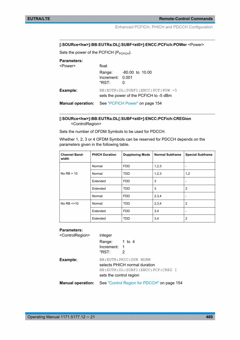
Remote-Control CommandsEUTRA/LTE
469Operating Manual 1171.5177.12 ─ 21
[:SOURce<hw>]:BB:EUTRa:DL[:SUBF<st0>]:ENCC:PCFich:POWer <Power>
Sets the power of the PCFICH (PPCFICH).
Parameters:<Power> float
Range: -80.00 to 10.00Increment: 0.001*RST: 0
Example: BB:EUTR:DL:SUBF1:ENCC:PCF:POW -5sets the power of the PCFICH to -5 dBm
Manual operation: See "PCFICH Power" on page 154
[:SOURce<hw>]:BB:EUTRa:DL[:SUBF<st0>]:ENCC:PCFich:CREGion<ControlRegion>
Sets the number of OFDM Symbols to be used for PDCCH.
Whether 1, 2, 3 or 4 OFDM Symbols can be reserved for PDCCH depends on theparameters given in the following table.
Channel Band-width
PHICH Duration Dupplexing Mode Normal Subframe Special Subframe
Normal FDD 1,2,3 -
No RB > 10 Normal TDD 1,2,3 1,2
Extended FDD 3 -
Extended TDD 3 2
Normal FDD 2,3,4 -
No RB <=10 Normal TDD 2,3,4 2
Extended FDD 3,4 -
Extended TDD 3,4 2
Parameters:<ControlRegion> integer
Range: 1 to 4Increment: 1*RST: 2
Example: BB:EUTR:PHIC:DUR NORMselects PHICH normal durationBB:EUTR:DL:SUBF1:ENCC:PCF:CREG 1sets the control region
Manual operation: See "Control Region for PDCCH" on page 154
Enhanced PCFICH, PHICH and PDCCH Configuration

Remote-Control CommandsEUTRA/LTE
470Operating Manual 1171.5177.12 ─ 21
[:SOURce<hw>]:BB:EUTRa:DL[:SUBF<st0>]:ENCC:PHICh:PMODe <PowerMode>
Determines whether all PHICH in a PHICH group are send with the same power orenables the adjustment of each PPHICH individualy.
Parameters:<PowerMode> CONSt | IND
CONStThe power of a PHICH (PPHICH) in a PHICH group is set withthe command SOUR:BB:EUTR:DL:ENCC:PHIC:POW.
INDThe power of the individual PHICHs is set with the command*RST: CONSt
Example: BB:EUTR:DL:SUBF1:ENCC:PHIC:PMOD CONSsets the power modeBB:EUTR:DL:SUBF1:ENCC:PHIC:POW -5sets the power of one PHICHs to -5 dB; all PHICHs in thePHICH group are send with this power.
Manual operation: See "Power Mode" on page 156
[:SOURce<hw>]:BB:EUTRa:DL[:SUBF<st0>]:ENCC:PHICh:POWer <Power>
Sets the power of one PHICH (PPHICH) in a PHICH group, i.e. the total power of onePHICH group is the sum of the power of the transmitted PHICHs whitin this group.
Parameters:<Power> float
Range: -80.00 dB to 10.00 dBIncrement: 0.001*RST: 0 dB
Example: SOUR:BB:EUTR:DL:SUBF2:ENCC:PHIC:PMOD CONSSOUR:BB:EUTR:DL:SUBF2:ENCC:PHIC:NOGR 1SOUR:BB:EUTR:DL:SUBF2:CYCP NORMSOUR:BB:EUTR:DL:SUBF2:ENCC:PHIC:ANP1 '1---1---'SOUR:BB:EUTR:DL:SUBF2:ENCC:PHIC:POW - 3sets the power of one PHICHs in a PHICH group to -3 dB
Manual operation: See "PHICH Power" on page 156
[:SOURce<hw>]:BB:EUTRa:DL[:SUBF<st0>]:ENCC:PHICh:GROup<ch0>:ITEM<user0>:POW <Power>
Sets the power of the individual PHICHs.
Enhanced PCFICH, PHICH and PDCCH Configuration
Remote-Control CommandsEUTRA/LTE
471Operating Manual 1171.5177.12 ─ 21
Parameters:<Power> float
Range: -80.00 dB to 10.00 dBIncrement: 0.001 dB*RST: 0 dB
Example: BB:EUTR:DL:SUBF1:ENCC:PHIC:PMOD INDsets the power modeBB:EUTR:DL:SUBF1:ENCC:PHIC:GRO1:ITEM4:POW -5sets the power of the PHICH#5 in the second PHICH group to -5dB
Manual operation: See "Power Settings Config." on page 156
[:SOURce<hw>]:BB:EUTRa:DL[:SUBF<st0>]:ENCC:PHICh:NOGRoups<GroupCount>
Sets the number of available PHICH groups.
Parameters:<GroupCount> integer
Range: 0 to 56Increment: 1*RST: 2
Example: BB:EUTR:DL:SUBF1:ENCC:PHIC:NOGR 4sets the number of PHICH groups
Manual operation: See "Number of PHICH Groups" on page 155
[:SOURce<hw>]:BB:EUTRa:DL[:SUBF<st0>]:ENCC:PHICh:ANPattern<ch0><AnPattern>
Sets the ACK/NACK pattern for the corresponding PHICH group.
A "1" indicates an ACK, a "0" - a NACK, a "-" indicates DTX.
Suffix: <ch0>
.0 .. 59
Parameters:<AnPattern> string
Example: BB:EUTR:DL:SUBF1:ENCC:PHIC:ANP2 '1010--11'sets the ACK/NACK pattern for PHICH Group number 2
Manual operation: See "ACK/NACK Pattern Group 0 .. 9" on page 156
[:SOURce<hw>]:BB:EUTRa:DL[:SUBF<st0>]:ENCC:PDCCh:POWer <Power>
Sets the power of the PDCCH (PPDCCH).
Enhanced PCFICH, PHICH and PDCCH Configuration
Remote-Control CommandsEUTRA/LTE
472Operating Manual 1171.5177.12 ─ 21
The value set with this parameter is also displayed in the allocation table for the corre-sponding allocation.
Parameters:<Power> float
Range: -80.00 to 10.00Increment: 0.001*RST: 0
Example: BB:EUTR:DL:SUBF1:ENCC:PDCC:POW -5sets the power of the PDCCH to -5dB
Manual operation: See "PDCCH Power" on page 157
[:SOURce<hw>]:BB:EUTRa:DL[:SUBF<st0>]:ENCC:PDCCh:BITS <PhysBits>
Defines the number of bits allocated for PDCCH.
Parameters:<PhysBits> integer
Range: 0 to 100000Increment: 1*RST: 0
Example: BB:EUTR:DL:SUBF1:ENCC:STAT ONenables PDCCH.BB:EUTR:DL:SUBF1:ENCC:PDCC:BITS?queries the number of bitsResponse: 3144
Manual operation: See "Number of Bits / REGs / CCEs (PDCCH)" on page 157
[:SOURce<hw>]:BB:EUTRa:DL[:SUBF<st0>]:ENCC:PDCCh:AVRegs<AvailRegionCoun>
Defines the number of the REGs that are available for the PDCCH allocation.
Parameters:<AvailRegionCoun> integer
Range: 0 to 100000Increment: 1*RST: 0
Example: BB:EUTR:DL:SUBF1:ENCC:STAT ONenables PDCCH.BB:EUTR:DL:SUBF1:ENCC:PDCC:AVR?queries the number of REGsResponse: 393
Manual operation: See "Number of available REGs (PDCCH)" on page 157
Enhanced PCFICH, PHICH and PDCCH Configuration
Remote-Control CommandsEUTRA/LTE
473Operating Manual 1171.5177.12 ─ 21
[:SOURce<hw>]:BB:EUTRa:DL[:SUBF<st0>]:ENCC:PDCCh:AVCCes<AvailCceCount>
Queries the number of the control channel elements (CCEs) that are available for thePDCCH allocation.
Parameters:<AvailCceCount> integer
Range: 0 to 100000Increment: 1*RST: 0
Example: BB:EUTR:DL:SUBF1:ENCC:STAT ONenables PDCCH.BB:EUTR:DL:SUBF1:ENCC:PDCC:AVCC?queries the number of CCEsResponse 43
Manual operation: See "Number of available CCEs (PDCCH)" on page 158
[:SOURce<hw>]:BB:EUTRa:DL[:SUBF<st0>]:ENCC:PDCCh:FORMat <Format>
Sets the PDCCH format.
The PDCCH format determines how many CCEs (control channel elements) will beused for the transmission of the PDCCH.
Enhanced PCFICH, PHICH and PDCCH Configuration
Remote-Control CommandsEUTRA/LTE
474Operating Manual 1171.5177.12 ─ 21
Parameters:<Format> VAR | -1 | 0 | 1 | 2 | 3
VAREnables full flexibility by the configuration of the downlink controlinformation (DCI) format and content.-1Proprietary format for legacy support.Disables precoding.This format corresponds to the transmission of one PDCCH onall available REGs, i.e.# REGs availablePDCCH = #REGs allocatedPDCCH,#PDCCH=1,#DummyREGs=0.This format has to be used while performing signal analysis withR&S FSQ.0One PDCCH is transmitted on one CCE, i.e. 9 REGs.1One PDCCH is transmitted on two CCEs, i.e. 18 REGs.2One PDCCH is transmitted on four CCEs, i.e. 36 REGs.3One PDCCH is transmitted on eight CCEs, i.e. 72 REGs.*RST: VAR
Example: BB:EUTR:DL:SUBF2:ENCC:PDCC:FORM 0sets the PDCCH format.
Manual operation: See "PDCCH Format" on page 158
[:SOURce<hw>]:BB:EUTRa:DL[:SUBF<st0>]:ENCC:PDCCh:NOPDcchs<PdcchCount>
Sets the number of PDCCHs to be transmitted.
The maximum number PDCCH that can be transmitted on the available REGs forPDCCH deppends on the number of REGs (#REG) reserved for the transmission ofone PDCCH, i.e. depends on the selected PDCCH format and is calculated as follow:
#PDCCH = # REGs availablePDCCH / #REG.
Parameters:<PdcchCount> integer
Range: 0 to maxIncrement: 1*RST: 0
Enhanced PCFICH, PHICH and PDCCH Configuration
Remote-Control CommandsEUTRA/LTE
475Operating Manual 1171.5177.12 ─ 21
Example: BB:EUTR:DL:SUBF2:ENCC:PDCC:FORM 0sets the PDCCH format.BB:EUTR:DL:SUBF2:ENCC:PDCC:NOPD 20sets the number of PDCCHs.
Manual operation: See "Number of PDCCHs" on page 159
[:SOURce<hw>]:BB:EUTRa:DL[:SUBF<st0>]:ENCC:PDCCh:ALRegs<AllocRegionCoun>
Defines the number of REGs that are actually allocated for PDCCH transmission(#REGs allocatedPDCCH).
Parameters:<AllocRegionCoun> integer
Range: 0 to 100000Increment: 1*RST: 0
Example: BB:EUTR:DL:SUBF2:ENCC:PDCC:FORM 0sets the PDCCH format.BB:EUTR:DL:SUBF2:ENCC:PDCC:NOPD 20sets the number of PDCCHs.BB:EUTR:DL:SUBF2:ENCC:PDCC:ALR?queries the number of REGsResponse: 180
Manual operation: See "Number of REGs allocated to PDCCH" on page 159
[:SOURce<hw>]:BB:EUTRa:DL[:SUBF<st0>]:ENCC:PDCCh:DREGs<DummyRegsCount>
Defines the the number of REGs that are available for the PDCCH allocation but arenot allocated.
Parameters:<DummyRegsCount> integer
Range: 0 to 100000Increment: 1*RST: 0
Example: BB:EUTR:DL:SUBF2:ENCC:PDCC:FORM 0sets the PDCCH format.BB:EUTR:DL:SUBF2:ENCC:PDCC:NOPD 20sets the number of PDCCHs.BB:EUTR:DL:SUBF2:ENCC:PDCC:ALR?queries the number of REGsResponse: 180BB:EUTR:DL:SUBF2:ENCC:PDCC:DREG?queries the number of dummy REGsResponse: 213
Enhanced PCFICH, PHICH and PDCCH Configuration
Remote-Control CommandsEUTRA/LTE
476Operating Manual 1171.5177.12 ─ 21
Manual operation: See "Number of Dummy REGs" on page 159
[:SOURce<hw>]:BB:EUTRa:DL[:SUBF<st0>]:ENCC:PDCCh:DATA <Data>
Selects the data source for PDCCH.
Parameters:<Data> PN9 | PN11 | PN15 | PN16 | PN20 | PN21 | PN23 | PATTern |
DLISt | ZERO | ONE*RST: PN9
Example: BB:EUTR:DL:SUBF2:ENCC:PDCC:FORM 0sets the PDCCH format.BB:EUTR:DL:SUBF1:ENCC:PDCC:DATA PN9PN9 is selected as data source
Manual operation: See "Data Source" on page 160
[:SOURce<hw>]:BB:EUTRa:DL[:SUBF<st0>]:ENCC:PDCCh:PATTern <Pattern>
Selects the bit pattern for the PATT selection.
Parameters:<Pattern> <bit pattern>
*RST: #H0,1
Example: BB:EUTR:DL:SUBF2:ENCC:PDCC:FORM 0sets the PDCCH format.BB:EUTR:DL:SUBF1:ENCC:PDCC:DATA PATTPattern is selected as data sourceBB:EUTR:DL:SUBF1:ENCC:PDCC:PATT #H3F,8defines the bit pattern.
Manual operation: See "Data Source" on page 160
[:SOURce<hw>]:BB:EUTRa:DL[:SUBF<st0>]:ENCC:PDCCh:DSELect <Filename>
Selects the data list for the DLISt data source selection.
The lists are stored in a directory of the user's choice. The directory applicable to thefollowing commands is defined with the command MMEMory:CDIR. To access the filesin this directory, you only have to give the file name, without the path and the file exten-sion.
Parameters:<Filename> string
Enhanced PCFICH, PHICH and PDCCH Configuration
Remote-Control CommandsEUTRA/LTE
477Operating Manual 1171.5177.12 ─ 21
Example: BB:EUTR:DL:SUBF2:ENCC:PDCC:FORM 0sets the PDCCH format.BB:EUTR:DL:SUBF1:ENCC:PDCC:DATA DLISselects the Data Lists data source.MMEM:CDIR '<root>Lists'selects the directory for the data lists.BB:EUTR:DL:SUBF1:ENCC:PDCC:DSEL 'eutra_pdcch'selects file eutra_pdcch as the data source. This file must bein the directory <root>Lists
[:SOURce<hw>]:BB:EUTRa:DL[:SUBF<st0>]:ENCC:PDCCh:DCRegs:TRSource<TranSource>
Sets the behavior of the dummy REGs, i.e. determines whether dummy data or DTX istransmitted.
Parameters:<TranSource> DATA | DTX
*RST: DATA
Example: BB:EUTR:DL:SUBF1:ENCC:PDCC:FORM VARsets the PDCCH format.BB:EUTR:DL:SUBF1:ENCC:PDCC:DCR:TRS DATADATA wil be transmitted
Manual operation: See "Dummy CCE REGs" on page 161
[:SOURce<hw>]:BB:EUTRa:DL[:SUBF<st0>]:ENCC:PDCCh:DCRegs:DATA<Data>
Selects the data source for PDCCH.
Parameters:<Data> PN9 | PN11 | PN15 | PN16 | PN20 | PN21 | PN23 | PATTern |
DLISt | ZERO | ONE*RST: PN9
Example: BB:EUTR:DL:SUBF1:ENCC:PDCC:FORM VARsets the PDCCH format.BB:EUTR:DL:SUBF1:ENCC:PDCC:DCR:DATA PN9PN9 is selected as data source
Manual operation: See "Dummy CCE Data Source" on page 161
[:SOURce<hw>]:BB:EUTRa:DL[:SUBF<st0>]:ENCC:PDCCh:DCRegs:DSELect<Filename>
Selects the data list for the DLISt data source selection.
Enhanced PCFICH, PHICH and PDCCH Configuration
Remote-Control CommandsEUTRA/LTE
478Operating Manual 1171.5177.12 ─ 21
The lists are stored in a directory of the user's choice. The directory applicable to thefollowing commands is defined with the command MMEMory:CDIR. To access the filesin this directory, you only have to give the file name, without the path and the file exten-sion.
Parameters:<Filename> string
Example: BB:EUTR:DL:SUBF1:ENCC:PDCC:FORM VARsets the PDCCH format.BB:EUTR:DL:SUBF1:ENCC:PDCC:DCR:DATA DLISselects the Data Lists data source.MMEM:CDIR '<root>Lists'selects the directory for the data lists.BB:EUTR:DL:SUBF1:ENCC:PDCC:DCR:DSEL'eutra_pdcch'selects file eutra_pdcch as the data source. This file must bein the directory <root>Lists
Manual operation: See "Dummy CCE Data Source" on page 161
[:SOURce<hw>]:BB:EUTRa:DL[:SUBF<st0>]:ENCC:PDCCh:DCRegs:PATTern<Pattern>
Selects the bit pattern for the PATT selection.
Parameters:<Pattern> <bit pattern>
*RST: #H0,1
Example: BB:EUTR:DL:SUBF1:ENCC:PDCC:FORM VARsets the PDCCH format.BB:EUTR:DL:SUBF1:ENCC:PDCC:DCR:DATA PATTPattern is selected as data sourceBB:EUTR:DL:SUBF1:ENCC:PDCC:DCR:PATT #H3F,8defines the bit pattern.
Manual operation: See "Dummy CCE Data Source" on page 161
[:SOURce<hw>]:BB:EUTRa:DL[:SUBF<st0>]:ENCC:PDCCh:EXTC:SITem<SelectedItem>
Selects an PDCCH item, i.e. a row in the DCI table.
Parameters:<SelectedItem> integer
Range: 0 to 19Increment: 1*RST: 0
Enhanced PCFICH, PHICH and PDCCH Configuration
Remote-Control CommandsEUTRA/LTE
479Operating Manual 1171.5177.12 ─ 21
Example: BB:EUTR:DL:SUBF1:ENCC:PDCC:FORM VARsets the PDCCH format.BB:EUTR:DL:SUBF1:ENCC:PDCC:EXTC:SIT 2selects the third row in the DCI table
Manual operation: See "Standard configuration functions" on page 161
[:SOURce<hw>]:BB:EUTRa:DL[:SUBF<st0>]:ENCC:PDCCh:EXTC:APPend
Adds a new row at the end of the DCI table.
Example: BB:EUTR:DL:SUBF1:ENCC:PDCC:FORM VARsets the PDCCH format.BB:EUTR:DL:SUBF1:ENCC:PDCC:EXTC:APPadds a new row
Manual operation: See "Standard configuration functions" on page 161
[:SOURce<hw>]:BB:EUTRa:DL[:SUBF<st0>]:ENCC:PDCCh:EXTC:INSert
Insert a new row before the currently selected item.
Example: BB:EUTR:DL:SUBF1:ENCC:PDCC:FORM VARsets the PDCCH format.BB:EUTR:DL:SUBF1:ENCC:PDCC:EXTC:SIT 2selects the third row in the DCI tableBB:EUTR:DL:SUBF1:ENCC:PDCC:EXTC:INSinserts a new row before the third one
Manual operation: See "Standard configuration functions" on page 161
[:SOURce<hw>]:BB:EUTRa:DL[:SUBF<st0>]:ENCC:PDCCh:EXTC:DELete
Deletes the selected row.
Example: BB:EUTR:DL:SUBF1:ENCC:PDCC:FORM VARsets the PDCCH format.BB:EUTR:DL:SUBF1:ENCC:PDCC:EXTC:SIT 2selects the third row in the DCI tableBB:EUTR:DL:SUBF1:ENCC:PDCC:EXTC:DELdelets the third row
Usage: Event
Manual operation: See "Standard configuration functions" on page 161
[:SOURce<hw>]:BB:EUTRa:DL[:SUBF<st0>]:ENCC:PDCCh:EXTC:DOWN[:SOURce<hw>]:BB:EUTRa:DL[:SUBF<st0>]:ENCC:PDCCh:EXTC:UPMoves the selected row down or up.
Enhanced PCFICH, PHICH and PDCCH Configuration
Remote-Control CommandsEUTRA/LTE
480Operating Manual 1171.5177.12 ─ 21
Example: BB:EUTR:DL:SUBF1:ENCC:PDCC:FORM VARsets the PDCCH format.BB:EUTR:DL:SUBF1:ENCC:PDCC:EXTC:SIT 2selects the third row in the DCI tableBB:EUTR:DL:SUBF1:ENCC:PDCC:EXTC:UPmoves the third row one row up
Manual operation: See "Standard configuration functions" on page 161
[:SOURce<hw>]:BB:EUTRa:DL[:SUBF<st0>]:ENCC:PDCCh:EXTC:CONFlicts?
Queries the number of conflicts between the DCI format.
To querry whether there is a conflict in one particular PDCCH item, use the command[:SOURce<hw>]: BB: EUTRa:DL[: SUBF<st0>]: ENCC: PDCCh: EXTC:ITEM<ch0>: CONFlict? on page 484.
Return values: <NoOfConf> integer
Range: 0 to 20Increment: 1*RST: 0
Example: SOURce1:BB:EUTRa:DL:SUBF1:ENCC:PDCCh:FORMatVARiableSOURce1:BB:EUTRa:DL:SUBF1:ENCC:PDCCh:EXTC:CONFlicts?Response: 1SOURce1:BB:EUTRa:DL:SUBF1:ENCC:PDCCh:EXTC:UITems?Response: 2SOURce1:BB:EUTRa:DL:SUBF1:ENCC:PDCCh:EXTC:ITEM0:CONFlict?Response: 0SOURce1:BB:EUTRa:DL:SUBF1:ENCC:PDCCh:EXTC:ITEM1:CONFlict?Response: 1The DCI conflict is in the second PDCCH itemSOURce1:BB:EUTRa:DL:SUBF1:ENCC:PDCCh:EXTC:SOLVe
Usage: Query only
Manual operation: See "Resolve Conflicts" on page 162
[:SOURce<hw>]:BB:EUTRa:DL[:SUBF<st0>]:ENCC:PDCCh:EXTC:SOLVe?
Triggers a built-in algorithm that re-assigns automatically the CCE values dependingon the configured "Search Space"; previously configured CCE values will not be main-tained.
If the conflict can not be resolved automatically, the values are left unchanged.
Enhanced PCFICH, PHICH and PDCCH Configuration

Remote-Control CommandsEUTRA/LTE
481Operating Manual 1171.5177.12 ─ 21
Example: :SOURce:BB:EUTRa:DL:SUBF1:ENCC:PDCCh:EXTC:SOLVeUsage: Query only
Manual operation: See "Resolve Conflicts" on page 162
[:SOURce<hw>]:BB:EUTRa:DL[:SUBF<st0>]:ENCC:PDCCh:EXTC:RESet
Resets the table.
Example: BB:EUTR:DL:SUBF1:ENCC:PDCC:FORM VARsets the PDCCH format.BB:EUTR:DL:SUBF1:ENCC:PDCC:EXTC:RESresets the table
Manual operation: See "Reset" on page 162
[:SOURce<hw>]:BB:EUTRa:DL[:SUBF<st0>]:ENCC:PDCCh:EXTC:UITems?
Queries the number of used PDCCH items.
Parameters:<UsedItems> integer
Range: 1 to 20Increment: 1*RST: 1
Example: SOURce1:BB:EUTRa:DL:SUBF1:ENCC:PDCCh:FORMatVARiableSOURce1:BB:EUTRa:DL:SUBF1:ENCC:PDCCh:EXTC:APPendSOURce1:BB:EUTRa:DL:SUBF1:ENCC:PDCCh:EXTC:UITems?Response: 2
Usage: Query only
Manual operation: See "Number of Used PDCCH Items" on page 162
[:SOURce<hw>]:BB:EUTRa:DL[:SUBF<st0>]:ENCC:PDCCh:EXTC:ITEM<ch0>:DCIFmt <DciFormat>
Sets the DCI format for the selected PDCCH.
Parameters:<DciFormat> F0 | F1 | F1A | F1B | F1C | F1D | F2 | F2A | F3 | F3A | F2B | F2C
*RST: F0
Enhanced PCFICH, PHICH and PDCCH Configuration
Remote-Control CommandsEUTRA/LTE
482Operating Manual 1171.5177.12 ─ 21
Example: SOURce1:BB:EUTRa:DL:SUBF1:ENCC:PDCCh:FORMatVARiablesets the PDCCH format.SOURce1:BB:EUTRa:DL:SUBF1:ENCC:PDCCh:EXTC:ITEM1:DCIFmt F1sets the DCI format
Manual operation: See "DCI Format" on page 163
[:SOURce<hw>]:BB:EUTRa:DL[:SUBF<st0>]:ENCC:PDCCh:EXTC:ITEM<ch0>:UEID <Ueid>
Sets the n_RNTI for the selected PDCCH.
Parameters:<Ueid> integer
Range: 0 to 65535Increment: 1*RST: 0
Example: BB:EUTR:DL:SUBF1:ENCC:PDCC:FORM VARsets the PDCCH format.BB:EUTR:DL:SUBF1:ENCC:PDCC:EXTC:ITEM1:UEID 100sets the n_RNTI
Manual operation: See "UE_ID/n_RNTI" on page 163
[:SOURce<hw>]:BB:EUTRa:DL[:SUBF<st0>]:ENCC:PDCCh:EXTC:ITEM<ch0>:CELL <CellIdx>
Determines the component carrier the corresponding DCI is transmitted on.
Parameters:<CellIdx> integer
Range: 0 to 7Increment: 1*RST: 0
Options: R&S SMx/AMU-K85
Manual operation: See "Cell Index" on page 163
[:SOURce<hw>]:BB:EUTRa:DL[:SUBF<st0>]:ENCC:PDCCh:EXTC:ITEM<ch0>:PFMT <Format>
Sets the PDCCH format for the selected PDCCH.
Parameters:<Format> integer
Range: 0 to 3Increment: 1*RST: 0
Enhanced PCFICH, PHICH and PDCCH Configuration
Remote-Control CommandsEUTRA/LTE
483Operating Manual 1171.5177.12 ─ 21
Example: BB:EUTR:DL:SUBF1:ENCC:PDCC:FORM VARsets PDCCH format variable.BB:EUTR:DL:SUBF1:ENCC:PDCC:EXTC:ITEM1:PFMT 0sets the PDCCH format.
Manual operation: See "PDCCH Format (Variable)" on page 165
[:SOURce<hw>]:BB:EUTRa:DL[:SUBF<st0>]:ENCC:PDCCh:EXTC:ITEM<ch0>:NCCes <CceCount>
Defines the number of control channel elements used for the transmission of thePDCCH.
Parameters:<CceCount> integer
Range: 0 to 100000Increment: 1*RST: 0
Example: BB:EUTR:DL:SUBF1:ENCC:PDCC:FORM VARsets the PDCCH format.BB:EUTR:DL:SUBF1:ENCC:PDCC:EXTC:ITEM1:NCC?queries the number of CCEs
Manual operation: See "Number CCEs" on page 165
[:SOURce<hw>]:BB:EUTRa:DL[:SUBF<st0>]:ENCC:PDCCh:EXTC:ITEM<ch0>:CINDex <CceIndex>
Sets the CCE start index.
Parameters:<CceIndex> integer
Range: 0 to 100000Increment: 1*RST: 0
Example: SOURce1:BB:EUTRa:DL:SUBF1:ENCC:PDCCh:FORMat VARsets the PDCCH format.SOURce1:BB:EUTRa:DL:SUBF1:ENCC:PDCCh:EXTC:ITEM1:CINDex 10sets the CCE start index
Manual operation: See "CCE Index" on page 166
[:SOURce<hw>]:BB:EUTRa:DL[:SUBF<st0>]:ENCC:PDCCh:EXTC:ITEM<ch0>:NDCCes <DummyCceCount>
Defines the number of dummy CCEs that are appended to the PDCCH.
Enhanced PCFICH, PHICH and PDCCH Configuration
Remote-Control CommandsEUTRA/LTE
484Operating Manual 1171.5177.12 ─ 21
Parameters:<DummyCceCount> integer
Range: 0 to 100000Increment: 1*RST: 0
Example: BB:EUTR:DL:SUBF1:ENCC:PDCC:FORM VARsets the PDCCH format.BB:EUTR:DL:SUBF1:ENCC:PDCC:EXTC:ITEM1:NDCC?queries the number of dummy CCEs
Manual operation: See "Number of Dummy CCEs" on page 166
[:SOURce<hw>]:BB:EUTRa:DL[:SUBF<st0>]:ENCC:PDCCh:EXTC:ITEM<ch0>:CONFlict?
Indicates a conflict between two DCI formats.
Return values: <Conflict> 0 | 1 | OFF | ON
*RST: OFF
Example: SOURce1:BB:EUTRa:DL:SUBF1:ENCC:PDCCh:EXTC:ITEM1:CONFlict?queries whether there is a conflict or not.
Usage: Query only
Manual operation: See "Conflict (DCI)" on page 166
[:SOURce<hw>]:BB:EUTRa:DL[:SUBF<st0>]:ENCC:PDCCh:EXTC:ITEM<ch0>:USER <User>
Selects the User the DCI is dedicated to.
The available "DCI Formats" depend on the value of this parameter.
Parameters:<User> USER1 | USER2 | USER3 | USER4 | PRNTi | SIRNti | RARNti |
NONE*RST: USER1
Return values: <User> USER1 | USER2 | USER3 | USER4 | PRNTi | SIRNti | RARNti |
NONE | U1SPs | U2SPs | U3SPs | U4SPs*RST: USER1
Example: SOURce1:BB:EUTRa:DL:SUBF1:ENCC:PDCCh:EXTC:ITEM1:USER USER2the DCI is dedicated to User 2
Manual operation: See "User" on page 162
Enhanced PCFICH, PHICH and PDCCH Configuration
Remote-Control CommandsEUTRA/LTE
485Operating Manual 1171.5177.12 ─ 21
[:SOURce<hw>]:BB:EUTRa:DL[:SUBF<st0>]:ENCC:PDCCh:EXTC:ITEM<ch0>:SESPace <SearchSpace>
If enabled, this parameter configures the PDCCH DCI to be transmitted within the com-mon or UE-specific search space.
Note: The 3GPP specification defines two kinds of search spaces, the common andthe UE-specific (UE) search space. Avoid the use of the AUTO and OFF values; this val-ues are provided for backwards compatibility reasons only.
Parameters:<SearchSpace> OFF | AUTO | COMMon | UE | ON | 0 | 1
*RST: OFF
Example: BB:EUTR:DL:SUBF1:ENCC:PDCC:EXTC:ITEM1:SESP UEthe DCI is transmitted within the UE-specific search space.
Manual operation: See "Search Space" on page 164
[:SOURce<hw>]:BB:EUTRa:DL[:SUBF<st0>]:ENCC:PDCCh:EXTC:ITEM<ch0>:DCIConf:APLayer <ApLayerId>
Sets the DCI Format 2C field antenna port(s), layer, scrambling Id.
Parameters:<ApLayerId> integer
Range: 0 to 7*RST: 0
Example: SOURce1:BB:EUTRa:DL:USER1:TXM M9SOURce1:BB:EUTRa:DL:SUBF1:ENCC:PDCCh:FORMatVARiableSOURce1:BB:EUTRa:DL:SUBF1:ENCC:PDCCh:EXTC:ITEM1:DCIFmt F2CSOURce1:BB:EUTRa:DL:SUBF1:ENCC:PDCCh:EXTC:ITEM1:DCIConf:APLayer 2
Manual operation: See "DCI Format 2/2A/2B/2C" on page 174
[:SOURce<hw>]:BB:EUTRa:DL[:SUBF<st0>]:ENCC:PDCCh:EXTC:ITEM<ch0>:DCIConf:BITData?
Queries the resulting bit data as selected with the DCI format parameters.
Return values: <BitData> string
Example: BB:EUTR:DL:SUBF1:ENCC:PDCC:FORM VARsets the PDCCH format.BB:EUTR:DL:SUBF1:ENCC:PDCC:EXTC:ITEM1:DCIC:BITD?queries the bit data
Enhanced PCFICH, PHICH and PDCCH Configuration
Remote-Control CommandsEUTRA/LTE
486Operating Manual 1171.5177.12 ─ 21
Usage: Query only
Manual operation: See "Bit Data" on page 167
[:SOURce<hw>]:BB:EUTRa:DL[:SUBF<st0>]:ENCC:PDCCh:EXTC:ITEM<ch0>:DCIConf:CIField <CaIndField>
The CIF is present in each DCI Format and indentifies the component carrier that car-ries the PDSCH or PUSCH for the particuliar PDCCH in the cross-carrier approach(see figure 3-26).
Parameters:<CaIndField> integer
Range: 0 to 7Increment: 1*RST: 0
Example: BB:EUTR:DL:CA:STAT ONBB:EUTR:DL:USER2:CA:STAT ONBB:EUTR:DL:CA:CELL0:CIF ONBB:EUTR:DL:ENCC:PDCC:EXTC:ITEM1:DCIC:CIF 1
Options: R&S SMx/AMU-K85
Manual operation: See "Carrier Indicator Field (CIF)" on page 166
[:SOURce<hw>]:BB:EUTRa:DL[:SUBF<st0>]:ENCC:PDCCh:EXTC:ITEM<ch0>:DCIConf:F1AMode <Format1aMode>
Selects the mode of the DCI format.
Parameters:<Format1aMode> PDSCh | PRACh
*RST: PDSCh
Example: BB:EUTR:DL:SUBF1:ENCC:PDCC:FORM VARsets the PDCCH format.BB:EUTR:DL:SUBF1:ENCC:PDCC:EXTC:ITEM1:DCIF F1Asets the DCI formatBB:EUTR:DL:SUBF1:ENCC:PDCC:EXTC:ITEM1:DCIC:F1AMPRACsets the mode
Manual operation: See "DCI Format 1A" on page 169
[:SOURce<hw>]:BB:EUTRa:DL[:SUBF<st0>]:ENCC:PDCCh:EXTC:ITEM<ch0>:DCIConf:PRACh:PRINdex <PreambleIndex>
(PRACH mode only)
Sets the DCI Format 1A field Preamble index.
Enhanced PCFICH, PHICH and PDCCH Configuration
Remote-Control CommandsEUTRA/LTE
487Operating Manual 1171.5177.12 ─ 21
Parameters:<PreambleIndex> integer
Range: 0 to 63Increment: 1*RST: 0
Example: BB:EUTR:DL:SUBF1:ENCC:PDCC:FORM VARsets the PDCCH format.BB:EUTR:DL:SUBF1:ENCC:PDCC:EXTC:ITEM1:DCIF F1Asets the DCI formatBB:EUTR:DL:SUBF1:ENCC:PDCC:EXTC:ITEM1:F1AM PRACsets the modeBB:EUTR:DL:SUBF1:ENCC:PDCC:EXTC:ITEM1:DCIC:PRAC:PRIN 10sets the preamble indexe
Manual operation: See "DCI Format 1A" on page 169
[:SOURce<hw>]:BB:EUTRa:DL[:SUBF<st0>]:ENCC:PDCCh:EXTC:ITEM<ch0>:DCIConf:PRACh:MINDex <MaskIndex>
(PRACH mode only)
Sets the DCI Format 1A field PRACH Mask Index.
Parameters:<MaskIndex> integer
Range: 0 to 15Increment: 1*RST: 0
Example: BB:EUTR:DL:SUBF1:ENCC:PDCC:FORM VARsets the PDCCH format.BB:EUTR:DL:SUBF1:ENCC:PDCC:EXTC:ITEM1:DCIF F1Asets the DCI formatBB:EUTR:DL:SUBF1:ENCC:PDCC:EXTC:ITEM1:F1AM PRACsets the modeBB:EUTR:DL:SUBF1:ENCC:PDCC:EXTC:ITEM1:DCIC:PRAC:MIND 10sets the preamble indexe
Manual operation: See "DCI Format 1A" on page 169
[:SOURce<hw>]:BB:EUTRa:DL[:SUBF<st0>]:ENCC:PDCCh:EXTC:ITEM<ch0>:DCIConf:CSIRequest <CsiRequest>
Sets the DCI Format 0 field CSI/CQI Request.
Enhanced PCFICH, PHICH and PDCCH Configuration
Remote-Control CommandsEUTRA/LTE
488Operating Manual 1171.5177.12 ─ 21
Parameters:<CsiRequest> integer
Range: 0 to 3Increment: 1*RST: 0
Example: BB:EUTR:DL:SUBF1:ENCC:PDCC:FORM VARBB:EUTR:DL:SUBF1:ENCC:PDCC:EXTC:ITEM1:DCIF F0BB:EUTR:DL:SUBF1:ENCC:PDCC:EXTC:ITEM1:DCIC:CSIR1
Manual operation: See "DCI Format 0" on page 167
[:SOURce<hw>]:BB:EUTRa:DL[:SUBF<st0>]:ENCC:PDCCh:EXTC:ITEM<ch0>:DCIConf:CSDMrs <CyclicShftDmRs>
Sets the DCI Format 0 field cyclic shift for DMRS.
Parameters:<CyclicShftDmRs> integer
Range: 0 to 7Increment: 1*RST: 0
Example: BB:EUTR:DL:SUBF1:ENCC:PDCC:FORM VARsets the PDCCH format.BB:EUTR:DL:SUBF1:ENCC:PDCC:EXTC:ITEM1:DCIF F0sets the DCI formatBB:EUTR:DL:SUBF1:ENCC:PDCC:EXTC:ITEM1:DCIC:CSDM1sets the cyclic shift
Manual operation: See "DCI Format 0" on page 167
[:SOURce<hw>]:BB:EUTRa:DL[:SUBF<st0>]:ENCC:PDCCh:EXTC:ITEM<ch0>:DCIConf:DLAindex <DlAssignIndex>
(Enabled for TDD mode only)
Sets the DCI Format 0/1A/1B/1D/2/2A field downlink assignment index.
Parameters:<DlAssignIndex> integer
Range: 0 to 3Increment: 1*RST: 0
Enhanced PCFICH, PHICH and PDCCH Configuration
Remote-Control CommandsEUTRA/LTE
489Operating Manual 1171.5177.12 ─ 21
Example: BB:EUTR:DUPL TDDselects TDD mode.BB:EUTR:DL:SUBF1:ENCC:PDCC:FORM VARsets the PDCCH format.BB:EUTR:DL:SUBF1:ENCC:PDCC:EXTC:ITEM1:DCIF F0sets the DCI formatBB:EUTR:DL:SUBF1:ENCC:PDCC:EXTC:ITEM1:DCIC:DLA1sets the downlink assignment index
Manual operation: See "DCI Format 0" on page 167
[:SOURce<hw>]:BB:EUTRa:DL[:SUBF<st0>]:ENCC:PDCCh:EXTC:ITEM<ch0>:DCIConf:DPOFfset <DpOffset>
Sets the DCI Format 1D field downlink power offset.
Parameters:<DpOffset> 0 | 1 | OFF | ON
*RST: OFF
Example: BB:EUTR:DL:SUBF1:ENCC:PDCC:FORM VARsets the PDCCH format.BB:EUTR:DL:SUBF1:ENCC:PDCC:EXTC:ITEM1:DCIF F1Dsets the DCI formatBB:EUTR:DL:SUBF1:ENCC:PDCC:EXTC:ITEM1:DCIC:DPOFONenables downlink power offset
Manual operation: See "DCI Format 1D" on page 173
[:SOURce<hw>]:BB:EUTRa:DL[:SUBF<st0>]:ENCC:PDCCh:EXTC:ITEM<ch0>:DCIConf:GAP <Gap>
Sets the DCI Format 1A/1B/1C/1D field GAP value.
Parameters:<Gap> ON | OFF
*RST: OFF
Example: BB:EUTR:DL:SUBF1:ENCC:PDCC:FORM VARsets the PDCCH format.BB:EUTR:DL:SUBF1:ENCC:PDCC:EXTC:ITEM1:DCIF F1Csets the DCI formatBB:EUTR:DL:SUBF1:ENCC:PDCC:EXTC:ITEM1:DCIC:GAPONenables gap value
Manual operation: See "DCI Format 1A" on page 169
Enhanced PCFICH, PHICH and PDCCH Configuration
Remote-Control CommandsEUTRA/LTE
490Operating Manual 1171.5177.12 ─ 21
[:SOURce<hw>]:BB:EUTRa:DL[:SUBF<st0>]:ENCC:PDCCh:EXTC:ITEM<ch0>:DCIConf:HPN <HarqProcessNumb>
Sets the DCI Format 1/1A/1B/1D/2/2A field HARQ porcess number.
Parameters:<HarqProcessNumb> integer
Range: 0 to 15Increment: 1*RST: 0
Example: BB:EUTR:DL:SUBF1:ENCC:PDCC:FORM VARsets the PDCCH format.BB:EUTR:DL:SUBF1:ENCC:PDCC:EXTC:ITEM1:DCIF F1Bsets the DCI formatBB:EUTR:DL:SUBF1:ENCC:PDCC:EXTC:ITEM1:DCIC:HPN5sets the HARQ process number
Manual operation: See "DCI Format 1" on page 168
[:SOURce<hw>]:BB:EUTRa:DL[:SUBF<st0>]:ENCC:PDCCh:EXTC:ITEM<ch0>:DCIConf:MCSR <Mcsr>
Sets the DCI Format 0/1/1A/1B/1C/1D field Modulation and Coding Scheme.
Parameters:<Mcsr> integer
Range: 0 to 31Increment: 1*RST: 0
Example: BB:EUTR:DL:SUBF1:ENCC:PDCC:FORM VARBB:EUTR:DL:SUBF1:ENCC:PDCC:EXTC:ITEM1:DCIF F1BBB:EUTR:DL:SUBF1:ENCC:PDCC:EXTC:ITEM1:DCIC:MCSR5
Manual operation: See "DCI Format 0" on page 167
[:SOURce<hw>]:BB:EUTRa:DL[:SUBF<st0>]:ENCC:PDCCh:EXTC:ITEM<ch0>:DCIConf:NDI <NewDataIndicat>
Sets the DCI Format 0/1/1A/1B/1D field New Data Indicator.
Parameters:<NewDataIndicat> ON | OFF
*RST: OFF
Enhanced PCFICH, PHICH and PDCCH Configuration
Remote-Control CommandsEUTRA/LTE
491Operating Manual 1171.5177.12 ─ 21
Example: BB:EUTR:DL:SUBF1:ENCC:PDCC:FORM VARsets the PDCCH format.BB:EUTR:DL:SUBF1:ENCC:PDCC:EXTC:ITEM1:DCIF F1Bsets the DCI formatBB:EUTR:DL:SUBF1:ENCC:PDCC:EXTC:ITEM1:DCIC:NDIONsets the New Data Indicator
Manual operation: See "DCI Format 0" on page 167
[:SOURce<hw>]:BB:EUTRa:DL[:SUBF<st0>]:ENCC:PDCCh:EXTC:ITEM<ch0>:DCIConf:PFHopping <FreqHopState>
Sets the DCI Format 0 field PUSCH Frequency Hopping.
Parameters:<FreqHopState> 0 | 1 | OFF | ON
*RST: OFF
Example: BB:EUTR:DL:SUBF1:ENCC:PDCC:FORM VARsets the PDCCH format.BB:EUTR:DL:SUBF1:ENCC:PDCC:EXTC:ITEM1:DCIF F0sets the DCI formatBB:EUTR:DL:SUBF1:ENCC:PDCC:EXTC:ITEM1:DCIC:PFHONenables PUSCH Frequency Hopping
Manual operation: See "DCI Format 0" on page 167
[:SOURce<hw>]:BB:EUTRa:DL[:SUBF<st0>]:ENCC:PDCCh:EXTC:ITEM<ch0>:DCIConf:PMI <PmiState>
Sets the DCI Format 1B field PMI Confirmation for Precoding.
Parameters:<PmiState> ON | OFF
*RST: OFF
Example: BB:EUTR:DL:SUBF1:ENCC:PDCC:FORM VARsets the PDCCH format.BB:EUTR:DL:SUBF1:ENCC:PDCC:EXTC:ITEM1:DCIF F1Bsets the DCI formatBB:EUTR:DL:SUBF1:ENCC:PDCC:EXTC:ITEM1:DCIC:PMIONenebles PMI Confirmation for Precoding
Manual operation: See "DCI Format 1B" on page 171
Enhanced PCFICH, PHICH and PDCCH Configuration
Remote-Control CommandsEUTRA/LTE
492Operating Manual 1171.5177.12 ─ 21
[:SOURce<hw>]:BB:EUTRa:DL[:SUBF<st0>]:ENCC:PDCCh:EXTC:ITEM<ch0>:DCIConf:PRECinfo <PrecodingInfo>
Sets the DCI Format 2/2A field Precoding Information.
Parameters:<PrecodingInfo> integer
Range: 0 to 63Increment: 1*RST: 0
Example: BB:EUTR:DL:SUBF1:ENCC:PDCC:FORM VARsets the PDCCH format.BB:EUTR:DL:SUBF1:ENCC:PDCC:EXTC:ITEM1:DCIF F2sets the DCI formatBB:EUTR:DL:SUBF1:ENCC:PDCC:EXTC:ITEM1:DCIC:PREC10sets Precoding Information
Manual operation: See "DCI Format 2/2A/2B/2C" on page 174
[:SOURce<hw>]:BB:EUTRa:DL[:SUBF<st0>]:ENCC:PDCCh:EXTC:ITEM<ch0>:DCIConf:RAH <ResAllocHeader>
(Enabled for Channel Bandwidth > 10RBs)
Sets the DCI Format 1/2/2A field Resource Allocation Header.
Parameters:<ResAllocHeader> ON | OFF
*RST: OFF
Example: BB:EUTR:DL:SUBF1:ENCC:PDCC:FORM VARsets the PDCCH format.BB:EUTR:DL:SUBF1:ENCC:PDCC:EXTC:ITEM1:DCIF F2sets the DCI formatBB:EUTR:DL:SUBF1:ENCC:PDCC:EXTC:ITEM1:DCIC:RAHONenebles Resource Allocation Header
Manual operation: See "DCI Format 1" on page 168
[:SOURce<hw>]:BB:EUTRa:DL[:SUBF<st0>]:ENCC:PDCCh:EXTC:ITEM<ch0>:DCIConf:RAHR <Rahr>
Sets the DCI Format 0 field Resource Block Assignment and Hopping Resource Allo-cation.
Enhanced PCFICH, PHICH and PDCCH Configuration

Remote-Control CommandsEUTRA/LTE
493Operating Manual 1171.5177.12 ─ 21
Parameters:<Rahr> integer
Range: 0 to 100000Increment: 1*RST: 0
Example: BB:EUTR:DL:SUBF1:ENCC:PDCC:FORM VARsets the PDCCH format.BB:EUTR:DL:SUBF1:ENCC:PDCC:EXTC:ITEM1:DCIF F0sets the DCI formatBB:EUTR:DL:SUBF1:ENCC:PDCC:EXTC:ITEM1:DCIC:RAHR100sets Resource Block Assignment and Hopping Resource Alloca-tion
Manual operation: See "DCI Format 0" on page 167
[:SOURce<hw>]:BB:EUTRa:DL[:SUBF<st0>]:ENCC:PDCCh:EXTC:ITEM<ch0>:DCIConf:RAType <ResAllocType>
Sets the DCI Format 0 field Resource Allocation Type.
Parameters:<ResAllocType> integer
Range: 0 to 1Increment: 1*RST: 0
Manual operation: See "DCI Format 0" on page 167
[:SOURce<hw>]:BB:EUTRa:DL[:SUBF<st0>]:ENCC:PDCCh:EXTC:ITEM<ch0>:DCIConf:RBA <ResBlockAssign>
Sets the DCI Format 0/1/1A/1B/1C/1D/2/2A field Resource Block Assignment.
Parameters:<ResBlockAssign> integer
Range: 0 to 268435455Increment: 1*RST: 0
Example: BB:EUTR:DL:SUBF1:ENCC:PDCC:FORM VARsets the PDCCH format.BB:EUTR:DL:SUBF1:ENCC:PDCC:EXTC:ITEM1:DCIF F0sets the DCI formatBB:EUTR:DL:SUBF1:ENCC:PDCC:EXTC:ITEM1:DCIC:RBA100sets Resource Block Assignment
Manual operation: See "DCI Format 1" on page 168
Enhanced PCFICH, PHICH and PDCCH Configuration

Remote-Control CommandsEUTRA/LTE
494Operating Manual 1171.5177.12 ─ 21
[:SOURce<hw>]:BB:EUTRa:DL[:SUBF<st0>]:ENCC:PDCCh:EXTC:ITEM<ch0>:DCIConf:RV <RedundVersion>
Sets the DCI Format 1/1A/1B/1D field Redundancy Version.
Parameters:<RedundVersion> integer
Range: 0 to 3Increment: 1*RST: 0
Example: BB:EUTR:DL:SUBF1:ENCC:PDCC:FORM VARsets the PDCCH format.BB:EUTR:DL:SUBF1:ENCC:PDCC:EXTC:ITEM1:DCIF F1sets the DCI formatBB:EUTR:DL:SUBF1:ENCC:PDCC:EXTC:ITEM1:DCIC:RV 1sets the Redundancy Version
Manual operation: See "DCI Format 1" on page 168
[:SOURce<hw>]:BB:EUTRa:DL[:SUBF<st0>]:ENCC:PDCCh:EXTC:ITEM<ch0>:DCIConf:SRSRequest <SrsRequest>
Sets the DCI Format 1A field SRS Request.
Parameters:<SrsRequest> integer
Range: 0 to 3Increment: 1*RST: 0
Manual operation: See "DCI Format 1A" on page 169
[:SOURce<hw>]:BB:EUTRa:DL[:SUBF<st0>]:ENCC:PDCCh:EXTC:ITEM<ch0>:DCIConf:SWAPflag <SwapFlag>
Sets the DCI Format 2/2A field Transport Block to Codeword Swap Flag.
Parameters:<SwapFlag> ON | OFF
*RST: OFF
Example: BB:EUTR:DL:SUBF1:ENCC:PDCC:FORM VARsets the PDCCH format.BB:EUTR:DL:SUBF1:ENCC:PDCC:EXTC:ITEM1:DCIF F1sets the DCI formatBB:EUTR:DL:SUBF1:ENCC:PDCC:EXTC:ITEM1:DCIC:SWAPONenables Transport Block to Codeword Swap Flag
Manual operation: See "DCI Format 2/2A/2B/2C" on page 174
Enhanced PCFICH, PHICH and PDCCH Configuration
Remote-Control CommandsEUTRA/LTE
495Operating Manual 1171.5177.12 ─ 21
[:SOURce<hw>]:BB:EUTRa:DL[:SUBF<st0>]:ENCC:PDCCh:EXTC:ITEM<ch0>:DCIConf:TB1:MCS <Mcs>
[:SOURce<hw>]:BB:EUTRa:DL[:SUBF<st0>]:ENCC:PDCCh:EXTC:ITEM<ch0>:DCIConf:TB2:MCS <Mcs>
Sets the DCI Format 2/2A field Modulation and Coding Scheme.
Parameters:<Mcs> integer
Range: 0 to 31Increment: 1*RST: 0
Example: BB:EUTR:DL:SUBF1:ENCC:PDCC:FORM VARsets the PDCCH format.BB:EUTR:DL:SUBF1:ENCC:PDCC:EXTC:ITEM1:DCIF F2sets the DCI formatBB:EUTR:DL:SUBF1:ENCC:PDCC:EXTC:ITEM1:DCIC:TB1:MCS 5sets the Modulation and Coding Scheme for TB1
Manual operation: See "DCI Format 2/2A/2B/2C" on page 174
[:SOURce<hw>]:BB:EUTRa:DL[:SUBF<st0>]:ENCC:PDCCh:EXTC:ITEM<ch0>:DCIConf:TB1:NDI <NewDataIndicat>
[:SOURce<hw>]:BB:EUTRa:DL[:SUBF<st0>]:ENCC:PDCCh:EXTC:ITEM<ch0>:DCIConf:TB2:NDI <NewDataIndicat>
Sets the DCI Format 2/2A field New Data Indicator.
Parameters:<NewDataIndicat> ON | OFF
*RST: OFF
Example: BB:EUTR:DL:SUBF1:ENCC:PDCC:FORM VARsets the PDCCH format.BB:EUTR:DL:SUBF1:ENCC:PDCC:EXTC:ITEM1:DCIF F2sets the DCI formatBB:EUTR:DL:SUBF1:ENCC:PDCC:EXTC:ITEM1:DCIC:TB2:NDI ONsets the New Data Indicator for TB2
Manual operation: See "DCI Format 2/2A/2B/2C" on page 174
[:SOURce<hw>]:BB:EUTRa:DL[:SUBF<st0>]:ENCC:PDCCh:EXTC:ITEM<ch0>:DCIConf:TB1:RV <RedundVersion>
[:SOURce<hw>]:BB:EUTRa:DL[:SUBF<st0>]:ENCC:PDCCh:EXTC:ITEM<ch0>:DCIConf:TB2:RV <RedundVersion>
Sets the DCI Format 2/2A field Redundancy Version.
Enhanced PCFICH, PHICH and PDCCH Configuration
Remote-Control CommandsEUTRA/LTE
496Operating Manual 1171.5177.12 ─ 21
Parameters:<RedundVersion> integer
Range: 0 to 3Increment: 1*RST: 0
Example: BB:EUTR:DL:SUBF1:ENCC:PDCC:FORM VARsets the PDCCH format.BB:EUTR:DL:SUBF1:ENCC:PDCC:EXTC:ITEM1:DCIF F2sets the DCI formatBB:EUTR:DL:SUBF1:ENCC:PDCC:EXTC:ITEM1:DCIC:TB1:RV 1sets the Redundancy Version for TB1
Manual operation: See "DCI Format 2/2A/2B/2C" on page 174
[:SOURce<hw>]:BB:EUTRa:DL[:SUBF<st0>]:ENCC:PDCCh:EXTC:ITEM<ch0>:DCIConf:SID <ScramIdent>
Enables/disables the DCI Format 2B field Scrambling Identity.
Parameters:<ScramIdent> 0 | 1 | OFF | ON
*RST: OFF
Example: BB:EUTR:DL:SUBF1:ENCC:PDCC:FORM VARsets the PDCCH format.BB:EUTR:DL:SUBF1:ENCC:PDCC:EXTC:ITEM1:DCIF F2Bsets the DCI formatBB:EUTR:DL:SUBF1:ENCC:PDCC:EXTC:ITEM1:DCIC:SIDONenables the Scrambling Identity
Options: R&S SMx/AMU-K84/-K284
Manual operation: See "DCI Format 2/2A/2B/2C" on page 174
[:SOURce<hw>]:BB:EUTRa:DL[:SUBF<st0>]:ENCC:PDCCh:EXTC:ITEM<ch0>:DCIConf:TPCC <TpcCommand>
Sets the DCI Format 0/1/1A/1B/1D/2/2A field TPC Command for PUSCH.
Parameters:<TpcCommand> integer
Range: 0 to 3Increment: 1*RST: 0
Enhanced PCFICH, PHICH and PDCCH Configuration
Remote-Control CommandsEUTRA/LTE
497Operating Manual 1171.5177.12 ─ 21
Example: BB:EUTR:DL:SUBF1:ENCC:PDCC:FORM VARsets the PDCCH format.BB:EUTR:DL:SUBF1:ENCC:PDCC:EXTC:ITEM1:DCIF F1Bsets the DCI formatBB:EUTR:DL:SUBF1:ENCC:PDCC:EXTC:ITEM1:DCIC:TPCC1sets the TPC Command for PUSCH
Manual operation: See "DCI Format 0" on page 167
[:SOURce<hw>]:BB:EUTRa:DL[:SUBF<st0>]:ENCC:PDCCh:EXTC:ITEM<ch0>:DCIConf:TPCinstr <TpcCommand>
Sets the DCI Format 3/3A field TPC Command.
Parameters:<TpcCommand> bit pattern
Example: BB:EUTR:DL:SUBF1:ENCC:PDCC:FORM VARsets the PDCCH format.BB:EUTR:DL:SUBF1:ENCC:PDCC:EXTC:ITEM1:DCIF F3sets the DCI formatBB:EUTR:DL:SUBF1:ENCC:PDCC:EXTC:ITEM1:DCIC:TPC'10100000'sets the TPC Command
Manual operation: See "DCI Format 3/3A" on page 176
[:SOURce<hw>]:BB:EUTRa:DL[:SUBF<st0>]:ENCC:PDCCh:EXTC:ITEM<ch0>:DCIConf:TPMI <Tpmi>
Sets the DCI Format 1B/1D field TPMI Information for Precoding.
Parameters:<Tpmi> integer
Range: 0 to 15Increment: 1*RST: 0
Example: BB:EUTR:DL:SUBF1:ENCC:PDCC:FORM VARsets the PDCCH format.BB:EUTR:DL:SUBF1:ENCC:PDCC:EXTC:ITEM1:DCIF F1Bsets the DCI formatBB:EUTR:DL:SUBF1:ENCC:PDCC:EXTC:ITEM1:DCIC:TPMI10sets the TPMI Information for Precoding
Manual operation: See "DCI Format 1B" on page 171
Enhanced PCFICH, PHICH and PDCCH Configuration
Remote-Control CommandsEUTRA/LTE
498Operating Manual 1171.5177.12 ─ 21
[:SOURce<hw>]:BB:EUTRa:DL[:SUBF<st0>]:ENCC:PDCCh:EXTC:ITEM<ch0>:DCIConf:ULINdex <UlIndex>
(Enabled for TDD mode and UL/DL Configuration 0)
Sets the DCI Format 1B/1D field UL Index.
Parameters:<UlIndex> integer
Range: 0 to 3Increment: 1*RST: 0
Example: BB:EUTR:DUPL TDDselects TDD mode.BB:EUTR:TDD:UDC 0sets the UL/DL configurationBB:EUTR:DL:SUBF1:ENCC:PDCC:FORM VARsets the PDCCH format.BB:EUTR:DL:SUBF1:ENCC:PDCC:EXTC:ITEM1:DCIF F1Bsets the DCI formatBB:EUTR:DL:SUBF1:ENCC:PDCC:EXTC:ITEM1:DCIC:ULIN1sets the UL Index
Manual operation: See "DCI Format 0" on page 167
[:SOURce<hw>]:BB:EUTRa:DL[:SUBF<st0>]:ENCC:PDCCh:EXTC:ITEM<ch0>:DCIConf:VRBA <VrbAssignState>
Sets the DCI Format 1A/1B/1D field Localized/Distributed VRB Assignment.
Parameters:<VrbAssignState> ON | OFF
*RST: OFF
Example: BB:EUTR:DL:SUBF1:ENCC:PDCC:FORM VARsets the PDCCH format.BB:EUTR:DL:SUBF1:ENCC:PDCC:EXTC:ITEM1:DCIF F1Bsets the DCI formatBB:EUTR:DL:SUBF1:ENCC:PDCC:EXTC:ITEM1:DCIC:VRBAONenables the Localized VRB Assignment
Manual operation: See "DCI Format 1A" on page 169
9.16 UL Frame Configuration
[:SOURce<hw>]:BB:EUTRa:UL:UE<st>:CONSubframes:PUCCh........................................499[:SOURce<hw>]:BB:EUTRa:UL:UE<st>:CONSubframes:PUSCh........................................499
UL Frame Configuration
Remote-Control CommandsEUTRA/LTE
499Operating Manual 1171.5177.12 ─ 21
[:SOURce<hw>]:BB:EUTRa:UL:SFSelection.....................................................................500[:SOURce<hw>]:BB:EUTRa:UL[:SUBF<st0>]:CYCPrefix....................................................500[:SOURce<hw>]:BB:EUTRa:UL:RSTFrame...................................................................... 500[:SOURce<hw>]:BB:EUTRa:UL[:SUBF<st0>]:ALLoc<ch0>:CONType................................. 500[:SOURce<hw>]:BB:EUTRa:UL[:SUBF<st0>]:ALLoc<ch0>:MODulation...............................501[:SOURce<hw>]:BB:EUTRa:UL[:SUBF<st0>]:ALLoc<ch0>:FORMat................................... 501[:SOURce<hw>]:BB:EUTRa:UL[:SUBF<st0>]:ALLoc<ch0>:RBCount.................................. 501[:SOURce<hw>]:BB:EUTRa:UL[:SUBF<st0>]:ALLoc<ch0>:PUCCh:RBCount?.....................501[:SOURce<hw>]:BB:EUTRa:UL[:SUBF<st0>]:ALLoc<ch0>:PUSCh:SET<user>:RBCount..... 501[:SOURce<hw>]:BB:EUTRa:UL[:SUBF<st0>]:ALLoc<ch0>:VRBoffset................................. 502[:SOURce<hw>]:BB:EUTRa:UL[:SUBF<st0>]:ALLoc<ch0>:PUSCh:SET<user>:VRBoffset.... 502[:SOURce<hw>]:BB:EUTRa:UL[:SUBF<st0>]:SLOT<user0>:ALLoc<ch0>:RBOFfset?.......... 502[:SOURce<hw>]:BB:EUTRa:UL[:SUBF<st0>]:SLOT<user0>:ALLoc<ch0>:PUCCh:
RBOFfset?.......................................................................................................... 502[:SOURce<hw>]:BB:EUTRa:UL[:SUBF<st0>]:SLOT<user0>:ALLoc<ch0>:PUSCh:
SET<gr>:RBOFfset?............................................................................................ 502[:SOURce<hw>]:BB:EUTRa:UL[:SUBF<st0>]:ALLoc<ch0>:PHYSbits?................................503[:SOURce<hw>]:BB:EUTRa:UL[:SUBF<st0>]:ALLoc<ch0>:PUCCh:PHYSbits?.................... 503[:SOURce<hw>]:BB:EUTRa:UL[:SUBF<st0>]:ALLoc<ch0>:PUSCh:PHYSbits?.................... 503[:SOURce<hw>]:BB:EUTRa:UL[:SUBF<st0>]:ALLoc<ch0>:POWer..................................... 503[:SOURce<hw>]:BB:EUTRa:UL[:SUBF<st0>]:ALLoc<ch0>:PUCCh:POWer......................... 503[:SOURce<hw>]:BB:EUTRa:UL[:SUBF<st0>]:ALLoc<ch0>:PUSCh:POWer......................... 503[:SOURce<hw>]:BB:EUTRa:UL[:SUBF<st0>]:ALLoc<ch0>:STATe......................................503[:SOURce<hw>]:BB:EUTRa:UL[:SUBF<st0>]:ALLoc<ch0>:PUCCh:STATe..........................503[:SOURce<hw>]:BB:EUTRa:UL[:SUBF<st0>]:ALLoc<ch0>:PUSCh:STATe..........................503[:SOURce<hw>]:BB:EUTRa:UL[:SUBF<st0>]:ALLoc<ch0>:CONFlict?.................................504[:SOURce<hw>]:BB:EUTRa:UL[:SUBF<st0>]:ALLoc<ch0>:PUCCh:CONFlict?.....................504[:SOURce<hw>]:BB:EUTRa:UL[:SUBF<st0>]:ALLoc<ch0>:PUSCh:CONFlict?..................... 504
[:SOURce<hw>]:BB:EUTRa:UL:UE<st>:CONSubframes:PUCCh <ConfSubf>[:SOURce<hw>]:BB:EUTRa:UL:UE<st>:CONSubframes:PUSCh <ConfSubframes>
Sets the number of configurable subframes. All uplink subframes are filled periodicallywith the configured subframes with the exception of the Sounding Reference Signalwhich is set individually for each UE in the "User Equipment" dialog.
Parameters:<ConfSubframes> integer
Range: 1 to 40Increment: 1*RST: 1
Example: SOURce1:BB:EUTRa:UL:UE1:ID 100SOURce1:BB:EUTRa:UL:UE2:ID 100SOURce1:BB:EUTRa:UL:UE1:CONSubframes:PUCCh 10SOURce1:BB:EUTRa:UL:UE1:CONSubframes:PUSCh 10SOURce1:BB:EUTRa:UL:UE2:CONSubframes:PUCCh 8SOURce1:BB:EUTRa:UL:UE2:CONSubframes:PUSCh 8
Manual operation: See "Number Of PUCCH/PUSCH Configations/Number Of Con-figurable Subframes" on page 207
UL Frame Configuration
Remote-Control CommandsEUTRA/LTE
500Operating Manual 1171.5177.12 ─ 21
[:SOURce<hw>]:BB:EUTRa:UL:SFSelection <SubFrameSel>
Sets the subframes to be displayed in the resource allocation table.
Parameters:<SubFrameSel> integer
Range: 0 to the end of the ARB sequenceIncrement: 1*RST: 0
Example: BB:EUTR:UL:SFS 0queries subframe 0 in the allocation table view.
Manual operation: See "Subframe" on page 208
[:SOURce<hw>]:BB:EUTRa:UL[:SUBF<st0>]:CYCPrefix <CyclicPrefix>
(enabled for BB:EUTR:UL:CPC USER only)
Sets the cyclic prefix for the selected subframe.
Parameters:<CyclicPrefix> NORMal | EXTended
*RST: NORMal
Example: BB:EUTR:UL:CPC USERthe cyclic prefix has to be adjusted on subframe basis.BB:EUTR:UL:SUBF6:CYCP NORMa normal prefix is used in subframe 6 in uplink.
Manual operation: See "Cyclic Prefix (UL)" on page 208
[:SOURce<hw>]:BB:EUTRa:UL:RSTFrame
Resets all subframe settings of the selected link direction to the default values.
Example: BB:EUTR:UL:RSTFresets the uplink subframe parameters of path A to the defaultsettings.
Manual operation: See "Reset All Subframes" on page 209
[:SOURce<hw>]:BB:EUTRa:UL[:SUBF<st0>]:ALLoc<ch0>:CONType<ContentType>
Selects the content type for the selected allocation.
Parameters:<ContentType> PUSCh | PUCCh
*RST: PUSCh
Example: BB:EUTR:UL:SUBF4:ALL2:CONT PUSCselects PUSCH as type for the selected allocation.
UL Frame Configuration
Remote-Control CommandsEUTRA/LTE
501Operating Manual 1171.5177.12 ─ 21
Manual operation: See "Content (UL)" on page 209
[:SOURce<hw>]:BB:EUTRa:UL[:SUBF<st0>]:ALLoc<ch0>:MODulation<Modulation>
Selects the modulation scheme for the allocation.
Parameters:<Modulation> QPSK | QAM16 | QAM64
*RST: QPSK
Example: SOUR:BB:EUTR:UL:SUBF4:ALL2:CONT PUSCSOUR:BB:EUTR:UL:SUBF4:ALL2:MOD QPSKselects QPSK as modulation scheme for the allocation.
Manual operation: See "Modulation/Format" on page 210
[:SOURce<hw>]:BB:EUTRa:UL[:SUBF<st0>]:ALLoc<ch0>:FORMat <Format>
Sets the PUCCH Format (1/1a/1b/2/2a/2b/3).
Parameters:<Format> F1 | F1A | F1B | F2 | F2A | F2B | F3
*RST: F1
Example: SOUR:BB:EUTR:UL:SUBF4:ALL2:CONT PUCCSOUR:BB:EUTR:UL:SUBF4:ALL2:FORM F2Asets the PUCCH format
Manual operation: See "Modulation/Format" on page 210
[:SOURce<hw>]:BB:EUTRa:UL[:SUBF<st0>]:ALLoc<ch0>:RBCount<ResBlockCount>
[:SOURce<hw>]:BB:EUTRa:UL[:SUBF<st0>]:ALLoc<ch0>:PUCCh:RBCount?[:SOURce<hw>]:BB:EUTRa:UL[:SUBF<st0>]:ALLoc<ch0>:PUSCh:SET<user>:
RBCount <NumberOfRBs>
Sets the size of the selected allocation in resource blocks (per slot).
Suffix: <user>
.1..2
Parameters:<NumberOfRBs> integer
Range: 0 to 110Increment: 1*RST: 0
Example: BB:EUTR:UL:UE1:REL R89BB:EUTR:UL:SUBF0:ALL1:RBC 3
UL Frame Configuration
Remote-Control CommandsEUTRA/LTE
502Operating Manual 1171.5177.12 ─ 21
Example: BB:EUTR:UL:UE2:REL R10BB:EUTR:UL:SUBF0:ALL2:PUCH:RBC ?BB:EUTR:UL:SUBF0:ALL2:PUSC:SET1:RBC 4BB:EUTR:UL:SUBF0:ALL2:PUSC:SET1:VRB 5BB:EUTR:UL:SUBF0:ALL2:PUSC:SET2:RBC 3BB:EUTR:UL:SUBF0:ALL2:PUSC:SET2:VRB 15
Manual operation: See "Set 1/Set 2 No. RB" on page 211
[:SOURce<hw>]:BB:EUTRa:UL[:SUBF<st0>]:ALLoc<ch0>:VRBoffset <VrbOffset>[:SOURce<hw>]:BB:EUTRa:UL[:SUBF<st0>]:ALLoc<ch0>:PUSCh:SET<user>:
VRBoffset <NumberOfVRBs>
Sets the virtual resource block offset of the selected subframe.
Suffix: <user>
.1..2
Parameters:<NumberOfVRBs> integer
Range: 0 to 109Increment: 1*RST: 0
Example: BB:EUTR:UL:SUBF0:ALL1:VRB 6BB:EUTR:UL:SUBF0:ALL2:PUSC:SET1:VRB 5BB:EUTR:UL:SUBF0:ALL2:PUSC:SET1:VRB 15
Manual operation: See "Set 1/Set 2 Offset VRB" on page 211
[:SOURce<hw>]:BB:EUTRa:UL[:SUBF<st0>]:SLOT<user0>:ALLoc<ch0>:RBOFfset?
[:SOURce<hw>]:BB:EUTRa:UL[:SUBF<st0>]:SLOT<user0>:ALLoc<ch0>:PUCCh:RBOFfset?
[:SOURce<hw>]:BB:EUTRa:UL[:SUBF<st0>]:SLOT<user0>:ALLoc<ch0>:PUSCh:SET<gr>:RBOFfset?
Queries the start resource block of the selected allocation in slot n of the subframe.
Suffix: <user0>
.0..1
<gr> 1..2
Return values: <RbOffs> integer
Range: 0 to 109Increment: 1*RST: 2
Usage: Query only
Manual operation: See "Offs PRB Slot (n/n+1)" on page 212
UL Frame Configuration
Remote-Control CommandsEUTRA/LTE
503Operating Manual 1171.5177.12 ─ 21
[:SOURce<hw>]:BB:EUTRa:UL[:SUBF<st0>]:ALLoc<ch0>:PHYSbits?[:SOURce<hw>]:BB:EUTRa:UL[:SUBF<st0>]:ALLoc<ch0>:PUCCh:PHYSbits?[:SOURce<hw>]:BB:EUTRa:UL[:SUBF<st0>]:ALLoc<ch0>:PUSCh:PHYSbits?Queries the number of physical bits for the selected allocation. The value is set auto-matically according to the current allocation settings.
Return values: <PuscPhysBits> integer
Range: -1 to 105600Increment: 1*RST: -1
Usage: Query only
Manual operation: See "Phys. Bits / Total Number of Physical Bits" on page 212
[:SOURce<hw>]:BB:EUTRa:UL[:SUBF<st0>]:ALLoc<ch0>:POWer <Power>[:SOURce<hw>]:BB:EUTRa:UL[:SUBF<st0>]:ALLoc<ch0>:PUCCh:POWer
<PuccPower>[:SOURce<hw>]:BB:EUTRa:UL[:SUBF<st0>]:ALLoc<ch0>:PUSCh:POWer
<PuscPower>
Sets the power for the selected allocation.
Parameters:<PuscPower> float
Range: -80 to 10Increment: 0.001*RST: 0
Example: BB:EUTR:UL:SUBF4:ALL1:POW 3.00BB:EUTR:UL:SUBF4:ALL2:PUSH:POW -1.00BB:EUTR:UL:SUBF4:ALL2:PUCH:POW -1.00
Manual operation: See "Power (UL)" on page 212
[:SOURce<hw>]:BB:EUTRa:UL[:SUBF<st0>]:ALLoc<ch0>:STATe <State>[:SOURce<hw>]:BB:EUTRa:UL[:SUBF<st0>]:ALLoc<ch0>:PUCCh:STATe
<PuccState>[:SOURce<hw>]:BB:EUTRa:UL[:SUBF<st0>]:ALLoc<ch0>:PUSCh:STATe
<PuscState>
Sets the allocation state to active or inactive.
Note: Disabling an allocation deactivate the PUSCH/PUCCH and the correspondingdemodulation reference signal, but does not affect other allocations of the UE or thesounding reference signal.
Parameters:<PuscState> 0 | 1 | OFF | ON
*RST: 1
UL Frame Configuration
Remote-Control CommandsEUTRA/LTE
504Operating Manual 1171.5177.12 ─ 21
Manual operation: See "State (UL)" on page 213
[:SOURce<hw>]:BB:EUTRa:UL[:SUBF<st0>]:ALLoc<ch0>:CONFlict?[:SOURce<hw>]:BB:EUTRa:UL[:SUBF<st0>]:ALLoc<ch0>:PUCCh:CONFlict?[:SOURce<hw>]:BB:EUTRa:UL[:SUBF<st0>]:ALLoc<ch0>:PUSCh:CONFlict?Indicates a conflict between two allocations.
Return values: <PuscConflict> 0 | 1 | OFF | ON
*RST: OFF
Usage: Query only
Manual operation: See "Conflict (UL)" on page 213
9.17 UL Enhanced Settings
[:SOURce<hw>]:BB:EUTRa:UL[:SUBF<st0>]:ALLoc<ch0>:PUSCh:NDMRs.........................505[:SOURce<hw>]:BB:EUTRa:UL[:SUBF<st0>]:ALLoc<ch0>:PUSCh:FHOP:STATe................505[:SOURce<hw>]:BB:EUTRa:UL[:SUBF<st0>]:ALLoc<ch0>:PUSCh:FHOP:TYPE..................505[:SOURce<hw>]:BB:EUTRa:UL[:SUBF<st0>]:ALLoc<ch0>:PUSCh:FHOP:IIHBits................ 506[:SOURce<hw>]:BB:EUTRa:UL[:SUBF<st0>]:ALLoc<ch0>:PUSCh:HARQ:MODE................506[:SOURce<hw>]:BB:EUTRa:UL[:SUBF<st0>]:ALLoc<ch0>:PUSCh:HARQ:NBUNdled.......... 506[:SOURce<hw>]:BB:EUTRa:UL[:SUBF<st0>]:ALLoc<ch0>:PUSCh:HARQ:BITS.................. 507[:SOURce<hw>]:BB:EUTRa:UL[:SUBF<st0>]:ALLoc<ch0>:PUSCh:HARQ:CBITs.................507[:SOURce<hw>]:BB:EUTRa:UL[:SUBF<st0>]:ALLoc<ch0>:PUSCh:HARQ:PATTern.............507[:SOURce<hw>]:BB:EUTRa:UL[:SUBF<st0>]:ALLoc<ch0>:PUSCh:CQI:CBITs?.................. 508[:SOURce<hw>]:BB:EUTRa:UL[:SUBF<st0>]:ALLoc<ch0>:PUSCh:CQI:BITS...................... 508[:SOURce<hw>]:BB:EUTRa:UL[:SUBF<st0>]:ALLoc<ch0>:PUSCh:CQI:PATTern................ 508[:SOURce<hw>]:BB:EUTRa:UL[:SUBF<st0>]:ALLoc<ch0>:PUSCh:RI:CBITs?..................... 509[:SOURce<hw>]:BB:EUTRa:UL[:SUBF<st0>]:ALLoc<ch0>:PUSCh:RI:BITS.........................509[:SOURce<hw>]:BB:EUTRa:UL[:SUBF<st0>]:ALLoc<ch0>:PUSCh:RI:PATTern...................509[:SOURce<hw>]:BB:EUTRa:UL[:SUBF<st0>]:ALLoc<ch0>:PUSCh:ULSCh:BITS?................510[:SOURce<hw>]:BB:EUTRa:UL[:SUBF<st0>]:ALLoc<ch0>:PUSCh:CCODing:TBSize...........510[:SOURce<hw>]:BB:EUTRa:UL[:SUBF<st0>]:ALLoc<ch0>:PUSCh:CCODing:RVINdex........ 510[:SOURce<hw>]:BB:EUTRa:UL[:SUBF<st0>]:ALLoc<ch0>:PUCCh:NPAR...........................510[:SOURce<hw>]:BB:EUTRa:UL[:SUBF<st0>]:ALLoc<ch0>:PUCCh:HARQ:BITS.................. 511[:SOURce<hw>]:BB:EUTRa:UL[:SUBF<st0>]:ALLoc<ch0>:PUCCh:HARQ:CBITs?...............511[:SOURce<hw>]:BB:EUTRa:UL[:SUBF<st0>]:ALLoc<ch0>:PUCCh:HARQ:PATTern.............511[:SOURce<hw>]:BB:EUTRa:UL[:SUBF<st0>]:ALLoc<ch0>:PUCCh:CQI:CBITs?.................. 512[:SOURce<hw>]:BB:EUTRa:UL[:SUBF<st0>]:ALLoc<ch0>:PUCCh:CQI:BITS......................512[:SOURce<hw>]:BB:EUTRa:UL[:SUBF<st0>]:ALLoc<ch0>:PUCCh:CQI:PATTern................ 513
UL Enhanced Settings
Remote-Control CommandsEUTRA/LTE
505Operating Manual 1171.5177.12 ─ 21
[:SOURce<hw>]:BB:EUTRa:UL[:SUBF<st0>]:ALLoc<ch0>:PUSCh:NDMRs<Ndmrs>
Sets the part of the demodulation reference signal (DMRS) index which is part of theuplink scheduling assignment and therefore only valid for the according UE in theaccording subframe.
This index applies when multiple shifts within a cell are used and is used by the calcu-lation of the DMRS sequence.
Parameters:<Ndmrs> integer
Range: 0 to 11Increment: 1*RST: 0
Example: BB:EUTR:UL:SUBF4:ALL2:PUSC:NDMR 3sets the n_DRMS
Manual operation: See "n(2)_DMRS" on page 240
[:SOURce<hw>]:BB:EUTRa:UL[:SUBF<st0>]:ALLoc<ch0>:PUSCh:FHOP:STATe<State>
Enables/disables frequency hopping for PUSCH.
Parameters:<State> 0 | 1 | OFF | ON
*RST: OFF
Example: BB:EUTR:UL:SUBF4:ALL2:PUSC:FHOP:STAT ONenables frequency hopping
Manual operation: See "Frequency Hopping" on page 241
[:SOURce<hw>]:BB:EUTRa:UL[:SUBF<st0>]:ALLoc<ch0>:PUSCh:FHOP:TYPE<Type>
Queries the frequency hopping type used, as defined in 3GPP TS36.213.
Parameters:<Type> TP1 | TP2 | NONE
*RST: NONE
Example: BB:EUTR:UL:SUBF4:ALL2:PUSC:FHOP:TYPE?queries the frequency hopping typeResponse: TP2
Manual operation: See "Hopping Type" on page 241
UL Enhanced Settings
Remote-Control CommandsEUTRA/LTE
506Operating Manual 1171.5177.12 ─ 21
[:SOURce<hw>]:BB:EUTRa:UL[:SUBF<st0>]:ALLoc<ch0>:PUSCh:FHOP:IIHBits<InfoInHoppBits>
Sets the information in hopping bits according to the PDCCH DCI format 0 hopping bitdefinition. This information determines whether type 1 or type 2 hopping is used in thesubframe, and - in case of type 1 - additionally determines the exact hopping functionto use.
Parameters:<InfoInHoppBits> integer
Range: 0 to 3Increment: 1*RST: 1
Example: BB:EUTR:UL:SUBF4:ALL2:PUSC:FHOP:IIHB 0sets the information in hopping bits
Manual operation: See "Information in Hopping Bits" on page 241
[:SOURce<hw>]:BB:EUTRa:UL[:SUBF<st0>]:ALLoc<ch0>:PUSCh:HARQ:MODE<Mode>
Sets the ACK/NACK mode to Multiplexing or Bundling according to 3GPP TS 36.212,chapter 5.2.2.6.
ACK/NACK mode Bundling is defined for TDD duplexing mode only.
Parameters:<Mode> MUX | BUNDling
*RST: MUX
Example: BB:EUTR:UL:SUBF4:ALL2:PUSC:HARQ:MODE MUXselects multiplexing HARQ mode
Manual operation: See "ACK/NACK Mode" on page 241
[:SOURce<hw>]:BB:EUTRa:UL[:SUBF<st0>]:ALLoc<ch0>:PUSCh:HARQ:NBUNdled <N_Bundled>
For "ACK/NACK Mode Bundling", sets the parameter N_bundled according to 3GPPTS36.212, section 5.2.2.6.
Parameters:<N_Bundled> integer
Range: 1 to 6Increment: 1*RST: 1
Example: BB:EUTR:UL:SUBF4:ALL2:PUSC:HARQ:MODE BUNDBB:EUTR:UL:SUBF4:ALL2:PUSC:HARQ:NBUN 2
Manual operation: See "N_bundled" on page 242
UL Enhanced Settings
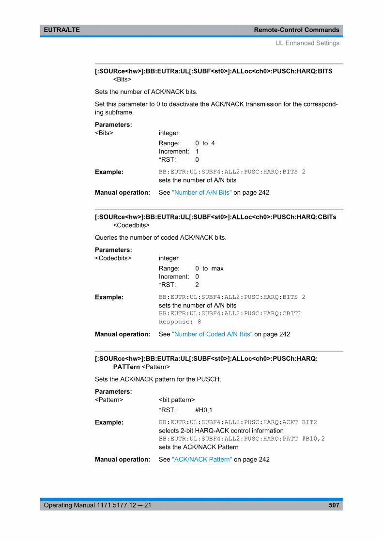
Remote-Control CommandsEUTRA/LTE
507Operating Manual 1171.5177.12 ─ 21
[:SOURce<hw>]:BB:EUTRa:UL[:SUBF<st0>]:ALLoc<ch0>:PUSCh:HARQ:BITS<Bits>
Sets the number of ACK/NACK bits.
Set this parameter to 0 to deactivate the ACK/NACK transmission for the correspond-ing subframe.
Parameters:<Bits> integer
Range: 0 to 4Increment: 1*RST: 0
Example: BB:EUTR:UL:SUBF4:ALL2:PUSC:HARQ:BITS 2sets the number of A/N bits
Manual operation: See "Number of A/N Bits" on page 242
[:SOURce<hw>]:BB:EUTRa:UL[:SUBF<st0>]:ALLoc<ch0>:PUSCh:HARQ:CBITs<Codedbits>
Queries the number of coded ACK/NACK bits.
Parameters:<Codedbits> integer
Range: 0 to maxIncrement: 0*RST: 2
Example: BB:EUTR:UL:SUBF4:ALL2:PUSC:HARQ:BITS 2sets the number of A/N bitsBB:EUTR:UL:SUBF4:ALL2:PUSC:HARQ:CBIT?Response: 8
Manual operation: See "Number of Coded A/N Bits" on page 242
[:SOURce<hw>]:BB:EUTRa:UL[:SUBF<st0>]:ALLoc<ch0>:PUSCh:HARQ:PATTern <Pattern>
Sets the ACK/NACK pattern for the PUSCH.
Parameters:<Pattern> <bit pattern>
*RST: #H0,1
Example: BB:EUTR:UL:SUBF4:ALL2:PUSC:HARQ:ACKT BIT2selects 2-bit HARQ-ACK control informationBB:EUTR:UL:SUBF4:ALL2:PUSC:HARQ:PATT #B10,2sets the ACK/NACK Pattern
Manual operation: See "ACK/NACK Pattern" on page 242
UL Enhanced Settings
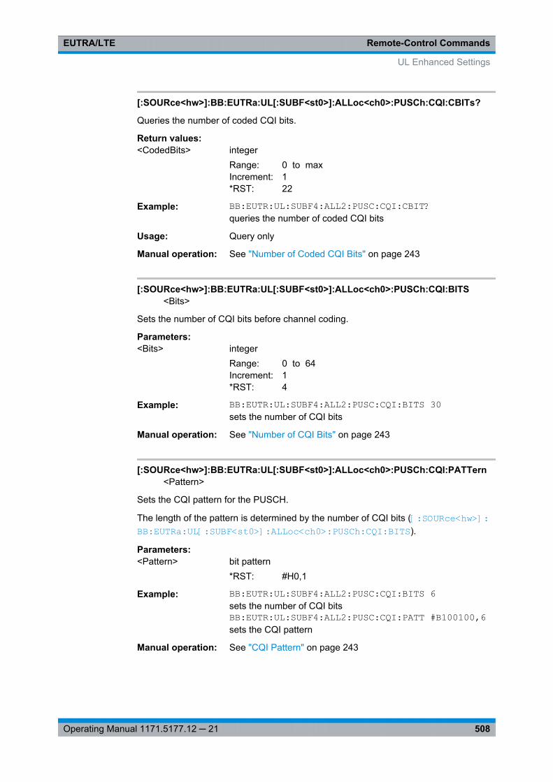
Remote-Control CommandsEUTRA/LTE
508Operating Manual 1171.5177.12 ─ 21
[:SOURce<hw>]:BB:EUTRa:UL[:SUBF<st0>]:ALLoc<ch0>:PUSCh:CQI:CBITs?
Queries the number of coded CQI bits.
Return values: <CodedBits> integer
Range: 0 to maxIncrement: 1*RST: 22
Example: BB:EUTR:UL:SUBF4:ALL2:PUSC:CQI:CBIT?queries the number of coded CQI bits
Usage: Query only
Manual operation: See "Number of Coded CQI Bits" on page 243
[:SOURce<hw>]:BB:EUTRa:UL[:SUBF<st0>]:ALLoc<ch0>:PUSCh:CQI:BITS<Bits>
Sets the number of CQI bits before channel coding.
Parameters:<Bits> integer
Range: 0 to 64Increment: 1*RST: 4
Example: BB:EUTR:UL:SUBF4:ALL2:PUSC:CQI:BITS 30sets the number of CQI bits
Manual operation: See "Number of CQI Bits" on page 243
[:SOURce<hw>]:BB:EUTRa:UL[:SUBF<st0>]:ALLoc<ch0>:PUSCh:CQI:PATTern<Pattern>
Sets the CQI pattern for the PUSCH.
The length of the pattern is determined by the number of CQI bits ([:SOURce<hw>]: BB: EUTRa: UL[:SUBF<st0>]: ALLoc<ch0>: PUSCh: CQI:BITS ).
Parameters:<Pattern> bit pattern
*RST: #H0,1
Example: BB:EUTR:UL:SUBF4:ALL2:PUSC:CQI:BITS 6sets the number of CQI bitsBB:EUTR:UL:SUBF4:ALL2:PUSC:CQI:PATT #B100100,6sets the CQI pattern
Manual operation: See "CQI Pattern" on page 243
UL Enhanced Settings
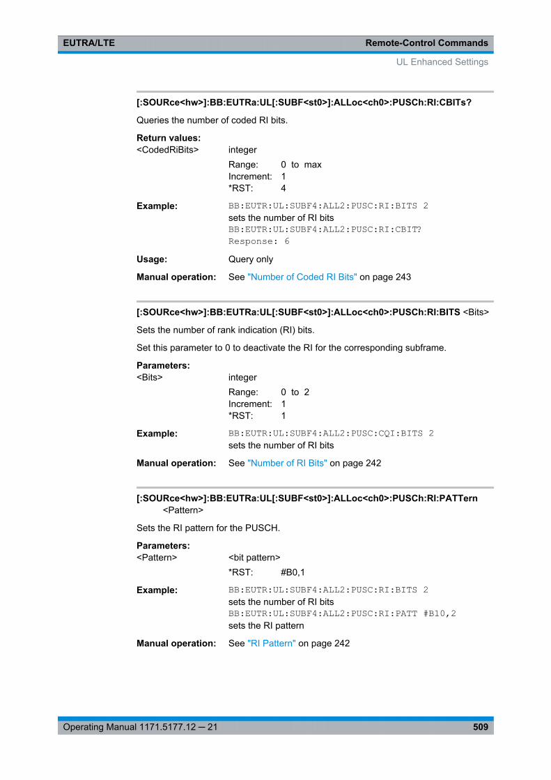
Remote-Control CommandsEUTRA/LTE
509Operating Manual 1171.5177.12 ─ 21
[:SOURce<hw>]:BB:EUTRa:UL[:SUBF<st0>]:ALLoc<ch0>:PUSCh:RI:CBITs?
Queries the number of coded RI bits.
Return values: <CodedRiBits> integer
Range: 0 to maxIncrement: 1*RST: 4
Example: BB:EUTR:UL:SUBF4:ALL2:PUSC:RI:BITS 2sets the number of RI bitsBB:EUTR:UL:SUBF4:ALL2:PUSC:RI:CBIT?Response: 6
Usage: Query only
Manual operation: See "Number of Coded RI Bits" on page 243
[:SOURce<hw>]:BB:EUTRa:UL[:SUBF<st0>]:ALLoc<ch0>:PUSCh:RI:BITS <Bits>
Sets the number of rank indication (RI) bits.
Set this parameter to 0 to deactivate the RI for the corresponding subframe.
Parameters:<Bits> integer
Range: 0 to 2Increment: 1*RST: 1
Example: BB:EUTR:UL:SUBF4:ALL2:PUSC:CQI:BITS 2sets the number of RI bits
Manual operation: See "Number of RI Bits" on page 242
[:SOURce<hw>]:BB:EUTRa:UL[:SUBF<st0>]:ALLoc<ch0>:PUSCh:RI:PATTern<Pattern>
Sets the RI pattern for the PUSCH.
Parameters:<Pattern> <bit pattern>
*RST: #B0,1
Example: BB:EUTR:UL:SUBF4:ALL2:PUSC:RI:BITS 2sets the number of RI bitsBB:EUTR:UL:SUBF4:ALL2:PUSC:RI:PATT #B10,2sets the RI pattern
Manual operation: See "RI Pattern" on page 242
UL Enhanced Settings

Remote-Control CommandsEUTRA/LTE
510Operating Manual 1171.5177.12 ─ 21
[:SOURce<hw>]:BB:EUTRa:UL[:SUBF<st0>]:ALLoc<ch0>:PUSCh:ULSCh:BITS?
Queries the number of physical bits used for UL-SCH transmission.
Return values: <PhysBitCount> integer
Range: 0 to maxIncrement: 1*RST: 1500
Example: BB:EUTR:UL:SUBF4:ALL2:PUSC:ULSC:BITS?queries the number of physical bits for UL-SCHResponse: 2000
Usage: Query only
Manual operation: See "Number of Coded UL-SCH Bits" on page 244
[:SOURce<hw>]:BB:EUTRa:UL[:SUBF<st0>]:ALLoc<ch0>:PUSCh:CCODing:TBSize <TranspBlockSize>
Sets the size of the transport block.
Parameters:<TranspBlockSize> integer
Range: 0 to 100000Increment: 1*RST: 1500
Example: BB:EUTR:UL:SUBF4:ALL2:PUSC:CCOD:TBS 1500sets the size of the transport block
Manual operation: See "Transport Block Size/Payload (PUSCH)" on page 244
[:SOURce<hw>]:BB:EUTRa:UL[:SUBF<st0>]:ALLoc<ch0>:PUSCh:CCODing:RVINdex <RedundVersIndex>
Sets the redundancy version index.
Parameters:<RedundVersIndex> integer
Range: 0 to 3Increment: 1*RST: 0
Example: BB:EUTR:UL:SUBF4:ALL2:PUSC:CCOD:RVIN 2sets the redundancy version index
Manual operation: See "Redundancy Version Index (PUSCH)" on page 244
[:SOURce<hw>]:BB:EUTRa:UL[:SUBF<st0>]:ALLoc<ch0>:PUCCh:NPAR <NPar>
Sets the resource index for PUCCH format 1/1a/1b respectively 2/2a/2b respectively 3.
UL Enhanced Settings
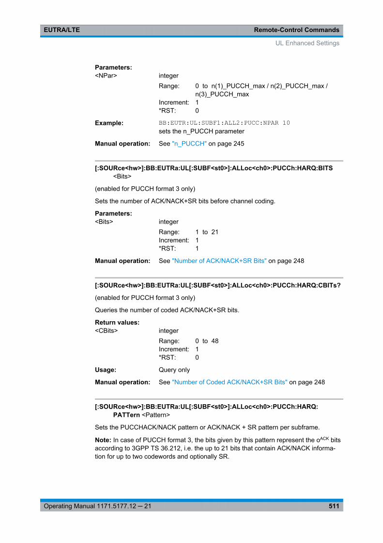
Remote-Control CommandsEUTRA/LTE
511Operating Manual 1171.5177.12 ─ 21
Parameters:<NPar> integer
Range: 0 to n(1)_PUCCH_max / n(2)_PUCCH_max /n(3)_PUCCH_max
Increment: 1*RST: 0
Example: BB:EUTR:UL:SUBF1:ALL2:PUCC:NPAR 10sets the n_PUCCH parameter
Manual operation: See "n_PUCCH" on page 245
[:SOURce<hw>]:BB:EUTRa:UL[:SUBF<st0>]:ALLoc<ch0>:PUCCh:HARQ:BITS<Bits>
(enabled for PUCCH format 3 only)
Sets the number of ACK/NACK+SR bits before channel coding.
Parameters:<Bits> integer
Range: 1 to 21Increment: 1*RST: 1
Manual operation: See "Number of ACK/NACK+SR Bits" on page 248
[:SOURce<hw>]:BB:EUTRa:UL[:SUBF<st0>]:ALLoc<ch0>:PUCCh:HARQ:CBITs?
(enabled for PUCCH format 3 only)
Queries the number of coded ACK/NACK+SR bits.
Return values: <CBits> integer
Range: 0 to 48Increment: 1*RST: 0
Usage: Query only
Manual operation: See "Number of Coded ACK/NACK+SR Bits" on page 248
[:SOURce<hw>]:BB:EUTRa:UL[:SUBF<st0>]:ALLoc<ch0>:PUCCh:HARQ:PATTern <Pattern>
Sets the PUCCHACK/NACK pattern or ACK/NACK + SR pattern per subframe.
Note: In case of PUCCH format 3, the bits given by this pattern represent the oACK bitsaccording to 3GPP TS 36.212, i.e. the up to 21 bits that contain ACK/NACK informa-tion for up to two codewords and optionally SR.
UL Enhanced Settings
Remote-Control CommandsEUTRA/LTE
512Operating Manual 1171.5177.12 ─ 21
To enable the generation of signal with ACK/NACK information that vary not only persubframe but also differs over the frames, set an ACK/NACK pattern with more than 1bit for the PUCCH formats 1a/2a, respectively 2 bits for formats 1b/2b, respectively"Number of ACK/NACK + SR Bits" for format 3.
The ACK/NACK pattern has a maximal length of 32 bits and is read out cyclically.
Parameters:<Pattern> <32-bit pattern>
*RST: #H0,1
Example: BB:EUTR:UL:SUBF4:ALL2:PUCC:HARQ:PATT #B10,2sets the ACK/NACK Pattern
Manual operation: See "ACK/NACK Pattern / ACK/NACK+SR Pattern"on page 246
[:SOURce<hw>]:BB:EUTRa:UL[:SUBF<st0>]:ALLoc<ch0>:PUCCh:CQI:CBITs?
Queries the number of coded CQI bits.
Return values: <CodedBits> integer
Range: 0 to maxIncrement: 1*RST: 20
Example: BB:EUTR:UL:SUBF4:ALL2:PUCC:CQI:CBIT?queries sets the number of coded CQI bitsResponse: 20The number of coded CQI bits for PUCCH is always 20.
Usage: Query only
Manual operation: See "Number of Coded CQI Bits (PUCCH)" on page 248
[:SOURce<hw>]:BB:EUTRa:UL[:SUBF<st0>]:ALLoc<ch0>:PUCCh:CQI:BITS<Bits>
Sets the number of CQI bits before channel coding.
Parameters:<Bits> integer
Range: 0 to maxIncrement: 1*RST: 4
Example: BB:EUTR:UL:SUBF4:ALL2:PUCC:CQI:BITS 30sets the number of CQI bits
Manual operation: See "Number of CQI Bits (PUCCH)" on page 247
UL Enhanced Settings
Remote-Control CommandsEUTRA/LTE
513Operating Manual 1171.5177.12 ─ 21
[:SOURce<hw>]:BB:EUTRa:UL[:SUBF<st0>]:ALLoc<ch0>:PUCCh:CQI:PATTern<Pattern>
Sets the CQI pattern for the PUCCH.
The length of the pattern is determined by the number of CQI bits(BB:EUTR:UL:SUBF:ALL:PUCC:CQI:BITS).
Parameters:<Pattern> <bit pattern>
*RST: #B0,1
Example: BB:EUTR:UL:SUBF4:ALL2:PUCC:CQI:BITS 6sets the number of CQI bitsBB:EUTR:UL:SUBF4:ALL2:PUCC:CQI:PATT #B100100,6sets the CQI pattern
Manual operation: See "CQI Pattern (PUCCH)" on page 248
9.18 Configure User
[:SOURce<hw>]:BB:EUTRa:DL:USER<ch>:STATe...........................................................513[:SOURce<hw>]:BB:EUTRa:DL:USER<ch>:CA:STATe......................................................514[:SOURce<hw>]:BB:EUTRa:DL:USER<ch>:TXM.............................................................. 514[:SOURce<hw>]:BB:EUTRa:DL:USER<ch>:CELL<st0>:TXM............................................. 514[:SOURce<hw>]:BB:EUTRa:DL:USER<ch>:UEC.............................................................. 514[:SOURce<hw>]:BB:EUTRa:DL:USER<ch>:APM:CBINdex[<dir>]....................................... 515[:SOURce<hw>]:BB:EUTRa:DL:USER<ch>:APM:MAPCoordinates.....................................515[:SOURce<hw>]:BB:EUTRa:DL:USER<ch>:APM:MODE................................................... 515[:SOURce<hw>]:BB:EUTRa:DL:USER<ch>:APM:AP<dir0>:BB<st0>:REAL.........................516[:SOURce<hw>]:BB:EUTRa:DL:USER<ch>:APM:AP<dir0>:BB<st0>:IMAGinary.................. 516[:SOURce<hw>]:BB:EUTRa:DL:USER<ch>:SCRambling:STATe........................................516[:SOURce<hw>]:BB:EUTRa:DL:USER<ch>:CCODing:STATe............................................ 517[:SOURce<hw>]:BB:EUTRa:DL:USER<ch>:UEID............................................................. 517[:SOURce<hw>]:BB:EUTRa:DL:USER<ch>:DATA............................................................ 517[:SOURce<hw>]:BB:EUTRa:DL:USER<ch>:DSELect........................................................ 518[:SOURce<hw>]:BB:EUTRa:DL:USER<ch>:PATTern........................................................ 518[:SOURce<hw>]:BB:EUTRa:DL:USER<ch>:PA.................................................................518[:SOURce<hw>]:BB:EUTRa:DL:USER<ch>:ASRS:STATe................................................. 519[:SOURce<hw>]:BB:EUTRa:DL:USER<ch>:CAW:STATe...................................................519
[:SOURce<hw>]:BB:EUTRa:DL:USER<ch>:STATe <UserState>
Enables/disables an user.
Parameters:<UserState> 0 | 1 | OFF | ON
*RST: 1
Example: SOURce1:BB:EUTRa:DL:USER1:STATe OFF
Configure User
Remote-Control CommandsEUTRA/LTE
514Operating Manual 1171.5177.12 ─ 21
Manual operation: See "State" on page 178
[:SOURce<hw>]:BB:EUTRa:DL:USER<ch>:CA:STATe <State>
Enables/disables carrier aggregation for the selected user.
Parameters:<State> 0 | 1 | OFF | ON
*RST: 0
Options: R&S SMx/AMU-K85
Manual operation: See "Activate CA" on page 181
[:SOURce<hw>]:BB:EUTRa:DL:USER<ch>:TXM <TxMode>
Sets the transmission mode of the according user as defined in 3GPP TS 36.213, sec-tion 7.1.
Parameters:<TxMode> USER | M1 | M2 | M3 | M4 | M5 | M6 | M7 | M8 | M9
*RST: USER
Example: SOURce1:BB:EUTRa:DL:USER1:TXM M7Options: Tx Mode 8 and Tx Mode 9 require R&S SMx/AMU-K84/-K284
and R&S SMx/AMU-K85/-K285 respectively
Manual operation: See "Tx Mode(s)" on page 179
[:SOURce<hw>]:BB:EUTRa:DL:USER<ch>:CELL<st0>:TXM <TxMode>
Sets the transmission mode of the user per cell.
Suffix: <st0>
.0 .. 4Identifies the cell: 0 = primary cell, 1 .. 4 = SCell1 .. SCell4
Parameters:<TxMode> USER | M1 | M2 | M3 | M4 | M5 | M6 | M7 | M8 | M9
*RST: USER
Example: SOURce1:BB:EUTRa:DL:USER1:CELL0:TXM M9SOURce1:BB:EUTRa:DL:USER1:CELL1:TXM M7
Manual operation: See "Tx Mode(s)" on page 179
[:SOURce<hw>]:BB:EUTRa:DL:USER<ch>:UEC <UECategory>
Sets the UE Category.
Configure User
Remote-Control CommandsEUTRA/LTE
515Operating Manual 1171.5177.12 ─ 21
Parameters:<UECategory> USER | C1 | C2 | C3 | C5 | C4
*RST: USER
Manual operation: See "UE Category" on page 179
[:SOURce<hw>]:BB:EUTRa:DL:USER<ch>:APM:CBINdex[<dir>]<CodeBookIndex>
Sets the codebook index for mapping mode Codebook.
Suffix: <dir>
.1|2In TxMode 9, determines the codebook index
Parameters:<CodeBookIndex> integer
Range: 0 to 15Increment: 1*RST: 0
Example: SOURce1:BB:EUTRa:DL:USER1:APM:MODE CBSOURce1:BB:EUTRa:DL:USER1:APM:CBINdex1 5
Options: R&S SMx/AMU-K84/-K284
Manual operation: See "Codebook Index/Codebook Index 2" on page 185
[:SOURce<hw>]:BB:EUTRa:DL:USER<ch>:APM:MAPCoordinates <MapCoord>
Switches between the Cartesian (Real/Imag.) and Cylindrical (Magn./Phase) coordi-nates representation.
Parameters:<MapCoord> CARTesian | CYLindrical
*RST: CART
Options: R&S SMx/AMU-K84/-K284
Manual operation: See "Mapping Coordinates" on page 185
[:SOURce<hw>]:BB:EUTRa:DL:USER<ch>:APM:MODE <AntPortMap>
Defines the antenna port mapping method, see "Mapping Methods" on page 183.
Configure User
Remote-Control CommandsEUTRA/LTE
516Operating Manual 1171.5177.12 ─ 21
Parameters:<AntPortMap> CB | RCB | FW
CBCodebookRCBRandom codebookFWFixed weight*RST: FW
Options: R&S SMx/AMU-K84/-K284
Manual operation: See "Antenna Port Mapping" on page 185
[:SOURce<hw>]:BB:EUTRa:DL:USER<ch>:APM:AP<dir0>:BB<st0>:REAL<AntPortMapData>
[:SOURce<hw>]:BB:EUTRa:DL:USER<ch>:APM:AP<dir0>:BB<st0>:IMAGinary<AntPortMapData>
Defines the mapping of the antenna ports to the physical antennas.
Suffix: <dir0>
.5 | 7 | .. 14antenna port
<st0> 1 to 4available basebands
Parameters:<AntPortMapData> float
Range: -1 to 1Increment: 0.01*RST: 0
Manual operation: See "Mapping table" on page 185
[:SOURce<hw>]:BB:EUTRa:DL:USER<ch>:SCRambling:STATe <State>
Enables/disables scrambling for all allocations belonging to the selected user.
In the allocation table, the scrambling state of all allocations for which User 1...4 isselected as "Data Source" is set to the value set with this parameter.
Parameters:<State> 0 | 1 | OFF | ON
*RST: ON
Configure User
Remote-Control CommandsEUTRA/LTE
517Operating Manual 1171.5177.12 ─ 21
Example: SOUR:BB:EUTR:DL:USER3:SCR:STAT OFFdisables scrambling for allocations belonging to user 3.SOUR:BB:EUTR:DL:SUBF0:ALL4:CW:DATA USER3SOUR:BB:EUTR:DL:SUBF0:ALL5:CW:DATA USER3SOUR:BB:EUTR:DL:SUBF0:ALL4:CW:SCR:STAT?Response: OffSOUR:BB:EUTR:DL:SUBF0:ALL5:CW:SCR:STAT?Response: Off
Manual operation: See "Scrambling State" on page 179
[:SOURce<hw>]:BB:EUTRa:DL:USER<ch>:CCODing:STATe <State>
Enables/disables channel coding for all allocations belonging to the selected user.
In the allocation table, the Channel Coding State of all allocations for which User 1...4is selected as "Data Source" is set to the value set with this parameter.
Parameters:<State> 0 | 1 | OFF | ON
*RST: OFF
Example: BB:EUTR:DL:USER2:CCOD:STAT ONenables channel coding for allocations belonging to user 2.
Manual operation: See "Channel Coding State" on page 179
[:SOURce<hw>]:BB:EUTRa:DL:USER<ch>:UEID <Ueid>
Sets the user equipment ID.
Parameters:<Ueid> integer
Range: 0 to 65535Increment: 1*RST: 0
Example: BB:EUTR:DL:USER2:UEID 3308sets the UE ID.
Manual operation: See "UE ID" on page 180
[:SOURce<hw>]:BB:EUTRa:DL:USER<ch>:DATA <Data>
Selects the data source for the selected user configuration.
Parameters:<Data> PN9 | PN11 | PN15 | PN16 | PN20 | PN21 | PN23 | PATTern |
DLISt | ZERO | ONE*RST: PN9
Example: BB:EUTR:DL:USER2:DATA PN9PN9 is selected as data source for the user configuration.
Configure User
Remote-Control CommandsEUTRA/LTE
518Operating Manual 1171.5177.12 ─ 21
Manual operation: See "Data List Management" on page 75
[:SOURce<hw>]:BB:EUTRa:DL:USER<ch>:DSELect <DSelect>
Selects the data list for the DLISt data source selection.
The lists are stored as files with the fixed file extensions *.dm_iqd in a directory of theuser's choice. The directory applicable to the following commands is defined with thecommand MMEMory:CDIR. To access the files in this directory, you only have to givethe file name, without the path and the file extension.
Parameters:<DSelect> string
Example: BB:EUTR:DL:USER2:DATA DLISselects the Data Lists data source.MMEM:CDIR '<root>Lists'selects the directory for the data lists.BB:EUTR:DL:USER2:DSEL 'eutra_list1'selects file eutra_list1 as the data source. This file must bein the directory <root>Lists and have the file extension*.dm_iqd.
Manual operation: See "Data List Management" on page 75
[:SOURce<hw>]:BB:EUTRa:DL:USER<ch>:PATTern <Pattern>
Selects the bit pattern for the PATT selection. The maximum length is 64 bits.
Parameters:<Pattern> <64-bit pattern>
*RST: #H0,1
Example: BB:EUTR:DL:USER2:PATT #H3F,8defines the bit pattern.
Manual operation: See "Data Source, DList/Pattern" on page 180
[:SOURce<hw>]:BB:EUTRa:DL:USER<ch>:PA <Power>
Sets PDSCH power factor according to 3GPP TS 36.213, chapter 5.2.
Parameters:<Power> -6.02 | -4.77 | -3.01 | -1.77 | 0 | 0.97 | 2.04 | 3.01
Range: -6.02 to 3.01*RST: 0
Example: BB:EUTR:DL:USER2:PA 2.04selects the P_A
Manual operation: See "P_A" on page 180
Configure User
Remote-Control CommandsEUTRA/LTE
519Operating Manual 1171.5177.12 ─ 21
[:SOURce<hw>]:BB:EUTRa:DL:USER<ch>:ASRS:STATe <CuApSrsState>
Enabes/disables an aperiodic transmission of SRS for the selected user.
Parameters:<CuApSrsState> 0 | 1 | OFF | ON
*RST: 0
Example: SOURce1:BB:EUTRa:DL:USER2:ASRS:STATe ONManual operation: See "Aperiodic SRS" on page 181
[:SOURce<hw>]:BB:EUTRa:DL:USER<ch>:CAW:STATe <CuCsiAware>
Enables/disables the CSI awareness for the selected user.
Parameters:<CuCsiAware> OFF | ON | 1 | 0
*RST: OFF
Example: see example "Enabling a CSI-RS transmission" on page 453
Manual operation: See "CSI Awareness" on page 181
9.19 Dummy Data Configuration
[:SOURce<hw>]:BB:EUTRa:DL:DUMD:MODulation.......................................................... 519[:SOURce<hw>]:BB:EUTRa:DL:DUMD:POWer.................................................................519[:SOURce<hw>]:BB:EUTRa:DL:DUMD:DATA...................................................................520[:SOURce<hw>]:BB:EUTRa:DL:DUMD:DSELect...............................................................520[:SOURce<hw>]:BB:EUTRa:DL:DUMD:PATTern...............................................................520[:SOURce<hw>]:BB:EUTRa:DL:DUMD:OPSubframes....................................................... 521
[:SOURce<hw>]:BB:EUTRa:DL:DUMD:MODulation <Modulation>
Selects modulation for dummy data.
Parameters:<Modulation> QPSK | QAM16 | QAM64
*RST: QPSK
Example: BB:EUTR:DL:DUMD:MOD QAM16QAM16 is selected as modulation for dummy data.
Manual operation: See "Modulation" on page 191
[:SOURce<hw>]:BB:EUTRa:DL:DUMD:POWer <Power>
Sets the power for dummy data.
Dummy Data Configuration
Remote-Control CommandsEUTRA/LTE
520Operating Manual 1171.5177.12 ─ 21
Parameters:<Power> float
Range: -80.00 dB to 10.00 dBIncrement: 0.001 dB*RST: 0 dB
Example: BB:EUTR:DL:DUMD:POWer 10.00sets the power for dummy data to 10 dB.
Manual operation: See "Power (Dummy Data)" on page 191
[:SOURce<hw>]:BB:EUTRa:DL:DUMD:DATA <Data>
Selects the data source for dummy data.
Parameters:<Data> PN9 | PN11 | PN15 | PN16 | PN20 | PN21 | PN23 | PATTern |
DLISt | ZERO | ONE*RST: PN9
Example: BB:EUTR:DL:DUMD:DATA PN9PN9 is selected as data source for dummy data.
Manual operation: See "Data Source" on page 191
[:SOURce<hw>]:BB:EUTRa:DL:DUMD:DSELect <Filename>
Selects the data list for the DLISt data source selection.
The lists are stored as files with the fixed file extensions *.dm_iqd in a directory ofthe user's choice. The directory applicable to the following commands is defined withthe command MMEMory:CDIR. To access the files in this directory, you only have togive the file name, without the path and the file extension.
Parameters:<Filename> string
Example: BB:EUTR:DL:DUMD:DATA DLISselects the Data Lists data source.MMEM:CDIR '<root>Lists'selects the directory for the data lists.BB:EUTR:DL:DUMD:DSELect 'eutra_list1'selects file eutra_list1 as the data source. This file must bein the directory <root>Lists and have the file extension*.dm_iqd.
Manual operation: See "Data Source" on page 191
[:SOURce<hw>]:BB:EUTRa:DL:DUMD:PATTern <Pattern>
Selects the bit pattern for the PATTern selection. The maximum length is 64 bits.
Dummy Data Configuration
Remote-Control CommandsEUTRA/LTE
521Operating Manual 1171.5177.12 ─ 21
Parameters:<Pattern> <bit pattern>
*RST: #H0,1
Example: BB:EUTR:DL:DUMD:PATTern #H1E,8defines the bit pattern to #H1E,8.
Manual operation: See "Data Source" on page 191
[:SOURce<hw>]:BB:EUTRa:DL:DUMD:OPSubframes <OmitPrsSf>
If the OCNG is used, you can disable (omit) the OCNG transmission in the non-mutedPRS subframes.
Parameters:<OmitPrsSf> 0 | 1 | OFF | ON
*RST: 0
Example: SOURce1:BB:EUTRa:DL:BUR DUDataSOURce1:BB:EUTRa:DL:PRSS:MIPattern #H2,2SOURce1:BB:EUTRa:DL:DUMD:OPSubframes ON
Manual operation: See "Omit PRS Subframes" on page 192
9.20 SPS Configuration
[:SOURce<hw>]:BB:EUTRa:DL:USER<ch>:SPS:STATe <UsrSpsState>
Enables SPS (semi-persistence scheduling).
Parameters:<UsrSpsState> 0 | 1 | OFF | ON
*RST: 0
Example: SOURce1:BB:EUTRa:DL:USER2:SPS:STATe ONSOURce1:BB:EUTRa:DL:USER2:SPS:CRNTi 250SOURce1:BB:EUTRa:DL:USER2:SPS:SINTerval S20SOURce1:BB:EUTRa:DL:USER2:SPS:SACTivation 1SOURce1:BB:EUTRa:DL:USER2:SPS:SRELease 3
Manual operation: See "Activate SPS" on page 189
[:SOURce<hw>]:BB:EUTRa:DL:USER<ch>:SPS:CRNTi <UserSpsCRnti>
Sets the SPS C-RNTI parameter.
Parameters:<UserSpsCRnti> integer
Range: 1 to 65523Increment: 1*RST: 0
SPS Configuration
Remote-Control CommandsEUTRA/LTE
522Operating Manual 1171.5177.12 ─ 21
Example: see [:SOURce<hw>]: BB:EUTRa:DL: USER<ch>: SPS:STATeon page 521
Manual operation: See "SPS C-RNTI" on page 190
[:SOURce<hw>]:BB:EUTRa:DL:USER<ch>:SPS:SINTerval <UserSpsInt>
Defines the SPS interval.
Parameters:<UserSpsInt> S10 | S20 | S32 | S40 | S64 | S80 | S128 | S160 | S320 | S640
*RST: S10
Example: see [:SOURce<hw>]: BB:EUTRa:DL: USER<ch>: SPS:STATeon page 521
Manual operation: See "SPS Interval" on page 190
[:SOURce<hw>]:BB:EUTRa:DL:USER<ch>:SPS:SACTivation <UsrSpsActSubfr>[:SOURce<hw>]:BB:EUTRa:DL:USER<ch>:SPS:SRELease <UsrSpsRelSubfr>
Defines the start and end subframes of the semi-persistent scheduling.
Parameters:<UsrSpsRelSubfr> integer
Range: 0 to 65535*RST: 0
Example: see [:SOURce<hw>]: BB:EUTRa:DL: USER<ch>: SPS:STATeon page 521
Manual operation: See "Activation/Release Subframe No" on page 190
9.21 User Equipment
[:SOURce<hw>]:BB:EUTRa:UL:UE<st>:RELease............................................................. 523[:SOURce<hw>]:BB:EUTRa:UL:UE<st>:DACRestart......................................................... 523[:SOURce<hw>]:BB:EUTRa:UL:UE<st>:ID....................................................................... 524[:SOURce<hw>]:BB:EUTRa:UL:UE<st>:STATe................................................................ 524[:SOURce<hw>]:BB:EUTRa:UL:UE<st>:MODE.................................................................524[:SOURce<hw>]:BB:EUTRa:UL:UE<st>:POWer................................................................525[:SOURce<hw>]:BB:EUTRa:UL:UE<st>:FRC:ALRB.......................................................... 525[:SOURce<hw>]:BB:EUTRa:UL:UE<st>:FRC:MODulation..................................................525[:SOURce<hw>]:BB:EUTRa:UL:UE<st>:FRC:N2DMrs....................................................... 526[:SOURce<hw>]:BB:EUTRa:UL:UE<st>:FRC:PASize?...................................................... 526[:SOURce<hw>]:BB:EUTRa:UL:UE<st>:FRC:STATe.........................................................526[:SOURce<hw>]:BB:EUTRa:UL:UE<st>:FRC:TNOBits?.....................................................527[:SOURce<hw>]:BB:EUTRa:UL:UE<st>:FRC:TYPE.......................................................... 527[:SOURce<hw>]:BB:EUTRa:UL:UE<st>:FRC:VRBoffset.................................................... 528[:SOURce<hw>]:BB:EUTRa:UL:UE<st>:PRACh:PRSTate..................................................528
User Equipment
Remote-Control CommandsEUTRA/LTE
523Operating Manual 1171.5177.12 ─ 21
[:SOURce<hw>]:BB:EUTRa:UL:UE<st>:PRACh:PRTT...................................................... 528[:SOURce<hw>]:BB:EUTRa:UL:UE<st>:PRACh:PRFormat................................................ 529[:SOURce<hw>]:BB:EUTRa:UL:UE<st>:PRACh:CFRames................................................ 529[:SOURce<hw>]:BB:EUTRa:UL:UE<st>:PRACh:SUBF<ch0>:RBOFfset.............................. 529[:SOURce<hw>]:BB:EUTRa:UL:UE<st>:PRACh:SUBF<ch0>:FRINdex............................... 530[:SOURce<hw>]:BB:EUTRa:UL:UE<st>:PRACh:SUBF<ch0>:POWer..................................530[:SOURce<hw>]:BB:EUTRa:UL:UE<st>:PRACh:SUBF<ch0>:NCSConf...............................530[:SOURce<hw>]:BB:EUTRa:UL:UE<st>:PRACh:SUBF<ch0>:RSEQuence.......................... 531[:SOURce<hw>]:BB:EUTRa:UL:UE<st>:PRACh:SUBF<ch0>:SINDex................................. 531[:SOURce<hw>]:BB:EUTRa:UL:UE<st>:PRACh:SUBF<ch0>:DT........................................531[:SOURce<hw>]:BB:EUTRa:UL:UE<st>:PRACh:SUBF<ch0>:STATe.................................. 531[:SOURce<hw>]:BB:EUTRa:UL:UE<st>:PUSCh:DATA...................................................... 532[:SOURce<hw>]:BB:EUTRa:UL:UE<st>:PUSCh:PATTern..................................................532[:SOURce<hw>]:BB:EUTRa:UL:UE<st>:PUSCh:DSELect..................................................532[:SOURce<hw>]:BB:EUTRa:UL:UE<st>:PUSCh:SCRambling:STATe..................................533[:SOURce<hw>]:BB:EUTRa:UL:UE<st>:PUSCh:CCODing:STATe......................................533[:SOURce<hw>]:BB:EUTRa:UL:UE<st>:PUSCh:CCODing:MODE...................................... 533[:SOURce<hw>]:BB:EUTRa:UL:UE<st>:PUSCh:CCODing:INTerleaver............................... 534[:SOURce<hw>]:BB:EUTRa:UL:UE<st>:PUSCh:CCODing:ICQioffset..................................534[:SOURce<hw>]:BB:EUTRa:UL:UE<st>:PUSCh:CCODing:IHARqoffset...............................535[:SOURce<hw>]:BB:EUTRa:UL:UE<st>:PUSCh:CCODing:IRIoffset....................................535[:SOURce<hw>]:BB:EUTRa:UL:UE<st>:PUSCh:CCODing:OCQimin...................................535[:SOURce<hw>]:BB:EUTRa:UL:UE<st>:REFSig:DRS:POWoffset....................................... 536[:SOURce<hw>]:BB:EUTRa:UL:UE<st>:REFSig:SRS:STATe.............................................536[:SOURce<hw>]:BB:EUTRa:UL:UE<st>:REFSig:SRS:POWoffset....................................... 536[:SOURce<hw>]:BB:EUTRa:UL:UE<st>:REFSig:SRS:CYCShift..........................................536[:SOURce<hw>]:BB:EUTRa:UL:UE<st>:REFSig:SRS:BHOP..............................................537[:SOURce<hw>]:BB:EUTRa:UL:UE<st>:REFSig:SRS:BSRS.............................................. 537[:SOURce<hw>]:BB:EUTRa:UL:UE<st>:REFSig:SRS:ISRS............................................... 537[:SOURce<hw>]:BB:EUTRa:UL:UE<st>:REFSig:SRS:TSRS.............................................. 538[:SOURce<hw>]:BB:EUTRa:UL:UE<st>:REFSig:SRS:TOFFset?........................................ 538[:SOURce<hw>]:BB:EUTRa:UL:UE<st>:REFSig:SRS:TRComb..........................................539[:SOURce<hw>]:BB:EUTRa:UL:UE<st>:REFSig:SRS:NRRC............................................. 539
[:SOURce<hw>]:BB:EUTRa:UL:UE<st>:RELease <Release>
Determines whether the selected UE is a LTE Release 8/9 or LTE Release 10 UE.
Parameters:<Release> R89 | R10
*RST: R89
Options: R&S SMx/AMU-K85
Manual operation: See "3GPP Release" on page 217
[:SOURce<hw>]:BB:EUTRa:UL:UE<st>:DACRestart <State>
If activated, the data source, the ACK/NACK pattern, the CQI pattern and RI are restar-ted every subframe.
User Equipment
Remote-Control CommandsEUTRA/LTE
524Operating Manual 1171.5177.12 ─ 21
Parameters:<State> 0 | 1 | OFF | ON
*RST: OFF
Example: BB:EUTR:UL:UE2:PUSC:DACR ONenables restarting of the data source every subframe
Manual operation: See "Restart Data, A/N, CQI and RI every subframe"on page 217
[:SOURce<hw>]:BB:EUTRa:UL:UE<st>:ID <Id>
Sets the radio network temporary identifier (RNTI) of the UE.
Parameters:<Id> integer
Range: 0 to 65535Increment: 1*RST: 0
Example: BB:EUTR:UL:UE3:ID 303sets the UE ID
Manual operation: See "UE ID/n_RNTI (User Equipment)" on page 217
[:SOURce<hw>]:BB:EUTRa:UL:UE<st>:STATe <State>
Selects the user equipment state.
Parameters:<State> 0 | 1 | OFF | ON
*RST: ON (UE1); OFF (UE2..UE4)
Example: BB:EUTR:UL:UE2:STAT ONactivates UE2.
Manual operation: See "State (User Equipment)" on page 216
[:SOURce<hw>]:BB:EUTRa:UL:UE<st>:MODE <Mode>
Selects whether the user equipment is in standard or in PRACH mode.
Parameters:<Mode> STD | PRACh
*RST: STD
Example: BB:EUTR:UL:UE:MODE STDselects the standard mode for UE1.
Manual operation: See "Mode" on page 217
User Equipment
Remote-Control CommandsEUTRA/LTE
525Operating Manual 1171.5177.12 ─ 21
[:SOURce<hw>]:BB:EUTRa:UL:UE<st>:POWer <Power>
Sets the power level of the selected UE.
Parameters:<Power> float
Range: -80.00 to 10.00Increment: 0.001*RST: 0
Example: BB:EUTR:UL:UE2:POW -5.0sets the power of UE2
Manual operation: See "UE Power" on page 217
[:SOURce<hw>]:BB:EUTRa:UL:UE<st>:FRC:ALRB <AllocResBlocks>
Queries the number of the allocated resource blocks for the selected FRC ([:SOURce<hw>]: BB:EUTRa:UL: UE<st>:FRC: TYPE on page 527). For FRCs A.2.2.2.1 and A.2.2.2.2 this parameter can also be set to different values according to3GPP TS 36.521-1.
Parameters:<AllocResBlocks> integer
Range: 0 to 110Increment: 1*RST: 0
Example: BB:EUTR:UL:UE2:FRC:TYPE A34sets the FRCBB:EUTR:UL:UE2:FRC:ALRB?Response: 25
Manual operation: See "Allocated Resource Blocks" on page 220
[:SOURce<hw>]:BB:EUTRa:UL:UE<st>:FRC:MODulation <Modulation>
Queries the modulation for the selected FRC ([:SOURce<hw>]: BB:EUTRa: UL:UE<st>: FRC:TYPE on page 527).
Parameters:<Modulation> QPSK | QAM16 | QAM64
*RST: QPSK
Example: BB:EUTR:UL:UE2:FRC:TYPE A34sets the FRCBB:EUTR:UL:UE2:FRC:MOD?Response: QPSK
User Equipment
Remote-Control CommandsEUTRA/LTE
526Operating Manual 1171.5177.12 ─ 21
[:SOURce<hw>]:BB:EUTRa:UL:UE<st>:FRC:N2DMrs <N2Dmrs>
Sets the UE specific part of the demodulation reference signal (DMRS) index for allPUSCH allocation of the selected UE in all subframes.
n(2)_DMRS set for the individual subframes with the command [:SOURce<hw>]: BB:EUTRa: UL[:SUBF<st0>]: ALLoc<ch0>: PUSCh:NDMRs for the corresponding UE isoverwritten.
Parameters:<N2Dmrs> integer
Range: 0 to 11Increment: 1*RST: 0
Example: SOUR:BB:EUTR:UL:SUBF4:ALL0:PUSC:NDMR 3sets the n(2)_DMRSSOUR:BB:EUTR:UL:UE1:FRC:STAT ONenables FRCSOUR:BB:EUTR:UL:UE1:FRC:N2DM 5sets the DMRS index for all PUSCH allocation of the selectedUE in all subframesSOUR:BB:EUTR:UL:SUBF4:ALL0:PUSH:N2DM?Response: 5
Manual operation: See "n(2)_DMRS (FRC)" on page 220
[:SOURce<hw>]:BB:EUTRa:UL:UE<st>:FRC:PASize?
Queries the payload size for the selected FRC ([:SOURce<hw>]: BB:EUTRa:UL: UE<st>:FRC: TYPE on page 527).
Return values: <PayloadSize> integer
Range: 0 to 200000Increment: 1*RST: 0
Example: BB:EUTR:UL:UE2:FRC:TYPE A34sets the FRCBB:EUTR:UL:UE2:FRC:PAS?Response: 2216
Usage: Query only
Manual operation: See "Payload Size (FRC)" on page 220
[:SOURce<hw>]:BB:EUTRa:UL:UE<st>:FRC:STATe <State>
Enables/disables FRC configuration.
User Equipment
Remote-Control CommandsEUTRA/LTE
527Operating Manual 1171.5177.12 ─ 21
Enabling FRC configuration sets some parameters to their predefined values, i.e. sev-eral parameters are displayed as read-only. Reconfiguration of the values of thisparameters is possible only after disabling the FRC configuration.
The FRC State is disabled and can not be enabled, if a user defined cyclic prefix(BB:EUTR:UL:CPC USER) is selected.
Parameters:<State> 0 | 1 | OFF | ON
*RST: OFF
Example: BB:EUTR:UL:UE2:FRC:STAT ONenables FRC
Manual operation: See "FRC State" on page 218
[:SOURce<hw>]:BB:EUTRa:UL:UE<st>:FRC:TNOBits?
Queries the total number of physical bits available for the PUSCH allocation per sub-frame in case the PUSCH is not shortened because of SRS or bcause it is transmittedin a cell specific SRS subframe.
Return values: <TotalBitCount> integer
Range: 0 to maxIncrement: 1*RST: 0
Example: BB:EUTR:UL:UE2:FRC:TYPE A34sets the FRCBB:EUTR:UL:UE2:FRC:TNOB?Response: 7200
Usage: Query only
Manual operation: See "Physical Bits Per Subframe (Unshortened PUSCH)"on page 220
[:SOURce<hw>]:BB:EUTRa:UL:UE<st>:FRC:TYPE <Type>
Selects a predefined fixed reference channel according to 3GPP TS 36.141, Annex A,respectively 3GPP TS 36.521-1, Annex A.
Parameters:<Type> A11 | A12 | A13 | A14 | A15 | A21 | A22 | A23 | A31 | A32 | A33 |
A34 | A35 | A36 | A37 | A41 | A42 | A43 | A44 | A45 | A46 | A47 |A48 | A51 | A52 | A53 | A54 | A55 | A56 | A57 | A71 | A72 | A73 |A74 | A75 | A76 | A81 | A82 | A83 | A84 | A85 | A86 | UE11 |UE12 | UE21 | UE22 | UE3*RST: A11
Example: BB:EUTR:UL:UE2:FRC:TYPE A34selects FRC A3_4
User Equipment
Remote-Control CommandsEUTRA/LTE
528Operating Manual 1171.5177.12 ─ 21
Manual operation: See "FRC" on page 219
[:SOURce<hw>]:BB:EUTRa:UL:UE<st>:FRC:VRBoffset <VrbOffset>
Sets the virtual resource block (VRB) offset for all PUSCH allocation of the selectedUE in all subframes.
VRB Offset set for the individual subframes with the command [:SOURce<hw>]: BB:EUTRa: UL[:SUBF<st0>]: ALLoc<ch0>: VRBoffset are overwritten.
Parameters:<VrbOffset> integer
Range: 0 to maxIncrement: 1*RST: 2
Example: SOUR:BB:EUTR:UL:SUBF4:ALL0:VRB 6SOUR:BB:EUTR:UL:UE1:FRC:STAT ONSOUR:BB:EUTR:UL:UE1:FRC:VRB 3SOUR:BB:EUTR:UL:SUBF4:ALL0:VRB?Response: 3
Manual operation: See "Offset VRB (FRC)" on page 220
[:SOURce<hw>]:BB:EUTRa:UL:UE<st>:PRACh:PRSTate <State>
Activates Power Ramping for the PRACH preamble. The start and the end of the pre-amble is cyclically extended and multiplied with a ramping function (sin^2).
Parameters:<State> 0 | 1 | OFF | ON
*RST: OFF
Example: BB:EUTR:UL:UE1:MODE PRACBB:EUTR:UL:UE1:PRAC:PRST ON
Manual operation: See "State PRACH Power Ramping" on page 237
[:SOURce<hw>]:BB:EUTRa:UL:UE<st>:PRACh:PRTT <TransitionTime>
Defines the transition time from beginning of the extended preamble to the start of thepreamble itself.
Parameters:<TransitionTime> float
Range: 0 to 0.000030Increment: 0.0000001*RST: 0.000020Default unit: s
User Equipment
Remote-Control CommandsEUTRA/LTE
529Operating Manual 1171.5177.12 ─ 21
Example: BB:EUTR:UL:UE1:MODE PRACBB:EUTR:UL:UE1:PRAC:PRST ONBB:EUTR:UL:UE1:PRAC:PRTT 15us
Manual operation: See "Transition Time" on page 237
[:SOURce<hw>]:BB:EUTRa:UL:UE<st>:PRACh:PRFormat <PreaFormat>
Queries the preamble format.
Parameters:<PreaFormat> integer
Range: 0 to 4Increment: 1*RST: 0
Example: BB:EUTR:UL:UE1:PRAC:PRF?queries the preamble format.
Manual operation: See "Preamble Format (Burst Format)" on page 237
[:SOURce<hw>]:BB:EUTRa:UL:UE<st>:PRACh:CFRames <ConfigFrameCoun>
Queries the number of configurable frames.
Parameters:<ConfigFrameCoun> integer
Range: 1 to 20Increment: 1*RST: 1
Example: BB:EUTR:UL:UE1:PRAC:CRF?queries the number of frames
Manual operation: See "Number of Configurable Frames" on page 237
[:SOURce<hw>]:BB:EUTRa:UL:UE<st>:PRACh:SUBF<ch0>:RBOFfset <RbOffset>
Queries the starting RB, as set with the command [:SOURce<hw>]: BB:EUTRa: UL:PRACh: FOFFset.
Parameters:<RbOffset> integer
Range: 0 to 104Increment: 1*RST: 0
Example: BB:EUTR:UL:UE1:PRAC:SUBF2:RBOF?queries the RB offset.
Manual operation: See "RB Offset" on page 238
User Equipment
Remote-Control CommandsEUTRA/LTE
530Operating Manual 1171.5177.12 ─ 21
[:SOURce<hw>]:BB:EUTRa:UL:UE<st>:PRACh:SUBF<ch0>:FRINdex<FreqResIndex>
(enabled in TDD duplexing mode only)
Sets the frequency resource index fRA for the selected subframe.
Parameters:<FreqResIndex> integer
Range: 0 to 5Increment: 1*RST: 0
Example: BB:EUTR:UL:UE1:PRAC:SUBF2:FRIN 2sets the frequency resource index
Manual operation: See "Frequency Resource Index" on page 238
[:SOURce<hw>]:BB:EUTRa:UL:UE<st>:PRACh:SUBF<ch0>:POWer <Power>
Sets the PRACH power relative to the UE power. The PRACH power can be adjustedindependently for every configured preamble.
Parameters:<Power> float
Range: -80.000 to 10.000Increment: 0.001*RST: 0
Example: BB:EUTR:UL:UE1:PRAC:SUBF2:POW -3sets the power
Manual operation: See "Power (PRACH)" on page 239
[:SOURce<hw>]:BB:EUTRa:UL:UE<st>:PRACh:SUBF<ch0>:NCSConf<NcsConfig>
Selects the Ncs configuration of the selected subframe, i.e. determines the Ncs valuefor the selected preamble set.
Parameters:<NcsConfig> integer
Range: 0 to 15Increment: 1*RST: 0
Example: BB:EUTR:UL:UE1:PRAC:SUBF2:NCSC 2sets the Ncs Configuration
Manual operation: See "Ncs Configuration" on page 238
User Equipment
Remote-Control CommandsEUTRA/LTE
531Operating Manual 1171.5177.12 ─ 21
[:SOURce<hw>]:BB:EUTRa:UL:UE<st>:PRACh:SUBF<ch0>:RSEQuence<RootSequence>
Selects the logical root sequence index for the selected subframe.
Parameters:<RootSequence> integer
Range: 0 to 838Increment: 1*RST: 0
Example: BB:EUTR:UL:UE1:PRAC:SUBF2:RSEQ 200sets the root sequence
Manual operation: See "Logical Root Sequence Index" on page 238
[:SOURce<hw>]:BB:EUTRa:UL:UE<st>:PRACh:SUBF<ch0>:SINDex<SequenceIndex>
Selects the sequence index v for the selected subframe, i.e. selects which one of the64 preambles available in a cell will be used.
Parameters:<SequenceIndex> integer
Range: 0 to 63Increment: 1*RST: 0
Example: BB:EUTR:UL:UE1:PRAC:SUBF2:SIND 30sets the sequence index
Manual operation: See "Sequence Index (v)" on page 239
[:SOURce<hw>]:BB:EUTRa:UL:UE<st>:PRACh:SUBF<ch0>:DT <DeltaTime>
Sets the paramter delta_t in us.
Parameters:<DeltaTime> float
Range: -500.00 to 500.00Increment: 0.01*RST: 0Default unit: us
Example: SOURce1:BB:EUTRa:UL:UE1:PRACh:SUBF2:DT 300sets the parameter delta t
Manual operation: See "Delta t/us" on page 239
[:SOURce<hw>]:BB:EUTRa:UL:UE<st>:PRACh:SUBF<ch0>:STATe <State>
Enables/disables the PRACH for the selected subframe.
User Equipment
Remote-Control CommandsEUTRA/LTE
532Operating Manual 1171.5177.12 ─ 21
The subframes available for configuration depend on the selected PRACH configura-tion.
Parameters:<State> 0 | 1 | OFF | ON
*RST: ON
Example: BB:EUTR:UL:UE1:PRAC:SUBF2:STAT ONactivates PRACH in subframe 2 for UE1.
Manual operation: See "State (PRACH)" on page 239
[:SOURce<hw>]:BB:EUTRa:UL:UE<st>:PUSCh:DATA <Data>
Selects the data source for Physical Uplink Shared Channel (PUSCH) of the selectedUE. For the selected UE, this data source will be used for the PUSCH channel in everysubframe where this channel is configured.
Parameters:<Data> PN9 | PN11 | PN15 | PN16 | PN20 | PN21 | PN23 | PATTern |
DLISt | ZERO | ONE*RST: PN9
Example: BB:EUTR:UL:SUBF4:ALL2:CONT PUSCsets the content type for the allocation 2 (UE3) to PUSCH.BB:EUTR:UL:UE3:PUSC:DATA PN11PN11 is selected as data source for PUSCH channel of UE3.
Manual operation: See "Data Source" on page 227
[:SOURce<hw>]:BB:EUTRa:UL:UE<st>:PUSCh:PATTern <Pattern>
Selects the bit pattern for the PATTern selection. The maximum length is 64 bits.
Parameters:<Pattern> <bit pattern>
*RST: #H0,1
Example: BB:EUTR:UL:UE2:PUSC:DATA PATTselectes pattern data as data source for PUSCH channel.BB:EUTR:UL:UE2:PUSC:PATT #H3F,8defines the bit pattern.
Manual operation: See "Data Source" on page 227
[:SOURce<hw>]:BB:EUTRa:UL:UE<st>:PUSCh:DSELect <Filename>
Selects the data list for the DLISt data source selection.
The lists are stored as files with the fixed file extensions *.dm_iqd in a directory of theuser's choice. The directory applicable to the following commands is defined with thecommand MMEMory:CDIR. To access the files in this directory, you only have to givethe file name, without the path and the file extension.
User Equipment
Remote-Control CommandsEUTRA/LTE
533Operating Manual 1171.5177.12 ─ 21
Parameters:<Filename> string
Example: BB:EUTR:UL:UE:PUSC:DATA DLISselects the Data Lists data source.MMEM:CDIR '<root>Lists'selects the directory for the data lists.BB:EUTR:UL:UE:PUSC:DSELect 'eutra_list1'selects file eutra_list1 as the data source. This file must bein the directory <root>Lists and have the file extension*.dm_iqd.
Manual operation: See "Data Source" on page 227
[:SOURce<hw>]:BB:EUTRa:UL:UE<st>:PUSCh:SCRambling:STATe <State>
Enables/disables scrambling for all PUSCH allocations of the corresponding UE.
Parameters:<State> 0 | 1 | OFF | ON
*RST: OFF
Example: BB:EUTR:UL:UE2:PUSC:SCR:STAT ONenables scrambling for UE2
Manual operation: See "State Scrambling (PUSCH)" on page 227
[:SOURce<hw>]:BB:EUTRa:UL:UE<st>:PUSCh:CCODing:STATe <State>
Enables/disables channel coding and multiplexing of data and control information forall PUSCH allocations of the corresponding UE.
Parameters:<State> 0 | 1 | OFF | ON
*RST: OFF
Example: BB:EUTR:UL:UE2:PUSC:CCOD:STAT ONenables channel coding for UE2
Manual operation: See "State Channel Coding and Multiplexing (PUSCH)"on page 228
[:SOURce<hw>]:BB:EUTRa:UL:UE<st>:PUSCh:CCODing:MODE <Mode>
Defines the information transmitted on the PUSCH.
User Equipment
Remote-Control CommandsEUTRA/LTE
534Operating Manual 1171.5177.12 ─ 21
Parameters:<Mode> COMBined | ULSChonly | UCIonly
COMBinedControl information and data is multiplexed into the PUSCH.ULSChonlyOnly data is transmitted on PUSCH.UCIonlyOnly uplink control information is transmitted on PUSCH.*RST: ULSChonly
Example: BB:EUTR:UL:UE2:PUSC:CCOD:MODE COMBenables multiplexing of the control information (UCI) and data(UL-SCH) on the PUSCH for UE2
Manual operation: See "Mode Channel Coding" on page 228
[:SOURce<hw>]:BB:EUTRa:UL:UE<st>:PUSCh:CCODing:INTerleaver<Interleaver>
Enables/disables channel interleaving.
Parameters:<Interleaver> 0 | 1 | OFF | ON
*RST: ON
Example: BB:EUTR:UL:UE2:PUSC:CCOD:INT OFFdiesales channe linterlaving for UE2
Manual operation: See "Channel Interleaver (PUSCH)" on page 229
[:SOURce<hw>]:BB:EUTRa:UL:UE<st>:PUSCh:CCODing:ICQioffset <IcqiOffset>
Sets the CQI offset index for control information MCS offset determination according to3GPP TS 36.213, chapter 8.6.3.
Parameters:<IcqiOffset> integer
Range: 2 to 15Increment: 1*RST: 2
Example: BB:EUTR:UL:UE2:PUSC:CCOD:MODE COMBenables multiplexing of the control information (UCI) and data(UL-SCH) on the PUSCH for UE2BB:EUTR:UL:UE2:PUSC:CCOD:ICQ 5sets the CQI offset index
Manual operation: See "I_CQI_offset" on page 228
User Equipment
Remote-Control CommandsEUTRA/LTE
535Operating Manual 1171.5177.12 ─ 21
[:SOURce<hw>]:BB:EUTRa:UL:UE<st>:PUSCh:CCODing:IHARqoffset<IHarqOffset>
Sets the HARQ-ACK offset index for control information MCS offset determinationaccording to 3GPP TS 36.213, chapter 8.6.3.
Parameters:<IHarqOffset> integer
Range: 0 to 14Increment: 1*RST: 0
Example: BB:EUTR:UL:UE2:PUSC:CCOD:MODE COMBenables multiplexing of the control information (UCI) and data(UL-SCH) on the PUSCH for UE2BB:EUTR:UL:UE2:PUSC:CCOD:IHAR 5sets the HARQ-ACK offset index
Manual operation: See "I_HARQ_offset" on page 228
[:SOURce<hw>]:BB:EUTRa:UL:UE<st>:PUSCh:CCODing:IRIoffset <IRIOffset>
Sets the RI offset index for control information MCS offset determination according to3GPP TS 36.213, chapter 8.6.3.
Parameters:<IRIOffset> integer
Range: 0 to 12Increment: 1*RST: 0
Example: BB:EUTR:UL:UE2:PUSC:CCOD:MODE COMBenables multiplexing of the control information (UCI) and data(UL-SCH) on the PUSCH for UE2BB:EUTR:UL:UE2:PUSC:CCOD:IRI 5sets the RI offset index
Manual operation: See "I_RI_offset" on page 228
[:SOURce<hw>]:BB:EUTRa:UL:UE<st>:PUSCh:CCODing:OCQimin<ChanCodOCQIMin>
For PUSCH channel coding and multiplexing mode UCI only, sets the parameterO_CQI-Min.
Parameters:<ChanCodOCQIMin> integer
Range: 1 to 472*RST: 1
Example: SOURce1:BB:EUTRa:UL:UE1:PUSCh:CCODing:MODE UCISOURce1:BB:EUTRa:UL:UE1:PUSCh:CCODing:OCQimin 7
User Equipment
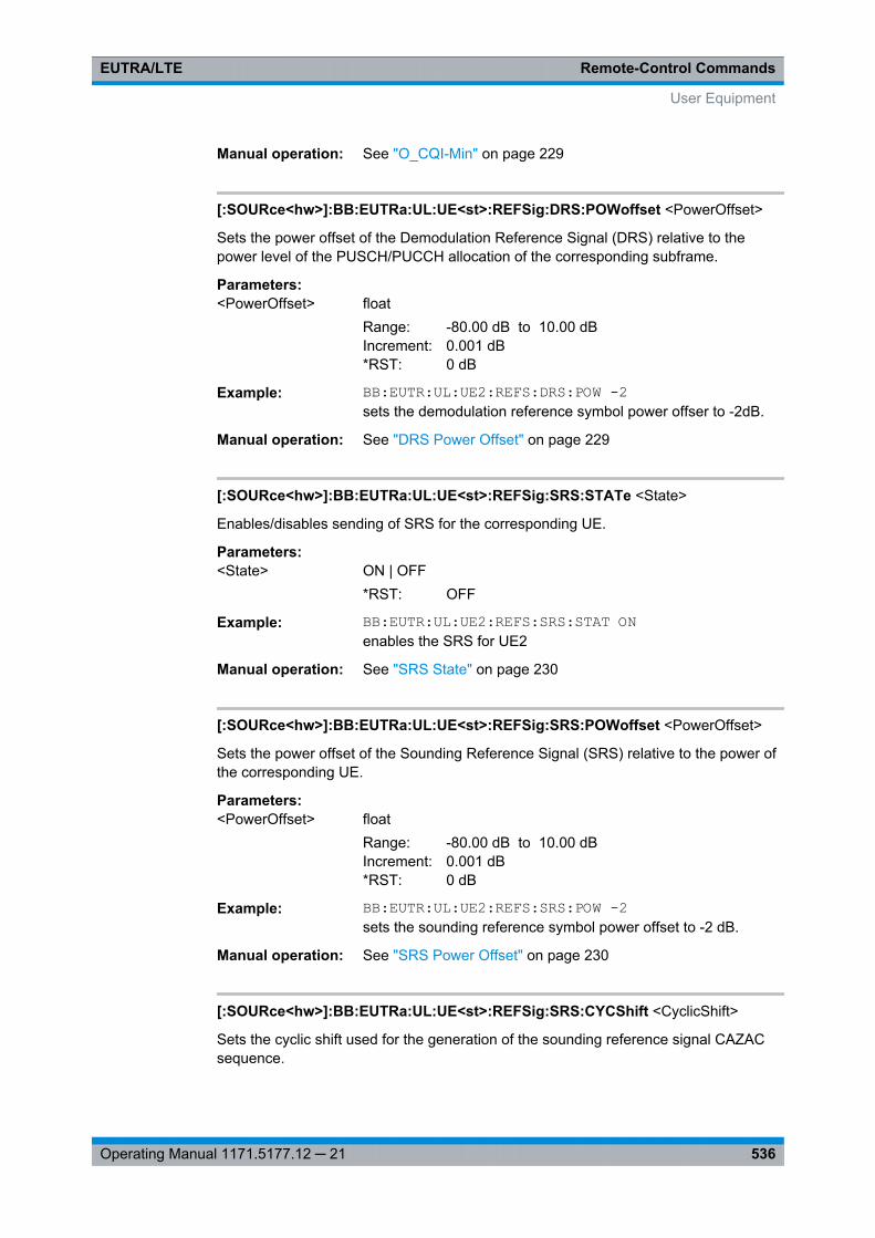
Remote-Control CommandsEUTRA/LTE
536Operating Manual 1171.5177.12 ─ 21
Manual operation: See "O_CQI-Min" on page 229
[:SOURce<hw>]:BB:EUTRa:UL:UE<st>:REFSig:DRS:POWoffset <PowerOffset>
Sets the power offset of the Demodulation Reference Signal (DRS) relative to thepower level of the PUSCH/PUCCH allocation of the corresponding subframe.
Parameters:<PowerOffset> float
Range: -80.00 dB to 10.00 dBIncrement: 0.001 dB*RST: 0 dB
Example: BB:EUTR:UL:UE2:REFS:DRS:POW -2sets the demodulation reference symbol power offser to -2dB.
Manual operation: See "DRS Power Offset" on page 229
[:SOURce<hw>]:BB:EUTRa:UL:UE<st>:REFSig:SRS:STATe <State>
Enables/disables sending of SRS for the corresponding UE.
Parameters:<State> ON | OFF
*RST: OFF
Example: BB:EUTR:UL:UE2:REFS:SRS:STAT ONenables the SRS for UE2
Manual operation: See "SRS State" on page 230
[:SOURce<hw>]:BB:EUTRa:UL:UE<st>:REFSig:SRS:POWoffset <PowerOffset>
Sets the power offset of the Sounding Reference Signal (SRS) relative to the power ofthe corresponding UE.
Parameters:<PowerOffset> float
Range: -80.00 dB to 10.00 dBIncrement: 0.001 dB*RST: 0 dB
Example: BB:EUTR:UL:UE2:REFS:SRS:POW -2sets the sounding reference symbol power offset to -2 dB.
Manual operation: See "SRS Power Offset" on page 230
[:SOURce<hw>]:BB:EUTRa:UL:UE<st>:REFSig:SRS:CYCShift <CyclicShift>
Sets the cyclic shift used for the generation of the sounding reference signal CAZACsequence.
User Equipment

Remote-Control CommandsEUTRA/LTE
537Operating Manual 1171.5177.12 ─ 21
Parameters:<CyclicShift> integer
Range: 0 to 7Increment: 1*RST: 0
Example: BB:EUTR:UL:UE2:REFS:SRS:CYCS 5sets the SRS cyclic shift for UE2
Manual operation: See "SRS Cyclic Shift n_CS" on page 230
[:SOURce<hw>]:BB:EUTRa:UL:UE<st>:REFSig:SRS:BHOP <BandwidthHopp>
Sets the UE specific parameter frequency hopping bandwidth bhop, as defined in the3GPP TS 36.211, chapter 5.5.3.2.
SRS frequency hopping is enabled, if bHOP<BSRS.
Parameters:<BandwidthHopp> integer
Range: 0 to 3Increment: 1*RST: 0
Example: BB:EUTR:UL:UE2:REFS:SRS:BHOP 2sets the SRS hopping bandwidth
Manual operation: See "Hopping Bandwidth b_hop" on page 236
[:SOURce<hw>]:BB:EUTRa:UL:UE<st>:REFSig:SRS:BSRS <Bsrs>
Sets the UE specific parameter SRS Bandwidth BSRS, as defined in the3GPP TS 36.211, chapter 5.5.3.2.
Parameters:<Bsrs> integer
Range: 0 to 3Increment: 1*RST: 0
Example: BB:EUTR:UL:UE2:REFS:SRS:BSRS 2sets the SRS bandwidth configuration
Manual operation: See "SRS Bandwidth B_SRS" on page 233
[:SOURce<hw>]:BB:EUTRa:UL:UE<st>:REFSig:SRS:ISRS <Isrs>
Sets the UE specific parameter SRS configuration index ISRS. Depending on theselected duplexing mode ([: SOURce<hw>]: BB:EUTRa: DUPLexing), this parameterdetermines the parameters SRS Periodicity TSRS and SRS Subframe Offset Toffset asdefined in the 3GPP TS 36.213, Table 8.2-1 (FDD) and 8.2-2 (TDD) respectively.
User Equipment
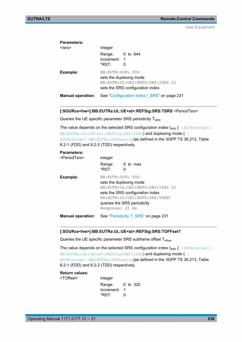
Remote-Control CommandsEUTRA/LTE
538Operating Manual 1171.5177.12 ─ 21
Parameters:<Isrs> integer
Range: 0 to 644Increment: 1*RST: 0
Example: BB:EUTR:DUPL FDDsets the duplexing modeBB:EUTR:UL:UE2:REFS:SRS:ISRS 22sets the SRS configuration index
Manual operation: See "Configuration Index I_SRS" on page 231
[:SOURce<hw>]:BB:EUTRa:UL:UE<st>:REFSig:SRS:TSRS <PeriodTsrs>
Queries the UE specific parameter SRS periodicity TSRS.
The value depends on the selected SRS configuration index ISRS ([:SOURce<hw>]: BB: EUTRa:UL:UE<st>: REFSig: SRS:ISRS ) and duplexing mode ([:SOURce<hw>]: BB: EUTRa:DUPLexing )as defined in the 3GPP TS 36.213, Table8.2-1 (FDD) and 8.2-2 (TDD) respectively.
Parameters:<PeriodTsrs> integer
Range: 0 to max*RST: 0
Example: BB:EUTR:DUPL FDDsets the duplexing modeBB:EUTR:UL:UE2:REFS:SRS:ISRS 22sets the SRS configuration indexBB:EUTR:UL:UE2:REFS:SRS:TSRS?queries the SRS periodicityResponse: 20 ms
Manual operation: See "Periodicity T_SRS" on page 231
[:SOURce<hw>]:BB:EUTRa:UL:UE<st>:REFSig:SRS:TOFFset?
Queries the UE specific parameter SRS subframe offset Toffset.
The value depends on the selected SRS configuration index ISRS ([:SOURce<hw>]: BB: EUTRa:UL: UE<st>:REFSig: SRS:ISRS ) and duplexing mode ([: SOURce<hw>]: BB:EUTRa: DUPLexing)as defined in the 3GPP TS 36.213, Table8.2-1 (FDD) and 8.2-2 (TDD) respectively.
Return values: <TOffset> integer
Range: 0 to 320Increment: 1*RST: 0
User Equipment
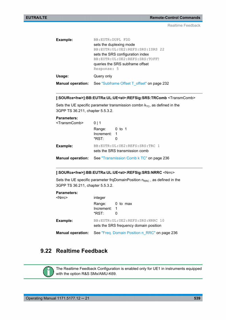
Remote-Control CommandsEUTRA/LTE
539Operating Manual 1171.5177.12 ─ 21
Example: BB:EUTR:DUPL FDDsets the duplexing modeBB:EUTR:UL:UE2:REFS:SRS:ISRS 22sets the SRS configuration indexBB:EUTR:UL:UE2:REFS:SRS:TOFF?queries the SRS subframe offsetResponse: 5
Usage: Query only
Manual operation: See "Subframe Offset T_offset" on page 232
[:SOURce<hw>]:BB:EUTRa:UL:UE<st>:REFSig:SRS:TRComb <TransmComb>
Sets the UE specific parameter transmission combn kTC, as defined in the3GPP TS 36.211, chapter 5.5.3.2.
Parameters:<TransmComb> 0 | 1
Range: 0 to 1Increment: 1*RST: 0
Example: BB:EUTR:UL:UE2:REFS:SRS:TRC 1sets the SRS transmission comb
Manual operation: See "Transmission Comb k TC" on page 236
[:SOURce<hw>]:BB:EUTRa:UL:UE<st>:REFSig:SRS:NRRC <Nrrc>
Sets the UE specific parameter frqDomainPosition nRRC , as defined in the3GPP TS 36.211, chapter 5.5.3.2.
Parameters:<Nrrc> integer
Range: 0 to maxIncrement: 1*RST: 0
Example: BB:EUTR:UL:UE2:REFS:SRS:NRRC 10sets the SRS frequency domain position
Manual operation: See "Freq. Domain Position n_RRC" on page 236
9.22 Realtime Feedback
The Realtime Feedback Configuration is enabled only for UE1 in instruments equippedwith the option R&S SMx/AMU-K69.
Realtime Feedback
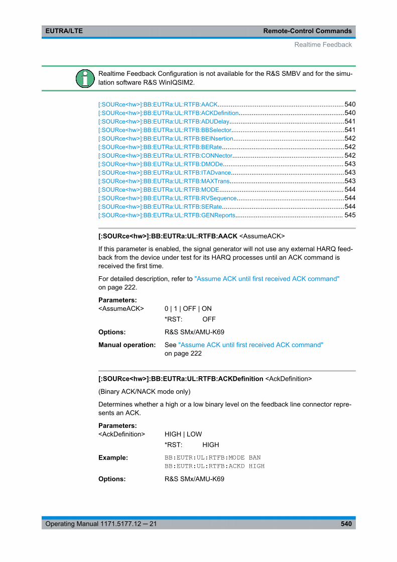
Remote-Control CommandsEUTRA/LTE
540Operating Manual 1171.5177.12 ─ 21
Realtime Feedback Configuration is not available for the R&S SMBV and for the simu-lation software R&S WinIQSIM2.
[:SOURce<hw>]:BB:EUTRa:UL:RTFB:AACK....................................................................540[:SOURce<hw>]:BB:EUTRa:UL:RTFB:ACKDefinition.........................................................540[:SOURce<hw>]:BB:EUTRa:UL:RTFB:ADUDelay..............................................................541[:SOURce<hw>]:BB:EUTRa:UL:RTFB:BBSelector.............................................................541[:SOURce<hw>]:BB:EUTRa:UL:RTFB:BEINsertion............................................................542[:SOURce<hw>]:BB:EUTRa:UL:RTFB:BERate..................................................................542[:SOURce<hw>]:BB:EUTRa:UL:RTFB:CONNector............................................................ 542[:SOURce<hw>]:BB:EUTRa:UL:RTFB:DMODe................................................................. 543[:SOURce<hw>]:BB:EUTRa:UL:RTFB:ITADvance.............................................................543[:SOURce<hw>]:BB:EUTRa:UL:RTFB:MAXTrans..............................................................543[:SOURce<hw>]:BB:EUTRa:UL:RTFB:MODE................................................................... 544[:SOURce<hw>]:BB:EUTRa:UL:RTFB:RVSequence..........................................................544[:SOURce<hw>]:BB:EUTRa:UL:RTFB:SERate..................................................................544[:SOURce<hw>]:BB:EUTRa:UL:RTFB:GENReports.......................................................... 545
[:SOURce<hw>]:BB:EUTRa:UL:RTFB:AACK <AssumeACK>
If this parameter is enabled, the signal generator will not use any external HARQ feed-back from the device under test for its HARQ processes until an ACK command isreceived the first time.
For detailed description, refer to "Assume ACK until first received ACK command"on page 222.
Parameters:<AssumeACK> 0 | 1 | OFF | ON
*RST: OFF
Options: R&S SMx/AMU-K69
Manual operation: See "Assume ACK until first received ACK command"on page 222
[:SOURce<hw>]:BB:EUTRa:UL:RTFB:ACKDefinition <AckDefinition>
(Binary ACK/NACK mode only)
Determines whether a high or a low binary level on the feedback line connector repre-sents an ACK.
Parameters:<AckDefinition> HIGH | LOW
*RST: HIGH
Example: BB:EUTR:UL:RTFB:MODE BANBB:EUTR:UL:RTFB:ACKD HIGH
Options: R&S SMx/AMU-K69
Realtime Feedback
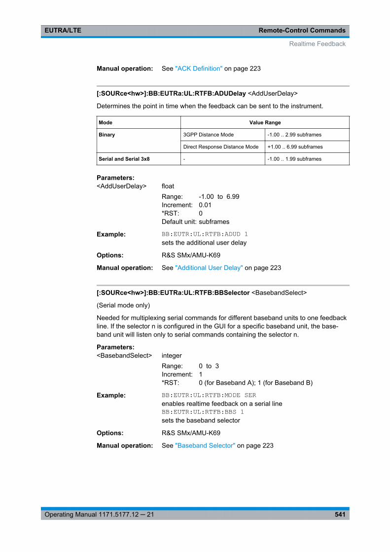
Remote-Control CommandsEUTRA/LTE
541Operating Manual 1171.5177.12 ─ 21
Manual operation: See "ACK Definition" on page 223
[:SOURce<hw>]:BB:EUTRa:UL:RTFB:ADUDelay <AddUserDelay>
Determines the point in time when the feedback can be sent to the instrument.
Mode Value Range
Binary 3GPP Distance Mode -1.00 .. 2.99 subframes
Direct Response Distance Mode +1.00 .. 6.99 subframes
Serial and Serial 3x8 - -1.00 .. 1.99 subframes
Parameters:<AddUserDelay> float
Range: -1.00 to 6.99Increment: 0.01*RST: 0Default unit: subframes
Example: BB:EUTR:UL:RTFB:ADUD 1sets the additional user delay
Options: R&S SMx/AMU-K69
Manual operation: See "Additional User Delay" on page 223
[:SOURce<hw>]:BB:EUTRa:UL:RTFB:BBSelector <BasebandSelect>
(Serial mode only)
Needed for multiplexing serial commands for different baseband units to one feedbackline. If the selector n is configured in the GUI for a specific baseband unit, the base-band unit will listen only to serial commands containing the selector n.
Parameters:<BasebandSelect> integer
Range: 0 to 3Increment: 1*RST: 0 (for Baseband A); 1 (for Baseband B)
Example: BB:EUTR:UL:RTFB:MODE SERenables realtime feedback on a serial lineBB:EUTR:UL:RTFB:BBS 1sets the baseband selector
Options: R&S SMx/AMU-K69
Manual operation: See "Baseband Selector" on page 223
Realtime Feedback
Remote-Control CommandsEUTRA/LTE
542Operating Manual 1171.5177.12 ─ 21
[:SOURce<hw>]:BB:EUTRa:UL:RTFB:BEINsertion <BlockErrInsert>
Enables/disables the statistical insertion of block errors into PUSCH packets.
The block error insertion can be enabled for a single HARQ process or for all pro-cesses.
In the single HARQ process case, the used process is always the one that corre-sponds to the first activated PUSCH.
Parameters:<BlockErrInsert> OFF | FPRocess | APRocesses
*RST: OFF
Example: BB:EUTR:UL:RTFB:BEIN FPRenables block error insertion for the first process
Options: R&S SMx/AMU-K69
Manual operation: See "Block Error Insertion" on page 224
[:SOURce<hw>]:BB:EUTRa:UL:RTFB:BERate <BlockErrRate>
Block error rate for the statistical insertion of block errors.
Parameters:<BlockErrRate> float
Range: 0.0001 to 1.0Increment: 0.0001*RST: 0.0001
Example: BB:EUTR:UL:RTFB:BER 0.5sets the block error rate
Options: R&S SMx/AMU-K69
Manual operation: See "Block Error Rate" on page 224
[:SOURce<hw>]:BB:EUTRa:UL:RTFB:CONNector <Connector>
Determines the feedback line connector (LEVATT or USER1).
Parameters:<Connector> LEVatt | USER1
*RST: USER1
Example: BB:EUTR:UL:RTFB:CONN USER1sets the connector
Options: R&S SMx/AMU-K69
Manual operation: See "Connector" on page 223
Realtime Feedback
Remote-Control CommandsEUTRA/LTE
543Operating Manual 1171.5177.12 ─ 21
[:SOURce<hw>]:BB:EUTRa:UL:RTFB:DMODe <DistanceMode>
Detemines how the number of the uplink subframe is calculated, in which the signaledfeedback has the desired effect.
Parameters:<DistanceMode> STD | DIRect
*RST: STD
Example: BB:EUTR:UL:RTFB:DMOD DIRsets direct distance mode
Options: R&S SMx/AMU-K69
Manual operation: See "Distance Mode" on page 223
[:SOURce<hw>]:BB:EUTRa:UL:RTFB:ITADvance <InitTimAdvance>
The initial timing advance of the uplink signal (at the output of the instrument's base-band unit) in units of 16 TS.
Parameters:<InitTimAdvance> integer
Range: 0 x 16 Ts to 1282 x 16 TsIncrement: 1 x 16 Ts*RST: 0 x 16 Ts
Example: BB:EUTR:UL:RTFB:ITAD 16sets the inital timing advance
Options: R&S SMx/AMU-K69
Manual operation: See "Realtime Feedback Mode" on page 221
[:SOURce<hw>]:BB:EUTRa:UL:RTFB:MAXTrans <MaxTransmission>
After this maximum number of transmissions (incl. first transmission), the first redun-dancy version of the redundancy version sequence is used even in case of NACK.
Parameters:<MaxTransmission> integer
Range: 1 to 20Increment: 1*RST: 4
Example: BB:EUTR:UL:RTFB:MAXT 5sets the maximum number of transmissions
Options: R&S SMx/AMU-K69
Manual operation: See "Max. Number of Transmissions" on page 222
Realtime Feedback
Remote-Control CommandsEUTRA/LTE
544Operating Manual 1171.5177.12 ─ 21
[:SOURce<hw>]:BB:EUTRa:UL:RTFB:MODE <Mode>
Enables realtime feedback and determines the mode (binary or serial).
Parameters:<Mode> OFF | BAN | SERial | S3X8
*RST: OFF
Example: BB:EUTR:UL:RTFB:MODE SERenables realtime feedback on a serial line
Options: R&S SMx/AMU-K69
[:SOURce<hw>]:BB:EUTRa:UL:RTFB:RVSequence <RedVersSequence>
Determines the sequence of redundancy versions for the individual HARQ processes.
Unless otherwise requested by serial feedback commands, the first value in thesequence of redundancy versions is used each time an ACK is received or for the veryfirst transmission of a process.
The sequence of redundancy versions is read out cyclically, i.e. whenever a NACK isreceived and a retransmission is requested, the next redundancy version in thesequence is used.
The first value in the sequence is used again even in case a NACK is received, if themaximum number of transmissions (BB:EUTR:UL:RTFB:MAXT) in a process wasreached.
Parameters:<RedVersSequence> string
Example: BB:EUTR:UL:RTFB:RVS '0,2,3,1'sets the redundancy version sequence
Options: R&S SMx/AMU-K69
Manual operation: See "Redundancy Version Sequence" on page 221
[:SOURce<hw>]:BB:EUTRa:UL:RTFB:SERate <SerialRate>
(Serial mode only)
Determines the bit rate of the serial transmission.
Parameters:<SerialRate> SR115_2K | SR1_92M | SR1_6M
*RST: SR115_2K
Example: BB:EUTR:UL:RTFB:MODE SERenables realtime feedback on a serial lineBB:EUTR:UL:RTFB:SER SR115_2Ksets the serial rate
Options: R&S SMx/AMU-K69
Realtime Feedback
Remote-Control CommandsEUTRA/LTE
545Operating Manual 1171.5177.12 ─ 21
Manual operation: See "Serial Rate" on page 223
[:SOURce<hw>]:BB:EUTRa:UL:RTFB:GENReports <GenDebugReports>
Triggers the instrument to create and store transmission and/or reception realtimefeedback debug reports.
Parameters:<GenDebugReports> 0 | 1 | OFF | ON
*RST: 0
Example: :SOURce1:BB:EUTRa:UL:RTFB:GENReports ONenables the generation of debug report files
Manual operation: See "Generate Debug Reports" on page 224
9.23 LTE Logfiles Generation
Logfile Generation requires an additional SW option and is enabled only for instru-ments equipped with R&S SMx/AMU-K81.
Example: Logfiles GenerationSOUR:BB:EUTR:LOGG:OUTP '<root>logfiles'SOUR:BB:EUTR:LOGG:LFP '201008Log'SOUR:BB:EUTR:LOGG:DL:EDL ONSOUR:BB:EUTR:LOGG:DL:PBCH ONSOUR:BB:EUTR:LOGG:DL:LOGP9 ONSOUR:BB:EUTR:LOGG:STAT ONSOUR:BB:EUTR:STAT ON
[:SOURce<hw>]:BB:EUTRa:LOGGen:STATe <LoggingState>
Enables/disables logfile generation.
Parameters:<LoggingState> 0 | 1 | OFF | ON
*RST: OFF
Example: example "Logfiles Generation" on page 545
Options: R&S SMx/AMU-K81
Manual operation: See "Logging State" on page 91
LTE Logfiles Generation
Remote-Control CommandsEUTRA/LTE
546Operating Manual 1171.5177.12 ─ 21
[:SOURce<hw>]:BB:EUTRa:LOGGen:OUTPut <OutputPath>
Selects the network directory the logged files are stored in.
Parameters:<OutputPath> string
*RST: C:\Documents and Settings\<user>\ApplicationData\Rohde-Schwarz\SMUFirmware\Log
Example: example "Logfiles Generation" on page 545
Options: R&S SMx/AMU-K81
Manual operation: See "Output Path" on page 91
[:SOURce<hw>]:BB:EUTRa:LOGGen:LFP <Preamble>
An optional preamble may be added to the file name. Refer to chapter 7.2.2.1, "FileNames", on page 82 for a description of the file naming convention used.
Parameters:<Preamble> string
*RST: K55Log
Example: example "Logfiles Generation" on page 545
Options: R&S SMx/AMU-K81
Manual operation: See "Logging Files Preamble" on page 92
[:SOURce<hw>]:BB:EUTRa:LOGGen:DL:EDLogging <ExtDciLog>[:SOURce<hw>]:BB:EUTRa:LOGGen:UL:EULogging <ExtUciLog>
Enables the generation of a logfile with extended information regarding the DCI/UCImapping.
Parameters:<ExtUciLog> 0 | 1 | OFF | ON
*RST: OFF
Example: example "Logfiles Generation" on page 545
Options: R&S SMx/AMU-K81
Manual operation: See "Extended DCI/UCI Logging" on page 92
[:SOURce<hw>]:BB:EUTRa:LOGGen:DL:EALL[:SOURce<hw>]:BB:EUTRa:LOGGen:UL:EALL[:SOURce<hw>]:BB:EUTRa:LOGGen:DL:DALL[:SOURce<hw>]:BB:EUTRa:LOGGen:UL:DALLEnables/disables all logging points.
Example: example "Logfiles Generation" on page 545
LTE Logfiles Generation
Remote-Control CommandsEUTRA/LTE
547Operating Manual 1171.5177.12 ─ 21
Options: R&S SMx/AMU-K81
Manual operation: See "Enable/Disable All" on page 92
[:SOURce<hw>]:BB:EUTRa:LOGGen:DL:LOGPoint<ch0> <LogPointState>[:SOURce<hw>]:BB:EUTRa:LOGGen:UL:LOGPoint<ch0> <LogPointState>
Enables/disables one particular logging point.
Refer to chapter 7.2.1, "Signal Processing Chains and Logging Points", on page 79 fordescription on the available logging points.
Parameters:<LogPointState> 0 | 1 | OFF | ON
*RST: OFF
Example: example "Logfiles Generation" on page 545
Options: R&S SMx/AMU-K81
Manual operation: See "Logging Point" on page 92
[:SOURce<hw>]:BB:EUTRa:LOGGen:DL:ENCC <EnccLogState>[:SOURce<hw>]:BB:EUTRa:LOGGen:DL:PBCH <PbchLogState>[:SOURce<hw>]:BB:EUTRa:LOGGen:DL:PDSCh <PdschLogState>[:SOURce<hw>]:BB:EUTRa:LOGGen:DL:PMCH <State>[:SOURce<hw>]:BB:EUTRa:LOGGen:UL:PUSCh <PuschLogState>
Enables the channel for that logfiles are generated.
Parameters:<PuschLogState> 0 | 1 | OFF | ON
*RST: ON
Example: example "Logfiles Generation" on page 545
Options: R&S SMx/AMU-K81
Manual operation: See "Physical Channels" on page 92
9.24 Test Case Wizard Remote-Control Commands
The "Test Case Wizard" is supported by R&S SMU, R&S SMATE, R&S SMJ and R&SSMBV.
The signal generator gives you the opportunity to generate predefined settings whichenable tests on base stations in conformance with the 3G standard EUTRA/LTE. Itoffers a selection of predefined settings according to Test Cases in TS 36.141. The
Test Case Wizard Remote-Control Commands
Remote-Control CommandsEUTRA/LTE
548Operating Manual 1171.5177.12 ─ 21
settings take effect only after execution of command [:SOURce<hw>]: BB:EUTRa: TCW: APPLysettings .
[:SOURce<hw>]:BB:EUTRa:TCW:APPLysettings..............................................................549[:SOURce<hw>]:BB:EUTRa:TCW:AWGN:PLEVel?........................................................... 550[:SOURce<hw>]:BB:EUTRa:TCW:FA:FRALlocation.......................................................... 550[:SOURce<hw>]:BB:EUTRa:TCW:FA:RBALlocation.......................................................... 550[:SOURce<hw>]:BB:EUTRa:TCW:GS:RELease................................................................ 550[:SOURce<hw>]:BB:EUTRa:TCW:GS:ANTSubset.............................................................550[:SOURce<hw>]:BB:EUTRa:TCW:GS:GENSignals............................................................550[:SOURce<hw>]:BB:EUTRa:TCW:GS:INSTsetup.............................................................. 551[:SOURce<hw>]:BB:EUTRa:TCW:GS:MODE....................................................................551[:SOURce<hw>]:BB:EUTRa:TCW:GS:MARKerconfig........................................................ 551[:SOURce<hw>]:BB:EUTRa:TCW:GS:BSCLass................................................................551[:SOURce<hw>]:BB:EUTRa:TCW:GS:RXANtennas...........................................................552[:SOURce<hw>]:BB:EUTRa:TCW:GS:TXANtennas...........................................................552[:SOURce<hw>]:BB:EUTRa:TCW:GS:SIGRout.................................................................552[:SOURce<hw>]:BB:EUTRa:TCW:GS:TRIGgerconfig........................................................ 552[:SOURce<hw>]:BB:EUTRa:TCW:IS:CHBW?................................................................... 553[:SOURce<hw>]:BB:EUTRa:TCW:IS:CLID........................................................................553[:SOURce<hw>]:BB:EUTRa:TCW:IS:DUPLex...................................................................553[:SOURce<hw>]:BB:EUTRa:TCW:IS:FRSHift....................................................................553[:SOURce<hw>]:BB:EUTRa:TCW:IS2:IFTYpe?.................................................................554[:SOURce<hw>]:BB:EUTRa:TCW:IS:IFTYpe.................................................................... 554[:SOURce<hw>]:BB:EUTRa:TCW:IS:NRBLock?............................................................... 554[:SOURce<hw>]:BB:EUTRa:TCW:IS:NTAOffset................................................................554[:SOURce<hw>]:BB:EUTRa:TCW:IS:OCEDge.................................................................. 554[:SOURce<hw>]:BB:EUTRa:TCW:IS:OVRB?....................................................................555[:SOURce<hw>]:BB:EUTRa:TCW:IS2:PLEVel?.................................................................555[:SOURce<hw>]:BB:EUTRa:TCW:IS3:PLEVel?.................................................................555[:SOURce<hw>]:BB:EUTRa:TCW:IS:PLEVel?.................................................................. 555[:SOURce<hw>]:BB:EUTRa:TCW:IS:RBCFrequency.........................................................555[:SOURce<hw>]:BB:EUTRa:TCW:IS2:RFFRequency?...................................................... 555[:SOURce<hw>]:BB:EUTRa:TCW:IS:RFFRequency.......................................................... 555[:SOURce<hw>]:BB:EUTRa:TCW:IS:TDDConfig...............................................................556[:SOURce<hw>]:BB:EUTRa:TCW:IS:TMODel?................................................................. 556[:SOURce<hw>]:BB:EUTRa:TCW:IS:TREQuire.................................................................556[:SOURce<hw>]:BB:EUTRa:TCW:IS:UEID....................................................................... 556[:SOURce<hw>]:BB:EUTRa:TCW:MUE:TSRS.................................................................. 557[:SOURce<hw>]:BB:EUTRa:TCW:SUE:TSRS...................................................................557[:SOURce<hw>]:BB:EUTRa:TCW:RTF:ACKDefinition........................................................557[:SOURce<hw>]:BB:EUTRa:TCW:RTF:AUSDelay.............................................................557[:SOURce<hw>]:BB:EUTRa:TCW:RTF:BBSMue...............................................................557[:SOURce<hw>]:BB:EUTRa:TCW:RTF:BBSSue............................................................... 557[:SOURce<hw>]:BB:EUTRa:TCW:RTF:BBSelector............................................................557[:SOURce<hw>]:BB:EUTRa:TCW:RTF:CONMue.............................................................. 558[:SOURce<hw>]:BB:EUTRa:TCW:RTF:CONSue...............................................................558[:SOURce<hw>]:BB:EUTRa:TCW:RTF:CONNector........................................................... 558[:SOURce<hw>]:BB:EUTRa:TCW:RTF:MODE.................................................................. 558[:SOURce<hw>]:BB:EUTRa:TCW:RTF:SERRate.............................................................. 558
Test Case Wizard Remote-Control Commands

Remote-Control CommandsEUTRA/LTE
549Operating Manual 1171.5177.12 ─ 21
[:SOURce<hw>]:BB:EUTRa:TCW:TC...............................................................................558[:SOURce<hw>]:BB:EUTRa:TCW:WS:ACPucch............................................................... 559[:SOURce<hw>]:BB:EUTRa:TCW:WS:ANBits...................................................................559[:SOURce<hw>]:BB:EUTRa:TCW:WS:ANPattern?............................................................ 559[:SOURce<hw>]:BB:EUTRa:TCW:WS:BFORmat.............................................................. 559[:SOURce<hw>]:BB:EUTRa:TCW:WS:CHBW...................................................................560[:SOURce<hw>]:BB:EUTRa:TCW:WS:CLID..................................................................... 560[:SOURce<hw>]:BB:EUTRa:TCW:WS:CYCPrefix..............................................................560[:SOURce<hw>]:BB:EUTRa:TCW:WS:CQIPattern:PORT<ch0>..........................................560[:SOURce<hw>]:BB:EUTRa:TCW:WS:DUPLex.................................................................561[:SOURce<hw>]:BB:EUTRa:TCW:WS:FMTHroughput....................................................... 561[:SOURce<hw>]:BB:EUTRa:TCW:WS:FRC...................................................................... 561[:SOURce<hw>]:BB:EUTRa:TCW:WS:FROFfset...............................................................561[:SOURce<hw>]:BB:EUTRa:TCW:WS:HSMode................................................................ 561[:SOURce<hw>]:BB:EUTRa:TCW:WS:NTAOffset..............................................................561[:SOURce<hw>]:BB:EUTRa:TCW:IS:ORTCover?..............................................................562[:SOURce<hw>]:BB:EUTRa:TCW:IS2:ORTCover?............................................................562[:SOURce<hw>]:BB:EUTRa:TCW:IS3:ORTCover?............................................................562[:SOURce<hw>]:BB:EUTRa:TCW:WS:ORTCover[:PORT<ch0>]?.......................................562[:SOURce<hw>]:BB:EUTRa:TCW:WS:ORTCover?............................................................562[:SOURce<hw>]:BB:EUTRa:TCW:WS:OUPLevel.............................................................. 562[:SOURce<hw>]:BB:EUTRa:TCW:MUE:OVRB..................................................................562[:SOURce<hw>]:BB:EUTRa:TCW:SUE:OVRB.................................................................. 562[:SOURce<hw>]:BB:EUTRa:TCW:WS:OVRB....................................................................562[:SOURce<hw>]:BB:EUTRa:TCW:WS:PLEVel?................................................................ 563[:SOURce<hw>]:BB:EUTRa:TCW:WS:PLPC?...................................................................563[:SOURce<hw>]:BB:EUTRa:TCW:WS:PLPS?...................................................................563[:SOURce<hw>]:BB:EUTRa:TCW:IS:PRCOndition?.......................................................... 563[:SOURce<hw>]:BB:EUTRa:TCW:IS2:PRCOndition?........................................................ 563[:SOURce<hw>]:BB:EUTRa:TCW:IS3:PRCOndition?........................................................ 563[:SOURce<hw>]:BB:EUTRa:TCW:WS:PROCondition........................................................ 563[:SOURce<hw>]:BB:EUTRa:TCW:WS:RFFRequency........................................................563[:SOURce<hw>]:BB:EUTRa:TCW:WS:SPSFrame.............................................................564[:SOURce<hw>]:BB:EUTRa:TCW:WS:TDDConfig.............................................................564[:SOURce<hw>]:BB:EUTRa:TCW:WS:TIOBase?.............................................................. 564[:SOURce<hw>]:BB:EUTRa:TCW:MUE:UEID................................................................... 564[:SOURce<hw>]:BB:EUTRa:TCW:SUE:UEID....................................................................564[:SOURce<hw>]:BB:EUTRa:TCW:WS:UEID..................................................................... 564
[:SOURce<hw>]:BB:EUTRa:TCW:APPLysettings
Activates the current settings of the test case wizard.
Note: The settings of the selected test case becomes active only after executing thiscommand.
Usage: Event
Manual operation: See "Apply Settings" on page 288
Test Case Wizard Remote-Control Commands
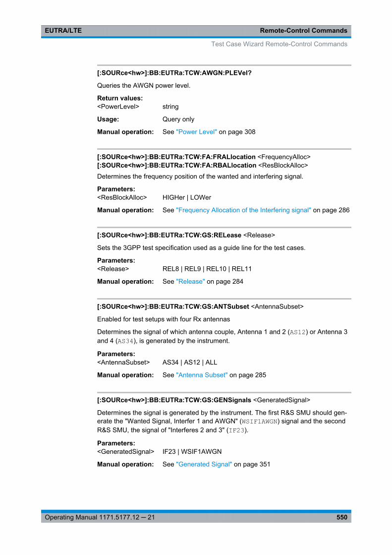
Remote-Control CommandsEUTRA/LTE
550Operating Manual 1171.5177.12 ─ 21
[:SOURce<hw>]:BB:EUTRa:TCW:AWGN:PLEVel?
Queries the AWGN power level.
Return values: <PowerLevel> string
Usage: Query only
Manual operation: See "Power Level" on page 308
[:SOURce<hw>]:BB:EUTRa:TCW:FA:FRALlocation <FrequencyAlloc>[:SOURce<hw>]:BB:EUTRa:TCW:FA:RBALlocation <ResBlockAlloc>
Determines the frequency position of the wanted and interfering signal.
Parameters:<ResBlockAlloc> HIGHer | LOWer
Manual operation: See "Frequency Allocation of the Interfering signal" on page 286
[:SOURce<hw>]:BB:EUTRa:TCW:GS:RELease <Release>
Sets the 3GPP test specification used as a guide line for the test cases.
Parameters:<Release> REL8 | REL9 | REL10 | REL11
Manual operation: See "Release" on page 284
[:SOURce<hw>]:BB:EUTRa:TCW:GS:ANTSubset <AntennaSubset>
Enabled for test setups with four Rx antennas
Determines the signal of which antenna couple, Antenna 1 and 2 (AS12) or Antenna 3and 4 (AS34), is generated by the instrument.
Parameters:<AntennaSubset> AS34 | AS12 | ALL
Manual operation: See "Antenna Subset" on page 285
[:SOURce<hw>]:BB:EUTRa:TCW:GS:GENSignals <GeneratedSignal>
Determines the signal is generated by the instrument. The first R&S SMU should gen-erate the "Wanted Signal, Interfer 1 and AWGN" (WSIF1AWGN) signal and the secondR&S SMU, the signal of "Interferes 2 and 3" (IF23).
Parameters:<GeneratedSignal> IF23 | WSIF1AWGN
Manual operation: See "Generated Signal" on page 351
Test Case Wizard Remote-Control Commands
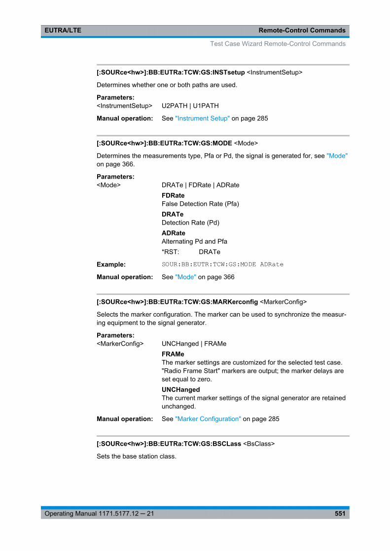
Remote-Control CommandsEUTRA/LTE
551Operating Manual 1171.5177.12 ─ 21
[:SOURce<hw>]:BB:EUTRa:TCW:GS:INSTsetup <InstrumentSetup>
Determines whether one or both paths are used.
Parameters:<InstrumentSetup> U2PATH | U1PATH
Manual operation: See "Instrument Setup" on page 285
[:SOURce<hw>]:BB:EUTRa:TCW:GS:MODE <Mode>
Determines the measurements type, Pfa or Pd, the signal is generated for, see "Mode"on page 366.
Parameters:<Mode> DRATe | FDRate | ADRate
FDRateFalse Detection Rate (Pfa)DRATeDetection Rate (Pd)ADRateAlternating Pd and Pfa*RST: DRATe
Example: SOUR:BB:EUTR:TCW:GS:MODE ADRateManual operation: See "Mode" on page 366
[:SOURce<hw>]:BB:EUTRa:TCW:GS:MARKerconfig <MarkerConfig>
Selects the marker configuration. The marker can be used to synchronize the measur-ing equipment to the signal generator.
Parameters:<MarkerConfig> UNCHanged | FRAMe
FRAMeThe marker settings are customized for the selected test case."Radio Frame Start" markers are output; the marker delays areset equal to zero.UNCHangedThe current marker settings of the signal generator are retainedunchanged.
Manual operation: See "Marker Configuration" on page 285
[:SOURce<hw>]:BB:EUTRa:TCW:GS:BSCLass <BsClass>
Sets the base station class.
Test Case Wizard Remote-Control Commands
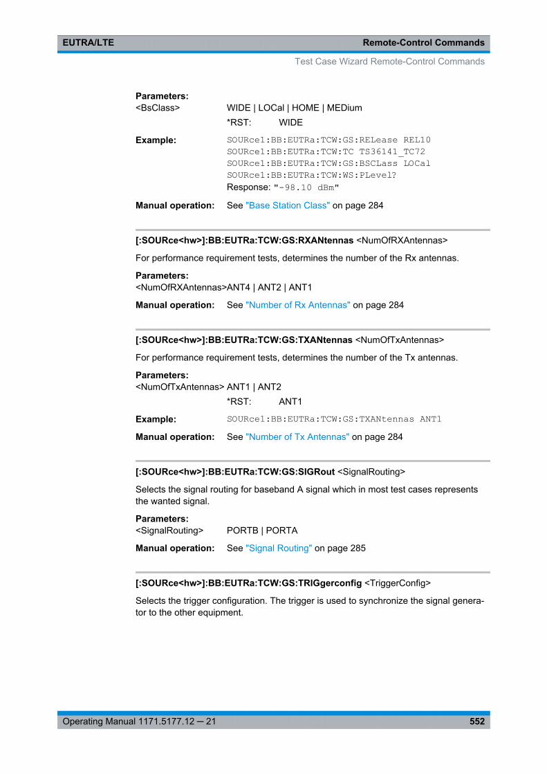
Remote-Control CommandsEUTRA/LTE
552Operating Manual 1171.5177.12 ─ 21
Parameters:<BsClass> WIDE | LOCal | HOME | MEDium
*RST: WIDE
Example: SOURce1:BB:EUTRa:TCW:GS:RELease REL10SOURce1:BB:EUTRa:TCW:TC TS36141_TC72SOURce1:BB:EUTRa:TCW:GS:BSCLass LOCalSOURce1:BB:EUTRa:TCW:WS:PLevel?Response: "-98.10 dBm"
Manual operation: See "Base Station Class" on page 284
[:SOURce<hw>]:BB:EUTRa:TCW:GS:RXANtennas <NumOfRXAntennas>
For performance requirement tests, determines the number of the Rx antennas.
Parameters:<NumOfRXAntennas>ANT4 | ANT2 | ANT1
Manual operation: See "Number of Rx Antennas" on page 284
[:SOURce<hw>]:BB:EUTRa:TCW:GS:TXANtennas <NumOfTxAntennas>
For performance requirement tests, determines the number of the Tx antennas.
Parameters:<NumOfTxAntennas> ANT1 | ANT2
*RST: ANT1
Example: SOURce1:BB:EUTRa:TCW:GS:TXANtennas ANT1Manual operation: See "Number of Tx Antennas" on page 284
[:SOURce<hw>]:BB:EUTRa:TCW:GS:SIGRout <SignalRouting>
Selects the signal routing for baseband A signal which in most test cases representsthe wanted signal.
Parameters:<SignalRouting> PORTB | PORTA
Manual operation: See "Signal Routing" on page 285
[:SOURce<hw>]:BB:EUTRa:TCW:GS:TRIGgerconfig <TriggerConfig>
Selects the trigger configuration. The trigger is used to synchronize the signal genera-tor to the other equipment.
Test Case Wizard Remote-Control Commands
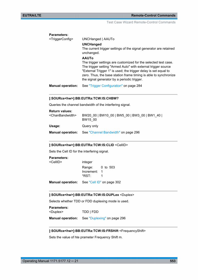
Remote-Control CommandsEUTRA/LTE
553Operating Manual 1171.5177.12 ─ 21
Parameters:<TriggerConfig> UNCHanged | AAUTo
UNCHangedThe current trigger settings of the signal generator are retainedunchanged.AAUToThe trigger settings are customized for the selected test case.The trigger setting "Armed Auto" with external trigger source"External Trigger 1" is used; the trigger delay is set equal tozero. Thus, the base station frame timing is able to synchronizethe signal generator by a periodic trigger.
Manual operation: See "Trigger Configuration" on page 284
[:SOURce<hw>]:BB:EUTRa:TCW:IS:CHBW?
Queries the channel bandwidth of the interfering signal.
Return values: <ChanBandwidth> BW20_00 | BW10_00 | BW5_00 | BW3_00 | BW1_40 |
BW15_00
Usage: Query only
Manual operation: See "Channel Bandwidth" on page 296
[:SOURce<hw>]:BB:EUTRa:TCW:IS:CLID <CellID>
Sets the Cell ID for the interfering signal.
Parameters:<CellID> integer
Range: 0 to 503Increment: 1*RST: 1
Manual operation: See "Cell ID" on page 302
[:SOURce<hw>]:BB:EUTRa:TCW:IS:DUPLex <Duplex>
Selects whether TDD or FDD duplexing mode is used.
Parameters:<Duplex> TDD | FDD
Manual operation: See "Duplexing" on page 296
[:SOURce<hw>]:BB:EUTRa:TCW:IS:FRSHift <FrequencyShift>
Sets the value of hte prameter Frequency Shift m.
Test Case Wizard Remote-Control Commands
Remote-Control CommandsEUTRA/LTE
554Operating Manual 1171.5177.12 ─ 21
Parameters:<FrequencyShift> FS24 | FS19 | FS14 | FS13 | FS10 | FS9 | FS7 | FS5 | FS4 |
FS3 | FS2 | FS1 | FS0
Manual operation: See "Frequency Shift m" on page 302
[:SOURce<hw>]:BB:EUTRa:TCW:IS2:IFTYpe?[:SOURce<hw>]:BB:EUTRa:TCW:IS:IFTYpe <InterfererType>
Selects the type of the interfering signal:● For Blocking tests, the interfering signal can be an in-band EUTRA/LTE signal
(EUTra) or out-of-band CW signal (CW).
● For Receiver Intermodulation tests, the first interfering signal can be anEUTRA/LTE signal (EUTra) or narrow-band EUTRA signal (NEUTra).The second interfering signal is always a CW signal (CW).
Parameters:<InterfererType> NEUTra | EUTra | CW
Manual operation: See "Interferer Type" on page 300
[:SOURce<hw>]:BB:EUTRa:TCW:IS:NRBLock?
Queries the number of RBs used by the LTE interfering signal.
Return values: <NumResBlock> integer
Range: 3 to 25Increment: 1*RST: 3
Usage: Query only
Manual operation: See "Number of Resource Blocks" on page 302
[:SOURce<hw>]:BB:EUTRa:TCW:IS:NTAOffset <SigAdvNTAoffset>
Sets the parameter NTAoffset.
Parameters:<SigAdvNTAoffset> NTA624 | NTA0
Manual operation: See "Signal Advance N_TA_offset" on page 301
[:SOURce<hw>]:BB:EUTRa:TCW:IS:OCEDge <OffsChannelEdge>
Defines the offset of the interfering signal center frequency relative to edge of the wan-ted channel bandwidth.
Test Case Wizard Remote-Control Commands
Remote-Control CommandsEUTRA/LTE
555Operating Manual 1171.5177.12 ─ 21
Parameters:<OffsChannelEdge> OCE12_5 | OCE7_5 | OCE2_5
*RST: OCE2_5
Manual operation: See "Offset to Channel Edge" on page 295
[:SOURce<hw>]:BB:EUTRa:TCW:IS:OVRB?
Sets the offset VRB.
Return values: <OffsetVRB> integer
Range: 0 to 75Increment: 1*RST: 0
Usage: Query only
Manual operation: See "Offset VRB" on page 302
[:SOURce<hw>]:BB:EUTRa:TCW:IS2:PLEVel?[:SOURce<hw>]:BB:EUTRa:TCW:IS3:PLEVel?[:SOURce<hw>]:BB:EUTRa:TCW:IS:PLEVel?Queries the power level of the interfering signal.
Return values: <PowerLevel> string
Usage: Query only
Manual operation: See "Power Level" on page 297
[:SOURce<hw>]:BB:EUTRa:TCW:IS:RBCFrequency <RBlockCentFreq>
Queries the center frequency of the single resource block interfering signal.
Parameters:<RBlockCentFreq> float
Range: 100e+03 to 6e+09Increment: 1*RST: 1.95e+09
Manual operation: See "Interfering RB Center Frequency" on page 303
[:SOURce<hw>]:BB:EUTRa:TCW:IS2:RFFRequency?[:SOURce<hw>]:BB:EUTRa:TCW:IS:RFFRequency <RfFrequency>
Queries the center frequency of the interfering signal.
Test Case Wizard Remote-Control Commands
Remote-Control CommandsEUTRA/LTE
556Operating Manual 1171.5177.12 ─ 21
Parameters:<RfFrequency> float
Range: 100e+03 to 6e+09Increment: 1*RST: 1.95e+09
Manual operation: See "FR Frequency" on page 295
[:SOURce<hw>]:BB:EUTRa:TCW:IS:TDDConfig <TddConfig>
For TDD mode, selects the UL/DL Configuration number.
Parameters:<TddConfig> integer
Range: 0 to 6Increment: 1*RST: 0
Manual operation: See "TDD UL/DL Configuration" on page 301
[:SOURce<hw>]:BB:EUTRa:TCW:IS:TMODel?
Queries the test model. The interfering signal is generated according to E-TM1.1 testmodel.
Return values: <TestModel> TM1_1
Usage: Query only
Manual operation: See "Test Model" on page 296
[:SOURce<hw>]:BB:EUTRa:TCW:IS:TREQuire <TestRequire>
Selects whether the standard out-of-band blocking requirements test is performed(BLPE) or the optional blocking scenario, when the BS is co-located with another BS ina different operating band (COBS).
Parameters:<TestRequire> COBS | BLPE
Manual operation: See "Test Requirement" on page 320
[:SOURce<hw>]:BB:EUTRa:TCW:IS:UEID <UE_ID_nRNTI>
Sets the UE ID/n_RNTI for the interfering signal.
Parameters:<UE_ID_nRNTI> integer
Range: 0 to 65535Increment: 1*RST: 1
Test Case Wizard Remote-Control Commands
Remote-Control CommandsEUTRA/LTE
557Operating Manual 1171.5177.12 ─ 21
Manual operation: See "UE ID/n_RNTI" on page 302
[:SOURce<hw>]:BB:EUTRa:TCW:MUE:TSRS <TransmitSRS>[:SOURce<hw>]:BB:EUTRa:TCW:SUE:TSRS <TransmitSRS>
Enables/disables the transmission of the SRS.
The SRS transmission is optional for this test case.
Parameters:<TransmitSRS> 0 | 1 | OFF | ON
Manual operation: See "Transmit SRS" on page 335
[:SOURce<hw>]:BB:EUTRa:TCW:RTF:ACKDefinition <AckDefinition>
Determines whether a high or a low binary level on the feedback line connector repre-sents an ACK.
Parameters:<AckDefinition> LOW | HIGH
Manual operation: See "ACK Definition" on page 328
[:SOURce<hw>]:BB:EUTRa:TCW:RTF:AUSDelay <AddUserDelay>
Determines the point in time when the feedback can be sent to the instrument.
Parameters:<AddUserDelay> float
Range: -1 to +2.99Increment: 0.01*RST: 0
Manual operation: See "Additional User Delay" on page 327
[:SOURce<hw>]:BB:EUTRa:TCW:RTF:BBSMue <BBSelectMovUE>[:SOURce<hw>]:BB:EUTRa:TCW:RTF:BBSSue <BBSelectStatUE>[:SOURce<hw>]:BB:EUTRa:TCW:RTF:BBSelector <BBSelector>
This parameter is required for multiplexing serial commands for different basebandunits to one feedback line. If the selector n is configured in the GUI for a specific base-band unit, the baseband unit will listen only to serial commands containing the selectorn.
Parameters:<BBSelector> integer
Range: 0 to 3Increment: 1*RST: 0
Manual operation: See "Baseband Selector" on page 327
Test Case Wizard Remote-Control Commands
Remote-Control CommandsEUTRA/LTE
558Operating Manual 1171.5177.12 ─ 21
[:SOURce<hw>]:BB:EUTRa:TCW:RTF:CONMue <ConnectorMovUE>[:SOURce<hw>]:BB:EUTRa:TCW:RTF:CONSue <ConnectorStatUE>[:SOURce<hw>]:BB:EUTRa:TCW:RTF:CONNector <Connector>
Determines the feedback line connector (LEVATT or USER1).
Parameters:<Connector> LEVatt | USER1 | NOFB
Manual operation: See "Connector" on page 327
[:SOURce<hw>]:BB:EUTRa:TCW:RTF:MODE <Mode>
Determines the feedback mode.
Parameters:<Mode> SER3X8 | SER | BIN
BINBinary ACK/NACKThe ACK/NACK feedback is implemented as low/high voltagelevel on the feedback line connector.SERSerialACK/NACK Feedback and Timing Adjustments Feedback areimplemented by means of a serial protocol.SER3X8Serial 3x8ACK/NACK Feedback and Timing Adjustments Feedback areimplemented by means of a serial commands, consisting ofthree serial packets.
Manual operation: See "Realtime Feedback Mode" on page 327
[:SOURce<hw>]:BB:EUTRa:TCW:RTF:SERRate <SerialRate>
Sets the bit rate of the serial transmission. Possible rates are 115.2 kbps, 1.6 Mbpsand 1.92 Mbps.
Parameters:<SerialRate> SR1_92M | SR1_6M | SR115_2K
Manual operation: See "Serial Rate" on page 328
[:SOURce<hw>]:BB:EUTRa:TCW:TC <TestCase>
Selects the test case.
Test Case Wizard Remote-Control Commands
Remote-Control CommandsEUTRA/LTE
559Operating Manual 1171.5177.12 ─ 21
Parameters:<TestCase> TS36141_TC67 | TS36141_TC72 | TS36141_TC73 |
TS36141_TC74 | TS36141_TC75A | TS36141_TC75B |TS36141_TC76 | TS36141_TC78 | TS36141_TC821 |TS36141_TC822 | TS36141_TC823 | TS36141_TC824 |TS36141_TC831 | TS36141_TC832 | TS36141_TC833 |TS36141_TC841 | TS36141_TC839 | TS36141_TC834 |TS36141_TC835 | TS36141_TC836
Manual operation: See "Test Case" on page 284
[:SOURce<hw>]:BB:EUTRa:TCW:WS:ACPucch <AddConfigPUCCH>
Enables the optional transmission of PUCCH format 2.
Parameters:<AddConfigPUCCH> 0 | 1 | OFF | ON
Manual operation: See "Additionally Configure PUCCH" on page 342
[:SOURce<hw>]:BB:EUTRa:TCW:WS:ANBits <AckNackBits>
In performace requirement test cases, sets the number of encoded ACK/NACK bits persubframe.
Parameters:<AckNackBits> ANB4 | ANB16
Example: SOURce1:BB:EUTRa:TCW:TC TS36141_TC836SOURce1:BB:EUTRa:TCW:WS:ANBits?Response: ANB16
Manual operation: See "Number of ACK/NACK bits" on page 357
[:SOURce<hw>]:BB:EUTRa:TCW:WS:ANPattern?
In performace requirement test cases, queries the ACK/NACK + SR pattern bits.
Return values: <AckNackPattern> integer
Example: SOURce1:BB:EUTRa:TCW:TC TS36141_TC836SOURce1:BB:EUTRa:TCW:WS:ANPattern?Response: "00000000000000000"
Usage: Query only
Manual operation: See "ACK/NACK + SR Pattern" on page 358
[:SOURce<hw>]:BB:EUTRa:TCW:WS:BFORmat <BurstFormat>
Sets the burst format.
Test Case Wizard Remote-Control Commands
Remote-Control CommandsEUTRA/LTE
560Operating Manual 1171.5177.12 ─ 21
Parameters:<BurstFormat> BF4 | BF3 | BF2 | BF1 | BF0
Manual operation: See "Burst Format" on page 366
[:SOURce<hw>]:BB:EUTRa:TCW:WS:CHBW <ChanBandwidth>
Selects the channel bandwidth.
Parameters:<ChanBandwidth> BW20_00 | BW10_00 | BW5_00 | BW3_00 | BW1_40 |
BW15_00
Manual operation: See "Channel Bandwidth" on page 287
[:SOURce<hw>]:BB:EUTRa:TCW:WS:CLID <CellId>
Sets the Cell ID.
Parameters:<CellId> integer
Range: 0 to 503Increment: 1*RST: 150
Manual operation: See "Cell ID" on page 287
[:SOURce<hw>]:BB:EUTRa:TCW:WS:CYCPrefix <CyclicPrefix>
Selects normal or extended cyclic prefix.
Parameters:<CyclicPrefix> EXTended | NORMal
Manual operation: See "Cyclic Prefix" on page 287
[:SOURce<hw>]:BB:EUTRa:TCW:WS:CQIPattern:PORT<ch0> <CqiPattern>
In performance test cases, sets the CQI Pattern.
Parameters:<CqiPattern> integer
Example: SOURce1:BB:EUTRa:TCW:TC TS36141_TC839SOURce1:BB:EUTRa:TCW:GS:TXANtennas ANT2SOURce1:BB:EUTRa:TCW:WS:CQIPattern:PORT0 #H5,4SOURce1:BB:EUTRa:TCW:WS:CQIPattern:PORT1 #H5,4
Manual operation: See "CQI Pattern Port 0/1 (bin)" on page 363
Test Case Wizard Remote-Control Commands
Remote-Control CommandsEUTRA/LTE
561Operating Manual 1171.5177.12 ─ 21
[:SOURce<hw>]:BB:EUTRa:TCW:WS:DUPLex <Duplex>
Selects whether TDD or FDD duplexing mode is used.
Parameters:<Duplex> TDD | FDD
Manual operation: See "Duplexing" on page 287
[:SOURce<hw>]:BB:EUTRa:TCW:WS:FMTHroughput <FractMaxThrough>
Selects the fraction of maximum throughput.
Parameters:<FractMaxThrough> FMT70 | FMT30
Manual operation: See "Fraction of Max. Throughput" on page 332
[:SOURce<hw>]:BB:EUTRa:TCW:WS:FRC <FRC>
Queries the fixed reference channel used.
Parameters:<FRC> A11 | A12 | A13 | A14 | A15 | A21 | A22 | A23 | A31 | A32 | A33 |
A34 | A35 | A36 | A37 | A41 | A42 | A43 | A44 | A45 | A46 | A47 |A48 | A51 | A52 | A53 | A54 | A55 | A56 | A57 | A71 | A72 | A73 |A74 | A75 | A76 | A81 | A82 | A83 | A84 | A85 | A86 | UE11 |UE12 | UE21 | UE22 | UE3
Manual operation: See "FRC" on page 288
[:SOURce<hw>]:BB:EUTRa:TCW:WS:FROFfset <FreqOffset>
Sets the frequency offset.
Parameters:<FreqOffset> FO_1340 | FO_625 | FO_270 | FO_0
Manual operation: See "Frequency Offset" on page 366
[:SOURce<hw>]:BB:EUTRa:TCW:WS:HSMode <HighSpeedMode>
Enables/disables high speed mode.
Parameters:<HighSpeedMode> 0 | 1 | OFF | ON
Manual operation: See "High Speed Mode" on page 366
[:SOURce<hw>]:BB:EUTRa:TCW:WS:NTAOffset <SigAdvNTAoffset>
Sets the parameter NTAoffset.
Test Case Wizard Remote-Control Commands
Remote-Control CommandsEUTRA/LTE
562Operating Manual 1171.5177.12 ─ 21
Parameters:<SigAdvNTAoffset> NTA624 | NTA0
Manual operation: See "Signal Advance N_TA_offset" on page 287
[:SOURce<hw>]:BB:EUTRa:TCW:IS:ORTCover?[:SOURce<hw>]:BB:EUTRa:TCW:IS2:ORTCover?[:SOURce<hw>]:BB:EUTRa:TCW:IS3:ORTCover?[:SOURce<hw>]:BB:EUTRa:TCW:WS:ORTCover[:PORT<ch0>]?[:SOURce<hw>]:BB:EUTRa:TCW:WS:ORTCover?Queries the used resource index n_PUCCH.
Return values: <OrthoCover> integer
Range: 2 to 2Increment: 1*RST: 2
Usage: Query only
Manual operation: See "Orthogonal Cover (Res. Index n_PUCCH) / OrthogonalCover (Res. Index n_PUCCH) Port 0/1" on page 351
[:SOURce<hw>]:BB:EUTRa:TCW:WS:OUPLevel <OutPowerLevel>
The settings of the selected test case becomes active only after selecting "Apply Set-tings".
Parameters:<OutPowerLevel> float
Range: -115 to 0Increment: 0.01*RST: -30
Manual operation: See "Output Power Level" on page 295
[:SOURce<hw>]:BB:EUTRa:TCW:MUE:OVRB <OffsetVRB>[:SOURce<hw>]:BB:EUTRa:TCW:SUE:OVRB <OffsetVRB>[:SOURce<hw>]:BB:EUTRa:TCW:WS:OVRB <OffsetVRB>
Sets the number of RB the allocated RB(s) are shifted with.
Parameters:<OffsetVRB> integer
Range: 0 to 75Increment: 1*RST: 0
Manual operation: See "Offset VRB" on page 288
Test Case Wizard Remote-Control Commands
Remote-Control CommandsEUTRA/LTE
563Operating Manual 1171.5177.12 ─ 21
[:SOURce<hw>]:BB:EUTRa:TCW:WS:PLEVel?
Queries the Power Level.
Return values: <PowerLevel> string
Usage: Query only
Manual operation: See "Power Level" on page 288
[:SOURce<hw>]:BB:EUTRa:TCW:WS:PLPC?
Queries the resulting PUCCH power level by activated optional transmission ofPUCCH format 2.
Return values: <PowerLevelPUCCH>string
Usage: Query only
Manual operation: See "PUCCH Power Level" on page 342
[:SOURce<hw>]:BB:EUTRa:TCW:WS:PLPS?
Queries the resulting PUSCH power level.
Return values: <PowerLevelPUSCH>string
Usage: Query only
Manual operation: See "Power Level (PUSCH)" on page 342
[:SOURce<hw>]:BB:EUTRa:TCW:IS:PRCOndition?[:SOURce<hw>]:BB:EUTRa:TCW:IS2:PRCOndition?[:SOURce<hw>]:BB:EUTRa:TCW:IS3:PRCOndition?[:SOURce<hw>]:BB:EUTRa:TCW:WS:PROCondition <PropagationCond>
Selects a predefined multipath fading propagation conditions. The settings of the fad-ing simulator are adjusted according to the corresponding channel model as defined in3GPP TS 36.141, Annex B.
Parameters:<PropagationCond> AWGNonly | HST3 | HST1 | PDMov | ETU200Mov | ETU300 |
EVA70 | EVA5 | EPA5 | ETU70
Manual operation: See "Propagation Conditions" on page 328
[:SOURce<hw>]:BB:EUTRa:TCW:WS:RFFRequency <RfFrequency>
Sets the RF frequency of the wanted signal.
Test Case Wizard Remote-Control Commands
Remote-Control CommandsEUTRA/LTE
564Operating Manual 1171.5177.12 ─ 21
Parameters:<RfFrequency> float
Range: 100e+03 to 6e+09Increment: 1*RST: 1.95e+09
Manual operation: See "RF Frequency" on page 287
[:SOURce<hw>]:BB:EUTRa:TCW:WS:SPSFrame <SpecSubframe>
In TDD duplexing mode, sets the Special Subframe Configuration number.
Parameters:<SpecSubframe> integer
Range: 0 to 8Increment: 1*RST: 0
Manual operation: See "Configuration of Special Subframe" on page 366
[:SOURce<hw>]:BB:EUTRa:TCW:WS:TDDConfig <TddConfig>
For TDD mode, selects the UL/DL Configuration number.
Parameters:<TddConfig> integer
Range: 0 to 6Increment: 1*RST: 0
Manual operation: See "TDD UL/DL Configuration" on page 287
[:SOURce<hw>]:BB:EUTRa:TCW:WS:TIOBase?
Queries the timing offset base value.
Return values: <TimingOffsBase> float
Range: 0 to 500Increment: 0.01*RST: 0
Usage: Query only
Manual operation: See "Timing Offset Base Value" on page 367
[:SOURce<hw>]:BB:EUTRa:TCW:MUE:UEID <UE_ID_nRNTI>[:SOURce<hw>]:BB:EUTRa:TCW:SUE:UEID <UE_ID_nRNTI>[:SOURce<hw>]:BB:EUTRa:TCW:WS:UEID <UE_ID_nRNTI>
Sets the UE ID/n_RNTI.
Test Case Wizard Remote-Control Commands
Remote-Control CommandsEUTRA/LTE
565Operating Manual 1171.5177.12 ─ 21
Parameters:<UE_ID_nRNTI> integer
Range: 0 to 65535Increment: 1*RST: 1
Manual operation: See "UE ID/n_RNTI" on page 287
Test Case Wizard Remote-Control Commands

ReferencesEUTRA/LTE
566Operating Manual 1171.5177.12 ─ 21
A References● [1] 3GPP TR 25.913 "Requirements for Evolved UTRA (E-UTRA) and Evolved
UTRAN (E-UTRAN)"● [2] 3GPP TR 25.892 "Feasibility study for Orthogonal Frequency Division Multiplex-
ing (OFDM) for UTRAN enhancement"● [3] 3GPP TS 36.211 "Evolved Universal Terrestrial Radio Access (E-UTRA); Physi-
cal Channels and Modulation"● [4] 3GPP TS 36.212 "Evolved Universal Terrestrial Radio Access (E-UTRA); Multi-
plexing and channel coding"● [5] 3GPP TS 36.213 "Evolved Universal Terrestrial Radio Access (E-UTRA); Physi-
cal layer procedures"● [6] 3GPP TS 36.141 "Evolved Universal Terrestrial Radio Access (E-UTRA); Base
Station (BS) conformance testing"● [7] 3GPP TS 36.214 "Evolved Universal Terrestrial Radio Access (E-UTRA); Physi-
cal layer; Measurements"● [8] 3GPP TS 36.101 "Evolved Universal Terrestrial Radio Access (E-UTRA); User
Equipment (UE) radio transmission and reception"● [9] 3GPP TS 36.104 "Evolved Universal Terrestrial Radio Access (E-UTRA); Base
Station (BS) radio transmission and reception"● [10] 3GPP TS 36.113 "Evolved Universal Terrestrial Radio Access (E-UTRA); Base
Station (BS) and repeater ElectroMagnetic Compatibility (EMC)"● [11] 3GPP TS 36.124 "Evolved Universal Terrestrial Radio Access (E-UTRA); Elec-
troMagnetic Compatibility (EMC) requirements for mobile terminals and ancillaryequipment"
● [12] 3GPP TS 36.133 "Evolved Universal Terrestrial Radio Access (E-UTRA);Requirements for support of radio resource management"
● [13] 3GPP TS 36.143 "Evolved Universal Terrestrial Radio Access (E-UTRA); FDDrepeater conformance testing"
● [14] 3GPP TS 36.521 "Evolved Universal Terrestrial Radio Access (E-UTRA); UserEquipment (UE) conformance specification; Radio transmission and reception; Part1, 2, 3"
● [15] 3GPP TS 36.523 "Evolved Universal Terrestrial Radio Access (E-UTRA); UserEquipment (UE) conformance specification; Part 1, 2, 3"
● [16] 3GPP TS 36.331 "Evolved Universal Terrestrial Radio Access (E-UTRA);Radio Resource Control (RRC); Protocol specification"
● [17] Rohde&Schwarz, C. Gessner "Long Term Evolution. A concise introduction toLTE and its measurement requirements", ISBN 978-3-939837-11-4, First edition2011
● [18] Rohde & Schwarz, Application Note 1MA169 "LTE-Advanced TechnologyIntroduction"
● [19] Rohde & Schwarz, Application Note 1MA166 “LTE-Advanced Signals Genera-tion and –Analysis”
ReferencesEUTRA/LTE
567Operating Manual 1171.5177.12 ─ 21
● [20] 3GPP TR 36.912 V 9.1.0 "Technical Specification Group Radio Access Net-work; Feasibility study for further advancements for E-UTRA (LTE-Advanced),Release 9", December 2009
List of CommandsEUTRA/LTE
568Operating Manual 1171.5177.12 ─ 21
List of Commands[:SOURce]:BB:EUTRa:VERSion?..................................................................................................................374[:SOURce<hw>]:BB:EUTRa:CLIPping:LEVel................................................................................................381[:SOURce<hw>]:BB:EUTRa:CLIPping:MODE...............................................................................................381[:SOURce<hw>]:BB:EUTRa:CLIPping:STATe.............................................................................................. 382[:SOURce<hw>]:BB:EUTRa:CLOCk:CUSTom..............................................................................................386[:SOURce<hw>]:BB:EUTRa:CLOCk:MODE..................................................................................................385[:SOURce<hw>]:BB:EUTRa:CLOCk:MULTiplier........................................................................................... 386[:SOURce<hw>]:BB:EUTRa:CLOCk:SOURce.............................................................................................. 386[:SOURce<hw>]:BB:EUTRa:CLOCk:SYNChronization:EXECute................................................................. 387[:SOURce<hw>]:BB:EUTRa:CLOCk:SYNChronization:MODE..................................................................... 387[:SOURce<hw>]:BB:EUTRa:DL:BUR............................................................................................................ 431[:SOURce<hw>]:BB:EUTRa:DL:BW..............................................................................................................407[:SOURce<hw>]:BB:EUTRa:DL:CA:CELL<ch0>:BB.....................................................................................450[:SOURce<hw>]:BB:EUTRa:DL:CA:CELL<ch0>:BW....................................................................................450[:SOURce<hw>]:BB:EUTRa:DL:CA:CELL<ch0>:CIF....................................................................................450[:SOURce<hw>]:BB:EUTRa:DL:CA:CELL<ch0>:DFReq.............................................................................. 451[:SOURce<hw>]:BB:EUTRa:DL:CA:CELL<ch0>:ID...................................................................................... 451[:SOURce<hw>]:BB:EUTRa:DL:CA:CELL<ch0>:INDex................................................................................451[:SOURce<hw>]:BB:EUTRa:DL:CA:CELL<ch0>:POFFset........................................................................... 451[:SOURce<hw>]:BB:EUTRa:DL:CA:CELL<ch0>:PSTart...............................................................................452[:SOURce<hw>]:BB:EUTRa:DL:CA:CELL<ch0>:SCINdex........................................................................... 452[:SOURce<hw>]:BB:EUTRa:DL:CA:CELL<ch0>:STATe...............................................................................452[:SOURce<hw>]:BB:EUTRa:DL:CA:CELL<ch0>:TDELay.............................................................................453[:SOURce<hw>]:BB:EUTRa:DL:CA:STATe...................................................................................................450[:SOURce<hw>]:BB:EUTRa:DL:CONF:MODE..............................................................................................404[:SOURce<hw>]:BB:EUTRa:DL:CONSubframes.......................................................................................... 431[:SOURce<hw>]:BB:EUTRa:DL:CPC............................................................................................................ 411[:SOURce<hw>]:BB:EUTRa:DL:CSETtings:RARNti......................................................................................411[:SOURce<hw>]:BB:EUTRa:DL:CSIS:CONFig............................................................................................. 454[:SOURce<hw>]:BB:EUTRa:DL:CSIS:NAP...................................................................................................454[:SOURce<hw>]:BB:EUTRa:DL:CSIS:POW..................................................................................................455[:SOURce<hw>]:BB:EUTRa:DL:CSIS:SFDelta?........................................................................................... 455[:SOURce<hw>]:BB:EUTRa:DL:CSIS:SFI.....................................................................................................455[:SOURce<hw>]:BB:EUTRa:DL:CSIS:SFT?..................................................................................................455[:SOURce<hw>]:BB:EUTRa:DL:CSIS:STATe............................................................................................... 456[:SOURce<hw>]:BB:EUTRa:DL:CSIS:ZP......................................................................................................456[:SOURce<hw>]:BB:EUTRa:DL:CSIS:ZPDelta?........................................................................................... 456[:SOURce<hw>]:BB:EUTRa:DL:CSIS:ZPI.....................................................................................................456[:SOURce<hw>]:BB:EUTRa:DL:CSIS:ZPT?..................................................................................................457[:SOURce<hw>]:BB:EUTRa:DL:DUMD:DATA.............................................................................................. 520[:SOURce<hw>]:BB:EUTRa:DL:DUMD:DSELect..........................................................................................520[:SOURce<hw>]:BB:EUTRa:DL:DUMD:MODulation.....................................................................................519[:SOURce<hw>]:BB:EUTRa:DL:DUMD:OPSubframes................................................................................. 521[:SOURce<hw>]:BB:EUTRa:DL:DUMD:PATTern..........................................................................................520[:SOURce<hw>]:BB:EUTRa:DL:DUMD:POWer............................................................................................ 519[:SOURce<hw>]:BB:EUTRa:DL:FFT............................................................................................................. 408[:SOURce<hw>]:BB:EUTRa:DL:LGS?...........................................................................................................409
List of CommandsEUTRA/LTE
569Operating Manual 1171.5177.12 ─ 21
[:SOURce<hw>]:BB:EUTRa:DL:MBSFn:AI:ID...............................................................................................441[:SOURce<hw>]:BB:EUTRa:DL:MBSFn:AI:MCCH:AVAL?........................................................................... 441[:SOURce<hw>]:BB:EUTRa:DL:MBSFn:AI:MCCH:DATA.............................................................................441[:SOURce<hw>]:BB:EUTRa:DL:MBSFn:AI:MCCH:DLISt..............................................................................441[:SOURce<hw>]:BB:EUTRa:DL:MBSFn:AI:MCCH:MCS...............................................................................442[:SOURce<hw>]:BB:EUTRa:DL:MBSFn:AI:MCCH:MODulation?..................................................................442[:SOURce<hw>]:BB:EUTRa:DL:MBSFn:AI:MCCH:MPER............................................................................ 442[:SOURce<hw>]:BB:EUTRa:DL:MBSFn:AI:MCCH:NOFFset........................................................................442[:SOURce<hw>]:BB:EUTRa:DL:MBSFn:AI:MCCH:NPATtern.......................................................................443[:SOURce<hw>]:BB:EUTRa:DL:MBSFn:AI:MCCH:NRC...............................................................................443[:SOURce<hw>]:BB:EUTRa:DL:MBSFn:AI:MCCH:NSI.................................................................................443[:SOURce<hw>]:BB:EUTRa:DL:MBSFn:AI:MCCH:OFFS.............................................................................443[:SOURce<hw>]:BB:EUTRa:DL:MBSFn:AI:MCCH:PATTern........................................................................ 444[:SOURce<hw>]:BB:EUTRa:DL:MBSFn:AI:MCCH:RPER.............................................................................444[:SOURce<hw>]:BB:EUTRa:DL:MBSFn:AI:MCCH:STATe........................................................................... 444[:SOURce<hw>]:BB:EUTRa:DL:MBSFn:AI:MCCH:TBSize?.........................................................................444[:SOURce<hw>]:BB:EUTRa:DL:MBSFn:AI:NIND..........................................................................................445[:SOURce<hw>]:BB:EUTRa:DL:MBSFn:AI:NMRL........................................................................................ 445[:SOURce<hw>]:BB:EUTRa:DL:MBSFn:MODE............................................................................................445[:SOURce<hw>]:BB:EUTRa:DL:MBSFn:MTCH:CSAP..................................................................................445[:SOURce<hw>]:BB:EUTRa:DL:MBSFn:MTCH:NPMChs.............................................................................446[:SOURce<hw>]:BB:EUTRa:DL:MBSFn:PMCH<ch0>:DATA........................................................................446[:SOURce<hw>]:BB:EUTRa:DL:MBSFn:PMCH<ch0>:DLISt........................................................................ 446[:SOURce<hw>]:BB:EUTRa:DL:MBSFn:PMCH<ch0>:MCS......................................................................... 447[:SOURce<hw>]:BB:EUTRa:DL:MBSFn:PMCH<ch0>:PATTern...................................................................447[:SOURce<hw>]:BB:EUTRa:DL:MBSFn:PMCH<ch0>:SAENd..................................................................... 447[:SOURce<hw>]:BB:EUTRa:DL:MBSFn:PMCH<ch0>:SASTart....................................................................447[:SOURce<hw>]:BB:EUTRa:DL:MBSFn:PMCH<ch0>:SPERiod...................................................................447[:SOURce<hw>]:BB:EUTRa:DL:MBSFn:PMCH<ch0>:STATe......................................................................446[:SOURce<hw>]:BB:EUTRa:DL:MBSFn:RHOA............................................................................................ 448[:SOURce<hw>]:BB:EUTRa:DL:MBSFn:SC:AMODe....................................................................................448[:SOURce<hw>]:BB:EUTRa:DL:MBSFn:SC:AOFFset.................................................................................. 448[:SOURce<hw>]:BB:EUTRa:DL:MBSFn:SC:APER.......................................................................................449[:SOURce<hw>]:BB:EUTRa:DL:MBSFn:SC:AVAL........................................................................................449[:SOURce<hw>]:BB:EUTRa:DL:MBSFn:UEC............................................................................................... 449[:SOURce<hw>]:BB:EUTRa:DL:MIMO:ANTA............................................................................................... 405[:SOURce<hw>]:BB:EUTRa:DL:MIMO:ANTB............................................................................................... 405[:SOURce<hw>]:BB:EUTRa:DL:MIMO:ANTenna..........................................................................................404[:SOURce<hw>]:BB:EUTRa:DL:MIMO:APM:CS:AP<dir0>:BB<st0>:IMAGinary.......................................... 405[:SOURce<hw>]:BB:EUTRa:DL:MIMO:APM:CS:AP<dir0>:BB<st0>:REAL..................................................405[:SOURce<hw>]:BB:EUTRa:DL:MIMO:APM:MAPCoordinates.....................................................................406[:SOURce<hw>]:BB:EUTRa:DL:MIMO:CONFiguration.................................................................................404[:SOURce<hw>]:BB:EUTRa:DL:NORB......................................................................................................... 408[:SOURce<hw>]:BB:EUTRa:DL:OCCBandwidth?.........................................................................................409[:SOURce<hw>]:BB:EUTRa:DL:OCCSubcarriers?....................................................................................... 409[:SOURce<hw>]:BB:EUTRa:DL:PBCH:MIB.................................................................................................. 457[:SOURce<hw>]:BB:EUTRa:DL:PBCH:RATBa............................................................................................. 412[:SOURce<hw>]:BB:EUTRa:DL:PBCH:SOFFset.......................................................................................... 458[:SOURce<hw>]:BB:EUTRa:DL:PBCH:SRPeriod......................................................................................... 458[:SOURce<hw>]:BB:EUTRa:DL:PDCCh:RATBa...........................................................................................412
List of CommandsEUTRA/LTE
570Operating Manual 1171.5177.12 ─ 21
[:SOURce<hw>]:BB:EUTRa:DL:PDSCh:PB..................................................................................................413[:SOURce<hw>]:BB:EUTRa:DL:PDSCh:RATBa........................................................................................... 413[:SOURce<hw>]:BB:EUTRa:DL:PHICh:DURation.........................................................................................413[:SOURce<hw>]:BB:EUTRa:DL:PHICh:NGParameter..................................................................................414[:SOURce<hw>]:BB:EUTRa:DL:PRSS:BW................................................................................................... 414[:SOURce<hw>]:BB:EUTRa:DL:PRSS:CI..................................................................................................... 415[:SOURce<hw>]:BB:EUTRa:DL:PRSS:DPRS?.............................................................................................415[:SOURce<hw>]:BB:EUTRa:DL:PRSS:MIPattern......................................................................................... 416[:SOURce<hw>]:BB:EUTRa:DL:PRSS:NPRS...............................................................................................415[:SOURce<hw>]:BB:EUTRa:DL:PRSS:POW................................................................................................ 415[:SOURce<hw>]:BB:EUTRa:DL:PRSS:STATe..............................................................................................416[:SOURce<hw>]:BB:EUTRa:DL:PRSS:TPRS?............................................................................................. 416[:SOURce<hw>]:BB:EUTRa:DL:REFSig:EPRE.............................................................................................406[:SOURce<hw>]:BB:EUTRa:DL:REFSig:POWer...........................................................................................406[:SOURce<hw>]:BB:EUTRa:DL:RGS?..........................................................................................................410[:SOURce<hw>]:BB:EUTRa:DL:RSTFrame.................................................................................................. 431[:SOURce<hw>]:BB:EUTRa:DL:SFSelection................................................................................................ 431[:SOURce<hw>]:BB:EUTRa:DL:SRATe?...................................................................................................... 408[:SOURce<hw>]:BB:EUTRa:DL:SYNC:PPOWer...........................................................................................407[:SOURce<hw>]:BB:EUTRa:DL:SYNC:SPOWer...........................................................................................407[:SOURce<hw>]:BB:EUTRa:DL:SYNC:TXANtenna...................................................................................... 407[:SOURce<hw>]:BB:EUTRa:DL:ULCPc........................................................................................................ 412[:SOURce<hw>]:BB:EUTRa:DL:USER<ch>:APM:AP<dir0>:BB<st0>:IMAGinary........................................ 516[:SOURce<hw>]:BB:EUTRa:DL:USER<ch>:APM:AP<dir0>:BB<st0>:REAL................................................516[:SOURce<hw>]:BB:EUTRa:DL:USER<ch>:APM:CBINdex[<dir>]............................................................... 515[:SOURce<hw>]:BB:EUTRa:DL:USER<ch>:APM:MAPCoordinates.............................................................515[:SOURce<hw>]:BB:EUTRa:DL:USER<ch>:APM:MODE............................................................................. 515[:SOURce<hw>]:BB:EUTRa:DL:USER<ch>:ASRS:STATe...........................................................................519[:SOURce<hw>]:BB:EUTRa:DL:USER<ch>:CA:STATe................................................................................514[:SOURce<hw>]:BB:EUTRa:DL:USER<ch>:CAW:STATe............................................................................ 519[:SOURce<hw>]:BB:EUTRa:DL:USER<ch>:CCODing:STATe..................................................................... 517[:SOURce<hw>]:BB:EUTRa:DL:USER<ch>:CELL<st0>:TXM...................................................................... 514[:SOURce<hw>]:BB:EUTRa:DL:USER<ch>:DATA....................................................................................... 517[:SOURce<hw>]:BB:EUTRa:DL:USER<ch>:DSELect...................................................................................518[:SOURce<hw>]:BB:EUTRa:DL:USER<ch>:PA............................................................................................518[:SOURce<hw>]:BB:EUTRa:DL:USER<ch>:PATTern.................................................................................. 518[:SOURce<hw>]:BB:EUTRa:DL:USER<ch>:SCRambling:STATe................................................................ 516[:SOURce<hw>]:BB:EUTRa:DL:USER<ch>:SPS:CRNTi..............................................................................521[:SOURce<hw>]:BB:EUTRa:DL:USER<ch>:SPS:SACTivation.....................................................................522[:SOURce<hw>]:BB:EUTRa:DL:USER<ch>:SPS:SINTerval.........................................................................522[:SOURce<hw>]:BB:EUTRa:DL:USER<ch>:SPS:SRELease....................................................................... 522[:SOURce<hw>]:BB:EUTRa:DL:USER<ch>:SPS:STATe............................................................................. 521[:SOURce<hw>]:BB:EUTRa:DL:USER<ch>:STATe......................................................................................513[:SOURce<hw>]:BB:EUTRa:DL:USER<ch>:TXM......................................................................................... 514[:SOURce<hw>]:BB:EUTRa:DL:USER<ch>:UEC......................................................................................... 514[:SOURce<hw>]:BB:EUTRa:DL:USER<ch>:UEID........................................................................................ 517[:SOURce<hw>]:BB:EUTRa:DL:VIEW:CINDex.............................................................................................453[:SOURce<hw>]:BB:EUTRa:DL:VIEW:MODE...............................................................................................430[:SOURce<hw>]:BB:EUTRa:DL[:PLCI]:CID...................................................................................................410[:SOURce<hw>]:BB:EUTRa:DL[:PLCI]:CIDGroup.........................................................................................410
List of CommandsEUTRA/LTE
571Operating Manual 1171.5177.12 ─ 21
[:SOURce<hw>]:BB:EUTRa:DL[:PLCI]:PLID.................................................................................................411[:SOURce<hw>]:BB:EUTRa:DL[:SUBF<st0>]:ALCount................................................................................ 432[:SOURce<hw>]:BB:EUTRa:DL[:SUBF<st0>]:ALLoc<ch0>:CAW.................................................................458[:SOURce<hw>]:BB:EUTRa:DL[:SUBF<st0>]:ALLoc<ch0>:CODWords.......................................................432[:SOURce<hw>]:BB:EUTRa:DL[:SUBF<st0>]:ALLoc<ch0>[:CW<user>]:AOC.............................................436[:SOURce<hw>]:BB:EUTRa:DL[:SUBF<st0>]:ALLoc<ch0>[:CW<user>]:CCODing:ISBSize........................459[:SOURce<hw>]:BB:EUTRa:DL[:SUBF<st0>]:ALLoc<ch0>[:CW<user>]:CCODing:RVINdex......................459[:SOURce<hw>]:BB:EUTRa:DL[:SUBF<st0>]:ALLoc<ch0>[:CW<user>]:CCODing:STATe......................... 459[:SOURce<hw>]:BB:EUTRa:DL[:SUBF<st0>]:ALLoc<ch0>[:CW<user>]:CCODing:TBSize.........................460[:SOURce<hw>]:BB:EUTRa:DL[:SUBF<st0>]:ALLoc<ch0>[:CW<user>]:CCODing:TYPE?.........................460[:SOURce<hw>]:BB:EUTRa:DL[:SUBF<st0>]:ALLoc<ch0>[:CW<user>]:CONFlict...................................... 439[:SOURce<hw>]:BB:EUTRa:DL[:SUBF<st0>]:ALLoc<ch0>[:CW<user>]:CONType.....................................438[:SOURce<hw>]:BB:EUTRa:DL[:SUBF<st0>]:ALLoc<ch0>[:CW<user>]:DATA........................................... 437[:SOURce<hw>]:BB:EUTRa:DL[:SUBF<st0>]:ALLoc<ch0>[:CW<user>]:DSELect.......................................437[:SOURce<hw>]:BB:EUTRa:DL[:SUBF<st0>]:ALLoc<ch0>[:CW<user>]:GAP............................................. 433[:SOURce<hw>]:BB:EUTRa:DL[:SUBF<st0>]:ALLoc<ch0>[:CW<user>]:MODulation..................................433[:SOURce<hw>]:BB:EUTRa:DL[:SUBF<st0>]:ALLoc<ch0>[:CW<user>]:PATTern...................................... 437[:SOURce<hw>]:BB:EUTRa:DL[:SUBF<st0>]:ALLoc<ch0>[:CW<user>]:PHYSbits?................................... 436[:SOURce<hw>]:BB:EUTRa:DL[:SUBF<st0>]:ALLoc<ch0>[:CW<user>]:POWer.........................................438[:SOURce<hw>]:BB:EUTRa:DL[:SUBF<st0>]:ALLoc<ch0>[:CW<user>]:PRECoding:AP............................ 461[:SOURce<hw>]:BB:EUTRa:DL[:SUBF<st0>]:ALLoc<ch0>[:CW<user>]:PRECoding:APM......................... 461[:SOURce<hw>]:BB:EUTRa:DL[:SUBF<st0>]:ALLoc<ch0>[:CW<user>]:PRECoding:CBINdex[<dir>]........ 461[:SOURce<hw>]:BB:EUTRa:DL[:SUBF<st0>]:ALLoc<ch0>[:CW<user>]:PRECoding:CDD......................... 462[:SOURce<hw>]:BB:EUTRa:DL[:SUBF<st0>]:ALLoc<ch0>[:CW<user>]:PRECoding:DAFormat.................462[:SOURce<hw>]:BB:EUTRa:DL[:SUBF<st0>]:ALLoc<ch0>[:CW<user>]:PRECoding:NOLayers.................463[:SOURce<hw>]:BB:EUTRa:DL[:SUBF<st0>]:ALLoc<ch0>[:CW<user>]:PRECoding:SCHeme.................. 463[:SOURce<hw>]:BB:EUTRa:DL[:SUBF<st0>]:ALLoc<ch0>[:CW<user>]:PRECoding:SCID........................ 464[:SOURce<hw>]:BB:EUTRa:DL[:SUBF<st0>]:ALLoc<ch0>[:CW<user>]:PRECoding:TRSCheme.............. 464[:SOURce<hw>]:BB:EUTRa:DL[:SUBF<st0>]:ALLoc<ch0>[:CW<user>]:RBCount...................................... 434[:SOURce<hw>]:BB:EUTRa:DL[:SUBF<st0>]:ALLoc<ch0>[:CW<user>]:RBOFfset.....................................435[:SOURce<hw>]:BB:EUTRa:DL[:SUBF<st0>]:ALLoc<ch0>[:CW<user>]:SCRambling:STATe.................... 464[:SOURce<hw>]:BB:EUTRa:DL[:SUBF<st0>]:ALLoc<ch0>[:CW<user>]:SCRambling:UEID.......................465[:SOURce<hw>]:BB:EUTRa:DL[:SUBF<st0>]:ALLoc<ch0>[:CW<user>]:STATe..........................................439[:SOURce<hw>]:BB:EUTRa:DL[:SUBF<st0>]:ALLoc<ch0>[:CW<user>]:SYMCount................................... 434[:SOURce<hw>]:BB:EUTRa:DL[:SUBF<st0>]:ALLoc<ch0>[:CW<user>]:SYMoffset.................................... 435[:SOURce<hw>]:BB:EUTRa:DL[:SUBF<st0>]:CYCPrefix............................................................................. 432[:SOURce<hw>]:BB:EUTRa:DL[:SUBF<st0>]:ENCC:PCFich:CREGion.......................................................469[:SOURce<hw>]:BB:EUTRa:DL[:SUBF<st0>]:ENCC:PCFich:POWer.......................................................... 469[:SOURce<hw>]:BB:EUTRa:DL[:SUBF<st0>]:ENCC:PDCCh:ALRegs.........................................................475[:SOURce<hw>]:BB:EUTRa:DL[:SUBF<st0>]:ENCC:PDCCh:AVCCes........................................................473[:SOURce<hw>]:BB:EUTRa:DL[:SUBF<st0>]:ENCC:PDCCh:AVRegs.........................................................472[:SOURce<hw>]:BB:EUTRa:DL[:SUBF<st0>]:ENCC:PDCCh:BITS..............................................................472[:SOURce<hw>]:BB:EUTRa:DL[:SUBF<st0>]:ENCC:PDCCh:DATA............................................................ 476[:SOURce<hw>]:BB:EUTRa:DL[:SUBF<st0>]:ENCC:PDCCh:DCRegs:DATA..............................................477[:SOURce<hw>]:BB:EUTRa:DL[:SUBF<st0>]:ENCC:PDCCh:DCRegs:DSELect.........................................477[:SOURce<hw>]:BB:EUTRa:DL[:SUBF<st0>]:ENCC:PDCCh:DCRegs:PATTern.........................................478[:SOURce<hw>]:BB:EUTRa:DL[:SUBF<st0>]:ENCC:PDCCh:DCRegs:TRSource.......................................477[:SOURce<hw>]:BB:EUTRa:DL[:SUBF<st0>]:ENCC:PDCCh:DREGs..........................................................475[:SOURce<hw>]:BB:EUTRa:DL[:SUBF<st0>]:ENCC:PDCCh:DSELect........................................................476[:SOURce<hw>]:BB:EUTRa:DL[:SUBF<st0>]:ENCC:PDCCh:EXTC:APPend..............................................479
List of CommandsEUTRA/LTE
572Operating Manual 1171.5177.12 ─ 21
[:SOURce<hw>]:BB:EUTRa:DL[:SUBF<st0>]:ENCC:PDCCh:EXTC:CONFlicts?.........................................480[:SOURce<hw>]:BB:EUTRa:DL[:SUBF<st0>]:ENCC:PDCCh:EXTC:DELete............................................... 479[:SOURce<hw>]:BB:EUTRa:DL[:SUBF<st0>]:ENCC:PDCCh:EXTC:DOWN................................................479[:SOURce<hw>]:BB:EUTRa:DL[:SUBF<st0>]:ENCC:PDCCh:EXTC:INSert.................................................479[:SOURce<hw>]:BB:EUTRa:DL[:SUBF<st0>]:ENCC:PDCCh:EXTC:ITEM<ch0>:CELL...............................482[:SOURce<hw>]:BB:EUTRa:DL[:SUBF<st0>]:ENCC:PDCCh:EXTC:ITEM<ch0>:CINDex...........................483[:SOURce<hw>]:BB:EUTRa:DL[:SUBF<st0>]:ENCC:PDCCh:EXTC:ITEM<ch0>:CONFlict?.......................484[:SOURce<hw>]:BB:EUTRa:DL[:SUBF<st0>]:ENCC:PDCCh:EXTC:ITEM<ch0>:DCIConf:APLayer...........485[:SOURce<hw>]:BB:EUTRa:DL[:SUBF<st0>]:ENCC:PDCCh:EXTC:ITEM<ch0>:DCIConf:BITData?..........485[:SOURce<hw>]:BB:EUTRa:DL[:SUBF<st0>]:ENCC:PDCCh:EXTC:ITEM<ch0>:DCIConf:CIField............. 486[:SOURce<hw>]:BB:EUTRa:DL[:SUBF<st0>]:ENCC:PDCCh:EXTC:ITEM<ch0>:DCIConf:CSDMrs........... 488[:SOURce<hw>]:BB:EUTRa:DL[:SUBF<st0>]:ENCC:PDCCh:EXTC:ITEM<ch0>:DCIConf:CSIRequest..... 487[:SOURce<hw>]:BB:EUTRa:DL[:SUBF<st0>]:ENCC:PDCCh:EXTC:ITEM<ch0>:DCIConf:DLAindex......... 488[:SOURce<hw>]:BB:EUTRa:DL[:SUBF<st0>]:ENCC:PDCCh:EXTC:ITEM<ch0>:DCIConf:DPOFfset.........489[:SOURce<hw>]:BB:EUTRa:DL[:SUBF<st0>]:ENCC:PDCCh:EXTC:ITEM<ch0>:DCIConf:F1AMode......... 486[:SOURce<hw>]:BB:EUTRa:DL[:SUBF<st0>]:ENCC:PDCCh:EXTC:ITEM<ch0>:DCIConf:GAP................. 489[:SOURce<hw>]:BB:EUTRa:DL[:SUBF<st0>]:ENCC:PDCCh:EXTC:ITEM<ch0>:DCIConf:HPN................. 490[:SOURce<hw>]:BB:EUTRa:DL[:SUBF<st0>]:ENCC:PDCCh:EXTC:ITEM<ch0>:DCIConf:MCSR.............. 490[:SOURce<hw>]:BB:EUTRa:DL[:SUBF<st0>]:ENCC:PDCCh:EXTC:ITEM<ch0>:DCIConf:NDI...................490[:SOURce<hw>]:BB:EUTRa:DL[:SUBF<st0>]:ENCC:PDCCh:EXTC:ITEM<ch0>:DCIConf:PFHopping.......491[:SOURce<hw>]:BB:EUTRa:DL[:SUBF<st0>]:ENCC:PDCCh:EXTC:ITEM<ch0>:DCIConf:PMI.................. 491[:SOURce<hw>]:BB:EUTRa:DL[:SUBF<st0>]:ENCC:PDCCh:EXTC:ITEM<ch0>:DCIConf:PRACh:
MINDex....................................................................................................................................................487[:SOURce<hw>]:BB:EUTRa:DL[:SUBF<st0>]:ENCC:PDCCh:EXTC:ITEM<ch0>:DCIConf:PRACh:
PRINdex.................................................................................................................................................. 486[:SOURce<hw>]:BB:EUTRa:DL[:SUBF<st0>]:ENCC:PDCCh:EXTC:ITEM<ch0>:DCIConf:PRECinfo.........492[:SOURce<hw>]:BB:EUTRa:DL[:SUBF<st0>]:ENCC:PDCCh:EXTC:ITEM<ch0>:DCIConf:RAH................. 492[:SOURce<hw>]:BB:EUTRa:DL[:SUBF<st0>]:ENCC:PDCCh:EXTC:ITEM<ch0>:DCIConf:RAHR...............492[:SOURce<hw>]:BB:EUTRa:DL[:SUBF<st0>]:ENCC:PDCCh:EXTC:ITEM<ch0>:DCIConf:RAType............493[:SOURce<hw>]:BB:EUTRa:DL[:SUBF<st0>]:ENCC:PDCCh:EXTC:ITEM<ch0>:DCIConf:RBA................. 493[:SOURce<hw>]:BB:EUTRa:DL[:SUBF<st0>]:ENCC:PDCCh:EXTC:ITEM<ch0>:DCIConf:RV....................494[:SOURce<hw>]:BB:EUTRa:DL[:SUBF<st0>]:ENCC:PDCCh:EXTC:ITEM<ch0>:DCIConf:SID...................496[:SOURce<hw>]:BB:EUTRa:DL[:SUBF<st0>]:ENCC:PDCCh:EXTC:ITEM<ch0>:DCIConf:SRSRequest....494[:SOURce<hw>]:BB:EUTRa:DL[:SUBF<st0>]:ENCC:PDCCh:EXTC:ITEM<ch0>:DCIConf:SWAPflag........ 494[:SOURce<hw>]:BB:EUTRa:DL[:SUBF<st0>]:ENCC:PDCCh:EXTC:ITEM<ch0>:DCIConf:TB1:MCS......... 495[:SOURce<hw>]:BB:EUTRa:DL[:SUBF<st0>]:ENCC:PDCCh:EXTC:ITEM<ch0>:DCIConf:TB1:NDI...........495[:SOURce<hw>]:BB:EUTRa:DL[:SUBF<st0>]:ENCC:PDCCh:EXTC:ITEM<ch0>:DCIConf:TB1:RV............ 495[:SOURce<hw>]:BB:EUTRa:DL[:SUBF<st0>]:ENCC:PDCCh:EXTC:ITEM<ch0>:DCIConf:TB2:MCS......... 495[:SOURce<hw>]:BB:EUTRa:DL[:SUBF<st0>]:ENCC:PDCCh:EXTC:ITEM<ch0>:DCIConf:TB2:NDI...........495[:SOURce<hw>]:BB:EUTRa:DL[:SUBF<st0>]:ENCC:PDCCh:EXTC:ITEM<ch0>:DCIConf:TB2:RV............ 495[:SOURce<hw>]:BB:EUTRa:DL[:SUBF<st0>]:ENCC:PDCCh:EXTC:ITEM<ch0>:DCIConf:TPCC...............496[:SOURce<hw>]:BB:EUTRa:DL[:SUBF<st0>]:ENCC:PDCCh:EXTC:ITEM<ch0>:DCIConf:TPCinstr...........497[:SOURce<hw>]:BB:EUTRa:DL[:SUBF<st0>]:ENCC:PDCCh:EXTC:ITEM<ch0>:DCIConf:TPMI................ 497[:SOURce<hw>]:BB:EUTRa:DL[:SUBF<st0>]:ENCC:PDCCh:EXTC:ITEM<ch0>:DCIConf:ULINdex...........498[:SOURce<hw>]:BB:EUTRa:DL[:SUBF<st0>]:ENCC:PDCCh:EXTC:ITEM<ch0>:DCIConf:VRBA...............498[:SOURce<hw>]:BB:EUTRa:DL[:SUBF<st0>]:ENCC:PDCCh:EXTC:ITEM<ch0>:DCIFmt........................... 481[:SOURce<hw>]:BB:EUTRa:DL[:SUBF<st0>]:ENCC:PDCCh:EXTC:ITEM<ch0>:NCCes............................483[:SOURce<hw>]:BB:EUTRa:DL[:SUBF<st0>]:ENCC:PDCCh:EXTC:ITEM<ch0>:NDCCes......................... 483[:SOURce<hw>]:BB:EUTRa:DL[:SUBF<st0>]:ENCC:PDCCh:EXTC:ITEM<ch0>:PFMT..............................482[:SOURce<hw>]:BB:EUTRa:DL[:SUBF<st0>]:ENCC:PDCCh:EXTC:ITEM<ch0>:SESPace........................ 485
List of CommandsEUTRA/LTE
573Operating Manual 1171.5177.12 ─ 21
[:SOURce<hw>]:BB:EUTRa:DL[:SUBF<st0>]:ENCC:PDCCh:EXTC:ITEM<ch0>:UEID...............................482[:SOURce<hw>]:BB:EUTRa:DL[:SUBF<st0>]:ENCC:PDCCh:EXTC:ITEM<ch0>:USER..............................484[:SOURce<hw>]:BB:EUTRa:DL[:SUBF<st0>]:ENCC:PDCCh:EXTC:RESet.................................................481[:SOURce<hw>]:BB:EUTRa:DL[:SUBF<st0>]:ENCC:PDCCh:EXTC:SITem.................................................478[:SOURce<hw>]:BB:EUTRa:DL[:SUBF<st0>]:ENCC:PDCCh:EXTC:SOLVe?..............................................480[:SOURce<hw>]:BB:EUTRa:DL[:SUBF<st0>]:ENCC:PDCCh:EXTC:UITems?.............................................481[:SOURce<hw>]:BB:EUTRa:DL[:SUBF<st0>]:ENCC:PDCCh:EXTC:UP...................................................... 479[:SOURce<hw>]:BB:EUTRa:DL[:SUBF<st0>]:ENCC:PDCCh:FORMat........................................................ 473[:SOURce<hw>]:BB:EUTRa:DL[:SUBF<st0>]:ENCC:PDCCh:NOPDcchs....................................................474[:SOURce<hw>]:BB:EUTRa:DL[:SUBF<st0>]:ENCC:PDCCh:PATTern....................................................... 476[:SOURce<hw>]:BB:EUTRa:DL[:SUBF<st0>]:ENCC:PDCCh:POWer..........................................................471[:SOURce<hw>]:BB:EUTRa:DL[:SUBF<st0>]:ENCC:PHICh:ANPattern<ch0>.............................................471[:SOURce<hw>]:BB:EUTRa:DL[:SUBF<st0>]:ENCC:PHICh:GROup<ch0>:ITEM<user0>:POW.................470[:SOURce<hw>]:BB:EUTRa:DL[:SUBF<st0>]:ENCC:PHICh:NOGRoups.....................................................471[:SOURce<hw>]:BB:EUTRa:DL[:SUBF<st0>]:ENCC:PHICh:PMODe...........................................................470[:SOURce<hw>]:BB:EUTRa:DL[:SUBF<st0>]:ENCC:PHICh:POWer............................................................470[:SOURce<hw>]:BB:EUTRa:DL[:SUBF<st0>]:ENCC:PRECoding:NOLayers?.............................................468[:SOURce<hw>]:BB:EUTRa:DL[:SUBF<st0>]:ENCC:PRECoding:SCHeme.................................................468[:SOURce<hw>]:BB:EUTRa:DL[:SUBF<st0>]:ENCC:SCRambling:STATe...................................................468[:SOURce<hw>]:BB:EUTRa:DL[:SUBF<st0>]:ENCC:STATe........................................................................467[:SOURce<hw>]:BB:EUTRa:DL[:SUBF<st0>]:USER<ch>:PHYSbits?..........................................................439[:SOURce<hw>]:BB:EUTRa:DUPLexing....................................................................................................... 370[:SOURce<hw>]:BB:EUTRa:FILTer:ILENgth.................................................................................................375[:SOURce<hw>]:BB:EUTRa:FILTer:ILENgth:AUTO......................................................................................375[:SOURce<hw>]:BB:EUTRa:FILTer:MODE...................................................................................................375[:SOURce<hw>]:BB:EUTRa:FILTer:OSAMpling............................................................................................376[:SOURce<hw>]:BB:EUTRa:FILTer:OSAMpling:AUTO.................................................................................376[:SOURce<hw>]:BB:EUTRa:FILTer:PARameter:APCO25............................................................................376[:SOURce<hw>]:BB:EUTRa:FILTer:PARameter:COSine..............................................................................377[:SOURce<hw>]:BB:EUTRa:FILTer:PARameter:COSine:COFS...................................................................377[:SOURce<hw>]:BB:EUTRa:FILTer:PARameter:GAUSs.............................................................................. 377[:SOURce<hw>]:BB:EUTRa:FILTer:PARameter:LPASs............................................................................... 377[:SOURce<hw>]:BB:EUTRa:FILTer:PARameter:LPASSEVM.......................................................................378[:SOURce<hw>]:BB:EUTRa:FILTer:PARameter:LTE:COFFactor.................................................................378[:SOURce<hw>]:BB:EUTRa:FILTer:PARameter:LTE:COFS.........................................................................378[:SOURce<hw>]:BB:EUTRa:FILTer:PARameter:LTE:OPTimization.............................................................379[:SOURce<hw>]:BB:EUTRa:FILTer:PARameter:LTE:ROFactor...................................................................379[:SOURce<hw>]:BB:EUTRa:FILTer:PARameter:PGAuss.............................................................................379[:SOURce<hw>]:BB:EUTRa:FILTer:PARameter:RCOSine...........................................................................379[:SOURce<hw>]:BB:EUTRa:FILTer:PARameter:SPHase.............................................................................380[:SOURce<hw>]:BB:EUTRa:FILTer:PARameter:USER................................................................................ 380[:SOURce<hw>]:BB:EUTRa:FILTer:TYPE.................................................................................................... 374[:SOURce<hw>]:BB:EUTRa:LINK................................................................................................................. 370[:SOURce<hw>]:BB:EUTRa:LOGGen:DL:DALL........................................................................................... 546[:SOURce<hw>]:BB:EUTRa:LOGGen:DL:EALL............................................................................................546[:SOURce<hw>]:BB:EUTRa:LOGGen:DL:EDLogging...................................................................................546[:SOURce<hw>]:BB:EUTRa:LOGGen:DL:ENCC.......................................................................................... 547[:SOURce<hw>]:BB:EUTRa:LOGGen:DL:LOGPoint<ch0>...........................................................................547[:SOURce<hw>]:BB:EUTRa:LOGGen:DL:PBCH.......................................................................................... 547[:SOURce<hw>]:BB:EUTRa:LOGGen:DL:PDSCh........................................................................................ 547
List of CommandsEUTRA/LTE
574Operating Manual 1171.5177.12 ─ 21
[:SOURce<hw>]:BB:EUTRa:LOGGen:DL:PMCH..........................................................................................547[:SOURce<hw>]:BB:EUTRa:LOGGen:LFP................................................................................................... 546[:SOURce<hw>]:BB:EUTRa:LOGGen:OUTPut.............................................................................................546[:SOURce<hw>]:BB:EUTRa:LOGGen:STATe...............................................................................................545[:SOURce<hw>]:BB:EUTRa:LOGGen:UL:DALL........................................................................................... 546[:SOURce<hw>]:BB:EUTRa:LOGGen:UL:EALL............................................................................................546[:SOURce<hw>]:BB:EUTRa:LOGGen:UL:EULogging...................................................................................546[:SOURce<hw>]:BB:EUTRa:LOGGen:UL:LOGPoint<ch0>...........................................................................547[:SOURce<hw>]:BB:EUTRa:LOGGen:UL:PUSCh........................................................................................ 547[:SOURce<hw>]:BB:EUTRa:POWC:LEVReference......................................................................................383[:SOURce<hw>]:BB:EUTRa:POWC:ORTLevel.............................................................................................383[:SOURce<hw>]:BB:EUTRa:POWC:REFChannel.........................................................................................384[:SOURce<hw>]:BB:EUTRa:POWC:REFSubframe?.................................................................................... 384[:SOURce<hw>]:BB:EUTRa:POWC:RUE?....................................................................................................384[:SOURce<hw>]:BB:EUTRa:PRESet.............................................................................................................371[:SOURce<hw>]:BB:EUTRa:SETTing:CATalog............................................................................................ 371[:SOURce<hw>]:BB:EUTRa:SETTing:DEL................................................................................................... 371[:SOURce<hw>]:BB:EUTRa:SETTing:LOAD.................................................................................................372[:SOURce<hw>]:BB:EUTRa:SETTing:STORe.............................................................................................. 372[:SOURce<hw>]:BB:EUTRa:SETTing:STORe:FAST.................................................................................... 372[:SOURce<hw>]:BB:EUTRa:SETTing:TMOD:DL.......................................................................................... 373[:SOURce<hw>]:BB:EUTRa:SETTing:TMOD:TDD....................................................................................... 373[:SOURce<hw>]:BB:EUTRa:SLENgth...........................................................................................................373[:SOURce<hw>]:BB:EUTRa:SRATe:VARiation.............................................................................................380[:SOURce<hw>]:BB:EUTRa:STATe.............................................................................................................. 370[:SOURce<hw>]:BB:EUTRa:TCW:APPLysettings.........................................................................................549[:SOURce<hw>]:BB:EUTRa:TCW:AWGN:PLEVel?......................................................................................550[:SOURce<hw>]:BB:EUTRa:TCW:FA:FRALlocation.....................................................................................550[:SOURce<hw>]:BB:EUTRa:TCW:FA:RBALlocation.....................................................................................550[:SOURce<hw>]:BB:EUTRa:TCW:GS:ANTSubset........................................................................................550[:SOURce<hw>]:BB:EUTRa:TCW:GS:BSCLass...........................................................................................551[:SOURce<hw>]:BB:EUTRa:TCW:GS:GENSignals...................................................................................... 550[:SOURce<hw>]:BB:EUTRa:TCW:GS:INSTsetup.........................................................................................551[:SOURce<hw>]:BB:EUTRa:TCW:GS:MARKerconfig...................................................................................551[:SOURce<hw>]:BB:EUTRa:TCW:GS:MODE............................................................................................... 551[:SOURce<hw>]:BB:EUTRa:TCW:GS:RELease........................................................................................... 550[:SOURce<hw>]:BB:EUTRa:TCW:GS:RXANtennas..................................................................................... 552[:SOURce<hw>]:BB:EUTRa:TCW:GS:SIGRout............................................................................................ 552[:SOURce<hw>]:BB:EUTRa:TCW:GS:TRIGgerconfig...................................................................................552[:SOURce<hw>]:BB:EUTRa:TCW:GS:TXANtennas......................................................................................552[:SOURce<hw>]:BB:EUTRa:TCW:IS:CHBW?...............................................................................................553[:SOURce<hw>]:BB:EUTRa:TCW:IS:CLID....................................................................................................553[:SOURce<hw>]:BB:EUTRa:TCW:IS:DUPLex.............................................................................................. 553[:SOURce<hw>]:BB:EUTRa:TCW:IS:FRSHift............................................................................................... 553[:SOURce<hw>]:BB:EUTRa:TCW:IS:IFTYpe................................................................................................554[:SOURce<hw>]:BB:EUTRa:TCW:IS:NRBLock?...........................................................................................554[:SOURce<hw>]:BB:EUTRa:TCW:IS:NTAOffset...........................................................................................554[:SOURce<hw>]:BB:EUTRa:TCW:IS:OCEDge............................................................................................. 554[:SOURce<hw>]:BB:EUTRa:TCW:IS:ORTCover?.........................................................................................562[:SOURce<hw>]:BB:EUTRa:TCW:IS:OVRB?................................................................................................555
List of CommandsEUTRA/LTE
575Operating Manual 1171.5177.12 ─ 21
[:SOURce<hw>]:BB:EUTRa:TCW:IS:PLEVel?..............................................................................................555[:SOURce<hw>]:BB:EUTRa:TCW:IS:PRCOndition?.....................................................................................563[:SOURce<hw>]:BB:EUTRa:TCW:IS:RBCFrequency................................................................................... 555[:SOURce<hw>]:BB:EUTRa:TCW:IS:RFFRequency.....................................................................................555[:SOURce<hw>]:BB:EUTRa:TCW:IS:TDDConfig..........................................................................................556[:SOURce<hw>]:BB:EUTRa:TCW:IS:TMODel?............................................................................................ 556[:SOURce<hw>]:BB:EUTRa:TCW:IS:TREQuire............................................................................................556[:SOURce<hw>]:BB:EUTRa:TCW:IS:UEID................................................................................................... 556[:SOURce<hw>]:BB:EUTRa:TCW:IS2:IFTYpe?............................................................................................554[:SOURce<hw>]:BB:EUTRa:TCW:IS2:ORTCover?.......................................................................................562[:SOURce<hw>]:BB:EUTRa:TCW:IS2:PLEVel?............................................................................................555[:SOURce<hw>]:BB:EUTRa:TCW:IS2:PRCOndition?...................................................................................563[:SOURce<hw>]:BB:EUTRa:TCW:IS2:RFFRequency?.................................................................................555[:SOURce<hw>]:BB:EUTRa:TCW:IS3:ORTCover?.......................................................................................562[:SOURce<hw>]:BB:EUTRa:TCW:IS3:PLEVel?............................................................................................555[:SOURce<hw>]:BB:EUTRa:TCW:IS3:PRCOndition?...................................................................................563[:SOURce<hw>]:BB:EUTRa:TCW:MUE:OVRB.............................................................................................562[:SOURce<hw>]:BB:EUTRa:TCW:MUE:TSRS..............................................................................................557[:SOURce<hw>]:BB:EUTRa:TCW:MUE:UEID...............................................................................................564[:SOURce<hw>]:BB:EUTRa:TCW:RTF:ACKDefinition..................................................................................557[:SOURce<hw>]:BB:EUTRa:TCW:RTF:AUSDelay........................................................................................557[:SOURce<hw>]:BB:EUTRa:TCW:RTF:BBSelector...................................................................................... 557[:SOURce<hw>]:BB:EUTRa:TCW:RTF:BBSMue..........................................................................................557[:SOURce<hw>]:BB:EUTRa:TCW:RTF:BBSSue...........................................................................................557[:SOURce<hw>]:BB:EUTRa:TCW:RTF:CONMue......................................................................................... 558[:SOURce<hw>]:BB:EUTRa:TCW:RTF:CONNector......................................................................................558[:SOURce<hw>]:BB:EUTRa:TCW:RTF:CONSue..........................................................................................558[:SOURce<hw>]:BB:EUTRa:TCW:RTF:MODE............................................................................................. 558[:SOURce<hw>]:BB:EUTRa:TCW:RTF:SERRate......................................................................................... 558[:SOURce<hw>]:BB:EUTRa:TCW:SUE:OVRB..............................................................................................562[:SOURce<hw>]:BB:EUTRa:TCW:SUE:TSRS.............................................................................................. 557[:SOURce<hw>]:BB:EUTRa:TCW:SUE:UEID............................................................................................... 564[:SOURce<hw>]:BB:EUTRa:TCW:TC........................................................................................................... 558[:SOURce<hw>]:BB:EUTRa:TCW:WS:ACPucch.......................................................................................... 559[:SOURce<hw>]:BB:EUTRa:TCW:WS:ANBits.............................................................................................. 559[:SOURce<hw>]:BB:EUTRa:TCW:WS:ANPattern?.......................................................................................559[:SOURce<hw>]:BB:EUTRa:TCW:WS:BFORmat......................................................................................... 559[:SOURce<hw>]:BB:EUTRa:TCW:WS:CHBW.............................................................................................. 560[:SOURce<hw>]:BB:EUTRa:TCW:WS:CLID................................................................................................. 560[:SOURce<hw>]:BB:EUTRa:TCW:WS:CQIPattern:PORT<ch0>.................................................................. 560[:SOURce<hw>]:BB:EUTRa:TCW:WS:CYCPrefix.........................................................................................560[:SOURce<hw>]:BB:EUTRa:TCW:WS:DUPLex............................................................................................561[:SOURce<hw>]:BB:EUTRa:TCW:WS:FMTHroughput................................................................................. 561[:SOURce<hw>]:BB:EUTRa:TCW:WS:FRC..................................................................................................561[:SOURce<hw>]:BB:EUTRa:TCW:WS:FROFfset..........................................................................................561[:SOURce<hw>]:BB:EUTRa:TCW:WS:HSMode........................................................................................... 561[:SOURce<hw>]:BB:EUTRa:TCW:WS:NTAOffset.........................................................................................561[:SOURce<hw>]:BB:EUTRa:TCW:WS:ORTCover?...................................................................................... 562[:SOURce<hw>]:BB:EUTRa:TCW:WS:ORTCover[:PORT<ch0>]?............................................................... 562[:SOURce<hw>]:BB:EUTRa:TCW:WS:OUPLevel.........................................................................................562
List of CommandsEUTRA/LTE
576Operating Manual 1171.5177.12 ─ 21
[:SOURce<hw>]:BB:EUTRa:TCW:WS:OVRB............................................................................................... 562[:SOURce<hw>]:BB:EUTRa:TCW:WS:PLEVel?........................................................................................... 563[:SOURce<hw>]:BB:EUTRa:TCW:WS:PLPC?..............................................................................................563[:SOURce<hw>]:BB:EUTRa:TCW:WS:PLPS?.............................................................................................. 563[:SOURce<hw>]:BB:EUTRa:TCW:WS:PROCondition.................................................................................. 563[:SOURce<hw>]:BB:EUTRa:TCW:WS:RFFRequency.................................................................................. 563[:SOURce<hw>]:BB:EUTRa:TCW:WS:SPSFrame........................................................................................564[:SOURce<hw>]:BB:EUTRa:TCW:WS:TDDConfig........................................................................................564[:SOURce<hw>]:BB:EUTRa:TCW:WS:TIOBase?......................................................................................... 564[:SOURce<hw>]:BB:EUTRa:TCW:WS:UEID.................................................................................................564[:SOURce<hw>]:BB:EUTRa:TDD:SPSConf.................................................................................................. 402[:SOURce<hw>]:BB:EUTRa:TDD:UDConf.................................................................................................... 402[:SOURce<hw>]:BB:EUTRa:TDW:STATe.....................................................................................................382[:SOURce<hw>]:BB:EUTRa:TDW:TRTime................................................................................................... 382[:SOURce<hw>]:BB:EUTRa:TIMC:NTAoffset................................................................................................388[:SOURce<hw>]:BB:EUTRa:TRIGger:ARM:EXECute...................................................................................390[:SOURce<hw>]:BB:EUTRa:TRIGger:DELay:UNIT...................................................................................... 391[:SOURce<hw>]:BB:EUTRa:TRIGger:EXECute............................................................................................391[:SOURce<hw>]:BB:EUTRa:TRIGger:EXTernal:SYNChronize:OUTPut.......................................................392[:SOURce<hw>]:BB:EUTRa:TRIGger:EXTernal<ch>:RDELay?................................................................... 391[:SOURce<hw>]:BB:EUTRa:TRIGger:EXTernal<ch>:TDELay......................................................................392[:SOURce<hw>]:BB:EUTRa:TRIGger:OBASeband:DELay...........................................................................393[:SOURce<hw>]:BB:EUTRa:TRIGger:OBASeband:INHibit...........................................................................393[:SOURce<hw>]:BB:EUTRa:TRIGger:OBASeband:RDELay?...................................................................... 393[:SOURce<hw>]:BB:EUTRa:TRIGger:OBASeband:TDELay.........................................................................394[:SOURce<hw>]:BB:EUTRa:TRIGger:OUTPut:DELay:FIXed....................................................................... 397[:SOURce<hw>]:BB:EUTRa:TRIGger:OUTPut<ch>:DELay..........................................................................398[:SOURce<hw>]:BB:EUTRa:TRIGger:OUTPut<ch>:DELay:MAXimum?...................................................... 398[:SOURce<hw>]:BB:EUTRa:TRIGger:OUTPut<ch>:DELay:MINimum?....................................................... 399[:SOURce<hw>]:BB:EUTRa:TRIGger:OUTPut<ch>:FOFFset...................................................................... 401[:SOURce<hw>]:BB:EUTRa:TRIGger:OUTPut<ch>:MODE..........................................................................399[:SOURce<hw>]:BB:EUTRa:TRIGger:OUTPut<ch>:OFFTime..................................................................... 401[:SOURce<hw>]:BB:EUTRa:TRIGger:OUTPut<ch>:ONTime....................................................................... 401[:SOURce<hw>]:BB:EUTRa:TRIGger:OUTPut<ch>:PERiod........................................................................ 401[:SOURce<hw>]:BB:EUTRa:TRIGger:OUTPut<ch>:ROFFset......................................................................401[:SOURce<hw>]:BB:EUTRa:TRIGger:RMODe?............................................................................................394[:SOURce<hw>]:BB:EUTRa:TRIGger:SLENgth............................................................................................ 395[:SOURce<hw>]:BB:EUTRa:TRIGger:SLUNit............................................................................................... 395[:SOURce<hw>]:BB:EUTRa:TRIGger:SOURce............................................................................................ 396[:SOURce<hw>]:BB:EUTRa:TRIGger[:EXTernal<ch>]:DELay......................................................................396[:SOURce<hw>]:BB:EUTRa:TRIGger[:EXTernal<ch>]:INHibit......................................................................397[:SOURce<hw>]:BB:EUTRa:UL:BW..............................................................................................................417[:SOURce<hw>]:BB:EUTRa:UL:CPC............................................................................................................ 421[:SOURce<hw>]:BB:EUTRa:UL:DLCPc........................................................................................................ 421[:SOURce<hw>]:BB:EUTRa:UL:FFT............................................................................................................. 418[:SOURce<hw>]:BB:EUTRa:UL:LGS?...........................................................................................................419[:SOURce<hw>]:BB:EUTRa:UL:NORB......................................................................................................... 418[:SOURce<hw>]:BB:EUTRa:UL:OCCBandwidth?.........................................................................................419[:SOURce<hw>]:BB:EUTRa:UL:OCCSubcarriers?....................................................................................... 419[:SOURce<hw>]:BB:EUTRa:UL:PRACh:CONFiguration...............................................................................425
List of CommandsEUTRA/LTE
577Operating Manual 1171.5177.12 ─ 21
[:SOURce<hw>]:BB:EUTRa:UL:PRACh:FOFFset.........................................................................................425[:SOURce<hw>]:BB:EUTRa:UL:PRACh:RSET............................................................................................. 426[:SOURce<hw>]:BB:EUTRa:UL:PUCCh:DESHift..........................................................................................427[:SOURce<hw>]:BB:EUTRa:UL:PUCCh:N1CS.............................................................................................428[:SOURce<hw>]:BB:EUTRa:UL:PUCCh:N1EMax.........................................................................................429[:SOURce<hw>]:BB:EUTRa:UL:PUCCh:N1NMax.........................................................................................428[:SOURce<hw>]:BB:EUTRa:UL:PUCCh:N2Max........................................................................................... 429[:SOURce<hw>]:BB:EUTRa:UL:PUCCh:N2RB.............................................................................................428[:SOURce<hw>]:BB:EUTRa:UL:PUCCh:N3Max........................................................................................... 430[:SOURce<hw>]:BB:EUTRa:UL:PUCCh:NORB............................................................................................ 427[:SOURce<hw>]:BB:EUTRa:UL:PUSCh:FHMode.........................................................................................426[:SOURce<hw>]:BB:EUTRa:UL:PUSCh:FHOFfset....................................................................................... 426[:SOURce<hw>]:BB:EUTRa:UL:PUSCh:NOSM............................................................................................427[:SOURce<hw>]:BB:EUTRa:UL:REFSig:DMRS............................................................................................423[:SOURce<hw>]:BB:EUTRa:UL:REFSig:DSSHift..........................................................................................422[:SOURce<hw>]:BB:EUTRa:UL:REFSig:GRPHopping................................................................................. 422[:SOURce<hw>]:BB:EUTRa:UL:REFSig:SEQHopping................................................................................. 422[:SOURce<hw>]:BB:EUTRa:UL:REFSig:SRS:ANSTx...................................................................................423[:SOURce<hw>]:BB:EUTRa:UL:REFSig:SRS:CSRS....................................................................................424[:SOURce<hw>]:BB:EUTRa:UL:REFSig:SRS:DSFC?.................................................................................. 424[:SOURce<hw>]:BB:EUTRa:UL:REFSig:SRS:MUPTs..................................................................................423[:SOURce<hw>]:BB:EUTRa:UL:REFSig:SRS:SUConfiguration....................................................................424[:SOURce<hw>]:BB:EUTRa:UL:REFSig:SRS:TSFC?...................................................................................425[:SOURce<hw>]:BB:EUTRa:UL:RGS?..........................................................................................................420[:SOURce<hw>]:BB:EUTRa:UL:RSTFrame.................................................................................................. 500[:SOURce<hw>]:BB:EUTRa:UL:RTFB:AACK................................................................................................540[:SOURce<hw>]:BB:EUTRa:UL:RTFB:ACKDefinition...................................................................................540[:SOURce<hw>]:BB:EUTRa:UL:RTFB:ADUDelay.........................................................................................541[:SOURce<hw>]:BB:EUTRa:UL:RTFB:BBSelector....................................................................................... 541[:SOURce<hw>]:BB:EUTRa:UL:RTFB:BEINsertion...................................................................................... 542[:SOURce<hw>]:BB:EUTRa:UL:RTFB:BERate.............................................................................................542[:SOURce<hw>]:BB:EUTRa:UL:RTFB:CONNector.......................................................................................542[:SOURce<hw>]:BB:EUTRa:UL:RTFB:DMODe............................................................................................ 543[:SOURce<hw>]:BB:EUTRa:UL:RTFB:GENReports.....................................................................................545[:SOURce<hw>]:BB:EUTRa:UL:RTFB:ITADvance........................................................................................543[:SOURce<hw>]:BB:EUTRa:UL:RTFB:MAXTrans........................................................................................ 543[:SOURce<hw>]:BB:EUTRa:UL:RTFB:MODE...............................................................................................544[:SOURce<hw>]:BB:EUTRa:UL:RTFB:RVSequence.................................................................................... 544[:SOURce<hw>]:BB:EUTRa:UL:RTFB:SERate.............................................................................................544[:SOURce<hw>]:BB:EUTRa:UL:SFSelection................................................................................................ 500[:SOURce<hw>]:BB:EUTRa:UL:SOFFset..................................................................................................... 422[:SOURce<hw>]:BB:EUTRa:UL:SRATe........................................................................................................ 418[:SOURce<hw>]:BB:EUTRa:UL:UE<st>:CONSubframes:PUCCh................................................................ 499[:SOURce<hw>]:BB:EUTRa:UL:UE<st>:CONSubframes:PUSCh................................................................ 499[:SOURce<hw>]:BB:EUTRa:UL:UE<st>:DACRestart....................................................................................523[:SOURce<hw>]:BB:EUTRa:UL:UE<st>:FRC:ALRB.....................................................................................525[:SOURce<hw>]:BB:EUTRa:UL:UE<st>:FRC:MODulation........................................................................... 525[:SOURce<hw>]:BB:EUTRa:UL:UE<st>:FRC:N2DMrs................................................................................. 526[:SOURce<hw>]:BB:EUTRa:UL:UE<st>:FRC:PASize?.................................................................................526[:SOURce<hw>]:BB:EUTRa:UL:UE<st>:FRC:STATe................................................................................... 526
List of CommandsEUTRA/LTE
578Operating Manual 1171.5177.12 ─ 21
[:SOURce<hw>]:BB:EUTRa:UL:UE<st>:FRC:TNOBits?...............................................................................527[:SOURce<hw>]:BB:EUTRa:UL:UE<st>:FRC:TYPE.....................................................................................527[:SOURce<hw>]:BB:EUTRa:UL:UE<st>:FRC:VRBoffset.............................................................................. 528[:SOURce<hw>]:BB:EUTRa:UL:UE<st>:ID................................................................................................... 524[:SOURce<hw>]:BB:EUTRa:UL:UE<st>:MODE............................................................................................524[:SOURce<hw>]:BB:EUTRa:UL:UE<st>:POWer...........................................................................................525[:SOURce<hw>]:BB:EUTRa:UL:UE<st>:PRACh:CFRames..........................................................................529[:SOURce<hw>]:BB:EUTRa:UL:UE<st>:PRACh:PRFormat......................................................................... 529[:SOURce<hw>]:BB:EUTRa:UL:UE<st>:PRACh:PRSTate........................................................................... 528[:SOURce<hw>]:BB:EUTRa:UL:UE<st>:PRACh:PRTT................................................................................ 528[:SOURce<hw>]:BB:EUTRa:UL:UE<st>:PRACh:SUBF<ch0>:DT................................................................ 531[:SOURce<hw>]:BB:EUTRa:UL:UE<st>:PRACh:SUBF<ch0>:FRINdex.......................................................530[:SOURce<hw>]:BB:EUTRa:UL:UE<st>:PRACh:SUBF<ch0>:NCSConf......................................................530[:SOURce<hw>]:BB:EUTRa:UL:UE<st>:PRACh:SUBF<ch0>:POWer......................................................... 530[:SOURce<hw>]:BB:EUTRa:UL:UE<st>:PRACh:SUBF<ch0>:RBOFfset..................................................... 529[:SOURce<hw>]:BB:EUTRa:UL:UE<st>:PRACh:SUBF<ch0>:RSEQuence................................................. 531[:SOURce<hw>]:BB:EUTRa:UL:UE<st>:PRACh:SUBF<ch0>:SINDex.........................................................531[:SOURce<hw>]:BB:EUTRa:UL:UE<st>:PRACh:SUBF<ch0>:STATe..........................................................531[:SOURce<hw>]:BB:EUTRa:UL:UE<st>:PUSCh:CCODing:ICQioffset......................................................... 534[:SOURce<hw>]:BB:EUTRa:UL:UE<st>:PUSCh:CCODing:IHARqoffset......................................................535[:SOURce<hw>]:BB:EUTRa:UL:UE<st>:PUSCh:CCODing:INTerleaver.......................................................534[:SOURce<hw>]:BB:EUTRa:UL:UE<st>:PUSCh:CCODing:IRIoffset............................................................535[:SOURce<hw>]:BB:EUTRa:UL:UE<st>:PUSCh:CCODing:MODE...............................................................533[:SOURce<hw>]:BB:EUTRa:UL:UE<st>:PUSCh:CCODing:OCQimin...........................................................535[:SOURce<hw>]:BB:EUTRa:UL:UE<st>:PUSCh:CCODing:STATe.............................................................. 533[:SOURce<hw>]:BB:EUTRa:UL:UE<st>:PUSCh:DATA................................................................................ 532[:SOURce<hw>]:BB:EUTRa:UL:UE<st>:PUSCh:DSELect............................................................................532[:SOURce<hw>]:BB:EUTRa:UL:UE<st>:PUSCh:PATTern........................................................................... 532[:SOURce<hw>]:BB:EUTRa:UL:UE<st>:PUSCh:SCRambling:STATe......................................................... 533[:SOURce<hw>]:BB:EUTRa:UL:UE<st>:REFSig:DRS:POWoffset............................................................... 536[:SOURce<hw>]:BB:EUTRa:UL:UE<st>:REFSig:SRS:BHOP.......................................................................537[:SOURce<hw>]:BB:EUTRa:UL:UE<st>:REFSig:SRS:BSRS....................................................................... 537[:SOURce<hw>]:BB:EUTRa:UL:UE<st>:REFSig:SRS:CYCShift.................................................................. 536[:SOURce<hw>]:BB:EUTRa:UL:UE<st>:REFSig:SRS:ISRS.........................................................................537[:SOURce<hw>]:BB:EUTRa:UL:UE<st>:REFSig:SRS:NRRC.......................................................................539[:SOURce<hw>]:BB:EUTRa:UL:UE<st>:REFSig:SRS:POWoffset................................................................536[:SOURce<hw>]:BB:EUTRa:UL:UE<st>:REFSig:SRS:STATe......................................................................536[:SOURce<hw>]:BB:EUTRa:UL:UE<st>:REFSig:SRS:TOFFset?.................................................................538[:SOURce<hw>]:BB:EUTRa:UL:UE<st>:REFSig:SRS:TRComb...................................................................539[:SOURce<hw>]:BB:EUTRa:UL:UE<st>:REFSig:SRS:TSRS....................................................................... 538[:SOURce<hw>]:BB:EUTRa:UL:UE<st>:RELease........................................................................................523[:SOURce<hw>]:BB:EUTRa:UL:UE<st>:STATe............................................................................................524[:SOURce<hw>]:BB:EUTRa:UL[:PLCI]:CID...................................................................................................420[:SOURce<hw>]:BB:EUTRa:UL[:PLCI]:CIDGroup.........................................................................................420[:SOURce<hw>]:BB:EUTRa:UL[:PLCI]:PLID.................................................................................................421[:SOURce<hw>]:BB:EUTRa:UL[:SUBF<st0>]:ALLoc<ch0>:CONFlict?........................................................ 504[:SOURce<hw>]:BB:EUTRa:UL[:SUBF<st0>]:ALLoc<ch0>:CONType.........................................................500[:SOURce<hw>]:BB:EUTRa:UL[:SUBF<st0>]:ALLoc<ch0>:FORMat........................................................... 501[:SOURce<hw>]:BB:EUTRa:UL[:SUBF<st0>]:ALLoc<ch0>:MODulation......................................................501[:SOURce<hw>]:BB:EUTRa:UL[:SUBF<st0>]:ALLoc<ch0>:PHYSbits?........................................................503

List of CommandsEUTRA/LTE
579Operating Manual 1171.5177.12 ─ 21
[:SOURce<hw>]:BB:EUTRa:UL[:SUBF<st0>]:ALLoc<ch0>:POWer............................................................. 503[:SOURce<hw>]:BB:EUTRa:UL[:SUBF<st0>]:ALLoc<ch0>:PUCCh:CONFlict?........................................... 504[:SOURce<hw>]:BB:EUTRa:UL[:SUBF<st0>]:ALLoc<ch0>:PUCCh:CQI:BITS............................................ 512[:SOURce<hw>]:BB:EUTRa:UL[:SUBF<st0>]:ALLoc<ch0>:PUCCh:CQI:CBITs?........................................ 512[:SOURce<hw>]:BB:EUTRa:UL[:SUBF<st0>]:ALLoc<ch0>:PUCCh:CQI:PATTern......................................513[:SOURce<hw>]:BB:EUTRa:UL[:SUBF<st0>]:ALLoc<ch0>:PUCCh:HARQ:BITS........................................ 511[:SOURce<hw>]:BB:EUTRa:UL[:SUBF<st0>]:ALLoc<ch0>:PUCCh:HARQ:CBITs?.................................... 511[:SOURce<hw>]:BB:EUTRa:UL[:SUBF<st0>]:ALLoc<ch0>:PUCCh:HARQ:PATTern..................................511[:SOURce<hw>]:BB:EUTRa:UL[:SUBF<st0>]:ALLoc<ch0>:PUCCh:NPAR..................................................510[:SOURce<hw>]:BB:EUTRa:UL[:SUBF<st0>]:ALLoc<ch0>:PUCCh:PHYSbits?.......................................... 503[:SOURce<hw>]:BB:EUTRa:UL[:SUBF<st0>]:ALLoc<ch0>:PUCCh:POWer................................................503[:SOURce<hw>]:BB:EUTRa:UL[:SUBF<st0>]:ALLoc<ch0>:PUCCh:RBCount?........................................... 501[:SOURce<hw>]:BB:EUTRa:UL[:SUBF<st0>]:ALLoc<ch0>:PUCCh:STATe.................................................503[:SOURce<hw>]:BB:EUTRa:UL[:SUBF<st0>]:ALLoc<ch0>:PUSCh:CCODing:RVINdex............................. 510[:SOURce<hw>]:BB:EUTRa:UL[:SUBF<st0>]:ALLoc<ch0>:PUSCh:CCODing:TBSize................................510[:SOURce<hw>]:BB:EUTRa:UL[:SUBF<st0>]:ALLoc<ch0>:PUSCh:CONFlict?........................................... 504[:SOURce<hw>]:BB:EUTRa:UL[:SUBF<st0>]:ALLoc<ch0>:PUSCh:CQI:BITS.............................................508[:SOURce<hw>]:BB:EUTRa:UL[:SUBF<st0>]:ALLoc<ch0>:PUSCh:CQI:CBITs?.........................................508[:SOURce<hw>]:BB:EUTRa:UL[:SUBF<st0>]:ALLoc<ch0>:PUSCh:CQI:PATTern...................................... 508[:SOURce<hw>]:BB:EUTRa:UL[:SUBF<st0>]:ALLoc<ch0>:PUSCh:FHOP:IIHBits...................................... 506[:SOURce<hw>]:BB:EUTRa:UL[:SUBF<st0>]:ALLoc<ch0>:PUSCh:FHOP:STATe......................................505[:SOURce<hw>]:BB:EUTRa:UL[:SUBF<st0>]:ALLoc<ch0>:PUSCh:FHOP:TYPE........................................505[:SOURce<hw>]:BB:EUTRa:UL[:SUBF<st0>]:ALLoc<ch0>:PUSCh:HARQ:BITS.........................................507[:SOURce<hw>]:BB:EUTRa:UL[:SUBF<st0>]:ALLoc<ch0>:PUSCh:HARQ:CBITs.......................................507[:SOURce<hw>]:BB:EUTRa:UL[:SUBF<st0>]:ALLoc<ch0>:PUSCh:HARQ:MODE......................................506[:SOURce<hw>]:BB:EUTRa:UL[:SUBF<st0>]:ALLoc<ch0>:PUSCh:HARQ:NBUNdled................................506[:SOURce<hw>]:BB:EUTRa:UL[:SUBF<st0>]:ALLoc<ch0>:PUSCh:HARQ:PATTern.................................. 507[:SOURce<hw>]:BB:EUTRa:UL[:SUBF<st0>]:ALLoc<ch0>:PUSCh:NDMRs............................................... 505[:SOURce<hw>]:BB:EUTRa:UL[:SUBF<st0>]:ALLoc<ch0>:PUSCh:PHYSbits?...........................................503[:SOURce<hw>]:BB:EUTRa:UL[:SUBF<st0>]:ALLoc<ch0>:PUSCh:POWer................................................ 503[:SOURce<hw>]:BB:EUTRa:UL[:SUBF<st0>]:ALLoc<ch0>:PUSCh:RI:BITS............................................... 509[:SOURce<hw>]:BB:EUTRa:UL[:SUBF<st0>]:ALLoc<ch0>:PUSCh:RI:CBITs?........................................... 509[:SOURce<hw>]:BB:EUTRa:UL[:SUBF<st0>]:ALLoc<ch0>:PUSCh:RI:PATTern.........................................509[:SOURce<hw>]:BB:EUTRa:UL[:SUBF<st0>]:ALLoc<ch0>:PUSCh:SET<user>:RBCount.......................... 501[:SOURce<hw>]:BB:EUTRa:UL[:SUBF<st0>]:ALLoc<ch0>:PUSCh:SET<user>:VRBoffset.........................502[:SOURce<hw>]:BB:EUTRa:UL[:SUBF<st0>]:ALLoc<ch0>:PUSCh:STATe.................................................503[:SOURce<hw>]:BB:EUTRa:UL[:SUBF<st0>]:ALLoc<ch0>:PUSCh:ULSCh:BITS?..................................... 510[:SOURce<hw>]:BB:EUTRa:UL[:SUBF<st0>]:ALLoc<ch0>:RBCount.......................................................... 501[:SOURce<hw>]:BB:EUTRa:UL[:SUBF<st0>]:ALLoc<ch0>:STATe..............................................................503[:SOURce<hw>]:BB:EUTRa:UL[:SUBF<st0>]:ALLoc<ch0>:VRBoffset.........................................................502[:SOURce<hw>]:BB:EUTRa:UL[:SUBF<st0>]:CYCPrefix............................................................................. 500[:SOURce<hw>]:BB:EUTRa:UL[:SUBF<st0>]:SLOT<user0>:ALLoc<ch0>:PUCCh:RBOFfset?.................. 502[:SOURce<hw>]:BB:EUTRa:UL[:SUBF<st0>]:SLOT<user0>:ALLoc<ch0>:PUSCh:SET<gr>:RBOFfset?... 502[:SOURce<hw>]:BB:EUTRa:UL[:SUBF<st0>]:SLOT<user0>:ALLoc<ch0>:RBOFfset?................................502[:SOURce<hw>]:BB:EUTRa:WAVeform:CREate.......................................................................................... 373[:SOURce<hw>]:BB:EUTRa[:TRIGger]:SEQuence....................................................................................... 389
IndexEUTRA/LTE
580Operating Manual 1171.5177.12 ─ 21
Index
A
A/N + SRS Simultaneous Transmission ..................205, 423ACK definition ................................................................. 223ACK Definition ................................................................. 328ACK/NACK mode
Bundling .................................................................... 241Multiplexing ............................................................... 241
ACK/NACK Pattern ................................. 242, 246, 507, 511PHICH Group ............................................................156
ACK/NACK+SR Bits ........................................................ 248ACK/NACK+SR Pattern .................................................. 246Activate EUTRA/LTE Standard ......................................... 74Additional user delay ....................................................... 223Allocated Resource Blocks ............................................. 220Allocation Data List ......................................................... 437Allocation Data Pattern ................................................... 437Allocation Data Source ............................................142, 437Allocation number ................................................... 136, 144Antenna port ....................................................................147
0, 1, 2 and 3 ................................................................ 214 .................................................................................. 235, 7 and 8 .................................................................... 246 .................................................................................. 2515 .. 22 ........................................................................ 26Mapping .................................................................... 147Mapping data format ................................................. 148
Antenna port mappingAP 4, AP 6 ................................................................ 184AP 7, AP 8, AP 9 ...................................................... 185Method ...................................................................... 185
Antenna ports numberCSI-RS ......................................................................132
Aperiodic SRSEnable per user ........................................................ 181
AppendDCI ............................................................................161
Area ID (N_ID_MBSFN) .................................................. 109Arm ...........................................................................78, 262Arm Trigger ..................................................................... 390Armed_Auto .................................................................... 389Armed_Retrigger ............................................................. 389Assume ACK until first received ACK command .............222Auto ................................................................................. 389Automatic Offset Calculation ................................... 141, 436
B
Bandwidthchannel ..................................................................... 114Component carrier .................................................... 100
Base Station Class .......................................................... 284Baseband filter ........................................................ 252, 374Baseband selector .......................................................... 223Beamforming ................................................................... 118
Settigns ....................................................................... 37Behavior In Unscheduled Resource Elements ................134Binary Mode .............................................................. 63, 221Bit Data ........................................................................... 167Block error insertion ........................................................ 224Block Error Insertion ........................................................542Block error rate ................................................................224Block Error Rate .............................................................. 542
Bundling ACK/NACK mode ............................................. 241
C
CalculatingNumber of the uplink subframe .................................223
Carrier aggregationActivate ..................................................................... 181Configuration .............................................................. 96How to ...................................................................98, 99Settigns ....................................................................... 40State ........................................................................... 99
Carrier indicator field (CIF) .............................................. 166Carrying Out a Test Case ............................................... 293Catalog
User Filter ................................................................. 253CCE Index ....................................................................... 166Cell
Antenna port mapping .............................................. 185Cell ID ............................................................................. 287Cell index ........................................................................ 100
Show in time plan ..................................................... 193Cell Index ................................................................ 163, 208Cell-specific CSI-RS
Delta_CSI-RS ........................................................... 133I_CSI-RS ...................................................................132Power ........................................................................133T_CSI-RS ................................................................. 133
Cell-specific CSI-RS structure .........................................132Channel bandwidth ......................................................... 287Channel Bandwidth ................................................. 407, 417Channel Coding State ............................................. 150, 459
PUSCH ..................................................................... 228Channel Coding State PUSCH ....................................... 533Channel Coding State User ............................................ 517Channel Coding Type ............................................. 150, 460Channel Interleaver
PUSCH ..................................................................... 534Channel Interleaver (PUSCH) ......................................... 229Channel-state information ................................................. 26CIF .................................................................................. 101Clipping Level ..........................................................256, 381Clipping Mode ......................................................... 256, 381Clock Mode ..................................................................... 269Clock Multiplier ................................................................ 270Clock Source .......................................................... 269, 386Closed loop BS tests ....................................................... 220Clustered PUSCH ........................................................... 211Code Word .............................................................. 144, 432Codebook .......................................................................... 36Codebook index .............................................................. 185Codebook Index .............................................................. 147Coded ACK/NACK+SR Bits ............................................ 248Codeword .......................................................... 35, 136, 210Common subframe allocation period .............................. 113Component carrier ............................................................ 99
Show in time plan ..................................................... 193Configuration
CSI-RS ......................................................................132Configuration Index I_SRS ..............................................231Configuration Period T_SFC ........................................... 205
IndexEUTRA/LTE
581Operating Manual 1171.5177.12 ─ 21
ConfigurePCFICH .................................................................... 135PDCCH ..................................................................... 135PHICH .......................................................................135
Conflict .................................................... 166, 213, 439, 504DL ............................................................................. 143resolve ...................................................................... 162
ConnectorRealtime feedback .................................................... 223
Content DCI Format ........................................................ 165Content Type ...................................209, 240, 245, 438, 500
DL ............................................................................. 143Control Region for PDCCH ............................. 101, 154, 469Conventions
SCPI commands ....................................................... 368CQI Pattern ............................................. 243, 248, 508, 513Crest Factor .................................................................... 381Crest factor - Clipping ..................................................... 256Crest factor – Clipping .....................................................382CSI awareness
UE settings ............................................................... 181CSI Awareness
PDSCH settings ........................................................ 149CSI reference signals
Settigns ....................................................................... 27CSI-RS .............................................................................. 26
Antenna ports number .............................................. 132Configuration ............................................................ 132State ......................................................................... 132
CSI-RS configurationNon-Zero transmission powerz ................................. 132Zero transmission power .......................................... 131
CSI-RS structureCell-specificr ............................................................. 132Non-zero transmission power ................................... 132ZeroTxPower ............................................................ 131
Current Range without Recalculation ......................268, 398Custom External Clock ............................................270, 386Cut Off Frequency Factor ................................................255Cut Off Frequency Shift ...................................................254Cyclic Delay Diversity ......................................................462Cyclic delay diversity (CDD) ............................................148Cyclic prefix ..................................................................... 287Cyclic Prefix ............ 121, 135, 198, 208, 411, 421, 432, 500
D
Data formatAntenna port mapping .............................................. 148
Data List Management ...................................................... 75Data source
Dummy CCE ............................................................. 161PDCCH ..................................................................... 160PUSCH ..................................................................... 227User configuration .....................................................180
Data SourcePUSCH ..................................................................... 532
DCI conflictQuering the number of conflicts ................................ 480Resolving .................................................................... 52
DCI format0 ................................................................................ 1671 ................................................................................ 1681A ............................................................................. 1691B ............................................................................. 1711C ............................................................................. 1721D ............................................................................. 173
2 ................................................................................ 1742A ............................................................................. 1742B ............................................................................. 1742C ............................................................................. 1743 ................................................................................ 1763A ............................................................................. 176
DCI Format ......................................................................163Deactivate EUTRA/LTE Standard ..................................... 74Debug reports
Generate ................................................................... 224Default settings ............................................................... 371Default Settings ................................................................. 74Delay
SCell ......................................................................... 102Delay - Marker .................................................................398Delay - Trigger ................................................................ 396Delete
DCI ............................................................................161User Filter ................................................................. 253
Delete User Settings ....................................................... 371Delta Sequence Shift for PUSCH ............................199, 422Delta Shift ................................................................203, 427Delta t
PRACH ..................................................................... 239Demodulation Reference Signal
Power Offset ............................................................. 229Distance mode ................................................................ 223DL Cyclic Prefix ....................................................... 121, 198DM-RS
see UE-specific reference signal ................................ 24DMRS Index ............................................................ 240, 505Documentation Overview .................................................. 11Down, up
DCI ............................................................................161Downlink ....................................................................77, 370Downlink control channels
Settigns ....................................................................... 20Downlink Reference Signal Structure
Reference Signal Power ........................................... 406Downlink reference signals
Settigns ....................................................................... 21DRMS Index ............................................................ 199, 423Dummy CCE REGs .........................................................161Dummy data
Modulation ................................................................ 191Omit PRS subframes ................................................ 192Power ........................................................................191Source ...................................................................... 191
Dummy Data ConfigurationData List ....................................................................520Data Pattern ..............................................................520Data Source .............................................................. 520Modulation ................................................................ 519Power ........................................................................519
Dummy Data Data Source .............................................. 520Dummy Data Power ........................................................ 519Duplexing .......................................................... 77, 287, 370DUT
Out of synchronization .............................................. 222Dynamic range ................................................................ 305
E
E-RNTI .................................................................... 217, 524Enhanced Channel Configuration ................................... 152Enhanced Setting
Precoding Scheme ................................................... 468
IndexEUTRA/LTE
582Operating Manual 1171.5177.12 ─ 21
Enhanced settings ...................................................136, 210Allocation number ..................................................... 144Channel Coding State ...............................................150Channel Coding Type ............................................... 150Codebook index ........................................................ 147Cyclic delay diversity ................................................ 148IR Soft Buffer Size .................................................... 152MIB ........................................................................... 151Number of layers ...................................................... 146Number of Physical Bits ............................................151Precoding scheme ............................................ 145, 154Redundancy Version Index .......................................152Transport Block Size .................................................152
Enhanced SettingsChannel Coding State ...............................................459Channel Coding Type ............................................... 460Code Word ................................................................144Cyclic Delay Diversity ............................................... 462IR Soft Buffer Size .................................................... 459Number of Layers ..................................................... 463Number of Physical Bits ............................................439Redundancy Version Index .......................244, 459, 510Transport Block Size .................................................460
Enhanced uplinlkSettigns ....................................................................... 40
EUTRA Version ............................................................... 374EUTRA/LTE operating bands ..........................................279Execute Trigger ................................................. 78, 262, 391Extended Logfiles ..............................................................85External Trigger Delay .................................................... 396External Trigger Inhibit .................................................... 397
F
Fall Offset ........................................................................ 267Fall Offset Marker ............................................................401FDD frame structure
Settigns ....................................................................... 16FFT Size ..................................................................115, 195File Manger ....................................................................... 74Filter Mode .............................................................. 255, 375Filter Type ............................................................... 252, 374First Subframe
OFDMA Timeplan ..................................................... 192SC-FDMA Timeplan ..................................................249TDD Timeplan ...........................................................250
Fix marker delay to current range .......................... 268, 397Fixed Marker Delay Maximum ........................................ 398Fixed Marker Delay Minimum ......................................... 398FRC ......................................................................... 219, 288FRC State ....................................................................... 218Freq. Domain Position n_DRC ........................................ 236Frequency Allocation .......................................................286Frequency Hopping ......................................................... 241Frequency Hopping Type ................................................ 241Frequency offset ............................................................ 100Frequency Resource Index ............................................. 238FTT Size ..................................................................408, 418
G
Generate Waveform File ................................................... 76Generation of logfiles ........................................................ 79Global MIMO Configuration .....................................118, 404Global Trigger/Clock Settings ......................................... 270Group Hopping ........................................................ 198, 422
H
HARQ feedbackDebug report ............................................................. 224Transmission/reception report .................................. 224
High Speed Mode ........................................................... 201Hopping Bandwidth b_hop .............................................. 236Hopping-mode .................................................................201
I
I_CQI_offset .................................................................... 228I_HARQ_offset ................................................................ 228I_RI_offset ....................................................................... 228Impulse Length ........................................................256, 375Impulse Length Auto State .............................................. 375In-channel selectivity ....................................................... 308Information in Hopping Bits ............................................. 241Initial timing advance .......................................................222Insert
DCI ............................................................................161IR Soft Buffer Size ...........................................................459
PDSCH ..................................................................... 152
L
Level Reference .............................................................. 258Link Direction ............................................................ 77, 370Load
EUTRA/LTE Settings .................................................. 74User Filter ................................................................. 253
Load user settings ........................................................... 372Logfile Generation
Extended Logfiles ....................................................... 85File Formats ................................................................ 82File Names ..................................................................82Output Files ................................................................ 82
Logging Point .................................................................... 79Logical Root Sequence Index ......................................... 238
M
Manual Trigger ................................................................ 391Mapping coordinates ....................................................... 185Mapping Coordinates ...................................................... 184Mapping table ..........................................................148, 184
Antenna ports user defined .......................................185AP5 Tx ...................................................................... 185AP7 Tx ...................................................................... 185AP8 Tx ...................................................................... 185
Marker ............................................................................... 78Marker configuration ....................................................... 285Marker Delay ................................................................... 398Marker Mode ................................................................... 266Marker Period ..................................................................401Marker x Delay ................................................................ 268Max. number of transmissions ........................................ 222MBSFN
Settigns ....................................................................... 38MBSFN reference signals ................................................. 23
Settigns ....................................................................... 24MBSFN-AreaInfoList ....................................................... 109MBSFN-NotificationConfig ...................................... 109, 111MBSFN-SubframeConfig ................................................ 107MBSFNAreaConfiguration .......................................112, 113MCCH data source ..........................................................111MCCH MCS .................................................................... 111
IndexEUTRA/LTE
583Operating Manual 1171.5177.12 ─ 21
MCCH modification period .............................................. 110MCCH offset ....................................................................110MCCH repetition period ...................................................110MCCH State .................................................................... 110MCCH transport block size ............................................. 111MCCS modulation ........................................................... 111MCH Scheduling Period .................................................. 114MCS PMCH .....................................................................113Measured external clock ................................................. 270MIB .................................................................................. 151MIMO Configuration
Global MIMO Configuration ...................................... 404Simulated Antenna ................................................... 404Simulated Antenna Path A ........................................405Simulated Antenna Path B ........................................405
MIMO modes .....................................................................36MIMO, downlink
Settigns ....................................................................... 34Mode
Channel Coding ........................................................ 228User Equipment ................................................ 217, 524
Modulation .......................................136, 210, 220, 433, 501Dummy data ............................................................. 191Dummy Data ............................................................. 519
Multiplexing ACK/NACK mode ........................................ 241Multiplier .......................................................................... 270Muted CSI-RS ................................................................. 131
N
N_bundled ....................................................................... 242n_PUCCH ............................................................... 245, 510n_RNTI ............................................................................ 163N_TA_offset .................................................................... 287N(1)_cs ....................................................................203, 428N(1)_RB .................................................................. 203, 428n(2)_DMRS ..................................................... 220, 240, 505Ncs Configuration ....................................................238, 530No of Configurable Subframes ................................ 134, 431
PUCCH ..................................................................... 207PUSCH ..................................................................... 207
No. Of Occupied Subcarriers .................................. 116, 196No. of Subframes
OFDMA Timeplan ..................................................... 193SC-FDMA Timeplan ..................................................249TDD Timeplan ...........................................................251
No. Of Used Allocations .......................................... 135, 432No. RB .....................................................139, 211, 434, 501No. Sym. ................................................................. 140, 434Non-MBSFN region length .............................................. 110Non-muted CSI-RS ......................................................... 132Notification Indicator ........................................................110Notification offset .............................................................112Notification Pattern .......................................................... 112Notification repetition coefficient ..................................... 111Notification subframe index ............................................. 112Number CCEs ................................................................. 165Number of ACK/NACK bits ............................................. 242Number of available CCEs
PDCCH ..................................................................... 158Number of available REGs
PDCCH ..................................................................... 157Number of Bits
PDCCH ..................................................................... 157Number of coded ACK/NACK bits ...................................242Number of Coded CQI Bits ..................... 243, 248, 508, 512Number of coded RI bits ................................................. 243
Number of Configurable Frames ..................................... 237Number of CQI Bits ................................. 243, 247, 508, 512Number of Dummy CCEs ................................................166Number of Dummy REGs ............................................... 159Number of layers ..................................................... 146, 154Number of Layers ....................................................463, 468Number Of Left Guard Subcarriers ......... 116, 196, 409, 419Number Of Occupied Subcarriers ........................... 409, 419Number of PDCCHs ........................................ 159, 474, 475Number of PHICH Groups ...................................... 155, 471Number of Physical Bits .................................................. 439
DL ............................................................................. 151Number of Physical Bits for UL-SCH ...................... 244, 510Number of PMCHs .......................................................... 113Number of RBs used for PUCCH ............................ 202, 427Number of REGs allocated to PDCCH ............................159Number of Resource Block Per Slot ....................... 115, 195Number Of Resource Blocks Per Slot ..................... 408, 418Number of RI bits ............................................................ 242Number Of Right Guard Subcarriers ....... 116, 196, 410, 420Number of Sub-bands ............................................. 202, 427
O
O_CQI_Min ..................................................................... 229O_CQI-Min ...................................................................... 229Occupied Bandwidth ............................................... 409, 419Offset
Delta_CSI-RS ................................................... 132, 133Offset VRB ...................................................... 211, 220, 288Omit dummy data in PRS subframes .............................. 192ON/OFF Ratio Marker ............................................. 266, 401Open File Manager ........................................................... 74Optimization .................................................................... 252Oversampling .......................................................... 256, 376Oversampling Auto State ................................................ 376
P
P_A ......................................................................... 180, 518P-SYNC Power ....................................................... 124, 407P-SYNC Tx Antenna ............................................... 124, 407P-SYNC, S-SYNC
Settigns ....................................................................... 23Payload Size ................................................................... 220PBCH Ratio rho_B/rho_A ................................................122PBCH Settings ................................................................ 143PCCCH Ratio rho_B/rho_A ............................................. 122PCFICH
Power ................................................................154, 469PCFICH Settings ............................................................. 152PDCCH
Data Pattern ..............................................................476Number of bits .......................................................... 157Number of CCEs .......................................................157Number of REGs ...................................................... 157Power ................................................................157, 471
PDCCH Data Source ...................................................... 476PDCCH Format ............................................... 158, 165, 473PDCCH Settings ............................................................. 152PDSCH P_B ............................................................ 121, 413PDSCH Ratio rho_B/rho_A ............................................. 122PDSCH Scheduling ......................................................... 117PDSCH Settings ..............................................................143Performance Requirement Tests Overview .................... 275Periodicity
T_CSI-RS ......................................................... 132, 133
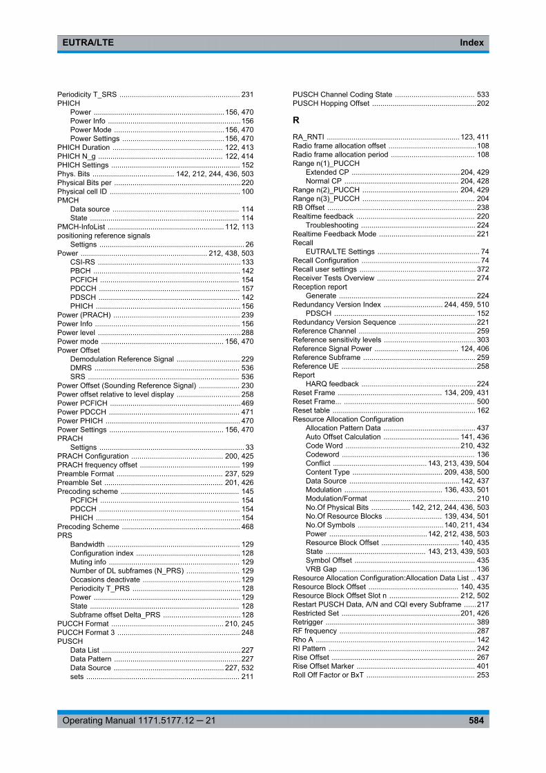
IndexEUTRA/LTE
584Operating Manual 1171.5177.12 ─ 21
Periodicity T_SRS ........................................................... 231PHICH
Power ................................................................156, 470Power Info .................................................................156Power Mode ......................................................156, 470Power Settings ..................................................156, 470
PHICH Duration ...................................................... 122, 413PHICH N_g ............................................................. 122, 414PHICH Settings ............................................................... 152Phys. Bits ........................................ 142, 212, 244, 436, 503Physical Bits per ..............................................................220Physical cell ID ................................................................ 100PMCH
Data source .............................................................. 114State ......................................................................... 114
PMCH-InfoList ......................................................... 112, 113positioning reference signals
Settigns ....................................................................... 26Power .............................................................. 212, 438, 503
CSI-RS ......................................................................133PBCH ........................................................................ 142PCFICH .................................................................... 154PDCCH ..................................................................... 157PDSCH ..................................................................... 142PHICH .......................................................................156
Power (PRACH) .............................................................. 239Power Info ....................................................................... 156Power level ......................................................................288Power mode ............................................................ 156, 470Power Offset
Demodulation Reference Signal ............................... 229DMRS ....................................................................... 536SRS .......................................................................... 536
Power Offset (Sounding Reference Signal) .................... 230Power offset relative to level display ............................... 258Power PCFICH ................................................................469Power PDCCH ................................................................ 471Power PHICH .................................................................. 470Power Settings ........................................................ 156, 470PRACH
Settigns ....................................................................... 33PRACH Configuration ............................................. 200, 425PRACH frequency offset ................................................. 199Preamble Format .................................................... 237, 529Preamble Set .......................................................... 201, 426Precoding scheme .......................................................... 145
PCFICH .................................................................... 154PDCCH ..................................................................... 154PHICH .......................................................................154
Precoding Scheme .......................................................... 468PRS
Bandwidth ................................................................. 129Configuration index ................................................... 128Muting info ................................................................ 129Number of DL subframes (N_PRS) .......................... 129Occasions deactivate ................................................129Periodicity T_PRS .....................................................128Power ........................................................................129State ......................................................................... 128Subframe offset Delta_PRS ......................................128
PUCCH Format ....................................................... 210, 245PUCCH Format 3 ............................................................ 248PUSCH
Data List ....................................................................227Data Pattern ..............................................................227Data Source ...................................................... 227, 532sets ........................................................................... 211
PUSCH Channel Coding State ....................................... 533PUSCH Hopping Offset ...................................................202
R
RA_RNTI ................................................................. 123, 411Radio frame allocation offset ...........................................108Radio frame allocation period ......................................... 108Range n(1)_PUCCH
Extended CP .....................................................204, 429Normal CP ........................................................ 204, 428
Range n(2)_PUCCH ............................................... 204, 429Range n(3)_PUCCH ....................................................... 204RB Offset .........................................................................238Realtime feedback .......................................................... 220
Troubleshooting ........................................................ 224Realtime Feedback Mode ............................................... 221Recall
EUTRA/LTE Settings .................................................. 74Recall Configuration .......................................................... 74Recall user settings ......................................................... 372Receiver Tests Overview ................................................ 274Reception report
Generate ................................................................... 224Redundancy Version Index ............................. 244, 459, 510
PDSCH ..................................................................... 152Redundancy Version Sequence ......................................221Reference Channel ......................................................... 259Reference sensitivity levels ............................................. 303Reference Signal Power ......................................... 124, 406Reference Subframe ....................................................... 259Reference UE ..................................................................258Report
HARQ feedback ........................................................ 224Reset Frame ................................................... 134, 209, 431Reset Frame... ................................................................ 500Reset table ...................................................................... 162Resource Allocation Configuration
Allocation Pattern Data ............................................. 437Auto Offset Calculation ..................................... 141, 436Code Word ........................................................210, 432Codeword ................................................................. 136Conflict .............................................. 143, 213, 439, 504Content Type ............................................ 209, 438, 500Data Source ...................................................... 142, 437Modulation ................................................ 136, 433, 501Modulation/Format .................................................... 210No.Of Physical Bits ................... 142, 212, 244, 436, 503No.Of Resource Blocks ............................ 139, 434, 501No.Of Symbols ..........................................140, 211, 434Power ................................................142, 212, 438, 503Resource Block Offset ...................................... 140, 435State ................................................. 143, 213, 439, 503Symbol Offset ........................................................... 435VRB Gap ...................................................................136
Resource Allocation Configuration:Allocation Data List .. 437Resource Block Offset ............................................ 140, 435Resource Block Offset Slot n .................................. 212, 502Restart PUSCH Data, A/N and CQI every Subframe ......217Restricted Set ..........................................................201, 426Retrigger ......................................................................... 389RF frequency ...................................................................287Rho A .............................................................................. 142RI Pattern ........................................................................ 242Rise Offset ...................................................................... 267Rise Offset Marker .......................................................... 401Roll Off Factor or BxT ..................................................... 253
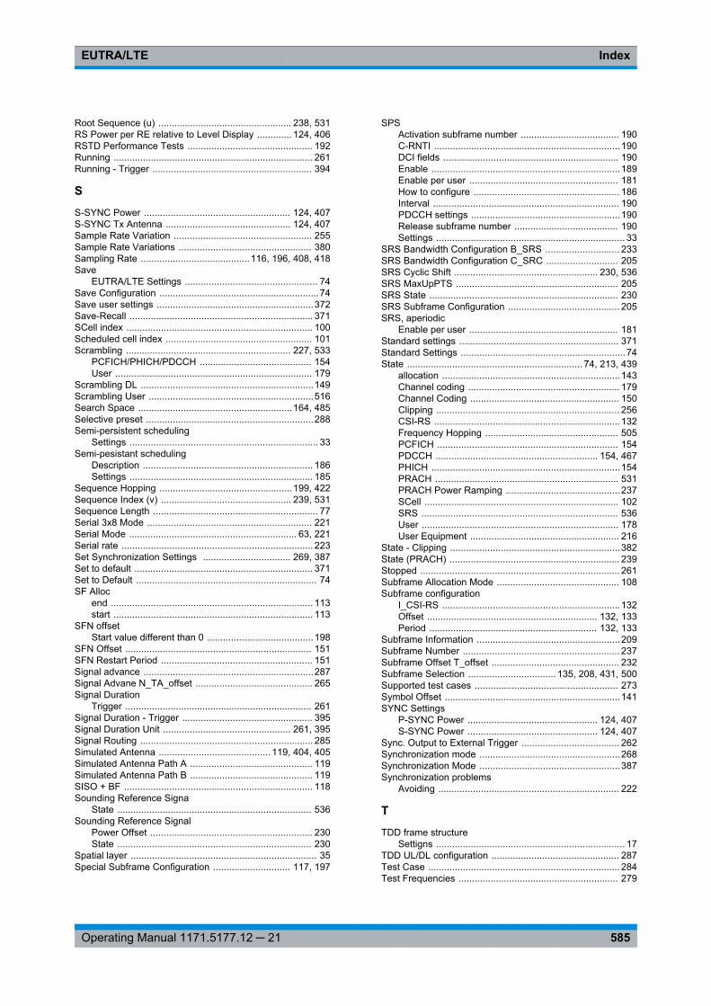
IndexEUTRA/LTE
585Operating Manual 1171.5177.12 ─ 21
Root Sequence (u) .................................................. 238, 531RS Power per RE relative to Level Display ............. 124, 406RSTD Performance Tests ............................................... 192Running ........................................................................... 261Running - Trigger ............................................................ 394
S
S-SYNC Power ....................................................... 124, 407S-SYNC Tx Antenna ............................................... 124, 407Sample Rate Variation .................................................... 255Sample Rate Variations .................................................. 380Sampling Rate .........................................116, 196, 408, 418Save
EUTRA/LTE Settings .................................................. 74Save Configuration ............................................................74Save user settings ...........................................................372Save-Recall ..................................................................... 371SCell index ...................................................................... 100Scheduled cell index ....................................................... 101Scrambling .............................................................. 227, 533
PCFICH/PHICH/PDCCH .......................................... 154User .......................................................................... 179
Scrambling DL .................................................................149Scrambling User ..............................................................516Search Space ..........................................................164, 485Selective preset ...............................................................288Semi-persistent scheduling
Settings ....................................................................... 33Semi-pesistant scheduling
Description ................................................................ 186Settings ..................................................................... 185
Sequence Hopping ..................................................199, 422Sequence Index (v) ................................................. 239, 531Sequence Length .............................................................. 77Serial 3x8 Mode .............................................................. 221Serial Mode ............................................................... 63, 221Serial rate ........................................................................ 223Set Synchronization Settings ................................. 269, 387Set to default ................................................................... 371Set to Default .................................................................... 74SF Alloc
end ............................................................................ 113start ........................................................................... 113
SFN offsetStart value different than 0 ........................................198
SFN Offset ...................................................................... 151SFN Restart Period ......................................................... 151Signal advance ................................................................287Signal Advane N_TA_offset ............................................ 265Signal Duration
Trigger ...................................................................... 261Signal Duration - Trigger ................................................. 395Signal Duration Unit ................................................ 261, 395Signal Routing ................................................................. 285Simulated Antenna .......................................... 119, 404, 405Simulated Antenna Path A .............................................. 119Simulated Antenna Path B .............................................. 119SISO + BF ....................................................................... 118Sounding Reference Signa
State ......................................................................... 536Sounding Reference Signal
Power Offset ............................................................. 230State ......................................................................... 230
Spatial layer ...................................................................... 35Special Subframe Configuration ............................. 117, 197
SPSActivation subframe number ..................................... 190C-RNTI ......................................................................190DCI fields .................................................................. 190Enable .......................................................................189Enable per user ........................................................ 181How to configure ....................................................... 186Interval ...................................................................... 190PDCCH settings ........................................................190Release subframe number ....................................... 190Settings ....................................................................... 33
SRS Bandwidth Configuration B_SRS ............................ 233SRS Bandwidth Configuration C_SRC ........................... 205SRS Cyclic Shift ...................................................... 230, 536SRS MaxUpPTS ............................................................. 205SRS State ....................................................................... 230SRS Subframe Configuration .......................................... 205SRS, aperiodic
Enable per user ........................................................ 181Standard settings ............................................................ 371Standard Settings ..............................................................74State .................................................................. 74, 213, 439
allocation ...................................................................143Channel coding ......................................................... 179Channel Coding ........................................................ 150Clipping ..................................................................... 256CSI-RS ......................................................................132Frequency Hopping .................................................. 505PCFICH .................................................................... 154PDCCH ............................................................. 154, 467PHICH .......................................................................154PRACH ..................................................................... 531PRACH Power Ramping ...........................................237SCell ......................................................................... 102SRS .......................................................................... 536User .......................................................................... 178User Equipment ........................................................ 216
State - Clipping ................................................................382State (PRACH) ................................................................ 239Stopped ........................................................................... 261Subframe Allocation Mode .............................................. 108Subframe configuration
I_CSI-RS ...................................................................132Offset ................................................................ 132, 133Period ............................................................... 132, 133
Subframe Information ......................................................209Subframe Number ........................................................... 237Subframe Offset T_offset ................................................ 232Subframe Selection ................................. 135, 208, 431, 500Supported test cases ...................................................... 273Symbol Offset ..................................................................141SYNC Settings
P-SYNC Power ................................................. 124, 407S-SYNC Power ................................................. 124, 407
Sync. Output to External Trigger ..................................... 262Synchronization mode .....................................................268Synchronization Mode .....................................................387Synchronization problems
Avoiding .................................................................... 222
T
TDD frame structureSettigns ....................................................................... 17
TDD UL/DL configuration ................................................ 287Test Case ........................................................................ 284Test Frequencies ............................................................ 279
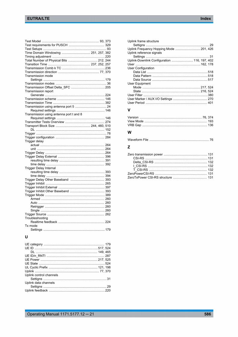
IndexEUTRA/LTE
586Operating Manual 1171.5177.12 ─ 21
Test Model ................................................................ 93, 373Test requirements for PUSCH ........................................ 329Test Setups ....................................................................... 93Time Domain Windowing ................................ 251, 257, 382Timing adjustment ........................................................... 220Total Number of Physical Bits ................................. 212, 244Transition Time ............................................... 237, 252, 257Transmission Comb k TC ................................................236Transmission direction .............................................. 77, 370Transmission mode
Settings ..................................................................... 179Transmission modes ......................................................... 36Transmission Offset Delta_SFC ......................................205Transmission report
Generate ................................................................... 224Transmission scheme ..................................................... 146Transmission Time .......................................................... 382Transmission using antenna port 5 ................................... 24
Required settings ...................................................... 146Transmission using antenna port t and 8
Required settings ...................................................... 146Transmitter Tests Overview ............................................ 274Transport Block Size ....................................... 244, 460, 510
DL ............................................................................. 152Trigger ............................................................................... 78Trigger configuration ....................................................... 284Trigger delay
actual ........................................................................ 264unit ............................................................................ 264
Trigger Delay ...................................................................264Trigger Delay External .................................................... 396
resulting time delay ................................................... 391time delay ................................................................. 392
Trigger Delay Internalresulting time delay ................................................... 393time delay ................................................................. 394
Trigger Delay Other Baseband ...................................... 393Trigger Inhibit .................................................................. 265Trigger Inhibit External .................................................... 397Trigger Inhibit Other Baseband ....................................... 393Trigger Mode ................................................................... 389
Armed ....................................................................... 260Auto .......................................................................... 260Retrigger ................................................................... 260Single ........................................................................ 260
Trigger Source ................................................................ 262Troubleshooting
Realtime feedback .................................................... 224Tx mode
Settings ..................................................................... 179
U
UE category .................................................................... 179UE ID .......................................................................517, 524
DL ..................................................................... 149, 465UE ID/n_RNTI ................................................................. 287UE Power ................................................................ 217, 525UE State .......................................................................... 524UL Cyclic Prefix ....................................................... 121, 198Uplink ........................................................................ 77, 370Uplink control channels
Settigns ....................................................................... 31Uplink data channels
Settigns ....................................................................... 29Uplink feedback ...............................................................220
Uplink frame structureSettigns ....................................................................... 29
Uplink Frequency Hopping Mode ............................ 201, 426Uplink reference signals
Settings ....................................................................... 31Uplink-Downlink Configuration ........................ 116, 197, 402User .........................................................................162, 178User Configuration
Data List ....................................................................518Data Pattern ..............................................................518Data Source .............................................................. 517
User EquipmentMode ................................................................. 217, 524State ................................................................. 216, 524
User Filter ........................................................................380User Marker / AUX I/O Settings ...................................... 270User Period ..................................................................... 401
V
Version ...................................................................... 76, 374View Mode ...................................................................... 193VRB Gap ......................................................................... 136
W
Waveform File ................................................................... 76
Z
Zero transmission power ................................................. 131CSI-RS ......................................................................131Delta_CSI-RS ........................................................... 132I_CSI-RS ...................................................................132T_CSI-RS ................................................................. 132
ZeroPowerCSI-RS .......................................................... 131ZeroTxPower CSI-RS structure ...................................... 131
Recommended