Develop a process to extract BFRs from WEEE polymers – Final report 1
Develop a process to separate brominated flame retardants from WEEE polymers
Final Report
Project code: PLA- 037 Start of research: 1st October 2004 End of Research: 31st May 2006
Authors: Keith Freegard, Gayle Tan & Roger Morton – Axion Recycling Ltd With contributions from: Chris Coggins - Wamtech Dion Froes – DPF Environmental Mark Alger & Peter Cracknell – London Metropolitan University Andreas Maeurer – Fraunhofer IVV Phil Studds and Emily Freer – White Young Green Jaco Huisman – Huisman Recycling Research
Published by: The Waste & Resources Action Programme The Old Academy, 21 Horse Fair, Banbury, Oxon OX16 0AH Tel: 01295 819900 Fax: 01295 819911 www.wrap.org.uk WRAP Business Helpline: Freephone: 0808 100 2040 Date: November 2006 ISBN: 1-84405-315-6
Creating markets for recycled resources

Develop a process to extract BFRs from WEEE polymers – Final report 2
Abstract
This final report summarises the practical trials and process design work conducted during a three phase project funded by WRAP to develop a process to separate brominated flame retardants (BFRs) from waste electrical and electronic equipment (WEEE) polymers. The work shows that the modified Creasolv1 process for extraction of brominated flame retardants from WEEE polymers has potential to be commercially viable in the UK context at a throughput of 10,000te/year. The Creasolv process was originally developed by Fraunhofer IVV in Germany and has been modified further in the course of this project in collaboration with Fraunhofer IVV. The Creasolv process will remove most BFR types from styrenic WEEE polymers. Work done for this project has shown that styrenic polymers constitute over half of collectable WEEE polymers and that they contain the great majority of the BFRs found in WEEE thermoplastics. It is has not been tested with the newer BFR types such as brominated epoxy oligomers because these are not yet found in significant quantities in real WEEE. A second process called Centrevap has also been developed in the course of this project and tested at technical scale. Tests have shown that it cannot achieve significant reductions in BFR content. However it does offer good potential as a robust, flexible and relatively cost-effective process for removal of insoluble impurities down to submicron size from a wide range of polymer types. Both processes should be able to compete with landfill disposal or incineration (£45/te gate fee) as treatment methods for segregated polymer streams. Creasolv will compete for BFR removal, Centrevap should be suitable for removal of other insoluble impurities. They will compete with export of the WEEE polymer outside the EU (current sales value of around £100/te) if the finished high grade compounded recyclate can be sold at about 80% of virgin compound price. Environmental impact comparisons conducted during Phase 2 of the project and updated for this final report indicate that both of the recommended processes have a net environmental gain across all environmental impact categories and that the proposed treatment routes are a substantially better environmental option than landfill and also a better option than incineration with energy recovery. The report recommends that the modified Creasolv process developed during this project is the best commercial and environmental option for treatment of styrenic WEEE polymers containing brominated flame retardents. While steps have been taken to ensure its accuracy, WRAP cannot accept responsibility or be held liable to any person for any loss or damage arising out of or in connection with this information being accurate, incomplete of misleading. For more detail, please refer to our Terms & Conditions on our website - www.wrap.org.uk
1 Creasolv® is a registered trade name of CreaCycle GmbH. Throughout this report, where the term ‘Creasolv’ is used it refers to the registered trade name Creasolv®.
Develop a process to extract BFRs from WEEE polymers – Final report 3
Executive summary
This is the final report for a project to develop a process to separate brominated flame retardants from WEEE polymers. It summarises the practical trials and process design work which were conducted during the project. The European WEEE Directive encourages closed loop recycling by electronics manufacturers (but does not make it mandatory in the first implementation of the directive). The Waste Resources Action Programme (WRAP) www.wrap.org.uk is a major UK Government programme established to accelerate resource efficiency by creating stable and efficient markets for recycled materials and products and removing barriers to waste minimisation, re-use and recycling. Resource efficiency means making better use of resources by reducing the volume of waste generated and maximising the use of recovered materials in the economy, in products and process. WRAP is a not-for-profit company limited by guarantee, backed by funding from DEFRA, DTI and the devolved administrations of Scotland, Wales and Northern Ireland. WRAP works with the public, private and community sectors throughout the EU with the aim of promoting resource efficiency within the UK. WRAP has identified that one of the barriers to closed loop recycling of polymers from waste electrical and electronic equipment (WEEE) is the need to remove unwanted additives from the polymers before they can be re-used. An important group of additives which need to be removed are the brominated flame retardants (BFRs). Two of these, Penta and Octa Bromodiphenylether (BDE) are already banned from use in new products by the ‘Penta Directive’. Other brominated flame retardants are not restricted by European law but several major European electronics manufacturers have still decided to restrict their use to below 0.1% in new electronic products. WRAP initiated this project to develop a process to separate brominated flame retardants from mixed WEEE polymers. WRAP expects that if a commercially viable treatment process can be developed it will help to encourage increased recycling of WEEE polymers and thereby increase diversion of these materials from landfill. Axion Recycling www.axionrecycling.com has been engaged by WRAP to lead the project. It worked with academic and commercial collaborators as appropriate to conduct the research. The industry that is developing in the UK for the treatment of WEEE falls into two distinct types of operation:
• Large-scale, bulk shredding plants producing a mixed stream of polymers and other materials • Manual dismantling systems generating a stream of individual polymer components, usually relatively clean and
partially sorted by polymer type In order to find a ‘total process’ solution for the removal of BFRs from these different plastic waste streams, it is also necessary to assess the costs, efficiency and yields of the polymer identification and mechanical sorting techniques that could be used to separate the valuable non-BFR polymers for direct recycling and deliver a concentrated feed of BFR-containing polymers to a BFR-treatment process. The project has therefore researched and tested both separation and sorting techniques for WEEE polymers and the BFR treatment processes themselves. The project was organised in three phases with a review of objectives at the end of each phase:
1. Literature search and consultations with the electrical and electronics industry 2. Lab scale testing and economic/ environmental evaluation of a range of alternative treatment solutions 3. More in-depth testing and process design for the most promising solution followed by dissemination of the
results of the work Three interim reports were published by WRAP during the course of the project and are available for download from the WRAP website www.wrap.org.uk/publications . This final report summarises the conclusions of the interim reports. It includes new results from the final large scale trials of the two most promising process options and updates of the commercial and environmental impacts of these options.
Develop a process to extract BFRs from WEEE polymers – Final report 4
Readers wishing to review all of the detailed project work will need to read all three interim reports in conjunction with this final report. Note that the BFR polymer treatment processes that were developed in the course of this study are still likely to require 2-4 years of further development before they can be deployed commercially at large scale. Until commercially viable treatment processes are available, the options available for disposal of BFR-containing WEEE polymers will be export for recycling outside the EU, landfill or incineration with energy recovery. The conclusions and recommendations of the project are as follows:
• Mechanical separation followed by a solvent-based process that removes brominated flame retardant additives from the BFR-containing polymers is likely to be a better environmental and commercial option for treatment of WEEE plastics than landfill, incineration with energy recovery or feedstock recycling
• Tests of the key elements of the ‘Centrevap’ process have demonstrated that it can remove insoluble additives down to around 0.5 micron provided that the density of the additive particles is significantly greater than 0.95. For example, the process removed antimony trioxide additive very efficiently. However the solvent combination used for the Centrevap process trials did not allow the removal of brominated flame retardants to the standard set for this project because the BFRs were partially soluble in the chosen solvent.
• Although the Centrevap process as tested during this project is potentially attractive for producing clean particle-free polymers it is not appropriate for BFR removal – the specific objective of this project.
• High quality, almost BFR-free recycled HIPS/ABS polymer has been produced in the course of the project by the Creasolv process from real WEEE polymers in tonnage-scale process trials.
• Mechanical properties of the recyclates produced by both the Creasolv and Centrevap process routes were good. However there was a significant reduction in the impact strength of the Creasolv recyclate.
• Removal of residual solvent in the final product is important for both process options and requires further process development.
• The Creasolv process should be commercially viable for treatment of segregated BFR-containing styrenic polymers from WEEE in the UK context if it can sell the recyclate at 60% of virgin compound price (around £560/te) and charge a gate fee of £45/te to compete with landfill.
• If the Creasolv process can produce really high grade compound valued at 80% of virgin material (£750/te) then it should be commercially viable when competing with current export prices to China for the input material (around £100/te). Recent market research by Axion indicates that end-users are increasingly prepared to pay 80-90% of virgin price for high grade recycled polymers.
• A combination of the Creasolv and Centrevap processes, although more expensive in capital cost terms, has potential to provide the benefits of both process options, delivering finished polymer with very low levels of BFR content and essentially particle-free.
• The process know-how generated during this project is available to license in the UK on commercial terms from WRAP and Fraunhofer IVV.
Develop a process to extract BFRs from WEEE polymers – Final report 5
Contents
Abstract ...................................................................................................................................................................2 Executive summary ...................................................................................................................................................3 Contents...................................................................................................................................................................5 1. Purpose of this report ....................................................................................................................................... 6 2. Objectives ........................................................................................................................................................8 3. Method ............................................................................................................................................................9 4. Reporting ....................................................................................................................................................... 11 5. Types of BFR used now and in the past............................................................................................................ 12 6. Likely mix of polymers in WEEE ....................................................................................................................... 18 7. Environmental effects of BFRs and related additives in WEEE polymers.............................................................. 24 8. EU and UK legislation applying to polymers containing BFRs.............................................................................. 33 9. E+E manufacturer market survey .................................................................................................................... 47 10. WEEE polymer compatibility with new EEE polymers.................................................................................... 54 11. Methods to detect and measure BFR type and concentration in WEEE polymers ............................................ 59 12. WEEE polymer identification and separation trials ........................................................................................ 72 13. Reprocessing options for plastics containing BFRs........................................................................................ 85 14. Process design assumptions ....................................................................................................................... 94 15. Short-listed process options........................................................................................................................ 97 16. Creasolv process trials ............................................................................................................................... 99 17. Centrevap process trials ........................................................................................................................... 121 18. Combined Creasolv/Centrevap process design option................................................................................. 142 19. Incineration............................................................................................................................................. 146 20. Material property testing .......................................................................................................................... 150 21. Environmental impact assessment ............................................................................................................ 157 22. Sensitivity analysis................................................................................................................................... 166 23. Conclusions and recommendations ........................................................................................................... 167 Appendix 1 Recent developments in EU and UK legislation relating to polymers containing BFRs Appendix 2 Material test results from London Metropolitan University for WEEE polymers produced during the trials Appendix 3 Evaluation of Ionic Liquid, Antisolv and RGS90 process options Appendix 4 Detail of Phase 2 development of Creasolv and Centrevap process options Appendix 5 Detail of White Young Green and Huisman environmental impact assessments
Develop a process to extract BFRs from WEEE polymers – Final report 6
1. Purpose of this report
This is the final report for the WRAP project, ‘Develop a process to separate Brominated Flame Retardents from WEEE Polymers’ The project was funded by WRAP as a result of a call for R&D proposals to find ways to treat polymers containing brominated flame retardants in line with the requirements of the WEEE Directive. Flame retardants are the most important group of plastics additives having a total market value of 9 billion Euros/year. Brominated flame retardants (BFR’s) have the highest market share by value and represent 11.8% of the market share by volume2. Over 75 different types of BFRs are produced with the majority being used in electrical and electronic applications. It is estimated that around 7% by weight of all WEEE plastics contain brominated flame retardants, with the majority concentrated in brown goods and small WEEE items3. The WEEE Directive requires the separation of plastics containing brominated flame retardents prior to recycling, energy recovery or disposal. At present no commercially viable processes are available to extract BFRs from WEEE plastics and there are few options available to separate polymers containing BFRs from polymers that do not contain BFRs. Some polymers containing BFRs are currently processed in non-ferrous metal smelters, where separation is not required and the majority are landfilled. WRAP initiated this project in order to find commercially viable ways to remove BFRs from WEEE polymers and thereby create a better opportunities for general recycling of WEEE polymers and in particular for closed loop recycling of WEEE polymers back into new E+E equipment.
2 ‘Flame retardants – FAQs’, CEFIC information booklet, downloadable from www.cefic-efra.com 3 ‘Analysis of plastics consumption and recovery in Europe’ – detail workings, Sofres Consulting, 2003
Develop a process to extract BFRs from WEEE polymers – Final report 7
Acknowledgements A large number of collaborators have contributed to this study. They include: Dr Bruno Krummenacher and Dr Aafko Schanssema, Plastics Europe Dr Mercia Gick, British Plastics Federation Mark Burstall, Recycling Concepts Stephen Daughtrey and Grant Barton, Bruce Metals Ltd Lein Tange, European Brominated Flame Retardents Industry Panel (EBFRIP) David Buszard, Great Lakes Chemical Co Dr Franck Mark, Dow Europe Dr Andreas Maeurer and Martin Schlummer, Fraunhofer IVV, Freising, Germany Ian Lund, Manrochem Ltd Dr Lucy Tovell, Wilson Gunn Patent Agents Peter Evans and Karl Bodenhofer, Sony Visual Products Europe Dr Andreas Hornung, Forschungzentrum, Karlsruhe, Germany Professor Chris Coggins - Wamtech Dion Froes, DPF Environmental Professor Martyn Poliakoff, Dr Ben Walsh, Dr Paul Hamley, Dr Gonzalo Givaja, Dept of Chemistry, Nottingham University Professor Sue Grimes, Dr Lina Mehta and Dr Huma Lateef, Centre for Environmental Research, Brunel University Ken Norman, EMR Dr David Pyke Norbert Fraunholz, Recycling Concepts, Netherlands Dr Tako De Jong, Delft University, Netherlands Dr Rainer Konlecher, Hamos Gmbh, Germany Graham Hearn, Southampton University Dr Wolfgang Becker, Fraunhofer ICT, Pfinztal, Germany Phil Studds and Emily Freer, White Young Green Professor Tony Clifford, Critical Processes Ltd Dr Erik Rasmussen, RGS90 Watech, Denmark Joe Cetti and Ron Sneddon, Mastermagnets Ltd Mark Dowling, BT Chris O’Brien, Brother Industries Roger Freeman, Hampshire Natural Resources Trust Judith Clayman, Paul Denton, Laura Winstanley, Robin Hilder and Stuart Corns, Axion Recycling Dr Jason Mellor and Tony Constable, Ionic Solutions Ltd Hans-Jurg Pfenniger, Mavag AG, Switzerland Dr Hans Peters and Ibrahim Uslu, Buss-SMS, Switzerland Detlef Ullmann, Sven Nitschke and Dr Klaus Mannweiler, Westfalia Separator, Germany Peter Klunder, Formeco, Italy David Jones, Solutex, UK
Develop a process to extract BFRs from WEEE polymers – Final report 8
2. Objectives
Overall objectives of the project were to:
• Set target performance criteria for the BFR separation process to be developed. This was achieved by interviewing a representative group of electrical and electronic equipment manufacturers to establish their criteria for use of WEEE polymer recyclate.
• Identify and test a number of alternative process designs for separation of brominated flame retardants from WEEE polymers.
• Evaluate the alternative process options against alternative disposal routes in terms of: o Technical feasibility o Commercial viability o Environmental impact
• Further develop the most commercially viable process options by practical trials at an appropriate scale. • Disseminate the findings to a broad and relevant audience within the electrical and electronic industry and the
recycling sector
Develop a process to extract BFRs from WEEE polymers – Final report 9
3. Method
The following methodology has been adopted for the project:
• Research the literature for work done to date on BFR removal from plastics. • Interview electronic and electrical product designers to establish target acceptance criteria for the recycled
polymers. This will set the performance targets for the process design phase. • Investigate the available techniques for the identification and sorting of plastics containing BFRs. • Identify all potential processes for removal of BFRs from WEEE polymers • Conduct a detailed evaluation of the above processes, in three phases:
Phase 1: A desk based comparison to screen out unviable options Phase 2: Laboratory scale trials of a shortlist of technologies Phase 3: Larger-scale pilot plant trials of the leading options coupled with commercial and environmental impact assessments
Phase 1:
• Reviewed the literature to identify potential WEEE polymer treatment processes • Reviewed the literature to estimate the likely composition of WEEE polymers that are likely to be collected in
future • Reviewed the legislation governing treatment of WEEE polymers • Assessed the hazards associated with brominated flame retardents likely to be found in WEEE polymers • Conducted a market survey of leading electronics manufacturers to assess likely demand and the specifications
that they would be likely to apply to recycled polymers from the type of process to be developed in the course of this project
Phase 2:
• Tested and assessed a broad range of the WEEE polymer identification and bulk separation techniques that will be required to produce a separated stream of BFR-containing polymers for treatment by the processes to be developed in this project
• Conducted laboratory trials of the key process steps for each of the shortlisted BFR polymer treatment process options
• Prepared outline process description, flowsheet, mass balance and capital cost estimates for each process option at a throughput of 10,000te/yr plastic
• Identified possible markets for the products from the different process options and estimated likely revenues • Prepared initial financial projections with similar assumptions for each option • Conducted an environmental impact assessment for each process option • Compared technical feasibility, economic returns and environmental impact of the process options and, as a
benchmark, compared them also with the alternative disposal routes of landfill and incineration. Phase 3:
• Conducted larger scale and more detailed process optimisation trials for the Creasolv and Centrevap process options using appropriate pilot facilities in order to develop more detailed process design data. These trials were conducted at up to 2500 litre scale.
• Prepared detailed plant flowsheets and capital plant cost estimates. • Updated the commercial and environmental impact assessments for the Creasolv and Centrevap process
options
Develop a process to extract BFRs from WEEE polymers – Final report 10
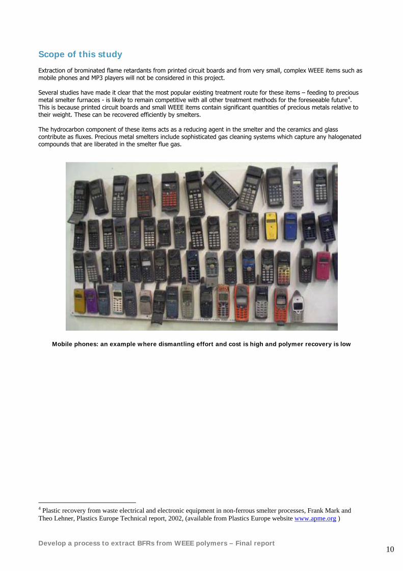
Scope of this study Extraction of brominated flame retardants from printed circuit boards and from very small, complex WEEE items such as mobile phones and MP3 players will not be considered in this project. Several studies have made it clear that the most popular existing treatment route for these items – feeding to precious metal smelter furnaces - is likely to remain competitive with all other treatment methods for the foreseeable future4. This is because printed circuit boards and small WEEE items contain significant quantities of precious metals relative to their weight. These can be recovered efficiently by smelters. The hydrocarbon component of these items acts as a reducing agent in the smelter and the ceramics and glass contribute as fluxes. Precious metal smelters include sophisticated gas cleaning systems which capture any halogenated compounds that are liberated in the smelter flue gas.
Mobile phones: an example where dismantling effort and cost is high and polymer recovery is low
4 Plastic recovery from waste electrical and electronic equipment in non-ferrous smelter processes, Frank Mark and Theo Lehner, Plastics Europe Technical report, 2002, (available from Plastics Europe website www.apme.org )
Develop a process to extract BFRs from WEEE polymers – Final report 11
4. Reporting
The three interim reports on the project and this final report may be downloaded from WRAP’s website: www.wrap.org.uk/publications. The first interim report was published in January 2005. It:
• Provides general information on flame retardants and their applications • Reviews the legislative background • Reviews the existing state of the art in separation and treatment of polymers containing BFRs • Reports on the market survey of electrical and electronic equipment manufacturers • Identifies potential separation and treatment solutions for WEEE polymers containing BFRs • Recommends which process options should be investigated further in phase 2 of the project
The second interim report was published in August 2005. It:
• Describes the treatment solutions for WEEE polymers containing BFRs that were identified for laboratory testing in Phase 2
• Describes the technical evaluation methodology employed during Phase 2 • Summarises the results of the laboratory trials conducted during the technical evaluation • Summarises the results of WEEE polymer separation trials conducted during Phase 2 in order to isolate BFR-
containing WEEE polymers • Presents the 6 outline BFR-treatment process designs that were selected for economic and environmental
impact evaluation as a result of the technical evaluation and process design exercise • Presents the results of the economic and environmental impact comparisons • Recommends which process option should be taken forward for more detailed larger scale testing and
evaluation in Phase 3 of the project. The third interim report was published in March 2006. It:
• Describes the results of practical technical scale testing of the Creasolv and Centrevap process options • Updates the process design work conducted in Phase 2 • Updates the economic evaluations conducted in Phase 2
This final report:
• Summarises the results presented in the three interim reports • Presents the results of large scale trials of the Creasolv and Centrevap process options that were conducted
during the first quarter of 2006 • Updates the process designs for the Creasolv and Centrevap process options based on the results of the large
scale trials • Presents a further process option that combines the best features of the Centrevap and Creasolv processes. • Updates the commercial evaluations and environmental impact assessments that were conducted in Phases 2
and 3 Much of the technical detail of the Creasolv process is not described in the public reports, either because it is confidential information of Fraunhofer Institute Verpackung und Verfahrenstechnik (Fraunhofer IVV) or because it may potentially be patented jointly by WRAP and Fraunhofer IVV. The full technology package will be made available under license to commercial users of the process. Some of the technical detail of the Centrevap process is also not described in this public report because it may be patented and/or retained as licensable knowhow by WRAP.
Develop a process to extract BFRs from WEEE polymers – Final report 12
5. Types of BFR used now and in the past
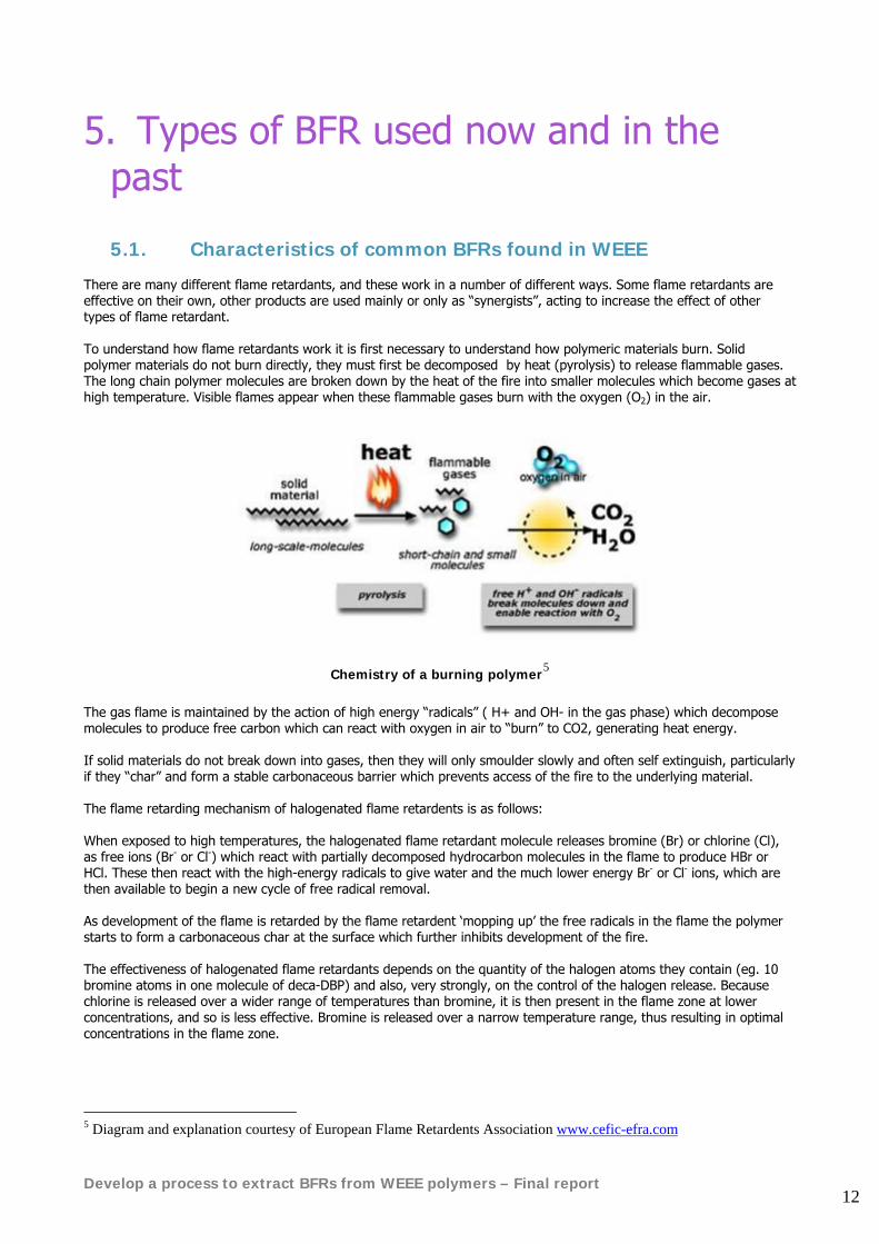
5.1. Characteristics of common BFRs found in WEEE There are many different flame retardants, and these work in a number of different ways. Some flame retardants are effective on their own, other products are used mainly or only as “synergists”, acting to increase the effect of other types of flame retardant. To understand how flame retardants work it is first necessary to understand how polymeric materials burn. Solid polymer materials do not burn directly, they must first be decomposed by heat (pyrolysis) to release flammable gases. The long chain polymer molecules are broken down by the heat of the fire into smaller molecules which become gases at high temperature. Visible flames appear when these flammable gases burn with the oxygen (O2) in the air.
Chemistry of a burning polymer5 The gas flame is maintained by the action of high energy “radicals” ( H+ and OH- in the gas phase) which decompose molecules to produce free carbon which can react with oxygen in air to “burn” to CO2, generating heat energy. If solid materials do not break down into gases, then they will only smoulder slowly and often self extinguish, particularly if they “char” and form a stable carbonaceous barrier which prevents access of the fire to the underlying material. The flame retarding mechanism of halogenated flame retardents is as follows: When exposed to high temperatures, the halogenated flame retardant molecule releases bromine (Br) or chlorine (Cl), as free ions (Br- or Cl-) which react with partially decomposed hydrocarbon molecules in the flame to produce HBr or HCl. These then react with the high-energy radicals to give water and the much lower energy Br- or Cl- ions, which are then available to begin a new cycle of free radical removal. As development of the flame is retarded by the flame retardent ‘mopping up’ the free radicals in the flame the polymer starts to form a carbonaceous char at the surface which further inhibits development of the fire. The effectiveness of halogenated flame retardants depends on the quantity of the halogen atoms they contain (eg. 10 bromine atoms in one molecule of deca-DBP) and also, very strongly, on the control of the halogen release. Because chlorine is released over a wider range of temperatures than bromine, it is then present in the flame zone at lower concentrations, and so is less effective. Bromine is released over a narrow temperature range, thus resulting in optimal concentrations in the flame zone.
5 Diagram and explanation courtesy of European Flame Retardents Association www.cefic-efra.com
Develop a process to extract BFRs from WEEE polymers – Final report 13
Brominated flame retardants are generally compounded in polymers with antimony trioxide. Antimony trioxide does not have flame retarding properties on its own, but is an effective synergist for halogenated flame retardants. It acts as a catalyst, facilitating the breakdown of halogenated flame retardants to active molecules. It also reacts with the halogens to produce volatile antimony halide compounds, which are themselves directly effective in removing the high energy radicals which feed the flame phase of the fire, thus reinforcing the flame suppressing effect of the halogenated flame retardants. When added to PVC, antimony trioxide acts to suppress flames by activating the chlorine present in the plastic itself. BFR’s are mostly used in electronics and electrical equipment where they can be found in plastic housings, connectors and printed circuit boards. They can also be found in wire and cable insulation. Common applications are: There are at least 75 different types of commercially available BFRs but only 30-40 are widely used in electrical and electronic (E&E) equipment 6 7. They are added to E&E plastics in powder or pellet form. From a recycling point of view brominated flame retardants fall into two broad groups; ‘Backbone’ flame retardents and ‘Matrix’ flame retardents:
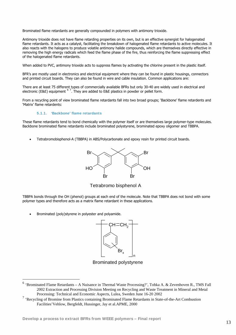
5.1.1. ‘Backbone’ flame retardants These flame retardants tend to bond chemically with the polymer itself or are themselves large polymer-type molecules. Backbone brominated flame retardants include brominated polystyrene, brominated epoxy oligomer and TBBPA.
• Tetrabromobisphenol-A (TBBPA) in ABS/Polycarbonate and epoxy resin for printed circuit boards.
Br
HOBr Br
OH
Br
Tetrabromo bisphenol A TBBPA bonds through the OH (phenol) groups at each end of the molecule. Note that TBBPA does not bond with some polymer types and therefore acts as a matrix flame retardant in these applications.
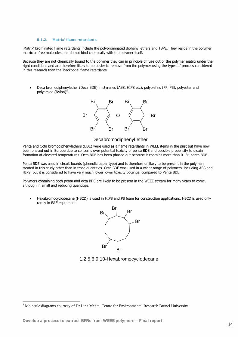
• Brominated (poly)styrene in polyester and polyamide.
CH CH2
Brxn
Brominated polystyrene
6 ‘Brominated Flame Retardants – A Nuisance in Thermal Waste Processing?’, Tohka A. & Zevenhoven R., TMS Fall
2002 Extraction and Processing Division Meeting on Recycling and Waste Treatment in Mineral and Metal Processing: Technical and Economic Aspects, Lulea, Sweden June 16-20 2002
7 ‘Recycling of Bromine from Plastics containing Brominated Flame Retardants in State-of-the-Art Combustion Facilities’Vehlow, Bergfeldt, Hussinger, Jay et al.APME, 2000
Develop a process to extract BFRs from WEEE polymers – Final report 14
5.1.2. ‘Matrix’ flame retardants ‘Matrix’ brominated flame retardants include the polybrominated diphenyl ethers and TBPE. They reside in the polymer matrix as free molecules and do not bind chemically with the polymer itself. Because they are not chemically bound to the polymer they can in principle diffuse out of the polymer matrix under the right conditions and are therefore likely to be easier to remove from the polymer using the types of process considered in this research than the ‘backbone’ flame retardants.
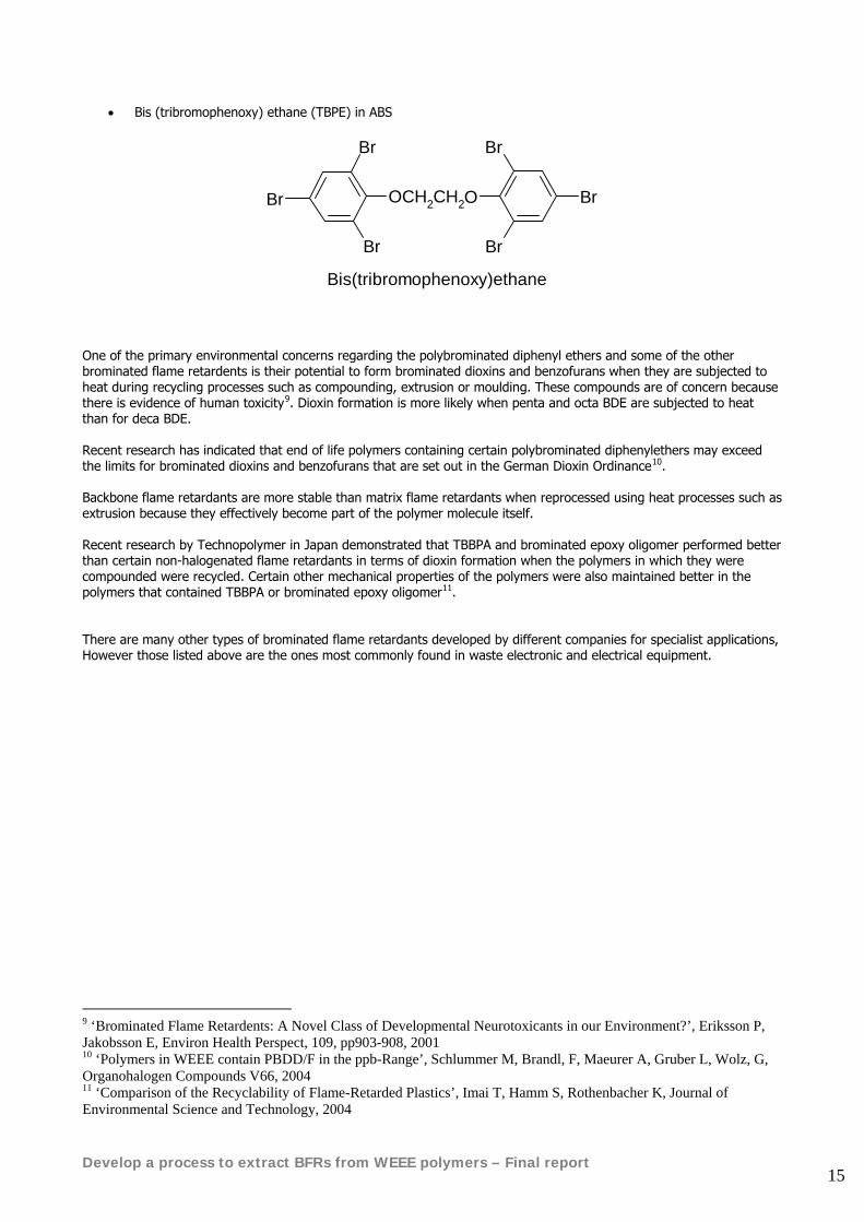
• Deca bromodiphenylether (Deca BDE) in styrenes (ABS, HIPS etc), polyolefins (PP, PE), polyester and polyamide (Nylon)8.
BrBr
Br
Br Br
O
Br Br
Br
BrBr
Decabromodiphenyl ether Penta and Octa bromodiphenylethers (BDE) were used as a flame retardants in WEEE items in the past but have now been phased out in Europe due to concerns over potential toxicity of penta BDE and possible propensity to dioxin formation at elevated temperatures. Octa BDE has been phased out because it contains more than 0.1% penta BDE. Penta BDE was used in circuit boards (phenolic paper type) and is therefore unlikely to be present in the polymers treated in this study other than in trace quantities. Octa BDE was used in a wider range of polymers, including ABS and HIPS, but it is considered to have very much lower lower toxicity potential compared to Penta BDE. Polymers containing both penta and octa BDE are likely to be present in the WEEE stream for many years to come, although in small and reducing quantities.
• Hexabromocyclodecane (HBCD) is used in HIPS and PS foam for construction applications. HBCD is used only rarely in E&E equipment.
Br
BrBr
Br
BrBr
1,2,5,6,9,10-Hexabromocyclodecane
8 Molecule diagrams courtesy of Dr Lina Mehta, Centre for Environmental Research Brunel University
Develop a process to extract BFRs from WEEE polymers – Final report 15
• Bis (tribromophenoxy) ethane (TBPE) in ABS
Br
Br
Br
OCH2CH2
Br
Br
Br
O
Bis(tribromophenoxy)ethane
One of the primary environmental concerns regarding the polybrominated diphenyl ethers and some of the other brominated flame retardents is their potential to form brominated dioxins and benzofurans when they are subjected to heat during recycling processes such as compounding, extrusion or moulding. These compounds are of concern because there is evidence of human toxicity9. Dioxin formation is more likely when penta and octa BDE are subjected to heat than for deca BDE. Recent research has indicated that end of life polymers containing certain polybrominated diphenylethers may exceed the limits for brominated dioxins and benzofurans that are set out in the German Dioxin Ordinance10. Backbone flame retardants are more stable than matrix flame retardants when reprocessed using heat processes such as extrusion because they effectively become part of the polymer molecule itself. Recent research by Technopolymer in Japan demonstrated that TBBPA and brominated epoxy oligomer performed better than certain non-halogenated flame retardants in terms of dioxin formation when the polymers in which they were compounded were recycled. Certain other mechanical properties of the polymers were also maintained better in the polymers that contained TBBPA or brominated epoxy oligomer11. There are many other types of brominated flame retardants developed by different companies for specialist applications, However those listed above are the ones most commonly found in waste electronic and electrical equipment.
9 ‘Brominated Flame Retardents: A Novel Class of Developmental Neurotoxicants in our Environment?’, Eriksson P, Jakobsson E, Environ Health Perspect, 109, pp903-908, 2001 10 ‘Polymers in WEEE contain PBDD/F in the ppb-Range’, Schlummer M, Brandl, F, Maeurer A, Gruber L, Wolz, G, Organohalogen Compounds V66, 2004 11 ‘Comparison of the Recyclability of Flame-Retarded Plastics’, Imai T, Hamm S, Rothenbacher K, Journal of Environmental Science and Technology, 2004
Develop a process to extract BFRs from WEEE polymers – Final report 16
5.2. Assessment of likely concentrations by polymer type and typical synergist additives found alongside them
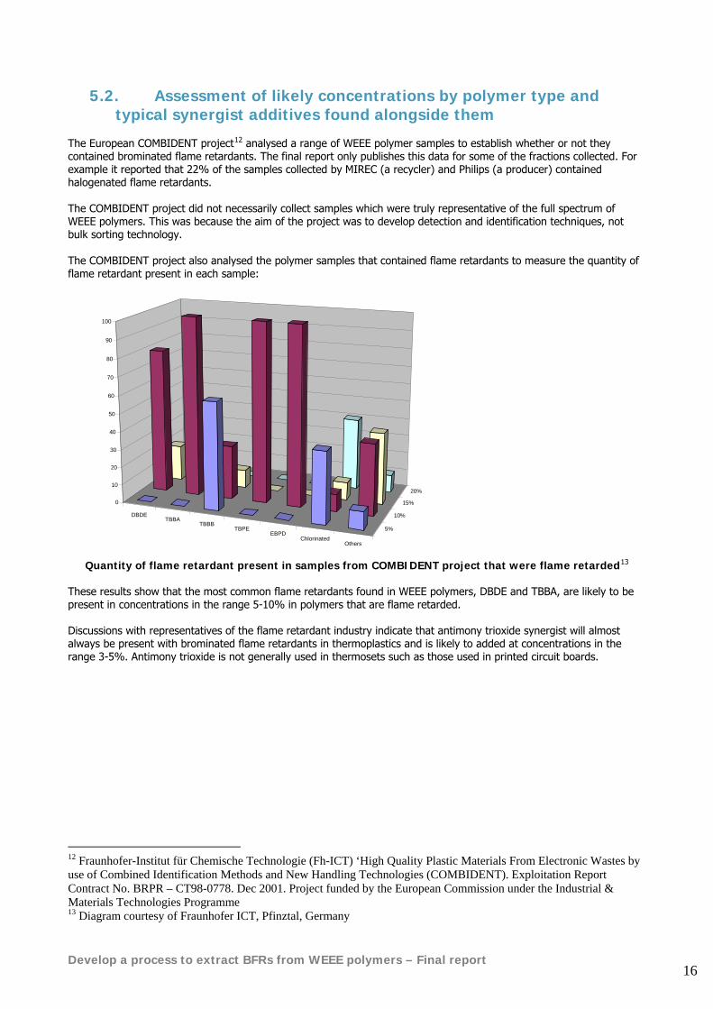
The European COMBIDENT project12 analysed a range of WEEE polymer samples to establish whether or not they contained brominated flame retardants. The final report only publishes this data for some of the fractions collected. For example it reported that 22% of the samples collected by MIREC (a recycler) and Philips (a producer) contained halogenated flame retardants. The COMBIDENT project did not necessarily collect samples which were truly representative of the full spectrum of WEEE polymers. This was because the aim of the project was to develop detection and identification techniques, not bulk sorting technology. The COMBIDENT project also analysed the polymer samples that contained flame retardants to measure the quantity of flame retardant present in each sample:
DBDETBBA
TBBBTBPE
EBPDChlorinated
Others
5%
10%
15%
20%
0
10
20
30
40
50
60
70
80
90
100
Quantity of flame retardant present in samples from COMBIDENT project that were flame retarded13
These results show that the most common flame retardants found in WEEE polymers, DBDE and TBBA, are likely to be present in concentrations in the range 5-10% in polymers that are flame retarded. Discussions with representatives of the flame retardant industry indicate that antimony trioxide synergist will almost always be present with brominated flame retardants in thermoplastics and is likely to added at concentrations in the range 3-5%. Antimony trioxide is not generally used in thermosets such as those used in printed circuit boards.
12 Fraunhofer-Institut für Chemische Technologie (Fh-ICT) ‘High Quality Plastic Materials From Electronic Wastes by use of Combined Identification Methods and New Handling Technologies (COMBIDENT). Exploitation Report Contract No. BRPR – CT98-0778. Dec 2001. Project funded by the European Commission under the Industrial & Materials Technologies Programme 13 Diagram courtesy of Fraunhofer ICT, Pfinztal, Germany
Develop a process to extract BFRs from WEEE polymers – Final report 17
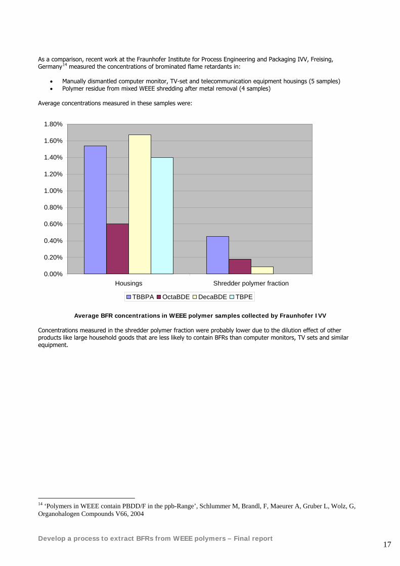
As a comparison, recent work at the Fraunhofer Institute for Process Engineering and Packaging IVV, Freising, Germany14 measured the concentrations of brominated flame retardants in:
• Manually dismantled computer monitor, TV-set and telecommunication equipment housings (5 samples) • Polymer residue from mixed WEEE shredding after metal removal (4 samples)
Average concentrations measured in these samples were:
0.00%
0.20%
0.40%
0.60%
0.80%
1.00%
1.20%
1.40%
1.60%
1.80%
Housings Shredder polymer fraction
TBBPA OctaBDE DecaBDE TBPE
Average BFR concentrations in WEEE polymer samples collected by Fraunhofer IVV
Concentrations measured in the shredder polymer fraction were probably lower due to the dilution effect of other products like large household goods that are less likely to contain BFRs than computer monitors, TV sets and similar equipment.
14 ‘Polymers in WEEE contain PBDD/F in the ppb-Range’, Schlummer M, Brandl, F, Maeurer A, Gruber L, Wolz, G, Organohalogen Compounds V66, 2004
Develop a process to extract BFRs from WEEE polymers – Final report 18
6. Likely mix of polymers in WEEE
WEEE items contain a complex mix of materials including a range of different, often incompatible, polymer types. This complicates the task of recycling WEEE.
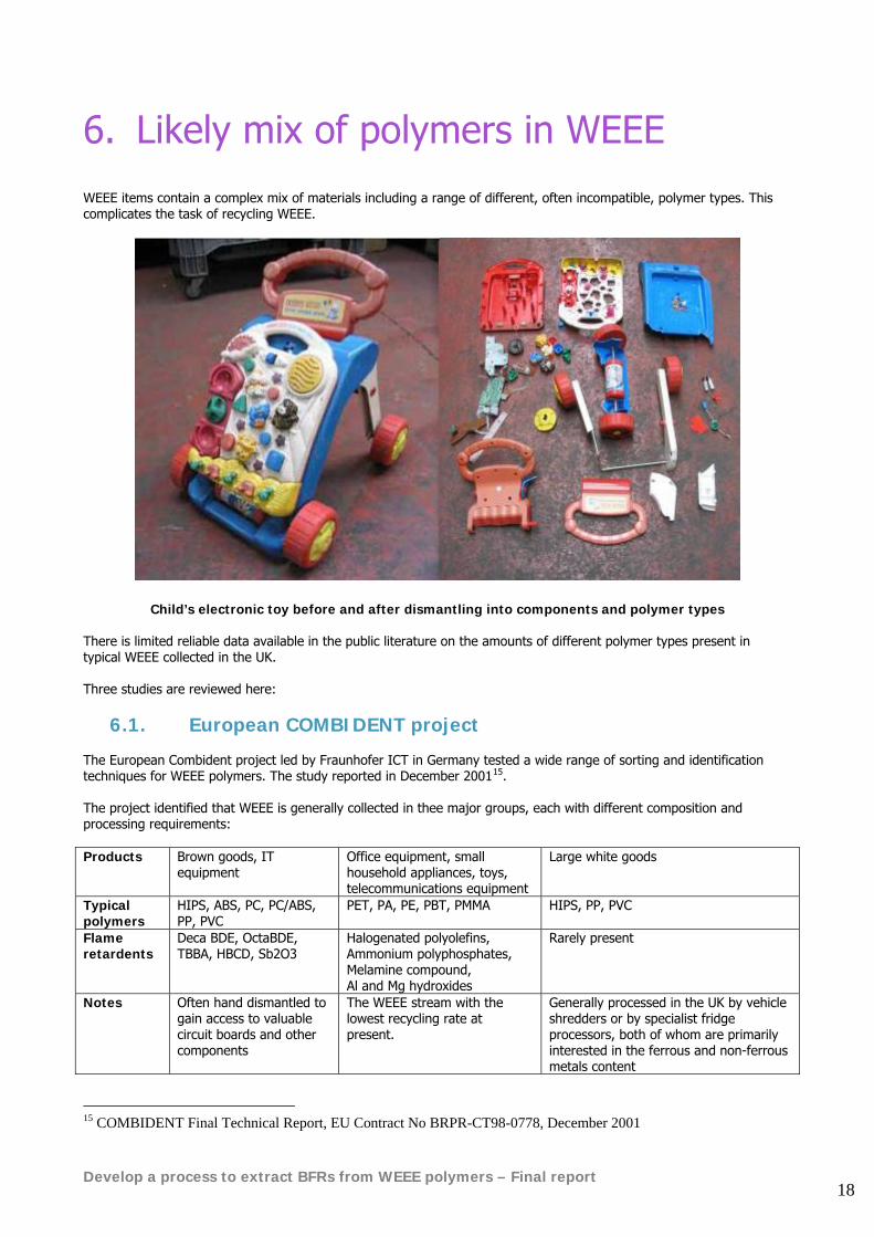
Child’s electronic toy before and after dismantling into components and polymer types There is limited reliable data available in the public literature on the amounts of different polymer types present in typical WEEE collected in the UK. Three studies are reviewed here:
6.1. European COMBIDENT project The European Combident project led by Fraunhofer ICT in Germany tested a wide range of sorting and identification techniques for WEEE polymers. The study reported in December 200115. The project identified that WEEE is generally collected in thee major groups, each with different composition and processing requirements: Products Brown goods, IT
equipment Office equipment, small household appliances, toys, telecommunications equipment
Large white goods
Typical polymers
HIPS, ABS, PC, PC/ABS, PP, PVC
PET, PA, PE, PBT, PMMA HIPS, PP, PVC
Flame retardents
Deca BDE, OctaBDE, TBBA, HBCD, Sb2O3
Halogenated polyolefins, Ammonium polyphosphates, Melamine compound, Al and Mg hydroxides
Rarely present
Notes Often hand dismantled to gain access to valuable circuit boards and other components
The WEEE stream with the lowest recycling rate at present.
Generally processed in the UK by vehicle shredders or by specialist fridge processors, both of whom are primarily interested in the ferrous and non-ferrous metals content
15 COMBIDENT Final Technical Report, EU Contract No BRPR-CT98-0778, December 2001
Develop a process to extract BFRs from WEEE polymers – Final report 19
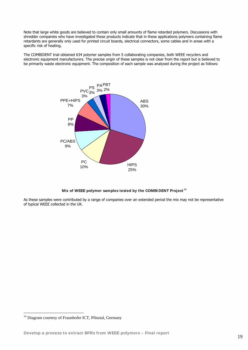
Note that large white goods are believed to contain only small amounts of flame retarded polymers. Discussions with shredder companies who have investigated these products indicate that in these applications polymers containing flame retardants are generally only used for printed circuit boards, electrical connectors, some cables and in areas with a specific risk of heating. The COMBIDENT trial obtained 634 polymer samples from 5 collaborating companies, both WEEE recyclers and electronic equipment manufacturers. The precise origin of these samples is not clear from the report but is believed to be primarily waste electronic equipment. The composition of each sample was analysed during the project as follows:
ABS30%
HIPS25%
PC10%
PC/ABS9%
PP8%
PPE+HIPS7%
PVC3%
PS3%
PA3%
PBT2%
Mix of WEEE polymer samples tested by the COMBIDENT Project16
As these samples were contributed by a range of companies over an extended period the mix may not be representative of typical WEEE collected in the UK.
16 Diagram courtesy of Fraunhofer ICT, Pfinztal, Germany
Develop a process to extract BFRs from WEEE polymers – Final report 20
6.2. UK small household WEEE recycling project for Hampshire Natural Resources Trust
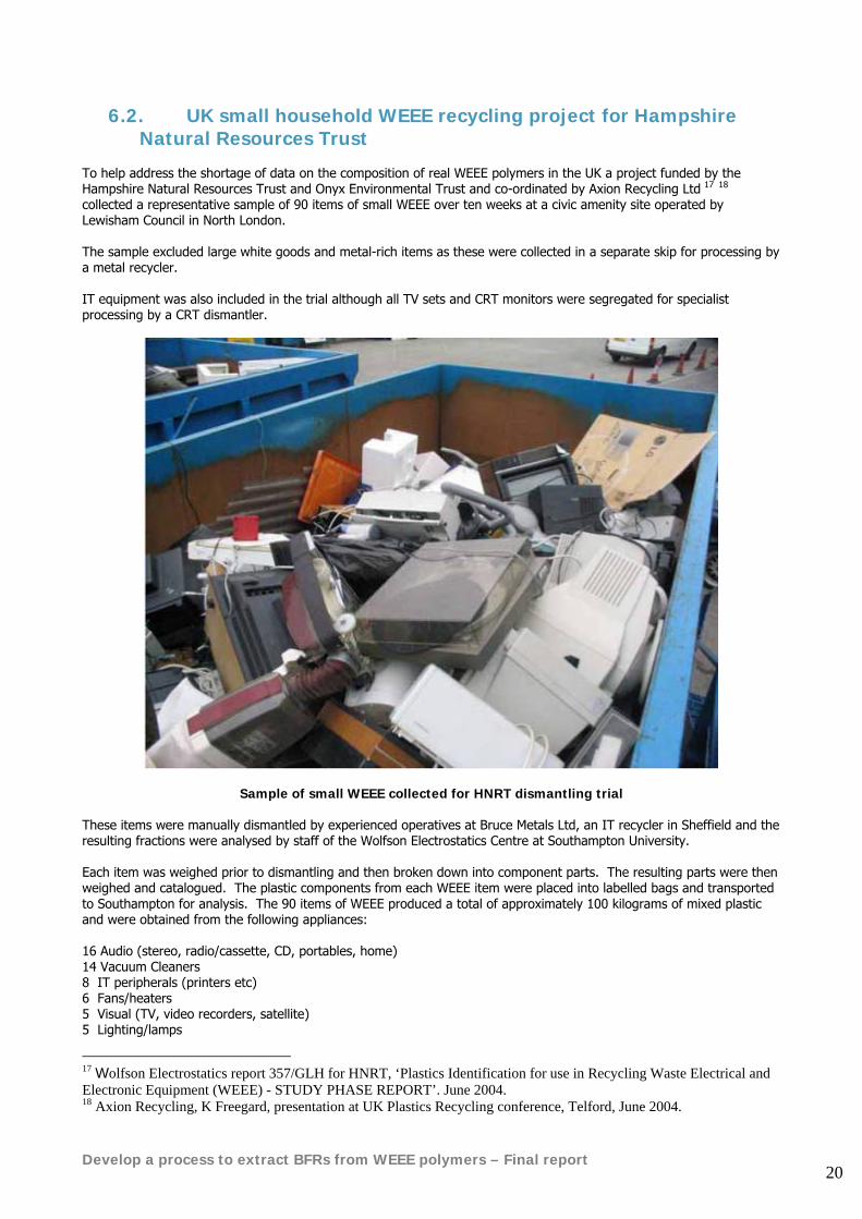
To help address the shortage of data on the composition of real WEEE polymers in the UK a project funded by the Hampshire Natural Resources Trust and Onyx Environmental Trust and co-ordinated by Axion Recycling Ltd 17 18 collected a representative sample of 90 items of small WEEE over ten weeks at a civic amenity site operated by Lewisham Council in North London. The sample excluded large white goods and metal-rich items as these were collected in a separate skip for processing by a metal recycler. IT equipment was also included in the trial although all TV sets and CRT monitors were segregated for specialist processing by a CRT dismantler.
Sample of small WEEE collected for HNRT dismantling trial These items were manually dismantled by experienced operatives at Bruce Metals Ltd, an IT recycler in Sheffield and the resulting fractions were analysed by staff of the Wolfson Electrostatics Centre at Southampton University. Each item was weighed prior to dismantling and then broken down into component parts. The resulting parts were then weighed and catalogued. The plastic components from each WEEE item were placed into labelled bags and transported to Southampton for analysis. The 90 items of WEEE produced a total of approximately 100 kilograms of mixed plastic and were obtained from the following appliances: 16 Audio (stereo, radio/cassette, CD, portables, home) 14 Vacuum Cleaners 8 IT peripherals (printers etc) 6 Fans/heaters 5 Visual (TV, video recorders, satellite) 5 Lighting/lamps
17 Wolfson Electrostatics report 357/GLH for HNRT, ‘Plastics Identification for use in Recycling Waste Electrical and Electronic Equipment (WEEE) - STUDY PHASE REPORT’. June 2004. 18 Axion Recycling, K Freegard, presentation at UK Plastics Recycling conference, Telford, June 2004.
Develop a process to extract BFRs from WEEE polymers – Final report 21
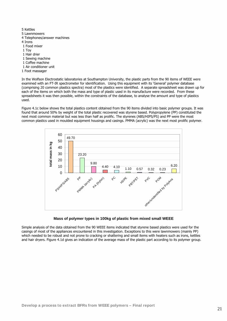
5 Kettles 5 Lawnmowers 4 Telephones/answer machines 4 Irons 1 Food mixer 1 Toy 1 Hair drier 1 Sewing machine 1 Coffee machine 1 Air conditioner unit 1 Foot massager In the Wolfson Electrostatic laboratories at Southampton University, the plastic parts from the 90 items of WEEE were examined with an FT-IR spectrometer for identification. Using this equipment with its ‘General’ polymer database (comprising 20 common plastics spectra) most of the plastics were identified. A separate spreadsheet was drawn up for each of the items on which both the mass and type of plastic used in its manufacture were recorded. From these spreadsheets it was then possible, within the constraints of the database, to analyse the amount and type of plastics used. Figure 4.1c below shows the total plastics content obtained from the 90 items divided into basic polymer groups. It was found that around 50% by weight of the total plastic recovered was styrene based. Polypropylene (PP) constituted the next most common material but was less than half as prolific. The styrenes (ABS/HIPS/PS) and PP were the most common plastics used in moulded equipment housings and casings. PMMA (acrylic) was the next most prolific polymer.
49.70
23.20
9.804.40 4.10 1.10 0.57 0.32 0.23
6.20
0102030405060
PS/HIP
S/ABS PP
PMMA (acry
lic)
PA (Nylo
n) PCHDPE
PBT/PET
PVCPOM
other/
uniden
tified b
y Poly
Ana
tota
l mas
s in
kg
Mass of polymer types in 100kg of plastic from mixed small WEEE Simple analysis of the data obtained from the 90 WEEE items indicated that styrene based plastics were used for the casings of most of the appliances encountered in this investigation. Exceptions to this were lawnmowers (mainly PP) which needed to be robust and not prone to cracking or shattering and small items with heaters such as irons, kettles and hair dryers. Figure 4.1d gives an indication of the average mass of the plastic part according to its polymer group.
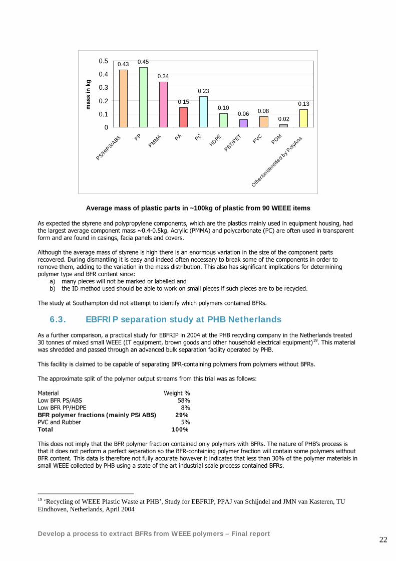
Develop a process to extract BFRs from WEEE polymers – Final report 22
0.43 0.45
0.34
0.15
0.23
0.100.06 0.08
0.02
0.13
0
0.1
0.2
0.3
0.4
0.5
PS/HIP
S/ABS PP
PMMA PA PCHDPE
PBT/PET
PVCPOM
Other/u
nidenti
fied b
y Poly
Ana
mas
s in
kg
Average mass of plastic parts in ~100kg of plastic from 90 WEEE items As expected the styrene and polypropylene components, which are the plastics mainly used in equipment housing, had the largest average component mass ~0.4-0.5kg. Acrylic (PMMA) and polycarbonate (PC) are often used in transparent form and are found in casings, facia panels and covers. Although the average mass of styrene is high there is an enormous variation in the size of the component parts recovered. During dismantling it is easy and indeed often necessary to break some of the components in order to remove them, adding to the variation in the mass distribution. This also has significant implications for determining polymer type and BFR content since:
a) many pieces will not be marked or labelled and b) the ID method used should be able to work on small pieces if such pieces are to be recycled.
The study at Southampton did not attempt to identify which polymers contained BFRs.
6.3. EBFRIP separation study at PHB Netherlands As a further comparison, a practical study for EBFRIP in 2004 at the PHB recycling company in the Netherlands treated 30 tonnes of mixed small WEEE (IT equipment, brown goods and other household electrical equipment)19. This material was shredded and passed through an advanced bulk separation facility operated by PHB. This facility is claimed to be capable of separating BFR-containing polymers from polymers without BFRs. The approximate split of the polymer output streams from this trial was as follows: Material Weight % Low BFR PS/ABS 58% Low BFR PP/HDPE 8% BFR polymer fractions (mainly PS/ABS) 29%PVC and Rubber 5% Total 100% This does not imply that the BFR polymer fraction contained only polymers with BFRs. The nature of PHB’s process is that it does not perform a perfect separation so the BFR-containing polymer fraction will contain some polymers without BFR content. This data is therefore not fully accurate however it indicates that less than 30% of the polymer materials in small WEEE collected by PHB using a state of the art industrial scale process contained BFRs.
19 ‘Recycling of WEEE Plastic Waste at PHB’, Study for EBFRIP, PPAJ van Schijndel and JMN van Kasteren, TU Eindhoven, Netherlands, April 2004
Develop a process to extract BFRs from WEEE polymers – Final report 23
Improvements to the separation efficiency of processes like PHB’s will be required if concentrated BFR-containing fractions are to be generated as feed streams for processes of the type investigated in this project.
6.4. Conclusions WEEE polymers are a complex mixture of polymer types. Hard data on composition of typical WEEE streams is difficult to obtain however it is clear that styrenic polymers predominate with the major fractions comprising:
• HIPS • ABS • ABS/Polycarbonate
Polypropylene is also present in significant quantities along with PVC and polyamide. There is then a ‘tail’ of small quantities of many different types of engineering polymers. Brominated flame retardants are most likely to be present in HIPS, ABS and ABS/polycarbonate components. They are less likely to be present in polypropylene components, however there is a growing market for BFRs for use in polypropylene in E&E equipment. In due course new processes may need to be developed to remove these flame retardents from polypropylene in WEEE. Brominated flame retardants are more likely to be present in small brown goods, IT equipment and small domestic appliances than in large white goods. Many of these smaller items are made in Asia where the use of brominated flame retardants is growing. Brominated flame retardants have not been used in TV housings manufactured in Europe since 199320 although they are still used in circuit boards and connectors. However they are still likely to be used in TV housings made outside Europe, particularly in China and other Far Eastern countries, where consumption of brominated flame retardents is growing. They may also be used in TVs for the Japanese and American markets where the view of manufacturers and legislators is that the risk to life and health of fire from TVs is greater than the potential environmental impact of including brominated additives in the polymers. Televisions containing BFRs will therefore still enter the waste stream in Europe for many years to come.
20 European Brominated Flame Retardents Industry Panel www.ebfrip.org
Develop a process to extract BFRs from WEEE polymers – Final report 24
7. Environmental effects of BFRs and related additives in WEEE polymers
7.1. Environmental effects of BFRs The main concerns of environmental campaigners about brominated flame retardants are:
• Evidence of neurotoxic effects, possible reproductive interference and uptake of certain brominated flame retardants by mammals in laboratory studies21
• Possible formation of more toxic and accumulative products such as lower brominated biphenyl ether congeners and brominated dibenzofurans as a result of decomposition of certain types of brominated flame retardant in the environment22 23
• Widespread occurrence of certain brominated flame retardants across the World including the Arctic in top predators (birds and mammals, including terrestrial species) 24
A recent study by the campaigning organisation Clean Production Action in the United States analysed wipe samples from 19 working computer monitors in offices to measure the levels of different brominated flame retardant types present on the screens25. The study found an average of 65 picograms/ sq cm of DecaBDE on each monitor plus smaller quantities of octa and nona BDE and TBBPA. However the study does not record any ill effect associated with these levels of exposure It has been shown that some PBDEs may form toxic polybrominated dibenzo furans (PBDFs) and polybrominated dibenzo dioxins (PBDDs) during the elevated temperature processes used to mould or extrude polymers during recycling processes26. In this work numerous tests were undertaken to isolate and quantify these substances. When they were detected it was usually in negligible amounts. Studies in Sweden found that workers at WEEE dismantling plants, where dust containing flame retardents is spread in the air, had 70 times the level of one form of flame retardent compared with a control group of hospital cleaners27. However when conventional occupation hygiene techniques were introduced at the dismantling plants exposure levels dropped substantially. EU risk assessments for Penta and Octa BDE have concluded that they may present a risk to human health28. Octa BDE is included because it contains more than 0.1% Penta BDE, not because it is thought to present a significant human health risk in its own right. A recent risk assessment for the European Union has concluded that Deca BDE is safe from the point of view of both environmental impact and human health29 and indicates that no further risk reduction measures are necessary for Deca-BDE, based on supporting evidence collated since the early 1990s.
21 ‘Brominated Flame Retardents: A Novel Class of Developmental Neurotoxicants in our Environment?’, Eriksson P, Jakobsson E, Environ Health Perspect, 109, pp903-908, 2001 22 ‘Reductive debromination of commercial polybrominated biphenyl mixture Firemaster BP6 by anaerobic microorganisms from sediments’, Morris PJ et al, Appl Environ Microbiol, 58, pp3249-3256, 1992 23 ‘A quantitative structure-activity relationship for the direct photohydrolysis of meta-substituted halobenzene derivatives in water’, Stegeman MHL et al, Chemosphere, 26, pp837-849, 1992 24 ‘Report from the National Arctic Monitoring and Assessment Programme in Greenland and Faroe Islands1997-2001’, Danish EPA 25 ‘Brominated Flame Retardents in Dust on Computers’ McPherson A, Thorpe B, Blake A, June 2004, www.computertakeback.org 26 ‘Diphenylether, Octabromo derivative - European Union risk assessment report’, Final Report, France and United Kingdom, 2003 27 ‘Flame retardent exposure: polybrominated diphenyl ethers in blood from Swedish workers’, Sjodin et al, Environmental Health Perspectives, 107, 1999 28 ‘Diphenylether; pentabromo derivative, European Risk Assessment Report’, Final Report, France and United Kingdom, 2002 and ‘Diphenylether; octabromo derivative, European Risk Assessment Report’, Final Report, France and United Kingdom, Aug 2003
Develop a process to extract BFRs from WEEE polymers – Final report 25
There is a trend towards the use of ‘backbone’ flame-retardants that are chemically bound to the polymer matrix in preference to the ‘matrix’ flame-retardants, some of which may leach and/or form dioxin analogues at elevated temperatures more readily. In most applications Tetrabromobisphenol A (TBBPA) acts as a ‘reactive’ flame retardant. TBBPA is currently undergoing an EU risk assessment and definitive answers with respect to its toxicity to man and the environment are expected in the near future. To date the human health part of the TBBPA risk assessment has identified no risks of concern.
7.2. Environmental effects of antimony trioxide synergist used with BFRs
The antimony trioxide synergist which is almost always present with brominated flame retardents has been classified as harmful with limited evidence of carcinogenic effect when handled in powder form and is not toxic to the environment. Antimony trioxide is supplied to polymer compounders in granule form, which substantially reduces the chance of exposure. Once antimony trioxide is embedded in the polymer there is no risk at all according to the assessments that have been carried out to date. The HSE listed that the main adverse effect from antimony compounds was that of carcinogenicity, which is the effect, which was used to promulgate the maximum exposure limit (MEL) for occupational exposures to antimony compounds. The data was based on animal studies and on a human lung cancer study. However it could not be concluded whether the observed lung cancers were attributable to antimony or other metals that were likely to have been present, most notably arsenic, which is a proven carcinogen.
7.3. Environmental effects of other additives in WEEE Brominated flame retardants are only one group among many different additive types used in WEEE polymers. The health and environmental impacts of many of these other additives classes are still unknown. Occupational hygiene assessments of the use of recycled polymers from WEEE in new products should bear this in mind. The processes developed during this project do not attempt to remove any of these other additives.
29 http://ecb.jrc.it/DOCUMENTS/Existing-Chemicals/RISK_ASSESSMENT/ADDENDUM/decabromodiphenylether_add_013.pdf
Develop a process to extract BFRs from WEEE polymers – Final report 26
7.4. Occupational Hygiene issues when reprocessing polymers from WEEE that contain BFRs
This section assesses the likely occupational hygiene issues for three alternative types of recycling plants for WEEE polymers
7.4.1. Recycling of WEEE plastic using mechanical separation methods This assessment is based on a description of an advanced mechanical recycling process for WEEE polymers that operates in Europe30. Process description The mechanical recycling plant operator has developed a method to separate and recycle mixed plastic from WEEE that contains bromine-based flame-retardants. It is reported that the process can separate plastics containing BFRs from those that do not. The recovery rate for the non-BFR plastics is 65 %, or 94 % including the flame retardant fraction. In other words, 65% of the original plastic content is available for recycling and the remaining 29 % would also be available providing that the technology is available to reduce the halogen (chlorine and bromine) content below that which is specified in the RoHS and Penta directives, (ie levels of less than 0.1 % for both the Penta and Octa brominated diphenyl ethers). Before being sent to the recycling plant, the waste plastics are pre-treated at another factory, which processes the ‘brown’ goods stream by hand picking items containing batteries or asbestos. The whole of the stream is then shredded, followed by the handpicking of metals. The remaining material is fed through a hammer mill and magnet to remove the metals. Following this, the sized material undergoes sieving, air classification and granulation leaving several fractions including; copper, aluminium, iron, mixed plastic and a dust fraction.
30 ‘Recycling of WEEE plastic waste at PHB’, van Schijndel P, van Kasteren J, TU Eindhoven, Study for European Brominated Flame Retardant Industry Panel, April 2004
Develop a process to extract BFRs from WEEE polymers – Final report 27
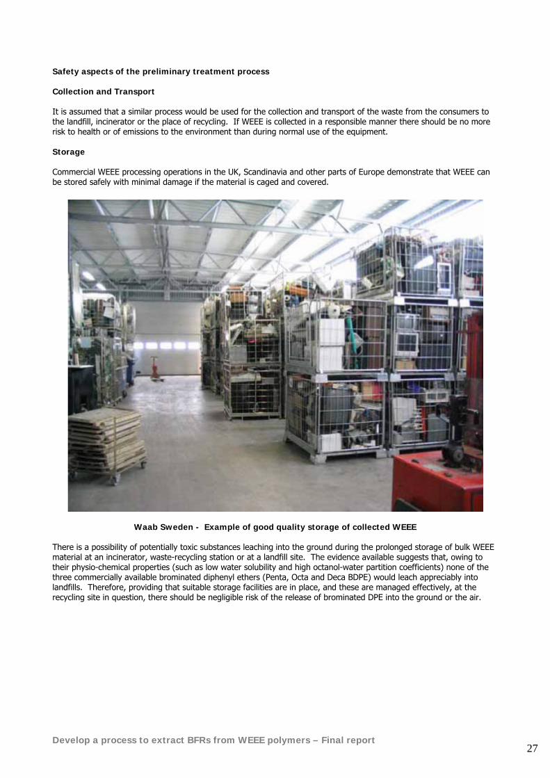
Safety aspects of the preliminary treatment process Collection and Transport It is assumed that a similar process would be used for the collection and transport of the waste from the consumers to the landfill, incinerator or the place of recycling. If WEEE is collected in a responsible manner there should be no more risk to health or of emissions to the environment than during normal use of the equipment. Storage Commercial WEEE processing operations in the UK, Scandinavia and other parts of Europe demonstrate that WEEE can be stored safely with minimal damage if the material is caged and covered.
Waab Sweden - Example of good quality storage of collected WEEE There is a possibility of potentially toxic substances leaching into the ground during the prolonged storage of bulk WEEE material at an incinerator, waste-recycling station or at a landfill site. The evidence available suggests that, owing to their physio-chemical properties (such as low water solubility and high octanol-water partition coefficients) none of the three commercially available brominated diphenyl ethers (Penta, Octa and Deca BDPE) would leach appreciably into landfills. Therefore, providing that suitable storage facilities are in place, and these are managed effectively, at the recycling site in question, there should be negligible risk of the release of brominated DPE into the ground or the air.
Develop a process to extract BFRs from WEEE polymers – Final report 28
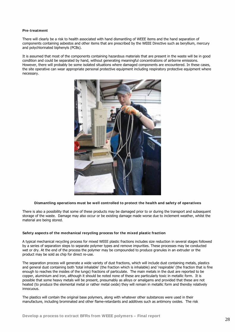
Pre-treatment There will clearly be a risk to health associated with hand dismantling of WEEE items and the hand separation of components containing asbestos and other items that are prescribed by the WEEE Directive such as beryllium, mercury and polychlorinated biphenyls (PCBs). It is assumed that most of the components containing hazardous materials that are present in the waste will be in good condition and could be separated by hand, without generating meaningful concentrations of airborne emissions. However, there will probably be some isolated situations where damaged components are encountered. In these cases, the site operative can wear appropriate personal protective equipment including respiratory protective equipment where necessary.
Dismantling operations must be well controlled to protect the health and safety of operatives There is also a possibility that some of these products may be damaged prior to or during the transport and subsequent storage of the waste. Damage may also occur or be existing damage made worse due to inclement weather, whilst the material are being stored. Safety aspects of the mechanical recycling process for the mixed plastic fraction A typical mechanical recycling process for mixed WEEE plastic fractions includes size reduction in several stages followed by a series of separation steps to separate polymer types and remove impurities. These processes may be conducted wet or dry. At the end of the process the polymer may be compounded to produce granules in an extruder or the product may be sold as chip for direct re-use. The separation process will generate a wide variety of dust fractions, which will include dust containing metals, plastics and general dust containing both ‘total inhalable’ (the fraction which is inhalable) and ‘respirable’ (the fraction that is fine enough to reaches the insides of the lungs) fractions of particulate. The main metals in the dust are reported to be copper, aluminium and iron, although it should be noted none of these are particularly toxic in metallic form. It is possible that some heavy metals will be present, presumably as alloys or amalgams and provided that these are not heated (to produce the elemental metal or rather metal oxide) they will remain in metallic form and thereby relatively innocuous. The plastics will contain the original base polymers, along with whatever other substances were used in their manufacture, including brominated and other flame-retardants and additives such as antimony oxides. The risk
Develop a process to extract BFRs from WEEE polymers – Final report 29
assessments to date have shown that, whilst there is a theoretical possibility of the leaching of certain substances, for example brominated flame-retardants from plastics, the actual risks presented by these are very low. Furthermore, the risks presented by the constituents of the brominated flame-retardants in their manufacture (and assumed to be similar during recycling) have been shown by the EU risk assessments to be low, providing that good occupational hygiene principles are adopted. It follows that the risks of exposure to hazardous substances, in particular to the constituents of the plastics, in the preliminary processing of the brown goods should remain low providing sound occupational hygiene principles are observed. The main treatment will have similar risks associated with it, although the particulate that will be handled will be finer than that at the pre-treatment stage. Many of the processes involve treatment with water, which will suppress the generation of dust. As for the pre-treatment process, the risks of exposure to hazardous substances during the processing of the waste stream should remain low, providing sound occupational hygiene principles are observed. Emissions to the environment Providing that all of the dusty processes are fitted with suitable local exhaust ventilation (LEV) and that the exhaust from such processes are controlled through adequate filtering mediums, before being exhausted to the atmosphere or being returned to the workplace, the emissions to the environment should remain negligible. Since it has been suggested that the exposures to the personnel should be low, then providing that the control measures are maintained in good working order, it follows that fugitive emissions should also remain negligible. Breakdown and transformation products There is a theoretical possibility of dibenzofurans and dibenzo-p-dioxins being formed from brominated diphenyl ethers, mainly at elevated temperatures (but also by other routes and as a result of impurities in the polymer) during the handling of brominated diphenyl ethers. However the available information for recycling of plastics indicates that there is little or no increase in the amounts of gases or vapours that are formed.
Develop a process to extract BFRs from WEEE polymers – Final report 30
7.4.2. Recovery in non-ferrous metal smelting processes This assessment is based on a description of a trial by the Swedish company Boliden and the Association of Plastics Manufacturers in Europe (APME) to process WEEE polymers in a non-ferrous metal smelting furnace31. The objective of the study was to consider the viability of adding waste PCs into the feed stream of the Zinc Fuming Furnace that is currently in routine operation at the Ronnskar plant of Boliden Minerals AB in Sweden. The plant recovers waste printed circuit boards in a Kaldo furnace. The project description concludes that the process yields high rates of metal recovery and that the plastic serves a dual purpose both as a reducing agent for the process itself and as a source of energy for the smelting. WEEE Pre-treatment The Waste electrical and electronic equipment (WEEE) used in the study was transported by train from various sources in Scandinavia and was pre-screened to remove components that were known to contain mercury. A hammer mill shredder with a magnetic iron separator was used to prepare the bulky material. After sampling, the weee material was transferred to the Ronnskar smelter. During the mechanical treatment of the waste, there was no increase in temperature above that which is normally encountered during the routine treatment of the scrap. The mix containing the PC scrap was transferred by truck to a conveyor. The conveyor loaded the scrap into the silos, which were located above the zinc-fuming furnace. The PC scrap/slag mixture and pelletised steel making dust were drawn from the silos and fed to the fuming furnace. It was reported that the operatives charged the furnace using the procedures that they normally adopted for the charging of printed circuit boards and the fuming process did not deviate from its usual performance. Safety aspects of the process Collection, transport and storage The issues will be identical to those for mechanical recycling described above, with negligible risk of emissions to environment during these stages of the process Pre-treatment There should be negligible risk to health from brominated compounds as a result of the pre-treatment process since this involved the removal of only mercury and cadmium-containing components. However there would be risk of exposure to mercury and cadmium compounds if the pre-treatment process is poorly controlled Treatment at the Ronnskar smelter The furnace will contain varying amounts of metals, notably heavy metals. Although the furnace is provided with extraction, there may be a possibility of the operatives being exposed to various metal vapours or metal oxides that will form as a result of condensation in the air and as dross on the surface of the molten metal. It was reported that air sampling was undertaken for heavy metals and dioxins during the study and that all of the results were below the actual or recommended Swedish occupational exposure limits (OELs). Analysis was also carried out for halogen-containing organic compounds: chlorinated PCDD/Fs, brominated PBDD/Fs and mixed brominated and chlorinated PBCDD/Fs. The results obtained varied significantly, and there was no correlation between the amount of PXDD/Fs and their source or age. The average PXDD/Fs content of all the samples of waste E+E plastics met the German emission regulations.
31 ‘Plastics Recovery from Waste Electrical and Electronic Equipment in Non-Ferrous Metal Processes’ Mark F, Lehner T, APME Technical Paper, 2002.
Develop a process to extract BFRs from WEEE polymers – Final report 31
Emissions to the environment It is reported that the charging area to the Kaldo furnace is encapsulated and provided with extraction to a dust control unit (bag house) and that the process gas stack is connected to a venturi scrubber. Post combustion takes place at around 1200 °C with a residence time of more than 2 seconds, in which case there is negligible risk of the formation of brominated dibenzofurans and dibenzo-p-dioxins or the chlorinated equivalents Therefore, it is unlikely that there will be meaningful emissions from the furnace.
7.4.3. Recovery in a state of the art incinerator The final treatment option considered in this section is incineration. A comprehensive study was undertaken for EBFRIP and APME at the TAMARA pilot scale municipal solid waste combustion plant in the Karlsruhe Research Centre 32. The results of the study indicate that it is technically feasible to recycle bromine in WEEE plastic containing brominated fire retardants by using modern municipal solid waste combustion plants providing they are equipped with suitable wet scrubbing systems. The TAMARA study showed that it was possible to recover commercial bromine based products such as bromine, hydrogen bromide or sodium bromide. The standard fuel used at the TAMARA plant is a mixture of 70% organic green waste and 30% refuse derived fuel (RDF). For this study the RDF was replaced by an equivalent quantity of WEEE from shredded mixed polymers, television housings and printed circuit boards. The conclusions of the study indicate that under optimum conditions, modern municipal solid waste combustion facilities that are equipped with wet scrubbing systems can be used to recover energy from polymers containing BFRs.
32 ‘Recycling of bromine from plastics containing brominated flame retardants in state-of the-art combustion facilities’ Vehlow et al, Forschungzentrum Karlsruhe, Waste Management Research, 18, pp131-140, 2000
Develop a process to extract BFRs from WEEE polymers – Final report 32
7.5. Conclusions Concerns have been raised over the environmental and human health impacts of only certain classes of brominated flame retardants. These are the polybrominated biphenyls, polybrominated diphenyl ethers (in particular, penta and octa BDE). Principal concerns are:
• Some of them have been shown to bioaccumulate in a wide range of organisms • It is believed that they may have neurotoxic effects and/or effects on human reproductive processes • Some of them may decompose to produce toxic polybrominated dioxins and furans (PBDD/F) when subjected
to elevated temperature processing It should be emphasised that many other types of additives are used today and have been used in WEEE in the past. These include a wide range of pigments and surface treatments, plasticizers, impact modifiers, fillers. The environmental and health impacts of reprocessing most of these compounds are unknown. Brominated additives have been studied in much greater detail but nobody knows the balance of risk between these materials and other additives which may be present in the polymers to be recycled. The occupational health and safety issues for the substances that will be handled by most existing WEEE recycling processes after dismantling should be well established and known. For example, there will be numerous ‘classical’ occupational exposure scenarios associated with the recovery of metal in a smelting process. From the relatively low exposures due to handling the metal to the higher exposures as a result of ‘drossing off’ the metal oxides that form on the upper surface of molten metal pots right through to the high exposures associated with maintenance work on the melting pots. It is unlikely that the introduction of WEEE to the input streams of most of these processes will cause a significant increased risk to health, for the operatives who actually carry out the work, over and above any of the existing risks that are inherent in the process in question. In many instances, the metal oxides or various gases that are produced will be more toxic than the flame-retardants that are being recovered. However, low temperature recovery or recycling processes will always have a much lower risk of emissions and of dioxin formation than high temperature solutions but they may have increased risk of other emissions such as solvents.
Develop a process to extract BFRs from WEEE polymers – Final report 33
8. EU and UK legislation applying to polymers containing BFRs
8.1. General EU legislation, standards and codes of practice Most waste management activities and strategies in the UK are now driven by EU Directives. This legislative framework can be considered in terms of:
• Horizontal legislation : Waste Framework Directive, hazardous waste, waste shipments, Environmental Information Regulations
• Waste treatment standards : Landfill Directive, Waste Incineration Directive, Environmental Impact Directive, Strategic Environmental Assessment Directive
• End-of-Life product waste stream Directives : packaging, end-of-life vehicles, WEEE, batteries, biowaste
8.1.1. The Waste Framework Directive The key Directive is the Waste Framework Directive of 1975 (75/442/EEC) as amended in 1991 (91/156/EEC). This stresses the fundamental importance of waste prevention and makes a distinction between :-
• Qualitative waste prevention and reduction – using less toxic or less hazardous resources and/or producing less toxic or less hazardous wastes (and using less in quantitative terms)
and • Quantitative waste prevention and reduction – using less resources and/or producing less wastes in tonnage
terms or in terms of resources/waste per unit of product/service The Waste Framework Directive also placed waste prevention in the context of the waste hierarchy, emphasising the move away from landfill:
Prevention
Reduction
Re-use
Recycling and composting
Incineration (or other thermal treatment) with energy recovery
Incineration (or thermal treatment) without energy recovery
Landfill
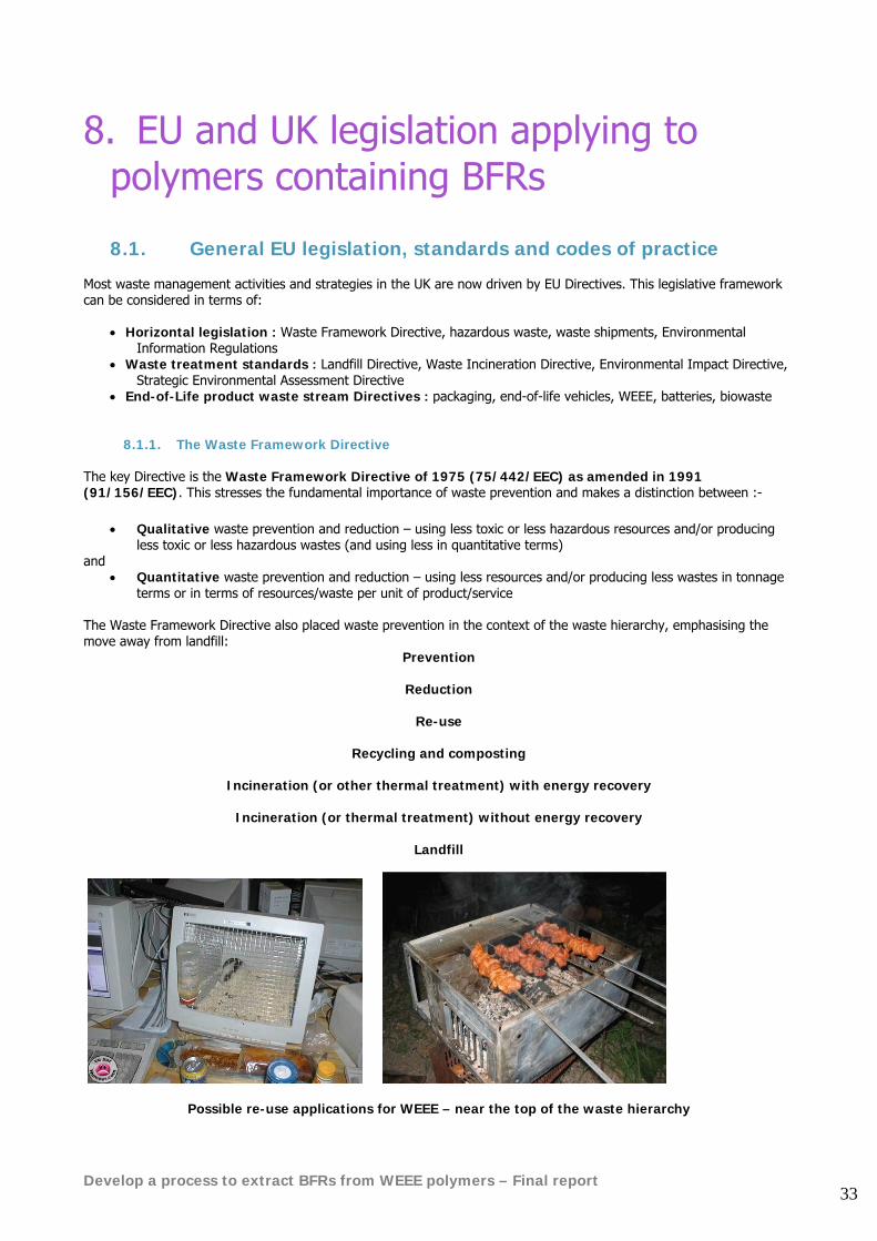
Possible re-use applications for WEEE – near the top of the waste hierarchy
Develop a process to extract BFRs from WEEE polymers – Final report 34
A key element in the Directive involves the 'disposer' in defining waste: 'waste' means any substance or object which the holder disposes of or is required to dispose of 'disposal' means:
• the collection, sorting, transport and treatment of waste as well as its storage and tipping above or below ground
• the transformation operations necessary for its re-use, recovery or recycling
Inherent in these definitions is the ‘certainty’ of waste being disposed, although inclusion of ‘transformation operations’ under the heading of disposal creates complications for re-use, recovery and recycling. This interpretation has led to problems as to when (if) waste ceases to be waste if it is recycled or recovered. It is possible that amendments will be made to the Waste Framework Directive definitions as part of the Thematic Strategies published in 2005 (see below). A number of important draft EU Communications33 were circulated for consultation in October 2005, and published in December 2005. Alongside the publication of these documents it became apparent that the EU Commission was planning to simplify existing waste legislation, by re-writing and combining 18 EU Directives and six regulations covering the sector.34 In January 2006, a ‘composite’ report was published titled ‘EU Waste Policy : The Story Behind the Strategy’.35 This ‘overview’ stresses the link between the Sixth Environment Action Programme (6th EAP, 2002-2012) and the development of the Thematic Strategy on Waste Prevention and Recycling, given the priorities of climate change, health and quality of life, natural resources and waste. The review comments on the generally negative view of waste and the need to move towards a more flexible regulatory framework promoting a recycling society – “… a society that avoids wastage and uses the resources that are found in waste”. Early EU Directives did not specify the environmental emission parameters for various waste management options. However, more recent Directives address some of these issues, e.g. the Landfill Directive which specifies methane emissions and the Waste Incineration Directive which specifies dioxins. Four outstanding issues were identified:
• past legislation addressed visible, and often acute, environmental problems. New policies need to be based on wider information that is currently not available, but still focussing on environmental protection
• the link between waste generation and economic growth • the potential to increase use of the resources embedded in waste, either for recycling or for energy recovery –
thus reducing demand for primary resources • the need to re-consider the role of trans-frontier movements for recycling
An emphasis is placed on the ‘triangular’ links, first put forward in 2003, between the Thematic Strategy on Sustainable Use of Resources, Integrated Product Policy and the Thematic Strategy on the Prevention and Recycling of Waste, with the latter being the key driver. These have been extensively discussed by stakeholder/focus groups, workshops and meetings of experts. A key issue raised is whether weight or volume indicators are the most appropriate indicators of the environmental burdens of waste, in the context of waste prevention. The waste hierarchy is supported, but for specific waste streams energy recovery may be environmentally preferable to recycling. For example the document argues that incineration may be the best option for. mixed contaminated plastics. Given the existing end-of-life product Directives, improving recycling markets is potentially more important than promoting material-based recycling, but this will be reviewed in five years time.
33 This is a personal summary of key points. Readers are advised to refer to the actual draft Documents. 34 http://europa.eu.int/comm/environment/waste/strategy.htm 35 http://europa.eu.int/comm/environment/waste/pdf/story_book.pdf
Develop a process to extract BFRs from WEEE polymers – Final report 35
Reference is made to the need for:
• streamlining waste legislation • clarifying the continued role of the waste hierarchy, including waste prevention and definitions of recovery and
disposal, and the definition of waste • common EU standards and an EU recycling market • an overall eco-efficient recycling and recovery policies covering all waste materials (existing Directives based
on waste-streams cover only 7% of total waste volumes) • a good knowledge base informs waste policy
A timetable of ‘next steps’ is provided leading to 2008 and the entry into force of the revised Waste Framework Directive, together with other related measures and activities, with the Waste Strategy to be reviewed in 2010. The position of the European Commission was clarified further during 2005 by the following proposal: Communication from the Commission (2005). Proposal for a Directive of the European Parliament and of the Council on waste. Brussels, 21.12.2005, COM(2005) 667 Final This is intended to revise and optimise the provisions of the Waste Framework Directive 75/442/EC (as amended by 91/156/EEC), and is expected to come into force in 2008:
• “This Directive lays down measures with a view to reducing the overall environmental impacts, related to the use of resources, of the generation and management of waste.
• For the same purposes, it also makes provision whereby the Member States are to take measures, as a matter of priority, for the prevention or reduction of waste production and its harmfulness and, secondly, for the recovery of waste by means of re-use, recycling and other recovery operations”.
With the main amendments being:
• the introduction of an environmental objective • clarification of the notions of recovery and disposal • clarification of the conditions for the mixing of hazardous waste • introduction of a procedure to clarify when a waste ceases to be a waste for selected waste streams, with
compost and aggregates being the first to clarified (by 2008) Article 3 keeps the same definition of waste:
• ‘waste’ means any substance or object which the holder discards or intends or is required to discard But adds a new definition of recycling:
• ‘recycling’ means the recovery of waste into products, materials or substances whether for the original or other purposes. It does not include energy recovery.
Article 5 in Chapter II is titled ‘recovery’:
• Member States shall take the necessary measures to ensure that all waste undergoes operations that result in it serving a useful purpose in replacing, whether in the plant or in the wider economy, other resources which would have been used to fulfil that function, or in it being prepared for such a use.
Article 11 on Secondary products, materials and substances:
• With a view to determining whether it is appropriate to deem certain wastes to have ceased being waste, to have completed a re-use, recycling or recovery operation, and to reclassify that waste as secondary products, materials or substances, the Commission shall assess whether the following conditions are met :-
o reclassification would not lead to overall negative environmental impacts o a market exists for such a secondary product, material or substance
Develop a process to extract BFRs from WEEE polymers – Final report 36
In this context, a significant amendment to the definition of Recovery in Annex II (replacing Annex IIB) is provided: R1 Use principally as a fuel or other means to generate energy. This includes incineration facilities dedicated to the processing of municipal solid waste only where their energy efficiency is equal to or above :-
o 0.60 for installations in operation and permitted in accordance with applicable Community legislation before 1 January 2009
o 0.65 for installations in operation and permitted in accordance with applicable Community legislation after 31 December 2008
Energy efficiency = ((Ep- (Ef + Ei)) 0.97 x (Ew + Ef) Ep means annual energy exported calculated with energy in the form of electricity multiplied by 2.6 (GJ/y) Ef means annual energy input to the system from fuels contributing to the production of steam (GJ/y) Ew means annual energy contained in the treated waste (GJ/y) Ei means annual energy imported excluding Ew and Ef (GJ/y) 0.97 is a factor accounting for energy losses due to bottom ash and radiation
8.1.2. The Landfill Directive The Council Directive (99/31/EC) on the landfill of waste is seen as possibly the most important Directive likely to affect the UK, with bans on tyres and other materials to landfill, an end to co-disposal (landfilling of hazardous and non-hazardous wastes in the same landfill) and targets for the diversion of biodegradable municipal wastes from landfill. The Directive also sets down a classification of landfill sites:
• landfill for hazardous waste (including relevant hazardous components of WEEE)
• landfill for non-hazardous waste
• landfill for inert waste In February 2004, the European Parliament called for a ban on landfilling of all waste by 2025 as part of the forthcoming EU Thematic Strategy on the Prevention and recycling of Waste (see below):
• ban on landfilling of untreated biodegradable waste by 2010
• ban on landfilling of recyclables by 2015
• ban on landfilling of recoverable waste by 2020
• ban on landfilling all residual waste by 2025 – except where ‘unavoidable’ or hazardous At the same time, the resolution points to the ‘importance of energy recovery for sustainable waste management’ in meeting the landfill ban.
Develop a process to extract BFRs from WEEE polymers – Final report 37
8.1.3. The Waste Incineration Directive The Council Directive (00/76/EC) on the incineration of waste (known as the Waste Incineration Directive or ‘WID’) repeals the 1989 Municipal Waste Incineration Directive (89/429/EEC and 89/369/EEC) and the Hazardous Waste Incineration Directive (94/67/EC) with effect from 28th December 2005. The Waste Incineration (England and Wales) Regulations 2002 (SI 2002 No. 2980) came into force on 28th December 2002 and Edition 2 of Guidance on Directive 00/76/EC on the incineration of waste was published in August 2004. This Directive applies immediately to all new incinerators and will apply to existing installations with effect from 28th December 2005, implementation in the UK being carried out mainly under the existing Pollution Prevention and Control (PPC) regime:
• regulation of larger incinerators and co-incinerator as Part A(1) activities by the Environment Agency • regulation of smaller Part A(2) or Part B incinerators by Local Authorities
8.1.4. The RoHS Directive Restriction of the Use of Certain Hazardous Substances in Electrical and Electronic Equipment (RoHS) (02/95/EC) (The ‘RoHS Directive’) is a daughter directive of the Waste Framework directive. It aims to improve qualitative waste prevention in waste electrical and electronic equipment (WEEE). The RoHS directive requires that from 1st July 2006 new E+E equipment put on the market does not contain:
• Lead • Mercury • Cadmium • hexavalent chromium • polybrominated biphenyls (PBBs) • polybrominated diphenylethers (PBDEs)
Penta and Octa diphenylether are already phased out (in concentrations above 0.1% by mass) by the Marketing and Use Directive of 15 August 2004 (2003/11/EC). However Deca BDE is still widely used in electronic equipment and the bromine industry has resisted its inclusion in the RoHS list due to the positive outcome of the EU environmental impact risk assessment for Deca BDE. The RoHS Directive gives producers a clear guarantee that no individual EU Member States will be able to introduce separate bans or restrictions on any other substance than those specified in the RoHS Directive. A review of the RoHS Directive to potentially integrate new substances to be phased out will only take place from 2005. This Directive has major implications for manufacturers (and component suppliers), importers, brand owners and potentially even retailers who must be able to demonstrate that their products are RoHS compliant and do not exceed threshold limits for toxic substances. Sellers of refurbished products will also be affected. In Europe in April 2005, the Technical Adaptation Committee (TAC) took a vote on the draft Commission Decision amending the RoHS Annex to include two further exemptions - deca BDE in polymeric applications and lead in lead-bronze bearing shells and bushes. On 15th and 21st October 2005, exemptions to the RoHS Directive were published as Commission Decisions in the Official Journal and became law. Applications that will be exempt include the use of lead in optical and filter glass and electronic ceramic parts, and cadmium in electrical contacts.36 The RoHS Directive came into force on 1st July 2006. In a note circulated in June 2006, the European Commission advised that the exemption for deca-BDE in polymeric applications does not apply, as commercial formulations of deca contain nona-BDE which was/is covered by the RoHS ban.
36 http://www.dti.gov.uk/sustainability/weee/RoHS_Exemptions_October2005.pdf
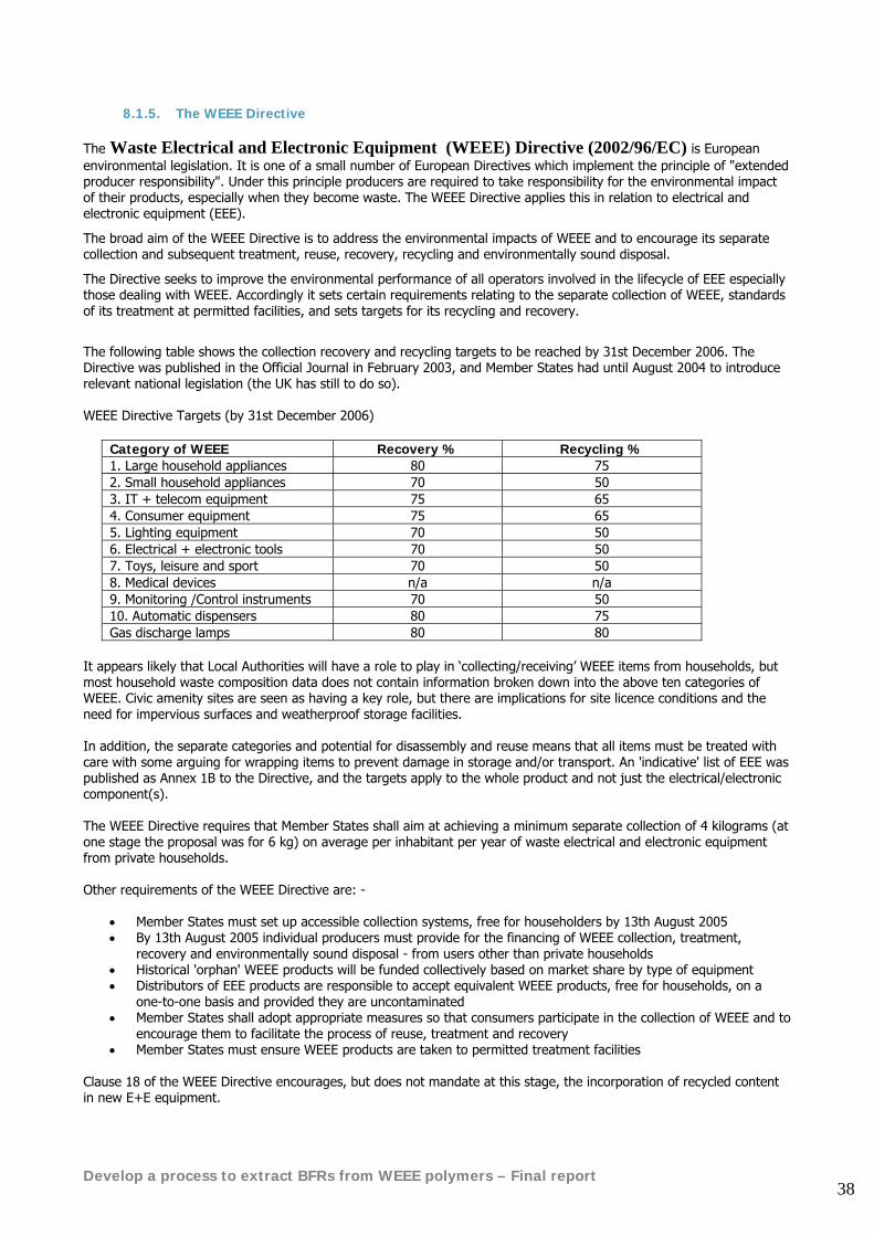
Develop a process to extract BFRs from WEEE polymers – Final report 38
8.1.5. The WEEE Directive The Waste Electrical and Electronic Equipment (WEEE) Directive (2002/96/EC) is European environmental legislation. It is one of a small number of European Directives which implement the principle of "extended producer responsibility". Under this principle producers are required to take responsibility for the environmental impact of their products, especially when they become waste. The WEEE Directive applies this in relation to electrical and electronic equipment (EEE).
The broad aim of the WEEE Directive is to address the environmental impacts of WEEE and to encourage its separate collection and subsequent treatment, reuse, recovery, recycling and environmentally sound disposal.
The Directive seeks to improve the environmental performance of all operators involved in the lifecycle of EEE especially those dealing with WEEE. Accordingly it sets certain requirements relating to the separate collection of WEEE, standards of its treatment at permitted facilities, and sets targets for its recycling and recovery.
The following table shows the collection recovery and recycling targets to be reached by 31st December 2006. The Directive was published in the Official Journal in February 2003, and Member States had until August 2004 to introduce relevant national legislation (the UK has still to do so). WEEE Directive Targets (by 31st December 2006)
Category of WEEE Recovery % Recycling % 1. Large household appliances 80 75 2. Small household appliances 70 50 3. IT + telecom equipment 75 65 4. Consumer equipment 75 65 5. Lighting equipment 70 50 6. Electrical + electronic tools 70 50 7. Toys, leisure and sport 70 50 8. Medical devices n/a n/a 9. Monitoring /Control instruments 70 50 10. Automatic dispensers 80 75 Gas discharge lamps 80 80
It appears likely that Local Authorities will have a role to play in ‘collecting/receiving’ WEEE items from households, but most household waste composition data does not contain information broken down into the above ten categories of WEEE. Civic amenity sites are seen as having a key role, but there are implications for site licence conditions and the need for impervious surfaces and weatherproof storage facilities. In addition, the separate categories and potential for disassembly and reuse means that all items must be treated with care with some arguing for wrapping items to prevent damage in storage and/or transport. An 'indicative' list of EEE was published as Annex 1B to the Directive, and the targets apply to the whole product and not just the electrical/electronic component(s). The WEEE Directive requires that Member States shall aim at achieving a minimum separate collection of 4 kilograms (at one stage the proposal was for 6 kg) on average per inhabitant per year of waste electrical and electronic equipment from private households. Other requirements of the WEEE Directive are: -
• Member States must set up accessible collection systems, free for householders by 13th August 2005 • By 13th August 2005 individual producers must provide for the financing of WEEE collection, treatment,
recovery and environmentally sound disposal - from users other than private households • Historical 'orphan' WEEE products will be funded collectively based on market share by type of equipment • Distributors of EEE products are responsible to accept equivalent WEEE products, free for households, on a
one-to-one basis and provided they are uncontaminated • Member States shall adopt appropriate measures so that consumers participate in the collection of WEEE and to
encourage them to facilitate the process of reuse, treatment and recovery • Member States must ensure WEEE products are taken to permitted treatment facilities
Clause 18 of the WEEE Directive encourages, but does not mandate at this stage, the incorporation of recycled content in new E+E equipment.
Develop a process to extract BFRs from WEEE polymers – Final report 39
Finally Annex 2 of the WEEE Directive requires separate treatment for the following components of recovered WEEE: • Capacitors containing PCBs, • Liquid crystal displays over 150sq cm • Mercury switches • Asbestos (found for example in some older domestic irons) • Polymers containing brominated flame retardants
The requirements of Annex 2 effectively mean that shredding of unsorted WEEE is a process that cannot comply with the WEEE Directive. Some segregation or sorting and dismantling of the feed stream will always be required to ensure that the items listed above are separately treated. The driving force for this project is the requirement in Annex 2 of the WEEE directive that polymers containing brominated flame retardants are treated separately. The UK is late in implementing the timetable requirements of the WEEE Directive. Implementation in the UK is currently expected by mid 2007.37
8.1.6. Likely future developments The general trend of EU environmental legislation is towards tougher targets and tighter regulations. In the short term the most immediate impact for the E&E sector will come from the review/revision of the WEEE Directive that is due in 2006. It is likely that reuse targets may be introduced to complement increased recycling and recovery targets. As foreseen in the EU 6th Environmental Action Programme, the longer term development of EU policies will be in the context of seven Thematic Strategies, aiming for a more integrated and holistic approach to policy development. The two Thematic Strategies of direct relevant for WEEE and BFRs are:
• COM 301: ‘Prevention and Recycling of Waste’ • COM 572 ‘Sustainable Use of Natural Resources’.
Latest thinking on these strategies is summarised below:
8.1.6.1. Prevention and Recycling of Waste Strategy (COM(2003) 301 final) Communication from the Commission (2005). Taking sustainable use of resources forward: A Thematic Strategy on the prevention and recycling of waste. This communication aims to reduce the overall negative environmental impact of resource use through:
• a renewed emphasis on full implementation of existing legislation • simplification and modernisation of existing legislation • introduction of life-cycle thinking into waste policy (cradle to grave) • promotion of more ambitious waste prevention policies • more and better knowledge and information • development of common reference minimum standards for recycling, and prevent the threat of ‘eco-dumping’ • further elaboration of the EU’s recycling policy, to allow the adoption of environmental criteria for specific waste
flows in order to specify when they no longer fall under the scope of waste legislation, but rather are to be considered as products
• less waste to landfill • more compost and energy recovered from waste • more and better recycling
The document states: “As waste moves away from landfill it will move into a variety of options higher up the waste hierarchy, all of which will be better for the environment. An important part of this picture is the conversion of waste into energy and into compost, a process which is currently under-used in a number of Member States
37 http://www.dti.gov.uk/sustainability/weee/Deca_BDE_Decision_October2005.pdf
Develop a process to extract BFRs from WEEE polymers – Final report 40
The development of clean and efficient incinerators and co-incinerators, meeting the high standards set out in the Waste Incineration Directive will mean that for a number of waste flows, incineration with energy recovery will be the best option. This will help the EU meet its targets under the Directive on the promotion of electricity from renewable energy sources.” With further reference to energy from waste the document states: “the definitions contained in present legislation as interpreted by the European Court of Justice do not promote best environmental practice, for example as regards recovering energy from waste in municipal incinerators.” “…an amendment to the Waste Framework Directive which will base the definition of recovery on the notion of substitution of resources in the economy as opposed to the specific plant.” “A first example of this approach is the use of efficiency thresholds to classify waste treatment in municipal incinerators either as recovery or as disposal. Current jurisprudence of the European Court of Justice classifies the overwhelming majority of municipal incinerators as disposal facilities. This classification may have negative implications, leading to a degradation of the environment. For example, incineration with energy recovery is usually considered as a means of diverting biodegradable municipal waste from landfills. However, there are concerns that if incineration is defined in the same category as landfilling, some local authorities may be tempted to choose the cheapest option (landfilling), which will in turn degrade the environment. Additionally, municipal incinerators with high energy efficiency are negatively discriminated in comparison with some co-incineration operations that have similar energy efficiencies but less stringent emission controls.” “A recovery definition that takes into account that energy produced by a given municipal incinerator substitutes the use of resources in other energy producing plants will better reflect the environmental benefits of incineration. However, the energy efficiency of municipal incinerators can vary dramatically. At low energy efficiencies incinerators may not be more favourable than landfill. At high energy efficiency incineration may be as favourable as mechanical recycling or bio-treatment of certain waste flows.” Reference is then made to the proposed change to the definition of R1 in Annex IIB (see separately). “Overlaps between the permit procedures set-up in the Waste Framework Directive and the Integrated Pollution Prevention and Control Directive will be removed by indicating that where an IPPC permit is held, an additional waste permit is not necessary.” Proposed guidelines on the issue of when by-products should or should not be considered as waste, based on the jurisprudence of the European Court of Justice, are expected to be published in 2006.
8.1.6.2. Sustainable Use of Natural Resources Strategy A further influential EU document is the strategy for use of natural resources: Communication from the Commission (2005). Thematic Strategy on the sustainable use of natural resources.
• the overall objective is to reduce the negative environmental impacts generated by the use of natural resources in a growing economy, a concept referred as de-coupling and involving life cycle assessment of impacts from cradle to grave on an EU and global scale as necessary
• to include improved knowledge (including an ‘information hub’) • tools to monitor and report progress : efficiency and productivity in use of natural resources and energy,
resource-specific environmental impacts, eco-efficiency, and overall indicator of ecological stress of resource use
• foster the application of strategic approaches in Member States, with sector action plans for specific economic sectors
• raise awareness • a long term horizon of 25 years is proposed
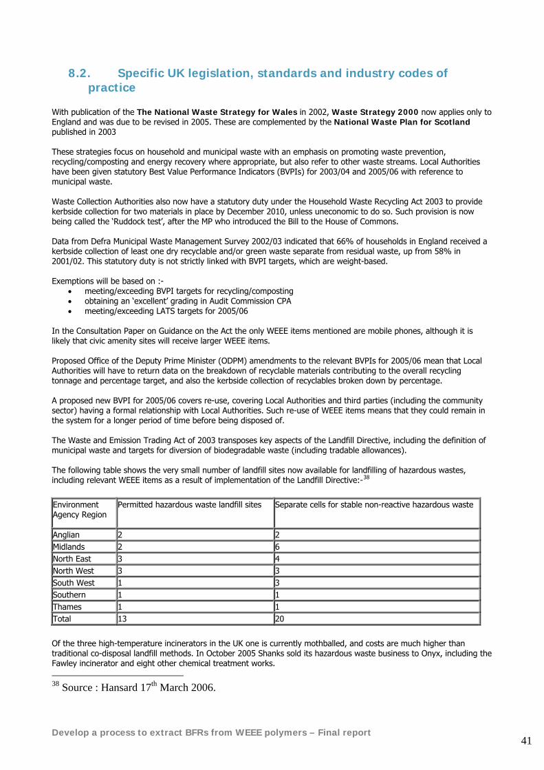
Develop a process to extract BFRs from WEEE polymers – Final report 41
8.2. Specific UK legislation, standards and industry codes of practice
With publication of the The National Waste Strategy for Wales in 2002, Waste Strategy 2000 now applies only to England and was due to be revised in 2005. These are complemented by the National Waste Plan for Scotland published in 2003 These strategies focus on household and municipal waste with an emphasis on promoting waste prevention, recycling/composting and energy recovery where appropriate, but also refer to other waste streams. Local Authorities have been given statutory Best Value Performance Indicators (BVPIs) for 2003/04 and 2005/06 with reference to municipal waste. Waste Collection Authorities also now have a statutory duty under the Household Waste Recycling Act 2003 to provide kerbside collection for two materials in place by December 2010, unless uneconomic to do so. Such provision is now being called the ‘Ruddock test’, after the MP who introduced the Bill to the House of Commons. Data from Defra Municipal Waste Management Survey 2002/03 indicated that 66% of households in England received a kerbside collection of least one dry recyclable and/or green waste separate from residual waste, up from 58% in 2001/02. This statutory duty is not strictly linked with BVPI targets, which are weight-based. Exemptions will be based on :-
• meeting/exceeding BVPI targets for recycling/composting • obtaining an ‘excellent’ grading in Audit Commission CPA • meeting/exceeding LATS targets for 2005/06
In the Consultation Paper on Guidance on the Act the only WEEE items mentioned are mobile phones, although it is likely that civic amenity sites will receive larger WEEE items. Proposed Office of the Deputy Prime Minister (ODPM) amendments to the relevant BVPIs for 2005/06 mean that Local Authorities will have to return data on the breakdown of recyclable materials contributing to the overall recycling tonnage and percentage target, and also the kerbside collection of recyclables broken down by percentage. A proposed new BVPI for 2005/06 covers re-use, covering Local Authorities and third parties (including the community sector) having a formal relationship with Local Authorities. Such re-use of WEEE items means that they could remain in the system for a longer period of time before being disposed of. The Waste and Emission Trading Act of 2003 transposes key aspects of the Landfill Directive, including the definition of municipal waste and targets for diversion of biodegradable waste (including tradable allowances). The following table shows the very small number of landfill sites now available for landfilling of hazardous wastes, including relevant WEEE items as a result of implementation of the Landfill Directive:-38 Environment Agency Region
Permitted hazardous waste landfill sites Separate cells for stable non-reactive hazardous waste
Anglian 2 2 Midlands 2 6 North East 3 4 North West 3 3 South West 1 3 Southern 1 1 Thames 1 1 Total 13 20
Of the three high-temperature incinerators in the UK one is currently mothballed, and costs are much higher than traditional co-disposal landfill methods. In October 2005 Shanks sold its hazardous waste business to Onyx, including the Fawley incinerator and eight other chemical treatment works. 38 Source : Hansard 17th March 2006.
Develop a process to extract BFRs from WEEE polymers – Final report 42
In July 2005 Defra issued new guidance indicating that, despite the above comments, mixed municipal waste is not hazardous and “… items of WEEE separated out at the civic amenity/household wastes sites or during bulky household collection” should not be treated as hazardous waste. However, “Local Authorities should ensure that they are complying with Duty of Care and know where their municipal waste, including any separately collected WEEE, is going for recovery or disposal”. In addition, not all WEEE is necessarily waste and items which are separated out and are reusable or need minor repair are probably not waste. As of 16th July 2005 civic amenity sites and waste transfer stations accepting separate collections of household hazardous waste, such as TVs and batteries, need to register as waste producers under hazardous waste regulations. Originally, the WEEE Directive was to be transposed by 13th August 2005, and changes to the above may occur when the WEEE Directive is implemented in 2006. This ‘mis-match’ of implementation has caused a variety of problems for producers and Local Authorities. In April 2006 concerns were expressed by the Environment Agency about using shredding equipment to treat WEEE, which may release hazardous heavy metals and compounds. Annex II of the Directive covers the removal of such hazardous materials before shredding. Draft Guidance for Waste Collection Authorities on the Household Waste Recycling Act 2003 issued in July 2004 has a table of ‘commonly collected materials’, in the context of the Government setting a statutory target for Local Authorities in England to collect at least two recyclables from the kerbside by 2010 :-
• plastics counts as one type of recyclable waste, however many types of polymers are collected • mobile phones count as one type of recyclable waste even though different components can be treated
differently • one off collections of bulky items (could include WEEE ?) will not count as a type of recyclable waste
England – Waste Strategy 2006 Consultation New targets to recycle up to half of all household waste is just one of a number of proposals in a major consultation on the Government's strategy for waste in England. Launching the consultation, Minister for Local Environment Quality, Ben Bradshaw said "We've made some really positive progress since 2000: recycling and composting of household waste has doubled, nearly 50 per cent of packaging waste is being recycled and less waste is being sent to landfill. We need to put more effort into producing less waste in the first place, before considering how to make more use of the waste which is left by reusing, recycling, composting or using it as a fuel". In a YouGov survey for Defra, only 3% of people always think about how they are going to get rid of the everyday items they buy when they no longer need or want it, half of people admitted that it never crosses their minds. Indeed, many people thought they were paying more for waste collection, treatment and disposal than they actually were. Most people (38%) think that it currently costs local authorities £10 per week to collect and deal with their household waste, in fact it is on average just £2 per household. Among the measures being proposed are:
• greater focus on producing less waste in the first place by developing a greater emphasis on eco-design • increased engagement with businesses and householders on waste prevention • more agreements with businesses to take greater responsibility for their products at the end of their life • new recycling and composting targets for household waste are proposed: 40% in 2010, 45% by 2015, 50% by
2020 • recovering more resources from businesses waste with new targets for a reduction in the proportion of
commercial and industrial waste landfilled, more help for small businesses and a more joined up approach in managing waste from different sources facilitated by local authorities and regional bodies
• making proper use of new investment to recover energy from waste as an alternative to landfill, but not at the expense of practical waste prevention and recycling by seeing a more modest growth than original estimates. It is proposed to set a target for 67% recovery of waste by 2015 by recycling, composting, energy from waste (incineration, pyrolysis and gasification) and digestion with at least 45% composting and recycling.
Develop a process to extract BFRs from WEEE polymers – Final report 43
The consultation paper Review of England's Waste Strategy A Consultation Document February 2006 and accompanying Regulatory Impact Assessment and Environment Report are available from Defra's website.3940 Deadline for comments was 9 May 2006. Subject to the outcome of this consultation, the Government intends to publish a revised waste strategy for England later in 2006, setting out Government's vision and strategic direction on waste for the next 20 years, as well as the policies and actions which will be necessary to deliver the new strategy. Key proposals in summary:
• increased national targets for recycling and composting of household waste (40% by 2010 and 50% by 2020) • setting targets for landfilling commercial and industrial waste • simplifying the regulatory system • extending producer responsibility to cut waste and increase recycling • keeping the pricing framework under review • promoting behaviour changes by business and the public through information, advice and awareness raising • greater Government leadership by example in dealing with its own waste and its procurement operations • strategies and programmes to improve the evidence base to help us to target our policies more effectively • prioritising products with the most significant waste impacts • extending product stewardship by producers and retailers, and reducing waste impacts through eco-design • promoting re-use and remanufacture • engaging with businesses (including SMEs) to stimulate resource efficiency • providing advice to consumers (business and the public) on environmental impacts of products • targets for Local Authorities to reduce and recycle household waste • piloting more recycling services for small businesses • encouraging energy recovery but not at the expense of practicable waste prevention, recycling and composting • placing further restrictions on use of landfill in the longer term • an over-arching procurement strategy and increased effort on market shaping, to help local authorities make
the investment needed. Continuing to develop markets for recycled materials including further standards for such materials which will allow lighter regulation
• new management plan for waste imports and exports. • arrangements for better collection and management of household hazardous waste • establish a Sustainable Waste Programme Board to drive delivery of the strategy and ensure coherence of
waste policies. o Strengthen regional working including better partnership between local authorities at the regional level in planning for waste
• a wider strategic role for local authorities (in partnerships) to facilitate more integrated management of different waste streams
• improve the interaction of producers and compliance organisations with local authorities to deliver EU and national targets
• help the voluntary and community sector make its contribution particularly through innovation and engaging people.
39 http://www.defra.gov.uk/corporate/consult/wastestratreview/review-consult.pdf 40 www.defra.gov.uk/corporate/consult/wastestratreview/index.htm
Develop a process to extract BFRs from WEEE polymers – Final report 44
8.3. UK interpretation and implementation of EU WEEE regulations In terms of WEEE, the UK has progressed through 3 stages of consultation :-
• 31st March – 30th May 2003, Discussion Paper setting out all the implementation options
• 26th November – 1st March 2004, Consultation Paper set out preferred options
• 30th July – 29th October 2004 , Draft Regulations and Guidance The UK consultations stalled during early 2005 when it became clear that the UK system would not be in place in time for implementation by the summer. In mid 2005 the DTI announced that implementation would be deferred until end 2006 at the earliest while the consultation process was restarted. The new consultation process, with a combined DTI/DEFRA team commenced in the autumn of 2005 By April 2006 initial indications of the likely structure of the WEEE Directive implementation system in the UK were published by DTI.41 Another UK WEEE Consultation was published in late July 2006, seeking views of businesses, manufacturers, retailers, producers and enforcement authorities on draft regulations implementing Directives 2002/96/EC and 2003/108/EC of the European Parliament relating to waste electrical and electronic equipment. This consultation does not seek views on the provisions of the Directive itself but on the UK's proposed interpretation of it.42
Malcolm Wicks, Energy Minister has given business a clear timetable for implementing the EC Directive on Waste Electrical and Electronic Equipment (WEEE).
Launching the Government's consultation on the key proposals to be introduced from 1 July 2007, Mr Wicks said: "Electrical equipment is the fastest growing category of rubbish across the European Union, with around 20kg per person produced every year, and the UK alone is now generating around 1m tonnes of the stuff every year. These proposals are good for consumers, good for responsible producers and good for our environment. By providing a way of ensuring that electronic waste no longer has to go to landfills, manufacturers and importers will have the responsibility to ensure that they plan for both their new and existing products to be recycled rather than dumped".
The consultation marks the beginning of the final phase of the Government's process for implementing the WEEE Directive. The proposals outlined in the consultation follow on from a review of our implementation proposals last December and have been developed through extensive consultation with key stakeholders to ensure that they are workable.
The key proposals are:
• a national Distributor Takeback Scheme which will establish a network of Designated Collection Facilities enabling consumers to return their used items for recycling or reuse
• obligatory registration for producers through approved compliance schemes
• Authorised Treatment Facilities, which will process WEEE and provide evidence to producers on the amount of WEEE received for treatment
• accredited reprocessing/recycling facilities who will provide evidence of reprocessing to producers
• an end-of-year settlement to ensure producers are able to meet their obligations via an "Exchange” system
• a voluntary approach for producers to show the cost of handling historical WEEE.
• implementation with effect from 1st July 2007
More detail of the latest consultation is provided in Appendix 1
41 http://www.dti.gov.uk/innovation/sustainability/weee/page30269.html 42 WEEE consultation: Part I. Draft implementation of directives 2002/96/EC and 203/108/EC on waste electrical and electronic equipment
http://reporting.dti.gov.uk/cgi-bin/rr.cgi/http://www.dti.gov.uk/files/file32449.pdf
Develop a process to extract BFRs from WEEE polymers – Final report 45
8.4. Country-specific legislation which may affect design criteria across the EU
The electrical and electronics industry is largely multinational in nature, with much of the manufacturing taking place outside the EU. This means that E+E equipment is often designed and manufactured for use right across the EU or even world-wide. As a result product designers have to ensure that the equipment they are specifying will conform not only to Pan-European legislation but also to any local variations to that legislation. Certain aspects of German and Scandinavian environmental legislation affect the use of polymers containing flame retardants as follows:
8.4.1. Germany Germany has passed its own country-specific legislation known as the ‘Dioxin chemical Banning Ordinance’ of 199643 as a result of pressure from environmental campaigners. It is the only law of this type in Europe. This law restricts the amount of specified dioxins, furans and their brominated equivalents that may be present in new items placed on the market in Germany to below 1ppb TEQ for certain classes of dioxin compounds and 5ppb TEQfor a broader range of dioxin and furan compounds. Recent research in Germany44 has demonstrated that it is difficult to achieve these targets when Deca and octa BDE, TBPE and certain other types of ‘matrix’ type brominated flame retardants are used as flame retardants but they may be achieved when ‘backbone’ type flame retardants such as TBBPA or brominated epoxy oligomer are used45.
8.4.2. Scandinavia In some Scandinavian countries such as in Denmark, separate treatment of all flame retardent plastics will be required in future. This law will not directly affect the objectives of this project as we already assume that separation of polymers containing brominated flame retardants will be required
8.5. Use of recycled polymers containing brominated flame retardants in applications outside E+E equipment
The WEEE Directive and the RoHS Directive only place restrictions on use of polymers containing brominated flame retardants in E+E equipment and the WEEE Directive only requires separate treatment for recycled polymers containing BFRS that arise from WEEE. The key directive that affects the use of polymers containing brominated flame retardants in applications outside E+E equipment is the ‘Penta’ Directive. 2003/11/EC (Directive of the European Parliament and of the council of 6th February 2003 amending for the 24th time Council Directive 76/769/EEC relating to restrictions on the marketing and use of certain dangerous substances and preparations) The Penta Directive states that with effect from 15th August 2004 pentabromodiphenyl ether and octabromodiphenyl ether (penta and octa BDE) may not be placed on the market or used as a substance or of preparations in concentrations higher than 0.1% by mass, and articles may not be placed on the market if they, or flame-retarded parts thereof, contain these substances in concentrations higher than 0.1% by mass. Statutory Instrument 2004 No. 371 implemented this action in the UK as The Controls On Pentabromodiphenyl Ether And Octabromodiphenyl Ether Regulations 2004. Proposals to include penta and Octa BDE in the Stockholm Convention on Persistent Organic Pollutants were proposed by the European Commission in August 2004, but opposed by the European Brominated Flame Retardent Industry Panel (EBFRIP).
43 Chemikalienverbotsverordnung, Bundegesetzblatt (1996) 818 44 ‘Polymers in WEEE contain PBDD/F in the ppb-Range’, Schlummer M, Brandl F, Maurer A, Gruber L, Wolz G, Fraunhofer IVV, Organohalogen Compounds, V66, 2004 45 ‘Comparison of the recyclability of flame-retarded plastics’, Imai T, Hamm S, Rothenbacher K, Technopolymer and BSEF, Environmental Science and Technology, Am Chem Soc, 2004
Develop a process to extract BFRs from WEEE polymers – Final report 46
With regard to Deca-BDE, the final EU risk assessment for Deca-BDE is yet not officially published. The only part that is officially published is the environmental risk assessment46. The human health part was finalised in October 2005 and is expected to be published on the European Chemicals Bureau website in early 2006. At a meeting on 15th October 2005, the EU Member States and the European Commission discussed the Deca-BDE exemption from the RoHs Directive. At this meeting it was decided to exempt Deca BDE from the requirements of the RoHS Directive. According to this note, "the UK said that it believed the RoHs ban on Deca-BDE was both no longer appropriate and incompatible with the other [EU Risk Assessment] legislation. A Commission official from DG Enterprise added that the risk assessment was now officially completed and that the agreed programmes were aimed at addressing any remaining concerns. Whilst some TAC members supported the UK and DG Enterprise position, two disagreed and said that the precautionary principle should be applied since there still were some unknown concerns". In March 2006 the European Commission announced a period of consultation over possible exemptions of an annex to Directive 2002/95/EC of the European Parliament and of the Council on the restriction of the use of certain hazardous substances (ROHS) in electrical and electronic equipment. Article 4(1) of Directive 2002/95/EC on the restriction of the use of certain hazardous substances in electrical and electronic equipment (1) provides 'that from 1 July 2006, new electrical and electronic equipment put on the market does not contain lead, mercury, cadmium, hexavalent chromium, PBB or PBDE.' The annex to the Directive lists a limited number of applications of lead, mercury, cadmium and hexavalent chromium, which are exempted from the requirements of Article 4(1). According to Article 5 (2) of Directive 2002/95/EC the Commission is required to consult the relevant stakeholders before amending the annex. The results of this consultation will be forwarded to the Technical Adaptation Committee of the Directive 2002/95/EC and the Commission services will provide an account of the information received. Although the Commission will analyse the results of this stakeholder consultation carefully, please note that as with all stakeholder consultations, this action is only one part of the decision making process. Proposal for additional exemptions: Article 5(1)(b) of Directive 2002/95/EC provides that materials and components can be exempted from the substance restrictions contained in Article 4(1) if their elimination or substitution via design changes or materials and components which do not require any of the materials or substances referred to therein is technically or scientifically impracticable, or where the negative environmental, health and/or consumer safety impacts caused by substitution outweigh the environmental, health and/or consumer safety benefits thereof.
46 http://ecb.jrc.it/DOCUMENTS/Existing-Chemicals/RISK_ASSESSMENT/ADDENDUM/ decabromodiphenylether_add_013.pdf
Develop a process to extract BFRs from WEEE polymers – Final report 47
9. E+E manufacturer market survey
This section describes the results of the OEM market survey conducted by Axion Recycling as part of phase 1 of the project.
9.1. Aim of the Survey Any process development project must have a clear understanding of the market for its output products. The target end-material from a plastics sorting and BFR extraction process will need to satisfy the technical, economic and PR-related issues laid down by the potential future users of that product. In order to gain an understanding of these end-user acceptance criteria, it was decided to carry out a survey of some well-known manufacturers of consumer electronics. The assumption being made that the highest value use of plastics recovered from WEEE will be to incorporate them back into new E&E items. This fits with the ethos of the WEEE Directive, which states: “producers are encouraged to integrate recycled materials in new equipment” – clause 18.
9.2. Description of Approach It was decided in consultation with the project steering committee and WRAP that the best quality of information would result from a series of face-to-face interviews with selected industry experts from a broad scope of manufacturing sectors across the E&E market. During such discussions it is possible to gain a much more detailed understanding of an organisation’s policies and operating standards in relation to a specialist technical subject, than one could hope to achieve by a traditional mail-based survey sheet. Over the months of October to December 2004 Keith Freegard of Axion Recycling conducted a series of 10 one-hour interviews with senior level experts employed by major electrical and electronics companies that serve the UK market. Each interview was based around a structured set of questions and covered the following subjects:-
• Recording contact’s experience and operating role • Finding out type of polymers used in new E&E goods • Investigating current type of flame retardant systems • Learning about organisation’s response to WEEE legislation • Current levels of recycled polymer usage • Policy regarding future acceptance of recycled material (inc FR) • Potential plastic parts to incorporate recycled material • Material specifications of target components • Contact’s views about closed-loop recycling issues
Following each interview the responses were recorded and sent back to the interviewee for them to verify the accuracy of the recorded information and make any required changes. The results of these detailed discussions have been collated into the following summary. Some general themes and common policies regarding use of recycled material and flame retardants have been drawn out in the conclusions. It was agreed that the individual company responses would be treated confidentially regarding any information that may be commercially sensitive. For this reason the names of the firms and individuals interviewed have not been included in this report. However it can be stated that each company is regarded as a brand-leader in its own market sector and that the list of names represents a broad depth of technical expertise with many years of combined industry experience.
Develop a process to extract BFRs from WEEE polymers – Final report 48
9.3. Summary of Interview Responses
9.3.1. Industry Cross-section The 10 interviews included organisations from the following sectors: -
• IT manufacture • Telecoms equipment • Power tools & DIY • Garden power tools • TV and IT visual products • Toys & games • Lighting industry
9.3.2. Role and experience of contact
A lot of effort was put into finding the ‘right’ contact for each interview. In some cases this meant that up to 3 senior technical staff attended the meetings to provide thorough and detailed information across the various departments involved in material specification and approval. Typical job titles of the interviewees were: -
• Environmental Controller • Technical Manager • Quality Manager • Standards & Approval Engineer • Social Responsibility Manager • Head of Product Integrity
Where any information was lacking or gaps in knowledge were found, effort was made to follow-up the interview to resolve the points. The length of the interviewees’ experience in their specialist technical roles or similar functions in the industry was impressive. In total 15 people attended the 10 interviews, most with between 5 and 10 years experience in the job. Four of the interviewees had over 20 years of related industry experience. In nearly all cases the people attending the interview had been ‘living with’ the WEEE & RoHS Directives over the past few years and were handling their firm’s corporate response to the new legislation.
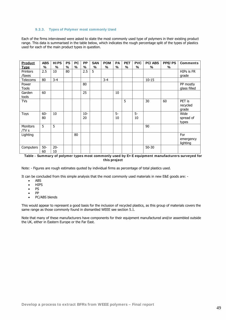
Develop a process to extract BFRs from WEEE polymers – Final report 49
9.3.3. Types of Polymer most commonly Used Each of the firms interviewed were asked to state the most commonly used type of polymers in their existing product range. This data is summarised in the table below, which indicates the rough percentage split of the types of plastics used for each of the main product types in question.
Table - Summary of polymer types most commonly used by E+E equipment manufacturers surveyed for this project
Note: - Figures are rough estimates quoted by individual firms as percentage of total plastics used. It can be concluded from this simple analysis that the most commonly used materials in new E&E goods are: -
• ABS • HIPS • PS • PP • PC/ABS blends
This would appear to represent a good basis for the inclusion of recycled plastics, as this group of materials covers the same range as those commonly found in dismantled WEEE see section 5.1. Note that many of these manufacturers have components for their equipment manufactured and/or assembled outside the UK, either in Eastern Europe or the Far East.
Product Type
ABS %
HIPS %
PS %
PC %
PP %
SAN%
POM%
PA%
PET%
PVC%
PC/ABS%
PPE/PS %
Comments
Printers /faxes
2.5 10 80 2.5 5 HIPs is FR grade
Telecoms 80 3-4 3-4 10-15 Power Tools
80 PP mostly glass filled
Garden tools
60 25 10
TVs 5 30 60 PET is recycled grade
Toys 60-80
10 10-20
5-10
5-10
Wide spread of types
Monitors /TV s
5 5 90
Lighting 80 For emergency lighting
Computers 50-60
20-10
50-30
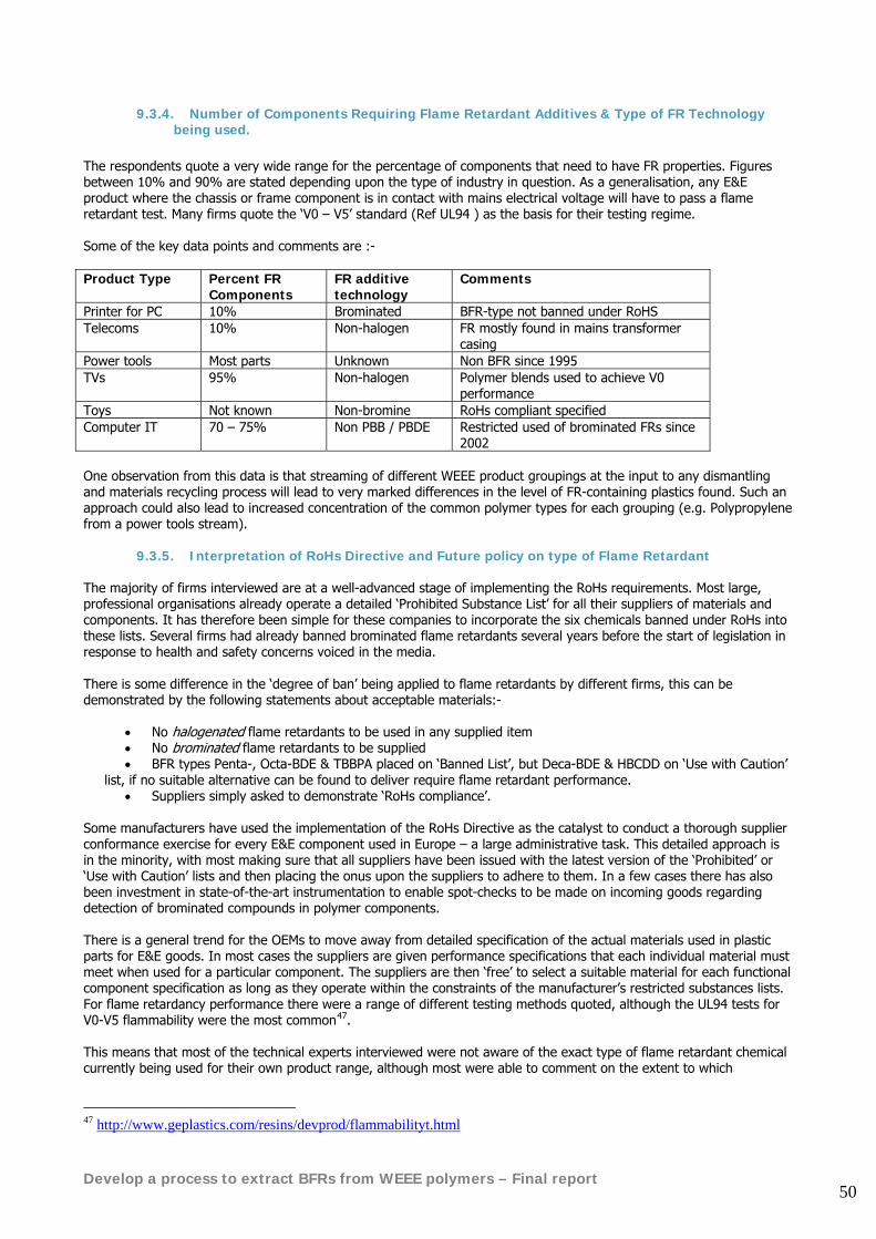
Develop a process to extract BFRs from WEEE polymers – Final report 50
9.3.4. Number of Components Requiring Flame Retardant Additives & Type of FR Technology being used.
The respondents quote a very wide range for the percentage of components that need to have FR properties. Figures between 10% and 90% are stated depending upon the type of industry in question. As a generalisation, any E&E product where the chassis or frame component is in contact with mains electrical voltage will have to pass a flame retardant test. Many firms quote the ‘V0 – V5’ standard (Ref UL94 ) as the basis for their testing regime. Some of the key data points and comments are :- Product Type Percent FR
Components FR additive technology
Comments
Printer for PC 10% Brominated BFR-type not banned under RoHS Telecoms 10% Non-halogen FR mostly found in mains transformer
casing Power tools Most parts Unknown Non BFR since 1995 TVs 95% Non-halogen Polymer blends used to achieve V0
performance Toys Not known Non-bromine RoHs compliant specified Computer IT 70 – 75% Non PBB / PBDE Restricted used of brominated FRs since
2002 One observation from this data is that streaming of different WEEE product groupings at the input to any dismantling and materials recycling process will lead to very marked differences in the level of FR-containing plastics found. Such an approach could also lead to increased concentration of the common polymer types for each grouping (e.g. Polypropylene from a power tools stream).
9.3.5. Interpretation of RoHs Directive and Future policy on type of Flame Retardant The majority of firms interviewed are at a well-advanced stage of implementing the RoHs requirements. Most large, professional organisations already operate a detailed ‘Prohibited Substance List’ for all their suppliers of materials and components. It has therefore been simple for these companies to incorporate the six chemicals banned under RoHs into these lists. Several firms had already banned brominated flame retardants several years before the start of legislation in response to health and safety concerns voiced in the media. There is some difference in the ‘degree of ban’ being applied to flame retardants by different firms, this can be demonstrated by the following statements about acceptable materials:-
• No halogenated flame retardants to be used in any supplied item • No brominated flame retardants to be supplied • BFR types Penta-, Octa-BDE & TBBPA placed on ‘Banned List’, but Deca-BDE & HBCDD on ‘Use with Caution’
list, if no suitable alternative can be found to deliver require flame retardant performance. • Suppliers simply asked to demonstrate ‘RoHs compliance’.
Some manufacturers have used the implementation of the RoHs Directive as the catalyst to conduct a thorough supplier conformance exercise for every E&E component used in Europe – a large administrative task. This detailed approach is in the minority, with most making sure that all suppliers have been issued with the latest version of the ‘Prohibited’ or ‘Use with Caution’ lists and then placing the onus upon the suppliers to adhere to them. In a few cases there has also been investment in state-of-the-art instrumentation to enable spot-checks to be made on incoming goods regarding detection of brominated compounds in polymer components. There is a general trend for the OEMs to move away from detailed specification of the actual materials used in plastic parts for E&E goods. In most cases the suppliers are given performance specifications that each individual material must meet when used for a particular component. The suppliers are then ‘free’ to select a suitable material for each functional component specification as long as they operate within the constraints of the manufacturer’s restricted substances lists. For flame retardancy performance there were a range of different testing methods quoted, although the UL94 tests for V0-V5 flammability were the most common47. This means that most of the technical experts interviewed were not aware of the exact type of flame retardant chemical currently being used for their own product range, although most were able to comment on the extent to which
47 http://www.geplastics.com/resins/devprod/flammabilityt.html
Develop a process to extract BFRs from WEEE polymers – Final report 51
brominated FR-compounds were still present. For example, “Our plastic casings are now all BFR-free, although halogenated compounds are still present in some circuit boards, until a viable alternative can be found”. There was limited knowledge about the actual level of a brominated compound that would be accepted in a ‘BFR-free’ material. Those interviewed who held an opinion on this subject referred to the ‘0.1% by weight’ limits in the draft legislation, although one firm stated that they were using 80% of the RoHs limit as their own ‘maximum acceptable level’ in any incoming material.
9.3.6. Current Usage of Recycled Polymers and Company policy in Future Use of post-consumer recycled polymers in new E&E goods is very limited at present. Only two of the firms interviewed had a specific policy to use recycled plastics, with one of them aiming to reach 20% of material made from recycled sources in next 5 years. Some industries positively exclude recycled material in ‘critical parts’ citing the perceived risk of contamination and associated product liability risk as the reasons for this (e.g. hand-held power tool casing; children’s toys). One company had a upper limit of 15% for the inclusion of recycled polymer, as long as performance was acceptable. There was a general viewpoint that ‘post-industrial’ scraps could be used up to levels of ~25%, but this really refers to the common practice of regrinding mould ‘sprues’ in high volume injection moulding factories where the risk of contamination or polymer mixing is negligible. With firms tending towards ‘performance specification’ as the basis for component supply, it is possible that recycled polymers are being used at increasing, but undetected, levels at present, following a natural economic driver to do so. So long as the performance is above the specified limits, E&E manufacturers would find it difficult to detect inclusion of recycled material in place of virgin compounds. Companies’ future policy regarding the use of recycled plastics depends upon their current stage of development towards using such materials. Only the one clear ‘future target level’ of 20% recycled content was quoted, with others declaring ‘an accepted, company wide policy’ to increase recycled use. The response of 70% of the interviewees can best be summed-up as: ‘no actual policy yet, but have talked about it’. For most firms however, the current focus is upon implementing the RoHs & WEEE Directives’ obligatory requirements, so that being ‘encouraged to integrate recycled material’ is being given lower priority.
9.3.7. Target Components & Plastic Specifications for Recycled Material It is not surprising, given the low level of usage for recycled polymers in E&E goods, that the typical components selected for ‘first-off’ targets to test addition of recycled resins were as follows: -
• Non-critical part • Hidden from sight in product internals or on base • Black in colour • Surface finish not important • Low mechanical stress
Some of the named parts for possible early testing of post-consumer addition were:-
• Fan shroud in computer cabinet; • Power Tool carry-case; • Blade cover for garden trimmer; • Internal brackets for TV / Hi-Fi.
The examples given from the companies that are currently using recycled material were (i) printer toner cartridge made from polystyrene; (ii) speaker boxes made from PET. This PET was recovered from post-use bottles rather than from E&E equipment. It is interesting to note that in example (i) a key driver for change was created by the ‘green’ purchasing policy of public sector buyers actually specifying a requirement for recycled printer cartridges in preference to brand-new OEM consumables. In example (ii), above, problems sourcing sufficient volume of acceptable quality recycled material were stated as a barrier to increasing recycled content. Some of the interviewed managers had been involved in exercises to test the feasibility of recycling plastics from their own-brand of products (e.g. customer returned goods). This had demonstrated that it was possible to obtain a satisfactory grade of recycled polymer from dismantling, sorting and cleaning the plastic. Obviously the known origin of the polymer resins makes it much easier to achieve material quality standards; however this ‘own-brand’ post-consumer route does offer a potential opportunity to WEEE dismantlers, who may find it economically feasible to sort some of the
Develop a process to extract BFRs from WEEE polymers – Final report 52
common makes and colours of plastic by manufacturer or product brand-name (e.g. bright orange polypropylene used in ‘Flymo’ garden tools). Most of the companies which were interested in including recycled polymers in their products were prepared to consider the idea of sourcing recycled material in Europe for use by their component suppliers overseas. Several of the companies were able to supply us with material specification sheets for the branded, virgin polymers currently being used in the manufacture of ‘target’ components. This data is specific to each individual application and polymer type, so is not reported here. However it does provide some benchmark figures that can be used for comparison of the potential performance of recycled polymers.
9.3.8. Main Issues / barriers to acceptance – comments The experts interviewed during the survey were given an opportunity to voice their own opinions about the main issues regarding closed-loop recycling of WEEE plastics back into new E&E goods. The responses had some common themes under the following subjects: -
• Quality o Concern that ‘equal to virgin’ quality and performance standards could not be achieved with recycled
polymer o Consistency of supplied recyclate quality – potentially more variable
• Volume o Insufficient tonnage of on-specification recycled resins available in market o Potential large-volume WEEE recyclers not geared-up for plastics recovery
• Location o Collected WEEE plastic may be remote from manufacturing site (i.e. Europe to Asia)
• Additives o BFR and other flame retardants now on ‘Prohibited Lists’ of materials for manufacturers based in
Europe although many manufacturers in Asia and the Far East continue to use BFRs because they provide an effective and low cost means of achieving fire safety standards.
o Other undesirable additives in old plastics e.g. cadmium • Risk
o Perceived increased risk of critical product failures caused by contamination of recyclate o Only prepared to use known-origin plastic from ‘own-brand’ recycling loops
• Legislation o Some industries have several other legal obligations related to the products (e.g. EN50088 – Safety in
electronic toys). o Position of recycled materials under REACH legislation?
• Cost o Can cost parity (or better) be achieved for recycled resins o Is total energy and monetary ‘life-cycle’ cost better than virgin raw material? o Cost of quality testing on small recycled batches can be prohibitive
The above list of opinions and concerns about the use or recycled resins indicates that the market is still in its early stages of development. It is encouraging to note that 3 of the firms are already beginning to utilise post-consumer material in new E&E products. These ‘early entrants’ into the recycled raw-material market will gradually overcome the challenges and create a ‘pull-through’ effect on their competitors. There are also some significant changes in the economic and consumer environment that create increased pressure to use recycled polymers. Recent increases in oil prices have had dramatic impact upon the cost of virgin plastics and a continued groundswell of environmentally conscious consumers, whose purchase decisions are influenced by the ‘green’ credential of products, being two examples of such change.
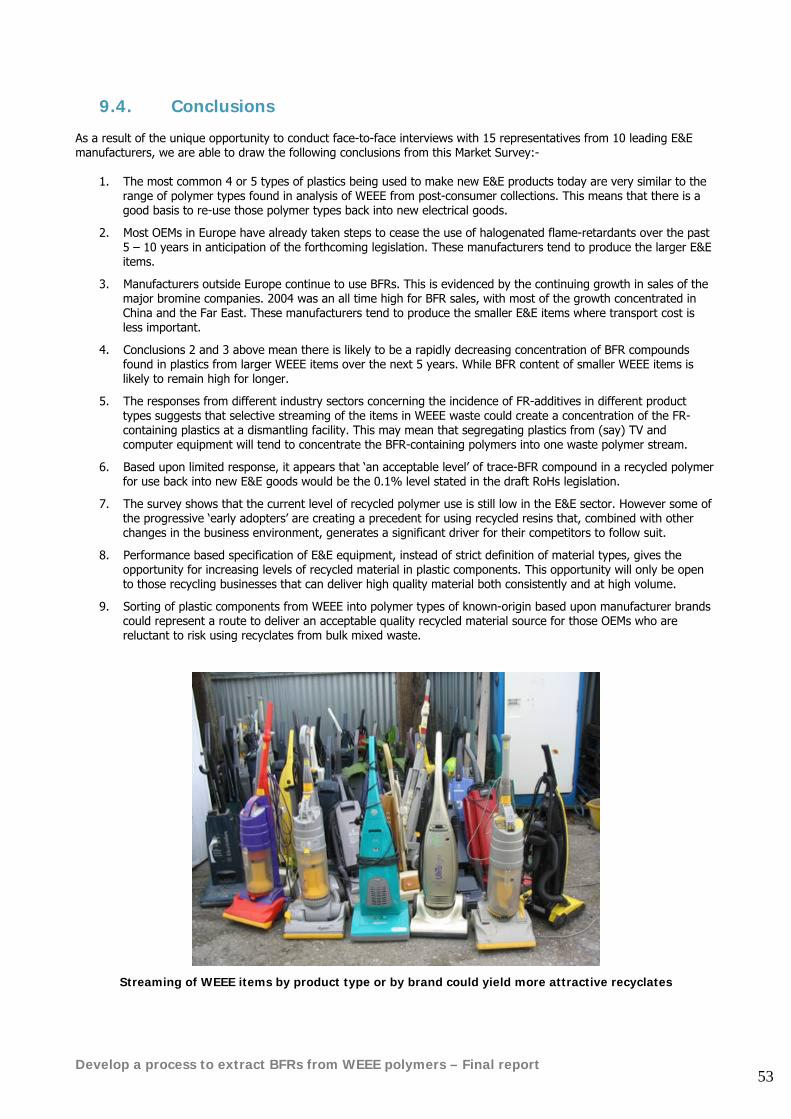
Develop a process to extract BFRs from WEEE polymers – Final report 53
9.4. Conclusions As a result of the unique opportunity to conduct face-to-face interviews with 15 representatives from 10 leading E&E manufacturers, we are able to draw the following conclusions from this Market Survey:-
1. The most common 4 or 5 types of plastics being used to make new E&E products today are very similar to the range of polymer types found in analysis of WEEE from post-consumer collections. This means that there is a good basis to re-use those polymer types back into new electrical goods.
2. Most OEMs in Europe have already taken steps to cease the use of halogenated flame-retardants over the past 5 – 10 years in anticipation of the forthcoming legislation. These manufacturers tend to produce the larger E&E items.
3. Manufacturers outside Europe continue to use BFRs. This is evidenced by the continuing growth in sales of the major bromine companies. 2004 was an all time high for BFR sales, with most of the growth concentrated in China and the Far East. These manufacturers tend to produce the smaller E&E items where transport cost is less important.
4. Conclusions 2 and 3 above mean there is likely to be a rapidly decreasing concentration of BFR compounds found in plastics from larger WEEE items over the next 5 years. While BFR content of smaller WEEE items is likely to remain high for longer.
5. The responses from different industry sectors concerning the incidence of FR-additives in different product types suggests that selective streaming of the items in WEEE waste could create a concentration of the FR-containing plastics at a dismantling facility. This may mean that segregating plastics from (say) TV and computer equipment will tend to concentrate the BFR-containing polymers into one waste polymer stream.
6. Based upon limited response, it appears that ‘an acceptable level’ of trace-BFR compound in a recycled polymer for use back into new E&E goods would be the 0.1% level stated in the draft RoHs legislation.
7. The survey shows that the current level of recycled polymer use is still low in the E&E sector. However some of the progressive ‘early adopters’ are creating a precedent for using recycled resins that, combined with other changes in the business environment, generates a significant driver for their competitors to follow suit.
8. Performance based specification of E&E equipment, instead of strict definition of material types, gives the opportunity for increasing levels of recycled material in plastic components. This opportunity will only be open to those recycling businesses that can deliver high quality material both consistently and at high volume.
9. Sorting of plastic components from WEEE into polymer types of known-origin based upon manufacturer brands could represent a route to deliver an acceptable quality recycled material source for those OEMs who are reluctant to risk using recyclates from bulk mixed waste.
Streaming of WEEE items by product type or by brand could yield more attractive recyclates
Develop a process to extract BFRs from WEEE polymers – Final report 54
10. WEEE polymer compatibility with new EEE polymers
10.1. Introduction This section of the report provides an overview of the important technical issues to consider when using recycled polymer to manufacture new goods. It includes experience-based knowledge gained from re-processing of the most common WEEE plastic types. Before describing particular materials and their properties some general points should be considered: Incompatibility of most polymer types when mixed with each other, resulting in poor toughness of the material and problems with the different processing melt temperatures required for the different components. Many other properties, such as stiffness, have some average value of those of the individual components. Hence it is best not to let the different plastics get mixed up in the first place. If they do then it is usually necessary to separate them. Colour Plastics are usually coloured and mixtures of different colours usually lead to a dull unattractive shade e.g. a dirty grey or green. Hence recyclate is often pigmented a dark colour (often black) to mask this and to give consistency of colour. Degradation Recycling involves reprocessing, i.e. heating to melt the material – usually at least twice, once to produce granules suitable for feeding to a processing machine (such as an injection moulding machine) and once for the shaping operation. Each time a plastic is heated and processed (involving high shear) some loss in properties occurs, especially toughness. However, several investigations at London Metropolitan University and elsewhere on the effects of repeated reprocessing have shown that little loss in properties occurs. Some particular plastics are especially sensitive though. Often heat stabilisers are added to recyclate to minimise problems especially with particularly heat sensitive plastics – mostly PVC and acetal. Material may also become degraded during its normal service lifetime before recycling, especially if it has been exposed to sunlight or high temperatures for long times. Flow/processability For shaping operations (processing) plastics need to have adequate melt flow. Better flow properties are required for some processes, e.g. injection moulding, than others. For example profile extrusion requires higher viscosity polymer. Especially good flow is needed for injection moulding of products with thin sections and/or long flow paths. As a result not all recyclate can be used to produce all shaped products.
Develop a process to extract BFRs from WEEE polymers – Final report 55
10.2. The Particular Materials Materials are chosen for the optimum combination of end-use properties and adequate processability at an acceptable cost. Plastics are used in electrical products mainly in housings especially for computers and televisions. The most commonly used materials for these applications are high impact polystyrene (HIPS), acrylonitrile-butadiene-styrene (ABS) and blends of ABS with polycarbonate (PC). Housings for other consumer products such as carpet cleaners, electric mowers and jug kettles may be made of polypropylene (PP). More specialist materials, such as PTFE and polybutlyene terephthalate (PBT) are often used for electrical components such as connectors and coil formers and for high performance mouldings such as power tool housings. Any mechanical components such as gears, cams and bearings will most likely be of acetal or nylon. Thus we have to consider a wide range of plastics materials.
10.2.1. HIPS and ABS o Easily processed materials with good flow o In effect rubber toughened polystyrene o Can be of variable composition (especially ABS) but rarely contain glass fibres or mineral fillers o No particular problems with heat stability, though ABS has a lower heat stability o Both are tough plastics, especially ABS o ABS is noted for its ability to produce attractive, smooth glossy surfaces o Should be no major particular problems on recycling
10.2.2. ABS/Polycarbonate (PC) blend
o PC alone is not often used in electrical products o ABS and PC are separately compatible with several other plastics as well as with each other o The PC improves the heat resistance of the ABS o The ABS improves the melt flow of the PC o The combination is very tough o PC needs thorough drying before melt processing o PC is more expensive
10.2.3. Polypropylene
o Often the first choice for injection moulding due to its low cost and reasonable end-use properties o No particular problems but is sensitive to atmospheric oxidation resulting from exposure to high
temperatures or sunlight. Thus recyclate may need addition of appropriate stabilisers if it is to be used for products which are exposed to these conditions
o Frequently reinforced with glass fibres to improve mechanical properties, especially stiffness, including in some electrical products, but not usually in housings
10.2.4. Nylon
o Several different types, but usually nylon 6 or nylon 66 and they are very similar o Very water sensitive absorbing large quantities (up to 8%) from the atmosphere, therefore must be
thoroughly dried before processing
10.2.5. Acetal o Similar end-use properties to nylons, both very often being used for similar products o Sensitive to heat degradation during processing, so must be stabilised. Degradation catalysed by
acids, so must never be used in machines used for processing PVC or used with halogenated fire retardants since both produce acids when heated. Must be flame retarded with phosphorus materials.
Typical values of the properties of these plastics are shown in section 10.3.4.
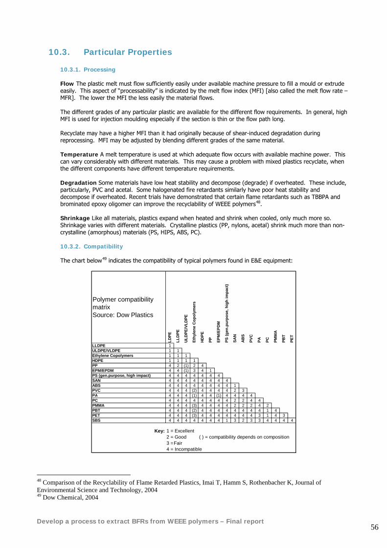
Develop a process to extract BFRs from WEEE polymers – Final report 56
10.3. Particular Properties
10.3.1. Processing
Flow The plastic melt must flow sufficiently easily under available machine pressure to fill a mould or extrude easily. This aspect of “processability” is indicated by the melt flow index (MFI) [also called the melt flow rate – MFR]. The lower the MFI the less easily the material flows. The different grades of any particular plastic are available for the different flow requirements. In general, high MFI is used for injection moulding especially if the section is thin or the flow path long. Recyclate may have a higher MFI than it had originally because of shear-induced degradation during reprocessing. MFI may be adjusted by blending different grades of the same material. Temperature A melt temperature is used at which adequate flow occurs with available machine power. This can vary considerably with different materials. This may cause a problem with mixed plastics recyclate, when the different components have different temperature requirements. Degradation Some materials have low heat stability and decompose (degrade) if overheated. These include, particularly, PVC and acetal. Some halogenated fire retardants similarly have poor heat stability and decompose if overheated. Recent trials have demonstrated that certain flame retardants such as TBBPA and brominated epoxy oligomer can improve the recyclability of WEEE polymers48. Shrinkage Like all materials, plastics expand when heated and shrink when cooled, only much more so. Shrinkage varies with different materials. Crystalline plastics (PP, nylons, acetal) shrink much more than non-crystalline (amorphous) materials (PS, HIPS, ABS, PC). 10.3.2. Compatibility
The chart below49 indicates the compatibility of typical polymers found in E&E equipment:
Polymer compatibility matrix Source: Dow Plastics
LDPE
LLD
PE
ULD
PE/V
LDPE
Ethy
lene
Cop
olym
ers
HD
PE
PP EPM
/EPD
M
PS (g
en.p
urpo
se, h
igh
impa
ct)
SAN
AB
S
PVC
PA PC PMM
A
PBT
PET
LLDPE 1ULDPE/VLDPE 1 1Ethylene Copolymers 1 1 1HDPE 1 1 1 1PP 4 2 (1) 2 4EPM/EPDM 4 4 (1) 3 4 1PS (gen.purpose, high impact) 4 4 4 4 4 4 4SAN 4 4 4 4 4 4 4 4ABS 4 4 4 4 4 4 4 4 1PVC 4 4 4 (2) 4 4 4 4 2 3PA 4 4 4 (1) 4 4 (1) 4 4 4 4PC 4 4 4 4 4 4 4 4 2 2 4 4PMMA 4 4 4 (3) 4 4 4 4 2 2 2 4 2PBT 4 4 4 (2) 4 4 4 4 4 4 4 4 1 4PET 4 4 4 (3) 4 4 4 4 4 4 4 3 1 4 3SBS 4 4 4 4 4 4 4 1 3 2 3 3 4 4 4 4
Key: 1 = Excellent2 = Good ( ) = compatibility depends on composition3 =Fair4 = Incompatible
48 Comparison of the Recyclability of Flame Retarded Plastics, Imai T, Hamm S, Rothenbacher K, Journal of Environmental Science and Technology, 2004 49 Dow Chemical, 2004
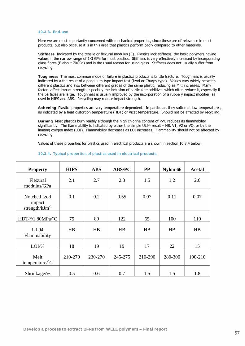
Develop a process to extract BFRs from WEEE polymers – Final report 57
10.3.3. End-use
Here we are most importantly concerned with mechanical properties, since these are of relevance in most products, but also because it is in this area that plastics perform badly compared to other materials. Stiffness Indicated by the tensile or flexural modulus (E). Plastics lack stiffness, the basic polymers having values in the narrow range of 1-3 GPa for most plastics. Stiffness is very effectively increased by incorporating glass fibres (E about 70GPa) and is the usual reason for using glass. Stiffness does not usually suffer from recycling Toughness The most common mode of failure in plastics products is brittle fracture. Toughness is usually indicated by a the result of a pendulum-type impact test (Izod or Charpy type). Values vary widely between different plastics and also between different grades of the same plastic, reducing as MFI increases. Many factors affect impact strength especially the inclusion of particulate additives which often reduce it, especially if the particles are large. Toughness is usually improved by the incorporation of a rubbery impact modifier, as used in HIPS and ABS. Recycling may reduce impact strength. Softening Plastics properties are very temperature dependent. In particular, they soften at low temperatures, as indicated by a heat distortion temperature (HDT) or Vicat temperature. Should not be affected by recycling. Burning Most plastics burn readily although the high chlorine content of PVC reduces its flammability significantly. The flammability is indicated by either the simple UL94 result – HB, V1, V2 or VO, or by the limiting oxygen index (LOI). Flammability decreases as LOI increases. Flammability should not be affected by recycling. Values of these properties for plastics used in electrical products are shown in section 10.3.4 below.
10.3.4. Typical properties of plastics used in electrical products
Property HIPS ABS ABS/PC PP Nylon 66 Acetal
Flexural modulus/GPa
2.1 2.7 2.8 1.5 1.2 2.6
Notched Izod impact
strength/kJm-1
0.1 0.2 0.55 0.07 0.11 0.07
[email protected]/oC 75 89 122 65 100 110
UL94 Flammability
HB HB HB HB HB HB
LOI/% 18 19 19 17 22 15
Melt temperature/oC
210-270 230-270 245-275 210-290 280-300 190-210
Shrinkage/% 0.5 0.6 0.7 1.5 1.5 1.8
Develop a process to extract BFRs from WEEE polymers – Final report 58
10.4. Conclusions
• Polymer types are generally incompatible with each other, leading to melting problems and reductions in toughness when they are mixed together. It is therefore important that recycling processes ensure good separation by polymer type
• The following polymer properties are unlikely to be affected significantly by recycling and will produce an average property when recyclates and virgin materials are blended:
o Stiffness o Softening point o Flammability
• Most WEEE polymer types do not suffer major degradation in mechanical recycling processes and can therefore be re-used or mixed with virgin material without significant loss of physical properties.
• Some halogenated flame retardants and certain polymers such as acetal and PVC have a tendency to suffer thermal degradation if subjected to multiple thermal processes. However recent trials with the brominated ‘backbone’ flame retardants TBBPA and brominated epoxy oligomer have demonstrated that these flame retardants can improve the recyclability of some polymers.
Develop a process to extract BFRs from WEEE polymers – Final report 59
11. Methods to detect and measure BFR type and concentration in WEEE polymers
11.1. Introduction The WEEE Directive requires recyclers of plastics from WEEE to identify the presence of BFR in plastics to be recycled. Any technique used must be suitable for implementation on a practical recycling line. This section of the report reviews the techniques available for identification of polymer types and whether or not polymers contain brominated flame retardants (BFRs). It then identifies which of these techniques may be suitable for use on automated sorting lines and reviews the capabilities of a selection of commercially available ‘state of the art’ polymer identification and BFR detection instruments. This background information will help to inform the bulk separation process designs proposed in Chapter 13 of the report.
11.2. Existing labels and markings The problems associated with plastics identification for recycling were highlighted in a recent exercise in which six 1m3 bags of real computer WEEE were transported from Associated Polymer Resources Ltd50 to the University of Southampton for analysis. The bags contained a large quantity of plastic housings from CPU’s, monitors and keyboards in various states of completeness. Most of these pieces were marked with a material identification code and the load in total comprised some 12 different types. The markings were as follows: PS ABS PVC HIPS PS-HI PC+ABS ABS-FR ABS+FR(17) PC+ABS-FR PC+ABS FR(40) NORYL PPO-94VO The assumption is that the denotation FR refers to the presence of flame retardant but with no indication of type or concentration. It can not be assumed that those without the FR abbreviation do not contain BFR. Indeed, recent experiences have shown that markings cannot always be trusted as engraved or stamped moulds are known to be shared for different plastics.
50 Associated Polymer Resources Ltd. West field House, Knowle Hill, Allbrooke, Eastleigh, Hants. SO50 4LZ. UK
Develop a process to extract BFRs from WEEE polymers – Final report 60
11.3. Techniques for the detection of BFR’s Due to the relatively low levels of BFR in plastics and the way they are incorporated into the structure of the material it has been determined that with one exception only those methods based on spectroscopy can be practically used for their detection. The ‘COMBIDENT’ report51 lists ten different identification techniques:
• Near infra-red (NIR) spectroscopy • Mid infra-red (MIR) reflection spectroscopy • MIR pyrolysis spectroscopy • Raman scattering spectroscopy • Mass pyrolysis spectroscopy • Sliding spark (spark ablation) spectroscopy • X-ray fluorescence spectroscopy • MIR Acousto-optic tunable filter (MIR AOTF) spectroscopy • Laser induced thermal impulse response(TIR) • Laser induced plasma spectroscopy (LIPS) spectroscopy
TIR is a non-spectroscopic technique and analyses the macroscopic heat produced by the sample surface. The COMBIDENT report suggests that from the above list MIR AOTF, TIR and LIPS are best suited to an automated line due to (a) sampling speed and (b) ability to work on black plastics. Section 3.2 of the COMBIDENT report tabulates the relative performance of each of the three techniques. The above report also comments on the presence of surface treatments, coatings and contamination which can greatly affect the accuracy of some of the identification techniques. The method found to be most successful was blasting with plastic powder or grinding media. Commercial equipment is available to perform this although it is expensive and requires a long treatment time. In the end the prototype line for the COMBIDENT project used industrial brushes including silicone carbide to abrade the plastic surfaces.
11.3.1. Thermal impulse response (TIR) A CO2 laser (10.6μm) is used to heat a small area of the sample surface. Depending on the materials properties such as absorption coefficient, thermal conductivity etc. a specific time-dependant temperature distribution is generated. This is detected by means of an infra-red thermographic system. Since the temperature distribution is likely to be influenced by the presence of flame retardants this method is feasible however the detection of low levels of BFR and the ability to distinguish between different types has not been proven. A major disadvantage of this technique is that it does not work with black plastic and this lead to it being dropped from the prototype identification line developed in the COMBIDENT project.
11.3.2. X-Ray Fluorescence Analysis (XRF) Drinks bottles are commonly made of PVC or PET. These items are often collected under recycling schemes. The requirement for very low levels of PVC in a PET product led to the development of automated sorting systems based on identification of PVC using XRF in the 1980s. Systems were developed by National Recovery Technologies (NRT) Inc., Magnetic Separation Systems, Asoma and Govoni. When x-rays bombard the surface of a material secondary x-rays are generated which have wavelengths characteristic of the elements contained within the material. The production of x-rays from excited chlorine atoms is used to identify PVC. Following identification a computer controlled air ejection system can be used to remove the PVC bottles from a mixed plastic waste stream52. The separators, with multiple analyses (up to 200 per second) on each bottle, are capable of highly efficient removal of PVC. The detector must be close to the bottle because of the attenuation of x-rays in air. Failure to detect the characteristic x-rays can result from the 'sandwiching' of a PVC bottle between other polymer types. This may be caused by a failure to deliver a single bottle stream through the unit and is more likely to occur when the feed material has been compacted. Labels on PVC bottle are also reported to cause reduced transmission and hence reduced efficiency.
51 COMBIDENT Final Technical Report, EU Contract No BRPR-CT98-0778, December 2001 52 Summers, Mikofalvy & Little. ‘Use of X-ray fluorescence for sorting vinyl from other packaging materials in municipal solid waste’. J.Vinyl.Tech. 12, No.3, Sept. 1990, 161-164. 411966
Develop a process to extract BFRs from WEEE polymers – Final report 61
The NRT ‘VinylCycle’ separator53 was installed at the Reprise plant near Blackpool, England in 1990 and operated at a sorting rate of 20,000 bottles per hour, equivalent to 1 tonne per hour. NRT also supply a separator with a higher throughput of 2.27 tonnes per hour. Spectrometers based on energy dispersive X-ray analysis (EDAX) are traditionally laboratory based systems. Their cost and complexity plus the issue of exposure of the work force to X-rays do not make them ideal for an industrial recycling line. Furthermore there is little evidence to show that they are efficient in detecting BFR’s. The US company Niton make a hand-held unit specifically designed to identify plastic additives.
11.3.3. Near Infrared (NIR) Spectroscopy According to Krummenacher et al54 NIR spectroscopy (700-2500 nm spectral range) is the most widely used identification method for automated plastic sorting. The infra-red irradiation is absorbed by overtone and combination vibrations that are characteristic of particular functional groups, such as O-H, N-H and CH. Different polymers can be readily identified provided that the objects do not contain additives such as carbon black, which cause excessive absorption of the radiation. Advantages of NIR compared to mid infrared spectroscopy (see below) include shorter response times, improved detection ability of the NIR photodetectors (germanium, indium arsenide or indium gallium arsenide) and the ability to use inexpensive quartz fibre optics with low attenuation. The Fraunhofer Institute of Chemical Technology has developed a fast on-line identification system for plastics using a NIR spectrometer with an acousto-optic tuneable filter (AOTF)55 56. Spectrometers used with an AOTF allow scan speeds of 200 nm per millisecond at a wavelength resolution of 2-5 nm in the region 1000-2500 nm. The Fraunhofer Institute have also developed a hand-held mobile diode-array grating spectrometer or Mobi-DAGS for the identification of plastics but it is not appropriate for BFR detection. Manufacturers of NIR sorting systems include National Recovery Technologies Inc. (NRT) which claims to have a high-speed IR separator called Flake Analyzer57 that can identify additives down to ppm levels but does not mention BFR’s. NRT supply units for whole plastic bottles (MultiSort) or flaked material (FlakeSort) giving throughput rates of up to 2.3 tonnes per hour. Other companies include Binder AG in Austria, and Integrated Recycling Systems (IRS) in England. MSS Inc. has recently developed a NIR sensing system that can identify polyethylene naphthalate (PEN)58. LLA in Germany also manufacture a plastics ID system based on NIR59. None of these companies make claims regarding BFR.
11.3.4. Fourier Transform Mid Infrared Spectroscopy According to Morley60 Fourier transform mid infrared spectroscopy (2,500-5,000 nm) is the most widely used system for identifying plastics. Instruments generate spectra in the 'fingerprint' region, which contains the fundamental vibration frequencies of the functional groups within molecules. The technique can be used to identify blends and fillers, and can identify dark objects. It is proven that this technique can detect the presence of BFR’s because they produce small differences in the reflected spectra. Most new infra-red spectrometers use a specular reflectance technique in which infrared light that is reflected from the surface is analysed. The surface of the object should therefore be relatively flat (a potential disadvantage in some systems but unlikely to be a problem in manual WEEE recycling). Analysis times greater than 1 second are commonly used. As the object has to be held stationary at the detector the technique does not lend itself perfectly to automated sorting. To improve the accuracy of identification the technique may be combined with pyrolysis units such as ‘Sliding Spark’ and LIBS, which analyse vapours derived from heating of the surface. Suppliers of bench top analysers include Bruker Optics and ThermoNicolet. The reflected spectrum is compared against a library of polymers which can include many hundred spectra and identifies the closest match, and (if required) the 'next best hit'. Measurement and identification take approximately 1-5 seconds depending on the number of surface scans, 53 Ottewill S., The Chemical Engineer, 15th Nov. 1990. p.19 54 Krummenacher, Peuch, Fischer & Biddle. ‘Automatic Identification and sorting of plastics from different waste streams – a status report’. APME, Brussels, 1998. 55 R 95 – Recovery, Recycling, Re-Integration. Vol III: Mechanical Processes, Logistic Networks, Separation Tech. Conf. Proc. Geneva 1-3 Sept. 1995. III 230-235. 8(13). 56 Eisenreich, Herz, Kull, Mayer & Rhoe, ‘Fast on-line identification of plastics by near-infrared spectroscopy for use in recycling processes’. Antec 96. Vol. III Conf. Proc. Indianapolis 5-10 May 1996. 3131-3135. 609107 57 www.nrt-inc.com/flakeA.htm 58 www.magsep.com/PprNP97.htm 59 www.lla.de/index.php 60 Morley N., ‘Current state-of-the-art in Sorting and Identification of Mixed Plastic Waste’. Polmer Recycling 3, No.3, 1997/98, 217-226. 736640
Develop a process to extract BFRs from WEEE polymers – Final report 62
the size of the library and the computer speed. The PolyAna purpose built plastic ID system is based on the ThermoNicolet spectrometer. Mid infra-red spectrometry for high-speed analysis of materials is often used with AOTF. These devices control the IR beam intensity and enable the beam to be rapidly switched on and off61.
11.3.5. Raman Spectroscopy Raman spectroscopy of inelastic light scattering is a technique that has until recently been restricted to the research laboratory, but has now been applied to plastics identification. Knights62 described the operation of the Rapid Plastics Identification System RP-1 supplied by SpectraCode Inc. A laser gun is placed on the object to be identified and a push button fires the laser at the object. The laser penetrates 100 μm into the object, so that thin coatings and irregularities should not affect the identification. Certain photons from the laser light will change frequency when they encounter the polymer molecules, whilst others do not. Holographic optical elements distinguish which photons have interacted allowing a Raman ‘molecular barcode’ to be generated. This information is transmitted to a computer console which has a software library of ‘molecular barcodes’ which can be compared with that produced by the object. SpectraCode63 claim that almost 100% accuracy is possible for a 1 second analysis time. Darkly pigmented materials can be identified, although it is reported that the system is somewhat sensitive to the presence of carbon black, which can reduce the reflection back to the detector. Raman spectroscopy has potential for automated sorting due to measurement times as low as 50 milliseconds.
11.3.6. Laser Desorption-Ion Mobility Spectroscopy - LIBS, LIPS & LIMES Laser Induced Breakdown Spectroscopy (LIBS) (also known as Laser Induced Plasma Spectroscopy (LIPS)) and Laser Induced Multi Emission Spectroscopy (LIMES)64 are simple, relatively inexpensive analytical techniques to determine the elemental composition of a sample, regardless of whether the sample is a solid, liquid or gas. A powerful laser is focused onto the sample and hot plasma is formed. Light emitted by the plasma is composed of spectral lines characterising the element present in the sample. This technique is sensitive to all elements, with typical limits of detection between 0.1-200 parts per million (depending on the sample and the element of interest). Minimal sample preparation is needed making it quick and easily adaptable to automated chemical monitoring equipment or portable units. The technique can be used in a variety of more complex analyses such as determination of alloy composition, origin of manufacture (by monitoring trace components), and molecular analysis (unknown identification). There is also the option for use in man-portable or robotics applications. Simpson et al65 used a relatively low powered laser to ablate organic material from the surface of a plastic. The vapours generated by the laser were transported using a carrier gas (air, argon or helium) to an ion, mobility spectrometer. Within the spectrometer the charged organic species are separated in a drift tube, with different species having characteristic drift times. The result from ion mobility spectrometry is a series of peaks at specific drift times. Testwork conducted with low-density polyethylene (LDPE), HDPE, PP, nylon 66, ABS, PET and PVC revealed that all the polymers exhibited characteristic outputs except PET. The lack of'signature' with PET was attributed to insufficient attenuation of the laser beam, and resultant lack of ablated material from the highly transparent sample. The method is reported to be well suited for the identification of other materials within a plastic, such as fillers, reinforcing agents and pigments. LIPS (LIBS) is claimed by the COMBIDENT report to work well in identifying the presence of BFR’s. Variation in the laser operating conditions, such as increased power, will cause a variation in the type of molecules generated at the surface and the 'signature' for a particular polymer will change. The technique therefore needs well-controlled operating conditions for consistent identification. The time taken for spectrum acquisition of approximately 0.1 to 1 second suggests the technique is applicable for the identification of plastics on a recycling line.
61 www.sciner.com/Acousto-Optics/AOTF.htm 62 Knights M., ‘Laser eye quickly identifies plastics in waste’ Plastics Technology 43, No. 12, Dec. 1997,24-25. 664147 63 www.spectracode.com 64 www.ltb-berlin.de/limes.html 65 Simpson, Anderson, McLeod & Cooke, ‘Polymer characterisation using laser desorption-ion mobility spectrometry’.
Analyst 118, No.4, April 1993, 449-451. 478440
Develop a process to extract BFRs from WEEE polymers – Final report 63
Stepputat & Noll66 ran a conveyor line at 0.5m.s-1 and using LIBS with an auto-focusing system identified the metals Cr, Hg, Cd and Pb in plastic samples with an accuracy of 84-95%. They had more difficulty with Br relying on determining the presence of BFR’s in the plastic by identifying Sb in the synergist compound Sb2O3. In the laboratory, they could detect Br directly at levels down to 1.5% by weight of plastic. This is sufficient to detect BFR in plastics which normally occur in concentrations exceeding 3% wt.
11.3.7. Spark Ablation (Sliding Spark) Sliding spark technique works in a similar way to LIBS but uses an energetic spark discharge to ablate the surface. The effectiveness of this system is similar to the LIBS technique and commercially available equipment such as the SlideSpec-S2 is specifically designed to identify BFR’s (see next section).
66 Stepputat & Noll,’On-line Detection of Heavy Metals and Brominated Flame Retardants in Technical Polymers with Laser-induced Breakdown Spectrometry’. Applied Optics Vol. 42, No. 30, Oct. 2003, 6210-6220
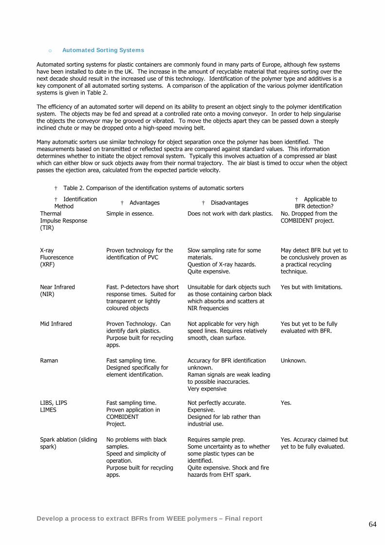
Develop a process to extract BFRs from WEEE polymers – Final report 64
o Automated Sorting Systems Automated sorting systems for plastic containers are commonly found in many parts of Europe, although few systems have been installed to date in the UK. The increase in the amount of recyclable material that requires sorting over the next decade should result in the increased use of this technology. Identification of the polymer type and additives is a key component of all automated sorting systems. A comparison of the application of the various polymer identification systems is given in Table 2. The efficiency of an automated sorter will depend on its ability to present an object singly to the polymer identification system. The objects may be fed and spread at a controlled rate onto a moving conveyor. In order to help singularise the objects the conveyor may be grooved or vibrated. To move the objects apart they can be passed down a steeply inclined chute or may be dropped onto a high-speed moving belt. Many automatic sorters use similar technology for object separation once the polymer has been identified. The measurements based on transmitted or reflected spectra are compared against standard values. This information determines whether to initiate the object removal system. Typically this involves actuation of a compressed air blast which can either blow or suck objects away from their normal trajectory. The air blast is timed to occur when the object passes the ejection area, calculated from the expected particle velocity.
† Table 2. Comparison of the identification systems of automatic sorters
† Identification Method † Advantages † Disadvantages † Applicable to
BFR detection? Thermal Impulse Response (TIR)
Simple in essence. Does not work with dark plastics. No. Dropped from the COMBIDENT project.
X-ray Fluorescence (XRF)
Proven technology for the identification of PVC
Slow sampling rate for some materials. Question of X-ray hazards. Quite expensive.
May detect BFR but yet to be conclusively proven as a practical recycling technique.
Near Infrared (NIR)
Fast. P-detectors have short response times. Suited for transparent or lightly coloured objects
Unsuitable for dark objects such as those containing carbon black which absorbs and scatters at NIR frequencies
Yes but with limitations.
Mid Infrared
Proven Technology. Can identify dark plastics. Purpose built for recycling apps.
Not applicable for very high speed lines. Requires relatively smooth, clean surface.
Yes but yet to be fully evaluated with BFR.
Raman Fast sampling time. Designed specifically for element identification.
Accuracy for BFR identification unknown. Raman signals are weak leading to possible inaccuracies. Very expensive
Unknown.
LIBS, LIPS LIMES
Fast sampling time. Proven application in COMBIDENT Project.
Not perfectly accurate. Expensive. Designed for lab rather than industrial use.
Yes.
Spark ablation (sliding spark)
No problems with black samples. Speed and simplicity of operation. Purpose built for recycling apps.
Requires sample prep. Some uncertainty as to whether some plastic types can be identified. Quite expensive. Shock and fire hazards from EHT spark.
Yes. Accuracy claimed but yet to be fully evaluated.
Develop a process to extract BFRs from WEEE polymers – Final report 65
11.4. Commercially available systems suitable for use on manual dismantling lines for WEEE
11.4.1. PolyAna Avatar
PolyAna Avatar available from Wolfson Electrostatics67 at the University of Southampton The PolyAna Avatar uses FT-IR reflectance spectroscopy operating in the spectral range 3-20μm. The blue section contains the special optics to bring the IR beam to the sample held at the nozzle. Cost is £22,000 including computer and various databases. The PolyAna is based on the original Millennium-Award-winning technology designed at the University of Southampton in collaboration with the Ford Motor Company68. It is specifically designed to provide a quick and accurate identification of unknown materials and will detect BFR’s in plastics. It can be used on large items (VDU housings, mouldings etc.) and small objects down to about 10mm. The test is non-destructive and does not require modification or treatment of the sample in any way. It is designed to be operated in an industrial environment by non-technical personnel and can be programmed to identify or distinguish between a large variety of materials. The PolyAna Avatar has already achieved good results in industrial trials providing a good level of accuracy with a measurement time down to 2 seconds. The PolyAna is based around the latest generation Nicolet Avatar Spectrometer with an integral optical cell and a supporting computer. The spectrometer uses a beam of mid infra-red wavelength light fired at a sample of unknown material to produce a spectrum from the reflected radiation. The infra-red beam is directed to the sample by means of a series of mirrors within the optical cell. The reflected light is similarly directed to a detector also housed in the spectrometer. The computer then compares the spectrum of the reflected light with a database or 'library' of pre-programmed spectra stored within the computer. Different libraries are available for different applications, and a 'custom' library can be easily set up by the user in order to deal with specific materials of interest. The PolyAna Avatar runs with MS Windows XP software. When presented with an unknown material the computer rapidly scans the spectrum of each of the plastics stored in the library and produces a list of the best matches with the sample together with their percentage fit.
67 Wolfson Electrostatics, Dept. of Electronics & Computer Science, University of Southampton SO17 1BJ England. Tel: 02380 552266/594995. Fax: 02380 593015. email: [email protected] www.soton.ac.uk/~wolfson 68 Ford Motor Company Research & Engineering Centre, Laindon, Basildon, Essex SS15 6EE England
Develop a process to extract BFRs from WEEE polymers – Final report 66
PolyAna display. Click on ‘Analyse Sample’ or use foot switch. Various libraries can be programmed into the device containing up to several hundred materials
Advantages: Requires little or no sample preparation Speed and simplicity of operation Compact rugged construction proven on recycling lines Relatively low cost compared with other spectrometer based techniques Disadvantages: Unproven on the full range of BFR’s and additives Likes flat, smooth light coloured surfaces Still quite expensive for the recycling industry
Develop a process to extract BFRs from WEEE polymers – Final report 67
11.4.2. Sony Plastics Identification Device
Sony Plastics ID system This device makes it possible to locate black plastics and plastics with flame retardants, formerly difficult to distinguish. Using mid-infra red reflectance spectroscopy and new algorithms, a 99% accuracy rate has been achieved69. Advantages Very high accuracies claimed ‘Reputable’ manufacturer Disadvantages Cumbersome Expensive Sampling time of 35 seconds impractical for recycling line
69 www.sony.net/SonyInfo/Environment/recycle/development/02.html
Develop a process to extract BFRs from WEEE polymers – Final report 68
11.4.3. Sliding Spark
The SlideSpec-S2 sliding spark spectrometer (left) and typical screen display (right) The SlideSpec-S270 uses an electrostatic spark to vaporise the surface of the plastic under test and sampling the emissions. Paints or contamination on the surface can be automatically removed by pre-sparking. Additive detection is performed by measuring simultaneously the characteristic emission lines of the elements of additives in the spectral region of approx. 210-500 nm. The intensities of selected spectral lines are compared with preset threshold values. After calibration with known samples, the system enables semi-quantitative analysis of inorganic contents down to the sub-%-region. A measurement time of 1 second is claimed. The basic principle of the method is the thermal vaporization of a small amount of the material surface using a train of defined high-current sliding sparks. The material components in the spark by plasma are vaporized, atomized and, activated to emit radiation. For analysis the sparking pistol is simply pressed on to the sample. The measurement begins by pressing the start button on the pistol grip. After sparking-off an integrated TFT-colour-screen displays the result. The hand measuring head is connected with 3 m protection conduits to the instrument. Optical signals are coupled via fibre optics to the spectrometer system. The portable device includes the CCD spectrometer unit, the spark generator and a computer, which steers and evaluates the identification process. The use of the software can be done by an integrated Touch Panel or by an external keyboard. Intensity data are saved in flat ASCII-format. The serial interface using a link program allows external data transfer (dimension in mm: 364x195x316, weight: 10 kg, electric power supply: 230 Volt-/50 Hz). Setting of different sparking conditions as well as the detailed spectra view and evaluation of the out coming atomic emission spectra enables to develop easily own applications (screening of woods, glasses, ceramics, textiles, leather goods, dried sludge, varnishes, paintings etc.). Advantages No problems with black samples Speed and simplicity of operation Disadvantages Requires some sample preparation Some uncertainty as to whether some plastic types can be identified (ie. HIPS from ABS, PE from PP etc) Potential shock and fire hazards from high voltage sparks.
70 www.iosys-seidel.de/slidespec_e.htm
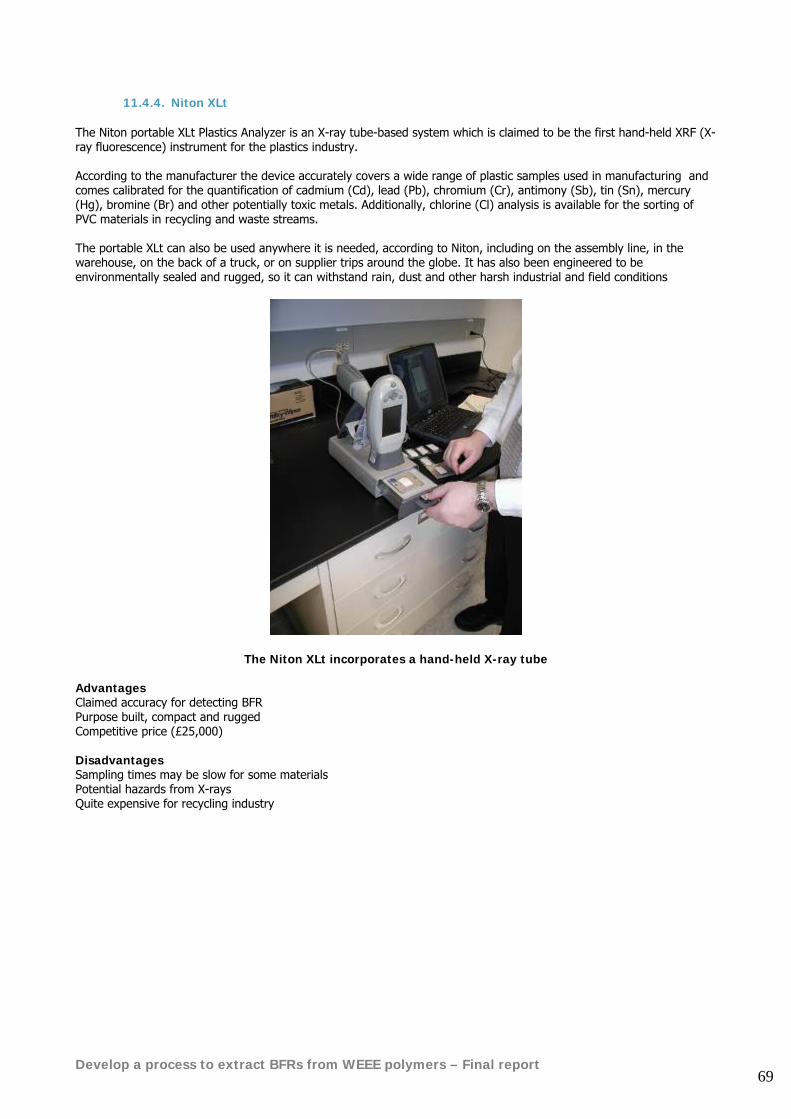
Develop a process to extract BFRs from WEEE polymers – Final report 69
11.4.4. Niton XLt The Niton portable XLt Plastics Analyzer is an X-ray tube-based system which is claimed to be the first hand-held XRF (X-ray fluorescence) instrument for the plastics industry. According to the manufacturer the device accurately covers a wide range of plastic samples used in manufacturing and comes calibrated for the quantification of cadmium (Cd), lead (Pb), chromium (Cr), antimony (Sb), tin (Sn), mercury (Hg), bromine (Br) and other potentially toxic metals. Additionally, chlorine (Cl) analysis is available for the sorting of PVC materials in recycling and waste streams. The portable XLt can also be used anywhere it is needed, according to Niton, including on the assembly line, in the warehouse, on the back of a truck, or on supplier trips around the globe. It has also been engineered to be environmentally sealed and rugged, so it can withstand rain, dust and other harsh industrial and field conditions
The Niton XLt incorporates a hand-held X-ray tube Advantages Claimed accuracy for detecting BFR Purpose built, compact and rugged Competitive price (£25,000) Disadvantages Sampling times may be slow for some materials Potential hazards from X-rays Quite expensive for recycling industry
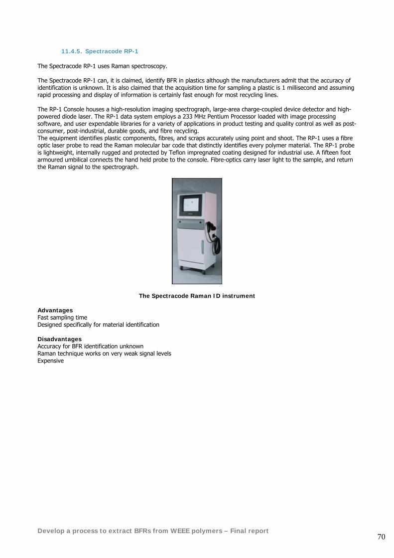
Develop a process to extract BFRs from WEEE polymers – Final report 70
11.4.5. Spectracode RP-1 The Spectracode RP-1 uses Raman spectroscopy. The Spectracode RP-1 can, it is claimed, identify BFR in plastics although the manufacturers admit that the accuracy of identification is unknown. It is also claimed that the acquisition time for sampling a plastic is 1 millisecond and assuming rapid processing and display of information is certainly fast enough for most recycling lines. The RP-1 Console houses a high-resolution imaging spectrograph, large-area charge-coupled device detector and high-powered diode laser. The RP-1 data system employs a 233 MHz Pentium Processor loaded with image processing software, and user expendable libraries for a variety of applications in product testing and quality control as well as post-consumer, post-industrial, durable goods, and fibre recycling. The equipment identifies plastic components, fibres, and scraps accurately using point and shoot. The RP-1 uses a fibre optic laser probe to read the Raman molecular bar code that distinctly identifies every polymer material. The RP-1 probe is lightweight, internally rugged and protected by Teflon impregnated coating designed for industrial use. A fifteen foot armoured umbilical connects the hand held probe to the console. Fibre-optics carry laser light to the sample, and return the Raman signal to the spectrograph.
The Spectracode Raman ID instrument Advantages Fast sampling time Designed specifically for material identification Disadvantages Accuracy for BFR identification unknown Raman technique works on very weak signal levels Expensive
Develop a process to extract BFRs from WEEE polymers – Final report 71
11.5. Conclusions The following broad conclusions can be drawn from this review: Because of the way flame retardants are incorporated into plastics and the concentrations in which they are present the methods for their detection are limited to around 9 techniques all based on spectroscopy. BFR detection in recycling is in its infancy and many of these techniques have been developed for the laboratory rather than a recycling line. This means they are generally expensive, relatively fragile and not particularly user-friendly. Other current recycling techniques based on macro-physical properties of plastics such as density separation, surface hardness, electrostatics etc. will not identify the presence of BFR’s. Thermal Imaging Response (TIR) which monitors the heating of the surface in response to an incident CO2 laser beam may detect BFR’s in similar light coloured plastics. Bromine is not the easiest element to detect using spectroscopy and the LIBS technique for example identifies the presence of BFR by detecting Antimony (Sb) in the Br synergist compound Sb2O3. This also probably applies to the Sliding-Spark technique. Another technique FT-IR is less specific in the way it detects BFR; in this case relying on a small but significant shift in the spectral pattern of reflected radiation between BFR and non-BFR plastics. Neither of these points are important however for recycling applications since a simple streaming of BFR and non-BFR is all that is required. Of the nine techniques, surface ablation by LIBS or sliding spark and FT-mid IR appear to be the most suitable for BFR detection with X-ray fluorescence in third place. It is no surprise therefore that it is these three methods which have produced purpose-built commercial instruments aimed both in terms of cost and practicality at the recycling industry. The instruments in question; SlideSpec, PolyAna and Niton XLt are similar in many ways and currently appear to set the benchmark for this application. They are similar in size, cost, sampling speed and ergonomics of use. (Note. It is assumed that the SlideSpec is similar in cost to the other two. Three attempts to obtain a price from the company were unanswered). LIBS equipment is generally available but appears more complex and expensive. Recent attempts to run LIBS on a recycling line resulted in a reduction in accuracy compared with its operation in the laboratory. We are not aware of any ‘stand-alone’ LIBS system specifically targeted at BFR detection for industrial recycling although it is hinted in the scientific press that such hardware is on its way71. The PolyAna FT-IR instrument has already been used on IT recycling lines and has successfully segregated manually-dismantled computer casings into streams with and without BFR. It is dependant however on having reliable known samples in its library for comparison of spectra. The claims in the SlideSpec-2 sliding spark instrument literature that it can detect the presence of BFRs must be acknowledged although the authors have no direct experience with this equipment. Information relating to the performance of the Niton XLt X-ray analyser is less specific with regard to BFR detection. Enquiries to the UK agent for this instrument produced responses for example with regard to sampling times where ‘seconds to minutes’ were quoted.
71 http://lfw.pennnet.com/Articles/Article_Display.cfm?Section=ARTCL&ARTICLE_ID=185735&VERSION_NUM=2
Develop a process to extract BFRs from WEEE polymers – Final report 72
12. WEEE polymer identification and separation trials
The work carried out under phase 2 of the project was focused upon the two main formats of plastic feedstocks that will become available as WEEE treatment facilities come on-stream in the near future:
• Whole plastic components from manual dismantling operations • Shredded, mixed plastic from large scale fragmentation plants
12.1. Identification and analysis techniques
The work carried out to investigate manual identification and sorting techniques was conducted with the co-operation of the Hampshire Natural Resources Trust (HNRT), utilising the WEEE demanufacturing facility that has been built in Portsmouth by HNRT with funding from Onyx Environmental Trust. Samples of plastic components were also supplied from Remploy, Sheffield as part of their work on dismantling WEEE. Following the conclusions from the review of available identification techniques for polymer types and BFR content from the first interim project report, it was decided to make a practical, working comparison of the following instruments:
• FT-IR reflective spectroscopic instrument – PolyAna Avatar • NITON hand-held XRF device • SSS3 Sliding Spark Detector from Iosys
These units were set up on a single workbench and a range of different plastic components was tested with each device over a 2 week period. The results in terms of both detection accuracy and user-friendliness are summarised in the table below:
Name: PolyAna Avatar Niton XRF Iosys SSS3 Web address www.soton.ac.uk/~wolfson www.nitonuk.com www.iosys-seidel.de Instrument Type FT-Infra Red Reflectance X-Ray Fluorescence Sliding Spark spectral
analysis Prime Function Detect polymer type +
some additives Detect and quantify additives
Detect + quantify bromine and chlorine
Method of operation Measures absorption of range of IR light wavelengths on sample surface and compares with library of known reference samples to give % fit to ID type.
Low power X-ray penetrates ~10mm into sample, detector measures distinct energy peaks from florescence of a range of elements to give ID and % conc. of additives
High voltage spark on surface creates plasma of vaporised material. Light spectra analysed for know peaks at Br and Cl wavelength to estimate % conc.
Approx Cost GB£ £22,000 £25,000 £3,200 Size Benchtop box approx 1000
x 500 x 200mm Handheld, bulky gun Hand-held detector
with small bench-top box
Weight approx 25 kilos 1.7 kilos 0.75 kilo (gun) Portability Zero – needs firm stable
worktop + separate laptop PC
Excellent – battery powered, no cables.
Okay – light to carry, but needs mains power.
Ruggedness Low – treat as laboratory equipment
Excellent – built for on-site use in scrap-yards
Good – but care needed for fibre optic cable
Start-up speed Slow, 15 minutes to calibrate etc
Okay – 2-3 mins Fast - < 1min
Operator manual Basic Good Very good
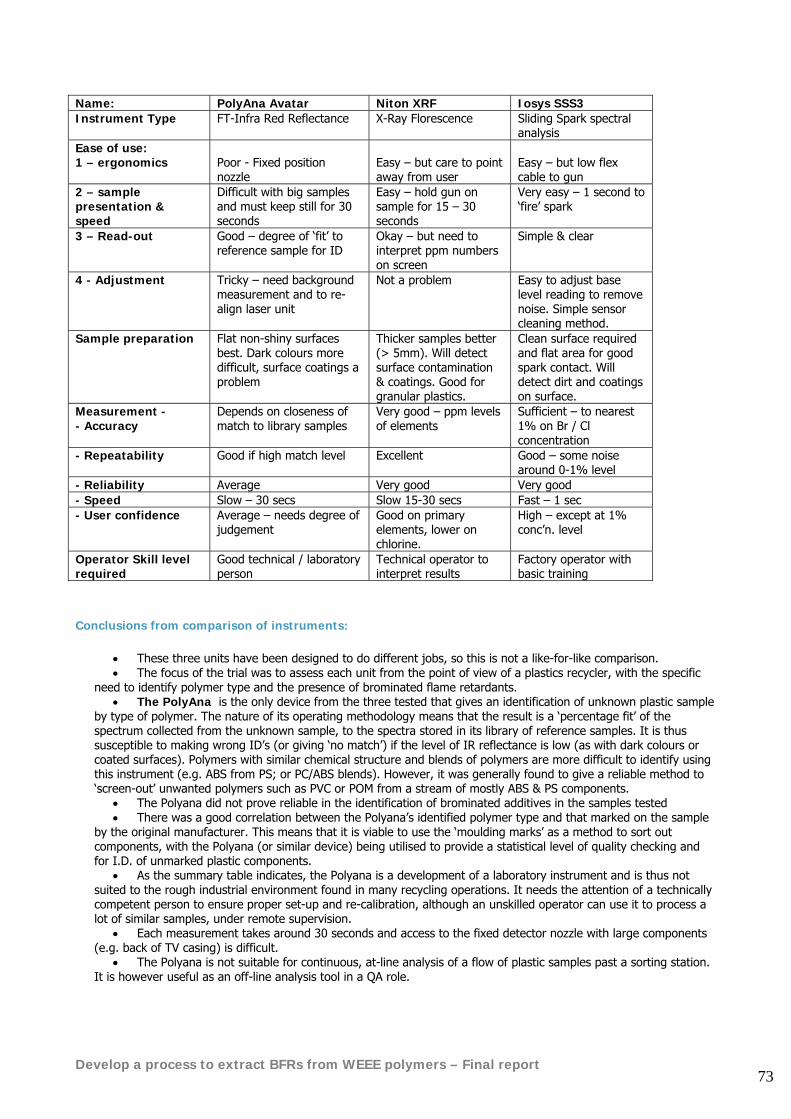
Develop a process to extract BFRs from WEEE polymers – Final report 73
Name: PolyAna Avatar Niton XRF Iosys SSS3 Instrument Type FT-Infra Red Reflectance X-Ray Florescence Sliding Spark spectral
analysis Ease of use: 1 – ergonomics
Poor - Fixed position nozzle
Easy – but care to point away from user
Easy – but low flex cable to gun
2 – sample presentation & speed
Difficult with big samples and must keep still for 30 seconds
Easy – hold gun on sample for 15 – 30 seconds
Very easy – 1 second to ‘fire’ spark
3 – Read-out Good – degree of ‘fit’ to reference sample for ID
Okay – but need to interpret ppm numbers on screen
Simple & clear
4 - Adjustment Tricky – need background measurement and to re-align laser unit
Not a problem Easy to adjust base level reading to remove noise. Simple sensor cleaning method.
Sample preparation Flat non-shiny surfaces best. Dark colours more difficult, surface coatings a problem
Thicker samples better (> 5mm). Will detect surface contamination & coatings. Good for granular plastics.
Clean surface required and flat area for good spark contact. Will detect dirt and coatings on surface.
Measurement - - Accuracy
Depends on closeness of match to library samples
Very good – ppm levels of elements
Sufficient – to nearest 1% on Br / Cl concentration
- Repeatability Good if high match level Excellent Good – some noise around 0-1% level
- Reliability Average Very good Very good - Speed Slow – 30 secs Slow 15-30 secs Fast – 1 sec - User confidence Average – needs degree of
judgement Good on primary elements, lower on chlorine.
High – except at 1% conc’n. level
Operator Skill level required
Good technical / laboratory person
Technical operator to interpret results
Factory operator with basic training
Conclusions from comparison of instruments:
• These three units have been designed to do different jobs, so this is not a like-for-like comparison. • The focus of the trial was to assess each unit from the point of view of a plastics recycler, with the specific
need to identify polymer type and the presence of brominated flame retardants. • The PolyAna is the only device from the three tested that gives an identification of unknown plastic sample
by type of polymer. The nature of its operating methodology means that the result is a ‘percentage fit’ of the spectrum collected from the unknown sample, to the spectra stored in its library of reference samples. It is thus susceptible to making wrong ID’s (or giving ‘no match’) if the level of IR reflectance is low (as with dark colours or coated surfaces). Polymers with similar chemical structure and blends of polymers are more difficult to identify using this instrument (e.g. ABS from PS; or PC/ABS blends). However, it was generally found to give a reliable method to ‘screen-out’ unwanted polymers such as PVC or POM from a stream of mostly ABS & PS components.
• The Polyana did not prove reliable in the identification of brominated additives in the samples tested • There was a good correlation between the Polyana’s identified polymer type and that marked on the sample
by the original manufacturer. This means that it is viable to use the ‘moulding marks’ as a method to sort out components, with the Polyana (or similar device) being utilised to provide a statistical level of quality checking and for I.D. of unmarked plastic components.
• As the summary table indicates, the Polyana is a development of a laboratory instrument and is thus not suited to the rough industrial environment found in many recycling operations. It needs the attention of a technically competent person to ensure proper set-up and re-calibration, although an unskilled operator can use it to process a lot of similar samples, under remote supervision.
• Each measurement takes around 30 seconds and access to the fixed detector nozzle with large components (e.g. back of TV casing) is difficult.
• The Polyana is not suitable for continuous, at-line analysis of a flow of plastic samples past a sorting station. It is however useful as an off-line analysis tool in a QA role.
Develop a process to extract BFRs from WEEE polymers – Final report 74
• The NITON XRF unit has been designed for use in a rugged environment and it is fully portable with no power cable required in use.
• The claimed ‘plastics ID’ software only uses detection of a high chlorine content to infer that the sample is PVC. No other polymer-type ID is possible. It detects a range of specified elements from the periodic table for atomic number of 13 and above (so C-H-O molecular substances such as plastics are not detected).
• It is a very accurate method that gives quantitative measurement of the important additives throughout a depth of approx 10mm into the sample. So cadmium, lead, titanium, antinomy, chromium, bromine, chlorine, etc can all be assessed accurately. Levels of a few ppm can be measured in around 15 – 30 seconds per reading.
• This instrument is better suited for use in a ‘policing’ role for the detection of RoHS banned substances and other unwanted additives at a manufacturer’s goods-in warehouse. It could also be easily taken on supplier QC visits to randomly inspect components or even bulk raw materials for unwanted additive content.
• Slow speed of measurement makes it not suitable for rapid on-line testing of a continuous flow of samples.
• Iosys SSS3 Sliding spark detector – this simple, low-cost machine does one job very well. • The no-frills design and ease-of-use make it very good for quickly sorting components by Bromine or
Chlorine content, with each measurement taking just 1-2 seconds. • It can measure bromine or chlorine in discrete components over about 20mm size but not in granular
material • It can be used at-line to screen out Br & Cl containing plastics from a stream of components. • The results for %Br on the sliding spark unit showed good correlation with the more accurate measurement
of the Niton XRF machine. • For any recycler wanting to sort brominated additive containing components from a mass of plastic parts,
this unit represents the lowest cost and simplest unit for the job. Recommendations Dismantlers of electrical equipment are likely to find that 20 – 40% by mass of their material output steams will be plastic components. Most of that mass will be concentrated in the larger plastic moulded parts (e.g. TV rear casing; printer cover; photocopier paper-tray). Value can be added to that mixed stream of polymer components by good sorting techniques to stream the material into groups of known plastic types. As few as 4 different polymer types will cover the majority of plastic found within each of the main streams of WEEE (e.g. PS; ABS; PC; ‘other’ for IT plastic parts). In many cases the use of the ‘moulding mark’ can be reliably used to sort by polymer type. However the marking of components for brominated additives has been found to be very unreliable, with either no indication of flame retardant being given or a ‘XX-FR’ code used that relates to a non-halogenated flame retardant compound. The value and range of re-use applications for recycled polymer can also be increased by thorough separation and removal of the brominated (and chlorinated) additives. This sorting process demands rapid and simple detection techniques that can be applied in an industrial environment by low skilled operators. The SSS3 sliding spark detector offers the right mix of robustness, speed and cost to make it suitable for this task. In these trials the Infra Red spectroscopy method used to verify polymer type was able to give a close match to the ‘as marked’ polymer type on the majority of components. Differences between the ‘marked’ polymer type and the detected polymer were often due to similar IR absorbance profiles of like plastic compounds (e.g. HIPS detected for part marked as PS). The type of plastics that would definitely need to be screened out were always reliably identified (e.g. POM and PVC parts). The particular instrument used in these trials was too much of a ‘laboratory-developed’ tool to make it suitable for general industrial use. The level of operator skill, time for each reading and slow start-up made it less suited to an industrial environment. Recycling firms are likely to want higher reliability and more rugged design from an instrument costing over £20,000 UK sterling. During the course of this work programme, Axion visited the premises of IOSYS in Germany (the supplier of the SSS3 sliding spark unit). IOSYS have a full range of infra-red and sliding spark plastics identification tools that have been designed for specific industrial applications. During the machine demonstration the NIR unit was able to correctly identify a set of known polymer samples and reliably pick out those that contained BFR additives. The machine that offers a combined NIR and Sliding spark detector in one unit (the Mirospark) should be able to do all the identification of polymer type and additive sorting tasks that a plastics recycler is likely to need. This unit costs around €25,000 (approx £17k) and was seen to give rapid and accurate results.
Develop a process to extract BFRs from WEEE polymers – Final report 75
For rapid on-line sorting of polymer components IOSYS have developed a suspended unit called ‘Siroline’ that focuses a beam of IR light onto a work-top or conveyor. Any piece of plastic placed in the ‘pool of light’ is rapidly identified and indicated by a row of LED lamps marked with the polymer type. This enables rapid, hands-free polymer sorting and could easily be linked to an automated plastic sorting mechanism. It must be noted that a one-off demonstration during a single day visit does not give the same level of in-use assessment that has been possible with the practical trials of the other instruments. Other instruments tested :
• Tribopen – ( www.soton.ac.uk/~wolfson ) A simple hand-held instrument that uses differential charging between the sensor head and the test sample, caused when the ‘pen’ is drawn across the sample surface. A red or green indicator light tells the user if the test sample is above or below the sensor head material in the triboelectric series. This instrument has been used in practical trials at the Hampshire Natural Resources Trust pilot WEEE demanufacturing project and has demonstrated that it can distinguish between PVC and other polymer types.
• RF Sensors – (www.oxfordrfsensors.com ) uses attenuation of radio frequency as the basis to differentiate
materials. Await full results from Oxford RF Sensors Ltd, although early indications are that polymer type can be identified. Some success has also been shown in differentiating between BFR and non-BFR polymer compounds. This is an early stage development, that is a long way from a commercial application. There may be fundamental problems with obtaining adequate penetration of RF signals into polymer samples.
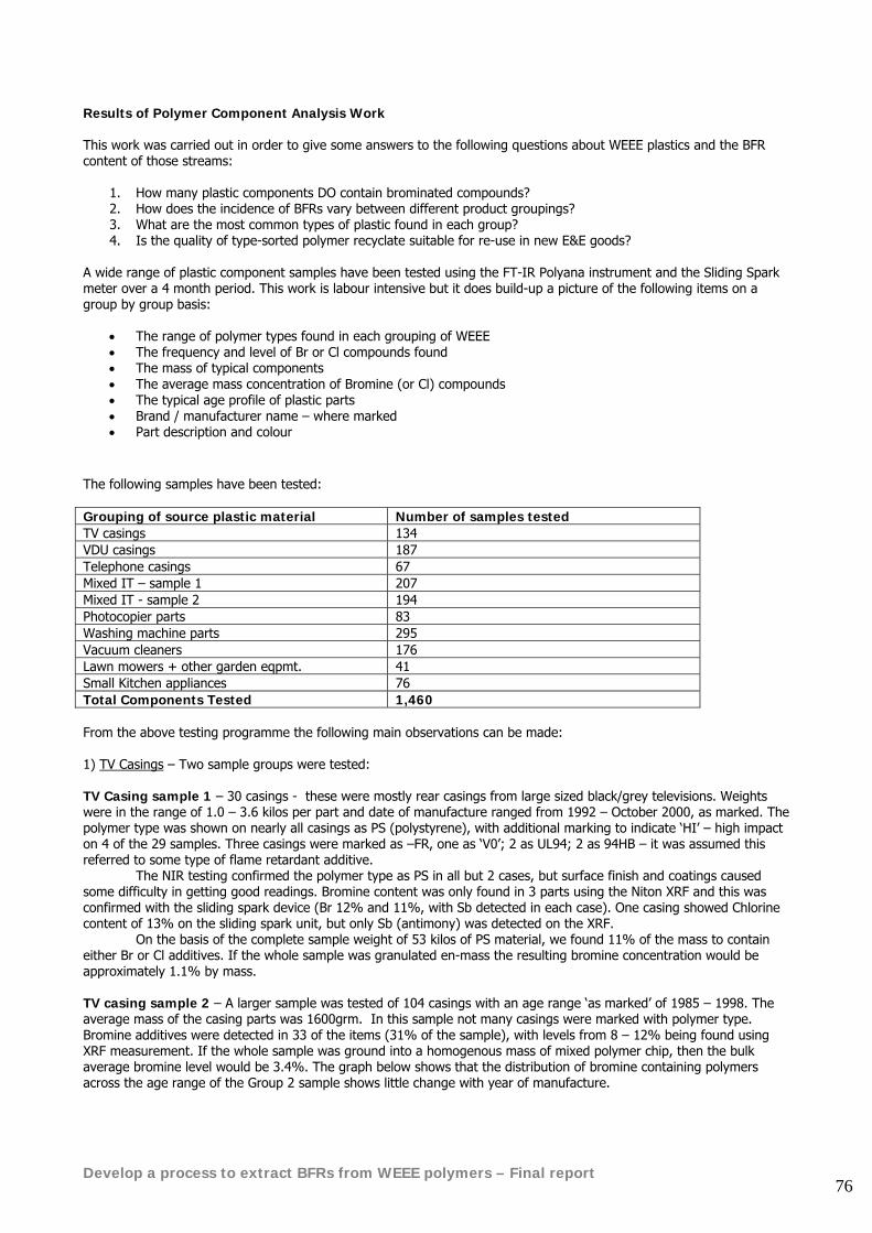
Develop a process to extract BFRs from WEEE polymers – Final report 76
Results of Polymer Component Analysis Work This work was carried out in order to give some answers to the following questions about WEEE plastics and the BFR content of those streams:
1. How many plastic components DO contain brominated compounds? 2. How does the incidence of BFRs vary between different product groupings? 3. What are the most common types of plastic found in each group? 4. Is the quality of type-sorted polymer recyclate suitable for re-use in new E&E goods?
A wide range of plastic component samples have been tested using the FT-IR Polyana instrument and the Sliding Spark meter over a 4 month period. This work is labour intensive but it does build-up a picture of the following items on a group by group basis:
• The range of polymer types found in each grouping of WEEE • The frequency and level of Br or Cl compounds found • The mass of typical components • The average mass concentration of Bromine (or Cl) compounds • The typical age profile of plastic parts • Brand / manufacturer name – where marked • Part description and colour
The following samples have been tested: Grouping of source plastic material Number of samples tested TV casings 134 VDU casings 187 Telephone casings 67 Mixed IT – sample 1 207 Mixed IT - sample 2 194 Photocopier parts 83 Washing machine parts 295 Vacuum cleaners 176 Lawn mowers + other garden eqpmt. 41 Small Kitchen appliances 76 Total Components Tested 1,460 From the above testing programme the following main observations can be made: 1) TV Casings – Two sample groups were tested: TV Casing sample 1 – 30 casings - these were mostly rear casings from large sized black/grey televisions. Weights were in the range of 1.0 – 3.6 kilos per part and date of manufacture ranged from 1992 – October 2000, as marked. The polymer type was shown on nearly all casings as PS (polystyrene), with additional marking to indicate ‘HI’ – high impact on 4 of the 29 samples. Three casings were marked as –FR, one as ‘V0’; 2 as UL94; 2 as 94HB – it was assumed this referred to some type of flame retardant additive. The NIR testing confirmed the polymer type as PS in all but 2 cases, but surface finish and coatings caused some difficulty in getting good readings. Bromine content was only found in 3 parts using the Niton XRF and this was confirmed with the sliding spark device (Br 12% and 11%, with Sb detected in each case). One casing showed Chlorine content of 13% on the sliding spark unit, but only Sb (antimony) was detected on the XRF. On the basis of the complete sample weight of 53 kilos of PS material, we found 11% of the mass to contain either Br or Cl additives. If the whole sample was granulated en-mass the resulting bromine concentration would be approximately 1.1% by mass. TV casing sample 2 – A larger sample was tested of 104 casings with an age range ‘as marked’ of 1985 – 1998. The average mass of the casing parts was 1600grm. In this sample not many casings were marked with polymer type. Bromine additives were detected in 33 of the items (31% of the sample), with levels from 8 – 12% being found using XRF measurement. If the whole sample was ground into a homogenous mass of mixed polymer chip, then the bulk average bromine level would be 3.4%. The graph below shows that the distribution of bromine containing polymers across the age range of the Group 2 sample shows little change with year of manufacture.
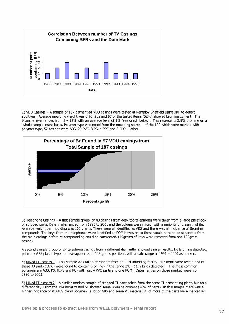
Develop a process to extract BFRs from WEEE polymers – Final report 77
Correlation Between number of TV Casings Containing BFRs and the Date Mark
01234
1985 1987 1988 1989 1990 1991 1992 1993 1994 1998
Date
Num
ber o
f par
ts
cont
aini
ng B
FR
2) VDU Casings – A sample of 187 dismantled VDU casings were tested at Remploy Sheffield using XRF to detect additives. Average moulding weight was 0.96 kilos and 97 of the tested items (52%) showed bromine content. The bromine level ranged from 2 – 18% with an average level of 9% (see graph below). This represents 3.9% bromine on a ‘whole sample’ mass basis. Polymer type was noted from the moulding stamp – of the 100 which were marked with polymer type, 52 casings were ABS, 20 PVC, 8 PS, 4 PPE and 3 PPO + other.
Percentage of Br Found in 97 VDU casings from Total Sample of 187 casings
0% 5% 10% 15% 20% 25%
Sam
ple
Percentage Br
3) Telephone Casings – A first sample group of 40 casings from desk-top telephones were taken from a large pallet-box of stripped parts. Date marks ranged from 1993 to 2001 and the colours were mixed, with a majority of cream / white. Average weight per moulding was 100 grams. These were all identified as ABS and there was nil incidence of Bromine compounds. The keys from the telephones were identified as POM however, so these would need to be separated from the main casings before re-compounding could be considered. (40grams of keys were removed from one 100gram casing). A second sample group of 27 telephone casings from a different dismantler showed similar results. No Bromine detected, primarily ABS plastic type and average mass of 145 grams per item, with a date range of 1991 – 2000 as marked. 4) Mixed IT Plastics 1 – This sample was taken at random from an IT dismantling facility. 207 items were tested and of these 33 parts (16%) were found to contain Bromine (in the range 2% - 11% Br as detected). The most common polymers are ABS, PS, HIPS and PC (with just 4 PVC parts and one POM). Dates ranges on those marked were from 1993 to 2003. 5) Mixed IT plastics 2 – A similar random sample of stripped IT parts taken from the same IT dismantling plant, but on a different day. From the 194 items tested 51 showed some Bromine content (26% of parts). In this sample there was a higher incidence of PC/ABS blend polymers, a lot of ABS and some PC material. A lot more of the parts were marked as
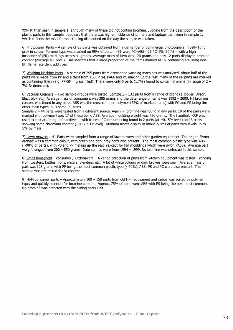
Develop a process to extract BFRs from WEEE polymers – Final report 78
‘XX-FR’ than seen in sample 1, although many of these did not contain bromine. Judging from the description of the plastic parts in this sample it appears that there was higher incidence of printers and laptops than seen in sample 1, which reflects the mix of product being dismantled on the day the sample was taken. 6) Photocopier Parts – A sample of 83 parts was obtained from a dismantler of commercial photocopiers, mostly light grey in colour. Polymer type was marked on 95% of parts :– 31 were PC+ABS ; 26 PC+PS; 20 PS – with a high incidence of (FR) markings across all grades. Average mass of item was 170 grams and only 12 parts displayed bromine content (average 4% level). This indicates that a large proportion of the items marked as FR containing are using non-Bfr flame retardant additives. 7) Washing Machine Parts – A sample of 295 parts from dismantled washing machines was analysed. About half of the parts were made from PP and a third from ABS. POM, PA66 and PC making up the rest. Many of the PP parts are marked as containing fillers (e.g. PP-GF = glass filled). There were only 5 parts (1.7%) found to contain Bromine (in range of 2 – 7% Br detected). 6) Vacuum Cleaners – Two sample groups were tested. Sample 1 – 132 parts from a range of brands (Hoover, Dyson, Electrolux etc). Average mass of component was 385 grams and the date range of items was 1992 – 2000. Nil bromine content was found in any parts. ABS was the most common polymer (72% of marked items) with PC and PS being the other main types, plus some PP items. Sample 2 – 44 parts were tested from a different source. Again nil bromine was found in any parts. 18 of the parts were marked with polymer type, 17 of these being ABS. Average moulding weight was 720 grams. The handheld XRF was used to look at a range of additives – with traces of Cadmium being found in 2 parts (at ~0.15% level) and 3 parts showing some chromium content (~0.17% Cr level). Titanium traces display in about 2/3rds of parts with levels up to 5% by mass. 7) Lawn mowers – 41 Parts were sampled from a range of lawnmowers and other garden equipment. The bright ‘Flymo orange’ was a common colour, with green and dark grey parts also present. The most common plastic type was ABS (~90% of parts), with PS and PP making up the rest (except for fan mouldings which were nylon PA66). Average part weight ranged from 200 – 550 grams. Date stamps were from 1994 – 1999. No bromine was detected in this sample. 8) Small household – consumer / kitchenware – A varied collection of parts from kitchen equipment was tested – ranging from toasters, kettles, irons, mixers, blenders, etc. A lot of white colours or dark browns were seen. Average mass of part was 125 grams with PP being the most common plastic type (~70%). ABS; PS and PC were also present. This sample was not tested for Br content. 9) Hi-Fi consumer parts – Approximately 100 – 150 parts from old Hi-fi equipment and radios was sorted by polymer type, and quickly scanned for bromine content. Approx. 75% of parts were ABS with PS being the next most common. No bromine was detected with the sliding spark unit.
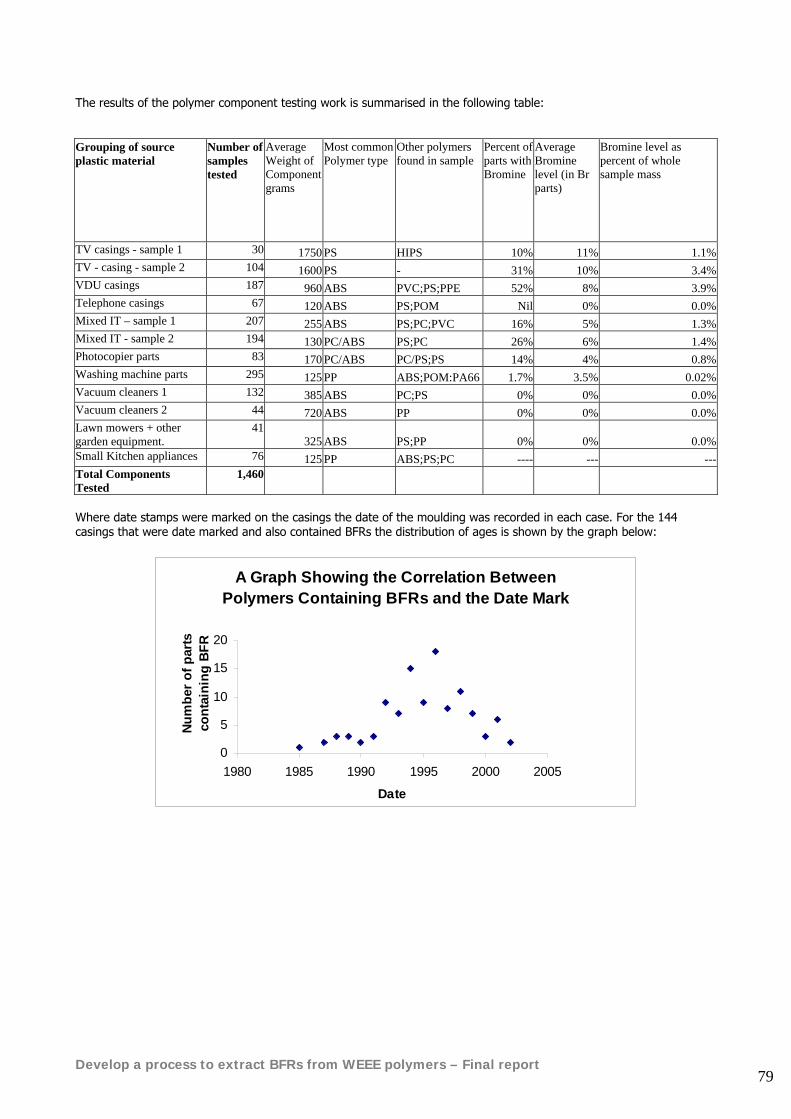
Develop a process to extract BFRs from WEEE polymers – Final report 79
The results of the polymer component testing work is summarised in the following table: Grouping of source plastic material
Number of samples tested
Average Weight of Component grams
Most common Polymer type
Other polymers found in sample
Percent of parts with Bromine
Average Bromine level (in Br parts)
Bromine level as percent of whole sample mass
TV casings - sample 1 30 1750 PS HIPS 10% 11% 1.1%TV - casing - sample 2 104 1600 PS - 31% 10% 3.4%VDU casings 187 960 ABS PVC;PS;PPE 52% 8% 3.9%Telephone casings 67 120 ABS PS;POM Nil 0% 0.0%Mixed IT – sample 1 207 255 ABS PS;PC;PVC 16% 5% 1.3%Mixed IT - sample 2 194 130 PC/ABS PS;PC 26% 6% 1.4%Photocopier parts 83 170 PC/ABS PC/PS;PS 14% 4% 0.8%Washing machine parts 295 125 PP ABS;POM:PA66 1.7% 3.5% 0.02%Vacuum cleaners 1 132 385 ABS PC;PS 0% 0% 0.0%Vacuum cleaners 2 44 720 ABS PP 0% 0% 0.0%Lawn mowers + other garden equipment.
41 325 ABS PS;PP 0% 0% 0.0%
Small Kitchen appliances 76 125 PP ABS;PS;PC ---- --- ---Total Components Tested
1,460
Where date stamps were marked on the casings the date of the moulding was recorded in each case. For the 144 casings that were date marked and also contained BFRs the distribution of ages is shown by the graph below:
A Graph Showing the Correlation Between Polymers Containing BFRs and the Date Mark
0
5
10
15
20
1980 1985 1990 1995 2000 2005
Date
Num
ber o
f par
ts
cont
aini
ng B
FR
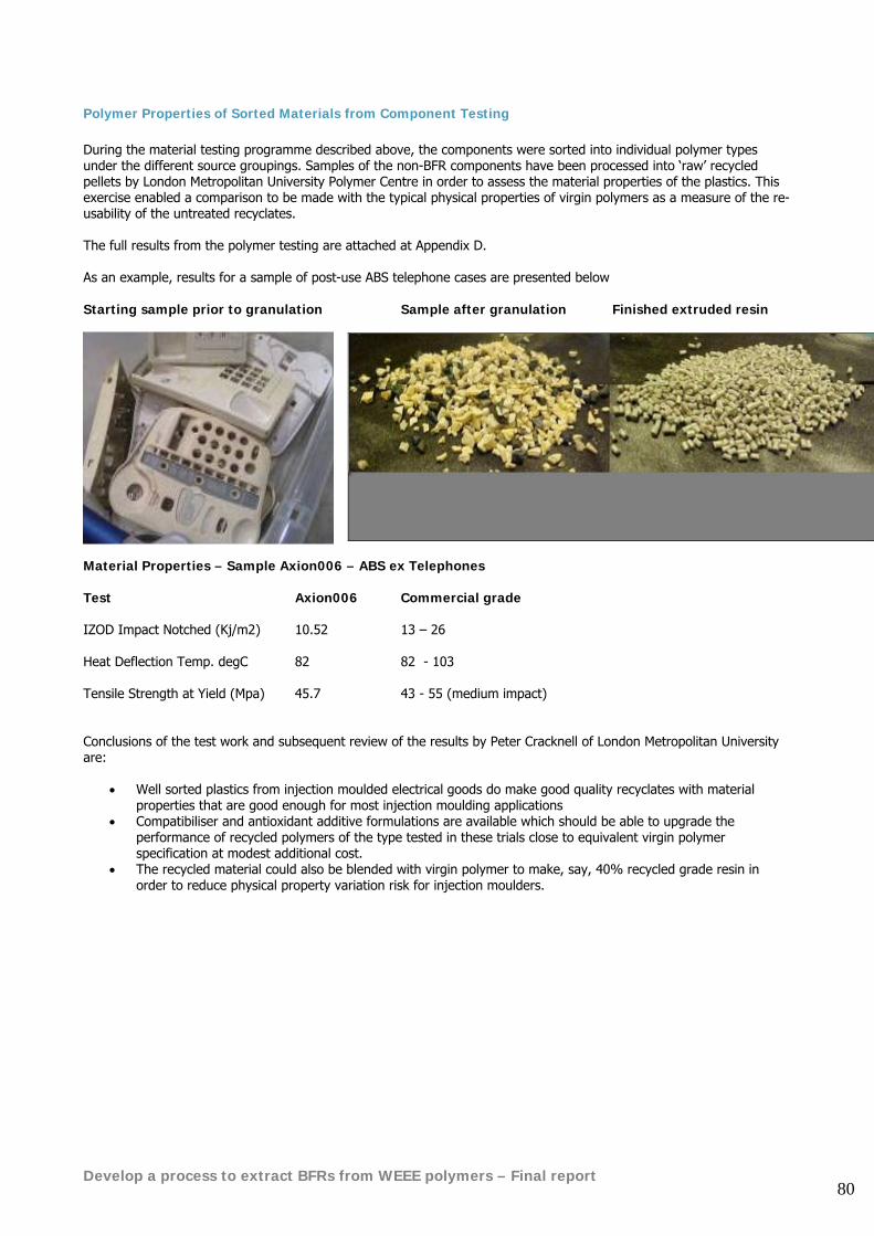
Develop a process to extract BFRs from WEEE polymers – Final report 80
Polymer Properties of Sorted Materials from Component Testing During the material testing programme described above, the components were sorted into individual polymer types under the different source groupings. Samples of the non-BFR components have been processed into ‘raw’ recycled pellets by London Metropolitan University Polymer Centre in order to assess the material properties of the plastics. This exercise enabled a comparison to be made with the typical physical properties of virgin polymers as a measure of the re-usability of the untreated recyclates. The full results from the polymer testing are attached at Appendix D. As an example, results for a sample of post-use ABS telephone cases are presented below Starting sample prior to granulation Sample after granulation Finished extruded resin
Material Properties – Sample Axion006 – ABS ex Telephones Test Axion006 Commercial grade IZOD Impact Notched (Kj/m2) 10.52 13 – 26 Heat Deflection Temp. degC 82 82 - 103 Tensile Strength at Yield (Mpa) 45.7 43 - 55 (medium impact) Conclusions of the test work and subsequent review of the results by Peter Cracknell of London Metropolitan University are:
• Well sorted plastics from injection moulded electrical goods do make good quality recyclates with material properties that are good enough for most injection moulding applications
• Compatibiliser and antioxidant additive formulations are available which should be able to upgrade the performance of recycled polymers of the type tested in these trials close to equivalent virgin polymer specification at modest additional cost.
• The recycled material could also be blended with virgin polymer to make, say, 40% recycled grade resin in order to reduce physical property variation risk for injection moulders.
Develop a process to extract BFRs from WEEE polymers – Final report 81
12.2. Bulk separation techniques A large sample of 3 tonnes of mixed plastic from shredded post-consumer household WEEE was obtained from a leading UK shredder and metal recycling company. It was not possible to make any analysis of the mix of items that had generated this plastic sample, other than from a visual impression of the infeed WEEE ‘mountain’:
Typical household WEEE – prior to shredding and metal recovery
The above infeed WEEE produced plastic that appears as follows, after the vast majority of the ferrous and non-ferrous metal has been extracted by large scale processing. This material would represent a large fraction of the infeed to any WEEE plastics sorting plant (along with plastic from fridge recyclers and bulk shredded IT plastics).
Example of plastic pieces ex shredder & post metal removal
In order to prepare this material for a range of bulk separation trials, it was further shredded down to a particle size of 20mm. The material was then passed over a combined rare earth and eddy current machine (Master Magnets Ltd – www.mastermagnets.co.uk ) in order to check for any metals that may have been liberated by the shredding, there was virtually nil metal in the sample. Some of the above sample was further reduced down to 5-8mm granule chips to be sent off for various separation trials.
Develop a process to extract BFRs from WEEE polymers – Final report 82
The following set of separation trials were carried out in order to determine which was likely to be most suitable for :
• The separation of bromine containing polymers from the bulk • The sorting of the primary polymer types within the sample mix • Removal of contaminants and minor plastic fractions • Producing a high yield of commercially viable pure plastic
List of Processes in Bulk Separation Trial
• PHB Holland – Commercial scale process used for separation of plastics from refrigerators and other mixed stream.
• Deltex Pro - Jigging Rig for liquid phase density separation, full-scale plant unit (at Recycling Avenue, Holland)
• Axsia Mozley – Hydrocyclones for liquid phase density separation • Titech Autosort – commercial scale NIR automatic sorting machine • Hamos – Triboelectric separation machine, full-scale unit. • Sortex Optical colour sorting equipment – short test • X-Ray Transmission unit at T U Delft
For the purposes of this report, a summary of these trials is presented in a tabular format below.
Develop a process to extract BFRs from WEEE polymers – Final report 83
Process Developed by Outline description Trial Size Summary Results Full-scale, multi-unit commercial process
PHB (Envirotec) Waalwijk, Holland
Series of size reduction, dust removal, liquid phase separation and final refining unit operations developed over several years. Claims to remove heavier Bfr plastics.
1450 kilos of 20mm mixed shred
Produced high yield (>55%) of clean, dry 5mm granulate product – ABS/PS (97.6% purity) with low bromine (0.03%), from feedstock of average 0.14% Br. Heavies product contains 0.65% Br; floats product – was 78% PP/PE at 0.04%Br
Water Jigging Rig – Deltex Pro
Recycling Avenue, TU Delft, Holland
Three-way density split of infeed plastics created in water tank by means of a pulsed bed of fixed density spheres, suspended on mesh. Heavy fraction must pass down through ‘jigging’ bed of spheres, middle fraction ‘sinks’ in water, but ‘floats’ on spheres of 1.1 density.
250 kilos Gave 60% yield of ABS/PS rich (97% purity) product with low Br at 0.07%. Heavies fraction was 1.8% Br, floats fraction 0.037% Br. Floats was mixed with 45% PS in PP/PE mix due to poor wetting at surface sink/float point.
Water Hydrocyclones
Axsia Mozley, Gloucester UK
Full-scale test rig used to demonstrate 3 stage separation of input material to deliver 3 density fractions. Dry sieving was used to remove around 20% fines and dust from the feed sample.
100 kilos High throughput of liquid gives dry solids feed-rate equal to 3.7 tonne/hr. This was split into 86% ABS/PS rich fraction; 12% PP/PE rich; rest heavies >1.1 SG.
NIR auto-sorter machine
Titech ‘Polysort’ detect / eject system
Full scale machine fed with 20mm nominal sized pieces. NIR reflectance used to sort by polymer type – some limitations with dark colours.
60 kilos Poor separation achieved due to high proportion of coloured components in feed material
Triboelectric sorting machine
Hamos GmBh Penzberg Germany
Particles of plastic are charged by vigorous vibration in a metal chamber. These then pass along a belt to fall through a high voltage electric field. Gives 3 way split of +ve, uncharged and –ve particles.
5 x 10kg samples mixed plastics.
Not able to generate a significant separation with 4 of the samples. One sample did give an 80/20 concentration of material – Dark colour HIPS+BFR mixed with light ABS material, but not a pure split.
Optical Colour Sorting
Sortex Ltd, London
Rapid image analysis in visual light range used for high speed sorting of falling cascade of small particles (e.g. rice grains).
2 x 10 kilo samples mixed colours
One sample of ABS from IT which was approx 30% dark/blue granules mixed with cream colour, was sorted to 99.99% purity of light in single pass at 2 tph. Telephone ABS mixed colours with light single pass gave 98% pure light; 2nd pass 99.99%.
X-Ray Transmission Sorter
Tako De Jong T U Delft Holland
Normal airport X-Ray machine used with novel analysis software to measure transmission of X-Rays through sample pieces at two energy levels. Enables identification of material by average atomic number and presence of contaminants (e.g. screw insert). Can be linked to full-scale sorting system at commercial scale.
2 x 10 kilo samples. One post consumer; one shredded IT plastic.
Laboratory rig used to demonstrate the analysis only, not seen linked to auto sort air-jets. Impressive ability to rapidly compare transmission level to a reference material and produce groupings of individual pieces on a graph, linked to the different polymer types or additive content. Software can be programmed to perform a range of sort criteria depending upon required output. (e.g. pick ABS+BFR from normal ABS etc).
Develop a process to extract BFRs from WEEE polymers – Final report 84
12.3. Observations and conclusions from the bulk trial programme
• Density separation DOES appear to remove brominated plastic compounds from a bulk shredded sample. • By careful selection of the density split point between ‘product’ and ‘heavies’, it is possible to generate a
reasonably high yield of ABS/PS polymer mix with average bromine content well below the RoHS maximum allowed concentration of 0.1%. In these trials, input material of mixed post-consumer WEEE plastic with 0.14% average bromine content was reduced to a ‘product’ bromine level of 0.03%. The majority of the bromine containing particles being concentrated into the ‘heavies’ fraction (SG>1.1).
• In these trials the ‘reject’ heavy stream was approximately 10-15% of the infeed material tonnage. • It is this mixture of brominated styrenics, PVC, PC, POM, metal, wood, rubber and stones etc that would
become the feedstock to any chemical BFR extraction plant. This is far removed from the model ‘golden samples’ that have been used in laboratory BFR extraction tests.
• The full scale commercial process at PHB Holland gave the best performance in terms of saleable product yield, because both the PP/PE floats (SG<1.0) and the ABS/PS product (1.0<SG<1.1) were of a high purity.
• The Deltex Pro jigging rig provided a more accurate density split in the 1.0 –1.1 SG range, but did not yield a very pure floats fraction. This unit is still in the later stages of process development.
• A continuous process based upon the best of the above density separation methods could be controlled to remove just enough of the halogenated compounds by fine-tuning of the lower density split point (i.e. somewhere near 1.1SG). The concentration of bromine in the bulk product could be rapidly & accurately measured at-line using a hand-held XRF instrument, such as the NITON unit. This would enable the process to give maximum yield of ABS/PS product that still achieved the required 0.1% maximum Br concentration.
• Triboelectric separation did not appear to give a reliable basis for sorting of BFR compounds from non-BFR compounds during these tests.
• The X-Ray transmission machine offers a very specific means to sort individual pieces of BFR-plastics from non-BFR compounds. The technology is not surface dependent (unlike NIR) and can be configured to remove other unwanted additives (e,g, lead, cadmium, metal inserts) in the same pass through an automated sorting machine.
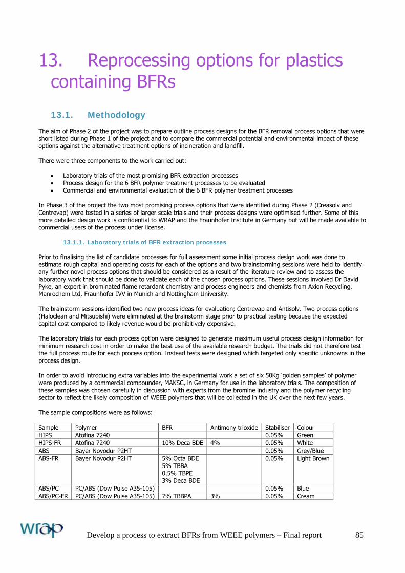
Develop a process to extract BFRs from WEEE polymers – Final report 85
13. Reprocessing options for plastics containing BFRs
13.1. Methodology The aim of Phase 2 of the project was to prepare outline process designs for the BFR removal process options that were short listed during Phase 1 of the project and to compare the commercial potential and environmental impact of these options against the alternative treatment options of incineration and landfill. There were three components to the work carried out:
• Laboratory trials of the most promising BFR extraction processes • Process design for the 6 BFR polymer treatment processes to be evaluated • Commercial and environmental evaluation of the 6 BFR polymer treatment processes
In Phase 3 of the project the two most promising process options that were identified during Phase 2 (Creasolv and Centrevap) were tested in a series of larger scale trials and their process designs were optimised further. Some of this more detailed design work is confidential to WRAP and the Fraunhofer Institute in Germany but will be made available to commercial users of the process under license.
13.1.1. Laboratory trials of BFR extraction processes Prior to finalising the list of candidate processes for full assessment some initial process design work was done to estimate rough capital and operating costs for each of the options and two brainstorming sessions were held to identify any further novel process options that should be considered as a result of the literature review and to assess the laboratory work that should be done to validate each of the chosen process options. These sessions involved Dr David Pyke, an expert in brominated flame retardant chemistry and process engineers and chemists from Axion Recycling, Manrochem Ltd, Fraunhofer IVV in Munich and Nottingham University. The brainstorm sessions identified two new process ideas for evaluation; Centrevap and Antisolv. Two process options (Haloclean and Mitsubishi) were eliminated at the brainstorm stage prior to practical testing because the expected capital cost compared to likely revenue would be prohibitively expensive. The laboratory trials for each process option were designed to generate maximum useful process design information for minimum research cost in order to make the best use of the available research budget. The trials did not therefore test the full process route for each process option. Instead tests were designed which targeted only specific unknowns in the process design. In order to avoid introducing extra variables into the experimental work a set of six 50Kg ‘golden samples’ of polymer were produced by a commercial compounder, MAKSC, in Germany for use in the laboratory trials. The composition of these samples was chosen carefully in discussion with experts from the bromine industry and the polymer recycling sector to reflect the likely composition of WEEE polymers that will be collected in the UK over the next few years. The sample compositions were as follows: Sample Polymer BFR Antimony trioxide Stabiliser Colour HIPS Atofina 7240 0.05% Green HIPS-FR Atofina 7240 10% Deca BDE 4% 0.05% White ABS Bayer Novodur P2HT 0.05% Grey/Blue ABS-FR Bayer Novodur P2HT 5% Octa BDE
5% TBBA 0.5% TBPE 3% Deca BDE
0.05% Light Brown
ABS/PC PC/ABS (Dow Pulse A35-105) 0.05% Blue ABS/PC-FR PC/ABS (Dow Pulse A35-105) 7% TBBPA 3% 0.05% Cream
Develop a process to extract BFRs from WEEE polymers – Final report 86
The compounder accidentally left antimony trioxide out of the blend for sample ABS-FR. They were not asked to repeat this batch because it was decided that it would be useful to have a sample containing bromine but free of antimony trioxide synergist for some of the polymer identification and bulk sorting trials. The homogeneity of the compounding process was checked at the laboratory of Fraunhofer IVV near Munich by testing multiple samples from each of the HIPS-FR and ABS-FR batches by X-Ray fluorescence spectroscopy for bromine and antimony trioxide. These tests confirmed good sample homogeneity as follows: HIPS-FR: 7.75 ± 0.077 % for Br and 2.37 ± 0.14 % for Sb (35 samples) ABS-FR: 11.9 ± 0.29 % for Br (10 samples)
13.1.2. Process design A flowsheet, mass balance and capital cost estimate was produced for each of the BFR polymer treatment process options selected for final evaluation. In order to ensure a valid comparison between process options the same fundamental assumptions were used for each of the process designs. The key assumptions are listed at section 6. The target performance set for the BFR extraction processes was to produce a clean polymer in granule form:
• free of all contamination below 50 micron particle size • with a maximum volatile solvent content of 1% (this is the practical limit for easy processing in unvented single
screw extruders) • containing a maximum 0.1% of the flame retardant decabromodiphenylether (decaBDE)
For the process options which destroyed the original polymer to produce either chemical feedstock or energy the target was to maximise feedstock or energy recovery and conform to UK emissions legislation.
13.1.3. Commercial and environmental evaluation Having evaluated the technical potential of the various disposal options they were compared in terms of both their commercial potential and their likely environmental impact. The commercial evaluation was conducted by compiling a business model for each disposal option at the target throughput of 10,000te/year. In each case the business model comprised financial projections for a new plant built in the UK on an existing chemical site. The financial projections included profit and loss, cash flow and balance sheet forecasts. They included a similar mix of equity and loan financing in each case. To ensure a fair comparison the same detailed assumptions were used for each option. These are listed at Section 14. Two separate environmental impact assessments were made for each option. White Young Green Consultants, an engineering consultancy with general expertise in environmental impact assessments was engaged to conduct:
a) A qualitative comparison of the environmental impacts of the different options across all impact categories b) A quantitative comparison in terms of global warming potential (CO2 production), the most relevant impact
category for polymers containing brominated flame retardants The project steering group also recommended that Dr Jaco Huisman of Huisman Recycling Research in the Netherlands should be engaged to conduct a quantitative QWERTY eco-efficiency assessment of each of the disposal options. Dr Huisman’s rigorous QWERTY analysis technique is rapidly becoming the standard across Europe for assessment of WEEE recycling processes.
The results of these analyses are presented in Section 21 of this report.
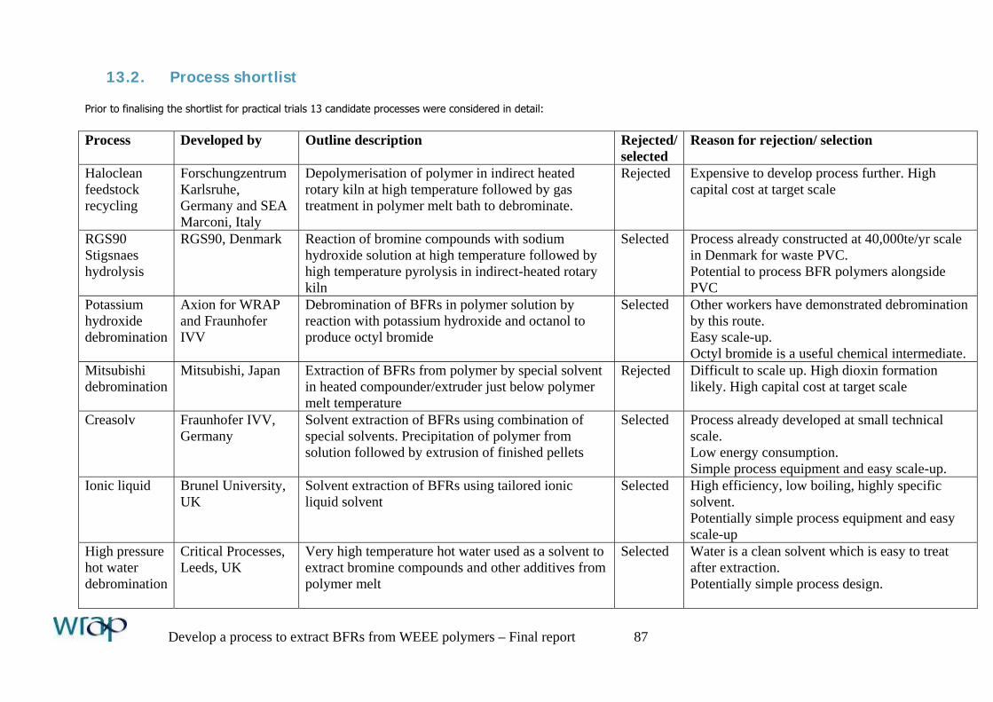
Develop a process to extract BFRs from WEEE polymers – Final report 87
13.2. Process shortlist Prior to finalising the shortlist for practical trials 13 candidate processes were considered in detail: Process Developed by Outline description Rejected/
selected Reason for rejection/ selection
Haloclean feedstock recycling
Forschungzentrum Karlsruhe, Germany and SEA Marconi, Italy
Depolymerisation of polymer in indirect heated rotary kiln at high temperature followed by gas treatment in polymer melt bath to debrominate.
Rejected Expensive to develop process further. High capital cost at target scale
RGS90 Stigsnaes hydrolysis
RGS90, Denmark Reaction of bromine compounds with sodium hydroxide solution at high temperature followed by high temperature pyrolysis in indirect-heated rotary kiln
Selected Process already constructed at 40,000te/yr scale in Denmark for waste PVC. Potential to process BFR polymers alongside PVC
Potassium hydroxide debromination
Axion for WRAP and Fraunhofer IVV
Debromination of BFRs in polymer solution by reaction with potassium hydroxide and octanol to produce octyl bromide
Selected Other workers have demonstrated debromination by this route. Easy scale-up. Octyl bromide is a useful chemical intermediate.
Mitsubishi debromination
Mitsubishi, Japan Extraction of BFRs from polymer by special solvent in heated compounder/extruder just below polymer melt temperature
Rejected Difficult to scale up. High dioxin formation likely. High capital cost at target scale
Creasolv Fraunhofer IVV, Germany
Solvent extraction of BFRs using combination of special solvents. Precipitation of polymer from solution followed by extrusion of finished pellets
Selected Process already developed at small technical scale. Low energy consumption. Simple process equipment and easy scale-up.
Ionic liquid Brunel University, UK
Solvent extraction of BFRs using tailored ionic liquid solvent
Selected High efficiency, low boiling, highly specific solvent. Potentially simple process equipment and easy scale-up
High pressure hot water debromination
Critical Processes, Leeds, UK
Very high temperature hot water used as a solvent to extract bromine compounds and other additives from polymer melt
Selected Water is a clean solvent which is easy to treat after extraction. Potentially simple process design.
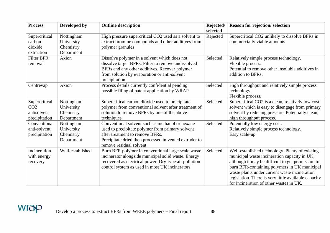
Develop a process to extract BFRs from WEEE polymers – Final report 88
Process Developed by Outline description Rejected/ selected
Reason for rejection/ selection
Supercritical carbon dioxide extraction
Nottingham University Chemistry Department
High pressure supercritical CO2 used as a solvent to extract bromine compounds and other additives from polymer granules
Rejected Supercritical CO2 unlikely to dissolve BFRs in commercially viable amounts
Filter BFR removal
Axion Dissolve polymer in a solvent which does not dissolve target BFRs. Filter to remove undissolved BFRs and any other additives. Recover polymer from solution by evaporation or anti-solvent precipitation
Selected Relatively simple process technology. Flexible process. Potential to remove other insoluble additives in addition to BFRs.
Centrevap Axion Process details currently confidential pending possible filing of patent application by WRAP
Selected High throughput and relatively simple process technology. Flexible process.
Supercritical CO2 antisolvent precipitation
Nottingham University Chemistry Department
Supercritical carbon dioxide used to precipitate polymer from conventional solvent after treatment of solution to remove BFRs by one of the above techniques.
Selected Supercritical CO2 is a clean, relatively low cost solvent which is easy to disengage from primary solvent by reducing pressure. Potentially clean, high throughput process.
Conventional anti-solvent precipitation
Nottingham University Chemistry Department
Conventional solvent such as methanol or hexane used to precipitate polymer from primary solvent after treatment to remove BFRs. Precipitate dried then processed in vented extruder to remove residual solvent
Selected Potentially low energy cost. Relatively simple process technology. Easy scale-up.
Incineration with energy recovery
Well-established Burn BFR polymer in conventional large scale waste incinerator alongside municipal solid waste. Energy recovered as electrical power. Dry-type air pollution control system as used in most UK incinerators
Selected Well-established technology. Plenty of existing municipal waste incineration capacity in UK, although it may be difficult to get permission to burn BFR-containing polymers in UK municipal waste plants under current waste incineration legislation. There is very little available capacity for incineration of other wastes in UK.
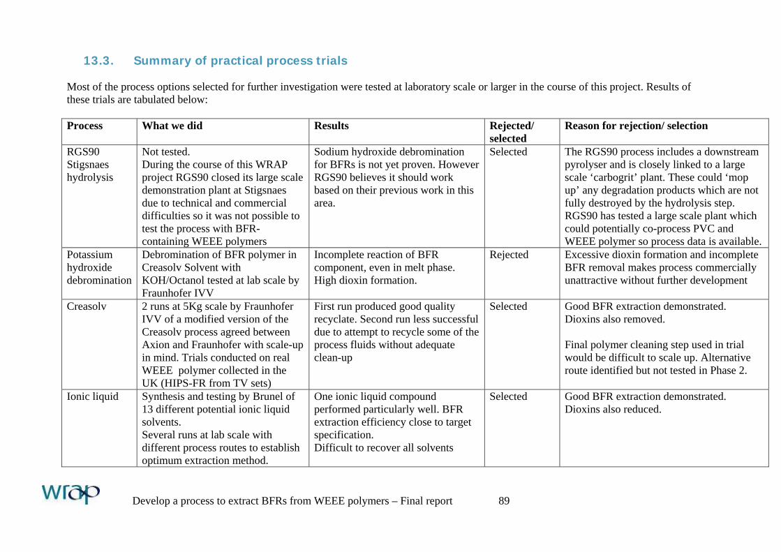
Develop a process to extract BFRs from WEEE polymers – Final report 89
13.3. Summary of practical process trials Most of the process options selected for further investigation were tested at laboratory scale or larger in the course of this project. Results of these trials are tabulated below: Process What we did Results Rejected/
selected Reason for rejection/ selection
RGS90 Stigsnaes hydrolysis
Not tested. During the course of this WRAP project RGS90 closed its large scale demonstration plant at Stigsnaes due to technical and commercial difficulties so it was not possible to test the process with BFR-containing WEEE polymers
Sodium hydroxide debromination for BFRs is not yet proven. However RGS90 believes it should work based on their previous work in this area.
Selected The RGS90 process includes a downstream pyrolyser and is closely linked to a large scale ‘carbogrit’ plant. These could ‘mop up’ any degradation products which are not fully destroyed by the hydrolysis step. RGS90 has tested a large scale plant which could potentially co-process PVC and WEEE polymer so process data is available.
Potassium hydroxide debromination
Debromination of BFR polymer in Creasolv Solvent with KOH/Octanol tested at lab scale by Fraunhofer IVV
Incomplete reaction of BFR component, even in melt phase. High dioxin formation.
Rejected Excessive dioxin formation and incomplete BFR removal makes process commercially unattractive without further development
Creasolv 2 runs at 5Kg scale by Fraunhofer IVV of a modified version of the Creasolv process agreed between Axion and Fraunhofer with scale-up in mind. Trials conducted on real WEEE polymer collected in the UK (HIPS-FR from TV sets)
First run produced good quality recyclate. Second run less successful due to attempt to recycle some of the process fluids without adequate clean-up
Selected Good BFR extraction demonstrated. Dioxins also removed. Final polymer cleaning step used in trial would be difficult to scale up. Alternative route identified but not tested in Phase 2.
Ionic liquid Synthesis and testing by Brunel of 13 different potential ionic liquid solvents. Several runs at lab scale with different process routes to establish optimum extraction method.
One ionic liquid compound performed particularly well. BFR extraction efficiency close to target specification. Difficult to recover all solvents
Selected Good BFR extraction demonstrated. Dioxins also reduced.
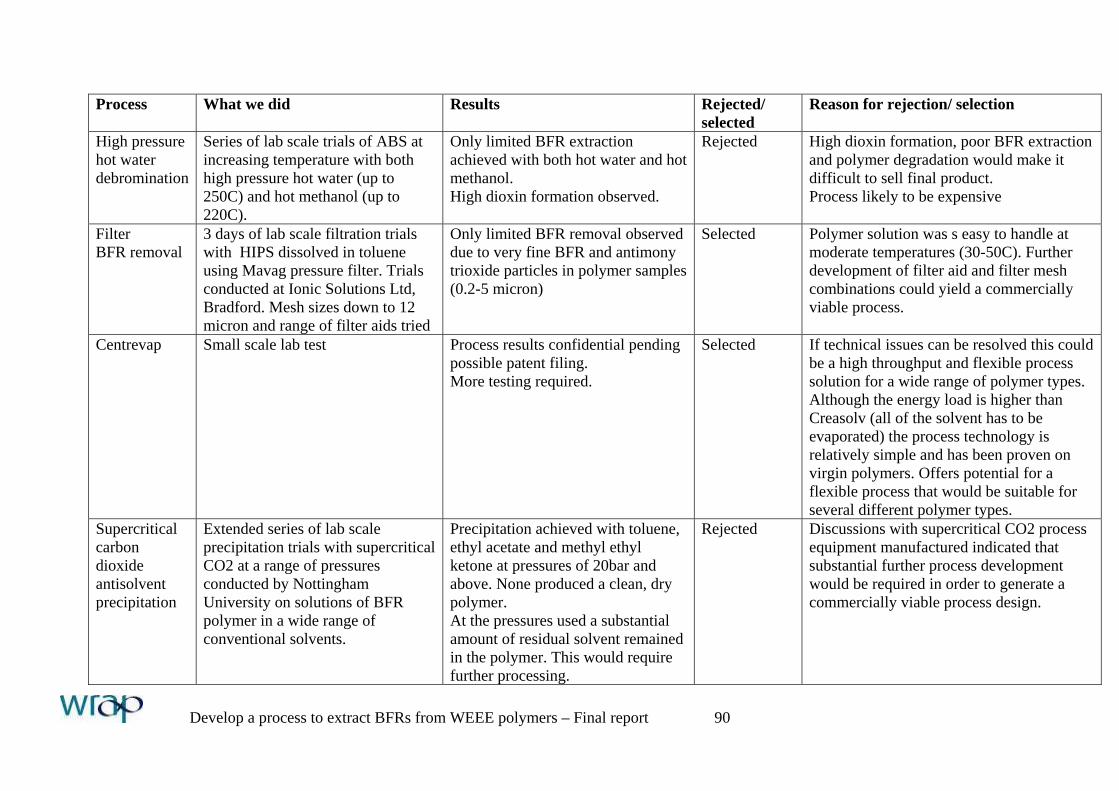
Develop a process to extract BFRs from WEEE polymers – Final report 90
Process What we did Results Rejected/
selected Reason for rejection/ selection
High pressure hot water debromination
Series of lab scale trials of ABS at increasing temperature with both high pressure hot water (up to 250C) and hot methanol (up to 220C).
Only limited BFR extraction achieved with both hot water and hot methanol. High dioxin formation observed.
Rejected High dioxin formation, poor BFR extraction and polymer degradation would make it difficult to sell final product. Process likely to be expensive
Filter BFR removal
3 days of lab scale filtration trials with HIPS dissolved in toluene using Mavag pressure filter. Trials conducted at Ionic Solutions Ltd, Bradford. Mesh sizes down to 12 micron and range of filter aids tried
Only limited BFR removal observed due to very fine BFR and antimony trioxide particles in polymer samples (0.2-5 micron)
Selected Polymer solution was s easy to handle at moderate temperatures (30-50C). Further development of filter aid and filter mesh combinations could yield a commercially viable process.
Centrevap Small scale lab test Process results confidential pending possible patent filing. More testing required.
Selected If technical issues can be resolved this could be a high throughput and flexible process solution for a wide range of polymer types. Although the energy load is higher than Creasolv (all of the solvent has to be evaporated) the process technology is relatively simple and has been proven on virgin polymers. Offers potential for a flexible process that would be suitable for several different polymer types.
Supercritical carbon dioxide antisolvent precipitation
Extended series of lab scale precipitation trials with supercritical CO2 at a range of pressures conducted by Nottingham University on solutions of BFR polymer in a wide range of conventional solvents.
Precipitation achieved with toluene, ethyl acetate and methyl ethyl ketone at pressures of 20bar and above. None produced a clean, dry polymer. At the pressures used a substantial amount of residual solvent remained in the polymer. This would require further processing.
Rejected Discussions with supercritical CO2 process equipment manufactured indicated that substantial further process development would be required in order to generate a commercially viable process design.
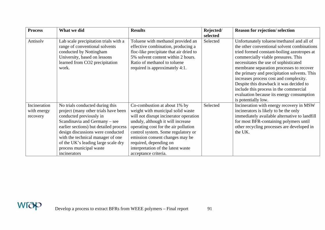
Develop a process to extract BFRs from WEEE polymers – Final report 91
Process What we did Results Rejected/
selected Reason for rejection/ selection
Antisolv Lab scale precipitation trials with a range of conventional solvents conducted by Nottingham University, based on lessons learned from CO2 precipitation work.
Toluene with methanol provided an effective combination, producing a floc-like precipitate that air dried to 5% solvent content within 2 hours. Ratio of methanol to toluene required is approximately 4:1.
Selected Unfortunately toluene/methanol and all of the other conventional solvent combinations tried formed constant-boiling azeotropes at commercially viable pressures. This necessitates the use of sophisticated membrane separation processes to recover the primary and precipitation solvents. This increases process cost and complexity. Despite this drawback it was decided to include this process in the commercial evaluation because its energy consumption is potentially low.
Incineration with energy recovery
No trials conducted during this project (many other trials have been conducted previously in Scandinavia and Germany – see earlier sections) but detailed process design discussions were conducted with the technical manager of one of the UK’s leading large scale dry process municipal waste incinerators
Co-combustion at about 1% by weight with municipal solid waste will not disrupt incinerator operation unduly, although it will increase operating cost for the air pollution control system. Some regulatory or emission consent changes may be required, depending on interpretation of the latest waste acceptance criteria.
Selected Incineration with energy recovery in MSW incinerators is likely to be the only immediately available alternative to landfill for most BFR-containing polymers until other recycling processes are developed in the UK.
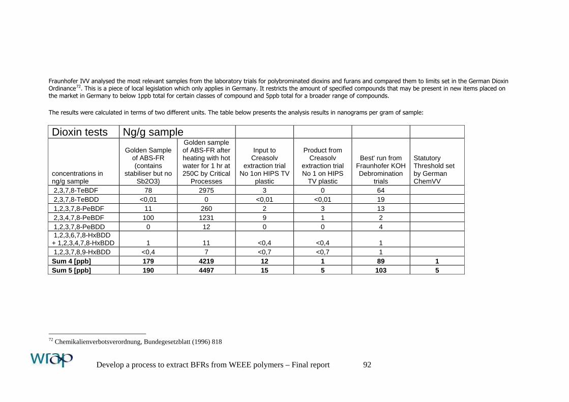
Develop a process to extract BFRs from WEEE polymers – Final report 92
Fraunhofer IVV analysed the most relevant samples from the laboratory trials for polybrominated dioxins and furans and compared them to limits set in the German Dioxin Ordinance72. This is a piece of local legislation which only applies in Germany. It restricts the amount of specified compounds that may be present in new items placed on the market in Germany to below 1ppb total for certain classes of compound and 5ppb total for a broader range of compounds. The results were calculated in terms of two different units. The table below presents the analysis results in nanograms per gram of sample: Dioxin tests Ng/g sample
concentrations in ng/g sample
Golden Sample of ABS-FR (contains
stabiliser but no Sb2O3)
Golden sample of ABS-FR after heating with hot water for 1 hr at 250C by Critical
Processes
Input to Creasolv
extraction trial No 1on HIPS TV
plastic
Product from Creasolv
extraction trial No 1 on HIPS
TV plastic
Best' run from Fraunhofer KOH Debromination
trials
Statutory Threshold set by German ChemVV
2,3,7,8-TeBDF 78 2975 3 0 64 2,3,7,8-TeBDD <0,01 0 <0,01 <0,01 19 1,2,3,7,8-PeBDF 11 260 2 3 13 2,3,4,7,8-PeBDF 100 1231 9 1 2 1,2,3,7,8-PeBDD 0 12 0 0 4 1,2,3,6,7,8-HxBDD + 1,2,3,4,7,8-HxBDD 1 11 <0,4 <0,4 1 1,2,3,7,8,9-HxBDD <0,4 7 <0,7 <0,7 1 Sum 4 [ppb] 179 4219 12 1 89 1 Sum 5 [ppb] 190 4497 15 5 103 5
72 Chemikalienverbotsverordnung, Bundegesetzblatt (1996) 818
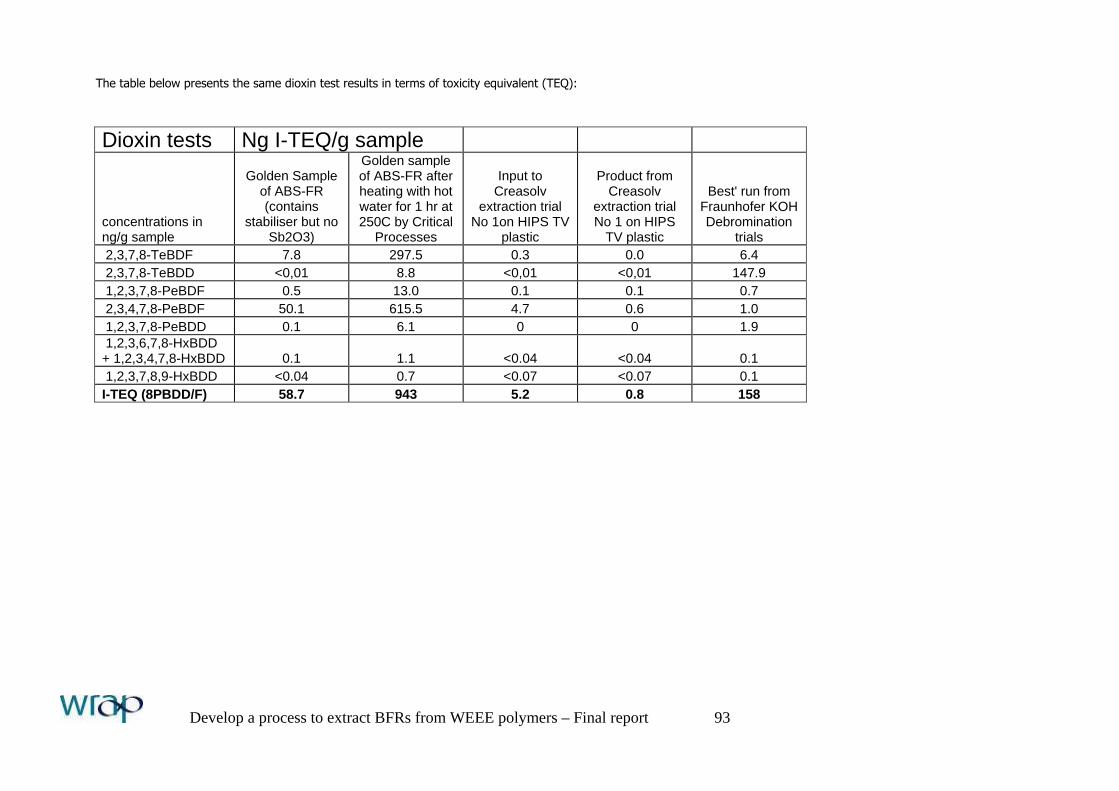
Develop a process to extract BFRs from WEEE polymers – Final report 93
The table below presents the same dioxin test results in terms of toxicity equivalent (TEQ): Dioxin tests Ng I-TEQ/g sample
concentrations in ng/g sample
Golden Sample of ABS-FR (contains
stabiliser but no Sb2O3)
Golden sample of ABS-FR after heating with hot water for 1 hr at 250C by Critical
Processes
Input to Creasolv
extraction trial No 1on HIPS TV
plastic
Product from Creasolv
extraction trial No 1 on HIPS
TV plastic
Best' run from Fraunhofer KOH Debromination
trials 2,3,7,8-TeBDF 7.8 297.5 0.3 0.0 6.4 2,3,7,8-TeBDD <0,01 8.8 <0,01 <0,01 147.9 1,2,3,7,8-PeBDF 0.5 13.0 0.1 0.1 0.7 2,3,4,7,8-PeBDF 50.1 615.5 4.7 0.6 1.0 1,2,3,7,8-PeBDD 0.1 6.1 0 0 1.9 1,2,3,6,7,8-HxBDD + 1,2,3,4,7,8-HxBDD 0.1 1.1 <0.04 <0.04 0.1 1,2,3,7,8,9-HxBDD <0.04 0.7 <0.07 <0.07 0.1 I-TEQ (8PBDD/F) 58.7 943 5.2 0.8 158
Develop a process to extract BFRs from WEEE polymers – Final report 94
14. Process design assumptions
Standard design assumptions were used to compare all of the process options that were evaluated in the course of the project in order to ensure that the comparisons were fair and realistic. These assumptions are set out below.
14.1. Commercial parameters We have assumed that Annex 2 of the WEEE Directive is implemented in the UK and therefore that BFR polymers must be treated separately. We also assume that mechanical recycling of WEEE polymers in the UK will be a cost-effective alternative to landfill. We therefore assume that mechanical recycling processors will develop who will produce separated streams or BFR-free polymer for re-use and that they will make a profit on the sale of this material. There are several polymer recycling companies in the UK and mainland Europe that are developing their business in this direction. If the WEEE Directive is enforced then these companies will not be able to sell their BFR-containing polymer for direct re-use. It will therefore have to be disposed. The cheapest disposal route in the UK is landfill- at a cost of about £45/te for bulk disposal. We have therefore assumed in our base-case evaluations of the Creasolv and Incineration with energy recovery disposal options that they will be able to attract a similar gate fee (£45/te) for BFR-containing WEEE polymers delivered to their sites. However the Centrevap process option will not remove BFRs effectively enough to achieve the targets set for this project so operators of this process option will have to compete with exporters of WEEE polymers to China. These buyers are currently paying around £100/te for sorted WEEE plastics so this is the input price assumed for the evaluation of the Centrevap process option. Detailed assumptions are: • UK economic conditions • Plant to be constructed on an existing serviced chemical site • Feedstock: Relatively clean, sorted, size-reduced BFR-containing styrenic WEEE polymers (HIPS, ABS or ABS/PC)
produced as a waste stream from several WEEE polymer mechanical recycling plants across the UK. It was assumed that the mechanical recycling plants would use sorting techniques of the type tested during this project to recover BFR-free WEEE polymers for immediate re-sale at a profit.
• Feedstock contains 10% brominated flame retardant and 10% inert additives (contamination, fillers, etc). Note that the intermediate commercial evaluations conducted for all the process options in Phase 2 assumed 2% inert content. This was raised to 10% for the final evaluations following a request from Plastics Europe.
• It is assumed that the amount of Penta BDE in the feed is negligible. Penta BDE is not generally used with the thermoplastic polymers typically recovered from WEEE.
• The BFR-containing polymers which the mechanical recycling plants would separate for treatment or disposal in accordance with Annex 2 of the WEEE Directive would attract a disposal gate fee similar to current UK landfill cost of £45/te when delivered to the BFR treatment processes. Note that an input cost of £100/te was assumed for the Centrevap option as explained above.
• Where high quality, compounded BFR-free polymers are produced from a BFR extraction process they are expected to sell for around 60% of November 2005 virgin polymer prices. This equates to a selling price assumption of £600/te for ABS and ABS/PC and £510/te for HIPS (average £560/te). Note that the Phase 2 evaluations presented in section 15.1 and in Appendix 3 used a lower polymer price assumption of 45% of June 2005 virgin polymer prices. This equated to a selling price assumption of £450/te for ABS and ABS/PC and £425/te for HIPS. The price assumption was raised in Phase 3 based on market feedback that high grade WEEE polymer recyclates will attract better prices than originally assumed because manufacturers are keen to include high quality recycled content in their products.
• Plant assets financed 40% with equity, 60% by leases and debt. Lease period 5 years, interest rate 7%. Debt period 3 years, interest rate 12%.
• Working capital financed 100% by equity. • VAT rate 17.5%. Corporation Tax rate 30%.
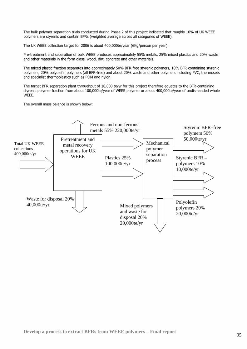
Develop a process to extract BFRs from WEEE polymers – Final report 95
The bulk polymer separation trials conducted during Phase 2 of this project indicated that roughly 10% of UK WEEE polymers are styrenic and contain BFRs (weighted average across all categories of WEEE). The UK WEEE collection target for 2006 is about 400,000te/year (6Kg/person per year). Pre-treatment and separation of bulk WEEE produces approximately 55% metals, 25% mixed plastics and 20% waste and other materials in the form glass, wood, dirt, concrete and other materials. The mixed plastic fraction separates into approximately 50% BFR-free styrenic polymers, 10% BFR-containing styrenic polymers, 20% polyolefin polymers (all BFR-free) and about 20% waste and other polymers including PVC, thermosets and specialist thermoplastics such as POM and nylon. The target BFR separation plant throughput of 10,000 te/yr for this project therefore equates to the BFR-containing styrenic polymer fraction from about 100,000te/year of WEEE polymer or about 400,000te/year of undismantled whole WEEE. The overall mass balance is shown below:
Ferrous and non-ferrous metals 55% 220,000te/yr
Pretreatment and metal recovery
operations for UK WEEE
Total UK WEEE collections 400,000te/yr
Waste for disposal 20% 40,000te/yr
Plastics 25% 100,000te/yr
Styrenic BFR–free polymers 50% 50,000te/yr
Mechanical polymer separation process Styrenic BFR –
polymers 10% 10,000te/yr
Mixed polymers and waste for disposal 20% 20,000te/yr
Polyolefin polymers 20% 20,000te/yr
Develop a process to extract BFRs from WEEE polymers – Final report 96
14.2. Operating parameters • Plant throughput: 10,000te/year. • Plant designed for 24 hour /day, 7 day per week operation • Plant overall equipment efficiency (OEE) 80%73. • Steam cost £8/te (delivered on a cost/te basis by the site owners) • Cooling water 1.4p/te (delivered on a cost/te basis by the site owners) • Power cost £70/MWh • Fuel cost (for mobile plant) 75p/litre • Hazardous waste landfill disposal cost £80/te • Water effluent disposal cost calculated from expected effluent composition according to the standard ‘Mogden
Formula’ which is used by all water authorities in the UK to calculate trade effluent treatment charges. The disposal prices used were those charged in 2004 by United Utilities PLC, a major UK utility company.
• Process operator job cost £25,000/year – number of operators/shift varying according to process complexity • Other salaries (management, admin, laboratory, etc) in the range £23,000 to £50,000/year. Total of £153,000, the
same for all process options apart from incineration, which was costed based on discussions with incinerator operators.
73 OEE is the product of capacity utilisation, quality rate and operating time. To achieve 80% OEE a plant could operate at 93% of rated capacity, produce on-spec material for 93% of the time and run for 93% of the available operating hours each year (93%x93%x93% = 80%) . Alternatively it could run at 100% of rated capacity, produce 100% on-spec product and run for 80% of the available operating hours and achieve the same OEE (100%x100%x80% = 80%)
Develop a process to extract BFRs from WEEE polymers – Final report 97
15. Short-listed process options
As a result of the lab trials the following process options were considered for process design followed by commercial and environmental evaluation: • Creasolv • Ionic liquid extraction • Centrevap • Antisolv • RGS90 Stigsnaes • Incineration with energy recovery Outline process designs and business models were prepared for each option. The detailed analysis results for the Ionic liquid extraction, Antisolv and RGS90 Stigsnaes options are presented in Appendix 3. These options were not pursued further in Phase 3 of the project because the initial commercial and environmental evaluations during Phase 2 indicated that they would be unlikely to be commercially viable in the UK context.
15.1. Comparison of process options The commercial and environmental evaluations of the 6 most promising process options are summarised below. The table shows the results estimated in Phase 2 for the Ionic Liquid, Antisolv and RGS90 process options while the figures shown for the Creasolv, Centrevap and Incineration with energy recovery options are the revised results estimated during Phase 3 of the project. Process Yield of
usable polymer from feed
Capital cost
Solvent cost
Utility & waste treatment cost
Gate fee charged
Net product revenue
Final polymer selling price
Operating profit/ (loss) at full output
Project IRR
£m £/te feed
£/te feed £/te feed
£/te feed
£/te finished polymer
£/te feed
Creasolv 77% 11.8 12.5 67 45 479 560 226 negativeIonic Liquid
76% 5.4 210 171 45 473 560 58 negative
Centrevap 81% 6.1 6 62 -100 357 560 191 16% Antisolv 77% 9.3 87 108 45 479 560 106 negativeRGS90 nil - - - 95 - - - - Incineration with energy recovery
nil - - - 210 - - - -
The gate fee shown for the Centrevap process option is -£100/te because this process will not remove brominated flame retardents. It will therefore only be useful for producing high grade recyclate from WEEE polymers which are already BFR-free. The process operator will have to pay a positive price of around £100/te for this feed material.
Develop a process to extract BFRs from WEEE polymers – Final report 98
Note that the capital cost estimates for the Ionic Liquid and Antisolv process options were not re-estimated in Phase 3. Based on the lessons learned during more detailed design for Creasolv and Centrevap in Phase 3 it is likely that the true capital costs will be roughly double the costs shown in this table. Project internal rates of return (IRR) were not estimated for the RGS90 feedstock recycling process or the option of incineration with energy recovery because these are both existing commercial processes where the process operators were not prepared to divulge their internal operating costs. In these two cases we worked with the process operators to estimate what their gate fee would have to be for BFR-containing WEEE polymers if they were to achieve the same rate of return that they would obtain when processing their normal feed material. In the case of the RGS90 option the gate fee was lower than for its normal feed material (PVC) due to the higher hydrocarbon content of WEEE polymers. In the case of incineration with energy recovery the gate fee was considerably higher than for the normal feed of municipal solid waste (MSW). The base gate fee assumed for MSW entering an incinerator was £45/te – to compete with landfill. The reasons why the gate fee required to treat BFR-containing WEEE polymers in the UK is higher than for MSW are explained in section 19.3.
15.2. Analysis The commercial and technical analysis that was conducted at the end of Phase 2 highlighted Creasolv and Centrevap as the two most promising process options. Creasolv demonstrated good levels of BFR extraction in practical trials during phase two of the project. It had potential to achieve the proposed RoHS limit of 0.1% for Deca BDE content and the ‘Penta Directive’ requirement of 0.1% for Octa BDE with further process development. The business model for Creasolv based on these initial results demonstrated potential for attractive commercial returns at a gate fee of £45/te for the feed material. At present this gate fee is not achievable in the UK for size-reduced WEEE polymers. Exporters to China are currently paying £50-150/te for WEEE polymers containing BFRs. However if the WEEE Directive is fully implemented in the UK and separate treatment of BFR-containing polymers is mandated in accordance with Annex 2 of the directive then the export route may be closed off and this material should attract a gate fee in competition with landfill. The Centrevap process will not remove BFRs which are partly or fully soluble in solvents such as toluene, ethyl acetate, DMF, THF and dichloromethane. These include many of the target flame retardants for this project, including penta, octa and deca BDE. However the process has potential to remove many other insoluble additives and impurities efficiently and at relatively low cost. Details of the process designs and commercial analyses of the Ionic Liquid, Antisolv and RGS90 process options are attached at Appendix 3. These processes are not presented in detail in this main report because the business modelling and environmental assessment work during Phase 2 indicated that they would not be competitive with the Creasolv, Centrevap or Incineration with energy recovery disposal options. Details of the development work during Phases 2 and 3 of the Creasolv and Centrevap processes are attached at Appendix 4. Results of the large scale trials and the final process designs for the Creasolv and Centrevap processes are presented in Sections 16 and 17 below. Section 18 presents an analysis of the option of disposing BFR-containing WEEE polymers in UK waste incinerators with energy recovery. Section 21 compares the environmental performance of the process options and Section 22 compares the commercial performance of the optimised Creasolv and Centrevap process designs with the alternatives of incineration with energy recovery and landfill.
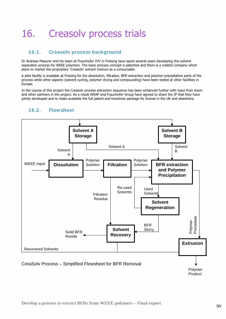
Develop a process to extract BFRs from WEEE polymers – Final report 99
16. Creasolv process trials
16.1. Creasolv process background Dr Andreas Maeurer and his team at Fraunhofer IVV in Freising have spent several years developing this solvent separation process for WEEE polymers. The basic process concept is patented and there is a related company which plans to market the proprietary ‘Creasolv’ solvent mixture as a consumable.
A pilot facility is available at Freising for the dissolution, filtration, BFR-extraction and polymer-precipitation parts of the process while other aspects (solvent cycling, polymer drying and compounding) have been tested at other facilities in Europe.
In the course of this project the Creasolv process extraction sequence has been enhanced further with input from Axion and other partners in the project. As a result WRAP and Fraunhofer Group have agreed to share the IP that they have jointly developed and to make available the full patent and knowhow package for license in the UK and elsewhere.
16.2. Flowsheet
CreaSolv Process – Simplified Flowsheet for BFR Removal
Used Solvents
Recovered Solvents
Solvent Recovery
BFR Slurry Solid BFR
Reside
Solvent Regeneration
Filtration Residue
Re-used Solvents
Solvent A Storage
Dissolution Filtration WEEE Input
Solvent A
Solvent A
Polymer Solution
Polymer Solution
Solvent B Storage
BFR extraction and Polymer Precipitation
Extrusion
Solvent B
Pol
ymer
P
reci
pita
te
Polymer Product
Develop a process to extract BFRs from WEEE polymers – Final report 100
16.3. Process description The Creasolv Process is a batch process which uses a high boiling point solvent to dissolve the feed plastic. A series of precipitation steps follow using a combination of proprietary Creasolv solvents. These reduce the bromine content in the polymer to less than 0.1%.
The BFRs are extracted into the solvents and the solvents are recovered by a proprietary process.
The main steps in the process are dissolution, filtration, a series of extractions and extrusion of the final product.
Input feed material
The input feed material to the plant consists of shredded plastic waste of approximate size between 30-50 mm. The plastic waste should be pre-sorted so that it is primarily BFR-containing HIPS and ABS.
Dissolution
Regenerated Creasolv solvent from previous batches is stored under ambient conditions in carbon steel storage tanks ready for use in the dissolution process.
A jacketed-dissolution vessel is filled with Creasolv solvent and heated via the heating jacket. The polymer is added.
At elevated temperature, the polymer and BFRs are both soluble in the hot Creasolv.
Filtration
Any undissolved polymers and other insoluble impurities are removed by filtration. A pump draws from the dissolution vessels to feed the filters. The filters are self-cleaning and will discharge the collected solids intermittently for treatment in the solvent recovery unit. The filtrate contains the dissolved polymer and all other soluble additives, while the filter residue contains the undissolved polymer, insoluble additives and inerts such as paper, fluff and metals.
BFR extraction and polymer precipitation
The filtered solution from the dissolution vessel is pumped into a solvent extraction unit. A second proprietary Creasolv solvent is added. This causes the polymer and the BFRs to separate.
The bulk of the excess solvent is removed from the debrominated polymer in a series of special extraction units. The recovered solvent mixture is pumped to store tanks and then passed to a special solvent regeneration unit.
Solvent regeneration
A novel solvent regeneration process has been developed as a result of the collaboration between WRAP and Fraunhofer IVV. This process separates the BFRs from the two Creasolv extract solvents and separates the solvents from each other ready for re-use. The detail of this part of the process is confidential to Fraunhofer IVV and WRAP.
BFRs are recovered by the solvent regeneration unit as a concentrated bromine-rich slurry. This slurry is passed to the final solvent recovery unit along with the filter residues from the first stage of the process.
Extrusion
The polymer gel particles from the extraction/ precipitation step are passed to a vacuum vented twin screw or ring extruder for removal of the remaining solvent down to below 1%. 1% is the limit required to allow subsequent processing of the polymer by injection moulders. The polymer product is cooled in a water bath and pelletized.
Additives and masterbatch can be added at this stage to modify the final polymer properties if required.
The solvents removed by venting during extrusion are returned to the solvent regeneration unit for recovery
Final solvent recovery unit
The Solvent Recovery Unit receives slurries from the filters and the solvent regeneration unit. It processes these slurries separately batch-wise and recovers almost all the solvents by heating under vacuum, resulting in a dry, free-flowing bromine-rich inert residue which is safe for disposal to landfill or may be treated further to recover bromine and antimony.
The mixed solvents that are recovered by this unit are returned to the solvent regeneration process.
A representative of the bromine and antimony industries has indicated that they would be prepared to take back the bromine and antimony residues at zero cost for use as feedstock for new products if they were separated to an adequate level of purity.
If this could be arranged it would improve the process economics by removing the need for hazardous waste disposal of the solvent recovery residues and would also improve the environmental impact performance.
Develop a process to extract BFRs from WEEE polymers – Final report 101
Fraunhofer IVV claims to have developed a method to separate the bromine and antimony components of the residue from the solvent recovery unit. The two fractions could then be recovered relatively straightforwardly by the bromine and antimony industries.
Axion has not yet been able to test the separated fractions produced by Fraunhofer IVV so the process evaluations presented in this report assume that bromine and antimony cannot be recovered for useful applications.
ENERGY USED • Hot utility requirement (Low Pressure Steam- 5 bar): 4.7 te of steam/te feed
• Cold utility requirement (Cold Water): 60.5 te/te feed
• Power (Average Draw): 208 kWh/te feed
EFFLUENTS PRODUCED
Water Effluent
None
Vapour Effluent
The extruder producing the final polymer and the final solvent recovery unit will both generate small quantities of solvent emissions to atmosphere via the vacuum system. The great majority of these emissions can be controlled by a cold trap fitted on the input side of the vac pump, particularly as the Creasolv solvents have high boiling points. Any residual emissions from the vacuum pump can be eliminated by means of a biological filter if required.
Solids
BFR leaves the solvent regeneration process as a slurry in Creasolv solvent. The solvent is recovered and recycled from the slurry by the solvent recovery unit and discharged for landfill disposal as a dry free-flowing powder.
Solid residues are also produced from the primary filter as a slurry in Creasolv solvent. This residue is also treated in the solvent recovery unit. The filter residue solids are discharged from the solvent recovery unit as a dry cake for landfill disposal.
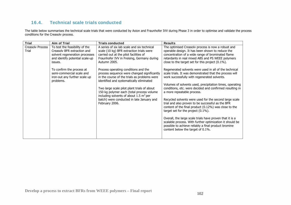
Develop a process to extract BFRs from WEEE polymers – Final report 102
16.4. Technical scale trials conducted The table below summarises the technical scale trials that were conducted by Axion and Fraunhofer IVV during Phase 3 in order to optimise and validate the process conditions for the Creasolv process. Trial Aim of Trial Trials conducted Results Creasolv Process Trial
To test the feasibility of the Creasolv BFR extraction and solvent regeneration processes and identify potential scale-up issues. To confirm the process at semi-commercial scale and iron-out any further scale up problems.
A series of six lab scale and six technical scale (10 kg) BFR extraction trials were carried out at the pilot facilities of Fraunhofer IVV in Freising, Germany during Autumn 2005. Process operating conditions and the process sequence were changed significantly in the course of the trials as problems were identified and systematically eliminated Two large scale pilot plant trials of about 150 kg polymer each (total process volume including solvents of about 1.5 m3 per batch) were conducted in late January and February 2006.
The optimised Creasolv process is now a robust and operable design. It has been shown to reduce the concentration of a wide range of brominated flame retardants in real mixed ABS and PS WEEE polymers close to the target set for this project (0.1%). Regenerated solvents were used in all of the technical scale trials. It was demonstrated that the process will work successfully with regenerated solvents. Volumes of solvents used, precipitation times, operating conditions, etc. were decided and confirmed resulting in a more repeatable process. Recycled solvents were used for the second large scale trial and also proven to be successful as the BFR content of the final product (0.12%) was close to the target set for the project (0.1%). Overall, the large scale trials have proven that it is a scalable process. With further optimization it should be possible to achieve reliably a final product bromine content below the target of 0.1%.
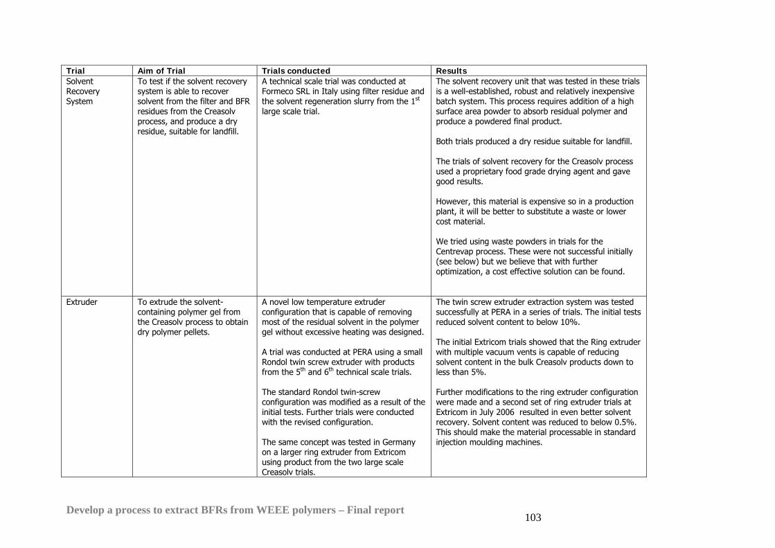
Develop a process to extract BFRs from WEEE polymers – Final report 103
Trial Aim of Trial Trials conducted Results Solvent Recovery System
To test if the solvent recovery system is able to recover solvent from the filter and BFR residues from the Creasolv process, and produce a dry residue, suitable for landfill.
A technical scale trial was conducted at Formeco SRL in Italy using filter residue and the solvent regeneration slurry from the 1st large scale trial.
The solvent recovery unit that was tested in these trials is a well-established, robust and relatively inexpensive batch system. This process requires addition of a high surface area powder to absorb residual polymer and produce a powdered final product. Both trials produced a dry residue suitable for landfill. The trials of solvent recovery for the Creasolv process used a proprietary food grade drying agent and gave good results. However, this material is expensive so in a production plant, it will be better to substitute a waste or lower cost material. We tried using waste powders in trials for the Centrevap process. These were not successful initially (see below) but we believe that with further optimization, a cost effective solution can be found.
Extruder To extrude the solvent-containing polymer gel from the Creasolv process to obtain dry polymer pellets.
A novel low temperature extruder configuration that is capable of removing most of the residual solvent in the polymer gel without excessive heating was designed. A trial was conducted at PERA using a small Rondol twin screw extruder with products from the 5th and 6th technical scale trials. The standard Rondol twin-screw configuration was modified as a result of the initial tests. Further trials were conducted with the revised configuration. The same concept was tested in Germany on a larger ring extruder from Extricom using product from the two large scale Creasolv trials.
The twin screw extruder extraction system was tested successfully at PERA in a series of trials. The initial tests reduced solvent content to below 10%. The initial Extricom trials showed that the Ring extruder with multiple vacuum vents is capable of reducing solvent content in the bulk Creasolv products down to less than 5%. Further modifications to the ring extruder configuration were made and a second set of ring extruder trials at Extricom in July 2006 resulted in even better solvent recovery. Solvent content was reduced to below 0.5%. This should make the material processable in standard injection moulding machines.
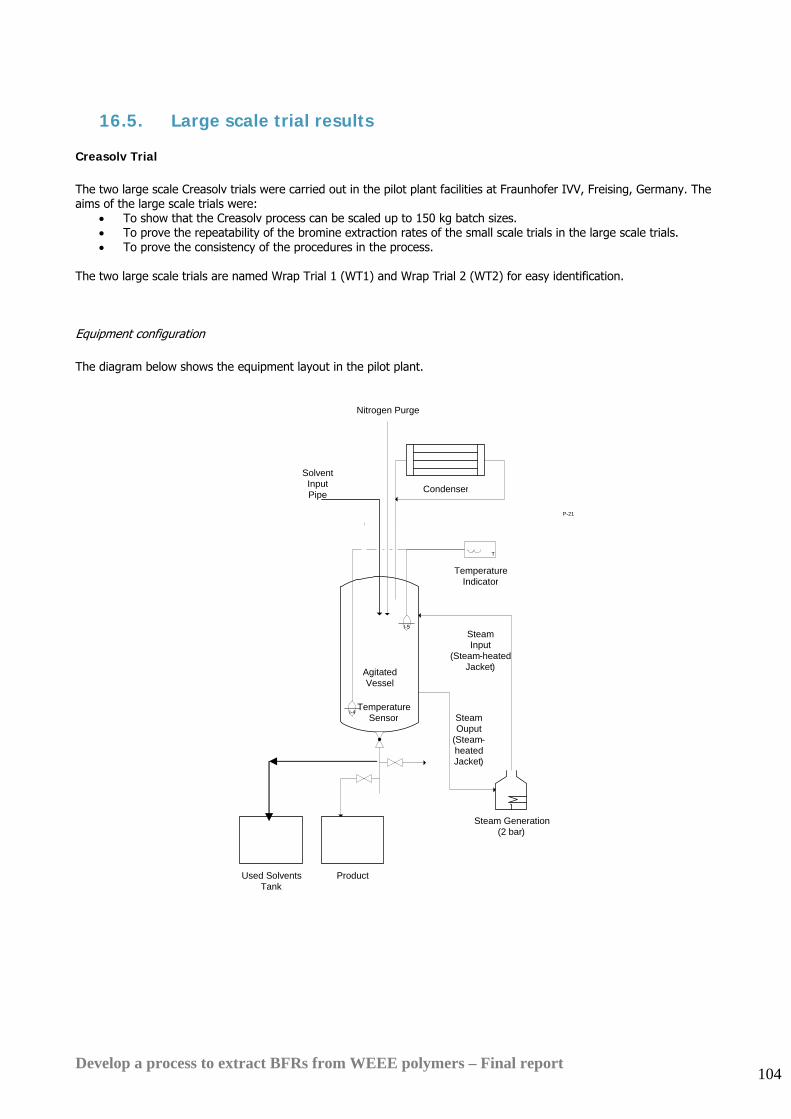
Develop a process to extract BFRs from WEEE polymers – Final report 104
16.5. Large scale trial results Creasolv Trial The two large scale Creasolv trials were carried out in the pilot plant facilities at Fraunhofer IVV, Freising, Germany. The aims of the large scale trials were:
• To show that the Creasolv process can be scaled up to 150 kg batch sizes. • To prove the repeatability of the bromine extraction rates of the small scale trials in the large scale trials. • To prove the consistency of the procedures in the process.
The two large scale trials are named Wrap Trial 1 (WT1) and Wrap Trial 2 (WT2) for easy identification. Equipment configuration The diagram below shows the equipment layout in the pilot plant.
T
Temperature Indicator
P-4
Condenser
P-21
ProductUsed Solvents Tank
Steam Generation(2 bar)
Nitrogen Purge
AgitatedVessel
SolventInput Pipe
I-4
I-5Steam Input
(Steam-heatedJacket)
Steam Ouput
(Steam-heatedJacket)
Temperature Sensor
Develop a process to extract BFRs from WEEE polymers – Final report 105
Feed material The input black waste polymers were derived from a TV-set dismantling line in Germany. They were shredded to particles of 20mm and subjected to a sink & float separation to enrich BFR containing polymers. The picture below shows the input shredded polymer chips.
Trial summary The dissolution and filtration of the polymer solution was carried out in 3 batches prior to the trial in the pilot plant. The picture below shows the technical scale plant, where the dissolution and filtration was carried out.

Develop a process to extract BFRs from WEEE polymers – Final report 106
The photograph below shows the reactor at Fraunhofer IVV where the large scale trials were conducted:
The details of the intermediate precipitation and solvent regeneration steps are confidential. The product from the final step of WT1 prior to final solvent removal is shown below. The size distribution of the particles varies significantly.
Develop a process to extract BFRs from WEEE polymers – Final report 107
The particle size distribution was improved significantly in the final large scale trial by Fraunhofer IVV (WT3) as a result of a further confidential process change. Results The table below shows the amount of bromine that was left in the polymer compared to the initial amount of bromine in the polymer and the percentage removal of bromine. All results are corrected for solvent content to convert to dry polymer basis. The dry mass values have been calculated from the X-Ray Fluorescence Spectroscopy analytical results provided by Fraunhofer IVV for the bromine and antimony concentrations that have been removed and the solvent content measured for the polymer at each process step.
Bromine content WT1
Antimony content WT1
Bromine content WT2
Antimony content WT2
WEEE Input 8.81% 4.44% 6.99% 2.83% Product 0.04% 2.20% 0.12% 2.29%
% Reduction 99.5% 50.5% 98.3% 19.08% In both trials, there is a more than 98% removal of bromine from the polymer and although only the product from WT1 meets the specification of less than 0.1%, the product from WT2 is only off-specification by about 0.02%. There was a reduction in antimony content in both trials, with a greater reduction of 50% in WT1, as compared to only 20% in WT2. This is likely to be because there was a higher starting concentration of antimony in WT1 as compared to WT2. Types of BFR Removed The product from trial WT1 was analysed in more detail to investigate the effectiveness of the Creasolv process in removing the various types of BFRs, namely Octa BDE, DecaBDE, TBBPA and TBPE. Samples from the products were tested by Fraunhofer IVV using gas chromatography. The table below shows the concentrations of the various types of BFRs measured in the feed polymer and the product from trial WT1: Flame retardant type OctaBDE DecaBDe TBBPA TBPE Average concentration in polymer feed 3.36% 0.77% 2.43% 0.49%Average concentration in Creasolv product 0.0092% 0.0089% 0.0037% 0.0008%% Removal 99.7% 98.8% 99.8% 99.8%
The table below shows the concentrations of the various types of BFRs measured in the filtered polymer solution and product from trial WT2: Flame retardant type OctaBDE DecaBDe TBBPA TBPE Average concentration in polymer feed 3.27% 1.36% 6.09% 0.47%Average concentration in Creasolv product 0.0199% 0.0182% 0.143% 0.0018%% Removal 99.4% 98.7% 97.6% 99.6%
All the values above have been corrected for estimated dry polymer content.

Develop a process to extract BFRs from WEEE polymers – Final report 108
Conclusions for the Creasolv trial The large scale trials WT1 and WT2 have proven that the process can indeed be scaled up to a much larger scale. The analytical results have supported this by showing that the bromine contents in the final products are close to or within the target of 0.1%, and thus demonstrate very good and repeatable extraction rates at close to production scale. Following the WRAP-funded trials Fraunhofer IVV conducted a further large scale trial on their own. Further optimization of the process in terms of agitation, etc will allow for improved bromine extraction rates and enable the target bromine concentration to be met reliably. After the second large scale trial WT2, Fraunhofer IVV proceeded to conduct a third large scale Creasolv trial. This trial achieved similar results to trials WT1 and WT2. Further improvements to simplify the process sequence were made which resulted in slightly lower capital and operating costs.
Develop a process to extract BFRs from WEEE polymers – Final report 109
Solvent recovery trials The solvent recovery unit uses a simple batch evaporation process to recover the remaining solvent from the filter and solvent regeneration unit residues. In this case, the solvents to be recovered are the Creasolv solvents and the contaminants are the extracted BFRs, antimony trioxide, inerts from the initial filtration and any undissolved polymers. The solvent is vapourised by hot oil in the heating jacket surrounding the vessel. The vapours are then conveyed to a condenser to be cooled by cooling water. The condensed solvent is collected in a tank for its reuse. The solvent recovery vessel is equipped with a rotating blade which keeps the contents to be treated constantly in movement allowing maximum extraction of the solvent, concentration of the residues and avoids the residues sticking to the boiler's walls and bottom. The picture below on the left shows the solvent recovery unit, while the picture on the right shows the interior of the solvent recovery vessel.
Source: Solutex- Solvent Recycling Units, Industrial Series Brochure Two laboratory solvent recovery trials were carried out on 8 March 2006:
1. to establish that the solvent recovery unit was able to recover the solvent from the filter residue and produce a dry residue, suitable for landfill.
2. to establish that the solvent recovery unit was able to recover the solvent from the solvent regeneration slurry and produce a dry residue, suitable for landfill.
The main difference in the two trials was the feed material. The drying agent used in both trials remained the same- Tix-dry (a high surface area silica powder used in the food and pharmaceutical industries). This material had been proven to work successfully in previous trials. Tix-dry is however rather expensive at around £2-3 per kg.
Develop a process to extract BFRs from WEEE polymers – Final report 110
Feed materials The first trial used the filter residue from the 1st large scale Creasolv trial (WT1). This contained styrenic WEEE polymers dissolved in Creasolv Solvents, together with any undissolved polymers (such as ABS), insoluble additives and inerts such as paper, fluff and metals. The filter residue infeed had a solvent concentration of 44%. The picture below shows the filter residue feed before the solvent recovery process:
The second trial used the solvent regeneration slurry also from the 1st large scale Creasolv trial (WT1). This contained WEEE polymer dissolved in Creasolv Solvents and a high concentration of BFRs. The solvent regeneration slurry had an infeed solvent concentration of 53%. The picture below shows the solvent regeneration residue before the solvent recovery process.
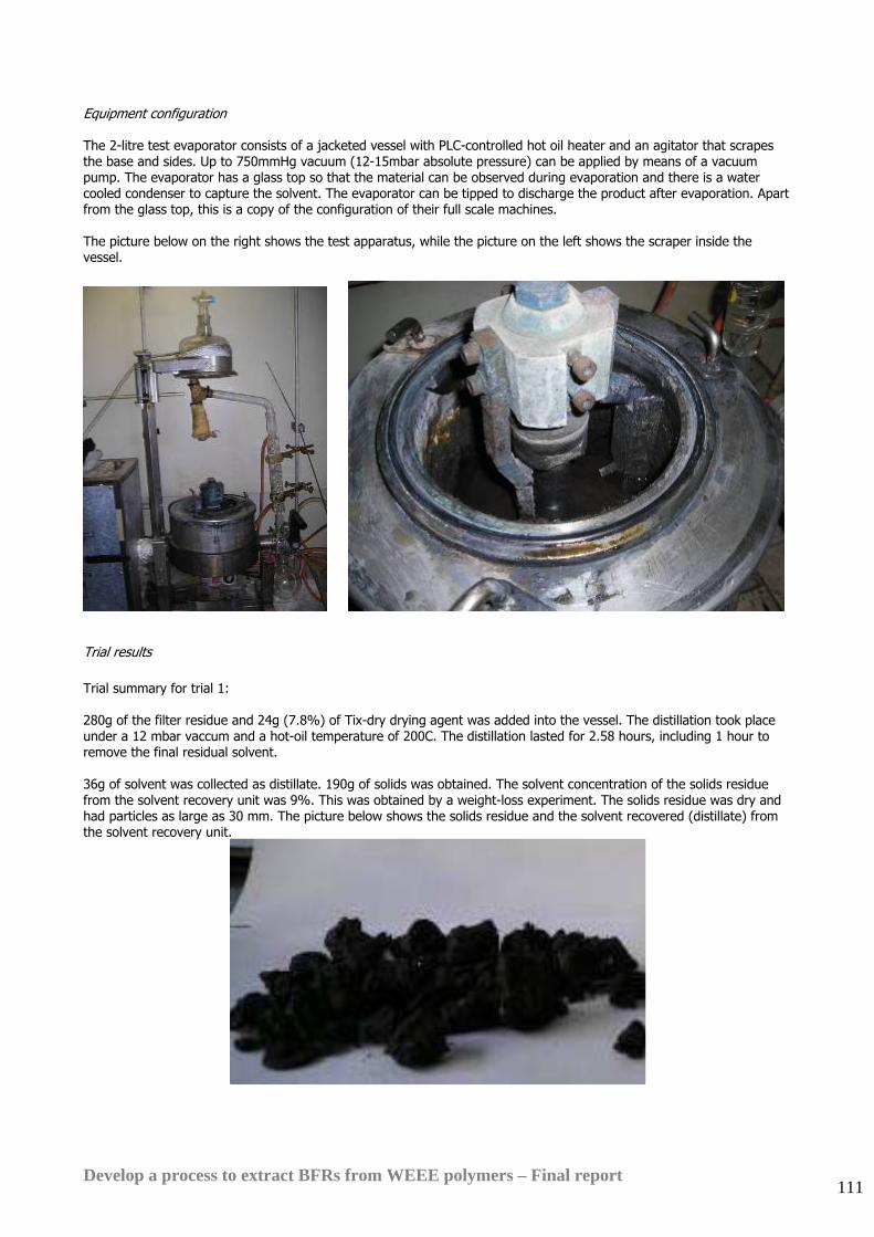
Develop a process to extract BFRs from WEEE polymers – Final report 111
Equipment configuration The 2-litre test evaporator consists of a jacketed vessel with PLC-controlled hot oil heater and an agitator that scrapes the base and sides. Up to 750mmHg vacuum (12-15mbar absolute pressure) can be applied by means of a vacuum pump. The evaporator has a glass top so that the material can be observed during evaporation and there is a water cooled condenser to capture the solvent. The evaporator can be tipped to discharge the product after evaporation. Apart from the glass top, this is a copy of the configuration of their full scale machines. The picture below on the right shows the test apparatus, while the picture on the left shows the scraper inside the vessel.
Trial results Trial summary for trial 1: 280g of the filter residue and 24g (7.8%) of Tix-dry drying agent was added into the vessel. The distillation took place under a 12 mbar vaccum and a hot-oil temperature of 200C. The distillation lasted for 2.58 hours, including 1 hour to remove the final residual solvent. 36g of solvent was collected as distillate. 190g of solids was obtained. The solvent concentration of the solids residue from the solvent recovery unit was 9%. This was obtained by a weight-loss experiment. The solids residue was dry and had particles as large as 30 mm. The picture below shows the solids residue and the solvent recovered (distillate) from the solvent recovery unit.
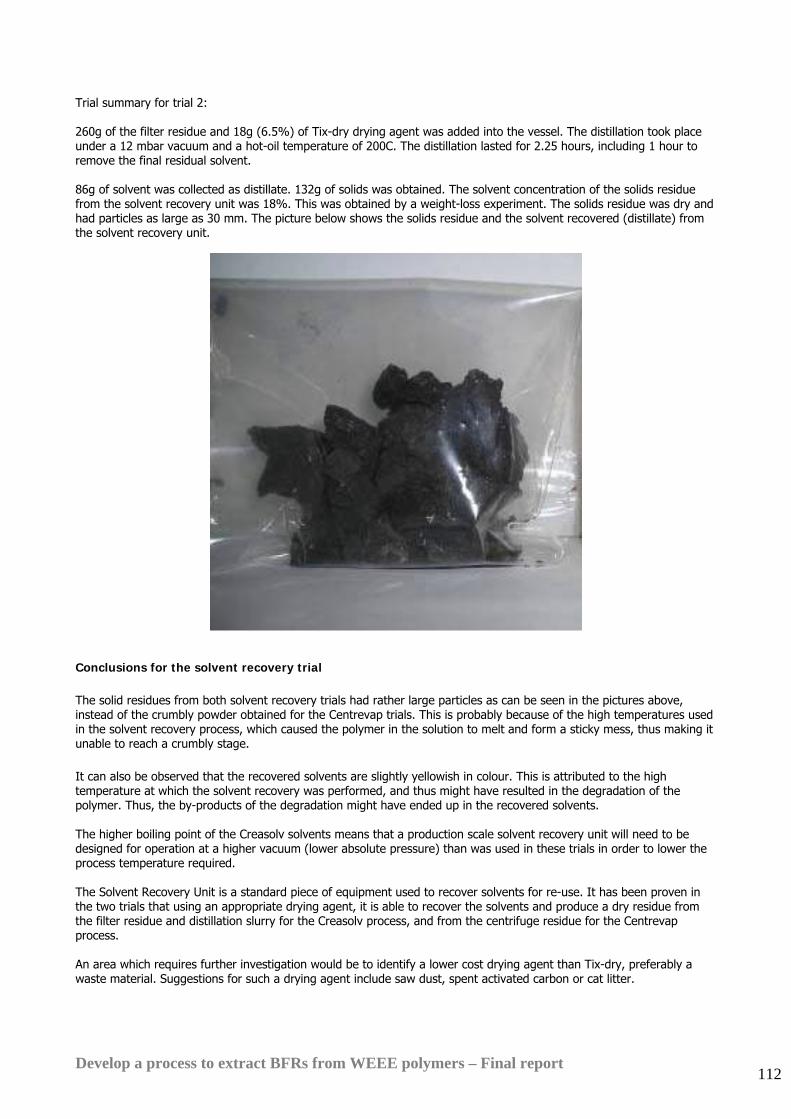
Develop a process to extract BFRs from WEEE polymers – Final report 112
Trial summary for trial 2: 260g of the filter residue and 18g (6.5%) of Tix-dry drying agent was added into the vessel. The distillation took place under a 12 mbar vacuum and a hot-oil temperature of 200C. The distillation lasted for 2.25 hours, including 1 hour to remove the final residual solvent. 86g of solvent was collected as distillate. 132g of solids was obtained. The solvent concentration of the solids residue from the solvent recovery unit was 18%. This was obtained by a weight-loss experiment. The solids residue was dry and had particles as large as 30 mm. The picture below shows the solids residue and the solvent recovered (distillate) from the solvent recovery unit.
Conclusions for the solvent recovery trial The solid residues from both solvent recovery trials had rather large particles as can be seen in the pictures above, instead of the crumbly powder obtained for the Centrevap trials. This is probably because of the high temperatures used in the solvent recovery process, which caused the polymer in the solution to melt and form a sticky mess, thus making it unable to reach a crumbly stage. It can also be observed that the recovered solvents are slightly yellowish in colour. This is attributed to the high temperature at which the solvent recovery was performed, and thus might have resulted in the degradation of the polymer. Thus, the by-products of the degradation might have ended up in the recovered solvents. The higher boiling point of the Creasolv solvents means that a production scale solvent recovery unit will need to be designed for operation at a higher vacuum (lower absolute pressure) than was used in these trials in order to lower the process temperature required. The Solvent Recovery Unit is a standard piece of equipment used to recover solvents for re-use. It has been proven in the two trials that using an appropriate drying agent, it is able to recover the solvents and produce a dry residue from the filter residue and distillation slurry for the Creasolv process, and from the centrifuge residue for the Centrevap process. An area which requires further investigation would be to identify a lower cost drying agent than Tix-dry, preferably a waste material. Suggestions for such a drying agent include saw dust, spent activated carbon or cat litter.
Develop a process to extract BFRs from WEEE polymers – Final report 113
With the appropriate operating conditions and suitably effective drying agent, a final dry crumbly residue will be obtained, and the final solvent content in the residue can be significantly reduced. Separation of bromine and antimony in the residues for feedstock recycling Both BFRs and antimony trioxide are found in the residues from the solvent recovery system. Fraunhofer IVV has developed a low cost recovery technique which leaves a bromine-rich fraction containing only 20ppm of antimony trioxide (plus drying powder and a small amount of residual polymer) and a second antimony-rich fraction with much reduced bromine content and which contains further drying powder, some residual polymer and the other impurities that were present in the input polymer. Mixed bromine and antimony residues cannot be recovered so these separated residue fractions will be attractive to the bromine and antimony industries for material recovery and should avoid the need for landfill of the process residues. However, for prudence, the financial projections presented in this report and also the environmental impact assessments assume that the bromine and antimony residues must be landfilled.
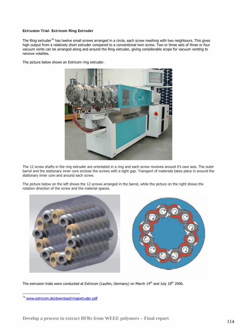
Develop a process to extract BFRs from WEEE polymers – Final report 114
Extrusion Trial- Extricom Ring Extruder The Ring extruder74 has twelve small screws arranged in a circle, each screw meshing with two neighbours. This gives high output from a relatively short extruder compared to a conventional twin screw. Two or three sets of three or four vacuum vents can be arranged along and around the Ring extruder, giving considerable scope for vacuum venting to remove volatiles. The picture below shows an Extricom ring extruder.
The 12 screw shafts in the ring extruder are orientated in a ring and each screw revolves around it’s own axis. The outer barrel and the stationary inner core enclose the screws with a tight gap. Transport of materials takes place in around the stationary inner core and around each screw. The picture below on the left shows the 12 screws arranged in the barrel, while the picture on the right shows the rotation direction of the screw and the material spaces.
The extrusion trials were conducted at Extricom (Laufen, Germany) on March 14th and July 18th 2006.
74 www.extricom.de/download/ringextruder.pdf
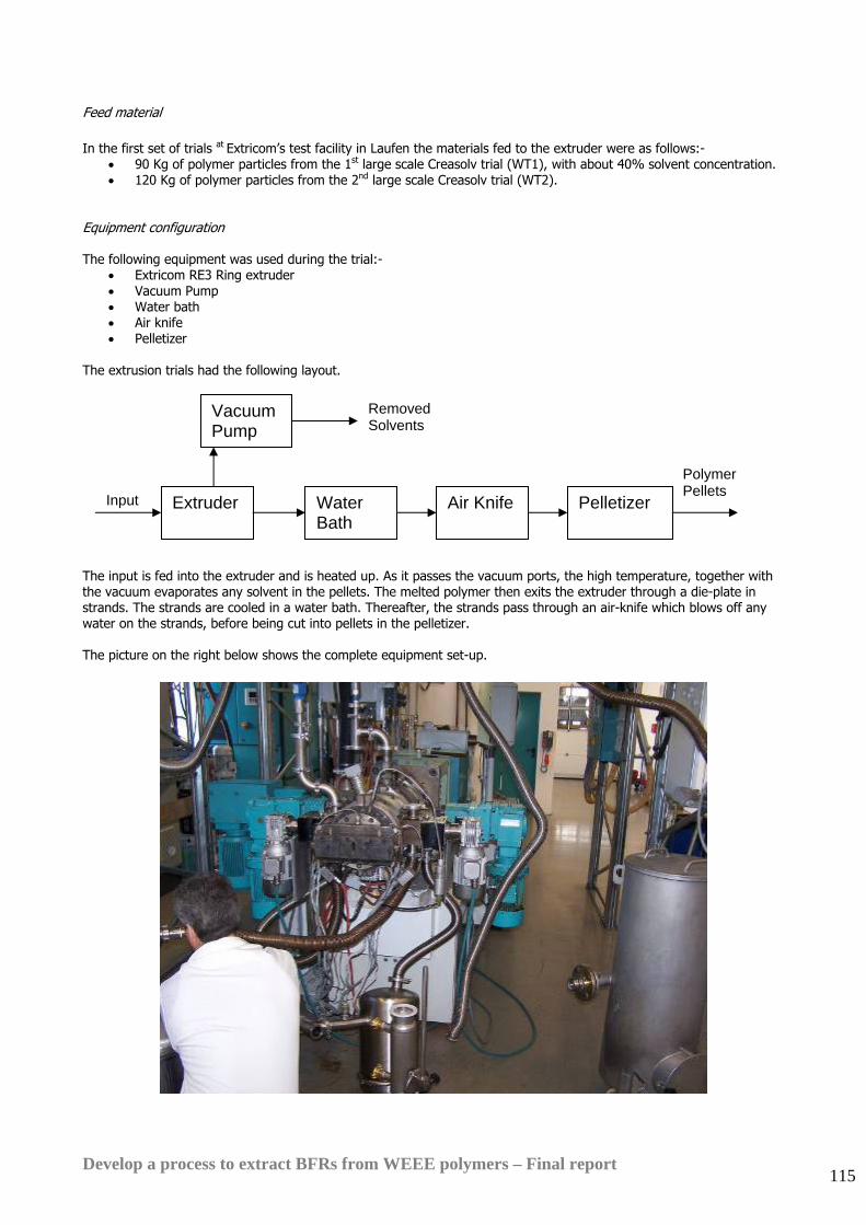
Develop a process to extract BFRs from WEEE polymers – Final report 115
Feed material In the first set of trials at Extricom’s test facility in Laufen the materials fed to the extruder were as follows:-
• 90 Kg of polymer particles from the 1st large scale Creasolv trial (WT1), with about 40% solvent concentration. • 120 Kg of polymer particles from the 2nd large scale Creasolv trial (WT2).
Equipment configuration The following equipment was used during the trial:-
• Extricom RE3 Ring extruder • Vacuum Pump • Water bath • Air knife • Pelletizer
The extrusion trials had the following layout. The input is fed into the extruder and is heated up. As it passes the vacuum ports, the high temperature, together with the vacuum evaporates any solvent in the pellets. The melted polymer then exits the extruder through a die-plate in strands. The strands are cooled in a water bath. Thereafter, the strands pass through an air-knife which blows off any water on the strands, before being cut into pellets in the pelletizer. The picture on the right below shows the complete equipment set-up.
Extruder
Vacuum Pump
Water Bath
Air Knife Pelletizer Input
Removed Solvents
Polymer Pellets
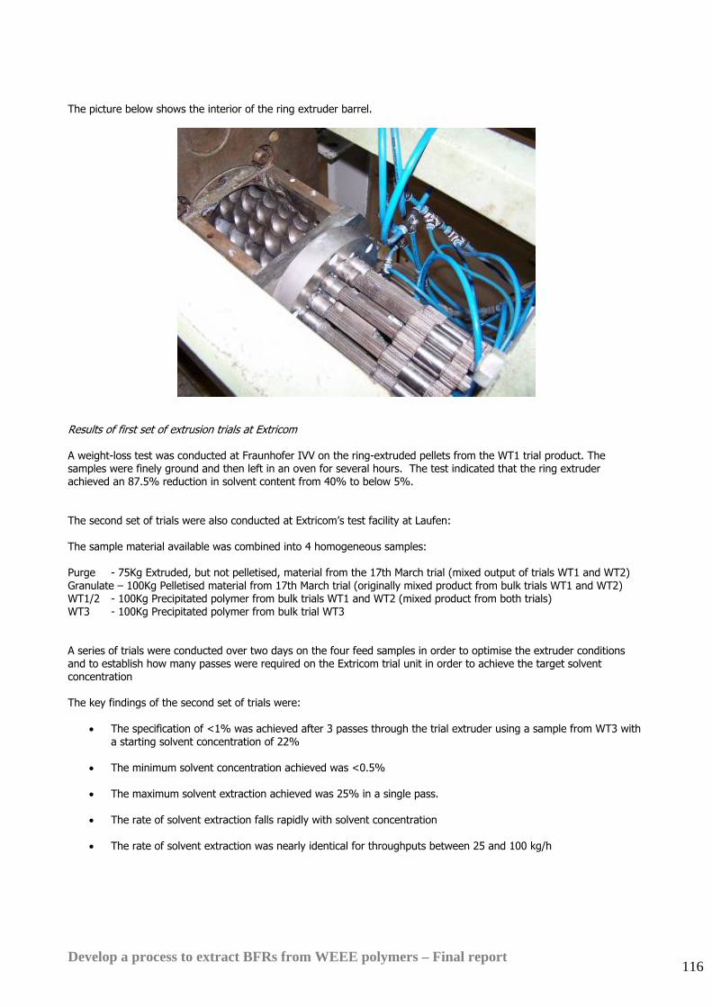
Develop a process to extract BFRs from WEEE polymers – Final report 116
The picture below shows the interior of the ring extruder barrel.
Results of first set of extrusion trials at Extricom A weight-loss test was conducted at Fraunhofer IVV on the ring-extruded pellets from the WT1 trial product. The samples were finely ground and then left in an oven for several hours. The test indicated that the ring extruder achieved an 87.5% reduction in solvent content from 40% to below 5%. The second set of trials were also conducted at Extricom’s test facility at Laufen: The sample material available was combined into 4 homogeneous samples: Purge - 75Kg Extruded, but not pelletised, material from the 17th March trial (mixed output of trials WT1 and WT2) Granulate – 100Kg Pelletised material from 17th March trial (originally mixed product from bulk trials WT1 and WT2) WT1/2 - 100Kg Precipitated polymer from bulk trials WT1 and WT2 (mixed product from both trials) WT3 - 100Kg Precipitated polymer from bulk trial WT3 A series of trials were conducted over two days on the four feed samples in order to optimise the extruder conditions and to establish how many passes were required on the Extricom trial unit in order to achieve the target solvent concentration The key findings of the second set of trials were:
• The specification of <1% was achieved after 3 passes through the trial extruder using a sample from WT3 with a starting solvent concentration of 22%
• The minimum solvent concentration achieved was <0.5%
• The maximum solvent extraction achieved was 25% in a single pass.
• The rate of solvent extraction falls rapidly with solvent concentration
• The rate of solvent extraction was nearly identical for throughputs between 25 and 100 kg/h

Develop a process to extract BFRs from WEEE polymers – Final report 117
Conclusions for the extrusion trials These trials have demonstrated that the ring extruder with multiple vacuum vents is capable of extraction of a large amount of the solvent from Creasolv materials and can reduce solvent content to below 1% Further modifications to the extruder and vacuum system configuration should improve solvent recovery further and allow reduction to well below 1% solvent content in a single pass. Analysis of the results of the ring extruder trials indicated that it should also be possible to achieve the same solvent reduction in a large twin screw unit. One other option which was not tested in this project is the possibility of using a devolatiliser combined with an extruder to remove the residual solvent. This technique is commonly used for removal of water from recycled PET. The best known equipment for this application is the ‘Vacurema’ unit from Erema in Austria75. Erema was consulted during the project to see if they would be able to assist with trials but they declined because their test facility was not available or rated for explosion-proof operations. However Erema have recently expressed interest in developing solvent-based recycling applications for their equipment. It would be interesting to test the Vacurema unit for final solvent removal in future. It has undergone a lot of development for water removal so this experience is likely to be beneficial for solvent extraction.
75 www.erema.at

Develop a process to extract BFRs from WEEE polymers – Final report 118
16.6. Mass balance A full scale mass balance has been prepared for the Creasolv process at a throughput of 10,000te/yr WEEE polymer. This mass balance is based on the experimental results measured in the technical and large scale trials. The detailed results are confidential but the mass balance may be summarised as follows: INPUT (te/yr) OUTPUT (te/yr)
Stream No. WEEE polymer
Input Make-Up Solvents Drying Agent
Polymer product
Residue to Landfill
Polymer 7,920 7,656 264 BFR 1,000 4 996 Antimony 80 3 77 Inerts 1,000 0 1,000 Solvents 143 38 105 Drying Agent 0 486 0 486 Total 10,000 143 486 7,701 2,928 Total Input: 10,629 te/yr Total Output: 10,629 te/yr Part of the solvent that is consumed will be lost in the residue that is disposed to landfill and part will be present at less than 1% in the final polymer product. At this level it is not expected that the solvent will have any detrimental effect on product quality or moulding performance for the injection moulding and extrusion applications targeted by this process. The residual solvent in the product is non-toxic and relatively involatile. Note that as stated in Section 14 above, the 10,000te/yr feed to the process represents the separated BFR-containing polymers from around 100,000te/yr of WEEE plastic or 400,000te/yr of collected WEEE items because about 25% of WEEE is polymer and about 10% of WEEE polymers contain BFRs.
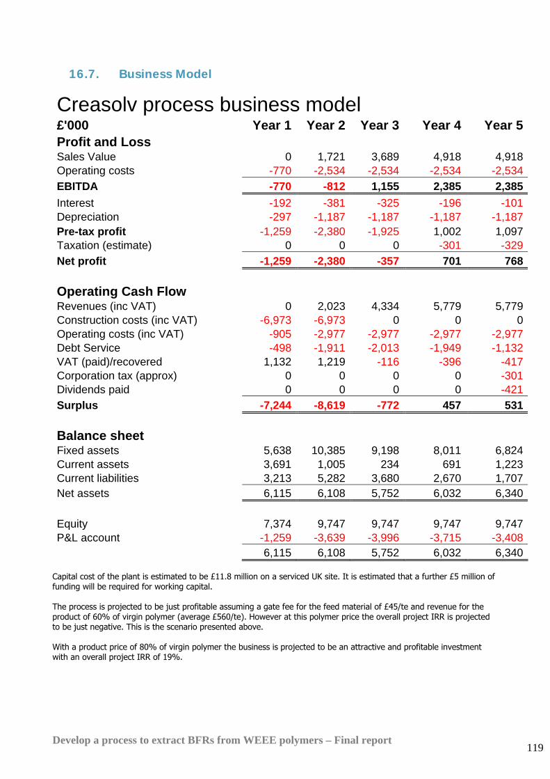
Develop a process to extract BFRs from WEEE polymers – Final report 119
16.7. Business Model
Creasolv process business model
£'000 Year 1 Year 2 Year 3 Year 4 Year 5Profit and Loss Sales Value 0 1,721 3,689 4,918 4,918Operating costs -770 -2,534 -2,534 -2,534 -2,534EBITDA -770 -812 1,155 2,385 2,385Interest -192 -381 -325 -196 -101Depreciation -297 -1,187 -1,187 -1,187 -1,187Pre-tax profit -1,259 -2,380 -1,925 1,002 1,097Taxation (estimate) 0 0 0 -301 -329Net profit -1,259 -2,380 -357 701 768
Operating Cash Flow Revenues (inc VAT) 0 2,023 4,334 5,779 5,779Construction costs (inc VAT) -6,973 -6,973 0 0 0Operating costs (inc VAT) -905 -2,977 -2,977 -2,977 -2,977Debt Service -498 -1,911 -2,013 -1,949 -1,132VAT (paid)/recovered 1,132 1,219 -116 -396 -417Corporation tax (approx) 0 0 0 0 -301Dividends paid 0 0 0 0 -421Surplus -7,244 -8,619 -772 457 531
Balance sheet Fixed assets 5,638 10,385 9,198 8,011 6,824Current assets 3,691 1,005 234 691 1,223Current liabilities 3,213 5,282 3,680 2,670 1,707Net assets 6,115 6,108 5,752 6,032 6,340 Equity 7,374 9,747 9,747 9,747 9,747P&L account -1,259 -3,639 -3,996 -3,715 -3,408 6,115 6,108 5,752 6,032 6,340
Capital cost of the plant is estimated to be £11.8 million on a serviced UK site. It is estimated that a further £5 million of funding will be required for working capital. The process is projected to be just profitable assuming a gate fee for the feed material of £45/te and revenue for the product of 60% of virgin polymer (average £560/te). However at this polymer price the overall project IRR is projected to be just negative. This is the scenario presented above. With a product price of 80% of virgin polymer the business is projected to be an attractive and profitable investment with an overall project IRR of 19%.
Develop a process to extract BFRs from WEEE polymers – Final report 120
16.8. Discussion The Creasolv process uses an elegant combination of proprietary solvents which removes brominated flame retardants effectively from HIPS and ABS. As a result of design and scale-up work with Axion and other members of the WRAP project team it has been modified so that it achieves an excellent reduction in BFR content. Technical and large scale trials reliably achieved or nearly achieved the target final BFR concentration set for this project (less than 0.1% total). The process removed all BFR types found in the chosen WEEE polymer samples including TBBPA and OctaBDE. A solvent regeneration and recovery system has been designed and tested which should cut solvent losses from the process to commercially and environmentally acceptable levels. The assumption in the financial projections presented in this report is that the final recycled product will sell at around 60% of virgin polymer price (average £560/te). This is higher than the average price used in the models presented in the second interim report for this project (47% of virgin). It was decided to increase the assumed selling price because market intelligence gathered in the course of the project by Axion has demonstrated that there is growing unmet demand from manufacturers of electrical equipment for high grade recycled polymers. Demand is growing because manufacturers want to diversify their sources of polymer supply, reduce costs and also include recycled content for marketing reasons. Several manufacturers have indicated informally that they would be prepared to pay up to 80% of virgin price (£750/te) for high grade recyclate. The business model indicates that, using Axion’s assumptions, the process should be commercially viable in the UK at 10,000te/year throughput with a gate fee for the segregated and size-reduced input material of £45/te. At present in the UK this type of BFR-containing material is being exported to the Far East for mechanical recycling and is attracting positive prices up to £100/te, depending on quality. If the regulatory environment changes and either the Chinese or European authorities refuse to allow direct re-use of BFR-containing polymers then the Creasolv process would become competitive as the alternative disposal routes would be incineration with energy recovery or landfill. Both of these disposal routes would attract minimum gate fees of at least £45/te in the UK. If there is positive demand for halogen-free recyclate from equipment manufacturers and the price for high quality recycled polymer rises to around 80% of virgin polymer price then the Creasolv process would be an attractive investment although it would still need to attract a gate fee of £45/te for the input material. Tests by Fraunhofer IVV indicate that it will be possible to separate the residues from the process into a bromine containing fraction and an antimony containing fraction by means of a relatively inexpensive process change. This should make the residues attractive for recycling to feedstock by the bromine and antimony industries. This would reduce operating costs by eliminating landfill costs for the residues and also further improve the environmental impact of the Creasolv process option. Some technical concerns remain: The process uses relative simple and well-tried technology but the process sequence is quite complex with several variables to control. Before investment in a full scale plant further trials will be required to prove that the process can be controlled effectively and deliver consistent output material composition. The final solvent recovery step using a twin screw or ring extruder is novel and has been tested in three trials. In these trials solvent content of the polymer has been reduced to below 0.5%, but only with 3 passes through the trial extruder. Indications from the first three trial sessions are that it should be possible to optimise the extruder configuration so that 0.5% final solvent concentration can be achieved in a single pass but this is still to be proven in practice. Further process development will be required to demonstrate this.
Develop a process to extract BFRs from WEEE polymers – Final report 121
17. Centrevap process trials
17.1. Centrevap process background The Centrevap process design was developed in the course of this project as a result of discussions between Axion and other project participants and observation of the results of other process trials conducted for the project. Similar process ideas have been patented previously in the US and Germany but differ in detail to the concept proposed here767778
17.2. Basis for the process design
It was observed that there is a difference in solubility between WEEE polymers and the additives they contain and that this could be exploited to remove the insoluble additives.
Several different solvents can be used to dissolve the styrenic polymers found in WEEE. A summary of the solubilities of the polymers and BFRs most often found in WEEE is presented in the second interim report for this project.
Unfortunately Penta BDE is completely soluble in all of these solvents and the other BFRs likely to be found in styrenic WEEE polymers are partly soluble.
Trials in the course of Phase 3 of this project have also demonstrated that the BFRs commonly found in WEEE polymers are partial soluble in the solvent used for this trial at the temperatures and concentrations that are required for practical process operation. This means that the Centrevap process is not a viable option for removal of BFRs from WEEE polymers down to the level targeted by this project
However the process should still have commercial potential as a method for separating any impurities and additives such as antimony trioxide, fillers and some pigments and stabilisers which are not soluble in the types of solvent which will dissolve styrenic polymers. These solvents include toluene, xylene, styrene, THF and dichloromethane for styrenic polymers and methyl ethyl ketone or tetra hydro furan for PVC.
All trials conducted for this project to date have used toluene as the solvent and HIPS as the target polymer.
76 US Patent 5,824,709, Oct 1998, ‘Method for recycling waste plastic material containing styrene polymer’, Motoshi Suka 77 German patent DE 4319180, August 1993, ‘Method for recycling products made of polystyrene’, BASF 78 German patent DE 4119303, June 1991. ‘Process to break down bulky composite plastic waste, particularly those containing chlorinated hydrocarbons’, Rolf Germerdonk
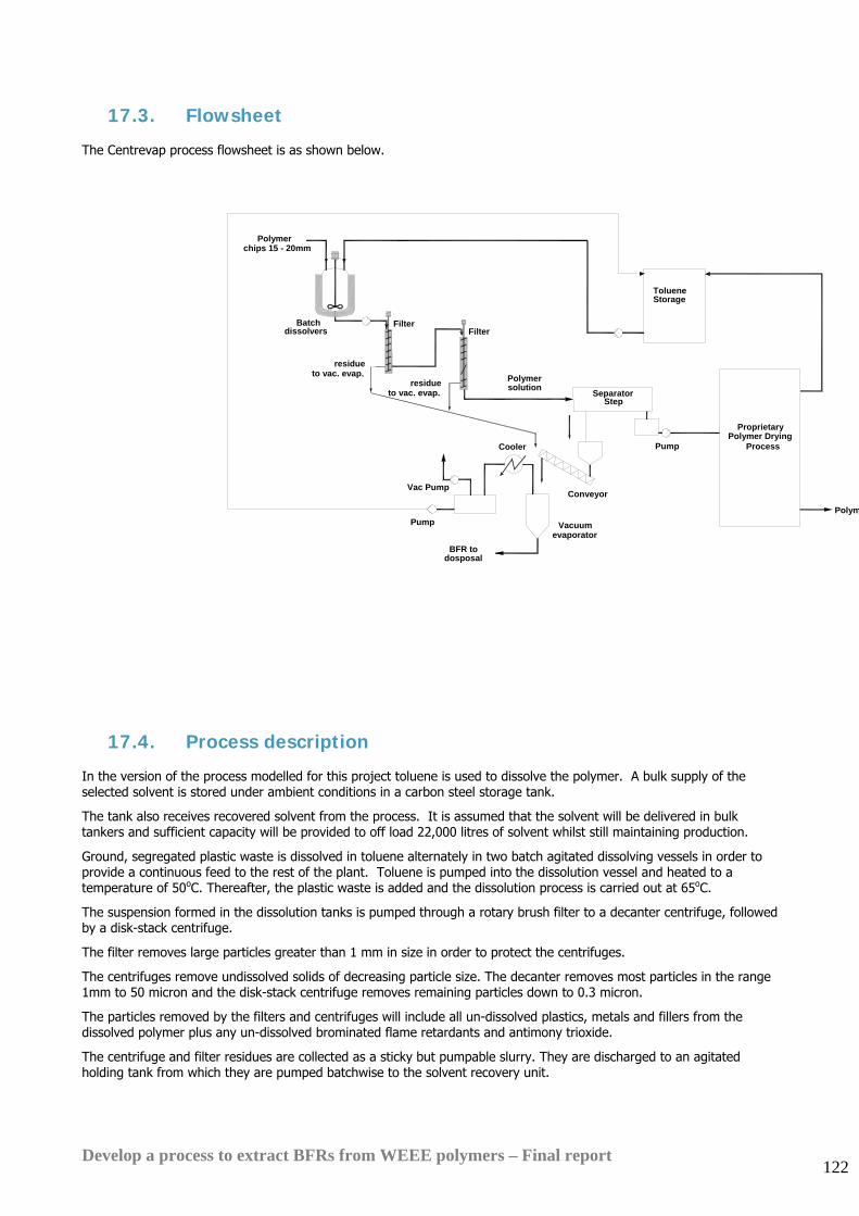
Develop a process to extract BFRs from WEEE polymers – Final report 122
17.3. Flowsheet The Centrevap process flowsheet is as shown below.
17.4. Process description In the version of the process modelled for this project toluene is used to dissolve the polymer. A bulk supply of the selected solvent is stored under ambient conditions in a carbon steel storage tank.
The tank also receives recovered solvent from the process. It is assumed that the solvent will be delivered in bulk tankers and sufficient capacity will be provided to off load 22,000 litres of solvent whilst still maintaining production.
Ground, segregated plastic waste is dissolved in toluene alternately in two batch agitated dissolving vessels in order to provide a continuous feed to the rest of the plant. Toluene is pumped into the dissolution vessel and heated to a temperature of 50oC. Thereafter, the plastic waste is added and the dissolution process is carried out at 65oC.
The suspension formed in the dissolution tanks is pumped through a rotary brush filter to a decanter centrifuge, followed by a disk-stack centrifuge.
The filter removes large particles greater than 1 mm in size in order to protect the centrifuges.
The centrifuges remove undissolved solids of decreasing particle size. The decanter removes most particles in the range 1mm to 50 micron and the disk-stack centrifuge removes remaining particles down to 0.3 micron.
The particles removed by the filters and centrifuges will include all un-dissolved plastics, metals and fillers from the dissolved polymer plus any un-dissolved brominated flame retardants and antimony trioxide.
The centrifuge and filter residues are collected as a sticky but pumpable slurry. They are discharged to an agitated holding tank from which they are pumped batchwise to the solvent recovery unit.
Conveyor
Pump
SeparatorPolymersolution
BFR todosposal
Pump
Cooler
Vac Pump
Vacuumevaporator
Polym
FilterBatch dissolvers Filter
residue
Polymer chips 15 - 20mm
residue
StorageToluene
to vac. evap.
to vac. evap.
ProprietaryPolymer Drying
Process
Step
Develop a process to extract BFRs from WEEE polymers – Final report 123
The solvent recovery unit is a steam-heated scraped surface heat transfer unit. It operates under vacuum and recovers the toluene from the slurry, leaving the BFR and fillers as a dry residue.
A high surface area powder such as spent activated carbon is added with the solvent recovery feed in order to ‘soak up’ residual polymer which would and a free-flowing solid residue is dropped into drums for off site disposal.
The liquid centrate leaving the disk stack centrifuge is discharged to a surge tank.
The centrate is then pumped to an evaporator system where the solvent is pumped to high pressure and heated then evaporated in a flash drum, followed by a wiped film evaporator where more solvent is removed.
In the wiped film evaporator the polymer is concentrated solvent and becomes a melt. The vaporised toluene is condensed and returned to the toluene storage tank for reuse.
The melt is discharged from the base of the evaporator and pumped by a high pressure gear pump direct as a melt into a vented extruder which recovers and recycles more solvent and produces a pelletised polymer product with less than 1% solvent content.
Total residence time through the whole process from after the primary filter to polymer pellet is of the order of 10-15 minutes. This minimises the potential for polymer degradation.
ENERGY USED • Hot utility requirement (Low Pressure Steam- 5 bar): 0.947 te of steam/te feed
• Cold utility requirement (Cold Water): 23 te/te feed
• Power (Average Draw): 579 kWh/te feed
EFFLUENTS PRODUCED
Water Effluent None
Vapour Effluent The evaporator will be fitted with a condenser, but some solvent will slip to atmosphere past the cold trap on the vacuum pump. A final clean up of this stream using activated carbon or a biological filter may be necessary to meet emission limits when detailed design is carried out.
BFR is discharged from the process in slurry in toluene. The toluene is recovered and recycled from the slurry yet there may be a very small amount of VOC emission when dropping the dried BFR and fillers into drums for disposal.
Solids Solid wastes comprising insoluble additives plus the high surface area powder used to assist the solvent recovery process are produced at the solvent recovery unit step. The residue will be discharged as a free-flowing dry solid and sent for disposal to landfill.
Develop a process to extract BFRs from WEEE polymers – Final report 124
17.5. Technical scale trials conducted Several technical scale trials and large scale trials have been carried out over the period of the project to fully explore the various process possibilities and test all the equipment involved in the plant design. Both pressure leaf precoat filtration and centrifugation were tested as possible methods for removing the very fine insoluble additives from the polymer solution. Precoat filtration potentially offered the advantage of being relatively low cost and well-tried technology. Numerous tests were conducted at technical scale in order to find a filter mesh/precoat combination which gave an acceptable filtration rate. No combination was found which gave a commercially viable filtration rate so this process route was abandoned in favour of centrifugation. Equipment tests were carried out on the centrifuge, thin-film evaporator (filmtruder), solvent recovery unit and extruder. The table below shows the trials that have been conducted over the course of the project which led to the final design of the process. Trial Aim of Trial Trials conducted Results Filtration To identify if filtration is a
suitable means of separating the insoluble BFR and antimony particles from the toluene-polymer solution.
Laboratory scale trials took place in August and September 2005. The trials were conducted at the laboratory of Ionic Solutions Ltd in Bradford. 43 different filter aid / support mesh combinations were tried with assistance from 5 different filter aid suppliers.
Filtration was rejected as a possible option. This is because the BFR and antimony particles were so fine that they required deposition of precoat filter media to aid the filtration. The filtration blocked repeatedly, and was difficult to control.
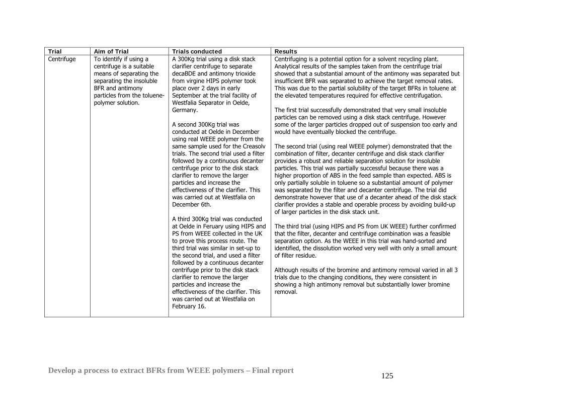
Develop a process to extract BFRs from WEEE polymers – Final report 125
Trial Aim of Trial Trials conducted Results Centrifuge To identify if using a
centrifuge is a suitable means of separating the separating the insoluble BFR and antimony particles from the toluene-polymer solution.
A 300Kg trial using a disk stack clarifier centrifuge to separate decaBDE and antimony trioxide from virgine HIPS polymer took place over 2 days in early September at the trial facility of Westfalia Separator in Oelde, Germany. A second 300Kg trial was conducted at Oelde in December using real WEEE polymer from the same sample used for the Creasolv trials. The second trial used a filter followed by a continuous decanter centrifuge prior to the disk stack clarifier to remove the larger particles and increase the effectiveness of the clarifier. This was carried out at Westfalia on December 6th. A third 300Kg trial was conducted at Oelde in Feruary using HIPS and PS from WEEE collected in the UK to prove this process route. The third trial was similar in set-up to the second trial, and used a filter followed by a continuous decanter centrifuge prior to the disk stack clarifier to remove the larger particles and increase the effectiveness of the clarifier. This was carried out at Westfalia on February 16.
Centrifuging is a potential option for a solvent recycling plant. Analytical results of the samples taken from the centrifuge trial showed that a substantial amount of the antimony was separated but insufficient BFR was separated to achieve the target removal rates. This was due to the partial solubility of the target BFRs in toluene at the elevated temperatures required for effective centrifugation. The first trial successfully demonstrated that very small insoluble particles can be removed using a disk stack centrifuge. However some of the larger particles dropped out of suspension too early and would have eventually blocked the centrifuge. The second trial (using real WEEE polymer) demonstrated that the combination of filter, decanter centrifuge and disk stack clarifier provides a robust and reliable separation solution for insoluble particles. This trial was partially successful because there was a higher proportion of ABS in the feed sample than expected. ABS is only partially soluble in toluene so a substantial amount of polymer was separated by the filter and decanter centrifuge. The trial did demonstrate however that use of a decanter ahead of the disk stack clarifier provides a stable and operable process by avoiding build-up of larger particles in the disk stack unit. The third trial (using HIPS and PS from UK WEEE) further confirmed that the filter, decanter and centrifuge combination was a feasible separation option. As the WEEE in this trial was hand-sorted and identified, the dissolution worked very well with only a small amount of filter residue. Although results of the bromine and antimony removal varied in all 3 trials due to the changing conditions, they were consistent in showing a high antimony removal but substantially lower bromine removal.
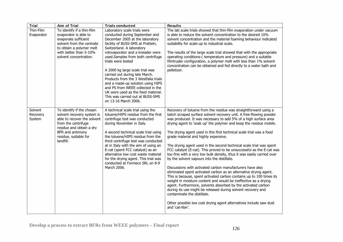
Develop a process to extract BFRs from WEEE polymers – Final report 126
Trial Aim of Trial Trials conducted Results Thin-Film Evaporator
To identify if a thin-film evaporator is able to evaporate sufficient solvent from the centrate to obtain a polymer melt with better than 5-10% solvent concentration.
Laboratory scale trials were conducted during September and December 2005 at the laboratory facility of BUSS-SMS at Pratteln, Switzerland. A laboratory rotovaporator and a kneader were used.Samples from both centrifuge trials were tested A 2000 kg large scale trial was carried out during late March. Products from the 3 Westfalia trials and a made-up solution using HIPS and PS from WEEE collected in the UK were used as the feed material. This was carried out at BUSS-SMS on 13-16 March 2006.
The lab scale trials showed that thin-film evaporation under vacuum is able to reduce the solvent concentration to the desired 10% solvent concentration and the material foaming behaviour indicated suitability for scale-up to industrial scale. The results of the large scale trial showed that with the appropriate operating conditions-( temperature and pressure) and a suitable filmtruder configuration, a polymer melt with less than 1% solvent concentration can be obtained and fed directly to a water bath and pelletizer.
Solvent Recovery System
To identify if the chosen solvent recovery system is able to recover the solvent from the centrifuge residue and obtain a dry BFR and antimony residue, suitable for landfill.
A technical scale trial using the toluene/HIPS residue from the first centrifuge test was conducted during November in Italy. A second technical scale trial using the toluene/HIPS residue from the third centrifuge test was conducted at in Italy with the aim of using an E-cat (spent FCC catalyst) as an alternative low cost waste material for the drying agent. This trial was conducted at Formeco SRL on 8-9 March 2006.
Recovery of toluene from the residue was straightforward using a batch scraped surface solvent recovery unit. A free-flowing powder was produced. It was necessary to add 5% of a high surface area drying agent to ‘soak up’ the polymer and keep the residue mobile. The drying agent used in this first technical scale trial was a food grade material and highly expensive. The drying agent used in the second technical scale trial was spent FCC catalyst (E-cat). This proved to be unsuccessful as the E-cat was too fine with a very low bulk density, thus it was easily carried over by the solvent vapours into the distillate. Discussions with activated carbon manufacturers have also eliminated spent activated carbon as an alternative drying agent. This is because, spent activated carbon contains up to 100 times its weight in moisture content and would be ineffective as a drying agent. Furthermore, solvents absorbed by the activated carbon during its use might be released during solvent recovery and contaminate the distillate. Other possible low cost drying agent alternatives include saw dust and ‘cat-liter’.
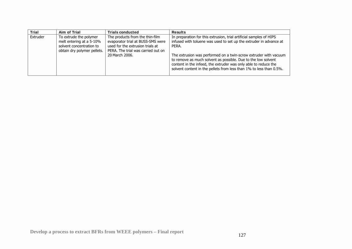
Develop a process to extract BFRs from WEEE polymers – Final report 127
Trial Aim of Trial Trials conducted Results Extruder To extrude the polymer
melt entering at a 5-10% solvent concentration to obtain dry polymer pellets.
The products from the thin-film evaporator trial at BUSS-SMS were used for the extrusion trials at PERA. The trial was carried out on 20 March 2006.
In preparation for this extrusion, trial artificial samples of HIPS infused with toluene was used to set up the extruder in advance at PERA. The extrusion was performed on a twin-screw extruder with vacuum to remove as much solvent as possible. Due to the low solvent content in the infeed, the extruder was only able to reduce the solvent content in the pellets from less than 1% to less than 0.5%.
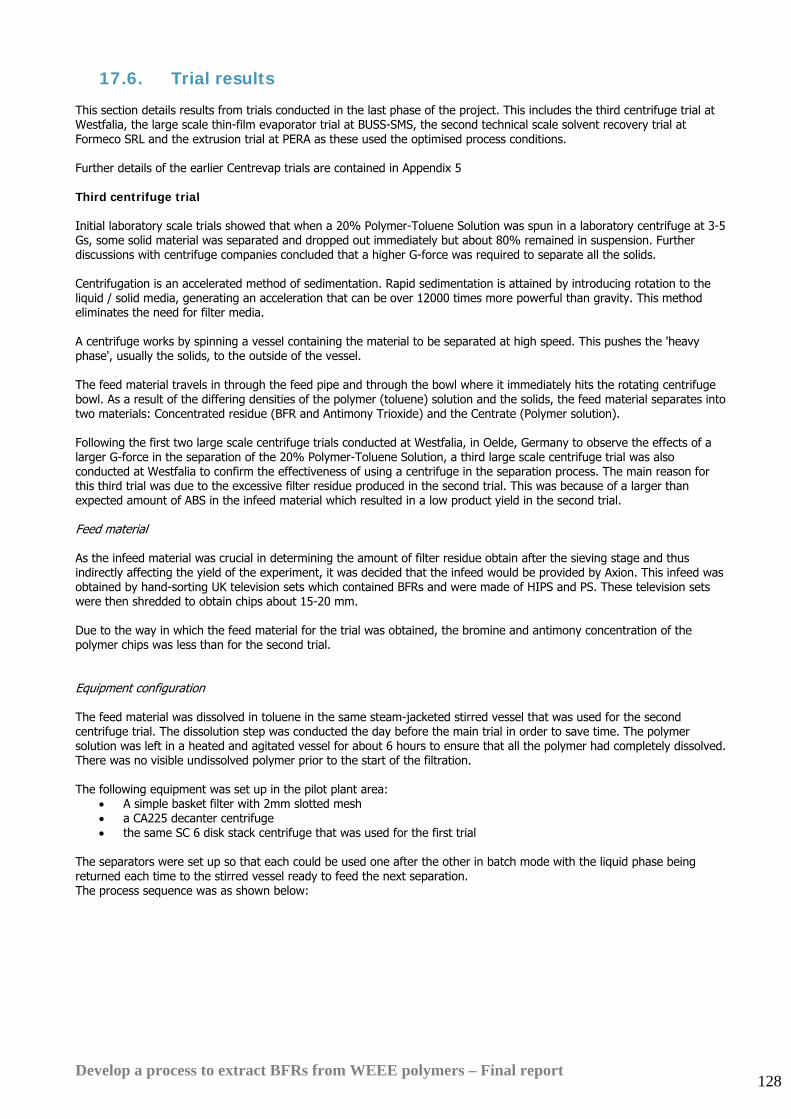
Develop a process to extract BFRs from WEEE polymers – Final report 128
17.6. Trial results This section details results from trials conducted in the last phase of the project. This includes the third centrifuge trial at Westfalia, the large scale thin-film evaporator trial at BUSS-SMS, the second technical scale solvent recovery trial at Formeco SRL and the extrusion trial at PERA as these used the optimised process conditions. Further details of the earlier Centrevap trials are contained in Appendix 5 Third centrifuge trial Initial laboratory scale trials showed that when a 20% Polymer-Toluene Solution was spun in a laboratory centrifuge at 3-5 Gs, some solid material was separated and dropped out immediately but about 80% remained in suspension. Further discussions with centrifuge companies concluded that a higher G-force was required to separate all the solids. Centrifugation is an accelerated method of sedimentation. Rapid sedimentation is attained by introducing rotation to the liquid / solid media, generating an acceleration that can be over 12000 times more powerful than gravity. This method eliminates the need for filter media. A centrifuge works by spinning a vessel containing the material to be separated at high speed. This pushes the 'heavy phase', usually the solids, to the outside of the vessel. The feed material travels in through the feed pipe and through the bowl where it immediately hits the rotating centrifuge bowl. As a result of the differing densities of the polymer (toluene) solution and the solids, the feed material separates into two materials: Concentrated residue (BFR and Antimony Trioxide) and the Centrate (Polymer solution). Following the first two large scale centrifuge trials conducted at Westfalia, in Oelde, Germany to observe the effects of a larger G-force in the separation of the 20% Polymer-Toluene Solution, a third large scale centrifuge trial was also conducted at Westfalia to confirm the effectiveness of using a centrifuge in the separation process. The main reason for this third trial was due to the excessive filter residue produced in the second trial. This was because of a larger than expected amount of ABS in the infeed material which resulted in a low product yield in the second trial. Feed material As the infeed material was crucial in determining the amount of filter residue obtain after the sieving stage and thus indirectly affecting the yield of the experiment, it was decided that the infeed would be provided by Axion. This infeed was obtained by hand-sorting UK television sets which contained BFRs and were made of HIPS and PS. These television sets were then shredded to obtain chips about 15-20 mm. Due to the way in which the feed material for the trial was obtained, the bromine and antimony concentration of the polymer chips was less than for the second trial. Equipment configuration The feed material was dissolved in toluene in the same steam-jacketed stirred vessel that was used for the second centrifuge trial. The dissolution step was conducted the day before the main trial in order to save time. The polymer solution was left in a heated and agitated vessel for about 6 hours to ensure that all the polymer had completely dissolved. There was no visible undissolved polymer prior to the start of the filtration. The following equipment was set up in the pilot plant area:
• A simple basket filter with 2mm slotted mesh • a CA225 decanter centrifuge • the same SC 6 disk stack centrifuge that was used for the first trial
The separators were set up so that each could be used one after the other in batch mode with the liquid phase being returned each time to the stirred vessel ready to feed the next separation. The process sequence was as shown below:
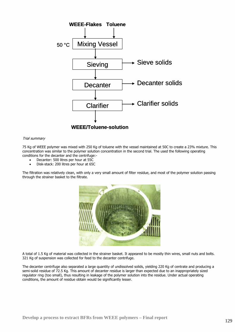
Develop a process to extract BFRs from WEEE polymers – Final report 129
Sieving
Decanter
Clarifier
Mixing Vessel
WEEE/Toluene-solution
Decanter solids
Clarifier solids
Sieve solids
50 °C
WEEE-Flakes Toluene
Sieving
Decanter
Clarifier
Mixing Vessel
WEEE/Toluene-solution
Decanter solids
Clarifier solids
Sieve solids
50 °C
WEEE-Flakes Toluene
Trial summary 75 Kg of WEEE polymer was mixed with 250 Kg of toluene with the vessel maintained at 50C to create a 23% mixture. This concentration was similar to the polymer solution concentration in the second trial. The used the following operating conditions for the decanter and the centrifuge:-
• Decanter: 500 litres per hour at 55C • Disk-stack: 200 litres per hour at 65C
The filtration was relatively clean, with only a very small amount of filter residue, and most of the polymer solution passing through the strainer basket to the filtrate.
A total of 1.5 Kg of material was collected in the strainer basket. It appeared to be mostly thin wires, small nuts and bolts. 321 Kg of suspension was collected for feed to the decanter centrifuge. The decanter centrifuge also separated a large quantity of undissolved solids, yielding 220 Kg of centrate and producing a semi-solid residue of 72.5 Kg. This amount of decanter residue is larger than expected due to an inappropriately sized regulator ring (too small), thus resulting in leakage of the polymer solution into the residue. Under actual operating conditions, the amount of residue obtain would be significantly lesser.
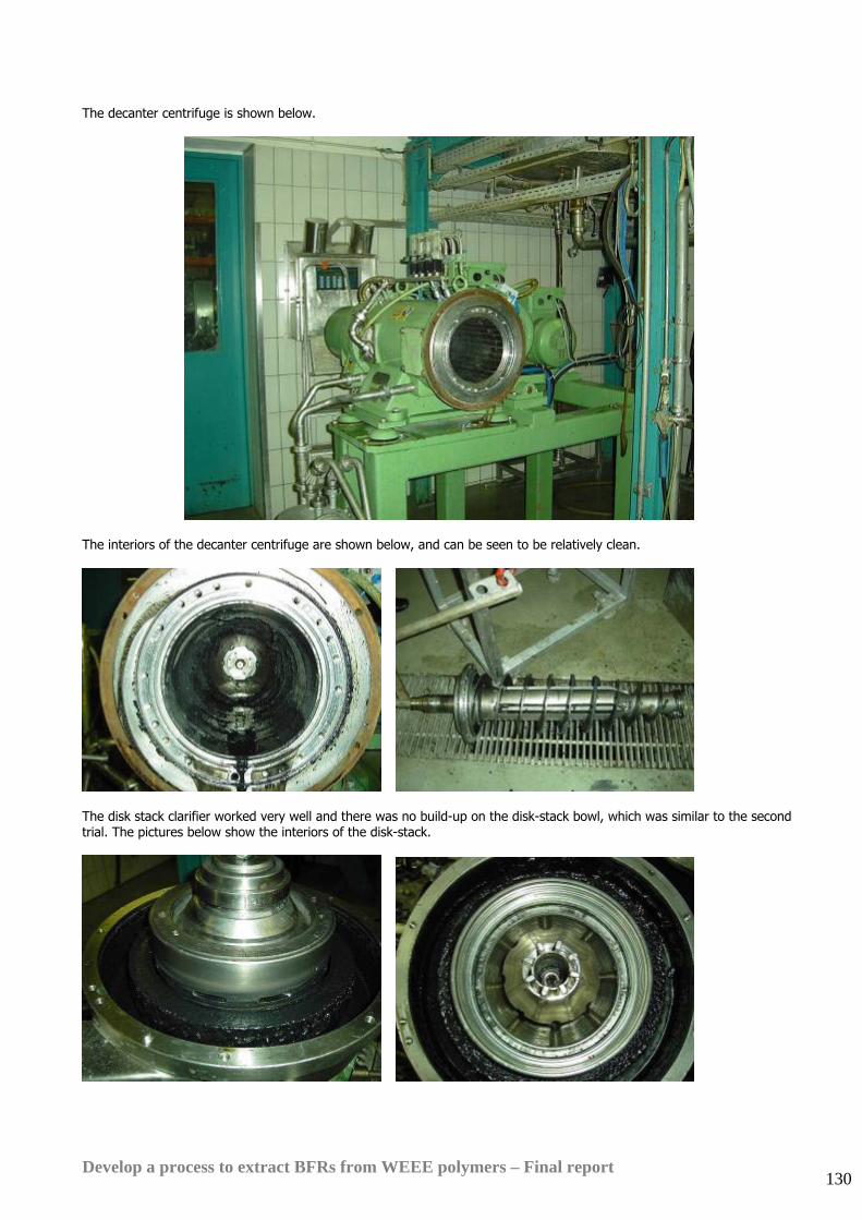
Develop a process to extract BFRs from WEEE polymers – Final report 130
The decanter centrifuge is shown below.
The interiors of the decanter centrifuge are shown below, and can be seen to be relatively clean.
The disk stack clarifier worked very well and there was no build-up on the disk-stack bowl, which was similar to the second trial. The pictures below show the interiors of the disk-stack.
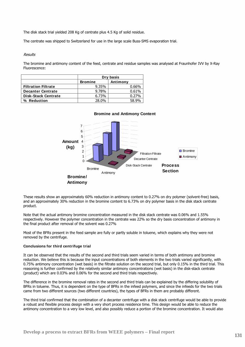
Develop a process to extract BFRs from WEEE polymers – Final report 131
The disk stack trial yielded 208 Kg of centrate plus 4.5 Kg of solid residue. The centrate was shipped to Switzerland for use in the large scale Buss-SMS evaporation trial. Results The bromine and antimony content of the feed, centrate and residue samples was analysed at Fraunhofer IVV by X-Ray Fluorescence: Dry basis Bromine Antimony Filtration Filtrate 9.35% 0.66% Decanter Centrate 9.78% 0.61% Disk-Stack Centrate 6.73% 0.27% % Reduction 28.0% 58.9%
Filtration Filtrate
Decanter Centrate
Disk-Stack CentrateBromine
Antimony
01234567
Amount (kg)
Process Section
Bromine/Antimony
Bromine and Antimony Content
Bromine
Antimony
These results show an approximately 60% reduction in antimony content to 0.27% on dry polymer (solvent-free) basis, and an approximately 30% reduction in the bromine content to 6.73% on dry polymer basis in the disk stack centrate product. Note that the actual antimony bromine concentration measured in the disk stack centrate was 0.06% and 1.55% respectively. However the polymer concentration in the centrate was 22% so the dry basis concentration of antimony in the final product after removal of the solvent was 0.27% Most of the BFRs present in the feed sample are fully or partly soluble in toluene, which explains why they were not removed by the centrifuge. Conclusions for third centrifuge trial It can be observed that the results of the second and third trials seem varied in terms of both antimony and bromine reduction. We believe this is because the input concentrations of both elements in the two trials varied significantly, with 0.75% antimony concentration (wet basis) in the filtrate solution on the second trial, but only 0.15% in the third trial. This reasoning is further confirmed by the relatively similar antimony concentrations (wet basis) in the disk-stack centrate (product) which are 0.03% and 0.06% for the second and third trials respectively. The difference in the bromine removal rates in the second and third trials can be explained by the differing solubility of BFRs in toluene. Thus, it is dependent on the type of BFRs in the infeed polymers, and since the infeeds for the two trials came from two different sources (two different countries), the types of BFRs in them are probably different. The third trial confirmed that the combination of a decanter centrifuge with a disk stack centrifuge would be able to provide a robust and flexible process design with a very short process residence time. This design would be able to reduce the antimony concentration to a very low level, and also possibly reduce a portion of the bromine concentration. It would also
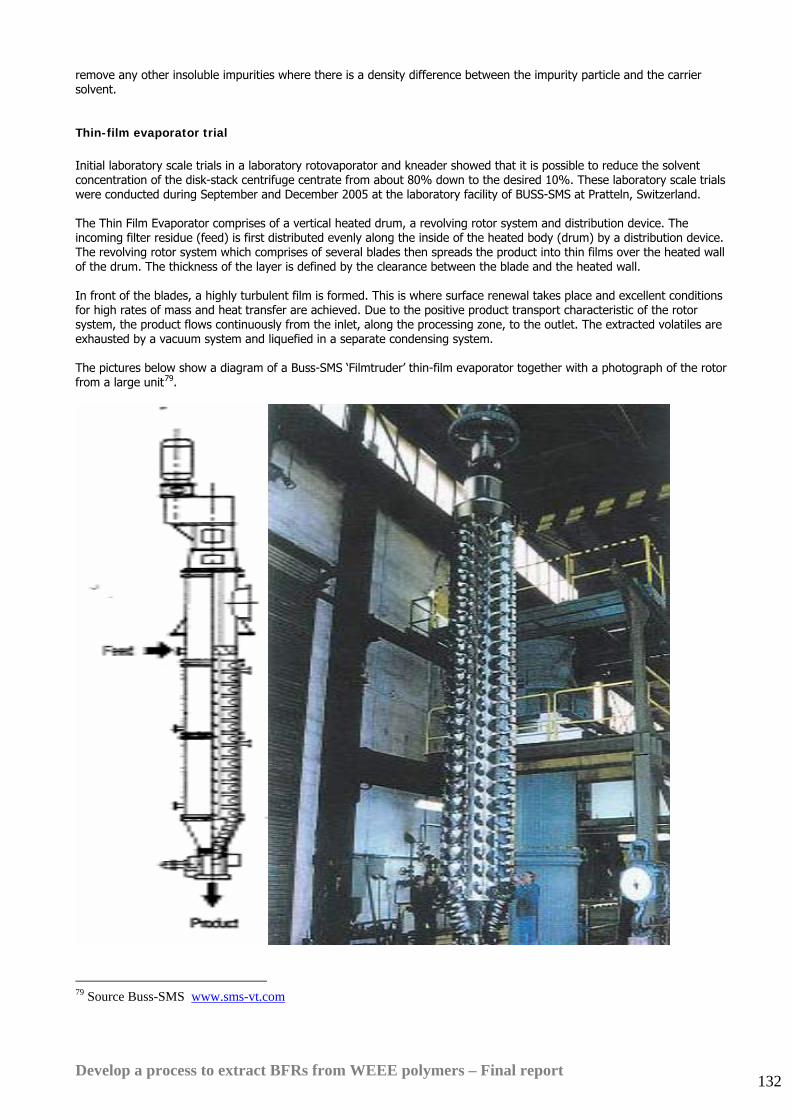
Develop a process to extract BFRs from WEEE polymers – Final report 132
remove any other insoluble impurities where there is a density difference between the impurity particle and the carrier solvent. Thin-film evaporator trial Initial laboratory scale trials in a laboratory rotovaporator and kneader showed that it is possible to reduce the solvent concentration of the disk-stack centrifuge centrate from about 80% down to the desired 10%. These laboratory scale trials were conducted during September and December 2005 at the laboratory facility of BUSS-SMS at Pratteln, Switzerland. The Thin Film Evaporator comprises of a vertical heated drum, a revolving rotor system and distribution device. The incoming filter residue (feed) is first distributed evenly along the inside of the heated body (drum) by a distribution device. The revolving rotor system which comprises of several blades then spreads the product into thin films over the heated wall of the drum. The thickness of the layer is defined by the clearance between the blade and the heated wall. In front of the blades, a highly turbulent film is formed. This is where surface renewal takes place and excellent conditions for high rates of mass and heat transfer are achieved. Due to the positive product transport characteristic of the rotor system, the product flows continuously from the inlet, along the processing zone, to the outlet. The extracted volatiles are exhausted by a vacuum system and liquefied in a separate condensing system. The pictures below show a diagram of a Buss-SMS ‘Filmtruder’ thin-film evaporator together with a photograph of the rotor from a large unit79.
79 Source Buss-SMS www.sms-vt.com
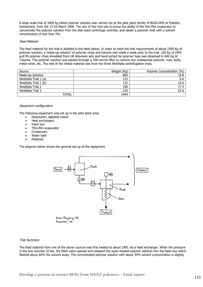
Develop a process to extract BFRs from WEEE polymers – Final report 133
A large scale trial of 2000 kg infeed polymer solution was carried out at the pilot plant facility of BUSS-SMS at Pratteln, Switzerland, from the 13-16 March 2006. The aim of this trial was to prove the ability of the thin-film evaporator to concentrate the polymer solution from the disk-stack centrifuge centrate, and obtain a polymer melt with a solvent concentration of less than 5%. Feed Material The feed material for the trial is detailed in the table below. In order to meet the trial requirements of about 1500 Kg of polymer solution, a ‘made-up solution’ of polymer chips and toluene was made a week prior to the trial. 160 Kg of HIPS and PS polymer chips shredded from UK television sets and hand sorted for polymer type was dissolved in 640 Kg of Toluene. This polymer solution was passed through a 100-micron filter to remove any undissolved polymer, nuts, bolts, metal wires, etc. The rest of the infeed material was from the three Westfalia centrifugation trials. Source Weight (Kg) Polymer Concentration (%) Made-Up Solution 800 19.8 Westfalia Trial 1 (a) 122 9.6 Westfalia Trial 1 (b) 122 15.6 Westfalia Trial 2 190 17.4 Westfalia Trial 3 210 22.0
TOTAL 1444 - Equipment configuration The following equipment was set up in the pilot plant area:
• Dissolution, agitated vessel • Heat exchangers • Flash box • Thin-film evaporator • Condensers • Water bath • Pelletizer
The diagram below shows the general set-up of the equipment.
Trial Summary The feed material from one of the above sources was first heated to about 180C via a heat exchanger. When the pressure in the line reached 10 bar, the flash valve opened and released the super-heated polymer solution into the flash box which flashed about 60% the solvent away. The concentrated polymer solution with about 30% solvent concentration is slightly
Develop a process to extract BFRs from WEEE polymers – Final report 134
cooled, before it enters the thin-film evaporator where it is heated to temperatures up to 250C. More than 99% of the remaining solvent was evaporated in the thin-film evaporator, resulting in a highly concentrated polymer melt with less than 1% solvent concentration. The polymer melt is extruded vertically through a three hole die plate above a water bath which the melt strands pass though before being pelletized in the pelletizer. The throughput of the trial fluctuated due to regulation of the flash valve, but averaged about 180 Kg/h. Both the flash box and the filmtruder operated under vacuum of about 200 mbar. The solvents (toluene) recovered from the flash box and the filmtruder is condensed in separate condensers. The short residence time of the filmtruder helped in preventing the degradation of the polymer due to the high temperatures in the filmtruder. Additionally, stabilizers were also added to ensure that there was no degradation of the polymer due to the high temperatures. The polymer centrate from Westfalia trial 1(a) was passed through the evaporator without any stabilizer to allow for comparison of the effects of the stabilizer on the physical properties of the polymer product. The centrate from Westfalia trial 1(b) was not used at all as the quantity was deemed insufficient. Some of the finished polymer pellets were sent for extrusion trials at PERA. Results Mass balance calculations have shown that about 62% of the recovered solvent was removed by the flash box, while the filmtruder removed the remaining 38% of the recovered solvent for the various infeed materials. A simple weight-loss experiment at PERA prior to the extrusion trials showed that the solvent content in the pellets (polymer melt from filmtruder) was as low as 0.07%. This is a 99.7% reduction in solvent concentration from an input polymer solution with a solvent concentration of about 80%. Conclusions for the thin-film evaporator trial Although the flash box and the thin-film evaporator has a high capital cost, it achieves such a good solvent removal rate that it eliminates the need for a vented extruder to remove further solvent, and only requires a pelletizer to make polymer pellets for sale. Solvent recovery trial The technology used in the solvent recovery section of this process is similar to that used in the solvent recovery section of the Creasolv Process. Thus, a description of the equipment used in the trial and an explanation of the workings of the equipment and technology is available in the Solvent recovery trial section of the Creasolv Process Trials summary. Two solvent recovery trials were carried out in November 2005 and March 2006. The first solvent recovery trial was to establish that the solvent recovery unit was able to recover the solvent (toluene) and also produce a dry residue, suitable for landfill. The second trial was to experiment with another drying agent which is a ‘low-cost waste by-product’ of another industry as an alternative to the recommended drying agent. The recommended drying agent was a food-grade additive and this is costly. The main difference in the two trials was the drying agent used. Feed material The first trial used the disk-stack centrifuge residue from Westfalia trial 1. This contained a polymer solution made using HIPS golden sample dissolved in toluene, concentrated in antimony and slightly in bromine. The second used the disk-stack centrifuge residue from Westfalia trial 3. This contained a polymer solution made using HIPS and PS from UK television sets dissolved in toluene, and also concentrated in antimony and bromine. The significantly
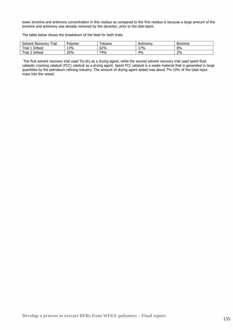
Develop a process to extract BFRs from WEEE polymers – Final report 135
lower bromine and antimony concentration in this residue as compared to the first residue is because a large amount of the bromine and antimony was already removed by the decanter, prior to the disk-stack. The table below shows the breakdown of the feed for both trials. Solvent Recovery Trial Polymer Toluene Antimony Bromine Trial 1 Infeed 13% 62% 17% 8% Trial 2 Infeed 20% 74% 4% 2% The first solvent recovery trial used Tix-dry as a drying agent, while the second solvent recovery trial used spent fluid catalytic cracking catalyst (FCC) catalyst as a drying agent. Spent FCC catalyst is a waste material that is generated in large quantities by the petroleum refining industry. The amount of drying agent added was about 7%-10% of the total input mass into the vessel.
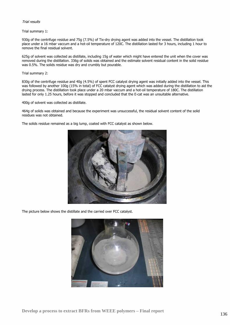
Develop a process to extract BFRs from WEEE polymers – Final report 136
Trial results Trial summary 1: 930g of the centrifuge residue and 75g (7.5%) of Tix-dry drying agent was added into the vessel. The distillation took place under a 16 mbar vaccum and a hot-oil temperature of 120C. The distillation lasted for 3 hours, including 1 hour to remove the final residual solvent. 625g of solvent was collected as distillate, including 15g of water which might have entered the unit when the cover was removed during the distillation. 336g of solids was obtained and the estimate solvent residual content in the solid residue was 0.5%. The solids residue was dry and crumbly but pourable. Trial summary 2: 830g of the centrifuge residue and 40g (4.5%) of spent FCC catalyst drying agent was initially added into the vessel. This was followed by another 100g (15% in total) of FCC catalyst drying agent which was added during the distillation to aid the drying process. The distillation took place under a 20 mbar vaccum and a hot-oil temperature of 180C. The distillation lasted for only 1.25 hours, before it was stopped and concluded that the E-cat was an unsuitable alternative. 400g of solvent was collected as distillate. 464g of solids was obtained and because the experiment was unsuccessful, the residual solvent content of the solid residues was not obtained. The solids residue remained as a big lump, coated with FCC catalyst as shown below.
The picture below shows the distillate and the carried over FCC catalyst.
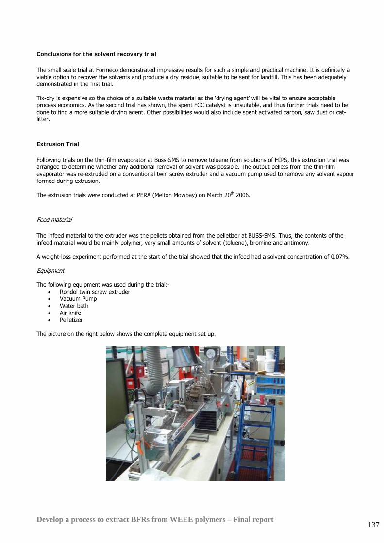
Develop a process to extract BFRs from WEEE polymers – Final report 137
Conclusions for the solvent recovery trial The small scale trial at Formeco demonstrated impressive results for such a simple and practical machine. It is definitely a viable option to recover the solvents and produce a dry residue, suitable to be sent for landfill. This has been adequately demonstrated in the first trial. Tix-dry is expensive so the choice of a suitable waste material as the ‘drying agent’ will be vital to ensure acceptable process economics. As the second trial has shown, the spent FCC catalyst is unsuitable, and thus further trials need to be done to find a more suitable drying agent. Other possibilities would also include spent activated carbon, saw dust or cat-litter. Extrusion Trial Following trials on the thin-film evaporator at Buss-SMS to remove toluene from solutions of HIPS, this extrusion trial was arranged to determine whether any additional removal of solvent was possible. The output pellets from the thin-film evaporator was re-extruded on a conventional twin screw extruder and a vacuum pump used to remove any solvent vapour formed during extrusion. The extrusion trials were conducted at PERA (Melton Mowbay) on March 20th 2006. Feed material The infeed material to the extruder was the pellets obtained from the pelletizer at BUSS-SMS. Thus, the contents of the infeed material would be mainly polymer, very small amounts of solvent (toluene), bromine and antimony. A weight-loss experiment performed at the start of the trial showed that the infeed had a solvent concentration of 0.07%. Equipment The following equipment was used during the trial:-
• Rondol twin screw extruder • Vacuum Pump • Water bath • Air knife • Pelletizer
The picture on the right below shows the complete equipment set up.
Develop a process to extract BFRs from WEEE polymers – Final report 138
Trial Summary The infeed pellets were fed into the extruder and heated to a temperature of up to 180C. As they passed the vacuum port (-0.69 bar), any excess solvent would be evaporated. There were no fumes observed at the extruder die, but a very faint toluene odour was observed at the outlet of the vacuum pump and in the extruded pellets. Results A similar weight-loss experiment, whereby the extruded materials were stored in a vented oven at 80oC for two hours showed that after the extrusion, the solvent content of the polymer was about 0.034%. This showed a solvent content reduction of about 50% from the initial 0.07%. Conclusions for the extrusion trial As the input to the extruder from the thin-film evaporator has such a low solvent content, the amount of solvent that the extrusion process actually removes will be very small, as compared to the large capital cost required to acquire an extruder. Furthermore, the output from the thin-film evaporator being at 0.07% has already met the target solvent concentration of less than 1%, so an additional extruder would not significantly improve the product performance.
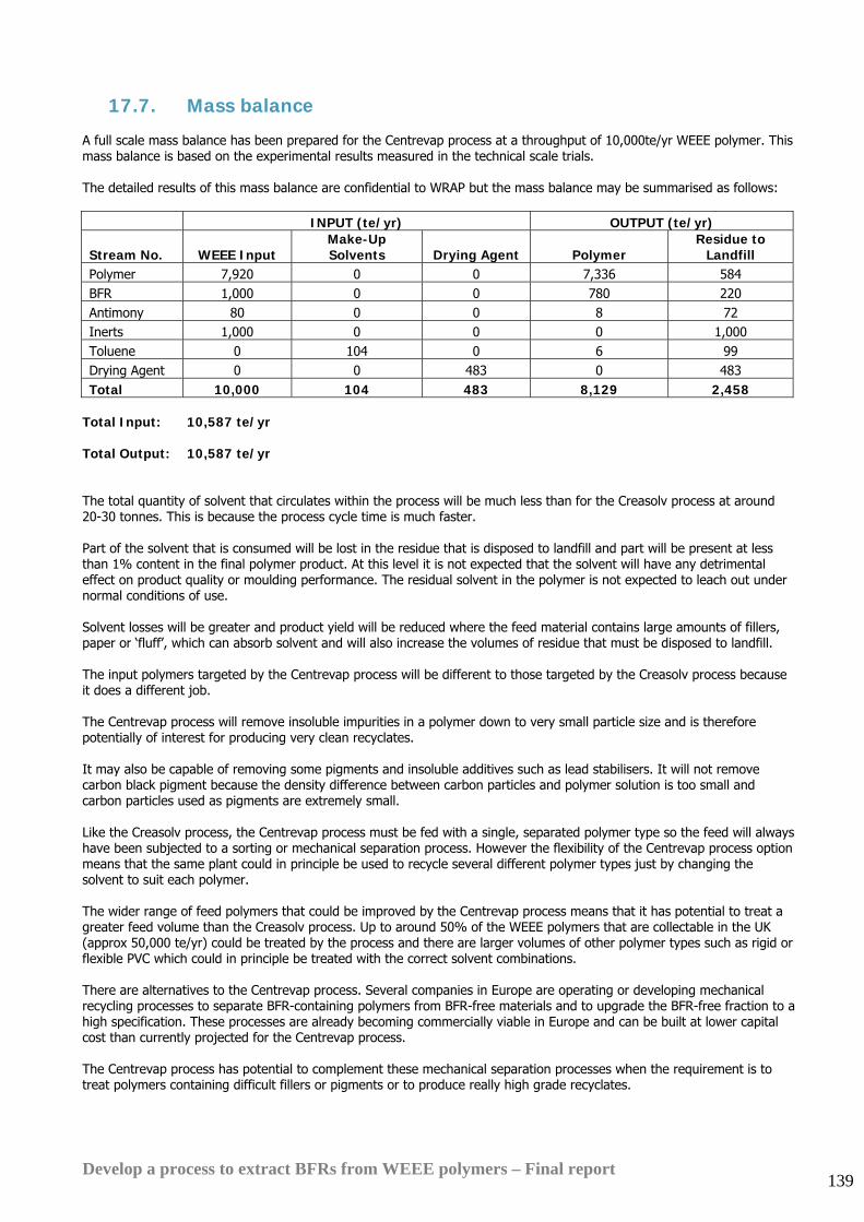
Develop a process to extract BFRs from WEEE polymers – Final report 139
17.7. Mass balance
A full scale mass balance has been prepared for the Centrevap process at a throughput of 10,000te/yr WEEE polymer. This mass balance is based on the experimental results measured in the technical scale trials. The detailed results of this mass balance are confidential to WRAP but the mass balance may be summarised as follows: INPUT (te/yr) OUTPUT (te/yr)
Stream No. WEEE Input Make-Up Solvents Drying Agent Polymer
Residue to Landfill
Polymer 7,920 0 0 7,336 584 BFR 1,000 0 0 780 220 Antimony 80 0 0 8 72 Inerts 1,000 0 0 0 1,000 Toluene 0 104 0 6 99 Drying Agent 0 0 483 0 483 Total 10,000 104 483 8,129 2,458
Total Input: 10,587 te/yr Total Output: 10,587 te/yr The total quantity of solvent that circulates within the process will be much less than for the Creasolv process at around 20-30 tonnes. This is because the process cycle time is much faster. Part of the solvent that is consumed will be lost in the residue that is disposed to landfill and part will be present at less than 1% content in the final polymer product. At this level it is not expected that the solvent will have any detrimental effect on product quality or moulding performance. The residual solvent in the polymer is not expected to leach out under normal conditions of use. Solvent losses will be greater and product yield will be reduced where the feed material contains large amounts of fillers, paper or ‘fluff’, which can absorb solvent and will also increase the volumes of residue that must be disposed to landfill. The input polymers targeted by the Centrevap process will be different to those targeted by the Creasolv process because it does a different job. The Centrevap process will remove insoluble impurities in a polymer down to very small particle size and is therefore potentially of interest for producing very clean recyclates. It may also be capable of removing some pigments and insoluble additives such as lead stabilisers. It will not remove carbon black pigment because the density difference between carbon particles and polymer solution is too small and carbon particles used as pigments are extremely small. Like the Creasolv process, the Centrevap process must be fed with a single, separated polymer type so the feed will always have been subjected to a sorting or mechanical separation process. However the flexibility of the Centrevap process option means that the same plant could in principle be used to recycle several different polymer types just by changing the solvent to suit each polymer. The wider range of feed polymers that could be improved by the Centrevap process means that it has potential to treat a greater feed volume than the Creasolv process. Up to around 50% of the WEEE polymers that are collectable in the UK (approx 50,000 te/yr) could be treated by the process and there are larger volumes of other polymer types such as rigid or flexible PVC which could in principle be treated with the correct solvent combinations. There are alternatives to the Centrevap process. Several companies in Europe are operating or developing mechanical recycling processes to separate BFR-containing polymers from BFR-free materials and to upgrade the BFR-free fraction to a high specification. These processes are already becoming commercially viable in Europe and can be built at lower capital cost than currently projected for the Centrevap process. The Centrevap process has potential to complement these mechanical separation processes when the requirement is to treat polymers containing difficult fillers or pigments or to produce really high grade recyclates.
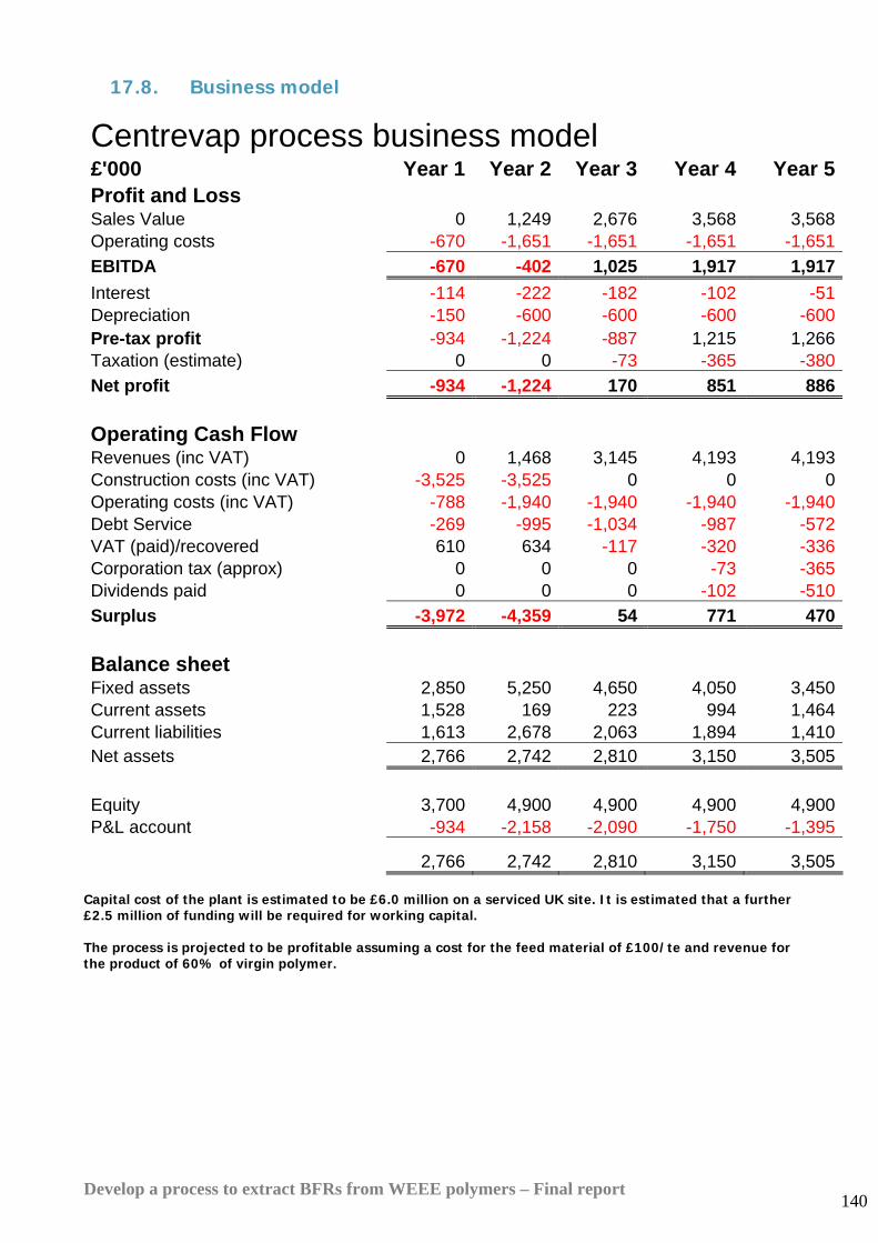
Develop a process to extract BFRs from WEEE polymers – Final report 140
17.8. Business model
Centrevap process business model
£'000 Year 1 Year 2 Year 3 Year 4 Year 5Profit and Loss Sales Value 0 1,249 2,676 3,568 3,568Operating costs -670 -1,651 -1,651 -1,651 -1,651EBITDA -670 -402 1,025 1,917 1,917Interest -114 -222 -182 -102 -51Depreciation -150 -600 -600 -600 -600Pre-tax profit -934 -1,224 -887 1,215 1,266Taxation (estimate) 0 0 -73 -365 -380Net profit -934 -1,224 170 851 886
Operating Cash Flow Revenues (inc VAT) 0 1,468 3,145 4,193 4,193Construction costs (inc VAT) -3,525 -3,525 0 0 0Operating costs (inc VAT) -788 -1,940 -1,940 -1,940 -1,940Debt Service -269 -995 -1,034 -987 -572VAT (paid)/recovered 610 634 -117 -320 -336Corporation tax (approx) 0 0 0 -73 -365Dividends paid 0 0 0 -102 -510Surplus -3,972 -4,359 54 771 470
Balance sheet Fixed assets 2,850 5,250 4,650 4,050 3,450Current assets 1,528 169 223 994 1,464Current liabilities 1,613 2,678 2,063 1,894 1,410Net assets 2,766 2,742 2,810 3,150 3,505 Equity 3,700 4,900 4,900 4,900 4,900P&L account -934 -2,158 -2,090 -1,750 -1,395
2,766 2,742 2,810 3,150 3,505 Capital cost of the plant is estimated to be £6.0 million on a serviced UK site. It is estimated that a further £2.5 million of funding will be required for working capital. The process is projected to be profitable assuming a cost for the feed material of £100/te and revenue for the product of 60% of virgin polymer.
Develop a process to extract BFRs from WEEE polymers – Final report 141
17.9. Discussion As for the Creasolv process the projected recycled polymer price has been increased by £124/te to £560/te (60% of the virgin polymer price) because consultations with manufacturers have demonstrated increasing interest in high grade recycled content.
In the case of the Centrevap process it is assumed that the process operators will have to pay £100/te for the infeed material in competition with exports to China because this process will not remove BFRs and it is therefore only suitable for upgrading substantially BFR-free polymer. Note that this is different to the Creasolv process where a gate fee of £45/te in competition with landfill is assumed.
At a recycled polymer price of 60% of virgin and a cost of £100/te for the input material (to compete with export to China) it makes a satisfactory return for investors. These are the results shown above.
At a higher recyclate price of 80% of virgin polymer it makes very attractive returns and the project internal rate of return rises from 16% to 40%.
However there is a fundamental difference in the performance of the two process options. The Creasolv process will remove BFRs down to the target level of 0.1% while the Centrevap process will not.
Concerns regarding the Centrevap process remain. They include:
• It will not be effective for removing brominated flame retardants.
• As for Creasolv the economics of the Centrevap process depend heavily on being able to recover virtually all of the solvent used in the process. The recovery rate predicted by the process mass balance is better than 98%. Test work conducted for this project indicates that this level of recovery should be achievable with good quality process design around the solvent recovery and vacuum systems.
• The process design and business model have been developed with HIPS as the target polymer and toluene as the chosen solvent. To dissolve ABS or ABS/PC more expensive solvents such as dichloromethane, dimethyl formamide or tetrahydrofuran will be required. Provided the level of solvent losses can be tightly controlled as envisaged in the current mass balance the extra cost of these solvents should not affect commercial viability.
• The volatile solvents used by Centrevap are more flammable than the Creasolv solvents and will create VOC emissions more readily
However there are some important factors in favour of this process option if the process objective is to produce high grade polymer, free of insoluble contaminants:
• The process sequence is simple and should be relatively easy to control on a truly continuous basis
• The evaporation technique used is well established at bulk scale for virgin polymers
• The low boiling solvents proposed are easier to remove than the higher boiling solvents used by Creasolv
• Residence time for material passing through the system will be short, requiring low process inventories and helping to limit polymer degradation
• The process will be capable of processing any soluble polymer to remove all insoluble additives, not just BFRs. Initial tests have been made at lab scale with unplasticised PVC and these appear to be promising.
• Energy consumption and operating cost for the Centrevap process are now lower than for Creasolv because of changes made to the Creasolv process in order to achieve maximum BFR reduction
• Although the Centrevap process capital cost has increased since the first process design was completed as a result of the introduction of a second centrifuge step, the estimated capital cost and working capital requirement is now lower than for Creasolv because the Creasolv plant cost has also increased substantially.
• The maximum insoluble particle size left in the product from the Centrevap process will be submicron. The maximum particle size left by the Creasolv process will be limited to the 50-100micron range by the primary filter used at the start of the process.
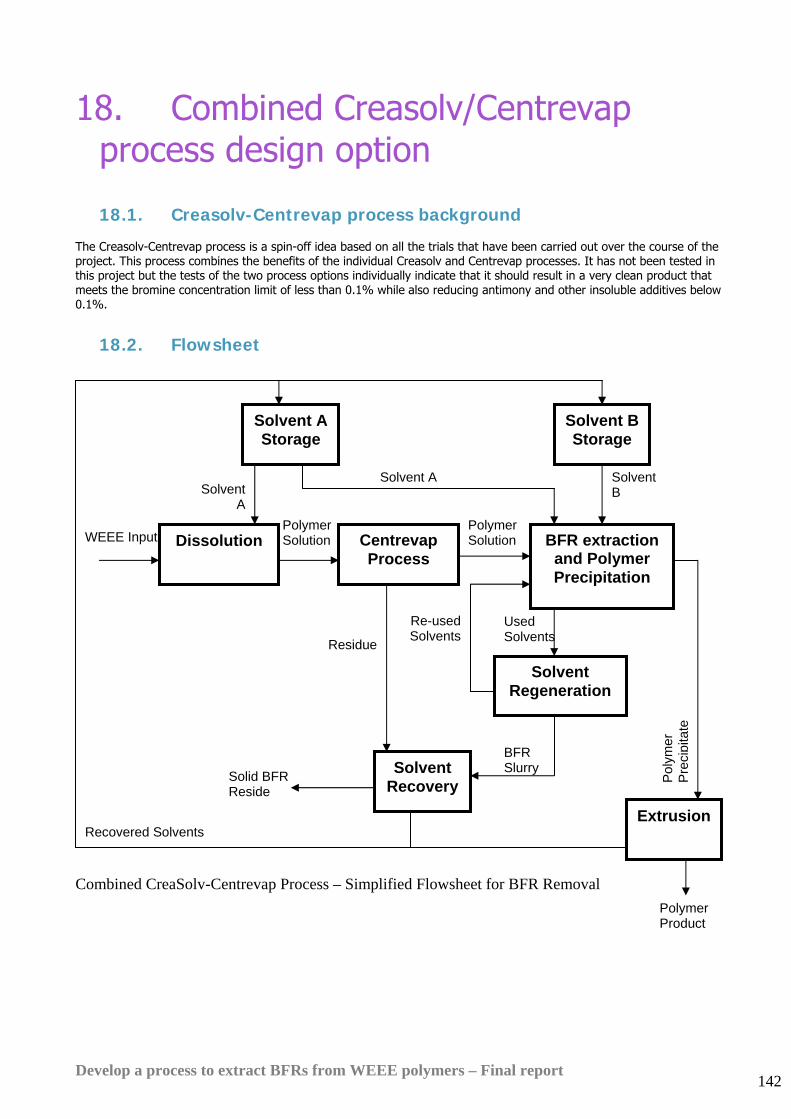
Develop a process to extract BFRs from WEEE polymers – Final report 142
18. Combined Creasolv/Centrevap process design option
18.1. Creasolv-Centrevap process background The Creasolv-Centrevap process is a spin-off idea based on all the trials that have been carried out over the course of the project. This process combines the benefits of the individual Creasolv and Centrevap processes. It has not been tested in this project but the tests of the two process options individually indicate that it should result in a very clean product that meets the bromine concentration limit of less than 0.1% while also reducing antimony and other insoluble additives below 0.1%.
18.2. Flowsheet
Combined CreaSolv-Centrevap Process – Simplified Flowsheet for BFR Removal
Used Solvents
Recovered Solvents
Solvent Recovery
BFR Slurry Solid BFR
Reside
Solvent Regeneration
Residue
Re-used Solvents
Solvent A Storage
Dissolution Centrevap Process
WEEE Input
Solvent A
Solvent A
Polymer Solution
Polymer Solution
Solvent B Storage
BFR extraction and Polymer Precipitation
Extrusion
Solvent B
Pol
ymer
P
reci
pita
te
Polymer Product
Develop a process to extract BFRs from WEEE polymers – Final report 143
18.3. Process description The Creasolv-Centrevap Process is a batch process which uses a high boiling point solvent to dissolve the feed plastic.
Combination with the Centrevap process at this stage results in the removal of all impurities, such as antimony, fillers and additives that are more than 0.3 microns.
A series of precipitation steps follow using a combination of proprietary Creasolv solvents. These reduce the bromine content in the polymer to less than 0.1%.
The BFRs are extracted into the solvents and the solvents are recovered by distillation.
The main steps in the process are dissolution, impurity removal, a series of extractions and extrusion of the final product.
Input feed material
The input feed material to the plant consists of shredded plastic waste of approximate size between 30-50 mm. The plastic waste should be pre-sorted so that it is primarily HIPS and ABS.
Dissolution
Regenerated Creasolv solvent from previous batches is stored under ambient conditions in a carbon steel storage tank ready for use in the dissolution process.
A jacketed-dissolution vessels is filled with Creasolv solvent and heated via the heating jacket. The polymer is added. At elevated temperature, the polymer and BFRs are both soluble in the hot Creasolv.
Impurity removal
Any undissolved polymers and other insoluble impurities are removed by filtration and centrifuges, similar to that in the Centrevap process. A pump draws from the dissolution vessels to feed the filters. The centrifuge centrate contains the dissolved polymer, soluble additives, and any impurities less than 0.3 microns in size. The residue contains the undissolved polymer, insoluble additives and inerts such as paper, fluff and metals.
BFR extraction and polymer precipitation
The filtered solution from the dissolution vessel is pumped into a solvent extraction unit. A second proprietary Creasolv solvent is added. This causes the polymer and the BFRs to separate.
The bulk of the excess solvent is removed from the debrominated polymer in a series of special extraction units. The recovered solvent mixture is pumped to store tanks and then passed to a special solvent regeneration unit.
Solvent regeneration
A novel solvent regeneration process has been developed as a result of the collaboration between WRAP and Fraunhofer IVV. This process separates the BFRs from the two Creasolv extract solvents and separates the solvents from each other ready for re-use
BFRs are recovered by the solvent regeneration unit as a concentrated bromine-rich slurry. This slurry is passed to the final solvent recovery unit along with the filter residues from the first stage of the process.
Extrusion
The polymer gel particles from the extraction/ precipitation step are passed to a vacuum vented twin screw extruder for removal of the remaining solvent down to about 1%. The polymer product is cooled in a water bath and pelletized.
Additives and masterbatch can be added at this stage to modify the final polymer properties if required.
The solvents removed during extraction are returned to the solvent regeneration unit for recovery
Final solvent Recovery Unit
The Solvent Recovery Unit receives slurries from the filters and the solvent regeneration unit. It processes these slurries separately batch-wise and recovers almost all the solvents by heating under vacuum, resulting in a dry, free-flowing bromine-rich inert residue which is safe for disposal to landfill.
The bromine industry may be interested in taking the bromine-rich fraction from the solvent regeneration unit as a source of bromine feedstock in which case it may also be diverted from landfill.
The mixed solvents that are recovered by this unit are also returned to the solvent regeneration process.
Develop a process to extract BFRs from WEEE polymers – Final report 144
ENERGY USED
• Hot utility requirement (Low Pressure Steam- 5 bar): 4.7 te of steam/te feed
• Cold utility requirement (Cold Water): 60.5 te/te feed
• Power (Average Draw): 214 kWh/te feed
EFFLUENTS PRODUCED
Water Effluent
None
Vapour Effluent
The extruder producing the final polymer and the final solvent recovery unit will both generate small quantities of solvent emissions to atmosphere via the vacuum system. The great majority of these emissions can be controlled by a cold trap fitted on the input side of the vac pump, particularly as the Creasolv solvents have high boiling points. Any residual emissions from the vacuum pump can be eliminated by means of a biological filter if required.
Solids
BFR is discharged from the process in slurry in Creasolv solvent. The solvent is recovered and recycled from the slurry by the solvent recovery unit as a dry free-flowing powder.
Solid wastes are also produced from the primary filter residue at the solvent recovery unit. The solids will be discharged as a dry cake and transported from site for landfill disposal.
18.4. Mass balance A full scale mass balance has been prepared for the Creasolv-Centrevap process at a throughput of 10,000te/yr WEEE polymer. This mass balance is based on the experimental results measured in the technical scale trials. The detailed results of this mass balance are confidential but the mass balance may be summarised as follows: INPUT (te/yr) OUTPUT (te/yr)
Stream No. WEEE Input Make-Up Solvents Drying Agent Polymer Residue to Landfill
Polymer 7,920 0 0 7,534 386 BFR 1,000 0 0 3 997 Antimony 80 0 0 0 80 Inerts 1,000 0 0 0 1,000 Solvents 0 155 0 38 117 Drying Agent 0 0 582 0 582 Total 10,000 155 582 7,575 3,162
Total Input: 10,737 te/yr Total Output: 10,737 te/yr Part of the solvent that is consumed will be lost in the residue that is disposed to landfill and part will be present at less than 1% in the final polymer product. At this level it is not expected that the solvent will have any detrimental effect on product quality or moulding performance. The residual solvent in the product is non-toxic.
Develop a process to extract BFRs from WEEE polymers – Final report 145
18.5. Discussion As can be seen from the large scale trials, the Centrevap process is unable to attain the target bromine concentration of less than 0.1%. However, it is able to reduce the antimony concentration significantly, down to at least 0.14%. This is because the centrifuges mainly perform a physical separation. As the BFRs are partially soluble in toluene at high temperatures, the centrifuges are unable to remove a significant amount to meet the target concentration. On the other hand, the antimony being completely insoluble achieves higher reduction rates as the centrifuges are able to remove anything above 0.3 microns.
The Creasolv process is a chemical separation process, and is able to achieve the target bromine concentration through the preferential solution of BFRs in its solvents. It is unable to reduce the antimony concentration as the antimony is mainly removed via redistribution in the used solvents. The bottleneck in the Creasolv process in this aspect is that the purity of the polymer product is dependent on the size of the filters in the process. In this design, the filter mesh is sized at 100 microns. Thus, any impurities in the polymer such as additives and fillers that are smaller than 100 microns have a high chance or re-emerging in the final product.
By combining the two processes, a polymer product with extremely low impurities (0.3 microns) and a low bromine concentration of less than 0.1% can be obtained.
Cost estimation for this option indicates that the capital cost will be higher at £14m, compared to £11.8 million for the standard Creasolv process. This is mainly due to addition of the two high cost centrifuges to the process flowsheet.
As a result the financial returns for the combined Creasolv-Centrevap process will be significantly lower than for the conventional Creasolv process option. The process will not be commercially viable at a price of 60% of virgin polymer but it will make money at 80% of virgin polymer price.
The higher price level will be more easily achievable if the polymer solution is centrifuged prior to bromine extraction. Centrifuging will ensure no insoluble impurities above 2-3 micron size, compared to 50-100 micron for the standard Creasolv process. This will improve extrusion performance, appearance and impact strength of the final polymer material.
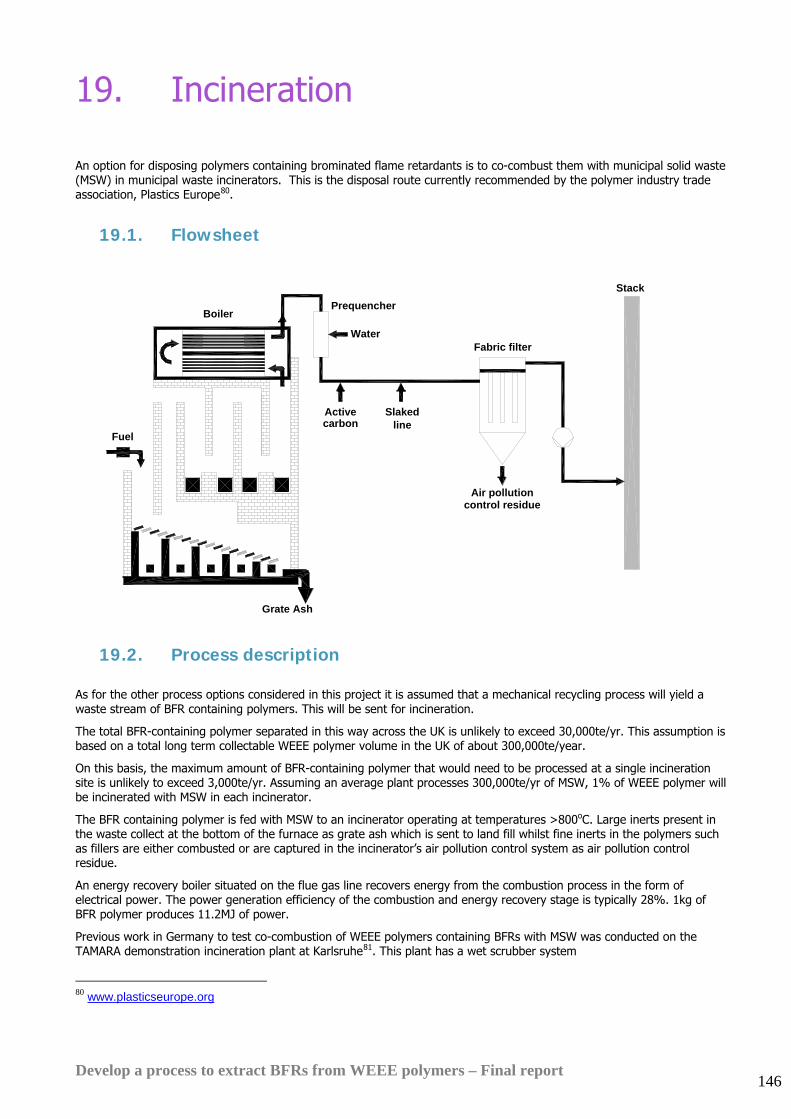
Develop a process to extract BFRs from WEEE polymers – Final report 146
19. Incineration
An option for disposing polymers containing brominated flame retardants is to co-combust them with municipal solid waste (MSW) in municipal waste incinerators. This is the disposal route currently recommended by the polymer industry trade association, Plastics Europe80.
19.1. Flowsheet
Boiler
Fuel
Fabric filter
PrequencherStack
Air pollution
Grate Ash
Water
SlakedActivecarbon line
control residue
19.2. Process description
As for the other process options considered in this project it is assumed that a mechanical recycling process will yield a waste stream of BFR containing polymers. This will be sent for incineration.
The total BFR-containing polymer separated in this way across the UK is unlikely to exceed 30,000te/yr. This assumption is based on a total long term collectable WEEE polymer volume in the UK of about 300,000te/year.
On this basis, the maximum amount of BFR-containing polymer that would need to be processed at a single incineration site is unlikely to exceed 3,000te/yr. Assuming an average plant processes 300,000te/yr of MSW, 1% of WEEE polymer will be incinerated with MSW in each incinerator.
The BFR containing polymer is fed with MSW to an incinerator operating at temperatures >800oC. Large inerts present in the waste collect at the bottom of the furnace as grate ash which is sent to land fill whilst fine inerts in the polymers such as fillers are either combusted or are captured in the incinerator’s air pollution control system as air pollution control residue.
An energy recovery boiler situated on the flue gas line recovers energy from the combustion process in the form of electrical power. The power generation efficiency of the combustion and energy recovery stage is typically 28%. 1kg of BFR polymer produces 11.2MJ of power.
Previous work in Germany to test co-combustion of WEEE polymers containing BFRs with MSW was conducted on the TAMARA demonstration incineration plant at Karlsruhe81. This plant has a wet scrubber system
80 www.plasticseurope.org
Develop a process to extract BFRs from WEEE polymers – Final report 147
Most UK waste incinerators do not use wet scrubbers to catch pollutants. All of the latest and largest plants use dry air pollution control systems.
About 50% of UK plants use slaked lime (calcium hydroxide) emulsion injection followed by activated carbon injection followed by bag filters.
The water in the slaked lime emulsion evaporates as it contacts the raw incinerator flue gas, cooling the gas to the temperature that the bag filters can withstand. The water in the emulsion also provides a reaction medium for contact between the slaked lime and the flue gas acids.
The other 50% of UK plants use dry quicklime and activated carbon injection followed by water injection to cool the flue gases before the bag filters.
The chemical reactions involved are essentially the same in both cases:
CaO + 2HCl = CaCl2 + H2O
Or Ca(OH)2 + 2HCl = CaCl2 + 2H2O
Activated carbon is injected in relatively small quantities and its function is to capture cadmium, mercury and other volatile heavy metals plus any dioxins and other residual organic species in the flue gas.
After passing through the boiler the HCl and HBr content of the raw flue gas is neutralised by the injection of a slaked lime-water slurry. Activated carbon is also injected with the slurry to absorb heavy metals, dioxins and furans. The water in the slurry acts as a coolant reducing the temperature of the gas by approximately 100oC to 150oC to prevent damage to the bag filter in the next stage of the process.
Finally the flue gas passes through a filter bag which recovers solid particulates from the gas before its release to atmosphere.
The filtrate recovered contains fine inerts, calcium halides and carbon and is known as ‘Air pollution control residue’ (APC). The APC residue is then treated and disposed of as hazardous waste. It is classed as hazardous waste due to its irritant properties resulting from its large lime concentration.
Energy Generation
3.1 MWhr of electrical power/te of BFR incinerated
Effluents Produced
Water
None, Water evaporates and leaves the process with the flue gas.
Vapour
The vapour contains the burned polymers, inerts and the bromine free BFRs.
Solids
Grate ash collects in the bottom of the furnace after the combustion stage. This grate ash contains inerts which are subsequently sent to landfill.
APC residue is captured in the bag filter. The residue is made up of lime, calcium halides, carbon and fine inerts. The residue is classed as an irritant therefore must be disposed of as hazardous waste.
Emission quantities (based on polymer feed rate of 1429Kg/hr):
Kg/hr Grate ash
Air pollution control residue
Inerts 11 4
Activated carbon 75
Calcium bromide formed by reaction between lime and BFR combustion products plus unreacted excess lime added to ensure complete scrubbing
264
Total 11 343
81 ‘Recycling of Bromine from plastics containing brominated flame retardants in state-of-the-art combustion facilities’, Vehlow J, Hunsinger H, Bergfelt B, Jay K, Mark F, Tange L, Drohmann D, Fisch H, APME Technical paper
Develop a process to extract BFRs from WEEE polymers – Final report 148
19.3. Business model There is no additional capital cost associated with this process as it will take place at an existing incinerator site. The cost of providing the incineration plant is taken into account in the gate fee charged by the incinerator operator to its suppliers of feed material.
The calorific value of WEEE polymers (40MJ/kg) is approximately four times the value of that for MSW (10MJ/kg).
Incinerator economics are based primarily around charging a gate fee for incoming material. This is supplemented by the value of power generated from steam generated in the incinerator waste heat boiler.
The power generation systems of UK MSW incinerators are sized for a calorific value of 10MJ/kg.
Burning high calorific value material such as WEEE polymer generates about four times more heat per tonne than burning MSW. Provided the incinerator is running at full capacity WEEE polymers will therefore displace four times the mass of MSW being incinerated.
To maintain the revenue of the incineration plant the gate fee that the incinerator must charge in order to cover its capital and operating costs must be four times higher for WEEE polymer than for MSW (~£180/te compared to ~£45/te for MSW).
Further extra incineration costs are incurred when burning BFR-containing polymers as a result of;
• a larger quantity of lime being required: 112Kg/te for BFR polymer compared to 6.5Kg/te for MSW (adds cost of about £12/te BFR polymer)
• disposing the Air Pollution Control (APC) residue to hazardous waste landfill: 200Kg/te for BFR polymer compared to 17Kg/te for MSW(adds cost of about £17/te BFR polymer)
For this model it is assumed that no additional activated carbon would need to be added to capture additional brominated dioxin equivalents that would be generated as a result of combustion of BFR polymers. If additional carbon would need to be added this would increase the cost for carbon and also the APC residue disposal cost.
Summary of costs:
£/te BFR feed
Gate fee charged by MSW incinerator for BFR polymer in order to maintain incinerator revenue 180
Additional lime cost compared to MSW 12
Additional hazardous waste landfill cost compared to MSW 17
Total additional cost 209
This analysis indicates that incineration of BFR polymer with energy recovery as a 1% addition to the feed to existing large scale MSW incinerators in the UK would have a net cost around £209/te. This is £164/te more than the £45/te gate fee assumed for the other process options considered in this project.
Note that £45/te was chosen as the reference gate fee as this is the current UK landfill cost. Landfill is therefore a much less expensive disposal option for BFR-containing polymers than incineration with energy recovery in the UK context.
Develop a process to extract BFRs from WEEE polymers – Final report 149
19.4. Discussion All UK MSW incinerators are required by the Waste Incineration Directive (WID) to achieve a minimum flue gas temperature of 850C.
The WID requires that some wastes are incinerated at higher temperatures with a minimum flue gas temperature of 1100C.
The specifications for materials which require higher temperature incineration are set out in the European Waste Catalogue section of DEFRA’s guidance note on the WID82. This guidance indicates that WEEE polymers containing BFRs would almost certainly be required by the WID to be processed at 1100C even though plastics are cleared for combustion at 850C. This is because the European waste catalogue specifies that wastes containing dangerous substances as specified in the European Directive on classification, packaging and labelling of dangerous substances 67/548/EEC83 must be incinerated at the higher temperature.
Most mixtures of WEEE polymers will contain some octa or penta BDE, which are classified as dangerous substances and would therefore qualify for the higher incineration temperature. However any incinerator operator that considers burning WEEE polymers containing BFRs may be able to negotiate with the regulators that the BFR-containing polymers are not dangerous because the BFRs are locked in the polymer matrix
If the 1100C temperature is required then this would mean that bulk Municipal Solid Waste (MSW) incinerators could not be used to co-combust BFR-containing polymers in the UK. Instead, more expensive dedicated incinerators for dangerous wastes would be required.
UK incinerators are usually only licensed by their local authority to burn MSW collected in their local area as import of waste for incineration is a political ‘hot potato’. This would need to be taken into account when considering the commercial viability of an incineration strategy for WEEE polymers containing BFRs.
The incineration of Bromine-containing compounds can increase the corrosion rate of an incinerator. The corrosion of boiler parts has been related to a combination of relatively high halogen levels, high temperatures in the flue gas and deposits on heat transfer surfaces. Corrosion mechanisms include deposit build up, evaporation of metal chlorides, and melting of salt deposits84.
APC residue is treated as hazardous waste because it is an irritant due to the large excess of lime that it contains.
Normal APC residue contains about 15% chlorides. The soluble halide content of air pollution control residue leaches in landfills and will not meet the landfill directive hazardous waste acceptance criteria which came into force on July 16th 2005.
The leaching criteria for non-hazardous landfills are not as onerous as for hazardous landfills so the strategy likely to be adopted in future by incinerators is to neutralize the excess lime with an acid such as HCl or H2SO4 so that the irritant nature is lost and the material can be disposed to non-hazardous landfill. This will increase neutralization cost and the total waste volume but will reduce disposal cost/te because non-hazardous landfill is less expensive.
At present UK incinerators would have to charge extra gate fees to accept high calorific value material in order to maintain their current revenue levels. However experience in the Netherlands and elsewhere in Northern Europe where recycling levels are significantly higher than in the UK indicates that as municipal waste recycling improves, the calorific value of the MSW stream reduces below 10MJ/Kg. When this happens incinerators are happier to accept high CV material with no additional gate fee in order to maintain their heat balance. We are still some way from this position in the UK.
82 http://www.defra.gov.uk/environment/ppc/wasteincin/pdf/wid-guidance-edition3.pdf 83 http://ec.europa.eu/environment/dansub/main67_548/index_en.htm 84 Rademakers. P, et al, Review of corrosion in waste incinerators, and possible effects of bromine, 2002 http://www.ebfrip.org/statements/TNO-AKZO-corrosion-study2002-Final.pdf
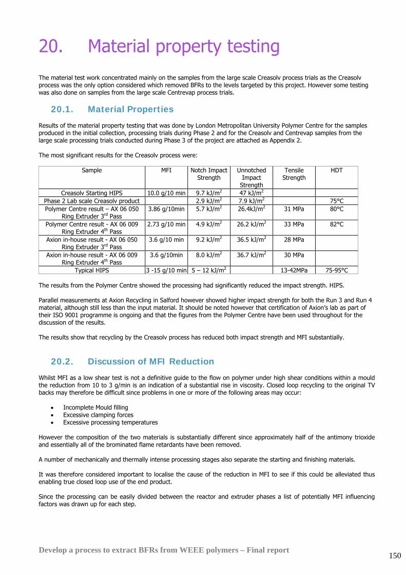
Develop a process to extract BFRs from WEEE polymers – Final report 150
20. Material property testing
The material test work concentrated mainly on the samples from the large scale Creasolv process trials as the Creasolv process was the only option considered which removed BFRs to the levels targeted by this project. However some testing was also done on samples from the large scale Centrevap process trials.
20.1. Material Properties Results of the material property testing that was done by London Metropolitan University Polymer Centre for the samples produced in the initial collection, processing trials during Phase 2 and for the Creasolv and Centrevap samples from the large scale processing trials conducted during Phase 3 of the project are attached as Appendix 2. The most significant results for the Creasolv process were:
Sample MFI Notch Impact Strength
Unnotched Impact
Strength
Tensile Strength
HDT
Creasolv Starting HIPS 10.0 g/10 min 9.7 kJ/m2 47 kJ/m2 Phase 2 Lab scale Creasolv product 2.9 kJ/m2 7.9 kJ/m2 75°C Polymer Centre result – AX 06 050
Ring Extruder 3rd Pass 3.86 g/10min 5.7 kJ/m2 26.4kJ/m2 31 MPa 80°C
Polymer Centre result - AX 06 009 Ring Extruder 4th Pass
2.73 g/10 min 4.9 kJ/m2 26.2 kJ/m2 33 MPa 82°C
Axion in-house result - AX 06 050 Ring Extruder 3rd Pass
3.6 g/10 min 9.2 kJ/m2 36.5 kJ/m2 28 MPa
Axion in-house result - AX 06 009 Ring Extruder 4th Pass
3.6 g/10min 8.0 kJ/m2 36.7 kJ/m2 30 MPa
Typical HIPS 3 -15 g/10 min 5 – 12 kJ/m2 13-42MPa 75-95°C The results from the Polymer Centre showed the processing had significantly reduced the impact strength. HIPS. Parallel measurements at Axion Recycling in Salford however showed higher impact strength for both the Run 3 and Run 4 material, although still less than the input material. It should be noted however that certification of Axion’s lab as part of their ISO 9001 programme is ongoing and that the figures from the Polymer Centre have been used throughout for the discussion of the results. The results show that recycling by the Creasolv process has reduced both impact strength and MFI substantially.
20.2. Discussion of MFI Reduction Whilst MFI as a low shear test is not a definitive guide to the flow on polymer under high shear conditions within a mould the reduction from 10 to 3 g/min is an indication of a substantial rise in viscosity. Closed loop recycling to the original TV backs may therefore be difficult since problems in one or more of the following areas may occur:
• Incomplete Mould filling • Excessive clamping forces • Excessive processing temperatures
However the composition of the two materials is substantially different since approximately half of the antimony trioxide and essentially all of the brominated flame retardants have been removed. A number of mechanically and thermally intense processing stages also separate the starting and finishing materials. It was therefore considered important to localise the cause of the reduction in MFI to see if this could be alleviated thus enabling true closed loop use of the end product. Since the processing can be easily divided between the reactor and extruder phases a list of potentially MFI influencing factors was drawn up for each step.
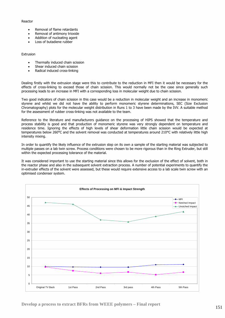
Develop a process to extract BFRs from WEEE polymers – Final report 151
Reactor
• Removal of flame retardants • Removal of antimony trioxide • Addition of nucleating agent • Loss of butadiene rubber
Extrusion
• Thermally induced chain scission • Shear induced chain scission • Radical induced cross-linking
Dealing firstly with the extrusion stage were this to contribute to the reduction in MFI then it would be necessary for the effects of cross-linking to exceed those of chain scission. This would normally not be the case since generally such processing leads to an increase in MFI with a corresponding loss in molecular weight due to chain scission. Two good indicators of chain scission in this case would be a reduction in molecular weight and an increase in monomeric styrene and whilst we did not have the ability to perform monomeric styrene determinations, SEC (Size Exclusion Chromatography) plots for the molecular weight distribution in Runs 1 to 3 have been made by the IVV. A suitable method for the assessment of rubber cross-linking was not available to the team. Reference to the literature and manufacturers guidance on the processing of HIPS showed that the temperature and process stability is good and that production of monomeric styrene was very strongly dependent on temperature and residence time. Ignoring the effects of high levels of shear deformation little chain scission would be expected at temperatures below 260°C and the solvent removal was conducted at temperatures around 210°C with relatively little high intensity mixing. In order to quantify the likely influence of the extrusion step on its own a sample of the starting material was subjected to multiple passes on a lab twin screw. Process conditions were chosen to be more rigorous than in the Ring Extruder, but still within the expected processing tolerance of the material. It was considered important to use the starting material since this allows for the exclusion of the effect of solvent, both in the reactor phase and also in the subsequent solvent extraction process. A number of potential experiments to quantify the in-extruder effects of the solvent were assessed, but these would require extensive access to a lab scale twin screw with an optimised condenser system.
Effects of Processing on MFI & Impact Strength
0
5
10
15
20
25
30
35
40
45
50
Original TV Back 1st Pass 2nd Pass 3rd pass 4th Pass 5th Pass
MFINotched ImpactUnotched Impact
Develop a process to extract BFRs from WEEE polymers – Final report 152
What can clearly be seen here is that the MFI was stable into the 5th extrusion pass and that the impact strength was also relatively stable after a noticeable reduction in the first extrusion pass. The option of repeating this work with additional anti-oxidant was considered, however the lack of change in MFI was seen as a strong indication that the underlying polymer structure was relatively stable during processing. Looking at the impact strength figures given the defect sensitivity of the material any changes their size and distribution would be expected to influence this. Therefore when comparing samples that had been extruded on a twin screw with the one that had only been injection moulded the drop in impact strength on the very first extrusion run was seen as less significant that the fact that the impact strength results did not show a downwards trend during the subsequent runs. Turning now to the in-reaction modifications of the starting material the primary object of the process is the removal of the brominated flame retardants and to a lesser extent the antimony trioxide synergist. The Size Exclusion Chromatography plot for the WT3 sample showed that the extraction process had removed a portion of the lower molecular weight material in the polymer peak. This resulted in an increase in the average molecular weight from 160,000 to 190,000 g/mol. This increase would be expected to reduce the MFI although it appears to be too small to account for it alone. A similar increase in molecular weight was observed for WT1 and to a lesser extend WT2. Interestingly the SEC plot was also monomodal, meaning that the SEC technique could not show differential changes in the polystyrene and rubber phases. Since there was however considerable concern that the polymeric material being removed was butadiene-based an IR analysis was performed on the residual slurry after precipitation. This showed only the presence of polystyrene. Both the brominated flame retardants and the antimony trioxide synergist are generally considered to be fillers, so their removal would be expected to result in an increase in MFI, however some of the flame retardants have melting points below the processing temperatures expected and have very low melt viscosities. Whilst the trend in brominated flame retardants is very much towards materials such a DecaBDE with melting points well above 300°C many of the older ones, which are also of most environmental concern, melt well below 200°C.
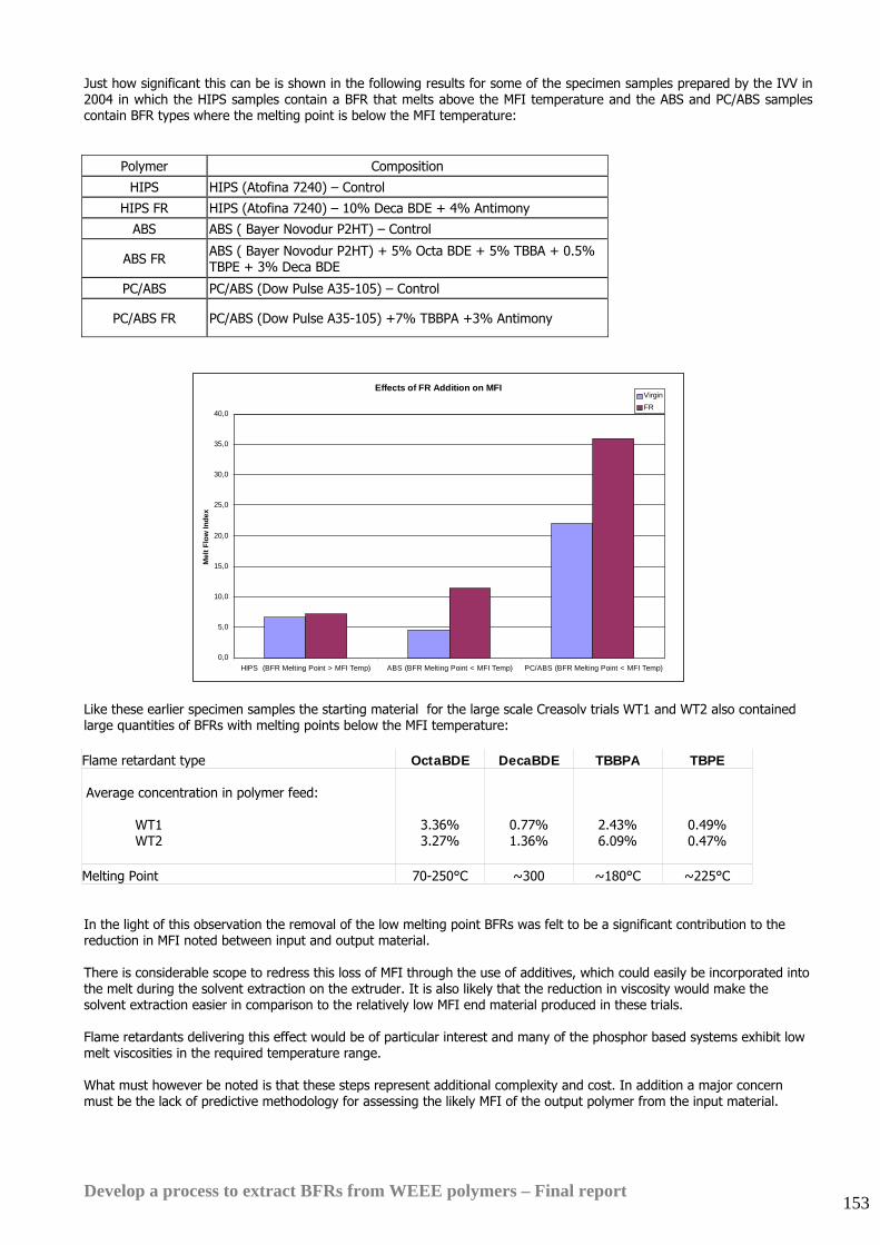
Develop a process to extract BFRs from WEEE polymers – Final report 153
Just how significant this can be is shown in the following results for some of the specimen samples prepared by the IVV in 2004 in which the HIPS samples contain a BFR that melts above the MFI temperature and the ABS and PC/ABS samples contain BFR types where the melting point is below the MFI temperature:
Polymer Composition
HIPS HIPS (Atofina 7240) – Control
HIPS FR HIPS (Atofina 7240) – 10% Deca BDE + 4% Antimony
ABS ABS ( Bayer Novodur P2HT) – Control
ABS FR ABS ( Bayer Novodur P2HT) + 5% Octa BDE + 5% TBBA + 0.5% TBPE + 3% Deca BDE
PC/ABS PC/ABS (Dow Pulse A35-105) – Control
PC/ABS FR PC/ABS (Dow Pulse A35-105) +7% TBBPA +3% Antimony
Like these earlier specimen samples the starting material for the large scale Creasolv trials WT1 and WT2 also contained large quantities of BFRs with melting points below the MFI temperature: Flame retardant type OctaBDE DecaBDE TBBPA TBPE Average concentration in polymer feed: WT1 WT2
3.36% 3.27%
0.77% 1.36%
2.43% 6.09%
0.49% 0.47%
Melting Point 70-250°C ~300 ~180°C ~225°C In the light of this observation the removal of the low melting point BFRs was felt to be a significant contribution to the reduction in MFI noted between input and output material. There is considerable scope to redress this loss of MFI through the use of additives, which could easily be incorporated into the melt during the solvent extraction on the extruder. It is also likely that the reduction in viscosity would make the solvent extraction easier in comparison to the relatively low MFI end material produced in these trials. Flame retardants delivering this effect would be of particular interest and many of the phosphor based systems exhibit low melt viscosities in the required temperature range. What must however be noted is that these steps represent additional complexity and cost. In addition a major concern must be the lack of predictive methodology for assessing the likely MFI of the output polymer from the input material.
Effects of FR Addition on MFI
0,0
5,0
10,0
15,0
20,0
25,0
30,0
35,0
40,0
HIPS (BFR Melting Point > MFI Temp) ABS (BFR Melting Point < MFI Temp) PC/ABS (BFR Melting Point < MFI Temp)
Mel
t Flo
w In
dex
VirginFR
Develop a process to extract BFRs from WEEE polymers – Final report 154
20.3. Discussion of Loss of Impact Strength Since HIPS is as its name suggests is used in applications where good impact strength is important any loss of impact strength during the recycling process is significant. During the progress of this project large improvements were made in final impact strength of the Creasolv product in comparison to the lab scale samples that were produced in Phase 2 of the project. As with the MFI results an attempt was made to assess the individual contributions of the reactor and extrusion stages: Reactor
• Loss of butadiene rubber • Loss of rubber domain structure • Removal of additives • Addition of nucleating agents
Extrusion
• Thermally induced chain scission • Shear induced chain scission • Radical induced cross-linking • Loss of rubber domain structure
In considering the possible causes it is important to pay regard to the fact that HIPS is not only a multi-component system, but also a micro-structured one. That means that changes in physical form can be just as significant as changes in chemical composition. The primary components of HIPS are polystyrene, polystyrene/butadiene graft copolymer and polybutadiene. Whilst polystyrene and polybutadiene are highly incompatible the complex mixture formed by co-reacting styrene and butadiene leads to a stable product with very finely dispersed rubber domains in the polystyrene/graft copolymer matrix. It is the interruption of crack propagation by these rubber domains that leads to the superior impact properties when compared to simple polystyrene. However this means that changes to the number, size and elasticity of these domains will affect the impact properties. Although the structures within HIPS are of a size that would be amenable to light microscopy the black colour of the sample meant that only SEM would be suitable for evaluating this and we would recommend that this form part of any further investigating and process optimisation. Parallel to this, multiple pass processing of the original TV backs also offered a good opportunity to look at the behaviour of the starting polymer under extrusion conditions in isolation to the effects of additive removal and solvent treatment. This work showed that whilst the original starting material had a notched impact strength of about 10 kJ/m2, this fell back to about 6 - 7 kJ/m2 after the initial extrusion run. When this material was then processed further with multiple extrusion runs the further passes through the extruder did not reduce notched impact strength greatly. In the light of this observation the value of 5 kJ/m2 for the finished Creasolv product could be expected given the prolonged extrusion necessary to remove the solvent in the pilot trials. Based on its observations of the pilot solvent removal trials Axion believes that a well-designed solvent removal extruder should be able to remove solvent down to the target concentration in only one or two passes. This should lead to reduced degradation of the impact strength.
Develop a process to extract BFRs from WEEE polymers – Final report 155
20.4. Effects of Residual Solvent At levels substantially above 1% a very large increase in MFI and decrease in HDT was noted. Interestingly notched Izod impact strength appears to be insensitive to solvent content over quite a wide range. However what also became apparent is that thermo-gravimetric analysis is not suitable for solvent contents near or below 1%, since, although on the basis of thermo-gravimetric testing the Centrevap samples were all thought to contain very low levels of solvent, they showed inappropriate MFIs and HDTs. Fraunhofer IVV compared its thermo-gravimetric solvent content results directly to ones measured using gas chromatography (GC) and found a significant underreporting:
Sample ppm Creasolv solvent measured by GC
%Total Solids measured by GC
%Total Solids measured thermo-
gravimetrically Creasolv large scale trial Ring Extruder Run 3
8810 99,1% 99,7%
Creasolv large scale trial Ring Extruder Run 4
5310 99,4% 99,9%
However it should also be noted that the specification for 1% or less of residual solvent held up well in terms of its limited influence on the major physical characteristics. What could not be assessed within the scope of the project was the effect of such levels of solvent on ageing properties.
20.5. Centrevap test results Samples from the large scale Centrevap process trials showed signs of plate-out during the tensile testing which may have been due to contamination with an incompatible polymer, but would also be consistent with some of the effects of elevated solvent levels noted by the IVV. As with the Creasolv process results the Centrevap product test results demonstrate that solvent content appears to have only limited effect on notched impact strength and solvent content. Notched impact strength is almost identical between samples that have a factor three difference in MFI due to residual solvent:
Sample MFI Notch Impact Strength Unnotched Impact Strength
HDT
Starting HIPS from TV casings
10 g/ 10min 9.7 kJ/m2 47 kJ/m2 -
AX 06 006 Centrevap Run3
46.7 g/10min 10.6 kJ/m2 43.6 kJ/m2 51°C
AX 06 006 Centrevap Run4
16.0 g/10min 10.8 kJ/m2 48.9 kJ/m2 69°C
AX 06 008 Centrevap Run4 + further solvent removal on Rondol twin screw extruder
16.4 g/10min
10.7 kJ/m2 60.6 kJ/m2 69°C
Typical commercial HIPS
3-15g/10min 5-12 kJ/m2 - 75-95°C
Overall, test results for the final large scale Centrevap samples show much better maintenance of material properties than for the Creasolv process. However it is important to remember that the Centrevap process did not remove the key BFRs.
Develop a process to extract BFRs from WEEE polymers – Final report 156
20.6. Summary of material testing results
• The final large scale Creasolv process sample has a notched impact strength of 5 kJ/m2. This is better than unmodified PS, but relatively low for HIPS
• The Creasolv extraction process raised the average molecular weight by between 6 and 18% (probably due to
removal of lower molecular weight polymer in the solvent extraction process)
• Removal of the low melting point BFRs was a significant contribution to the reduction in MFI.
• Impact strength was found to be relatively independent of solvent content • Thermo-gravimetric determination of solvent content is problematic • HDT is a good indicator of solvent content
• The Centrevap process option maintained the impact properties of the material well.
Develop a process to extract BFRs from WEEE polymers – Final report 157
21. Environmental impact assessment
21.1. Methodology Two separate environmental impact assessments were conducted for this project:
• ISO 14040 standard qualitative and quantitative environmental impact assessment using conventional impact assessment methodology by White Young Green Consulting, Leeds
• Quantitative ‘QWERTY’ eco-efficiency analysis by Huisman Recycling Research, University of Delft, Netherlands The White Young Green analysis may be compared directly with other environmental impact assessments prepared recently for WRAP. The Huisman QWERTY analysis is specifically designed to assess the eco-efficiency of WEEE recycling processes and has now been used several times in Europe to assess other treatment methods for WEEE including dismantling, mechanical recycling, incineration with energy recovery and treatment of whole WEEE items in non-ferrous metal smelters. Using the QWERTY technique to assess the processes developed in the course of this project will permit accurate quantitative comparisons with other WEEE treatment methods. The QWERTY analysis is not performed under classic life cycle analysis standards as specified in ISO14040 because:
• Unusual system boundaries are applied. Only the end of life phase is reviewed, not the full product life cycle • It is a sectoral approach rather than a classic product-oriented approach. It addresses the behaviour of individual
materials in a larger system, including distribution of different materials to various destinations based on Axion’s modelling of technology that does not yet fully exist.
• Some of the base technical and commercial data used in the analysis is confidential. Reporting under ISO14040 would require full disclosure
• Weighting of multiple input categories is applied in order to estimate a single indicator for comparison of disposal options. This is not in line with the stringent reporting requirements of ISO14040.
Details of the methodologies and assumptions used for each analysis are attached at Appendices 5A-5F. The full analyses were conducted for the short list of 6 possible processing or disposal options during phase 2 of the project. These results are detailed in Appendix 5. The results were updated in Phase 3 only for the Creasolv and Centrevap process options. The updates were conducted because further process design and large scale testing work during Phase 3 had made significant changes to the process capital costs and mass balances. Appendices 5E and F present the Phase 3 update reports The results and discussion in this section refer to the latest updated results.
Develop a process to extract BFRs from WEEE polymers – Final report 158
21.2. Qualitative comparison Initially White Young Green made a qualitative comparison of the potential environmental benefits and burdens of the disposal options considered in the course of this study. The full report is presented at Appendix 5A:
The qualitative assessment identified the Creasolv, mechanical recycling with BFR separation and Centrevap process options as combining the lowest environmental burden with the best environmental gain. Note that landfill disposal is deemed to have very low environmental impact (because it consumes only the energy required to transport the material to the landfill site and because the plastic does not degrade appreciably in the landfill. However landfill also creates no environmental gain because no material is recovered to substitute production of virgin polymer. The qualitative assessment included an evaluation of the potential environmental toxicology of the different process options. Detail of this assessment is included at Appendix 5.
Potential Environmental Benefit L H
H
Pote
ntia
l Env
ironm
enta
l Bur
den
Landfill
Mechanical Recycling (BFR plastics removed)
Feedstock
Ionic Liquids
Creasolv
Centrevap
Incineration
Incineration (with EfW)
Anti-solvent
Develop a process to extract BFRs from WEEE polymers – Final report 159
21.3. Quantitative comparison The quantitative analysis performed by White Young Green during Phase 2 of the project measured the environmental burdens and gains of the process options for three representative impact categories:
• Primary energy consumption (PE) • Global Warming potential (GWP) • Photochemical oxidation potential (POCP)
Detailed assumptions and analysis are presented in Appendix 5A, with the Phase 3 update report attached at Appendix 5F. The updated analysis for the Creasolv and Centrevap processes alone, which was conducted during Phase 3, did not change the overall conclusions of the Phase 2 analysis so the results are presented in detail at Appendix 5F and are not repeated here. The graphs below were prepared during Phase 2 of the project and compare the environmental impacts of all of the processes considered in detail during the project in each of the impact categories that were considered:
Comparison of Primary Energy consumption (MJ)
-140000
-120000
-100000
-80000
-60000
-40000
-20000
0
20000
40000
60000
80000
Creasolv
Ionic Liquids
Centrevap
Antisolvent
Mechanical R
ecycling with
BFR
sep.
Feedstock recycling
Landfill
Incineration (no EfW
)
Incineration (with E
fW)
MJ
Potential BurdenPotential BenefitNet Impact
Develop a process to extract BFRs from WEEE polymers – Final report 160
Comparison of scenarios for GWP
-1000
-800
-600
-400
-200
0
200
400
600
800
1000
1200
1400
1600
1800
2000
Creasolv
Ionic Liquids
Centrevap
Antisolvent
Mechanical R
ecyclingw
ith BFR
sep.
Feedstock recycling
Landfill
Incineration (no EfW
)
Incineration (with E
fW)
kg C
O2
equi
v.Potential BurdensPotential CreditsNet Impact
Comparisons of scenarios for POCP
-0.50
-0.40
-0.30
-0.20
-0.10
0.00
0.10
0.20
0.30
0.40
0.50
0.60
Creasolv
Ionic Liquids
Centrevap
Antisolvent
Mechanical R
ecyclingw
ith BFR
sep.
Feedstock recycling
Landfill
Incineration (no EfW
)
Incineration (with E
fW)
kg e
thyl
ene
equi
v.
Potential BurdensPotential CreditsNet Impact
Develop a process to extract BFRs from WEEE polymers – Final report 161
The quantitative comparison must be interpreted by comparing the relative impacts of each of the process options across each of the impact categories. In terms of primary energy consumption and global warming potential Creasolv, Centrevap and mechanical recycling with BFR separation appear to provide the best net environmental gain because they avoid the substantial environmental impact of production of a significant quantity of high grade polymer. In terms of primary energy consumption the environmental burden of these recovery processes (including transport of the materials from point of collection to point of treatment) is less than 20% of the burden of the virgin polymer production process, even when the yield of the recovery process is taken into account. Centrevap is estimated to be less attractive than Creasolv and mechanical recycling in terms of photochemical oxidation potential because it has potential for greater emissions of volatile solvents. Incineration with energy recovery does well in terms of primary energy consumption but looks less good in terms of global warming potential and photochemical oxidation potential. See Appendices 5A and 5F for White Young Green’s more comprehensive discussion of these results.
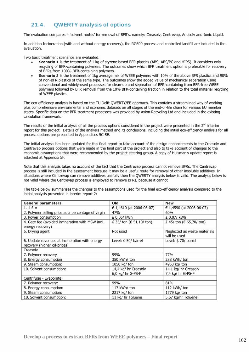
Develop a process to extract BFRs from WEEE polymers – Final report 162
21.4. QWERTY analysis of options The evaluation compares 4 ‘solvent routes’ for removal of BFR’s, namely: Creasolv, Centrevap, Antisolv and Ionic Liquid. In addition Incineration (with and without energy recovery), the RGS90 process and controlled landfill are included in the evaluation. Two basic treatment scenarios are evaluated:
• Scenario 1 is the treatment of 1 kg of styrene based BFR plastics (ABS; ABS/PC and HIPS). It considers only recycling of BFR-containing polymers. The outcomes show which BFR treatment option is preferable for recovery of BFRs from 100% BFR-containing polymers.
• Scenario 2 is the treatment of 1kg average mix of WEEE polymers with 10% of the above BFR plastics and 90% of non-BFR plastics of the same type. The outcomes show the added value of mechanical separation using conventional and widely-used processes for clean-up and separation of BFR-containing from BFR-free WEEE polymers followed by BFR removal from the 10% BFR-containing fraction in relation to the total material recycling of WEEE plastics.
The eco-efficiency analysis is based on the TU Delft QWERTY/EE approach. This contains a streamlined way of working plus comprehensive environmental and economic datasets on all stages of the end-of-life chain for various EU member states. Specific data on the BFR treatment processes was provided by Axion Recycling Ltd and included in the existing calculation framework. The results of the initial analysis of all the process options considered in the project were presented in the 2nd interim report for this project. Details of the analysis method and its conclusions, including the initial eco-efficiency analysis for all process options are presented in Appendices 5C-5E. The initial analysis has been updated for this final report to take account of the design enhancements to the Creasolv and Centrevap process options that were made in the final part of the project and also to take account of changes to the economic assumptions that were recommended by the project steering group. A copy of Huisman’s update report is attached at Appendix 5F. Note that this analysis takes no account of the fact that the Centrevap process cannot remove BFRs. The Centrevap process is still included in the assessment because it may be a useful route for removal of other insoluble additives. In situations where Centrevap can remove additives usefully then the QWERTY analysis below is valid. The analysis below is not valid where the Centrevap process is employed to remove BFRs, because it cannot The table below summarises the changes to the assumptions used for the final eco-efficiency analysis compared to the initial analysis presented in interim report 2: General parameters Old New 1. 1 ₤ = € 1,4610 (at 2006-06-07) € 1,4590 (at 2006-06-07) 2. Polymer selling price as a percentage of virgin 47% 60% 3. Power consumption ₤ 0,06/ kWh ₤ 0,07/ kWh 4. Gate fee (avoided incineration with MSW incl. energy recovery)
₤ 35/ ton (€ 51,10/ ton) ₤ 45/ ton (€ 65,70/ ton)
5. Drying agent Not used Neglected as waste materials will be used
6. Update revenues at incineration with energy recovery (higher oil-prices)
Level: $ 50/ barrel Level: $ 70/ barrel
Creasolv 7. Polymer recovery 99% 77% 8. Energy consumption 350 kWh/ ton 288 kWh/ ton 9. Steam consumption: 1050 kg/ ton 4953 kg/ ton 10. Solvent consumption: 14,4 kg/ hr Creasolv
6,0 kg/ hr G-PS-F 14,1 kg/ hr Creasolv 7,4 kg/ hr G-PS-F
Centrifuge - Evaporate 7. Polymer recovery: 99% 81% 8. Energy consumption: 117 kWh/ ton 112 kWh/ ton 9. Steam consumption: 2217 kg/ ton 1779 kg/ ton 10. Solvent consumption: 11 kg/ hr Toluene 5,67 kg/hr Toluene
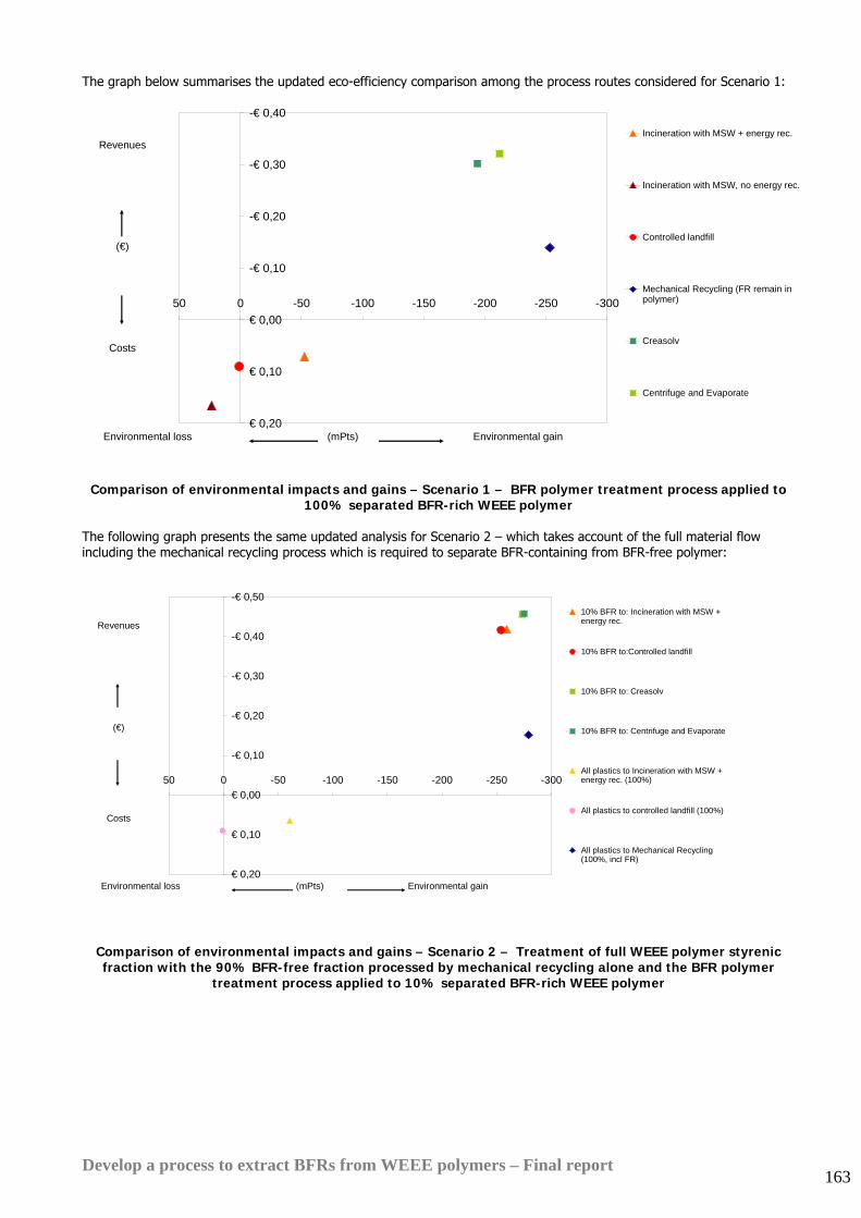
Develop a process to extract BFRs from WEEE polymers – Final report 163
The graph below summarises the updated eco-efficiency comparison among the process routes considered for Scenario 1:
-€ 0,40
-€ 0,30
-€ 0,20
-€ 0,10
€ 0,00
€ 0,10
€ 0,20
-300-250-200-150-100-50050
Incineration with MSW + energy rec.
Incineration with MSW, no energy rec.
Controlled landfill
Mechanical Recycling (FR remain inpolymer)
Creasolv
Centrifuge and Evaporate
Revenues
(€)
Costs
Environmental loss (mPts) Environmental gain
Comparison of environmental impacts and gains – Scenario 1 – BFR polymer treatment process applied to 100% separated BFR-rich WEEE polymer
The following graph presents the same updated analysis for Scenario 2 – which takes account of the full material flow including the mechanical recycling process which is required to separate BFR-containing from BFR-free polymer:
-€ 0,50
-€ 0,40
-€ 0,30
-€ 0,20
-€ 0,10
€ 0,00
€ 0,10
€ 0,20
-300-250-200-150-100-50050
10% BFR to: Incineration with MSW +energy rec.
10% BFR to:Controlled landfill
10% BFR to: Creasolv
10% BFR to: Centrifuge and Evaporate
All plastics to Incineration with MSW +energy rec. (100%)
All plastics to controlled landfill (100%)
All plastics to Mechanical Recycling(100%, incl FR)
Revenues
(€)
Costs
Environmental loss (mPts) Environmental gain
Comparison of environmental impacts and gains – Scenario 2 – Treatment of full WEEE polymer styrenic fraction with the 90% BFR-free fraction processed by mechanical recycling alone and the BFR polymer
treatment process applied to 10% separated BFR-rich WEEE polymer
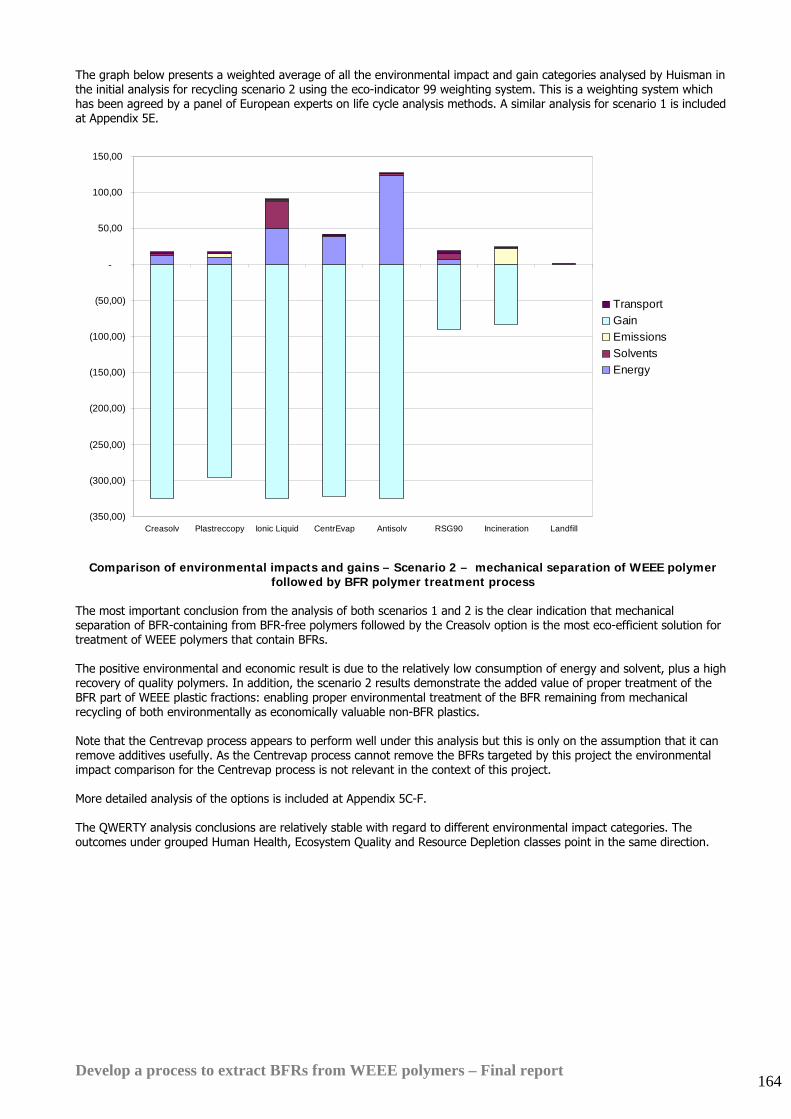
Develop a process to extract BFRs from WEEE polymers – Final report 164
The graph below presents a weighted average of all the environmental impact and gain categories analysed by Huisman in the initial analysis for recycling scenario 2 using the eco-indicator 99 weighting system. This is a weighting system which has been agreed by a panel of European experts on life cycle analysis methods. A similar analysis for scenario 1 is included at Appendix 5E.
(350,00)
(300,00)
(250,00)
(200,00)
(150,00)
(100,00)
(50,00)
-
50,00
100,00
150,00
Creasolv Plastreccopy Ionic Liquid CentrEvap Antisolv RSG90 Incineration Landfill
TransportGainEmissionsSolventsEnergy
Comparison of environmental impacts and gains – Scenario 2 – mechanical separation of WEEE polymer followed by BFR polymer treatment process
The most important conclusion from the analysis of both scenarios 1 and 2 is the clear indication that mechanical separation of BFR-containing from BFR-free polymers followed by the Creasolv option is the most eco-efficient solution for treatment of WEEE polymers that contain BFRs. The positive environmental and economic result is due to the relatively low consumption of energy and solvent, plus a high recovery of quality polymers. In addition, the scenario 2 results demonstrate the added value of proper treatment of the BFR part of WEEE plastic fractions: enabling proper environmental treatment of the BFR remaining from mechanical recycling of both environmentally as economically valuable non-BFR plastics. Note that the Centrevap process appears to perform well under this analysis but this is only on the assumption that it can remove additives usefully. As the Centrevap process cannot remove the BFRs targeted by this project the environmental impact comparison for the Centrevap process is not relevant in the context of this project. More detailed analysis of the options is included at Appendix 5C-F. The QWERTY analysis conclusions are relatively stable with regard to different environmental impact categories. The outcomes under grouped Human Health, Ecosystem Quality and Resource Depletion classes point in the same direction.
Develop a process to extract BFRs from WEEE polymers – Final report 165
21.5. Analysis All three assessment techniques (qualitative, conventional quantitative and QWERTY) conclude that, of the treatment solutions considered, the Creasolv process appears to be the best environmental option. Across almost all impact categories it has the best balance of environmental gain compared to environmental impact. Although Centrevap appears to perform well it should be ignored in the context of this WRAP project because it will not remove the types of BFR targeted by this project. Other points to conclude from the analysis:
• Landfilling BFR polymers has low environmental impact (at least in the short to medium term) but because no material is recovered it also has no environmental gain
• Incineration with energy recovery has a net environmental gain across almost all impact categories, although the gain is smaller than the gain from mechanical recycling or from the recovery processes tested in this project. It is certainly a more attractive option than landfill for polymers which are too dirty or commingled to be suitable for mechanical recycling
Disposal to non-ferrous metal smelting processes Another disposal option which was considered in Phase 1 of this project is use of BFR polymer as a feedstock for non-ferrous metal smelting processes. Previous technical trials and environmental impact analyses have identified that these processes can provide an efficient treatment route for WEEE items that contain a high proportion of metals and polymers additives. Advantages of these processes include:
• Low emissions due to the Bromine content present due to sophisticated flue gas cleaning and good prevention of dioxin emissions.
• Recovery of the lead and antimony content, cadmium is removed effectively as well. • A good environmental replacement by reducing coke consumption (coke is an environmentally burdening
material). Of special interest is the Umicore non-ferrous smelting process for materials containing both BFR's as well as precious and special metals85. Typical examples are printed circuit boards, mobile phone handsets or similar small electronic devices. For such materials a single process can take care of the BFR's while simultaneously recovering valuable metals. Hence an extra separation step for BFR plastics can be avoided, saving costs and optimising metals (particularly precious metals) recovery rates. Further analysis is required to assess whether the BFR plastics stream considered in this project is really suitable for the Umicore process both technically and economically as the metal content and value is relatively low. In the initial screening analysis it was concluded that these types of processes are most suited to direct treatment of undismantled small WEEE items such as mobile phones and MP3 players. It is difficult assess the crossover point where the cost of dismantling and polymer separation is outweighed by the material value of the polymer that is recovered. An option is to use processes such as the one operated by Umicore to treat the BFR-metal-inert fraction obtained in the solvent routes. The Br and metal content is substantial in this case and it would otherwise be landfilled unless the bromine industry can accept it as a feedstock. In this context a widened scope of the investigation including preceding steps in the recycling chain could be of interest. For the longer term, it is advised to further improve the reliability of the environmental impact estimates by:
• repeating the calculations for actual mass and energy balances of full scale operations • obtaining more accurate environmental impact inventories of the solvents consumed • examining the potential dioxin formation and release compared to alternative disposal methods such as
incineration and landfill and the effects of corresponding preventive measures • including VOC emissions at solvent recovery when applicable.
85 ‘Optimising the recycling chain – the contribution of an integrated metals smelter and refinery’, Hageluken, C., Umicore Precious Metals Refining, International Conference on Mining and the Environment, Metals and Energy Recovery, Skelleftea, June 2005.
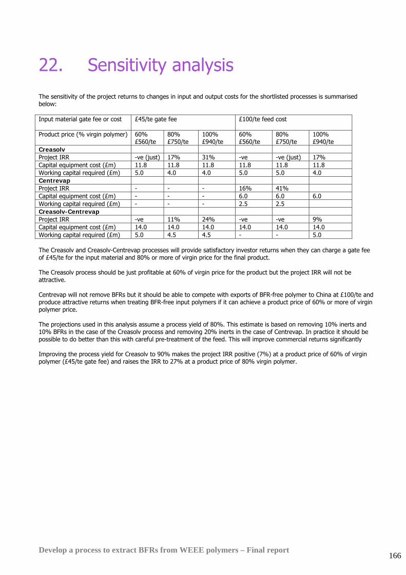
Develop a process to extract BFRs from WEEE polymers – Final report 166
22. Sensitivity analysis
The sensitivity of the project returns to changes in input and output costs for the shortlisted processes is summarised below: Input material gate fee or cost £45/te gate fee
£100/te feed cost
Product price (% virgin polymer) 60% £560/te
80% £750/te
100% £940/te
60% £560/te
80% £750/te
100% £940/te
Creasolv Project IRR -ve (just) 17% 31% -ve -ve (just) 17% Capital equipment cost (£m) 11.8 11.8 11.8 11.8 11.8 11.8 Working capital required (£m) 5.0 4.0 4.0 5.0 5.0 4.0 Centrevap Project IRR - - - 16% 41% Capital equipment cost (£m) - - - 6.0 6.0 6.0 Working capital required (£m) - - - 2.5 2.5 Creasolv-Centrevap Project IRR -ve 11% 24% -ve -ve 9% Capital equipment cost (£m) 14.0 14.0 14.0 14.0 14.0 14.0 Working capital required (£m) 5.0 4.5 4.5 - - 5.0 The Creasolv and Creasolv-Centrevap processes will provide satisfactory investor returns when they can charge a gate fee of £45/te for the input material and 80% or more of virgin price for the final product. The Creasolv process should be just profitable at 60% of virgin price for the product but the project IRR will not be attractive. Centrevap will not remove BFRs but it should be able to compete with exports of BFR-free polymer to China at £100/te and produce attractive returns when treating BFR-free input polymers if it can achieve a product price of 60% or more of virgin polymer price. The projections used in this analysis assume a process yield of 80%. This estimate is based on removing 10% inerts and 10% BFRs in the case of the Creasolv process and removing 20% inerts in the case of Centrevap. In practice it should be possible to do better than this with careful pre-treatment of the feed. This will improve commercial returns significantly Improving the process yield for Creasolv to 90% makes the project IRR positive (7%) at a product price of 60% of virgin polymer (£45/te gate fee) and raises the IRR to 27% at a product price of 80% virgin polymer.
Develop a process to extract BFRs from WEEE polymers – Final report 167
23. Conclusions and recommendations
Overall this project concludes that mechanical separation followed by a chemical process that removes brominated flame retardant additives from BFR-containing polymers is likely to be a better environmental and commercial option for treatment of WEEE plastics than landfill, incineration with energy recovery or feedstock recycling
Mechanical separation trials conducted during Phase 2 of the project demonstrated that:
• Identification of BFR-containing polymers by both BFR content and polymer type at WEEE dismantling facilities is technically feasible using relatively low cost, fast-acting hand-held instruments.
• Separation of polymers by type at dismantling facilities adds greatly to polymer value and should be commercially viable for WEEE items over about 0.5Kg weight, providing the UK authorities enforce the requirements of Annex 2 of the WEEE Directive regarding separate treatment of hazardous materials prior to shredding.
• Bulk separation of a clean mixed styrenic polymer fraction from mixed WEEE polymer by density is technically feasible and should be commercially viable in the UK.
• X-ray based polymer chip sorting is extremely promising as a commercially viable technique for bulk separation of polymers containing bromine, and other elements such as chlorine, lead and cadmium.
The more detailed and larger scale test work conducted during Phase 3 of this project has confirmed that the Creasolv process can remove all BFR types commonly found in WEEE polymers close to the 0.1% target set for this project.
The test work in Phase 3 has demonstrated that the Centrevap process option will not be able to achieve the BFR removal target set for this project. It can only remove impurities and polymer additives which are insoluble in the types of solvent required to dissolve the polymer.
However in other respects Centrevap is the most commercially viable solvent-based recycling process that has been tested in the course of this project. It is a flexible, easy to control and robust process design which is capable of removing insoluble polymer impurities and additives down to micron scale with a very short process residence time.
Business modelling indicates that both the Creasolv and Centrevap process options should be capable of operating at a profit and competitive with landfill or incineration under current UK economic conditions at a throughput of 10,000te/yr and with a recyclate price of 60% of virgin polymer. However Creasolv is only marginally profitable and the overall project IRR is projected to be negative at this product price.
If demand for high grade recyclate grows and the recyclate price increases to 80% of virgin polymer then the financial models created for this project indicate that both process options will be attractive investment propositions, provided the Creasolv option can attract a gate fee for segregated BFR-containing input material of about £45/te.
The Creasolv process option will generate attractive returns and be able to pay a positive price of £100/te for its input material to compete with exports to China if it can achieve a sales price of 80-90% of virgin polymer. Recent market research by Axion indicates that end users are increasingly prepared to pay prices in this range for top grade recyclates
Both the Creasolv and Centrevap process options should be considered in the context of the overall waste management picture for WEEE. Neither process is appropriate for treating all WEEE polymer types.
Creasolv will remove most BFRs efficiently from most styrenic polymers found in WEEE. It will not remove antimony trioxide.
Centrevap will remove very small insoluble impurities, including fillers and antimony trioxide, from styrenic and other solvent-soluble polymers but it will not remove BFRs because most BFR types are partially soluble in the solvents used in this project.
Both process options require sorting or mechanical separation of WEEE polymers by type before treatment. However, with further process development, both processes offer the potential to produce very high grade recyclates, suitable for immediate re-use in new electrical and electronic equipment.
Combining the best features of the Centrevap and Creasolv processes has potential to produce a process which can remove not only the majority of BFRs but also the majority of other fine particulate contaminants, such as antimony trioxide, that are not soluble in the Creasolv solvents. However the capital cost of this option is higher.
WRAP and Fraunhofer IVV have entered into a technology sharing agreement which will make the Creasolv process technology available for license in the UK via WRAP.
Axion Recycling November 2006 www.axionrecycling.com
Appendix 1 – Developments in EU and UK legislation applying to polymers containing BFRs
Outcomes of the third UK consultation on the WEEE Directive The UK Government’s third UK Consultation on the WEEE Directive discussed issues concerning :-
• transposing the Directives in Autumn 2004 • registration of producers and data reporting from producers from start of 2005, especially sales data for 2004 in
order to calculate market share • establishing a National Clearing House
The Environment Agency also consulted on draft guidance for the treatment and storage of WEEE at treatment facilities1. The draft guidance included the following proposed requirements:
• removal of fluids and certain substances • systems for treatment must use Best Available Treatment Recovery and Recycling Techniques (BATRRT), which
will be further defined in guidance from Defra. • treatments must ensure compliance with Article 4 of the Waste Framework Directive (75/442/EEC) – waste is
recovered or disposed of without endangering human health or the environment. Also, the Council Regulation No. 2037/2000 (as amended) on Ozone Depleting Substances, Council Directive on hazardous waste (91/689/EEC) and possibly the European Waste Catalogue distinction between hazardous and non-hazardous entries.
• treatment processes must comply with The Management of Health & Safety at Work Regulations 1999, The Control of Substances Hazardous to Health Regulations 1999 (COSHH) and The Manual Handling Regulations 1992.
• treatment operations will require a permit (unless an exemption has been provided)
An EA/SEPA Consultation Draft on Guidance on Treatment of WEEE was also published in July 2004. Requirements in this draft guidance include:-
• treatment operations to be conducted at an authorised treatment facility (ATF) with a permit • Annex III of the Directive covers criteria concerning sites for storage, sites for treatment. This includes acceptable
and unacceptable criteria • site operators will have a data reporting requirement • priority to be given to re-use of whole appliances and then components, sub-assemblies and consumables • all separately collected WEEE that is not designated for re-use as whole appliances must be sent for treatment • systems for treatment of WEEE must use Best Available Treatment Recovery and Recycling Techniques (BATRRT)
– to be further defined via an amendment to the Waste Management Licensing Regulations 1994, with Consultation in September 2004
• treatments must ensure compliance with Article 4 of the Directive ; waste is recovered or disposed of without endangering human health and the environment
• treatment must avoid the dispersion of pollutants into the recycled material or the waste stream • fluids must be removed prior to crushing or shredding • The following specific items to be removed :-
o capacitors containing polychlorinated biphenyls (PCBs) o switches or lamps containing mercury o batteries o liquid and paste (balk and colour) from toner cartridges o plastic containing brominated flame retardents o asbestos o cathode Ray Tubes (CRTs) and also the fluorescent coating in the CRT
1 www.environment-agency.gov.uk/yourenv/consultations/830820/
o CFCs, HCFc, HFCs and HCs from refrigeration and cooling systems o gas discharge lamps + mercury o Liquid Crystal Displays (LCDs) if they have a surface area greater than 100 square centimetres or back-
lighted with a gas discharge lamp (this may be amended by the European Commission) o external electric cables o components containing refractory ceramic fibres o components containing radioactive substances o electrolyte capacitors
• The recycling target for modern mobile phones can be achieved by recycling the battery. • Requirements for removal of printed circuit boards are under priority review
Following the consultation process concerns were raised about several practical issues and also the legality of the Clearing House concept in EU law.
In February 2005 the Government announced that proposals for a National Clearing House needed simplifying.
In March 2005 several Local Authorities expressed concern that WEEE proposals might be put back to 2006, especially in terms of funding any upgrades to civic amenity sites.
They were also concerned about lack of investment in ‘new technologies’ to re-manufacture and/or recycle and/or recover WEEE.
In March 2005 DTI confirmed that :-
• new WEEE regulations would be completed later in 2005 • implementation of producer responsibility would be put back, to start on 26th January 2006 • the WEEE Directive would be transposed into UK law in summer 2005, accompanied by non-statutory guidance • producers would have to mark equipment to show it was put on the market after 13th August 2005 • a National Clearing House would not be established, because of “the complexities and public accountability
implications” • allocation of WEEE to producers will probably involve “… a mix of physical allocation (WEEE collection sites) to
larger producers and compliance schemes with a settlement mechanism enabling financial compliance by producers with smaller market share-based obligations”
• DTI still had some concern that any compliance scheme would be dominated by large producers, who will collect up all of the WEEE and then hold smaller manufacturers to ransom
• a Consultation Paper would be issued on draft regulations, and DTI, Defra and the Environment Agency would work with Local Authorities to clarify issues surrounding the July 2005 Waste Acceptance Criteria, which adjust the categorisation of hazardous wastes
• producers will be expected to make ’reasonable estimates, capable of corroboration’ of the number of units put onto the market during 2004, and the allocation to households or businesses
• producers reported weights of household equipment put on the market wouldbe used to calculate their obligations relating to household WEE arisings in the UK (not confirmed as yet whether this will be for all WEEE or the four WEEE groupings, especially as nearly 50% of household WEEE are small items normally put in the dustbin)
• producers would register with the Environment Agency, rather than the National Clearing House or DTI • the role of civic amenity sites as Designated Collection Points should be agreed by April/May 2005, with the British
Retail Consortium (BRC) funding a retail compliance scheme, including finance to upgrade civic amenity sites. Issues of take-back and reuse have still to be finalised. BRC estimate that current proposals could cost as much as £750 million
• DTI would follow a voluntary approach to the operation of visible fees covering the cost of recycling equipment, and will broker discussions between producers and retailers on how the system could operate
The revisions were welcomed by businesses, with some wanting the start delayed until after the busy Christmas period, preferably in April 2006.
In October 2005 industry proposed the concept of an arms-length ‘national settlement centre’ to help with producer responsibility for WEEE. Producers or compliance schemes could collect any amount of WEEE arising at a collection point regardless of their actual obligation, with compensation for any excess or payment for under-achieving being managed through such a centre, based on average costs for collected tonnages. As at November 2005 DTI was proposing a similar ‘allocation systems’ with larger companies collecting WEEE from designated collection facilities and passing some costs to smaller companies, perhaps using a free market system for evidence of compliance – similar to PRNs.
Experts claim that just over 1,000 sites will be needed to receive WEEE waste, and with 1,072 civic amenity sites the option of upgrading these sites to accept WEEE has been the favoured option of the retailers. However, several Local Authorities have been quoted between £500,000 and £1 million for upgrade to single sites : some are too small, five separate
containers are required and also additional staff. In addition, Local Authorities argue that they do not have targets for WEEE and the obligation (and costs) must rest with producers and retailers.
In May 2005 BRC established a fund for retailers to contribute into, and for payments to Local Authorities. The fund will be for £8.2 million over three years, with one-off payments of £5-6,000 to upgrade civic amenity sites. These amounts contrast with earlier estimates of contributing £5 million per annum over five years. The fund will also be used to support public education and special events to further enhance and improve the collection of WEEE. LARAC was “incredibly disappointed” at the amount of funding being offered, and many Local Authorities may not wish to participate.
In August 2005 LARAC argued that Local Authorities were being forced to register their civic amenity sites as Designated Collection Facilities (DCFs), so that retailers can claim an adequate collection network has been established. LARAC has written to Defra with various proposals : no site would be refused registration as a DCF, sites could sign up any time to be a DCF, signing-up would be for specific time periods, for sites designated as DCFs retailers and producers would control the specification of the sites and effectively controlling the costs involved.
Defra stated in October 2005 that it will leave consumers to police the legal requirements for small retailers to provide free take-back for WEEE after June 2006 – if they have not joined a compliance scheme and if they fail to take back WEEE or inform the consumer of a nearby collection point. This may involve c. 9,000 retailers, with less than 1% of retailer obligations. In contrast to packaging there are no threshold values for quantities of WEEE.
The Department of Trade and Industry announced on 10th August 2005 that manufacturers and retailers will now be responsible for the collection and recycling of WEEE from June 2006 rather than January 2006. According to the DTI, the postponement of six months has been made in the light of preparations needed for the European-set legislation. One of the main reasons for the delay is also to allow the retailers, led by the British Retail Consortium, to establish an adequate network of facilities for separate collection of WEEE for householders to use.
In the light of this announcement, the DTI said it will cover "new burden" costs incurred by Local Authorities for separately collecting electronic waste that has been newly classed as "hazardous" since changes to landfill regulations came into force in July 2005. One issue still to be clarified is that of Ozone Depleting Substances associated with fridges. The European Commissioner announced in November 2005 that all liquid and gaseous hydrocarbons must be removed from refrigeration equipment, including cooling circuits and insulation before further treatment and/or safe disposal.
A survey by letsrecycle in August 2005 indicated that the price for recycling a single CRT is between £3.50 and £7, with the debate focussing on whether to charge per unit or per tonne. Some companies (e.g. Sims Group) offer both, with transport costs being the main variable in charging and size also influencing the charge made by some companies.
Alongside BRC proposals, REPIC announced that they would provide Local Authorities with civic amenity sites allocated to them as designated collection facilities free collections and collection containers. Where sites are too small five separate “piles” of WEEE could be collected on a ”round robin” basis. The five containers would be for:
• Cooling appliances : fridges, freezers • other large domestic appliances : cookers, dishwashers, washing machines • cathode ray tubes : televisions and monitors • small domestic and mixed appliances : tools, hairdryers • lighting : fluorescent tubes, energy saving light bulbs
In July 2005 the European Commission formally asked eight Member States (Estonia, Finland, France, Greece, Italy, Malta, Poland and the UK) to transpose into their national laws three EU Directives tackling the environmental problems caused by the growing amount of electronic and electrical waste. This should have been done by 13 August 2004. If a Member State fails to comply with this request, the Commission could take it to the European Court of Justice.
The Directives in question aim to ensure that e-waste, which often contains hazardous materials, is not simply thrown away, but is collected, recycled and reused, with the remaining waste being properly treated. The actions are part of a series of environment-related infringement decisions against several Member States which the Commission is currently announcing. Environment Commissioner Stavros Dimas said: “Nobody wants to see old computers and television sets piling up at the roadside and polluting the environment. Therefore efficient collection and recycling/reuse is necessary. Member States have agreed on ambitious legislation to tackle the problems caused by rapidly growing amounts of E-waste. But they also have to do the follow-up work and implement what they have agreed.”
EU legislation on electrical and electronic waste : In 2002, the Council and European Parliament adopted the Directive on Waste Electrical and Electronic Equipment (WEEE Directive). This Directive requires Member States to ensure the establishment of systems for the collection of e-waste (by August 2005). Furthermore, they have to ensure its reuse, recovery and recycling, and the sound disposal of the remaining waste. When the collection systems are in place, consumers will be able to take these products back to shops and collection points for free. The Directive also sets collection, re-use and recycling targets and outlines the financial obligations of producers. A 2003 amendment to the WEEE Directive further clarifies those obligations with regard to the financing of professional (i.e. non-household) equipment.
Each EU citizen currently produces around 17-20 kg of e-waste per year. Some 90% of this waste is still landfilled, incinerated, or recovered without any pre-treatment. This allows the substances it contains to make their way into soil, water and air where they pose a risk to human health. The transposition of all three Directives was due before 13 August 2004. France, Italy and the United Kingdom have failed to transpose all three Directives. Finland has not yet transposed the three Directives in the province of Aland. Greece has transposed the earlier WEEE and RoHS Directives, but not the amendment to the WEEE Directive. Estonia, Malta and Poland have transposed the RoHS Directive but not yet the WEEE Directive and its amendment. The Commission has therefore sent final written warnings - the last step before referral to the European Court of Justice - to the eight Member States.
An interim report published by ICER in March 2005 (funded by Biffaward) suggests that the amount of WEEE thrown away by households is twice the figure previously thought – amounting to 1 million tonnes, or 16 kg per person. Other comments from the report :-
• many items are less than 2 kg and are thrown in the dustbin with other household waste • over two-thirds of the tonnage thrown away by household come from just 3 out of the ten categories : 78% =
large household appliances (washing machines, fridges, cookers), 13% = consumer equipment (mostly TVs), 8% = small household equipment, 7% = IT/telecomms, 4% = tools, lighting, toys, etc
• WEEE Directive focuses recovery and re-use producer obligations on separately collected WEEE • producer obligations (50,000 in UK ) are calculated on the basis of market share • costs of treating and recycling estimated to be up to £83 million, including £27 million for TVs and monitors
containing cathode ray tubes (CRTs) • costs for treatment and recycling of household WEEE : £5 per fridge, £7 per CRT, 30-40 pence for lighting. This
compares with most other WEEE at £100-200 per tonne
Progress on the implementation of the Waste Electrical and Electronic Equipment Directive (known as WEEE) is to be reviewed immediately, Energy Minister, Malcolm Wicks said 15th December 2005.
The WEEE Directive requires producers to pay for treatment and recycling or recovery of all WEEE products. Retailers have an obligation to offer take-back services to householders and will be providing a network of collection facilities where consumers can take back their WEEE for it to be collected separately from other municipal waste.
In announcing the review, Malcolm Wicks said: "This Government is firmly committed to sustainable development and recognises that effective implementation of the WEEE directive has a key role to play in achieving this goal. The Directive is challenging and effective implementation of its obligations requires a lot of planning and preparation - it is vital that the producers, retailers and the waste industry together with Government have the appropriate plans, infrastructure and regulations in place. We have listened to the concerns expressed by both the business community and other stakeholders over the implementation process and have decided that more time is needed to get the implementation right. Although any further delay is regrettable, this will ultimately deliver far greater environmental benefits. My officials will be working closely with colleagues from Defra and the Environment Agency which will form the basis for a formal consultation on draft regulations and guidance in the Spring."
“The Government recognises that this has implications for the burdens placed on Local Authorities to dispose of separately collected WEEE. We announced previously that DTI would meet Local Authority New Burdens costs in the light of Ministerial decisions to defer the WEEE implementation. Specifically, we have said that DTI will meet any costs to Local Authorities of arranging the treatments required for any televisions and PC monitors containing cathode ray tubes and fluorescent lamps which they collect separately (rendering these "hazardous") and sent to a hazardous waste landfill, in advance of the WEEE Regulations introducing producer responsibility for these costs, i.e. where local authorities have chosen to collect separately these categories of WEEE in the absence of any legislative requirement at this stage.”
“We have already agreed with Local Authorities that payment for costs incurred in 2005/06 will be included in the annual settlement figure for 2006/07. We will continue to work with Local Authorities to establish the costs associated with the decision to undertake this review.”
Additional regulations - WEEE Permitting regulations - are to be made by Defra, together with guidance on treatment operations. The Regulations will come into force alongside the producer responsibility requirements of the DTI WEEE regulations and will introduce the treatment permitting requirements of the WEEE Directive.
Government awarded Local Authorities £14.7 million to cover the cost of collecting hazardous WEEE from August 2005 – 1st June 2006.
28th March 2006 DTI published its Conclusions of Implementation Review + Implementation Proposals. A formal consultation will follow in ‘Spring’ 2006.
• strong support for producer and retailer responsibility. • approved compliance schemes for retailers, to establish Designated Collection Facilities (DCFs) – majority in
existing civic amenity sites and/or transfer stations. SMEs to be involved in compliance schemes, with
proportionate membership fees. A subsequent paper will cover approval criteria for compliance schemes. Or, retailers may take WEEE from households when selling new EEE
• obligatory registration for producers with EA – direct or via a (single) compliance scheme. Approval criteria for compliance schemes will be set out in a subsequent paper. Producer compliance schemes will negotiate with Local Authorities to collect sufficient WEEE
• a system for calculating producers’ obligations, based on calendar years and including weight of EEE placed on the market in the preceding year. Quarterly reports to be published by EA
• a quasi-market mechanism for allocation WEEE from DCFs – a fall-back system if sites are not cleared, with Local Authorities able to recover costs from the ‘central exchange’ system (WEEE-RNs similar to PRNs ?)
• a code of practice covering the collection of WEEE from DCFs • a network of Authorised Treatment Facilities, which will process WEEE and provide evidence to producers • protocols to enable producers to demonstrate achievement of recycling targets in a cost effective way • a voluntary approach for producers to show the cost of handling historical (‘orphan’) WEEE, with freedom through
supply chain negotiations on how to display the costs involved • role of voluntary groups in re-use of WEEE to be maximised
Following the release of the Conclusions of the Implementation Review paper on 27th March 2006, the DTi issued a further Supplementary Paper in May 2006, taking into account views expressed by stakeholders during the initial consultation period
The key changes made to the proposal issued in March 2006 are:
• a proposal to calculate producer obligations through five categories of WEEE rather than total tonnage : large household WEEE containing ozone-depleting substances, large household WEEE not containing ozone-depleting substances, televisions and monitors, fluorescent tubes, all other WEEE
• the term ‘retail compliance scheme’ to be replaced by ‘Distributor Deposit Scheme’ (to avoid confusion with producer compliance schemes)
• empowering the Secretary of State to appoint a distributor deposit scheme operator rather than approving applications and the intention to make an early appointment
• safeguards to discourage a producer compliance scheme from handling levels of WEEE greatly exceeding their member’s obligations, with a limit of over-collection of 5% of the market
• a more detailed policy approach to ‘business to business’ implementation. Producers will only be responsible for such WEEE if the items were purchased after 13th August 2005, otherwise producers will only be responsible for collecting WEEE if it is being replaced on a like-for-like basis. Business end users are likely to have their responsibilities confirmed within waste Duty of Care regulations, with Defra issuing a coinsultation shortly
• further clarification on the role of collection facilities, with the DCF network roughly equivalent to the number of existing civic amenity sites and a code of practice is being drawn up. DTI recognises the ‘disquiet’ over proposals to allocate £6,000 for each DCF as being ‘an unrealistic figure in relation to the real costs on the ground’.
• producer compliance schemes • the form of evidence used for collection and recycling from authorised treatment facilities will be evidence notes to
producer compliance schemes regarding the recycling of WEEE collected from DCFs. A central exchange will be established to purchase evidence notes (at cost) from producers and refunding Local Authorities as appropriate
The Implementation Team requested further comments from stakeholders on the Conclusions to the Implementation Review and the Supplementary Paper, especially with regard on the following issues:
• are the proposals workable? • if not, which elements need further consideration? • what additional factors need to be considered in order for the proposals to work effectively? • are there any loopholes that have been overlooked? • are there any contradictions between the various parts of the process?
Comments had to be submitted to,the DTI before 19 May 2006, in preparation for a full consultation in Summer 2006.
Of more general relevance, proposed new Hazardous Waste Regulations were published by Defra in August 2004, and were implemented in 2005. The 1996 Special Waste Regulations were intended to transpose the Hazardous Waste Directive (91/689/EEC) and the EC Hazardous Waste List (94/904/EC). On 1st January 2002 changes to the Hazardous Waste List were applied in the EU and the list was incorporated into the European Waste Catalogue (01/573/EC amending 00/532/EC and replacing 94/3/EC). In addition to replacing the term ‘special waste ’ with ‘hazardous waste’, the new regulations:
• mean that more waste items from businesses will be classed as hazardous waste, e.g. batteries, used oil, fluorescent tubes and computer monitors.
• where hazardous waste is mixed with non-hazardous waste, the whole skip becomes hazardous waste unless or until the hazardous component(s) are separated from the non-hazardous waste.
• make businesses who produce waste more aware of the waste they are producing through a requirement to notify (register with the Environment Agency). Waste carriers will not collect from unregistered producers. This will help to improve the ‘cradle to grave’ audit control of hazardous waste as required by the Directive
• encourage reduction in the amount of hazardous waste being produced by industry and businesses • reduce the current administrative burden
These new regulations exclude domestic waste rather than household waste : the former being from accommodation used purely for living purposes (and without commercial gain), whilst the latter includes premises such as church halls, residential homes, camp sites, prisons and building used for public meetings and by charities. Reference to Authorised Treatment Facilities is also relevant in the context of end-of-life vehicles (ELVs), and the requirement to de-pollute such vehicles prior to any recovery operations. Traditionally, end-of-life vehicles and various categories of WEEE have been handled through metal scrapyards with items being shredded to facilitate metal separation. Some of these sites operate to very high standards of environmental protection, some have full waste management licenses, some are exempt and some do not meet the standards set in the ELV Regulations 2003. A year-long amnesty ended on 31st October 2004, and during a campaign in Yorkshire in October 2004 the Environment Agency found that of 170 sites visited, 130 did not comply with their licences and a further 23 were operating illegally. At a global level, the Stockholm Convention met in Tokyo in October 2004 to consider classifying vehicle shredding as a major source of persistent organic pollutants. If accepted by the United Nations summit in Uruguay in May 2005, this would give the UK two years to phase out their use. One problem from such operations is the residual waste, usually referred to as Automotive Shredder Residue (ASR). Problems occurred in July 2004 with some landfill sites refusing to accept such material as it was considered to be hazardous waste, and new regulations (with effect from 16th July 2004) meant that co-disposal of hazardous and non-hazardous wastes was no longer possible. Some shredder companies were considering not accepting any ELVs for shredding. Following various meetings, the Environment Agency agreed to class this residue as non-hazardous under certain conditions, where shredders can demonstrate that their waste residues are non-hazardous through approved and suitable tests :-
• either because the waste residues arise from vehicles which have been de-polluted and hazardous materials removed in accordance with the DTI/Defra de-pollution guidance, and demonstrated in a waste transfer note when passing the reside to landfill operators. To apply with effect from 1st November 2004, subsequently extended to 1st December 2004.
• the waste residues are from other inputs which do not contain hazardous materials • a three-month window (initially until 1st November 2004, and then extended to 30th November 2004) was agreed
during which a simplified de-pollution checklist can apply where companies have yet to develop the capability to comply with the ELV Regulations 2003 : vehicle shredder waste will be classed as non-hazardous if it does not contain lead acid batteries, components identified as containing mercury (e.g. switches), engine oils and oil filters and fuel
• after 1st December 2004 all ELVs will have to fully de-polluted to the government set standards as set out in the ELV Regulations 2003. If not, ASR will have to be sent to a hazardous-only landfill site or authorised incinerator
In March 2006 the European Commission announced a period of consultation over possible exemptions of an annex to Directive 2002/95/EC of the European Parliament and of the Council on the restriction of the use of certain hazardous substances (ROHS) in electrical and electronic equipment. Article 4(1) of Directive 2002/95/EC on the restriction of the use of certain hazardous substances in electrical and electronic equipment (1) provides 'that from 1 July 2006, new electrical and electronic equipment put on the market does not contain lead, mercury, cadmium, hexavalent chromium, PBB or PBDE.' The annex to the Directive lists a limited number of applications of lead, mercury, cadmium and hexavalent chromium, which are exempted from the requirements of Article 4(1).
According to Article 5 (2) of Directive 2002/95/EC the Commission is required to consult the relevant stakeholders before amending the annex. The results of this consultation will be forwarded to the Technical Adaptation Committee of the Directive 2002/95/EC and the Commission services will provide an account of the information received. Although the Commission will analyse the results of this stakeholder consultation carefully, please note that as with all stakeholder consultations, this action is only one part of the decision making process. Proposal for additional exemptions Article 5(1)(b) of Directive 2002/95/EC provides that materials and components can be exempted from the substance restrictions contained in Article 4(1) if their elimination or substitution via design changes or materials and components which do not require any of the materials or substances referred to therein is technically or scientifically impracticable, or where the negative environmental, health and/or consumer safety impacts caused by substitution outweigh the environmental, health and/or consumer safety benefits thereof. On the basis of this provision the Commission has received from industry additional requests for applications to be exempted from the requirements of the RoHS Directive. The titles for the exemptions as submitted by industry and the request for exemptions are: 1. Cadmium and cadmium oxide in thick film pastes used on beryllium oxide substrates until January 1, 2008; 2. Gaskets of butyl rubber material vulcanised with chinondioxim and lead tetraoxide, for use in Aluminium Electrolytic Capacitors; 3. Sharp LQ104X2LX11 (formerly Fujitsu FLC26XGC6R-01); 4. Quartz Crystal Resonator and in Fine Pitch Electronics Systems used in the Swiss Watch Industry; 5. Cadmium in opto- electronic components; 6. Transducers used in professional loudspeaker systems, using tin-lead solder; 7. Tin-lead solder in the manufacture of professional audio equipment; 8. Components used in the manufacture of the Hog1000, Hog500, Event416, Event408, ESP2-24 and ESP2-48 lighting control consoles; 9. Specific modular units, including tin-lead solder, being used in special professional equipment; 10. Inventory of special ICS having tin-lead solder on/in leads/balls, used in specialist/professional equipment; 11. Cadmium Mercury Telluride; 12. Lead contained in Babbit lined bearings; 13. Cadmium alloys as electrical/mechanical solder joints to electrical conductors located directly on the voice coil in transducers used in high-powered loudspeakers; 14. Thermal cutoff with a fusible element that contains lead (and possibly cadmium, mercury and hexavalent chromium) for applications where normal operating temperature exceeds 140 C and reliable, predictable, operation for a minimum of 30,000 hours is required; 15. Mercury free flat panel lamp; 16. Electronic equipment where the reliability, durability and longevity of the equipment is paramount; 17. Semi Red Brass C84400, 81-3-7-9 or a similar Brass material. Used on radio frequency line sections; 18. Lead is used as an alloy to the copper in 6 to 8 % by weight. Needed for casting and machinability characteristics; 19. Lead in solders for electronic equipments used for the monitoring, the protection and the safety of people in healthcare, telecare and emergency calls domains in professional and private sectors; 20. FPGA devices manufactured by Xilinx (XC5202-6VQ100C, XC4003E-3VQ100C and XC4013E-3PQ240C) containing lead solder (Pb) used in the plating of the device terminations; 21. Lead oxide in seal frit used for making window assemblies for argon and krypton laser tubes; 22. Smart card readers (product: GemSelf700-MS2, GCR700-3ZS, Vodafone D2 , GCR760 and GemSelf750 SV); 23. Use of mercury in Babcock's DC plasma displays and use of Lead Oxide (PbO) in Babcock's DC plasma displays frit seal.

The Commission' Environment Directorate invited interested parties to send their comments by 15 May 2006 at the latest by e-mail to [email protected] or by post to: European Commission, DG Environnent, Unit G4 - Consultation Directive 2002/95/EC, B-1049, Brussels, Belgium.2
2 http://europa.eu.int/comm/environment/waste/rohs_5_consult.htm
Developments regarding WEEE recycling in the UK since January 2004 This is an attempt to provide a chronological review of developments and initiatives relating to practical implementation of WEEE recycling in the UK. European Recycling Platform (ERP)
• Sony, Braun, Electrolux and Hewlett Packard as founder members = established in November 2002 = 14% share of European electrical goods market.
• Contributed to a UK Centre for Economic and Environmental Development (UK CEED) research project into WEEE collection and treatment
• Wants to promote cost-efficient and innovative recycling strategies by embracing individual producer responsibility, thereby allowing waste disposal and management costs to become core business drivers. Developing and operating a common waste management procurement platform designed to meet the specific requirements of EEE producers
• Not keen on visible fees In November 2004 the European Recycling Platform (ERP) established the first pan-European WEEE compliance scheme Four leading manufacturers of electrical and electronic appliances, Braun, Electrolux, HP and Sony have today set up the first ever pan-European take back and compliance scheme for waste from electrical and electronic equipment (WEEE). To administer the pan-European scheme, the companies have today established the limited company ERP SAS, which is registered in Paris, France. The scheme, operating as the ERP WEEE Compliance Scheme, has been in development since December 2003 and is in response to the European WEEE Directive which is due to come into effect across Europe in the second half of 2005. ERP will outsource all operational activities, including recycling, logistics and the administrative work to manage the operational activities to at least two general contractors. "ERP will take back WEEE from municipal and other collection points, such as retailers, in order to provide the best service for our customers and to ensure compliance for ERP Members." Korfmacher explains. ERP WEEE Compliance Scheme will focus on operations in the following countries supported by two logistics companies appointed in December 2004 :- CCR a European logistics company will be responsible for Austria, Germany, Italy and Poland the French Geodis Group will be responsible for the UK, France, Spain, Portugal and Ireland in February 2005 Sita and Geodis established a 50:50 joint venture to unite their European WEEE waste processing and recovery and logistics respectively : strategic project and operations management, logistics (including collection, consolidation and sorting, forwarding), processing and marketing. These companies will manage all operational activities on behalf of ERP and its members : take-back, logistics and recycling. Both companies will be sub-contracting the treatment and transport of WEEE. Applications will be made for any necessary permits as and when the legislation and procedures become clear in each individual market. Additional countries will be considered at a later stage. Based on the four founders, ERP represents an estimated 15 percent of the pan-European WEEE take back market. Negotiations are taking place with a number of other companies interested in becoming ERP Members. Membership of ERP will be limited to avoid ERP establishing any dominant position.3 From August 13th 2005 ERP began its take-back and recycling operations across Austria, Ireland, Portugal and Spain. Awaiting relevant legislation to be finalised in France, Germany, Italy, Poland and the UK.
3 www.erp-recycling.org
Recycling Electrical Producers Industry Consortium (REPIC), registered in December 2003 as a not-for-profit company. Covers all 10 WEEE categories.
• Initially = 12 manufacturers (Alba, Hoover Candy, Philips, Whirlpool, Sanyo, De’-Longhi/Kenwood, Panasonic, Hitachi, JVC, Smeg, Bose) = January 2004.
• Membership available to all firms defined as producers under the WEEE Directive and including manufacturers, import agents and retailers
• Each of the 12 companies committed themselves to £30,000 each towards the scheme’s start-up costs, and each agreed to loan REPIC £20,000 for 2 years
• Also involves Association of Manufacturers of Domestic Equipment (AMDEA) and Intellect (another trade association) in the scheme development
• April 2004 = 36 companies, 70% of major appliance, small appliance and consumer electronics market. 80% by August 2005
• Pushing government in April 2004 to introduce a visible fee, or environmental charge, for customers to fund WEEE recycling, especially for equipment placed on the market before August 2005. This is allowed for in the Directive and covers products over 20 years old pre-August 2005 entering the waste stream, and will do so for next 20 years (i.e. historic/orphan WEEE).
• Accepting that producers will be financially responsible for recycling and treatment of equipment put on the market after August 2005.
In March 2005 REPIC warned that thousands of jobs in EEE manufacturing could move abroad unless the government passes the costs of the WEE Directive onto the consumer through a visible fee at time or purchase. Also demanded a 2006 start date for producer responsibility. WEEE Forum
• a group comprising REPIC equivalents in other EU countries, has access to a wide network and knowledge base from schemes already in operation4
• contains detailed information on WEEE legislation in EU Member States, a detailed guidance document on compliance procedures and a collective take-back scheme
• at November 2005 30 compliance scheme members in 20 countries European Electronics Recyclers Association (EERA)
• Announced in April 2004 as a European Trade Association - UK-based Sims group, MIREC BV, Stena Technoworld AB, Coolrec BV, Immark AG and R-plus GmBH
• Aiming for the harmonisation of national and international regulations for WEEE recycling. Taskforce preparing a policy paper concerning the rules for monitoring compliance with WEEE
July 2004, 3 non-European firms (Panasonic and JVC from Japan and Thomson from USA) announced their plans to set up a recycling scheme across Europe. Initially focussing on the German market, the intention is to establish a recycling scheme in each Member State when industry or sector-related collective schemes are not feasible or not cost effective. Guidance published in October 2005 explaining how electronics producers can guide recyclers of WEEE : conditions for producers and treatment operators, regular contact to discuss past and future technology trends. Produced in association with European Digital Technology Industry, the household Appliance Manufacturers in Europe and the American Electronics Association Europe.5 The British Retail Consortium (BRC) ‘Expressions of Interest to Provide Retail WEEE Compliance Scheme’, January 2004. Government proposals suggest the retail compliance scheme provides at least £5 million annually 2005-10 to Local Authorities to upgrade civic amenity sites. The retail-led compliance scheme will have up to £5 million annually 2005-10. The British Retail Consortium, 21 Dartmouth Street (Second Floor), London, SW1H 9BP. Tel : 0207 854 8941. Fax : 0207 854 8901.
• in response to the second UK WEEE Consultation Paper, BRC supports the flexibility offered in providing retailers with the option of offering in-store takeback or compliance through a retail compliance scheme provided through a competitive bidding process
• in March 2005 the BRC estimated the cost to British retailers of WEEE to be possibly £10 million per annum, with retailers selling ‘own-brand’ items attracting both a producer and a retailer obligation. Also in March 2005, BRC announced that it was hoping to partner with a producer’s compliance scheme.
4 www.weee-forum.org 5 www.eera-recyclers.com
• in June 2004 proposals put on hold until the government has clarified the operation of its proposed clearing house • announced in September 2005 that Valpak will run the compliance scheme ( to be called the Retail Compliance
Scheme), working with 10,000 obligated businesses identified by BRC. Objectives include : collecting market share data across all categories, develop a model to reward existing take-back activities, establish a turnover threshold to levy a one-off fee to small businesses, create a customer information site. At January 2006 members include John Lewis, Dixons, Comet, Tesco, Woolworths, Acadia Group, Argios, B&Q, Boots, DSG International, Homebase, House of Fraser, MHI, Morrisons, Next, Somerfield, the Co-operative Group, Wickes Building Supplies. £80,000 provided in fees.
• Local Authorities will be able to bid for money from January 2006 to pay for upgrades to civic amenity sites • With an adequate network of collection points in place, Dixons (part of DSG International) stated in October 2005
that “It will be waste of time training staff to take back WEEE in-store if no-one is going to use the scheme. The network of collection points will be there and it makes sense for retailers to use it”.
At the Royal Society conference in March 2004 DTI and others announced that they were expecting to see re-use targets for WEEE in revisions to 2002 WEEE Directive. With increased amounts of WEEE being separated by businesses and householders this would benefit re-use organisations. March 2004 Hewlett Packard against the mandatory ‘visible fee’ as an option to fund the recycling of existing WEEE, along with retailers and larger computer and IT manufacturers. Support for ‘visible fee’ comes from small household good manufacturers in the UK. At APSWG meeting in March 2004:
• Environment Agency role : permitting of treatment facilities, regulating export of equipment/components/materials, registration of, producers (?), assessment of recycling rates, enforcement
• The Clearing House : initiated by the business community, number ? (one, few, many), functions (registration, logistics, promotion, a role in auditing compliance ?, ‘penalties’), how will it be regulated ? To cover c. 25,000 ‘producers’ (manufacturers and importers) covered by the Directive. Majority of support for a Clearing House : a telephone line arranging collection in fixed time, and could establish producers’ share and calculate obligated tonnage.
• (the Clearing House concept has been driven by the ‘Strategic Electronic Waste Policy Forum’ – a small group of global manufacturers (Apple, Electrolux. Fujitsu, Hewlett Packard, Samsung Electronics, Gillette, Sony Computer Entertainment and Sony Corporation) working with the Associate Parliamentary Sustainable Waste Group established in October 2003.
• In June 2004 the DTI announced that the Clearing House (now being called the National Clearing House – NCH) will probably not feature in the draft regulations, although reference will be made to ‘registration may be delegated to a third party’. NCH concept supported by the Environment Agency.
• Concerns of Environment Agency : no de minimis exemption for producers or retailers (unlike packaging), scope, registration of ‘distance sellers’ e.g. internet), clarification of role of regulators, funding (especially enforcement)
• Collection : Directive default requirement = in-store take-back, civic amenity sites, ‘own-product’ compliance or compliance scheme, retailer compliance scheme
• Treatment : storage, removal of fluids, selective treatment (see WEEE Directive, relevant extract reproduced in London ReMaDe report)
Both Local Authorities and retailers argue that access and size are problems in such options being proposed. In May 2004, Defra published the long-awaited report Review of Environmental and Health Effects of Waste Management : Municipal Solid Waste and Similar Wastes. Although this included Materials Recovery facilities (MRFs), there is no mention of WEEE. At an Associate Parliamentary Sustainable Working Group meeting on 26th May 2004 one of the main authors (Professor R. Harrison) confirmed this, and also stated that the authors had not come across any other work on WEEE and health and the environment (but see reports listed earlier by Crowe et al and AEAT). It is likely that health and environmental impacts of WEEE will be covered in a Phase 2 study currently underway ? Extended summary and main report: www.defra.gov.uk/environment/waste www.enviros.com A report published in May 2004, commissioned by Royal Mail, estimated that 4% of new durable goods including consumer electrical items are returned to the retailer in the UK. Royal Mail has been interested in reverse logistics for 2-3 years, and is now working with US-base ReTurn Logistics to check electrical items that have been returned to its clients, refurbishing them for resale. A grading and refurbishment facility has been operating in Swindon for about 18 months. Some of the refurbished goods are being sold in on internet auction eBay. In July 2004 the Environment Agency and SEPA published Guidance on Treatment of Waste Electrical and Electronic Equipment (WEEE). Consultation Draft. This covers health and safety issues, facilities, data collection and specific items to be removed.
In July 2004 Foresite Systems, a collaboration between Foresite and US-based GoodBye Chain Group, launched a compliance scheme for data collection and management of hazardous substances initially focussing on RoHS – see RoHS-WEEE.NET. In August 2004 a new compliance scheme specifically to serve business-to-business and WEEE – GAMBICA B2B – by the trade association GAMBICA representing over 200 UK companies in the instrumentation, control, automation and laboratory technology industry. The focus will be on:
• IT and telecoms • Medical devices • Monitoring and control instruments
Covering such equipment as computers, freezers, laboratory equipment, radiotherapy equipment and smoke detectors. Some overlap with household WEEE where a company may give outdated computers to its staff for use at home. July 2004 Comet and Curry’s running pilot schemes for in-store take-back of WEEE, to evaluate if such schemes are worth establishing instead of, or in addition to the BRC proposals. They already operate a free collection service that pick up large appliances from households on delivery of a new item, although it is not clear if retailers will be able to charge a recycling fee for appliances collected in this way. The Comet take-back scheme is operating for 3 months in 37 stores in the Birmingham area plus 11 Curry’s stores, and is being run in partnership with Wincanton (logistics partner) and social enterprises CREATE, Renew and Remploy. Fridges are taken back by Wincanton to its 15 regional warehouses or ‘platforms’, 25% have been assessed as suitable for reuse (national average of 15%), and the rest are sent to Wincanton’s fridge recycling plant in Billingham (with a capacity of 400,000 units a year). In April 2005 Comet awarded a contract to logistics firm Wincanton to manage WEEE, having operated Comet’s take-back service for fridges since 2003. Six regional centres will sort and grade WEEE received through Comet’s home delivery service for re-use and/or recycling. Wincantion launched its Revive national WEEE collection, treatment and recycling service during 2004 in partnership with Remploy, Sims metal recycling and Grundon waste management company. In August 2005 Wincanton announced that it had invested £4.5 million in a WEEE recycling plant in Middlesborough, able to process 75,000 tones per annum equating to 826,5000 washing machines or 67,000,000 kettles. The plant opened in February 2006, excluding cathode ray tubes and lighting equipment, the plant will take items from Local Authorities across the UK. Technology provided by German MeWa company – refurbishment, cross-cut grinder, separating components for refurbishment and sorting for recycling. At the Transform WEEE conference in September 2004:
• Biffa argued for the WEEE allocation system to start in January 2006 • the National Clearing House must be established before the registration process begins • whether retail stores are Designated Collection Points will depend on storage space and safety issues • will retail delivery take-back count as ‘in-store take back’?
Sims Group UK announced in September 2004 that it had created a new process for sorting and recycling mixed plastics from WEEE, using a density separation process that produces higher quality products with higher values. In October 2004 the company acquired the European WEEE recycler Mirec in order to expand its Recycling Solutions business, with its experience of asset management, take-back schemes and data capture. In September 2004 Valpak, the packaging compliance scheme, announced that they intend to run a full ‘pre-compliance service’ for WEEE - £500 for companies with a turnover of £5 million or less and £1,000 for members with a turnover of over £5 million, with Valpak packaging compliance members entitled to a 25% discount. The service offers members information and advice about the WEEE Directive, a timetable of events and an overview of the various options for producers and retailers. The Press release indicated that Miele, Brother and Hornby plc had signed up. IN March 2005, Valpak announced an additional service (at an extra charge) to include product portfolio analysis, assessment of data audit requirements, estimates of compliance costs and a compliance impact assessment and preparation report. Three community IT refurbishment groups in Yorkshire & Humber achieved ICER accreditation in September 2004 : Airedale Computer Recycling in Castleford, East Riding Training Services in Cottingham and Second Byte Ltd in Scunthorpe – all supported in gaining accreditation by Save Waste and prosper (SWAP) in Leeds.
In September 2004 Dell announced a new recycling programme, aiming to offer consumers an option for their WEEE as well as educating them. The take-back scheme is offered to customers when purchasing new equipment from Dell (for both Dell and other WEEE), and also those people not wishing to purchase anything, involving free collections from home. Dell will also offer a donation service in association with the National Cristina Foundation. For businesses the company is offering Dell Asset Recovery Services (ARS), where business customers can recycle or re-sell redundant computer equipment. Customers will also be able to donate old PCs to ReCOM, a charity that distributes IT equipment to charities and community groups in the West Midlands. A report from the Chartered Institute of Logistics and Transport published in October 2004 indicated that the cost of returns of WEEE items to retailers was costing £500 million per annum, a situation complicated by internet and hole shopping sales an companies fearful of losing customers if they don’t take back such items. In November 2004, IBM expanded its Asset Recovery Solutions (ARS) scheme to the UK. The ARS programme offers companies the chance to sell their old kit to IBM at 'current market values'. The offer extends not only to old IBM hardware but equipment from other manufacturers too. For large amounts of redundant kit, IBM will pack it up, take it away and overwrite data on the hard disk before selling the products on or disposing of them. Following the European WEEE (Waste Electrical and Electronic Equipment) Directive, British businesses are now required to reuse and recycle their redundant electrical equipment rather than dump it in landfill. The ARS scheme provides the customer with a single up-front cash payment paid in 30 days. Companies who reckon their old kit is worth more, however, can put it up for auction instead with IBM taking a cut of the final selling price. In November 2004 Onyx launched a new collection and recycling service for WEEE in partnership with Leeds-based electronics recycling specialist Silver Lining Ltd., and is being offered to any commercial generator of WEEE in the UK or Ireland. Key to the new service is the ability to use the Onyx web site or a new telephone hotline to request collections. Two services are being offered : a ‘Box and Go’ service for large WEEE items and a ‘Tubecare’ service for fluorescent lighting tubes and lamps with Onyx delivering the required waste containers, collecting when requested for sorting at the company’s Leeds sorting centre before materials are sent for recycling to Silver Lining Ltd. Low-cost packaging compliance scheme Budget Pack launched a pre-compliance scheme for WEEE in December 2004 called the Entry Scheme. Waste services company Wastelink Group launched a WEEE compliance scheme in November 2004, called Electrolink. The company operates Wastepack for packaging compliance. With c. 100 of its existing members producing WEEE, the scheme offers a ‘pre-compliance’ service for such companies free of charge, and to other WEEE producers at a charge of £295 per year. In January 2005, community group SOFA (Suppliers of Furniture and Appliances) Leicestershire is in the process of setting up a new centre where it expects to take nearly 500 waste appliances, such as fridges and cookers, a month. The service will initially serve households in the Blaby district council area, but will widen its activities to cover other Local Authorities in the county. The target to take in 475 waste electrical goods a month by May 2005 has been set by CRED (Community Recycling and Economic Development), which has given the organisation £70,000 over a three year period, towards the expansion. The Environment Agency has provided a grant of £10,000. Previously, only items in very good condition were accepted but the new service will take goods in poorer condition and will pass on any item that can't be reworked to a reprocessor. They are expecting to be able to reuse about 40% of the goods at first but this might drop to around 25% as we become less discriminatory. SOFA was currently working with a metal reprocessor, but it was likely the group would be looking for other reprocessors in various sectors in the future. Report in March 2005 that Furniture Reuse Network (FRN) members are establishing a network of 35 regional consolidation centres, offering a full audit trail and a national standard for appliance reuse and recycling. RFIDs are to be used to record data at point of collection (e.g. civic amenity sites), with pilot scheme now being updated. Yorkshire-based Electrical Recycling Company (ERC) is a partnership between waste management company Yorwaste and consumer electronics experts DBS York Ltd, and in May 2005 wants to collect TVs for recycling direct from retailers. They have developed a system for recycling of CRTs, at up to 55 per hour. July 2005 offering a national collection service for TVs to be disassembled at the plant near York, with markets for over 90% of the recycled material. Two WEEE compliance schemes (B2B Compliance – an initiative of the GAMBICA trade association for scientific equipment and Lumicom – Lighting Industry Federation) joined forces in June 2005 to search for a company to provide logistics and recycling facilities.
In late July 2005 the Singapore-based parent company of Citiraya UK faced possible legal action. However, the CRT recycling plant at Hirwaun in South Wales will not be affected – although the Irvine plant in Scotland closed earlier in July. This acted as a transfer station, sending CRTs to Singapore and more recently South Wales. TES-AMM (a rival of Citiraya in Asia) acquired the Scottish plant in September 2005, with metals and cardboard being sold in local markets, CRTs being sent to Malaysia, and all WEEE (in Scotland, China, Malaysia, Hong Kong, Singapore and Thailand) being electronically tracked using Cygnet Solutions. A new CRT recycling plant in Preston is due to open by the end of 2005, operated by computer-recycling.co.uk (part of Recycling.co.uk). Revision Glass, Ross on Wye, is involved with CRT glass recycling. The Environcom plant in Grantham started up in June 2004 and added a second CRT recycling line in November 2005, with a combined capacity of 400,000 televisions and monitors per month. The plant uses Danish MRT Systems technology and Lindemann shredders. It is estimated that c. 100 million light bulbs are discarded in the UK each year, with c. 18 million being recycled in 2005. East Anglia-base Recyclite won a contract in September 2005 to reprocess all the lamps collected by Weblight (clients include BHS, Marks and Spencer and Tesco), a total of c. 40 million lamps per annum. Mercury in Manchester moved into a new site in November 2005 and will be able to process 10 million lamps a year by the end of 2005 with a second recycling line, with its own equipment replacing MRT Systems, and eventually 40 million lamps a year. The company had a 1% market share in 2003 and now has 10%, with capacity to collect from every postcode in the UK, and recovers ferrous and non-ferrous metals, glass, mercury-bearing phosphor powder, plastics and sodium. The big four light producers (Ozram, General Electric, Philips and Sylvania) have joined to form their own compliance group, Rekolight. With a visible fee of 35p for each lamp this would raise £3 million. In August 2005 REPIC and B2B Compliance announced that they will be working together when producer responsibility finally begins. Various reports in summer 2005 suggest that metal re-processing companies are forging multinational partnerships in order not only to process WEEE but a range of other recyclable materials (metals, plastics, glass) and hazardous wastes. UK-based Sims Group has links with Sweden, acquired European Mirec Group in 2004 ( recycles CRTs) and US Hugo Neu in 2005,and has a logistics plant in the Netherlands. RABBITT (Recycle All Batteries, Bulbs, Inkjets, Toners and Telephones) Recycling, based in Gloucestershire was established in 2003 and works with a range of companies using a large database of companies who will process all sorts of waste materials – 20 being handled at August 2005. Includes both UK and export markets, with future developments potentially including franchising the concept into the marketplace. In September 2005 The Waste Electrical Electronic Equipment Directory launched a free on-line tenders and conditions service. Companies can list its WEEE and the directory then matches the details to listed recyclers, who will send a quote.6 In March 2006 Brother announced that it had produced a component from recycled polystyrene. www.PRW.com reported that printer and fax manufacturer Brother and Axion Recycling had produced a trial internal fax machine component using plastic from waste electrical and electronic equipment (WEEE). For the trial, an internal fax machine component, produced at Brother's Ruabon plant in North Wales, was chosen because the company already had a specification for this part to be made from recycled polymer. Key to the project was an effective sorting system, as two tonnes of shredded WEEE plastics was used. This was subjected to a range of cleaning and separation processes to produce around 800 kg of sorted, single polymer material. An impact modifier was added and a 100 kg sample of black "on specification" polystyrene pellets was delivered for Brother's injection moulding trial. Neil Lloyd-Richards, technical manager of Brother subsidiary GKK, said: "This trial proves that the sorting and recycling of WEEE plastic waste can give a viable high quality polymer which can be used to produce high quality high specification components."
6 www.weeedirectory.com
With funding in place in January 2005, £194,263 from Biffa + £194.263 from CRED = £104,000 from HMPS, Goods Again was established involving HMP Olney, Warwickshire Environmental Trust, local charity Coventry City Mission and Warwickshire County Council. Operations began in September 2005. Items are checked, refurbished where possible and components stripped down for donor parts. So far, collections are the main problem, but the prisoners benefit from specific skills and associated literacy and numeracy Further WEEE Consultation – July 2006 Another WEEE Consultation was published in late July 2006, seeking views of businesses, manufacturers, retailers, producers and enforcement authorities on draft regulations implementing Directives 2002/96/EC and 2003/108/EC of the European Parliament relating to waste electrical and electronic equipment. This consultation does not seek views on the provisions of the Directive itself but on the UK's proposed interpretation of it.7 The consultation marks the beginning of the final phase of the Government's process for implementing the WEEE Directive. The proposals outlined in the consultation follow on from a review of our implementation proposals last December and have been developed through extensive consultation with key stakeholders to ensure that they are workable. The key proposals are:
• a national Distributor Takeback Scheme which will establish a network of Designated Collection Facilities enabling consumers to return their used items for recycling or reuse
• obligatory registration for producers through approved compliance schemes Authorised Treatment Facilities, which will process WEEE and provide evidence to producers on the amount of WEEE received for treatment
• accredited reprocessing/recycling facilities who will provide evidence of reprocessing to producers • an end-of-year settlement to ensure producers are able to meet their obligations via an "Exchange” system • a voluntary approach for producers to show the cost of handling historical WEEE. • implementation with effect from 1st July 2007
The consultation will run from 25 July until 17 October 2006. The WEEE Directive aims to address the environmental impact of electrical and electronic equipment (EEE) and to promote its separate collection when it becomes waste (WEEE). WEEE is a priority waste stream for the EU because of its growing volume in the municipal waste stream and its potential hazardousness following disposal. The Directive introduces producer responsibility for waste electrical and electronic equipment (WEEE). Producers will have to finance treatment and recycling/recovery of separately collected WEEE in the UK to specified treatment standards and recycling/recovery targets. Retailers have an obligation to offer take-back services to householders. The Directive does not place any obligations on householders, and they will be not be prohibited from throwing WEEE away with general domestic rubbish. It will however encourage more WEEE to be reused or recycled by ensuring that there is a network of facilities in place where householders can return their used equipment free of charge. Additional regulations - WEEE Permitting regulations - are to be made by Defra, together with guidance on treatment operations. The Regulations will come into force alongside the producer responsibility requirements of the DTI WEEE regulations and will introduce the treatment permitting requirements of the WEEE Directive. Results from a monthly evaluation report are available online. IT Week reports (end-July 2006) that the proposals are likely to face continued opposition from some equipment makers. The DTI has admitted that an early regulatory impact assessment revealed the new law could cost manufacturers up to £500m a year, much of which would be passed onto customers in the form of higher prices. Interested parties now have until the 17th October 2006 to provide feedback on the draft implementation plan and regulatory impact assessment. Energy minister Malcolm Wicks said the government had been right to delay the implementation of the directive - despite the threat of legal action from the European Union - claiming the postponement had provided time to develop workable proposals. He argued that many countries that implemented the directive on time were now facing difficulties with the scheme.
7 WEEE consultation: Part I. Draft implementation of directives 2002/96/EC and 203/108/EC on waste electrical and electronic equipment http://reporting.dti.gov.uk/cgi-bin/rr.cgi/http://www.dti.gov.uk/files/file32449.pdf

Under the current proposals a national network of WEEE collection, recycling and disposal facilities will be set up, equipment producers will then have to register with approved compliance schemes and contribute to the cost of collection, recycling and disposal in proportion with their market share. For example, a company with 20 percent market share will have to pay 20 percent of the cost of handling the waste equipment. IT directors will see little direct impact as a result of the legislation, according to Deborah Huntington at the DTI, as suppliers will be responsible for collecting the old equipment they replace when delivering new products. Products being disposed of without a replacement will have to be dealt with by firms in accordance with existing waste regulations included in the Environment Act, she said. However, some experts believe the new directive will impact customers in the form of significantly higher IT hardware prices as producers pass on the cost of compliance to customers. One report from analyst firm Gartner has claimed the legislation could add as much as $60 to the price of a computer. Huntington admitted early regulatory impact assessments from the DTI had concluded WEEE could cost UK industry up to £500m a year. Under the current proposals, suppliers will be free to decide whether to pass the cost onto customers and will also be able to decide whether to make the cost of compliance a visible add-on to price tags - effectively a WEEE tax - as has been the case in Ireland or absorb it into current prices. Wicks said it was up to firms how they handled the cost of compliance, but argued that more responsible firms would not adopt visible pricing. He also claimed that ultimately any cost passed onto customers will be eroded as the legislation "will influence manufacturing standards and R&D [to make it easier to recycle products cost effectively]".
Local Authority Involvement February 2004 London councils face a £2 million to upgrade civic amenity sites to help deal with 170,000 tonnes of WEEE : £80,000 for large sites, £30,000 for bins at small sites. Labour and collection costs could add up to £20,000 of this total. (see report by London Remade). In May 2004 Defra published its Reply to the House of Commons EFRA report on ELV and WEEE. This included reference to a ‘hierarchy’ of collection schemes for WEEE :-
• ‘The Government is keen to build on existing infrastructure where possible, and agrees that civic amenity sites have an important role to play in the separate collection of WEEE’. (The EFRA report recommended that ‘the current network of civic amenity sites be expanded, so that such sites are easily accessible to all’, while existing sites be developed). Local Authority and the LGA reaction is that they do not feel they should be burdened with collecting WEEE on behalf of manufacturers and retailers, whilst retailers feel that Local Authorities are best placed to help with collection.
• • ‘However, the Government recognises that the WEEE Directive does not place obligations on Local Authorities and,
therefore, the Government will not place any new un-financed burdens on local authorities’. ‘… local authorities would be able to bid for money to upgrade their civic amenity site infrastructure to separately collect WEEE’.
• • ‘In order for collection points to be easily accessible for consumers, the proposals also suggest that in addition to
separate collection facilities at civic amenity sites, there should be a number of retailer run collection points at, for example, retail parks’. Some mobile phone shops already operate such schemes, and LARAC argue that retailers are best place to take advantage of reverse-chain logistic efficiencies – especially for smaller items. The British Retail Consortium are developing an alternative plan, probably based on existing (Local Authority) collection systems and cite the need for Environment Agency licensing of 322,000 retail outlets in the UK.
• ‘Where this is not possible, alternative arrangements should be put into place, such as organised bring events or kerbside collections of WEEE’.
• ‘In the case of larger appliances, the continuation of take back on delivery of new equipment is encouraged’.
A pilot resource recovery facility was opened by Onyx (in conjunction with Hampshire County Council) in Portsmouth in July 2005, with the aim of recycling 3,000 tonnes of WEEE. The facility aims to compare the technology and economics of dismantling and redistributing WEEE in accordance with the Directive. An online tracking system is planned, which will allow manufacturers of products designed for material recovery to re-source their materials. Onyx Environmental Trust provided £579,091. The London Borough of Bexley have worked with EMR to establish 20 banks for small WEEE items. 74% of WEEE items entering the 2 civic amenity sites were large household appliances. London ReMade provided £16,000 for the 20 banks plus £5,500 for a reuse container at its 2 civic amenity sites. March 2006 a research project suggested that regular kerbside collections of WEEE are a possibility, in order to prevent contamination with other waste. Funded by Onyx, the project modelled WEEE from households in Hampshire based on socio-demographic data, how many EEE items are expected to be owned by the household, the expected weight of each item and the expected replacement time. Costs were also assessed, and the potential role of HWRCs. A similar modelling exercise is being carried for the Local Authorities within the M25. A recycling event in March 2006, involving Hewlett Packard and Valpak, to offer residents in Lambeth the opportunity to return WEEE free of charge at the local HWRC. Trial in association with Recycle Western Riverside, London Remade, the council and electronics re-processor Technowaste (based in Basildon). In April 2006 Express Recycling and Plastics Ltd announced that it will take plastics from WEEE, in addition to other rigid plastics, with a second line starting in September 2006. The plant uses Dutch technology from company Envirotech, with a capacity of 60,000 tonnes per annum, having received a £75,000 grant from the London Recycling Fund.
Appendix 2 – Material test results from London Metropolitan University for WEEE polymers
Report on results from testing of mechanically separated plastic samples and product from Phase 2 technical scale Creasolv process trial
Report No. KH-PC 1981/05
Processing, Testing and Analysis of WEEE material
Prepared for: Axion Recycling Ltd For the attention of: Keith Freegard Roger Morton Reported by: Peter Cracknell
Karina Hernandez Polymer Centre
London Metropolitan University Date: 16th August 2005
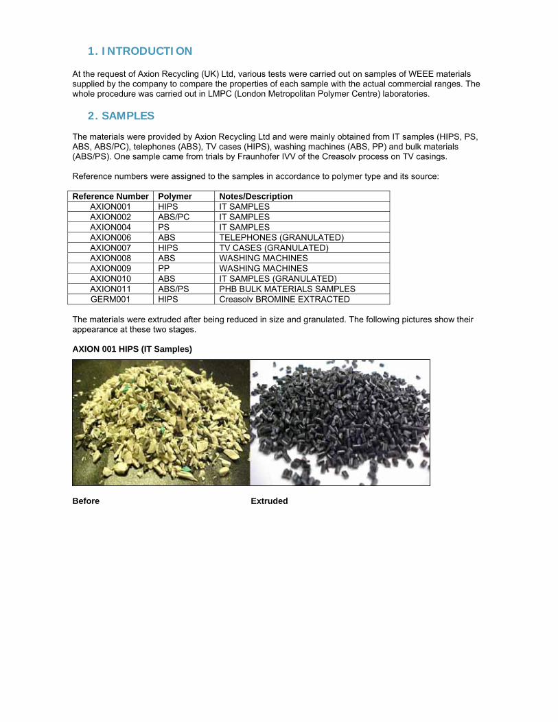
1. INTRODUCTION At the request of Axion Recycling (UK) Ltd, various tests were carried out on samples of WEEE materials supplied by the company to compare the properties of each sample with the actual commercial ranges. The whole procedure was carried out in LMPC (London Metropolitan Polymer Centre) laboratories.
2. SAMPLES The materials were provided by Axion Recycling Ltd and were mainly obtained from IT samples (HIPS, PS, ABS, ABS/PC), telephones (ABS), TV cases (HIPS), washing machines (ABS, PP) and bulk materials (ABS/PS). One sample came from trials by Fraunhofer IVV of the Creasolv process on TV casings. Reference numbers were assigned to the samples in accordance to polymer type and its source: Reference Number Polymer Notes/Description
AXION001 HIPS IT SAMPLES AXION002 ABS/PC IT SAMPLES AXION004 PS IT SAMPLES AXION006 ABS TELEPHONES (GRANULATED) AXION007 HIPS TV CASES (GRANULATED) AXION008 ABS WASHING MACHINES AXION009 PP WASHING MACHINES AXION010 ABS IT SAMPLES (GRANULATED) AXION011 ABS/PS PHB BULK MATERIALS SAMPLES GERM001 HIPS Creasolv BROMINE EXTRACTED
The materials were extruded after being reduced in size and granulated. The following pictures show their appearance at these two stages. AXION 001 HIPS (IT Samples)
Before Extruded
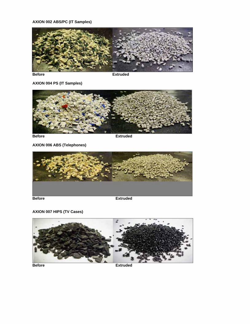
AXION 002 ABS/PC (IT Samples)
Before Extruded AXION 004 PS (IT Samples)
Before Extruded AXION 006 ABS (Telephones)
Before Extruded AXION 007 HIPS (TV Cases)
Before Extruded
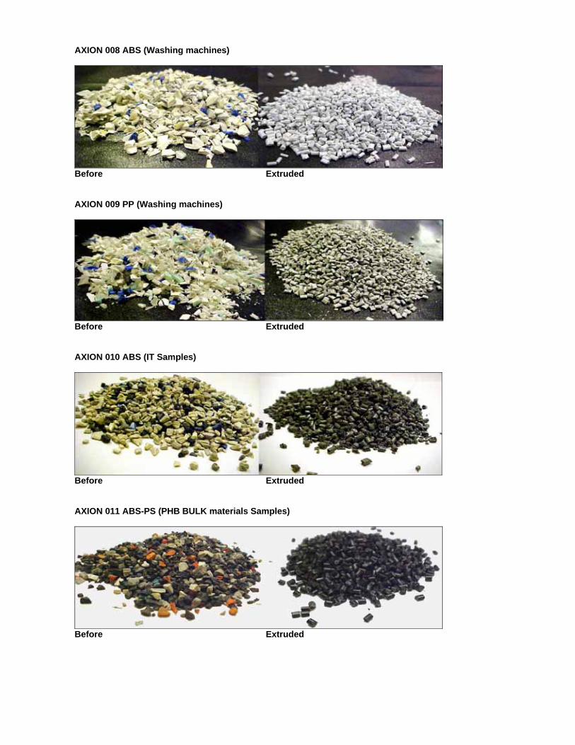
AXION 008 ABS (Washing machines)
Before Extruded AXION 009 PP (Washing machines)
Before Extruded AXION 010 ABS (IT Samples)
Before Extruded AXION 011 ABS-PS (PHB BULK materials Samples)
Before Extruded
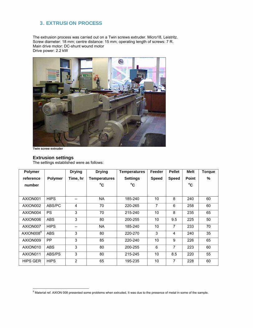
3. EXTRUSION PROCESS The extrusion process was carried out on a Twin screws extruder. Micro18, Leistritz. Screw diameter: 18 mm; centre distance: 15 mm; operating length of screws: 7 R. Main drive motor: DC-shunt wound motor Drive power: 2.2 kW
Twin screw extruder Extrusion settings The settings established were as follows:
Polymer reference number
Polymer
Drying Time, hr
Drying Temperatures
oC
Temperatures Settings
oC
Feeder Speed
Pellet Speed
Melt Point
oC
Torque %
AXION001 HIPS -- NA 185-240 10 8 240 60
AXION002 ABS/PC 4 70 220-265 7 6 258 60
AXION004 PS 3 70 215-240 10 8 235 65
AXION006 ABS 3 80 200-255 10 9.5 225 50
AXION007 HIPS -- NA 185-240 10 7 233 70
AXION0088 ABS 3 80 220-270 3 4 240 35
AXION009 PP 3 85 220-240 10 9 226 65
AXION010 ABS 3 80 200-255 6 7 223 60
AXION011 ABS/PS 3 80 215-245 10 8.5 220 55
HIPS GER HIPS 2 65 195-235 10 7 228 60
8 Material ref. AXION 008 presented some problems when extruded, It was due to the presence of metal in some of the sample.
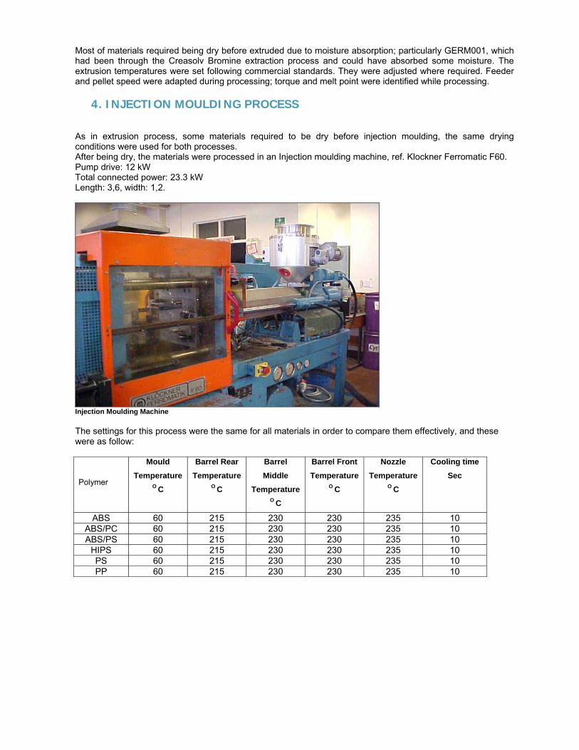
Most of materials required being dry before extruded due to moisture absorption; particularly GERM001, which had been through the Creasolv Bromine extraction process and could have absorbed some moisture. The extrusion temperatures were set following commercial standards. They were adjusted where required. Feeder and pellet speed were adapted during processing; torque and melt point were identified while processing.
4. INJECTION MOULDING PROCESS
As in extrusion process, some materials required to be dry before injection moulding, the same drying conditions were used for both processes. After being dry, the materials were processed in an Injection moulding machine, ref. Klockner Ferromatic F60. Pump drive: 12 kW Total connected power: 23.3 kW Length: 3,6, width: 1,2.
Injection Moulding Machine The settings for this process were the same for all materials in order to compare them effectively, and these were as follow: Polymer
Mould Temperature
O C
Barrel Rear Temperature
O C
Barrel Middle
Temperature O C
Barrel Front Temperature
O C
Nozzle Temperature
O C
Cooling time Sec
ABS 60 215 230 230 235 10 ABS/PC 60 215 230 230 235 10 ABS/PS 60 215 230 230 235 10
HIPS 60 215 230 230 235 10 PS 60 215 230 230 235 10 PP 60 215 230 230 235 10
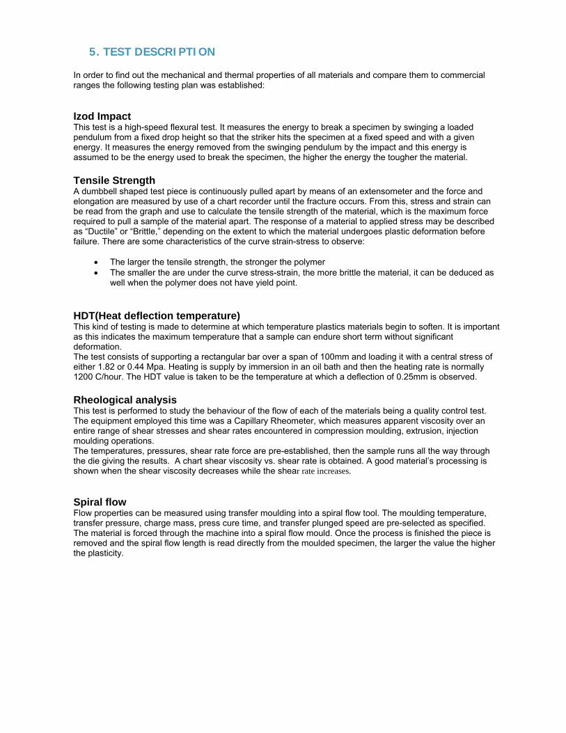
5. TEST DESCRIPTION In order to find out the mechanical and thermal properties of all materials and compare them to commercial ranges the following testing plan was established: Izod Impact This test is a high-speed flexural test. It measures the energy to break a specimen by swinging a loaded pendulum from a fixed drop height so that the striker hits the specimen at a fixed speed and with a given energy. It measures the energy removed from the swinging pendulum by the impact and this energy is assumed to be the energy used to break the specimen, the higher the energy the tougher the material. Tensile Strength A dumbbell shaped test piece is continuously pulled apart by means of an extensometer and the force and elongation are measured by use of a chart recorder until the fracture occurs. From this, stress and strain can be read from the graph and use to calculate the tensile strength of the material, which is the maximum force required to pull a sample of the material apart. The response of a material to applied stress may be described as “Ductile” or “Brittle,” depending on the extent to which the material undergoes plastic deformation before failure. There are some characteristics of the curve strain-stress to observe:
• The larger the tensile strength, the stronger the polymer • The smaller the are under the curve stress-strain, the more brittle the material, it can be deduced as
well when the polymer does not have yield point. HDT(Heat deflection temperature) This kind of testing is made to determine at which temperature plastics materials begin to soften. It is important as this indicates the maximum temperature that a sample can endure short term without significant deformation. The test consists of supporting a rectangular bar over a span of 100mm and loading it with a central stress of either 1.82 or 0.44 Mpa. Heating is supply by immersion in an oil bath and then the heating rate is normally 1200 C/hour. The HDT value is taken to be the temperature at which a deflection of 0.25mm is observed. Rheological analysis This test is performed to study the behaviour of the flow of each of the materials being a quality control test. The equipment employed this time was a Capillary Rheometer, which measures apparent viscosity over an entire range of shear stresses and shear rates encountered in compression moulding, extrusion, injection moulding operations. The temperatures, pressures, shear rate force are pre-established, then the sample runs all the way through the die giving the results. A chart shear viscosity vs. shear rate is obtained. A good material’s processing is shown when the shear viscosity decreases while the shear rate increases. Spiral flow Flow properties can be measured using transfer moulding into a spiral flow tool. The moulding temperature, transfer pressure, charge mass, press cure time, and transfer plunged speed are pre-selected as specified. The material is forced through the machine into a spiral flow mould. Once the process is finished the piece is removed and the spiral flow length is read directly from the moulded specimen, the larger the value the higher the plasticity.
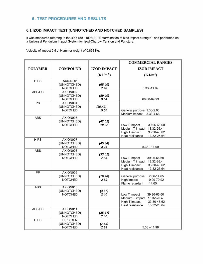
6. TEST PROCEDURES AND RESULTS 6.1 IZOD IMPACT TEST (UNNOTCHED AND NOTCHED SAMPLES) It was measured referring to the ISO 180 : 1993(E) “ Determination of Izod impact strength” and performed on a Universal Pendulum Impact System for Izod-Charpy- Tension and Puncture.
Velocity of impact 5.5 J, Hammer weight of 0.898 Kg.
POLYMER
COMPOUND
IZOD IMPACT
(KJ/m2 )
COMMERCIAL RANGES
IZOD IMPACT
(KJ/m2) HIPS AXION001
(UNNOTCHED) NOTCHED
(65.40)
7.98
5.33 -11.99 ABS/PC AXION002
(UNNOTCHED) NOTCHED
(89.40)
9.04
68.60-69.93 PS AXION004
(UNNOTCHED) NOTCHED
(30.42)
5.66
General purpose 1.33-2.66 Medium impact 3.33-4.66
ABS AXION006 (UNNOTCHED)
NOTCHED
(42.02) 10.52
Low T impact 39.96-66.60 Medium T impact 13.32-26.4 High T impact 33.30-46.62 Heat resistance 13.32-26.64
HIPS AXION007 (UNNOTCHED)
NOTCHED
(45.34)
3.26
5.33 –11.99 ABS AXION008
(UNNOTCHED) NOTCHED
(33.01)
7.85
Low T impact 39.96-66.60 Medium T impact 13.32-26.4 High T impact 33.30-46.62 Heat resistance 13.32-26.64
PP AXION009 (UNNOTCHED)
NOTCHED
(16.70)
2.59
General purpose 2.66-14.65 High impact 9.99-79.92 Flame retardant 14.65
ABS AXION010 (UNNOTCHED)
NOTCHED
(4.87) 2.40
Low T impact 39.96-66.60 Medium T impact 13.32-26.4 High T impact 33.30-46.62 Heat resistance 13.32-26.64
ABS/PS AXION011 (UNNOTCHED)
NOTCHED
(25.37)
7.40
HIPS HIPS GER (UNNOTCHED)
NOTCHED
(7.88) 2.88
5.33 –11.99
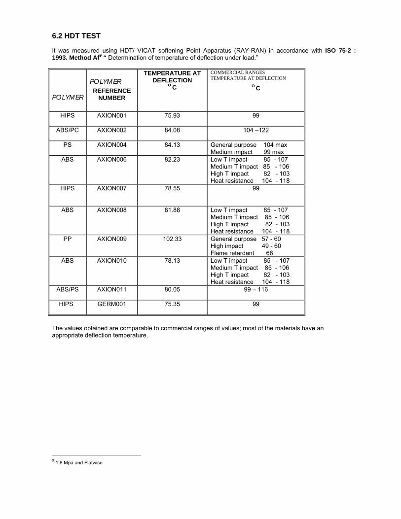
6.2 HDT TEST It was measured using HDT/ VICAT softening Point Apparatus (RAY-RAN) in accordance with ISO 75-2 : 1993. Method Af9 “ Determination of temperature of deflection under load.”
POLYMER
POLYMER REFERENCE
NUMBER
TEMPERATURE AT DEFLECTION
O C
COMMERCIAL RANGES TEMPERATURE AT DEFLECTION
O C
HIPS AXION001 75.93
99
ABS/PC AXION002 84.08
104 –122
PS AXION004 84.13
General purpose 104 max Medium impact 99 max
ABS AXION006 82.23
Low T impact 85 - 107 Medium T impact 85 - 106 High T impact 82 - 103 Heat resistance 104 - 118
HIPS AXION007 78.55
99
ABS AXION008 81.88
Low T impact 85 - 107 Medium T impact 85 - 106 High T impact 82 - 103 Heat resistance 104 - 118
PP AXION009 102.33
General purpose 57 - 60 High impact 49 - 60 Flame retardant 68
ABS AXION010 78.13
Low T impact 85 - 107 Medium T impact 85 - 106 High T impact 82 - 103 Heat resistance 104 - 118
ABS/PS
AXION011 80.05
99 – 116
HIPS
GERM001 75.35
99
The values obtained are comparable to commercial ranges of values; most of the materials have an appropriate deflection temperature.
9 1.8 Mpa and Flatwise
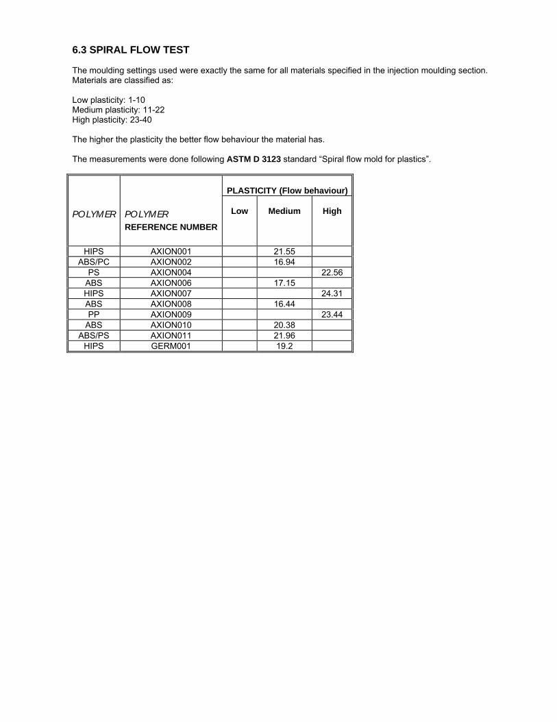
6.3 SPIRAL FLOW TEST The moulding settings used were exactly the same for all materials specified in the injection moulding section. Materials are classified as: Low plasticity: 1-10 Medium plasticity: 11-22 High plasticity: 23-40 The higher the plasticity the better flow behaviour the material has. The measurements were done following ASTM D 3123 standard “Spiral flow mold for plastics”.
PLASTICITY (Flow behaviour)
POLYMER
POLYMER REFERENCE NUMBER
Low
Medium
High
HIPS AXION001 21.55 ABS/PC AXION002 16.94
PS AXION004 22.56 ABS AXION006 17.15 HIPS AXION007 24.31 ABS AXION008 16.44 PP AXION009 23.44
ABS AXION010 20.38 ABS/PS AXION011 21.96
HIPS GERM001 19.2
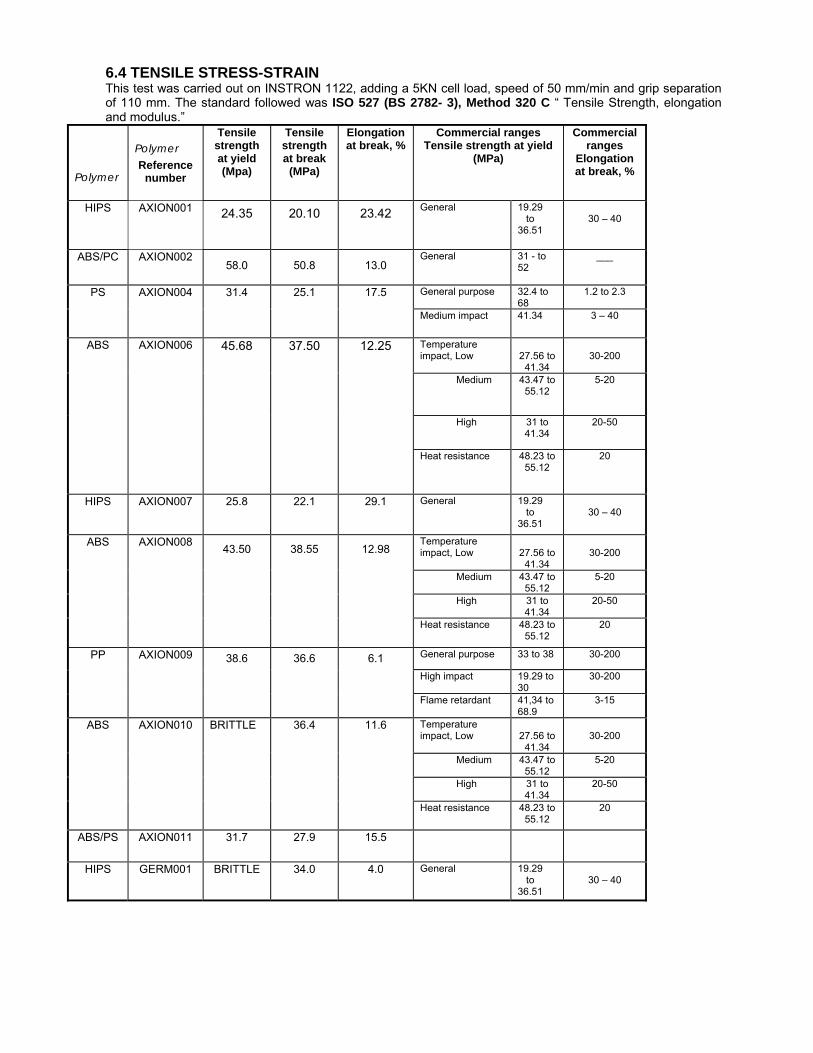
6.4 TENSILE STRESS-STRAIN This test was carried out on INSTRON 1122, adding a 5KN cell load, speed of 50 mm/min and grip separation of 110 mm. The standard followed was ISO 527 (BS 2782- 3), Method 320 C “ Tensile Strength, elongation and modulus.”
Polymer
Polymer Reference
number
Tensile strength at yield (Mpa)
Tensile strength at break (MPa)
Elongation at break, %
Commercial ranges Tensile strength at yield
(MPa)
Commercial ranges
Elongation at break, %
HIPS AXION001 24.35
20.10
23.42
General
19.29 to 36.51
30 – 40
ABS/PC
AXION002 58.0
50.8
13.0
General 31 - to 52
___
General purpose
32.4 to 68
1.2 to 2.3 PS AXION004 31.4
25.1
17.5
Medium impact 41.34 3 – 40
Temperature impact, Low
27.56 to
41.34
30-200
Medium 43.47 to 55.12
5-20
High 31 to 41.34
20-50
ABS AXION006 45.68 37.50 12.25
Heat resistance
48.23 to 55.12
20
HIPS AXION007 25.8
22.1
29.1
General 19.29 to 36.51
30 – 40
Temperature impact, Low
27.56 to
41.34
30-200
Medium 43.47 to 55.12
5-20
High 31 to 41.34
20-50
ABS AXION008 43.50
38.55
12.98
Heat resistance
48.23 to 55.12
20
General purpose 33 to 38 30-200
High impact 19.29 to 30
30-200
PP AXION009 38.6
36.6
6.1
Flame retardant
41,34 to 68.9
3-15
Temperature impact, Low
27.56 to
41.34
30-200
Medium 43.47 to 55.12
5-20
High 31 to 41.34
20-50
ABS AXION010 BRITTLE
36.4
11.6
Heat resistance 48.23 to 55.12
20
ABS/PS
AXION011 31.7
27.9
15.5
HIPS
GERM001 BRITTLE
34.0
4.0
General 19.29 to 36.51
30 – 40
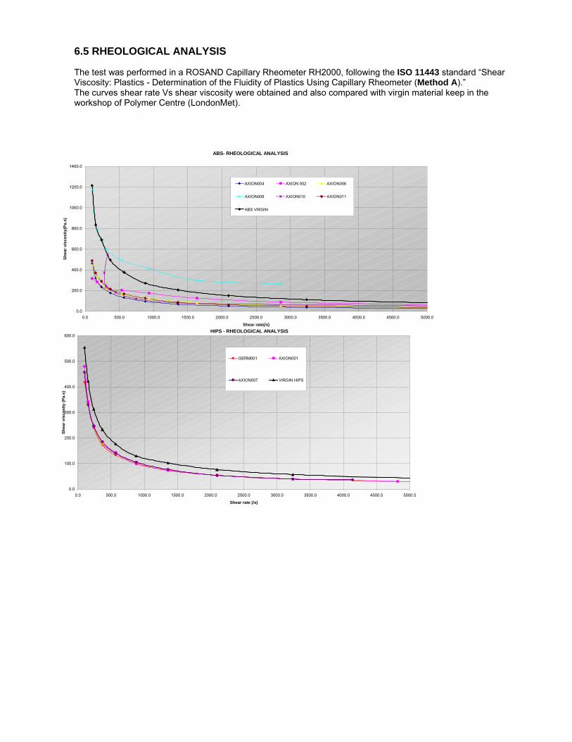
6.5 RHEOLOGICAL ANALYSIS The test was performed in a ROSAND Capillary Rheometer RH2000, following the ISO 11443 standard “Shear Viscosity: Plastics - Determination of the Fluidity of Plastics Using Capillary Rheometer (Method A).” The curves shear rate Vs shear viscosity were obtained and also compared with virgin material keep in the workshop of Polymer Centre (LondonMet).
ABS- RHEOLOGICAL ANALYSIS
0.0
200.0
400.0
600.0
800.0
1000.0
1200.0
1400.0
0.0 500.0 1000.0 1500.0 2000.0 2500.0 3000.0 3500.0 4000.0 4500.0 5000.0
Shear rate(/s)
Shea
r vis
cosi
ty(P
a.s)
AXION004 AXION 002 AXION006
AXION008 AXION010 AXION011
ABS VIRGIN
HIPS - RHEOLOGICAL ANALYSIS
0.0
100.0
200.0
300.0
400.0
500.0
600.0
0.0 500.0 1000.0 1500.0 2000.0 2500.0 3000.0 3500.0 4000.0 4500.0 5000.0
Shear rate (/s)
Shea
r vis
cosi
ty (P
a.s)
GERM001 AXION001
AXION007 VIRGIN HIPS
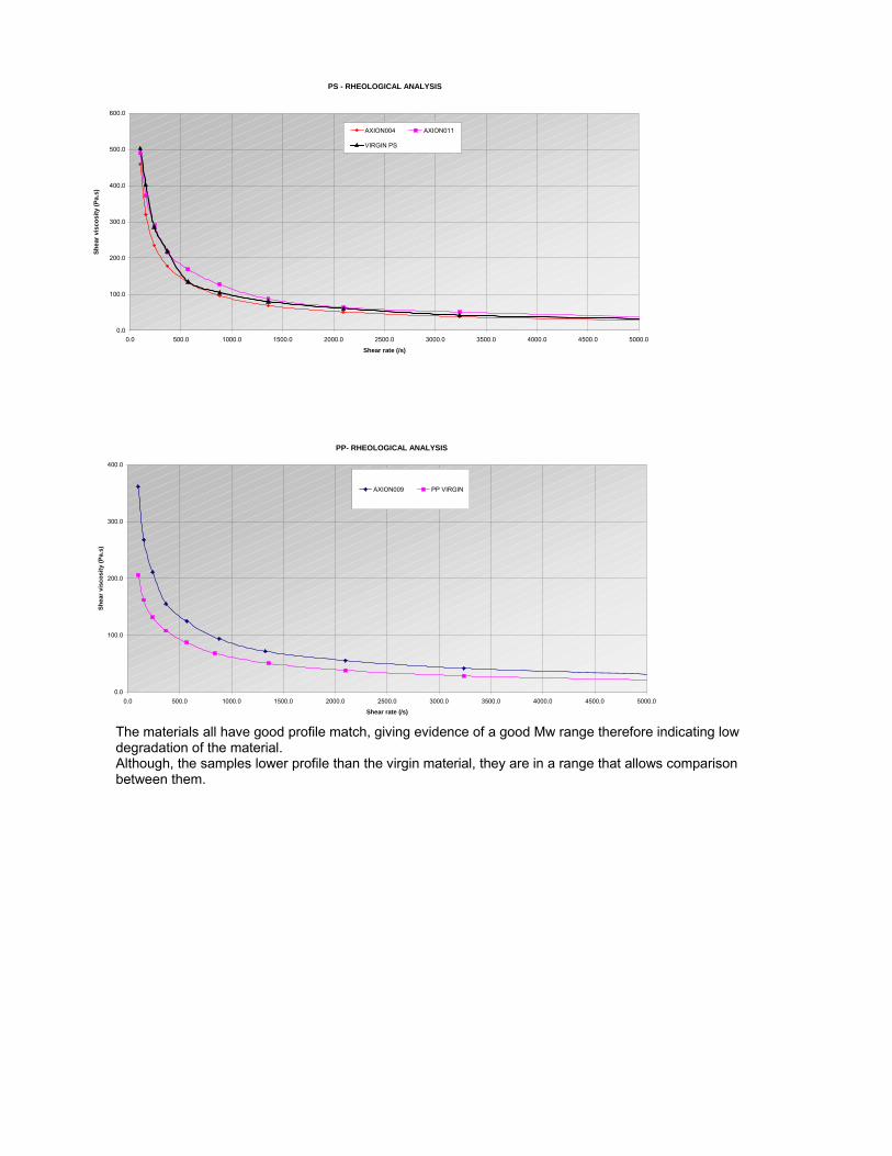
The materials all have good profile match, giving evidence of a good Mw range therefore indicating low degradation of the material. Although, the samples lower profile than the virgin material, they are in a range that allows comparison between them.
PS - RHEOLOGICAL ANALYSIS
0.0
100.0
200.0
300.0
400.0
500.0
600.0
0.0 500.0 1000.0 1500.0 2000.0 2500.0 3000.0 3500.0 4000.0 4500.0 5000.0
Shear rate (/s)
Shea
r vis
cosi
ty (P
a.s)
AXION004 AXION011
VIRGIN PS
PP- RHEOLOGICAL ANALYSIS
0.0
100.0
200.0
300.0
400.0
0.0 500.0 1000.0 1500.0 2000.0 2500.0 3000.0 3500.0 4000.0 4500.0 5000.0
Shear rate (/s)
Shea
r vis
cosi
ty (P
a.s)
AXION009 PP VIRGIN
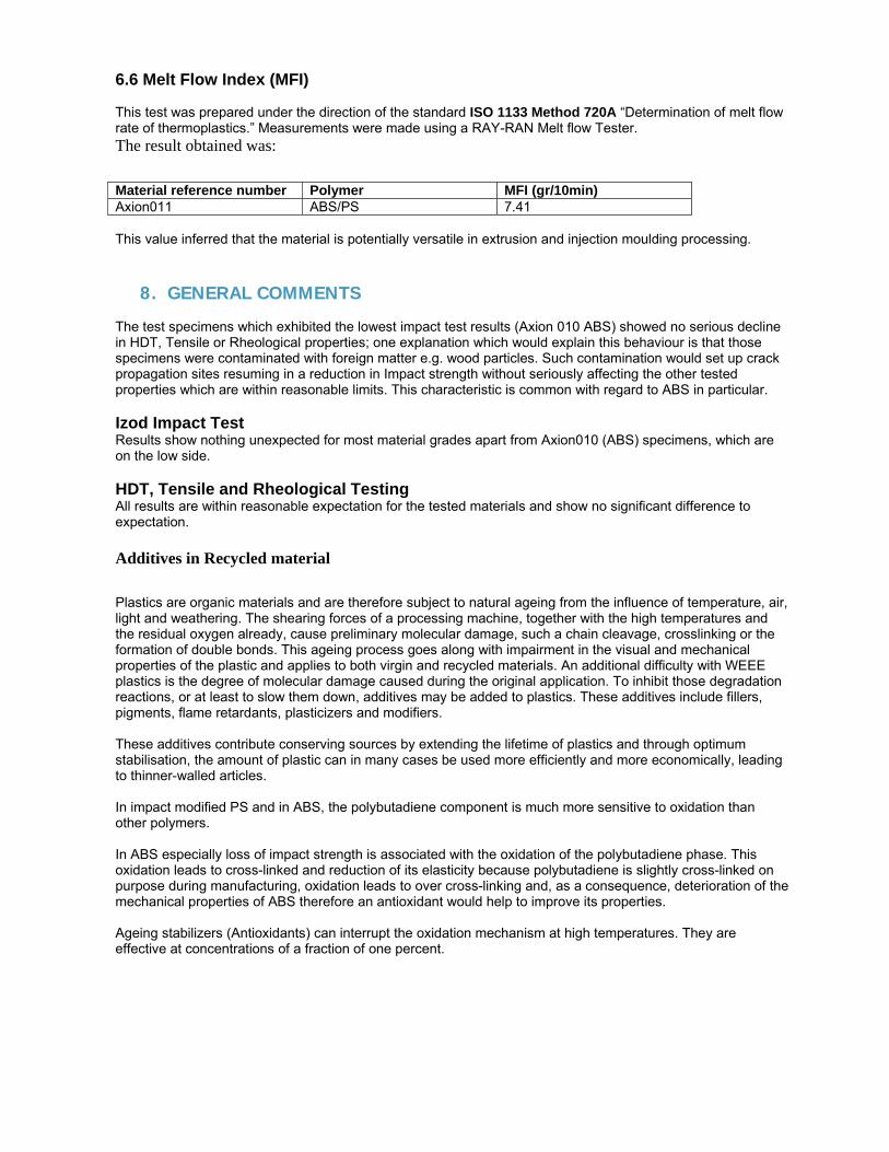
6.6 Melt Flow Index (MFI) This test was prepared under the direction of the standard ISO 1133 Method 720A “Determination of melt flow rate of thermoplastics.” Measurements were made using a RAY-RAN Melt flow Tester. The result obtained was:
Material reference number Polymer MFI (gr/10min) Axion011 ABS/PS 7.41 This value inferred that the material is potentially versatile in extrusion and injection moulding processing.
8. GENERAL COMMENTS The test specimens which exhibited the lowest impact test results (Axion 010 ABS) showed no serious decline in HDT, Tensile or Rheological properties; one explanation which would explain this behaviour is that those specimens were contaminated with foreign matter e.g. wood particles. Such contamination would set up crack propagation sites resuming in a reduction in Impact strength without seriously affecting the other tested properties which are within reasonable limits. This characteristic is common with regard to ABS in particular. Izod Impact Test Results show nothing unexpected for most material grades apart from Axion010 (ABS) specimens, which are on the low side. HDT, Tensile and Rheological Testing All results are within reasonable expectation for the tested materials and show no significant difference to expectation. Additives in Recycled material
Plastics are organic materials and are therefore subject to natural ageing from the influence of temperature, air, light and weathering. The shearing forces of a processing machine, together with the high temperatures and the residual oxygen already, cause preliminary molecular damage, such a chain cleavage, crosslinking or the formation of double bonds. This ageing process goes along with impairment in the visual and mechanical properties of the plastic and applies to both virgin and recycled materials. An additional difficulty with WEEE plastics is the degree of molecular damage caused during the original application. To inhibit those degradation reactions, or at least to slow them down, additives may be added to plastics. These additives include fillers, pigments, flame retardants, plasticizers and modifiers. These additives contribute conserving sources by extending the lifetime of plastics and through optimum stabilisation, the amount of plastic can in many cases be used more efficiently and more economically, leading to thinner-walled articles. In impact modified PS and in ABS, the polybutadiene component is much more sensitive to oxidation than other polymers. In ABS especially loss of impact strength is associated with the oxidation of the polybutadiene phase. This oxidation leads to cross-linked and reduction of its elasticity because polybutadiene is slightly cross-linked on purpose during manufacturing, oxidation leads to over cross-linking and, as a consequence, deterioration of the mechanical properties of ABS therefore an antioxidant would help to improve its properties. Ageing stabilizers (Antioxidants) can interrupt the oxidation mechanism at high temperatures. They are effective at concentrations of a fraction of one percent.
Report on testing of final products from large scale Creasolv and Centrevap process trials in Phase 3
Melt Flow Rate, Heat Deflection Temperature, Tensile and Impact Strength
Analysis
Recycled HIPS Samples
Report No. 2037
Client: Axion Recycling Ltd Attention: Roger Morton Reported by: Anna Arkhireeva Polymer Centre London Metropolitan University Date of report: 21 August 2006
1. Introduction At the request of Dr Roger Morton of Axion Recycling Ltd, Melt Flow Rate, Heat Deflection Temperature, Impact and Tensile Strength measurements were performed for 4 recycled HIPS samples. 2. Experimental The test samples were injection moulded using a Klockner Ferromatic F60 injection moulding machine. For samples AX 06 007 and 008, the barrel temperature was between 2150C (nozzle) and 2000C (rear), for AX 06 006, between 1950C and 1850C, respectively, and for AX 06 009, between 2250C and 2100C. The mould temperature of 300C was used for AX 06 006 sample and for samples AX 06 007, 008 and 009 the mould temperature was 400C. The materials were dried prior to moulding for approximately 1.5 hours at 700C All the tests were performed at 22-230C, at ca. 40% humidity. Izod impact tests were performed using a Ray-Ran Pendulum Impact system with the hammer weight of 0.898 kg at velocity of 3.5 m/s. The standard specimen measures 80 x 10 x 4 mm. For the notched geometry of the specimens, the depth under the notch is 8 mm. At least 8 specimens were used for each individual test. The tests were performed according to ISO 180:1993(E) standard. Melt Flow Rate measurements were carried out using a standard Davenport melt flow indexer equipped with a Eurotherm temperature controller in accordance with BS EN ISO 1133:2000 BS2782-7:Method 720A at 2000C using the weight of 5.0 kg. Tensile measurements were carried out on a Tinius Olsen H10KS tensometer at 50 mm/min using the grip distance of 115 mm and the gauge length of 50 mm. 6-8 dumb-bell specimens were used for each compound. ISO 527 (BS 2782-3) standard was used. HDT tests were performed on a Ray-Ran HDT-Vicat softening point apparatus using flatwise specimen orientation (80 x 10 x 4 mm) with the temperature ramp rate of 1200C/hour. The fibre stress of 1.8 MPa was used. The tests were carried out according to ISO 75-2:1993 standard. 3. Results Some signs of plate-out are seen in mouldings produced with AX 06 007 (Fig. 1) and 008 compounds, thus suggesting that these materials are contaminated with some additives/polymers that are incompatible with HIPS. The best processibility and quality of the mouldings were observed for AX 06 009 sample (Fig. 2). Both tensile and impact test pieces fractured in the way similar to that expected for virgin HIPS samples. The results of the Izod impact tests show a considerable separation between the values obtained for the notched and unnotched geometry. This observation suggests that the materials studied here are quite sensitive to defects and flaws. Typical tensile load-displacement curves were obtained for all the compounds. These curves show that tensile fracture of these samples involves necking and cold-drawing. Stress whitening was clearly seen during the test. However, this stress-whitened zone ‘healed’ after the fracture was completed. The only notable feature is that for AX 06 009 sample the gap between the yield
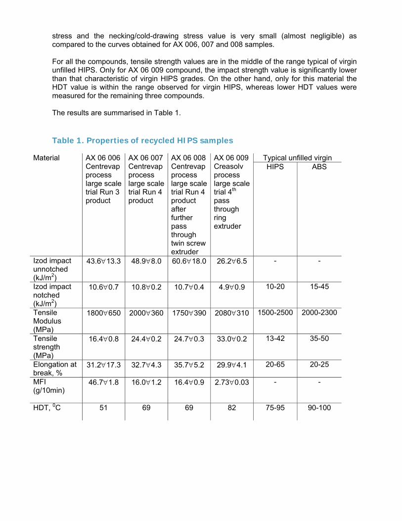
stress and the necking/cold-drawing stress value is very small (almost negligible) as compared to the curves obtained for AX 006, 007 and 008 samples. For all the compounds, tensile strength values are in the middle of the range typical of virgin unfilled HIPS. Only for AX 06 009 compound, the impact strength value is significantly lower than that characteristic of virgin HIPS grades. On the other hand, only for this material the HDT value is within the range observed for virgin HIPS, whereas lower HDT values were measured for the remaining three compounds. The results are summarised in Table 1. Table 1. Properties of recycled HIPS samples
Typical unfilled virgin Material
AX 06 006 Centrevap process large scale trial Run 3 product
AX 06 007 Centrevap process large scale trial Run 4 product
AX 06 008 Centrevap process large scale trial Run 4 product after further pass through twin screw extruder
AX 06 009 Creasolv process large scale trial 4th pass through ring extruder
HIPS ABS
Izod impact unnotched (kJ/m2)
43.6∀13.3 48.9∀8.0 60.6∀18.0 26.2∀6.5 - -
Izod impact notched (kJ/m2)
10.6∀0.7 10.8∀0.2 10.7∀0.4 4.9∀0.9 10-20 15-45
Tensile Modulus (MPa)
1800∀650 2000∀360 1750∀390 2080∀310 1500-2500 2000-2300
Tensile strength (MPa)
16.4∀0.8 24.4∀0.2 24.7∀0.3 33.0∀0.2 13-42 35-50
Elongation at break, %
31.2∀17.3 32.7∀4.3 35.7∀5.2 29.9∀4.1 20-65 20-25
MFI (g/10min)
46.7∀1.8 16.0∀1.2 16.4∀0.9 2.73∀0.03 - -
HDT, 0C
51 69 69 82 75-95 90-100
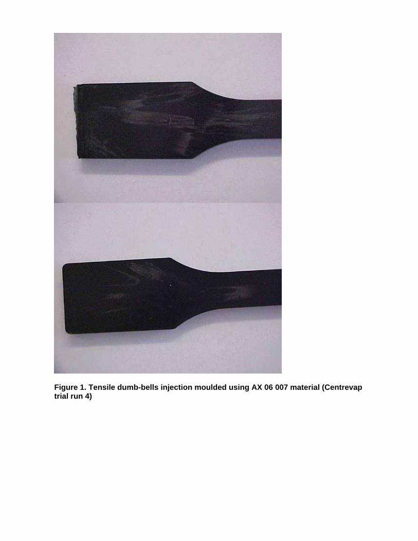
Figure 1. Tensile dumb-bells injection moulded using AX 06 007 material (Centrevap trial run 4)
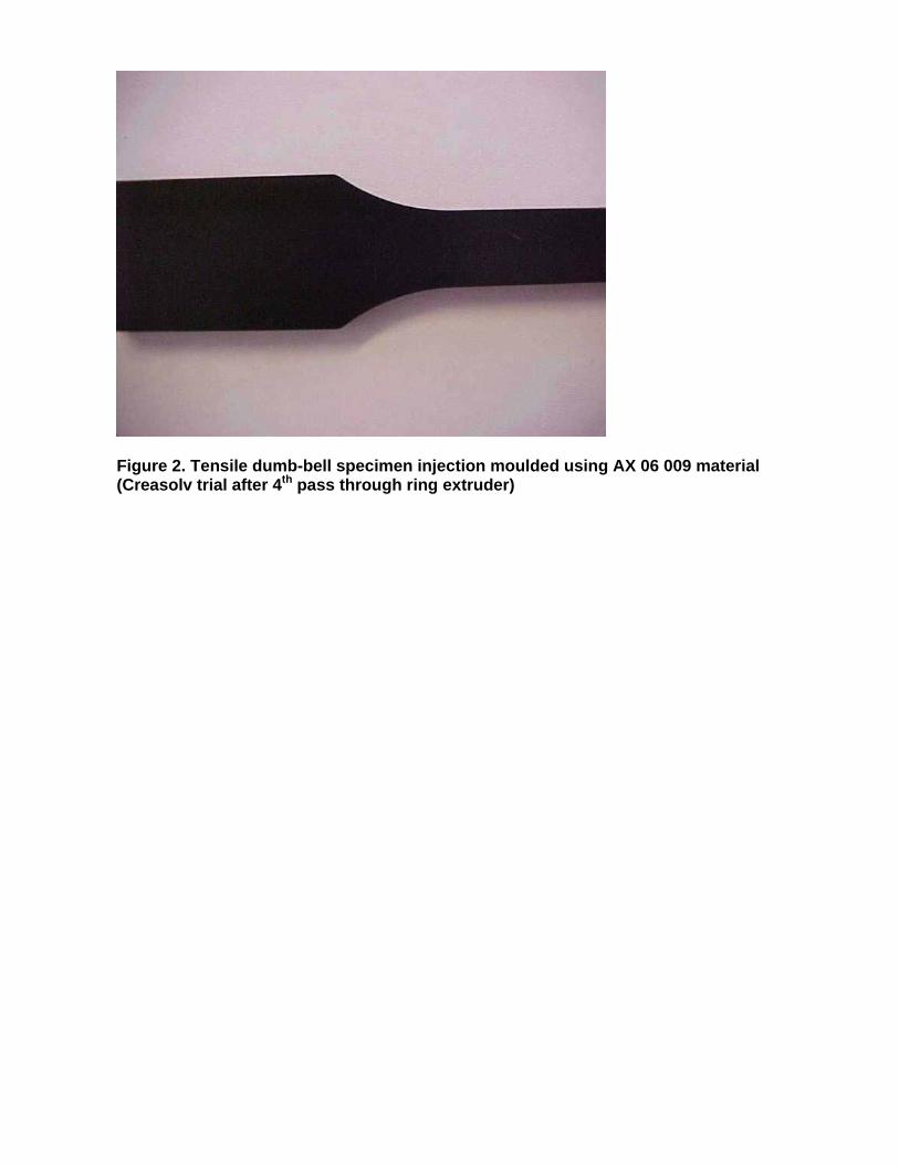
Figure 2. Tensile dumb-bell specimen injection moulded using AX 06 009 material (Creasolv trial after 4th pass through ring extruder)
Further report on testing of final product from large scale Creasolv process trials in Phase 3
Melt Flow Rate, Heat Deflection Temperature, Tensile and Impact Strength
Analysis
Recycled HIPS Sample
Report No. 2046
Client: Axion Recycling Ltd Attention: Roger Morton Reported by: Anna Arkhireeva Polymer Centre London Metropolitan University Date of report: 4 October 2006
1. Introduction At the request of Dr Roger Morton of Axion Recycling Ltd, Melt Flow Rate, Heat Deflection Temperature, Impact and Tensile Strength measurements were performed for a recycled HIPS sample. 2. Experimental The test samples were injection moulded using a Klockner Ferromatic F60 injection moulding machine. The barrel temperature was between 2150C (nozzle) and 2000C (rear) and the mould temperature of 400C was used. The material was dried prior to moulding for approximately 1.5 hours at 700C All the tests were performed at 20-220C, at ca. 40% humidity. Izod impact tests were performed using a Ray-Ran Pendulum Impact system with the hammer weight of 0.898 kg at velocity of 3.5 m/s. The standard specimen measures 80 x 10 x 4 mm. For the notched geometry of the specimens, the depth under the notch is 8 mm. 12 specimens were used for each individual test. The tests were performed according to ISO 180:1993(E) standard. Melt Flow Rate measurements were carried out using a standard Davenport melt flow indexer equipped with a Eurotherm temperature controller in accordance with BS EN ISO 1133:2000 BS2782-7:Method 720A at 2000C using the weight of 5.0 kg. Tensile measurements were carried out on a Tinius Olsen H10KS tensometer at 50 mm/min using the grip distance of 115 mm and the gauge length of 50 mm. 10 dumb-bell specimens were used. ISO 527 (BS 2782-3) standard was used. HDT tests were performed on a Ray-Ran HDT-Vicat softening point apparatus using flatwise specimen orientation (80 x 10 x 4 mm) with the temperature ramp rate of 1200C/hour. The fibre stress of 1.8 MPa was used. The tests were carried out according to ISO 75-2:1993 standard.
3. Results The results are summarised in Table 1.
Table 1. Properties of recycled HIPS sample
Material
AX 06 50 Creasolv process
large scale trial 3rd pass through ring extruder
Izod impact unnotched (kJ/m2)
26.37∀4.22
Izod impact notched (kJ/m2)
5.73∀0.49
Tensile Modulus (MPa)
2280∀160
Tensile strength (MPa)
30.7∀0.1
Elongation at break, %
15.6∀4.2
MFI (g/10min)
3.86∀0.01
HDT, 0C
80∀1
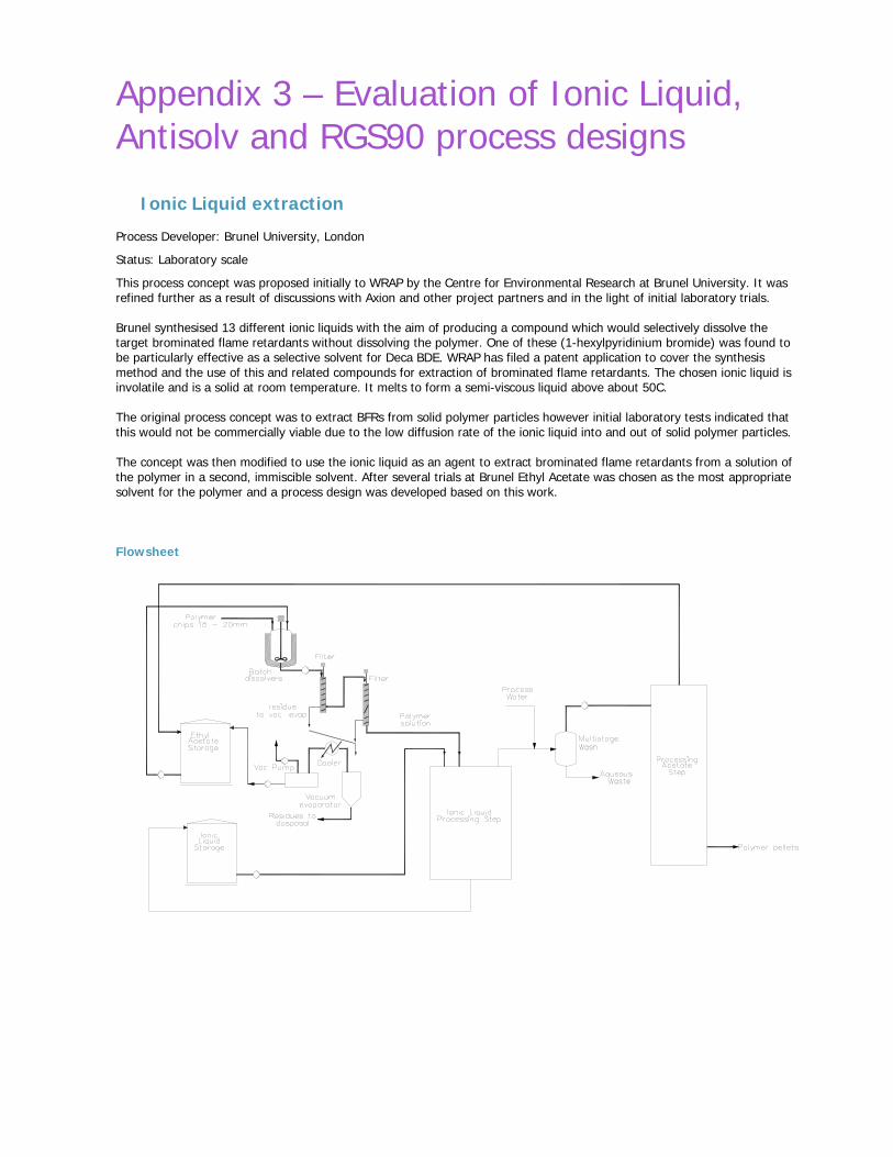
Appendix 3 – Evaluation of Ionic Liquid, Antisolv and RGS90 process designs
Ionic Liquid extraction Process Developer: Brunel University, London
Status: Laboratory scale
This process concept was proposed initially to WRAP by the Centre for Environmental Research at Brunel University. It was refined further as a result of discussions with Axion and other project partners and in the light of initial laboratory trials. Brunel synthesised 13 different ionic liquids with the aim of producing a compound which would selectively dissolve the target brominated flame retardants without dissolving the polymer. One of these (1-hexylpyridinium bromide) was found to be particularly effective as a selective solvent for Deca BDE. WRAP has filed a patent application to cover the synthesis method and the use of this and related compounds for extraction of brominated flame retardants. The chosen ionic liquid is involatile and is a solid at room temperature. It melts to form a semi-viscous liquid above about 50C. The original process concept was to extract BFRs from solid polymer particles however initial laboratory tests indicated that this would not be commercially viable due to the low diffusion rate of the ionic liquid into and out of solid polymer particles. The concept was then modified to use the ionic liquid as an agent to extract brominated flame retardants from a solution of the polymer in a second, immiscible solvent. After several trials at Brunel Ethyl Acetate was chosen as the most appropriate solvent for the polymer and a process design was developed based on this work. Flowsheet
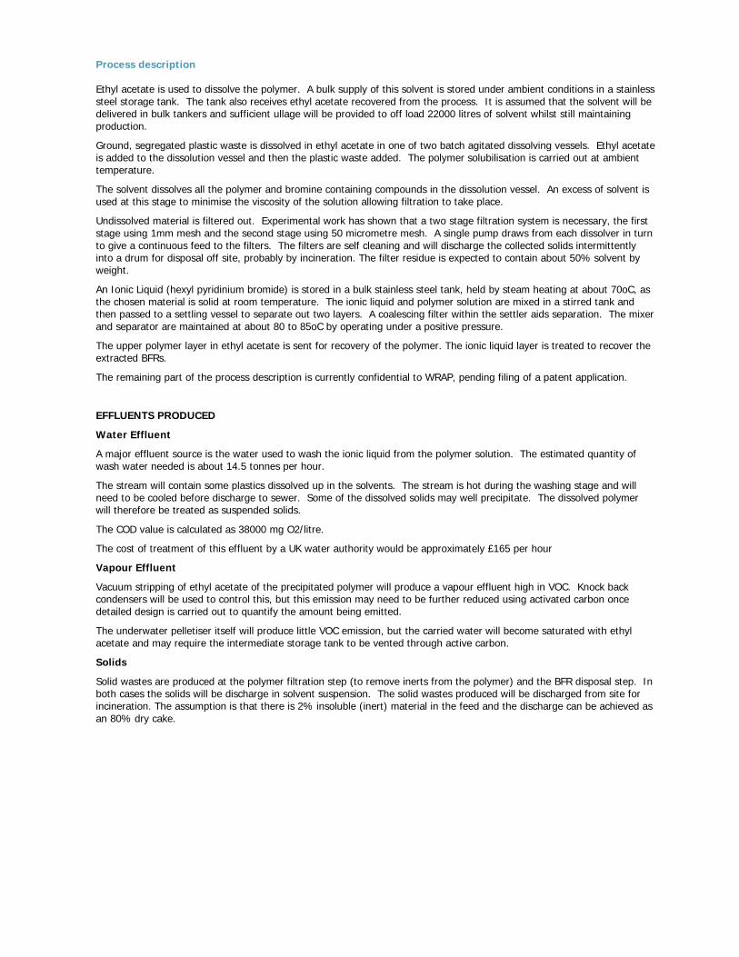
Process description Ethyl acetate is used to dissolve the polymer. A bulk supply of this solvent is stored under ambient conditions in a stainless steel storage tank. The tank also receives ethyl acetate recovered from the process. It is assumed that the solvent will be delivered in bulk tankers and sufficient ullage will be provided to off load 22000 litres of solvent whilst still maintaining production.
Ground, segregated plastic waste is dissolved in ethyl acetate in one of two batch agitated dissolving vessels. Ethyl acetate is added to the dissolution vessel and then the plastic waste added. The polymer solubilisation is carried out at ambient temperature.
The solvent dissolves all the polymer and bromine containing compounds in the dissolution vessel. An excess of solvent is used at this stage to minimise the viscosity of the solution allowing filtration to take place.
Undissolved material is filtered out. Experimental work has shown that a two stage filtration system is necessary, the first stage using 1mm mesh and the second stage using 50 micrometre mesh. A single pump draws from each dissolver in turn to give a continuous feed to the filters. The filters are self cleaning and will discharge the collected solids intermittently into a drum for disposal off site, probably by incineration. The filter residue is expected to contain about 50% solvent by weight.
An Ionic Liquid (hexyl pyridinium bromide) is stored in a bulk stainless steel tank, held by steam heating at about 70oC, as the chosen material is solid at room temperature. The ionic liquid and polymer solution are mixed in a stirred tank and then passed to a settling vessel to separate out two layers. A coalescing filter within the settler aids separation. The mixer and separator are maintained at about 80 to 85oC by operating under a positive pressure.
The upper polymer layer in ethyl acetate is sent for recovery of the polymer. The ionic liquid layer is treated to recover the extracted BFRs.
The remaining part of the process description is currently confidential to WRAP, pending filing of a patent application.
EFFLUENTS PRODUCED
Water Effluent
A major effluent source is the water used to wash the ionic liquid from the polymer solution. The estimated quantity of wash water needed is about 14.5 tonnes per hour.
The stream will contain some plastics dissolved up in the solvents. The stream is hot during the washing stage and will need to be cooled before discharge to sewer. Some of the dissolved solids may well precipitate. The dissolved polymer will therefore be treated as suspended solids.
The COD value is calculated as 38000 mg O2/litre.
The cost of treatment of this effluent by a UK water authority would be approximately £165 per hour
Vapour Effluent
Vacuum stripping of ethyl acetate of the precipitated polymer will produce a vapour effluent high in VOC. Knock back condensers will be used to control this, but this emission may need to be further reduced using activated carbon once detailed design is carried out to quantify the amount being emitted.
The underwater pelletiser itself will produce little VOC emission, but the carried water will become saturated with ethyl acetate and may require the intermediate storage tank to be vented through active carbon.
Solids
Solid wastes are produced at the polymer filtration step (to remove inerts from the polymer) and the BFR disposal step. In both cases the solids will be discharge in solvent suspension. The solid wastes produced will be discharged from site for incineration. The assumption is that there is 2% insoluble (inert) material in the feed and the discharge can be achieved as an 80% dry cake.
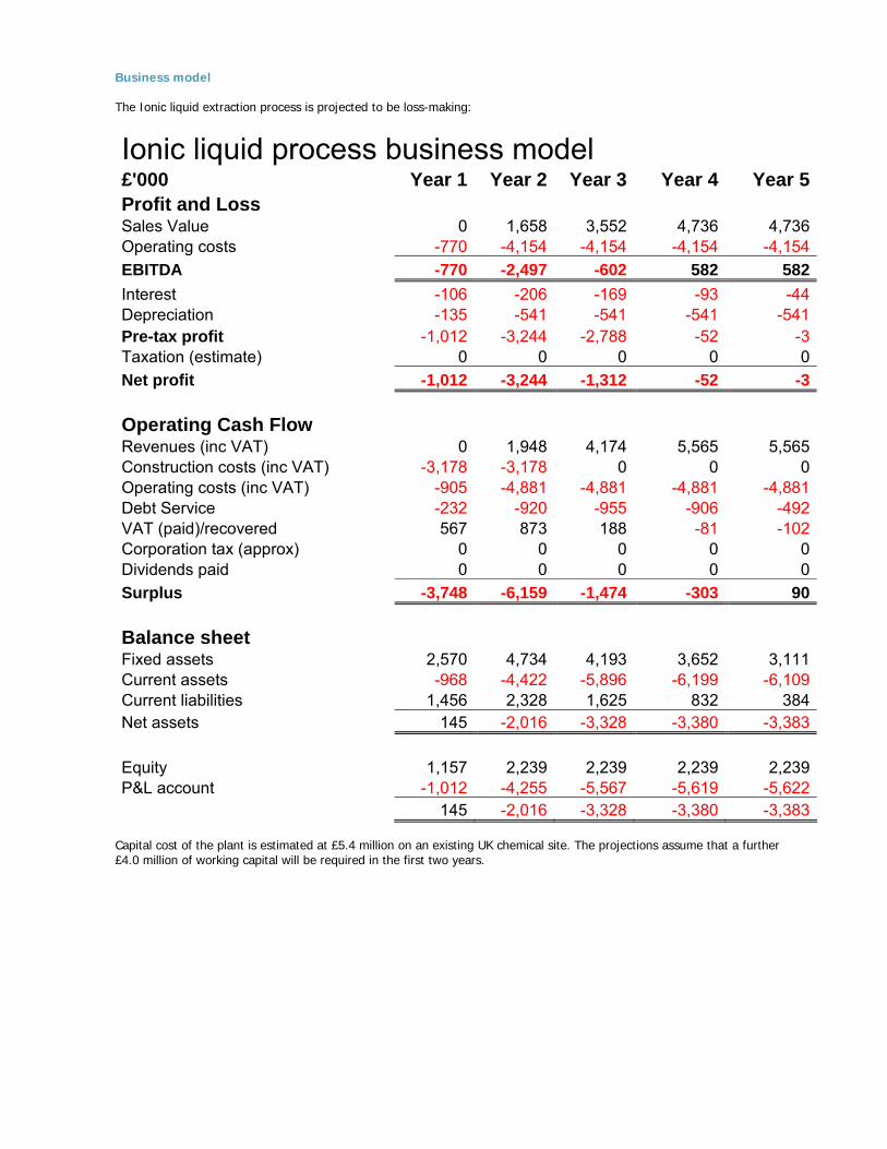
Business model The Ionic liquid extraction process is projected to be loss-making:
Ionic liquid process business model
£'000 Year 1 Year 2 Year 3 Year 4 Year 5Profit and Loss Sales Value 0 1,658 3,552 4,736 4,736Operating costs -770 -4,154 -4,154 -4,154 -4,154EBITDA -770 -2,497 -602 582 582Interest -106 -206 -169 -93 -44Depreciation -135 -541 -541 -541 -541Pre-tax profit -1,012 -3,244 -2,788 -52 -3Taxation (estimate) 0 0 0 0 0Net profit -1,012 -3,244 -1,312 -52 -3
Operating Cash Flow Revenues (inc VAT) 0 1,948 4,174 5,565 5,565Construction costs (inc VAT) -3,178 -3,178 0 0 0Operating costs (inc VAT) -905 -4,881 -4,881 -4,881 -4,881Debt Service -232 -920 -955 -906 -492VAT (paid)/recovered 567 873 188 -81 -102Corporation tax (approx) 0 0 0 0 0Dividends paid 0 0 0 0 0Surplus -3,748 -6,159 -1,474 -303 90
Balance sheet Fixed assets 2,570 4,734 4,193 3,652 3,111Current assets -968 -4,422 -5,896 -6,199 -6,109Current liabilities 1,456 2,328 1,625 832 384Net assets 145 -2,016 -3,328 -3,380 -3,383 Equity 1,157 2,239 2,239 2,239 2,239P&L account -1,012 -4,255 -5,567 -5,619 -5,622 145 -2,016 -3,328 -3,380 -3,383
Capital cost of the plant is estimated at £5.4 million on an existing UK chemical site. The projections assume that a further £4.0 million of working capital will be required in the first two years.

Discussion The ionic liquid developed by Brunel is a very efficient selective solvent for brominated flame retardants. The solvent has low volatility, which is a potential advantage. With further process development it could potentially produce an interesting process design. The current embodiment of the process generates too much effluent, consumes too much secondary solvent (ethyl acetate) and uses too much energy for commercial or environmental viability. The process design modelled is a scale up of the laboratory scale work done at Brunel. Despite considerable process design brainstorming by Axion and the rest of WRAP project team we were unable to identify design modifications which could simplify the process significantly or reduce its resource consumption. A further fundamental issue with this process is that the ionic liquid used is itself brominated. The process removes BFRs effectively but inevitably small amounts of ionic liquid will be left in the polymer, reintroducing bromine to the polymer Brunel tested other analogues of the chosen ionic liquid but none were as effective as the brominated version. The business model indicates that the process is likely to generate substantial annual losses with the target gate fee of £45/te.
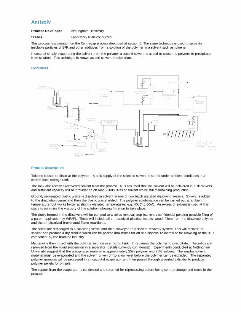
Antisolv Process Developer Nottingham University
Status Laboratory trials conducted
This process is a variation on the Centrevap process described at section 0. The same technique is used to separate insoluble particles of BFR and other additives from a solution of the polymer in a solvent such as toluene.
Instead of simply evaporating the solvent from the polymer a second solvent is added to cause the polymer to precipitate from solution. This technique is known as anti solvent precipitation.
Flowsheet
Process description Toluene is used to dissolve the polymer. A bulk supply of the selected solvent is stored under ambient conditions in a carbon steel storage tank.
The tank also receives recovered solvent from the process. It is assumed that the solvent will be delivered in bulk tankers and sufficient capacity will be provided to off load 22000 litres of solvent whilst still maintaining production.
Ground, segregated plastic waste is dissolved in solvent in one of two batch agitated dissolving vessels. Solvent is added to the dissolution vessel and then the plastic waste added. The polymer solubilisation can be carried out at ambient temperature, but works better at slightly elevated temperatures, e.g. 40oC to 60oC. An excess of solvent is used at this stage to minimise the viscosity of the solution allowing filtration to take place.
The slurry formed in the dissolvers will be pumped to a solids removal step (currently confidential pending possible filing of a patent application by WRAP). These will include all un-dissolved plastics, metals, wood, fillers from the dissolved polymer and the un-dissolved brominated flame retardants.
The solids are discharged to a collecting vessel and then conveyed to a solvent recovery system. This will recover the solvent and produce a dry residue which can be packed into drums for off site disposal to landfill or for recycling of the BFR component by the bromine industry
Methanol is then mixed with the polymer solution in a mixing tank. This causes the polymer to precipitate. The solids are removed from the liquid suspension in a separator (details currently confidential). Experiments conducted at Nottingham University suggest that the precipitated material is approximately 25% polymer and 75% solvent. The surplus solvent material must be evaporated and the solvent driven off to a low level before the polymer can be extruded. The separated polymer granules will be processed in a horizontal evaporator and then passed through a vented extruder to produce polymer pellets for on sale.
The vapour from the evaporator is condensed and returned for reprocessing before being sent to storage and reuse in the process.
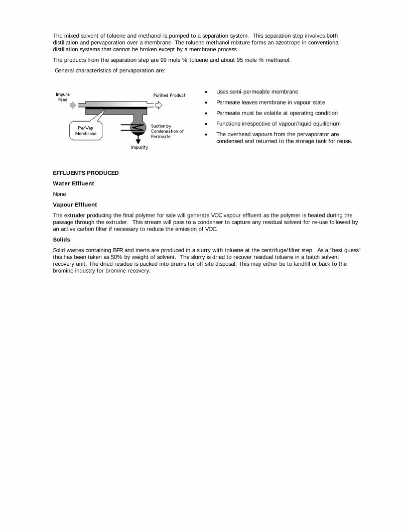
The mixed solvent of toluene and methanol is pumped to a separation system. This separation step involves both distillation and pervaporation over a membrane. The toluene methanol mixture forms an azeotrope in conventional distillation systems that cannot be broken except by a membrane process.
The products from the separation step are 99 mole % toluene and about 95 mole % methanol.
General characteristics of pervaporation are:
• Uses semi-permeable membrane
• Permeate leaves membrane in vapour state
• Permeate must be volatile at operating condition
• Functions irrespective of vapour/liquid equilibrium
• The overhead vapours from the pervaporator are condensed and returned to the storage tank for reuse.
EFFLUENTS PRODUCED
Water Effluent
None
Vapour Effluent
The extruder producing the final polymer for sale will generate VOC vapour effluent as the polymer is heated during the passage through the extruder. This stream will pass to a condenser to capture any residual solvent for re-use followed by an active carbon filter if necessary to reduce the emission of VOC.
Solids
Solid wastes containing BFR and inerts are produced in a slurry with toluene at the centrifuge/filter step. As a “best guess” this has been taken as 50% by weight of solvent. The slurry is dried to recover residual toluene in a batch solvent recovery unit. The dried residue is packed into drums for off site disposal. This may either be to landfill or back to the bromine industry for bromine recovery.
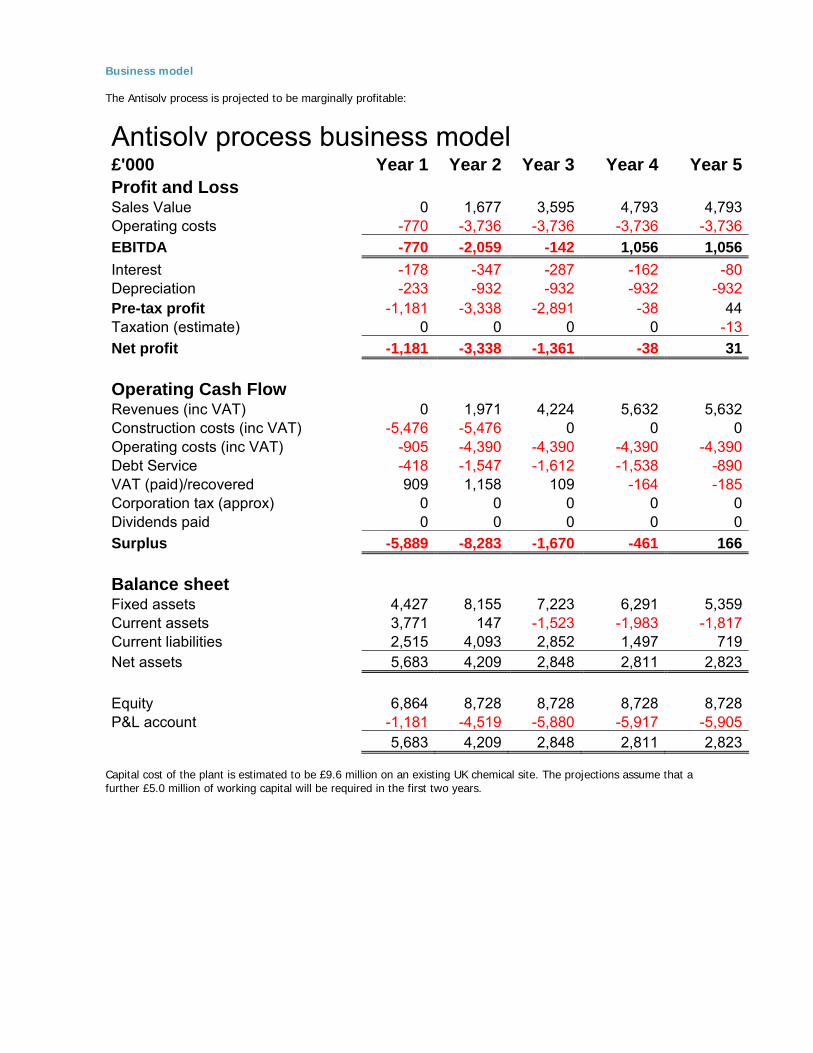
Business model The Antisolv process is projected to be marginally profitable:
Antisolv process business model
£'000 Year 1 Year 2 Year 3 Year 4 Year 5Profit and Loss Sales Value 0 1,677 3,595 4,793 4,793Operating costs -770 -3,736 -3,736 -3,736 -3,736EBITDA -770 -2,059 -142 1,056 1,056Interest -178 -347 -287 -162 -80Depreciation -233 -932 -932 -932 -932Pre-tax profit -1,181 -3,338 -2,891 -38 44Taxation (estimate) 0 0 0 0 -13Net profit -1,181 -3,338 -1,361 -38 31
Operating Cash Flow Revenues (inc VAT) 0 1,971 4,224 5,632 5,632Construction costs (inc VAT) -5,476 -5,476 0 0 0Operating costs (inc VAT) -905 -4,390 -4,390 -4,390 -4,390Debt Service -418 -1,547 -1,612 -1,538 -890VAT (paid)/recovered 909 1,158 109 -164 -185Corporation tax (approx) 0 0 0 0 0Dividends paid 0 0 0 0 0Surplus -5,889 -8,283 -1,670 -461 166
Balance sheet Fixed assets 4,427 8,155 7,223 6,291 5,359Current assets 3,771 147 -1,523 -1,983 -1,817Current liabilities 2,515 4,093 2,852 1,497 719Net assets 5,683 4,209 2,848 2,811 2,823 Equity 6,864 8,728 8,728 8,728 8,728P&L account -1,181 -4,519 -5,880 -5,917 -5,905 5,683 4,209 2,848 2,811 2,823
Capital cost of the plant is estimated to be £9.6 million on an existing UK chemical site. The projections assume that a further £5.0 million of working capital will be required in the first two years.
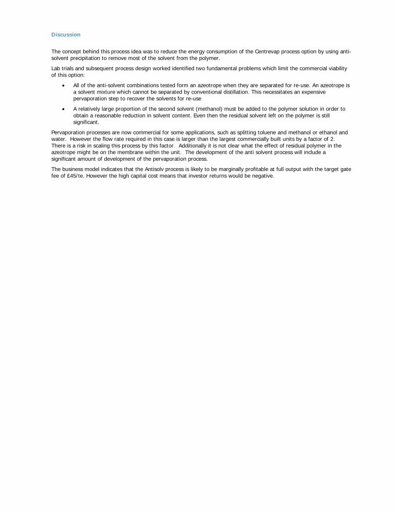
Discussion
The concept behind this process idea was to reduce the energy consumption of the Centrevap process option by using anti-solvent precipitation to remove most of the solvent from the polymer.
Lab trials and subsequent process design worked identified two fundamental problems which limit the commercial viability of this option:
• All of the anti-solvent combinations tested form an azeotrope when they are separated for re-use. An azeotrope is a solvent mixture which cannot be separated by conventional distillation. This necessitates an expensive pervaporation step to recover the solvents for re-use
• A relatively large proportion of the second solvent (methanol) must be added to the polymer solution in order to obtain a reasonable reduction in solvent content. Even then the residual solvent left on the polymer is still significant.
Pervaporation processes are now commercial for some applications, such as splitting toluene and methanol or ethanol and water. However the flow rate required in this case is larger than the largest commercially built units by a factor of 2. There is a risk in scaling this process by this factor. Additionally it is not clear what the effect of residual polymer in the azeotrope might be on the membrane within the unit. The development of the anti solvent process will include a significant amount of development of the pervaporation process.
The business model indicates that the Antisolv process is likely to be marginally profitable at full output with the target gate fee of £45/te. However the high capital cost means that investor returns would be negative.
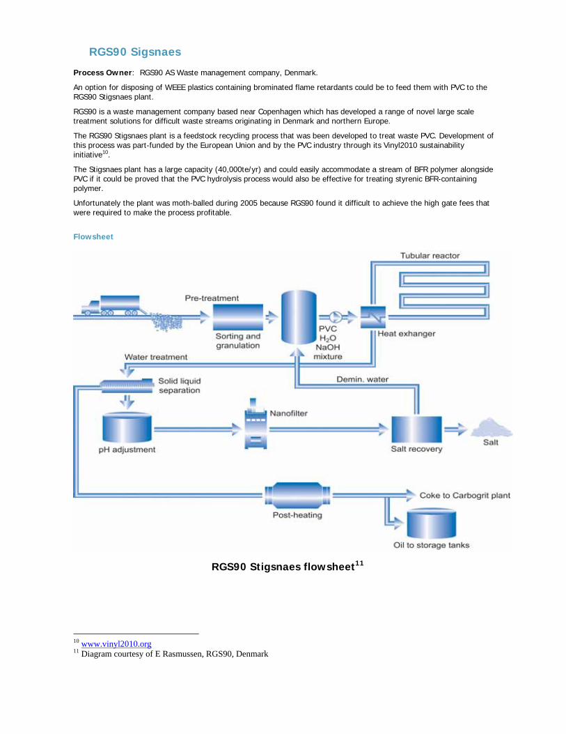
RGS90 Sigsnaes Process Owner: RGS90 AS Waste management company, Denmark.
An option for disposing of WEEE plastics containing brominated flame retardants could be to feed them with PVC to the RGS90 Stigsnaes plant.
RGS90 is a waste management company based near Copenhagen which has developed a range of novel large scale treatment solutions for difficult waste streams originating in Denmark and northern Europe.
The RGS90 Stigsnaes plant is a feedstock recycling process that was been developed to treat waste PVC. Development of this process was part-funded by the European Union and by the PVC industry through its Vinyl2010 sustainability initiative10.
The Stigsnaes plant has a large capacity (40,000te/yr) and could easily accommodate a stream of BFR polymer alongside PVC if it could be proved that the PVC hydrolysis process would also be effective for treating styrenic BFR-containing polymer.
Unfortunately the plant was moth-balled during 2005 because RGS90 found it difficult to achieve the high gate fees that were required to make the process profitable.
Flowsheet
RGS90 Stigsnaes flowsheet11
10 www.vinyl2010.org 11 Diagram courtesy of E Rasmussen, RGS90, Denmark
Process description
The Stigsnaes process is a new process, with the first commercial plant built recently in Denmark. The plant has been developed to treat PVC although we have been informed that the process can also treat BFR containing polymers.
Mixed plastic waste is shredded and fed to a heated mixing vessel where it is mixed with caustic soda solution to form a suspension. The mixture is then pumped through a heat exchanger into a pipe hydrolyser where the bromine and chlorine-containing plastics hydrolyse to sodium bromide, sodium chloride and denatured plastics. The operating plant is reported to have the equivalent of 6km of pipe in the hydrolyser with the hydrolyser operating at temperatures up to 260oC and pressures of 100bar.
After hydrolysis, the substance is divided into a liquid fraction and a dry fraction. The dry part consists of denatured plastic waste, from which the bromine content has been removed. This is filtered, discharged and sent for further treatment in a pyrolyser. The wet part consists mainly of sodium bromide salt, some of the phthalates and the heavy metals. These are separated by a nano filtration process to produce clean sodium bromide, which is evaporated and crystallized. The remaining unwanted materials from the nano filtration step are also fed to the pyrolysis process.
The RSG90 process works in conjunction with the nearby Carbogrit process that takes sewage sludge and coke to produce an expendable shot blasting media. Excess heat from the Carbogrit process is used to heat the Stigsnaes process to help accomplish the pyrolysis step.
The dry part now undergoes the process of pyrolysis, where it is heated and decomposes into oil and coke. All the phthalates in the BFR polymer end up in the pyrolysis furnace and are converted to oil. All the heavy metals end up in the coke fraction and are purified by the Carbogrit process.
The coke produced from the waste replaces new coke in the Carbogrit process and lime and minerals in the coke fraction become part of the Carbogrit end product. A fraction of the oil which is produced is used as fuel for the pyrolyser and the remaining oil is sent to a conventional crude oil refinery for further processing mixed with normal crude oil.
Effluents Produced
Water Effluent
De-mineralised water. This is bled from the de-mineralised water recycle stream.
Vapour effluent.
Combustion gases from the pyrolyser are passed to an air pollution control system which reduces emissions below Danish statutory limits.
Solids
Filter residue which consists of inerts and metals. The metals are recovered and sold, and the inerts are used in the Carbogrit process.
Business model RGS90 does not disclose its detailed operating costs. However it has disclosed enough information to this project (under non-disclosure agreement) to allow Axion to make an evaluation of the likely variation in RGS90’s gate fee in the event that processing of styrenic polymers is technically feasible using the RGS90 process.
Costs incurred for BFR polymer waste arising in the UK would include transportation costs in transporting the waste to Denmark and the plant gate fee.
Compared to the hydrolysis of PVC, BFR polymers require far less sodium hydroxide solution therefore the raw material cost should be less when processing BFR polymers. Currently the gate fee for PVC fed to the plant stands at £120/te.
As BFR polymer requires less sodium hydroxide than PVC and will also produce more crude oil from the polymer fraction the gate fee required for BFR feed so that the plant maintains its existing profit levels could be as low as £42/te.
Transport of waste polymer from UK to Denmark would add at least a further £50/te, leading to a total processing cost of just under £100/te. The business models for the other BFR treatment processes reviewed in this study assume a gate fee of £35/te.
There would be no additional capital costs associated with the process if polymer waste could be processed alongside PVC in the existing Stigsnaes plant in Denmark.
Recovery of the capital cost of the Stigsnaes plant is embodied in the gate fee currently charged by RGS90.
Because the Stigsnaes plant is a conversion of an existing plant originally built for another purpose and has also received substantial grant support a new plant built in the UK would be considerably more expensive
Discussion The RGS90 process has not been proven as an option for debromination of BFR polymers in practical trials. However discussions with RGS90 regarding their extensive experience of pyrolysis debromination of WEEE polymers and their experience of sodium hydroxide hydrolysis of PVC indicate that if a stream of WEEE polymer is processed alongside PVC in the Stigsnaes plant there is a good chance that the process will extract the bulk of the bromine and produce a crude oil with potential for use as a chemical feedstock. The outline business modelling conducted in collaboration with RGS90 indicates that the cost of processing this material alongside PVC should be lower for BFR polymer than for PVC. However this calculation includes assumptions regarding the crude oil quality that have not yet been proven. Brominated flame retardants will be considerably more difficult to hydrolyse than PVC. There is a good chance that significant quantities of bromine will remain in the crude oil product. This could devalue the whole crude oil stream from the process and greatly reduce the financial viability of this process route. The only way to prove the technical feasibility is to run a bulk trial with WEEE polymer in collaboration with RGS90. At present the Stigsnaes plant is moth-balled. For this reason no further work on this disposal option was proposed for Phase 3 of this project. The projected cost of about £100/te to transport BFR polymer waste from the UK to Denmark and then process it in the Stigsnaes plant at a reduced gate fee compared to PVC is not competitive with the projected commercial performance of the Creasolv and Centrevap process options. Both of these are projected to generate a profit at a gate fee of £45/te.

Appendix 4 – Phase 2 development of Creasolv and Centrevap process designs
This section presents the initial process designs for the Creasolv and Centrevap process options that were developed and evaluated during Phase 2. It includes details of the early process trials that were conducted.
Both process designs were further developed considerably during Phase 3 of the project. The final process designs and the final commercial and environmental evaluations of the optimised processes are presented in sections Error! Reference source not found. and Error! Reference source not found. of the main report.
Creasolv Process developer: Fraunhofer IVV Freising, Germany
Status at end of Phase 2: Technical scale development rig Dr Andreas Maeurer and his team at Fraunhofer IVV in Freising have spent several years developing this solvent separation process for WEEE polymers. The process concept is patented and there is a related company which plans to market the proprietary ‘Creasolv’ solvent mixture as a consumable.
A technical scale pilot facility is available at Freising for the dissolution, filtration, BFR-extraction and polymer-precipitation parts of the process while other aspects (solvent cycling, polymer drying and compounding at technical scale) have been tested at other facilities in Europe.
Creasolv process – Flowsheet – Phase 2
Filter
residue
Polymerchips 15 - 20mm
residue
Storage
to treatment
Solvent A
Residues todosposal
Pump
Cooler
Vac Pump
Vacuumevaporator
Polymer Solution
recycledSolvent A
FilterBatchdissolvers
CreaSolv Process – Simplified Flowsheet for dissolution and primary filtration
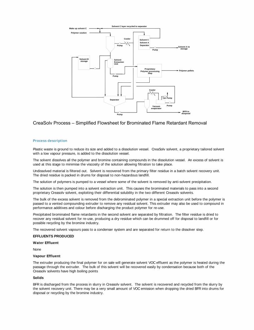
Make up solvent C
Polymer soution
Solvent C layer recycled to separator
Solvent A tostorage
Solvent Extraction
Polymer pellets
BFR todosposal
Separator
Solvent Bstorage
Pump
Pump
Pump
Pump
Cooler Solvent CSolvent ASeparator
Pump
Cooler
Vac Pump
Vacuumevaporator
Unit
Polymer processingProprietary
Step
CreaSolv Process – Simplified Flowsheet for Brominated Flame Retardant Removal
Process description Plastic waste is ground to reduce its size and added to a dissolution vessel. CreaSolv solvent, a proprietary tailored solvent with a low vapour pressure, is added to the dissolution vessel.
The solvent dissolves all the polymer and bromine containing compounds in the dissolution vessel. An excess of solvent is used at this stage to minimise the viscosity of the solution allowing filtration to take place.
Undissolved material is filtered out. Solvent is recovered from the primary filter residue in a batch solvent recovery unit. The dried residue is packed in drums for disposal to non-hazardous landfill.
The solution of polymers is pumped to a vessel where some of the solvent is removed by anti-solvent precipitation.
The solution is then pumped into a solvent extraction unit. This causes the brominated materials to pass into a second proprietary Creasolv solvent, exploiting their differential solubility in the two different Creasolv solvents.
The bulk of the excess solvent is removed from the debrominated polymer in a special extraction unit before the polymer is passed to a vented compounding extruder to remove any residual solvent. This extruder may also be used to compound in performance additives and colour before discharging the product polymer for re-use.
Precipitated brominated flame retardants in the second solvent are separated by filtration. The filter residue is dried to recover any residual solvent for re-use, producing a dry residue which can be drummed off for disposal to landfill or for possible recycling by the bromine industry.
The recovered solvent vapours pass to a condenser system and are separated for return to the dissolver step.
EFFLUENTS PRODUCED
Water Effluent
None
Vapour Effluent
The extruder producing the final polymer for on sale will generate solvent VOC effluent as the polymer is heated during the passage through the extruder. The bulk of this solvent will be recovered easily by condensation because both of the Creasolv solvents have high boiling points
Solids
BFR is discharged from the process in slurry in Creasolv solvent. The solvent is recovered and recycled from the slurry by the solvent recovery unit. There may be a very small amount of VOC emission when dropping the dried BFR into drums for disposal or recycling by the bromine industry.
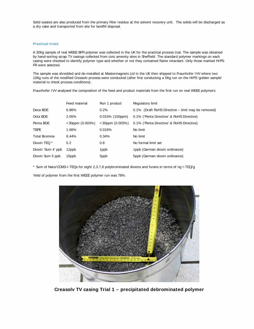
Solid wastes are also produced from the primary filter residue at the solvent recovery unit. The solids will be discharged as a dry cake and transported from site for landfill disposal.
Practical trials A 30Kg sample of real WEEE BFR polymer was collected in the UK for the practical process trial. The sample was obtained by hand-sorting scrap TV casings collected from civic amenity sites in Sheffield. The standard polymer markings on each casing were checked to identify polymer type and whether or not they contained flame retardant. Only those marked HIPS-FR were selected. The sample was shredded and de-metalled at Mastermagnets Ltd in the UK then shipped to Fraunhofer IVV where two 10Kg runs of the modified Creasolv process were conducted (after first conducting a 5Kg run on the HIPS ‘golden sample’ material to check process conditions). Fraunhofer IVV analysed the composition of the feed and product materials from the first run on real WEEE polymers: Feed material Run 1 product Regulatory limit
Deca BDE 6.86% 0.2% 0.1% (Draft RoHS Directive – limit may be removed)
Octa BDE 2.05% 0.015% (150ppm) 0.1% (‘Penta Directive’ & RoHS Directive)
Penta BDE <30ppm (0.003%) <30ppm (0.003%) 0.1% (‘Penta Directive’ & RoHS Directive)
TBPE 1.66% 0.016% No limit
Total Bromine 8.44% 0.34% No limit
Dioxin TEQ * 5.2 0.8 No formal limit set
Dioxin ‘Sum 4’ ppb 12ppb 1ppb 1ppb (German dioxin ordinance)
Dioxin Sum 5 ppb 15ppb 5ppb 5ppb (German dioxin ordinance)
* Sum of Nato/CCMS-I-TEQs for eight 2,3,7,8 polybrominated dioxins and furans in terms of ng I-TEQ/g Yield of polymer from the first WEEE polymer run was 78%.
Creasolv TV casing Trial 1 – precipitated debrominated polymer
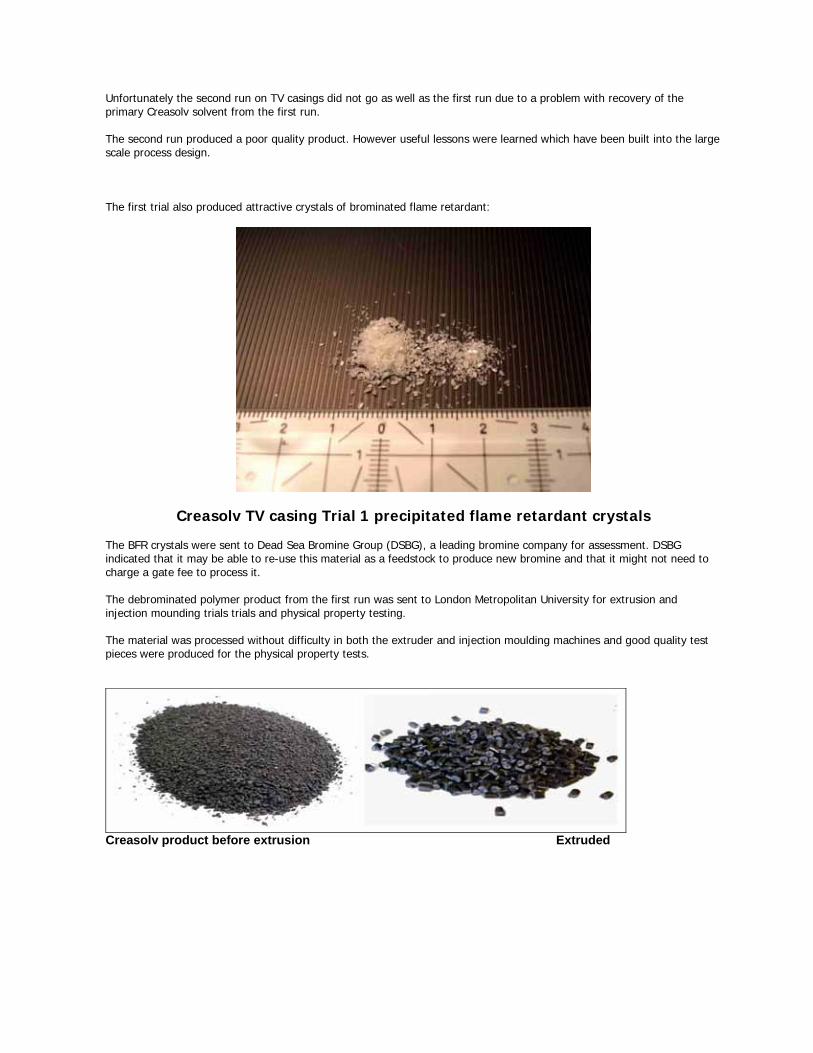
Unfortunately the second run on TV casings did not go as well as the first run due to a problem with recovery of the primary Creasolv solvent from the first run. The second run produced a poor quality product. However useful lessons were learned which have been built into the large scale process design. The first trial also produced attractive crystals of brominated flame retardant:
Creasolv TV casing Trial 1 precipitated flame retardant crystals The BFR crystals were sent to Dead Sea Bromine Group (DSBG), a leading bromine company for assessment. DSBG indicated that it may be able to re-use this material as a feedstock to produce new bromine and that it might not need to charge a gate fee to process it. The debrominated polymer product from the first run was sent to London Metropolitan University for extrusion and injection mounding trials trials and physical property testing. The material was processed without difficulty in both the extruder and injection moulding machines and good quality test pieces were produced for the physical property tests.
Creasolv product before extrusion Extruded
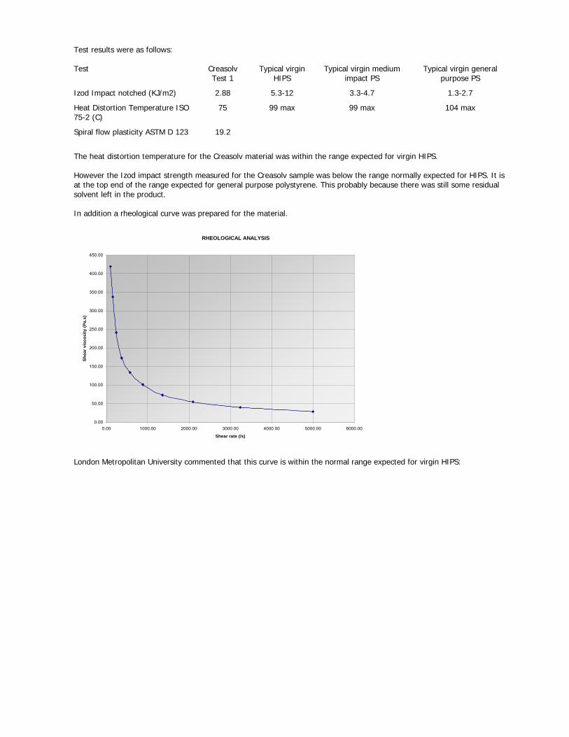
Test results were as follows: Test Creasolv
Test 1 Typical virgin
HIPS Typical virgin medium
impact PS Typical virgin general
purpose PS
Izod Impact notched (KJ/m2) 2.88 5.3-12 3.3-4.7 1.3-2.7
Heat Distortion Temperature ISO 75-2 (C)
75 99 max 99 max 104 max
Spiral flow plasticity ASTM D 123 19.2
The heat distortion temperature for the Creasolv material was within the range expected for virgin HIPS. However the Izod impact strength measured for the Creasolv sample was below the range normally expected for HIPS. It is at the top end of the range expected for general purpose polystyrene. This probably because there was still some residual solvent left in the product. In addition a rheological curve was prepared for the material.
RHEOLOGICAL ANALYSIS
0.00
50.00
100.00
150.00
200.00
250.00
300.00
350.00
400.00
450.00
0.00 1000.00 2000.00 3000.00 4000.00 5000.00 6000.00
Shear rate (/s)
Shea
r vis
cosi
ty (P
a.s)
London Metropolitan University commented that this curve is within the normal range expected for virgin HIPS:
Centrevap Process Developer Axion for WRAP
Status at end of Phase 2: Part of process tested at lab scale, evaporation step used at industrial scale for new polymers
The Centrevap process design was developed in the course of this project as a result of discussions between Axion and other project participants and observation of the results of other process trials conducted for the project. Similar process ideas have been patented previously in the US but differ in detail to the concept proposed here12.
Basis for the process design
It was observed there is a difference in solubility between WEEE polymers and the additives they contain and that this could be exploited to remove the insoluble additives.
Several different solvents can be used to dissolve the styrenic polymers found in WEEE. Some of these solvents do not dissolve some of the brominated flame retardants, particularly decabromodiphenyl ether.
Data obtained from product data sheets and research carried out for this project by Nottingham University indicates the following approximate solubilities for BFRs of interest to this project:
Solubilities g/100g solvent at 20C
Solvent Penta BDE Octa BDE Deca BDE TBBA TBPE Antimony trioxide
Methyl Ethyl Ketone C 16 <0.1 168 <0.1 <0.1
Toluene C 7 0.2 6 0.3 <0.1
Tetrahydrofuran C 70-80 C 0.5-1 <0.1
Dichloromethane C 12 0.1 27 1.3 <0.1
Methanol C 0.3 <0.1 80 <0.1 <0.1
C= Complete solubility
The table above indicates that Deca BDE, TBPE and antimony trioxide have low solubility in methyl ethyl ketone, toluene, tetrahydrofuran and dichloromethane at close to ambient temperature
TBBA also has relatively low solubility in toluene at ambient temperature but is fully or partly soluble in MEK, THF and dichloromethane.
Nottingham University also conducted qualitative tests of the solubility of ABS, HIPS and ABS/PC in a range of solvents for this project:
Solvent HIPS ABS ABS/PC
Methyl Ethyl Ketone
Dissolved rapidly to slightly milky solution
Dissolved rapidly to milky solution
Polymer looked degraded, expanded and cracked. Some colour from polymer seen in solution
Toluene Dissolved rapidly Completely insoluble. Polymer swelled slightly and slight colour change
Polymer insoluble. Looked degraded, expanded and cracked. Some colour from polymer seen in solution
Tetrahydrofuran Dissolved rapidly Dissolved rapidly Dissolved rapidly
Dichloromethane Dissolved rapidly Dissolved rapidly Dissolved rapidly
Dimethyl formamide
Dissolved rapidly to slightly milky solution
Dissolved rapidly to slightly milky solution
Dissolved rapidly to milky solution
Chloroform Dissolved rapidly Dissolved rapidly Dissolved rapidly
12 US Patent 5,824,709, Oct 1998, ‘Method for recycling waste plastic material containing styrene polymer’ Motoshi Suka
Solvent HIPS ABS ABS/PC
Diethyl ether
Insoluble but polymer appeared to become jelly-like with loss of shape
Completely insoluble. Polymer swelled and turned pale in colour
Completely insoluble. Polymer swelled and turned pale in colour
Methanol Completely insoluble, no changes observed
Completely insoluble. Swelled slightly and turned pale
Completely insoluble, no changes observed
Hexane Completely insoluble. Polymer swelled slightly and slight colour change
Completely insoluble. Slight colour change
Completely insoluble, no changes observed
Acetonitrile Completely insoluble. Polymer swelled slightly and colour turned slightly more vivid
Polymer dissolved forming a milky solution
Polymer looked degraded, expanded and cracked. Some colour from polymer seen in solution
Three different behaviours were observed according to the solubility ability of the solvent. These are:
• Anti-solvent (methanol, hexane)
• Plasticizer (diethyl ether)
• Solvent (chlorinated solvents, methyl ethyl ketone, THF, DMF, toluene)
In the cases where the polymer dissolved a more or less turbid solution was always formed. That could probably be explained by the presence of a small fraction of very long polymer chains remaining out of solution.
Unfortunately Penta BDE is completely soluble in all of these solvents and Octa BDE is partly soluble. This means that it will not be possible to use this process option to extract penta and octa BDE using conventional solvents.
However tests conducted for this project indicate that the amounts of these materials, particularly penta BDE, present in real WEEE polymers is rather small. Further trials must be conducted to establish the likely average concentration of Penta and Octa BDE in typical WEEE polymers of the type to be treated by this process.
If the concentration of Octa and Penta BDE is not too high then the process should still have commercial potential as a method for separating not just Deca BDE but also antimony trioxide and any other fillers and additives which are not soluble in the chosen solvent.
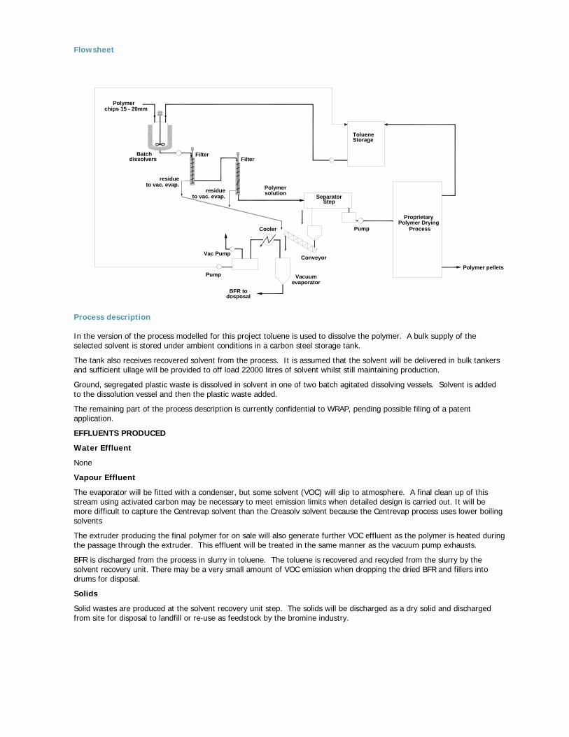
Flowsheet
Conveyor
Pump
SeparatorPolymersolution
BFR todosposal
Pump
Cooler
Vac Pump
Vacuumevaporator
Polymer pellets
FilterBatchdissolvers Filter
residue
Polymerchips 15 - 20mm
residue
StorageToluene
to vac. evap.
to vac. evap.
ProprietaryPolymer Drying
Process
Step
Process description In the version of the process modelled for this project toluene is used to dissolve the polymer. A bulk supply of the selected solvent is stored under ambient conditions in a carbon steel storage tank.
The tank also receives recovered solvent from the process. It is assumed that the solvent will be delivered in bulk tankers and sufficient ullage will be provided to off load 22000 litres of solvent whilst still maintaining production.
Ground, segregated plastic waste is dissolved in solvent in one of two batch agitated dissolving vessels. Solvent is added to the dissolution vessel and then the plastic waste added.
The remaining part of the process description is currently confidential to WRAP, pending possible filing of a patent application.
EFFLUENTS PRODUCED
Water Effluent
None
Vapour Effluent
The evaporator will be fitted with a condenser, but some solvent (VOC) will slip to atmosphere. A final clean up of this stream using activated carbon may be necessary to meet emission limits when detailed design is carried out. It will be more difficult to capture the Centrevap solvent than the Creasolv solvent because the Centrevap process uses lower boiling solvents
The extruder producing the final polymer for on sale will also generate further VOC effluent as the polymer is heated during the passage through the extruder. This effluent will be treated in the same manner as the vacuum pump exhausts.
BFR is discharged from the process in slurry in toluene. The toluene is recovered and recycled from the slurry by the solvent recovery unit. There may be a very small amount of VOC emission when dropping the dried BFR and fillers into drums for disposal.
Solids
Solid wastes are produced at the solvent recovery unit step. The solids will be discharged as a dry solid and discharged from site for disposal to landfill or re-use as feedstock by the bromine industry.

Appendix 5 – Environmental Impact Assessment detail
Appendix 5 is split into six sections:
A. White Young Green ISO14040 Qualitative and Quantitative Environmental Impact Assessment Report B. Explanation of QWERTY analysis C. QWERTY Analysis method used for this project D. Detailed results of QWERTY analysis E. White Young Green update report for Phase 3 F. Huisman update of QWERTY analysis for Phase 3

Appendix 5A - White Young Green initial Environmental Impact Analysis
thinking beyond construction
Life cycle assessment Study: SUMMARY REPORT Selected Treatment Processes for WEEE Plastics Containing Brominated Flame Retardants for Axion Recycling On behalf of Waste Resources Action Programme (WRAP) Project Ref: E4833 August 2005
Reference: Life Cycle Assessment Summary Report – August 2005
Issue Prepared by Checked by Verified by 1 August 2005
EMILY FREER PHIL STUDDS GEOFF RICHARDSON Environmental Consultant Associate Regional Director
File Ref: N:\Projects\E4501-E5000\E004833\reports White Young Green Environmental Limited, Arndale Court, Headingley, Leeds. LS6 2UJ.
Telephone: 0113 278 7111 Facsimile: 0113 275 0623 E-Mail: [email protected]
Life cycle assessment Study: SUMMARY REPORT Selected Treatment Processes for WEEE Plastics Containing Brominated Flame Retardants for Axion Recycling On behalf of Waste Resources Action Programme (WRAP) Project Ref: E4833 August 2005
WHITE YOUNG GREEN ENVIRONMENTAL
LCA of Process Options for BFR WEEE Plastics 63 August 2005 Project No. E4833 Issue 1
TABLE OF CONTENTS
Page No. 1.0 Background 1 2.0 Aims 1 3.0 Introduction 2 3.1 Waste Electrical and Electronic Directive (WEEE) 2 3.2 What are Brominated Flame Retardants? 3 3.3 LCA Studies 4
3.3.1 What does an LCA involve? 4 3.3.2 Defining the goal and scope of the study 4 3.3.3 Collecting Inventory Data 4 3.3.4 Impact Assessment 5 3.3.5 Interpreting the Results 6
4.0 Goals and Scope of the Study 7
4.1 Goals of the Study 7 4.2 Scope of the Study 7
4.2.1 The Functional Unit 9 4.2.2 System Boundaries 9
4.2.3 Data quality 9 4.2.4 Critical Review 10
5.0 Collecting Inventory Data 11 6.0 Impact Assessment 12
6.1 Impact Assessment Categories 12 6.2 Qualitative Assessment 15 6.2.1 Introduction 15 6.2.2 Assessment Matrix 15 6.2.3 Environmental Impact Categorises 16
6.2.4 Results from Qualitative Assessment 17 6.3 Quantitative Assessment 18 6.3.1 Environmental Impact categories 18 6.3.2 Results from Quantitative Assessment - 18 Environmental Indicators 6.3.3 Environmental Toxicology – Qualitative Assessment 20 6.3.4 Results from Quantitative Assessment – 23 Overall Environmental Impacts
7.0 Summary and Conclusions 26 8.0 Limitations of the Study 27 9.0 References 28 10.0 Glossary 30
WHITE YOUNG GREEN ENVIRONMENTAL
LCA of Process Options for BFR WEEE Plastics 64 August 2005 Project No. E4833 Issue 1
APPENDICES Appendix A Report Conditions 31 Appendix B Energy Conversion Factors 33 Appendix C Assumptions 35 Appendix D Qualitative Assessment – Scoring process 40
LCA of Process Options for BFR WEEE Plastics 65 August 2005 Project No. E4833 Issue 1
Life-cycle Assessment of Waste Treatment Options for Waste Electrical and
Electronic Plastic containing Brominated Flame Retardant Compounds 1.0 Background The WEEE (Waste Electronic and Electrical Equipment) Directive requires the separation of plastics containing brominated flame retardants (BFR) prior to energy recovery, recycling or disposal. However, currently BFR’s are considered to represent an obstacle to the closed-loop recycling of these polymers due to the fact that presently there are no commercially viable processes available to extract BFR from WEEE plastics. Also, few options exist which separate polymers containing BFR’s from those that do not. White Young Green Environmental (WYGE) were commissioned by Axion Recycling to undertake a Life Cycle Assessment (LCA) study of designated processing options for plastics containing brominated flame retardants. This forms part of the Phase 2 project: ‘Develop a process to separate brominated flame retardants from WEEE polymers’ funded by the Waste and Resources Action Programme (WRAP).
2.0 Aims The aim of the Waste Recycling Action Programme (WRAP) funded study was to investigate the suitability of commercially viable techniques of extracting BFR’s from WEEE polymers in order to create better opportunities for the closed–loop recycling of WEEE polymers back into new electronic and electrical equipment. An environmental assessment is a systematic and phase-based approach used to evaluate and assess the environmental impacts of specific processes or products and enable realistic comparisons of environmental performance to be made between them. This can aid decision makers select those products or processes that produce the least impact on the environment and/or identify where environmental improvements can be made.
LCA of Process Options for BFR WEEE Plastics 66 August 2005 Project No. E4833 Issue 1
3.0 Introduction Evaluating commercial and economical factors associated with innovative waste treatment options does not provide a holistic view of the viability of such processes as these maybe distorted and restricted by statutory legislative requirements, political factors, short-term taxation policies and economic instruments which favour particular disposal routes or process options. The environmental performance of waste management options is typically independent of such economic and political factors and is of primary importance in determining which process offers the best overall environmental benefits. Environmental impact assessments assess the environmental aspects and potential impacts of a product or process on the environment and considers the trade-off’s between media that may occur between different processes. This may encompass the ‘life-cycle’ of the product or process, which includes all processes from cradle-to-grave, including intermediate processes that are often excluded from other analyses, such as transportation, use of packaging etc. This is achieved by compiling an inventory of input and outputs through a defined system, evaluating the potential environmental impacts of through-put material and relating potential impacts to inventory analysis and assessment. 3.1 Waste Electrical and Electronic Directive (WEEE) 2002/96/EC The WEEE Directive (2002/96/EC) introduces collection, recycling and recovery targets for all waste electrical and electronic products, the first of which is to be achieved by December 2006. These include minimum recycling targets of certain categorises of WEEE of 50 - 80% and minimum recovery targets of 70 – 80% and compulsory household collection targets of 4kg per householder to be achieved by the end of 2006. New targets are to be established by the end of 2008. Additional requirements of the Directive include;
• Compulsory producer responsibility funded collection and take-back schemes; private householders will be able to return their WEEE to collection facilities free of charge;
• The cost of ‘orphaned’ waste will be funded between current market producers, based proportionately on market share, with guarantees to be made by producers to guard against costs arising from this waste;
• Measures to be taken to reduce WEEE disposal as municipal waste by householders; Annex 2 of the Directive also requires the separate treatment of certain components recovered from WEEE including; • Liquid crystal displays (LCD) over 150 sq.cm • Mercury switches • Asbestos • Polymers containing BFR’s • Capacitors containing PCB’s • Cathode ray tubes and gas discharge lamps • Batteries and toner cartridges • CFC’s Alongside the WEEE Directive, a daughter Directive, The Restriction of the Use of Certain Hazardous Substances in Electrical and Electronic Equipment (RoHS) (02/95/EC) was also adopted.
LCA of Process Options for BFR WEEE Plastics 67 August 2005 Project No. E4833 Issue 1
This Directive requires that from 1st July 2006, new E & E equipment placed onto the market does not contain; • Lead • Mercury • Cadmium • Hexavalent chromium • Polybrominated biphenyls (PBB) • Polybrominated diphenylethers (PBDE) 3.2 What are Brominated Flame Retardants? These are compounds containing bromine which when added to materials such as plastics inhibit or suppress the ability of the material to burn by either interfering with the heating, decomposition, ignition or flame dispersal process. They are widely found in electronic and electrical equipment, furniture and office equipment, paints and textiles. There are over 75 commercial brominated flame retardants on the market, of which there are four main groups; Polybrominated biphenyls (PBB’s), Hexabromocyclododecane (HBCD), Polybrominated Diphenyl ethers (PBDE’s) (of which Deca-BDE, Penta-DBE and Octa-BDE are the most common) and tetrabromobisphenol-A (TBBPA). HBCD is largely associated with textile and building applications and is not typically used in electrical and electronic applications; only one PBB compound, decabromobiphenyl (DeBB) has been used commercially and while production of this compound has now ceased, PBB’s will continue to feature in the electrical and electronic plastic waste stream. PBDE’s are a group of aromatic brominated compounds which can be divided into two groups, depending on their bromine content. The lower brominated compounds include tetra-BDE, Penta-PDE and hexa-BDE with the higher brominated compounds including Octa-BDE, Nona-BDE and Deca-BDE. Deca-BDE is the most commercial BDE, however the manufacture and use of many of the lower brominated BDE’s, including Penta-BDE and Octa-BDE have now been banned in Europe due the toxicological effects of these compounds. There are concerns that Deca-BDE can potentially degrade into lower brominated PBDE’s are largely used in the manufacture of plastic housing for small office equipment and for TV and monitor housings. TBBPA can be found as an additive or reactive flame retardant in different plastic polymers. It has replaced many of the lower PBDE’s in computer and TV housings as these compounds have been banned and is also widely used in printed circuit boards and automotive parts. BFR’s may be found as reactive or additive compounds in plastic polymers. How these compounds have been added to the plastic polymers is important in being able to evaluate how the flame retardants will behave during the life-cycle of the product or during disposal processes. Reactive or ‘back-bone’ flame retardants are chemically in-built into the plastic polymers in which they are found. This means that they will not bleed-out of the polymer and vaporise over time. The most common reactive brominated flame retardants are TBBPA, TBPE and brominated styrene.
LCA of Process Options for BFR WEEE Plastics 68 August 2005 Project No. E4833 Issue 1
Additive or ‘matrix’ flame retardants however, are incorporated into the plastic polymer either prior to, during or after polymerisation. As they are not chemically bound into the structure of the polymer they have the potential to bleed-out of the polymer over time and vaporise. The performance of these flame retardants therefore may decrease over time as the concentrations of the compounds are lost to the atmosphere. The most wide-spread additive brominated flame retardants are PBDE’s, TBBPA and HBCD. 3.3 LCA Studies Public concerns over the impact that industries and businesses have on the environment have continued to increase as issues such as resource depletion and environmental degradation have been repeated brought to the front of discussions on sustainability, deforestation and global warming. As a result, many businesses have started to assess how their activities affect the environment in order to provide the ‘greener’ products demanded by consumers, which go beyond traditional ‘command and control’ legislative regulation. One tool for assessing the environmental impacts of products, services or industries is to consider the full environmental impact of these material and activities over their full life-cycle. Life-cycle assessments (LCA’s) are a ‘cradle-to-grave’ approach for assessing industrial systems, encompassing the environmental impacts of extracting and processing raw materials, through to product manufacture, use and final disposal (landfill, incineration, recycling etc.) This can include activities and impacts such as transportation, packaging and disposal options which may not be considered in other analyses. 3.1.1 What does an LCA involve? A life cycle assessment study is a systematic and phase-based approach comprising of four core processes; goal definition, collection of inventory data, impact assessment and interpretation. 3.1.2 Defining the goal and scope of the study; This encompasses detailing the purpose and application of the study, the process, product or service to be studied and any alternatives, if relevant, and the audience to which the study is targeted. The system boundary of the study and the ‘functional unit’ should also be defined. The system boundary details the limitation of the study and identifies those activities on which data will be collected. This includes defining the processes and operations to be included, inputs and outputs of the system. System boundaries may be geographical, environmental (i.e. distinguish between the technosphere and biosphere for example) or life-cycle based. The functional unit characterises the scale of comparison for two or more processes or products and is the unit to which all data collected in the inventory will be linked. Information should also be provided relating to the quality of data used throughout the study.
3.1.3 Collecting Inventory Data This involves quantifying all the inputs and outputs of a product, service or process by compiling an inventory of relevant energy and material inputs and associated environmental outputs. Data should be collected from all single processes in the life-cycle, but can be quantitative or qualitative in nature. While quantitative data is important to compare products or processes, descriptive qualitative data can be used for environmental aspects or processes in the life cycle that can not be quantified. It is important to consider allocation procedures for processes and systems that involve multiple products, i.e. petroleum refinery; materials, energy flows and releases should be allocated appropriately, stated and justified.
LCA of Process Options for BFR WEEE Plastics 69 August 2005 Project No. E4833 Issue 1
With regards to energy flows, fuels, electricity generation sources, energy efficiency conversion factors, inputs and outputs should be considered and detailed. Inventory data should also undergo validation during the study to ensure and improve data quality. Comparative data should be reported to an appropriate reference flow and where delivered in different formats, converted to the reporting standard reference flow. This should be defined and described where appropriate.
3.1.4 Impact Assessment This involves evaluating the potential impact that these inputs and outputs have on the environment and human health. This process is considered to comprise of; category definition, classification, characterisation, normalisation and valuation or weighting. The International Organisation of Standardisation’s (ISO) standard for conducting impact assessments, titled ISO 14042, Life Cycle Impact Assessment (ISO 1998), states that the first three stages category definition, classification and characterisation are mandatory steps in a life cycle assessment. Normalisation and weighting exercises are optional dependant on the goal and scope of the study.
• Category Definition
Defining the impact categories to be considered as part of the overall LCA follows decisions made in defining the goal and scope of the assessment. Impact categories are defined as the consequences caused by the input and output streams of a process on human health, plants and animals, or the future availability of natural resources. These consequences may include harm to human health, such as the release or formation of cancer-causing agents or those causing sterility, environmental impacts, such as global warming or acid rain and ecological toxicity.
Impact categories may include; global warming, acidification, eutrophication, stratospheric ozone depletion, ecological (aquatic and terrestrial) toxicity, human toxicity, resource depletion, land use and photochemical oxidation potential.
• Classification
Classification aims to organize and assign inventory input-output data to impact categories. Where inventory data falls into one category, the procedure is straight forward, however, some data may fall into two or more categories and therefore the effects of this output is counted twice. While double counting is acceptable if the effects are independent of one another, double counting can not occur where the effects are dependant on each other. For example, nitrogen dioxide can effect both acidification and ground level ozone formation at time the same time and therefore the effects this output has on each categories can be counted. However, sulphur dioxide can either stay at ground level and effect human health or it can travel into the atmosphere and contribute to acidification, but it can not contribute to both. In such cases, it would be feasible to allocate a representative portion of the results from the assessment for this output to each category, i.e. 50%.
• Characterisation Characterisation involves aggregating input and out data within an impact category. This typically involves using ‘indicators’ or ‘equivalency factors’ to convert and combine data into representative indicators for impacts to enable different inventory outputs to be directly compared. At this stage the implicit assumption that ‘less is best’ is linked to important considerations such as potency and environmental persistence to enable the impacts of different quantities of compounds to be assessed on an equal scale.
LCA of Process Options for BFR WEEE Plastics 70 August 2005 Project No. E4833 Issue 1
For some environmental impact categories there is a consensus about the equivalency factors to be used in the estimation of total impact (i.e. global warming potential is measured to the reference compound, carbon dioxide, with standard potency factors applied to other compounds and to it and expressed in tones CO2/year equivalents.) For impact categories such as land use however, no consensus has yet been reached and variations in how this is expressed exist.
• Normalisation and weighting While characterization groups inventory outputs into different impact categories, it is not possible to directly compare the different impact categories themselves. Normalisation and weighting aim to rank or aggregate the results of different categories into an order of relative importance. This is not a technical, scientific or objective process as impact categories and different environmental impacts are not directly comparable. It is a process which assigns weights or relative values to the different impact categories based on their perceived importance or relevance; this should also reflect the goals of the study and stakeholder values.
3.1.5 Interpreting the Results This involves interpreting the results of the study, linking them to the objectives of the process, showing a clear understanding of the uncertainties and assumptions used to generate the results. The accuracy of the results must be verified and sufficient to support the purposes for performing the LCA as defined in the goals and scope of the survey. Study limitations should also be included; this may include a lack of spatial and temporal resolution, i.e. the size of river into which effluent is discharged; the effects will be greater in a small river than a large river and if all the effluent is released at once as opposed to small amounts over a longer period. Other limitations may include inventory speciation, where compounds are grouped together, i.e. VOC’s and metals; this is not sufficient information to accurately assess the environmental impact of these compounds and threshold limits; 5 tonnes of contamination does not necessarily imply that the environmental effects are 5-times greater than 1 tonne of contamination. LCA studies are useful tools as they encompass all process inputs and outputs which enables a realistic comparison of the environmental performance to be made between two or more products or processes encompassing all stages of the life cycle from raw material extract through the final disposal of the product. This can aid decision makers select those products or processes that produce the least impact on the environment and/or identify where environmental improvements can be made.
LCA of Process Options for BFR WEEE Plastics 71 August 2005 Project No. E4833 Issue 1
4.0 Goals and Scope of the Study 4.1 Goals of the Study The objectives of the study were to assess the potential environmental impacts of four new process options for recovering electrical and electronic (E & E) plastic waste containing BFRs against landfill and traditional recovery options. The traditional recovery options include incineration with energy recovery (no bromine recovery), mechanical recycling and feedstock recycling. Two of these new process options were high-lighted in the Interim Report published by Wrap in January 2005 titled ‘Develop a process to separate brominated flame retardants from WEEE polymers’ and included; Creasolv, and the Ionic Liquid processes. The other two additional processes detailed in the Interim Report were rejected from further analysis due to a lack of process data and perceived lack of commercial viability on conclusion of the report. However, two additional processes were introduced for the purpose of this study; namely the Centrifuge and Evaporation and the Filtration and Anti-solvent processes. The focus of the study was to compare the potential environmental impacts of recovering brominated flame retardant plastic waste using the identified waste treatment processes, from E & E sources, to those environmental impacts avoided by using the resulting recyclate to substitute other materials. This study follows the principles and methods of the ISO 14040 Standard Environmental Management – Life Cycle Assessment – Principles and Framework (1997a). 4.2 Scope of the Study The scope of the study considers the potential treatment options for waste plastics from E & E equipment. Small WEEE items such as mobile phones, MP3 players etc. were not considered in this project as alternative treatment methods, specifically the inclusions of these items into metal smelter furnaces was considered to be the most viable treatment method at present. The interim WRAP report issued in January 2005 stated that the process options considered would be more commercially viable if they can be applied to polymers which have already been sorted into polymer type and where non-BFR-containing polymers have been removed. Therefore, it has been presumed that WEEE dismantling and pre-sorting of WEEE plastics from brown and white E & E goods has taken place to produce a mix of plastic material that is dominated by the styrenic polymers HIBS (High Impact Polystyrene), ABS (Acrylonitrile Butadiene Styrene) and PC (Polycarbonate) in equal proportions. The main brominated flame retardants considered to be present in these polymers are: TBBPA (forming 7% in PC/ABS polymers and 5% in ABS polymers), Deca-BDE (forming 10% in HIPS polymers and 3% in ABS polymers), Octa-BDE (forming 5% in ABS polymers) and TBPE (forming 0.5% in ABS polymers). For the purpose of this study, it is assumed that the substituted materials were crude oil in the case of feedstock recycling, virgin HIPS, PC and ABS polymers in the case of high-grade recycling.
LCA of Process Options for BFR WEEE Plastics 72 August 2005 Project No. E4833 Issue 1
The waste treatment process option considered by this study included the following: a. Landfill – this is the reference system that is standard practice for WEEE plastics
currently in the UK. The time span of the landfill site is considered to be 100 years. WEEE plastic waste is co-landfilled with other non-hazardous waste and no secondary products or recovered materials are gained from landfilling.
b. Mechanical recycling with separated BFR WEEE plastics – treatment and recycling of Low-BFR polymers and non-BFR WEEE polymers; presumes that the styrenic polymers PS, HIPS and ABS have been extracted in the dismantling, and pre-sorting phase outside the scope of the study. Presumed output is high-grade recyclate products, capable of substituting virgin polymers.
c. Incineration (no energy recovery) – using reject BFR polymers resulting from a mechanical sorting process. This material has been presumed to be incinerated with Municipal Solid Waste (MSW); a ratio of 3:97 BFR polymers to MSW has been presumed.
d. Incineration with energy recovery – using reject BFR polymers resulting from mechanical sorting process. This material has been presumed to be incinerated with Municipal Solid Waste (MSW); a ratio of 3:97 BFR polymer to MSW has been presumed. Energy only is recovered from this process at a presumed conversion efficiency of 26%.
e. Feedstock recycling process RGS-90 – This process has been developed for the treatment of PVC plastic waste but may be applied to brominated plastic wastes. Plastic polymers are mixed with caustic soda, pump through a heat exchanger and hydrolyser. The plastics hydrolyse to sodium bromide and denatured plastics. The plastic mix is filtered and the plastic waste discharged for further treatment; pyrolysis into an oil for further refining.
f. Creasolv – ground plastic material is dissolved in the creasolv solvent, which is filtered and passed through a second solvent through which the BFR’s are extracted. The resulting solution is then passed through a solvent recovery process to produce a polymer that is suitable for re-use.
g. Ionic Liquids – This process uses a novel solvent which can be tailored to provide specific solvent properties. Plastic polymers are mixed with the ionic liquid into which the brominated compounds diffuse from the polymer matrix. The ionic liquid and solvent are processed and recycled.
h. Centrevap – This process uses solvents into which the plastic waste is dissolved at slightly elevated temperatures of 40°C – 60°C. The resulting slurry is then treated to remove the solid materials, including un-dissolved plastics, fillers and other additives, including un-dissolved BFR; these are collected and discharged as waste. The remaining slurry passes into a solvent recovery system to recycle the solvent and produce a pelletised clean polymer product.
i. Anti-solvent – This process uses a two solvents; the plastic waste is dissolved in one solvent at slightly elevated temperatures of 40°C – 60°C. The resulting slurry is then treated to remove the solid materials, including un-dissolved plastics, fillers and other additives, including un-dissolved BFR; these are collected and discharged as waste. A second solvent is then mixed with the polymer solution causing the polymer to precipitate; the solids are then removed using a centrifuge. The precipitated material is then melted and passed through a solvent recovery system prior to pelletisation of the material.
LCA of Process Options for BFR WEEE Plastics 73 August 2005 Project No. E4833 Issue 1
4.2.1 The Functional Unit The functional unit of this study refers to the processing (input) of 1429kg of WEEE plastic polymer pre-sorted into brominated flame retarded styrenic polymers. This unit was defined by the mass balance throughput data available on the new process options and has been applied to other treatment options. With reference to incineration technologies, it has been assumed that this mass of plastic waste must be combined with municipal solid waste at a ratio of 3:97; the weight of total material entering this system has been multiplied up accordingly. It has also been presumed that 29kg of the input material is inert contaminants and 10% of the weight of plastic is accounted for by brominated flame retardant species. In the case of mechanical recycling, it has been assumed that the functional unit is 1429kg of WEEE source plastics which have been pre-sorted to exclude brominated flame retardant styrenic polymers PS, HIPS and ABS; it has also been presumed that 29kg of the input material are inert contaminants. 4.2.2 System Boundaries
System boundaries were defined to incorporate the waste treatment options for separated E & E plastic waste; collection of this material originating from WEEE pre-sorting and dismantling plants is excluded as no study specific data was available and all transport related inputs and outputs would have been standardised for all process options. The defined system boundaries of this study can be seen in Figure 1. The process of generating waste electrical and electronic equipment, the dismantling and pre-treatment of WEEE and polymer sorting of WEEE plastics from disposal collection points is specifically excluded. It was also assumed that the environmental impacts of final product manufacture using virgin compounds or recyclate were equal; this was also excluded from the scope of the survey.
As the study was conducted with a view to providing an broad overview of the potential environmental impact and comparable environmental performance of the different waste treatment processes, only those main consumables into each system were considered, i.e. primary energy, plastic polymer, inerts, solvents, water while output emissions inventories were restricted to the main species characterized in energy emission inventories; carbon dioxide, carbon monoxide, nitrogen oxides (NOx), sulphur dioxide, Methane, non-methane Volatile Organic Hydrocarbons (NMVOC’s). Emissions to water have been specifically excluded.
4.2.3 Data quality Data available on the new recycling processes was obtained from practical studies and mass balance exercises undertaken by Axion Recycling. However, this information was only available at an aggregated level; only major material flows were detailed and no break down of energy consumption sources or measured emissions data was available. As such, realistic assumptions have been made where required; for example, solvent emissions during waste drum filling, and emission inventories for energy consumption have been derived from emission factors detailed in publicly available sources, such as NETCEN. Avoided emissions and energy data relating to the production of virgin polymers was taken from the Eco-profile studies undertaken by the APME (Association of Plastic Manufacturers in Europe) during the late 1990s for the styrenic polymers included within this study. This information, although dated, has also been used as a base for deriving avoided energy and emissions data for the production and extraction of crude oils with regards to feedstock recycling processes.
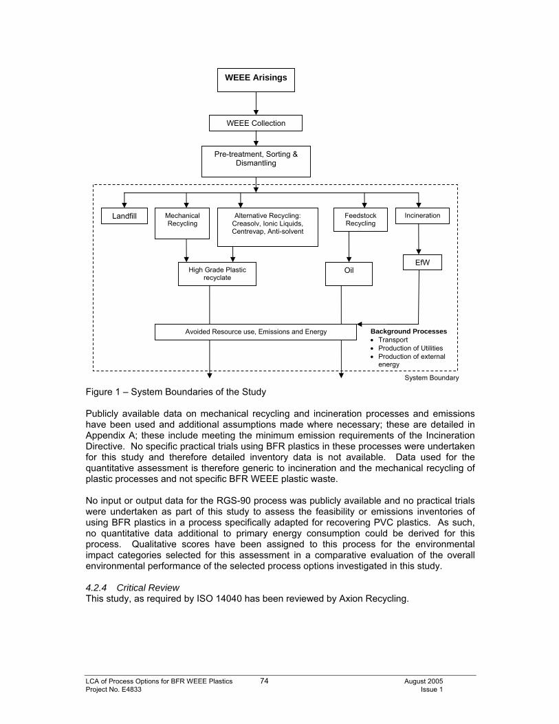
LCA of Process Options for BFR WEEE Plastics 74 August 2005 Project No. E4833 Issue 1
Figure 1 – System Boundaries of the Study Publicly available data on mechanical recycling and incineration processes and emissions have been used and additional assumptions made where necessary; these are detailed in Appendix A; these include meeting the minimum emission requirements of the Incineration Directive. No specific practical trials using BFR plastics in these processes were undertaken for this study and therefore detailed inventory data is not available. Data used for the quantitative assessment is therefore generic to incineration and the mechanical recycling of plastic processes and not specific BFR WEEE plastic waste. No input or output data for the RGS-90 process was publicly available and no practical trials were undertaken as part of this study to assess the feasibility or emissions inventories of using BFR plastics in a process specifically adapted for recovering PVC plastics. As such, no quantitative data additional to primary energy consumption could be derived for this process. Qualitative scores have been assigned to this process for the environmental impact categories selected for this assessment in a comparative evaluation of the overall environmental performance of the selected process options investigated in this study. 4.2.4 Critical Review This study, as required by ISO 14040 has been reviewed by Axion Recycling.
WEEE Arisings
Pre-treatment, Sorting & Dismantling
Landfill Mechanical Recycling
Incineration
WEEE Collection
EfW High Grade Plastic
recyclate Oil
Feedstock Recycling
System Boundary
Background Processes • Transport • Production of Utilities • Production of external
energy
Avoided Resource use, Emissions and Energy
Alternative Recycling: Creasolv, Ionic Liquids, Centrevap, Anti-solvent
LCA of Process Options for BFR WEEE Plastics 75 August 2005 Project No. E4833 Issue 1
5.0 Collecting Inventory Data The first stage of the assessment involved quantifying all the inputs and outputs of each process by compiling an inventory of relevant energy and material inputs and associated environmental outputs. This data can be quantitative or qualitative in nature. To this effect, a qualitative pre-assessment of environmental impacts of each of the process options was undertaken to identify the potential environmental performance of each process. This was then supported by a quantitative assessment, using selected key environmental indicators. Mass balance data provided from practical studies of waste treatment processes for BFR WEEE plastics has been used as a base for deriving more detailed inventory data where required. Assumptions have been made on the energy sources for these processes and emission inventories derived from nationally published UK data. Typically these have been sourced from NETCEN. All assumptions are detailed in Appendix C. Inventory inputs and outputs relating to the avoided impacts of using recyclate in place of virgin styrenic polymers and crude oil have been taken from the Eco-profiles of the respective polymers published by APME; these have been derived from data provided to the APME from working plants across Europe and relate to specific production years. These are reported as inputs/ outputs per kg of polymer produced. With regards to energy flows, fuels, electricity generation sources, energy efficiency conversion factors and emission factors, all these data are detailed in Appendix B and C. Allocation procedures for processes and systems that involve multiple products, i.e. petroleum refinery; materials, energy flows and releases have been considered and are detailed in Appendix B and C. This data has been used to produce a simplified LCA to identify the potential inputs and outputs of these processes with regards to BFR plastic waste recovery options. Specific practical study data has been used where available in relation to the new process options evaluated. However, no specific inventory data was available relating to the processing of BFR plastics in mechanical recycling process, the feedstock recycling process or incineration processes. Generic, publicly available data has been used where available and the assumptions made in using this information are detailed in Appendix B and C.
LCA of Process Options for BFR WEEE Plastics 76 August 2005 Project No. E4833 Issue 1
6.0 Impact Assessment 6.1 Impact Assessment Categories The following environmental impact categories were chosen and assessed for each waste treatment process; • Global Warming • Abiotic Resource Use • Environmental toxicity • Photo-oxidant formation Other environmental indicators were considered for inclusion in this study, however, time constraints restricted the use of some additional indicators, while the use of other indicators were considered to be less relevant to the goals of the study. These are detailed below. Global Warming Global warming of the ‘green-house effect’ is the process whereby the lower atmosphere is heated by incoming radiation by the presence of gases, which prevents the release of this radiation into the outer atmosphere. The consequence of this process is elevated global temperatures, which may result in regional climate changes and lead to melting of the polar ice-caps and elevation of sea levels, causing global climate change. The potential impact that greenhouse gases have on the environment is not only function of the volumes of gases released into the atmosphere, but also their ability to absorb or trap heat and their longevity in the environment. A co-efficient known as the Global Warming Potential (GWP) is a tool that has been used to quantify the potential global warming effect by qualifying the longevity and heat absorbing potentials of greenhouse gases relative to the reference specie, carbon dioxide, which is given a GWP of 1. GWP coefficients are rated on different time scales; usually on 20, 100 or 500 year periods as different greenhouse gases will effect global warming over different time scales. The primary source of greenhouse gases for those waste treatment processes studied was expected to result from combustion processes; this is expected to be primarily linked to energy usage for all but incineration processes, where the embodied energy of the plastics themselves are released through combustion processes, resulting in the release of carbon dioxide and other emissions in excess of those expected from energy consumption. GWP was measured in terms of kg CO2 equivalent (100 years) for CO2 and CH4. Eco-toxicological Impacts Eco-toxicology impacts are dependant on the actual emission and fate of these compounds when emitted to the environment. How these substances degrade and the rate at which they degrade will influence the nature of the toxicology effect that is produced, as will the rates of evaporation and degradation in particular environmental conditions and media. Where substances are not readily biodegradable the potential exists for these compounds to bio accumulate in the environment or biota to produce toxic effects. The vast majority of literature publicly available relating to the environmental impact of BFR is concerned with the environmental and human toxicity of BFR species themselves, particularly in relation to the toxicology of sedimental organisms, their potential to bio accumulate and to form dioxins and furans on combustion and during other thermal processes.
LCA of Process Options for BFR WEEE Plastics 77 August 2005 Project No. E4833 Issue 1
The eco-toxicological impacts of those processes studied considered only the potential of those processes to release BFR species and to form dioxins and furans. This does not necessarily reflect the actual release of these compounds into the environmental from these processes. No evaluation was undertaken with regard to other potential eco-toxicological impacts from these processes, such as the use of solvents or the creation of hazardous wastes. Photo-oxidant formation Ozone can be formed at ground level by a number of complex photochemical reactions between nitrogen oxides (NOx) and organic compounds (VOC’s (volatile organic compounds)). These are compounds that evaporate under ambient temperatures and pressures that are capable of creating ground-level ozone in the presence of sunlight, dependant on climatic conditions and relative concentrations of both VOC’s and NOx. The biological effects, in addition to local ‘smog’ formation and regional tropospheric ozone formation at a regional level, include damage to flora and humans exposed to ozone may suffer eye irritation and respiratory problems. Photochemical ozone formation can be quantified by using photochemical oxidation potentials (POCP) for organic compounds. These are expressed as ethylene equivalents and are weighted against the reference compound ethylene (C2H4) which is given a value of 1. A negative POCP value is possible, implying that at ground level, the compound has the potential to destroy ozone.
VOCs species are produced by the combustion of fossil fuels; however, they are primarily associated with the use, discharge and storage of solvents. With the use of a number of solvents in the new BFR plastic recovery processes, there is the potential for photochemical ozone formation, dependant on the efficiency of solvent recovery and capture processes. Evaluating the POCP is therefore an environmental indicator for this study. VOC’s are not the only species that are linked to the formation of photochemical ozone; where individual VOC species can not be characterised in the emission inventories, NOx, carbon monoxide and methane species should also be considered and associated POCP used. Abiotic Resource Use Abiotic resources include categories such as mineral deposits, fossil fuels, soil, groundwater, air etc. While resource use was incorporated as an environmental impact category in the qualitative assessment, complete and representative data was not available for all treatment options considered. Therefore, the quantitative assessment focused solely on primary energy consumption, which measures the depletion of non-renewable energy-providing resources, such as coal, crude oil and natural gas, expressed as Megajoules of energy. Other Impact Categories: Biotic Resources This encompasses the harvesting of flora and fauna in non-sustainable and sustainable ways. Biotic resources are not believed to be a major inventory input to this study and therefore have not been considered further. Land Use Land use can be viewed from a number of different perspectives, including the impact that process activities have on bio-diversity, landscape fragmentation and degradation or food production. The timescales over which these changes are effected can range from short term to long term impacts. These are difficult to quantify and considered to effect the environment on a local scale.
LCA of Process Options for BFR WEEE Plastics 78 August 2005 Project No. E4833 Issue 1
Acidification Potential (AP) Acidification is caused by the release of protons (H+) into the environment. While the potential effect of these ions are dependant on the nature of the receiving environment, the emission of acid gases to the air can produce a number of detrimental environmental impacts including the acidification of soils and waters. There are four main gases that contribute to acidification (including sulphur dioxide, nitrogen oxides, hydrogen chloride and hydrogen fluoride), the major source of which is the combustion of fossil fuels and also waste. Acidification Potentials are expressed as SO2 equivalents, weighted based on their acidic potential, expressed as acidification equivalents (moles H+). Linked with fuel combustion, AP indicators should follow the corresponding trend for GWPs where energy generation is the dominating source of greenhouse gases and there are no other significant sources of either greenhouse gases or acidic gases. Utilising the GWP indicator should therefore provide sufficient guide as to the relative trends for APs between the plastic waste treatment processes. Eutrophication Potential Eutrophication is defined as the over fertilization of soils and waters. The accumulation of nutritive compounds into these media's encourages the growth of certain algae, which in turn deplete the oxygen content of the media. As with acidification, the effect of emissions leading to eutrophication is dependant on the receiving environment. The two most important eutrophicating substances are nitrates and phosphates, which are weighted in accordance to their potency and expressed as phosphate equivalents. The most important sources of these compounds are farming and industrial effluent. While ammonia originating from combustion processes is a potential source, deposition to waters and soils are not believed to be a significant source of eutrophication. Industrial effluent with a COD (Chemical Oxygen Demand) is characterized as presenting an environmental burden and is represented with an eutrophication potency factor of 0.022. Plastic treatment processes which produce effluent to water may present a significant eutrophication potential, distorting the comparative trend with GWP that EP would otherwise be expected to follow. The adoption of EP as an environmental impact indicator in this study may need to be investigated further. Stratospheric Ozone Depletion The ozone layer is a layer of naturally occurring ozone molecules which forms a protective layer around the earth, filtering out incoming ultraviolet radiation. This layer exists at an altitude of 15 – 50km above the earth’s surface. Decomposition of the ozone layer enables more UV radiation to reach the earth’s surface, which can lead to skin cancer, cataracts, weaken the immune system and also lead to reduced crop yields and disrupt marine ecosystem. This has been observed particularly in the southern polar region where decomposition of the ozone layer is significant. A number of man-made compounds, including chlorofluorocarbons (CFC’s) are responsible for reducing the ozone layer. As with those gases that contribute to global warming, different ozone depleting compounds have differing potencies and residence times in the atmosphere; the potency of compounds to deplete the ozone layer are related to a reference compound. Ozone depleting potentials (ODP’s) expressed as CFC-11 equivalents. Prior to undertaking quantitative assessments on the environmental performance of the waste treatment options of BFR WEEE plastics, a qualitative environmental impact assessment was conducted using available published literature and process information.
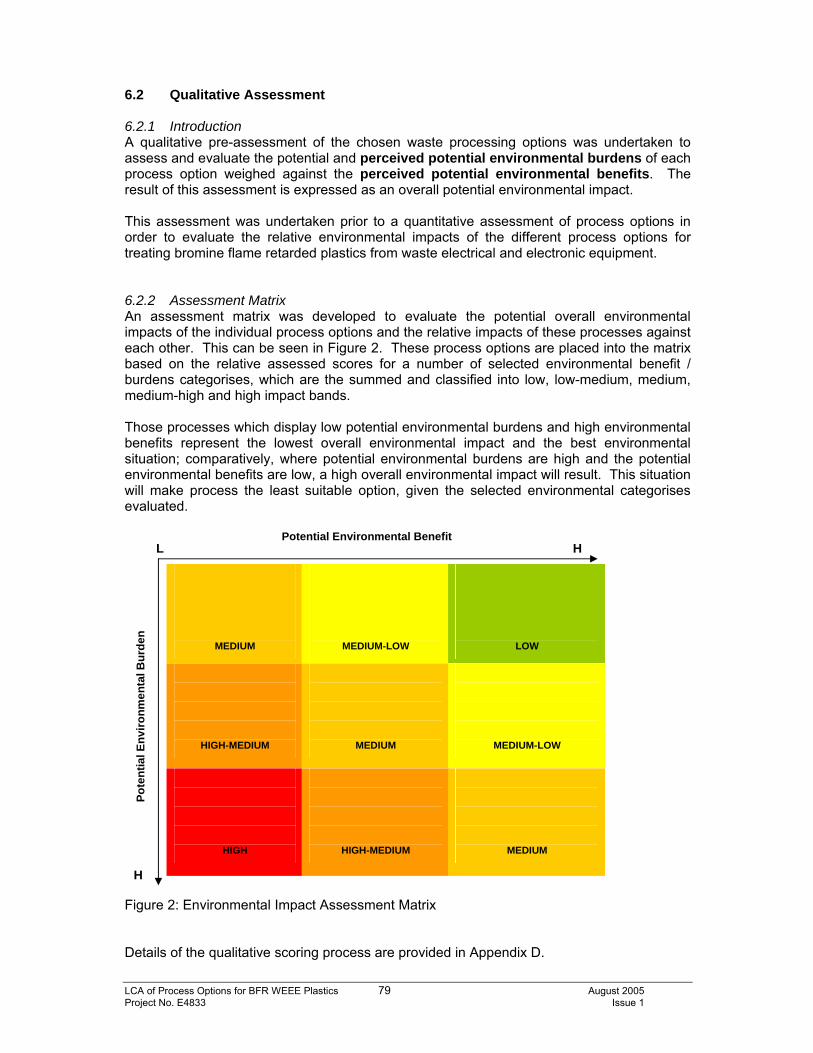
LCA of Process Options for BFR WEEE Plastics 79 August 2005 Project No. E4833 Issue 1
6.2 Qualitative Assessment 6.2.1 Introduction A qualitative pre-assessment of the chosen waste processing options was undertaken to assess and evaluate the potential and perceived potential environmental burdens of each process option weighed against the perceived potential environmental benefits. The result of this assessment is expressed as an overall potential environmental impact. This assessment was undertaken prior to a quantitative assessment of process options in order to evaluate the relative environmental impacts of the different process options for treating bromine flame retarded plastics from waste electrical and electronic equipment. 6.2.2 Assessment Matrix An assessment matrix was developed to evaluate the potential overall environmental impacts of the individual process options and the relative impacts of these processes against each other. This can be seen in Figure 2. These process options are placed into the matrix based on the relative assessed scores for a number of selected environmental benefit / burdens categorises, which are the summed and classified into low, low-medium, medium, medium-high and high impact bands. Those processes which display low potential environmental burdens and high environmental benefits represent the lowest overall environmental impact and the best environmental situation; comparatively, where potential environmental burdens are high and the potential environmental benefits are low, a high overall environmental impact will result. This situation will make process the least suitable option, given the selected environmental categorises evaluated.
Figure 2: Environmental Impact Assessment Matrix Details of the qualitative scoring process are provided in Appendix D.
MEDIUM
MEDIUM-LOW
LOW
HIGH-MEDIUM
MEDIUM
MEDIUM-LOW
HIGH
HIGH-MEDIUM
MEDIUM
Potential Environmental Benefit L H
H
Pote
ntia
l Env
ironm
enta
l Bur
den
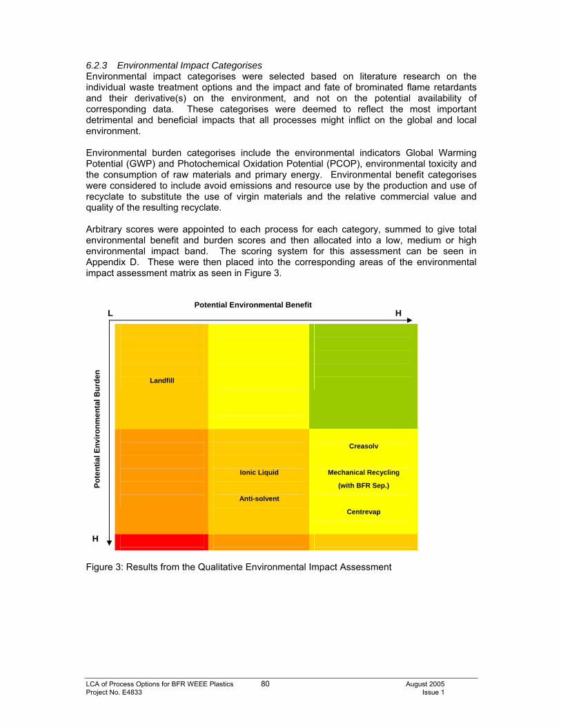
LCA of Process Options for BFR WEEE Plastics 80 August 2005 Project No. E4833 Issue 1
6.2.3 Environmental Impact Categorises Environmental impact categorises were selected based on literature research on the individual waste treatment options and the impact and fate of brominated flame retardants and their derivative(s) on the environment, and not on the potential availability of corresponding data. These categorises were deemed to reflect the most important detrimental and beneficial impacts that all processes might inflict on the global and local environment. Environmental burden categorises include the environmental indicators Global Warming Potential (GWP) and Photochemical Oxidation Potential (PCOP), environmental toxicity and the consumption of raw materials and primary energy. Environmental benefit categorises were considered to include avoid emissions and resource use by the production and use of recyclate to substitute the use of virgin materials and the relative commercial value and quality of the resulting recyclate. Arbitrary scores were appointed to each process for each category, summed to give total environmental benefit and burden scores and then allocated into a low, medium or high environmental impact band. The scoring system for this assessment can be seen in Appendix D. These were then placed into the corresponding areas of the environmental impact assessment matrix as seen in Figure 3.
Figure 3: Results from the Qualitative Environmental Impact Assessment
Landfill
Ionic Liquid
Anti-solvent
Creasolv
Mechanical Recycling
(with BFR Sep.)
Centrevap
Potential Environmental Benefit L H
H
Pote
ntia
l Env
ironm
enta
l Bur
den
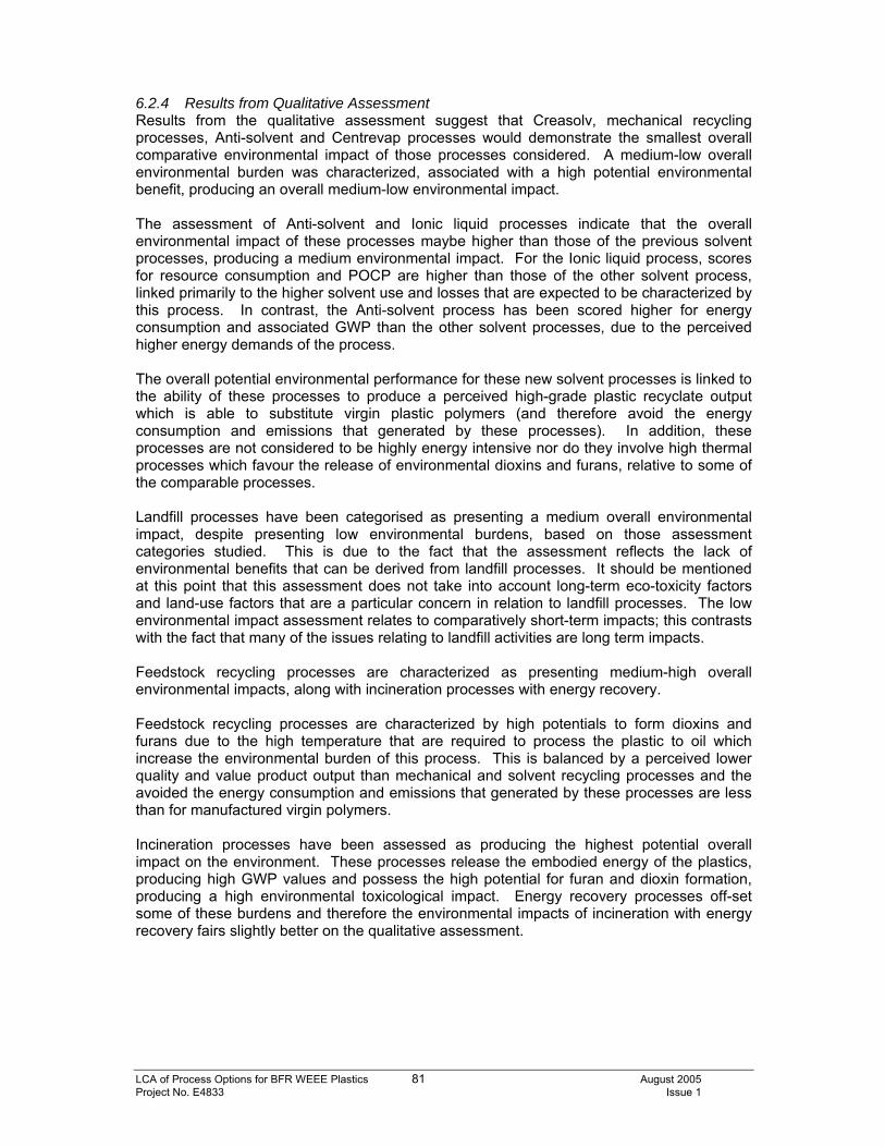
LCA of Process Options for BFR WEEE Plastics 81 August 2005 Project No. E4833 Issue 1
6.2.4 Results from Qualitative Assessment Results from the qualitative assessment suggest that Creasolv, mechanical recycling processes, Anti-solvent and Centrevap processes would demonstrate the smallest overall comparative environmental impact of those processes considered. A medium-low overall environmental burden was characterized, associated with a high potential environmental benefit, producing an overall medium-low environmental impact. The assessment of Anti-solvent and Ionic liquid processes indicate that the overall environmental impact of these processes maybe higher than those of the previous solvent processes, producing a medium environmental impact. For the Ionic liquid process, scores for resource consumption and POCP are higher than those of the other solvent process, linked primarily to the higher solvent use and losses that are expected to be characterized by this process. In contrast, the Anti-solvent process has been scored higher for energy consumption and associated GWP than the other solvent processes, due to the perceived higher energy demands of the process. The overall potential environmental performance for these new solvent processes is linked to the ability of these processes to produce a perceived high-grade plastic recyclate output which is able to substitute virgin plastic polymers (and therefore avoid the energy consumption and emissions that generated by these processes). In addition, these processes are not considered to be highly energy intensive nor do they involve high thermal processes which favour the release of environmental dioxins and furans, relative to some of the comparable processes. Landfill processes have been categorised as presenting a medium overall environmental impact, despite presenting low environmental burdens, based on those assessment categories studied. This is due to the fact that the assessment reflects the lack of environmental benefits that can be derived from landfill processes. It should be mentioned at this point that this assessment does not take into account long-term eco-toxicity factors and land-use factors that are a particular concern in relation to landfill processes. The low environmental impact assessment relates to comparatively short-term impacts; this contrasts with the fact that many of the issues relating to landfill activities are long term impacts. Feedstock recycling processes are characterized as presenting medium-high overall environmental impacts, along with incineration processes with energy recovery. Feedstock recycling processes are characterized by high potentials to form dioxins and furans due to the high temperature that are required to process the plastic to oil which increase the environmental burden of this process. This is balanced by a perceived lower quality and value product output than mechanical and solvent recycling processes and the avoided the energy consumption and emissions that generated by these processes are less than for manufactured virgin polymers. Incineration processes have been assessed as producing the highest potential overall impact on the environment. These processes release the embodied energy of the plastics, producing high GWP values and possess the high potential for furan and dioxin formation, producing a high environmental toxicological impact. Energy recovery processes off-set some of these burdens and therefore the environmental impacts of incineration with energy recovery fairs slightly better on the qualitative assessment.
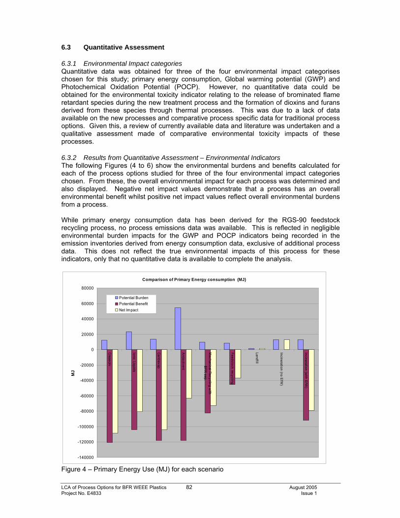
LCA of Process Options for BFR WEEE Plastics 82 August 2005 Project No. E4833 Issue 1
6.3 Quantitative Assessment 6.3.1 Environmental Impact categories Quantitative data was obtained for three of the four environmental impact categorises chosen for this study; primary energy consumption, Global warming potential (GWP) and Photochemical Oxidation Potential (POCP). However, no quantitative data could be obtained for the environmental toxicity indicator relating to the release of brominated flame retardant species during the new treatment process and the formation of dioxins and furans derived from these species through thermal processes. This was due to a lack of data available on the new processes and comparative process specific data for traditional process options. Given this, a review of currently available data and literature was undertaken and a qualitative assessment made of comparative environmental toxicity impacts of these processes. 6.3.2 Results from Quantitative Assessment – Environmental Indicators The following Figures (4 to 6) show the environmental burdens and benefits calculated for each of the process options studied for three of the four environmental impact categories chosen. From these, the overall environmental impact for each process was determined and also displayed. Negative net impact values demonstrate that a process has an overall environmental benefit whilst positive net impact values reflect overall environmental burdens from a process. While primary energy consumption data has been derived for the RGS-90 feedstock recycling process, no process emissions data was available. This is reflected in negligible environmental burden impacts for the GWP and POCP indicators being recorded in the emission inventories derived from energy consumption data, exclusive of additional process data. This does not reflect the true environmental impacts of this process for these indicators, only that no quantitative data is available to complete the analysis.
Comparison of Primary Energy consumption (MJ)
-140000
-120000
-100000
-80000
-60000
-40000
-20000
0
20000
40000
60000
80000C
reasolv
Ionic Liquids
Centrevap
Antisolvent
Mechanical R
ecycling with
BFR
sep.
Feedstock recycling
Landfill
Incineration (no EfW
)
Incineration (with E
fW)
MJ
Potential BurdenPotential BenefitNet Impact
Figure 4 – Primary Energy Use (MJ) for each scenario
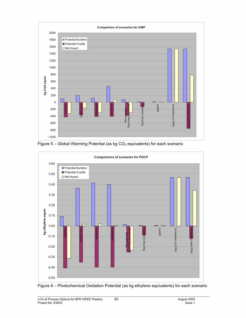
LCA of Process Options for BFR WEEE Plastics 83 August 2005 Project No. E4833 Issue 1
Comparison of scenarios for GWP
-1000
-800
-600
-400
-200
0
200
400
600
800
1000
1200
1400
1600
1800
2000
Creasolv
Ionic Liquids
Centrevap
Antisolvent
Mechanical R
ecyclingw
ith BFR
sep.
Feedstock recycling
Landfill
Incineration (no EfW
)
Incineration (with E
fW)
kg C
O2
equi
v.Potential BurdensPotential CreditsNet Impact
Figure 5 – Global Warming Potential (as kg CO2 equivalents) for each scenario
Comparisons of scenarios for POCP
-0.50
-0.40
-0.30
-0.20
-0.10
0.00
0.10
0.20
0.30
0.40
0.50
0.60
Creasolv
Ionic Liquids
Centrevap
Antisolvent
Mechanical R
ecyclingw
ith BFR
sep.
Feedstock recycling
Landfill
Incineration (no EfW
)
Incineration (with E
fW)
kg e
thyl
ene
equi
v.
Potential BurdensPotential CreditsNet Impact
Figure 6 – Photochemical Oxidation Potential (as kg ethylene equivalents) for each scenario
LCA of Process Options for BFR WEEE Plastics 84 August 2005 Project No. E4833 Issue 1
6.3.3 Environmental Toxicology – Qualitative Assessment Landfill Processes Brominated flame retardants associated with plastic materials are likely to show little short-term volatisation from the plastic and leaching into the ground once landfilled. This is particularly relevant for reactive brominated flame retardants which are chemically bonded into the polymer matrix, rather than being added to the polymer prior to, during or following polymerisation. In the long term however, as the plastic starts to break down, which may take hundreds of years, the potential does exist for flame retardants to be released into the environment. The potential for the formation of dibenzo-p-dioxins and furans from brominated flame retardants is associated with thermal processes, which do not typically exist at landfill sites. Therefore, the potential for these species to be formed is low. The exception to this is during landfill fires, which are generally accidental uncontrolled occurrences. Where landfill fires do occur, the potential for brominated dioxins and furans to be generated does exist, although the temperatures generated during such fires and the residence times of these compounds is likely to be longer than those used in experimental laboratory conditions, making predictions on the amounts of dioxins and furans that can be generated very difficult. Mechanical Recycling Processes A number of studies, including works undertaken by Riess et al. (1998), Meyer (1993), GfA (1999) and Hamm et al. (2001) suggest that dibenzo-p-dioxins and furans are not formed during normal extrusion and injection moulding processes. While the studies undertaken by Reiss et al (1998) and Meyer (1993) found that the levels of dioxins and furans in these recycled products exceeded the levels imposed by the German Dioxin Ordinance, the levels did not increase as a result of the recycling process. This is supported by work undertaken by GfA (1999) on Deca-BDE in HIPS plastics which related levels of dioxins and furans within the processed plastics to trace quantities found in the polymer prior to recycling. The potential for dioxin / furan formation is associated with those processing stages which involve elevated temperatures, and for mechanical recycling processes, this is most applicable to the extrusion and moulding processes. These studies suggest that the dioxin / furan content of the recycled product is not influenced by the recycling processes itself, but by the dioxin / furan content of the input material; as such recycling of BFR plastics may only be feasible if mixed with other non-BFR plastics. However, dependant on material input and the use of suitable recycling conditions, the emissions of dioxins and furans and their concentrations in the recyclate can meet stringent levels imposed by the German Dioxin Ordinance. It is less clear as to whether recycling processes result in a reduction of the higher brominated congeners to the lower brominated congeners which show greater environmental toxicity; work by Riess et al (1998) suggests that changes in the distribution of these congeners does occur during recycling processes, while works by GfA in 1999 using deca-BDE however found that there was no formation of the lower brominated diphenyl ethers. The potential for higher brominated congeners to reduce to the lower brominated congeners is dependant on the polymer and flame retardant composition of the recycled plastic material; this differs between studies or is not characterised making comparisons or analyses difficult. However, the plastic material considered for mechanical recycling within this study has undergone some polymer sorting to remove those stryenic polymers with which a high proportion of BFR species are associated and as such, the potential for the release of BFR species from mechanical recycling processes would be expected to be low and the resulting material of a quality to meet the minimum levels imposed by the German Dioxin Ordinance.
LCA of Process Options for BFR WEEE Plastics 85 August 2005 Project No. E4833 Issue 1
New Solvent-based Process Options Brominated dibenzo-p-dioxins and furans may be present in small quantities as contaminants within brominated flame retardant species. The presence of these species following disposal and recycling activities does not therefore automatically ensure that they have been formed as a direct result of the process. However, no emissions analysis was conducted regarding dioxin and furan species formation or the release of BFR compounds, and, as novel processes, no comparable data is available from previous publicly available works from which an analysis can be made. Therefore, the potential for these processes to release BFR during the treatment process or the potential for the formation of dioxins and furans is unknown at present. The formation of dioxins is greatest at temperatures approaching 250°C - 300°C, whilst the maximum temperature expected to be achieved during these solvent processes is 60°C. As such, it might be expected that the potential for dioxin and furan formation is lower than thermal processes such as feedstock recycling or incineration. However, the extrusion phase of these processes involves temperatures that are elevated above those expected during the extraction processes themselves, suggesting that the potential for new dioxin / furan formation exists at this stage. It is unclear at present the potential of these processes to generate dioxins and furans during full-scale operations, particularly during plastic extrusion stages or how these processes compare to mechanical recycling in terms of dioxin and furan formation. However, it maybe expected that the potential for these compounds to be formed is lower than that of either incineration or feedstock recycling processes due to the lower temperatures generated and the lower-oxygen environments utilised by these processes. There is also concern about the potential for dioxin / furans to build-up in the solvent recovery system of these processes, although this remains to be assessed (Axion, 2005). This concern should be investigated and addressed prior to commencement of full scale trials. In contrast, the depolymerisation of the plastic during these processes may release reactive BFR species that are typically locked into the polymer structure of some BFR plastics and not available for release during traditional mechanical recycling processes. The release of BFR compounds may therefore be greater than mechanical recycling processes, particularly where the BFR waste is emptied into waste containers for disposal. Therefore, while not quantifiable at present it is possible to qualify them in relation to other processes considered in this study. While it might be expected that the emissions of these species exceeds those of mechanical recycling and landfill processes, it may also be expected that these emissions fall below those expected in thermal processes such as feedstock recycling and incineration. While not a focus of the environmental toxicological assessment, the use of solvents in these processes may introduce additional environmental impact issues associated with their use and disposal, particularly as the waste generated through these processes are hazardous wastes. RGS-90 Feedstock Recycling Process The RGS-90 feedstock recycling process is designed to process PVC plastic waste through a hydrolysis process to produce oil, salt and minerals, for which end markets exist for all produced materials.
LCA of Process Options for BFR WEEE Plastics 86 August 2005 Project No. E4833 Issue 1
A review of the this process in the final report on; ‘PVC Recovery Options Concept for Environmental and economic System Analysis’ by PE Europe GmbH details that the formation of dioxins and furans is expected. This is a result of the process technology itself rather than the input material into the process. While the release of these compounds into the environment can be controlled through the use of primary and secondary scrubber systems and catalytic reactors, the potential for these compounds to be formed does exist, particularly downstream of the post combustion zone during the cool down phase in the boiler, through the so-called De-Novo-Synthesis process; this is optimal at temperature of 250°C – 300°C. While is unclear what process changes would be required for this system to operate using brominated flame retardant plastic waste, the potential for dioxin and furan does exist, at levels approaching those expected through incineration processes and as such a similar environmental toxicological score would be expected. Specific emissions monitoring would be required to evaluate the true level of dioxin and furan formation from this process and those abatement measures that would be required in order for emission standards to be achieved. Incineration Processes Halogenated dibenzo-p-dioxins and furans are formed during thermal processes involving halogenated compounds. Optimal dioxin and furan formation is achieved at temperatures of 250°C – 300°C and at temperatures over 800°C the complete destruction of these species appears to occur. While proper incineration design can reduce the potential release to the environment, these species are formed during such processes. Several factors influence the formation of these furans including, temperature, residence time at that temperature, the presence of oxygen, the type of polymer matrix and the presence of other additives, particularly antimony trioxide. While it is clear from a number of studies that polybrominated dioxins and furans are formed when heated, either alone or in mixed polymer matrices, quantification is difficult due the lack of analytical standards and experimental conditions. In a recent study by Söderström and Markland (2001), the ability of bromine and chlorine to form halogenated dibenzo-p-dioxins and furans during the co-combustion of Deca BDE or HBCD or TBBPA with municipal solid waste (MSW) was investigated. Results showed that under normal conditions, the flame retardants are completely destroyed and that there are no differences in the formation of dibenzo-p-dioxins or furans between the different flame retardants. However, co-combustion of BFR compounds with MSW is required in order to reduce the emissions of dibenzo-p-dioxins and furans to comply with current emissions standards. In additional studies, no relationship between dioxin emissions from incinerators and the bromine level of the waste was found (Ten Berg, 1995), while Tange et al (2001) concluded that the formation of halogenated DBD and DBF was dependant on the products of incomplete combustion. Levels of halogenated dibenzo-p-dioxins and furans levels appeared to reach a constant level at bromine loads of 500 – 1,000mg/kg. While proper incinerator design can reduce the release of dibenzo-p-dioxins and furans into the environment, incineration processes have the highest potential for the formation of dibenzo-p-dioxins and furans. It maybe expected that complex scrubber systems are required if BFR plastics are incinerated and studies suggest that high volumes of MSW are also required in order to dilute the concentrations of dibenzo-p-dioxins and furans emissions generated by BFR combustion to levels which will fall within current standards. In addition, while many incineration trials have been conducted using mixed WEEE plastic waste, the concentrates of BFR within these materials is not believed to be as great as those resulting from plastic pre-sorting stages of this study and the focus of our comparative processes.
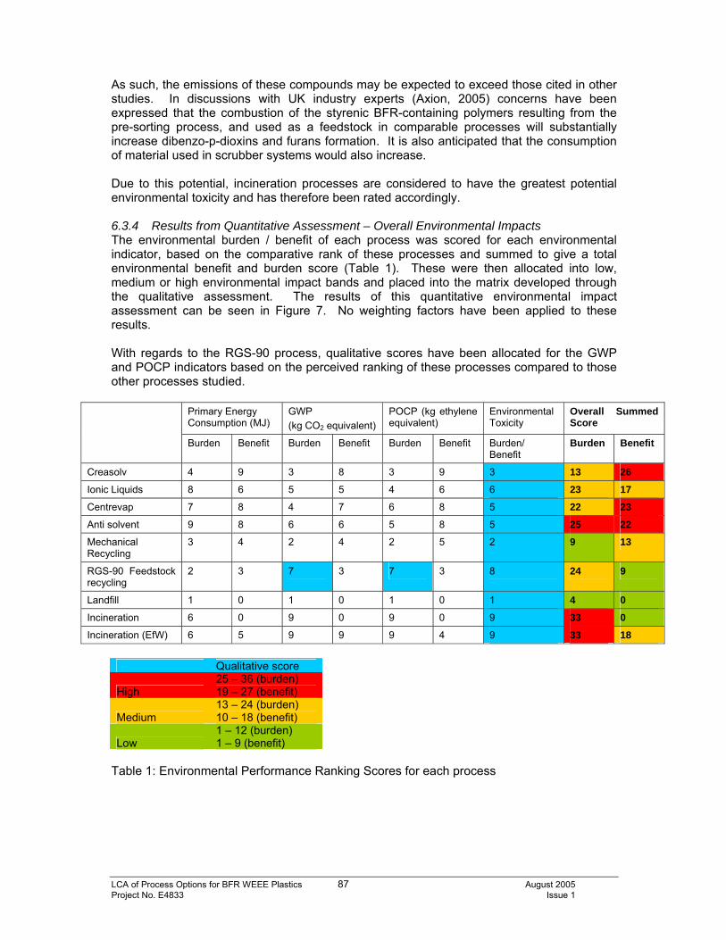
LCA of Process Options for BFR WEEE Plastics 87 August 2005 Project No. E4833 Issue 1
As such, the emissions of these compounds may be expected to exceed those cited in other studies. In discussions with UK industry experts (Axion, 2005) concerns have been expressed that the combustion of the styrenic BFR-containing polymers resulting from the pre-sorting process, and used as a feedstock in comparable processes will substantially increase dibenzo-p-dioxins and furans formation. It is also anticipated that the consumption of material used in scrubber systems would also increase. Due to this potential, incineration processes are considered to have the greatest potential environmental toxicity and has therefore been rated accordingly. 6.3.4 Results from Quantitative Assessment – Overall Environmental Impacts The environmental burden / benefit of each process was scored for each environmental indicator, based on the comparative rank of these processes and summed to give a total environmental benefit and burden score (Table 1). These were then allocated into low, medium or high environmental impact bands and placed into the matrix developed through the qualitative assessment. The results of this quantitative environmental impact assessment can be seen in Figure 7. No weighting factors have been applied to these results. With regards to the RGS-90 process, qualitative scores have been allocated for the GWP and POCP indicators based on the perceived ranking of these processes compared to those other processes studied.
Primary Energy Consumption (MJ)
GWP (kg CO2 equivalent)
POCP (kg ethylene equivalent)
Environmental Toxicity
Overall Summed Score
Burden Benefit Burden Benefit Burden Benefit Burden/ Benefit
Burden Benefit
Creasolv 4 9 3 8 3 9 3 13 26
Ionic Liquids 8 6 5 5 4 6 6 23 17
Centrevap 7 8 4 7 6 8 5 22 23
Anti solvent 9 8 6 6 5 8 5 25 22 Mechanical Recycling
3 4 2 4 2 5 2 9 13
RGS-90 Feedstock recycling
2 3 7 3 7 3 8 24 9
Landfill 1 0 1 0 1 0 1 4 0
Incineration 6 0 9 0 9 0 9 33 0
Incineration (EfW) 6 5 9 9 9 4 9 33 18 Qualitative score
High 25 – 36 (burden) 19 – 27 (benefit)
Medium 13 – 24 (burden) 10 – 18 (benefit)
Low 1 – 12 (burden) 1 – 9 (benefit)
Table 1: Environmental Performance Ranking Scores for each process
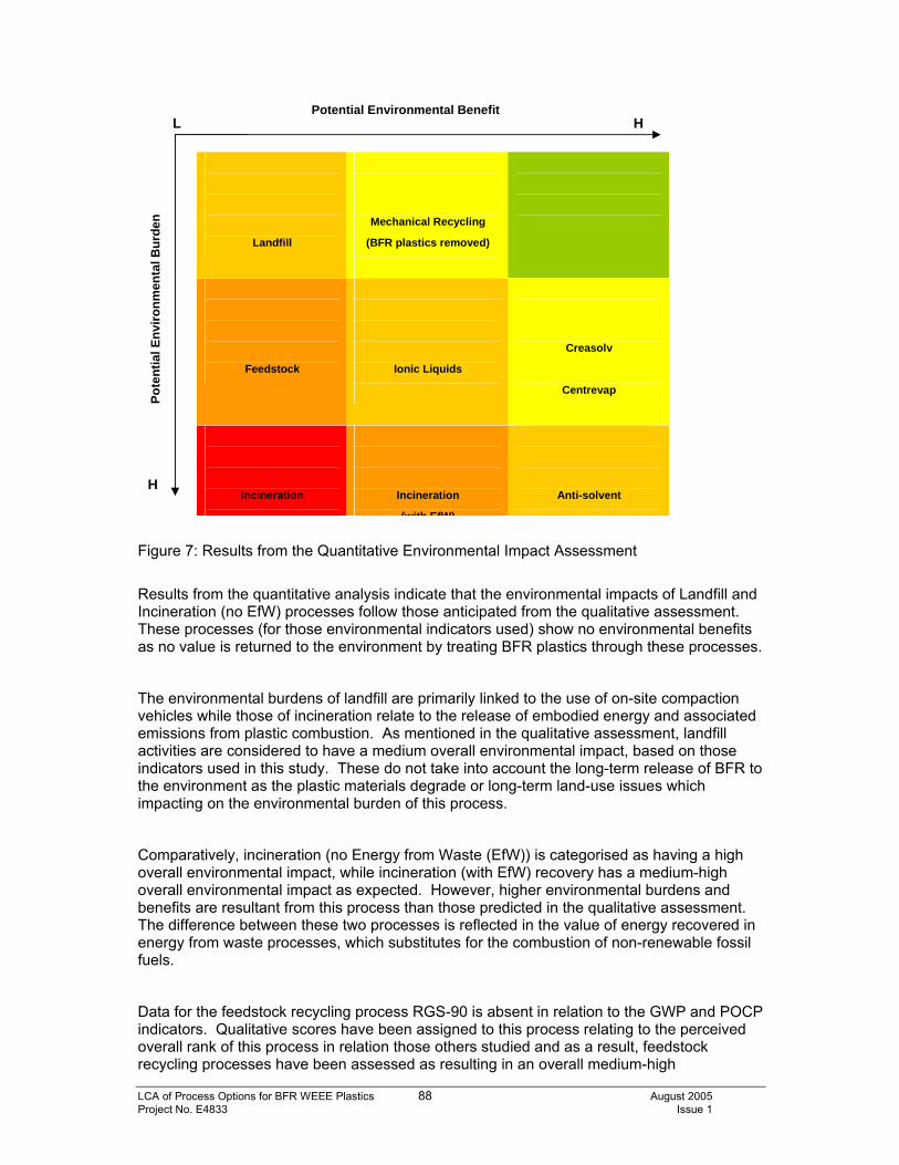
LCA of Process Options for BFR WEEE Plastics 88 August 2005 Project No. E4833 Issue 1
Figure 7: Results from the Quantitative Environmental Impact Assessment
Results from the quantitative analysis indicate that the environmental impacts of Landfill and Incineration (no EfW) processes follow those anticipated from the qualitative assessment. These processes (for those environmental indicators used) show no environmental benefits as no value is returned to the environment by treating BFR plastics through these processes.
The environmental burdens of landfill are primarily linked to the use of on-site compaction vehicles while those of incineration relate to the release of embodied energy and associated emissions from plastic combustion. As mentioned in the qualitative assessment, landfill activities are considered to have a medium overall environmental impact, based on those indicators used in this study. These do not take into account the long-term release of BFR to the environment as the plastic materials degrade or long-term land-use issues which impacting on the environmental burden of this process.
Comparatively, incineration (no Energy from Waste (EfW)) is categorised as having a high overall environmental impact, while incineration (with EfW) recovery has a medium-high overall environmental impact as expected. However, higher environmental burdens and benefits are resultant from this process than those predicted in the qualitative assessment. The difference between these two processes is reflected in the value of energy recovered in energy from waste processes, which substitutes for the combustion of non-renewable fossil fuels.
Data for the feedstock recycling process RGS-90 is absent in relation to the GWP and POCP indicators. Qualitative scores have been assigned to this process relating to the perceived overall rank of this process in relation those others studied and as a result, feedstock recycling processes have been assessed as resulting in an overall medium-high
Potential Environmental Benefit L H
H
Pote
ntia
l Env
ironm
enta
l Bur
den
Landfill
Mechanical Recycling
(BFR plastics removed)
Feedstock
Ionic Liquids
Creasolv
Centrevap
Incineration
Incineration
(with EfW)
Anti-solvent
LCA of Process Options for BFR WEEE Plastics 89 August 2005 Project No. E4833 Issue 1
environmental impact. Environmental toxicity has been scored as being high for this process, with process temperature generated being those approaching optimal for dioxin and furan formation.
The process also utilises a portion of the plastic material input as fuel to drive the process; the corresponding emissions have been allocated as falling between those of incineration processes and that of the Anti solvent process.
The results of the quantitative analysis indicates that the best environmentally performing processes involving the treatment of BFR plastics are the Creasolv and the Centrevap processes which demonstrate a low-medium overall environmental impact. Comparatively, the mechanical recycling of those plastics from which the styrenic BFR-containing polymers have been removed also produces a corresponding low-medium overall environmental impact, although the perceived environmental burdens of this process are lower than those of the best performing new solvent processes. This is primarily associated with the use of solvents in the new solvent processes.
Analysis of the comparative performance of the new processes, considering the four environmental indicators selected, are similar for all four of these processes. Primary energy consumption is seen to be greatest for the Anti-solvent and Ionic Liquid processes and this is reflected in the results for GWP, which are linked primarily to energy consumption for these processes. Comparative environmental benefits (through avoided virgin polymer production) for these and the Creasolv process are also similar.
However, the greatest variation between these processes is reflected in the results for the POCP. This is a direct result of the differences in the type of solvent used and the perceived solvent losses from these processes.
Mass balance data suggests that lowest solvent loss occurs from the Creasolv process; this is reflected in the overall potential environmental impact of this process for the POCP indicator and is the only solvent process for which an overall negative environmental impact was achieved. Comparative data for the Ionic Liquid process suggests that the greatest solvent losses occurs from this process, while the Anti-solvent process displays the greatest overall environmental impact in relation to this indicator. As a result, both these processes indicate an overall medium environmental impact, with the Anti-solvent process displaying high environment burdens and benefits compared to the medium environmental burdens and benefits of the Ionic Liquid process.
Creasolv and Centrevap process appear to offer the lowest environmental impacts of the new solvent processes investigated, for those environmental impact categories selected. These appear to compare favourably with those mechanical recycling processes from which the styrenic BFR containing plastic polymers have separated. It should be high-lighted that the performance of all these solvent processes is dependant on the efficiencies of the solvent recovery systems in place. The Creasolv process in particular is distinguished as presenting low solvent losses and high solvent recovery efficiencies, however, if this efficiency is reduced, the environmental burden of the process will increase, along with results for the POCP environmental indicator. This would increase the overall environmental burden of the process.
LCA of Process Options for BFR WEEE Plastics 90 August 2005 Project No. E4833 Issue 1
Similar effects are expected for the other solvent processes, if the efficiencies of the solvent recovery systems are reduced.
LCA of Process Options for BFR WEEE Plastics 91 August 2005 Project No. E4833 Issue 1
7.0 Summary and Conclusions Qualitative and a quantitative environmental impact assessment of the process options investigated in this study appear to show that Creasolv and Centrevap have the lowest potential environmental impacts, alongside mechanical recycling, for those environmental indicators used. These new solvent processes appear more favourable than the Ionic liquids and Anti-solvent processes, which have higher comparable solvent consumptions and/or energy demands per unit input/output of plastic material. However, it should be high-lighted that the performance of all these solvent processes is particularly dependant on the efficiencies of the solvent recovery systems in place. If these efficiencies are reduced, the environmental burdens of these processes would be expected to increase resulting from higher POCP impacts and thereby increasing the overall environmental impact of the process. No emissions or analysis data was available on the potential of these processes to form dibenzo-p-dioxins and furans during extrusion and concerns have been expressed that these compounds may have the potential to build up in the solvent recovery system. These should be assessed and quantified prior to commencement of any full scale trial. However, it may expected that the potential release of dibenzo-p-dioxin and furans by these processes is lower than those of feedstock recycling or incineration due to the significantly lower operating temperatures and low-oxygen environments used by these processes. In contrast, both the qualitative and quantitative assessments show the greatest potential environmental impacts for the incineration processes. These have been assessed as producing high and medium-high potential environmental impacts based on the considerably higher GWP values to other treatment processes, and the perceived greater potential for dibenzo-p-dioxin and furan formation. In particular, industry experts have expressed concerns that the combustion of the styrenic BFR-containing polymers resulting from the pre-sorting process, and used as a feedstock in comparable processes will substantially increase dibenzo-p-dioxins and furans formation. It is also anticipated that the consumption of materials used in scrubber systems would also increase and that power generation efficiency would be compromised by the build-up of bromine and metal salts in the furnace super-heater. While practical studies have been conducted that indicate that the formation of these compounds is not dependant on the bromine input into the process, but more on the process technology and that the release of these compounds into the environmental can be controlled by the installation of complex catalysts and scrubber systems, the environmental assessment has been conducted with a view to the potential of the waste processes to form these compounds. Feedstock processes have been considered as providing similar potential to form these compounds. While a lack of quantitative data hinders the comparability of this process with those others studied, it is considered that this process may offer a medium environmental impact based on comparatively lower GWP and energy consumption values than incineration processes. Landfill activities are considered to have a medium environmental impact, primarily based on low energy demands, however there are also low environmental benefits from the process. This is not necessarily a true reflection of the environmental impact of this process, as this waste ‘treatment’ option operates over a longer time scale than other processes considered, for example the potential release of BFR into the environment will operate over a period of hundreds of years as the plastic materials start to break down. In addition, land use indicators, which would be of particular importance to landfill sites, were not considered in this study.
LCA of Process Options for BFR WEEE Plastics 92 August 2005 Project No. E4833 Issue 1
8.0 Limitations of the Study The quality of the analysis of the environmental impacts of waste treatment options for BFR plastic waste has been restricted by a lack of process specific emissions data, including dioxin, furan and BFR emissions for the new solvent processes and the feedstock recycling process RGS-90. Publicly available generic data has been utilised to fill in the data gaps, where possible, however, quantitative data gaps still exist with regards to BFR, dioxin and furan emissions. In addition, concerns were also raised about the potential for dibenzo-p-dioxin and furans to build up in the solvent recovery systems of the new solvent processes. Quantitative emissions data should be gathered to fill-in the data gaps in these processes and address those concerns raised about potential dibenzo-p-dioxin and furan build-up in solvent recovery systems which will affect the operating efficiency of large scale processes. The study also did not consider the environmental impacts of the generation of hazardous waste as a consequence of the treatment process, the environmental impacts of solvent use nor did it consider emissions to water, on which some of the solvent process may have significant impact. To complete a holistic assessment of the environmental impact for these processes, these environmental impacts should be investigated. It is also recommended that this study should be supported by process-specific emissions monitoring for the new solvent processes in order to validate the results of this investigation.
LCA of Process Options for BFR WEEE Plastics 93 August 2005 Project No. E4833 Issue 1
9.0 References 1. Action Energy Website: www.actionenergy.org.uk 2. APME (1997a) – Eco-profiles of the European Plastics Industry Report 4: High
Impact Polystyrene (HIPS) 3. APME (1997b) - Ecoprofiles of the European plastics Industry, report 13 , Co-
polymers of Acrylonitrile-Butadiene- Styrene (ABS) and Styrene-Acrylonitrile (SAN), 4. APME (1997b) – Feedstock Recycling of Electrical and Electronic Plastics Waste 5. APME (1997c) - Eco-profiles of the European Plastics Industry Report 13:
Polycarbonate 6. Axion Recycling Ltd. (2005) – Personal Communication. 7. Boustead, I. (2003) – Eco-profiles of the European Plastics Industry: Methodology. A
Report for APME. 8. BSI EN ISO 14042 (2000) – Environmental Management – Life Cycle Assessment –
Life Cycle Impact Assessment 9. BSI EN ISO 14041 (1998) – Environmental Management – Life Cycle Assessment –
Goal and scope Definition and Inventory Analysis 10. BSI EN ISO 14040 (1997) – Environmental Management – Life Cycle Assessment –
Principles and Framework. 11. Eulálio, C., Capiati, N. J. and S. E. Barbosa – Municipal Plastic Waste – Alternatives
for Recycling with Profit. Taken from the website: www.sperecycling.org 12. European Environment Agency (1997 – Life Cycle Assessment: A guide to
approaches, experiences and information sources. Environmental Issue Series No. 6 13. European Union Risk Assessment Report (2003) – diphenyl ether – octabromo
derivative. CAS No:32536-52-0. EINECS No. 251-087-9. 14. European Union Risk Assessment Report (Draft)(2002) - Bis(pentabromophenyl)
ether CAS No: 1163-19-5.EINECS No: 214-604-9. 15. European Union Risk Assessment Report (2001) – diphenyl ether – pentabromo
derivative. CAS No: 32534-81-9. EINECS No. 251-084-2 16. GfA (1999). Analysis of a decabromodiphenyl oxide blend, a HIPS plastic, the HIPS
plastic containing the DecaBDPO and Sb2O3 and the repeated recycled HIPS/Sb2O3/DecaBDPO plastic for partially brominated diphenyl ethers and 8 polybrominated dibenzo(p)dioxin and dibenzofuran congeners. Report 60425-001 B01, Gesellschaft für Arbeitsplatz- und Umwelanalytik mbH, August 26, 1999.
17. Hamm S., Strikkeling M., Ranken P. and Rothenbacher K.P. (2001): Determination of Polybrominated Diphenyl Ethers and PBDD/Fs during the Recycling of High Impact Polystyrene Containing Decabromodiphenylether and Antimony Oxide. Chemosphere, 44/6 (2001) 1353-1360.
18. Kieper H. (2000): Workplace measurements for PBDF/Ds during recycling of HIPS/Sb2O3/ DecaBDPO plastic at an extruder at the Technical University of Erlangen-Nürnberg; Workplace assessment, GfA-Gesellschaft für Arbeitsplatz- und Umweltanalytik mbH Report No. 60425-002 B01.
19. Kreißig, J. et al (2003) – Final Report: PVC Recovery Options Concepts for Environmental and Economic System Analysis. Produced by PE Europe GmbH.
20. Institute of Chemical Engineers Website: www.icheme.org/sustainability/metrics.pdf 21. Meyer H, Neupert M, Plump W, and Willenberg B (1993). Flame retardants ABS/PC
blends in office machines as examples. Kunststoffe 83, 253-257. 22. McDougall, F.R, White, P.R, Franke, M. and Hindle, (2001) - ‘Integrated Solid Waste
Management: A life-cycle Inventory’. Published by Blackwell Science, Oxford, UK. 23. National Air Emissions Inventory Website: www.aeat.co.uk/netcen/airqual/naei 24. OECD (2004) Brominated Flame Retardants (BFRs): Hazard/Risk Information
Sheets.
LCA of Process Options for BFR WEEE Plastics 94 August 2005 Project No. E4833 Issue 1
25. Riess M, Ernst T, Popp R, Schubert T, Thoma H, Vierle O, Ehrenstein GW and van
Eldik R (1998). Analysis of flame retarded polymers and recycling materials. Organohalogen Compounds, 35, 443-446.
26. Söderström G and Marklund S (2001). Combustion of brominated flame retardants. Second International Workshop on Brominated Flame Retardants, May 14-16, Stockholm University, Sweden, pp65-70.
27. Tange L, Vehlow J and Drohmann D (2001). Bromine recovery in incinerators and alternative processes from plastics of E&E equipment containing brominated flame retardants as a sustainable solution. Second International Workshop on Brominated Flame Retardants, May 14-16, Stockholm University, Sweden, pp125-129.
28. Ten Berge W (1995). Risk assessment in relation to European Regulatory Requirements. Conference Proceedings “Legislation and Environment Conference”, European Brominated Flame Retardant Industry Panel, 18 September 1995.
29. Tohka, A. and R. Zevenhoven (2002) – Processing Wastes and Waste-derived fuels Containing Brominated Flame Retardants.
30. van Schijndel. P, van Kasteren, J. TU Eindhoven (2004) - Recycling of WEEE plastic waste at PHB’. A Study for European Brominated Flame Retardant Industry Panel
31. WRAP (2004) – Materials and Products from UK-sources PVC-rich waste. Project no. PLA7-013
32. WRAP (2005) – Develop a Process to Separate Brominated Flame Retardants from WEEE Polymers (Interim Report). Project no. PLA-037.
LCA of Process Options for BFR WEEE Plastics 95 August 2005 Project No. E4833 Issue 1
10.0 Glossary ABS Acrylonitrile Butadiene Styrene AP Acidification Potential APME Association of Plastic Manufacturers in Europe BFR Brominated Flame Retardants BDE Diphenyl ethers CFC Chlorofluorocarbons COD Chemical Oxygen Demand DBD Dibenzo-dioxins DBF Dibenzo-furans E & E Electrical and Electronic EfW Energy from Waste EP Eutrophication Potential GWP Global Warming Potential HBCD Hexabromocyclododecane HIP High Impact Polystyrene LCA Life Cycle Assessment MSW Municipal Solid Waste NETCEN National Environment Technology Centre NMVOC Non-methane Volatile Organic Compounds NOx Nitrogen oxides ODP Ozone Depletion Potential PBB Polybrominated biphenyls PBDE Polybrominated Diphenyl ethers PC Polycarbonate POCP Photochemical Oxidation Potential PVC Polyvinyl Chloride TBBPA Tetrabromobisphenol-A TBPE 1,2- (tribromophenoxy) ethane VOC Volatile Organic Compounds WEEE Waste Electrical and Electronic Equipment WRAP Waste and Resources Action Programme

LCA of Process Options for BFR WEEE Plastics 96 August 2005 Project No. E4833 Issue 1
APPENDIX A
REPORT CONDITIONS

LCA of Process Options for BFR WEEE Plastics 97 August 2005 Project No. E4833 Issue 1
WHITE YOUNG GREEN ENVIRONMENTAL
REPORT CONDITIONS
LIFE CYCLE ASSESSMENT: SUMMARY REPORT OF
SELECTED TREATMENT PROCESSES FOR WEEE PLASTICS CONTAINING BROMINATED FLAME RETARDANTS
This Life Cycle Assessment summary report is produced solely for the benefit of Axion Recycling and no liability is accepted for any reliance placed on it by any other party unless specifically agreed in writing otherwise. This report refers, within the limitations stated, to the operational processes as per the information supplied to WYGE. No warranty is given as to the possibility of future changes in the design of these processes. This report is based on reference data provided by Axion Recycling, accessible referenced records and information supplied by those parties referenced in the text. Some of the opinions are based on unconfirmed data and information and are presented as the best that can be obtained without further extensive research. Whilst confident in the findings detailed within this report because there are no exact UK definitions of these matters, being subject to risk analysis, we are unable to give categorical assurances that they will be accepted by authorities or funds etc. without question as such bodies often have unpublished, more stringent objectives. This report is prepared for the proposed uses stated in the report and should not be used in a different context without reference to WYGE. In time improved practices, data quality or amended legislation may necessitate a re-assessment.
LCA of Process Options for BFR WEEE Plastics 98 August 2005 Project No. E4833 Issue 1
APPENDIX B
ENERGY CONVERSION FACTORS
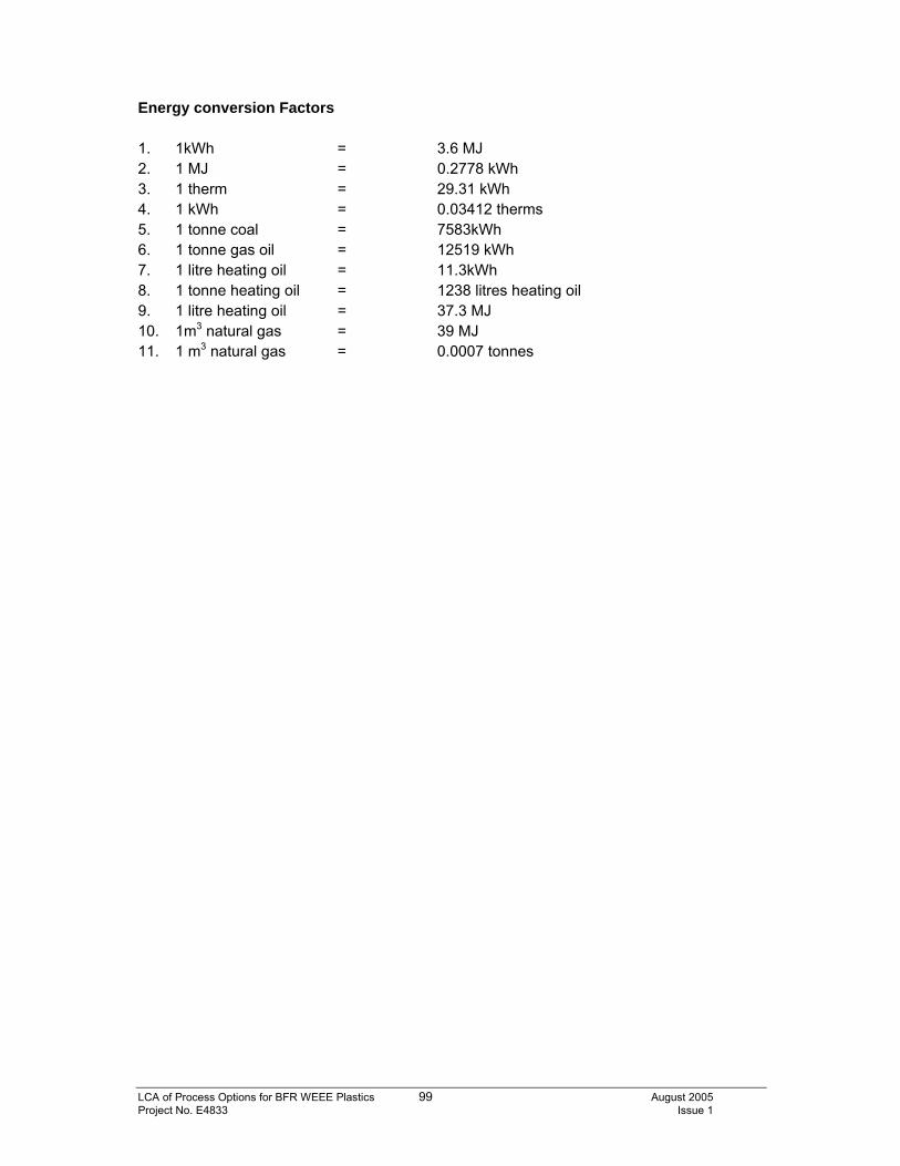
LCA of Process Options for BFR WEEE Plastics 99 August 2005 Project No. E4833 Issue 1
Energy conversion Factors 1. 1kWh = 3.6 MJ 2. 1 MJ = 0.2778 kWh 3. 1 therm = 29.31 kWh 4. 1 kWh = 0.03412 therms 5. 1 tonne coal = 7583kWh 6. 1 tonne gas oil = 12519 kWh 7. 1 litre heating oil = 11.3kWh 8. 1 tonne heating oil = 1238 litres heating oil 9. 1 litre heating oil = 37.3 MJ 10. 1m3 natural gas = 39 MJ 11. 1 m3 natural gas = 0.0007 tonnes
LCA of Process Options for BFR WEEE Plastics 100 August 2005 Project No. E4833 Issue 1
APPENDIX C
ASSUMPTIONS
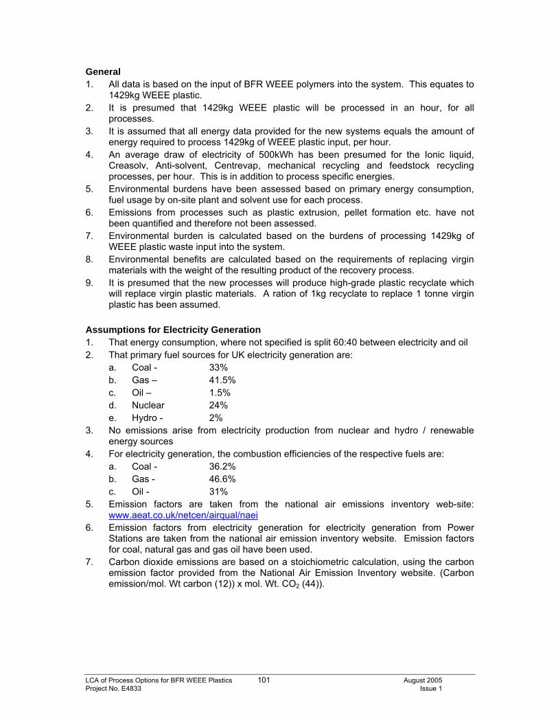
LCA of Process Options for BFR WEEE Plastics 101 August 2005 Project No. E4833 Issue 1
General 1. All data is based on the input of BFR WEEE polymers into the system. This equates to
1429kg WEEE plastic. 2. It is presumed that 1429kg WEEE plastic will be processed in an hour, for all
processes. 3. It is assumed that all energy data provided for the new systems equals the amount of
energy required to process 1429kg of WEEE plastic input, per hour. 4. An average draw of electricity of 500kWh has been presumed for the Ionic liquid,
Creasolv, Anti-solvent, Centrevap, mechanical recycling and feedstock recycling processes, per hour. This is in addition to process specific energies.
5. Environmental burdens have been assessed based on primary energy consumption, fuel usage by on-site plant and solvent use for each process.
6. Emissions from processes such as plastic extrusion, pellet formation etc. have not been quantified and therefore not been assessed.
7. Environmental burden is calculated based on the burdens of processing 1429kg of WEEE plastic waste input into the system.
8. Environmental benefits are calculated based on the requirements of replacing virgin materials with the weight of the resulting product of the recovery process.
9. It is presumed that the new processes will produce high-grade plastic recyclate which will replace virgin plastic materials. A ration of 1kg recyclate to replace 1 tonne virgin plastic has been assumed.
Assumptions for Electricity Generation 1. That energy consumption, where not specified is split 60:40 between electricity and oil 2. That primary fuel sources for UK electricity generation are:
a. Coal - 33% b. Gas – 41.5% c. Oil – 1.5% d. Nuclear 24% e. Hydro - 2%
3. No emissions arise from electricity production from nuclear and hydro / renewable energy sources
4. For electricity generation, the combustion efficiencies of the respective fuels are: a. Coal - 36.2% b. Gas - 46.6% c. Oil - 31%
5. Emission factors are taken from the national air emissions inventory web-site: www.aeat.co.uk/netcen/airqual/naei
6. Emission factors from electricity generation for electricity generation from Power Stations are taken from the national air emission inventory website. Emission factors for coal, natural gas and gas oil have been used.
7. Carbon dioxide emissions are based on a stoichiometric calculation, using the carbon emission factor provided from the National Air Emission Inventory website. (Carbon emission/mol. Wt carbon (12)) x mol. Wt. CO2 (44)).
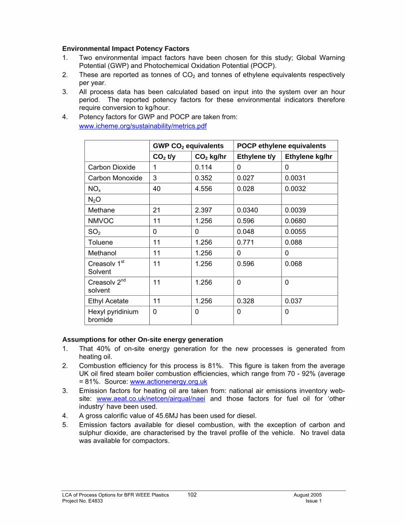
LCA of Process Options for BFR WEEE Plastics 102 August 2005 Project No. E4833 Issue 1
Environmental Impact Potency Factors 1. Two environmental impact factors have been chosen for this study; Global Warning
Potential (GWP) and Photochemical Oxidation Potential (POCP). 2. These are reported as tonnes of CO2 and tonnes of ethylene equivalents respectively
per year. 3. All process data has been calculated based on input into the system over an hour
period. The reported potency factors for these environmental indicators therefore require conversion to kg/hour.
4. Potency factors for GWP and POCP are taken from: www.icheme.org/sustainability/metrics.pdf
GWP CO2 equivalents POCP ethylene equivalents CO2 t/y CO2 kg/hr Ethylene t/y Ethylene kg/hr
Carbon Dioxide 1 0.114 0 0 Carbon Monoxide 3 0.352 0.027 0.0031 NOx 40 4.556 0.028 0.0032 N2O Methane 21 2.397 0.0340 0.0039 NMVOC 11 1.256 0.596 0.0680 SO2 0 0 0.048 0.0055 Toluene 11 1.256 0.771 0.088 Methanol 11 1.256 0 0 Creasolv 1st Solvent
11 1.256 0.596 0.068
Creasolv 2nd solvent
11 1.256 0 0
Ethyl Acetate 11 1.256 0.328 0.037 Hexyl pyridinium bromide
0 0 0 0
Assumptions for other On-site energy generation 1. That 40% of on-site energy generation for the new processes is generated from
heating oil. 2. Combustion efficiency for this process is 81%. This figure is taken from the average
UK oil fired steam boiler combustion efficiencies, which range from 70 - 92% (average = 81%. Source: www.actionenergy.org.uk
3. Emission factors for heating oil are taken from: national air emissions inventory web-site: www.aeat.co.uk/netcen/airqual/naei and those factors for fuel oil for ‘other industry’ have been used.
4. A gross calorific value of 45.6MJ has been used for diesel. 5. Emission factors available for diesel combustion, with the exception of carbon and
sulphur dioxide, are characterised by the travel profile of the vehicle. No travel data was available for compactors.
LCA of Process Options for BFR WEEE Plastics 103 August 2005 Project No. E4833 Issue 1
Avoided Emissions: from virgin plastic production 1. Data is taken from the Eco-profiles for polymer plastics produced by APME. Eco-
profiles for HIPS, ABS and PC have been used. 2. Data for gross primary fuels and feedstock have been used for energy consumption
and feedstock process. 3. Energy consumption for fuel production and transport processes are specifically
excluded. 4. Emissions include fuel use and process operations; emission from fuel production and
transport are specifically excluded. 5. GWP weighting have been applied to the emission inventories where possible; a
weighting of 11 has been given to all non-methane VOCs groupings, where individual values are not available.
6. POCP weighting have been applied to the emission inventories where possible; averaged values for the alkanes, alcohols, ketones and alkenes have been used as a representative weighting for the hydrocarbon group and ‘other’ organics; averaged values for aromatic species have been used fro the aromatic and polycyclic hydrocarbon groupings; the aldehyde grouping used average values for individual aldehyde species.
Process specific Assumptions: LANDFILL 1. There is no available data for energy consumption at landfill sites. An average
electricity draw of 500kWh has been presumed. 2. There is no data available on transport emissions from compactor vehicles at landfill
sites. 3. A fuel consumption figure of 0.6litres diesel per m3 of landfill void filled is quoted in
‘Integrated Solid Waste Management: A life-cycle Inventory’ (2001) by McDougall, F.R, White, P.R, Franke, M. and Hindle, P and has been used.
4. Emission factors have been taken from national air emissions inventory web-site: www.aeat.co.uk/netcen/airqual/naei relating to industrial off-road transport. These have been used as there is an absence of travel related data for this activity.
Process specific Assumptions: NEW PROCESSES 1. Emission factors from fuel use for plant have been taken from the national air
emissions inventory web-site: www.aeat.co.uk/netcen/airqual/naei relating to industrial off-road transport.
2. Solvent emissions are presumed to amount to 2% of made-up solvent, minus those emissions to water.
3. A GWP of 11t/y CO2 equivalent has been used for all solvents (equivalent to VOC emissions).
4. A POCP potency factor of 0.596 t/y ethylene equivalent has been used for paraffinic hydrocarbons; this is an averaged value from alkane, alkene, ketone and alcohol species.
5. The following plastic output from the New processes has been used (provided by Axion): a. Creasolv 1275kg b. Ionic Liquid 1100kg c. Centrevap 1245kg d. Anti-solvent 1245kg
LCA of Process Options for BFR WEEE Plastics 104 August 2005 Project No. E4833 Issue 1
Process specific Assumptions: INCINERATION 1. It is presumed that incineration plants recover power only, not heat; there is no
Bromine recovery. 2. Combustion efficiency is calculated at 26%. 3. Assumes that ratio of MSW:BFR WEEE plastics is 97:3. 4. Assumes that BFR can only be incinerated alongside MSW. 5. Calorific value of WEEE plastic is 44.3MJ/kg. This is based on the average calorific
values for ABS, HIPS and PC. 6. Assumes that the calorific value of MSW is 7.06MJ/kg. This figure is taken from
‘Integrated Solid Waste Management: A life-cycle Inventory’ (2001) by McDougall, F.R, White, P.R, Franke, M. and Hindle, P and is an averaged value for UK MSW.
7. Assumes 0.23m3/ tonne waste of natural gas is required to heat up the incinerator. This figure is taken from ‘Integrated Solid Waste Management: A life-cycle Inventory’ (2001) by McDougall, F.R, White, P.R, Franke, M. and Hindle, P.
8. Emission factors are taken from national air emissions inventory web-site: www.aeat.co.uk/netcen/airqual/naei relating to MSW incineration. Emissions are currently calculated on 100% MSW, not 97%; no information on emissions from plastic combustion is available at the present time.
9. Carbon dioxide emissions are based on a stoichiometric calculation, using the carbon emission factor provided from the National Air Emission Inventory website. (Carbon emission/mol. Wt carbon (12)) x mol. Wt. CO2 (44)).
10. Assumes that power recovered generates electricity; this electricity replaces traditional means of electricity generation.
11. No allowance is made for additional or lower energy requirements of the system by incorporating a higher proportion of plastics into the stream.
Process specific Assumptions: MECHANICAL RECYCLING: separation of BFR plastics 1. Average energy draw of 500kWh is required 2. Energy consumption to process 1kg of plastic is 5632KJ. Taken from: MUNICIPAL
PLASTIC WASTE: ALTERNATIVES FOR RECYCLING WITH PROFIT by Ana C. Eulálio, Numa J. Capiati and Silvia E. Barbosa.
3. Assumes that 100% energy consumption is obtained from electricity. 4. Assumes that input into the process is 1429kg of mixed plastic waste; when sorting
efficiency and BFR plastics are discarded, it is presumed that the output of the process is 1143kg of plastic recyclate.
5. Assumes 100% of emission from the process is from energy consumption. 6. A sorting efficiency of 82% is achieved. 7. 29% of mixed plastic input is BFR plastics (mainly PS and ABS); these are discarded
as waste (Wrap study): ‘Recycling of WEEE plastic waste at PHB’ van Schijndel. P, van Kasteren, J. TU Eindhoven, Study for European Brominated Flame Retardant Industry Panel, April 2004.
8. Assumes 2% of material input is inerts / non-plastic material. 9. 100% of material is WEEE sourced plastic. 10. Assumes pre-sorting to produce a mixed plastic material.
LCA of Process Options for BFR WEEE Plastics 105 August 2005 Project No. E4833 Issue 1
APPENDIX D
QUALITIATIVE ASSESSMENT SCORES
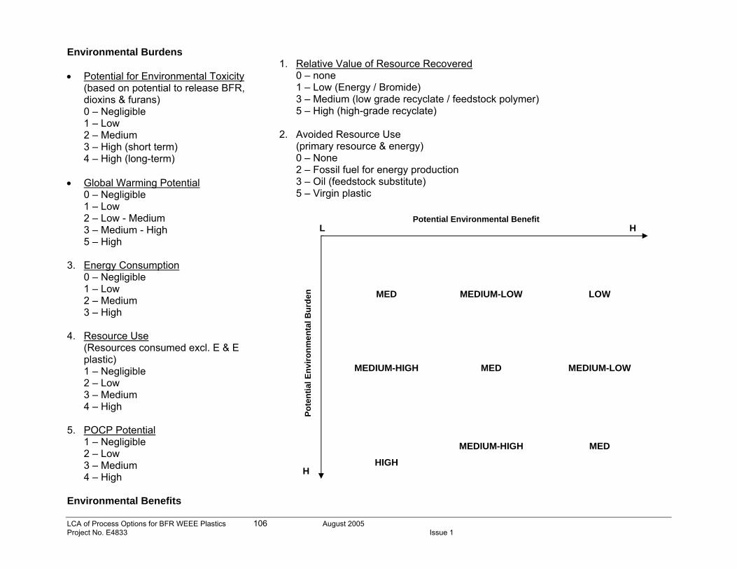
LCA of Process Options for BFR WEEE Plastics 106 August 2005 Project No. E4833 Issue 1
Environmental Burdens • Potential for Environmental Toxicity
(based on potential to release BFR, dioxins & furans) 0 – Negligible 1 – Low 2 – Medium 3 – High (short term) 4 – High (long-term)
• Global Warming Potential
0 – Negligible 1 – Low 2 – Low - Medium 3 – Medium - High 5 – High
3. Energy Consumption 0 – Negligible 1 – Low 2 – Medium 3 – High 4. Resource Use
(Resources consumed excl. E & E plastic) 1 – Negligible 2 – Low 3 – Medium 4 – High
5. POCP Potential 1 – Negligible 2 – Low 3 – Medium 4 – High
Environmental Benefits
1. Relative Value of Resource Recovered
0 – none 1 – Low (Energy / Bromide) 3 – Medium (low grade recyclate / feedstock polymer) 5 – High (high-grade recyclate)
2. Avoided Resource Use
(primary resource & energy) 0 – None 2 – Fossil fuel for energy production 3 – Oil (feedstock substitute) 5 – Virgin plastic
MED
MEDIUM-LOW
LOW
MEDIUM-HIGH
MED
MEDIUM-LOW
HIGH
MEDIUM-HIGH
MED
Potential Environmental Benefit L H
H
Pote
ntia
l Env
ironm
enta
l Bur
den
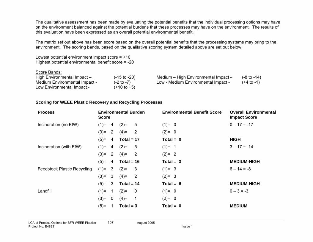
LCA of Process Options for BFR WEEE Plastics 107 August 2005 Project No. E4833 Issue 1
The qualitative assessment has been made by evaluating the potential benefits that the individual processing options may have on the environment balanced against the potential burdens that these processes may have on the environment. The results of this evaluation have been expressed as an overall potential environmental benefit. The matrix set out above has been score based on the overall potential benefits that the processing systems may bring to the environment. The scoring bands, based on the qualitative scoring system detailed above are set out below. Lowest potential environment impact score = +10 Highest potential environmental benefit score = -20 Score Bands: High Environmental Impact – (-15 to -20) Medium – High Environmental Impact - (-8 to -14) Medium Environmental Impact - (-2 to -7) Low - Medium Environmental Impact - (+4 to -1) Low Environmental Impact - (+10 to +5) Scoring for WEEE Plastic Recovery and Recycling Processes Process Environmental Burden
Score Environmental Benefit Score Overall Environmental
Impact Score Incineration (no EfW) (1)= 4 (2)= 5
(3)= 2 (4)= 2
(5)= 4 Total = 17
(1)= 0
(2)= 0
Total = 0
0 – 17 = -17
HIGH Incineration (with EfW) (1)= 4 (2)= 5
(3)= 2 (4)= 2
(5)= 4 Total = 16
(1)= 1
(2)= 2
Total = 3
3 – 17 = -14
MEDIUM-HIGH Feedstock Plastic Recycling (1)= 3 (2)= 3
(3)= 3 (4)= 2
(5)= 3 Total = 14
(1)= 3
(2)= 3
Total = 6
6 – 14 = -8
MEDIUM-HIGH Landfill (1)= 1 (2)= 0
(3)= 0 (4)= 1
(5)= 1 Total = 3
(1)= 0
(2)= 0
Total = 0
0 – 3 = -3
MEDIUM
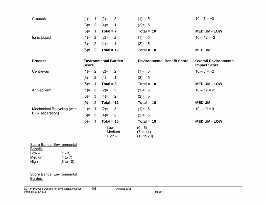
LCA of Process Options for BFR WEEE Plastics 108 August 2005 Project No. E4833 Issue 1
Creasolv (1)= 1 (2)= 2
(3)= 2 (4)= 1
(5)= 1 Total = 7
(1)= 5
(2)= 5
Total = 10
10 – 7 = +3
MEDIUM - LOW Ionic Liquid (1)= 2 (2)= 2
(3)= 2 (4)= 4
(5)= 2 Total = 12
(1)= 5
(2)= 5
Total = 10
10 – 12 = -2
MEDIUM
Process Environmental Burden
Score Environmental Benefit Score Overall Environmental
Impact Score Centrevap (1)= 2 (2)= 2
(3)= 2 (4)= 1
(5)= 1 Total = 8
(1)= 5
(2)= 5
Total = 10
10 – 8 = +2
MEDIUM - LOW Anti-solvent (1)= 2 (2)= 3
(3)= 3 (4)= 2
(5)= 2 Total = 12
(1)= 5
(2)= 5
Total = 10
10 – 12 = -2
MEDIUM Mechanical Recycling (with BFR separation)
(1)= 1 (2)= 3
(3)= 3 (4)= 2
(5)= 1 Total = 10
(1)= 5
(2)= 5
Total = 10
10 – 10 = 0
MEDIUM - LOW Score Bands: Environmental Benefit: Low – (1 - 3) Medium (4 to 7) High - (8 to 10) Score Bands: Environmental Burden:
Low – (0 - 6) Medium (7 to 14) High - (15 to 20)
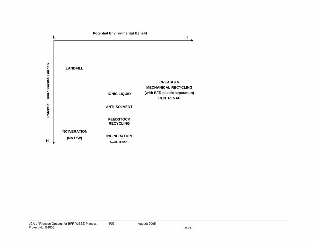
LCA of Process Options for BFR WEEE Plastics 109 August 2005 Project No. E4833 Issue 1
LANDFILL
IONIC LIQUID
ANTI-SOLVENT
CREASOLV
MECHANICAL RECYCLING (with BFR plastic separation)
CENTREVAP
INCINERATION
(No EfW)
FEEDSTOCK RECYCLING
INCINERATION
(with EfW))
Potential Environmental Benefit L H
H
Pote
ntia
l Env
ironm
enta
l Bur
den
LCA of Process Options for BFR WEEE Plastics 110 August 2005 Project No. E4833 Issue 1
Justification for Process Scores: 1. Potential for Environmental Toxicity
These scores were based on the potential of the system, primarily, to release BFR or furans. The highest scores were allocated to incineration technologies, as without the use of sophisticated scrubber systems, the potential to create furan and dioxins is high. Heating and extrusion processes in feedstock and mechanical recycling of plastics with a BFR content are presumed to release some BRFs, although mechanical recycling of WEEE plastics from which BFR plastics have already been separated are presumed to release negligible volumes of BFR or dioxins. Ionic Liquid, Centrevap and Anti-solvent processes are also presumed to release BFRs. In addition to this, some weighting has also been given to the use of toluene in these processes, which has a potential toxicology effect. Creasolv does not use toluene and is therefore weighted accordingly. It is also presumed that some BRF will be released from WEEE sent to landfill, although over a longer time scale than other processes.
2. Global Warming Potential and Energy Consumption Global warming potentials for these processes has been evaluated as being primarily linked to energy consumption for all processes but incineration processes, for which higher values are expected associated with the combustion of the WEEE plastic. These scores were weighted primarily on the amounts of energy consumed in each process and therefore the potential release of CO2 into the atmosphere. Again, incineration technologies that require the direct combustion of the material through the process are scored the highest, followed by feedstock recycling process. Energy consumption for feedstock processes is expected to be largely met by the processes itself; it is able to generate the major of it’s energy consumption needs, however, CO2 emissions will be associated with these thermal processes and as such, it has been weighted below incineration processes, but above mechanical processes and the new solvent processes. Initial data on energy consumption data from the new solvent processes indicates that the Anti-solvent process consumes more energy than the other solvents processes and this has been weighted according and comparable to mechanical recycling processes. Centrevap, Ionic Liquid and Creasolv processes all use comparable amounts of energy and been assessed comparatively. Landfill is presumed to have a negligible GWP associated only with compaction vehicles operating on site. Background energy consumption processes are excluded from the system boundary.
3. Resource Use This is presumed to include resources such as solvents, scrubbers, filters, etc. that are lost from the system as waste and /or emissions. The use of comparatively more complex scrubber systems in incineration processes with EfW is perceived to be a higher potential resource use than other incineration processes and has been scored accordingly. Feedstock recycling processes have been rated similar to incineration processes although insufficient information is available at the present time to justify this rating. Similarly, treatment processes in mechanical recycling that separate out BFR-containing plastics prior to recycling may require more resources than non-separating processes and this is reflected accordingly. Ionic liquid has the greatest solvent loss for the system of any of the new treatment processes considered and this is reflected in the higher scores given to this process; creasolv and centrifuge / evaporate are perceived to produce similar
LCA of Process Options for BFR WEEE Plastics 111 August 2005 Project No. E4833 Issue 1
volumes of waste are rated as showing the lowest resource use between the new recycling processes. Landfill is presumed to utilise negligible additional resources, excluding landfill linings and capping materials.
4. POCP Potential
This indicator has been linked primarily to the use of solvents in the treatment processes and release of VOC species through thermal treatment processes. Landfill and mechanical recycling processes are presumed to have a negligible POCP value and are scored the lowest. Incineration and feedstock processes, while not utilising solvents do utilise thermal processes and it is presumed that these will be responsible for the release of some VOC species. The potential for release of VOC’s from new plastic processes have been rated based on sources of release identified; waste drum filling, extraction, evaporation and vacuum stripping, the remediation measures put in place to minimise these emissions and the volumes of solvents used. The Ionic liquid process uses the largest volume of solvents and has been weighted with the highest POCP score of the new processes alongside Anti-solvent, which demonstrated the highest energy consumption of the solvent processes and therefore has a high potential for VOC formation. Solvent reclamation processes are visible in the process flow sheets for Creasolv and Centrevap processes and it is considered that these are effective in recovering solvent throughput and minimising the release of VOC emissions to the environment. These have been scored as presenting minimal POCP’s.

112
Appendix 5B – Explanation of QWERTY life cycle analysis
o Starting point This Chapter is written in order to provide some background information on the ideas and reasons behind QWERTY analysis and to illustrate the way of working: Product recyclability has mostly been calculated on a weight basis only, which is a poor yardstick from an environmental perspective and scientifically very inaccurate. It can lead to incorrect conclusions regarding initial environmental goals of take-back legislation. Calculations based on weight-based recyclability are likely to lead to incorrect decisions, especially when materials are present in low amounts, but with high environmental and economic values like precious metals in cellular phones. This notion has led to the development of the QWERTY concept for calculating product recyclability on a real environmental basis. The European take-back legislation for the electronics industry, the so-called WEEE Directive is primarily set up out of environmental motives13. The description of treatment performance and evaluation of recyclability targets, should therefore also take place in environmental terms. Currently this is only the case in a very limited way. In contrast to traditional Life-Cycle Assessment (LCA)14 15, QWERTY analysis starts at the point of disposal. From here, the key question is to find out which end-of-life scenarios are preferable. As a consequence of this reasoning, usually environmental burdens appear for incineration and landfill scenarios and environmental gains appear, due to preventing new material extraction for recycling scenarios. In more detail, QWERTY calculations are based on three values as illustrated in Figure 1.
13 Commission of the European Communities, Directive 2002/96/EC of the European Parliament and of the Council on waste electrical and electronic equipment (WEEE), Official Journal of the European Union, Brussels, February 13, 2003 14 M. Goedkoop, R. Spriensma, The Eco Indicator '99, a damage-oriented method for Life Cycle Impact Assessment. Final Report, National Reuse of Waste Research Program. Pré Consultants, Amersfoort, The Netherlands 15 R. Spriensma, C. Alvarado, M. Goedkoop, LCA soldering materials, Report for Philips and Alpha Fry Technology, Amersfoort, February 2002
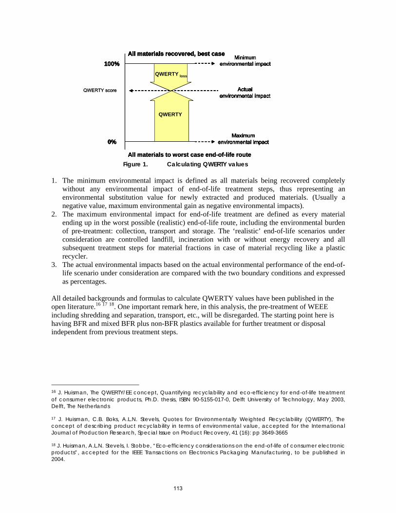
113
All materials recovered, best case
All materials to worst case end-of-life route
100%
0%
Minimum environmental impact
Actual environmental impact
Maximum environmental impact
QWERTY
QWERTY loss
All materials recovered, best case 100%
0%
Minimum environmental impact
Actual environmental impact
Maximum environmental impact
QWERTY
QWERTY loss
QWERTY score
All materials recovered, best case
All materials to worst case end-of-life route
100%
0%
Minimum environmental impact
Actual environmental impact
Maximum environmental impact
QWERTY
QWERTY loss
All materials recovered, best case 100%
0%
Minimum environmental impact
Actual environmental impact
Maximum environmental impact
QWERTY
QWERTY loss
QWERTY score
Figure 1. Calculating QWERTY values
1. The minimum environmental impact is defined as all materials being recovered completely
without any environmental impact of end-of-life treatment steps, thus representing an environmental substitution value for newly extracted and produced materials. (Usually a negative value, maximum environmental gain as negative environmental impacts).
2. The maximum environmental impact for end-of-life treatment are defined as every material ending up in the worst possible (realistic) end-of-life route, including the environmental burden of pre-treatment: collection, transport and storage. The ‘realistic’ end-of-life scenarios under consideration are controlled landfill, incineration with or without energy recovery and all subsequent treatment steps for material fractions in case of material recycling like a plastic recycler.
3. The actual environmental impacts based on the actual environmental performance of the end-of-life scenario under consideration are compared with the two boundary conditions and expressed as percentages.
All detailed backgrounds and formulas to calculate QWERTY values have been published in the open literature.16 17 18. One important remark here, in this analysis, the pre-treatment of WEEE including shredding and separation, transport, etc., will be disregarded. The starting point here is having BFR and mixed BFR plus non-BFR plastics available for further treatment or disposal independent from previous treatment steps.
16 J. Huisman, The QWERTY/EE concept, Quantifying recyclability and eco-efficiency for end-of-life treatment of consumer electronic products, Ph.D. thesis, ISBN 90-5155-017-0, Delft University of Technology, May 2003, Delft, The Netherlands 17 J. Huisman, C.B. Boks, A.L.N. Stevels, Quotes for Environmentally Weighted Recyclability (QWERTY), The concept of describing product recyclability in terms of environmental value, accepted for the International Journal of Production Research, Special Issue on Product Recovery, 41 (16): pp 3649-3665 18 J. Huisman, A.L.N. Stevels, I. Stobbe, “Eco-efficiency considerations on the end-of-life of consumer electronic products”, accepted for the IEEE Transactions on Electronics Packaging Manufacturing, to be published in 2004.
114
o QWERTY: Environmental values The QWERTY calculations require ‘environmental values’. These values can be derived from any comprehensive environmental assessment model that provides such scores, but also from methods focusing on a single environmental effect, like for instance, eco-toxicity or resource depletion, can be used. The default method applied for this research is the Eco-Indicator ’99 method, a damage oriented LCA-method19. The approach is also called a top-down LCA-method since all contributions to all environmental effects are translated to actual damage inflicted to eco-system quality, human health and resource depletion. Results will be checked by presenting the results also under grouped individual environmental themes rather than single indicators to determine to influence of the choice of the environmental assessment model. In addition to the default choice, also other methods are integrated in the QWERTY calculations to evaluate the environmental outcomes. It is also possible to evaluate on single environmental themes, like for instance on climate change effect. With this the disadvantages of applying a final weighting step as enumerated below are reduced, but it limits the transparency and relevance of results to single environmental themes only. In this report the results will also be displayed under these individual impact categories. Further considerations with respect to the use of LCA methods and methodologies for providing environmental values are: 1. In LCA there is always a ‘subjective’ evaluation step involved to weigh different environmental
themes and to produce a single end-point score. This is inherent to aggregated environmental scores of any kind. One reason for choosing the Eco-Indicator ’99 is that, compared to other LCA methods, it is the most transparent one regarding influence of different environmental perspectives and opinions of all factors that influence the final end-point score (and not only the final weighting step).
2. Again, the starting point of the QWERTY concept is not the same compared to LCA. The QWERTY analysis starts at the point of disposal till the ‘end of the end-of-life’ phase, while LCA methods regard the full life-cycle of products, hence different system boundaries and allocation rules apply. Due to this different starting point, the QWERTY concept regards materials that are recycled as preventing extra environmental load (so negative values appear for recycled materials) due to new raw material extraction or energy production. Due to this choice, many problems with allocation and the definition of system boundaries are prevented.
3. An important requirement is an environmental database providing environmental values for all relevant end-of-life processing steps and materials. For all relevant processing of materials, the mass and energy balances must be transferred to corresponding environmental values. Especially for the end-of-life phase of products, there are usually many data gaps within current LCA-databases. However, with the existing QWERTY calculations all relevant materials and processing steps have good quality inventories as the background data.
19 M. Goedkoop, R. Spriensma, The Eco Indicator '99, a damage-oriented method for Life Cycle Impact Assessment. Final Report, National Reuse of Waste Research Program. Pré Consultants, Amersfoort, The Netherlands
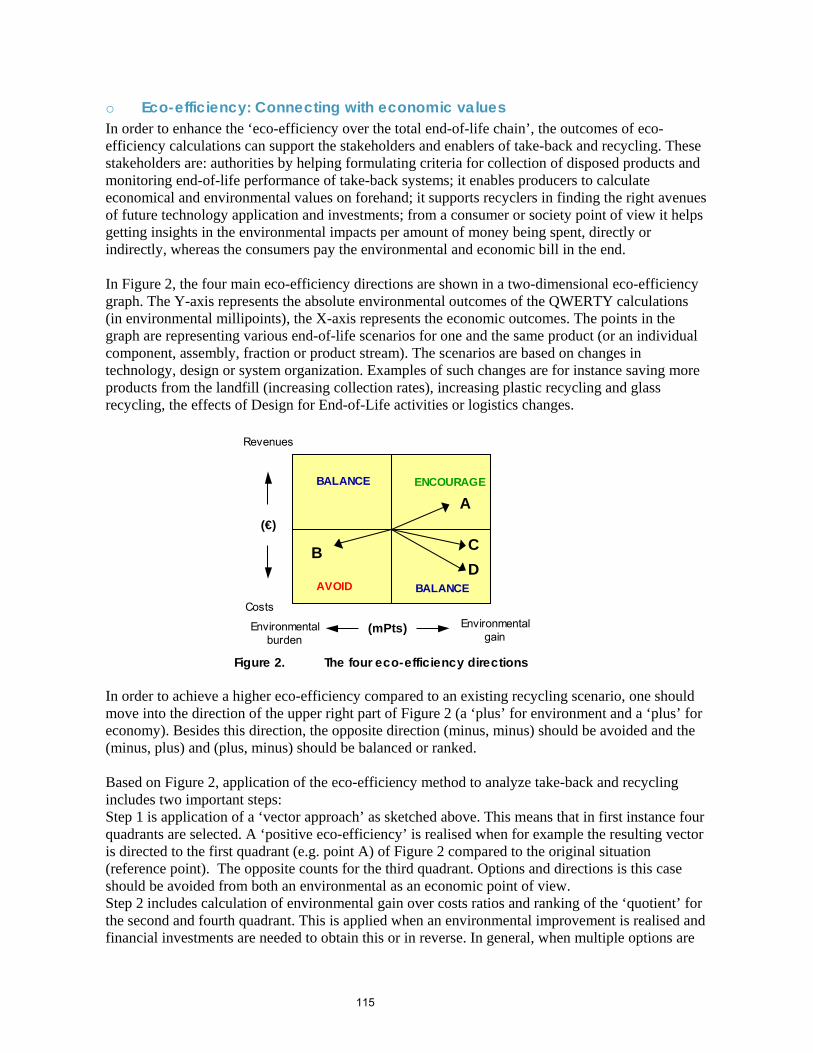
115
o Eco-efficiency: Connecting with economic values In order to enhance the ‘eco-efficiency over the total end-of-life chain’, the outcomes of eco-efficiency calculations can support the stakeholders and enablers of take-back and recycling. These stakeholders are: authorities by helping formulating criteria for collection of disposed products and monitoring end-of-life performance of take-back systems; it enables producers to calculate economical and environmental values on forehand; it supports recyclers in finding the right avenues of future technology application and investments; from a consumer or society point of view it helps getting insights in the environmental impacts per amount of money being spent, directly or indirectly, whereas the consumers pay the environmental and economic bill in the end. In Figure 2, the four main eco-efficiency directions are shown in a two-dimensional eco-efficiency graph. The Y-axis represents the absolute environmental outcomes of the QWERTY calculations (in environmental millipoints), the X-axis represents the economic outcomes. The points in the graph are representing various end-of-life scenarios for one and the same product (or an individual component, assembly, fraction or product stream). The scenarios are based on changes in technology, design or system organization. Examples of such changes are for instance saving more products from the landfill (increasing collection rates), increasing plastic recycling and glass recycling, the effects of Design for End-of-Life activities or logistics changes.
Environmental gain
(€)
Costs
Environmental burden
(mPts)
Revenues
ENCOURAGE
AVOID
A
B CD
BALANCE
BALANCE
Figure 2. The four eco-efficiency directions
In order to achieve a higher eco-efficiency compared to an existing recycling scenario, one should move into the direction of the upper right part of Figure 2 (a ‘plus’ for environment and a ‘plus’ for economy). Besides this direction, the opposite direction (minus, minus) should be avoided and the (minus, plus) and (plus, minus) should be balanced or ranked. Based on Figure 2, application of the eco-efficiency method to analyze take-back and recycling includes two important steps: Step 1 is application of a ‘vector approach’ as sketched above. This means that in first instance four quadrants are selected. A ‘positive eco-efficiency’ is realised when for example the resulting vector is directed to the first quadrant (e.g. point A) of Figure 2 compared to the original situation (reference point). The opposite counts for the third quadrant. Options and directions is this case should be avoided from both an environmental as an economic point of view. Step 2 includes calculation of environmental gain over costs ratios and ranking of the ‘quotient’ for the second and fourth quadrant. This is applied when an environmental improvement is realised and financial investments are needed to obtain this or in reverse. In general, when multiple options are
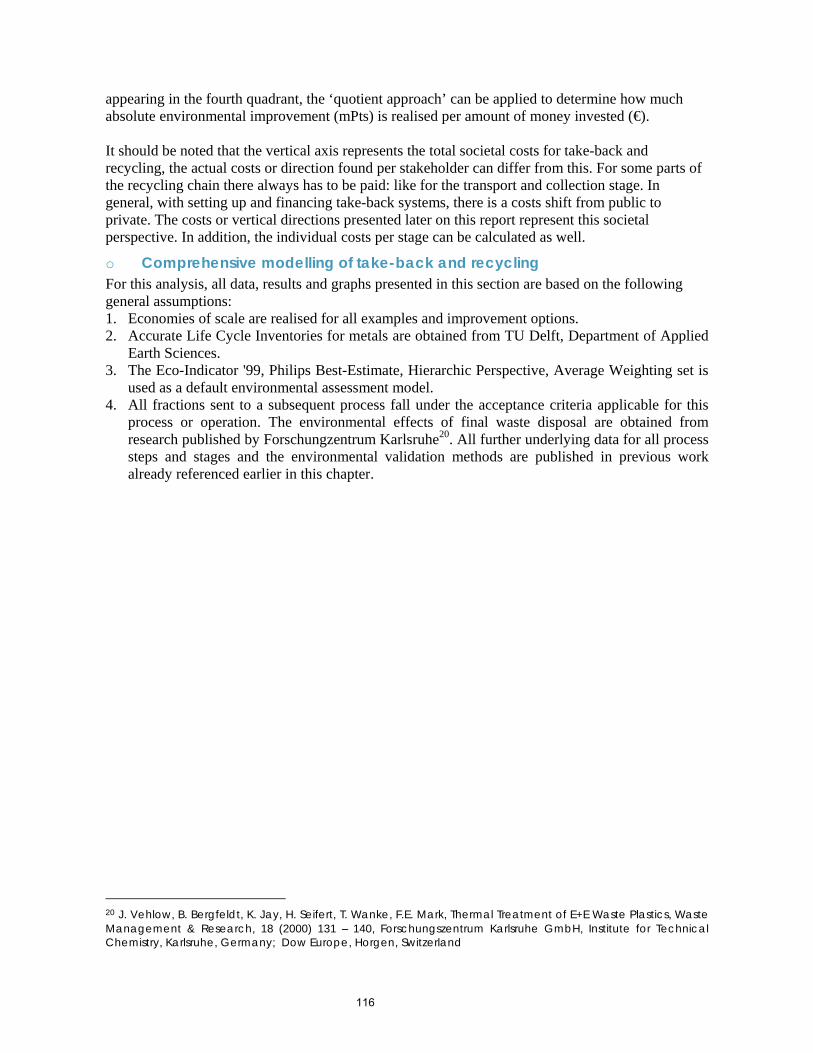
116
appearing in the fourth quadrant, the ‘quotient approach’ can be applied to determine how much absolute environmental improvement (mPts) is realised per amount of money invested (€). It should be noted that the vertical axis represents the total societal costs for take-back and recycling, the actual costs or direction found per stakeholder can differ from this. For some parts of the recycling chain there always has to be paid: like for the transport and collection stage. In general, with setting up and financing take-back systems, there is a costs shift from public to private. The costs or vertical directions presented later on this report represent this societal perspective. In addition, the individual costs per stage can be calculated as well.
o Comprehensive modelling of take-back and recycling For this analysis, all data, results and graphs presented in this section are based on the following general assumptions: 1. Economies of scale are realised for all examples and improvement options. 2. Accurate Life Cycle Inventories for metals are obtained from TU Delft, Department of Applied
Earth Sciences. 3. The Eco-Indicator '99, Philips Best-Estimate, Hierarchic Perspective, Average Weighting set is
used as a default environmental assessment model. 4. All fractions sent to a subsequent process fall under the acceptance criteria applicable for this
process or operation. The environmental effects of final waste disposal are obtained from research published by Forschungzentrum Karlsruhe20. All further underlying data for all process steps and stages and the environmental validation methods are published in previous work already referenced earlier in this chapter.
20 J. Vehlow, B. Bergfeldt, K. Jay, H. Seifert, T. Wanke, F.E. Mark, Thermal Treatment of E+E Waste Plastics, Waste Management & Research, 18 (2000) 131 – 140, Forschungszentrum Karlsruhe GmbH, Institute for Technical Chemistry, Karlsruhe, Germany; Dow Europe, Horgen, Switzerland
117
Appendix 5C – QWERTY analysis method for this project
• Introduction o Background This report is requested by Axion Recycling Ltd acting as project manager for The Waste and Resources Action Programme – WRAP Project on developing processes to extract brominated flame retardants from WEEE Polymers. As part of this project an environmental impact assessment and eco-efficiency evaluation is needed. It is decided not to apply a classic LCA study (Life Cycle Assessment) on BFR plastics but rather a streamlined description on what happens from an environmental and economic point of view when these plastics are obtained at processing WEEE by recyclers. The QWERTY/EE approach (Quotes for environmentally WEighted RecyclabiliTY and Eco-Efficiency)21 , is built for this purpose and quantifies the environmental and economic performance throughout the WEEE recycling chain. The approach, developed at TU Delft, resulted in comprehensive descriptions and data collection on all actors of the recycling chain of waste electronic products. As can be seen in Figure 3, the stages include product compositions, characteristics on collection and treatment including modelling of shredding and separation, final waste routes and closing material cycles through upgrading, refining. The approach applied for this report describes the environmental and economic effects of BFR and non-BFR plastics with the starting point that these plastic fractions already have become available at collection and treatment by means of shredding and separation and dismantling. In the analysis, these previous stages of the WEEE recycling chain are left out of the scope of the analysis. Therefore, the material recycling arrow and incineration/ landfill arrows of Figure 3 plus all further treatment steps are quantified.
Use
Incineration energy recovery
Collection and treatment
Incinerationno energy recovery
LandfillRe-use (2nd hand)
Upgrading
Material production Production
Refurbishment
Material recyclingRefining
Raw materialextraction
Use
Incineration energy recovery
Collection and treatment
Incinerationno energy recovery
LandfillRe-use (2nd hand)
Upgrading
Material production Production
Refurbishment
Material recyclingRefining
Raw materialextraction
Figure 3. The end-of-life chain
21 J. Huisman, C.B. Boks, A.L.N. Stevels, Quotes for Environmentally Weighted Recyclability (QWERTY), The concept of describing product recyclability in terms of environmental value, accepted for the International Journal of Production Research, Special Issue on Product Recovery, 41 (16): pp 3649-3665
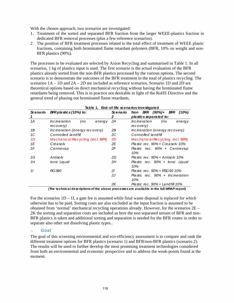
118
With the chosen approach, two scenarios are investigated: 1. Treatment of the sorted and separated BFR fraction from the larger WEEE-plastics fraction in
dedicated BFR removal processes (plus a few reference scenarios). 2. The position of BFR treatment processes related to the total effect of treatment of WEEE plastic
fractions, containing both brominated flame retardant polymers (BFR, 10% on weight and non-BFR plastics (90%).
The processes to be evaluated are selected by Axion Recycling and summarised in Table 1. In all scenarios, 1 kg of plastics input is used. The first scenario is the actual evaluation of the BFR plastics already sorted from the non-BFR plastics processed by the various options. The second scenario is to demonstrate the outcomes of the BFR treatment in the total of plastics recycling. The scenarios 1A – 1D and 2A – 2D are included as reference scenarios. Scenario 1D and 2D are theoretical options based on direct mechanical recycling without having the brominated flame retardants being removed. This is in practice not desirable in light of the RoHS Directive and the general trend of phasing out brominated flame retardants.
Table 1. End-of-life scenarios investigated Scenario 1
BFR plastics (10%) to: Scenario 2
Non BFR (90%)+ BFR (10%) plastics separated to:
1A Incineration (no energy recovery)
2A Incineration (no energy recovery)
1B Incineration (energy recovery) 2B Incineration (energy recovery) 1C Controlled landfill 2C Controlled landfill 1D Mechanical Recycling (incl. BFR) 2D Mechanical Recycling incl. BFR) 1E Creasolv 2E Plastic rec. 90% + Creasolv 10% 1F Centrevap 2F Plastic rec. 90% + Centrevap
10% 1G Antisolv 2G Plastic rec. 90% + Antisolv 10% 1H Ionic Liquid 2H Plastic rec. 90% + Ionic Liquid
10% 1I RGS90 2I Plastic rec. 90% + RSG90 10% 2J Plastic rec. 90% + Incineration
10% 2K Plastic rec. 90% + Landfill 10%
(The technical descriptions of the above processes are available in the full WRAP report) For the scenarios 1D – 1I, a gate fee is assumed while final waste disposal is replaced for which otherwise has to be paid. Sorting costs are also excluded as the input fraction is assumed to be obtained from ‘normal’ mechanical recycling operations already. However, for the scenarios 2E – 2K the sorting and separation costs are included as here the non separated stream of BFR and non-BFR plastics is taken and additional sorting and separation is needed for the BFR routes in order to separate also other not dissolving plastic types..
o Goal The goal of this screening environmental and eco-efficiency assessment is to compare and rank the different treatment options for BFR plastics (scenario 1) and BFR/non-BFR plastics (scenario 2). The results will be used to further develop the most promising treatment technologies considered from both an environmental and economic perspective and to address the weak-points found at the moment.
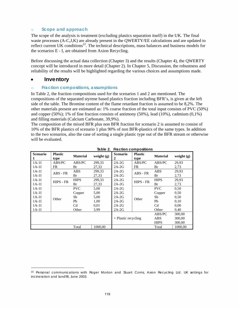
119
o Scope and approach The scope of the analysis is treatment (excluding plastics separation itself) in the UK. The final waste processes (A-C,J,K) are already present in the QWERTY/EE calculations and are updated to reflect current UK conditions22. The technical descriptions, mass balances and business models for the scenarios E - I, are obtained from Axion Recycling. Before discussing the actual data collection (Chapter 3) and the results (Chapter 4), the QWERTY concept will be introduced in more detail (Chapter 2). In Chapter 5, Discussion, the robustness and reliability of the results will be highlighted regarding the various choices and assumptions made.
• Inventory o Fraction compositions, assumptions In Table 2, the fraction compositions used for the scenarios 1 and 2 are mentioned. The compositions of the separated styrene based plastics fraction including BFR’s, is given at the left side of the table. The Bromine content of the flame retardant fraction is assumed to be 8,2%. The other materials present are estimated as: 1% coarse fraction of the total input consists of PVC (50%) and copper (50%); 1% of fine fraction consists of antimony (50%), lead (10%), cadmium (0,1%) and filling materials (Calcium Carbonate, 39,9%). The composition of the mixed BFR plus non BFR fraction for scenario 2 is assumed to consist of 10% of the BFR plastics of scenario 1 plus 90% of non BFR-plastics of the same types. In addition to the two scenarios, also the case of sorting a single plastic type out of the BFR stream or otherwise will be evaluated.
Table 2. Fraction compositions Scenario 1
Plastic type Material weight (g) Scenario
2 Plastic type Material weight (g)
1A-1I ABS/PC 299,33 2A-2G ABS/PC 29,93 1A-1I
ABS/PC FR Br 27,33 2A-2G
ABS/PC FR Br 2,73
1A-1I ABS 299,33 2A-2G ABS 29,93 1A-1I ABS - FR Br 27,33 2A-2G ABS - FR Br 2,73 1A-1I HIPS 299,33 2A-2G HIPS 29,93 1A-1I HIPS - FR Br 27,33 2A-2G HIPS - FR Br 2,73 1A-1I PVC 5,00 2A-2G PVC 0,50 1A-1I Copper 5,00 2A-2G Copper 0,50 1A-1I Sb 5,00 2A-2G Sb 0,50 1A-1I Pb 1,00 2A-2G Pb 0,10 1A-1I Cd 0,01 2A-2G Cd 0,00 1A-1I
Other
Other 3,99 2A-2G
Other
Other 0,40 ABS/PC 300,00 ABS 300,00
+ Plastic recycling HIPS 300,00
Total 1000,00 Total 1000,00
22 Personal communications with Roger Morton and Stuart Corns, Axion Recycling Ltd. UK settings for incineration and landfill, June 2003.
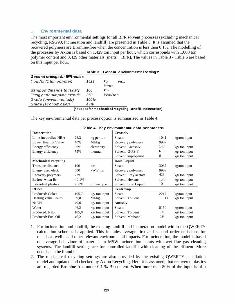
120
o Environmental data The most important environmental settings for all BFR solvent processes (excluding mechanical recycling, RSG90, Incineration and landfill) are presented in Table 3. It is assumed that the recovered polymers are Bromine-free when the concentration is less then 0,1%. The modelling of the processes by Axion is based on 1,429 ton input per hour, which corresponds with 1,000 ton polymer content and 0,429 other materials (inerts + BFR). The values in Table 3 - Table 6 are based on this input per hour.
Table 3. General environmental settings* General settings for BFR routes Input/hr (1 ton polymer) 1429 kg incl.
inerts Transport distance to facility 100 km Energy consumption electric 350 kWh/ton Grade (environmentally) 100% Grade (economically) 47%
(*except for mechanical recycling, landfill, incineration) The key environmental data per process option is summarised in Table 4.
Table 4. Key environmental data per process Incineration Creasolv Lime (neutralize HBr) 28,3 kg per ton Steam 1041 kg/ton input Lower Heating Value 40% MJ/kg Recovery polymers 99% Energy efficiency 26% electricity Solvent: Creasolv 14,4 kg/ ton input Energy efficiency 75% thermal Solvent: G-PS-F 6 kg/ ton input Solvent Isopropanol 0 kg/ ton input Mechanical recycling Ionic Liquid Transport distance 100 km Steam 3037 kg/ton input Energy used elect. 500 kWh/ ton Recovery polymers 99% Recovery polymers 77% Solvent: Ethylacetate 423 kg/ ton input Br free' when Br <0,1% Solvent: Hexane 1,25 kg/ ton input Individual plastics >80% of one type Solvent Ionic Liquid 10 kg/ ton input RGS90 Centrevap Produced: Cokes 105,7 kg/ ton input Steam 2217 kg/ton input Heating value Cokes 59,8 MJ/kg Solvent: Toluene 11 kg/ ton input NaOH 40,6 kg/ ton input Antisolv Water 46,2 kg/ ton input Steam 8150 kg/ton input Produced: NaBr 105,0 kg/ ton input Solvent: Toluene 14 kg/ ton input Produced: Fuel Oil 46,2 kg/ ton input Solvent: Methanol 19 kg/ ton input
1. For incineration and landfill, the existing landfill and incineration model within the QWERTY
calculation schemes is applied. This includes average first and second order emissions for metals as well as all other relevant environmental impacts. For incineration, the model is based on average behaviour of materials in MSW incineration plants with wet flue gas cleaning systems. The landfill settings are for controlled landfill with cleaning of the effluent. More details can be found in.
2. The mechanical recycling settings are also provided by the existing QWERTY calculation model and updated and checked by Axion Recycling. Here it is assumed, that recovered plastics are regarded Bromine free under 0,1 % Br content. When more than 80% of the input is of a
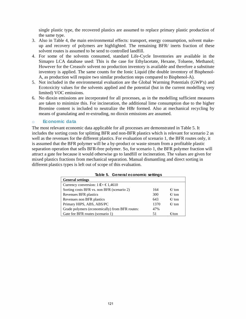
121
single plastic type, the recovered plastics are assumed to replace primary plastic production of the same type.
3. Also in Table 4, the main environmental effects: transport, energy consumption, solvent make-up and recovery of polymers are highlighted. The remaining BFR/ inerts fraction of these solvent routes is assumed to be send to controlled landfill.
4. For some of the solvents consumed, standard Life-Cycle Inventories are available in the Simapro LCA database used: This is the case for Ethylacetate, Hexane, Toluene, Methanol; However for the Creasolv solvent no production inventory is available and therefore a substitute inventory is applied. The same counts for the Ionic Liquid (the double inventory of Bisphenol-A, as production will require two similar production steps compared to Bisphenol-A).
5. Not included in the environmental evaluation are the Global Warming Potentials (GWP's) and Ecotoxicity values for the solvents applied and the potential (but in the current modelling very limited) VOC emissions.
6. No dioxin emissions are incorporated for all processes, as in the modelling sufficient measures are taken to minimize this. For incineration, the additional lime consumption due to the higher Bromine content is included to neutralize the HBr formed. Also at mechanical recycling by means of granulating and re-extruding, no dioxin emissions are assumed.
o Economic data The most relevant economic data applicable for all processes are demonstrated in Table 5. It includes the sorting costs for splitting BFR and non-BFR plastics which is relevant for scenario 2 as well as the revenues for the different plastics. For evaluation of scenario 1, the BFR routes only, it is assumed that the BFR polymer will be a by-product or waste stream from a profitable plastic separation operation that sells BFR-free polymer. So, for scenario 1, the BFR polymer fraction will attract a gate fee because it would otherwise go to landfill or incineration. The values are given for mixed plastics fractions from mechanical separation. Manual dismantling and direct sorting in different plastics types is left out of scope of this evaluation.
Table 5. General economic settings General settings Currency conversion: 1 ₤= € 1,4610 Sorting costs BFR vs. non BFR (scenario 2) 164 €/ ton Revenues BFR plastics 300 €/ ton Revenues non BFR plastics 643 €/ ton Primary HIPS, ABS, ABS/PC 1370 €/ ton Grade polymers (economically) from BFR routes: 47% Gate fee BFR routes (scenario 1) 51 €/ton
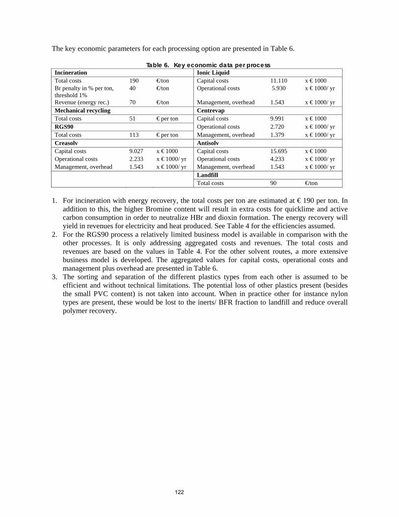
122
The key economic parameters for each processing option are presented in Table 6.
Table 6. Key economic data per process Incineration Ionic Liquid Total costs 190 €/ton Capital costs 11.110 x € 1000 Br penalty in % per ton, threshold 1%
40 €/ton Operational costs 5.930 x € 1000/ yr
Revenue (energy rec.) 70 €/ton Management, overhead 1.543 x € 1000/ yr Mechanical recycling Centrevap Total costs 51 € per ton Capital costs 9.991 x € 1000 RGS90 Operational costs 2.720 x € 1000/ yr Total costs 113 € per ton Management, overhead 1.379 x € 1000/ yr Creasolv Antisolv Capital costs 9.027 x € 1000 Capital costs 15.695 x € 1000 Operational costs 2.233 x € 1000/ yr Operational costs 4.233 x € 1000/ yr Management, overhead 1.543 x € 1000/ yr Management, overhead 1.543 x € 1000/ yr Landfill Total costs 90 €/ton
1. For incineration with energy recovery, the total costs per ton are estimated at € 190 per ton. In
addition to this, the higher Bromine content will result in extra costs for quicklime and active carbon consumption in order to neutralize HBr and dioxin formation. The energy recovery will yield in revenues for electricity and heat produced. See Table 4 for the efficiencies assumed.
2. For the RGS90 process a relatively limited business model is available in comparison with the other processes. It is only addressing aggregated costs and revenues. The total costs and revenues are based on the values in Table 4. For the other solvent routes, a more extensive business model is developed. The aggregated values for capital costs, operational costs and management plus overhead are presented in Table 6.
3. The sorting and separation of the different plastics types from each other is assumed to be efficient and without technical limitations. The potential loss of other plastics present (besides the small PVC content) is not taken into account. When in practice other for instance nylon types are present, these would be lost to the inerts/ BFR fraction to landfill and reduce overall polymer recovery.
123
• Results o Main results scenario 1 The main results of scenario 1 for the routes for treatment of the BFR plastics are summarised in Table 7. The third column shows the mPts (millipoints) outcomes as single indicator values based on the Eco-Indicator'99 LCA methodology. A negative sign means avoided environmental burden (environmental gain) and/ or costs (revenues).
Table 7. Main results BFR plastics routes Scenario QWERTY mPts € 1A. Incineration (no energy recovery) 26,6% 24,1 0,17 1B. Incineration (energy recovery) 38,3% -9,0 0,16 1C. Controlled landfill 31,6% 1,4 0,12 1D. Mechanical Recycling (100%, incl. BFR) 87,3% -251,9 -0,21 1E. Creasolv 93,2% -278,9 -0,29 1F. Centrevap 87,1% -251,0 -0,26 1G. Antisolv 68,8% -167,9 -0,11 1H. Ionic Liquid 73,7% -190,3 0,04 1I. RGS90 45,9% -63,4 0,04 From the table is can be concluded that the 1E. Creasolv and 1F. Centrevap options are the most preferable from an environmental perspective. Again note that the 1D. Mechanical Recycling scenario is added as a reference. With this scenario, the BFR is not removed but remains within the polymer product. The 1G. Antisolv and 1H. Ionic Liquid options seem to have a lower scoring followed by the two thermal scenarios 1I. RGS90 and 1B. Incineration with energy recovery. The least preferable options are 1C. Controlled Landfill and 1A. Incineration without energy recovery.
o QWERTY scores: environmental ranking scenario 1 The absolute environmental values (mPts) of Table 7 can also be displayed as relative values with QWERTY scores. Note that the QWERTY scores are based on the two boundary conditions of recovery of all materials without any environmental burden (100%) and the maximum burden per materials over all relevant processes, including energy consumption, transport and loss of materials (0%). Also, the environmental impacts of the collection, transport and shredding and separation steps prior to the BFR treatment options are not included. These choices make that the some of the actual scenarios of Table 4 are 100% best case condition. It should be noticed that all environmental burden of previous processing steps are not included here.
124
0% 20% 40% 60% 80% 100%
1E. Creasolv
1D. Mechanical Recycling (100%, incl. BFR)
1F. Centrevap
1H. Ionic Liquid
1G. Antisolv
1I. RSG90
1B. Incineration (energy recovery)
1C. Controlled landfill
1A. Incineration (no energy recovery)
Figure 4 QWERTY scores for BFR plastics processing routes - scenario 1
Again, in line with Table 7, the graph shows the distinction between the 1E. Creasolv and 1F. Centrevap processes versus 1H. Ionic Liquid and 1F. Antisolv versus the thermal processes 1I. RSG90 and 1B. Incineration with energy recovery. Obviously, the lower solvent and energy consumption of 1E. Creasolv and 1F. Centrevap from Table 4 compared to the other solvent routes leads to the much higher environmental performance. The same effect is visible in the economic outcomes. Whereas the recoveries are comparable, the lower energy and solvent consumption also leads to less costs and higher overall performance:
125
o Eco-efficiency diagram scenario 1
-€ 0.40
-€ 0.30
-€ 0.20
-€ 0.10
€ 0.00
€ 0.10
€ 0.20
-300-250-200-150-100-50050
1A. Incineration (no energyrecovery)1B. Incineration (energyrecovery)1C. Controlled landfill
1D. Mechanical Recycling(100%, incl. BFR)1E. Creasolv
1F. Centrevap
1G. Antisolv
1H. Ionic Liquid
Revenues
(€)
Costs
Environmental loss (mPts) Environmental gain
1
1C
1
1D
1E
1F
1G
1H1I
Figure 5 Eco-efficiency diagram for Scenario 1 (based on Table 7) The eco-efficiency graph also shows the 1E. Creasolv and 1F. Centrevap process in the preferred upper right part of the graph. This is due to the lowest energy and solvent consumption, the gate fee, the recovery and production of new plastics and the connected avoided environmental burden of this. It also indicates that the material recycling demonstrated with the solvent routes are to be preferred above the thermal routes 1I. RGS90 and 1B. Incineration with energy recovery. One remaining question is of course how the sorting costs for separating the BFR plastics for the main plastics fraction would influence this and what the environmental effect is of enabling the 1D. scenario of Mechanical Recycling for the other 90% of the WEEE plastics. This will be illustrated for scenario 2, but first the contribution of the various BFR treatment stages is highlighted.
126
o Contribution of stages In Figure 6, the contribution of transport, emissions, solvent and energy consumption to the environmental burden (on top) and the environmental gain due to replaced material or energy production is displayed. The bars represent the weighted single indicator according to Eco-Indicator'99. The same environmental results are demonstrated for all grouped environmental impacts (HH, Human Health, EQ, Ecosystem Quality, RD, Resource Depletion) and all individual environmental impact categories. In this graph, environmental burden is directed above, environmental gain below.
Figure 6 Contribution of stages, scenario 1
Note the relatively large environmental gain (below 0) of replacing primary materials for the solvent routes, the solvent effect of Ionic Liquid in particular and the substantial effect of the high energy consumption of the Antisolv process. For the thermal processes it can be observed that the emissions of incineration play a role as well as the connected energy recovery effect to the environmental gain. The energy recovery effect is less compared to the materials recovered for the solvent routes. The emissions of the RGS90 process are lower compared to incineration, as a result of the oil and coke production and the fact that the further thermal use of these intermediate products is outside the system boundaries as only the replacement effect of oil respectively the coal cakes production and extraction are taken into account and the excluded emissions of later thermal use.
(350,00)
(300,00)
(250,00)
(200,00)
(150,00)
(100,00)
(50,00)
-
50,00
100,00
150,00
Creasolv Plastreccopy Ionic Liquid CentrEvap Antisolv RSG90 Incineration Landfill
TransportGainEmissionsSolventsEnergy
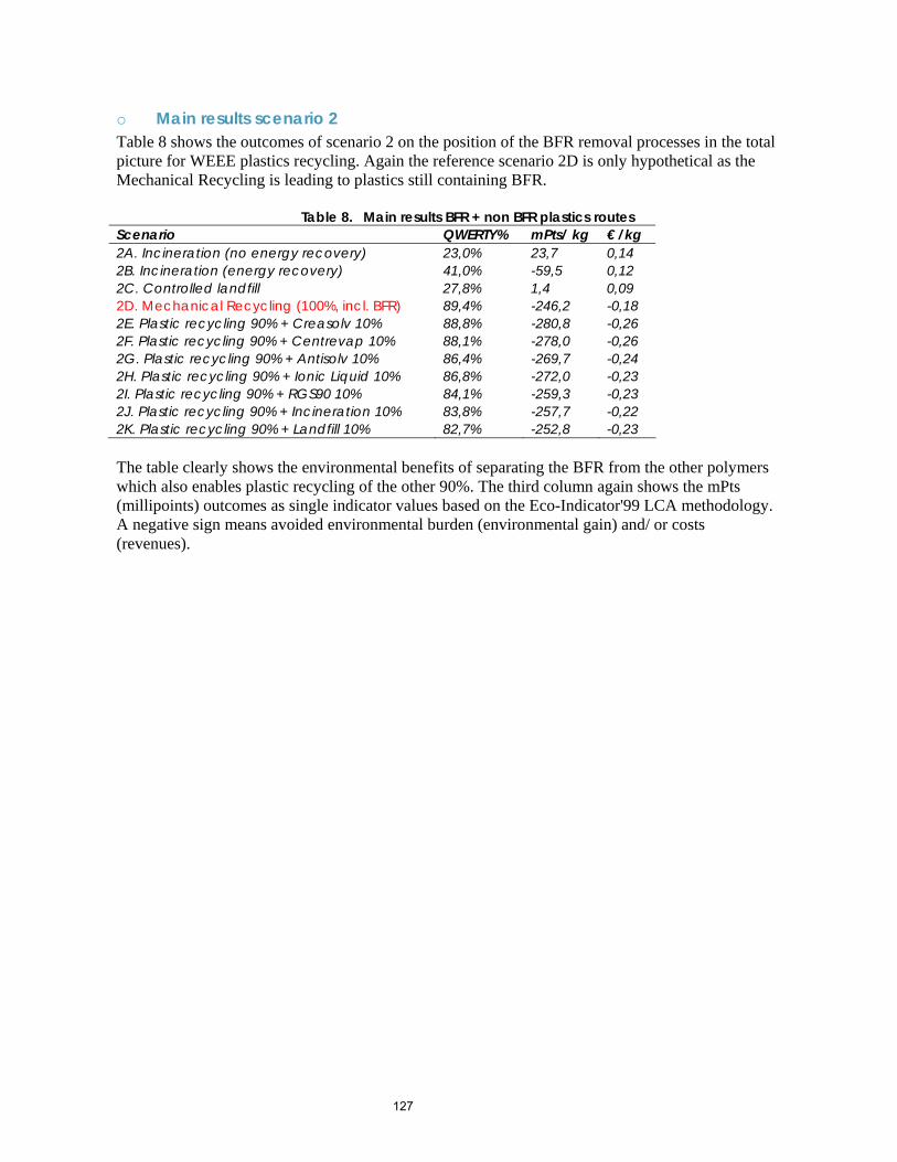
127
o Main results scenario 2 Table 8 shows the outcomes of scenario 2 on the position of the BFR removal processes in the total picture for WEEE plastics recycling. Again the reference scenario 2D is only hypothetical as the Mechanical Recycling is leading to plastics still containing BFR.
Table 8. Main results BFR + non BFR plastics routes Scenario QWERTY% mPts/ kg € /kg 2A. Incineration (no energy recovery) 23,0% 23,7 0,14 2B. Incineration (energy recovery) 41,0% -59,5 0,12 2C. Controlled landfill 27,8% 1,4 0,09 2D. Mechanical Recycling (100%, incl. BFR) 89,4% -246,2 -0,18 2E. Plastic recycling 90% + Creasolv 10% 88,8% -280,8 -0,26 2F. Plastic recycling 90% + Centrevap 10% 88,1% -278,0 -0,26 2G. Plastic recycling 90% + Antisolv 10% 86,4% -269,7 -0,24 2H. Plastic recycling 90% + Ionic Liquid 10% 86,8% -272,0 -0,23 2I. Plastic recycling 90% + RGS90 10% 84,1% -259,3 -0,23 2J. Plastic recycling 90% + Incineration 10% 83,8% -257,7 -0,22 2K. Plastic recycling 90% + Landfill 10% 82,7% -252,8 -0,23 The table clearly shows the environmental benefits of separating the BFR from the other polymers which also enables plastic recycling of the other 90%. The third column again shows the mPts (millipoints) outcomes as single indicator values based on the Eco-Indicator'99 LCA methodology. A negative sign means avoided environmental burden (environmental gain) and/ or costs (revenues).
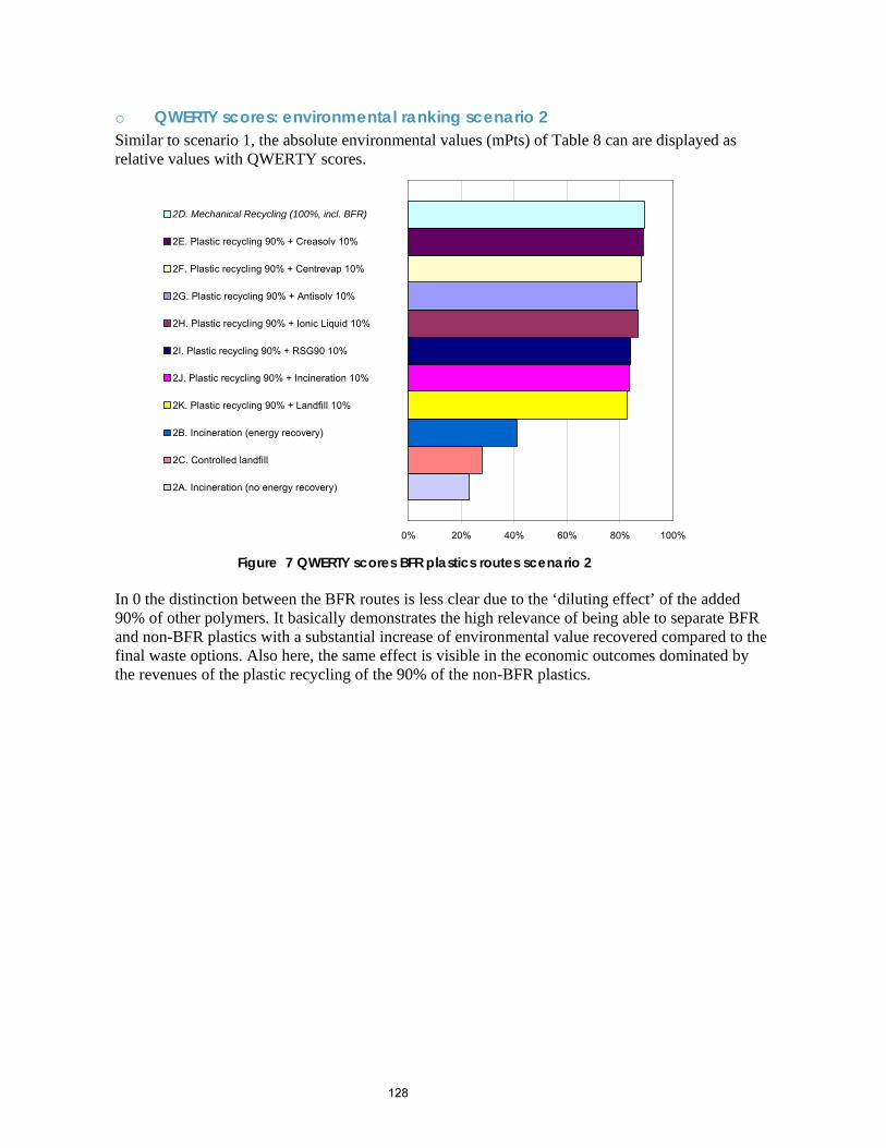
128
o QWERTY scores: environmental ranking scenario 2 Similar to scenario 1, the absolute environmental values (mPts) of Table 8 can are displayed as relative values with QWERTY scores.
0% 20% 40% 60% 80% 100%
2D. Mechanical Recycling (100%, incl. BFR)
2E. Plastic recycling 90% + Creasolv 10%
2F. Plastic recycling 90% + Centrevap 10%
2G. Plastic recycling 90% + Antisolv 10%
2H. Plastic recycling 90% + Ionic Liquid 10%
2I. Plastic recycling 90% + RSG90 10%
2J. Plastic recycling 90% + Incineration 10%
2K. Plastic recycling 90% + Landfill 10%
2B. Incineration (energy recovery)
2C. Controlled landfill
2A. Incineration (no energy recovery)
Figure 7 QWERTY scores BFR plastics routes scenario 2
In 0 the distinction between the BFR routes is less clear due to the ‘diluting effect’ of the added 90% of other polymers. It basically demonstrates the high relevance of being able to separate BFR and non-BFR plastics with a substantial increase of environmental value recovered compared to the final waste options. Also here, the same effect is visible in the economic outcomes dominated by the revenues of the plastic recycling of the 90% of the non-BFR plastics.
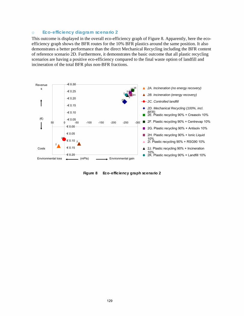
129
o Eco-efficiency diagram scenario 2 This outcome is displayed in the overall eco-efficiency graph of Figure 8. Apparently, here the eco-efficiency graph shows the BFR routes for the 10% BFR plastics around the same position. It also demonstrates a better performance than the direct Mechanical Recycling including the BFR content of reference scenario 2D. Furthermore, it demonstrates the basic outcome that all plastic recycling scenarios are having a positive eco-efficiency compared to the final waste option of landfill and incineration of the total BFR plus non-BFR fractions.
-€ 0.30
-€ 0.25
-€ 0.20
-€ 0.15
-€ 0.10
-€ 0.05
€ 0.00
€ 0.05
€ 0.10
€ 0.15
€ 0.20
-300-250-200-150-100-50050
2A. Incineration (no energy recovery)
2B. Incineration (energy recovery)
2C. Controlled landfill
2D. Mechanical Recycling (100%, incl.BFR)2E. Plastic recycling 90% + Creasolv 10%
2F. Plastic recycling 90% + Centrevap 10%
2G. Plastic recycling 90% + Antisolv 10%
2H. Plastic recycling 90% + Ionic Liquid10%2I. Plastic recycling 90% + RSG90 10%
2J. Plastic recycling 90% + Incineration10%2K. Plastic recycling 90% + Landfill 10%
Revenues
(€)
Costs
Environmental loss (mPts) Environmental gain
2
2C2
2D
2E2F2G
2H2I
2
2
Figure 8 Eco-efficiency graph scenario 2
130
• Discussion o Reflection on the assumptions The robustness and reliability of the results is related to two general aspects. At first, the various assumptions and data quality and availability is discussed here by qualitative means. Secondly, the choice for the environmental impact assessment methodology and the single environmental indicators as discussed in the next section. The influence of the most important assumptions is discussed in a qualitative way: 1. Plastics sorting and separation efficiency: The current settings for sorting of plastics is assumed
to have a 100% efficiency. The potential negative of other plastics present in the BFR fraction is left out of scope and might decrease the recovery percentages. This also includes possible metal and other materials present ending-up in the inerts/BFR residue to landfill. On the other hand, the solvent routes make a separation of such additives or contaminations possible.
2. Market prices for both BFR and non-BFR mixed styrene based plastics are obtained from Axion recycling and presented in Table 5. When applicable, deviating prices per kg will change the eco-efficiency graphs with a similar amount per kg.
3. Gate fees are assumed for the BFR routes of scenario 1 in relation to final waste disposal routes. Included is also the economic effect of replacing the caloric value of Municipal Solid Waste by material with a much higher caloric value which has its effect of the limited ‘thermal capacity’ of incinerators at the moment. However, in the future it might be possible that the current caloric value of MSW in the UK will decrease due to more separation of certain streams (other plastics). As a consequence, the calculated gate fee could decrease at the incinerator in the future.
4. The calculations for both incineration and RGS90, assumingly, no additional dioxins are emitted compared to current emissions from MSW. For incineration with a wet flue gas cleaning this effect is realistic as no higher influence of the Bromine content on the dioxin levels is found. However, in practice this needs to be checked for UK incinerators with a dry cleaning system. The expected effect of a higher activated carbon consumption in order to prevent this is not included in the calculations.
5. No VOC emissions are taken into account for solvent recovery steps and extruding of the produced polymer with remaining solvent present. This might have a slight effect on the emissions.
6. The modelling of the thermodynamics of the RGS90 process and more specific of the internal oil consumption for the energy supply, is rather uncertain. Currently, 10% of the produced oil is assumed to be used in the pyrolyser internally. A higher or lower amount would influence the environmental gains of the process.
The last remark on the assumptions and data reliability is the perhaps the most important one: The solvent routes in particular are based on process modelling and lab-scale testing. The estimates on the actual mass and energy balances are expected to be realistic values. However, the quality of this screening eco-efficiency analysis can be improved by checking the outcomes of the future processes with real-life data from full scale operations.
131
o Environmental ranking for grouped impact categories Another important discussion aspect is the choice for using single environmental indicators. The stability of the results is checked for scenario 1 by calculating the three grouped environmental themes of Human Health, Ecosystem Quality and Resource Depletion as well as all individual impact categories. See also the Table in this Appendix for all abbreviations used. In Table 9, the environmental ranking under the three grouped themes as well as the often used category of global warming (in CO2 equivalents), is summarised. The table provides important guidance on the often debated stability of environmental outcomes under single indicator calculations. Here the ranking of the best performing options (1E. Creasolv and 1F. Centrevap) remains above the other options, followed by 1H. Ionic Liquid and 1G. Antisolv, followed by the thermal options 1B. Incineration and 1I. RSG90 and finally by 1C. Controlled Landfill. The same conclusion can be drawn from the individual impact categories, with one surprising exception: For Human Health – Toxicity the thermal options 1I. RGS90 and 1B. Incineration are preferable above the other options. The reason is the toxicity effect related to the avoided energy production compared to the other options where the replacement of primary materials is adding less to the environmental gain.
Table 9. Environmental ranking of scenario 1 for grouped environmental themes EI99 overall HH EQ RD CO2 1E. Creasolv 1 2 1 2 1 1D. Mechanical Recycling (100%, incl. BFR) 2 1 3 1 2 1F. Centrevap 3 3 2 3 3 1H. Ionic Liquid 4 6 4 4 4 1G. Antisolv 5 5 5 5 7 1I. RGS90 6 7 6 6 5 1B. Incineration (energy recovery) 7 4 8 8 6 1C. Controlled landfill 8 8 7 7 8
132
Appendix 5D – Detailed results for QWERTY analysis
Abbreviation and short explanation environmental impact categories Abbreviation Impact Category/ Group Name Comment EI99 default Eco-Indicator'99, default weighting set HH Human Health, grouped EQ Ecosystem Quality, grouped RD Resource Depletion, grouped HH carc Human Health, carcinogenic effects HH resporg Human Health, respiratory organics HH respinorg Human Health, respiratory inorganics HH clim Human Health, climate change (in CO2 equiv.) HH rad Human Health, radiation Not applicable/ relevant HH ozone Human Health, ozone layer depletion HH tox Human Health, toxicity EQ ecotox Ecosystem Quality, ecotoxicity EQ acid Ecosystem Quality, acidification,
eutrophication
EQ land Ecosystem Quality, land-use Not applicable/ relevant RD min Resource Depletion, minerals RD fossil Resource Depletion, fossil fuels
In the next graphs environmental burden is directed above, environmental gain below. HH grouped EQ grouped
RD grouped HH clim (in kg CO2 equivalent)
(140,00)
(120,00)
(100,00)
(80,00)
(60,00)
(40,00)
(20,00)
-
20,00
40,00
60,00
Creasolv Plastreccopy Ionic Liquid CentrEvap Antisolv RSG90 Incineration Landfill
TransportGainEmissionsSolventsEnergy
(250,00)
(200,00)
(150,00)
(100,00)
(50,00)
-
50,00
100,00
Creasolv Plastreccopy Ionic Liquid CentrEvap Antisolv RSG90 Incineration Landfill
TransportGainEmissionsSolventsEnergy
(15,00)
(10,00)
(5,00)
-
5,00
10,00
Creasolv Plastreccopy Ionic Liquid CentrEvap Antisolv RSG90 Incineration Landfill
TransportGainEmissionsSolventsEnergy
(4,00)
(3,00)
(2,00)
(1,00)
-
1,00
2,00
3,00
4,00
Creasolv Plastreccopy Ionic Liquid CentrEvap Antisolv RSG90 Incineration Landfill
TransportGainEmissionsSolventsEnergy
133
HH carc HH resporg HH respinorg HH clim
HH ozone HH tox
(7,00)
(6,00)
(5,00)
(4,00)
(3,00)
(2,00)
(1,00)
-
1,00
2,00
3,00
Creasolv Plastreccopy Ionic Liquid CentrEvap Antisolv RSG90 Incineration Landfill
TransportGainEmissionsSolventsEnergy
(0,40)
(0,35)
(0,30)
(0,25)
(0,20)
(0,15)
(0,10)
(0,05)
-
0,05
0,10
Creasolv Plastreccopy Ionic Liquid CentrEvap Antisolv RSG90 Incineration Landfill
TransportGainEmissionsSolventsEnergy
(60,00)
(40,00)
(20,00)
-
20,00
40,00
60,00
Creasolv Plastreccopy Ionic Liquid CentrEvap Antisolv RSG90 Incineration Landfill
TransportGainEmissionsSolventsEnergy
(15,00)
(10,00)
(5,00)
-
5,00
10,00
15,00
Creasolv Plastrec Ionic Liquid CentrEvap Antisolv RSG90 Incineration Landfill
TransportGainEmissionsSolventsEnergy
(10,00)
(5,00)
-
5,00
10,00
15,00
20,00
Creasolv Plastreccopy Ionic Liquid CentrEvap Antisolv RSG90 Incineration Landfill
TransportGainEmissionsSolventsEnergy
(0,080)
(0,070)
(0,060)
(0,050)
(0,040)
(0,030)
(0,020)
(0,010)
-
0,010
Creasolv Plastreccopy Ionic Liquid CentrEvap Antisolv RSG90 Incineration Landfill
TransportGainEmissionsSolventsEnergy
134
EQ ecotox EQ acid
RD min RD fossil
(6,00)
(4,00)
(2,00)
-
2,00
4,00
6,00
8,00
Creasolv Plastreccopy Ionic Liquid CentrEvap Antisolv RSG90 Incineration Landfill
TransportGainEmissionsSolventsEnergy
(10,00)
(8,00)
(6,00)
(4,00)
(2,00)
-
2,00
4,00
6,00
8,00
Creasolv Plastreccopy Ionic Liquid CentrEvap Antisolv RSG90 Incineration Landfill
TransportGainEmissionsSolventsEnergy
(0,01)
(0,01)
(0,01)
(0,00)
(0,00)
-
0,00
0,00
Creasolv Plastreccopy Ionic Liquid CentrEvap Antisolv RSG90 Incineration Landfill
TransportGainEmissionsSolventsEnergy
(250,00)
(200,00)
(150,00)
(100,00)
(50,00)
-
50,00
100,00
Creasolv Plastreccopy Ionic Liquid CentrEvap Antisolv RSG90 Incineration Landfill
TransportGainEmissionsSolventsEnergy

Appendix 5E - Update of White Young Green environmental impact assessment for Phase 3 results
1
Reference: Life Cycle Assessment Addendum Report to WYGE project ref. E4833 – July 2006
Issue Prepared by Checked by Verified by 1 July 2006
R S HALL Consultant Associate ctor
File Ref: N:\Projects\E9001-E9500\E009397\reports\2006 update
White Young Green Environmental Limited, Arndale Court, Headingley, Leeds. LS6 2UJ. Telephone: 0113 278 7111 Facsimile: 0113 275 0623 E-Mail: [email protected]
LIFE CYCLE ASSESSMENT STUDY:
ADDENDUM REPORT
Selected Treatment Processes for WEEE Plastics Containing Brominated Flame Retardants
WHITE YOUNG GREEN ENVIRONMENTAL
LCA of Process Options for BFR’s in WEEE Plastics July 2006 Project No. E9397 Addendum
TABLE OF CONTENTS
Page No. 2.0 Background 1 2.0 Aims 1 3.0 Introduction 2 3.1 Summary of Phase 2 Life Cycle Assessment Analysis 2
3.2 Summary of Phase 3 Process Trials 4 4.0 Goals and Scope of the Study 5
4.1 Goals of the Study 5 4.2 Scope of the Study 5
4.2.1 The Functional Unit 6 4.2.2 System Boundaries 6
4.2.3 Data quality 7
5.0 Methodology 8 6.0 Impact Assessment 9
6.1 Impact Assessment: Creasolv 9 6.1.1 Results from Quantitative Assessment 9 Environmental Indicators 6.1.2 Results from Quantitative Assessment - 11 Overall Environmental Indicators 6.2 Impact Assessment: Centrevap 12 6.2.1 Results from Quantitative Assessment 12 Environmental Indicators 6.2.2 Results from Quantitative Assessment - 14 Overall Environmental Indicators
7.0 Conclusions 15 8.0 Limitations 15 11.0 References 16 12.0 Glossary 18
APPENDICES Appendix A Report Conditions Appendix B Energy Conversion Factors Appendix C Assumptions
LCA of Process Options for BFR’s in WEEE Plastics 1 July 2006 Project No. E9397 Addendum
Life-cycle Assessment of Waste Treatment Options for Waste Electrical and
Electronic Plastic containing Brominated Flame Retardant Compounds 4.0 Background In 2005, White Young Green Environmental (WYGE) were commissioned by Axion Recycling to undertake a Life Cycle Assessment (LCA) study of designated processing options for plastics containing brominated flame retardants as part of the Waste and Resources Action Programme (WRAP) funded project ‘Develop a process to separate brominated flame retardants from WEEE polymers.’ This study was based on mass balance data available from preliminary practical trials and process design work undertaken in Phase 2 of the project and generic, publicly available data. Following the principals detailed in ISO 14040, the potential environmental impacts of four new process options identified in Phase 1 of the study were compared to the traditional waste disposal and recovery options of incineration, feedstock recycling and landfill. The results of this study were included within Interim Report 2 for the project, published by WRAP in August 2005 (WYGE project ref. no. E4833). 5.0 Aims Following the completion of Phase 3 of this study, WYGE have been commissioned by Axion Recycling to update the quantitative Life Cycle Assessment (LCA) study for those two processes for which practical trials were undertaken in Phase 3, the Creasolv and Centrevap processes, using updated mass balance data collected during the practical trials undertaken in Phase 3. The potential environmental impacts from these processes were compared to those traditional waste disposal and recovery processes of landfill and incineration using those environmental indicators adopted in the original study. This report forms an addendum to the original WYGE project report no. E4833, as detailed in the Interim 2 Report: ‘Develop a process to separate brominated flame retardants from WEEE polymers’ and summarises the additional work which has been undertaken, based on the original study. Background information, detailed methodology, including the results of the qualitative and quantitative assessments and discussions from the original LCA study are not included within this report. As such this addendum report should be read in conjunction with the original study report (WYGE Ref. E4833) included within the Interim 2 Report for the project published in August 2005 by WRAP.
LCA of Process Options for BFR’s in WEEE Plastics 2 July 2006 Project No. E9397 Addendum
6.0 Introduction
Brominated flame retardants (BFR’s) are compounds containing bromine which are added to materials such as plastics to inhibit or suppress the ability of materials to burn and are widely found in electronic and electrical equipment, furniture, paints and textiles.
Despite the importance these compounds have on enhancing the safety of items such as electronic and electrical equipment, the production and use of some BFR compounds is now prohibited due to the potentially hazardous nature and toxicological effects of these compounds, (i.e. DeBB, Penta-PDE, Octa-BDE) and there is continuing concerns about the safety of others, i.e. Deca-BDE and its potential to degrade into lower brominated PBDE’s. In addition, the longevity of some electrical and electronic equipment (E&E) units will ensure that plastics containing these compounds and in particular those which are currently banned, will continue to find their way into the waste stream for a number of years.
In an effort to prevent and reduce the disposal of waste electrical and electronic equipment (WEEE) and promote and encourage the recovery and closed-loop recycling of these items, the Waste Electrical and Electronic Equipment (WEEE) Directive (2002/96/EC) was introduced. Under this Directive, the selective treatment of a number of materials and components commonly found within WEEE is required in order to avoid the dispersal of pollutants and encourage the recovery and recycling of WEEE components. Amongst those materials which are required to be treated prior to disposal / recovery are plastics containing brominated flame retardants. The aims of this Directive are further supported by the Restriction of the Use of Certain Hazardous Substances in Electrical and Electronic Equipment (RoHS) (02/95/EC) Directive, which requires that from 1st July 2006, new E & E equipment placed onto the market contains less than 0.1% PBB and PBDE’s.
In the face of these legislative drivers, the Waste and Resource Action Programme (WRAP) has identified that one of the barriers to the closed-loop recycling of plastic polymers from WEEE in the UK is the need to remove unwanted additives from the plastic polymers before they can be reused, and these include BFR’s. To address this technical barrier, WRAP have funded a study to investigate potential commercially viable techniques for extracting BFR’s from WEEE polymers in order to create better opportunities for the closed–loop recycling of WEEE polymers back into new electronic and electrical equipment.
Axion Recycling Ltd. has been appointed to lead a project to develop a process to separate brominated flame retardants from WEEE polymers. This study has been phased to enable the issues concerning separating BFRs from WEEE polymers to be qualified, current technologies to be reviewed, practical trials and process design works to be undertaken and assessments made to determine which of these technologies have the potential to be commercially viable in the UK.
6.1 Summary of Phase 2 Life Cycle Assessment Analysis
The potential environmental impacts of the four selected potential new process options Creasolv, Centrevap Ionic Liquids and Antisolvent processes, were assessed using the four environmental indicators chosen and as detailed in the Phase 2 report for the project and compared to those anticipated from traditional recovery options, such as incineration with energy recovery, landfill and feedstock recycling.
Of those four new processes investigated for separating BRF from plastic polymers, the results of the quantitative analysis suggested that the best environmentally performing processes were the Creasolv and Centrevap processes, presenting low – medium overall potential environmental impacts (figure 1). The potential environmental impacts resultant from these processes appears to compare favourably with those perceived impacts for landfill and incineration (with and without energy recovery).
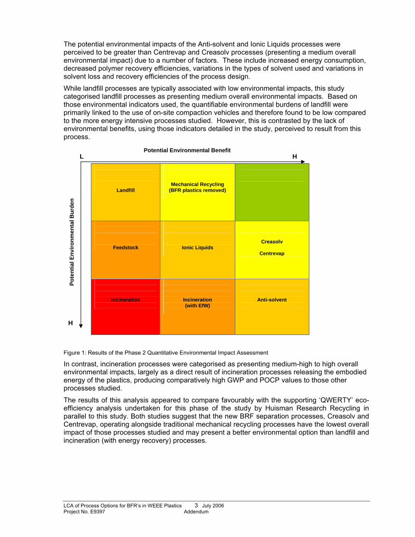
LCA of Process Options for BFR’s in WEEE Plastics 3 July 2006 Project No. E9397 Addendum
The potential environmental impacts of the Anti-solvent and Ionic Liquids processes were perceived to be greater than Centrevap and Creasolv processes (presenting a medium overall environmental impact) due to a number of factors. These include increased energy consumption, decreased polymer recovery efficiencies, variations in the types of solvent used and variations in solvent loss and recovery efficiencies of the process design.
While landfill processes are typically associated with low environmental impacts, this study categorised landfill processes as presenting medium overall environmental impacts. Based on those environmental indicators used, the quantifiable environmental burdens of landfill were primarily linked to the use of on-site compaction vehicles and therefore found to be low compared to the more energy intensive processes studied. However, this is contrasted by the lack of environmental benefits, using those indicators detailed in the study, perceived to result from this process.
Figure 1: Results of the Phase 2 Quantitative Environmental Impact Assessment
In contrast, incineration processes were categorised as presenting medium-high to high overall environmental impacts, largely as a direct result of incineration processes releasing the embodied energy of the plastics, producing comparatively high GWP and POCP values to those other processes studied.
The results of this analysis appeared to compare favourably with the supporting ‘QWERTY’ eco-efficiency analysis undertaken for this phase of the study by Huisman Research Recycling in parallel to this study. Both studies suggest that the new BRF separation processes, Creasolv and Centrevap, operating alongside traditional mechanical recycling processes have the lowest overall impact of those processes studied and may present a better environmental option than landfill and incineration (with energy recovery) processes.
Potential Environmental Benefit L H
H
Pote
ntia
l Env
ironm
enta
l Bur
den
Landfill
Mechanical Recycling (BFR plastics removed)
Feedstock
Ionic Liquids
Creasolv
Centrevap
Incineration
Incineration (with EfW)
Anti-solvent
LCA of Process Options for BFR’s in WEEE Plastics 4 July 2006 Project No. E9397 Addendum
6.2 Summary of Phase 3 Process Trials Phase 3 of the project involved practical technical scale testing of those processes highlighted in Phase 2 which were recommended for further development and evaluation based on laboratory trials and environmental and economic assessments. These processes were identified as being the Creasolv and Centrevap processes.
The results of these practical trials indicate that the Creasolv process has the potential to be commercially viable in the UK context and demonstrates the most potential for separating BRF species from WEEE polymers. Given the results of theses trials, the outcome of the Phase 3 study recommended that the Creasolv process should be developed and assessed further through larger scale trials.
In contrast, the Centrevap process was shown not to be able to achieve significant reductions in the BFR content of the polymer and is therefore not a suitable process for separating BFR species from WEEE polymers. However, the results of the practical trials indicate that the process may be a good, robust alternative treatment process for removing insoluble impurities for a wide range of polymers.
Based on these results, the Centrevap processes can not be considered as a comparable, alternative treatment process to Creasolv, however, it could be a commercially viable solvent process capable of removing other impurities to the sub-micron level from none BFR-containing polymers. As such, further practical trials will be undertaken on the Centrevap process to evaluate this potential alongside the Creasolv process.
LCA of Process Options for BFR’s in WEEE Plastics 5 July 2006 Project No. E9397 Addendum
4.0 Goals and Scope of the Study 4.3 Goals of the Study The objective of the study was to update the original environmental impact assessment work undertaken in Phase 2 using new updated mass balance data provided by Axion Recycling Ltd, resulting from Phase 3 practical trials for the Centrevap and Creasolv processes.
The results of Phase 3 practical trials demonstrate that the Centrevap process can not reduce the BFR content of WEEE polymers to set target levels and therefore can no longer be directly assessed against the Creasolv process, which can. However, the project team indicate that the Centrevap process could be a viable process for removing insoluble impurities from none BFR-containing polymers and is therefore being considered in further trials. Therefore the original environmental impact assessment work for the Centrevap process will be updated to provide an indication as to the potential environmental impacts from this process as a treatment option for non-BFR WEEE plastic polymers.
While it is understood that the process itself will not be affected by replacing a BFR-containing feedstock with a non-BFR-containing polymer throughput, it is unclear as to whether factors such as solvent loss or energy consumption will be impacted. As such, this assessment should be considered as an indicative assessment only as to the potential environmental impacts of this process as practical trials using non-BFR containing polymers have yet to be undertaken. .
The environmental impacts for each of the new solvent processes will be compared to the potential environmental impacts resulting from the traditional disposal options of landfill and incineration (with and without energy recovery).
This study is based on the background data and assumptions used in the original study and should be read in conjunction with the original report. This study also follows the principles and methods of the ISO 14040 Standard Environmental Management – Life Cycle Assessment – Principles and Framework (1997a).
4.4 Scope of the Study While the Creasolv process was identified as the only suitable and commercially viable process for separating BRF species from WEEE polymers, it is understood that both processes will undergo further large scale testing in order to asses their potential as a future solvent based recycling process. The results of the assessment for each of the novel processes will therefore not be directly comparable as the throughput material is different.
It is understood that the source of input material has not changed between Phase 2 and Phase 3 practical trials and therefore this study is based on those material input assumptions made in the original study, including;
• Small WEEE items such as mobile phones, MP3 players etc. are excluded;
• WEEE dismantling and pre-sorting of WEEE plastics has taken place to produce a mix of plastic material that is dominated by the styrenic polymers HIBS (High Impact Polystyrene), ABS (Acrylonitrile Butadiene Styrene) and PC (Polycarbonate) in equal proportions;
• That substituted materials resulting from the separation processes are virgin HIPS, PC and ABS polymers.
• That feedstock material comprises 10% BFR, 0.8% Antimony and 10% inert materials.
• The main brominated flame retardants considered to be present in these polymers are: TBBPA (forming 7% in PC/ABS polymers and 5% in ABS polymers), Deca-BDE (forming 10% in HIPS polymers and 3% in ABS polymers), Octa-BDE (forming 5% in ABS polymers) and TBPE (forming 0.5% in ABS polymers).
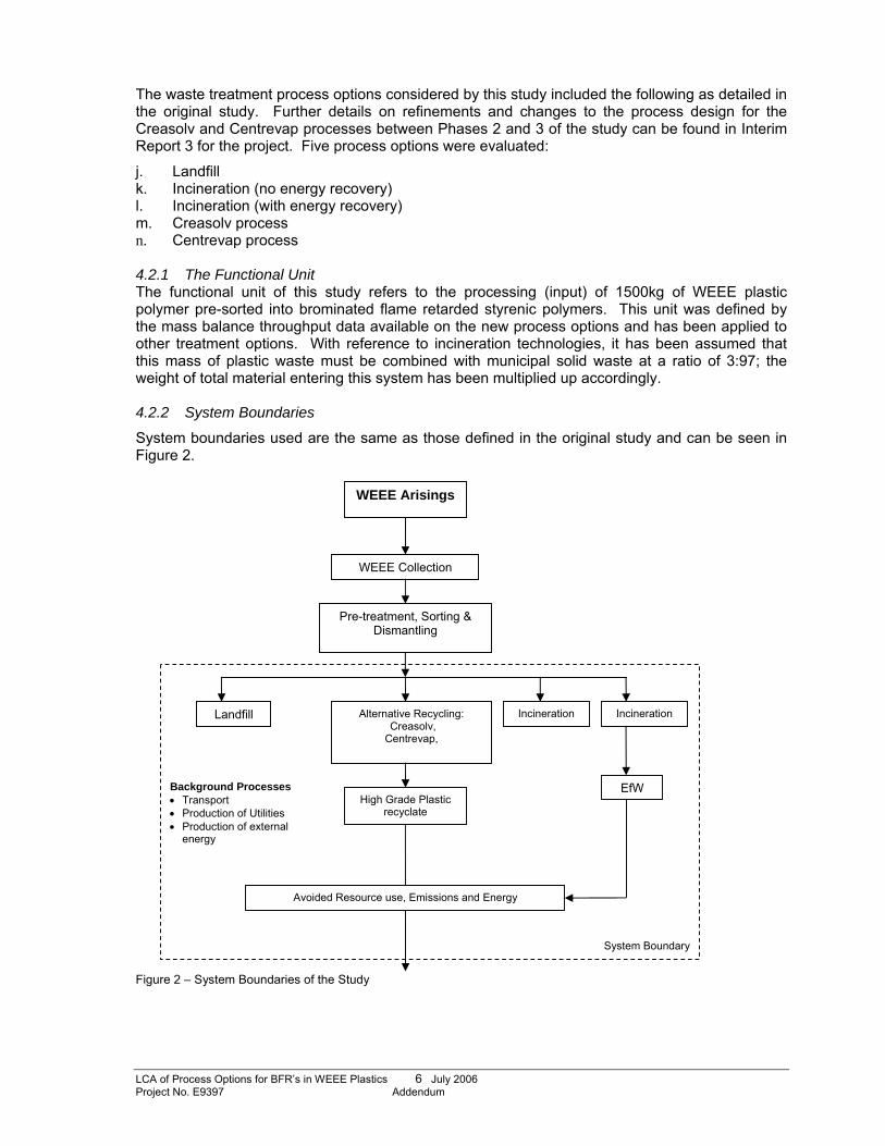
LCA of Process Options for BFR’s in WEEE Plastics 6 July 2006 Project No. E9397 Addendum
The waste treatment process options considered by this study included the following as detailed in the original study. Further details on refinements and changes to the process design for the Creasolv and Centrevap processes between Phases 2 and 3 of the study can be found in Interim Report 3 for the project. Five process options were evaluated:
j. Landfill k. Incineration (no energy recovery) l. Incineration (with energy recovery) m. Creasolv process n. Centrevap process 4.2.1 The Functional Unit The functional unit of this study refers to the processing (input) of 1500kg of WEEE plastic polymer pre-sorted into brominated flame retarded styrenic polymers. This unit was defined by the mass balance throughput data available on the new process options and has been applied to other treatment options. With reference to incineration technologies, it has been assumed that this mass of plastic waste must be combined with municipal solid waste at a ratio of 3:97; the weight of total material entering this system has been multiplied up accordingly. 4.2.2 System Boundaries
System boundaries used are the same as those defined in the original study and can be seen in Figure 2.
Figure 2 – System Boundaries of the Study
WEEE Arisings
Pre-treatment, Sorting & Dismantling
Landfill Incineration
WEEE Collection
EfW High Grade Plastic
recyclate
System Boundary
Background Processes • Transport • Production of Utilities • Production of external
energy
Avoided Resource use, Emissions and Energy
Alternative Recycling: Creasolv, Centrevap,
Incineration
LCA of Process Options for BFR’s in WEEE Plastics 7 July 2006 Project No. E9397 Addendum
As the study was conducted with a view to providing a broad overview of the potential environmental impact and comparable environmental performance of the different waste treatment processes, only those main consumables into each system were considered, i.e. primary energy, plastic polymer, inerts, solvents, water while output emissions inventories were restricted to the main species characterized in energy emission inventories; carbon dioxide, carbon monoxide, nitrogen oxides (NOx), sulphur dioxide, Methane, non-methane Volatile Organic Hydrocarbons (NMVOC’s). Emissions to water have been specifically excluded.
4.2.3 Data quality Data available on the new recycling processes was obtained from practical trials undertaken during Phase 3 of the project and compiled mass balance data produced by Axion Recycling. As with previous data, this information was only available at an aggregated level with only major material flows detailed and no break down of energy consumption sources or measured emissions data available. As such, realistic assumptions have been made where required and publicly available data used with regards to emissions and energy data as detailed in the original study to fill in data gaps.
Following Phase 3, process specific emissions data for the Creasolv and Centrevap processes, with regards to dioxin, furan and BFR emissions have yet to be collated and therefore detailed inventory data remains unavailable.
LCA of Process Options for BFR’s in WEEE Plastics 8 July 2006 Project No. E9397 Addendum
6.0 Methodology The methodology followed for the update of this LCA is based on the methodology detailed in the original report (WYGE project ref. E4833), as found in Interim Report 2 for this project. The environmental impact categories used as the same as those detailed in the original study. These are; • Global Warming • Abiotic Resource Use • Environmental toxicity • Photo-oxidant formation Please refer to the original study for information regarding the choice and background of environmental indicators. Quantitative data was obtained for three of the four environmental impact categorises chosen for this study; primary energy consumption, Global warming potential (GWP) and Photochemical Ozone Creation Potential (POCP). Quantitative data remains unavailable for dioxin / furan and BRF emissions resulting from the Creasolv and Centrevap processes; therefore a qualitative assessment has again been used to evaluate the potential environmental toxicity of the Creasolv and the Centrevap process to the potential environmental toxicity of landfill and incineration processes. This assessment has not changed from the original study and therefore has not been detailed in this addendum report. For information on the qualitative assessment on potential environmental toxicity, please refer to the original study.
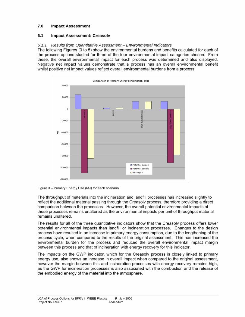
LCA of Process Options for BFR’s in WEEE Plastics 9 July 2006 Project No. E9397 Addendum
7.0 Impact Assessment 6.1 Impact Assessment: Creasolv 6.1.1 Results from Quantitative Assessment – Environmental Indicators The following Figures (3 to 5) show the environmental burdens and benefits calculated for each of the process options studied for three of the four environmental impact categories chosen. From these, the overall environmental impact for each process was determined and also displayed. Negative net impact values demonstrate that a process has an overall environmental benefit whilst positive net impact values reflect overall environmental burdens from a process.
Comparison of Primary Energy consumption (MJ)
-120000
-100000
-80000
-60000
-40000
-20000
0
20000
40000
Creasolv
Landfill
Incineration (no EfW)
Incineration (with EfW
)
MJ
Potential Burden
Potential Benefit
Net Impact
Figure 3 – Primary Energy Use (MJ) for each scenario The throughput of materials into the incineration and landfill processes has increased slightly to reflect the additional material passing through the Creasolv process, therefore providing a direct comparison between the processes. However, the overall potential environmental impacts of these processes remains unaltered as the environmental impacts per unit of throughput material remains unaltered.
The results for all of the three quantitative indicators show that the Creasolv process offers lower potential environmental impacts than landfill or incineration processes. Changes to the design process have resulted in an increase in primary energy consumption, due to the lengthening of the process cycle, when compared to the results of the original assessment. This has increased the environmental burden for the process and reduced the overall environmental impact margin between this process and that of incineration with energy recovery for this indicator.
The impacts on the GWP indicator, which for the Creasolv process is closely linked to primary energy use, also shows an increase in overall impact when compared to the original assessment, however the margin between this and incineration processes with energy recovery remains high, as the GWP for incineration processes is also associated with the combustion and the release of the embodied energy of the material into the atmosphere.
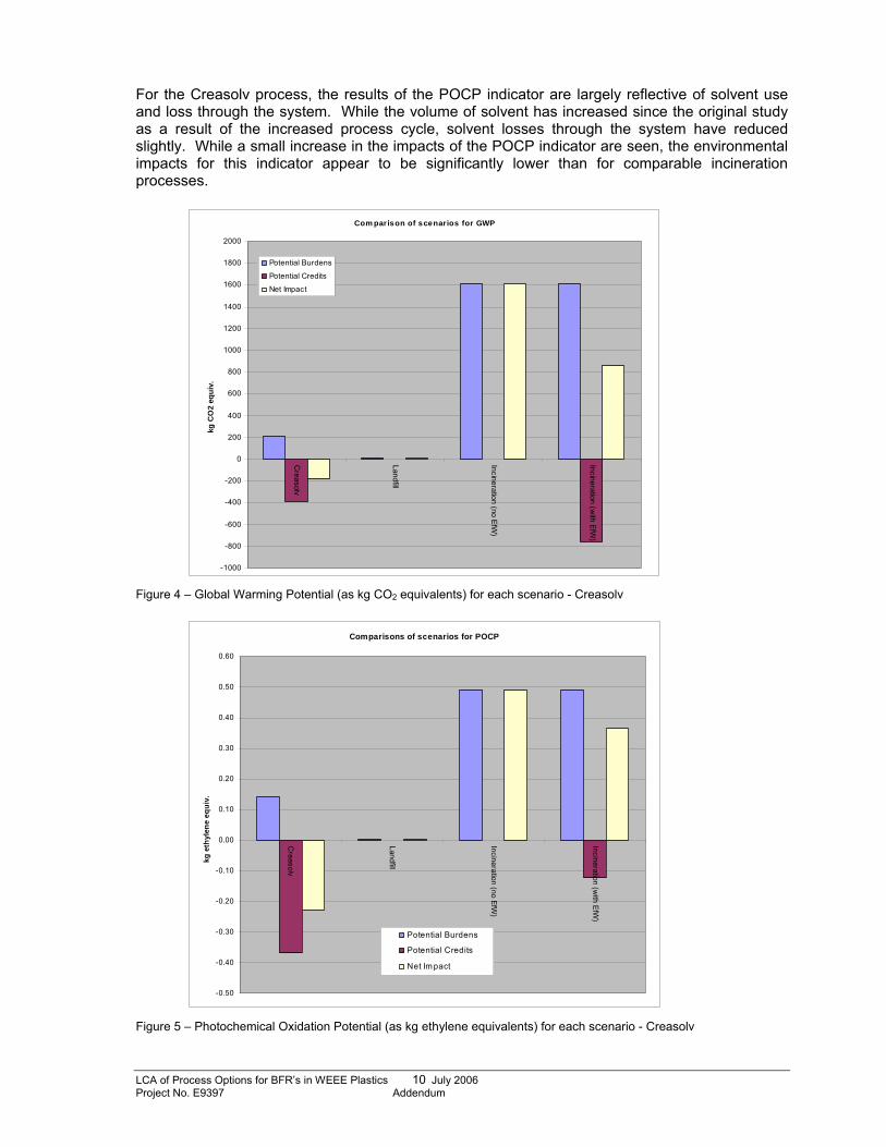
LCA of Process Options for BFR’s in WEEE Plastics 10 July 2006 Project No. E9397 Addendum
For the Creasolv process, the results of the POCP indicator are largely reflective of solvent use and loss through the system. While the volume of solvent has increased since the original study as a result of the increased process cycle, solvent losses through the system have reduced slightly. While a small increase in the impacts of the POCP indicator are seen, the environmental impacts for this indicator appear to be significantly lower than for comparable incineration processes.
Com parison of scenarios for GWP
-1000
-800
-600
-400
-200
0
200
400
600
800
1000
1200
1400
1600
1800
2000
Creasolv
Landfill
Incineration (no EfW)
Incineration (with EfW
)
kg C
O2
equi
v.
Potential Burdens
Potential Credits
Net Impact
Figure 4 – Global Warming Potential (as kg CO2 equivalents) for each scenario - Creasolv
Comparisons of scenarios for POCP
-0.50
-0.40
-0.30
-0.20
-0.10
0.00
0.10
0.20
0.30
0.40
0.50
0.60
Creasolv
Landfill
Incineration (no EfW)
Incineration (with EfW
)
kg e
thyl
ene
equi
v.
Potential Burdens
Potential Credits
Net Im pact
Figure 5 – Photochemical Oxidation Potential (as kg ethylene equivalents) for each scenario - Creasolv
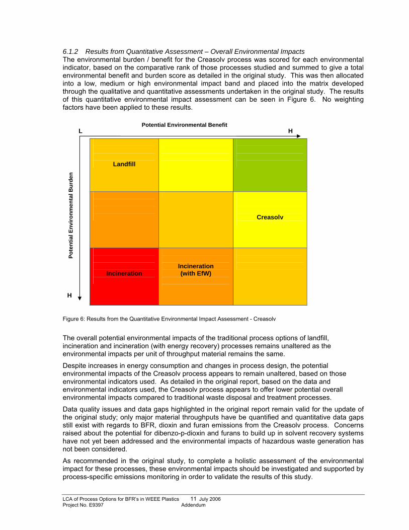
LCA of Process Options for BFR’s in WEEE Plastics 11 July 2006 Project No. E9397 Addendum
6.1.2 Results from Quantitative Assessment – Overall Environmental Impacts The environmental burden / benefit for the Creasolv process was scored for each environmental indicator, based on the comparative rank of those processes studied and summed to give a total environmental benefit and burden score as detailed in the original study. This was then allocated into a low, medium or high environmental impact band and placed into the matrix developed through the qualitative and quantitative assessments undertaken in the original study. The results of this quantitative environmental impact assessment can be seen in Figure 6. No weighting factors have been applied to these results.
Figure 6: Results from the Quantitative Environmental Impact Assessment - Creasolv
The overall potential environmental impacts of the traditional process options of landfill, incineration and incineration (with energy recovery) processes remains unaltered as the environmental impacts per unit of throughput material remains the same.
Despite increases in energy consumption and changes in process design, the potential environmental impacts of the Creasolv process appears to remain unaltered, based on those environmental indicators used. As detailed in the original report, based on the data and environmental indicators used, the Creasolv process appears to offer lower potential overall environmental impacts compared to traditional waste disposal and treatment processes.
Data quality issues and data gaps highlighted in the original report remain valid for the update of the original study; only major material throughputs have be quantified and quantitative data gaps still exist with regards to BFR, dioxin and furan emissions from the Creasolv process. Concerns raised about the potential for dibenzo-p-dioxin and furans to build up in solvent recovery systems have not yet been addressed and the environmental impacts of hazardous waste generation has not been considered.
As recommended in the original study, to complete a holistic assessment of the environmental impact for these processes, these environmental impacts should be investigated and supported by process-specific emissions monitoring in order to validate the results of this study.
Potential Environmental Benefit L H
H
Pote
ntia
l Env
ironm
enta
l Bur
den
Landfill
Creasolv
Incineration
Incineration (with EfW)
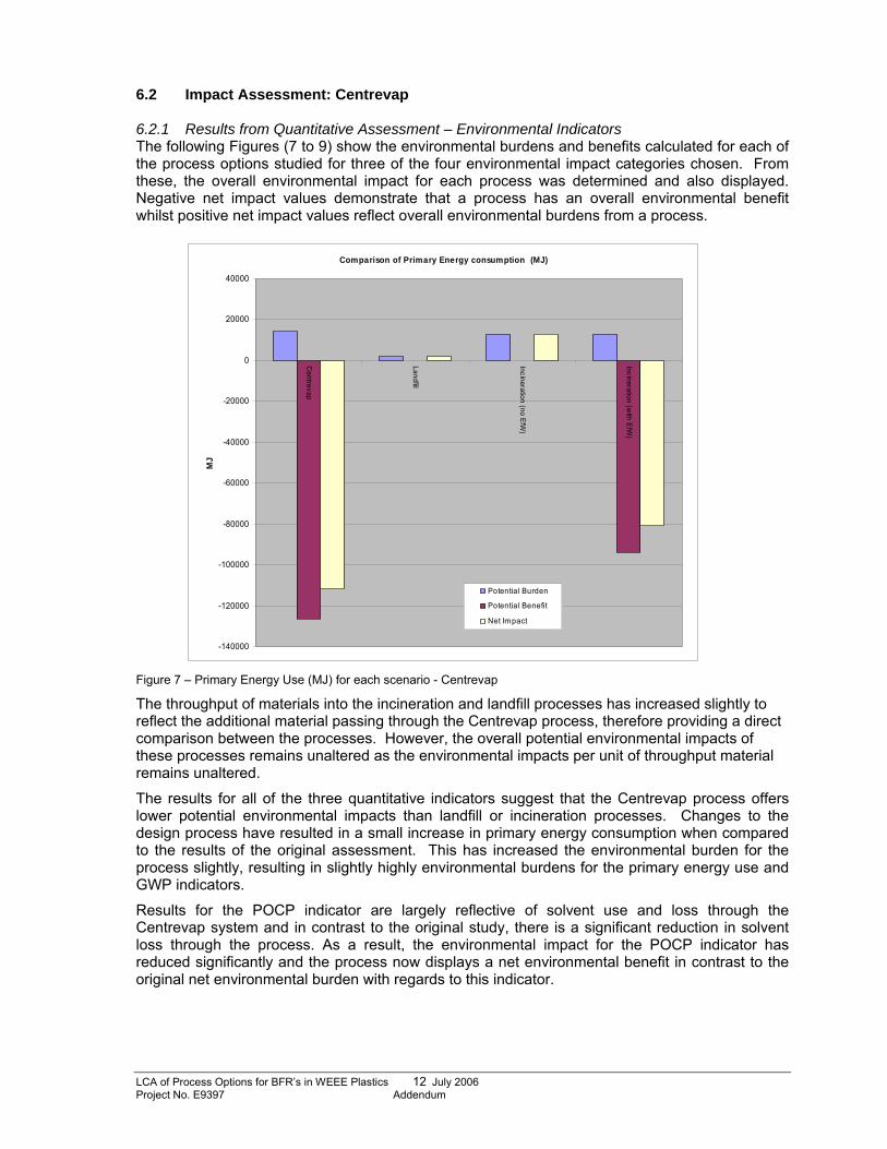
LCA of Process Options for BFR’s in WEEE Plastics 12 July 2006 Project No. E9397 Addendum
6.2 Impact Assessment: Centrevap 6.2.1 Results from Quantitative Assessment – Environmental Indicators The following Figures (7 to 9) show the environmental burdens and benefits calculated for each of the process options studied for three of the four environmental impact categories chosen. From these, the overall environmental impact for each process was determined and also displayed. Negative net impact values demonstrate that a process has an overall environmental benefit whilst positive net impact values reflect overall environmental burdens from a process.
Comparison of Primary Energy consumption (MJ)
-140000
-120000
-100000
-80000
-60000
-40000
-20000
0
20000
40000
Centrevap
Landfill
Incineration (no EfW)
Incineration (with EfW
)
MJ
Potential Burden
Potential Benefit
Net Im pact
Figure 7 – Primary Energy Use (MJ) for each scenario - Centrevap
The throughput of materials into the incineration and landfill processes has increased slightly to reflect the additional material passing through the Centrevap process, therefore providing a direct comparison between the processes. However, the overall potential environmental impacts of these processes remains unaltered as the environmental impacts per unit of throughput material remains unaltered.
The results for all of the three quantitative indicators suggest that the Centrevap process offers lower potential environmental impacts than landfill or incineration processes. Changes to the design process have resulted in a small increase in primary energy consumption when compared to the results of the original assessment. This has increased the environmental burden for the process slightly, resulting in slightly highly environmental burdens for the primary energy use and GWP indicators.
Results for the POCP indicator are largely reflective of solvent use and loss through the Centrevap system and in contrast to the original study, there is a significant reduction in solvent loss through the process. As a result, the environmental impact for the POCP indicator has reduced significantly and the process now displays a net environmental benefit in contrast to the original net environmental burden with regards to this indicator.
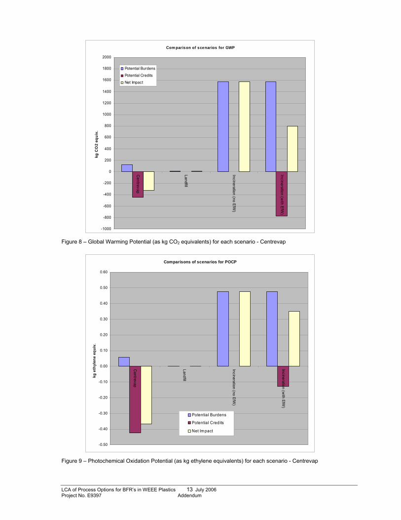
LCA of Process Options for BFR’s in WEEE Plastics 13 July 2006 Project No. E9397 Addendum
Com parison of scenarios for GWP
-1000
-800
-600
-400
-200
0
200
400
600
800
1000
1200
1400
1600
1800
2000
Centrevap
Landfill
Incineration (no EfW)
Incineration (with EfW
)
kg C
O2
equi
v.
Potential Burdens
Potential Credits
Net Impact
Figure 8 – Global Warming Potential (as kg CO2 equivalents) for each scenario - Centrevap
Comparisons of scenarios for POCP
-0.50
-0.40
-0.30
-0.20
-0.10
0.00
0.10
0.20
0.30
0.40
0.50
0.60C
entrevap
Landfill
Incineration (no EfW)
Incineration (with EfW
)
kg e
thyl
ene
equi
v.
Potential Burdens
Potential Credits
Net Im pact
Figure 9 – Photochemical Oxidation Potential (as kg ethylene equivalents) for each scenario - Centrevap
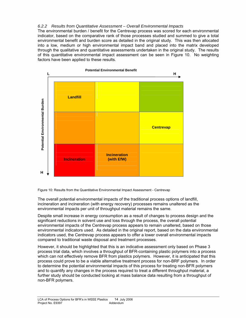
LCA of Process Options for BFR’s in WEEE Plastics 14 July 2006 Project No. E9397 Addendum
6.2.2 Results from Quantitative Assessment – Overall Environmental Impacts The environmental burden / benefit for the Centrevap process was scored for each environmental indicator, based on the comparative rank of those processes studied and summed to give a total environmental benefit and burden score as detailed in the original study. This was then allocated into a low, medium or high environmental impact band and placed into the matrix developed through the qualitative and quantitative assessments undertaken in the original study. The results of this quantitative environmental impact assessment can be seen in Figure 10. No weighting factors have been applied to these results.
Figure 10: Results from the Quantitative Environmental Impact Assessment - Centrevap The overall potential environmental impacts of the traditional process options of landfill, incineration and incineration (with energy recovery) processes remains unaltered as the environmental impacts per unit of throughput material remains the same.
Despite small increase in energy consumption as a result of changes to process design and the significant reductions in solvent use and loss through the process, the overall potential environmental impacts of the Centrevap process appears to remain unaltered, based on those environmental indicators used. As detailed in the original report, based on the data environmental indicators used, the Centrevap process appears to offer a lower overall environmental impacts compared to traditional waste disposal and treatment processes.
However, it should be highlighted that this is an indicative assessment only based on Phase 3 process trial data, which involves a throughput of BFR-containing plastic polymers into a process which can not effectively remove BFR from plastics polymers. However, it is anticipated that this process could prove to be a viable alternative treatment process for non-BRF polymers. In order to determine the potential environmental impacts of this process for treating non-BFR polymers and to quantify any changes in the process required to treat a different throughput material, a further study should be conducted looking at mass balance data resulting from a throughput of non-BFR polymers.
Potential Environmental Benefit L H
H
Pote
ntia
l Env
ironm
enta
l Bur
den
Landfill
Centrevap
Incineration
Incineration (with EfW)
LCA of Process Options for BFR’s in WEEE Plastics 15 July 2006 Project No. E9397 Addendum
8.0 Conclusions Despite the increase in energy consumption required by the Creasolv process as a result of changes in process design, the study appears to demonstrate that the overall environmental impacts of the process have not changed significantly from the results of the original study. As a result, the Creasolv process continues to demonstrates a medium-low overall environmental impact and still appears to be a more favourable process option for the treatment of BFR-containing plastic wastes compared to traditional incineration and landfill processes in terms of those environmental indicators used.
With regards to the Centrevap process, small increases in energy consumption as a result of changes to the design process have not significantly influenced the potential environmental impacts of this process. Changes in the solvent recovery process has significantly improved the performance of the process with regards to the POCP indicator, however, again this does not appear to have a significant impact on the overall performance of the process.
However, due to the different potentials of the Centrevap and the Creasolv processes to extract BFR’s from WEEE polymers the potential environmental impacts of these two processes can not be directly compared as they could potentially be utilised to process difference materials.
Like the Creasolv process, the Centrevap process appears to be a potentially more favourable process option to both landfill and incineration process for non-BFR containing polymers. However, this assessment can be no more than an indicative as all mass balance data relates to process trials undertaken using BFR-containing polymers yet conclusions from the Phase 3 process trials state that this process will only be viable for non-BRF containing plastic polymer wastes. As such, a further assessment of the process should be undertaken using process data which utilises a non-BFR-containing throughput material. This will enable any changes in energy requirements, solvent recovery and polymer recovery efficiency to be fully characterised and related to potential environmental impacts.
8.0 Limitations Data quality issues and data gaps highlighted in the original report remain valid for the update of the original study; only major material throughputs have be quantified and quantitative data gaps still exist with regards to BFR, dioxin and furan emissions from the Creasolv and Centrevap processes. Concerns raised about the potential for dibenzo-p-dioxin and furans to build up in solvent recovery systems have not yet been addressed and the potential environmental impacts of hazardous waste generation has also not been considered. As recommended in the original study, to complete a holistic assessment of the environmental impact for these processes, these environmental impacts should be investigated and supported by process-specific emissions monitoring for the new solvent processes in order to validate the results of this investigation. In addition, a further assessment of the Centrevap process should be undertaken once additional process trials have been completed using a non-BFR-containing plastic polymer throughput material. This is necessary in order to adequately characterise any process changes which may result from the removal of BFR’s from the process design and which may impact on those environmental indicators assessed.
LCA of Process Options for BFR’s in WEEE Plastics 16 July 2006 Project No. E9397 Addendum
9.0 References 33. Action Energy Website: www.actionenergy.org.uk 34. APME (1997a) – Eco-profiles of the European Plastics Industry Report 4: High Impact Polystyrene
(HIPS) 35. APME (1997b) - Ecoprofiles of the European plastics Industry, report 13 , Co-polymers of
Acrylonitrile-Butadiene- Styrene (ABS) and Styrene-Acrylonitrile (SAN), 36. APME (1997c) - Eco-profiles of the European Plastics Industry Report 13: Polycarbonate 37. Axion Recycling Ltd. (2006) – Personal Communication. 38. Boustead, I. (2003) – Eco-profiles of the European Plastics Industry: Methodology. A Report for
APME. 39. BSI EN ISO 14042 (2000) – Environmental Management – Life Cycle Assessment –Life Cycle
Impact Assessment 40. BSI EN ISO 14041 (1998) – Environmental Management – Life Cycle Assessment – Goal and
scope Definition and Inventory Analysis 41. BSI EN ISO 14040 (1997) – Environmental Management – Life Cycle Assessment – Principles and
Framework. 42. Eulálio, C., Capiati, N. J. and S. E. Barbosa – Municipal Plastic Waste – Alternatives for Recycling
with Profit. Taken from the website: www.sperecycling.org 43. European Environment Agency (1997 – Life Cycle Assessment: A guide to approaches,
experiences and information sources. Environmental Issue Series No. 6 44. European Union Risk Assessment Report (2003) – diphenyl ether – octabromo derivative. CAS
No:32536-52-0. EINECS No. 251-087-9. 45. European Union Risk Assessment Report (Draft)(2002) - Bis(pentabromophenyl) ether CAS No:
1163-19-5.EINECS No: 214-604-9. 46. European Union Risk Assessment Report (2001) – diphenyl ether – pentabromo derivative. CAS
No: 32534-81-9. EINECS No. 251-084-2 47. Institute of Chemical Engineers Website: www.icheme.org/sustainability/metrics.pdf 48. Meyer H, Neupert M, Plump W, and Willenberg B (1993). Flame retardants ABS/PC blends in office
machines as examples. Kunststoffe 83, 253-257. 49. McDougall, F.R, White, P.R, Franke, M. and Hindle, (2001) - ‘Integrated Solid Waste Management:
A life-cycle Inventory’. Published by Blackwell Science, Oxford, UK. 50. National Air Emissions Inventory Website: www.aeat.co.uk/netcen/airqual/naei 51. OECD (2004) Brominated Flame Retardants (BFRs): Hazard/Risk Information Sheets. 52. Riess M, Ernst T, Popp R, Schubert T, Thoma H, Vierle O, Ehrenstein GW and van Eldik R (1998).
Analysis of flame retarded polymers and recycling materials. Organohalogen Compounds, 35, 443-446.
53. Söderström G and Marklund S (2001). Combustion of brominated flame retardants. Second International Workshop on Brominated Flame Retardants, May 14-16, Stockholm University, Sweden, pp65-70.
54. Tange L, Vehlow J and Drohmann D (2001). Bromine recovery in incinerators and alternative processes from plastics of E&E equipment containing brominated flame retardants as a sustainable solution. Second International Workshop on Brominated Flame Retardants, May 14-16, Stockholm University, Sweden, pp125-129.
55. Ten Berge W (1995). Risk assessment in relation to European Regulatory Requirements. Conference Proceedings “Legislation and Environment Conference”, European Brominated Flame Retardant Industry Panel, 18 September 1995.
56. Tohka, A. and R. Zevenhoven (2002) – Processing Wastes and Waste-derived fuels Containing Brominated Flame Retardants.
57. van Schijndel. P, van Kasteren, J. TU Eindhoven (2004) - Recycling of WEEE plastic waste at PHB’. A Study for European Brominated Flame Retardant Industry Panel
58. WRAP (2004) – Materials and Products from UK-sources PVC-rich waste. Project no. PLA7-013 59. WRAP (2005) – Develop a Process to Separate Brominated Flame Retardants from WEEE
Polymers (Interim Report 1). Project no. PLA-037.
LCA of Process Options for BFR’s in WEEE Plastics 17 July 2006 Project No. E9397 Addendum
60. WRAP (2005) – Develop a Process to Separate Brominated Flame Retardants from WEEE
Polymers (Interim Report 2). Project no. PLA-037. 61. WRAP (2006) – Develop a Process to Separate Brominated Flame Retardants from WEEE
Polymers (Interim Report 3). Project no. PLA-037.
LCA of Process Options for BFR’s in WEEE Plastics 18 July 2006 Project No. E9397 Addendum
10.0 Glossary ABS Acrylonitrile Butadiene Styrene AP Acidification Potential APME Association of Plastic Manufacturers in Europe BFR Brominated Flame Retardants BDE Diphenyl ethers CFC Chlorofluorocarbons COD Chemical Oxygen Demand DBD Dibenzo-dioxins DBF Dibenzo-furans E & E Electrical and Electronic EfW Energy from Waste EP Eutrophication Potential GWP Global Warming Potential HBCD Hexabromocyclododecane HIP High Impact Polystyrene LCA Life Cycle Assessment MSW Municipal Solid Waste NETCEN National Environment Technology Centre NMVOC Non-methane Volatile Organic Compounds NOx Nitrogen oxides ODP Ozone Depletion Potential PBB Polybrominated biphenyls PBDE Polybrominated Diphenyl ethers PC Polycarbonate POCP Photochemical Oxidation Potential PVC Polyvinyl Chloride TBBPA Tetrabromobisphenol-A TBPE 1,2- (tribromophenoxy) ethane VOC Volatile Organic Compounds WEEE Waste Electrical and Electronic Equipment WRAP Waste and Resources Action Programme
19
APPENDIX A
REPORT CONDITIONS
20
WHITE YOUNG GREEN ENVIRONMENTAL
REPORT CONDITIONS
UPDATE TO THE LIFE CYCLE ASSESSMENT: SUMMARY REPORT OF
SELECTED TREATMENT PROCESSES FOR WEEE PLASTICS CONTAINING BROMINATED FLAME RETARDANTS
This Life Cycle Assessment summary report is produced solely for the benefit of Axion Recycling Ltd. and no liability is accepted for any reliance placed on it by any other party unless specifically agreed in writing otherwise. This report refers, within the limitations stated, to the operational processes as per the information supplied to WYGE. No warranty is given as to the possibility of future changes in the design of these processes. This report is based on reference data provided by Axion Recycling, accessible referenced records and information supplied by those parties referenced in the text. Some of the opinions are based on unconfirmed data and information and are presented as the best that can be obtained without further extensive research. Whilst confident in the findings detailed within this report because there are no exact UK definitions of these matters, being subject to risk analysis, we are unable to give categorical assurances that they will be accepted by authorities or funds etc. without question as such bodies often have unpublished, more stringent objectives. This report is prepared for the proposed uses stated in the report and should not be used in a different context without reference to WYGE. In time improved practices, data quality or amended legislation may necessitate a re-assessment.
21
APPENDIX B
ENERGY CONVERSION FACTORS
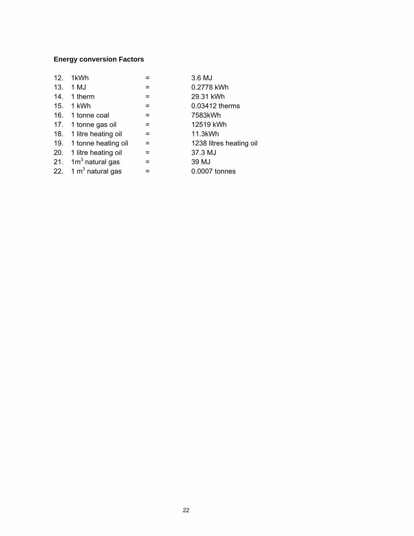
22
Energy conversion Factors 12. 1kWh = 3.6 MJ 13. 1 MJ = 0.2778 kWh 14. 1 therm = 29.31 kWh 15. 1 kWh = 0.03412 therms 16. 1 tonne coal = 7583kWh 17. 1 tonne gas oil = 12519 kWh 18. 1 litre heating oil = 11.3kWh 19. 1 tonne heating oil = 1238 litres heating oil 20. 1 litre heating oil = 37.3 MJ 21. 1m3 natural gas = 39 MJ 22. 1 m3 natural gas = 0.0007 tonnes

23
APPENDIX C
ASSUMPTIONS
24
General 10. All data is based on the input of BFR WEEE polymers into the system. This equates to 1500kg WEEE
plastic. 11. It is assumed that 10% of the throughput material is accounted for by brominated flame retardant
species, 0.8% Antimony and that 10% of the throughput material is accounted for by inert contaminant materials.
12. It is assumed that the polymer composition of the throughput material is primarily Acrylonitrile Butadiene Styrene (ABS), High Impact Polystyrene (HIPS) and Polycarbonate (PC) in equal proportions.
13. It is assumed that 1500kg WEEE plastic will be processed in an hour, for all processes. 14. It is assumed that all energy data provided for the new systems equals the amount of energy required
to process 1500kg of WEEE plastic input, unless where stated. 15. An average draw of electricity of 500kWh has been presumed for the landfill processes. This is in
addition to process specific energies. 16. Environmental burdens have been assessed based on primary energy consumption, fuel usage by on-
site plant and solvent use for each process. 17. Emissions from processes such as plastic extrusion, pellet formation etc. have not been quantified and
therefore not been assessed. 18. Environmental burden is calculated based on the burdens of processing 1500kg of WEEE plastic
waste input into the system. 19. Environmental benefits are calculated based on the requirements of replacing virgin materials with the
weight of the resulting product of the recovery process. 20. It is presumed that the new process will produce high-grade plastic recyclate which will replace virgin
plastic materials. A ratio of 1tonne recyclate to replace 1 tonne virgin plastic has been assumed. Assumptions for Electricity Generation 8. That energy consumption, where not specified is split 60:40 between electricity and oil 9. That primary fuel sources for UK electricity generation are:
a. Coal - 33% b. Gas – 41.5% c. Oil – 1.5% d. Nuclear 24% e. Hydro - 2%
10. No emissions arise from electricity production from nuclear and hydro / renewable energy sources 11. For electricity generation, the combustion efficiencies of the respective fuels are:
a. Coal - 36.2% b. Gas - 46.6% c. Oil - 31%
12. Emission factors are taken from the national air emissions inventory web-site: www.aeat.co.uk/netcen/airqual/naei
13. Emission factors from electricity generation for electricity generation from Power Stations are taken from the national air emission inventory website. Emission factors for coal, natural gas and gas oil have been used.
14. Carbon dioxide emissions are based on a stoichiometric calculation, using the carbon emission factor provided from the National Air Emission Inventory website. (Carbon emission/mol. Wt carbon (12)) x mol. Wt. CO2 (44)).
Environmental Impact Potency Factors 5. Two environmental impact factors have been chosen for this study; Global Warning Potential (GWP)
and Photochemical Oxidation Potential (POCP). 6. These are reported as tonnes of CO2 and tonnes of ethylene equivalents respectively per year. 7. All process data has been calculated based on input into the system over an hour period. The
reported potency factors for these environmental indicators therefore require conversion to kg/hour. 8. Potency factors for GWP and POCP are taken from:
25
www.icheme.org/sustainability/metrics.pdf
GWP CO2 equivalents POCP ethylene equivalents CO2 t/y CO2 kg/hr CO2 t/y
Carbon Dioxide 1 0.114 Carbon Dioxide
1
Carbon Monoxide 3 0.352 Carbon Monoxide
3
NOx 40 4.556 NOx 40 N2O N2O Methane 21 2.397 Methane 21 NMVOC 11 1.256 NMVOC 11 SO2 0 0 SO2 0 Toluene 11 1.256 Toluene 11 Methanol 11 1.256 Methanol 11 Creasolv 1st Solvent
11 1.256 Creasolv 1st Solvent
11
Creasolv 2nd solvent
11 1.256 Creasolv 2nd solvent
11
Ethyl Acetate 11 1.256 Ethyl Acetate 11 Hexyl pyridinium bromide
0 0 Hexyl pyridinium bromide
0
Assumptions for other On-site energy generation 6. That 40% of on-site energy generation for the new processes is generated from heating oil. 7. Combustion efficiency for this process is 81%. This figure is taken from the average UK oil fired steam
boiler combustion efficiencies, which range from 70 - 92% (average = 81%. Source: www.actionenergy.org.uk
8. Emission factors for heating oil are taken from: national air emissions inventory web-site: www.aeat.co.uk/netcen/airqual/naei and those factors for fuel oil for ‘other industry’ have been used.
9. A gross calorific value of 45.6MJ has been used for diesel. 10. Emission factors available for diesel combustion, with the exception of carbon and sulphur dioxide, are
characterised by the travel profile of the vehicle. No travel data was available for compactors. Avoided Emissions: from virgin plastic production 7. Data is taken from the Eco-profiles for polymer plastics produced by APME. Eco-profiles for HIPS,
ABS and PC have been used. 8. It is assumed that the resulting recyclate substitutes these virgin polymers in equal proportions. 9. Data for gross primary fuels and feedstock have been used for energy consumption and feedstock
process. 10. Energy consumption for fuel production and transport processes are specifically excluded. 11. Emissions include fuel use and process operations; emissions from fuel production and transport are
specifically excluded. 12. GWP weighting have been applied to the emission inventories where possible; a weighting of 11 has
been given to all non-methane VOCs groupings, where individual values are not available. 13. POCP weighting have been applied to the emission inventories where possible; averaged values for
the alkanes, alcohols, ketones and alkenes have been used as a representative weighting for the hydrocarbon group and ‘other’ organics; averaged values for aromatic species have been used fro the
26
aromatic and polycyclic hydrocarbon groupings; the aldehyde grouping used average values for individual aldehyde species.
Process specific Assumptions: LANDFILL 5. There is no available data for energy consumption at landfill sites. An average electricity draw of
500kWh has been presumed. 6. There is no data available on transport emissions from compactor vehicles at landfill sites. 7. A fuel consumption figure of 0.6litres diesel per m3 of landfill void filled is quoted in ‘Integrated Solid
Waste Management: A life-cycle Inventory’ (2001) by McDougall, F.R, White, P.R, Franke, M. and Hindle, P and has been used.
8. Emission factors have been taken from national air emissions inventory web-site: www.aeat.co.uk/netcen/airqual/naei relating to industrial off-road transport. These have been used as there is an absence of travel related data for this activity.
Process specific Assumptions: NEW PROCESSES 6. Emission factors from fuel use for plant have been taken from the national air emissions inventory
web-site: www.aeat.co.uk/netcen/airqual/naei relating to industrial off-road transport. 7. Solvent emissions are presumed to amount to 2% of made-up solvent, minus those emissions to
water. 8. A GWP of 11t/y CO2 equivalent has been used for all solvents (equivalent to VOC emissions). 9. A POCP potency factor of 0.596 t/y ethylene equivalent has been used for paraffinic hydrocarbons;
this is an averaged value from alkane, alkene, ketone and alcohol species.
Process specific Assumptions: INCINERATION 12. It is presumed that incineration plants recover power only, not heat; there is no Bromine recovery. 13. Combustion efficiency is calculated at 26%. 14. Assumes that ratio of MSW:BFR WEEE plastics is 97:3. 15. Assumes that BFR can only be incinerated alongside MSW. 16. Calorific value of WEEE plastic is 44.3MJ/kg. This is based on the average calorific values for ABS,
HIPS and PC. 17. Assumes that the calorific value of MSW is 7.06MJ/kg. This figure is taken from ‘Integrated Solid
Waste Management: A life-cycle Inventory’ (2001) by McDougall, F.R, White, P.R, Franke, M. and Hindle, P and is an averaged value for UK MSW.
18. Assumes 0.23m3/ tonne waste of natural gas is required to heat up the incinerator. This figure is taken from ‘Integrated Solid Waste Management: A life-cycle Inventory’ (2001) by McDougall, F.R, White, P.R, Franke, M. and Hindle, P.
19. Emission factors are taken from national air emissions inventory web-site: www.aeat.co.uk/netcen/airqual/naei relating to MSW incineration. Emissions are currently calculated on 100% MSW, not 97%; no information on emissions from plastic combustion is available at the present time.
20. Carbon dioxide emissions are based on a stoichiometric calculation, using the carbon emission factor provided from the National Air Emission Inventory website. (Carbon emission/mol. Wt carbon (12)) x mol. Wt. CO2 (44)).
21. Assumes that power recovered generates electricity; this electricity replaces traditional means of electricity generation.
22. No allowance is made for additional or lower energy requirements of the system by incorporating a higher proportion of plastics into the stream.

Appendix 5F – Huisman update of QWERTY analysis for Phase 3 results
28
Screening Eco-Efficiency Study on Treatment of BFR Plastics
Eco-efficiency and QWERTY analysis on treatment of plastics with brominated flame-retardants in the United Kingdom
Short update report
Date: June 8, 2006 Commissioned by: Roger Morton Axion Recycling Ltd Project manager for the WRAP (The Waste and Resources Action Programme) PLA00037 – Develop a Process to Extract Brominated Flame Retardants from WEEE Polymers Written by: Dr. Ir. Jaco Huisman TU Delft Industrial Design Engineering, Design for Sustainability Program Landbergstraat 15, 2628 CE Delft, The Netherlands [email protected] Huisman Recycling Research
Boschdijk 466, 5622 PD, Eindhoven The Netherlands [email protected]
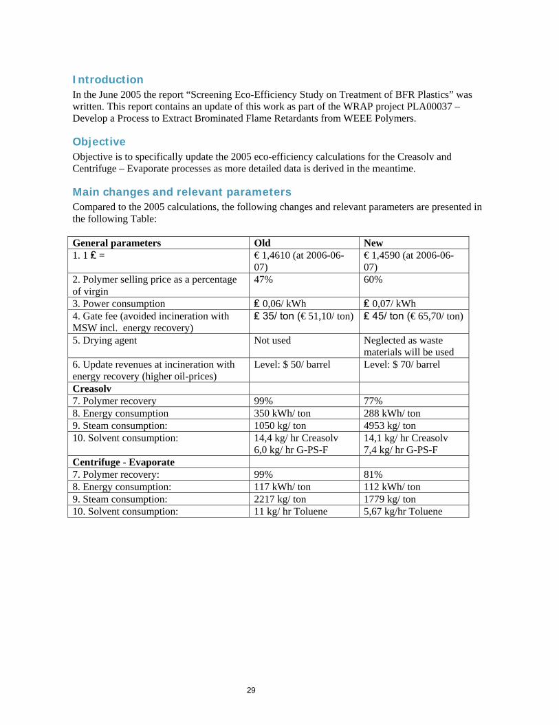
29
Introduction In the June 2005 the report “Screening Eco-Efficiency Study on Treatment of BFR Plastics” was written. This report contains an update of this work as part of the WRAP project PLA00037 – Develop a Process to Extract Brominated Flame Retardants from WEEE Polymers.
Objective Objective is to specifically update the 2005 eco-efficiency calculations for the Creasolv and Centrifuge – Evaporate processes as more detailed data is derived in the meantime.
Main changes and relevant parameters Compared to the 2005 calculations, the following changes and relevant parameters are presented in the following Table: General parameters Old New 1. 1 ₤ = € 1,4610 (at 2006-06-
07) € 1,4590 (at 2006-06-07)
2. Polymer selling price as a percentage of virgin
47% 60%
3. Power consumption ₤ 0,06/ kWh ₤ 0,07/ kWh 4. Gate fee (avoided incineration with MSW incl. energy recovery)
₤ 35/ ton (€ 51,10/ ton) ₤ 45/ ton (€ 65,70/ ton)
5. Drying agent Not used Neglected as waste materials will be used
6. Update revenues at incineration with energy recovery (higher oil-prices)
Level: $ 50/ barrel Level: $ 70/ barrel
Creasolv 7. Polymer recovery 99% 77% 8. Energy consumption 350 kWh/ ton 288 kWh/ ton 9. Steam consumption: 1050 kg/ ton 4953 kg/ ton 10. Solvent consumption: 14,4 kg/ hr Creasolv
6,0 kg/ hr G-PS-F 14,1 kg/ hr Creasolv 7,4 kg/ hr G-PS-F
Centrifuge - Evaporate 7. Polymer recovery: 99% 81% 8. Energy consumption: 117 kWh/ ton 112 kWh/ ton 9. Steam consumption: 2217 kg/ ton 1779 kg/ ton 10. Solvent consumption: 11 kg/ hr Toluene 5,67 kg/hr Toluene
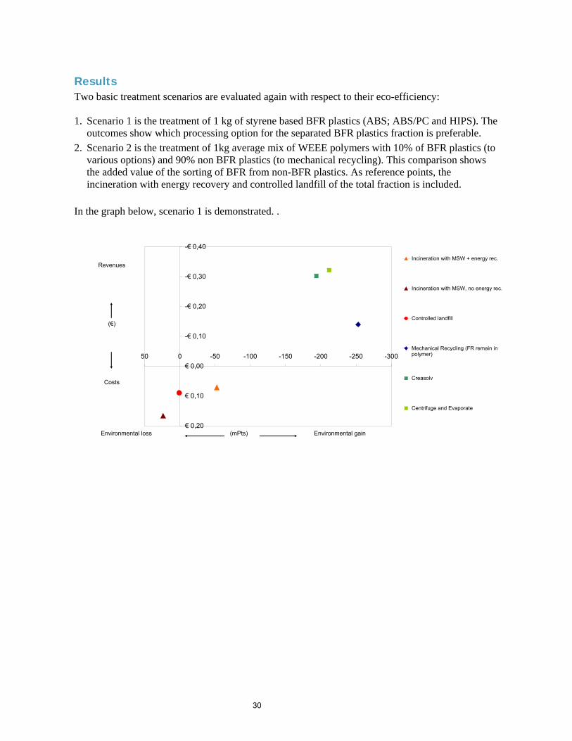
30
Results Two basic treatment scenarios are evaluated again with respect to their eco-efficiency: 1. Scenario 1 is the treatment of 1 kg of styrene based BFR plastics (ABS; ABS/PC and HIPS). The
outcomes show which processing option for the separated BFR plastics fraction is preferable. 2. Scenario 2 is the treatment of 1kg average mix of WEEE polymers with 10% of BFR plastics (to
various options) and 90% non BFR plastics (to mechanical recycling). This comparison shows the added value of the sorting of BFR from non-BFR plastics. As reference points, the incineration with energy recovery and controlled landfill of the total fraction is included.
In the graph below, scenario 1 is demonstrated. .
-€ 0,40
-€ 0,30
-€ 0,20
-€ 0,10
€ 0,00
€ 0,10
€ 0,20
-300-250-200-150-100-50050
Incineration with MSW + energy rec.
Incineration with MSW, no energy rec.
Controlled landfill
Mechanical Recycling (FR remain inpolymer)
Creasolv
Centrifuge and Evaporate
Revenues
(€)
Costs
Environmental loss (mPts) Environmental gain
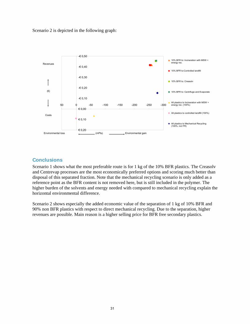
31
Scenario 2 is depicted in the following graph:
Conclusions Scenario 1 shows what the most preferable route is for 1 kg of the 10% BFR plastics. The Creasolv and Centrevap processes are the most economically preferred options and scoring much better than disposal of this separated fraction. Note that the mechanical recycling scenario is only added as a reference point as the BFR content is not removed here, but is still included in the polymer. The higher burden of the solvents and energy needed with compared to mechanical recycling explain the horizontal environmental difference. Scenario 2 shows especially the added economic value of the separation of 1 kg of 10% BFR and 90% non BFR plastics with respect to direct mechanical recycling. Due to the separation, higher revenues are possible. Main reason is a higher selling price for BFR free secondary plastics.
-€ 0,50
-€ 0,40
-€ 0,30
-€ 0,20
-€ 0,10
€ 0,00
€ 0,10
€ 0,20
-300-250-200-150-100-50050
10% BFR to: Incineration with MSW +energy rec.
10% BFR to:Controlled landfill
10% BFR to: Creasolv
10% BFR to: Centrifuge and Evaporate
All plastics to Incineration with MSW +energy rec. (100%)
All plastics to controlled landfill (100%)
All plastics to Mechanical Recycling(100%, incl FR)
Revenues
(€)
Costs
Environmental loss (mPts) Environmental gain
Recommended