CTU 1x3x series CTU 1x4x series Contamination Test Unit
Operating and Maintenance Instructions English (translation of original instructions)
Document No.: 4093420e (Valid from series no.: 0002S01495K000000192) Keep for future reference.
Imprint
CTU 1x3x / 1x4x series en(us) Page 2 / 92
BeWa CTU1xxx 4093420e en-us 2018-05-28.docx 2018-05-24
Imprint
Manufacturer / publisher and responsible for the content: HYDAC FILTER SYSTEMS GMBH Industriestraße 66280 Sulzbach / Saar Germany Telephone: +49 6897 509 01 Fax: +49 6897 509 9046 E-mail: [email protected] Homepage: www.hydac.com Court of Registration: Saarbrücken, HRB 17216 Executive director: Mathias Dieter,
Dipl.Kfm. Wolfgang Haering
Documentation Representative
Mr. Günter Harge c/o HYDAC International GmbH, Industriegebiet, 66280 Sulzbach / Saar Telephone: +49 6897 509 1511 Fax: +49 6897 509 1394 E-mail: [email protected]
© HYDAC FILTER SYSTEMS GMBH
All rights reserved. No part of this work may be reproduced in any form (print, photocopy or by other means) or processed, duplicated or distributed using electronic systems without the written consent of the publisher. These documents have been created and inspected with the greatest care. However, errors cannot be ruled out completely.

Contents
CTU 1x3x / 1x4x series en(us) Page 3 / 92
BeWa CTU1xxx 4093420e en-us 2018-05-28.docx 2018-05-24
Contents
Imprint ............................................................................................................ 2
Documentation Representative ................................................................... 2
Contents ........................................................................................................ 3
Preface ........................................................................................................... 6
Technical Support ........................................................................................ 6 Modifications to the Product ........................................................................ 6 Warranty ...................................................................................................... 6 Using the documentation ............................................................................. 7
Safety Information ........................................................................................ 8
Signal words and their meaning in the safety information and instructions .................................................................................................. 8 Structure of the safety information and instructions ..................................... 9 Warning signs used ..................................................................................... 9 Signs used for giving orders ...................................................................... 10 Used prohibitory signs ............................................................................... 10 Others used symbols ................................................................................. 10 Signs used for the required specialist personnel ....................................... 11
Specialist personnel – Mechanical ......................................................... 11 Specialist personnel – Electricity ............................................................ 11
Observe regulatory information ................................................................. 11 Proper/Designated Use ............................................................................. 12 Improper Use or Use Deviating from Intended Use ................................... 13 Qualifications of personnel / target group .................................................. 14 Wear suitable clothing ............................................................................... 15 Observe regulatory information ................................................................. 15 What to Do in Case of Emergency (EMERGENCY STOP) ....................... 15
Transporting assembly .............................................................................. 16
Storing the assembly .................................................................................. 19
Decoding the model code label ................................................................. 20
Checking the scope of delivery ................................................................. 21
CTU Dimensions ......................................................................................... 22
Outer dimensions ...................................................................................... 22 Analysis chamber dimensions ................................................................... 23
Preparing the CTU for operation ............................................................... 24
Setting up the CTU .................................................................................... 24 Putting the CTU into operation .................................................................. 25
Checking connections and contacts ....................................................... 25
Contents
CTU 1x3x / 1x4x series en(us) Page 4 / 92
BeWa CTU1xxx 4093420e en-us 2018-05-28.docx 2018-05-24
Air extraction within the unit...................................................................... 28
Note when using the test liquid G 60 Spezial ............................................ 28 Connecting an air extractor ........................................................................ 29
Suctioning the machine room of the CTU 1x3x ...................................... 29 Suctioning the machine room and analysis chamber of the CTU 1x4x ........................................................................................................ 30 Setting up the electrical connection of the CTU...................................... 32 Connecting the compressed air .............................................................. 32 Connecting the foot switch ..................................................................... 33
Parts of the CTU .......................................................................................... 34
Operating console .................................................................................. 35
Functional principle .................................................................................... 36
Manual spray extraction............................................................................. 36 Achievable negative control values ........................................................... 37
Operating filter membrane holder / Removing filter membrane ............. 38
Filter membrane holder with union nut ...................................................... 38 Filter membrane holder with clamp ............................................................ 39
Cascading the filter membrane holder .................................................... 40 Filter membrane holder CTMH (ContaminationTest Membrane Holder) ....................................................................................................... 41
Cascading filter membrane holder CTMH .............................................. 42
Opening / Closing door lock ...................................................................... 44
CTU during operation ................................................................................. 45
CTU switching on ...................................................................................... 45 ConTeS Software ...................................................................................... 46 Clean-Room Conditions in the Analysis Chamber - Rinsing of the inner chamber ............................................................................................ 46
Automatic cleansing of the analysis chamber ........................................ 47 Conducting Contamination Testing ............................................................ 48
Spray extraction ..................................................................................... 48 Perform ultrasonic test (optional) ............................................................ 50
Automatic reservoir switchover .................................................................. 52 CTU switching off ...................................................................................... 53
Changing the filter membrane ................................................................... 54
Labeling the removed filter membrane ...................................................... 56
Performing inspection / maintenance ....................................................... 57
User information for the "products under pressure" ................................ 58 Maintenance work overview ...................................................................... 58
Maintenance intervals for CTU 1xx0 with A III cleaner as the test liquid ....................................................................................................... 59
Contents
CTU 1x3x / 1x4x series en(us) Page 5 / 92
BeWa CTU1xxx 4093420e en-us 2018-05-28.docx 2018-05-24
Maintenance intervals for CTU 1xx1 with A III cleaner as the test liquid ....................................................................................................... 59 Maintenance intervals for CTU 1xx1 with water as the test liquid........... 60 Checking / Replacing hoses ................................................................... 60
Changing the filter element ................................................................. 61 Calibrating the flow rate meter................................................................ 63 Calibrating the temperature sensor (ultrasound option only) .................. 64 Cleaning the analysis chamber .............................................................. 65 Clean the diffuser on the filter membrane holder.................................... 65 Cleaning the door ................................................................................... 66
Maintaining statically charged door ..................................................... 66 Change the test liquid ............................................................................. 67
Draining the test liquid ......................................................................... 67 Adding / Filling test liquid .................................................................... 69
Checking the gloves .................................................................................. 72 Permeation of Protective Gloves According to EN 374-3:1994 .............. 73
Installing gloves ......................................................................................... 75 Use electro-statically conductive gloves ................................................. 75
Spare parts list ............................................................................................ 76
Accessories ................................................................................................. 77
Option/variant overview ............................................................................. 78
S2 - Switch vacuum ................................................................................... 78 Variant A – Add flushing ............................................................................ 79 Variant -EA – Extraction Air ....................................................................... 80 Variant F – Flushing .................................................................................. 81 Sensor to signal that the collecting pan is full (optional) ............................ 82
Disposing of the CTU ................................................................................. 83
Technical details ......................................................................................... 84
Attachment .................................................................................................. 85
EC declaration of conformity ...................................................................... 85 Customer Service/ Service ........................................................................ 85 Model Code ............................................................................................... 86 Explanation of terms and abbreviations ..................................................... 87 Index .......................................................................................................... 89
Preface
CTU 1x3x / 1x4x series en(us) Page 6 / 92
BeWa CTU1xxx 4093420e en-us 2018-05-28.docx 2018-05-24
Preface
This operating manual was made to the best of our knowledge. Nevertheless and despite the greatest care, it cannot be excluded that mistakes could have crept in. Therefore please understand that in the absence of any provisions to the contrary hereinafter our warranty and liability – for any legal reasons whatsoever – are excluded in respect of the information in these operating instructions. In particular, we shall not be liable for lost profit or other financial loss. This exclusion of liability does not apply in cases of intent and gross negligence. Moreover, it does not apply to defects which have been deceitfully concealed or whose absence has been guaranteed, nor in cases of culpable harm to life, physical injury and damage to health. If we negligently breach any material contractual obligation, our liability shall be limited to foreseeable damage. Claims due to Product Liability shall remain unaffected.
Technical Support Contact our technical sales department if you have any questions on our product. When contacting us, please always include the model/type designation, serial no. and part-no. of the product: Fax: +49 6897 509 9046 E-mail: [email protected]
Modifications to the Product We would like to point out that changes to the product (e.g. purchasing options, etc.) may result in the information in the operating instructions no longer being completely accurate or sufficient. After modification or repair work that affects the safety of the product has been carried out on components, the product may not be returned to operation until it has been checked and released by a HYDAC technician. Please notify us immediately of any modifications made to the product whether by you or a third party.
Warranty For the warranty provided by us, please refer to the terms of delivery of HYDAC FILTER SYSTEMS GMBH. You will find these under www.hydac.com -> General terms and conditions.
Preface
CTU 1x3x / 1x4x series en(us) Page 7 / 92
BeWa CTU1xxx 4093420e en-us 2018-05-28.docx 2018-05-24
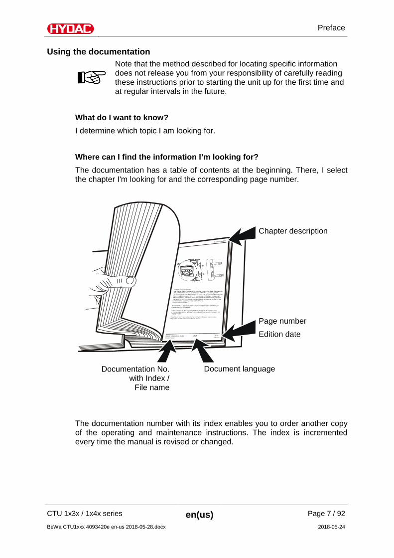
Using the documentation
Note that the method described for locating specific information does not release you from your responsibility of carefully reading these instructions prior to starting the unit up for the first time and at regular intervals in the future.
What do I want to know? I determine which topic I am looking for. Where can I find the information I’m looking for? The documentation has a table of contents at the beginning. There, I select the chapter I'm looking for and the corresponding page number.
deHYDAC Filtertechnik GmbHBeWa 123456a de
Seite x
Produkt / Kapitel
200x-xx-xx
The documentation number with its index enables you to order another copy of the operating and maintenance instructions. The index is incremented every time the manual is revised or changed.
Chapter description
Page number Edition date
Document language Documentation No. with Index /
File name
Safety Information
CTU 1x3x / 1x4x series en(us) Page 8 / 92
BeWa CTU1xxx 4093420e en-us 2018-05-28.docx 2018-05-24
Safety Information
The unit was built according to the statutory provisions valid at the time of delivery and satisfies current safety requirements. Any residual hazards are indicated by safety information and instructions and are described in the operating instructions. Observe all safety and warning instructions attached to the unit. They must always be complete and legible. Do not operate the unit unless all the safety devices are present. Secure the hazardous areas which may arise between the unit and other equipment. Maintain the unit inspection intervals prescribed by law. Document the results in an inspection certificate and keep it until the next inspection.
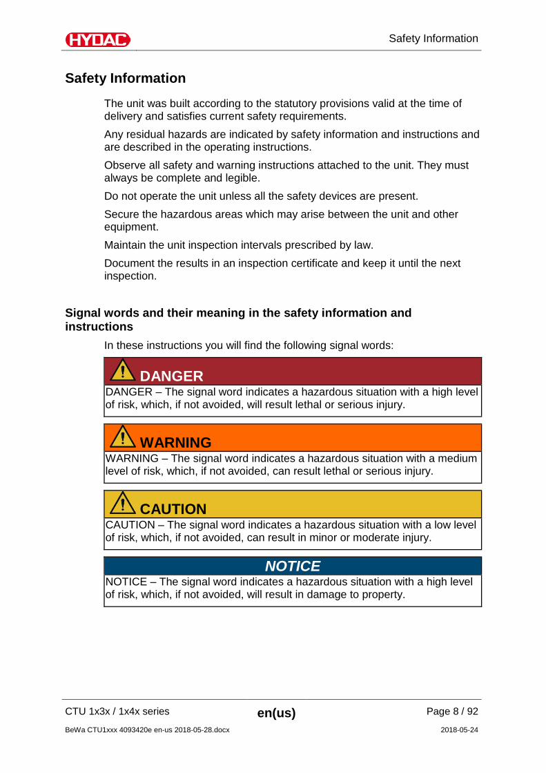
Signal words and their meaning in the safety information and instructions
In these instructions you will find the following signal words:
DANGER DANGER – The signal word indicates a hazardous situation with a high level of risk, which, if not avoided, will result lethal or serious injury.
WARNING WARNING – The signal word indicates a hazardous situation with a medium level of risk, which, if not avoided, can result lethal or serious injury.
CAUTION CAUTION – The signal word indicates a hazardous situation with a low level of risk, which, if not avoided, can result in minor or moderate injury.
NOTICE NOTICE – The signal word indicates a hazardous situation with a high level of risk, which, if not avoided, will result in damage to property.
Safety Information
CTU 1x3x / 1x4x series en(us) Page 9 / 92
BeWa CTU1xxx 4093420e en-us 2018-05-28.docx 2018-05-24
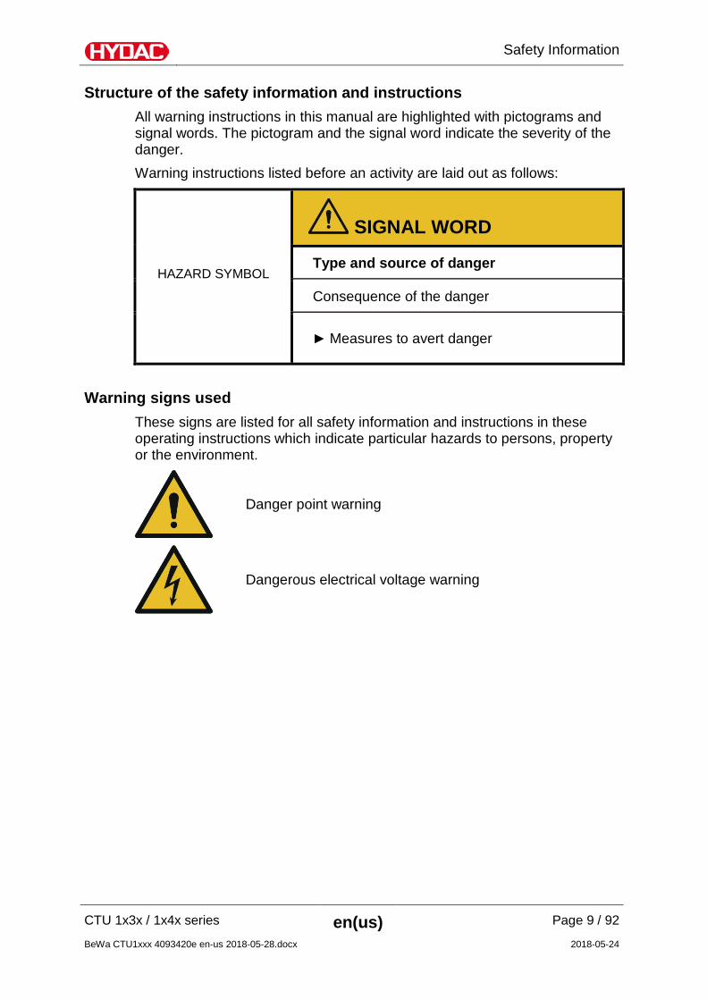
Structure of the safety information and instructions All warning instructions in this manual are highlighted with pictograms and signal words. The pictogram and the signal word indicate the severity of the danger. Warning instructions listed before an activity are laid out as follows:
HAZARD SYMBOL
SIGNAL WORD
Type and source of danger
Consequence of the danger
Measures to avert danger
Warning signs used These signs are listed for all safety information and instructions in these operating instructions which indicate particular hazards to persons, property or the environment.
Danger point warning
Dangerous electrical voltage warning
Safety Information
CTU 1x3x / 1x4x series en(us) Page 10 / 92
BeWa CTU1xxx 4093420e en-us 2018-05-28.docx 2018-05-24
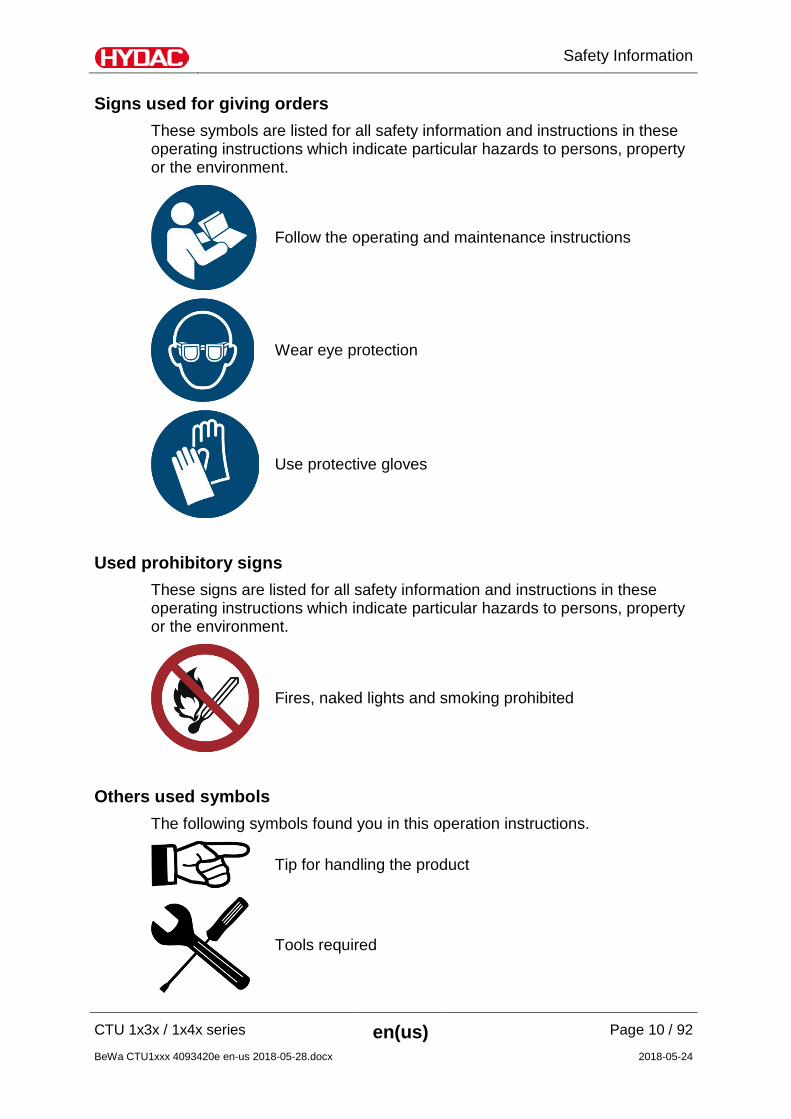
Signs used for giving orders These symbols are listed for all safety information and instructions in these operating instructions which indicate particular hazards to persons, property or the environment.
Follow the operating and maintenance instructions
Wear eye protection
Use protective gloves
Used prohibitory signs These signs are listed for all safety information and instructions in these operating instructions which indicate particular hazards to persons, property or the environment.
Fires, naked lights and smoking prohibited
Others used symbols The following symbols found you in this operation instructions.
Tip for handling the product
Tools required
Safety Information
CTU 1x3x / 1x4x series en(us) Page 11 / 92
BeWa CTU1xxx 4093420e en-us 2018-05-28.docx 2018-05-24
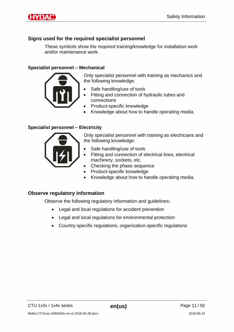
Signs used for the required specialist personnel These symbols show the required training/knowledge for installation work and/or maintenance work.
Specialist personnel – Mechanical
Only specialist personnel with training as mechanics and the following knowledge:
• Safe handling/use of tools • Fitting and connection of hydraulic tubes and
connections • Product-specific knowledge • Knowledge about how to handle operating media.
Specialist personnel – Electricity
Only specialist personnel with training as electricians and the following knowledge:
• Safe handling/use of tools • Fitting and connection of electrical lines, electrical
machinery, sockets, etc. • Checking the phase sequence • Product-specific knowledge • Knowledge about how to handle operating media.
Observe regulatory information Observe the following regulatory information and guidelines:
• Legal and local regulations for accident prevention
• Legal and local regulations for environmental protection
• Country-specific regulations, organization-specific regulations
Safety Information
CTU 1x3x / 1x4x series en(us) Page 12 / 92
BeWa CTU1xxx 4093420e en-us 2018-05-28.docx 2018-05-24
Proper/Designated Use Claims for defects or liability, regardless of the legal foundation, do not apply with incorrect or improper installation, commissioning, usage, handling, storage, maintenance, repair, use of unsuitable components or other circumstances for which HYDAC is not responsible. HYDAC is not responsible for the installation, integration, selection of interfaces to / into your system nor for the use or functionality of your system. Use the unit only for the application described in the following. The ContaminationTest Unit CTU is a test bench for analyzing the technical cleanliness of components and systems in accordance with directive VDA 19 (ISO 16232 or 18413).
DANGER
Only with soluble test liquid: "G 60 Spezial" Flammable gas-air mixture in the analysis chamber, risk of ignition and fire
Danger of fatal injury from burns
Open fires and smoking are prohibited.
NOTICE
Test liquids that cannot be used
The CTU can be damaged.
Use only test liquids which are compatible with the materials and the sealing materials they come in contact with.
Use G60 Spezial as the test liquid. CTU 1xx1 only
Do not use completely demineralized water as a test liquid. Using water containing tensides (permissible pH values: 6 to 10) as a test liquid is permitted.
Proper or designated use of the product extends to the following: o Maintaining adherence to all the instructions contained herein.
Safety Information
CTU 1x3x / 1x4x series en(us) Page 13 / 92
BeWa CTU1xxx 4093420e en-us 2018-05-28.docx 2018-05-24
o Not operating unless the side paneling is fitted. o Not operating unless the analysis chamber is closed. o Performing requisite inspection and maintenance work. o Supervised operation.
Improper Use or Use Deviating from Intended Use Any use extending beyond this or deviating therefrom shall not be considered intended use. HYDAC Filter Systems GmbH will assume no liability for any damage resulting from such use. The user alone, shall assume any and all associated risk Improper use may result in hazards and/or will damage the unit. Improper use or use deviating from intended use are, for example:
• Operation with an impermissible test liquid.
• Operation under impermissible operating conditions.
• Operation when the safety devices are defective.
• Modifications to the power unit made by the user or purchaser.
• Inadequate monitoring of parts that are subject to wear and tear.
• Improperly performed repair work.
• Unsupervised operation.
Safety Information
CTU 1x3x / 1x4x series en(us) Page 14 / 92
BeWa CTU1xxx 4093420e en-us 2018-05-28.docx 2018-05-24
Qualifications of personnel / target group Staff who work with the powerpack must be aware of the dangers involved, must be over the age of 14 and must be without any physical impediments in regard to the industrial environment. These operating instructions are intended for: Auxiliary personnel: Such persons have been instructed about the product and informed about potential hazards that can result from improper use. Operating personnel: Such persons have been instructed in power unit operation and are aware of potential hazards due to improper use. Specialist personnel Such persons have corresponding specialist training and several years' work experience. They are able to assess and perform the work assigned to them, they are also able to recognize potential hazards. Activity Person Knowledge
Transport / storage Specialist personnel
Knowledge of transport safety required
Startup operation operations control
Specialist personnel
Product-specific knowledge required. Knowledge of how to handle test liquid required.
troubleshooting, maintenance, decommissioning, Disassembly
Specialist personnel
Safe handling/use of tools. Product-specific knowledge required.
Disposal Specialist personnel
Knowledge of environmentally-friendly disposal of materials and matter is required. Knowledge of decontamination of contaminants is required. Knowledge with regard to recycling is required.
Safety Information
CTU 1x3x / 1x4x series en(us) Page 15 / 92
BeWa CTU1xxx 4093420e en-us 2018-05-28.docx 2018-05-24
Wear suitable clothing Loose-fitting clothing increases the risk of being caught or being drawn in on rotating parts, and the risk of getting caught on protruding parts. You can be severely injured or killed.
• Wear close-fitting clothing.
• Do not wear any rings, chains or any other jewelry.
• Wear work safety shoes.
• Wear gloves.
• Observe the information relating to personal protection equipment in the safety data sheet of the operating fluid.
Observe regulatory information Observe the following regulatory information and guidelines:
• Legal and local regulations for accident prevention
• Legal and local regulations for environmental protection
• Country-specific regulations, organization-specific regulations
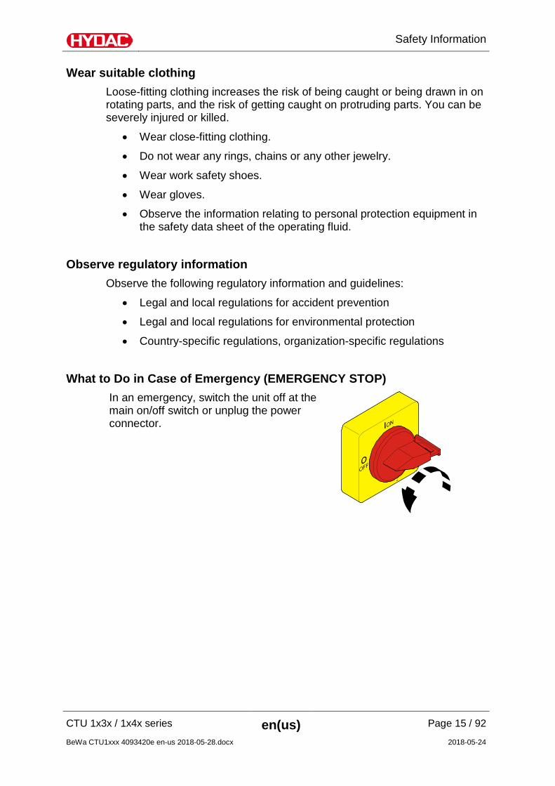
What to Do in Case of Emergency (EMERGENCY STOP) In an emergency, switch the unit off at the main on/off switch or unplug the power connector.
Transporting assembly
CTU 1x3x / 1x4x series en(us) Page 16 / 92
BeWa CTU1xxx 4093420e en-us 2018-05-28.docx 2018-05-24
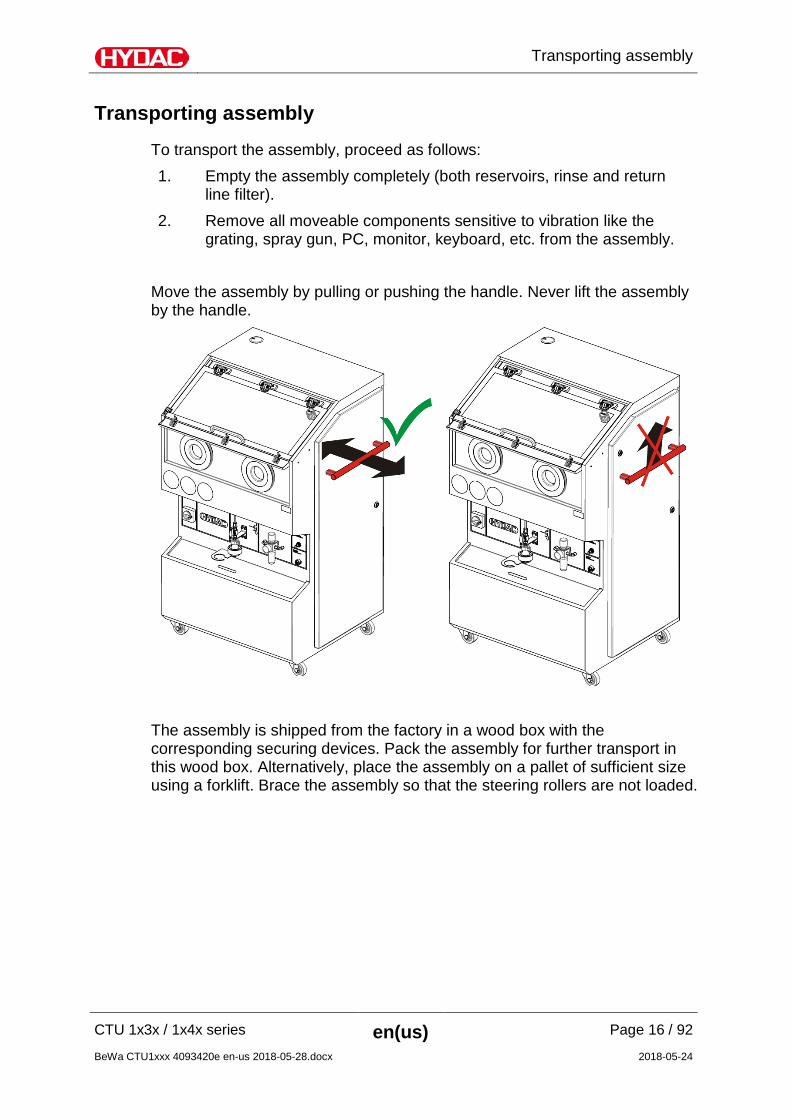
Transporting assembly
To transport the assembly, proceed as follows: 1. Empty the assembly completely (both reservoirs, rinse and return
line filter). 2. Remove all moveable components sensitive to vibration like the
grating, spray gun, PC, monitor, keyboard, etc. from the assembly. Move the assembly by pulling or pushing the handle. Never lift the assembly by the handle.
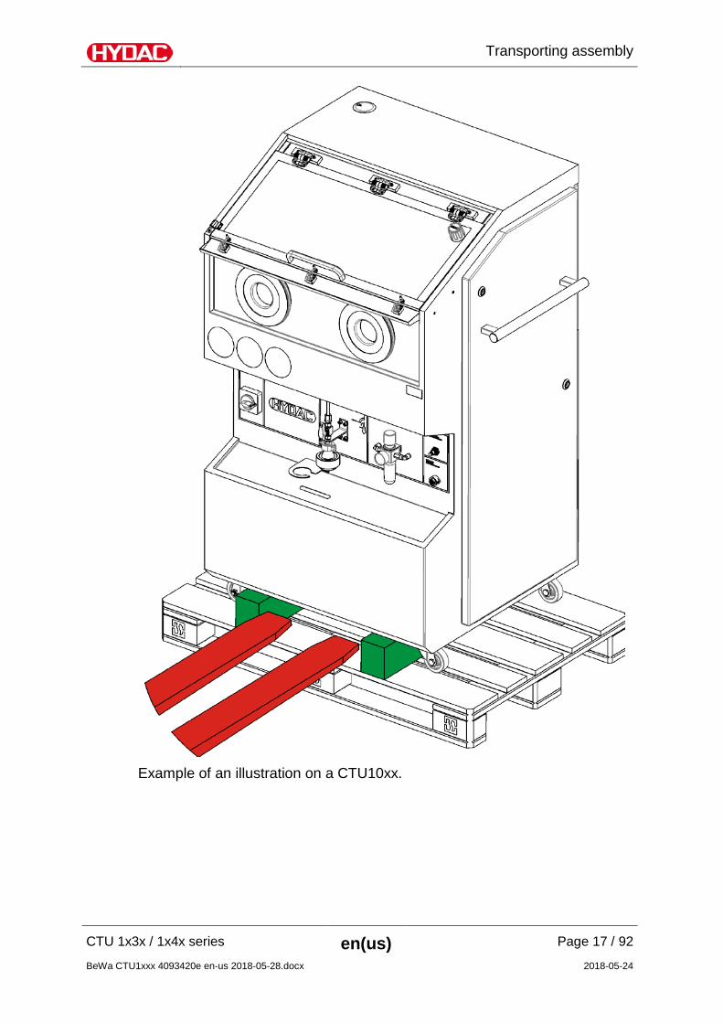
The assembly is shipped from the factory in a wood box with the corresponding securing devices. Pack the assembly for further transport in this wood box. Alternatively, place the assembly on a pallet of sufficient size using a forklift. Brace the assembly so that the steering rollers are not loaded.
Transporting assembly
CTU 1x3x / 1x4x series en(us) Page 17 / 92
BeWa CTU1xxx 4093420e en-us 2018-05-28.docx 2018-05-24
Example of an illustration on a CTU10xx.
Transporting assembly
CTU 1x3x / 1x4x series en(us) Page 18 / 92
BeWa CTU1xxx 4093420e en-us 2018-05-28.docx 2018-05-24
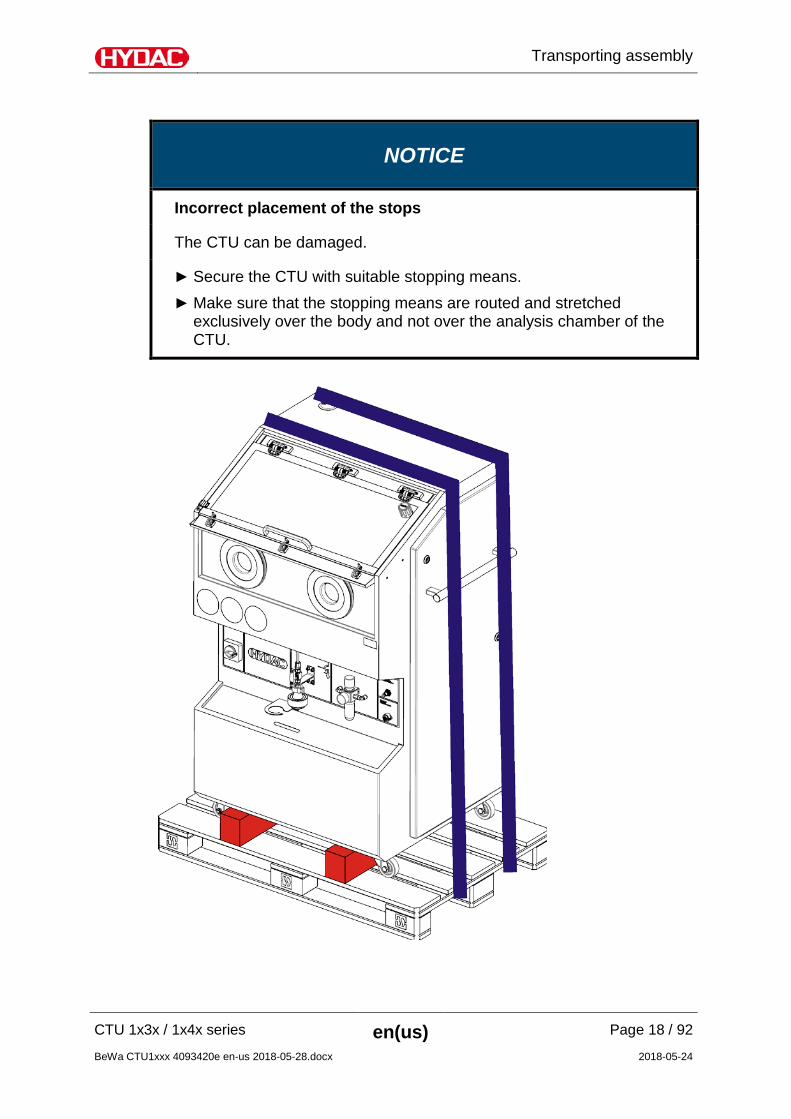
NOTICE
Incorrect placement of the stops
The CTU can be damaged.
Secure the CTU with suitable stopping means. Make sure that the stopping means are routed and stretched
exclusively over the body and not over the analysis chamber of the CTU.
Storing the assembly
CTU 1x3x / 1x4x series en(us) Page 19 / 92
BeWa CTU1xxx 4093420e en-us 2018-05-28.docx 2018-05-24
Storing the assembly
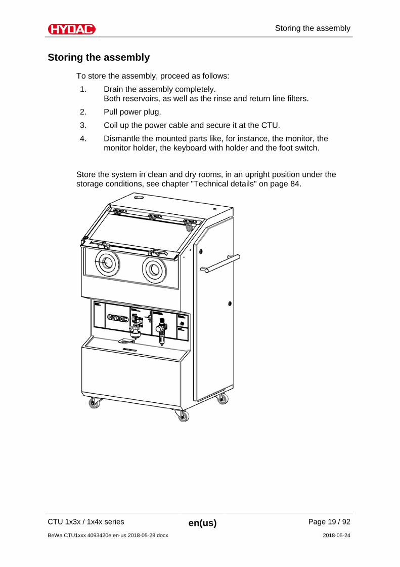
To store the assembly, proceed as follows: 1. Drain the assembly completely.
Both reservoirs, as well as the rinse and return line filters. 2. Pull power plug. 3. Coil up the power cable and secure it at the CTU. 4. Dismantle the mounted parts like, for instance, the monitor, the
monitor holder, the keyboard with holder and the foot switch. Store the system in clean and dry rooms, in an upright position under the storage conditions, see chapter "Technical details" on page 84.
Decoding the model code label
CTU 1x3x / 1x4x series en(us) Page 20 / 92
BeWa CTU1xxx 4093420e en-us 2018-05-28.docx 2018-05-24
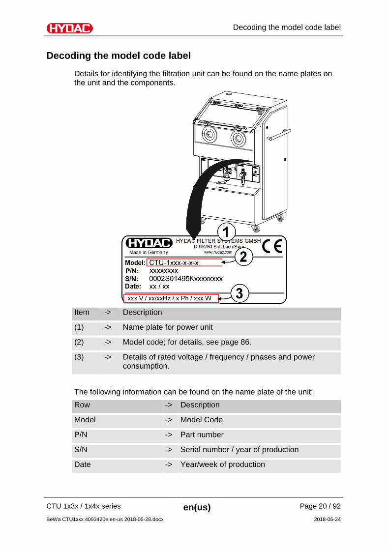
Decoding the model code label
Details for identifying the filtration unit can be found on the name plates on the unit and the components.
Item -> Description
(1) -> Name plate for power unit
(2) -> Model code; for details, see page 86.
(3) -> Details of rated voltage / frequency / phases and power consumption.
The following information can be found on the name plate of the unit: Row -> Description
Model -> Model Code
P/N -> Part number
S/N -> Serial number / year of production
Date -> Year/week of production
Checking the scope of delivery
CTU 1x3x / 1x4x series en(us) Page 21 / 92
BeWa CTU1xxx 4093420e en-us 2018-05-28.docx 2018-05-24
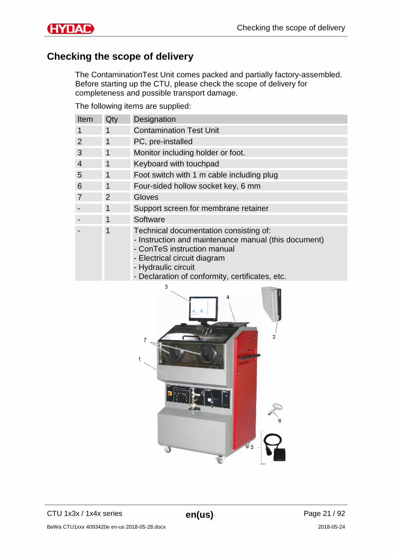
Checking the scope of delivery
The ContaminationTest Unit comes packed and partially factory-assembled. Before starting up the CTU, please check the scope of delivery for completeness and possible transport damage. The following items are supplied: Item Qty Designation 1 1 Contamination Test Unit 2 1 PC, pre-installed 3 1 Monitor including holder or foot. 4 1 Keyboard with touchpad 5 1 Foot switch with 1 m cable including plug 6 1 Four-sided hollow socket key, 6 mm
7 2 Gloves - 1 Support screen for membrane retainer - 1 Software - 1 Technical documentation consisting of:
- Instruction and maintenance manual (this document) - ConTeS instruction manual - Electrical circuit diagram - Hydraulic circuit - Declaration of conformity, certificates, etc.
CTU Dimensions
CTU 1x3x / 1x4x series en(us) Page 22 / 92
BeWa CTU1xxx 4093420e en-us 2018-05-28.docx 2018-05-24
CTU Dimensions
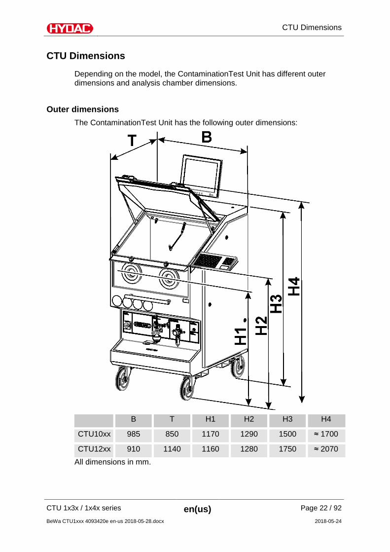
Depending on the model, the ContaminationTest Unit has different outer dimensions and analysis chamber dimensions.
Outer dimensions The ContaminationTest Unit has the following outer dimensions:
B T H1 H2 H3 H4
CTU10xx 985 850 1170 1290 1500 ≈ 1700
CTU12xx 910 1140 1160 1280 1750 ≈ 2070 All dimensions in mm.
CTU Dimensions
CTU 1x3x / 1x4x series en(us) Page 23 / 92
BeWa CTU1xxx 4093420e en-us 2018-05-28.docx 2018-05-24
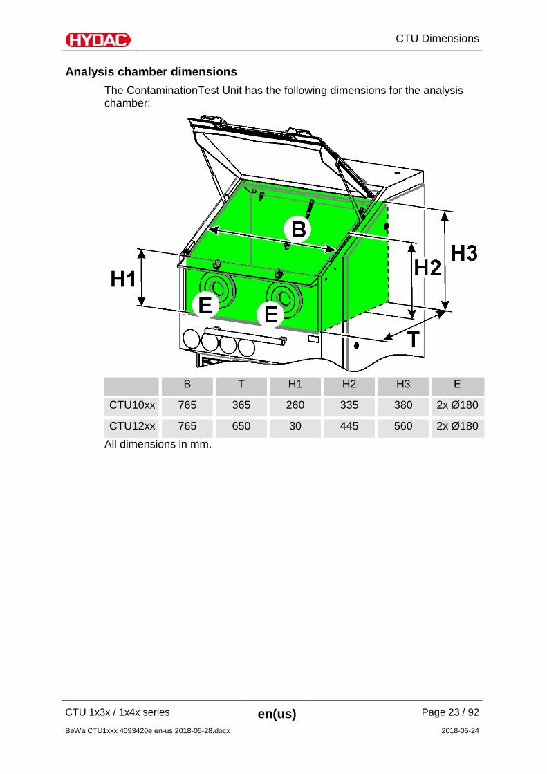
Analysis chamber dimensions The ContaminationTest Unit has the following dimensions for the analysis chamber:
B T H1 H2 H3 E
CTU10xx 765 365 260 335 380 2x Ø180
CTU12xx 765 650 30 445 560 2x Ø180 All dimensions in mm.
Preparing the CTU for operation
CTU 1x3x / 1x4x series en(us) Page 24 / 92
BeWa CTU1xxx 4093420e en-us 2018-05-28.docx 2018-05-24
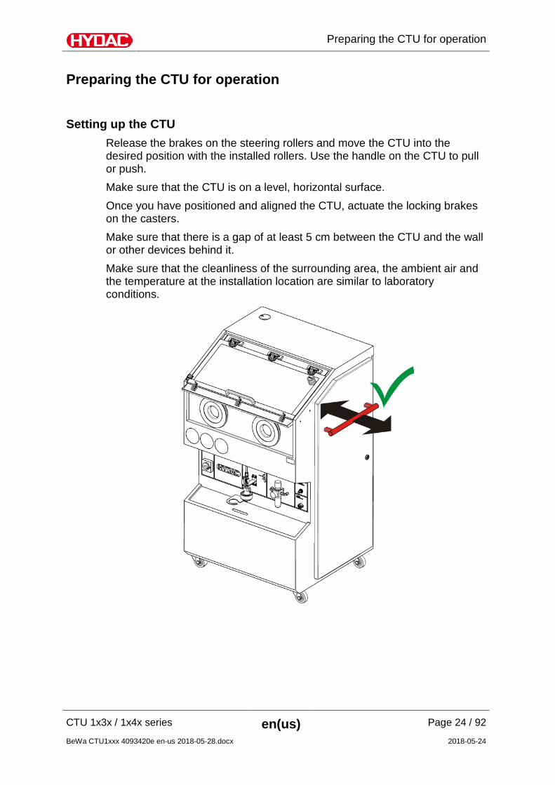
Preparing the CTU for operation
Setting up the CTU Release the brakes on the steering rollers and move the CTU into the desired position with the installed rollers. Use the handle on the CTU to pull or push. Make sure that the CTU is on a level, horizontal surface. Once you have positioned and aligned the CTU, actuate the locking brakes on the casters. Make sure that there is a gap of at least 5 cm between the CTU and the wall or other devices behind it. Make sure that the cleanliness of the surrounding area, the ambient air and the temperature at the installation location are similar to laboratory conditions.
Preparing the CTU for operation
CTU 1x3x / 1x4x series en(us) Page 25 / 92
BeWa CTU1xxx 4093420e en-us 2018-05-28.docx 2018-05-24
Putting the CTU into operation The following personnel with the corresponding expertise is required to start up the CTU.
Only specialist personnel with training as electricians and the following knowledge:
• Safe handling/use of tools • Fitting and connection of electrical lines, electrical
machinery, sockets, etc. • Checking the phase sequence • Product-specific knowledge • Knowledge about how to handle operating media.
Checking connections and contacts
DANGER
Dangerous electrical voltage warning
Danger of fatal injury
Any work involving the power supply may only be done by a properly trained, certified electrician.
Remove the power plug before undertaking any work.
Install or check the following points before commissioning:
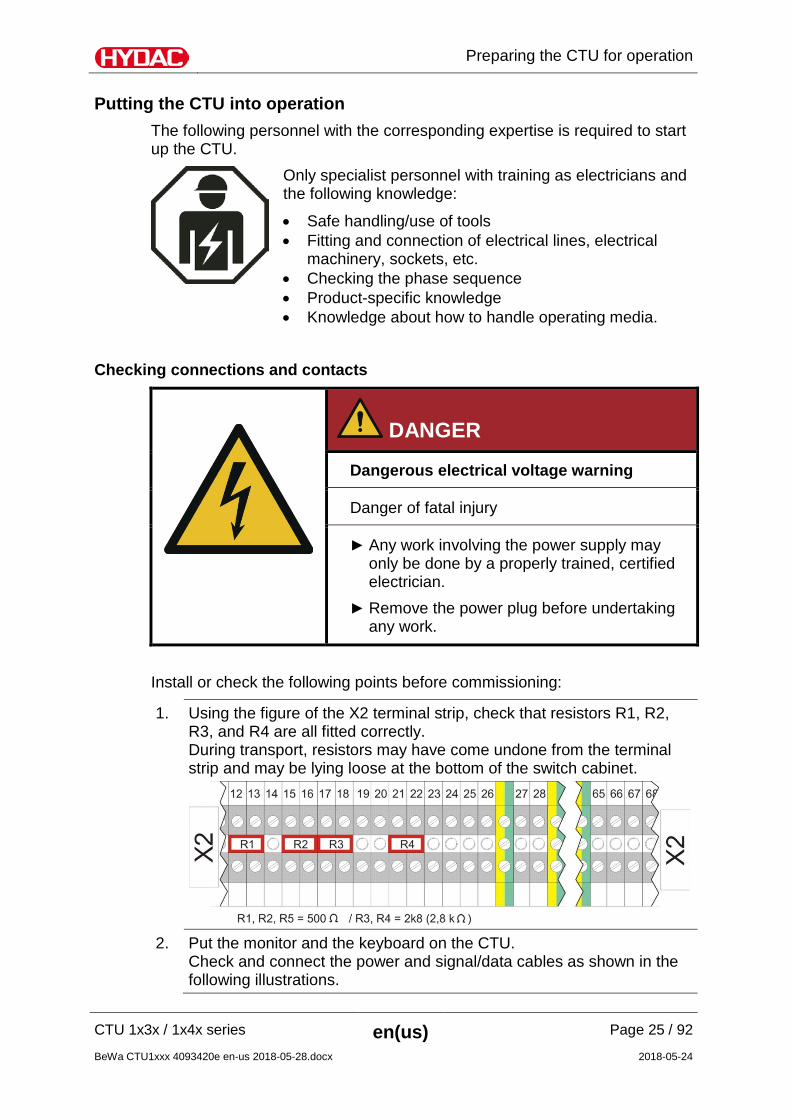
1. Using the figure of the X2 terminal strip, check that resistors R1, R2, R3, and R4 are all fitted correctly. During transport, resistors may have come undone from the terminal strip and may be lying loose at the bottom of the switch cabinet.
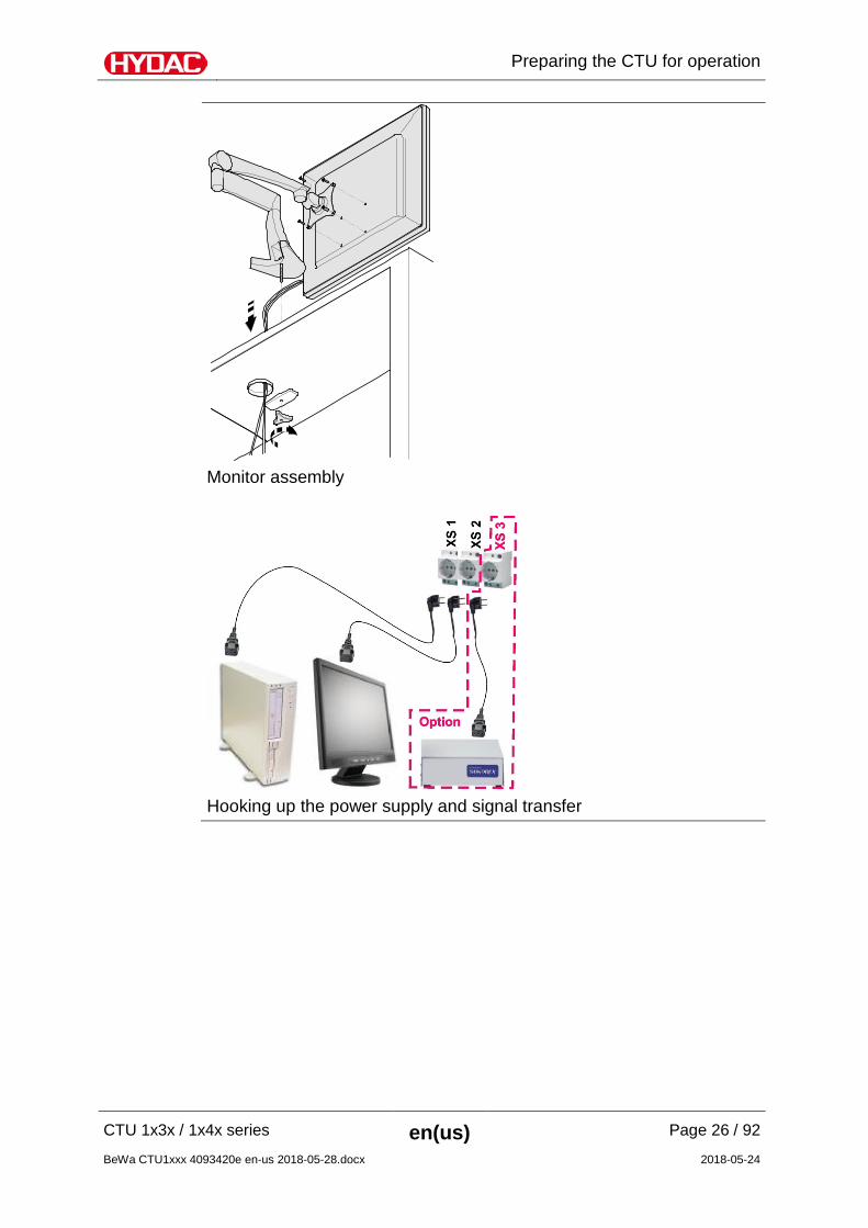
2. Put the monitor and the keyboard on the CTU.
Check and connect the power and signal/data cables as shown in the following illustrations.
Preparing the CTU for operation
CTU 1x3x / 1x4x series en(us) Page 26 / 92
BeWa CTU1xxx 4093420e en-us 2018-05-28.docx 2018-05-24
Monitor assembly
Hooking up the power supply and signal transfer

Preparing the CTU for operation
CTU 1x3x / 1x4x series en(us) Page 27 / 92
BeWa CTU1xxx 4093420e en-us 2018-05-28.docx 2018-05-24
Connecting the Connector Cables
3. Install the gloves supplied (see page 75 for more details). If the gloves have already been installed, check that they are properly seated.
4. Take the sticker "Clean cover using only a moist cloth" supplied in your language, and fix it to the lower right part of the border film on the see-through door.
5. Take the support sieve supplied and put it in the membrane holder.
6. Check that the drain valve is set to its normal operating position, correcting if necessary. See page 67 for details.
7. Fill the CTU with test liquid. See page 69 for details
8. Clean the analysis chamber by using the rinsing of the inner chamber and the spray gun until a negative control value is achieved as listed in the table on page 37. Experience shows that at least 12 rinsing cycles, using approx. 15 liters, will be required.
9. Commissioning is completed.
Air extraction within the unit
CTU 1x3x / 1x4x series en(us) Page 28 / 92
BeWa CTU1xxx 4093420e en-us 2018-05-28.docx 2018-05-24
Air extraction within the unit
Air extraction within the unit is required if:
• the chemical composition of the test liquid used specifies it
• there is no ventilation and/or air conditioning in the CTU operating room
• an easily volatile test liquid is used Check the Safety Data Sheet of the test liquid. During extraction, observe the required volumetric flow and check for proper wiring in the entire space ventilation equipment.
Note when using the test liquid G 60 Spezial
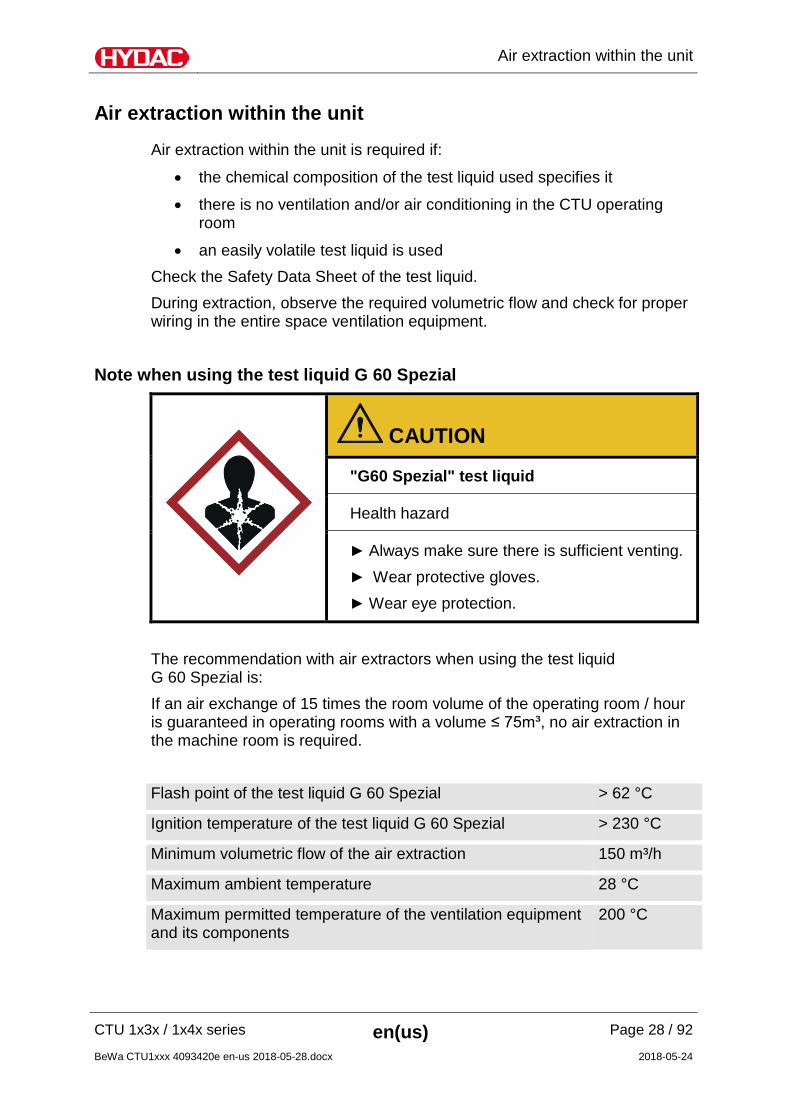
CAUTION
"G60 Spezial" test liquid
Health hazard
Always make sure there is sufficient venting. Wear protective gloves. Wear eye protection.
The recommendation with air extractors when using the test liquid G 60 Spezial is: If an air exchange of 15 times the room volume of the operating room / hour is guaranteed in operating rooms with a volume ≤ 75m³, no air extraction in the machine room is required. Flash point of the test liquid G 60 Spezial > 62 °C
Ignition temperature of the test liquid G 60 Spezial > 230 °C
Minimum volumetric flow of the air extraction 150 m³/h
Maximum ambient temperature 28 °C
Maximum permitted temperature of the ventilation equipment and its components
200 °C

Air extraction within the unit
CTU 1x3x / 1x4x series en(us) Page 29 / 92
BeWa CTU1xxx 4093420e en-us 2018-05-28.docx 2018-05-24
Connecting an air extractor The scope of delivery and the type of extraction vary depending on the model. Please note the following descriptions for the respective model.
Suctioning the machine room of the CTU 1x3x If there is an air extraction system at the installation location, this can be attached to the connection on the rear side of the CTU. The air exhaust port is sealed with a cover at the time of delivery of the CTU 1x3x. Only in the unit is the air extracted using this connection.
Air extraction within the unit
CTU 1x3x / 1x4x series en(us) Page 30 / 92
BeWa CTU1xxx 4093420e en-us 2018-05-28.docx 2018-05-24
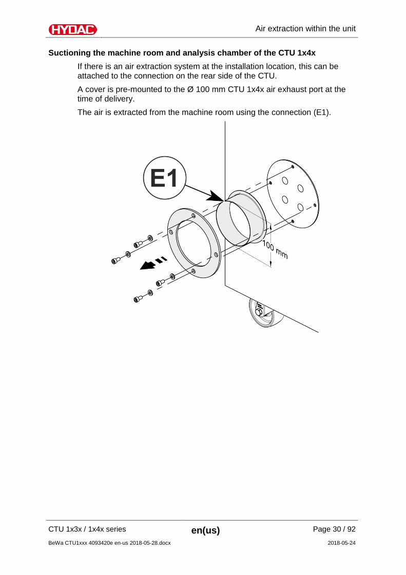
Suctioning the machine room and analysis chamber of the CTU 1x4x If there is an air extraction system at the installation location, this can be attached to the connection on the rear side of the CTU. A cover is pre-mounted to the Ø 100 mm CTU 1x4x air exhaust port at the time of delivery. The air is extracted from the machine room using the connection (E1).
Air extraction within the unit
CTU 1x3x / 1x4x series en(us) Page 31 / 92
BeWa CTU1xxx 4093420e en-us 2018-05-28.docx 2018-05-24
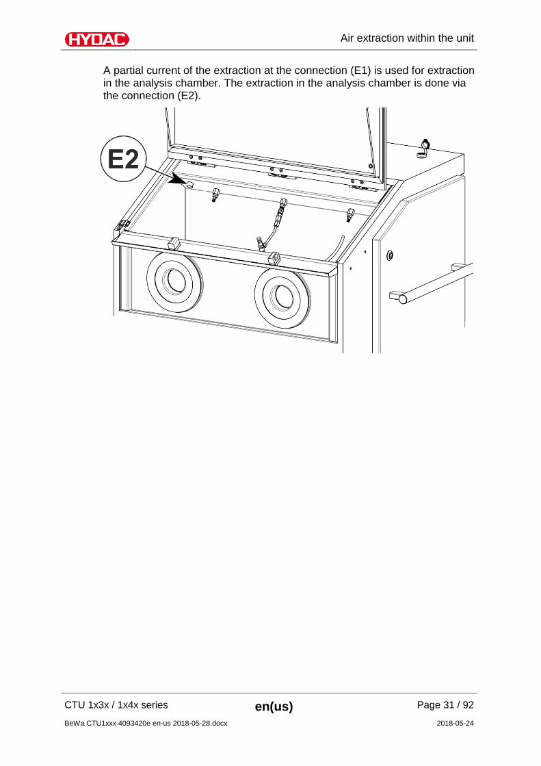
A partial current of the extraction at the connection (E1) is used for extraction in the analysis chamber. The extraction in the analysis chamber is done via the connection (E2).
Air extraction within the unit
CTU 1x3x / 1x4x series en(us) Page 32 / 92
BeWa CTU1xxx 4093420e en-us 2018-05-28.docx 2018-05-24
Setting up the electrical connection of the CTU The device is supplied with a power plug fitted.
DANGER
Electric shock
Danger of fatal injury as a result of electrical voltage
The CTU may only be connected to a power outlet with a ground connection.
Before plugging the CTU into the power socket, make sure that the voltage available corresponds to that specified on its type label.
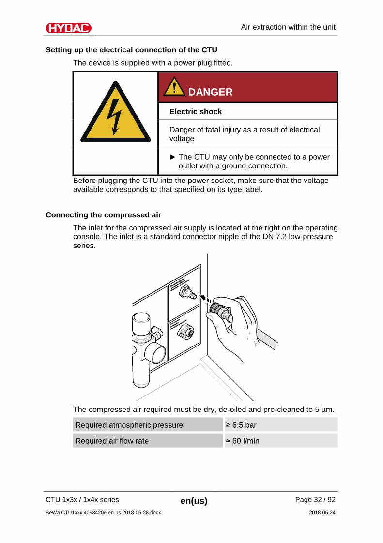
Connecting the compressed air The inlet for the compressed air supply is located at the right on the operating console. The inlet is a standard connector nipple of the DN 7.2 low-pressure series.
The compressed air required must be dry, de-oiled and pre-cleaned to 5 µm.
Required atmospheric pressure ≥ 6.5 bar
Required air flow rate ≈ 60 l/min
Air extraction within the unit
CTU 1x3x / 1x4x series en(us) Page 33 / 92
BeWa CTU1xxx 4093420e en-us 2018-05-28.docx 2018-05-24
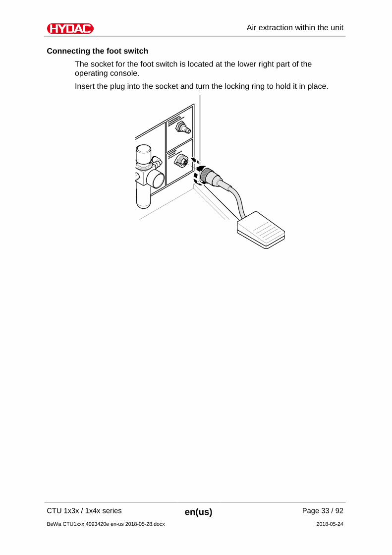
Connecting the foot switch The socket for the foot switch is located at the lower right part of the operating console. Insert the plug into the socket and turn the locking ring to hold it in place.
Parts of the CTU
CTU 1x3x / 1x4x series en(us) Page 34 / 92
BeWa CTU1xxx 4093420e en-us 2018-05-28.docx 2018-05-24
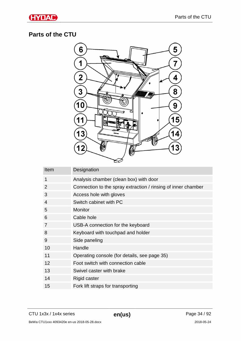
Parts of the CTU
Item Designation
1 Analysis chamber (clean box) with door 2 Connection to the spray extraction / rinsing of inner chamber 3 Access hole with gloves 4 Switch cabinet with PC 5 Monitor 6 Cable hole 7 USB-A connection for the keyboard 8 Keyboard with touchpad and holder 9 Side paneling 10 Handle 11 Operating console (for details, see page 35) 12 Foot switch with connection cable 13 Swivel caster with brake 14 Rigid caster 15 Fork lift straps for transporting
Parts of the CTU
CTU 1x3x / 1x4x series en(us) Page 35 / 92
BeWa CTU1xxx 4093420e en-us 2018-05-28.docx 2018-05-24
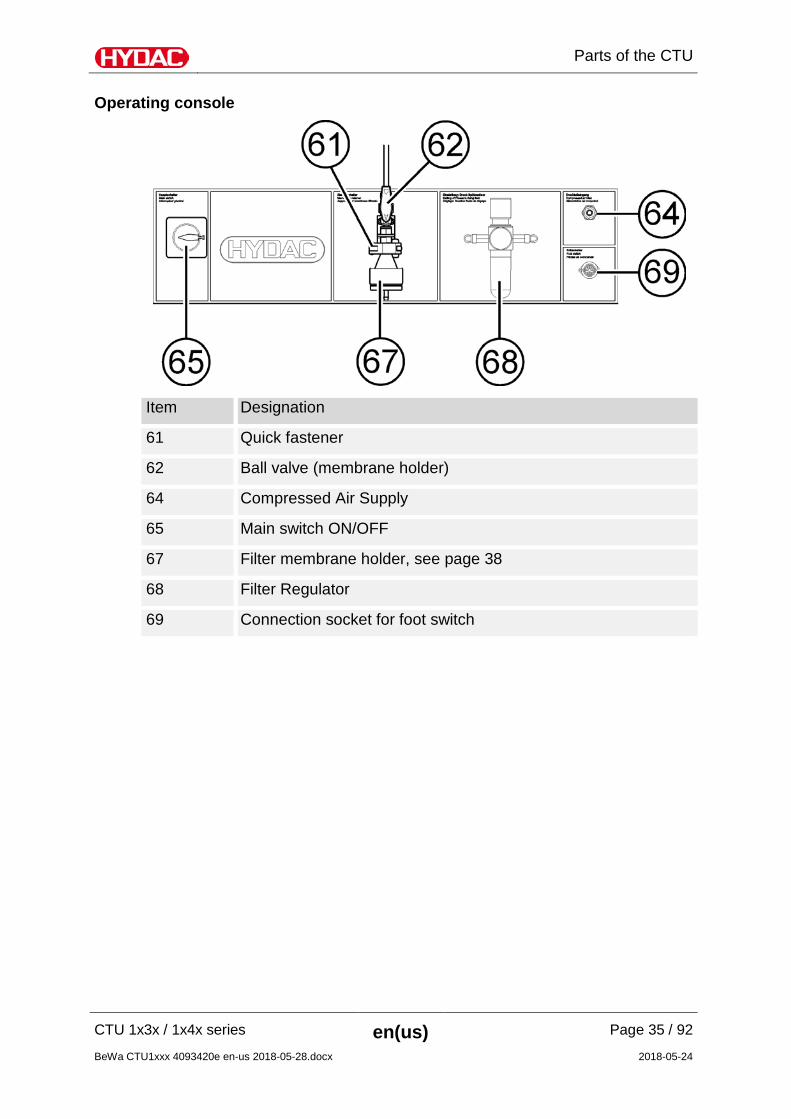
Operating console
Item Designation
61 Quick fastener
62 Ball valve (membrane holder)
64 Compressed Air Supply
65 Main switch ON/OFF
67 Filter membrane holder, see page 38
68 Filter Regulator
69 Connection socket for foot switch
Functional principle
CTU 1x3x / 1x4x series en(us) Page 36 / 92
BeWa CTU1xxx 4093420e en-us 2018-05-28.docx 2018-05-24
Functional principle
The CTU is a specially designed test bench for analyzing the surface cleanliness of components. These components are rinsed off in a clean environment using a test liquid with a defined cleanliness. The particles carried by the test liquid are collected on a membrane for subsequent analysis. The results provide information on the type, size and mass of contamination. Knowing what type of contamination is involved enables measurements to be taken to prevent it (improved filtration, transportation, storage, etc.).
Manual spray extraction Place the component to be analyzed in the analysis chamber (1). After entering the required analysis parameters via the the user interface, press the foot switch to pump the test liquid from reservoir B1 into the analysis chamber (1) via the fine filter, the 2/2 directional valve and the spray gun with nozzle. The operator has to make sure that the surfaces of the component to be analyzed are evenly flushed. The test liquid, (now called the analysis liquid) carrying some of the particles washed off of the component, is sucked through the analysis membrane and flows back into the reservoir B2. The vacuum is created by a vacuum nozzle using the Venturi principle. The level in the reservoirs B1 and B2 is constantly monitored using level sensors. When the lower fill level is reached in one reservoir, switchover automatically takes place between reservoir B1 and reservoir B2. The quantity of test liquid in the analysis chamber (1) is determined by a flow rate meter. Directional valve is closed once the preset quantity has been conveyed. Wait until the analysis fluid has been completely sucked through the membrane. Then remove the analysis membrane and evaluate it.
Functional principle
CTU 1x3x / 1x4x series en(us) Page 37 / 92
BeWa CTU1xxx 4093420e en-us 2018-05-28.docx 2018-05-24
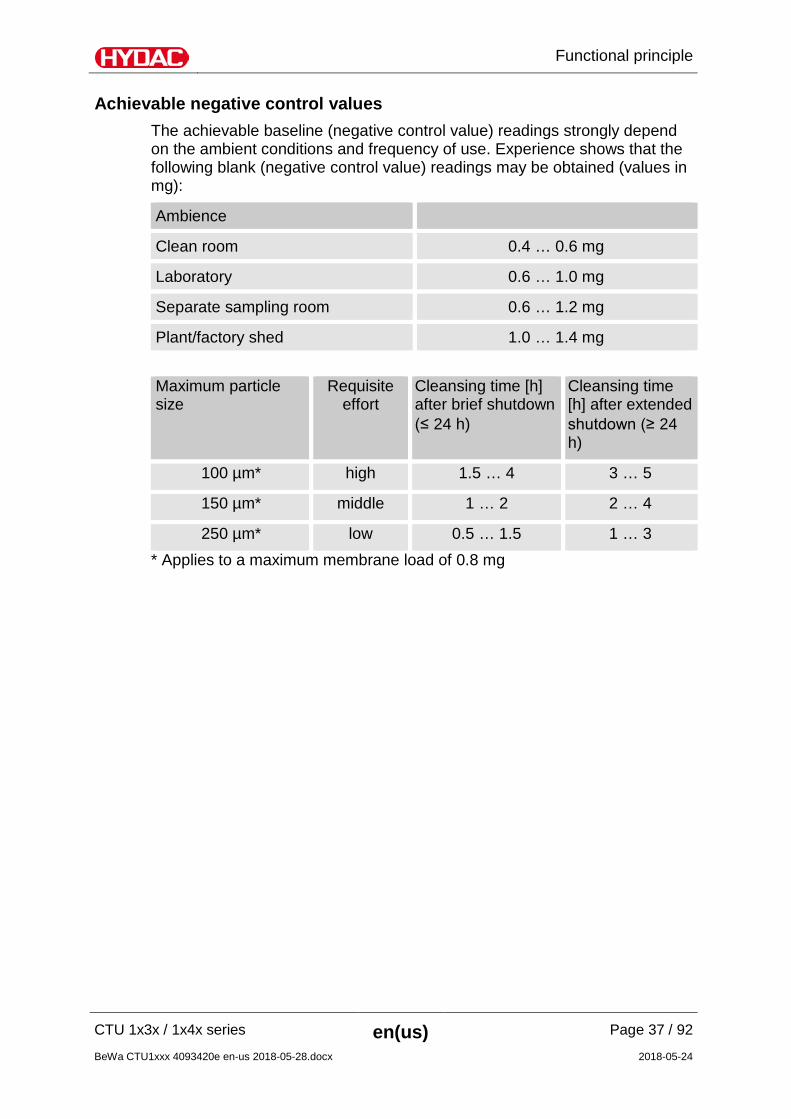
Achievable negative control values The achievable baseline (negative control value) readings strongly depend on the ambient conditions and frequency of use. Experience shows that the following blank (negative control value) readings may be obtained (values in mg):
Ambience
Clean room 0.4 … 0.6 mg
Laboratory 0.6 … 1.0 mg
Separate sampling room 0.6 … 1.2 mg
Plant/factory shed 1.0 … 1.4 mg Maximum particle size
Requisite effort
Cleansing time [h] after brief shutdown (≤ 24 h)
Cleansing time [h] after extended shutdown (≥ 24 h)
100 µm* high 1.5 … 4 3 … 5
150 µm* middle 1 … 2 2 … 4
250 µm* low 0.5 … 1.5 1 … 3 * Applies to a maximum membrane load of 0.8 mg

Operating filter membrane holder / Removing filter membrane
CTU 1x3x / 1x4x series en(us) Page 38 / 92
BeWa CTU1xxx 4093420e en-us 2018-05-28.docx 2018-05-24
Operating filter membrane holder / Removing filter membrane
The operation of the filter membrane holder changes depending on the version and model. Descriptions of the versions are given below.
Filter membrane holder with union nut The thread on the union nut means that the lower part (67.2) of the membrane holder is pressed against the upper part (67.1) preventing leakage and ensuring that the membrane works properly.
To close the filter membrane holder, lift the lower part (2) up to the upper part and tighten the union nut (1) clockwise. Do not use a tool. The filter membrane holder is opened by turning the union nut (1) counter-clockwise.
Operating filter membrane holder / Removing filter membrane
CTU 1x3x / 1x4x series en(us) Page 39 / 92
BeWa CTU1xxx 4093420e en-us 2018-05-28.docx 2018-05-24
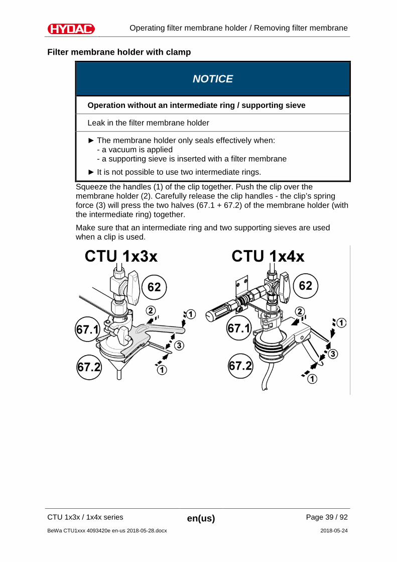
Filter membrane holder with clamp
NOTICE
Operation without an intermediate ring / supporting sieve
Leak in the filter membrane holder
The membrane holder only seals effectively when: - a vacuum is applied - a supporting sieve is inserted with a filter membrane
It is not possible to use two intermediate rings.
Squeeze the handles (1) of the clip together. Push the clip over the membrane holder (2). Carefully release the clip handles - the clip’s spring force (3) will press the two halves (67.1 + 67.2) of the membrane holder (with the intermediate ring) together. Make sure that an intermediate ring and two supporting sieves are used when a clip is used.
Operating filter membrane holder / Removing filter membrane
CTU 1x3x / 1x4x series en(us) Page 40 / 92
BeWa CTU1xxx 4093420e en-us 2018-05-28.docx 2018-05-24
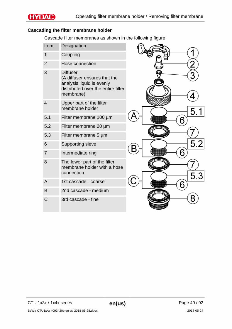
Cascading the filter membrane holder Cascade filter membranes as shown in the following figure: Item Designation
1 Coupling
2 Hose connection
3 Diffuser (A diffuser ensures that the analysis liquid is evenly distributed over the entire filter membrane)
4 Upper part of the filter membrane holder
5.1 Filter membrane 100 µm
5.2 Filter membrane 20 µm
5.3 Filter membrane 5 µm
6 Supporting sieve
7 Intermediate ring
8 The lower part of the filter membrane holder with a hose connection
A 1st cascade - coarse
B 2nd cascade - medium
C 3rd cascade - fine
Operating filter membrane holder / Removing filter membrane
CTU 1x3x / 1x4x series en(us) Page 41 / 92
BeWa CTU1xxx 4093420e en-us 2018-05-28.docx 2018-05-24
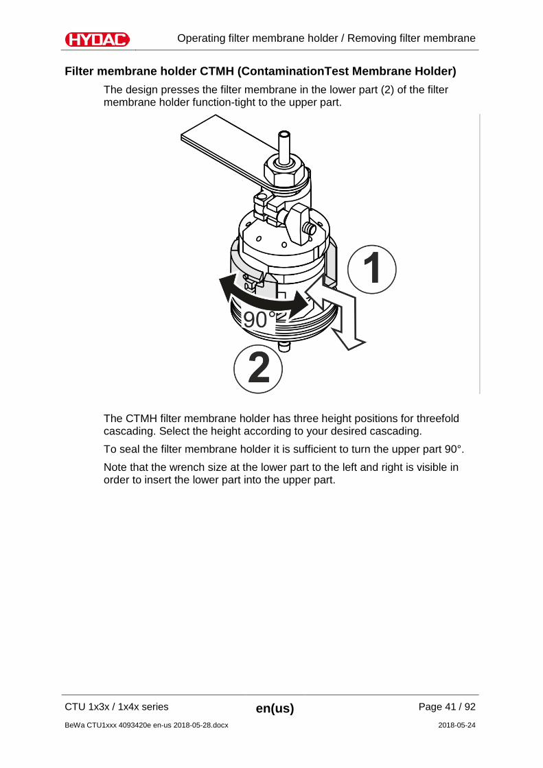
Filter membrane holder CTMH (ContaminationTest Membrane Holder) The design presses the filter membrane in the lower part (2) of the filter membrane holder function-tight to the upper part.
The CTMH filter membrane holder has three height positions for threefold cascading. Select the height according to your desired cascading. To seal the filter membrane holder it is sufficient to turn the upper part 90°. Note that the wrench size at the lower part to the left and right is visible in order to insert the lower part into the upper part.
Operating filter membrane holder / Removing filter membrane
CTU 1x3x / 1x4x series en(us) Page 42 / 92
BeWa CTU1xxx 4093420e en-us 2018-05-28.docx 2018-05-24
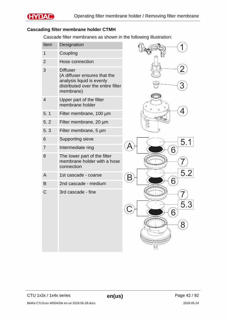
Cascading filter membrane holder CTMH Cascade filter membranes as shown in the following illustration: Item Designation
1 Coupling
2 Hose connection
3 Diffuser (A diffuser ensures that the analysis liquid is evenly distributed over the entire filter membrane)
4 Upper part of the filter membrane holder
5. 1 Filter membrane, 100 µm
5. 2 Filter membrane, 20 µm
5. 3 Filter membrane, 5 µm
6 Supporting sieve
7 Intermediate ring
8 The lower part of the filter membrane holder with a hose connection
A 1st cascade - coarse
B 2nd cascade - medium
C 3rd cascade - fine
Operating filter membrane holder / Removing filter membrane
CTU 1x3x / 1x4x series en(us) Page 43 / 92
BeWa CTU1xxx 4093420e en-us 2018-05-28.docx 2018-05-24
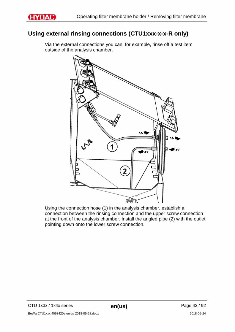
Using external rinsing connections (CTU1xxx-x-x-R only)
Via the external connections you can, for example, rinse off a test item outside of the analysis chamber.
Using the connection hose (1) in the analysis chamber, establish a connection between the rinsing connection and the upper screw connection at the front of the analysis chamber. Install the angled pipe (2) with the outlet pointing down onto the lower screw connection.
Operating filter membrane holder / Removing filter membrane
CTU 1x3x / 1x4x series en(us) Page 44 / 92
BeWa CTU1xxx 4093420e en-us 2018-05-28.docx 2018-05-24
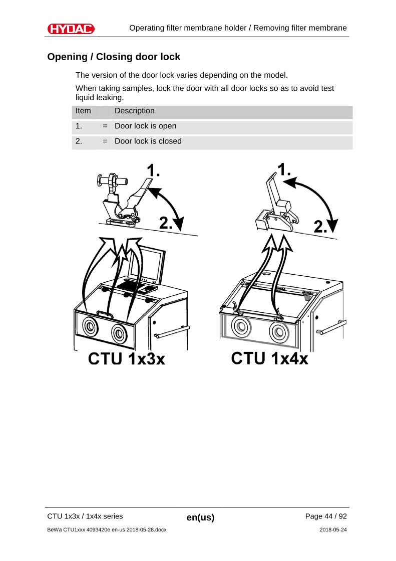
Opening / Closing door lock
The version of the door lock varies depending on the model. When taking samples, lock the door with all door locks so as to avoid test liquid leaking. Item Description
1. = Door lock is open
2. = Door lock is closed
CTU during operation
CTU 1x3x / 1x4x series en(us) Page 45 / 92
BeWa CTU1xxx 4093420e en-us 2018-05-28.docx 2018-05-24
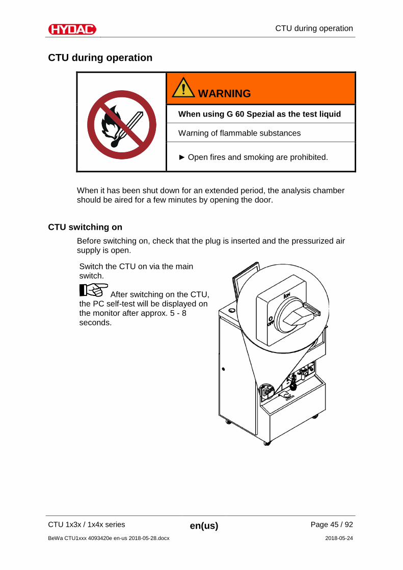
CTU during operation
WARNING
When using G 60 Spezial as the test liquid
Warning of flammable substances
Open fires and smoking are prohibited.
When it has been shut down for an extended period, the analysis chamber should be aired for a few minutes by opening the door.
CTU switching on Before switching on, check that the plug is inserted and the pressurized air supply is open.
Switch the CTU on via the main switch.
After switching on the CTU, the PC self-test will be displayed on the monitor after approx. 5 - 8 seconds.
CTU during operation
CTU 1x3x / 1x4x series en(us) Page 46 / 92
BeWa CTU1xxx 4093420e en-us 2018-05-28.docx 2018-05-24
ConTeS Software The main window of the ConTeS appears automatically after the PC has been switched on and has started up. For details on the ConTeS software, please see the "ConTeS operating instructions".
Clean-Room Conditions in the Analysis Chamber - Rinsing of the inner chamber
Clean the analysis chamber of the CTU before the beginning of a contamination test series with the "Rinsing of inner chamber" program defined by the volume or by the time/duration. During operation, as well as between extractions, make sure that the analysis chamber is always closed and is opened for only a short time for the insertion of the component to be analyzed. Only in this way can you ensure that contamination from the surrounding area is as minimal as possible.
CTU during operation
CTU 1x3x / 1x4x series en(us) Page 47 / 92
BeWa CTU1xxx 4093420e en-us 2018-05-28.docx 2018-05-24
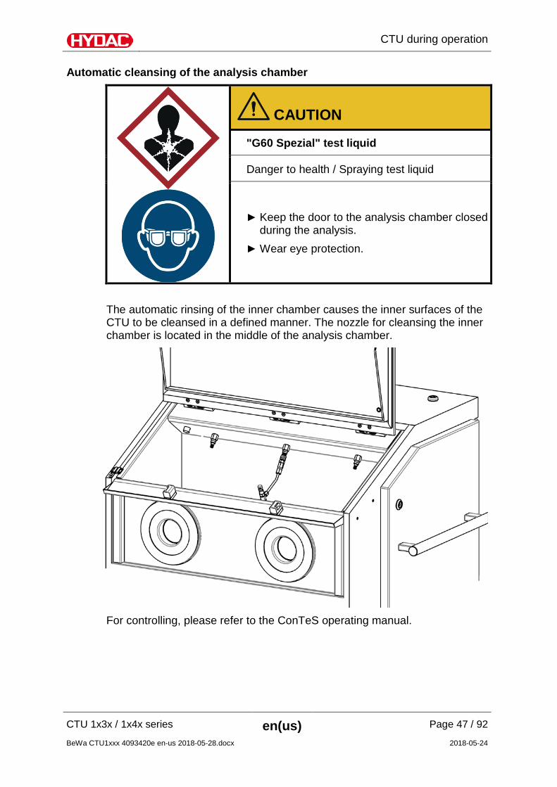
Automatic cleansing of the analysis chamber
CAUTION
"G60 Spezial" test liquid
Danger to health / Spraying test liquid
Keep the door to the analysis chamber closed during the analysis.
Wear eye protection.
The automatic rinsing of the inner chamber causes the inner surfaces of the CTU to be cleansed in a defined manner. The nozzle for cleansing the inner chamber is located in the middle of the analysis chamber.
For controlling, please refer to the ConTeS operating manual.
CTU during operation
CTU 1x3x / 1x4x series en(us) Page 48 / 92
BeWa CTU1xxx 4093420e en-us 2018-05-28.docx 2018-05-24
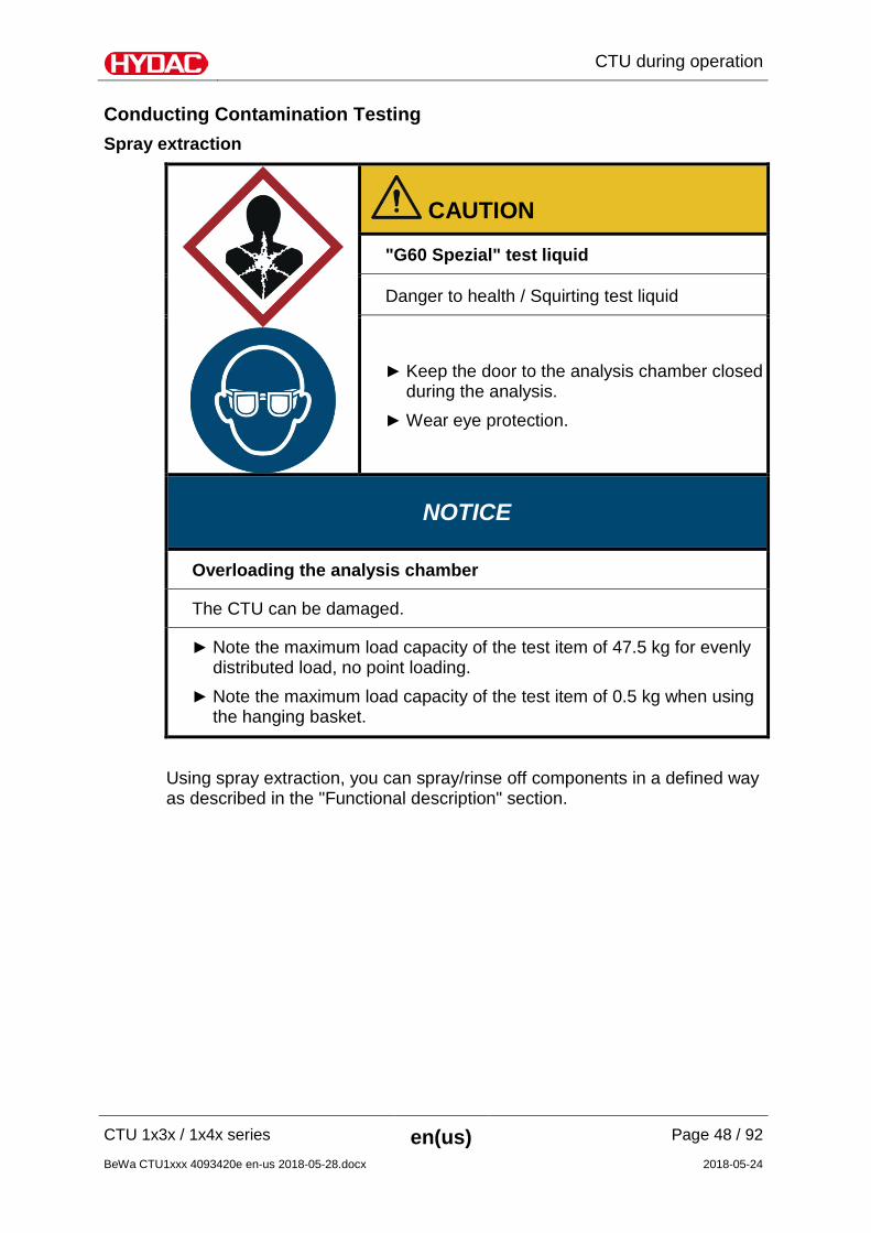
Conducting Contamination Testing Spray extraction
CAUTION
"G60 Spezial" test liquid
Danger to health / Squirting test liquid
Keep the door to the analysis chamber closed during the analysis.
Wear eye protection.
NOTICE
Overloading the analysis chamber
The CTU can be damaged.
Note the maximum load capacity of the test item of 47.5 kg for evenly distributed load, no point loading.
Note the maximum load capacity of the test item of 0.5 kg when using the hanging basket.
Using spray extraction, you can spray/rinse off components in a defined way as described in the "Functional description" section.
CTU during operation
CTU 1x3x / 1x4x series en(us) Page 49 / 92
BeWa CTU1xxx 4093420e en-us 2018-05-28.docx 2018-05-24
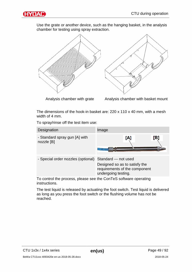
Use the grate or another device, such as the hanging basket, in the analysis chamber for testing using spray extraction.
Analysis chamber with grate Analysis chamber with basket mount
The dimensions of the hook-in basket are: 220 x 110 x 40 mm, with a mesh width of 4 mm. To spray/rinse off the test item use:
Designation Image
- Standard spray gun [A] with nozzle [B]
- Special order nozzles (optional) Standard — not used Designed so as to satisfy the requirements of the component undergoing testing.
To control the process, please see the ConTeS software operating instructions. The test liquid is released by actuating the foot switch. Test liquid is delivered as long as you press the foot switch or the flushing volume has not be reached.
CTU during operation
CTU 1x3x / 1x4x series en(us) Page 50 / 92
BeWa CTU1xxx 4093420e en-us 2018-05-28.docx 2018-05-24
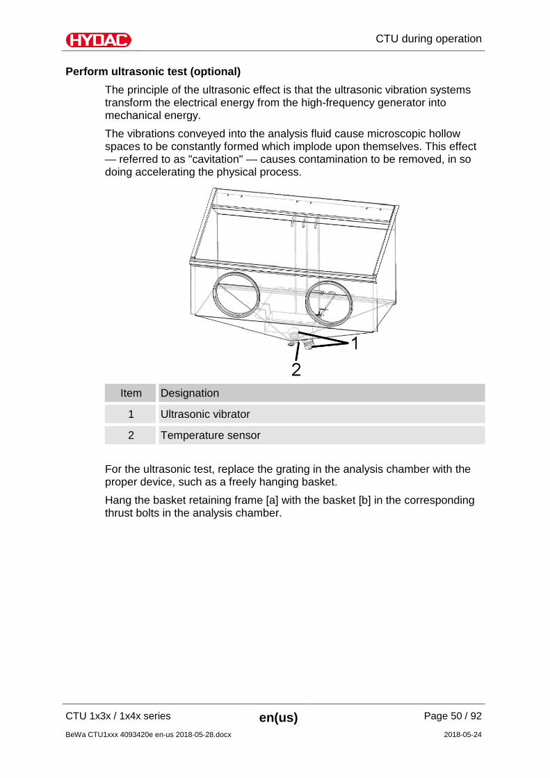
Perform ultrasonic test (optional) The principle of the ultrasonic effect is that the ultrasonic vibration systems transform the electrical energy from the high-frequency generator into mechanical energy. The vibrations conveyed into the analysis fluid cause microscopic hollow spaces to be constantly formed which implode upon themselves. This effect — referred to as "cavitation" — causes contamination to be removed, in so doing accelerating the physical process.
Item Designation
1 Ultrasonic vibrator
2 Temperature sensor For the ultrasonic test, replace the grating in the analysis chamber with the proper device, such as a freely hanging basket. Hang the basket retaining frame [a] with the basket [b] in the corresponding thrust bolts in the analysis chamber.

CTU during operation
CTU 1x3x / 1x4x series en(us) Page 51 / 92
BeWa CTU1xxx 4093420e en-us 2018-05-28.docx 2018-05-24
Analysis chamber with basket mount
NOTICE
Ultrasonic tests without a suitable jig
The CTU will be damaged/destroyed
Do not reduce the fill quantity of the analysis liquid before a test. Never put a test item into the analysis chamber without the
corresponding jig Use the hook-in basket. Note the maximum weight of the test item of
0.5 kg.
The minimum fill quantity of the analysis liquid for ultrasonic testing is given in the software by the defined minimum value of the fill quantity. The ultrasonic bath is subject to continuous temperature monitoring. If a temperature of 34°C is reached during ultrasonic testing, the monitor will switch off the ultrasonic vibrator. Testing will be interrupted while the unit cools down. Close the ball valve on the filter membrane holder during the ultrasonic test.
CTU during operation
CTU 1x3x / 1x4x series en(us) Page 52 / 92
BeWa CTU1xxx 4093420e en-us 2018-05-28.docx 2018-05-24
Automatic reservoir switchover The levels in reservoirs B1 and B2 are continuously monitored during the rinsing of the inner chamber. When the level in reservoir B1 reaches the lower threshold, the system automatically changes between reservoir B1 and reservoir B2 so that when processing continues, the test liquid will be pumped from reservoir B2 to B1. The message "Switching reservoirs - Please wait" is output in the status line of the ConTeS.
The status light additionally blinks red . The supply of test liquid will be stopped. It takes a maximum of 75 seconds to change over the rinsing reservoirs. If rinsing of the inner chamber is complete before the remaining volume has been used, the system will immediately switch containers as soon as the rinsing stops.
If both reservoirs B1 and B2 reach the lower threshold at the same time, the CTU will constantly switch from one to the other. This is possible if the test/analysis liquid is still in the analysis chamber or is in another, external test item.
• Check that the ball valve is in the "Open" position.
• Check the filter membrane, as it is possible that this is so blocked that no more analysis liquid can be sucked away.
• Use the vacuum to suck the test/analysis liquid back into the reservoirs. To accomplish this, use the "Fill CTU" function in the software.
CTU during operation
CTU 1x3x / 1x4x series en(us) Page 53 / 92
BeWa CTU1xxx 4093420e en-us 2018-05-28.docx 2018-05-24
CTU switching off To switch off the CTU, proceed as follows:
1. Exit the operating software of the CTU. You can then get back to the operating system level of the PC.
2. In the operating system START menu, select "Turn Off Computer". Check that the "Shut down" option is selected. If necessary, correct this and confirm by pressing the OK button.
3. The following briefly appears on the screen: "No signal“, followed by the screen going dark.
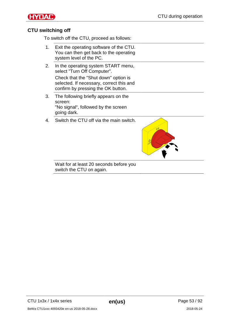
4. Switch the CTU off via the main switch.
Wait for at least 20 seconds before you
switch the CTU on again.
Changing the filter membrane
CTU 1x3x / 1x4x series en(us) Page 54 / 92
BeWa CTU1xxx 4093420e en-us 2018-05-28.docx 2018-05-24
Changing the filter membrane
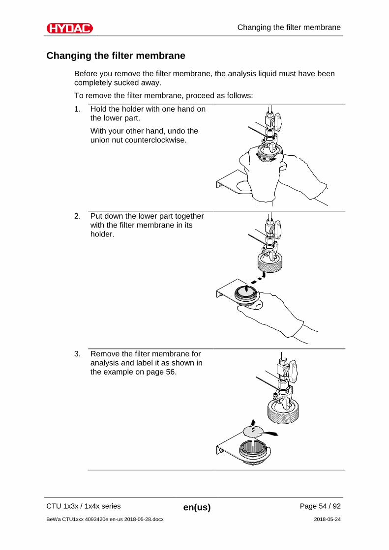
Before you remove the filter membrane, the analysis liquid must have been completely sucked away. To remove the filter membrane, proceed as follows:
1. Hold the holder with one hand on the lower part. With your other hand, undo the union nut counterclockwise.
2. Put down the lower part together
with the filter membrane in its holder.
3. Remove the filter membrane for
analysis and label it as shown in the example on page 56.
Changing the filter membrane
CTU 1x3x / 1x4x series en(us) Page 55 / 92
BeWa CTU1xxx 4093420e en-us 2018-05-28.docx 2018-05-24
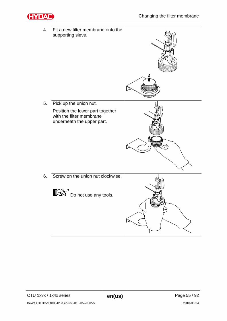
4. Fit a new filter membrane onto the supporting sieve.
5. Pick up the union nut.
Position the lower part together with the filter membrane underneath the upper part.
6. Screw on the union nut clockwise.
Do not use any tools.
Changing the filter membrane
CTU 1x3x / 1x4x series en(us) Page 56 / 92
BeWa CTU1xxx 4093420e en-us 2018-05-28.docx 2018-05-24
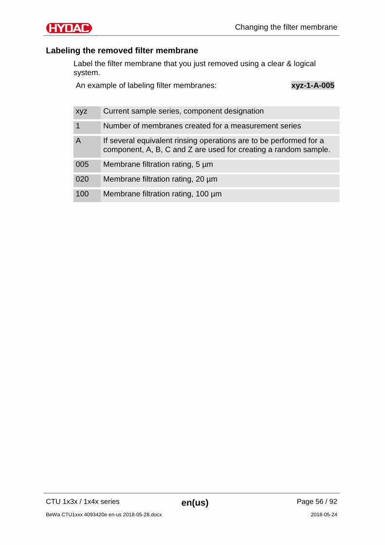
Labeling the removed filter membrane Label the filter membrane that you just removed using a clear & logical system. An example of labeling filter membranes: xyz-1-A-005
xyz Current sample series, component designation
1 Number of membranes created for a measurement series
A If several equivalent rinsing operations are to be performed for a component, A, B, C and Z are used for creating a random sample.
005 Membrane filtration rating, 5 µm
020 Membrane filtration rating, 20 µm
100 Membrane filtration rating, 100 µm
Performing inspection / maintenance
CTU 1x3x / 1x4x series en(us) Page 57 / 92
BeWa CTU1xxx 4093420e en-us 2018-05-28.docx 2018-05-24
Performing inspection / maintenance
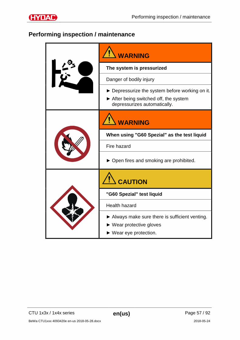
WARNING
The system is pressurized
Danger of bodily injury
Depressurize the system before working on it. After being switched off, the system
depressurizes automatically.
WARNING
When using "G60 Spezial" as the test liquid
Fire hazard
Open fires and smoking are prohibited.
CAUTION
"G60 Spezial" test liquid
Health hazard
Always make sure there is sufficient venting. Wear protective gloves Wear eye protection.
Performing inspection / maintenance
CTU 1x3x / 1x4x series en(us) Page 58 / 92
BeWa CTU1xxx 4093420e en-us 2018-05-28.docx 2018-05-24
User information for the "products under pressure" The reservoirs of the CTU are simply pressurized products and are thus excluded in accordance to Article 1, Paragraph f i); 2014/68/EU of the Pressure Equipment Directive. As such, the CTU system does not need to be monitored as per the Industrial Safety Regulation. The validity of the owner's obligation to "normal" work equipment provision is not affected by this in accordance with the Labor Protection Law.
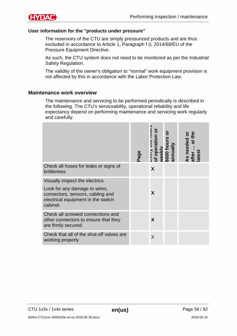
Maintenance work overview The maintenance and servicing to be performed periodically is described in the following. The CTU’s serviceability, operational reliability and life expectancy depend on performing maintenance and servicing work regularly and carefully.
Page
Ever
y 10
0 ho
urs
of o
pera
tion
or
wee
kly
6000
hou
rs o
r an
nual
ly
As
need
ed o
r af
ter …
at t
he
late
st
Check all hoses for leaks or signs of brittleness X
Visually inspect the electrics. Look for any damage to wires, connectors, sensors, cabling and electrical equipment in the switch cabinet.
X
Check all screwed connections and other connectors to ensure that they are firmly secured.
X
Check that all of the shut-off valves are working properly X

Performing inspection / maintenance
CTU 1x3x / 1x4x series en(us) Page 59 / 92
BeWa CTU1xxx 4093420e en-us 2018-05-28.docx 2018-05-24
Page
Ever
y 10
0 ho
urs
of o
pera
tion
or
wee
kly
6000
hou
rs o
r an
nual
ly
As
need
ed o
r af
ter …
at t
he
late
st
Maintenance intervals for CTU 1xx0 with A III cleaner as the test liquid
Checking / Replacing hoses 60 2 years
Changing the filter element 61 1 year
Calibrating the flow rate meter 63 X
Calibrate the temperature sensor (ultrasound option only) 64 X
Clean the analysis chamber 65 X
Cleaning the diffuser for the filter membrane holder 65 X
Change the test liquid 67 1 month
Checking the gloves 75 6 months
Maintenance intervals for CTU 1xx1 with A III cleaner as the test liquid
Checking / Replacing hoses 60 2 years
Changing the filter element 61 1 year
Calibrating the flow rate meter 63 X
Calibrate the temperature sensor (ultrasound option only) 64 X
Clean the analysis chamber 65 X
Cleaning the diffuser for the filter membrane holder 65 X
Change the test liquid 67 X 1 month
Performing inspection / maintenance
CTU 1x3x / 1x4x series en(us) Page 60 / 92
BeWa CTU1xxx 4093420e en-us 2018-05-28.docx 2018-05-24
Page
Ever
y 10
0 ho
urs
of o
pera
tion
or
wee
kly
6000
hou
rs o
r an
nual
ly
As
need
ed o
r af
ter …
at t
he
late
st
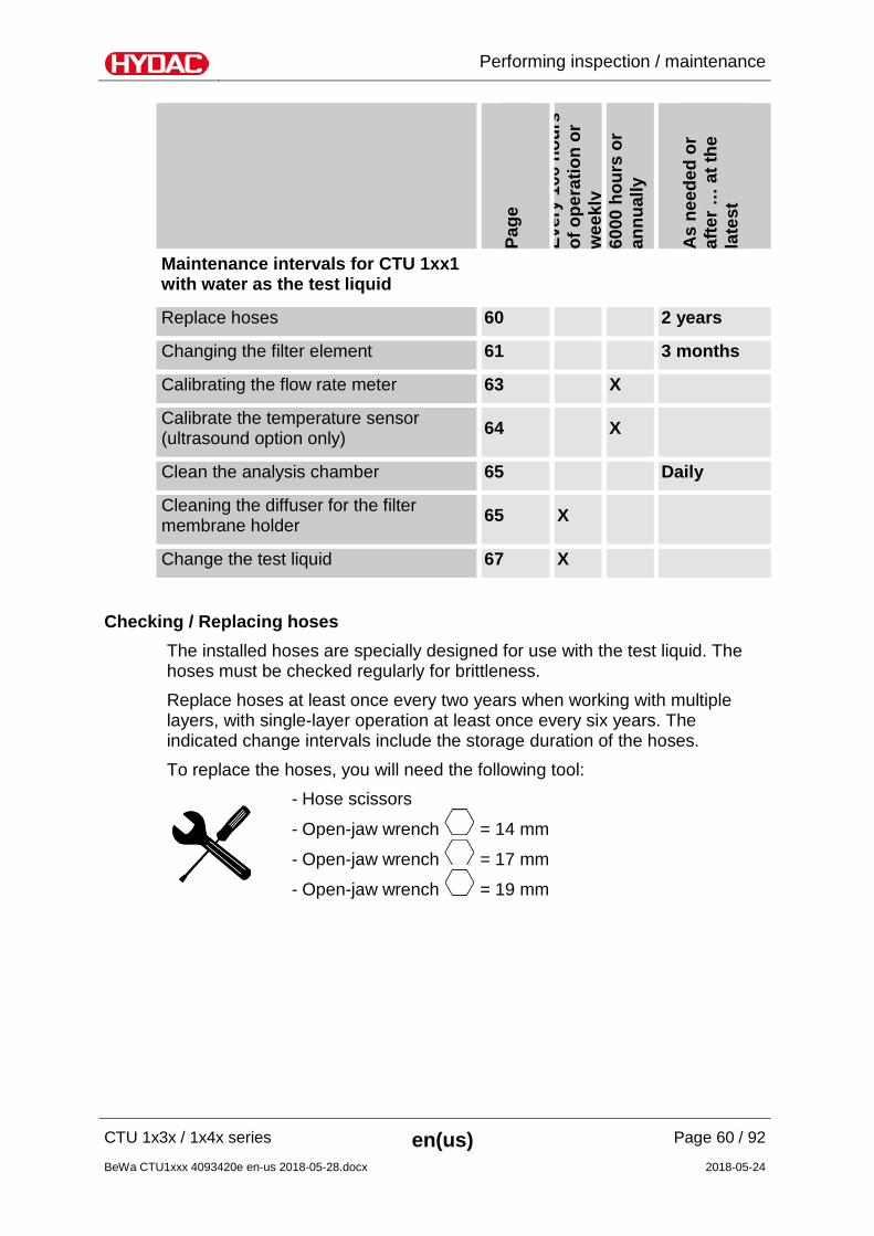
Maintenance intervals for CTU 1xx1 with water as the test liquid
Replace hoses 60 2 years
Changing the filter element 61 3 months
Calibrating the flow rate meter 63 X
Calibrate the temperature sensor (ultrasound option only) 64 X
Clean the analysis chamber 65 Daily
Cleaning the diffuser for the filter membrane holder 65 X
Change the test liquid 67 X
Checking / Replacing hoses
The installed hoses are specially designed for use with the test liquid. The hoses must be checked regularly for brittleness. Replace hoses at least once every two years when working with multiple layers, with single-layer operation at least once every six years. The indicated change intervals include the storage duration of the hoses. To replace the hoses, you will need the following tool:
- Hose scissors
- Open-jaw wrench = 14 mm
- Open-jaw wrench = 17 mm
- Open-jaw wrench = 19 mm
Performing inspection / maintenance
CTU 1x3x / 1x4x series en(us) Page 61 / 92
BeWa CTU1xxx 4093420e en-us 2018-05-28.docx 2018-05-24
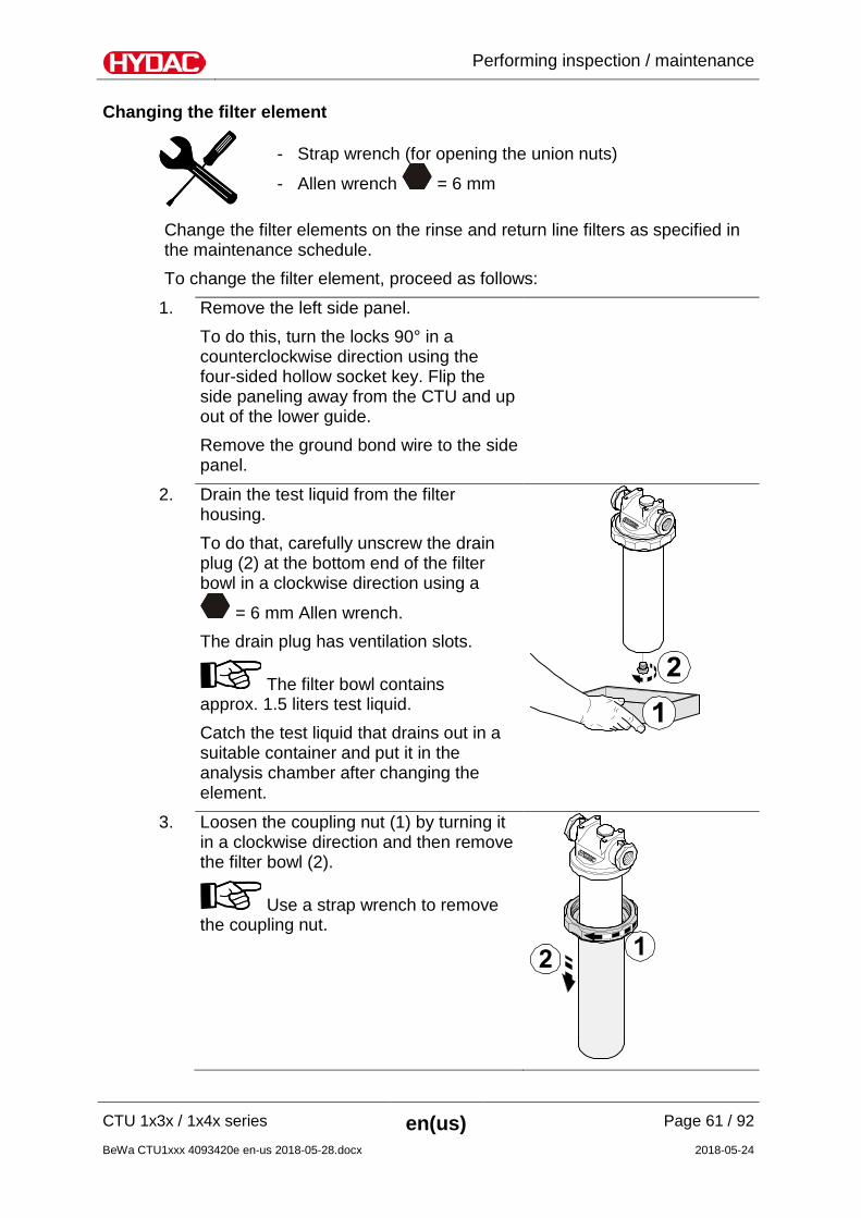
Changing the filter element
- Strap wrench (for opening the union nuts)
- Allen wrench = 6 mm
Change the filter elements on the rinse and return line filters as specified in the maintenance schedule. To change the filter element, proceed as follows:
1. Remove the left side panel. To do this, turn the locks 90° in a counterclockwise direction using the four-sided hollow socket key. Flip the side paneling away from the CTU and up out of the lower guide. Remove the ground bond wire to the side panel.
2. Drain the test liquid from the filter housing. To do that, carefully unscrew the drain plug (2) at the bottom end of the filter bowl in a clockwise direction using a
= 6 mm Allen wrench. The drain plug has ventilation slots.
The filter bowl contains approx. 1.5 liters test liquid. Catch the test liquid that drains out in a suitable container and put it in the analysis chamber after changing the element.
3. Loosen the coupling nut (1) by turning it in a clockwise direction and then remove the filter bowl (2).
Use a strap wrench to remove the coupling nut.
Performing inspection / maintenance
CTU 1x3x / 1x4x series en(us) Page 62 / 92
BeWa CTU1xxx 4093420e en-us 2018-05-28.docx 2018-05-24
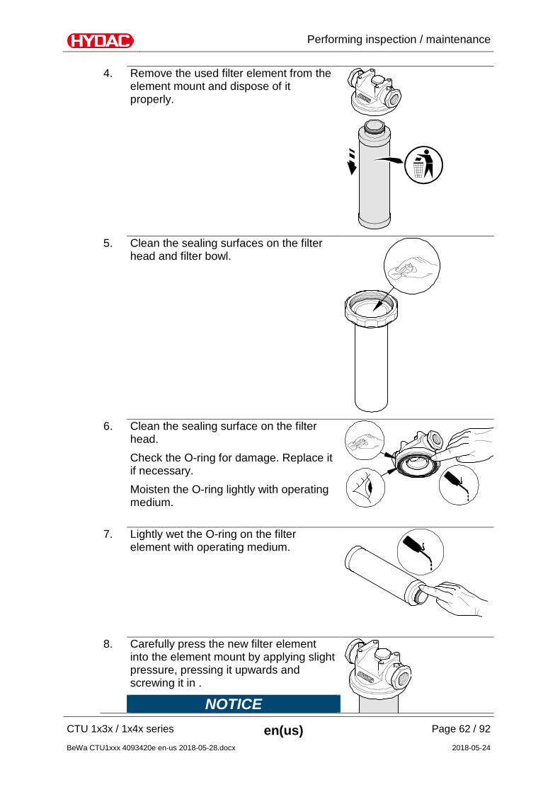
4. Remove the used filter element from the element mount and dispose of it properly.
5. Clean the sealing surfaces on the filter
head and filter bowl.
6. Clean the sealing surface on the filter
head. Check the O-ring for damage. Replace it if necessary. Moisten the O-ring lightly with operating medium.
7. Lightly wet the O-ring on the filter element with operating medium.
8. Carefully press the new filter element into the element mount by applying slight pressure, pressing it upwards and screwing it in .
NOTICE
Performing inspection / maintenance
CTU 1x3x / 1x4x series en(us) Page 63 / 92
BeWa CTU1xxx 4093420e en-us 2018-05-28.docx 2018-05-24
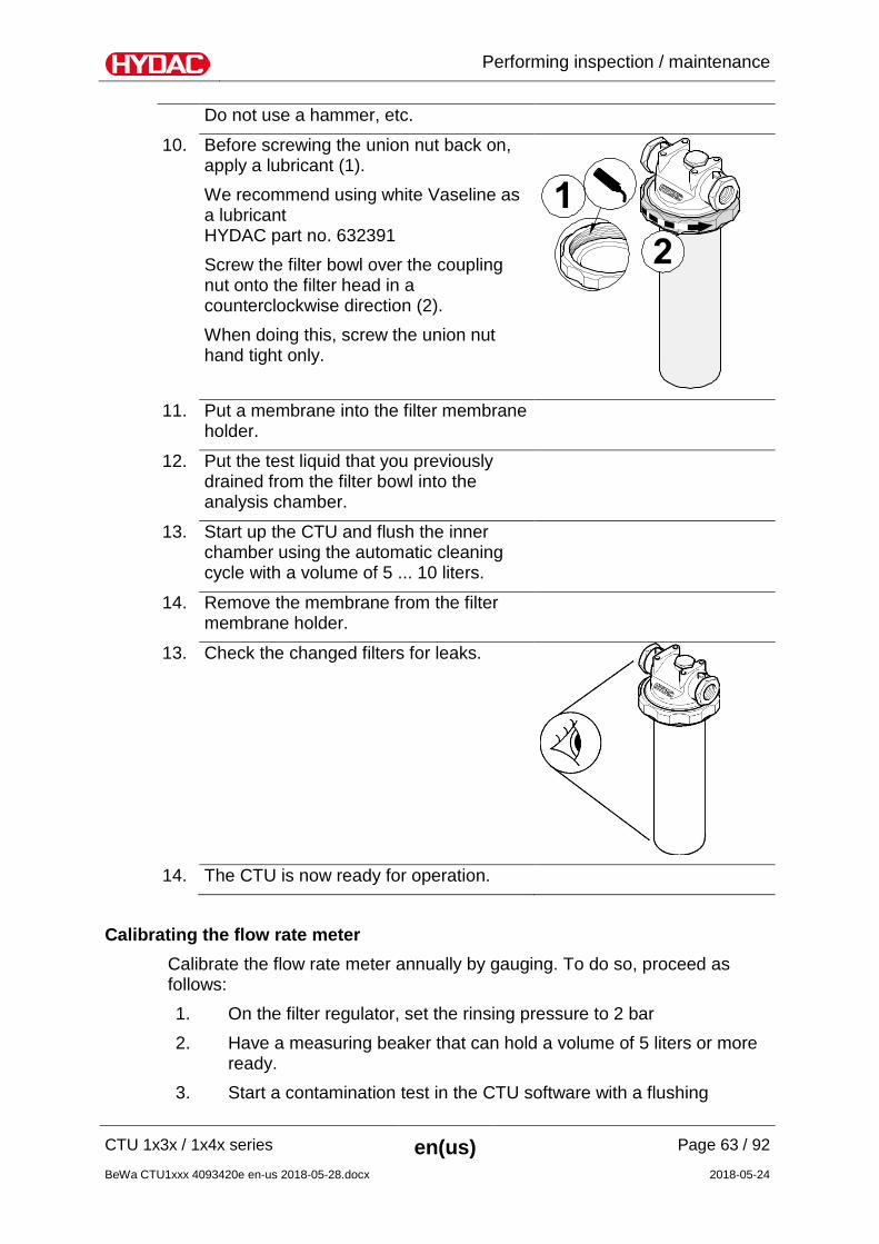
Do not use a hammer, etc.
10. Before screwing the union nut back on, apply a lubricant (1). We recommend using white Vaseline as a lubricant HYDAC part no. 632391 Screw the filter bowl over the coupling nut onto the filter head in a counterclockwise direction (2). When doing this, screw the union nut hand tight only.
11. Put a membrane into the filter membrane
holder.
12. Put the test liquid that you previously drained from the filter bowl into the analysis chamber.
13. Start up the CTU and flush the inner chamber using the automatic cleaning cycle with a volume of 5 ... 10 liters.
14. Remove the membrane from the filter membrane holder.
13. Check the changed filters for leaks.
14. The CTU is now ready for operation.
Calibrating the flow rate meter
Calibrate the flow rate meter annually by gauging. To do so, proceed as follows: 1. On the filter regulator, set the rinsing pressure to 2 bar 2. Have a measuring beaker that can hold a volume of 5 liters or more
ready. 3. Start a contamination test in the CTU software with a flushing

Performing inspection / maintenance
CTU 1x3x / 1x4x series en(us) Page 64 / 92
BeWa CTU1xxx 4093420e en-us 2018-05-28.docx 2018-05-24
volume of 5 liters. 4. Fill the measuring beaker using the spray gun (nozzle) of the CTU
by operating the foot switch until the set volume has been completely discharged.
5. Read the volume on the measuring beaker. A deviation of +/- 5% (4.75 - 5.25 liters) is within the tolerance. The flow rate meter will need to be recalibrated if the deviation is greater. Contact the HYDAC Service Department.
6. The calibration by gauging is completed.
Calibrating the temperature sensor (ultrasound option only) Calibrate the temperature feeler for the ultrasound bath annually. Contact the HYDAC service department for this purpose.
Performing inspection / maintenance
CTU 1x3x / 1x4x series en(us) Page 65 / 92
BeWa CTU1xxx 4093420e en-us 2018-05-28.docx 2018-05-24
Cleaning the analysis chamber The cleaning cycles of the analysis chamber are dependent on the test liquid used. Used test liquid Daily Weekly
Water containing surfactants X
AIII cleaners or similar, such as G 60 Spezial X For cleaning, we recommend a moist, clean, commercial microfiber cloth. Finish cleaning with a long rinsing of the inner chamber.
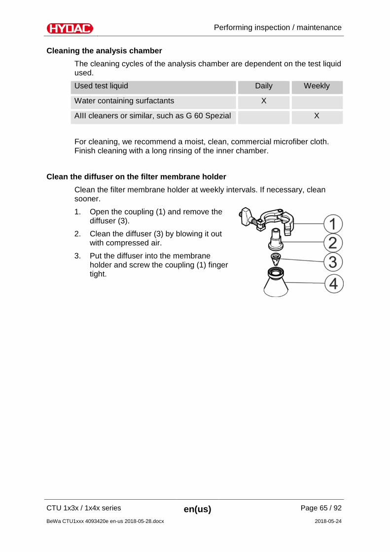
Clean the diffuser on the filter membrane holder Clean the filter membrane holder at weekly intervals. If necessary, clean sooner. 1. Open the coupling (1) and remove the
diffuser (3).
2. Clean the diffuser (3) by blowing it out with compressed air.
3. Put the diffuser into the membrane holder and screw the coupling (1) finger tight.
Performing inspection / maintenance
CTU 1x3x / 1x4x series en(us) Page 66 / 92
BeWa CTU1xxx 4093420e en-us 2018-05-28.docx 2018-05-24
Cleaning the door Clean the see-through door regularly.
CAUTION
Electrostatic charging
Danger of uncontrolled electrical discharge
Always clean the door with a moist, lint free cloth.
Do not use a dry cloth.
Maintaining statically charged door
In certain circumstances, the door can become statically charged. One possible cause of this is when two non-conducting substances, e.g., CTU gloves (neoprene), see-through door (Makrolon), cleaning cloths (cellulose or cotton), are rubbed against one another, thus causing static charge to build up. Discharging may be slowed down by the ambient conditions, such as dry air and low external temperatures. One visual feature which comes about when using the "G 60 Spezial" test liquid is that a film that looks like a pasty mass forms on the inside of the door. The build-up of static charge counteracts the low surface tension of the hydrocarbon mixture. If the same liquid is transferred from a statically charged surface to a surface with no charge, the liquid will be distributed in the usual manner. The following points are useful: - Rinse down the inside of the door with test liquid. - Adjust the humidity in the surroundings. - Always clean the disk of the CTU with damp cloths. - If there is a lot of static, use a commercial anti-static product.
Performing inspection / maintenance
CTU 1x3x / 1x4x series en(us) Page 67 / 92
BeWa CTU1xxx 4093420e en-us 2018-05-28.docx 2018-05-24
Change the test liquid As a result, the change intervals for the test liquid are difficult to establish. Determine the replacement intervals for each application on an individual basis. Check the test liquid with regard to the following characteristics: - Odor. - Appearance
(greases, oils, preservatives, water have the effect of clouding the test liquid or giving it a yellow tint)
- See page 37 for achievable negative control values.
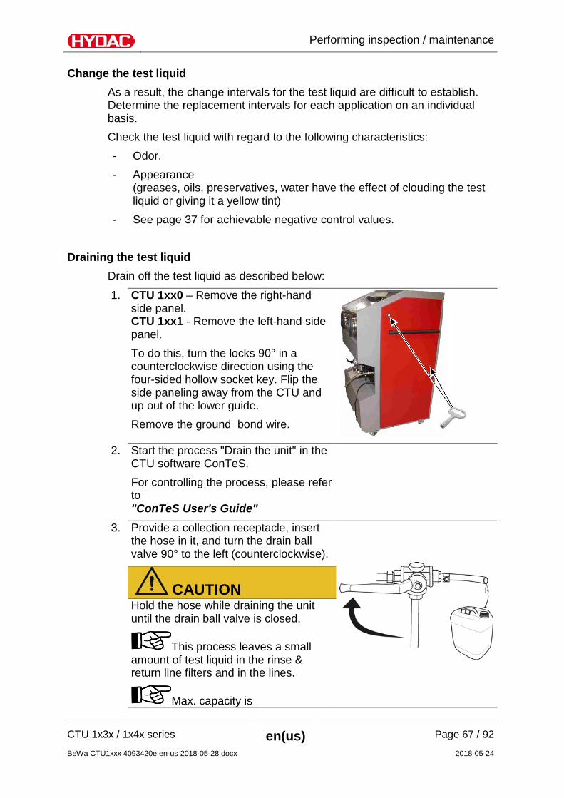
Draining the test liquid Drain off the test liquid as described below:
1. CTU 1xx0 – Remove the right-hand side panel. CTU 1xx1 - Remove the left-hand side panel. To do this, turn the locks 90° in a counterclockwise direction using the four-sided hollow socket key. Flip the side paneling away from the CTU and up out of the lower guide. Remove the ground bond wire.
2. Start the process "Drain the unit" in the
CTU software ConTeS. For controlling the process, please refer to "ConTeS User's Guide"
3. Provide a collection receptacle, insert the hose in it, and turn the drain ball valve 90° to the left (counterclockwise).
CAUTION Hold the hose while draining the unit until the drain ball valve is closed.
This process leaves a small amount of test liquid in the rinse & return line filters and in the lines.
Max. capacity is
Performing inspection / maintenance
CTU 1x3x / 1x4x series en(us) Page 68 / 92
BeWa CTU1xxx 4093420e en-us 2018-05-28.docx 2018-05-24
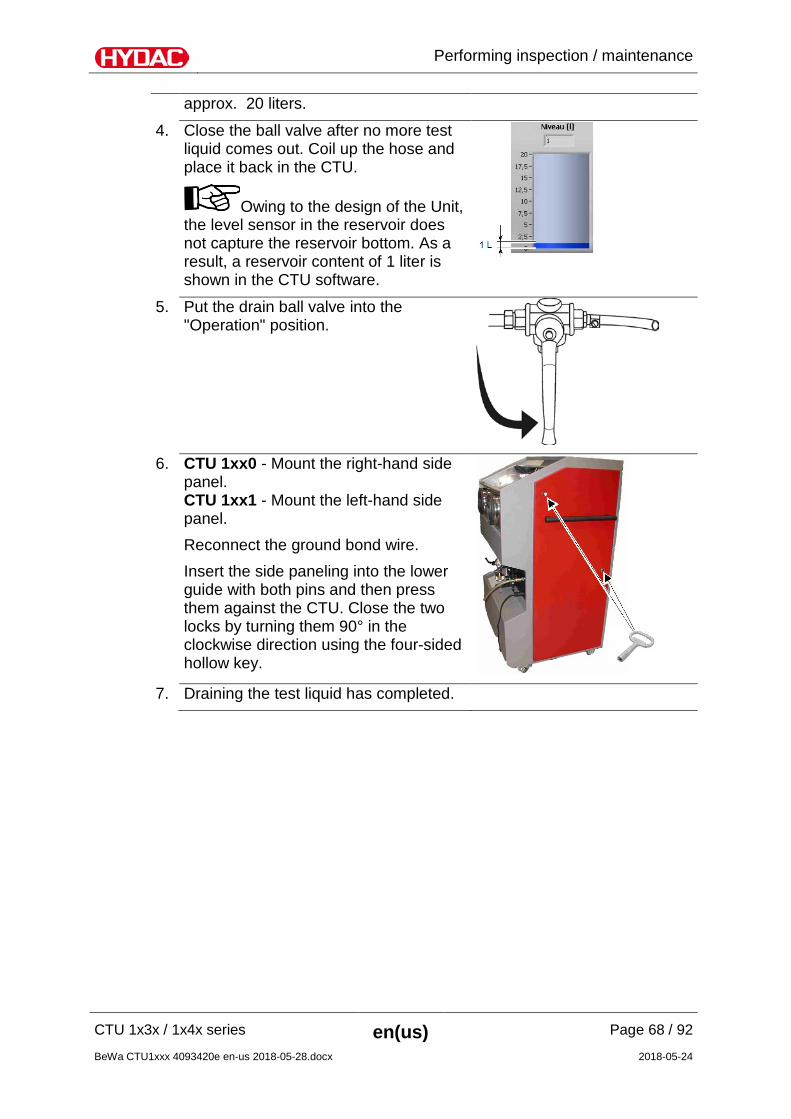
approx. 20 liters.
4. Close the ball valve after no more test liquid comes out. Coil up the hose and place it back in the CTU.
Owing to the design of the Unit, the level sensor in the reservoir does not capture the reservoir bottom. As a result, a reservoir content of 1 liter is shown in the CTU software.
5. Put the drain ball valve into the "Operation" position.
6. CTU 1xx0 - Mount the right-hand side
panel. CTU 1xx1 - Mount the left-hand side panel. Reconnect the ground bond wire. Insert the side paneling into the lower guide with both pins and then press them against the CTU. Close the two locks by turning them 90° in the clockwise direction using the four-sided hollow key.
7. Draining the test liquid has completed.
Performing inspection / maintenance
CTU 1x3x / 1x4x series en(us) Page 69 / 92
BeWa CTU1xxx 4093420e en-us 2018-05-28.docx 2018-05-24
Adding / Filling test liquid To add test liquid, follow all instructions and the following procedure.
NOTICE
Overfilling the reservoir
The CTU does not work.
Add only the required indicated fill quantity for the test liquid. If the tanks are overfilled, drain the test liquid as described on page
67.
Before adding liquid, calculate the maximum fill quantity according to the following formula:
Fill quantity during initial filling 20 liter
Fill quantity when topping off 19 liters Content (reservoir B1) – Content (reservoir B2)
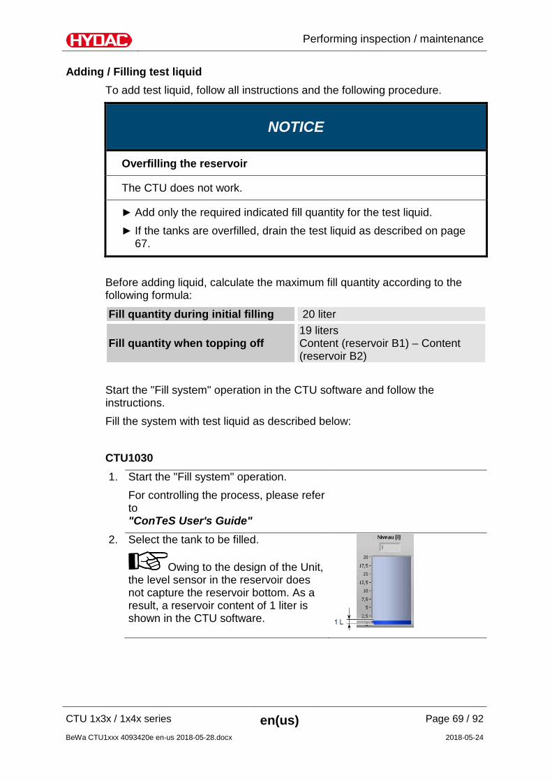
Start the "Fill system" operation in the CTU software and follow the instructions. Fill the system with test liquid as described below: CTU1030 1. Start the "Fill system" operation.
For controlling the process, please refer to "ConTeS User's Guide"
2. Select the tank to be filled.
Owing to the design of the Unit, the level sensor in the reservoir does not capture the reservoir bottom. As a result, a reservoir content of 1 liter is shown in the CTU software.
Performing inspection / maintenance
CTU 1x3x / 1x4x series en(us) Page 70 / 92
BeWa CTU1xxx 4093420e en-us 2018-05-28.docx 2018-05-24
3. Pour the previously determined and measured test liquid into the analysis chamber of the CTU.
NOTICE Maximum capacity is approx. 20 liters.
4. Then start the suctioning of the test liquid in the CTU software. The added test liquid is suctioned into the pre-selected reservoir B1 or B2.
5. Wait until the test liquid is completely suctioned out.
6. If you have added more than the displayed volume in the analysis chamber, a residual quantity remains in the analysis chamber.
• Close the ball valve above the membrane holder.
• Open the membrane holder and place a suitable container for catching the test liquid underneath it.
• Open the ball valve above the filter membrane holder and drain the residual amount from the analysis chamber.
7. The filling of the system is completed.
Performing inspection / maintenance
CTU 1x3x / 1x4x series en(us) Page 71 / 92
BeWa CTU1xxx 4093420e en-us 2018-05-28.docx 2018-05-24
CTU1040 1. Prepare the container with test liquid.
2. • Detach the plug with breather filter from the ball valve.
• Attach the suction hose to the ball valve.
• Ball valve in "Bleeding" position.
3. In ConTeS, start the "Fill system" menu.
4. System is being filled. Overfilling is not possible as the software ends the filling process automatically.
5. • Ball valve in "Operation" position. • Detach the suction hose from the
ball valve. • Attach the plug with breather filter to
the ball valve.
6. The filling of the system is completed.
Performing inspection / maintenance
CTU 1x3x / 1x4x series en(us) Page 72 / 92
BeWa CTU1xxx 4093420e en-us 2018-05-28.docx 2018-05-24
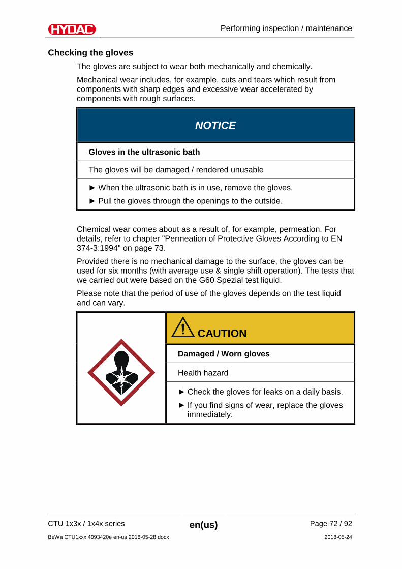
Checking the gloves The gloves are subject to wear both mechanically and chemically. Mechanical wear includes, for example, cuts and tears which result from components with sharp edges and excessive wear accelerated by components with rough surfaces.
NOTICE
Gloves in the ultrasonic bath
The gloves will be damaged / rendered unusable
When the ultrasonic bath is in use, remove the gloves. Pull the gloves through the openings to the outside.
Chemical wear comes about as a result of, for example, permeation. For details, refer to chapter "Permeation of Protective Gloves According to EN 374-3:1994" on page 73. Provided there is no mechanical damage to the surface, the gloves can be used for six months (with average use & single shift operation). The tests that we carried out were based on the G60 Spezial test liquid. Please note that the period of use of the gloves depends on the test liquid and can vary.
CAUTION
Damaged / Worn gloves
Health hazard
Check the gloves for leaks on a daily basis. If you find signs of wear, replace the gloves
immediately.
Performing inspection / maintenance
CTU 1x3x / 1x4x series en(us) Page 73 / 92
BeWa CTU1xxx 4093420e en-us 2018-05-28.docx 2018-05-24
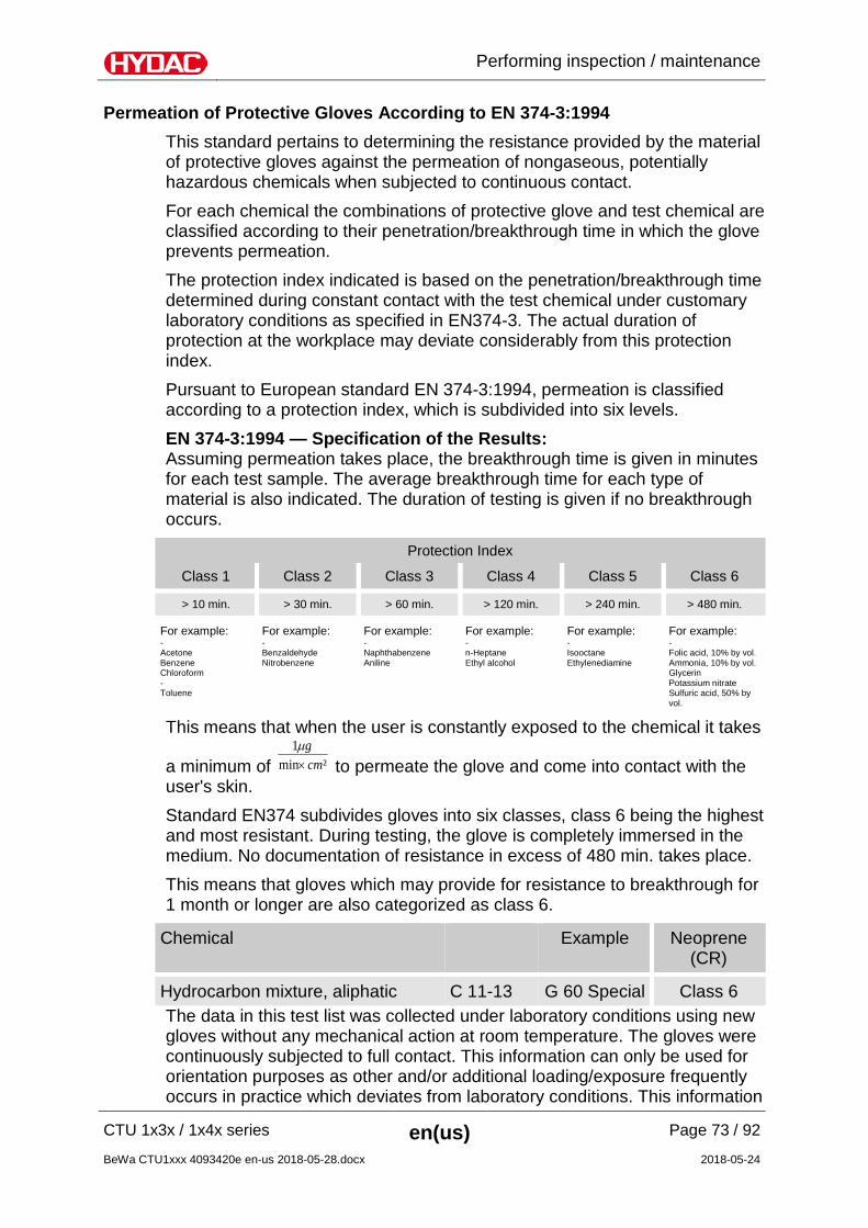
Permeation of Protective Gloves According to EN 374-3:1994 This standard pertains to determining the resistance provided by the material of protective gloves against the permeation of nongaseous, potentially hazardous chemicals when subjected to continuous contact. For each chemical the combinations of protective glove and test chemical are classified according to their penetration/breakthrough time in which the glove prevents permeation. The protection index indicated is based on the penetration/breakthrough time determined during constant contact with the test chemical under customary laboratory conditions as specified in EN374-3. The actual duration of protection at the workplace may deviate considerably from this protection index. Pursuant to European standard EN 374-3:1994, permeation is classified according to a protection index, which is subdivided into six levels. EN 374-3:1994 — Specification of the Results: Assuming permeation takes place, the breakthrough time is given in minutes for each test sample. The average breakthrough time for each type of material is also indicated. The duration of testing is given if no breakthrough occurs.
Protection Index
Class 1 Class 2 Class 3 Class 4 Class 5 Class 6
> 10 min. > 30 min. > 60 min. > 120 min. > 240 min. > 480 min.
For example: For example: For example: For example: For example: For example: - Acetone Benzene Chloroform - Toluene
- Benzaldehyde Nitrobenzene
- Naphthabenzene Aniline
- n-Heptane Ethyl alcohol
- Isooctane Ethylenediamine
- Folic acid, 10% by vol. Ammonia, 10% by vol. Glycerin Potassium nitrate Sulfuric acid, 50% by vol.
This means that when the user is constantly exposed to the chemical it takes
a minimum of ²min1
cmg×m
to permeate the glove and come into contact with the user's skin. Standard EN374 subdivides gloves into six classes, class 6 being the highest and most resistant. During testing, the glove is completely immersed in the medium. No documentation of resistance in excess of 480 min. takes place. This means that gloves which may provide for resistance to breakthrough for 1 month or longer are also categorized as class 6.
Chemical Example Neoprene (CR)
Hydrocarbon mixture, aliphatic C 11-13 G 60 Special Class 6 The data in this test list was collected under laboratory conditions using new gloves without any mechanical action at room temperature. The gloves were continuously subjected to full contact. This information can only be used for orientation purposes as other and/or additional loading/exposure frequently occurs in practice which deviates from laboratory conditions. This information
Performing inspection / maintenance
CTU 1x3x / 1x4x series en(us) Page 74 / 92
BeWa CTU1xxx 4093420e en-us 2018-05-28.docx 2018-05-24
is not designed as a substitute for suitability testing conducted by the end user. Consequently, HYDAC assumes no liability or responsibility for the information provided in this list.
Performing inspection / maintenance
CTU 1x3x / 1x4x series en(us) Page 75 / 92
BeWa CTU1xxx 4093420e en-us 2018-05-28.docx 2018-05-24
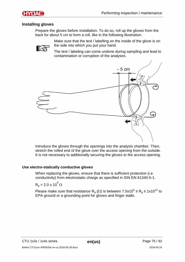
Installing gloves Prepare the gloves before installation. To do so, roll up the gloves from the back for about 5 cm to form a roll, like in the following illustration.
Make sure that the text / labelling on the inside of the glove is on the side into which you put your hand. The text / labeling can come undone during sampling and lead to contamination or corruption of the analyses.
Introduce the gloves through the openings into the analysis chamber. Then, stretch the rolled end of the glove over the access opening from the outside. It is not necessary to additionally securing the gloves to the access opening.
Use electro-statically conductive gloves When replacing the gloves, ensure that there is sufficient protection (i.e. conductivity) from electrostatic charge as specified in IDN EN 61340-5-1.
Rg = 2.0 x 10⁸ Ω
Please make sure that resistance Rg (Ω) is between 7.5x10⁵ ≤ Rg ≤ 1x10¹² to EPA ground or a grounding point for gloves and finger stalls.
Spare parts list
CTU 1x3x / 1x4x series en(us) Page 76 / 92
BeWa CTU1xxx 4093420e en-us 2018-05-28.docx 2018-05-24
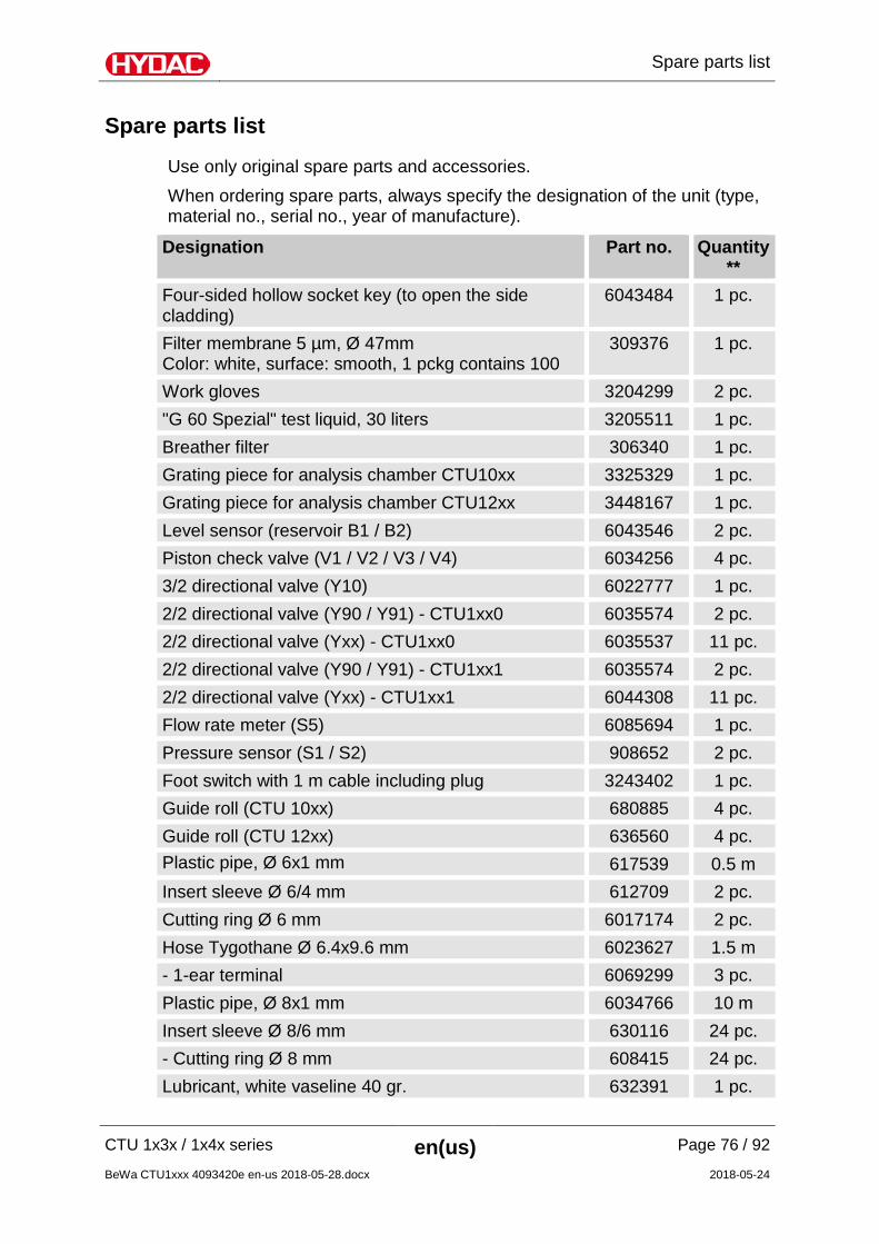
Spare parts list
Use only original spare parts and accessories. When ordering spare parts, always specify the designation of the unit (type, material no., serial no., year of manufacture).
Designation Part no. Quantity**
Four-sided hollow socket key (to open the side cladding)
6043484 1 pc.
Filter membrane 5 µm, Ø 47mm Color: white, surface: smooth, 1 pckg contains 100
309376 1 pc.
Work gloves 3204299 2 pc. "G 60 Spezial" test liquid, 30 liters 3205511 1 pc. Breather filter 306340 1 pc. Grating piece for analysis chamber CTU10xx 3325329 1 pc. Grating piece for analysis chamber CTU12xx 3448167 1 pc. Level sensor (reservoir B1 / B2) 6043546 2 pc. Piston check valve (V1 / V2 / V3 / V4) 6034256 4 pc. 3/2 directional valve (Y10) 6022777 1 pc. 2/2 directional valve (Y90 / Y91) - CTU1xx0 6035574 2 pc. 2/2 directional valve (Yxx) - CTU1xx0 6035537 11 pc. 2/2 directional valve (Y90 / Y91) - CTU1xx1 6035574 2 pc. 2/2 directional valve (Yxx) - CTU1xx1 6044308 11 pc. Flow rate meter (S5) 6085694 1 pc. Pressure sensor (S1 / S2) 908652 2 pc. Foot switch with 1 m cable including plug 3243402 1 pc. Guide roll (CTU 10xx) 680885 4 pc. Guide roll (CTU 12xx) 636560 4 pc. Plastic pipe, Ø 6x1 mm 617539 0.5 m Insert sleeve Ø 6/4 mm 612709 2 pc. Cutting ring Ø 6 mm 6017174 2 pc. Hose Tygothane Ø 6.4x9.6 mm 6023627 1.5 m - 1-ear terminal 6069299 3 pc. Plastic pipe, Ø 8x1 mm 6034766 10 m Insert sleeve Ø 8/6 mm 630116 24 pc. - Cutting ring Ø 8 mm 608415 24 pc. Lubricant, white vaseline 40 gr. 632391 1 pc.
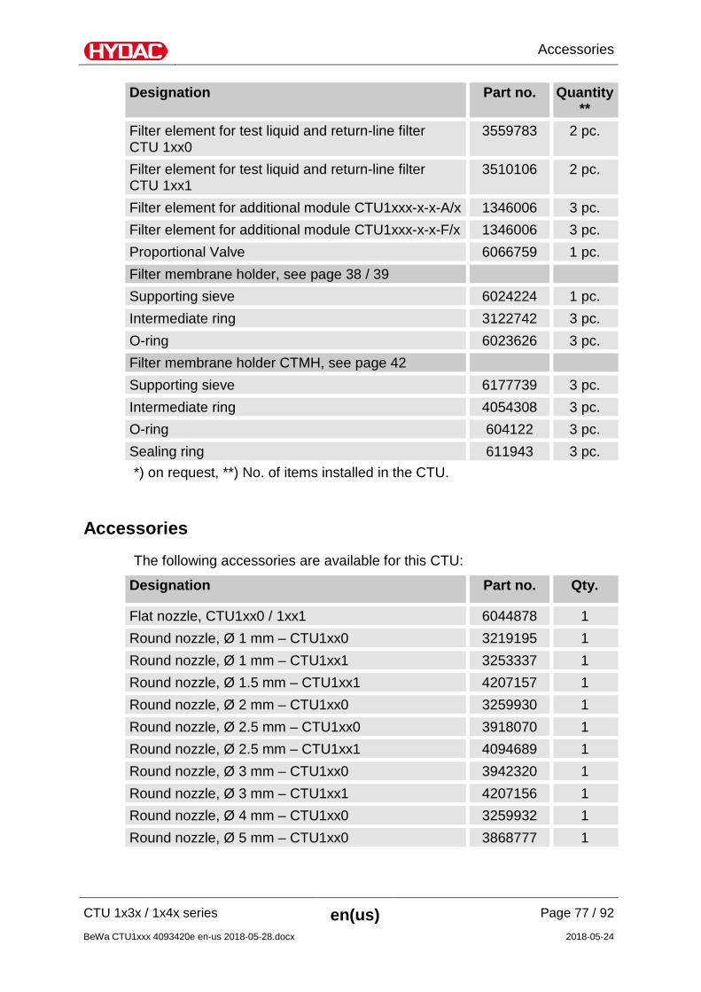
Accessories
CTU 1x3x / 1x4x series en(us) Page 77 / 92
BeWa CTU1xxx 4093420e en-us 2018-05-28.docx 2018-05-24
Designation Part no. Quantity**
Filter element for test liquid and return-line filter CTU 1xx0
3559783 2 pc.
Filter element for test liquid and return-line filter CTU 1xx1
3510106 2 pc.
Filter element for additional module CTU1xxx-x-x-A/x 1346006 3 pc. Filter element for additional module CTU1xxx-x-x-F/x 1346006 3 pc. Proportional Valve 6066759 1 pc. Filter membrane holder, see page 38 / 39 Supporting sieve 6024224 1 pc. Intermediate ring 3122742 3 pc. O-ring 6023626 3 pc. Filter membrane holder CTMH, see page 42 Supporting sieve 6177739 3 pc. Intermediate ring 4054308 3 pc. O-ring 604122 3 pc. Sealing ring 611943 3 pc. *) on request, **) No. of items installed in the CTU.
Accessories
The following accessories are available for this CTU:
Designation Part no. Qty.
Flat nozzle, CTU1xx0 / 1xx1 6044878 1 Round nozzle, Ø 1 mm – CTU1xx0 3219195 1 Round nozzle, Ø 1 mm – CTU1xx1 3253337 1 Round nozzle, Ø 1.5 mm – CTU1xx1 4207157 1 Round nozzle, Ø 2 mm – CTU1xx0 3259930 1 Round nozzle, Ø 2.5 mm – CTU1xx0 3918070 1 Round nozzle, Ø 2.5 mm – CTU1xx1 4094689 1 Round nozzle, Ø 3 mm – CTU1xx0 3942320 1 Round nozzle, Ø 3 mm – CTU1xx1 4207156 1 Round nozzle, Ø 4 mm – CTU1xx0 3259932 1 Round nozzle, Ø 5 mm – CTU1xx0 3868777 1
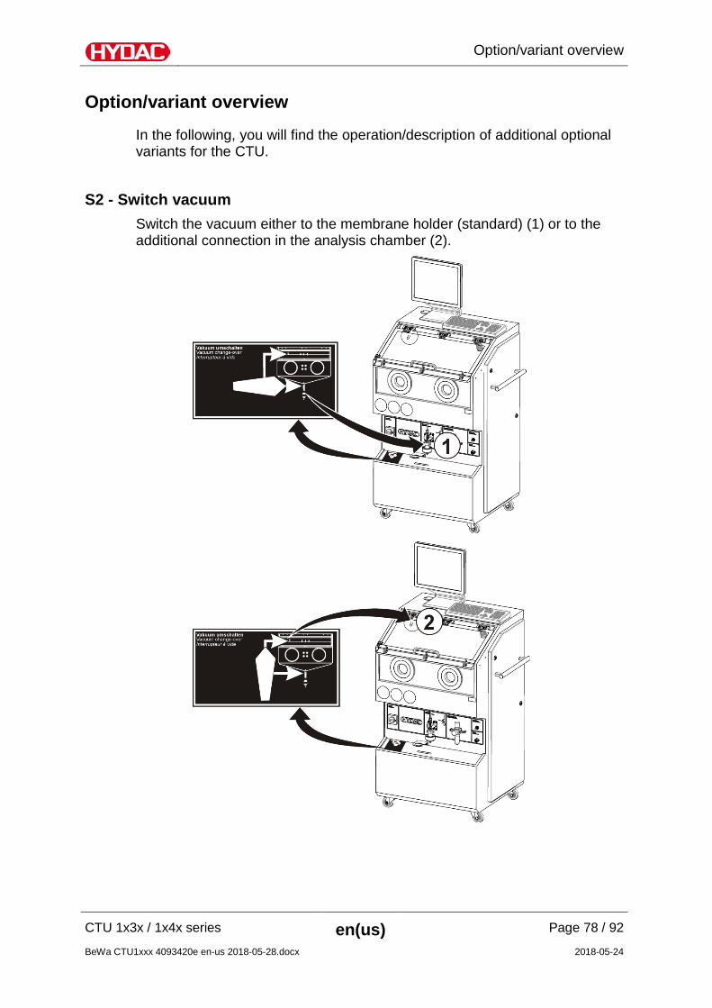
Option/variant overview
CTU 1x3x / 1x4x series en(us) Page 78 / 92
BeWa CTU1xxx 4093420e en-us 2018-05-28.docx 2018-05-24
Option/variant overview
In the following, you will find the operation/description of additional optional variants for the CTU.
S2 - Switch vacuum Switch the vacuum either to the membrane holder (standard) (1) or to the additional connection in the analysis chamber (2).
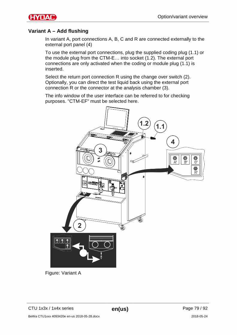
Option/variant overview
CTU 1x3x / 1x4x series en(us) Page 79 / 92
BeWa CTU1xxx 4093420e en-us 2018-05-28.docx 2018-05-24
Variant A – Add flushing In variant A, port connections A, B, C and R are connected externally to the external port panel (4) To use the external port connections, plug the supplied coding plug (1.1) or the module plug from the CTM-E… into socket (1.2). The external port connections are only activated when the coding or module plug (1.1) is inserted. Select the return port connection R using the change over switch (2). Optionally, you can direct the test liquid back using the external port connection R or the connector at the analysis chamber (3). The info window of the user interface can be referred to for checking purposes. "CTM-EF" must be selected here.
Figure: Variant A
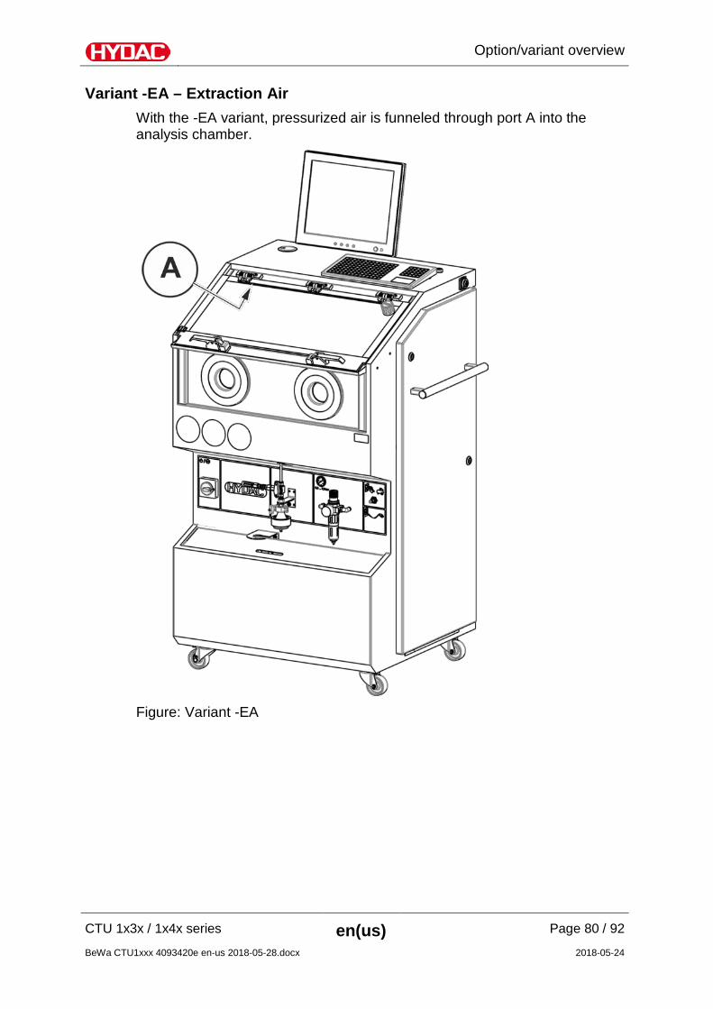
Option/variant overview
CTU 1x3x / 1x4x series en(us) Page 80 / 92
BeWa CTU1xxx 4093420e en-us 2018-05-28.docx 2018-05-24
Variant -EA – Extraction Air With the -EA variant, pressurized air is funneled through port A into the analysis chamber.
Figure: Variant -EA
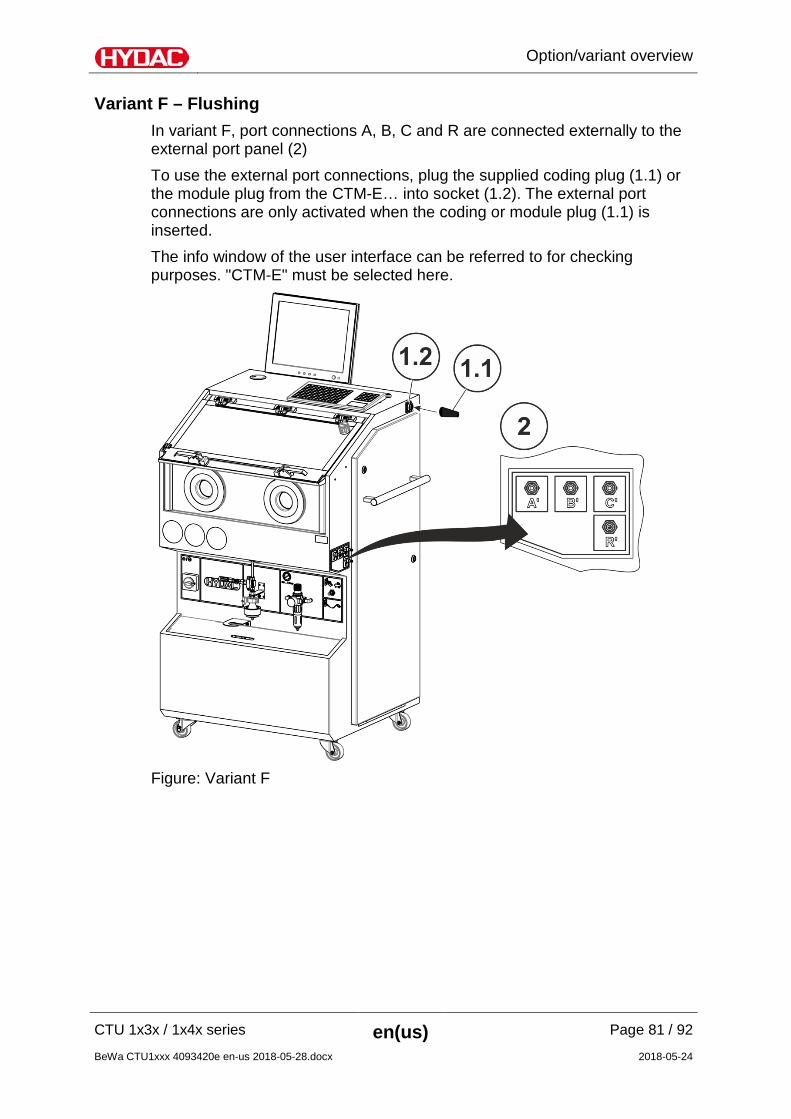
Option/variant overview
CTU 1x3x / 1x4x series en(us) Page 81 / 92
BeWa CTU1xxx 4093420e en-us 2018-05-28.docx 2018-05-24
Variant F – Flushing In variant F, port connections A, B, C and R are connected externally to the external port panel (2) To use the external port connections, plug the supplied coding plug (1.1) or the module plug from the CTM-E… into socket (1.2). The external port connections are only activated when the coding or module plug (1.1) is inserted. The info window of the user interface can be referred to for checking purposes. "CTM-E" must be selected here.
Figure: Variant F
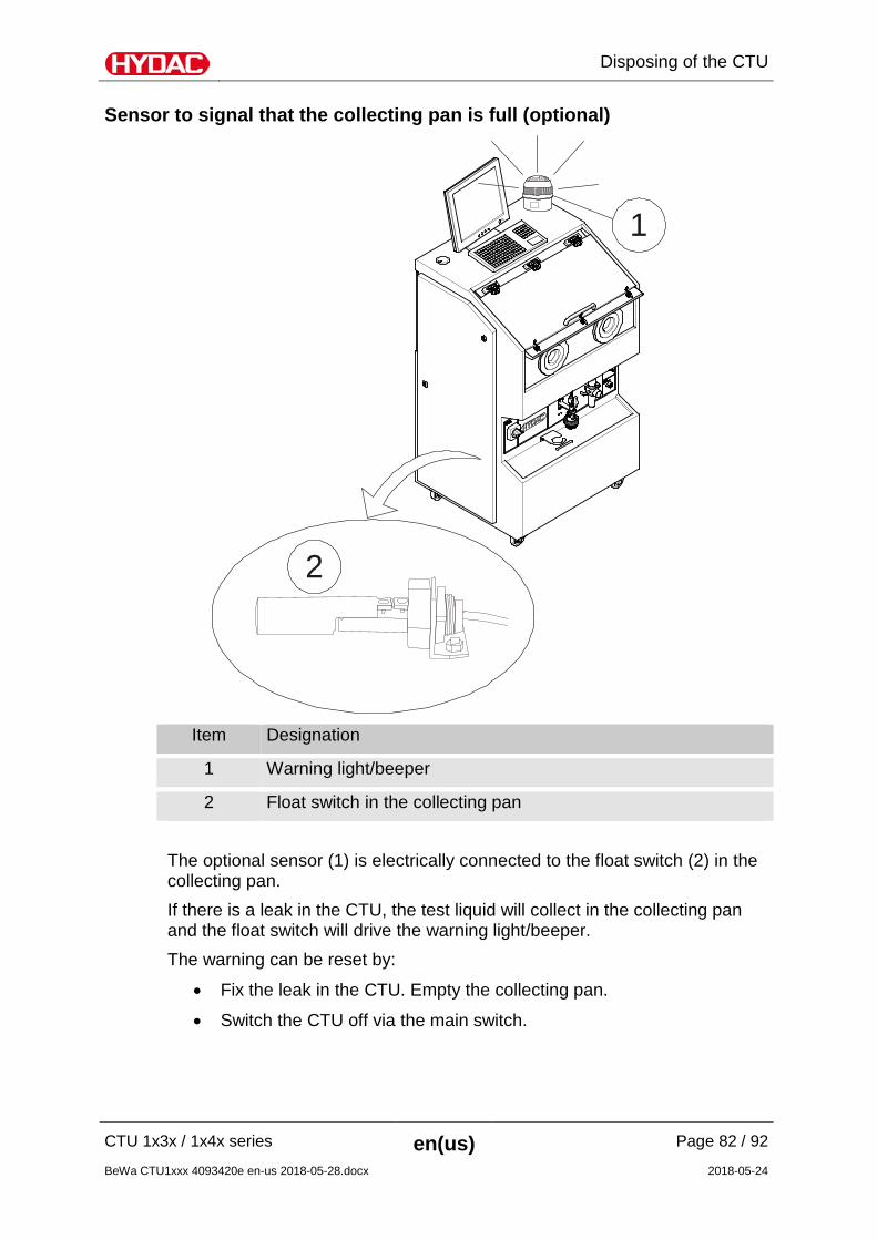
Disposing of the CTU
CTU 1x3x / 1x4x series en(us) Page 82 / 92
BeWa CTU1xxx 4093420e en-us 2018-05-28.docx 2018-05-24
Sensor to signal that the collecting pan is full (optional)
1
2
Item Designation
1 Warning light/beeper
2 Float switch in the collecting pan The optional sensor (1) is electrically connected to the float switch (2) in the collecting pan. If there is a leak in the CTU, the test liquid will collect in the collecting pan and the float switch will drive the warning light/beeper. The warning can be reset by:
• Fix the leak in the CTU. Empty the collecting pan.
• Switch the CTU off via the main switch.
Disposing of the CTU
CTU 1x3x / 1x4x series en(us) Page 83 / 92
BeWa CTU1xxx 4093420e en-us 2018-05-28.docx 2018-05-24
Disposing of the CTU
Dispose of the packaging material in an environmentally friendly manner. Drain the CTU completely. Dispose of the analysis fluid in an environmentally-friendly manner. Accordingly, follow the instructions in the safety data sheet for the analysis fluid. After dismantling the unit and separating the various materials, dispose of the unit in an environmentally-friendly manner.
Technical details
CTU 1x3x / 1x4x series en(us) Page 84 / 92
BeWa CTU1xxx 4093420e en-us 2018-05-28.docx 2018-05-24
Technical details
Dimensions CTU 1xxx
Height = 1800 mm
Width = 1000 mm
Depth = 900 mm
Dimensions CTU 12xx
Height = 1800 mm
Width = 1000 mm
Depth = 1100 mm
Weight when empty CTU 1xxx
≈ 270 kg
≈ 290 kg with ultrasound
Empty weight CTU 12xx
≈ 310 kg
≈ 330 kg with ultrasound
Load capacity ≤ 47.5 kg For evenly distributed load, no point loading
Nominal voltage 100 - 240 V AC (depending on model)
Nominal power 600 W
800 W with ultrasound Emission sound pressure level LPA < 70 db(A)
Permitted ambient temperature range 15 … 28 °C
Permitted storage temperature range 0 … 50 °C
Permitted ambient conditions for storage
dust-free, no salty air, not in the vicinity of oxidizing substances (flash rust, rust bloom)
Permitted relative air humidity ≤ 80 % (non condensing)
compressed air supply ≥ 6.5 bar Required compressed air volume ≈ 60 l/min
condition of compressed air dry and filtered
Required compressed air supply ≤ 5 µm
Attachment
CTU 1x3x / 1x4x series en(us) Page 85 / 92
BeWa CTU1xxx 4093420e en-us 2018-05-28.docx 2018-05-24
Pressure adjustment range 0.7 … 6.0 bar
Ultrasonic (optional)
Ultrasonic Performance 100 Watt
Ultrasonic frequency 40 kHz
Attachment
EC declaration of conformity The CE declaration of conformity can be found in the Technical Documentation of the CTU.
Customer Service/ Service If you have any questions, suggestions, or encounter any problems of a technical nature, please contact: HYDAC FILTER SYSTEMS GMBH Justus-von-Liebig Str., Werk 20 66280 Sulzbach / Saar Fax: +49 6897 509 9046 E-mail: [email protected]
For repair work or complaints/claims, please contact our central customer service department: HYDAC SYSTEMS & SERVICE GMBH Friedrichsthaler Straße 15, Werk 13 66540 Neunkirchen-Heinitz Telephone: +49 6897 509 883 Fax: +49 6897 509 324 E-mail: [email protected]
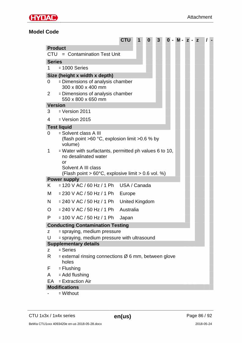
Attachment
CTU 1x3x / 1x4x series en(us) Page 86 / 92
BeWa CTU1xxx 4093420e en-us 2018-05-28.docx 2018-05-24
Model Code CTU 1 0 3 0 - M - z - z / -
Product CTU = Contamination Test Unit Series 1 = 1000 Series Size (height x width x depth) 0 = Dimensions of analysis chamber
300 x 800 x 400 mm
2 = Dimensions of analysis chamber 550 x 800 x 650 mm
Version 3 = Version 2011
4 = Version 2015 Test liquid 0 = Solvent class A III
(flash point >60 °C, explosion limit >0.6 % by volume)
1 = Water with surfactants, permitted ph values 6 to 10, no desalinated water or Solvent A III class (Flash point > 60°C, explosive limit > 0.6 vol. %)
Power supply K = 120 V AC / 60 Hz / 1 Ph USA / Canada
M = 230 V AC / 50 Hz / 1 Ph Europe
N = 240 V AC / 50 Hz / 1 Ph United Kingdom
O = 240 V AC / 50 Hz / 1 Ph Australia
P = 100 V AC / 50 Hz / 1 Ph Japan Conducting Contamination Testing z = spraying, medium pressure U = spraying, medium pressure with ultrasound Supplementary details z = Series R = external rinsing connections Ø 6 mm, between glove
holes
F = Flushing A = Add flushing EA = Extraction Air Modifications - = Without
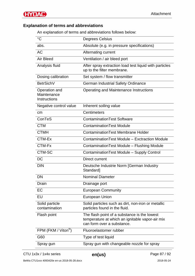
Attachment
CTU 1x3x / 1x4x series en(us) Page 87 / 92
BeWa CTU1xxx 4093420e en-us 2018-05-28.docx 2018-05-24
Explanation of terms and abbreviations An explanation of terms and abbreviations follows below:
°C Degrees Celsius
abs. Absolute (e.g. in pressure specifications)
AC Alternating current
Air Bleed Ventilation / air bleed port
Analysis fluid After spray extraction load test liquid with particles up to the filter membrane.
Dosing calibration Set system / flow transmitter
BetrSichV German Industrial Safety Ordinance
Operation and Maintenance Instructions
Operating and Maintenance Instructions
Negative control value Inherent soiling value
cm Centimeters
ConTeS ContaminationTest Software
CTM ContaminationTest Module
CTMH ContaminationTest Membrane Holder
CTM-Ex ContaminationTest Module – Exctraction Module
CTM-Fx ContaminationTest Module – Flushing Module
CTM-SC ContaminationTest Module – Supply Control
DC Direct current
DIN Deutsche Industrie Norm [German Industry Standard]
DN Nominal Diameter
Drain Drainage port
EC European Community
EU European Union
Solid particle contamination
Solid particles such as dirt, non-iron or metallic particles found in the fluid.
Flash point The flash point of a substance is the lowest temperature at which an ignitable vapor-air mix can form over a substance.
FPM (FKM / Viton®) Fluoroelastomer rubber
G60 Type of test liquid
Spray gun Spray gun with changeable nozzle for spray
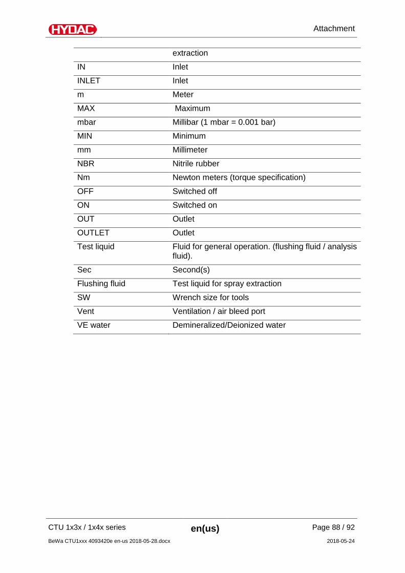
Attachment
CTU 1x3x / 1x4x series en(us) Page 88 / 92
BeWa CTU1xxx 4093420e en-us 2018-05-28.docx 2018-05-24
extraction
IN Inlet
INLET Inlet
m Meter
MAX Maximum
mbar Millibar (1 mbar = 0.001 bar)
MIN Minimum
mm Millimeter
NBR Nitrile rubber
Nm Newton meters (torque specification)
OFF Switched off
ON Switched on
OUT Outlet
OUTLET Outlet
Test liquid Fluid for general operation. (flushing fluid / analysis fluid).
Sec Second(s)
Flushing fluid Test liquid for spray extraction
SW Wrench size for tools
Vent Ventilation / air bleed port
VE water Demineralized/Deionized water
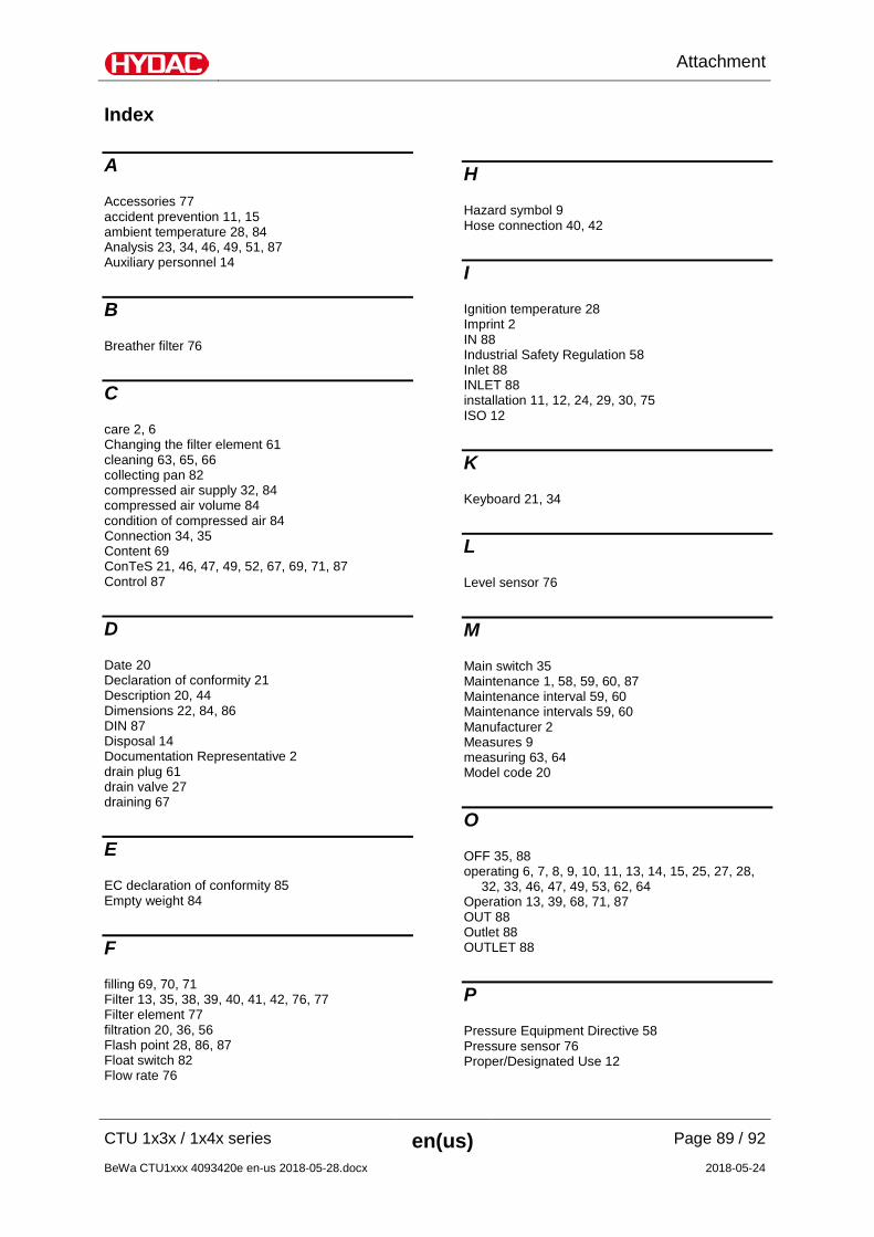
Attachment
CTU 1x3x / 1x4x series en(us) Page 89 / 92
BeWa CTU1xxx 4093420e en-us 2018-05-28.docx 2018-05-24
Index
A
Accessories 77 accident prevention 11, 15 ambient temperature 28, 84 Analysis 23, 34, 46, 49, 51, 87 Auxiliary personnel 14
B
Breather filter 76
C
care 2, 6 Changing the filter element 61 cleaning 63, 65, 66 collecting pan 82 compressed air supply 32, 84 compressed air volume 84 condition of compressed air 84 Connection 34, 35 Content 69 ConTeS 21, 46, 47, 49, 52, 67, 69, 71, 87 Control 87
D
Date 20 Declaration of conformity 21 Description 20, 44 Dimensions 22, 84, 86 DIN 87 Disposal 14 Documentation Representative 2 drain plug 61 drain valve 27 draining 67
E
EC declaration of conformity 85 Empty weight 84
F
filling 69, 70, 71 Filter 13, 35, 38, 39, 40, 41, 42, 76, 77 Filter element 77 filtration 20, 36, 56 Flash point 28, 86, 87 Float switch 82 Flow rate 76
H
Hazard symbol 9 Hose connection 40, 42
I
Ignition temperature 28 Imprint 2 IN 88 Industrial Safety Regulation 58 Inlet 88 INLET 88 installation 11, 12, 24, 29, 30, 75 ISO 12
K
Keyboard 21, 34
L
Level sensor 76
M
Main switch 35 Maintenance 1, 58, 59, 60, 87 Maintenance interval 59, 60 Maintenance intervals 59, 60 Manufacturer 2 Measures 9 measuring 63, 64 Model code 20
O
OFF 35, 88 operating 6, 7, 8, 9, 10, 11, 13, 14, 15, 25, 27, 28,
32, 33, 46, 47, 49, 53, 62, 64 Operation 13, 39, 68, 71, 87 OUT 88 Outlet 88 OUTLET 88
P
Pressure Equipment Directive 58 Pressure sensor 76 Proper/Designated Use 12
Attachment
CTU 1x3x / 1x4x series en(us) Page 90 / 92
BeWa CTU1xxx 4093420e en-us 2018-05-28.docx 2018-05-24
R
replacement 67 return line filter 16, 19, 61, 67 Rigid caster 34
S
Safety Data Sheet 28 select 7, 53 Sensor 82 Service 64, 85 Signal word 8, 9 signal words 8, 9 Size 86 Solid particle contamination 87 Spare part 76 Spare parts 76 Spare parts list 76 Specialist personnel 11, 14 switching off 53 switching on 45
T
Temperature 50 Temperature sensor 50 Transport 14 transporting 34 troubleshooting 14
U
USB 34
V
venting 28, 57
W
Weight 84 work equipment 58


HYDAC FILTER SYSTEMS GMBH Industriegebiet Postfach 1251 66280 Sulzbach/Saar 66273 Sulzbach/Saar Germany Germany Tel: +49 6897 509 01 Central Fax: +49 6897 509 9046 Technology Fax: +49 6897 509 577 Sales Department Internet: www.hydac.com E-mail: [email protected]
Recommended