Consumer-Applicable Retroreflective Microspheres for Use in Polyester Fabrics
By: Omar Abdullah, Megan Lilley, Drew Stasak, Dan Tamayo, Kevin Toula, Lexi Willingham
ENMA 490 Capstone Design
Abstract
Our report will discuss how our team decided upon our design project and the
approach we took to meet our design goals. We have designed an assembly of
retroreflective barium titanate (BaTiO3) microspheres immersed in a hot-melt adhesive.
The BaTiO3 microspheres are hemispherically-coated with aluminum and have a radius
of 50 μm. Through heating, the assembly can be attached to polyester clothing. If a
pedestrian wears clothing with our retroreflective assembly, they will be more readily
visible at night to a driver of a car. While some retroreflective products exist, we decided
to make an customer-applicable adhesive to have minimal visibility in ambient lighting,
but maximal visibility at night. This type of product is not currently on the market. The
design approach included materials selection, process formation, ray tracing, and
calculations to show how our retroreflective adhesive would function in accordance with
the light given off by car headlights. The optimal divergence angle for our scenario was
calculated to be 0.697 degrees.
Motivation
Being a student at the University of Maryland over the past couple years has
meant experiencing many changes aiming to improve pedestrian safety. Sadly, these
changes were not preventative measures, but the result of the tragedies our community
has felt with the hopes that any future accidents would be avoided. Pedestrian injuries
due to automobiles occur about every eight minutes, with the majority of these
happening at night [1]. It is extremely difficult to notice people walking along or near the
side of the road at nighttime until the car is right behind them, when it may be too late to
avoid an accident. The most difficult times to see a pedestrian at night are when there
are no sidewalks, crosswalks, or streetlights. In these cases, it would be extremely
helpful and possibly life-saving if pedestrians were visible to a driver at a safe distance.
Retroreflective technology would be beneficial in these situations because the clothing
would reflect when a light was shining on it.
Retroreflection is a phenomenon in which a material will reflect light parallel back
to its source. If retroreflective materials were used in clothing, when a car’s headlight hits
the person, they would become noticeable to the driver at a safe distance away. This
would potentially lead to fewer accidents between cars and pedestrians.
Materials Science and Engineering Aspects
This project required many skills we acquired throughout our time as
undergraduate students in the Department of Materials Science and Engineering. We
used knowledge in the areas of physics, chemistry and engineering, most importantly
focusing on polymers, optics and processing techniques. For our design, we chose the
materials for our microsphere and hemispherical coating based on optical properties like
index of refraction and reflectivity. Later, we needed a knowledge of polymers in order to
choose our adhesives based on temperature properties and bonding strengths. We
considered the strength of adhesion of the chosen hot melt polyurethane to both the
microspheres and the polyester fabric to ensure the durability of our product. One of the
processing techniques that we utilized in our manufacturing design was sputter
deposition. Lastly, we used ray tracing and calculations to simulate the retroreflection of
our chosen microspheres. This was an important aspect of our design, as part of our
goal was to maximize the light reflected back into the eyes of the driver.
Previous Work
Currently, there are two main categories of retroreflective clothing. The first
category is fluorescent clothing with retroreflective strips. This type of clothing is
commonly worn by construction and other roadside workers as well as hunters. Many
people are not inclined to wear this type of clothing unless it is required, due to its
relatively unappealing visual appearance. The fluorescent colors are bright and
noticeable during the day; however, at night they do not have the same effect. Although
bright colors are more noticeable at night than dark colors, visibility problems still result
as they would with any normal clothing. The retroreflective strips are needed in order for
the clothing to be visible at night. The second category of retroreflective clothing is
athleticwear. This type of clothing is designed so they are not constantly reflecting light,
only when light with enough light intensity, like a car’s headlights compared to ambient
lighting inside a room, is shining on the article of clothing. A disadvantage of these types
of clothes are their very limited style and select consumer market. Since these
retroreflective clothes are fairly new to the market, not many companies offer them as
options, so these clothes tend to be expensive. The basis of our design project is the
combination of the effects of these clothing options. Our goal is to have the
retroreflectivity of the first category with the aesthetic appearance of the second
category.
The retroreflective materials currently used are glass microspheres, although
they can be other shapes such as prismatic cube-corners [2]. To increase the
retroreflectivity, the glass is sometimes coated. Commonly used materials are barium
titanate coated in aluminum [3]. 3MTM Scotchlite is the most well-known and widely used
retroreflective material that uses this technology. The current technology for the athletic
wear is similar, but the athletic companies have found ways to incorporate the
retroreflectors in large portions covering most or all of the article of clothing as opposed
to 3MTM Scotchlite which tends to be used in small, strategic areas.
Design Goals
The desire to improve pedestrian safety at night led us to look for a way to
improve pedestrian visibility to a driver in a car. In order to accomplish this, we set out to
create a retroreflective adhesive that a customer can apply to their own clothes easily.
The retroreflective material must not be highly visible in natural lighting to differentiate
our design from the current retroreflective material available. The application of the
retroflecting material should have a minimal effect on the clothing’s look and feel; the
product is intended only to be seen when exposed to a direct, intense light source.
Technical Approach
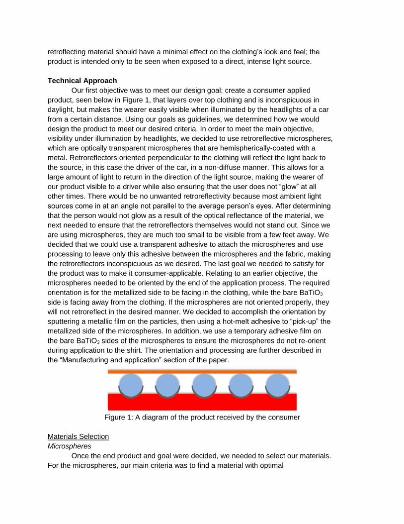
Our first objective was to meet our design goal; create a consumer applied
product, seen below in Figure 1, that layers over top clothing and is inconspicuous in
daylight, but makes the wearer easily visible when illuminated by the headlights of a car
from a certain distance. Using our goals as guidelines, we determined how we would
design the product to meet our desired criteria. In order to meet the main objective,
visibility under illumination by headlights, we decided to use retroreflective microspheres,
which are optically transparent microspheres that are hemispherically-coated with a
metal. Retroreflectors oriented perpendicular to the clothing will reflect the light back to
the source, in this case the driver of the car, in a non-diffuse manner. This allows for a
large amount of light to return in the direction of the light source, making the wearer of
our product visible to a driver while also ensuring that the user does not “glow” at all
other times. There would be no unwanted retroreflectivity because most ambient light
sources come in at an angle not parallel to the average person’s eyes. After determining
that the person would not glow as a result of the optical reflectance of the material, we
next needed to ensure that the retroreflectors themselves would not stand out. Since we
are using microspheres, they are much too small to be visible from a few feet away. We
decided that we could use a transparent adhesive to attach the microspheres and use
processing to leave only this adhesive between the microspheres and the fabric, making
the retroreflectors inconspicuous as we desired. The last goal we needed to satisfy for
the product was to make it consumer-applicable. Relating to an earlier objective, the
microspheres needed to be oriented by the end of the application process. The required
orientation is for the metallized side to be facing in the clothing, while the bare BaTiO3
side is facing away from the clothing. If the microspheres are not oriented properly, they
will not retroreflect in the desired manner. We decided to accomplish the orientation by
sputtering a metallic film on the particles, then using a hot-melt adhesive to “pick-up” the
metallized side of the microspheres. In addition, we use a temporary adhesive film on
the bare BaTiO3 sides of the microspheres to ensure the microspheres do not re-orient
during application to the shirt. The orientation and processing are further described in
the “Manufacturing and application” section of the paper.
Figure 1: A diagram of the product received by the consumer
Materials Selection
Microspheres
Once the end product and goal were decided, we needed to select our materials.
For the microspheres, our main criteria was to find a material with optimal
retroreflectivity. There are two main types of retroreflector shapes, cube corners and
spheres. Cube corners are best manufactured in rows, but we chose to use
microspheres in order to have individual particles that would be less visible. Thus we
needed to choose a material for the sphere. To determine what materials work best as
retroreflecting spheres we equated the scenario to a ball lens with an effective focal
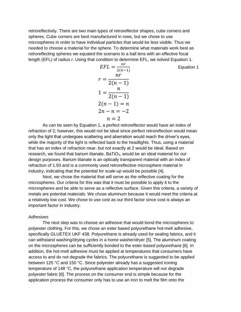
length (EFL) of radius r. Using that condition to determine EFL, we solved Equation 1.
𝐸𝐹𝐿 =𝑛𝑟
2(𝑛−1) Equation 1
𝑟 =𝑛𝑟
2(𝑛 − 1)
1 =𝑛
2(𝑛 − 1)
2(𝑛 − 1) = 𝑛
2𝑛 − 𝑛 = −2
𝑛 = 2
As can be seen by Equation 1, a perfect retroreflector would have an index of
refraction of 2; however, this would not be ideal since perfect retroreflection would mean
only the light that undergoes scattering and aberration would reach the driver’s eyes,
while the majority of the light is reflected back to the headlights. Thus, using a material
that has an index of refraction near, but not exactly at 2 would be ideal. Based on
research, we found that barium titanate, BaTiO3, would be an ideal material for our
design purposes. Barium titanate is an optically transparent material with an index of
refraction of 1.93 and is a commonly used retroreflective microsphere material in
industry, indicating that the potential for scale-up would be possible [4].
Next, we chose the material that will serve as the reflective coating for the
microspheres. Our criteria for this was that it must be possible to apply it to the
microspheres and be able to serve as a reflective surface. Given this criteria, a variety of
metals are potential materials. We chose aluminum because it would meet the criteria at
a relatively low cost. We chose to use cost as our third factor since cost is always an
important factor in industry.
Adhesives
The next step was to choose an adhesive that would bond the microspheres to
polyester clothing. For this, we chose an ester based polyurethane hot-melt adhesive,
specifically GLUETEX UKF 438. Polyurethane is already used for sealing fabrics, and it
can withstand washing/drying cycles in a home washer/dryer [5]. The aluminum coating
on the microspheres can be sufficiently bonded to the ester-based polyurethane [6]. In
addition, the hot-melt adhesive must be applied at temperatures that consumers have
access to and do not degrade the fabrics. The polyurethane is suggested to be applied
between 125 °C and 150 °C. Since polyester already has a suggested ironing
temperature of 148 °C, the polyurethane application temperature will not degrade
polyester fabric [6]. The process on the consumer end is simple because for the
application process the consumer only has to use an iron to melt the film onto the
clothing, let it cool, and peel off a temporary adhesive layer.
When we incorporated the temporary adhesive layer into our design, our need for
an easily removable adhesive with a very high resistance to heat led us to choose a
Kapton® polyimide film and silicone adhesion. The temperature use range given in a
technical data sheet given by 3MTM is -73°C to 260°C [7]. Although the strength of
adhesion is only given for adhesion between the polyimide and steel, the technical data
sheet claims that their tape is easily removable and the high temperature performance
helps reduce adhesive transfer. The fact that the polyimide is easily removable would
prevent any pieces of the adhesive from remaining on the microspheres and interfering
with the retroreflection. The only other confirmation of this choice that we need is a
comparison to the strength of adhesion between the the hot melt and
microspheres.Given the fact that the strength of adhesion is weaker between the
polyimide film and the BaTiO3, the removal of this film will not affect the microsphere
attachment or orientation [7]. We could not collect enough data on the interfacial energy
between the polyimide film and the BaTiO3 microspheres to calculate the strength of
adhesion using JKR theory, so this would have to be determined in the prototype and
testing phase.
Manufacturing and Application
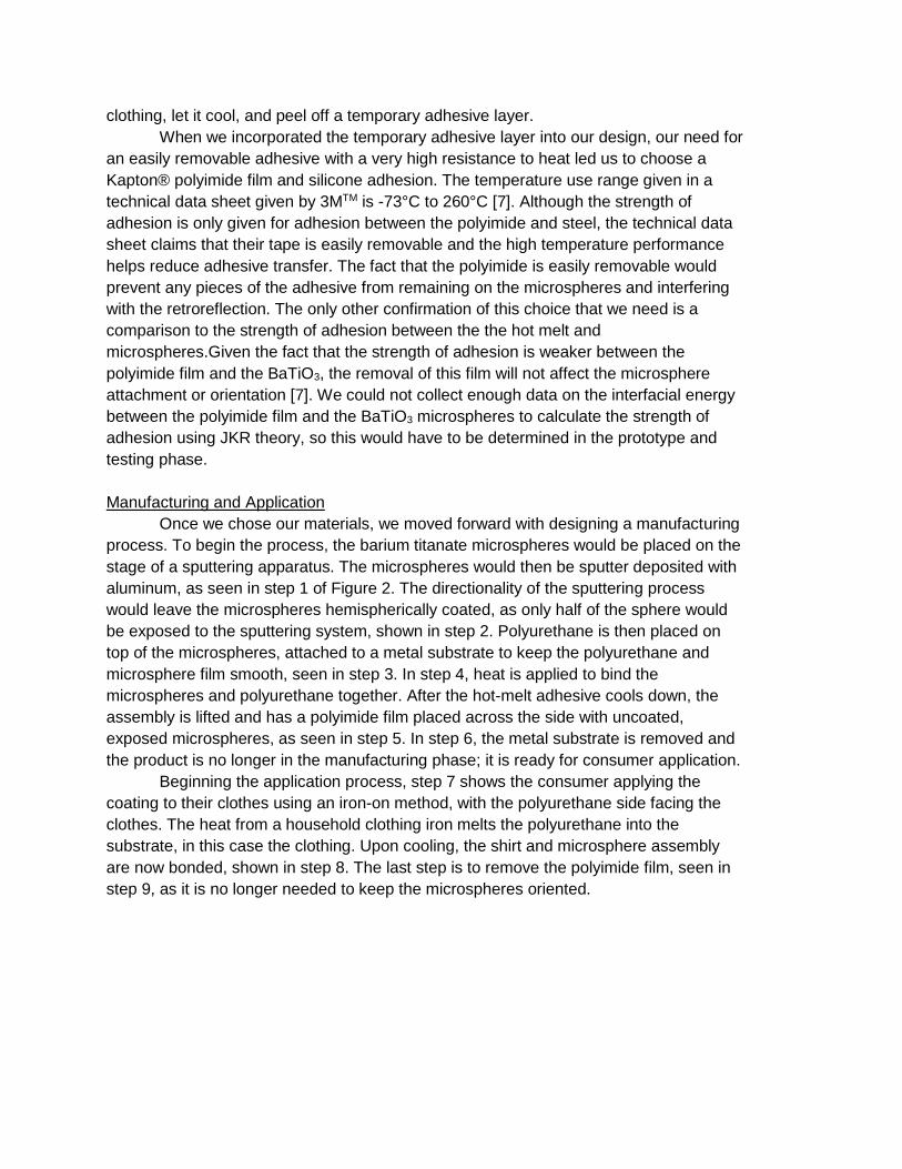
Once we chose our materials, we moved forward with designing a manufacturing
process. To begin the process, the barium titanate microspheres would be placed on the
stage of a sputtering apparatus. The microspheres would then be sputter deposited with
aluminum, as seen in step 1 of Figure 2. The directionality of the sputtering process
would leave the microspheres hemispherically coated, as only half of the sphere would
be exposed to the sputtering system, shown in step 2. Polyurethane is then placed on
top of the microspheres, attached to a metal substrate to keep the polyurethane and
microsphere film smooth, seen in step 3. In step 4, heat is applied to bind the
microspheres and polyurethane together. After the hot-melt adhesive cools down, the
assembly is lifted and has a polyimide film placed across the side with uncoated,
exposed microspheres, as seen in step 5. In step 6, the metal substrate is removed and
the product is no longer in the manufacturing phase; it is ready for consumer application.
Beginning the application process, step 7 shows the consumer applying the
coating to their clothes using an iron-on method, with the polyurethane side facing the
clothes. The heat from a household clothing iron melts the polyurethane into the
substrate, in this case the clothing. Upon cooling, the shirt and microsphere assembly
are now bonded, shown in step 8. The last step is to remove the polyimide film, seen in
step 9, as it is no longer needed to keep the microspheres oriented.
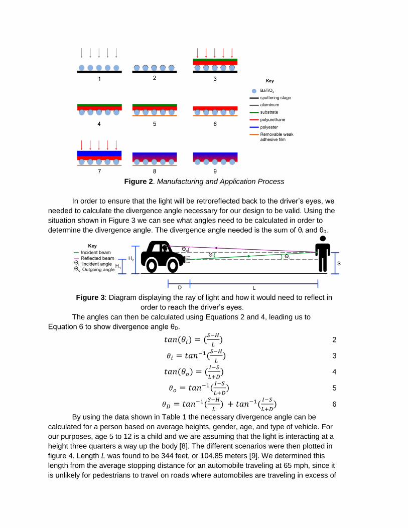
Figure 2. Manufacturing and Application Process
In order to ensure that the light will be retroreflected back to the driver’s eyes, we
needed to calculate the divergence angle necessary for our design to be valid. Using the
situation shown in Figure 3 we can see what angles need to be calculated in order to
determine the divergence angle. The divergence angle needed is the sum of θi and θ0.
Figure 3: Diagram displaying the ray of light and how it would need to reflect in
order to reach the driver’s eyes.
The angles can then be calculated using Equations 2 and 4, leading us to
Equation 6 to show divergence angle θD.
𝑡𝑎𝑛(𝜃𝑖) = (𝑆−𝐻
𝐿) 2
𝜃𝑖 = 𝑡𝑎𝑛−1(𝑆−𝐻
𝐿) 3
𝑡𝑎𝑛(𝜃𝑜) = (𝐼−𝑆
𝐿+𝐷) 4
𝜃𝑜 = 𝑡𝑎𝑛−1(𝐼−𝑆
𝐿+𝐷) 5
𝜃𝐷 = 𝑡𝑎𝑛−1(𝑆−𝐻
𝐿) + 𝑡𝑎𝑛−1(
𝐼−𝑆
𝐿+𝐷) 6
By using the data shown in Table 1 the necessary divergence angle can be
calculated for a person based on average heights, gender, age, and type of vehicle. For
our purposes, age 5 to 12 is a child and we are assuming that the light is interacting at a
height three quarters a way up the body [8]. The different scenarios were then plotted in
figure 4. Length L was found to be 344 feet, or 104.85 meters [9]. We determined this
length from the average stopping distance for an automobile traveling at 65 mph, since it
is unlikely for pedestrians to travel on roads where automobiles are traveling in excess of
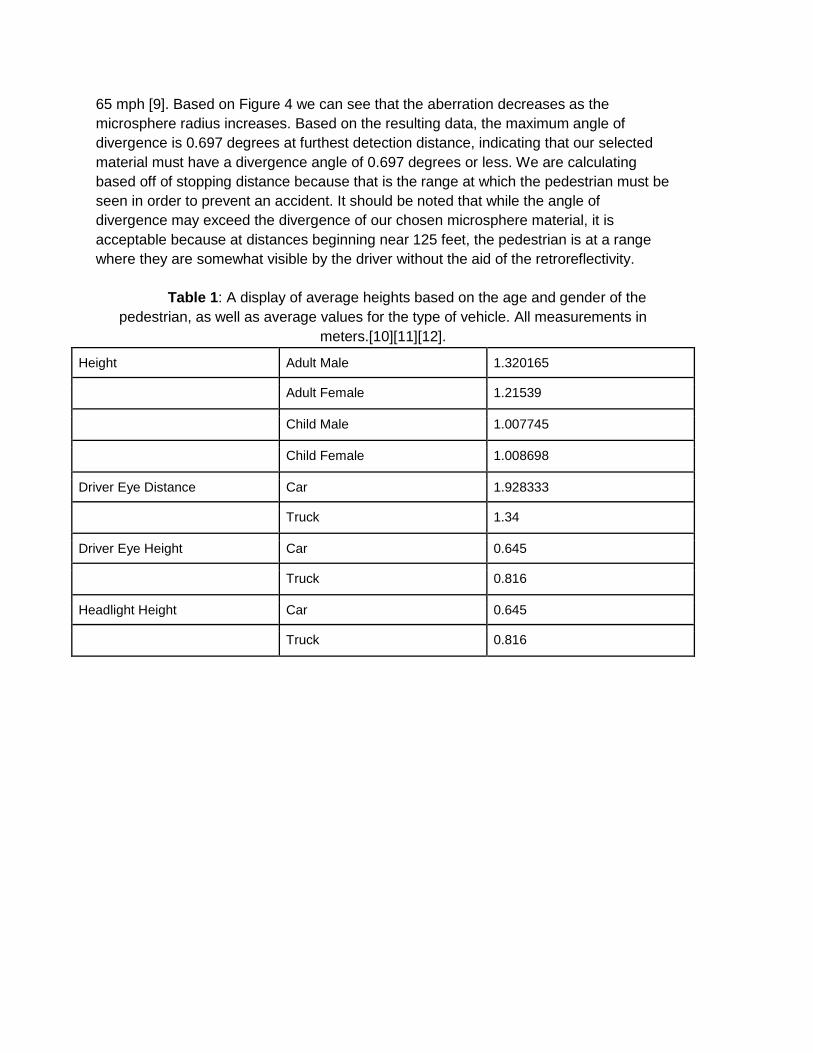
65 mph [9]. Based on Figure 4 we can see that the aberration decreases as the
microsphere radius increases. Based on the resulting data, the maximum angle of
divergence is 0.697 degrees at furthest detection distance, indicating that our selected
material must have a divergence angle of 0.697 degrees or less. We are calculating
based off of stopping distance because that is the range at which the pedestrian must be
seen in order to prevent an accident. It should be noted that while the angle of
divergence may exceed the divergence of our chosen microsphere material, it is
acceptable because at distances beginning near 125 feet, the pedestrian is at a range
where they are somewhat visible by the driver without the aid of the retroreflectivity.
Table 1: A display of average heights based on the age and gender of the
pedestrian, as well as average values for the type of vehicle. All measurements in
meters.[10][11][12].
Height Adult Male 1.320165
Adult Female 1.21539
Child Male 1.007745
Child Female 1.008698
Driver Eye Distance Car 1.928333
Truck 1.34
Driver Eye Height Car 0.645
Truck 0.816
Headlight Height Car 0.645
Truck 0.816
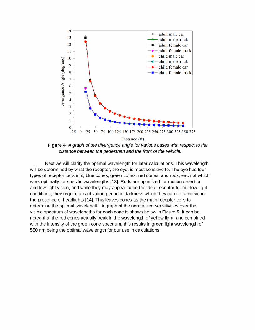
Figure 4: A graph of the divergence angle for various cases with respect to the
distance between the pedestrian and the front of the vehicle.
Next we will clarify the optimal wavelength for later calculations. This wavelength
will be determined by what the receptor, the eye, is most sensitive to. The eye has four
types of receptor cells in it; blue cones, green cones, red cones, and rods, each of which
work optimally for specific wavelengths [13]. Rods are optimized for motion detection
and low-light vision, and while they may appear to be the ideal receptor for our low-light
conditions, they require an activation period in darkness which they can not achieve in
the presence of headlights [14]. This leaves cones as the main receptor cells to
determine the optimal wavelength. A graph of the normalized sensitivities over the
visible spectrum of wavelengths for each cone is shown below in Figure 5. It can be
noted that the red cones actually peak in the wavelength of yellow light, and combined
with the intensity of the green cone spectrum, this results in green light wavelength of
550 nm being the optimal wavelength for our use in calculations.
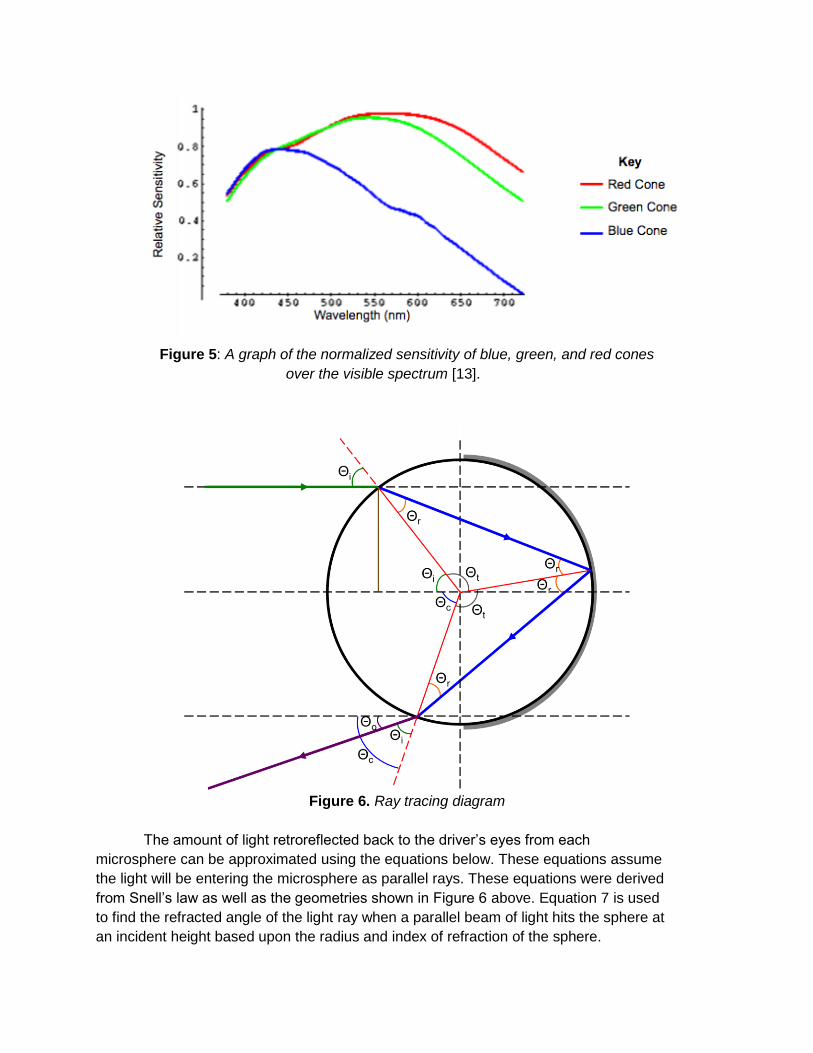
Figure 5: A graph of the normalized sensitivity of blue, green, and red cones
over the visible spectrum [13].
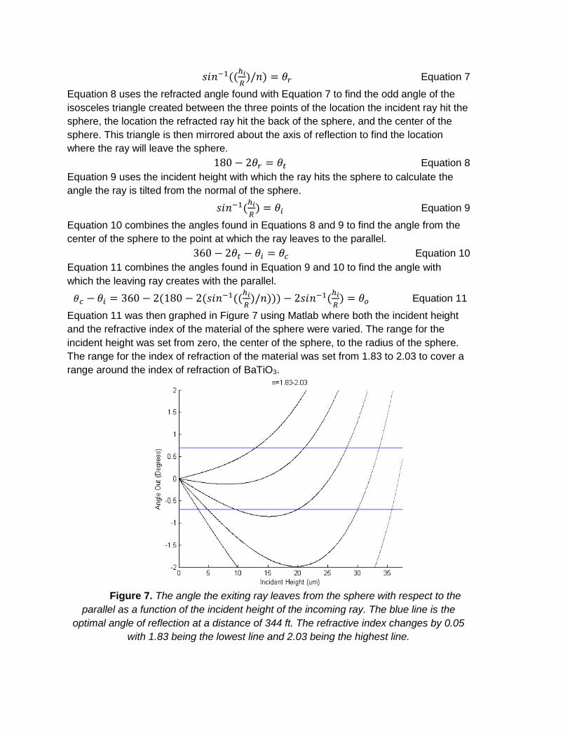
Figure 6. Ray tracing diagram
The amount of light retroreflected back to the driver’s eyes from each
microsphere can be approximated using the equations below. These equations assume
the light will be entering the microsphere as parallel rays. These equations were derived
from Snell’s law as well as the geometries shown in Figure 6 above. Equation 7 is used
to find the refracted angle of the light ray when a parallel beam of light hits the sphere at
an incident height based upon the radius and index of refraction of the sphere.
𝑠𝑖𝑛−1((ℎ𝑖
𝑅)/𝑛) = 𝜃𝑟 Equation 7
Equation 8 uses the refracted angle found with Equation 7 to find the odd angle of the
isosceles triangle created between the three points of the location the incident ray hit the
sphere, the location the refracted ray hit the back of the sphere, and the center of the
sphere. This triangle is then mirrored about the axis of reflection to find the location
where the ray will leave the sphere.
180 − 2𝜃𝑟 = 𝜃𝑡 Equation 8
Equation 9 uses the incident height with which the ray hits the sphere to calculate the
angle the ray is tilted from the normal of the sphere.
𝑠𝑖𝑛−1(ℎ𝑖
𝑅) = 𝜃𝑖 Equation 9
Equation 10 combines the angles found in Equations 8 and 9 to find the angle from the
center of the sphere to the point at which the ray leaves to the parallel.
360 − 2𝜃𝑡 − 𝜃𝑖 = 𝜃𝑐 Equation 10
Equation 11 combines the angles found in Equation 9 and 10 to find the angle with
which the leaving ray creates with the parallel.
𝜃𝑐 − 𝜃𝑖 = 360 − 2(180 − 2(𝑠𝑖𝑛−1((ℎ𝑖
𝑅)/𝑛))) − 2𝑠𝑖𝑛−1(
ℎ𝑖
𝑅) = 𝜃𝑜 Equation 11
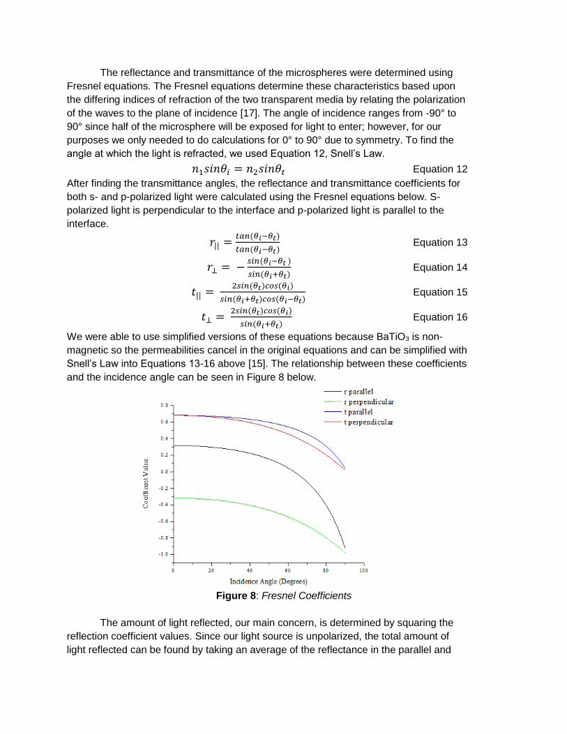
Equation 11 was then graphed in Figure 7 using Matlab where both the incident height
and the refractive index of the material of the sphere were varied. The range for the
incident height was set from zero, the center of the sphere, to the radius of the sphere.
The range for the index of refraction of the material was set from 1.83 to 2.03 to cover a
range around the index of refraction of BaTiO3.
Figure 7. The angle the exiting ray leaves from the sphere with respect to the
parallel as a function of the incident height of the incoming ray. The blue line is the
optimal angle of reflection at a distance of 344 ft. The refractive index changes by 0.05
with 1.83 being the lowest line and 2.03 being the highest line.
The reflectance and transmittance of the microspheres were determined using
Fresnel equations. The Fresnel equations determine these characteristics based upon
the differing indices of refraction of the two transparent media by relating the polarization
of the waves to the plane of incidence [17]. The angle of incidence ranges from -90° to
90° since half of the microsphere will be exposed for light to enter; however, for our
purposes we only needed to do calculations for 0° to 90° due to symmetry. To find the
angle at which the light is refracted, we used Equation 12, Snell’s Law.
𝑛1𝑠𝑖𝑛𝜃𝑖 = 𝑛2𝑠𝑖𝑛𝜃𝑡 Equation 12
After finding the transmittance angles, the reflectance and transmittance coefficients for
both s- and p-polarized light were calculated using the Fresnel equations below. S-
polarized light is perpendicular to the interface and p-polarized light is parallel to the
interface.
𝑟|| =𝑡𝑎𝑛(𝜃𝑖−𝜃𝑡)
𝑡𝑎𝑛(𝜃𝑖−𝜃𝑡) Equation 13
𝑟⊥ = −𝑠𝑖𝑛(𝜃𝑖−𝜃𝑡 )
𝑠𝑖𝑛(𝜃𝑖+𝜃𝑡) Equation 14
𝑡|| = 2𝑠𝑖𝑛(𝜃𝑡)𝑐𝑜𝑠(𝜃𝑖)
𝑠𝑖𝑛(𝜃𝑖+𝜃𝑡)𝑐𝑜𝑠(𝜃𝑖−𝜃𝑡) Equation 15
𝑡⊥ = 2𝑠𝑖𝑛(𝜃𝑡)𝑐𝑜𝑠(𝜃𝑖)
𝑠𝑖𝑛(𝜃𝑖+𝜃𝑡) Equation 16
We were able to use simplified versions of these equations because BaTiO3 is non-
magnetic so the permeabilities cancel in the original equations and can be simplified with
Snell’s Law into Equations 13-16 above [15]. The relationship between these coefficients
and the incidence angle can be seen in Figure 8 below.
Figure 8: Fresnel Coefficients
The amount of light reflected, our main concern, is determined by squaring the
reflection coefficient values. Since our light source is unpolarized, the total amount of
light reflected can be found by taking an average of the reflectance in the parallel and
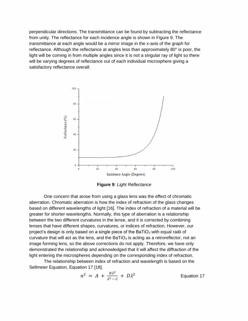
perpendicular directions. The transmittance can be found by subtracting the reflectance
from unity. The reflectance for each incidence angle is shown in Figure 9. The
transmittance at each angle would be a mirror image in the x-axis of the graph for
reflectance. Although the reflectance at angles less than approximately 80° is poor, the
light will be coming in from multiple angles since it is not a singular ray of light so there
will be varying degrees of reflectance out of each individual microsphere giving a
satisfactory reflectance overall.
Figure 9: Light Reflectance
One concern that arose from using a glass lens was the effect of chromatic
aberration. Chromatic aberration is how the index of refraction of the glass changes
based on different wavelengths of light [16]. The index of refraction of a material will be
greater for shorter wavelengths. Normally, this type of aberration is a relationship
between the two different curvatures in the lense, and it is corrected by combining
lenses that have different shapes, curvatures, or indices of refraction. However, our
project’s design is only based on a single piece of the BaTiO3 with equal radii of
curvature that will act as the lens, and the BaTiO3 is acting as a retroreflector, not an
image forming lens, so the above corrections do not apply. Therefore, we have only
demonstrated the relationship and acknowledged that it will affect the diffraction of the
light entering the microspheres depending on the corresponding index of refraction.
The relationship between index of refraction and wavelength is based on the
Sellmeier Equation, Equation 17 [18].
𝑛2 = 𝐴 + 𝐵𝜆2
𝜆2 − 𝐶 + 𝐷𝜆2 Equation 17
The variable constants A, B, C, and D depend on the material and are
determined through experimental fits. The corresponding values of A, B, C, and D for
BaTiO3 are 3.0584, 2.27326, 0.07409, and -0.02428 respectively [18]. This data is given
for BaTiO3 in general and not the specific BaTiO3 we would have purchased had we
decided to prototype our design. The BaTiO3 microspheres we would have purchased
have an index of refraction of 1.93. There are a range of possible indices of refraction
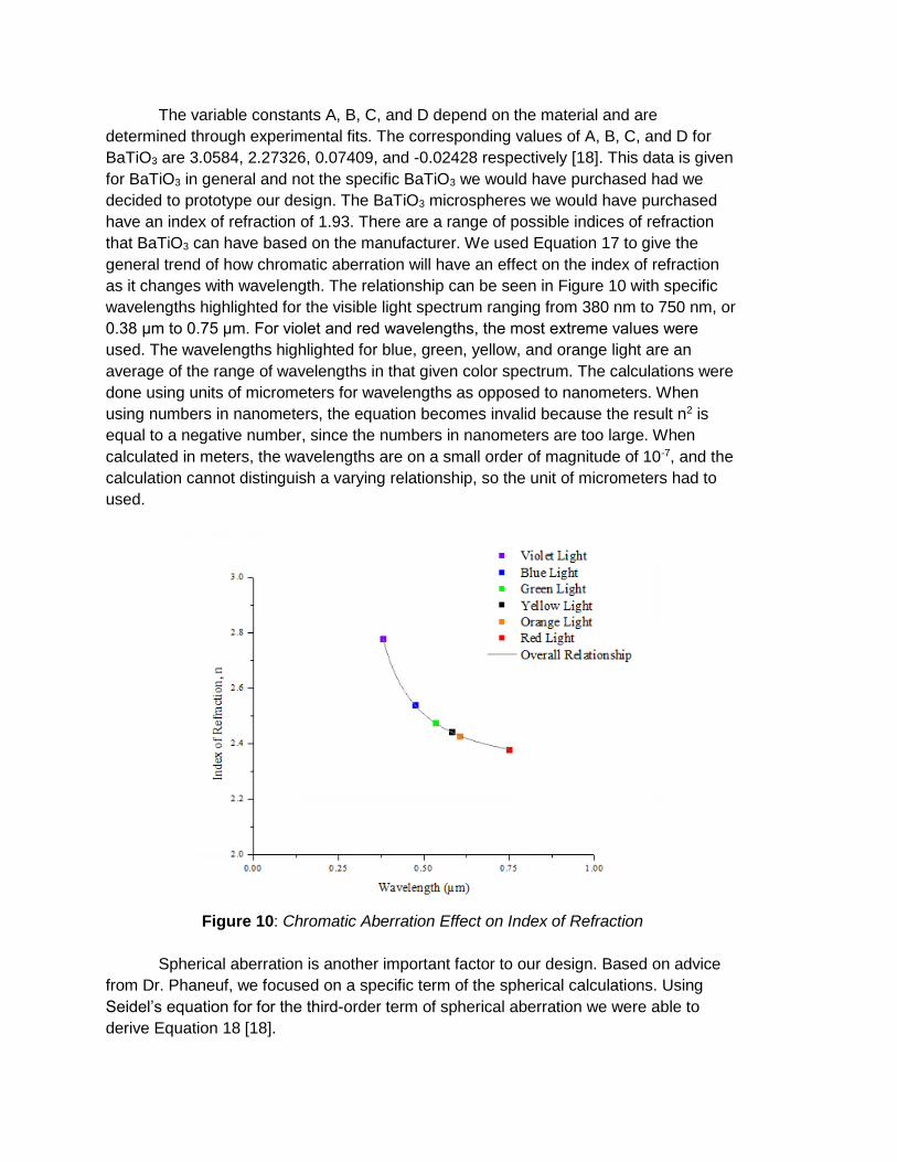
that BaTiO3 can have based on the manufacturer. We used Equation 17 to give the
general trend of how chromatic aberration will have an effect on the index of refraction
as it changes with wavelength. The relationship can be seen in Figure 10 with specific
wavelengths highlighted for the visible light spectrum ranging from 380 nm to 750 nm, or
0.38 μm to 0.75 μm. For violet and red wavelengths, the most extreme values were
used. The wavelengths highlighted for blue, green, yellow, and orange light are an
average of the range of wavelengths in that given color spectrum. The calculations were
done using units of micrometers for wavelengths as opposed to nanometers. When
using numbers in nanometers, the equation becomes invalid because the result n2 is
equal to a negative number, since the numbers in nanometers are too large. When
calculated in meters, the wavelengths are on a small order of magnitude of 10-7, and the
calculation cannot distinguish a varying relationship, so the unit of micrometers had to
used.
Figure 10: Chromatic Aberration Effect on Index of Refraction
Spherical aberration is another important factor to our design. Based on advice
from Dr. Phaneuf, we focused on a specific term of the spherical calculations. Using
Seidel’s equation for for the third-order term of spherical aberration we were able to
derive Equation 18 [18].
𝑆 =2(𝑛−1)
𝑅3×8 Equation 18
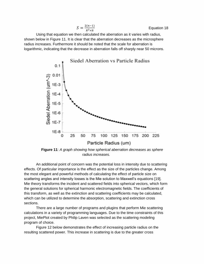
Using that equation we then calculated the aberration as it varies with radius,
shown below in Figure 11. It is clear that the aberration decreases as the microsphere
radius increases. Furthermore it should be noted that the scale for aberration is
logarithmic, indicating that the decrease in aberration falls off sharply near 50 microns.
Figure 11: A graph showing how spherical aberration decreases as sphere
radius increases.
An additional point of concern was the potential loss in intensity due to scattering
effects. Of particular importance is the effect as the size of the particles change. Among
the most elegant and powerful methods of calculating the effect of particle size on
scattering angles and intensity losses is the Mie solution to Maxwell’s equations [19].
Mie theory transforms the incident and scattered fields into spherical vectors, which form
the general solutions for spherical harmonic electromagnetic fields. The coefficients of
this transform, as well as the extinction and scattering coefficients may be calculated,
which can be utilized to determine the absorption, scattering and extinction cross
sections.
There are a large number of programs and plugins that perform Mie scattering
calculations in a variety of programming languages. Due to the time constraints of this
project, MiePlot created by Philip Laven was selected as the scattering modeling
program of choice.
Figure 12 below demonstrates the effect of increasing particle radius on the
resulting scattered power. This increase in scattering is due to the greater cross
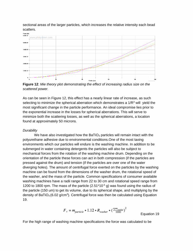
sectional areas of the larger particles, which increases the relative intensity each bead
scatters.
Figure 12: Mie theory plot demonstrating the effect of increasing radius size on the
scattered power.
As can be seen in Figure 12, this effect has a nearly linear rate of increase, as such
selecting to minimize the spherical aberration which demonstrates a 1/R3 will yield the
most significant change in the particle performance. An ideal compromise lies prior to
the exponential increase in the losses for spherical aberrations. This will serve to
minimize both the scattering losses, as well as the spherical aberrations, a location
found at approximately 50 microns.
Durability
We have also investigated how the BaTiO3 particles will remain intact with the
polyurethane adhesive due to environmental conditions.One of the most taxing
environments which our particles will endure is the washing machine. In addition to be
submerged in water containing detergents the particles will also be subject to
mechanical forces from the rotation of the washing machine drum. Depending on the
orientation of the particle these forces can act in both compression (if the particles are
pressed against the drum) and tension (if the particles are over one of the water
diverging holes). The amount of centrifugal force exerted on the particles by the washing
machine can be found from the dimensions of the washer drum, the rotational speed of
the washer, and the mass of the particle. Common specifications of consumer available
washing machines have a radii range from 22 to 30 cm and rotational speed range from
1200 to 1800 rpm. The mass of the particle (2.51*10-5 g) was found using the radius of
the particle (150 um) to get its volume, due to its spherical shape, and multiplying by the
density of BaTiO3 (6.02 g/cm3). Centrifugal force was then be calculated using Equation
19.
Equation 19
For the high range of washing machine specifications the force was calculated to be
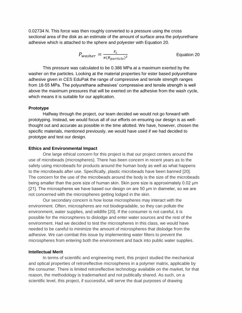
0.02734 N. This force was then roughly converted to a pressure using the cross
sectional area of the disk as an estimate of the amount of surface area the polyurethane
adhesive which is attached to the sphere and polyester with Equation 20.
𝑃𝑤𝑎𝑠ℎ𝑒𝑟 =𝐹𝑐
𝜋(𝑅𝑝𝑎𝑟𝑡𝑖𝑐𝑙𝑒)2 Equation 20
This pressure was calculated to be 0.386 MPa at a maximum exerted by the
washer on the particles. Looking at the material properties for ester based polyurethane
adhesive given in CES EduPak the range of compressive and tensile strength ranges
from 18-55 MPa. The polyurethane adhesives’ compressive and tensile strength is well
above the maximum pressures that will be exerted on the adhesive from the wash cycle,
which means it is suitable for our application.
Prototype
Halfway through the project, our team decided we would not go forward with
prototyping. Instead, we would focus all of our efforts on ensuring our design is as well-
thought out and accurate as possible in the time allotted. We have, however, chosen the
specific materials, mentioned previously, we would have used if we had decided to
prototype and test our design.
Ethics and Environmental Impact
One large ethical concern for this project is that our project centers around the
use of microbeads (microspheres). There has been concern in recent years as to the
safety using microbeads for products around the human body as well as what happens
to the microbeads after use. Specifically, plastic microbeads have been banned [20].
The concern for the use of the microbeads around the body is the size of the microbeads
being smaller than the pore size of human skin. Skin pore size is approximately 0.02 μm
[21]. The microspheres we have based our design on are 50 μm in diameter, so we are
not concerned with the microspheres getting lodged in the skin.
Our secondary concern is how loose microspheres may interact with the
environment. Often, microspheres are not biodegradable, so they can pollute the
environment, water supplies, and wildlife [20]. If the consumer is not careful, it is
possible for the microspheres to dislodge and enter water sources and the rest of the
environment. Had we decided to test the microspheres in this class, we would have
needed to be careful to minimize the amount of microspheres that dislodge from the
adhesive. We can combat this issue by implementing water filters to prevent the
microspheres from entering both the environment and back into public water supplies.
Intellectual Merit
In terms of scientific and engineering merit, this project studied the mechanical
and optical properties of retroreflective microspheres in a polymer matrix, applicable by
the consumer. There is limited retroreflective technology available on the market, for that
reason, the methodology is trademarked and not publically shared. As such, on a
scientific level, this project, if successful, will serve the dual purposes of drawing
attention to the state of retroreflective research in order to generate interest and promote
future projects.
In the initial stages of the project, the group gathered information for material
selection through networking with professionals in addition to researching and modeling
of the optical properties of BaTiO3 and the adhesive properties of the polyurethane.
Gaining knowledge of modeling techniques will be beneficial in pursuit of further
academic and industrial goals where modeling is an increasingly useful tool with the
continual increase in computer power. Finally, the group acquired skills in experimental
design.
Broader Impact
By far the largest impact that our design can offer is the improved safety of
pedestrians. The goal of our project is to design a product that makes pedestrians more
visible by drivers from a further distance during low-light conditions. This would allow
pedestrians to travel safer at night, especially in areas where there may not be roadside
lighting, in areas lacking sidewalks, or if the clothing makes it difficult for the pedestrian
to be seen. By making pedestrians more visible they in effect become safer, and
consequently this design has a positive impact on society. Our project idea is also
unique in that the microsphere assembly is intended to be inconspicuous and consumer-
applicable. If fabrication of our design was successful, this would introduce new
potentials in retroreflective fabric technology.
Results and Discussion
Our results are completely based on our design calculations and modelling.
Although we did not prototype, we have decided on the specific materials we would have
used. Based upon the materials described earlier in this paper, we have checked that
the properties are compatible with each other. Our design process relied heavily on
computational analysis. We have finalized the manufacturing and application processes,
portrayed previously in Figure 2. In our specific case, the angle of divergence necessary
for retroreflection to be a success was calculated to be 0.697 degrees. Using ray tracing
techniques, we proved that BaTiO3 with an index of refraction of 1.93 is the best choice
because it gives angles of reflectance closest to the optimal angle of reflection at a
stopping distance of 344 feet. Using Fresnel coefficients, we calculated the reflectance
at each incident angle. We studied chromatic aberration and found that the index of
refraction decreases as the wavelength of light increases. With regards to spherical
aberration, we found that as the radius increases, the aberration decreases, and that the
optimal radius is 50 μm due to the dramatic drop of. Mie scattering increases as the
microsphere radius increases. Our optimal radius based on spherical aberration, 50 μm,
occurs before the relationship becomes exponential, indicating that our chosen radius
remains valid. We performed durability calculations and found that the polyurethane
adhesive tensile and compressive strength exceed those which will be induced on it
during normal wear and tear. We chose polyurethane to bind the microspheres to the
polyester for its temperature and adhesion properties. As a way to keep the
microspheres oriented for retroreflection throughout the application process, we used a
polyimide adhesive film due to its weak adhesion properties.
Conclusions
Throughout the course of this project, our thought process shifted. The designs
at the beginning and end of the course are significantly different from each other. As we
gained more knowledge on both the materials and processes that would allow us to
create a successful design, we found better options. At one point, we were considering
using silane to increase the adhesion of the polyurethane, but we soon realized this was
unnecessary after networking in the department. We set out to design a retroreflecting
adhesive in order for a driver to see a pedestrian, based off of our angle of divergence
calculations, this would be possible. We calculated that the reflectance for different
incident angles and saw that the reflectance varies with angle, however, light will always
be coming in at multiple angles and hitting many microspheres so this still allows for
retroreflectivity to work in the manner with which we aimed for.
The materials we chose to use in our design include some of the same materials
that are currently used in retroreflecting fabrics. Coated glass microspheres, like our
choice of aluminum coated BaTiO3, are a well-known retroreflecting material. Current
products available tend to be pressure sensitive adhesives, whereas ours is a hot-melt
adhesive. In addition to the adhesive properties possible using a polyurethane hot-melt,
we chose this type application in hopes that this method would give a more natural look
to the clothing since the microspheres would essentially be implanted into the pores in
the polyester fabric. The pressure sensitive tapes on the other hand sit on top of the
fabric.
Future Work
Had this project been completed over a longer period of time, our team would
have gone through with prototyping experiments and testing. Our prototyping would
have started by fabricating our design. Tests would have been carried out on the product
to test its retroreflective properties, namely the retroreflecting intensity in ambient light
versus headlight conditions. Once we were satisfied with the performance, we would
have assembled the product the way we intend our consumers to do so. Additional tests
would have been completed to ensure the assembly process did not affect the
retroreflectivity of the tape. Finally, we would have tested the durability and lifetime
integrity of the tape while attached to clothing. Our original plan for prototyping only
included designing and testing for the tape to be attached to polyester, although if given
more time we would test other fabrics as well.
If we were to move forward, we have a clear path for future work. We would first
need to find a better method of connecting all our ray tracing and aberration calculations
to find the optimal radius. We would need to factor in intensities, which we had
previously not done. We also should do our ray tracing at multiple wavelengths to
represent the different colors of visible light. We would also look further into chromatic
aberration and search for data about an index of refraction of 1.93 specifically or try to
experimentally fit the Sellmeier Equation to 1.93 ourselves. After we completed the
project, we were made aware of some potential problems. One of them being that would
we would need to consider the likelihood of our temporary polyimide adhesive will leave
a residue. Since at this point in the process, the customer would be in possession of the
product, we would need to find a simple and safe way for them to remove this residue.
We would begin by physically prototyping the design to allow us to optimize the
fabrication procedure. Testing of the selected polyurethane hot melt adhesive will allow
us to confirm the reported properties, which will allow us to tune the fabrication process
to maximize product quality. Further testing of the optical properties will ensure the
retroreflective properties are maintained following the fabrication process. We will also
begin application and durability testing of the tape to determine user experience,
durability on additional types of clothing, product lifetime and degradation mechanisms.
Acknowledgements
We would like to thank Dr. Raymond Phaneuf for his guidance and support
throughout the duration of this course as well as his assistance with the ray tracing
modeling. We would also like to thank Drew Stasak’s QUEST business project
colleagues, specifically QUEST Professor J. Gerald Suarez, as well as teammates Laura
Bell, Robert Crumbaugh, Donald Rutigliano, and Linda Yau. We would like to credit the
original idea of a general reflective material to Donald Rutigliano. We would like to thank
Dr. Robert Briber with his assistance with polymer properties and, for the brief time we
considered its use, his help with silane properties. Finally, we would like to thank
Christopher Wong for his advice on the use of silane.
References
[1] Traffic Safety Facts 2013 Data—Pedestrians. National Highway Traffic Safety Administration, National Center for Statistics and Analysis, 2013. [2] Lloyd, John. “A Brief History of Retroreflective Sign Face Sheet Materials.” Understanding Retroreflectivity. 2008. [3] Charles, Edwin Searight, Mclaurin Alexander Ezra, and Robert Ryan John. "High titanate glass beads." U.S. Patent No. 3,293,051. 20 Dec. 1966.
[4] O’Bannon, Loran. “Dictionary of Ceramic Science and Engineering.” New York: Plenum Press, 1983.
[5] GLUETEX. Technical Data Sheet UKF 438. Klettgau-Erzingen: GLUETEX, 2015.
[6] Leverette, Mary. "Are You Using The Right Iron Temperature?" About.com. About
Home, 15 Dec. 2015.
[7] 3M Electronics Materials Solutions Division, 3M™ Polyimide Film Tape 5413, Saint
Paul, Minnesota, 3M, 2014
[8] Huelke, Donald F. “An Overview of Anatomical Considerations of Infants and Children in the Adult World of Automobile Safety Design.” Association for the Advancement of Automotive Medicine. 42 (1998) 93-113.
[9] United States of America. Virginia General Assembly. Code of Virginia.
[10] Center for Disease Control and Prevention. “Anthropometric Reference Data for Children and Adults: United States, 2007-2010.” Vital and Health Statistics, 11.252 (2012).
[11] Budnik, Eric A., Carol C.Flannagan, Michael J. Flannagan, Shinichi Kojima, Michael Sivak. “The Locations of Headlamps and Driver Eye Positions in Vehicles in the U.S.A.” University of Michigan Transportation Research Institute. Nov 1996.
[12] Grabowski, Jurek G., Bethany D. Koetje. “A Methodology for the Geometric Standardization of Vehicle Hoods to Compare Real-World Pedestrian Crashes.” Association for the Advancement of Automotive Crashes. 52 (2008) 193-198.
[13] Koehler, Kenneth R. “Spectral Sensitivity of the Eye.” College Physics for Students of Biology and Chemistry. 1996.
[14] Nave, R. “Rod Details.” Hyperphysics.
[15] Alexander I. Lvovsky . Fresnel Equations. In Encyclopedia of Optical Engineering. Taylor and Francis: New York, Published online: 27 Feb 2013; 1-6.
[16] Leng, Y. Materials Characterization : Introduction to Microscopic and Spectroscopic Methods. Second edition. Weinheim, Germany: Wiley-VCH, 2013. 7.Print.
[17] Setzler, S. D., et al. "Periodically Poled Barium Titanate as a New Nonlinear Optical Material." Advanced Solid State Lasers. Optical Society of America, 1999.
[18] Sacek, Vladimir. "Aberration Function." Aberration Function. N.p., 14 July 2006.
[19] García-Cámara, B ‘ON LIGHT SCATTERING BY NANOPARTICLES WITH CONVENTIONAL AND NON-CONVENTIONAL OPTICAL PROPERTIES’ Diss. Universidad de Cantabria, 2010.
[20] Legislators Call on FDA to Study use of Plastic Microbeads in Toothpastes. Regulatory Affairs Professionals Society, 2014.
[21] Aguilella, Vicente, Kyösti Kontturi, Lasse Murtomäki, and Patricio Ramírez.
"Estimation of the Pore Size and Charge Density in Human Cadaver Skin." Journal of
Controlled Release 32.3 (1994): 249-57.
Recommended