Compressed air preparationCompressed air storage
Moisture management
Catalog #1
Loca
l dis
trib
utor
Comprag GmbH
Wilhelm- Muthmann- Strasse 1542329 Wuppertal, GermanyTel.: +49- (0)202- 747015- 0Fax: +49- (0)202- 747015- 25Web: www.comprag.com

This Catalogue is valid from May 2015.All previous catalogues lose their validity with the publication of the new catalogue.Technical characteristics, specifications and details published in this catalogue are subject to change without notice.Comprag GmbH.
The latest catalogue version is available for download on our web pagewww.comprag.com
Copyright © 2015 Comprag GmbH. All rights reserved.
3
Compressed air preparation, Compressed air storage, Moisture managementCatalog #1
Features:
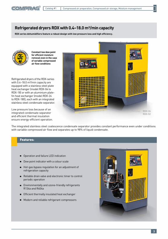
Refrigerated dryers RDX with 0.4–18.0 m³/min capacityRDX series dehumidifiers feature a robust design with low pressure loss and high efficiency.
Refrigerated dryers of the RDX-series with 0.4–18.0 m³/min capacity are equipped with a stainless steel plate heat exchanger (model RDX-04 to RDX-18) or with an aluminium plate-fin heat exchanger (model RDX-24 to RDX-180), each with an integrated stainless steel condensate separator.
Low pressure loss because of an integrated condensate separator and efficient thermal insulation ensure energy-efficient operation.
The integrated stainless steel coalescence condensate separator provides constant performance even under conditions with variable compressed air flow and separates up to 98% of liquid condensate.
Operation and failure LED indication
Dew point indicator with a colour scale
Hot-gas bypass regulation for an adjustment of refrigeration capacity
Reliable drain valve and electronic timer to control periodic operation
Environmentally and ozone-friendly refrigerants R134a and R404a
Efficient thermally insulated heat exchanger
Modern and reliable refrigerant compressors
Pictured: RDX-24 RDX-52
Constant low dew point for efficient moisture removal even in the case of variable compressed air flow conditions
4
Compressed air preparation, Compressed air storage, Moisture managementCatalog #1
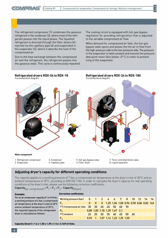
The refrigerant compressor (1) condenses the gaseous refrigerant in the condenser (3), where most of the refri-gerant passes into the liquid phase. The liquefied refrigerant is directed through the filter-dryers (6), injected via the capillary pipe (4) and evaporated in the evaporator (2), where it absorbs the heat of the compressed air.
Due to the heat exchange between the compressed air and the refrigerant, the refrigerant passes into the gaseous state. This cycle is continuously repeated.
The cooling circuit is equipped with hot-gas bypass regulation for providing refrigeration that is adjusted to the variable compressed air flow.
When demand for compressed air falls, the hot-gas bypass valve opens and allows the hot air to flow from the high-pressure side to the low-pressure side. The pressure in the evaporator is held constant and ensures the pressure dew point never falls below +3° C in order to prevent icing of the evaporator.
87
7
6
6
5
5
4
4
3
3
1
1
2 2
Refrigerated dryers RDX-04 to RDX-18Functional block diagram
Refrigerated dryers RDX-24 to RDX-180Functional block diagram
Correction coefficients:
Working pressure (bar) 0 1 2 4 6 7 8 10 12 14 16F1 X X X 1,25 1,06 1,00 0,96 0,90 0,86 0,82 0,8T°C Compressed air inlet 30 35 40 45 50 60 70F2 0,85 1,00 1,18 1,39 1,67 2,1T°C Ambient 22 25 30 35 40 45 50 60F3 0,92 1 1,07 1,14 1,22 1,35 1,50
The capacity applies to a working pressure of 7 bar, a compressed air temperature at the dryer’s inlet of 35°C and an ambient temperature of 25°C, according to DIN ISO 7183. In order to calculate the dryer’s capacity for real operating conditions at the dryer’s inlet, please use the following correction coefficients:Capacity(air compressor) х F1 х F2 х F3 = Capacity(dryer).
Adjusting dryer’s capacity for different operating conditions
Main component
1. Refrigerant compressor2. Evaporator
3. Condenser4. Capillary pipe
5. Hot-gas bypass valve6. Filter-dryer
7. Time-controlled drain valve8. Liquid separator
Example:For an air compressor capacity of 1.6 m³/min, a working pressure of 4 bar, a compressed air temperature at the dryer’s inlet of 45°C and an ambient temperature of 35°C, the required capacity of the refrigerated dryer is calculated as follows:
Capacity (dryer) = 1.6 x 1.25 x 1.39 x 1.14 = 3.169 m³/min.
5
Compressed air preparation, Compressed air storage, Moisture managementCatalog #1
Art
icle
Mod
el
Air
flow
*(m
³/m
in)
Max
. wor
king
pr
essu
re(b
ar)
Scre
w
conn
ectio
n
Rat
ed v
olta
ge(P
hase
/V/H
z)
Driv
e po
wer
(kW
)
14310000 RDX-04 0,40 16 G 1/2” 1/230/50 0,1
14310001 RDX-06 0,60 16 G 1/2” 1/230/50 0,2
14310002 RDX-09 0,90 16 G 1/2” 1/230/50 0,2
14310003 RDX-12 1,20 16 G 1/2” 1/230/50 0,3
14310004 RDX-18 1,80 16 G 1/2” 1/230/50 0,3
14310005 RDX-24 2,40 14 G 1” 1/230/50 0,5
14310006 RDX-30 3,00 14 G 1” 1/230/50 0,6
14310007 RDX-36 3,60 14 G 1” 1/230/50 0,7
14310008 RDX 41 4,10 14 G 1” 1/230/50 0,8
14310009 RDX-52 5,20 14 G 1 1/2” 1/230/50 1,0
14310010 RDX-65 6,50 14 G 1 1/2” 1/230/50 1,1
14310011 RDX-77 7,70 14 G 1 1/2” 1/230/50 1,5
14310012 RDX-100 10,00 14 G 2 1/2” 3/380/50 2,1
14310013 RDX-120 12,00 14 G 2 1/2” 3/380/50 2,2
14310014 RDX-150 15,00 14 G 2 1/2” 3/380/50 2,4
14310015 RDX-180 18,00 14 G 2 1/2” 3/380/50 3,0
*Measured according to ISO 7183
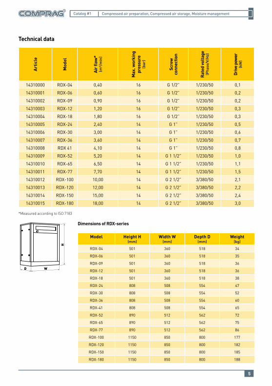
Technical data
Dimensions of RDX-series
H
WD
Model Height H(mm)
Width W(mm)
Depth D(mm)
Weight(kg)
RDX-04 501 360 518 34
RDX-06 501 360 518 35
RDX-09 501 360 518 36
RDX-12 501 360 518 36
RDX-18 501 360 518 38
RDX-24 808 508 554 47
RDX-30 808 508 554 52
RDX-36 808 508 554 60
RDX-41 808 508 554 65
RDX-52 890 512 562 72
RDX-65 890 512 562 75
RDX-77 890 512 562 86
RDX-100 1150 850 800 177
RDX-120 1150 850 800 182
RDX-150 1150 850 800 185
RDX-180 1150 850 800 188
6
Compressed air preparation, Compressed air storage, Moisture managementCatalog #1
Purg
e ai
r (%
)
Optimum cycle time
Switching cycle (min.)
Optimum cycle timeOptimum cycle time
Comprag ADXadsorption dryer
Optimum cycle time of 10 minutes
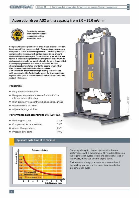
Adsorption dryer ADX with a capacity from 2.0 – 25.0 m³/min
Comprag adsorption dryers operate at optimum performance with a cycle time of 10 minutes. Reducing the regeneration cycles lowers the operational load of the towers, the valves and the drying agent.
Furthermore, a long cycle reduces pressure loss if the working pressure in the tower is restored after a regeneration cycle.
Properties:
Fully automatic operation
Dew point at constant pressure from -40 °C for efficient dehumidification
High-grade drying agent with high specific surface
Optimum cycle of 10 min.
Adjustable purge air flow
Performance data according to DIN ISO 7183:
Working pressure:
Compressed air temperature:
Ambient temperature:
Pressure dew point:
7 bar
35°C
25°C
-40°C
Comprag ADX adsorption dryers are a highly efficient solution for dehumidifying compressed air. They can keep the pressure dew point at -40 °C at constant pressure. The adsorption dryer comprises two towers, which contain the optimum amountof dehumidifying drying agent. Compressed air is fed into the two towers in an alternating manner and brought into contact with the drying agent at a moderate speed, whereby the air is dehumidified. If the drying agent of the first tower is too moist, the flow of compressed air switches over to the second tower, which then takes on the function of moisture uptake.ADX adsorption dryers feature high-quality control valves with long service life. Switching between the drying cycle and regeneration cycle is controlled electronically with a switching cycle of 10 minutes.
Pict
ured
: AD
X-16
0
Consistently low dew point also with variable compressed air flow from 0% to 100%.
7
Compressed air preparation, Compressed air storage, Moisture managementCatalog #1
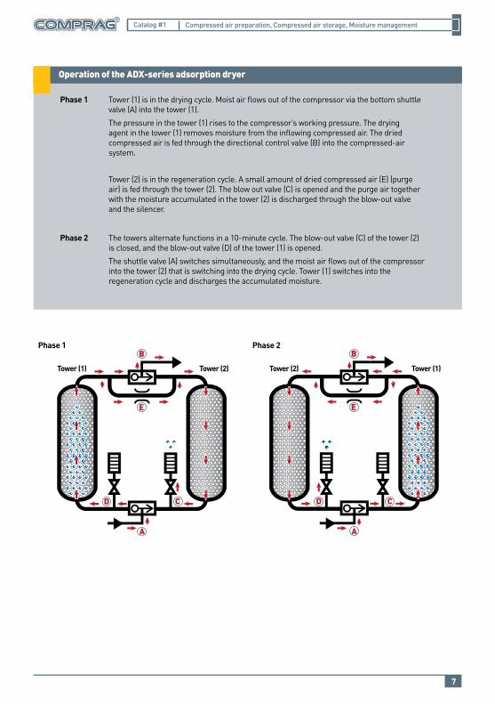
Operation of the ADX-series adsorption dryer
Tower (1) Tower (2) Tower (1)Tower (2)
Phase 1 Phase 2
Tower (1) is in the drying cycle. Moist air flows out of the compressor via the bottom shuttle valve (A) into the tower (1).
The pressure in the tower (1) rises to the compressor’s working pressure. The drying agent in the tower (1) removes moisture from the inflowing compressed air. The dried compressed air is fed through the directional control valve (B) into the compressed-air system.
Tower (2) is in the regeneration cycle. A small amount of dried compressed air (E) (purge air) is fed through the tower (2). The blow out valve (C) is opened and the purge air together with the moisture accumulated in the tower (2) is discharged through the blow-out valve and the silencer.
The towers alternate functions in a 10-minute cycle. The blow-out valve (C) of the tower (2) is closed, and the blow-out valve (D) of the tower (1) is opened.
The shuttle valve (A) switches simultaneously, and the moist air flows out of the compressor into the tower (2) that is switching into the drying cycle. Tower (1) switches into the regeneration cycle and discharges the accumulated moisture.
Phase 1
Phase 2
8
Compressed air preparation, Compressed air storage, Moisture managementCatalog #1
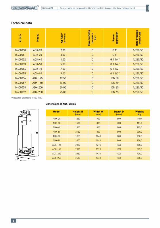
Dimensions of ADX-series
D W
H
Model Height H(mm)
Width W(mm)
Depth D(mm)
Weight(kg)
ADX-20 1220 800 600 90,0
ADX-30 1500 800 600 111,0
ADX-40 1850 800 800 175,0
ADX-50 2130 800 800 200,0
ADX-70 1950 1040 800 250,0
ADX-90 2200 1040 800 300,0
ADX-125 2320 1275 1000 500,0
ADX-160 2320 1320 1000 565,0
ADX-200 2320 1430 1000 720,0
ADX-250 2630 1430 1000 800,0
Art
icle
Mod
el
Air
flow
*(m
³/m
in)
Max
. wor
king
pr
essu
re(b
ar)
Scre
w
conn
ectio
n
Rat
ed v
olta
ge(P
hase
/V/H
z)
14400050 ADX-20 2,00 10 G 1” 1/230/50
14400051 ADX-30 3,00 10 G 1” 1/230/50
14400052 ADX-40 4,00 10 G 1 1/4” 1/230/50
14400053 ADX-50 5,00 10 G 1 1/4” 1/230/50
14400054 ADX-70 7,00 10 G 1 1/2” 1/230/50
14400055 ADX-90 9,00 10 G 1 1/2” 1/230/50
14400056 ADX-125 12,50 10 DN 50 1/230/50
14400057 ADX-160 16,00 10 DN 50 1/230/50
14400058 ADX-200 20,00 10 DN 65 1/230/50
14400059 ADX-250 25,00 10 DN 65 1/230/50
*Measured according to ISO 7183
Technical data
9
Compressed air preparation, Compressed air storage, Moisture managementCatalog #1
SV safery valves
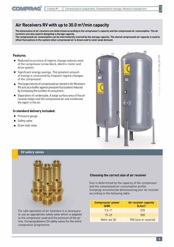
Air Receivers RV with up to 30.0 m³/min capacity
FeaturesReduced occurrence of regime change reduces wear of the compressor screw block, electric motor and drive system.
Significant energy savings. The greatest amount of energy is consumed by frequent regime changes of the compressor.
The large volume of compressed air stored in Air Receivers RV acts as a buffer against pressure fluctuations induced by increasing the number of consumers.
Separation of condensate. A large surface area of the air receiver helps cool the compressed air and condenses the vapor in the air.
In standard delivery included:Pressure gauge
Safety valve
Drain ball valve
Pict
ured
.: Ai
r re
ceiv
ers
RV-
500,
RV-
900
The dimensions of air receivers are determined according to the compressor’s capacity and the compressed air consumption. The air receivers are also used in designing a storage capacity.The compressed-air consumption can be intermittently covered by the storage capacity. The stored compressed-air capacity is used to offset fluctuations in the system when compressed air is drawn and to cover peak demand.
For safe operation of air receivers it is necessary to use an appropriate safety valve which is adapted to the compressor used and the pressure of the air line. Comprag delivers SV safety valves for the entire compressor programme.
Choosing the correct size of air receiver
Size is determined by the capacity of the compressor and the compressed air consumption profile. Comprag recommends dimensioning your air receiver according to the following table:
Compressor power (kW)
Air receiver capacity(Liter)
7,5-11 270
15-22 500
Mehr als 30 900 (one or several)
10
Compressed air preparation, Compressed air storage, Moisture managementCatalog #1
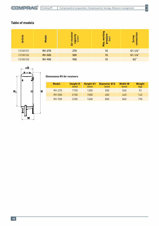
Table of modelsA
rtic
le
Mod
el
Air
rec
eive
r ca
paci
ty
(Lite
r)
Max
. wor
king
pr
essu
re(b
ar)
Scre
wco
nnec
tion
13100101 RV-270 270 10 G1.1/4“
13100102 RV-500 500 10 G1.1/4“
13100103 RV-900 900 10 G2“
D
W
HH1
Dimensions RV Air receivers
Model Height H(mm)
Height H1(mm)
Diameter Ø D (mm)
Width W (mm)
Weight(kg)
RV-270 1730 1200 500 540 92
RV-500 2100 1500 600 640 142
RV-900 2200 1400 800 840 190
Advantages:
11
Compressed air preparation, Compressed air storage, Moisture managementCatalog #1
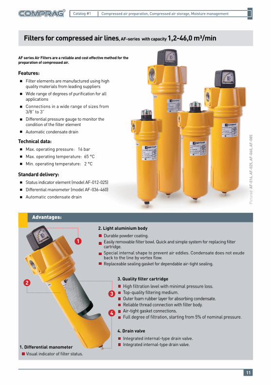
Filters for compressed air lines, AF-series with capacity 1,2-46,0 m³/min
Features:Filter elements are manufactured using high quality materials from leading suppliers
Wide range of degrees of purification for all applications
Connections in a wide range of sizes from 3/8” to 3”
Differential pressure gauge to monitor the condition of the filter element
Automatic condensate drain
Technical data:Max. operating pressure: 16 bar
Max. operating temperature: 65 °C
Min. operating temperature: 2 °C
Standard delivery:Status indicator element (model AF-012-025)
Differential manometer (model AF-036-460)
Automatic condensate drain
Pict
ured
AF-
016,
AF-
025,
AF-
060,
AF-
085
AF series Air Filters are a reliable and cost effective method for the preparation of compressed air.
4
3
1
23. Quality filter cartridge
High filtration level with minimal pressure loss.Top-quality filtering medium.Outer foam rubber layer for absorbing condensate.Reliable thread connection with filter body.Air-tight gasket connections.Full degree of filtration, starting from 5% of nominal pressure.
2. Light aluminium body
Durable powder coating.Easily removable filter bowl. Quick and simple system for replacing filter cartridge.Special internal shape to prevent air eddies. Condensate does not exude back to the line by vortex flow.Replaceable sealing gasket for dependable air-tight sealing.
4. Drain valve
Integrated internal-type drain valve.Integrated internal-type drain valve.1. Differential manometer
Visual indicator of filter status.
12
Compressed air preparation, Compressed air storage, Moisture managementCatalog #1
Filter elements for AF-series
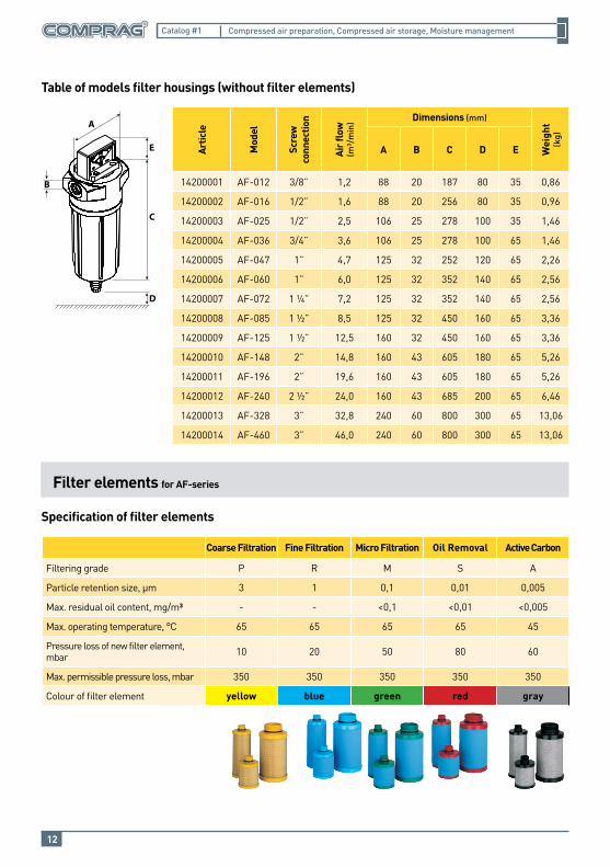
Table of models filter housings (without filter elements)
Artic
le
Mod
el
Scre
wco
nnec
tion
Air
flow
(m³/
min
) Dimensions (mm)
Wei
ght
(kg)
А B C D E
14200001 AF-012 3/8” 1,2 88 20 187 80 35 0,86
14200002 AF-016 1/2” 1,6 88 20 256 80 35 0,96
14200003 AF-025 1/2” 2,5 106 25 278 100 35 1,46
14200004 AF-036 3/4” 3,6 106 25 278 100 65 1,46
14200005 AF-047 1” 4,7 125 32 252 120 65 2,26
14200006 AF-060 1” 6,0 125 32 352 140 65 2,56
14200007 AF-072 1 ¼” 7,2 125 32 352 140 65 2,56
14200008 AF-085 1 ½” 8,5 125 32 450 160 65 3,36
14200009 AF-125 1 ½” 12,5 160 32 450 160 65 3,36
14200010 AF-148 2” 14,8 160 43 605 180 65 5,26
14200011 AF-196 2” 19,6 160 43 605 180 65 5,26
14200012 AF-240 2 ½” 24,0 160 43 685 200 65 6,46
14200013 AF-328 3” 32,8 240 60 800 300 65 13,06
14200014 AF-460 3” 46,0 240 60 800 300 65 13,06
Specification of filter elements
Coarse Filtration Fine Filtration Micro Filtration Oil Removal Active Carbon
Filtering grade P R M S A
Particle retention size, µm 3 1 0,1 0,01 0,005
Max. residual oil content, mg/m³ - - <0,1 <0,01 <0,005
Max. operating temperature, °C 65 65 65 65 45
Pressure loss of new filter element, mbar 10 20 50 80 60
Max. permissible pressure loss, mbar 350 350 350 350 350
Colour of filter element yellow blue green red gray
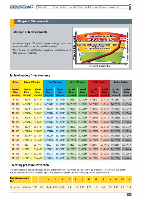
Life span of filter elements
13
Compressed air preparation, Compressed air storage, Moisture managementCatalog #1
Operating pressure correction
Table of models filter elements
Grade Coarse Filtration Fine Filtration Micro Filtration Oil Removal Active Carbon
Model filter
housing
ArticleFilter
element
Model filter
element
ArticleFilter
element
Model filter
element
ArticleFilter
element
Model filter
element
ArticleFilter
element
Model filter
element
ArticleFilter
element
Model filter
element
AF-012 14222101 EL-012P 14222201 EL-012R 14222301 EL-012M 14222401 EL-012S 14222501 EL-012A
AF-016 14222102 EL-016P 14222202 EL-016R 14222302 EL-016M 14222402 EL-016S 14222502 EL-016A
AF-025 14222103 EL-025P 14222203 EL-025R 14222303 EL-025M 14222403 EL-025S 14222503 EL-025A
AF-036 14222104 EL-036P 14222204 EL-036R 14222304 EL-036M 14222404 EL-036S 14222504 EL-036A
AF-047 14222105 EL-047P 14222205 EL-047R 14222305 EL-047M 14222405 EL-047S 14222505 EL-047A
AF-060 14222106 EL-060P 14222206 EL-060R 14222306 EL-060M 14222406 EL-060S 14222506 EL-060A
AF-072 14222107 EL-072P 14222207 EL-072R 14222307 EL-072M 14222407 EL-072S 14222507 EL-072A
AF-085 14222108 EL-085P 14222208 EL-085R 14222308 EL-085M 14222408 EL-085S 14222508 EL-085A
AF-125 14222109 EL-125P 14222209 EL-125R 14222309 EL-125M 14222409 EL-125S 14222509 EL-125A
AF-148 14222110 EL-148P 14222210 EL-148R 14222310 EL-148M 14222410 EL-148S 14222510 EL-148A
AF-196 14222111 EL-196P 14222211 EL-196R 14222311 EL-196M 14222411 EL-196S 14222511 EL-196A
AF-240 14222112 EL-240P 14222212 EL-240R 14222312 EL-240M 14222412 EL-240S 14222512 EL-240A
AF-328 14222113 EL-328P 14222213 EL-328R 14222313 EL-328M 14222413 EL-328S 14222513 EL-328A
AF-460 14222114 EL-460P 14222214 EL-460R 14222314 EL-460M 14222414 EL-460S 14222514 EL-460A
Life span of filter elements
A pressure drop of 400 mbar increases energy costs com-mensurate with the cost of a new filter element.
When the pressure is 700 mbar (maximum) a replacement of filter element is required.
The above table is designed based on the performance of the filters at 7 bar working pressure. To calculate the perfor-mance of the filter with a different operating pressure, please use the following correcting coefficients:
Pre
ssur
e dr
op (
mba
r)
700700
Cos
ts r
epla
cem
ent e
lem
ent
Element service-life
Filterelement should bereplace immediatel
Filterelement should bereplace immediatel
Energy costs caused by pressure loss are equal to costs
of replacement elemens Energy costs caused by pressure loss
are equal to costsof replacement elemens
Operating pressure, bar 2 3 4 5 6 7 8 9 10 11 12 13 14 15 16
Correction coefficient 0,38 0,5 0,63 0,75 0,88 1,0 1,13 1,25 1,38 1,5 1,63 1,75 1,88 2,0 2,13
Advantages:
14
Compressed air preparation, Compressed air storage, Moisture managementCatalog #1
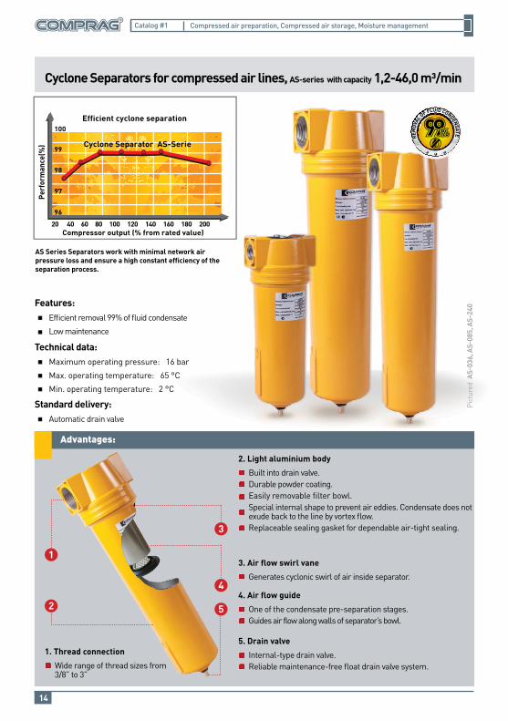
Cyclone Separators for compressed air lines, AS-series with capacity 1,2-46,0 m³/min
Features:Efficient removal 99% of fluid condensate
Low maintenance
Technical data:Maximum operating pressure: 16 bar
Max. operating temperature: 65 °C
Min. operating temperature: 2 °C
Standard delivery:Automatic drain valve
Pict
ured
AS-
036,
AS-
085,
AS-
240
AS Series Separators work with minimal network air pressure loss and ensure a high constant efficiency of the separation process.
5
4
3
1
2
3. Air flow swirl vane
Generates cyclonic swirl of air inside separator.
2. Light aluminium body
Built into drain valve.Durable powder coating.Easily removable filter bowl.Special internal shape to prevent air eddies. Condensate does not exude back to the line by vortex flow.Replaceable sealing gasket for dependable air-tight sealing.
5. Drain valve
Internal-type drain valve.Reliable maintenance-free float drain valve system.
4. Air flow guide
One of the condensate pre-separation stages.Guides air flow along walls of separator’s bowl.
1. Thread connection
Wide range of thread sizes from 3/8” to 3”
REM
OVAL
OF FLUID CONDENSATE
Perf
orm
ance
(%)
Efficient cyclone separation
Compressor output (% from rated value)
Cyclone Separator AS-Serie
Level of filtration for any fields of application
15
Compressed air preparation, Compressed air storage, Moisture managementCatalog #1
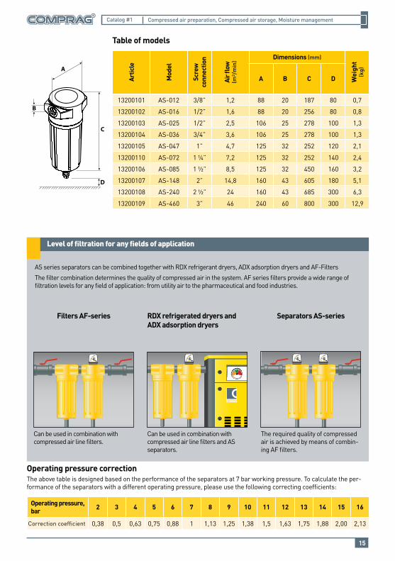
AS series separators can be combined together with RDX refrigerant dryers, ADX adsorption dryers and AF-Filters
The filter combination determines the quality of compressed air in the system. AF series filters provide a wide range of filtration levels for any field of application: from utility air to the pharmaceutical and food industries.
Filters AF-series RDX refrigerated dryers and ADX adsorption dryers
Separators AS-series
Can be used in combination with compressed air line filters.
Can be used in combination with compressed air line filters and AS separators.
The required quality of compressed air is achieved by means of combin-ing AF filters.
Operating pressure correctionThe above table is designed based on the performance of the separators at 7 bar working pressure. To calculate the per-formance of the separators with a different operating pressure, please use the following correcting coefficients:
Artic
le
Mod
el
Scre
wco
nnec
tion
Air fl
ow
(m³/
min
) Dimensions (mm)
Wei
ght
(kg)
A B C D
13200101 AS-012 3/8” 1,2 88 20 187 80 0,7
13200102 AS-016 1/2” 1,6 88 20 256 80 0,8
13200103 AS-025 1/2” 2,5 106 25 278 100 1,3
13200104 AS-036 3/4” 3,6 106 25 278 100 1,3
13200105 AS-047 1” 4,7 125 32 252 120 2,1
13200110 AS-072 1 ¼” 7,2 125 32 252 140 2,4
13200106 AS-085 1 ½” 8,5 125 32 450 160 3,2
13200107 AS-148 2” 14,8 160 43 605 180 5,1
13200108 AS-240 2 ½” 24 160 43 685 300 6,3
13200109 AS-460 3” 46 240 60 800 300 12,9
Table of models
Operating pressure, bar 2 3 4 5 6 7 8 9 10 11 12 13 14 15 16
Correction coefficient 0,38 0,5 0,63 0,75 0,88 1 1,13 1,25 1,38 1,5 1,63 1,75 1,88 2,00 2,13
Features
16
Compressed air preparation, Compressed air storage, Moisture managementCatalog #1
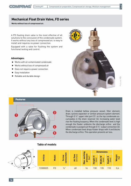
Drain is installed bellow pressure vessel, filter element, dryer, cyclone separator or similar pressure system element. Through G ½” upper inlet port (1) on the top condensate ac-cumulates in the drain reservoir (4). Increasing water level rise the floating buoyancy. When the condensate level is high enough the floater unblocks the discharge orifice and the condensate is purged out through G ½” output connection (2). When condensate level drops floater drops with it and blocks the discharge orifice. This operation prevents air loss.
Table of models
Mechanical Float Drain Valve, FD series Works without loss of compressed air.
A FD floating drain valve is the most effective of all solutions to the conclusion of the condensate system. It works without any loss of compressed air, is easy to install and requires no power connection.
Equipped with a valve for flushing the system and functional testing and control.
Advantages:Works with oil contaminated condensate
Works without loss of compressed air
Does not require a power connection
Easy installation
Reliable and durable design
Pict
ured
FD
Art
icle
Mod
el
Scre
w
conn
ectio
n
Air
flow
(m³/
min
)
Max
. wor
king
pr
essu
re(b
ar)
Dimensions
Wei
ght
(kg)
Hei
ght H
(mm
)
Wid
th W
(mm
)
Dep
th D
(mm
)
13300025 FD ½” 60 16 130 135 110 0,6
H
W
D
5
4
31
2
17
Compressed air preparation, Compressed air storage, Moisture managementCatalog #1
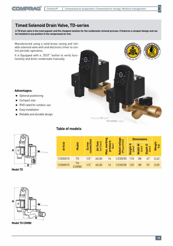
Timed Solenoid Drain Valve, TD-series A TD drain valve is the most popular and the cheapest solution for the condensate removal process. It features a compact design and can be installed in any position in the compressed air line.
Manufactured using a solid brass casing and reli-able solenoid valve with and electronic timer to con-trol periodic operation.
It is Equipped with a „TEST“ button to verify func-tionality and drain condensate manually.
Advantages:Optional positioning
Compact size
IP65 rated for outdoor use
Easy installation
Reliable and durable designPictured TD (left), TD COMBI (right)
Table of models
Model TD
Model TD COMBI
H W
D
Art
icle
Mod
el
Scre
w
conn
ectio
n
Air
flow
(m³/
min
)
Max
. wor
king
pr
essu
re(b
ar)
Rat
ed v
olta
ge(P
hase
/V/H
z) Dimensions
Wei
ght
(kg)
Hei
ght H
(mm
)
Wid
th W
(mm
)
Dep
th D
(mm
)
13300010 TD 1/2” 60,00 16 1/230/50 110 88 47 0,42
13300015 TDCOMBI 1/2” 60,00 16 1/230/50 125 88 92 0,55
HW
D
Why are separators for process condensate needed?
18
Compressed air preparation, Compressed air storage, Moisture managementCatalog #1
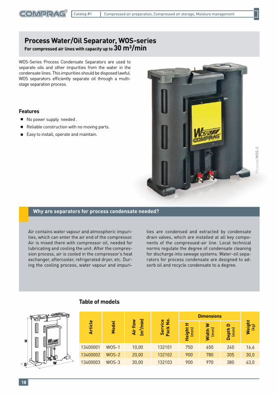
Process Water/Oil Separator, WOS-seriesFor compressed air lines with capacity up to 30 m³/min
FeaturesNo power supply needed .
Reliable construction with no moving parts.
Easy to install, operate and maintain.
WOS-Series Process Condensate Separators are used to separate oils and other impurities from the water in the condensate lines. This impurities should be disposed lawful.WOS separators efficiently separate oil through a multi-stage separation process.
Air contains water vapour and atmospheric impuri-ties, which can enter the air end of the compressor. Air is mixed there with compressor oil, needed for lubricating and cooling the unit. After the compres-sion process, air is cooled in the compressor’s heat exchanger, aftercooler, refrigerated dryer, etc. Dur-ing the cooling process, water vapour and impuri-
ties are condensed and extracted by condensate drain valves, which are installed at all key compo-nents of the compressed-air line. Local technical norms regulate the degree of condensate cleaning for discharge into sewage systems. Water-oil sepa-rators for process condensate are designed to ad-sorb oil and recycle condensate to a degree.
Pict
ured
WOS
-2
Table of models
H
WD
Art
icle
Mod
el
Air
flow
(m³ /
min
)
Serv
ice
Pack
No.
Dimensions
Wei
ght
(kg)
Hei
ght H
(mm
)
Wid
th W
(mm
)
Dep
th D
(mm
)
13400001 WOS-1 10,00 132101 750 650 240 16,6
13400002 WOS-2 20,00 132102 900 780 305 30,0
13400003 WOS-3 30,00 132103 900 970 380 43,0

© 2015 COMPRAG GMBH.Аll rights reversed.
Loca
l dis
trib
utor
Comprag GmbH
Wilhelm- Muthmann- Strasse 1542329 Wuppertal, GermanyTel.: +49- (0)202- 747015- 0Fax: +49- (0)202- 747015- 25Web: www.comprag.com
Compressed air preparationCompressed air storage
Moisture management
Catalog #1
Recommended