8/10/2019 COLORADO - Torsiunea Barelor Cu Pereti Subtiri 1
http://slidepdf.com/reader/full/colorado-torsiunea-barelor-cu-pereti-subtiri-1 1/11
8Torsion of Open Thin Wall
(OTW) Sections
8–1
8/10/2019 COLORADO - Torsiunea Barelor Cu Pereti Subtiri 1
http://slidepdf.com/reader/full/colorado-torsiunea-barelor-cu-pereti-subtiri-1 2/11
Lecture 8: TORSION OF OPEN THIN WALL (OTW) SECTIONS
TABLE OF CONTENTS
Page
§8.1 Introduction . . . . . . . . . . . . . . . . . . . . . 8–3
§8.2 TW Section Classification . . . . . . . . . . . . . . . . 8–3
§8.3 Open TW Sections: Rectangle . . . . . . . . . . . . . . . 8–4
§8.3.1 Behavior of Torqued Member with Solid Rectangular Cross Section 8–5
§8.3.2 Stress and Twist-Rate Formulas for Rectangle . . . . . . 8–5
§8.4 Rectifiable OTW Sections . . . . . . . . . . . . . . . . 8–6
§8.5 Torsion of a T Profile . . . . . . . . . . . . . . . . . . 8–7
§8.6 A Z Profile with Variable Wall Thickness . . . . . . . . . . 8–8
§8.7 OTW Torsion Examples . . . . . . . . . . . . . . . . . 8–9
§8.7.1 A Double T Steel Beam . . . . . . . . . . . . . 8–9
§8.8 General Decomposition of an OTW Section . . . . . . . . . . 8–10
8–2
8/10/2019 COLORADO - Torsiunea Barelor Cu Pereti Subtiri 1
http://slidepdf.com/reader/full/colorado-torsiunea-barelor-cu-pereti-subtiri-1 3/11
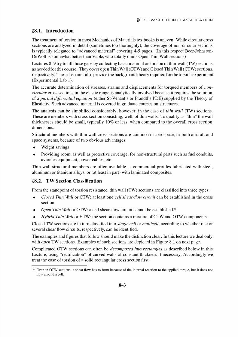
§8.2 TW SECTION CLASSIFICATION
§8.1. Introduction
The treatment of torsion in most Mechanics of Materials textbooks is uneven. While circular cross
sections are analyzed in detail (sometimes too thoroughly), the coverage of non-circular sections
is typically relegated to “advanced material” covering 4-5 pages. (In this respect Beer-Johnston-
DeWolf is somewhat better than Vable, who totally omits Open Thin Wall sections)
Lectures 8–9 try to fill those gaps by collecting basic material on torsion of thin-wall (TW) sections
as needed for this course. Theycover open Thin Wall (OTW) and Closed Thin Wall (CTW) sections,
respectively. These Lectures also provide thebackground theory required for the torsion experiment
(Experimental Lab 1).
The accurate determination of stresses, strains and displacements for torqued members of non-
circular cross sections in the elastic range is analytically involved because it requires the solution
of a partial differential equation (either St-Venant’s or Prandtl’s PDE) supplied by the Theory of
Elasticity. Such advanced material is covered in graduate courses on structures.
The analysis can be simplified considerably, however, in the case of thin wall (TW) sections.
These are members with cross section consisting, well, of thin walls. To qualify as “thin” the wallthicknesses should be small, typically 10% or less, when compared to the overall cross section
dimensions.
Structural members with thin wall cross sections are common in aerospace, in both aircraft and
space systems, because of two obvious advantages:
• Weight savings
• Providing room, as well as protective coverage, for non-structural parts such as fuel conduits,
avionics equipment, power cables, etc
Thin-wall structural members are often available as commercial profiles fabricated with steel,
aluminum or titanium alloys, or (at least in part) with laminated composites.
§8.2. TW Section Classification
From the standpoint of torsion resistance, thin wall (TW) sections are classified into three types:
• Closed Thin Wall or CTW: at least one cell shear-flow circuit can be established in the cross
section.
• Open Thin Wall or OTW: a cell shear-flow circuit cannot be established.*
• Hybrid Thin Wall or HTW: the section contains a mixture of CTW and OTW components.
Closed TW sections are in turn classified into single cell or multicell, according to whether one or
several shear flow circuits, respectively, can be identified.
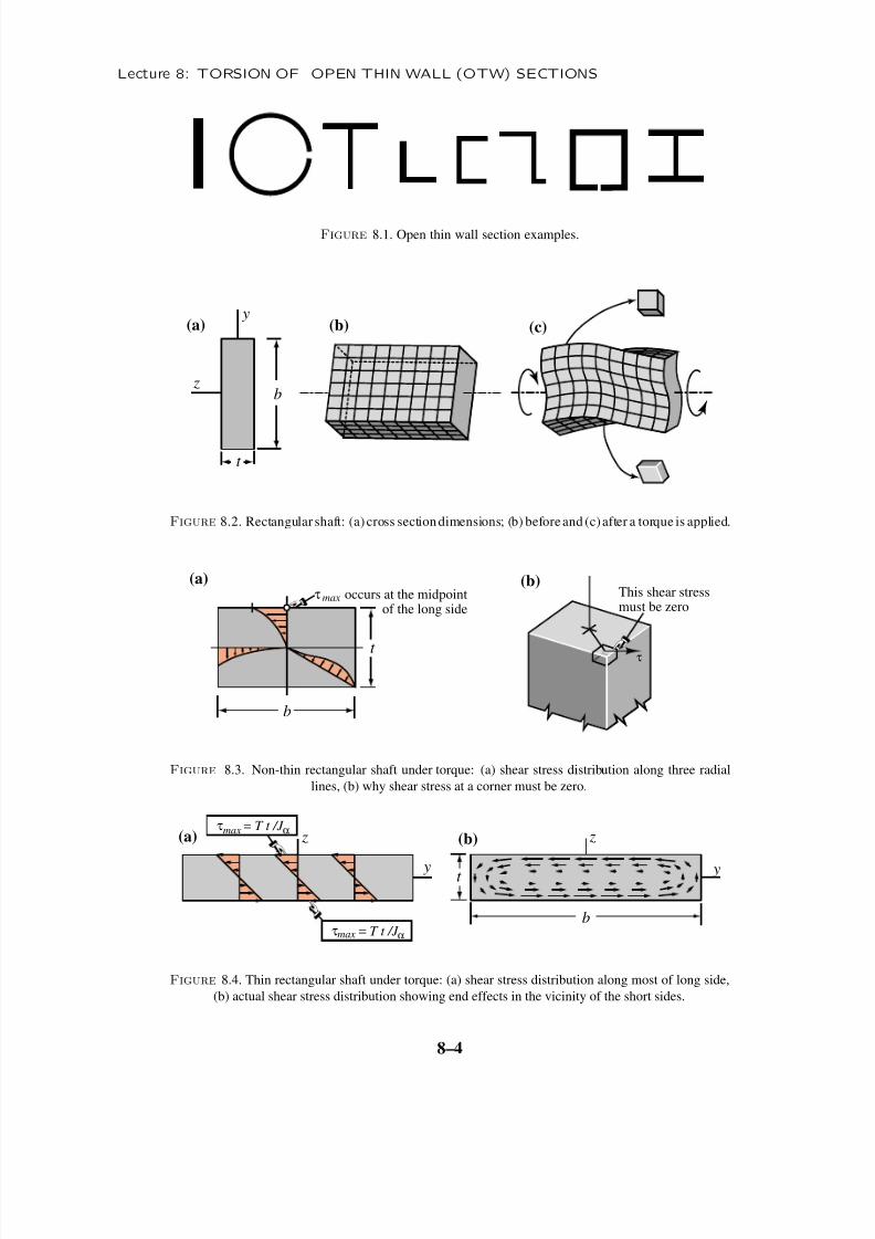
The examples and figures that follow should make the distinction clear. In this lecture we deal onlywith open TW sections. Examples of such sections are depicted in Figure 8.1 on next page.
Complicated OTW sections can often be decomposed into rectangles as described below in this
Lecture, using “rectification” of curved walls of constant thickness if necessary. Accordingly we
treat the case of torsion of a solid rectangular cross section first.
* Even in OTW sections, a shear flow has to form because of the internal reaction to the applied torque, but it does not
flow around a cell.
8–3
8/10/2019 COLORADO - Torsiunea Barelor Cu Pereti Subtiri 1
http://slidepdf.com/reader/full/colorado-torsiunea-barelor-cu-pereti-subtiri-1 4/11
Lecture 8: TORSION OF OPEN THIN WALL (OTW) SECTIONS
Figure 8.1. Open thin wall section examples.
(c)(a) (b)
z
y
b
t
Figure 8.2. Rectangular shaft: (a) cross sectiondimensions; (b) beforeand (c)after a torque is applied.
τ
(a) (b)
b
t
τ occurs at the midpoint of the long side
max This shear stressmust be zero
Figure 8.3. Non-thin rectangular shaft under torque: (a) shear stress distribution along three radial
lines, (b) why shear stress at a corner must be zero.
(a)
y y
z zτ = T t /J
αmax
τ = T t /J αmax
(b)
t
b
Figure 8.4. Thin rectangular shaft under torque: (a) shear stress distribution along most of long side,
(b) actual shear stress distribution showing end effects in the vicinity of the short sides.
8–4
8/10/2019 COLORADO - Torsiunea Barelor Cu Pereti Subtiri 1
http://slidepdf.com/reader/full/colorado-torsiunea-barelor-cu-pereti-subtiri-1 5/11
§8.3 OPEN TW SECTIONS: RECTANGLE
§8.3. Open TW Sections: Rectangle
This section covers the rectangular cross section in some detail. This provides a “divide and
conquer” tool for the treatment of more general open TW sections, since (as noted) those can be
often decomposed into rectangles.
§8.3.1. Behavior of Torqued Member with Solid Rectangular Cross Section
Consider a shaft with a rectangular cross section such as that shown in Figure 8.2(a). The long
dimension b is oriented along y . The short dimension t is called the thickness, which is oriented
along z. (The section pictured here is not that of a thin rectangle, because behavior visualization is
easier if b and t are of comparable magnitude.)
The untorqued shaft is pictured in Figure 8.2(b). Upon applying a torque, it deforms as sketched in
Figure 8.2(c). Figure 8.3(a) shows the shear stress distribution along three radial lines emanating
from the center. Two important differences with the case of circular cross section shaft studied in
Lecture 7 are:
• Cross sections do not remain plane but warp. The nature of the distortions can be surmisedfrom Figure 8.2(c). This is actually the case for any non-circular cross section.
• In a shaft of circular cross section, the maximum shear stress occurs at all points located at
the greatest distance from the center. In a rectangle the maximum occurs at the midpoint of
the long sides, as indicated in Figure 8.3(a). At the 4 rectangle corners, which are the points
located at the greatest distance from the center, shear stresses vanish. The reason is obvious
on studying Figure 8.3(b): if the shown τ is nonzero there would be a reciprocal shear stress
acting along the surface of the shaft, which is impossible since that surface is load-free.
The rectangle is called narrow or thin if t is much smaller than b in the sense that
t ≤ b/10 or b/t ≥ 10 (8.1)
If (8.1) holds, the only important shear stress component in the x , y, z system is τ x y . This stress
varies approximately as a linear function of z. That means that it is zero at z = 0 (the rectangle
long midline) and is maximum on both surfaces z = ±t /2. It is also approximately constant along
the long rectangle dimension except in the vicinity of the edges y = ±b/2, where it drops. See
Figure 8.4(b).
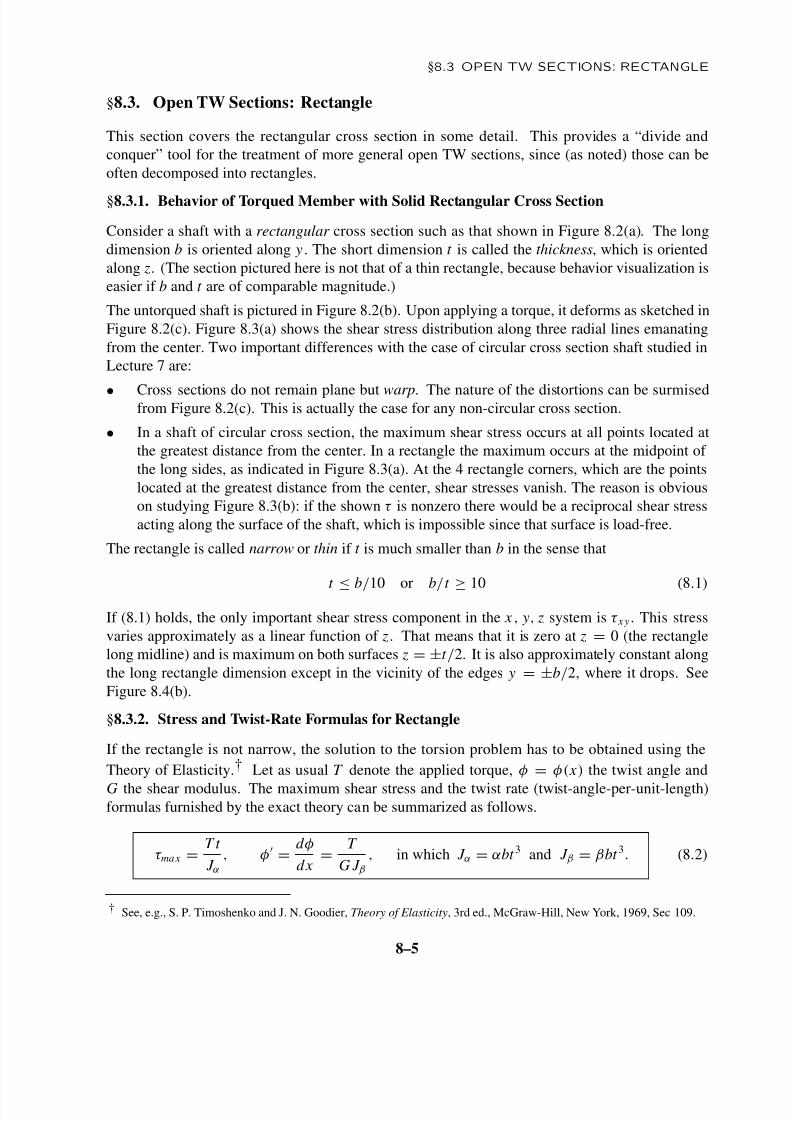
§8.3.2. Stress and Twist-Rate Formulas for Rectangle
If the rectangle is not narrow, the solution to the torsion problem has to be obtained using the
Theory of Elasticity.† Let as usual T denote the applied torque, φ = φ( x) the twist angle and
G the shear modulus. The maximum shear stress and the twist rate (twist-angle-per-unit-length)formulas furnished by the exact theory can be summarized as follows.
τ max =T t
J α, φ
=d φ
dx=
T
G J β, in which J α = αbt 3 and J β = βbt 3. (8.2)
† See, e.g., S. P. Timoshenko and J. N. Goodier, Theory of Elasticity, 3rd ed., McGraw-Hill, New York, 1969, Sec 109.
8–5
8/10/2019 COLORADO - Torsiunea Barelor Cu Pereti Subtiri 1
http://slidepdf.com/reader/full/colorado-torsiunea-barelor-cu-pereti-subtiri-1 6/11
Lecture 8: TORSION OF OPEN THIN WALL (OTW) SECTIONS
in which a prime denotes derivative with respect to x . Here α and β are numerical coef ficients that
depend on the ratio b/t , as given in the following table‡
b/t 1.0 1.2 1.5 2.0 2.5 3.0 4.0 5.0 6.0 10.0 ∞
α 0.208 0.219 0.231 0.246 0.258 0.267 0.282 0.291 0.299 0.312 1/3
β 0.141 0.166 0.196 0.229 0.249 0.263 0.281 0.291 0.299 0.312 1/3 (8.3)
For b/t ≥ 3, the two coef ficients agree to at least 2 places, and may be linearly interpolated in t /b
as
α = β ≈1
3− 0.210
t
b, (8.4)
More accurate interpolations given in Roark ’s manual† are
α = 13
1
1 + 0.6095 t b
+ 0.8865
t b
2
− 1.8025
t b
3
+ 0.9100
t b
4,
β =1
3− 0.210
t
b
1 −
1
12
t
b
4
,
(8.5)
These fit the data in (8.3) to at least 3 places for all aspect ratios b/t ≥ 1.
If the rectangle qualifies as narrow in the sense (8.1), one can adopt the easier to remember but
rougher approximation
α = β ≈ 13
, whence J = J α = J β ≈ 13 bt 3, (8.6)
This has error < 7% if b/t > 10. Such discrepancy is easily covered with safety factors. In
particular, the approximation (8.6) is suf ficient for the theory portion of Lab 1.
The torsional constant J that appears in (8.3) and (8.6) is not the polar moment of inertia
A ρ2 d A
as was the case for the circular cross sections covered in Lecture 7.* But it has the same physical
dimensions: length to the fourth power. As in the case of circular sections, the product G J that
appears in the expression of φ = d φ/dx = T /(G J ) is called the torsional rigidity. We shall use
the symbol J consistently for that purpose.
As previouly noted, the maximum shear occurs at the boundary points ( y =
0, z = ±
t /2) closestto the rectangle center. For narrow rectangles that value is approximately the same over the long
side surfaces z = ±t /2 except in the vicinity of the short sides; cf. Figure 8.4.
‡ From E. P. Popov, Engineering Mechanics of Solids, Prentice Hall, 1999, p. 243.
† W. C. Young, Roark ’s Formulas for Stress & Strain, McGraw-Hill, 6th ed., 1989, p. 348.
* It can be shown that J is always less than the polar moment of inertia except for circular cross sections. The proof of
this property, however, require mathematical knowledge beyond that assumed for this course.
8–6
8/10/2019 COLORADO - Torsiunea Barelor Cu Pereti Subtiri 1
http://slidepdf.com/reader/full/colorado-torsiunea-barelor-cu-pereti-subtiri-1 7/11
§8.5 TORSION OF A T PROFILE
b z
y
t
t
Rb
thin longitudinal cut
(a) (b)
z
y
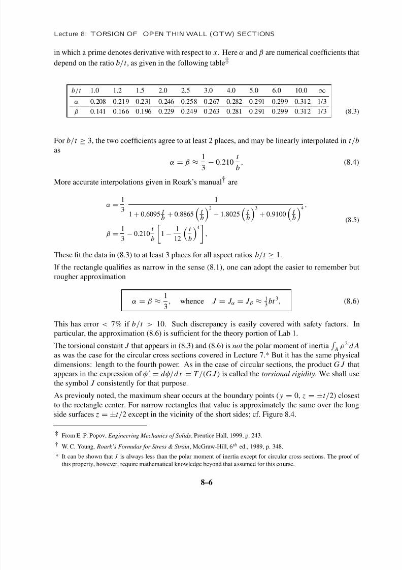
Figure 8.5. Narrowrectangleandslotted tube (cut-along) tube sections canbe treated by thesamemethod.
§8.4. Rectifiable OTW Sections
The solution (8.2)–(8.6) applies to any open TW profile than can be “rectified” into a narrow
rectangle. For example, the tube shown in Figure 8.5(b) has a thin longitudinal cut that makes itan open TW section. That solution can be used applies if one takes b = 2π R, where R is the
mid-radius; this of course assumes that the cut is of negligible width and that b/t ≥ 10.
If the rectangle isnot suf ficiently narrowtheequivalenceshouldbe used with caution, andabandoned
all together is b/t is less than, say, 2. But many shaft profiles do satisfy that geometric restriction.
This method can be also used for channel (C), L or Z profiles, because those can be rectified
into rectangles. This equivalence holds as long as the profile is fabricated of the same material
throughout, and has a uniform wall thickness. Else the decomposition-into-rectangles method
outlined below for the T section should be used.
The example of a Z profile with varying wall thickness is treated in §8.6. Because the thickness is
not constant, it cannot be rectified into just one rectangle.
flange
w e b
b f
t f
t wbw
=+
flange
w e b
Figure 8.6. Decomposition of a thin-wall T profile into two rectangles for torsion analysis.
§8.5. Torsion of a T Profile
Open TW profiles that cannot be rectified into a single narrow rectangle must be decomposed as
the sum of such. This is the case for T and double-T sections. The procedure is illustrated for the
T cross section pictured in Figure 8.6.
8–7
8/10/2019 COLORADO - Torsiunea Barelor Cu Pereti Subtiri 1
http://slidepdf.com/reader/full/colorado-torsiunea-barelor-cu-pereti-subtiri-1 8/11
Lecture 8: TORSION OF OPEN THIN WALL (OTW) SECTIONS
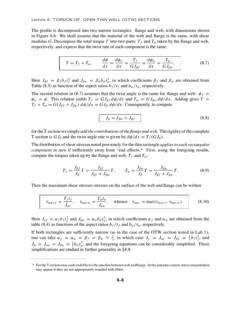
The profile is decomposed into two narrow rectangles: flange and web, with dimensions shown
in Figure 8.6. We shall assume that the material of the web and flange is the same, with shear
modulus G. Decompose the total torque T into two parts: T f and T w taken by the flange and web,
respectively, and express that the twist rate of each component is the same:
T = T f + T w,d φ
dx=
d φ f
dx=
T f
G J β f
=d φw
dx=
T w
G J βw
. (8.7)
Here J β f = β f b f t 3 f and J βw = βwbwt 3w, in which coef ficients β f and βw are obtained from
Table (8.5) as function of the aspect ratios b f /t f and bw/t w, respectively.
The second relation in (8.7) assumes that the twist angle is the same for flange and web: φ f =
φw = φ. This relation yields T f = G J β f d φ/dx and T w = G J βw d φ/dx . Adding gives T =
T f + T w = G( J β f + J βw ) d φ/dx = G J β d φ/dx . Consequently, to compute
J β = J βw + J β f (8.8)
for the T section wesimply add the contributions of the fl ange and web. The rigidity of the complete
T section is G J β and the twist angle rate is given by d φ/dx = T /(G J β ).
The distribution of shear stresses noted previously for the thin rectangle applies to each rectangular
component in turn if suf ficiently away from “end effects.* First, using the foregoing results,
compute the torques taken up by the flange and web, T f and T w:
T f = J β f
J βT =
J β f
J β f + J βw
T , T w = J βw
J βT =
J βw
J β f + J βw
T . (8.9)
Then the maximum shear stresses stresses on the surface of the web and flange can be written
τ max f =T f t f
J α f
, τ max w =T wt w
J αw
, whence τ max = max(τ max f , τ max w ). (8.10)
Here J α f = α f b f t 3 f and J αw = αwbwt 3w, in which coef ficients α f and αw are obtained from the
table (8.4) as functions of the aspect ratios b f /t f and bw/t w, respectively.
If both rectangles are suf ficiently narrow (as in the case of the OTW section tested in Lab 1),one can take α f = αw = β f = βw ≈
13, in which case J f = J α f = J β f =
13b f t
3 f , and
J w = J αw = J βw = 13bwt 3w, and the foregoing equations can be considerably simplified. These
simplifications are studied in further generality in §8.8.
* For the T section once such endeffectis the junction between web and flange. At the juncture corners stress concentration
may appear if they are not appropriately rounded with fillets.
8–8
8/10/2019 COLORADO - Torsiunea Barelor Cu Pereti Subtiri 1
http://slidepdf.com/reader/full/colorado-torsiunea-barelor-cu-pereti-subtiri-1 9/11
§8.7 OTW TORSION EXAMPLES
buf
t uf
t w
bw
=
+
+lower flange
upper flange
w e
b
t lf
blf lower flange
upper flange
w e
b
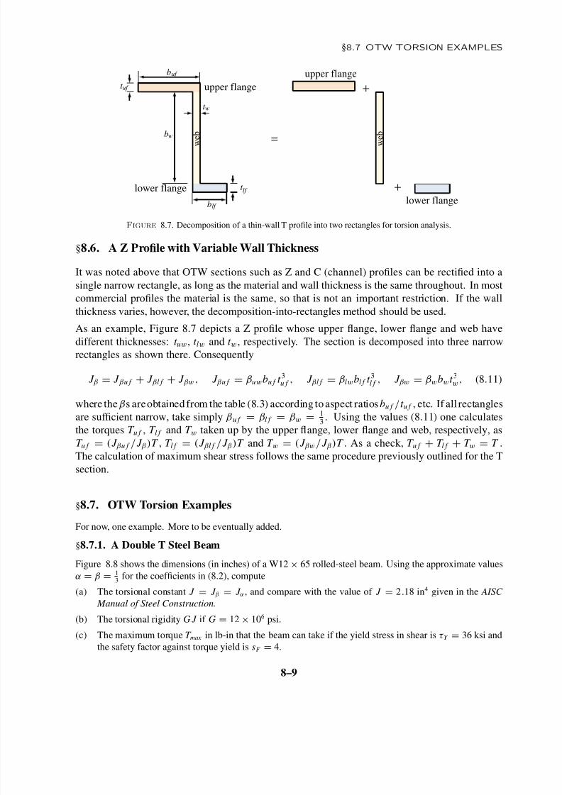
Figure 8.7. Decomposition of a thin-wall T profile into two rectangles for torsion analysis.
§8.6. A Z Profile with Variable Wall Thickness
It was noted above that OTW sections such as Z and C (channel) profiles can be rectified into a
single narrow rectangle, as long as the material and wall thickness is the same throughout. In most
commercial profiles the material is the same, so that is not an important restriction. If the wall
thickness varies, however, the decomposition-into-rectangles method should be used.
As an example, Figure 8.7 depicts a Z profile whose upper flange, lower flange and web have
different thicknesses: t uw, t lw and t w, respectively. The section is decomposed into three narrow
rectangles as shown there. Consequently
J β = J βu f + J βl f + J βw , J βu f = βuwbu f t 3u f , J βl f = βlwbl f t
3l f , J βw = βwbwt 3w, (8.11)
where the βs areobtained from the table (8.3) according toaspect ratios bu f /t u f , etc. If all rectangles
are suf ficient narrow, take simply βu f = βl f = βw = 13 . Using the values (8.11) one calculates
the torques T u f , T l f and T w taken up by the upper flange, lower flange and web, respectively, as
T u f = ( J βu f / J β )T , T l f = ( J βl f / J β )T and T w = ( J βw / J β )T . As a check, T u f + T l f + T w = T .
The calculation of maximum shear stress follows the same procedure previously outlined for the T
section.
§8.7. OTW Torsion Examples
For now, one example. More to be eventually added.
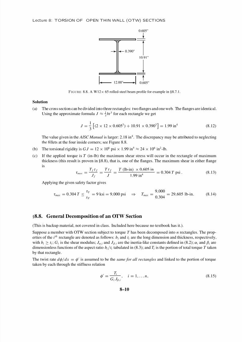
§8.7.1. A Double T Steel Beam
Figure 8.8 shows the dimensions (in inches) of a W12 × 65 rolled-steel beam. Using the approximate values
α = β = 1
3 for the coef ficients in (8.2), compute
(a) The torsional constant J = J β = J α , and compare with the value of J = 2.18 in4 given in the AISC
Manual of Steel Construction.
(b) The torsional rigidity G J if G = 12 × 106 psi.
(c) The maximum torque T max in lb-in that the beam can take if the yield stress in shear is τ Y = 36 ksi and
the safety factor against torque yield is sF = 4.
8–9
8/10/2019 COLORADO - Torsiunea Barelor Cu Pereti Subtiri 1
http://slidepdf.com/reader/full/colorado-torsiunea-barelor-cu-pereti-subtiri-1 10/11
Lecture 8: TORSION OF OPEN THIN WALL (OTW) SECTIONS
0.390"
0.605"
0.605"
10.91"
12.00"
Figure 8.8. A W12× 65 rolled-steel beam profile for example in §8.7.1.
Solution
(a) The cross section can bedivided into three rectangles: two flanges andoneweb. The flanges are identical.
Using the approximate formula J ≈ 1
3bt 3 for each rectangle we get
J =1
3
(2 × 12 × 0.6053) + 10.91 × 0.3903
= 1.99 in4 (8.12)
The value given in the AISC Manual is larger: 2.18 in4. The discrepancy may be attributed to neglecting
the fillets at the four inside corners; see Figure 8.8.
(b) The torsional rigidity is G J = 12 × 106 psi × 1.99 in4≈ 24 × 106 in2-lb.
(c) If the applied torque is T (in-lb) the maximum shear stress will occur in the rectangle of maximum
thickness (this result is proven in §8.8), that is, one of the flanges. The maximum shear in either flange
is
τ max =T f t f
J f =
T t f
J =
T (lb-in) × 0.605 in
1.99 in4 = 0.304 T psi . (8.13)
Applying the given safety factor gives
τ max = 0.304 T ≤τ Y
sF
= 9 ksi = 9,000 psi ⇒ T max =9,000
0.304= 29,605 lb-in. (8.14)
§8.8. General Decomposition of an OTW Section
(This is backup material, not covered in class. Included here because no textbook has it.).
Suppose a member with OTW section subject to torque T has been decomposed into n rectangles. The prop-
erties of the i th rectangle are denoted as follows: bi and t
i are the long dimension and thickness, respectively,
with bi ≥ t i ; G i is the shear modulus; J α,i and J β,i are the inertia-like constants defined in (8.2); αi and βi are
dimensionless functions of the aspect ratio bi /t i tabulated in (8.3); and T i is the portion of total torque T taken
by that rectangle.
The twist rate d φ/dx = φ is assumed to be the same for all rectangles and linked to the portion of torque
taken by each through the stiffness relation
φ=
T i
Gi J β,i
, i = 1, . . . n, (8.15)
8–10
8/10/2019 COLORADO - Torsiunea Barelor Cu Pereti Subtiri 1
http://slidepdf.com/reader/full/colorado-torsiunea-barelor-cu-pereti-subtiri-1 11/11
§8.8 GENERAL DECOMPOSITION OF AN OTW SECTION
Assumption (8.15) provides n − 1 independent equations, which in addition to the equilibrium condition
T =
ni=1
T i (8.16)
gives n equations for the n unknowns T i . The quickest way to solve this system is as follows. Express
T i = Gi J β,i φ from (8.15), replace into (8.16), factor out the twist rate and solve for it:
T =
ni=1
Gi J β,i
φ def
= (G J β ) φ⇒ φ
=T
G J β(8.17)
in which G J β =n
i=1 Gi J β,i is the total torsional rigidity of the member. Consequently the torque portions
are given explicitly as the rigidity ratios
T i =Gi J β,i
G J βT , i = 1, . . . n. (8.18)
(Note that it is impossible to separate G from G J β unless the shear modulus is the same for all rectangles, acommon case considered below.) The maximum shear stress in the i th rectangle is τ max ,i = T i t i / J α,i and the
overall maximum is
τ max = maxi
(τ max ,i ) = maxi
T i t i
J α,i
, i = 1, . . . n. (8.19)
Several simplifications are worth noting. First, if all rectangles are made of the same material so that Gi = G
for all i , the shear modulus cancels out in (8.18), which reduces to
T i = J β,i
J βT , i = 1, . . . n, in which J β =
ni=1
J β,i (8.20)
Next, if all rectangles are so narrow that we can take α = β = 1
3, then J
β,i = J
α,i = J
i =
1
3b
i t 3
i , whence α
and β may be dropped from the J subscripts. The total J is simply J =n
i=1 J i and
T i = J i
J T , τ max = max
i
T i t i
J i
= max
i
T t i
J
=
T
J max
it i , i = 1, . . . n. (8.21)
The last form of τ max says that the largest shear stress will occur wherever the thickness is larger .
Finally, if all rectangles have the common thickness t ,
J =
ni=1
1
3bi t
3=
1
3b t 3, in which b =
ni=1
bi , (8.22)
which is the “rectification recipe:” the n rectangles may be coalesced into one with long dimension b equalto the sum of all bi . Observe that for this to be valid three conditions must hold: (a) the shear modulus must
be the same throughout, (b) all rectangles must have the same thickness, and (c) all rectangles must be so thin
than α = β ≈ 1
3.
8–11
Recommended