Cisco SCE8000 Software Configuration GuideRelease 3.1.6S February 15, 2011
Americas HeadquartersCisco Systems, Inc.170 West Tasman DriveSan Jose, CA 95134-1706 USAhttp://www.cisco.comTel: 408 526-4000
800 553-NETS (6387)Fax: 408 527-0883
Text Part Number: OL-16479-01

THE SPECIFICATIONS AND INFORMATION REGARDING THE PRODUCTS IN THIS MANUAL ARE SUBJECT TO CHANGE WITHOUT NOTICE. ALL STATEMENTS, INFORMATION, AND RECOMMENDATIONS IN THIS MANUAL ARE BELIEVED TO BE ACCURATE BUT ARE PRESENTED WITHOUT WARRANTY OF ANY KIND, EXPRESS OR IMPLIED. USERS MUST TAKE FULL RESPONSIBILITY FOR THEIR APPLICATION OF ANY PRODUCTS.
THE SOFTWARE LICENSE AND LIMITED WARRANTY FOR THE ACCOMPANYING PRODUCT ARE SET FORTH IN THE INFORMATION PACKET THAT SHIPPED WITH THE PRODUCT AND ARE INCORPORATED HEREIN BY THIS REFERENCE. IF YOU ARE UNABLE TO LOCATE THE SOFTWARE LICENSE OR LIMITED WARRANTY, CONTACT YOUR CISCO REPRESENTATIVE FOR A COPY.
The Cisco implementation of TCP header compression is an adaptation of a program developed by the University of California, Berkeley (UCB) as part of UCB’s public domain version of the UNIX operating system. All rights reserved. Copyright © 1981, Regents of the University of California.
NOTWITHSTANDING ANY OTHER WARRANTY HEREIN, ALL DOCUMENT FILES AND SOFTWARE OF THESE SUPPLIERS ARE PROVIDED “AS IS” WITH ALL FAULTS. CISCO AND THE ABOVE-NAMED SUPPLIERS DISCLAIM ALL WARRANTIES, EXPRESSED OR IMPLIED, INCLUDING, WITHOUT LIMITATION, THOSE OF MERCHANTABILITY, FITNESS FOR A PARTICULAR PURPOSE AND NONINFRINGEMENT OR ARISING FROM A COURSE OF DEALING, USAGE, OR TRADE PRACTICE.
IN NO EVENT SHALL CISCO OR ITS SUPPLIERS BE LIABLE FOR ANY INDIRECT, SPECIAL, CONSEQUENTIAL, OR INCIDENTAL DAMAGES, INCLUDING, WITHOUT LIMITATION, LOST PROFITS OR LOSS OR DAMAGE TO DATA ARISING OUT OF THE USE OR INABILITY TO USE THIS MANUAL, EVEN IF CISCO OR ITS SUPPLIERS HAVE BEEN ADVISED OF THE POSSIBILITY OF SUCH DAMAGES.
Cisco and the Cisco Logo are trademarks of Cisco Systems, Inc. and/or its affiliates in the U.S. and other countries. A listing of Cisco's trademarks can be found at www.cisco.com/go/trademarks. Third party trademarks mentioned are the property of their respective owners. The use of the word partner does not imply a partnership relationship between Cisco and any other company. (1005R)
Any Internet Protocol (IP) addresses used in this document are not intended to be actual addresses. Any examples, command display output, and figures included in the document are shown for illustrative purposes only. Any use of actual IP addresses in illustrative content is unintentional and coincidental.
Cisco SCE8000 Software Configuration Guide © 2011 Cisco Systems, Inc. All rights reserved.

OL-16479-01
C O N T E N T S
Preface xvii
Document Revision History xvii
Organization xvii
Related Publications xviii
Conventions xix
Obtaining Documentation and Submitting a Service Request xx
C H A P T E R 1 Cisco Service Control Overview 1-1
Cisco Service Control Solution 1-1
Service Control for Broadband Service Providers 1-2
Cisco Service Control Capabilities 1-2
SCE Platform Description 1-3
Management and Collection 1-4
Network Management 1-5
Subscriber Management 1-5
Service Configuration Management 1-6
Data Collection 1-6
C H A P T E R 2 Command Line Interface 2-1
Getting Help 2-1
Authorization and Command Levels (Hierarchy) 2-2
CLI Command Hierarchy 2-3
Prompt Indications 2-5
CLI Help Features 2-6
Partial Help 2-6
Argument Help 2-6
The [no] Prefix 2-7
Navigational and Shortcut Features 2-7
Command History 2-7
Keyboard Shortcuts 2-8
Tab Completion 2-9
FTP User Name and Password 2-9
Managing Command Output 2-9
iiiCisco SCE8000 Software Configuration Guide, Rel 3.1.6S

Contents
Scrolling the Screen Display 2-10
Filtering Command Output 2-10
Redirecting Command Output to a File 2-10
CLI Authorization Levels 2-11
How to change from User to Viewer level authorization 2-12
How to log in with Root level authorization 2-12
Exiting Modes 2-12
How to exit from the Privileged Exec mode and revert to the Viewer mode 2-13
How to exit from the Global Configuration Mode 2-13
Navigating Between Configuration Modes 2-13
Entering and Exiting Global Configuration Mode 2-13
How to enter the Global Configuration Mode 2-13
How to exit the Global Configuration Mode 2-14
Interface Configuration Modes 2-14
Configuring the Ports 2-14
Entering Management Interface Configuration Mode 2-15
How to Enter Linecard Interface Configuration mode 2-15
Entering Line Interface Configuration Mode 2-16
How to navigate from one Interface Configuration Mode to another 2-16
The "do" Command: Executing Commands Without Exiting 2-16
Creating a CLI Script 2-17
C H A P T E R 3 Basic Cisco SCE8000 Platform Operations 3-1
Starting the Cisco SCE8000 Platform 3-1
Checking Conditions Prior to System Startup 3-1
Starting the System and Observing Initial Conditions 3-2
Final Tests 3-2
How to Verify Operational Status 3-3
How to View the User Log Counters 3-3
Managing Configurations 3-3
Viewing Configurations 3-4
How to Save or Change the Configuration Settings 3-5
Example for Saving or Changing the Configuration Settings 3-6
Restoring a Previous Configuration 3-7
Example for Restoring a Previous Configuration 3-7
How to Display the SCE Platform Version Information 3-8
Example for Displaying the SCE Platform Version Information 3-8
How to Display the SCE Platform Inventory 3-10
Examples for Displaying the SCE Platform Inventory 3-11
ivCisco SCE8000 Software Configuration Guide, Rel 3.1.6S
OL-16479-01

Contents
Displaying the SCE Platform Inventory: FRUs Only 3-11
Displaying the Complete SCE Platform Inventory 3-12
How to Display the System Uptime 3-14
Example for Displaying the System Uptime 3-14
Rebooting and Shutting Down the SCE Platform 3-14
Rebooting the SCE Platform 3-14
Examples for Rebooting the SCE Platform 3-15
How to Shut Down the SCE Platform 3-15
Examples for Shutting Down the SCE Platform 3-15
C H A P T E R 4 Utilities 4-1
Working with SCE Platform Files 4-1
Working with Directories 4-1
How to Create a Directory 4-1
How to Delete a Directory 4-2
How to Change Directories 4-2
How to Display your Working Directory 4-2
How to List the Files in a Directory 4-2
Working with Files 4-3
How to Rename a File 4-3
How to Delete a File 4-3
Copying Files 4-4
How to Display File Contents 4-5
How to Unzip a File 4-5
The User Log 4-5
The Logging System 4-5
Copying the User Log 4-6
Enabling and Disabling the User Log 4-6
Viewing the User Log Counters 4-6
Viewing the User Log 4-7
Clearing the User Log 4-7
Generating a File for Technical Support 4-7
Generating a File for Technical Support: Example 4-7
C H A P T E R 5 Configuring the Management Interface and Security 5-1
About Management Interface and Security 5-1
Configuring the Management Port 5-2
How to Enter Management Interface Configuration Mode 5-2
Configuring the Management Port Physical Parameters 5-2
vCisco SCE8000 Software Configuration Guide, Rel 3.1.6S
OL-16479-01

Contents
Setting the IP Address and Subnet Mask of the Management Interface 5-3
Options 5-3
Setting the IP Address and Subnet Mask of the Management Interface: Example 5-3
Configuring the Management Interface Speed and Duplex Parameters 5-3
Interface State Relationship to Speed and Duplex 5-4
How to Configure the Speed of the Management Interface 5-4
How to Configure the Duplex Operation of the Management Interface 5-5
How to Monitor the Management Interface 5-5
Configuring the Available Interfaces 5-6
TACACS+ Authentication, Authorization, and Accounting 5-6
Information About TACACS+ Authentication, Authorization, and Accounting 5-6
How to Configure the SCE Platform TACACS+ Client 5-9
How to Manage the User Database 5-12
Configuring AAA Login Authentication 5-16
Configuring AAA Privilege Level Authorization Methods 5-17
Configuring AAA Accounting 5-18
Monitoring TACACS+ Servers 5-19
Monitoring TACACS+ Users 5-19
Configuring Access Control Lists (ACLs) 5-19
About Access Control Lists 5-20
Options 5-20
How to Add Entries to an ACL 5-21
How to Remove an ACL 5-21
How to Enable an ACL 5-21
Managing the Telnet Interface 5-21
About the Telnet Interface 5-22
How to Prevent Telnet Access 5-22
How to Configure the Telnet Timeout 5-22
Configuring the SSH Server 5-22
The SSH Server 5-23
Key Management 5-23
Managing the SSH Server 5-23
How to Monitor the Status of the SSH Server 5-24
Enabling the SNMP Interface 5-25
How to Enable the SNMP Interface 5-25
How to Disable the SNMP Interface 5-25
Configuring and Managing the SNMP Interface 5-25
About the SNMP Interface 5-25
SNMP Protocol 5-26
Security Considerations 5-26
viCisco SCE8000 Software Configuration Guide, Rel 3.1.6S
OL-16479-01

Contents
About CLI 5-27
About MIBs 5-27
Configuration via SNMP 5-28
Configuring SNMP Community Strings 5-28
How to Define a Community String 5-28
How to Remove a Community String 5-29
How to Display the Configured Community Strings 5-29
How to Configure SNMP Notifications 5-29
About SNMP Notifications 5-29
How to Define SNMP Hosts 5-30
IP Configuration 5-33
Configuring the IP Routing Table 5-33
About the IP Routing Table 5-33
How to Configure the Default Gateway 5-34
How to Add an Entry to the IP Routing Table 5-34
How to Display the IP Routing Table 5-34
IP Advertising 5-35
Configuring IP Advertising 5-36
How to Display the Current IP Advertising Configuration 5-37
How to Configure the IP Address of the Management Interface 5-37
Options 5-37
Configuring the IP Address of the Management Interface: Example 5-37
Configuring Time Clocks and Time Zone 5-38
Displaying the System Time 5-38
Displaying the System Time: Example 5-38
Displaying the Calendar Time 5-39
Displaying the Calendar Time: Example 5-39
Setting the System Clock 5-39
Options 5-39
Setting the System Clock: Example 5-39
Setting the Calendar 5-39
Options 5-39
Setting the Calendar: Example 5-40
Setting the Time Zone 5-40
Options 5-40
Setting the Time Zone: Example 5-40
Removing the Current Time Zone Setting 5-41
Configuring Daylight Saving Time 5-41
Options 5-41
Guidelines 5-42
viiCisco SCE8000 Software Configuration Guide, Rel 3.1.6S
OL-16479-01

Contents
How to Define Recurring Daylight Saving Time Transitions 5-42
How to Define Non-Recurring Daylight Saving Time Transitions 5-43
How to Cancel the Daylight Saving Time Configuration 5-43
How to Display the Current Daylight Saving Time Configuration 5-43
Domain Name Server (DNS) Settings 5-44
Configuring DNS Lookup 5-44
How to Enable DNS Lookup 5-44
How to Disable DNS Lookup 5-44
Configuring Name Servers 5-45
Options 5-45
How to Define Domain Name Servers 5-45
How to Remove a Domain Name Server 5-45
How to Remove All Domain Name Servers 5-46
How to Add a Host to the Host Table 5-46
Options 5-46
Adding Hosts to Removing them from the Host Table: Examples 5-46
How to Display Current DNS Settings 5-46
Displaying Current DNS Settings: Example 5-46
C H A P T E R 6 Configuring the Line Interface 6-1
Line Interfaces 6-1
Flow Control and Bandwidth Considerations 6-1
Maximum Packet Size 6-1
How to Configure the Ten Gigabit Ethernet Line Interfaces 6-2
Tunneling Protocols 6-2
Selecting the Tunneling Mode 6-3
How to Configure IP Tunnels 6-4
IPinIP Tunneling 6-4
How to Configure the VLAN Environment 6-6
How to Configure the L2TP Environment 6-6
Asymmetric L2 Support 6-7
How to Display the Tunneling Configuration 6-8
Configuring Traffic Rules and Counters 6-8
Traffic Rules and Counters 6-8
What are Traffic Rules and Counters? 6-8
Traffic Rules 6-9
Traffic Counters 6-10
Configuring Traffic Counters 6-10
How to Create a Traffic Counter 6-10
viiiCisco SCE8000 Software Configuration Guide, Rel 3.1.6S
OL-16479-01

Contents
How to Delete a Traffic Counter 6-10
How to Delete all Existing Traffic Counters 6-11
Configuring Traffic Rules 6-11
How to Create a Traffic Rule 6-11
How to Delete a Traffic Rule 6-14
How to Delete all Traffic Rules 6-14
Managing Traffic Rules and Counters 6-14
How to View a Specified Traffic Rule 6-14
How to View all Traffic Rules 6-14
How to View a Specified Traffic Counter 6-15
How to View all Traffic Counters 6-15
How to Reset a Specified Traffic Counter 6-15
How to Reset all Traffic Counters 6-15
DSCP Marking 6-16
How to Display the DSCP Marking Configuration 6-16
Counting Dropped Packets 6-16
About Counting Dropped Packets 6-16
Disabling the Hardware Packet Drop 6-17
C H A P T E R 7 Configuring the Connection 7-1
Configuring the Connection Mode 7-1
Options 7-1
Configuring the Connection Mode Example 7-2
Monitoring the Connection Mode 7-2
Monitoring the Connection Mode: Example 7-3
Configuring the Link Mode 7-3
About the Link Mode 7-3
Options 7-3
External Optical Bypass 7-4
How to Activate the External Bypass 7-5
How to Deactivate the External Bypass 7-5
How to Set the External Bypass to the Default State 7-5
How to Display the State of the External Bypass 7-6
Link Failure Reflection 7-6
How to Enable Link Failure Reflection 7-6
How to Disable Link Failure Reflection 7-6
Enabling and Disabling Link Failure Reflection on All Ports 7-7
Options 7-7
How to Enable Link Failure Reflection on All Ports 7-7
ixCisco SCE8000 Software Configuration Guide, Rel 3.1.6S
OL-16479-01

Contents
How to Disable Link Failure Reflection on All Ports 7-7
Configuring Link Failure Reflection in Linecard-Aware Mode 7-8
How to Enable Linecard-Aware Mode 7-8
How to Disable Linecard-Aware Mode 7-8
Asymmetric Routing Topology 7-9
Asymmetric Routing and Other Service Control Capabilities 7-9
Enabling Asymmetric Routing 7-10
Monitoring Asymmetric Routing 7-10
Monitoring Asymmetric Routing: Example 7-10
Configuring a Forced Failure 7-11
How to Force a Virtual Failure 7-11
How to Exit from a Virtual Failure 7-11
Configuring the Failure Recovery Mode 7-11
Options 7-12
Configure the Failure Recovery Mode: Examples 7-12
Configuring the SCE Platform/SM Connection 7-12
Configuring the Behavior of the SCE Platform in Case of Failure of the SM 7-13
Options 7-13
Configuring the SM-SCE Platform Connection Timeout 7-13
Options 7-13
C H A P T E R 8 Raw Data Formatting: The RDR Formatter and NetFlow Exporting 8-1
RDR Formatter and NetFlow Exporting Support 8-1
The RDR Formatter 8-1
NetFlow 8-2
NetFlow Terminology 8-2
NetFlow Exporting Support 8-3
Data Destinations 8-3
Categories 8-4
Priority 8-5
Setting DSCP for NetFlow 8-5
Forwarding Modes 8-5
Protocol 8-6
Transport Type 8-6
Configuring Data Destinations and Categories 8-6
Configuringa Data Destination 8-6
Options 8-6
Configuring the Data Destinations: Examples 8-7
Configuring the Data Categories 8-7
xCisco SCE8000 Software Configuration Guide, Rel 3.1.6S
OL-16479-01

Contents
Configuring a Destination and Assigning Categories 8-8
Configuring the Forwarding Mode 8-12
Options 8-12
Configuring the Forwarding Mode: Example 8-12
Configuring the RDR Formatter 8-12
Options 8-12
How to Enable the RDR Formatter 8-13
How to Disable the RDR Formatter 8-13
How to Configure the Size of the RDR Formatter History Buffer 8-13
Configuring NetFlow Exporting Support 8-13
Options 8-13
How to Configure a DSCP Value for NetFlow 8-14
Options 8-14
How to Configure the Template Refresh Interval 8-14
Options 8-14
Configuring Dynamic Mapping of RDRs to Categories 8-14
Configuring Mappings 8-15
Options 8-15
How to Add a Mapping to a Category 8-15
How to Remove a Mapping from a Category 8-15
How to Restore the Default Mapping for a Specified RDR Tag 8-15
Displaying Data Destination Configuration and Statistics 8-16
How to the Display the Current RDR Formatter Configuration 8-16
Displaying the RDR Formatter Configuration: Example 8-16
How to the Display the Current RDR Formatter Statistics 8-17
Displaying the Current RDR Formatter Statistics: Example 8-17
Disabling the Linecard from Sending RDRs 8-18
C H A P T E R 9 Managing Subscribers 9-1
Information About Subscribers 9-1
What is a Subscriber? 9-1
Subscriber Modes in Service Control Solutions 9-2
Subscriber Mapping Limits 9-3
Aging Subscribers 9-3
Anonymous Groups and Subscriber Templates 9-4
Subscriber Files 9-4
Subscriber default csv file format 9-4
Subscriber anonymous groups csv file format 9-5
Importing and Export ingSubscriber Information 9-5
xiCisco SCE8000 Software Configuration Guide, Rel 3.1.6S
OL-16479-01

Contents
Options 9-6
How to Import Subscriber Information 9-6
How to Export Subscriber Information 9-6
How to Import a Subscriber Template 9-6
How to Export a Subscriber Template 9-7
Removing Subscribers and Templates 9-7
How to Remove a Specific Subscriber 9-7
Options 9-7
How to Remove All Introduced Subscribers 9-8
How to Remove a Specific Anonymous Subscriber 9-8
Options 9-8
How to Remove All Anonymous Subscriber Groups 9-8
How to Remove All Anonymous Subscribers 9-8
How to Remove All Subscriber Templates 9-9
How to Remove Subscribers by Device 9-9
How to Remove Subscribers from the SM 9-9
How to Remove Subscribers from a Specified SCMP Peer Device 9-9
Importing and Exporting Anonymous Groups 9-9
How to Import Anonymous Groups 9-10
Options 9-10
How to Export Anonymous Groups 9-10
Options 9-10
Monitoring Subscribers 9-10
How to Monitor the Subscriber Database 9-11
How to Display the Subscriber Database Counters 9-11
Clearing the Subscriber Database Counters 9-12
Displaying Subscribers 9-12
Displaying Subscribers: All Current Subscriber Names 9-13
Displaying Subscribers: By Subscriber Property or Prefix 9-13
How to Display Subscribers: By Mapping (IP Address or VLAN ID) 9-15
How to Display Subscriber Information 9-17
How to display a listing of subscriber properties 9-17
How to display complete information for a specified subscriber 9-17
How to display values of subscriber properties for a specified subscriber 9-18
How to display mappings for a specified subscriber 9-18
How to display OS counters for a specified subscriber 9-18
Displaying Anonymous Subscriber Information 9-19
How to display currently configured anonymous groups 9-19
How to display currently configured templates for anonymous groups 9-19
xiiCisco SCE8000 Software Configuration Guide, Rel 3.1.6S
OL-16479-01

Contents
How to display current configuration for a specified anonymous group 9-20
How to display subscribers in a specified anonymous group 9-20
How to display all subscribers currently in anonymous groups 9-20
How to display the number of subscribers in a specified anonymous group 9-20
How to display the total number of subscribers in all anonymous groups 9-20
Configuring Subscriber Aging 9-21
How to Enable Aging for Anonymous Group Subscribers 9-21
How to Enable Aging for Introduced Subscribers 9-21
How to Disable Aging for Anonymous Group Subscribers 9-21
How to Disable Aging for Introduced Subscribers 9-22
How to Set the Aging Timeout Period for Anonymous Group Subscribers 9-22
Options 9-22
How to Set the Aging Timeout Period for Introduced Subscribers 9-22
Options 9-22
How to Display Aging for Anonymous Group Subscribers 9-22
How to Display Aging for Introduced Subscribers 9-22
Configuring the SCE Platform/SM Connection 9-23
Options 9-23
How to Configure the Behavior of the SCE Platform in Case of Failure of the SM 9-23
How to Configure the SM-SCE Platform Connection Timeout 9-23
C H A P T E R 10 Identifying and Preventing Distributed-Denial-Of-Service Attacks 10-1
Attack Filtering and Attack Detection 10-1
Attack Filtering 10-1
Specific Attack Filtering 10-2
Attack Detection 10-3
Attack Detection Thresholds 10-4
Attack Handling 10-4
Subscriber Notification 10-5
Hardware Filtering 10-5
Configuring Attack Detectors 10-6
Enabling Specific-IP Detection 10-8
Options 10-9
How to Enable Specific-IP Detection 10-9
How to Enable Specific-IP Detection for the TCP Protocol Only for all Attack Directions 10-9
How to Enable Specific-IP Detection for the TCP Protocol for Port-based Detections Only for Dual-sided Attacks 10-9
How to Disable Specific-IP Detection for Protocols Other than TCP, UDP, and ICMP for all Attack Directions 10-10
xiiiCisco SCE8000 Software Configuration Guide, Rel 3.1.6S
OL-16479-01

Contents
How to Disable Specific-IP Detection for ICMP for Single-sided Attacks Defined by the Source IP 10-10
Configuring the Default Attack Detector 10-10
Options 10-10
How to Define the Default Action and Optionally the Default Thresholds 10-11
How to Reinstate the System Defaults for a Selected Set of Attack Types 10-12
How to Reinstate the System Defaults for All Attack Types 10-12
Specific Attack Detectors 10-12
Options 10-13
How to Enable a Specific Attack Detector and Assign it an AC 10-14
How to Define the Action and Optionally the Thresholds for a Specific Attack Detector 10-14
How to Define the Subscriber Notification Setting for a Specific Attack Detector 10-14
How to Define the SNMP Trap Setting for a Specific Attack Detector 10-14
How to Define the List of Destination Ports for TCP or UDP Protocols for a Specific Attack Detector 10-15
How to Delete User-Defined Values 10-15
How to Disable a Specific Attack Detector 10-15
How to Disable All Non-default Attack Detectors 10-15
How to Disable All Attack Detectors 10-16
Sample Attack Detector Configuration 10-16
Subscriber Notifications 10-17
Configuring the Subscriber Notification Port 10-17
Options 10-17
How to Remove the Subscriber Notification Port 10-17
Preventing and Forcing Attack Detection 10-18
Options 10-18
Preventing Attack Filtering 10-19
How to Configure a dont-filter Setting for a Specified Situation 10-19
How to Remove a dont-filter Setting from a Specified Situation 10-19
How to Remove All dont-filter Settings 10-19
Forcing Attack Filtering 10-19
How to Configure a force-filter Setting for a Specified Situation 10-20
How to Remove a force-filter Setting from a Specified Situation 10-20
How to Remove All force-filter Settings 10-20
Monitoring Attack Filtering 10-20
Monitoring Attack Filtering Using SNMP Traps 10-20
Monitoring Attack Filtering Using CLI Commands 10-22
How to display a specified attack detector configuration 10-23
How to display the default attack detector configuration 10-24
How to display all attack detector configurations 10-25
xivCisco SCE8000 Software Configuration Guide, Rel 3.1.6S
OL-16479-01

Contents
How to display filter state (enabled or disabled) 10-25
How to display configured threshold values and actions 10-25
How to display the current counters 10-27
How to display all currently handled attacks 10-27
How to display all existing force-filter settings 10-27
How to display all existing don't-filter settings 10-27
How to display the list of ports selected for subscriber notification 10-27
How to find out whether hardware attack filtering has been activated 10-28
Viewing the Attack Log 10-28
The Attack Log 10-28
How to View the Attack Log 10-29
How to Copy the Attack Log to a File 10-29
C H A P T E R 11 Managing the SCMP 11-1
About SCMP 11-1
SCMP Terminology 11-2
Deployment Scenarios 11-3
Single ISG Router with a Single SCE Platform (1xISG – 1xSCE) 11-3
Multiple ISG Routers with Multiple SCE Platforms via Load Balancing (NxISG – MxSCE) 11-4
SCMP Peer Devices 11-4
Connection Management 11-5
SCMP Subscriber Management 11-6
GUID and Subscriber ID 11-6
Configuring the SCMP 11-6
Configuring SCMP Parameters 11-6
How to Enable the SCMP 11-7
How to Disable the SCMP 11-7
How to Configure the SCMP Peer Device to Push Sessions 11-7
Configuring the SCMP Peer Device to Force Each Subscriber to Single SCE Platform 11-8
Defining the Keep-alive Interval Parameter 11-8
Defining the Reconnect Interval Parameter 11-9
Defining the Loss-of-Sync Timeout Parameter 11-9
Adding an SCMP Peer Device 11-9
How to Define an SCMP Peer Device 11-10
How to Assign the SCMP Peer Device to an Anonymous Group 11-10
Deleting Subscribers Managed by an SCMP Peer Device 11-11
Options 11-11
Deleting an SCMP Peer Device 11-11
Defining the Subscriber ID 11-11
xvCisco SCE8000 Software Configuration Guide, Rel 3.1.6S
OL-16479-01

Contents
Options 11-12
Configuring the RADIUS Client 11-12
Options 11-13
Monitoring the SCMP Environment 11-13
How to Monitor the SCMP 11-13
Options 11-13
How to display the general SCMP configuration 11-14
How to display the configuration all currently defined SCMP peer devices 11-14
How to display the configuration for a specified SCMP peer device 11-14
How to display the statistics for all SCMP peer devices 11-14
How to display the statistics for a specified SCMP peer device 11-15
Monitoring the RADIUS Client 11-15
A P P E N D I X A Cisco Service Control MIBs A-1
MIB Files A-1
Loading MIBs A-4
pcube to Cisco MIB Mapping A-4
Pcube Engage MIB (CISCO-SCA-BB-MIB) A-5
pcube to Cisco MIB Mapping: Detailed OID Mappings A-5
A P P E N D I X B Monitoring SCE Platform Utilization B-1
SCE Platform Utilization Indicators B-1
CPU Utilization B-2
Flows Capacity B-2
Subscribers Capacity B-2
Service Loss B-2
Monitoring Service Loss B-3
xviCisco SCE8000 Software Configuration Guide, Rel 3.1.6S
OL-16479-01

Preface
This preface describes who should read the Cisco SCE8000 Software Configuration Guide, how it is organized, and its document conventions.
This guide is for experienced network administrators who are responsible for configuring and maintaining the SCE platform.
Document Revision HistoryThe Document Revision History below records changes to this document.
OrganizationThis guide contains the following sections:
RevisionCisco Service Control Release and Date Change Summary
OL-16479-01 3.1.6S February 15, 2011
Updated Appendix A.
OL-16479-01 3.1.6S May 6, 2010
Republished
OL-16479-01 3.1.6S June, 2008
Created the Cisco SCE8000 Software Configuration Guide.
Section Title Description
1 Cisco Service Control Overview, page 1-1
Overview of SCE platform management.
2 Command Line Interface, page 2-1 Detailed explanation of how to use the Cisco SCE Command-line Interface.
3 Basic Cisco SCE8000 Platform Operations, page 3-1
Explanation of how to manage configurations, install applications and upgrade the system software.
4 Utilities, page 4-1 Explanation of the setup wizard and the user log, as well as of file operations.
xviiCisco SCE8000 Software Configuration Guide, Release 3.1.6S
OL-16479-01

Preface
Related PublicationsYour SCE platform and the software running on it contain extensive features and functionality, which are documented in the following resources:
• For further information regarding the Service Control CLI and a complete listing of all CLI commands, refer to the Cisco SCE8000 CLI Command Reference
• For initial installation and startup information, refer to the relevant quick start guide:
– Cisco SCE8000 Quick Start Guide
5 Configuring the Management Interface and Security, page 5-1
Explanation of how to configure the various management options: Telnet, SSH, and SNMP. Also how to configure the system time, Domain Name Settings, management IP address, and passwords.
6 Configuring the Line Interface, page 6-1
Explanation of how to configure tunneling, TOS marking, and traffic rules.
7 Configuring the Connection, page 7-1 Explanation of how to configure the connection mode, link mode, and failure behaviors
8 Raw Data Formatting: The RDR Formatter and NetFlow Exporting, page 8-1
Explanation of how to configure the connection mode, link mode, and failure behaviors.
9 Managing Subscribers, page 9-1 Explanation of how to import and export subscriber information and how to monitor subscribers.
10 Identifying and Preventing Distributed-Denial-Of-Service Attacks, page 10-1
Explanation of how to configure attack filtering
11 Managing the SCMP, page 11-1 Explanation of Service Control Management Protocol (SCMP), which is a protocol that integrates the SCE platform and the ISG (Intelligent Service Gateway) functionality of the Cisco routers. It also explains how to configure and manage SCMP, SCMP peer devices and the RADIUS client.
A Cisco Service Control MIBs, page A-1
Explanation of how to map the proprietary pcube MIB supported in previous releases to the new MIB structure.
B Monitoring SCE Platform Utilization, page B-1
Explanation of how to monitor SCE platforms that are installed in real traffic.
Section Title Description
xviiiCisco SCE8000 Software Configuration Guide, Release 3.1.6S
OL-16479-01

Preface
• For international agency compliance, safety, and statutory information for wide-area network (WAN) interfaces for the SCE 2000 platform, refer to the regulatory and safety information document:
– Regulatory Compliance and Safety Information for Cisco SCE8000
• For installation and configuration of the other components of the Service Control Management Suite refer to:
– Cisco SCMS Subscriber Management User Guide
– Cisco SCMS Collection Manager User Guide
– Cisco Service Control Application for Broadband User Guide
– Cisco Service Control Application Reporter User Guide
• To view Cisco documentation or obtain general information about the documentation, refer to the following sources:
– Obtaining Documentation and Submitting a Service Request, page -xx
– The Cisco Information Packet that shipped with your SCE8000 platform.
ConventionsThis document uses the following conventions:
Note Means reader take note.
Tip Means the following information will help you solve a problem.
Convention Indication
bold font Commands and keywords and user-entered text appear in bold font.
italic font Document titles, new or emphasized terms, and arguments for which you supply values are in italic font.
[ ] Elements in square brackets are optional.
{x | y | z} Required alternative keywords are grouped in braces and separated by vertical bars.
[ x | y | z] Optional alternative keywords are grouped in brackets and separated by vertical bars.
string A nonquoted set of characters. Do not use quotation marks around the string or the string will include the quotation marks.
courier font Terminal sessions and information the system displays appear in courier font.
< > Nonprinting characters such as passwords are in angle brackets.
[ ] Default responses to system prompts are in square brackets.
!, # An exclamation point (!) or a pound sign (#) at the beginning of a line of code indicates a comment line.
xixCisco SCE8000 Software Configuration Guide, Release 3.1.6S
OL-16479-01

Preface
Caution Means reader be careful. In this situation, you might perform an action that could result in equipment damage or loss of data.
Timesaver Means the described action saves time. You can save time by performing the action described in the paragraph.
Warning Means reader be warned. In this situation, you might perform an action that could result in bodily injury.
Obtaining Documentation and Submitting a Service RequestFor information on obtaining documentation, submitting a service request, and gathering additional information, see the monthly What's New in Cisco Product Documentation, which also lists all new and revised Cisco technical documentation, at:
http://www.cisco.com/en/US/docs/general/whatsnew/whatsnew.html
Subscribe to the What's New in Cisco Product Documentation as a Really Simple Syndication (RSS) feed and set content to be delivered directly to your desktop using a reader application. The RSS feeds are a free service and Cisco currently supports RSS version 2.0.
xxCisco SCE8000 Software Configuration Guide, Release 3.1.6S
OL-16479-01

CiscOL-16479-01
C H A P T E R 1
Cisco Service Control OverviewThis chapter provides a general overview of the Cisco Service Control solution. It introduces the Cisco service control concept and capabilities.
It also briefly describes the hardware capabilities of the service control engine (SCE) platform and the Cisco specific applications that together compose the complete Cisco service control solution.
• Cisco Service Control Solution, page 1-1
• Cisco Service Control Capabilities, page 1-2
• SCE Platform Description, page 1-3
• Management and Collection, page 1-4
Cisco Service Control Solution The Cisco service control solution is delivered through a combination of hardware and specific software solutions that address various operational and business-related challenges. Service providers can use the SCE platform to support classification, analysis, and control of Internet and IP traffic.
Service control enables service providers to:
• Capitalize on existing infrastructure.
• Analyze, charge for, and control IP network traffic at multigigabit wire line speeds.
• Identify and target high-margin content-based services and enable their delivery.
As access and bandwidth have become commodities where prices continually fall and profits disappear, service providers have realized that they must offer value-added services to derive more revenue from the traffic and services running on their networks.
Cisco service control solutions allow the service provider to capture profits from IP services through detailed monitoring, precise, real-time control, and awareness of applications as they are delivered.
1-1o SCE8000 Software Configuration Guide, Rel 3.1.6S

Chapter 1 Cisco Service Control Overview Cisco Service Control Capabilities
Service Control for Broadband Service ProvidersService providers of any access technology (DSL, cable, mobile, and so on) targeting residential and business consumers must find new ways to get maximum leverage from their existing infrastructure, while differentiating their offerings with enhanced IP services.
The Cisco service control application for broadband adds a layer of service intelligence and control to existing networks that can:
• Report and analyze network traffic at subscriber and aggregate level for capacity planning
• Provide customer-intuitive tiered application services and guarantee application service level agreements (SLAs)
• Implement different service levels for different types of customers, content, or applications
• Identify network abusers who are violating the acceptable use policy (AUP)
• Identify and manage peer-to-peer traffic, NNTP (news) traffic, and spam abusers
• Enforce the AUP
• Integrate Service Control solutions easily with existing network elements and business support systems (BSS) and operational support systems (OSS)
Cisco Service Control CapabilitiesThe core of the Cisco service control solution is the network hardware device: the Service control engine (SCE). The core capabilities of the SCE platform, which support a wide range of applications for delivering service control solutions, include:
• Subscriber and application awareness—Application-level drilling into IP traffic for real-time understanding and controlling of usage and content at the granularity of a specific subscriber.
– Subscriber awareness—The ability to map between IP flows and a specific subscriber to maintain the state of each subscriber transmitting traffic through the SCE platform and to enforce the appropriate policy on this subscriber’s traffic.
Subscriber awareness is achieved either through dedicated integrations with subscriber management repositories, such as a DHCP or a RADIUS server, or through sniffing of RADIUS or DHCP traffic.
– Application awareness—The ability to understand and analyze traffic up to the application protocol layer (Layer 7).
For application protocols implemented using bundled flows (such as FTP, which is implemented using Control and Data flows), the SCE platform understands the bundling connection between the flows and treats them accordingly.
• Application-layer, stateful, real-time traffic control—The ability to perform advanced control functions, including granular bandwidth (BW) metering and shaping, quota management, and redirection, using application-layer, stateful, real-time traffic transaction processing. This requires highly adaptive protocol and application-level intelligence.
• Programmability—The ability to quickly add new protocols and adapt to new services and applications in the service provider environment. Programmability is achieved using the Cisco Service Modeling Language (SML).
Programmability allows new services to be deployed quickly and provides an easy upgrade path for network, application, or service growth.
1-2Cisco SCE8000 Software Configuration Guide, Rel 3.1.6S
OL-16479-01

Chapter 1 Cisco Service Control Overview SCE Platform Description
• Robust and flexible back-office integration—The ability to integrate with existing third-party systems at the service provider, including provisioning systems, subscriber repositories, billing systems, and OSS systems. The SCE provides a set of open and well-documented APIs that allows a quick integration process.
• Scalable high-performance service engines—The ability to perform all of these operations at wire speed.
SCE Platform DescriptionThe SCE family of programmable network devices performs application-layer stateful-flow inspection of IP traffic, and controls the traffic based on configurable rules. The SCE platform is a network device that uses ASIC components and reduced instruction set computer (RISC) processors to exceed beyond packet counting and expand into the contents of network traffic. Providing programmable, stateful inspection of bidirectional traffic flows, and mapping these flows with user ownership, SCE platforms provide real-time classification of network use. The classification provides the basis of the SCE platform advanced traffic-control and bandwidth-policing functionality. Where most bandwidth control functionality ends, the SCE platform provides further control and shaping options, including:
• Layer 7 stateful wire-speed packet inspection and classification
• Robust support for more than 600 protocols and applications, including:
– General—HTTP, HTTPS, FTP, Telnet, Network News Transfer Protocol (NNTP), Simple Mail Transfer Protocol (SMTP), Post Office Protocol 3 (POP3), Internet Message Access Protocol (IMAP), Wireless Application Protocol (WAP), and others
– Peer-to-Peer (P2P) file sharing—FastTrack-KazaA, Gnutella, BitTorrent, Winny, Hotline, eDonkey, DirectConnect, Piolet, and others
– P2P VoIP—Skype, Skinny, DingoTel, and others
– Streaming and Multimedia—Real Time Streaming Protocol (RTSP), Session Initiation Protocol (SIP), HTTP streaming, Real Time Protocol (RTP) and Real Time Control Protocol (RTCP), and others
• Programmable system core for flexible reporting and bandwidth control
• Transparent network and BSS and OSS integration into existing networks
• Subscriber awareness that relates traffic and usage to specific customers
Figure 1-1 illustrates a common deployment of an SCE platform in a network.
1-3Cisco SCE8000 Software Configuration Guide, Rel 3.1.6S
OL-16479-01

Chapter 1 Cisco Service Control Overview Management and Collection
Figure 1-1 SCE Platform in the Network
Management and Collection The Cisco service control solution includes a complete management infrastructure that provides the following management components to manage all aspects of the solution:
• Network management
• Subscriber management
• Service Configuration management
These management interfaces are designed to comply with common management standards and to integrate easily with existing OSS infrastructure (Figure 1-2).
LINK RX
Cisco SCE 2000 Series4xGBE
TX
RX MM TX
LINK RX TX
RX MM TX
LINK RX TX
RX MM TX
LINK RX TX
RX MM TX
GBE-1SUB LINE NET
PWR B STATUS
PWR ABYPASS
10/100/1000
LINK/ACTIVE 10/100/
1000
LINK/ACTIVE
GBE-2SUB LINE/CASCADE NET
AUXCONSOLE
MNG 2MNG 1
UsersCorporate
AggregationdeviceDSL
CMTS
SCE platform
Providernetwork Peer network
& Internet
9276
4
1-4Cisco SCE8000 Software Configuration Guide, Rel 3.1.6S
OL-16479-01

Chapter 1 Cisco Service Control Overview Management and Collection
Figure 1-2 Service Control Management Infrastructure
Network Management The Cisco service control solution provides complete network Fault, Configuration, Accounting, Performance, Security (FCAPS) Management.
Two interfaces provide network management:
• Command-line interface (CLI)—Accessible through the Console port or through a Telnet connection, the CLI is used for configuration and security functions.
• SNMP—Provides fault management (through SNMP traps) and performance-monitoring functionality.
Subscriber Management Where the Cisco service control application for broadband (SCA BB) enforces policies on different subscribers and tracks usage on an individual subscriber basis, the Cisco service control management suite (SCMS) subscriber manager (SM) may be used as middleware software for bridging between OSS and SCE platforms. Subscriber information is stored in the SM database and can be distributed between multiple platforms according to actual subscriber placement.
The SM provides subscriber awareness by mapping network IDs to subscriber IDs. It can obtain subscriber information using dedicated integration modules that integrate with AAA devices, such as RADIUS or DHCP servers.
Subscriber information may be obtained in one of two ways:
• Push Mode—The SM pushes subscriber information to the SCE platform automatically upon logon of a subscriber.
• Pull Mode—The SM sends subscriber information to the SCE platform in response to a query from the SCE platform.
LINK RX
Cisco SCE 2000 Series4xGBE
TX
RX MM TX
LINK RX TX
RX MM TX
LINK RX TX
RX MM TX
LINK RX TX
RX MM TX
GBE-1SUB LINE NET
PWR B STATUS
PWR ABYPASS
10/100/1000
LINK/ACTIVE 10/100/
1000
LINK/ACTIVE
GBE-2SUB LINE/CASCADE NET
AUXCONSOLE
MNG 2MNG 1
9276
3
Aggregationdevice
SCE platform
RDRs
CLI and SNMPXML/RPC
Subscriber info
Router
DHCPor RADIUS
SubscriberManager
Provisioningsystem
Servicepolicy and quota
managementNetworkmanagement
CollectionManager
1-5Cisco SCE8000 Software Configuration Guide, Rel 3.1.6S
OL-16479-01

Chapter 1 Cisco Service Control Overview Management and Collection
Service Configuration Management Service configuration management is the ability to configure the general service definitions of a service control application. A service configuration file containing settings for traffic classification, accounting and reporting, and control is created and applied to an SCE platform. The SCA BB application provides tools to automate the distribution of these configuration files to SCE platforms. This standards-based approach makes it easy to manage multiple devices in a large network.
Service Control provides a GUI to edit and create these files and a complete set of APIs to automate their creation.
Data Collection Data collection occurs as follows:
1. All analysis and data processing functions of the SCE platform result in the generation of Raw Data Records (RDRs), which the SCE platform forwards using a simple TCP-based protocol (RDR-Protocol).
2. RDRs are processed by the Cisco service control management suite collection manager.
3. The collection manager software is an implementation of a collection system that receives RDRs from one or more SCE platforms. It collects these records and processes them in one of its adapters. Each adapter performs a specific action on the RDR.
RDRs contain a variety of information and statistics, depending on the configuration of the system. Three main categories of RDRs include:
• Transaction RDRs—Records generated for each transaction, where a transaction is a single event detected in network traffic. The identification of a transaction depends on the particular application and protocol.
• Subscriber Usage RDRs—Records generated per subscriber, describing the traffic generated by that subscriber for a defined interval.
• Link RDRs—Records generated per link, describing the traffic carried on the link for a defined interval.
1-6Cisco SCE8000 Software Configuration Guide, Rel 3.1.6S
OL-16479-01

CiscOL-16479-01
C H A P T E R 2
Command Line InterfaceThis chapter describes how to use the SCE platform Command-Line Interface (CLI), its hierarchical structure, authorization levels and its help features. The Command-Line Interface is one of the SCE platform management interfaces.
The CLI is accessed through a Telnet session or directly via the console port on the front panel of the SCE platform. When you enter a Telnet session, you enter as the simplest level of user, in the User Exec mode.
The SCE platform supports up to eleven concurrent CLI sessions; five sessions initiated by Telnet connection, five sessions via SSH connection, and one session on the console port.
• Getting Help, page 2-1
• Authorization and Command Levels (Hierarchy), page 2-2
• CLI Help Features, page 2-6
• Navigational and Shortcut Features, page 2-7
• Managing Command Output, page 2-9
• CLI Authorization Levels, page 2-11
• Exiting Modes, page 2-12
• Navigating Between Configuration Modes, page 2-13
• Creating a CLI Script, page 2-17
Getting Help To obtain a list of commands that are available for each command mode, enter a question mark (?) at the system prompt. You also can obtain a list of keywords and arguments associated with any command using the context-sensitive help feature.
2-1o SCE8000 Software Configuration Guide, Rel 3.1.6S

Chapter 2 Command Line Interface Authorization and Command Levels (Hierarchy)
The following table lists commands you can enter to get help that is specific to a command mode, a command, a keyword, or an argument.
Authorization and Command Levels (Hierarchy) When using the CLI there are two important concepts that you must understand to navigate:
• Authorization Level — Indicates the level of commands you can execute. A user with a simple authorization level can only view some information in the system, while a higher level administrator can actually make changes to configuration.
This manual documents commands up to and including the admin authorization level.
• Command Hierarchy Level — Provides you with a context for initiating commands. Commands are broken down into categories and you can only execute each command within the context of its category. For example, to configure parameters related to the Line Card, you need to be within the Linecard Interface Configuration Mode. (See CLI Command Hierarchy, page 2-3.)
The following sections describe the available Authorization and Command Hierarchy Levels and how to maneuver within them.
The on-screen prompt indicates both your authorization level and your command hierarchy level, as well as the assigned hostname.
Note Throughout the manual, SCE is used as the sample host name.
Table 2-1 Getting Help
Command Purpose
? List all commands available for a particular command mode
<abbreviated-command-entry>?
Example:
c? calendar cd clear clock configure copy copy-passive
Obtain a list of commands that begin with a particular character string.
(Do not leave a space between the command and question mark.)
<abbreviated-command-entry><Tab>
Example:
en <Tab> enable
Complete a partial command name.
<command>? List the keywords associated with the specified command.
<command keyword>?
Example:
show ? access-lists Show all access-lists
List the arguments associated with the specified keyword.
Leave a space between the keyword and question mark
2-2Cisco SCE8000 Software Configuration Guide, Rel 3.1.6S
OL-16479-01

Chapter 2 Command Line Interface Authorization and Command Levels (Hierarchy)
CLI Command Hierarchy The set of all CLI commands is grouped in hierarchical order, according to the type of the commands. The first two levels in the hierarchy are the User Exec and Privileged Exec modes. These are non-configuration modes in which the set of available commands enables the monitoring of the SCE platform, file system operations, and other operations that cannot alter the configuration of the SCE platform.
The next levels in the hierarchy are the Global and Interface configuration modes, which hold a set of commands that control the global configuration of the SCE platform and its interfaces. Any of the parameters set by the commands in these modes should be saved in the startup configuration, such that in the case of a reboot, the SCE platform restores the saved configuration.
The following table shows the available CLI modes.
When you login to the system, you have the User authorization level and enter User Exec mode. Changing the authorization level to Viewer does not change the mode. Changing the authorization level to Admin automatically moves you to Privileged Exec mode. To move to any of the configuration modes, you must enter commands specific to that mode.
A telnet session begins with a request for password, and will not continue until the proper user password is supplied. This enhances the security of the system by not revealing its identity to unauthorized people.
The list of available commands in each mode can be viewed using the question mark ‘?’ at the end of the prompt.
Table 2-2 CLI Modes
Mode Description Level Prompt indication
User Exec Initial mode. Also allows monitoring of the system (show commands).
User/Viewer SCE>
Privileged Exec General administration; file system manipulations and control of basic parameters that do not change the configuration of the SCE platform.
• Admin
• Root
• SCE#
• SCE#>
Global Configuration Configuration of general system parameters, such as DNS, host name, and time zone.
• Admin
• Root
• SCE(config)#
• SCE(config)#>
GigabitEthernet Interface Configuration
Configuration of management interface parameters, such as the Ethernet interface properties and selection of the active port.
• Admin
• Root
• SCE(config-if)#
• SCE(config-if)#>
Interface Configuration Configuration of specific system interface parameters, such as the Line Card, and the Ethernet interfaces.
• Admin
• Root
• SCE(config-if)#
• SCE(config-if)#>
Line Configuration Configuration of Telnet lines, such as an access-list.
• Admin
• Root
• SCE(config-line)#
• SCE(config-line)#>
2-3Cisco SCE8000 Software Configuration Guide, Rel 3.1.6S
OL-16479-01

Chapter 2 Command Line Interface Authorization and Command Levels (Hierarchy)
The figure below, illustrates the hierarchical structure of the CLI modes, and the CLI commands used to enter and exit a mode.
Figure 2-1 CLI Command Modes
The following commands are used to enter the different interface configuration modes and the line configuration mode:
• E1 interface Linecard 0
• E2 interface GigabitEthernet 1/1 (management port)
• E3 interface TenGigabitEthernet 3/0/0, 3/1/0, 3/2/0, or 3/3/0 (line ports)
• E4 line vty 0
Note Although the system supports up to five concurrent Telnet connections, you cannot configure them separately. This means that any number you enter in the line vty command (0, 1, 2, 3 or 4) will act as a 0 and configure all five connections together.
Note In order for the auto-completion feature to work, when you move from one interface configuration mode to another, you must first exit the current interface configuration mode (as illustrated in the above figure).
2702
09
Privileged Exec Mode
Exit Exit Exit ExitE1 E2 E3 E4
Global Configuration Mode
LineConfiguration
Mode
Ten GigabitEthernet
Line InterfaceConfiguration
Mode
Gigabit EthernetLine InterfaceConfiguration
Mode Management
Interface Configuration Mode
Line CardInterface
ConfigurationMode
ExitConfigure
User Exec Mode
DisableEnable
2-4Cisco SCE8000 Software Configuration Guide, Rel 3.1.6S
OL-16479-01

Chapter 2 Command Line Interface Authorization and Command Levels (Hierarchy)
Example:
This example illustrates moving into and out of configuration modes as follows:
• Enter global configuration mode
• Configure the SCE platform time zone
• Enter GigabitEthernet Interface configuration mode
• Configure the speed of the management interface
• Exit the GigabitEthernet Interface (management) configuration mode to the global configuration mode
• Enter the Linecard Interface configuration
• Define the link mode
• Exit Linecard Interface configuration mode to the global configuration mode
• Exit global configuration mode
SCE#configure SCE(config)#clock timezone PST -10 SCE(config)#interface GigabitEthernet 1/1 SCE(config-if)#speed 100 SCE(config-if)#exit SCE(config)#interface Linecard 0 SCE(config-if)#link mode forwarding SCE(config-if)#exit SCE(config)#exit sce#
Prompt Indications The on-screen prompt indicates your authorization level, your command hierarchy level, and the assigned host name. The structure of the prompt is:
<hostname (mode-indication) level-indication>
Authorization levels are indicated as follows:
Command hierarchy levels are indicated as follows:
This prompt... Indicates this...
> indicates User and Viewer levels
# indicates Admin level
#> indicates Root level
This command hierarchy... Is indicated as...
User Exec SCE>
Privileged Exec sce#
Global Configuration SCE (config)#
Interface Configuration SCE (config-if)#
Line Configuration SCE (config-line)#
2-5Cisco SCE8000 Software Configuration Guide, Rel 3.1.6S
OL-16479-01

Chapter 2 Command Line Interface CLI Help Features
Example:
The prompt SCE1(config-if)# indicates:
• The name of the SCE platform is SCE1
• The current CLI mode is Interface configuration mode
• The user has Admin authorization level
CLI Help Features CLI provides context sensitive help. Two types of context sensitive help are supported:
• Partial Help, page 2-6
• Argument Help, page 2-6
Partial Help To obtain a list of commands that begin with a particular character string, enter the abbreviated command entry immediately followed by a question mark (?). This form of help is called partial help, because it lists only the keywords or arguments that begin with the abbreviation you entered.
Example:
The following example illustrates how typing c? displays all available arguments that start with the letter c.
SCE(config)#snmp-server c? Communitycontact SCE(config)#snmp-server c
Argument Help To obtain a list of command’s associated keywords or parameters, type a question mark (?) in place of a keyword or parameter on the command line.
Note If <Enter> is acceptable input, the symbol <cr> represents the Enter key.
Example:
The following example illustrates how to get a list of all arguments or keywords expected after the command snmp-server.
SCE(config)#snmp-server? community Define community string contact Set system contact enable Enable the SNMP agent host Set traps destination interface Set interface parameters SCE(config)# snmp-server
2-6Cisco SCE8000 Software Configuration Guide, Rel 3.1.6S
OL-16479-01

Chapter 2 Command Line Interface Navigational and Shortcut Features
When asking for help on particular parameter, the system informs you of the type of data that is an accepted legal value. The types of parameters supported are:
Example:
The following example illustrates the use of ? to get help on commands syntax. In this example, you can enter either the word running-config, or any name of a file, after the word copy.
SCE#copy? running-config Copy running configuration file startup-config Backup the startup-config to a specified destination STRING Source file SCE#copy
The [no] Prefix Many CLI commands offer the option of adding the word no before the command to disable the feature controlled by the command or revert it to its default configuration. This notation is often shown as [no] to denote it is optional.
For example, the command service telnetd enables the telnet server, while the no service telnetd command disables the telnet server.
Navigational and Shortcut Features • Command History, page 2-7
• Keyboard Shortcuts, page 2-8
• Tab Completion, page 2-9
• FTP User Name and Password, page 2-9
Command History CLI maintains a history buffer of the most recent commands you used in the current CLI session for quick retrieval. Using the keyboard, you can navigate through your last commands, one by one, or all commands that start with a given prefix. By default, the system saves the last 30 commands you typed. You can change the number of commands remembered using the history size command.
STRING When a String is expected, you can enter any set of characters or digits. If the string has a space as one of its characters, use double-quote (“) marks to enclose the string.
DECIMAL Any decimal number. Positive number is assumed, for negative numbers use the “–” symbol.
HEX A hexadecimal number; must start with either 0x or 0X.
2-7Cisco SCE8000 Software Configuration Guide, Rel 3.1.6S
OL-16479-01

Chapter 2 Command Line Interface Navigational and Shortcut Features
To use the history functions, use the keys shown in the following table.
Keyboard Shortcuts The SCE platform has several keyboard shortcuts that make it easier to navigate and use the system. The following table shows the keyboard shortcuts available.
You can get a display the keyboard shortcuts at any time by typing help bindings.
Table 2-3 Keyboard Shortcuts for History Functions
Arrow Shortcut Description
Up arrow Ctrl-P Move cursor to the previous command with the same prefix.
Down arrow Ctrl-N Moves the cursor to the next command with the same prefix as original.
Ctrl-L
Ctrl-R
Re-display the current command line.
Table 2-4 Keyboard Shortcuts
Description Shortcut key
Navigational shortcuts
Move cursor one character to the right. CTRL-F /->
Move cursor one character to the left. CTRL-B /<-
Move cursor one word to the right (forward). ESC-F
Move cursor one word to the left (backward). ESC-B
Move cursor to the start of the line. CTRL-A
Move cursor to the end of the line. CTRL-E
Editing shortcuts
Delete the character where the cursor is located. CTRL-D
Delete from the cursor position to the end of the word. ESC-d
Delete the character before the current location of the cursor. Backspace
Delete the character before the current location of the cursor. CTRL-H
Deletes from the cursor position to the end of the line CTRL-K
Deletes all characters from the cursor to the beginning of the line CTRL-U
Delete the word to the left of the cursor. CTRL-W
Recall the last item deleted. CTRL-Y
Completes the word when there is only one possible completion. <Tab>
Completes the word when there is only one possible completion. (Same functionality as <Tab>.)
CTRL-I
2-8Cisco SCE8000 Software Configuration Guide, Rel 3.1.6S
OL-16479-01

Chapter 2 Command Line Interface Managing Command Output
Tab Completion The CLI interface features tab completion. When you type in the first letters of a command and type <Tab>, the system automatically fills in the rest of the command or keyword. This feature works only when there is one command that could be possible using the starting letters.
Example:
The letters snm followed by <Tab> will be completed to the command snmp-server.
SCE(config)#snm <Tab> SCE(config)#snmp-server
If you type <Enter> instead of <Tab>, and there is no ambiguity, the system actually carries out the command which would be filled in by the rest of the word.
Example:
The following example displays how the system completes a partial (unique) command for the enable command. Because enable does not require any parameters, the system simply carries out the enable command when the user presses Enter.
SCE>en<Enter> Password: sce#
FTP User Name and Password CLI enables saving FTP user name and password to be used in FTP operations—download and upload, per session.
These settings are effective during the current CLI session.
The following example illustrates how to set FTP password and user name and the use in these settings for getting a file named config.tmp from a remote station using FTP protocol.
sce#ip FTP password pw123 sce#ip FTP username user1 sce#copy ftp://@10.10.10.10/h:/config.tmp myconf.txt connecting 10.10.10.10 (user name user1 password pw123) to retrieve config.tmp sce#
Managing Command Output • Scrolling the Screen Display, page 2-10
• Filtering Command Output, page 2-10
• Redirecting Command Output to a File, page 2-10
Some commands, such as many show commands, may have many lines of output. There are several ways of managing the command output:
• Scrolling options — When the command output is too large to be displayed all at once, you can control whether the display scrolls line by line or refreshes the entire screen.
• Filtering options — You can filter the output so that output lines are displayed only if they include or exclude a specified expression.
• Redirecting to a file — You can send the output to a specified file.
2-9Cisco SCE8000 Software Configuration Guide, Rel 3.1.6S
OL-16479-01

Chapter 2 Command Line Interface Managing Command Output
Note By default, the show commands act the same as the more commands; that is, the output is displayed interactively a single screen at a time. Use the no more command to disable this feature so that show commands display the complete output all at one time.
Scrolling the Screen Display The output of some show and dir commands is quite lengthy and cannot all be displayed on the screen at one time. Commands with many lines of output are displayed in chunks of 24 lines. You can choose to scroll the display line by line or refresh the entire screen. At the prompt after any line, you can type one of the following keys for the desired action:
• <Enter>- Show one more line
• <Space>- Show 24 more lines (a new chunk)
• <g>- Stop prompting for more
• <?>- Display a help string showing possible options
• Any other key- Quit showing the file
Filtering Command Output You can filter the output of certain commands, such as show, more, and dir, so that output lines are displayed only if they include or exclude a specified expression. The filtering options are as follows:
• include — Shows all lines that include the specified text.
• exclude — Does not show any lines that include the specified text.
• begin — Finds the first line that includes the specified text, and shows all lines starting from that line. All previous lines are excluded.
The syntax of filtered commands is as follows:
• <command>| include <expression>
• <command>| exclude <expression>
• <command>| begin <expression>
Following is an example of how to filter the show version command to display only the last part of the output, beginning with the version information.
sce# show version | begin revision
Redirecting Command Output to a File You can redirect the output of commands, such as show, more, and dir, to a file. When writing the output of these commands to a file, you can specify either of the following options:
• redirect — The new output of the command will overwrite the existing contents of the file.
• append — The new output of the command will be appended to the existing contents of the file.
2-10Cisco SCE8000 Software Configuration Guide, Rel 3.1.6S
OL-16479-01

Chapter 2 Command Line Interface CLI Authorization Levels
The syntax of redirection commands is as follows:
• <command>| redirect <file-name>
• <command>| append <file-name>
Following is an example of how to do the following:
• Filter the more command to display from a csv subscriber file only the gold package subscribers.
• Redirect that output to a file named current_gold_subscribers. The output should not overwrite existing entries in the file, but should be appended to the end of the file.
sce# more subscribers_10.10.2004 include gold | append current_gold_subscribers
CLI Authorization Levels The SCE platform has four authorization levels, which represent the user access permissions. When you initially connect to the SCE platform, you automatically have the most basic authorization level, that is User, which allows minimum functionality.
To monitor the system, you must have Viewer authorization, while to perform administrative functions on the SCE platform, you must have Admin or Root authorization. A higher level of authorization is accessed by logging in with appropriate password, as described in the procedures below.
In each authorization level, all the commands of the lower authorization layers are available in addition to commands that are authorized only to the current level.
The following CLI commands are related to authorization levels:
• enable
• disable
Each authorization level has a value (number) corresponding to it. When using the CLI commands, use the values, not the name of the level, as shown in the following table.
Table 2-5 Authorization Levels
Level Description Value Prompt
User Password required. This level enables basic operational functionality.
0 >
Viewer Password required. This level enables monitoring functionality. All show commands are available to the Viewer authorization level, with the exception of those that display password information.
5 >
Admin Password required. For use by general administrators, the Admin authorization level enables configuration and management of the SCE platform.
10 #
Root Password required. For use by technical field engineers, the Root authorization level enables configuration of all advanced settings, such as debug and disaster recovery. The Root level is used by technical engineers only.
15 #>
2-11Cisco SCE8000 Software Configuration Guide, Rel 3.1.6S
OL-16479-01

Chapter 2 Command Line Interface Exiting Modes
How to change from User to Viewer level authorization A telnet session begins with a request for password, and will not continue until the proper user password is supplied. This enhances the security of the system by not revealing its identity to unauthorized people.
Step 1 From the SCE> prompt, type enable 5 and press Enter.
The system prompts for a password by showing the prompt Password:
Step 2 Type in the password for the Viewer level and press Enter.
Note The password is an access-level authorization setting, not an individual user password.
The system prompt SCE> does not change when you move from User to Viewer level.
How to log in with Root level authorization
Step 1 Initiate a telnet connection.
Step 2 A Password: prompt appears. Type in the user level password and press Enter.
The SCE> prompt appears.
You now have user level authorization.
Step 3 From the SCE> prompt, type enable 15 and press Enter.
The system prompts for a password by showing the prompt Password:
Step 4 Type in the password for the Root level and press Enter.
Note The password is an access-level authorization setting, not an individual user password.
The system prompt changes to SCE#> to show you are now in Root level.
This example illustrates how to change the authorization level from User to Root, and then revert back to Admin. No password is required for moving to a lower authorization level.
SCE>enable 15 Password: <Cisco> SCE#>disable sce>
Exiting Modes This section describes how to revert to a previous mode.
• To exit from one authorization level to the previous one, use the disable command.
2-12Cisco SCE8000 Software Configuration Guide, Rel 3.1.6S
OL-16479-01

Chapter 2 Command Line Interface Navigating Between Configuration Modes
• To exit from one mode to another with the Admin authorization level (these are the various configuration modes), use the exit command.
How to exit from the Privileged Exec mode and revert to the Viewer mode
Step 1 At the SCE# prompt, type disable, and press Enter.
The SCE> prompt for the Viewer and User Exec mode appears.
How to exit from the Global Configuration Mode
Step 1 At the SCE (config)# prompt, type exit, and press Enter.
The appropriate prompt for the previous level appears.
Example:
This example illustrates how to change the authorization level from User to Root, and then revert back to Admin. No password is required for moving to a lower authorization level.
SCE(config-if)#exit SCE(config)#
Navigating Between Configuration Modes • Entering and Exiting Global Configuration Mode, page 2-13
• Interface Configuration Modes, page 2-14
Entering and Exiting Global Configuration Mode • How to enter the Global Configuration Mode, page 2-13
• How to exit the Global Configuration Mode, page 2-14
How to enter the Global Configuration Mode
Step 1 At the SCE# prompt, type configure and press Enter.
The SCE(config)# prompt appears.
2-13Cisco SCE8000 Software Configuration Guide, Rel 3.1.6S
OL-16479-01

Chapter 2 Command Line Interface Navigating Between Configuration Modes
How to exit the Global Configuration Mode
Step 1 At the SCE# prompt, type exit and press Enter.
The SCE# prompt appears.
Interface Configuration Modes • Configuring the Ports, page 2-14
• Entering Management Interface Configuration Mode, page 2-15
• How to Enter Linecard Interface Configuration mode, page 2-15
• Entering Line Interface Configuration Mode, page 2-16
• How to navigate from one Interface Configuration Mode to another, page 2-16
• The "do" Command: Executing Commands Without Exiting, page 2-16
The components that are configured by the Interface Configuration Modes are:
• Card
– Linecard — Interface Linecard 0
The Linecard interface configures the main functionality of viewing and handling traffic on the line.
• Ports
– See Configuring the Ports, page 2-14
• Telnet
– Line Configuration Mode — Line vty 0
The Line Configuration Mode enables you to configure Telnet parameters.
Configuring the Ports
Refer to the following table for a summary of information relating to configuring the ports.
Table 2-6 Physical Interface Configuration Modes
Interface TypeInterface Mode Command
Related configuration commands Interface Numbering
Management (GBE) Interface GigabitEthernet
1/1
• ip address
• speed
• duplex
slot number/port number 1/1
Line (10 GBE) Interface TenGigabitEthernet
(3/0/0 | 3/1/0 | 3/2/0 | 3/3/0)
slot number/bay number/port number (3/0/0, 3/1/0, 3/2/0, 3/3/0)
2-14Cisco SCE8000 Software Configuration Guide, Rel 3.1.6S
OL-16479-01

Chapter 2 Command Line Interface Navigating Between Configuration Modes
Entering Management Interface Configuration Mode
The management interfaces are Gigabit Ethernet interfaces. Before you can configure the parameters for the management interface, you must be in the GigabitEthernet Interface Configuration Mode.
How to Enter Mng Interface Configuration Mode
Step 1 To enter Global Configuration Mode, type configure and press Enter.
The SCE(config)# prompt appears.
Step 2 To enter GigabitEthernet Configuration Mode, type interface GigabitEthernet 1/1 and press Enter.
The SCE(config-if)# prompt appears.
The system prompt changes to reflect the higher level mode.
How to Return to the Global Configuration mode
Step 1 Type exit and press Enter.
How to Enter Linecard Interface Configuration mode
The following procedure is for entering LineCard Interface Configuration mode. The procedures for entering the other interfaces are the same except for the interface command as described above.
Step 1 To enter Global Configuration Mode, at the SCE# prompt, type configure and press Enter.
The SCE(config)# prompt appears.
Step 2 To enter LineCard Interface Configuration mode, type interface Linecard 0 and press Enter.
The SCE(config-if)# prompt appears.
Step 3 To return to Global Configuration Mode, type exit and press Enter.
The SCE(config)# prompt appears.
Step 4 To exit Global Configuration Mode, type exit and press Enter.
2-15Cisco SCE8000 Software Configuration Guide, Rel 3.1.6S
OL-16479-01

Chapter 2 Command Line Interface Navigating Between Configuration Modes
Entering Line Interface Configuration Mode
The line interface configuration mode is TenGigabitEthernet Interface Configuration Mode.
Step 1 To enter Global Configuration Mode, at the SCE# prompt, type configure and press Enter.
The SCE(config)# prompt appears.
Step 2 To enter TenGigabitEthernet Interface Configuration Mode, type interface TenGigabitEthernet (3/0/0| 3/1/0| 3/2/0| 3/3/0) and press Enter.
The SCE(config-if)# prompt appears.
The following example shows how to enter Configuration Mode for the TenGigabitEthernet Interface on bay # 1.
SCE(config)#interface TenGigabitEthernet 3/1/0 SCE(config-if)#
How to navigate from one Interface Configuration Mode to another
Step 1 Type exit and press Enter.
You are returned to the Global Configuration Mode.
Step 2 Type the appropriate command to enter a different Interface Configuration Mode.
The "do" Command: Executing Commands Without Exiting
There are four configuration command modes:
• Global configuration mode
• Management interface configuration mode
• Interface configuration mode
• Line configuration mode
When you are in one of these configuration modes, it is possible to execute an EXEC mode command (such as a show command) or a privileged EXEC (such as show running-config) without exiting to the relevant command mode. Use the do command for this purpose.
How to execute an exec mode command from a configuration command mode
Step 1 At the SCE(config)# (or SCE(config-if)#) prompt, type do <command> and press Enter.
The specified command executes without exiting to the appropriate exec command mode.
The following example shows how to display the running configuration while in interface configuration mode.
SCE(config-if#) do show running-config
2-16Cisco SCE8000 Software Configuration Guide, Rel 3.1.6S
OL-16479-01

Chapter 2 Command Line Interface Creating a CLI Script
Creating a CLI Script The CLI scripts feature allows you to record several CLI commands together as a script and play it back. This is useful for saving repeatable sequence of commands, such as software upgrade. For example, if you are configuring a group of SCE platforms and you want to run the same configuration commands on each platform, you could create a script on one platform and run it on all the other SCE platforms. The available script commands are:
• script capture
• script stop
• script print
• script run
Step 1 At the sce# prompt, type script capture filename.scr where filename.scr is the name of the script, with a scr file extension.
Step 2 Perform the actions you want to be included in the script.
Step 3 Type script stop.
The system saves the script.
The following is an example of recording a script for upgrading software.
sce#script capture upgrade.scr sce#configure SCE(config)#boot system new.pkg Verifying package file... Package file verified OK. SCE(config)#exit sce#copy running-config startup-config Writing general configuration file to temporary location... Extracting files from ‘//apps/data/scos/images/new.pkg’... Verifying package file... Package file verified OK. Device ‘//apps/data/scos/’ has 81154048 bytes free, 21447973 bytes are needed for extraction, all is well. Extracting files to temp locations... Renaming temp files... Extracted OK. Backing-up general configuration file... Copy temporary file to final location... sce#script stop sce#
2-17Cisco SCE8000 Software Configuration Guide, Rel 3.1.6S
OL-16479-01

Chapter 2 Command Line Interface Creating a CLI Script
2-18Cisco SCE8000 Software Configuration Guide, Rel 3.1.6S
OL-16479-01
OL-16479-01
C H A P T E R 3
Basic Cisco SCE8000 Platform OperationsThis chapter describes how to start up the Cisco SCE8000 platform, reboot, and shutdown. It also describes how to manage configurations.
• Starting the Cisco SCE8000 Platform, page 3-1
• Managing Configurations, page 3-3
• Example for Displaying the SCE Platform Version Information, page 3-8
• How to Display the SCE Platform Inventory, page 3-10
• How to Display the System Uptime, page 3-14
• Rebooting and Shutting Down the SCE Platform, page 3-14
Starting the Cisco SCE8000 Platform The procedures for starting the Cisco SCE8000 platform are explained in the following sections:
• Checking Conditions Prior to System Startup, page 3-1
• Starting the System and Observing Initial Conditions, page 3-2
• Final Tests, page 3-2
Checking Conditions Prior to System Startup Check the following conditions before you start your Cisco SCE8000 platform:
• Both power supply units are installed and connected. (If only one power supply is connected it will put the box in warning state.)
• First-time startup at installation:
– Cisco SCE8000 platform connected to local console (CON port)
– The console terminal is turned on and properly configured
3-1Cisco SCE8000 Software Configuration Guide

Chapter 3 Basic Cisco SCE8000 Platform Operations Starting the Cisco SCE8000 Platform
• Subsequent startups
– Line interfaces are properly cabled (optional)
– Cisco SCE8000 platform is connected to at least one of the following types of management stations:
– Direct connection to local console (CON port)
– Remote management station via the LAN (Mng port)
Starting the System and Observing Initial Conditions After installing your Cisco SCE8000 platform and connecting cables, complete the following steps to start the Cisco SCE8000 platform:
Step 1 Make sure the power cables are connected to the Cisco SCE8000 platform.
Step 2 Plug the AC power supply cables into the AC power source, or make sure the circuit breakers at the DC panels are turned to the on position. Turn on the switches on both power supplies.
Step 3 Listen for the fans; you should immediately hear them operating.
Step 4 During the boot process, observe the following LEDs on the SCE8000-SCM-E:
• The Power LEDs should be green.
• Optical Bypass LED should be green while the Cisco SCE8000 is in bypass and unlit when the optical bypass is turned off.
• The Status LED should be a constant amber while booting. After a successful boot, the Status LED is steady green.
Note It takes a several minutes for the Cisco SCE8000 to boot and for the status LED to change from amber to green.
Final Tests The procedures for performing the final tests to verify that the Cisco SCE8000 is functioning properly are explained in the following sections:
• How to Verify Operational Status, page 3-3
• How to View the User Log Counters, page 3-3
3-2Cisco SCE8000 Software Configuration Guide
OL-16479-01

Chapter 3 Basic Cisco SCE8000 Platform Operations Managing Configurations
How to Verify Operational Status
After all the ports are connected, verify that the Cisco SCE8000 is not in a Warning state.
Step 1 On the front panel of the Service Control module, examine the Status LED; it should be green.
Step 2 To display the operation status of the system, at the Cisco SCE8000# prompt, type show system operation-status and press Enter.
A message displaying the operation status of the system appears. If the system is operating in order, the following message appears:
System Operation status is Operational.
If the Status LED is red or flashing amber, the following message appears:
System Operation status is WarningDescription:1. Power Supply problem2. Line feed problem3. Amount of External bypass devices detected is lower than expected amount
How to View the User Log Counters
View the user log for errors that occurred during the installation process.
Step 1 At the SCE# prompt, type show logger device user-file-log counters and press Enter.
Examples for Viewing the User Log Counters
The following example shows the current User-File-Log device counters.
SCE#show logger device user-file-log counters Logger device User-File-Log counters: Total info messages: 1 Total warning messages: 0 Total error messages: 0 Total fatal messages: 0
If there are “Total error messages” or “Total fatal messages”, use the show logger device user-file-log command to display details about the errors.
Managing Configurations • Viewing Configurations, page 3-4
• How to Save or Change the Configuration Settings, page 3-5
• Restoring a Previous Configuration, page 3-7
3-3Cisco SCE8000 Software Configuration Guide
OL-16479-01

Chapter 3 Basic Cisco SCE8000 Platform Operations Managing Configurations
Viewing ConfigurationsWhen you enter configuration commands, it immediately affects the SCE platform operation and configuration. This configuration, referred to as the running-config, is saved in the SCE platform volatile memory and is effective while the SCE platform is up. After reboot, the SCE platform loads the startup-config, which includes the non-default configuration that was saved by the user, into the running-config.
The SCE platform provides commands for:
• Viewing the running configuration with only user-configured (non-default) values: show running-config
• Viewing the running configuration with all the SCE platform running configuration values, whether default or not: show running-config all-data
• Viewing the startup configuration: show startup-config
After configuring the SCE platform, you may query for the running configuration using the command show running-config.
Step 1 At the Cisco SCE8000# prompt, type show running-config.
The system shows the running configuration.
SCE8000#>show running-config #This is a general configuration file (running-config). #Created on 12:06:13 UTC SUN May 11 2008 #cli-type 1 #version 1 no management-agent notifications notification-list 1417,1418,804,815,1404,1405,1406,1407,1408,400 no management-agent notifications notification-list 402,421,440,441,444,445,446,450,437,457 no management-agent notifications notification-list 3593,3594,3595,10040 snmp-server community "public" ro RDR-formatter forwarding-mode multicast RDR-formatter destination 10.56.96.26 port 33000 category number 1 priority 100 RDR-formatter destination 10.56.96.26 port 33000 category number 2 priority 100 RDR-formatter destination 10.56.96.26 port 33000 category number 3 priority 100 RDR-formatter destination 10.56.96.26 port 33000 category number 4 priority 100 interface LineCard 0 connection-mode inline on-failure external-bypass no silent no shutdown attack-filter subscriber-notification ports 80 replace spare-memory code bytes 3145728 interface GigabitEthernet 1/1 ip address 10.56.96.46 255.255.252.0 interface TenGigabitEthernet 3/0/0 bandwidth 10000000 burst-size 50000 global-controller 0 name "Default Global Controller" interface TenGigabitEthernet 3/1/0 bandwidth 10000000 burst-size 50000 global-controller 0 name "Default Global Controller" interface TenGigabitEthernet 3/2/0 bandwidth 10000000 burst-size 50000 global-controller 0 name "Default Global Controller" interface TenGigabitEthernet 3/3/0 bandwidth 10000000 burst-size 50000 global-controller 0 name "Default Global Controller"
3-4Cisco SCE8000 Software Configuration Guide
OL-16479-01

Chapter 3 Basic Cisco SCE8000 Platform Operations Managing Configurations
exit ip default-gateway 10.56.96.1 line vty 0 4 exit management-agent property "com.pcube.management.framework.install.activation.operation" "Install" management-agent property "com.pcube.management.framework.install.activated.package" "SCA BB" management-agent property "com.pcube.management.framework.install.activated.version" "3.1.6 build 79" management-agent property "com.pcube.management.framework.install.activation.date" "Sun May 11 08:44:04 GMT+00:00 2008" flow-filter partition name "ignore_filter" first-rule 4 num-rules 32 flow-filter partition name "udpPortsToOpenBySw" first-rule 40 num-rules 21
How to Save or Change the Configuration SettingsWhen you make changes to the current running configuration and you want those changes to continue to be in effect when the system restarts, you must save the changes before leaving the management session. You do that by saving the running configuration to the startup configuration file.
The SCE platform provides multiple interfaces for the purpose of configuration and management. All interfaces supply an API to the same database of the SCE platform and any configuration made through one interface is reflected through all interfaces. Furthermore, when saving the running configuration to the startup configuration from any management interface, all configuration settings are saved regardless of the management interface used to set the configuration.
For backup purposes, the old startup-config file is saved under the directory: /system/prevconf. Refer to Restoring a Previous Configuration, page 3-7 for an explanation on how to restore a previous configuration.
To remove a configuration command from the running-config, use the no form of the command.
Step 1 At the SCE# prompt, type show running-config to view the running configuration.
The running configuration is displayed.
Step 2 Check the displayed configuration to make sure that it is set the way you want. If not, make the changes you want before saving.
Step 3 Type copy running-config startup-config.
The system saves all running configuration information to the configuration file, which is used when the system reboots.
The configuration file holds all information that is different from the system default in a file called config.tx1 located in the directory: /system.
3-5Cisco SCE8000 Software Configuration Guide
OL-16479-01

Chapter 3 Basic Cisco SCE8000 Platform Operations Managing Configurations
Example for Saving or Changing the Configuration Settings
The following example shows how to save the running configuration file (first displaying the file to review the settings).
SCE#show running-config #This is a general configuration file (running-config). #Created on 12:06:13 UTC SUN May 11 2008 #cli-type 1 #version 1 no management-agent notifications notification-list 1417,1418,804,815,1404,1405,1406,1407,1408,400 no management-agent notifications notification-list 402,421,440,441,444,445,446,450,437,457 no management-agent notifications notification-list 3593,3594,3595,10040 snmp-server community "public" ro RDR-formatter forwarding-mode multicast RDR-formatter destination 10.56.96.26 port 33000 category number 1 priority 100 RDR-formatter destination 10.56.96.26 port 33000 category number 2 priority 100 RDR-formatter destination 10.56.96.26 port 33000 category number 3 priority 100 RDR-formatter destination 10.56.96.26 port 33000 category number 4 priority 100 interface LineCard 0 connection-mode inline on-failure external-bypass no silent no shutdown attack-filter subscriber-notification ports 80 replace spare-memory code bytes 3145728 interface GigabitEthernet 1/1 ip address 10.56.96.46 255.255.252.0 interface TenGigabitEthernet 3/0/0 bandwidth 10000000 burst-size 50000 global-controller 0 name "Default Global Controller" interface TenGigabitEthernet 3/1/0 bandwidth 10000000 burst-size 50000 global-controller 0 name "Default Global Controller" interface TenGigabitEthernet 3/2/0 bandwidth 10000000 burst-size 50000 global-controller 0 name "Default Global Controller" interface TenGigabitEthernet 3/3/0 bandwidth 10000000 burst-size 50000 global-controller 0 name "Default Global Controller" exit ip default-gateway 10.56.96.1 line vty 0 4 exit management-agent property "com.pcube.management.framework.install.activation.operation" "Install" management-agent property "com.pcube.management.framework.install.activated.package" "SCA BB" management-agent property "com.pcube.management.framework.install.activated.version" "3.1.6 build 79" management-agent property "com.pcube.management.framework.install.activation.date" "Sun May 11 08:44:04 GMT+00:00 2008" flow-filter partition name "ignore_filter" first-rule 4 num-rules 32 flow-filter partition name "udpPortsToOpenBySw" first-rule 40 num-rules 21 SCE#copy running-config startup-config Writing general configuration file to temporary location... Backing-up general configuration file... Copy temporary file to final location... SCE#
3-6Cisco SCE8000 Software Configuration Guide
OL-16479-01

Chapter 3 Basic Cisco SCE8000 Platform Operations Managing Configurations
Tip To remove a configuration command from the running-config, use the no form of the command.
The following example illustrates how to remove all DNS settings from the running configuration.
SCE(config)#no ip name-server
Restoring a Previous ConfigurationWhen you save a new configuration, the system automatically backs up the old configuration in the directory /system/prevconf/. Up to nine versions of the startup configuration file are saved, namely config.tx1-config.tx9, where config.tx1 is the most recently saved file.
You can view the old startup configuration files using the CLI command more.
Restoring a previous startup configuration means renaming the file so it overwrites the startup configuration (config.txt) file.
Step 1 At the SCE# prompt, type more /system/prevconf/config.tx1 to view the configuration file.
The system displays the configuration information stored in the file.
Step 2 Read the configuration information to make sure it is the configuration you want to restore.
Note You cannot undo the configuration restore command.
Step 3 Type copy /system/config.tx1 /system/config.txt.
The system sets the startup configuration to the configuration from config.tx1.
Example for Restoring a Previous Configuration
The following example displays a saved configuration file and then restores the file to overwrite the current configuration.
SCE#more /system/prevconf/config.tx1 #This is a general configuration file (running-config). #Created on 12:07:41 UTC SUN May 11 2008 #cli-type 1 #version 1 no management-agent notifications notification-list 1417,1418,804,815,1404,1405,1406,1407,1408,400 no management-agent notifications notification-list 402,421,440,441,444,445,446,450,437,457 no management-agent notifications notification-list 3593,3594,3595,10040 snmp-server community "public" ro RDR-formatter forwarding-mode multicast RDR-formatter destination 10.56.96.26 port 33000 category number 1 priority 100 RDR-formatter destination 10.56.96.26 port 33000 category number 2 priority 100 RDR-formatter destination 10.56.96.26 port 33000 category number 3 priority 100 RDR-formatter destination 10.56.96.26 port 33000 category number 4 priority 100 interface LineCard 0 connection-mode inline on-failure external-bypass no silent no shutdown
3-7Cisco SCE8000 Software Configuration Guide
OL-16479-01

Chapter 3 Basic Cisco SCE8000 Platform Operations How to Display the SCE Platform Version Information
attack-filter subscriber-notification ports 80 replace spare-memory code bytes 3145728 interface GigabitEthernet 1/1 ip address 10.56.96.46 255.255.252.0 interface TenGigabitEthernet 3/0/0 bandwidth 10000000 burst-size 50000 global-controller 0 name "Default Global Controller" interface TenGigabitEthernet 3/1/0 bandwidth 10000000 burst-size 50000 global-controller 0 name "Default Global Controller" interface TenGigabitEthernet 3/2/0 bandwidth 10000000 burst-size 50000 global-controller 0 name "Default Global Controller" interface TenGigabitEthernet 3/3/0 bandwidth 10000000 burst-size 50000 global-controller 0 name "Default Global Controller" exit ip default-gateway 10.56.96.1 line vty 0 4 exit management-agent property "com.pcube.management.framework.install.activation.operation" "Install" management-agent property "com.pcube.management.framework.install.activated.package" "SCA BB" management-agent property "com.pcube.management.framework.install.activated.version" "3.1.6 build 79" management-agent property "com.pcube.management.framework.install.activation.date" "Sun May 11 08:44:04 GMT+00:00 2008" flow-filter partition name "ignore_filter" first-rule 4 num-rules 32 flow-filter partition name "udpPortsToOpenBySw" first-rule 40 num-rules 21 SCE#copy /system/config.tx1 /system/config.txt
How to Display the SCE Platform Version InformationUse this command to display global static information on the SCE platform, such as software and hardware version, image build time, system uptime, last open packages names and information on the SLI application assigned.
Step 1 From the SCE> prompt, type show version and press Enter.
Example for Displaying the SCE Platform Version InformationThe following example shows how to display the SCE platform version information.
SCE>show version System version: Version 3.1.6S Build 279 Build time: Jun 10 2008, 19:27:47 (Change-list 335658) Software version is: Version 3.1.6S Build 279 Hardware information is: ---------------- Firmware ---------------- kernel : [kernel] 1.0.0/5 (inactive: [kernel] 1.0.0/5) u-boot : [uboot] 1.0.0/6 (field: [uboot] 0.8.1/13)
3-8Cisco SCE8000 Software Configuration Guide
OL-16479-01

Chapter 3 Basic Cisco SCE8000 Platform Operations How to Display the SCE Platform Version Information
select : [ubs-cf1] 1.0.0/5 (secondary: [ubs-cf1] 1.0.0/5) ---------------- Slot 1: SCM-8000 ---------------- serial-num : CAT1202G07D part-num : 73-10598-01 38 cpld : 0x8162 vtpld : 0xc001 summit-0 : 0x10008 summit-1 : 0x10008 dpt/tx : 0x4837 cls/ff : 0x2047 cls flow cap: 33554432 ---------------- TVR ---------------- #cpus : 1 cpu SVR: 0x80900120 cpu PVR : 0x80040202 cpu freq : 1000MHz cpu (eeprom): 2.1, 1000MHz cpld : 0xa1b7 cpld-ufm : 0xa803 summit : 0x10007 cf : Model=SMART CF, FwRev=0x20060811, Size=4062240KB ---------------- CFC-0 ---------------- board type : P2 #cpus : 3 cpu-0 SVR : 0x80900121 cpu-0 PVR : 0x80040202 cpu-0 freq : 1500MHz cpu-1 SVR : 0x80900121 cpu-1 PVR : 0x80040202 cpu-1 freq : 1500MHz cpu-2 SVR : 0x80900121 cpu-2 PVR : 0x80040202 cpu-2 freq : 1500MHz cpu (eeprom): 2.1, 1500MHz cpld-0 : 0xb20e cpld-1 : 0xb20e cpld-2 : 0xb20e cpld-0-ufm : 0xb803 cpld-1-ufm : 0xb803 cpld-2-ufm : 0xb803 summit-0 : 0x1000a summit-1 : 0x1000a fc : 0x1044 ---------------- CFC-1 ---------------- board type : P2 #cpus : 3 cpu-0 SVR : 0x80900121 cpu-0 PVR : 0x80040202 cpu-0 freq : 1500MHz cpu-1 SVR : 0x80900121 cpu-1 PVR : 0x80040202 cpu-1 freq : 1500MHz cpu-2 SVR : 0x80900121 cpu-2 PVR : 0x80040202 cpu-2 freq : 1500MHz
3-9Cisco SCE8000 Software Configuration Guide
OL-16479-01

Chapter 3 Basic Cisco SCE8000 Platform Operations How to Display the SCE Platform Inventory
cpu (eeprom): 2.1, 1500MHz cpld-0 : 0xb20e cpld-1 : 0xb20e cpld-2 : 0xb20e cpld-0-ufm : 0xb803 cpld-1-ufm : 0xb803 cpld-2-ufm : 0xb803 summit-0 : 0x1000a summit-1 : 0x1000a fc : 0x1044 ---------------- Slot 3: SIP-8000 ---------------- serial-num : CAT1204G01H part-num : 73-10947-01 cpld : 0x9162 summit-0 : 0x10006 summit-1 : 0x10006 dpt-0 : 0x3033 dpt-1 : 0x3033 spa[0] : SPA-1X10GE-L-V2 spa[1] : SPA-1XTENGE-XFP spa[2] : SPA-1X10GE-L-V2 spa[3] : SPA-1XTENGE-XFP ---------------- SCE8000 Chassis ---------------- product-num : CISCO7604 serial-num : FOX10420BKZ part-num : 73-9789-02 part-rev : A0 vid : V01Part number: 73-10598-01 38 Revision: Software revision: LineCard S/N : CAT1202G07D Power Supply type: AC SML Application information is: No application is configured. Logger status: Enabled Platform: SCE8000 - 4x10GBE Management agent interface version: SCE Agent 3.1.6 Build 134 Software package file: ftp://ftpserver/simba.pkg SCE8000 uptime is 9 minutes, 54 seconds
How to Display the SCE Platform Inventory Unique Device Identification (UDI) is a Cisco baseline feature that is supported by all Cisco platforms. This feature allows network administrators to remotely manage the assets in their network by tracing specific devices through either CLI or SNMP. The user can display inventory information for a remote device via either:
• Entity MIB (see ENTITY-MIB in the Cisco Service Control Engine (SCE) Software Configuration Guide)
• CLI show inventory command
This command displays the UDIs only for field replaceable units (FRU).
3-10Cisco SCE8000 Software Configuration Guide
OL-16479-01

Chapter 3 Basic Cisco SCE8000 Platform Operations How to Display the SCE Platform Inventory
• CLI show inventory raw command.
This command displays all UDIs on the Cisco SCE8000 platform.
The show inventory CLI commands display the following information:
• Device name
• Description
• Product identifier
• Version identifier
• Serial number
Step 1 From the SCE> prompt, type show inventory [raw] and press Enter.
Examples for Displaying the SCE Platform Inventory • Displaying the SCE Platform Inventory: FRUs Only, page 3-11
• Displaying the Complete SCE Platform Inventory, page 3-12
Displaying the SCE Platform Inventory: FRUs Only
The following example shows how to display the inventory (UDIs) for the FRUs only.
SCE>show inventory NAME: "SCE8000 Chassis", DESCR: "CISCO7604" PID: CISCO7604 , VID: V0 , SN: FOX105108X5 NAME: "SCE8000 Service Control Module (SCM) in slot 1", DESCR: "SCE8000-SCM-E" PID: SCE8000-SCM-E , VID: V0 , SN: CAT1122584N NAME: "SCE8000 SPA Interface Processor (SIP) in slot 3", DESCR: "SCE8000-SIP" PID: SCE8000-SIP , VID: V0 , SN: CAT1150G07F NAME: "SPA-1X10GE-L-V2", DESCR: "SPA-1X10GE-L-V2" PID: SPA-1X10GE-L-V2 , VID: V02, SN: JAE11517RMR NAME: "SPA-1X10GE-L-V2", DESCR: "SPA-1X10GE-L-V2" PID: SPA-1X10GE-L-V2 , VID: V02, SN: JAE11496E1P NAME: "SPA-1X10GE-L-V2", DESCR: "SPA-1X10GE-L-V2" PID: SPA-1X10GE-L-V2 , VID: V02, SN: JAE11517RIO NAME: "SPA-1X10GE-L-V2", DESCR: "SPA-1X10GE-L-V2" PID: SPA-1X10GE-L-V2 , VID: V02, SN: JAE115295HH NAME: "SCE8000 FAN 1", DESCR: "FAN-MOD-4HS" PID: FAN-MOD-4HS , VID: V0 , SN: DCH11013744 NAME: "SCE8000 AC or DC power supply 0", DESCR: "PWR-2700-AC/4" PID: PWR-2700-AC/4 , VID: V0 , SN: APQ105000MV NAME: "SCE8000 AC or DC power supply 1", DESCR: "PWR-2700-AC/4" PID: PWR-2700-AC/4 , VID: V0 , SN: APQ105000MV NAME: "XFP-10GLR-OC192SR ", DESCR: "XFP-10GLR-OC192SR " PID: XFP-10GLR-OC192SR , VID: V02, SN: AGA1142N4B7
3-11Cisco SCE8000 Software Configuration Guide
OL-16479-01

Chapter 3 Basic Cisco SCE8000 Platform Operations How to Display the SCE Platform Inventory
NAME: "XFP-10GLR-OC192SR ", DESCR: "XFP-10GLR-OC192SR " PID: XFP-10GLR-OC192SR , VID: V02, SN: AGA1142N4AL NAME: "XFP-10GLR-OC192SR ", DESCR: "XFP-10GLR-OC192SR " PID: XFP-10GLR-OC192SR , VID: V02, SN: AGA1141N43R NAME: "XFP-10GLR-OC192SR ", DESCR: "XFP-10GLR-OC192SR " PID: XFP-10GLR-OC192SR , VID: V02, SN: AGA1143N4JN
Displaying the Complete SCE Platform Inventory
The following example shows how to display the complete inventory (UDIs) of the SCE platform.
SCE>show inventory raw "SCE8000 Chassis", DESCR: "CISCO7604" PID: CISCO7604 , VID: V01, SN: FOX105108X5 NAME: "SCE8000 Physical Slot 1", DESCR: "Container SCE8000 Service Control Module (SCM) slot" PID: "" , VID: "" , SN: "" NAME: "SCE8000 Physical Slot 2", DESCR: "Container SCE8000 Service Control Module (SCM) slot" PID: "" , VID: "" , SN: "" NAME: "SCE8000 Physical Slot 3", DESCR: "Container SCE8000 SPA Interface Processor (SIP) slot" PID: "" , VID: "" , SN: "" NAME: "SCE8000 Physical Slot 4", DESCR: "Container SCE8000 Optical Bypass slot" PID: "" , VID: "" , SN: "" NAME: "SCE8000 Fan Module", DESCR: "Container SCE8000 Fan Module" PID: "" , VID: "" , SN: "" NAME: "SCE8000 AC and DC power supply", DESCR: "Container SCE8000 AC and DC power supply" PID: "" , VID: "" , SN: "" NAME: "SCE8000 Link", DESCR: "Container SCE8000 Link" PID: "" , VID: "" , SN: "" NAME: "SCE8000 Backplane", DESCR: "Container SCE8000 Backplane " PID: "" , VID: "" , SN: "" NAME: "SCE8000 Service Control Module (SCM) in slot 1", DESCR: "SCE8000-SCM-E" PID: SCE8000-SCM-E , VID: V01, SN: CAT1122584N NAME: "SCE8000 SPA Interface Processor (SIP) in slot 3", DESCR: "SCE8000-SIP" PID: SCE8000-SIP , VID: V01, SN: CAT1150G07F NAME: "SCE8000 Link 0", DESCR: "SCE8000 Link"PID: "" , VID: "" , SN: "" NAME: "SCE8000 Link 1", DESCR: "SCE8000 Link" PID: "" , VID: "" , SN: "" NAME: "SCE8000 SIP bay 3/0", DESCR: "SCE8000 SIP bay" PID: "" , VID: "" , SN: "" NAME: "SCE8000 SIP bay 3/1", DESCR: "SCE8000 SIP bay" PID: "" , VID: "" , SN: ""
3-12Cisco SCE8000 Software Configuration Guide
OL-16479-01

Chapter 3 Basic Cisco SCE8000 Platform Operations How to Display the SCE Platform Inventory
NAME: "SCE8000 SIP bay 3/2", DESCR: "SCE8000 SIP bay" PID: "" , VID: "" , SN: "" NAME: "SCE8000 SIP bay 3/3", DESCR: "SCE8000 SIP bay" PID: "" , VID: "" , SN: "" NAME: "SCE8000 SPA module 3/0", DESCR: "SPA-1X10GE-L-V2" PID: SPA-1X10GE-L-V2 , VID: V02, SN: JAE11517RMR NAME: "SCE8000 SPA module 3/1", DESCR: "SPA-1X10GE-L-V2" PID: SPA-1X10GE-L-V2 , VID: V02, SN: JAE11496E1P NAME: "SCE8000 SPA module 3/2", DESCR: "SPA-1X10GE-L-V2" PID: SPA-1X10GE-L-V2 , VID: V02, SN: JAE11517RIO NAME: "SCE8000 SPA module 3/3", DESCR: "SPA-1X10GE-L-V2" PID: SPA-1X10GE-L-V2 , VID: V02, SN: JAE115295HH NAME: "TenGigabitEthernet3/0/0", DESCR: "SCE8000 SPA port" PID: "" , VID: "" , SN: "" NAME: "TenGigabitEthernet3/1/0", DESCR: "SCE8000 SPA port" PID: "" , VID: "" , SN: "" NAME: "TenGigabitEthernet3/2/0", DESCR: "SCE8000 SPA port" PID: "" , VID: "" , SN: ""
NAME: "TenGigabitEthernet3/3/0", DESCR: "SCE8000 SPA port" PID: "" , VID: "" , SN: "" NAME: "SCE8000 FAN 1", DESCR: "FAN-MOD-4HS" PID: FAN-MOD-4HS , VID: V01, SN: DCH11013744 NAME: "SCE8000 AC power supply 0", DESCR: "PWR-2700-AC/4" PID: PWR-2700-AC/4 , VID: V02, SN: APQ105000MV NAME: "SCE8000 DC power supply 1", DESCR: "PWR-2700-DC/4" PID: PWR-2700-DC/4 , VID: V03, SN: APQ1049000S NAME: "SCE8000 optic 3/0/0", DESCR: "XFP-10GLR-OC192SR " PID: XFP-10GLR-OC192SR , VID: V02, SN: AGA1142N4B7 NAME: "SCE8000 optic 3/1/0", DESCR: "XFP-10GLR-OC192SR " PID: XFP-10GLR-OC192SR , VID: V02, SN: AGA1142N4AL NAME: "SCE8000 optic 3/2/0", DESCR: "XFP-10GLR-OC192SR " PID: XFP-10GLR-OC192SR , VID: V02, SN: AGA1141N43R NAME: "SCE8000 optic 3/3/0", DESCR: "XFP-10GLR-OC192SR " PID: XFP-10GLR-OC192SR , VID: V02, SN: AGA1143N4JN NAME: "SCE8000 traffic processor 1", DESCR: "SCE8000 traffic processor" PID: "" , VID: "" , SN: "" NAME: "SCE8000 traffic processor 2", DESCR: "SCE8000 traffic processor" PID: "" , VID: "" , SN: "" NAME: "SCE8000 traffic processor 3", DESCR: "SCE8000 traffic processor" PID: "" , VID: "" , SN: "" NAME: "SCE8000 traffic processor 4", DESCR: "SCE8000 traffic processor" PID: "" , VID: "" , SN: ""
3-13Cisco SCE8000 Software Configuration Guide
OL-16479-01

Chapter 3 Basic Cisco SCE8000 Platform Operations How to Display the System Uptime
NAME: "SCE8000 traffic processor 5", DESCR: "SCE8000 traffic processor" PID: "" , VID: "" , SN: "" NAME: "SCE8000 traffic processor 6", DESCR: "SCE8000 traffic processor" PID: "" , VID: "" , SN: "" NAME: "SCE8000 traffic processor 7", DESCR: "SCE8000 traffic processor" PID: "" , VID: "" , SN: "" NAME: "SCE8000 traffic processor 8", DESCR: "SCE8000 traffic processor" PID: "" , VID: "" , SN: "" NAME: "SCE8000 traffic processor 9", DESCR: "SCE8000 traffic processor" PID: "" , VID: "" , SN: "" NAME: "SCE8000 traffic processor 10", DESCR: "SCE8000 traffic processor" PID: "" , VID: "" , SN: "" NAME: "SCE8000 traffic processor 11", DESCR: "SCE8000 traffic processor" PID: "" , VID: "" , SN: "" NAME: "SCE8000 traffic processor 12", DESCR: "SCE8000 traffic processor" PID: "" , VID: "" , SN: ""
How to Display the System UptimeUse this command to see how long the system has been running since the last reboot.
Step 1 At the SCE>prompt, type show system-uptime and press Enter.
Example for Displaying the System Uptime The following example shows how to display the system uptime of the SCE platform.
SCE#show system-uptime Cisco SCE8000 uptime is 21 minutes, 37 seconds
Rebooting and Shutting Down the SCE Platform • Rebooting the SCE Platform, page 3-14
• How to Shut Down the SCE Platform, page 3-15
Rebooting the SCE Platform Rebooting the SCE platform is required after installing a new package, in order for that package to take effect. There might be other occasions where rebooting the SCE platform is necessary.
3-14Cisco SCE8000 Software Configuration Guide
OL-16479-01

Chapter 3 Basic Cisco SCE8000 Platform Operations Rebooting and Shutting Down the SCE Platform
Note When the SCE restarts, it loads the startup configuration, so all changes made in the running configuration will be lost. You are advised to save the running configuration before performing reload, as described in How to Save or Change the Configuration Settings, page 3-5.
Step 1 At the SCE# prompt, type reload and press Enter.
A confirmation message appears.
Step 2 Type y to confirm the reboot request and press Enter.
Examples for Rebooting the SCE Platform
The following example shows the commands for system reboot.
SCE# reload Are you sure? Y. the system is about to reboot, this will end your CLI session
How to Shut Down the SCE Platform Shutting down the SCE platform is required before turning the power off. This helps to ensure that non-volatile memory devices in the SCE platform are properly flushed in an orderly manner.
Note When the SCE platform restarts, it loads the startup configuration, so all changes made in the running configuration will be lost. You are advised to save the running configuration before performing reload, as described in How to Save or Change the Configuration Settings, page 3-5.
Step 1 Connect to the serial console port (The CON connector on the front panel of the Service Control module in slot #1, 9600 baud).
The SCE# prompt appears.
Step 2 Type reload shutdown.
A confirmation message appears.
Step 3 Type y to confirm the shutdown request and press Enter.
Examples for Shutting Down the SCE Platform
The following example shows the commands for system shutdown.
SCE#reload shutdown You are about to shut down the system. The only way to resume system operation after this is to cycle the power off, and then back on. Continue? y IT IS NOW SAFE TO TURN THE POWER OFF.
3-15Cisco SCE8000 Software Configuration Guide
OL-16479-01

Chapter 3 Basic Cisco SCE8000 Platform Operations Rebooting and Shutting Down the SCE Platform
Note Since the SCE platform can recover from the power-down state only by being physically turned off (or cycling the power), this command can only be executed from the serial CLI console. This limitation helps prevent situations in which a user issues this command from a Telnet session, and then realizes he or she has no physical access to the SCE platform.
3-16Cisco SCE8000 Software Configuration Guide
OL-16479-01

CiscOL-16479-01
C H A P T E R 4
UtilitiesThis module describes the following utilities:
• Working with SCE Platform Files, page 4-1
• The User Log, page 4-5
Working with SCE Platform Files The CLI commands include a complete range of file management commands. These commands allow you to create, delete, copy, and display both files and directories
Note Regarding disk capacity: While performing disk operations, the user should take care that the addition of new files that are stored on the SCE disk do not cause the disk to exceed 70%.
• Working with Directories, page 4-1
• Working with Files, page 4-3
Working with Directories • How to Create a Directory, page 4-1
• How to Delete a Directory, page 4-2
• How to Change Directories, page 4-2
• How to Display your Working Directory, page 4-2
• How to List the Files in a Directory, page 4-2
How to Create a Directory
mkdir
Step 1 From the SCE# prompt, type mkdir directory-name and press Enter.
4-1o SCE8000 Software Configuration Guide, Rel 3.1.6S
Chapter 4 Utilities Working with SCE Platform Files
How to Delete a Directory
There are two different commands for deleting a directory, depending on whether the directory is empty or not.
• How to Delete a Directory and All its Files, page 4-2
• How to Delete an Empty Directory, page 4-2
How to Delete a Directory and All its Files
delete
Step 1 From the SCE# prompt, type delete directory-name /recursive and press Enter.
The recursive flag deletes all files and sub-directories contained in the specified directory.
How to Delete an Empty Directory
rmdir
Step 1 From the SCE# prompt, type rmdir directory-name and press Enter.
Use this command only for an empty directory.
How to Change Directories
Use this command to change the path of the current working directory. cd
Step 1 From the SCE# prompt, type cd new path and press Enter.
How to Display your Working Directory
pwd
Step 1 From the SCE# prompt, type pwd and press Enter.
How to List the Files in a Directory
You can display a listing of all files in the current working directory. This list may be filtered to include only application files. The listing may also be expanded to include all files in any sub-directories.
• How to List the Files in the Current Directory, page 4-3
• How to List the Applications in the Current Directory, page 4-3
• How to Include Files in Sub-Directories in the Directory Files List, page 4-3
4-2Cisco SCE8000 Software Configuration Guide, Rel 3.1.6S
OL-16479-01

Chapter 4 Utilities Working with SCE Platform Files
How to List the Files in the Current Directory
Step 1 From the SCE# prompt, type dir and press Enter.
How to List the Applications in the Current Directory
Step 1 From the SCE# prompt, type dir applications and press Enter.
How to Include Files in Sub-Directories in the Directory Files List
Step 1 From the SCE# prompt, type dir -r and press Enter.
Working with Files • How to Rename a File, page 4-3
• How to Delete a File, page 4-3
• Copying Files, page 4-4
• How to Display File Contents, page 4-5
• How to Unzip a File, page 4-5
How to Rename a File
rename
Step 1 From the SCE# prompt, type rename current-file-name new-file-name and press Enter.
How to Delete a File
delete
Step 1 From the SCE# prompt, type delete file-name and press Enter.
4-3Cisco SCE8000 Software Configuration Guide, Rel 3.1.6S
OL-16479-01

Chapter 4 Utilities Working with SCE Platform Files
Copying Files
You can copy a file from the current directory to a different directory. You can also copy a file (upload/download) to or from an FTP site.
To copy a file using passive FTP, use the copy-passive command.
• How to Copy a File, page 4-4
• How to Download a File from an FTP Site, page 4-4
• How to Upload a File to a Passive FTP Site, page 4-4
How to Copy a File
copy
Step 1 From the SCE# prompt, type copy source-file-name destination-file-name and press Enter.
Copying a File: Example
The following example copies the local analysis.sli file located in the root directory to the applications directory.
SCE#copy analysis.sli applications/analysis.sli sce#
How to Download a File from an FTP Site
Use the copy command to upload and download commands from and FTP site. In this case, either the source or destination filename must begin with ftp://.
Step 1 From the SCE# prompt, type copy ftp://username:[email protected]/h:/source-file destination-file-name and press Enter.
To upload a file to an FTP site, specify the FTP site as the destination (ftp://username:[email protected]/h:/destination-file)
How to Upload a File to a Passive FTP Site
Step 1 From the SCE# prompt, type copy-passive source-file-name ftp:/username:[email protected]/h:/destination-file and press Enter.
To download a file from a passive FTP site, specify the FTP site as the source (ftp://username:[email protected]/h:/source-file)
Uploading a File to a Passive FTP Site: Example
The following example uploads the analysis.sli file located on the local flash file system to the host 10.1.1.105, specifying Passive FTP.
SCE#copy-passive /appli/analysis.sli ftp://myname:[email protected]/p:/appli/analysis.sli sce#
4-4Cisco SCE8000 Software Configuration Guide, Rel 3.1.6S
OL-16479-01

Chapter 4 Utilities The User Log
How to Display File Contents
Step 1 From the SCE# prompt, type more file-name and press Enter.
How to Unzip a File
Step 1 From the SCE# prompt, type unzip file-name and press Enter.
The User Log The user log is an ASCII file that can be viewed in any editor. It contains a record of system events, including startup, shutdown and errors. You can use the Logger to view the user log to determine whether or not the system is functioning properly, as well as for technical support purposes.
• The Logging System, page 4-5
• Generating a File for Technical Support, page 4-7
The Logging System • Copying the User Log, page 4-6
• Enabling and Disabling the User Log, page 4-6
• Viewing the User Log Counters, page 4-6
• Viewing the User Log, page 4-7
• Clearing the User Log, page 4-7
Events are logged to one of two log files. After a file reaches maximum capacity, the events logged in that file are then temporarily archived. New events are then automatically logged to the alternate log file. When the second log file reaches maximum capacity, the system then reverts to logging events to the first log file, thus overwriting the temporarily archived information stored in that file.
Basic operations include:
• Copying the User Log to an external location
• Viewing the User Log
• Clearing the User Log
• Viewing/clearing the User Log counters
4-5Cisco SCE8000 Software Configuration Guide, Rel 3.1.6S
OL-16479-01

Chapter 4 Utilities The User Log
Copying the User Log
You can view the log file by copying it to an external location or to disk. This command copies both log files to the local SCE platform disk or any external host running a FTP server.
• Copying the User Log to an External Location, page 4-6
• opying the User Log to an Internal Location, page 4-6
Copying the User Log to an External Location
Step 1 From the SCE# prompt, type logger get user-log file-name ftp://username:password@ipaddress/path and press Enter.
opying the User Log to an Internal Location
Step 1 From the SCE# prompt, type logger get user-log file-name target-filename and press Enter.
Enabling and Disabling the User Log
By default, the user log is enabled. You can disable the user log by configuring the status of the logger.
• Disabling the User Log, page 4-6
• Enabling the User Log, page 4-6
Disabling the User Log
Step 1 From the SCE# prompt, type configure and press Enter.
Step 2 From the SCE (config)# prompt, type logger device User-File-Log disabled and press Enter.
Enabling the User Log
Step 1 From the SCE# prompt, type configure and press Enter.
Step 2 From the SCE (config)# prompt, type logger device User-File-Log enabled and press Enter.
Viewing the User Log Counters
• Viewing the user log counters for the current session, page 4-7
• Viewing the non-volatile counter for the user-file-log, page 4-7
There are two types of log counters:
• User log counters — count the number of system events logged from the SCE platform last reboot.
• Non-volatile counters — are not cleared during boot time
4-6Cisco SCE8000 Software Configuration Guide, Rel 3.1.6S
OL-16479-01

Chapter 4 Utilities The User Log
Viewing the user log counters for the current session
Step 1 From the SCE# prompt, type show logger device user-file-log counters and press Enter.
Viewing the non-volatile counter for the user-file-log
Step 1 From the SCE# prompt, type show logger device user-file-log nv-counters and press Enter.
Viewing the User Log
Note This command is not recommended when the user log is large. Copy a large log to a file to view it (see Copying the User Log, page 4-6)
Step 1 From the SCE# prompt, type more user-log and press Enter.
Clearing the User Log
Step 1 From the SCE# prompt, type clear logger device user-file-log and press Enter.
Step 2 The system asks Are you sure?
Step 3 Type Y and press Enter.
Generating a File for Technical Support In order for technical support to be most effective, the user should provide them with the information contained in the system logs. Use the logger get support-file command to generate a support file via FTP for the use of Cisco technical support staff.
Step 1 From the SCE# prompt, type logger get support-file filename and press Enter.
The support information file is created using the specified filename. The specified file must be a file located on an FTP site, not on the local file system.
This operation may take some time.
Generating a File for Technical Support: Example
SCE# logger get support-file ftp://user:[email protected]/c:/support.zip
4-7Cisco SCE8000 Software Configuration Guide, Rel 3.1.6S
OL-16479-01

Chapter 4 Utilities The User Log
4-8Cisco SCE8000 Software Configuration Guide, Rel 3.1.6S
OL-16479-01

CiscOL-16479-01
C H A P T E R 5
Configuring the Management Interface and SecurityThis module describes how to configure the physical management interfaces (ports) as well as the various management interface applications, such as SNMP, SSH, and TACACS+. It also explains how to configure users, passwords, IP configuration, clock and time zone, and domain name settings.
• About Management Interface and Security, page 5-1
• Configuring the Management Port, page 5-2
• How to Enter Management Interface Configuration Mode, page 5-2
• Configuring the Management Port Physical Parameters, page 5-2
• Configuring the Available Interfaces, page 5-6
• Configuring and Managing the SNMP Interface, page 5-25
• IP Configuration, page 5-33
• Configuring and Managing the SNMP Interface, page 5-25
• Configuring Time Clocks and Time Zone, page 5-38
• Domain Name Server (DNS) Settings, page 5-44
About Management Interface and Security The Service Control Module is equipped with an RJ-45 management (MNG) port. This Gigabit Ethernet port provides access from a remote management console to the SCE platform via a LAN.
Perform the following tasks to configure the management interface and management interface security:
• Configure the management port:
– Physical parameters
• Configure management interface security
– Configure the permitted and not-permitted IP addresses
5-1o SCE8000 Software Configuration Guide, Rel 3.1.6S

Chapter 5 Configuring the Management Interface and Security Configuring the Management Port
Configuring the Management Port Perform the following tasks to configure the management port:
• Configure the IP address and subnet mask
• Configure physical parameters:
– Speed
– Duplex
Step 1 Cable the management port, connecting it to the remote management console via the LAN.
Step 2 Configure the management port physical parameters. (See Configuring the Management Port Physical Parameters, page 5-2.)
How to Enter Management Interface Configuration Mode interface Mng The GBE management interface is configured as follows:
• mode: Gigabit Ethernet Interface configuration mode
• interface designation: 1/1
Step 1 Type configure and press Enter.
Enters Global Configuration mode.
The command prompt changes to SCE(config)#.
Step 2 Type interface GigabitEthernet 1/1 and press Enter.
Enters GigabitEthernet Interface Configuration mode.
The command prompt changes to SCE(config-if)#
Configuring the Management Port Physical Parameters This is a Gigabit Ethernet interface and is used for management operations and for transmitting RDRs, which are the output of traffic analysis and management operations.
• Setting the IP Address and Subnet Mask of the Management Interface, page 5-3
• Configuring the Management Interface Speed and Duplex Parameters, page 5-3
• How to Monitor the Management Interface, page 5-5
5-2Cisco SCE8000 Software Configuration Guide, Rel 3.1.6S
OL-16479-01
Chapter 5 Configuring the Management Interface and Security Configuring the Management Port Physical Parameters
Setting the IP Address and Subnet Mask of the Management Interface The user must define the IP address of the management interface.
Options
The following options are available:
• IP address — The IP address of the management interface.
• subnet mask — subnet mask of the management interface.
Changing the IP address of the management interface via telnet will result in loss of the telnet connection and inability to reconnect with the interface.
Step 1 From the SCE(config if)# prompt, type ip address ip-address subnet-mask and press Enter.
The command might fail if there is a routing table entry that is not part of the new subnet defined by the new IP address and subnet mask.
Note Changing the IP address of the management interface via telnet will result in loss of the telnet connection and inability to reconnect with the interface.
Note After changing the IP address, you must reload the SCE platform so that the change will take effect properly in all internal and external components of the SCE platform. (See Rebooting and Shutting Down the SCE Platform, page 3-14.)
Setting the IP Address and Subnet Mask of the Management Interface: Example
The following example shows how to set the IP address of the SCE platform to 10.1.1.1 and the subnet mask to 255.255.0.0.
SCE(config if)#ip address 10.1.1.1 255.255.0.0
Configuring the Management Interface Speed and Duplex Parameters This section presents sample procedures that describe how to configure the speed and the duplex of the Management Interface.
Both these parameters must be configured separately for each port.
• Interface State Relationship to Speed and Duplex, page 5-4
• How to Configure the Speed of the Management Interface, page 5-4
• How to Configure the Duplex Operation of the Management Interface, page 5-5
5-3Cisco SCE8000 Software Configuration Guide, Rel 3.1.6S
OL-16479-01

Chapter 5 Configuring the Management Interface and Security Configuring the Management Port Physical Parameters
Interface State Relationship to Speed and Duplex
The following table summarizes the relationship between the interface state and speed and duplex.
Note • It is not possible to set one parameter to "Auto" and to specify the other parameter. If either speed or duplex is set to "Auto", then both parameters will behave as if set to "Auto".
• Due to the nature of the interface, 1000Mbps operation is only available when auto-negotiation is enabled.
How to Configure the Speed of the Management Interface
Options
The following options are available:
• speed — speed in Mbps of the currently selected management port (0/1 or 0/2):
– 10
– 100
– auto (default) — auto-negotiation (do not force speed on the link)
If the duplex parameter is configured to auto, changing the speed parameter has no effect.
Step 1 From the SCE(config if)# prompt, type speed 10|100|auto and press Enter.
Specify the desired speed option.
Configuring the Speed of the Management Interface: Example
The following example shows how to use this command to configure the Management port to 100 Mbps speed.
SCE(config-if)#speed 100
Table 5-1 Interface State Relationship to Speed and Duplex
Speed Duplex Actual FE Interface State
Auto Auto Auto negotiation
Auto Full/Half Auto negotiation
10/100 Auto Auto negotiation
10 Full 10 Mbps and full duplex
10 Half 10 Mbps and half duplex
100 Full 100 Mbps and full duplex
100 Half 100 Mbps and half duplex
5-4Cisco SCE8000 Software Configuration Guide, Rel 3.1.6S
OL-16479-01

Chapter 5 Configuring the Management Interface and Security Configuring the Management Port Physical Parameters
How to Configure the Duplex Operation of the Management Interface
Options
The following options are available:
• duplex — duplex operation of the management port (1/1):
– full
– half
– auto (default) — auto-negotiation (do not force duplex on the link)
If the speed parameter is configured to auto, changing the duplex parameter has no effect
Step 1 From the SCE(config-if)# prompt, type duplex auto|full|half and press Enter.
Specify the desired duplex option.
Configuring the Duplex Operation of the Management Interface: Example
The following example shows how to use this command to configure the management port to half duplex mode.
SCE(config-if)#duplex half
How to Monitor the Management Interface Use this command to display the following information for the management interface.
• autonegotiation
• IP address
• active port
Step 1 From the SCE# prompt, type show GigabitEthernet interface Mng 1/1 [auto-negotiate|ip address] and press Enter.
Displays the GBE management interface configuration. If no option is specified, all management interface information is displayed.
5-5Cisco SCE8000 Software Configuration Guide, Rel 3.1.6S
OL-16479-01

Chapter 5 Configuring the Management Interface and Security Configuring the Available Interfaces
Configuring the Available Interfaces The system allows you to configure the Telnet and SNMP interfaces according to the manner in which you are planning to manage the SCE platform and the external components of the system.
• TACACS+ Authentication, Authorization, and Accounting, page 5-6
• Configuring Access Control Lists (ACLs), page 5-19
• Managing the Telnet Interface, page 5-21
• Configuring the SSH Server, page 5-22
• Enabling the SNMP Interface, page 5-25
TACACS+ Authentication, Authorization, and Accounting • Information About TACACS+ Authentication, Authorization, and Accounting, page 5-6
• How to Configure the SCE Platform TACACS+ Client, page 5-9
• How to Manage the User Database, page 5-12
• Configuring AAA Login Authentication, page 5-16
• Configuring AAA Privilege Level Authorization Methods, page 5-17
• Configuring AAA Accounting, page 5-18
• Monitoring TACACS+ Servers, page 5-19
• Monitoring TACACS+ Users, page 5-19
Information About TACACS+ Authentication, Authorization, and Accounting
• TACACS+ Authentication, Authorization, and Accounting, page 5-6
• Login Authentication, page 5-7
• Accounting, page 5-7
• Privilege Level Authorization, page 5-7
• General AAA Fallback and Recovery Mechanism, page 5-8
• About Configuring TACACS+, page 5-8
TACACS+ Authentication, Authorization, and Accounting
TACACS+ is a security application that provides centralized authentication of users attempting to gain access to a network element. The implementation of TACACS+ protocol allows customers to configure one or more authentication servers for the SCE platform, providing a secure means of managing the SCE platform, as the authentication server will authenticate each user. This then centralizes the authentication database, making it easier for the customers to manage the SCE platform.
TACACS+ services are maintained in a database on a TACACS+ server running, typically, on a UNIX or Windows NT workstation. You must have access to and must configure a TACACS+ server before the configured TACACS+ features on your network element are available.
The TACACS+ protocol provides authentication between the network element and the TACACS+ ACS, and it can also ensure confidentiality, if a key is configured, by encrypting all protocol exchanges between a network element and a TACACS+ server.
5-6Cisco SCE8000 Software Configuration Guide, Rel 3.1.6S
OL-16479-01

Chapter 5 Configuring the Management Interface and Security Configuring the Available Interfaces
The TACACS+ protocol provides the following three features:
• Login authentication
• Privilege level authorization
• Accounting
Login Authentication
The SCE platform uses the TACACS+ ASCII authentication message for CLI, Telnet and SSH access.
TACACS+ allows an arbitrary conversation to be held between the server and the user until the server receives enough information to authenticate the user. This is usually done by prompting for a username and password combination.
The login and password prompts may be provided by the TACACS+ server, or if the TACACS+ server does not provide the prompts, then the local prompts will be used.
The user log in information (user name and password) is transmitted to the TACACS+ server for authentication. If the TACACS+ server indicates that the user is not authenticated, the user will be re-prompted for the user name and password. The user is re-prompted a user-configurable number of times, after which the failed login attempt is recorded in the SCE platform user log and the telnet session is terminated (unless the user is connected to the console port.)
The SCE platform will eventually receive one of the following responses from the TACACS+ server:
• ACCEPT – The user is authenticated and service may begin.
• REJECT – The user has failed to authenticate. The user may be denied further access, or will be prompted to retry the login sequence depending on the TACACS+ server.
• ERROR – An error occurred at some time during authentication. This can be either at the server or in the network connection between the server and the SCE platform. If an ERROR response is received, the SCE platform will try to use an alternative method\server for authenticating the user.
• CONTINUE – The user is prompted for additional authentication information.
If the server is unavailable, the next authentication method is attempted, as explained in General AAA Fallback and Recovery Mechanism, page 5-8.
Accounting
The TACACS+ accounting supports the following functionality:
• Each executed command (the command must be a valid one) will be logged using the TACACS+ accounting mechanism (including login and exit commands).
• The command is logged both before and after it is successfully executed.
• Each accounting message contains the following:
– User name
– Current time
– Action performed
– Command privilege level
TACACS+ accounting is in addition to normal local accounting using the SCE platform dbg log.
Privilege Level Authorization
After a successful login the user is granted a default privilege level of 0, giving the user the ability to execute a limited number of commands. Changing privilege level is done by executing the "enable" command. This command initiates the privilege level authorization mechanism.
5-7Cisco SCE8000 Software Configuration Guide, Rel 3.1.6S
OL-16479-01

Chapter 5 Configuring the Management Interface and Security Configuring the Available Interfaces
Privilege level authorization in the SCE platform is accomplished by the use of an "enable" command authentication request. When a user requests an authorization for a specified privilege level, by using the "enable" command, the SCE platform sends an authentication request to the TACACS+ server specifying the requested privilege level. The SCE platform grants the requested privilege level only after the TACACS+ server does the following:
• Authenticates the " enable " command password
• Verifies that the user has sufficient privileges to enter the requested privilege level.
Once the user privilege level has been determined, the user is granted access to a specified set of commands according to the level granted.
As with login authentication, if the server is unavailable, the next authentication method is attempted, as explained in General AAA Fallback and Recovery Mechanism, page 5-8.
General AAA Fallback and Recovery Mechanism
The SCE platform uses a fall-back mechanism to maintain service availability in case of an error.
The SCE platform uses a fall-back mechanism to maintain service availability in case of an error.
The AAA methods available are:
• TACACS+ – AAA is performed by the use of a TACACS+ server, allows authentication, authorization and accounting.
• Local – AAA is performed by the use of a local database, allows authentication and authorization.
• Enable – AAA is performed by the use of user configured passwords, allows authentication and authorization.
• None – no authentication\authorization\accounting is performed.
In the current implementation the order of the methods used isn't configurable but the customer can choose which of the methods are used. The current order is
• TACACS+
• Local
• Enable
• None
Note If the server goes to AAA fault, the SCE platform will not be accessible until one of the AAA methods is restored. In order to prevent this, it is advisable to use the "none" method as the last AAA method. If the SCE platform becomes un-accessible, the shell function "AAA_MethodsReset" will allow the user to delete the current AAA method settings and set the AAA method used to "Enable".
About Configuring TACACS+
The following is a summary of the procedure for configuring TACACS+. All steps are explained in detail in the remainder of this section.
1. Configure the remote TACACS+ servers.
Configure the remote servers for the protocols. Keep in mind the following guidelines
– Configure the encryption key that the server and client will use.
– The maximal user privilege level and enable password (password used when executing the enable command) should be provided.
5-8Cisco SCE8000 Software Configuration Guide, Rel 3.1.6S
OL-16479-01

Chapter 5 Configuring the Management Interface and Security Configuring the Available Interfaces
– The configuration should always include the root user, giving it the privilege level of 15.
– Viewer (privilege level 5) and superuser (privilege level 10) user IDs should be established at this time also.
2. For complete details on server configuration, refer to the appropriate configuration guide for the particular TACACS+ server that you will be using.
3. Configure the SCE client to work with TACACS+ server:
– hostname of the server
– port number
– shared encryption key (the configured encryption key must match the encryption key configured on the server in order for the client and server to communicate.)
4. (Optional) Configure the local database, if used.
– add new users
If the local database and TACACS+ are both configured, it is recommended to configure the same user names in both TACACS+ and the local database. This will allow the users to access the SCE platform in case of TACACS+ server failure.
Note If TACACS+ is used as the login method, the TACACS+ username is used automatically in the enable command. Therefore, it is important to configure the same usernames in both TACACS+ and the local database so that the enable command can recognize this username.
– specify the password
– define the privilege level
5. Configure the authentication methods on the SCE platform.
– login authentication methods
– privilege level authorization methods
6. Review the configuration.
Use the " show running-config " command to view the configuration.
How to Configure the SCE Platform TACACS+ Client
• Configuring the SCE Platform TACACS+ Client, page 5-10
• How to Add a New TACACS+ Server Host, page 5-10
• How to Remove a TACACS+ Server Host, page 5-11
• How to Configure the Global Default Key, page 5-11
• How to Configure the Global Default Timeout, page 5-12
5-9Cisco SCE8000 Software Configuration Guide, Rel 3.1.6S
OL-16479-01

Chapter 5 Configuring the Management Interface and Security Configuring the Available Interfaces
Configuring the SCE Platform TACACS+ Client
The user must configure the remote servers for the TACACS+ protocol. Then the SCE platform TACACS+ client must be configured to work with the TACACS+ servers. The following information must be configured:
• TACACS+ server hosts definition — a maximum of three servers is supported.
For each sever host, the following information can be configured:
– hostname (required)
– port
– encryption key
– timeout interval
• Default encryption key (optional) — A global default encryption key may be defined. This key is defined as the key for any server host for which a key is not explicitly configured when the server host is defined.
If the default encryption key is not configured, a default of no key is assigned to any server for which a key is not explicitly configured.
• Default timeout interval (optional) — A global default timeout interval may be defined. This timeout interval is defined as the timeout interval for any server host for which a timeout interval is not explicitly configured when the server host is defined.
If the default timeout interval is not configured, a default of five seconds is assigned to any server for which a timeout interval is not explicitly configured.
The procedures for configuring the SCE platform TACACS+ client are explained in the following sections:
• How to Add a New TACACS+ Server Host, page 5-10
• How to Remove a TACACS+ Server Host, page 5-11
• How to Configure the Global Default Key, page 5-11
• How to Configure the Global Default Timeout, page 5-12
How to Add a New TACACS+ Server Host
Use this command to define a new TACACS+ server host that is available to the SCE platform TACACS+ client.
The Service Control solution supports a maximum of three TACACS+ server hosts.
Options
The following options are available:
• host-name — name of the server
• port number — TACACS+ port number
– Default = 49
• timeout interval — time in seconds that the server waits for a reply from the server host before timing out
– Default = 5 seconds or user-configured global default timeout interval (See How to Define the Global Default Timeout, page 5-12.)
5-10Cisco SCE8000 Software Configuration Guide, Rel 3.1.6S
OL-16479-01

Chapter 5 Configuring the Management Interface and Security Configuring the Available Interfaces
• key-string — encryption key that the server and client will use when communicating with each other. Make sure that the specified key is actually configured on the TACACS+ server host.
– Default = no key or user-configured global default key (See How to Define a Global Default Key, page 5-11.)
Step 1 From the SCE(config)# prompt, type tacacs-server host host-name [port portnumber] [timeout timeout-interval] [key key-string] and press Enter.
How to Remove a TACACS+ Server Host
Options
The following options are available:
• host-name — name of the server to be deleted
Step 1 From the SCE(config)# prompt, type no tacacs-server host host-name and press Enter.
How to Configure the Global Default Key
Use this command to define the global default key for the TACACS+ server hosts. This default key can be overridden for a specific TACACS+ server host by explicitly configuring a different key for that TACACS+ server host.
Options
The following options are available:
• key-string — default encryption key that all TACACS+ servers and clients will use when communicating with each other. Make sure that the specified key is actually configured on the TACACS+ server hosts.
– Default = no encryption
How to Define a Global Default Key
Step 1 From the SCE(config)# prompt, type tacacs-serverkey key-string and press Enter.
How to Clear the Global Default Key
Step 1 From the SCE(config)# prompt, type no tacacs-server key and press Enter.
No global default key is defined. Each TACACS+ server host may still have a specific key defined. However, any server host that does not have a key explicitly defined (uses the global default key) is now configured to use no key.
5-11Cisco SCE8000 Software Configuration Guide, Rel 3.1.6S
OL-16479-01

Chapter 5 Configuring the Management Interface and Security Configuring the Available Interfaces
How to Configure the Global Default Timeout
Use this command to define the global default timeout interval for the TACACS+ server hosts. This default timeout interval can be overridden for a specific TACACS+ server host by explicitly configuring a different timeout interval for that TACACS+ server host.
Options
The following options are available:
• timeout interval — default time in seconds that the server waits for a reply from the server host before timing out.
– Default = 5 seconds
How to Define the Global Default Timeout
Step 1 From the SCE(config)# prompt, type tacacs-server timeout timeout-interval and press Enter.
How to Clear the Global Default Timeout
Step 1 From the SCE(config)# prompt, type no tacacs-server timeout and press Enter.
No global default timeout interval is defined. Each TACACS+ server host may still have a specific timeout interval defined. However, any server host that does not have a timeout interval explicitly defined (uses the global default timeout interval) is now configured to a five second timeout interval.
How to Manage the User Database
TACACS+ maintains a local user database. Up to 100 users can be configured in this local database, which includes the following information for all users:
• Username
• Password — may configured as encrypted or unencrypted
• Privilege level
The procedures for managing the local user database are explained in the following sections:
• How to Add a New User to the Local Database, page 5-12
• How to Define the User Privilege Level, page 5-14
• How to Add a New User with Privilege Level and Password, page 5-14
• How to Delete a User, page 5-16
How to Add a New User to the Local Database
Use these commands to add a new user to the local database. Up to 100 users may be defined.
• Options, page 5-13
• How to Add a User with a Clear Text Password, page 5-13
• How to Add a User with No Password, page 5-13
5-12Cisco SCE8000 Software Configuration Guide, Rel 3.1.6S
OL-16479-01

Chapter 5 Configuring the Management Interface and Security Configuring the Available Interfaces
• How to Add a User with an MD5 Encrypted Password Entered in Clear Text, page 5-14
• How to Add a User with an MD5 Encrypted Password Entered as an MD5 Encrypted String, page 5-14
Options
The password is defined with the username. There are several password options:
• No password — Use the nopassword keyword.
• Password — Password is saved in clear text format in the local list.
Use the password parameter.
• Encrypted password — Password is saved in encrypted (MD5) form in the local list. Use the secret keyword.
Password may be defined by either of the following methods:
– Specify a clear text password, which is saved in MD5 encrypted form
– Specify an MD5 encryption string, which is saved as the user MD5-encrypted secret password
The following options are available:
• name — name of the user to be added
• password — a clear text password. May be saved in the local list in either of two formats:
– as clear text
– in MD5 encrypted form if the secret keyword is used
• encrypted-secret — an MD5 encryption string password
The following keywords are available:
• nopassword — There is no password associated with this user
• secret — the password is saved in MD5 encrypted form. Use with either of the following keywords to indicate the format of the password as entered in the command:
– 0 — use with the password option to specify a clear text password that will be saved in MD5 encrypted form
– 5 — use with the encrypted-secret option to specify an MD5 encryption string that will be saved as the user MD5-encrypted secret password
How to Add a User with a Clear Text Password
Step 1 From the SCE(config)# prompt, type username name password password and press Enter.
How to Add a User with No Password
Step 1 From the SCE(config)# prompt, type username name nopassword and press Enter.
5-13Cisco SCE8000 Software Configuration Guide, Rel 3.1.6S
OL-16479-01

Chapter 5 Configuring the Management Interface and Security Configuring the Available Interfaces
How to Add a User with an MD5 Encrypted Password Entered in Clear Text
Step 1 From the SCE(config)# prompt, type username name secret 0 password and press Enter.
How to Add a User with an MD5 Encrypted Password Entered as an MD5 Encrypted String
Step 1 From the SCE(config)# prompt, type username name secret 5 encrypted-secret and press Enter.
How to Define the User Privilege Level
• About the User Privilege Level, page 5-14
• Options, page 5-14
About the User Privilege Level
Privilege level authorization in the SCE platform is accomplished by the use of an " enable " command authentication request. When a user requests an authorization for a specified privilege level, by using the " enable " command, the SCE platform sends an authentication request to the TACACS+ server specifying the requested privilege level. The SCE platform grants the requested privilege level only after the TACACS+ server authenticates the " enable " command password and verifies that the user has sufficient privileges the enter the requested privilege level.
Options
The following options are available:
• name — name of the user whose privilege level is set
• level — the privilege level permitted to the specified user. These levels correspond to the CLI authorization levels, which are entered via the enable command:
– 0 — User
– 10 — Admin
– 15 (default) — Root
Step 1 From the SCE(config)# prompt, type username name privilege level and press Enter.
How to Add a New User with Privilege Level and Password
Use these commands to define a new user, including password and privilege level, in a single command.
Note In the config files ( running config and startup config ), this command will appear as two separate commands.
• Options, page 5-15
• How to Add a User with a Privilege Level and a Clear Text Password, page 5-15
5-14Cisco SCE8000 Software Configuration Guide, Rel 3.1.6S
OL-16479-01

Chapter 5 Configuring the Management Interface and Security Configuring the Available Interfaces
• How to Add a User with a Privilege Level and an MD5 Encrypted Password Entered in Clear Text, page 5-15
• How to Add a User with a Privilege Level and an MD5 Encrypted Password Entered as an MD5 Encrypted String, page 5-15
Options
The following options are available:
• name — name of the user whose privilege level is set
• level — the privilege level permitted to the specified user. These levels correspond to the CLI authorization levels, which are entered via the enable command:
– 0 — User
– 10 — Admin
– 15 (default) — Root
• password — a clear text password. May be saved in the local list in either of two formats:
– as clear text I
– n MD5 encrypted form if the secret keyword is used
• encrypted-secret — an MD5 encryption string password
The following keywords are available:
• secret — the password is saved in MD5 encrypted form. Use with either of the following keywords to indicate the format of the password as entered in the command:
– 0 — use with the password option to specify a clear text password that will be saved in MD5 encrypted form
– 5 = use with the encrypted-secret option to specify an MD5 encryption string that will be saved as the user MD5-encrypted secret password
How to Add a User with a Privilege Level and a Clear Text Password
Step 1 From the SCE(config)# prompt, type username name privilege level password password and press Enter.
How to Add a User with a Privilege Level and an MD5 Encrypted Password Entered in Clear Text
Step 1 From the SCE(config)# prompt, type username name privilege level secret 0 password and press Enter.
How to Add a User with a Privilege Level and an MD5 Encrypted Password Entered as an MD5 Encrypted String
Step 1 From the SCE(config)# prompt, type username name privilege level secret 5 encrypted-secret and press Enter.
5-15Cisco SCE8000 Software Configuration Guide, Rel 3.1.6S
OL-16479-01
Chapter 5 Configuring the Management Interface and Security Configuring the Available Interfaces
How to Delete a User
Options
The following options are available:
• name — name of the user to be deleted
Step 1 From the SCE(config)# prompt, type no username name and press Enter.
Configuring AAA Login Authentication
There are two features to be configured for login authentication:
• Maximum number of permitted Telnet login attempts
• The authentication methods used at login (See General AAA Fallback and Recovery Mechanism, page 5-8.)
The procedures for configuring login authentication are explained in the following sections:
• Configuring Maximum Login Attempts, page 5-16
• How to Configure the Login Authentication Methods, page 5-16
Configuring Maximum Login Attempts
Use this command to set the maximum number of login attempts that will be permitted before the session is terminated.
Options
The following options are available:
• number-of-attempts — The maximum number of login attempts that will be permitted before the telnet session is terminated.
This is relevant only for Telnet sessions. From the local console, the number of re-tries is unlimited.
– Default = three
Step 1 From the SCE(config)# prompt, type aaa authentication attempts login number-of-attempts and press Enter.
How to Configure the Login Authentication Methods
You can configure "backup" login authentication methods to be used if failure of the primary login authentication method (See General AAA Fallback and Recovery Mechanism, page 5-8).
Use this command to specify which login authentication methods are to be used, and in what order of preference.
• Options, page 5-17
• How to Specify the Login Authentication Methods, page 5-17
• How to Delete the Login Authentication Methods List, page 5-17
5-16Cisco SCE8000 Software Configuration Guide, Rel 3.1.6S
OL-16479-01

Chapter 5 Configuring the Management Interface and Security Configuring the Available Interfaces
Options
The following options are available:
• method — the login authentication methods to be used. You may specify up to four different methods, in the order in which they are to be used.
– group TACACS+ — Use TACACS+ authentication.
– local — Use the local username database for authentication
– enable (default) — Use the " enable " password for authentication
– none — Use no authentication.
How to Specify the Login Authentication Methods
Step 1 From the SCE(config)# prompt, type aaa authentication login default method1 [method2...] and press Enter.
You may list a maximum of four methods; all four methods explained above. List them in the order of priority.
How to Delete the Login Authentication Methods List
Step 1 From the SCE(config)# prompt, type no aaa authentication login default and press Enter.
If the login authentication methods list is deleted, the default login authentication method only (enable password) will be used. TACACS+ authentication will not be used.
Configuring AAA Privilege Level Authorization Methods
• Options, page 5-17
• How to Specify AAA Privilege Level Authorization Methods, page 5-18
• How to Delete the AAA Privilege Level Authorization Methods List, page 5-18
Options
The following options are available:
• method — the login authorization methods to be used. You may specify up to four different methods, in the order in which they are to be used.
– group TACACS+ — Use TACACS+ authorization.
– local — Use the local username database for authorization
– enable (default) — Use the " enable " password for authorization
– none — Use no authorization.
5-17Cisco SCE8000 Software Configuration Guide, Rel 3.1.6S
OL-16479-01

Chapter 5 Configuring the Management Interface and Security Configuring the Available Interfaces
How to Specify AAA Privilege Level Authorization Methods
Step 1 From the SCE(config)# prompt, type aaa authentication enable default method1 [method2...] and press Enter.
You may list a maximum of four methods; all four methods explained above. List them in the order of priority.
How to Delete the AAA Privilege Level Authorization Methods List
Step 1 From the SCE(config)# prompt, type no aaa authentication enable default and press Enter.
If the privilege level authorization methods list is deleted, the default login authentication method only (enable password) will be used. TACACS+ authentication will not be used.
Configuring AAA Accounting
Use this command to enable or disable TACACS+ accounting.
• About AAA Accounting, page 5-18
• Options, page 5-18
• How to Enable AAA Accounting, page 5-18
• How to Disable AAA Accounting, page 5-19
About AAA Accounting
If TACACS+ accounting is enabled, the SCE platform sends an accounting message to the TACACS+ server after every command execution. The accounting message is logged in the TACACS+ server for the use of the network administrator.
By default, TACACS+ accounting is disabled.
Options
The following options are available:
• level — The privilege level for which to enable the TACACS+ accounting
How to Enable AAA Accounting
Step 1 From the SCE(config)# prompt, type aaa authentication accounting commands level default stop-start group tacacs+ and press Enter.
The start-stop keyword (required) indicates that the accounting message is sent at the beginning and the end (if the command was successfully executed) of the execution of a CLI command.
5-18Cisco SCE8000 Software Configuration Guide, Rel 3.1.6S
OL-16479-01

Chapter 5 Configuring the Management Interface and Security Configuring the Available Interfaces
How to Disable AAA Accounting
Step 1 From the SCE(config)# prompt, type aaa authentication accounting commands level default and press Enter.
Monitoring TACACS+ Servers
Use these commands to display statistics for the TACACS+ servers.
• How to Display Statistics for TACACS+ Servers, page 5-19
• How to Display Statistics, Keys and Timeouts for TACACS+ Servers, page 5-19
How to Display Statistics for TACACS+ Servers
Step 1 From the SCE# prompt, type show tacacs and press Enter.
How to Display Statistics, Keys and Timeouts for TACACS+ Servers
Step 1 From the SCE# prompt, type show tacacs all and press Enter.
Note Although most show commands are accessible to viewer level users, the ' all ' option is available only at the admin level. Use the command ' enable 10 ' to access the admin level.
Monitoring TACACS+ Users
Use this command to display the users in the local database, including passwords.
Step 1 From the SCE# prompt, type show users and press Enter.
Note Although most show commands are accessible to viewer level users, this command is available only at the admin level. Use the command ' enable 10 ' to access the admin level.
Configuring Access Control Lists (ACLs) • About Access Control Lists, page 5-20
• Options, page 5-20
• How to Add Entries to an ACL, page 5-21
• How to Remove an ACL, page 5-21
5-19Cisco SCE8000 Software Configuration Guide, Rel 3.1.6S
OL-16479-01

Chapter 5 Configuring the Management Interface and Security Configuring the Available Interfaces
• How to Enable an ACL, page 5-21
About Access Control Lists
The SCE platform can be configured with Access Control Lists (ACLs), which are used to globally permit or deny incoming connections on the management interface. An access list is an ordered list of entries, each consisting of an IP address and an optional wildcard “mask” defining an IP address range, and a permit/deny field.
The order of the entries in the list is important. The default action of the first entry that matches the connection is used. If no entry in the Access List matches the connection, or if the Access List is empty, the default action is deny.
Configuration of system access is done in two stages:
1. Creating an access list. (See How to Add Entries to an ACL, page 5-21)
2. Enabling the access list. (See How to Enable an ACL, page 5-21)
Creating an access list is done entry by entry, from the first to the last.
When the system checks for an IP address on an access list, the system checks each line in the access list for the IP address, starting at the first entry and moving towards the last entry. The first match that is detected (that is, the IP address being checked is found within the IP address range defined by the entry) determines the result, according to the permit/deny flag in the matched entry. If no matching entry is found in the access list, access is denied.
You can create up to 99 access lists.
An ACL is enabled by the ip access-class command. If an ACL is enabled, when a request comes in, the SCE platform first checks if there is permission for access from that IP address. If not, the SCE does not respond to the request. The basic IP interface is low-level, blocking the IP packets before they reach the interfaces.
If no ACL is enabled, access is permitted from all IP addresses.
Note The SCE Platform will respond to ping commands only from IP addresses that are allowed access. Pings from a non-authorized address will not receive a response from the SCE platform, as ping uses ICMP protocol.
Options
The following options are available:
• number — the ID number assigned to the Access Control List
• ip-address — the IP address of the interface to be permitted or denied. Enter in x.x.x.x format.
• ip-address/mask — configures a range of addresses in the format x.x.x.x y.y.y.y where x.x.x.x specifies the prefix bits common to all IP addresses in the range, and y.y.y.y is a wildcard-bits mask specifying the bits that are ignored. In this notation, ‘0’ means bits to ignore.
The following keywords are available:
• permit — the specified IP addresses have permission to access the SCE platform.
• deny — the specified IP addresses are denied access to the SCE platform.
5-20Cisco SCE8000 Software Configuration Guide, Rel 3.1.6S
OL-16479-01

Chapter 5 Configuring the Management Interface and Security Configuring the Available Interfaces
How to Add Entries to an ACL
Step 1 Type configure and press Enter.
Enables Global Configuration mode.
Step 2 Enter the desired IP address or addresses.
• To configure one IP address type:
access-list number permit|deny ip-address and press Enter.
• To configure more than one IP address type:
access-list number permit|deny ip-address/mask and press Enter.
When you add a new entry to an ACL, it is always added to the end of the list.
Adding Entries to an ACL: Example
The following example adds an entry to the access list number 1, that permits access only to IP addresses in the range of 10.1.1.0–10.1.1.255.
SCE(config)#access-list 1 permit 10.1.1.0 0.0.0.255
How to Remove an ACL
Use this command to remove an ACL with all its entries.
Step 1 From the SCE(config)# prompt, type no access-list number and press Enter.
Removes the specified ACL with all its entries.
How to Enable an ACL
An ACL permits or denies all traffic to the SCE platform.
Step 1 From the SCE(config)# prompt, type ip access-class number and press Enter.
Applies the specified ACL to all traffic attempting to access the SCE platform.
Managing the Telnet Interface • About the Telnet Interface, page 5-22
• How to Prevent Telnet Access, page 5-22
• How to Configure the Telnet Timeout, page 5-22
5-21Cisco SCE8000 Software Configuration Guide, Rel 3.1.6S
OL-16479-01

Chapter 5 Configuring the Management Interface and Security Configuring the Available Interfaces
About the Telnet Interface
This section discusses the Telnet interface of the SCE platform. A Telnet session is the most common way to connect to the SCE platform CLI interface.
You can set the following parameters for the Telnet interface:
• Enable/disable the interface
• Timeout for Telnet sessions, that is, if there is no activity on the session, how long the SCE platform waits before automatically cutting off the Telnet connection.
The following commands are relevant to Telnet interface:
• line vty
• [no] access list
• [no] service telnetd
• [no] timeout
• show line vty timeout
How to Prevent Telnet Access
Use this command to disable access by Telnet altogether.
Step 1 From the SCE(config)# prompt, type no service telnetd and press Enter.
Current Telnet sessions are not disconnected, but no new Telnet sessions are allowed.
How to Configure the Telnet Timeout
The SCE platform supports timeout of inactive Telnet sessions.
Options
The following options are available:
• timeout — The length of time in minutes before an inactive Telnet session will be timed-out.
– Default — 30 minutes
Step 1 From the SCE(config-line)# prompt, type timeout timeout , and press Enter.
Configuring the SSH Server • The SSH Server, page 5-23
• Key Management, page 5-23
• Managing the SSH Server, page 5-23
• How to Monitor the Status of the SSH Server, page 5-24
5-22Cisco SCE8000 Software Configuration Guide, Rel 3.1.6S
OL-16479-01

Chapter 5 Configuring the Management Interface and Security Configuring the Available Interfaces
The SSH Server
A shortcoming of the standard telnet protocol is that it transfers password and data over the net unencrypted, thus compromising security. Where security is a concern, using a Secure Shell (SSH) server rather than telnet is recommended.
An SSH server is similar to a telnet server, but it uses cryptographic techniques that allow it to communicate with any SSH client over an insecure network in a manner which ensures the privacy of the communication. CLI commands are executed over SSH in exactly the same manner as over telnet.
The SSH server supports both the SSH-1 and SSH-2 protocols.
Key Management
Each SSH server should define a set of keys (DSA2, RSA2 and RSA1) to be used when communicating with various clients. The key sets are pairs of public and private keys. The server publishes the public key while keeping the private key in non-volatile memory, never transmitting it to SSH clients.
Note The keys are kept on the tffs0 file system, which means that a person with knowledge of the ‘enable’ password can access both the private and public keys. The SSH server implementation provides protection against eavesdroppers who can monitor the management communication channels of the SCE platform, but it does not provide protection against a user with knowledge of the ‘enable’ password.
Key management is performed by the user via a special CLI command. A set of keys must be generated at least once before enabling the SSH server.
Size of the encryption key is always 2048 bits.
Managing the SSH Server
• How to Monitor the Status of the SSH Server, page 5-24
Use these commands to manage the SSH server. These commands do the following:
• Generate an SSH key set
• Enable/disable the SSH server
• Enable/disable SSHv1. (Disabling SSHv1 allows you to run SSHv2 only.)
• Delete existing SSH keys
How to Generate a Set of SSH Keys
Remember that you must generate a set of SSH keys before you enable the SSH server.
Step 1 From the SCE(config)# prompt, type ip ssh key generate and press Enter.
Generates a new SSH key set and immediately saves it to non-volatile memory. (Key set is not part of the configuration file). Key size is always 2048 bits.
5-23Cisco SCE8000 Software Configuration Guide, Rel 3.1.6S
OL-16479-01

Chapter 5 Configuring the Management Interface and Security Configuring the Available Interfaces
How to Enable the SSH Server
Step 1 From the SCE(config)# prompt, type ip ssh and press Enter.
How to Disable the SSH Server
Step 1 From the SCE(config)# prompt, type no ip ssh and press Enter.
How to Run Only SSHv2
Step 1 From the SCE(config)# prompt, type ip ssh and press Enter.
Step 2 From the SCE(config)# prompt, type no ip ssh sshv1 and press Enter
To re-enable SSHv1, use the command ip ssh SSHv1.
How to Delete the Existing SSH Keys
Step 1 From the SCE(config)# prompt, type ip ssh key remove and press Enter.
Removes the existing SSH key set from non-volatile memory.
If the SSH server is currently enabled, it will continue to run, since it only reads the keys from non-volatile memory when it is started. However, if the startup-configuration specifies that the SSH server is enabled, the SCE platform will not be able to start the SSH server on startup if the keys have been deleted. To avoid this situation, after executing this command, always do one of the following before the SCE platform is restarted (using reload ):
• Generate a new set of keys.
• Disable the SSH server and save the configuration.
How to Monitor the Status of the SSH Server
Use this command to monitor the status of the SSH sever, including current SSH sessions.
Step 1 From the SCE> prompt, type show ip ssh and press Enter.
This is a User Exec command. Make sure that you are in User Exec command mode by exiting any other modes.
5-24Cisco SCE8000 Software Configuration Guide, Rel 3.1.6S
OL-16479-01

Chapter 5 Configuring the Management Interface and Security Configuring and Managing the SNMP Interface
Enabling the SNMP Interface Use this command to explicitly enable the SNMP interface.
The SNMP interface is implicitly enabled when any snmp-server command is executed to configure any SNMP parameter. For more information on configuring and managing the SNMP parameters, including hosts, communities, contact, location, and trap destination hosts (See Configuring and Managing the SNMP Interface, page 5-25).
• How to Enable the SNMP Interface, page 5-25
• How to Disable the SNMP Interface, page 5-25
How to Enable the SNMP Interface
You must define at least one community string to allow SNMP access. For complete information on community strings (See Configuring SNMP Community Strings, page 5-28).
Step 1 From the SCE(config)# prompt, type snmp-server enable and press Enter.
How to Disable the SNMP Interface
Step 1 From the SCE(config)# prompt, type no snmp-server and press Enter.
Configuring and Managing the SNMP Interface • About the SNMP Interface, page 5-25
• Configuring SNMP Community Strings, page 5-28
• How to Configure SNMP Notifications, page 5-29
About the SNMP Interface This section explains how to configure the SNMP agent parameters. It also provides a brief overview of SNMP notifications and the supported MIBs.
• SNMP Protocol, page 5-26
• Security Considerations, page 5-26
• About CLI, page 5-27
• About MIBs, page 5-27
• Configuration via SNMP, page 5-28
5-25Cisco SCE8000 Software Configuration Guide, Rel 3.1.6S
OL-16479-01
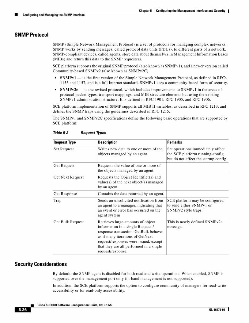
Chapter 5 Configuring the Management Interface and Security Configuring and Managing the SNMP Interface
SNMP Protocol
SNMP (Simple Network Management Protocol) is a set of protocols for managing complex networks. SNMP works by sending messages, called protocol data units (PDUs), to different parts of a network. SNMP-compliant devices, called agents, store data about themselves in Management Information Bases (MIBs) and return this data to the SNMP requesters.
SCE platform supports the original SNMP protocol (also known as SNMPv1), and a newer version called Community-based SNMPv2 (also known as SNMPv2C).
• SNMPv1 — is the first version of the Simple Network Management Protocol, as defined in RFCs 1155 and 1157, and is a full Internet standard. SNMPv1 uses a community-based form of security.
• SNMPv2c — is the revised protocol, which includes improvements to SNMPv1 in the areas of protocol packet types, transport mappings, and MIB structure elements but using the existing SNMPv1 administration structure. It is defined in RFC 1901, RFC 1905, and RFC 1906.
SCE platform implementation of SNMP supports all MIB II variables, as described in RFC 1213, and defines the SNMP traps using the guidelines described in RFC 1215.
The SNMPv1 and SNMPv2C specifications define the following basic operations that are supported by SCE platform:
Security Considerations
By default, the SNMP agent is disabled for both read and write operations. When enabled, SNMP is supported over the management port only (in-band management is not supported).
In addition, the SCE platform supports the option to configure community of managers for read-write accessibility or for read-only accessibility.
Table 5-2 Request Types
Request Type Description Remarks
Set Request Writes new data to one or more of the objects managed by an agent.
Set operations immediately affect the SCE platform running-config but do not affect the startup config
Get Request Requests the value of one or more of the objects managed by an agent.
Get Next Request Requests the Object Identifier(s) and value(s) of the next object(s) managed by an agent.
Get Response Contains the data returned by an agent.
Trap Sends an unsolicited notification from an agent to a manager, indicating that an event or error has occurred on the agent system
SCE platform may be configured to send either SNMPv1 or SNMPv2 style traps.
Get Bulk Request Retrieves large amounts of object information in a single Request / response transaction. GetBulk behaves as if many iterations of GetNext request/responses were issued, except that they are all performed in a single request/response.
This is newly defined SNMPv2c message.
5-26Cisco SCE8000 Software Configuration Guide, Rel 3.1.6S
OL-16479-01

Chapter 5 Configuring the Management Interface and Security Configuring and Managing the SNMP Interface
About CLI
• CLI, page 5-27
• CLI Commands for Configuring SNMP, page 5-27
• CLI Commands for Monitoring SNMP, page 5-27
CLI
The SCE platform supports the CLI commands that control the operation of the SNMP agent. All the SNMP commands are available in Admin authorization level. The SNMP agent is disabled by default and any SNMP configuration command enables the SNMP agent (except where there is an explicit disable command).
CLI Commands for Configuring SNMP
Following is a list of CLI commands available for configuring SNMP. These are Global Configuration mode commands.
• snmp-server enable
• no snmp-server
• [no] snmp-server community [all]
• [no | default] snmp-server enable traps
• [no] snmp-server host [all]
• [no] snmp-server contact
• [no] snmp-server location
CLI Commands for Monitoring SNMP
Following is a list of CLI commands available for monitoring SNMP. These are Viewer mode commands, and are available when the SNMP agent is enabled:
• show snmp (available when SNMP agent is disabled)
• show snmp community
• show snmp contact
• show snmp enabled
• show snmp host
• show snmp location
• show snmp MIB (available when SNMP agent enabled and community was set)
• show snmp traps
About MIBs
MIBs
MIBs (Management Information Bases) are databases of objects that can be monitored by a network management system (NMS). SNMP uses standardized MIB formats that allow any SNMP tools to monitor any device defined by a MIB.
For further information concerning MIBs used by the Cisco SCE8000 platform. (See the Cisco Service Control MIBs, page A-1)
5-27Cisco SCE8000 Software Configuration Guide, Rel 3.1.6S
OL-16479-01

Chapter 5 Configuring the Management Interface and Security Configuring and Managing the SNMP Interface
Configuration via SNMP
SCE platform supports a limited set of variables that may be configured via SNMP (read-write variables). Setting a variable via SNMP (as via the CLI) takes effect immediately and affects only the running-configuration. To make this configuration stored for next reboots (startup-configuration) the user must specify it explicitly via CLI or via SNMP using the Cisco enterprise MIB objects.
It should be noted also that the SCE platform takes the approach of a single configuration database with multiple interfaces that may change this database. Therefore, executing the copy running-config startup-config command via CLI or SNMP makes permanent all the changes made by either SNMP or CLI.
Configuring SNMP Community Strings • How to Define a Community String, page 5-28
• How to Remove a Community String, page 5-29
• How to Display the Configured Community Strings, page 5-29
To enable SNMP management, you must configure SNMP community strings to define the relationship between the SNMP manager and the agent.
After receiving an SNMP request, the SNMP agent compares the community string in the request to the community strings that are configured for the agent. The requests are valid under the following circumstances:
• SNMP Get , Get-next , and Get-bulk requests are valid if the community string in the request matches the read-only community.
• SNMP Get , Get-next , Get-bulk and Set requests are valid if the community string in the request matches the agent’s read-write community.
How to Define a Community String
Options
The following options are available:
• community-string — a security string that identifies a community of managers who are permitted to access the SNMP server
The following keywords are available:
• ro — read only (default accessibility)
• rw — read and write
Step 1 From the SCE(config)# prompt, type snmp-server community community-string ro|rw and press Enter.
Repeat the command as necessary to define all community strings.
5-28Cisco SCE8000 Software Configuration Guide, Rel 3.1.6S
OL-16479-01

Chapter 5 Configuring the Management Interface and Security Configuring and Managing the SNMP Interface
Defining a Community String: Example
This example shows how to configure a community string called “mycommunity” with read-only rights.
Since read-only is the default, it does not need to be defined explicitly.
SCE(config)#snmp-server community mycommunity
How to Remove a Community String
Step 1 From the SCE(config)# prompt, type no snmp-server community community-string and press Enter.
Removing a Community String: Example
The following example shows how to remove a community string called “mycommunity”.
SCE(config)#no snmp-server community mycommunity
How to Display the Configured Community Strings
Step 1 From the SCE> prompt, type show snmp-server community community-string and press Enter.
Displaying the Configured Community Strings: Example
The following example shows how to display the configured SNMP communities.
SCE>show snmp community Community: public, Access Authorization: RO, Access List Index: 1 SCE>
How to Configure SNMP Notifications Use these commands to configure:
• The destinations that will receive SNMP notifications (hosts)
• Which types of notifications will be sent (traps)
• About SNMP Notifications, page 5-29
• How to Define SNMP Hosts, page 5-30
About SNMP Notifications
Notifications are unsolicited messages that are generated by the SNMP agent that resides inside the SCE platform when an event occurs. When the Network Management System receives the notification message, it can take suitable actions, such as logging the occurrence or ignoring the signal.
By default, the SCE platform is not configured to send any SNMP notifications. You must define the Network Management System to which the SCE platform should send notifications. (See the table below, Configurable Notifications, for a list of configurable notifications). Whenever one of the events that trigger notifications occurs in the SCE platform, an SNMP notification is sent from the SCE platform to the list of IP addresses that you define.
5-29Cisco SCE8000 Software Configuration Guide, Rel 3.1.6S
OL-16479-01

Chapter 5 Configuring the Management Interface and Security Configuring and Managing the SNMP Interface
SCE platform supports two general categories of notifications according to the configurations per MIBs. (add here link to the support list --TBD)
SCE platform supports two general categories of notifications:
• Standard SNMP notifications - As defined in RFC1157 and using the conventions defined in RFC1215.
• Proprietary service control enterprise notifications - As defined in the service control proprietary MIB (See Table A-22 on page A-20).
After a host or hosts are configured to receive notifications, by default, the SCE platform sends to the host or hosts all the notifications supported by the SCE platform except for the AuthenticationFailure notification. The SCE platform provides the option to enable or disable the sending of this notification, as well as some of the SCE enterprise notifications, explicitly.
SCE platform can be configured to generate either SNMPv1 style or SNMPv2c style notifications. By default, the SCE platforms sends SNMPv1 notifications.
Following are some sample procedures illustrating how to do the following:
• Configure hosts (NMS) to which the SNMP agent should send notifications
• Remove/disable a host (NMS) from receiving notifications
• Enable the SNMP agent to send authentication-failure notifications
• Enable the SNMP agent to send enterprise notifications
• Reset all notifications to the default setting
How to Define SNMP Hosts
Use this command to define the hosts that will receive notifications from the SCE platform.
• Options, page 5-30
• How to Configure the SCE Platform to Send Notifications to a Host (NMS), page 5-31
• How to Configure the SCE Platform to Stop Sending Notifications to a Host, page 5-31
• How to Configure SNMP Traps, page 5-31
Options
The following options are available:
• ip-address — the IP address of the SNMP server host
• community-string — a security string that identifies a community of managers who are permitted to access the SNMP server
• version — SNMP version running in the system. Can be set to 1 or 2c.
– Default — 1 (SNMPv1)
5-30Cisco SCE8000 Software Configuration Guide, Rel 3.1.6S
OL-16479-01

Chapter 5 Configuring the Management Interface and Security Configuring and Managing the SNMP Interface
How to Configure the SCE Platform to Send Notifications to a Host (NMS)
Step 1 At the SCE(config)# prompt, type snmp-server host ip-address community-string and press Enter.
If the version is not specified, SNMPv1 is assumed.
Only one host can be specified per command. To define multiple hosts, execute one command for each host.
Configuring the SCE Platform to Send Notifications to Multiple Hosts: Example
The following example shows how to configure the SCE platform to send SNMPv1 notifications to several hosts.
SCE(config)#snmp-server host 10.10.10.10 mycommunity SCE(config)#snmp-server host 20.20.20.20 mycommunity SCE(config)#snmp-server host 30.30.30.30 mycommunity SCE(config)#snmp-server host 40.40.40.40 mycommunity
How to Configure the SCE Platform to Stop Sending Notifications to a Host
Step 1 At the SCE(config)# prompt, type no snmp-server host ip-address and press Enter.
Configuring the SCE Platform to Stop Sending Notifications to a Host: Example
The following example shows how to remove the host with the IP Address: “192.168.0.83”.
SCE(config)#no snmp-server host 192.168.0.83
How to Configure SNMP Traps
Use this command to configure the notifications that will be sent to the defined host.
• Options, page 5-31
• How to Enable the SNMP Server to Send Authentication Failure Notifications, page 5-32
• How to Enable the SNMP Server to Send All Enterprise Notifications, page 5-32
• How to Enable the SNMP Server to Send a specific Enterprise Notification, page 5-32
• How to Restore All Notifications to the Default Status, page 5-32
Options
The following options are available:
• snmp — optional parameter that specifies that all or specific snmp traps should be enabled or disabled.
By default, snmp traps are disabled.
snmp trap name — optional parameter that specifies a specific snmp trap that should be enabled or disabled.
Currently the only accepted value for this parameter is Authentication .
• enterprise — optional parameter that specifies that all or specific enterprise traps should be enabled or disabled.
By default, enterprise traps are enabled.
5-31Cisco SCE8000 Software Configuration Guide, Rel 3.1.6S
OL-16479-01

Chapter 5 Configuring the Management Interface and Security Configuring and Managing the SNMP Interface
• enterprise trap name — optional parameter that specifies a specific snmp trap that should be enabled or disabled.
Values: attack, chassis, link-bypass, logger, operational-status, port-operational-status, pull-request-failure, RDR-formatter, session, SNTP, subscriber, system-reset, telnet, vas-traffic-forwarding
Use these parameters as follows:
• To enable/disable all traps of one type: Specify only snmp or enterprise .
• To enable/disable only one specific trap: Specify snmp or enterprise with the additional trap name parameter naming the desired trap.
• To enable/disable all traps: Do not specify either snmp or enterprise .
How to Enable the SNMP Server to Send Authentication Failure Notifications
Step 1 At the SCE(config)# prompt, type snmp-server enable traps snmp authentication and press Enter.
How to Enable the SNMP Server to Send All Enterprise Notifications
Step 1 At the SCE(config)# prompt, type snmp-server enable traps enterprise and press Enter.
How to Enable the SNMP Server to Send a specific Enterprise Notification
Step 1 At the SCE(config)# prompt, type snmp-server enable traps enterprise [attack|chassis|link-bypass|logger|operational-status|port-operational-status|pull-request-failure|RDR-formatter|session| SNTP|subscriber|system-reset|telnet|vas-traffic-forwarding] and press Enter.
Specify the desired enterprise trap type.
Enabling the SNMP Server to Send a Specific Enterprise Notification: Example
The following example shows how to configure the SNMP server to send the logger enterprise notification only.
SCE(config)#snmp-server enable traps enterprise logger
How to Restore All Notifications to the Default Status
Step 1 At the SCE(config)# prompt, type default snmp-server enable traps and press Enter.
Resets all notifications supported by the SCE platform to their default status.
5-32Cisco SCE8000 Software Configuration Guide, Rel 3.1.6S
OL-16479-01

Chapter 5 Configuring the Management Interface and Security IP Configuration
IP Configuration • Configuring the IP Routing Table, page 5-33
• IP Advertising, page 5-35
• How to Configure the IP Address of the Management Interface, page 5-37
Configuring the IP Routing Table • About the IP Routing Table, page 5-33
• How to Configure the Default Gateway, page 5-34
• How to Add an Entry to the IP Routing Table, page 5-34
• How to Display the IP Routing Table, page 5-34
About the IP Routing Table
For handling IP packets on the out-of-band MNG port, the SCE platform maintains a static routing table. When a packet is sent, the system checks the routing table for proper routing, and forwards the packet accordingly. In cases where the SCE platform cannot determine where to route a packet, it sends the packet to the default gateway.
SCE platform supports the configuration of the default gateway as the default next hop router, as well as the configuration of the routing table to provide different next hop routers for different subnets (for maximum configuration of 10 subnets).
The following sections illustrate how to use CLI commands to configure various parameters.
The following commands are relevant to IP routing tables:
• ip default-gateway
• ip route prefix mask next-hop
• no ip route all
• no ip route prefix mask
• show ip route
• show ip route prefix
• show ip route prefix mask
5-33Cisco SCE8000 Software Configuration Guide, Rel 3.1.6S
OL-16479-01

Chapter 5 Configuring the Management Interface and Security IP Configuration
How to Configure the Default Gateway
Options
The following option is available:
• ip-address—the IP address of the default gateway.
Step 1 From the SCE(config)# prompt, type ip default-gateway ip-address, and press Enter.
Enables privileged EXEC mode.
• Enter your password if prompted.
Configuring the Default Gateway: Example
The following example shows how to set the default gateway IP of the SCE platform to 10.1.1.1.
SCE(config)#ip default-gateway 10.1.1.1
How to Add an Entry to the IP Routing Table
Options
The following options are available:
• prefix — IP address of the routing entry, in dotted notation.
• mask — The relevant subnet mask, in dotted notation
• next-hop — The IP address of the next hop in the route, in dotted notation.
Must be within the MNG interface subnet.
Step 1 From the SCE(config)# prompt, type ip route prefix mask next-hop, and press Enter.
Adds the specified IP routing entry to the routing table.
How to Add an Entry to the IP Routing Table: Example
The following example shows how to set the router 10.1.1.250 as the next hop to subnet 10.2.0.0.
SCE(config)#ip route 10.2.0.0 255.255.0.0 10.1.1.250
How to Display the IP Routing Table
• How to Display the Entire IP Routing Table, page 5-34
• How to Display the IP Routing Table for a Specified Subnet, page 5-35
How to Display the Entire IP Routing Table
Step 1 From the SCE# prompt, type show ip route and press Enter.
Displays the entire routing table and the destination of last resort (default-gateway)
5-34Cisco SCE8000 Software Configuration Guide, Rel 3.1.6S
OL-16479-01
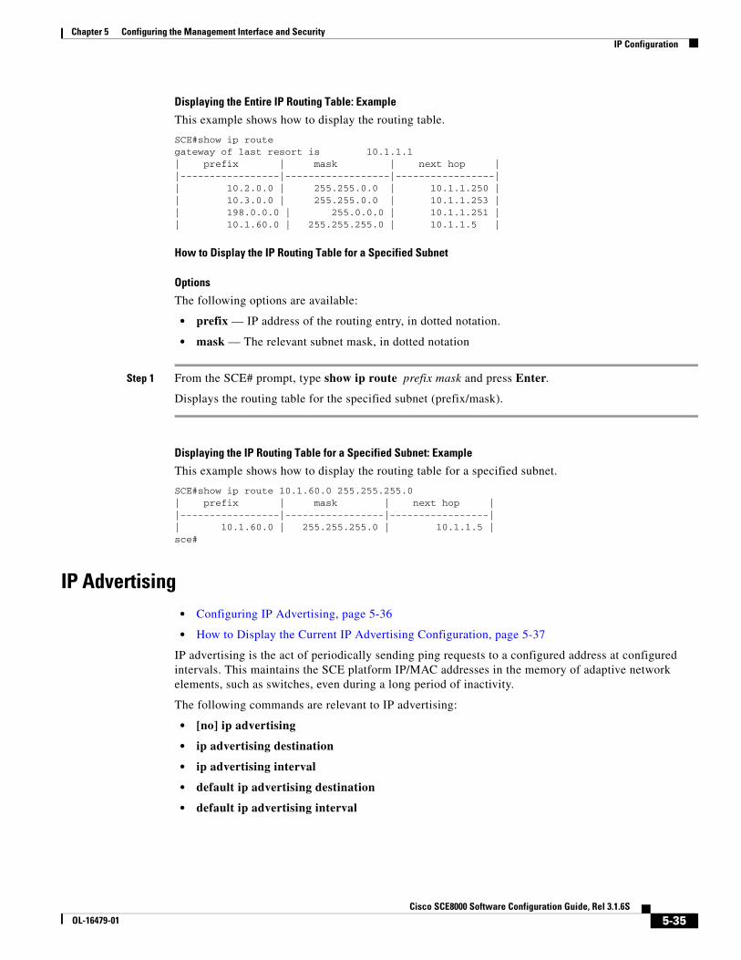
Chapter 5 Configuring the Management Interface and Security IP Configuration
Displaying the Entire IP Routing Table: Example
This example shows how to display the routing table.
SCE#show ip route gateway of last resort is 10.1.1.1 | prefix | mask | next hop | |-----------------|------------------|-----------------| | 10.2.0.0 | 255.255.0.0 | 10.1.1.250 | | 10.3.0.0 | 255.255.0.0 | 10.1.1.253 | | 198.0.0.0 | 255.0.0.0 | 10.1.1.251 | | 10.1.60.0 | 255.255.255.0 | 10.1.1.5 |
How to Display the IP Routing Table for a Specified Subnet
Options
The following options are available:
• prefix — IP address of the routing entry, in dotted notation.
• mask — The relevant subnet mask, in dotted notation
Step 1 From the SCE# prompt, type show ip route prefix mask and press Enter.
Displays the routing table for the specified subnet (prefix/mask).
Displaying the IP Routing Table for a Specified Subnet: Example
This example shows how to display the routing table for a specified subnet.
SCE#show ip route 10.1.60.0 255.255.255.0 | prefix | mask | next hop | |-----------------|-----------------|-----------------| | 10.1.60.0 | 255.255.255.0 | 10.1.1.5 | sce#
IP Advertising • Configuring IP Advertising, page 5-36
• How to Display the Current IP Advertising Configuration, page 5-37
IP advertising is the act of periodically sending ping requests to a configured address at configured intervals. This maintains the SCE platform IP/MAC addresses in the memory of adaptive network elements, such as switches, even during a long period of inactivity.
The following commands are relevant to IP advertising:
• [no] ip advertising
• ip advertising destination
• ip advertising interval
• default ip advertising destination
• default ip advertising interval
5-35Cisco SCE8000 Software Configuration Guide, Rel 3.1.6S
OL-16479-01

Chapter 5 Configuring the Management Interface and Security IP Configuration
• show ip advertising
• show ip advertising destination
• show ip advertising interval
Configuring IP Advertising
To configure IP advertising, you must first enable IP advertising. You may then specify a destination address to which the ping request is to be sent and/or the frequency of the ping requests (interval). If no destination or interval is explicitly configured, the default values are assumed.
Options
The following options are available in the IP advertising commands:
• interval — The time interval between pings in seconds.
default interval = 300 seconds
• destination — The IP address of the destination for the ping requests
default destination = 127.0.0.1
How to Enable IP Advertising
Step 1 From the SCE(config)# prompt, type ip advertising and press Enter.
Enables IP advertising.
How to Configure the IP Advertising Destination
Step 1 From the SCE(config)# prompt, type ip advertising destination destination, and press Enter.
Configures the destination for the IP advertising pings.
How to Configure the IP Advertising Interval
Step 1 From the SCE(config)# prompt, type ip advertising interval interval, and press Enter.
Configures the frequency of the IP advertising pings.
Configuring IP Advertising: Example
The following example shows how to configure IP advertising, specifying 10.1.1.1 as the destination and an interval of 240 seconds.
SCE(config)#ip advertising destination 10.1.1.1SCE(config)#ip advertising interval 240
5-36Cisco SCE8000 Software Configuration Guide, Rel 3.1.6S
OL-16479-01

Chapter 5 Configuring the Management Interface and Security IP Configuration
How to Display the Current IP Advertising Configuration
Step 1 From the SCE# prompt, type show ip advertising and press Enter.
Displays the status of IP advertising (enabled or disabled), the configured destination, and the configured interval
How to Configure the IP Address of the Management Interface The user must define the IP address of the management interface.
Note Changing the IP address of the management interface via telnet will result in loss of the telnet connection and inability to reconnect with the interface.
Note After changing the IP address, you must reload the SCE platform (See Rebooting and Shutting Down the SCE Platform, page 3-14) so that the change will take effect properly in all internal and external components of the SCE platform.
Options
The following options are available:
• ip-address — The IP address of the management interface. If both management ports are connected, so that a backup management link is available, this IP address will be act as a virtual IP address for the currently active management port, regardless of which physical port is currently active.
• subnet mask — subnet mask of the management interface.
Step 1 Connect the SCE platform directly to a local console.
Establishes contact with the SCE platform that is not dependent on the configured IP address.
Step 2 From the SCE(config if)# prompt, type ip address ip-address subnet-mask and press Enter.
Configures a new IP address for the management interface
The command might fail if there is a routing table entry that is not part of the new subnet defined by the new IP address and subnet mask..
Configuring the IP Address of the Management Interface: Example
The following example shows how to set the IP address of the SCE platform to 10.1.1.1 and the subnet mask to 255.255.0.0.
SCE(config if)#ip address 10.1.1.1 255.255.0.0
5-37Cisco SCE8000 Software Configuration Guide, Rel 3.1.6S
OL-16479-01

Chapter 5 Configuring the Management Interface and Security Configuring Time Clocks and Time Zone
Configuring Time Clocks and Time Zone • Displaying the System Time, page 5-38
• Displaying the Calendar Time, page 5-39
• Setting the System Clock, page 5-39
• Setting the Calendar, page 5-39
• Setting the Time Zone, page 5-40
• Removing the Current Time Zone Setting, page 5-41
• Configuring Daylight Saving Time, page 5-41
The SCE platform has three types of time settings, which can be configured: the clock, the calendar, and the time zone. It is important to synchronize the clock and calendar to the local time, and to set the time zone properly. The SCE platform does not track Daylight Saving Time automatically, so you must update the time zone when the time changes bi-annually.
The SCE platform has the following two time sources:
• A real-time clock, called the calendar, that continuously keeps track of the time, even when the SCE platform is not powered up. When the SCE platform reboots, the calendar time is used to set the system clock. The calendar is not used for time tracking during system operation.
• A system clock, which creates all the time stamps during normal operation. This clock clears if the system shuts down. During a system boot, the clock is initialized to show the time indicated by the calendar.
It does not matter which clock you set first, as long as you use the clock and calendar read commands to ensure they are synchronized.
The time zone settings are important because they allow the system to communicate properly with other systems in other time zones. The system is configured based on Coordinated Universal Time (UTC), which is standard in the industry for coordination with other manufacturers’ hardware and software. For example, Pacific Standard Time would be written as PST-10, meaning that the name of the time zone is PST, which is 10 hours behind Universal Time.
When setting and showing the time, the time is always typed or displayed according to the local time zone configured.
Displaying the System Time
Step 1 From the SCE(config)# prompt, type show clock and press Enter.
Displaying the System Time: Example
The following example shows the current system clock.
SCE#show clock 12:50:03 UTC MON November 13 2001 sce#
5-38Cisco SCE8000 Software Configuration Guide, Rel 3.1.6S
OL-16479-01

Chapter 5 Configuring the Management Interface and Security Configuring Time Clocks and Time Zone
Displaying the Calendar Time
Step 1 From the SCE(config)# prompt, type show calendar and press Enter.
Displaying the Calendar Time: Example
The following example shows the current system calendar.
SCE#show calendar 12:50:03 UTC MON May 11 2007 sce#
Setting the System Clock
Options
The following option is available:
• time-date the time and date you want to set, in the following format:
hh:mm:ss day month year
Step 1 From the SCE# prompt, type clock set time-date and press Enter.
Sets the system clock to the specified time and date.
Setting the System Clock: Example
The following example shows how to set the clock to 20 minutes past 10 AM, May 13, 2007, updates the calendar and then displays the time.
SCE#clock set 10:20:00 13 may 2007 SCE#clock update-calendar SCE#show clock 10:21:10 UTC THU May 13 2007
Setting the Calendar The calendar is a system clock that continues functioning even when the system shuts down.
Options
The following option is available:
• time-date —the time and date you want to set, in the following format:
hh:mm:ss day month year
5-39Cisco SCE8000 Software Configuration Guide, Rel 3.1.6S
OL-16479-01

Chapter 5 Configuring the Management Interface and Security Configuring Time Clocks and Time Zone
Step 1 From the SCE# prompt, type calendar set time-date and press Enter.
Sets the system calendar to the specified time and date.
The time specified in this command is relative to the configured time zone.
Step 2 From the SCE# prompt, type clock read-calendar and press Enter.
Synchronizes the system clock with the calendar time you just set .
Setting the Calendar: Example
The following example shows that the calendar is set to 10:20 AM, May 13, 2007. The clock is then synchronized with the calendar setting.
SCE#calendar set 10:20:00 13 may 20017 SCE#clock read-calendar SCE#show calendar 10:21:06 UTC THU May 13 2007
Setting the Time Zone
Options
The following options are available:
• zone — The name of the time zone to be displayed.
default = GMT
• hours — The hours offset from UTC. This must be an integer in the range –23 to 23.
default = 0
• minutes — The minutes offset from UTC. This must be an integer in the range of 0 to 59. Use this parameter to specify an additional offset in minutes when the offset is not measured in whole hours.
default = 0
Step 1 From the SCE(config)# prompt, type clock timezone zone hours minutes and press Enter.
Sets the timezone to the specified timezone name with the configured offset in hours and minutes.
Setting the Time Zone: Example
The following example shows how to set the time zone to Pacific Standard Time with an offset of 10 hours behind UTC.
SCE(config)#clock timezone PST –10 SCE(config)#
5-40Cisco SCE8000 Software Configuration Guide, Rel 3.1.6S
OL-16479-01

Chapter 5 Configuring the Management Interface and Security Configuring Time Clocks and Time Zone
Removing the Current Time Zone Setting
Step 1 From the SCE(config)# prompt, type no clock timezone and press Enter.
Removes the timezone configuration and resets the timezone to the default value (UTC).
Configuring Daylight Saving Time The SCE platform can be configured to automatically switch to daylight saving time on a specified date, and also to switch back to standard time. In addition, the time zone code can be configured to vary with daylight saving time if required. (For instance, in the eastern United States, standard time is designated EST, and daylight saving time is designated EDT).
• Options, page 5-41
• Guidelines, page 5-42
• How to Define Recurring Daylight Saving Time Transitions, page 5-42
• How to Define Non-Recurring Daylight Saving Time Transitions, page 5-43
• How to Cancel the Daylight Saving Time Configuration, page 5-43
• How to Display the Current Daylight Saving Time Configuration, page 5-43
Options
The transition times into and out of daylight saving time may be configured in one of two ways, depending on how the dates for the beginning and end of daylight saving time are determined for the particular location:
• recurring — If daylight saving time always begins and ends on the same day every year, (as in the United States), the clock summer-time recurring command is used. The beginning and ending days for daylight saving time can be configured once, and the system will automatically perform the switch every year.
• not recurring — If the start and end of daylight saving time is different every year, (as in Israel), the clock summer-time command is used. In this case, the transitions must be configured every year for that particular year.
Note The "year" is not necessarily a calendar year. If the transition days are determined in the fall, the transitions for that fall and the next spring may be configured.
The day on which the transition takes place may be defined in several ways:
• Specific date — For example, March 29, 2004. A specific date, including the year, is defined for a not recurring configuration.
• First/last occurrence of a day of the week in a specified month — For example, the last Sunday in March. This is used for a recurring configuration.
• Day of the week in a specific week in a specified month — For example, Sunday of the fourth week of March. (This would be different from the last Sunday of the month whenever there were five Sundays in the month). This is used for a recurring configuration.
5-41Cisco SCE8000 Software Configuration Guide, Rel 3.1.6S
OL-16479-01

Chapter 5 Configuring the Management Interface and Security Configuring Time Clocks and Time Zone
The following options are available:
• zone — the time zone code for daylight saving time
• week (recurring only)— the week of the month on which daylight saving begins (week1) and ends (week2)
• day (recurring only) — the day of the week on which daylight savings begin (day1) and ends (day2)
• date (non-recurring only) — the date of the month on which daylight saving begins (date1) and ends (date2)
• month — the month in which daylight saving begins (month1) and ends (month2)
• year (non-recurring only) — the year in which daylight saving begins (year1) and ends (year2)
• offset — the difference in minutes between standard time and daylight saving time.
Default = 60 minutes
Guidelines
General guidelines for configuring daylight saving time transitions:
• Specify the time zone code for daylight saving time.
• recurring — specify a day of the month (week#|first|last/day of the week/month).
• not recurring — specify a date (month/day of the month/year).
• Define two days:
– Day1 = beginning of daylight saving time.
– Day2 = end of daylight saving time.
• In the Southern hemisphere, month2 must be before month1, as daylight saving time begins in the fall and ends in the spring.
• Specify the exact time that the transition should occur (24 hour clock).
– Time of transition into daylight saving time — according to local standard time.
– Time of transition out of daylight saving time — according to local daylight savings time.
• For the clock summer-time recurring command, the default values are the United States transition rules:
– Daylight saving time begins: 2:00 (AM) on the second Sunday of March.
– Daylight saving time ends: 2:00 (AM) on the first Sunday of November.
How to Define Recurring Daylight Saving Time Transitions
Step 1 From the SCE(config)# prompt, type clock summer-time zone recurring [week1 day1 month1 time1 week2 day2 month2 time2 [ offset ]] and press Enter.
Configures daylight saving time to start and stop on the specified days every year.
5-42Cisco SCE8000 Software Configuration Guide, Rel 3.1.6S
OL-16479-01

Chapter 5 Configuring the Management Interface and Security Configuring Time Clocks and Time Zone
Defining Recurring Daylight Saving Time Transitions: Example
The following example shows how to configure recurring daylight saving time for a time zone designated "DST" as follows:
• Daylight saving time begins — 0:00 on the last Sunday of March.
• Daylight saving time ends — 23:59 on the Saturday of fourth week of November.
• Offset = 1 hour (default.
SCE(config)# clock summer-time DST recurring last Sunday March 00:00 4 Saturday November 23:59
How to Define Non-Recurring Daylight Saving Time Transitions
Step 1 From the SCE(config)# prompt, type clock summer-time zone [ date1 month1 year1 time1 date2 month2 year2 time2 [ offset ]] and press Enter.
Defining Non-Recurring Daylight Saving Time Transitions: Example
The following example shows how to configure non-recurring daylight saving time for a time zone designated "DST" as follows:
• Daylight saving time begins — 0:00 on April 16, 2004.
• Daylight saving time ends — 23:59 October 23, 2004.
• Offset = 1 hour (default)
SCE(config)# clock summer-time DST April 16 2004 00:00 October 23 2004 23:59
How to Cancel the Daylight Saving Time Configuration
Step 1 From the SCE(config)# prompt, type no clock summer-time and press Enter.
Removes all daylight saving configuration.
How to Display the Current Daylight Saving Time Configuration
Step 1 From the SCE# prompt, type show timezone and press Enter.
Displays the current time zone and daylight saving time configuration.
5-43Cisco SCE8000 Software Configuration Guide, Rel 3.1.6S
OL-16479-01

Chapter 5 Configuring the Management Interface and Security Domain Name Server (DNS) Settings
Domain Name Server (DNS) Settings • Configuring DNS Lookup, page 5-44
• Configuring Name Servers, page 5-45
• How to Add a Host to the Host Table, page 5-46
• How to Display Current DNS Settings, page 5-46
When a name of a host is given as a parameter to a CLI command that expects a host name or an IP address, the system translates the name to an IP address according to the following:
1. If the name is in a dotted decimal notation (that is, in the format x.x.x.x), it is directly translated to an IP address it represents.
2. If the name does not contain the dot character (.), the system looks it up in the IP Host table. If the name is found on the table, it is mapped to the corresponding IP address. The IP host table can be configured using the command ip host.
3. If the name does not contain the dot (.) character, and the domain name function is enabled (See the ip domain-lookup command), and a default domain name is specified (See the ip domain-name command), the default domain name is appended to the given name to form a fully qualified host name. This, in turn, is used to perform a DNS query translating the name to an IP address.
4. Otherwise, if the domain name function is enabled, the name is considered to be fully qualified, and is used to perform a DNS query translating the name to an IP address.
The following commands are relevant to DNS settings:
• ip name-server
• ip domain-name
• no ip domain-name
• ip domain-lookup
• show hosts
Configuring DNS Lookup
How to Enable DNS Lookup
Step 1 From the SCE(config)# prompt, type ip domain-lookup and press Enter.
Enables DNS lookup.
How to Disable DNS Lookup
Step 1 From the SCE(config)# prompt, type no ip domain-lookup and press Enter.
5-44Cisco SCE8000 Software Configuration Guide, Rel 3.1.6S
OL-16479-01

Chapter 5 Configuring the Management Interface and Security Domain Name Server (DNS) Settings
Configuring Name Servers • Options, page 5-45
• How to Define Domain Name Servers, page 5-45
• How to Remove a Domain Name Server, page 5-45
• How to Remove All Domain Name Servers, page 5-46
Options
The following options are available:
• server-ip-address — The IP address of the domain name server. You can define more than one DNS server (server-ip-address1, server-ip-address2, server-ip-address3)
How to Define Domain Name Servers
Use this command to specify the address of one or more name servers to use for name and address resolution.
Step 1 From the SCE(config)# prompt, type ip name-server server-address1 [server-address2 [server-address3]] and press Enter.
Defines the servers at the specified addresses as domain name servers.
Defining Domain Name Servers: Example
The following example shows how to configure the two name server (DNS) IP addresses.
SCE(config)#ip name-server 10.1.1.60 10.1.1.61
How to Remove a Domain Name Server
Step 1 From the SCE(config)# prompt, type no ip name-server server-address1 [server-address2 [server-address3]] and press Enter.
Removes the specified server from the DNS list.
Removing a Domain Name Server: Example
The following example shows how to remove name server (DNS) IP addresses.
SCE(config)#no ip name-server 10.1.1.60 10.1.1.61
5-45Cisco SCE8000 Software Configuration Guide, Rel 3.1.6S
OL-16479-01

Chapter 5 Configuring the Management Interface and Security Domain Name Server (DNS) Settings
How to Remove All Domain Name Servers
Step 1 From the SCE(config)# prompt, type no ip name-server and press Enter.
Removes all configured DNS servers.
How to Add a Host to the Host Table
Options
The following options are available:
• hostname — The name of the host.
• ip-address — The IP address of the host
Step 1 From the SCE(config)# prompt, type ip host hostname ip-address and press Enter.
Adds the specified host to the host table.
Adding Hosts to Removing them from the Host Table: Examples
The following example shows how to add a host to the host table.
SCE(config)#ip host PC85 10.1.1.61
The following example shows how to remove a hostname together with all its IP mappings.
SCE(config)#no ip host PC85
How to Display Current DNS Settings
Step 1 From the SCE# prompt, type show hosts and press Enter.
Displays current DNS settings.
Displaying Current DNS Settings: Example
The following example shows how to display current DNS information.
SCE#show hosts Default domain is Cisco.com Name/address lookup uses domain service Name servers are 10.1.1.60, 10.1.1.61 Host Address ---- ------- PC85 10.1.1.61 sce#
5-46Cisco SCE8000 Software Configuration Guide, Rel 3.1.6S
OL-16479-01

OL-16479-02
C H A P T E R 6
Configuring the Line InterfaceThis module describes how to configure the physical line interfaces (ports) as well as how to configure those interfaces for tunneling, VLAN translation, DSCP marking, and traffic rules.
• Line Interfaces, page 6-1
• Tunneling Protocols, page 6-2
• Configuring Traffic Rules and Counters, page 6-8
• DSCP Marking, page 6-16
• Counting Dropped Packets, page 6-16
Line Interfaces The Line Interfaces (Subscriber and Network) are used to connect the SCE platform to the network. See the description of network topologies in the Topology section of the Cisco SCE8000 Installation and Configuration Guide.
Flow Control and Bandwidth Considerations
Note By design, the SCE platform reacts to Ethernet flow control and does not activate it. Therefore, it is possible for a situation to arise in which flow control actually stalls the SCE platform by overflowing the SCE platform queues, thereby causing traffic to be dropped on the Rx interfaces. If this situation persists for more than five seconds, it may trigger the internal sanity checks mechanism within the SCE platform, which may in turn trigger a reload of the SCE platform in an attempt to recover
Maximum Packet Size
The MTU value for the Cisco SCE8000 traffic processing is 9238 bytes. However, in the current version, packets larger than 1600 bytes are bypassed and are not handled by the service control application.
6-1Cisco SCE8000 Software Configuration Guide
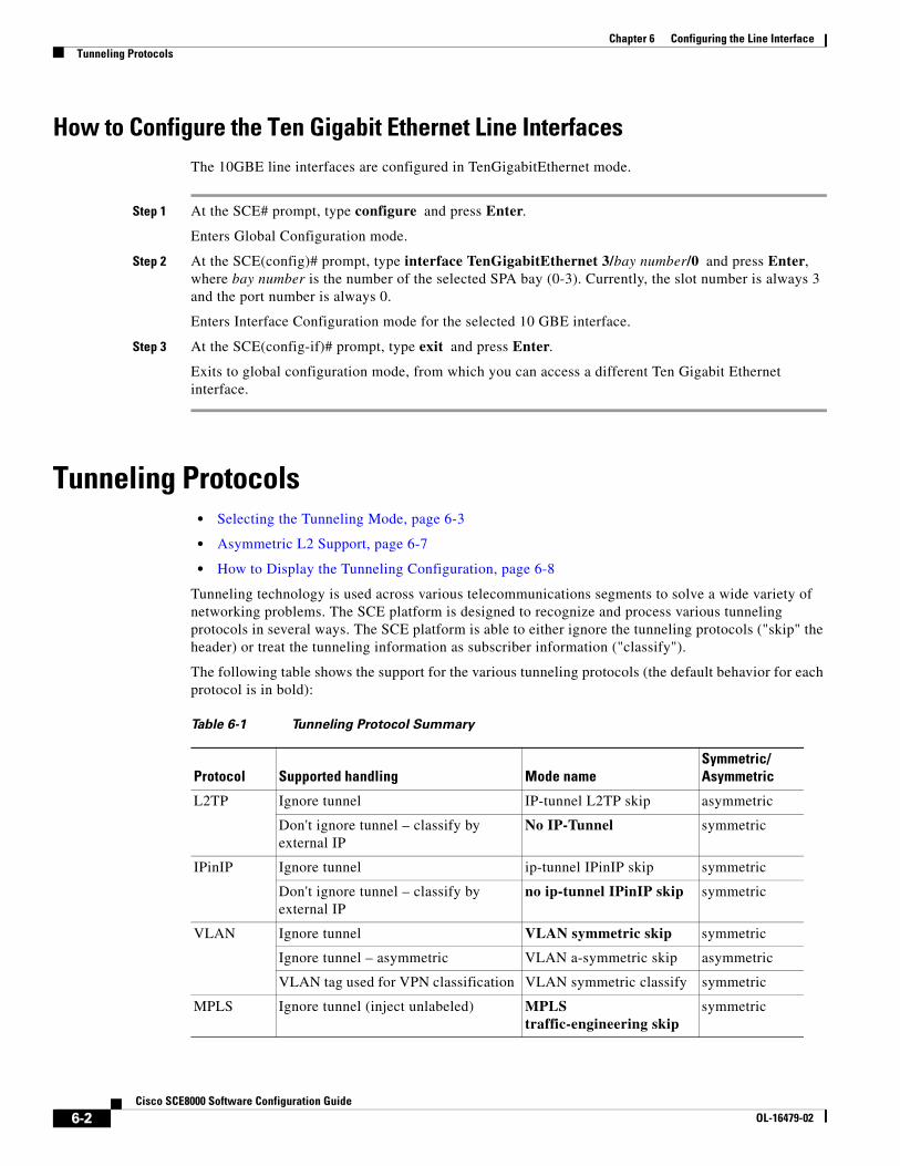
Chapter 6 Configuring the Line InterfaceTunneling Protocols
How to Configure the Ten Gigabit Ethernet Line Interfaces The 10GBE line interfaces are configured in TenGigabitEthernet mode.
Step 1 At the SCE# prompt, type configure and press Enter.
Enters Global Configuration mode.
Step 2 At the SCE(config)# prompt, type interface TenGigabitEthernet 3/bay number/0 and press Enter, where bay number is the number of the selected SPA bay (0-3). Currently, the slot number is always 3 and the port number is always 0.
Enters Interface Configuration mode for the selected 10 GBE interface.
Step 3 At the SCE(config-if)# prompt, type exit and press Enter.
Exits to global configuration mode, from which you can access a different Ten Gigabit Ethernet interface.
Tunneling Protocols • Selecting the Tunneling Mode, page 6-3
• Asymmetric L2 Support, page 6-7
• How to Display the Tunneling Configuration, page 6-8
Tunneling technology is used across various telecommunications segments to solve a wide variety of networking problems. The SCE platform is designed to recognize and process various tunneling protocols in several ways. The SCE platform is able to either ignore the tunneling protocols ("skip" the header) or treat the tunneling information as subscriber information ("classify").
The following table shows the support for the various tunneling protocols (the default behavior for each protocol is in bold):
Table 6-1 Tunneling Protocol Summary
Protocol Supported handling Mode nameSymmetric/ Asymmetric
L2TP Ignore tunnel IP-tunnel L2TP skip asymmetric
Don't ignore tunnel – classify by external IP
No IP-Tunnel symmetric
IPinIP Ignore tunnel ip-tunnel IPinIP skip symmetric
Don't ignore tunnel – classify by external IP
no ip-tunnel IPinIP skip symmetric
VLAN Ignore tunnel VLAN symmetric skip symmetric
Ignore tunnel – asymmetric VLAN a-symmetric skip asymmetric
VLAN tag used for VPN classification VLAN symmetric classify symmetric
MPLS Ignore tunnel (inject unlabeled) MPLS traffic-engineering skip
symmetric
6-2Cisco SCE8000 Software Configuration Guide
OL-16479-02

Chapter 6 Configuring the Line InterfaceTunneling Protocols
When the tunneling information is ignored, the subscriber identification is the subscriber IP of the IP packet carried inside the tunnel.
Asymmetric Tunneling
Some tunneling modes are symmetric and some are asymmetric (see Table 6-1). Any time that one of the asymmetric tunneling modes is enabled, the entire system is automatically set to asymmetric flow open mode. In this mode, flows are opened earlier than in symmetric flow open mode, and the first packet of each direction of the flow (upstream and downstream) reaches the software. This is required to support redirect and block operations over asymmetric layer 2 protocols. However, it also has some performance impact, so that a certain performance degradation should be expected in any asymmetric mode.
It is also possible to explicitly configure the system to treat all flows as having asymmetric layer 2 characteristics (including Ethernet, VLAN, MPLS, and L2TP), for the purpose of packet injection (such as block flow and redirect flow operations).
To view the effective flow open mode, use the show interface linecard 0 flow-open-mode command.
Note For directions on how to configure the asymmetric tunneling option, see Asymmetric L2 Support, page 6-7
L2TP
L2TP is an IP-based tunneling protocol, therefore the system must be specifically configured to recognize the L2TP flows, given the UDP port used for L2TP. The SCE platform can then skip the external IP, UDP, and L2TP headers, reaching the internal IP, which is the actual subscriber traffic. If L2TP is not configured, the system treats the external IP header as the subscriber traffic, thus all the flows in the tunnel are seen as a single flow.
VLAN
A single VLAN tag is supported per packet (no QinQ support).
Subscriber classification by VLAN tag is supported only in symmetric VLAN environments – i.e. where the upstream and downstream tags of a flow are identical.
Selecting the Tunneling Mode • How to Configure IP Tunnels, page 6-4
• IPinIP Tunneling, page 6-4
• How to Configure the VLAN Environment, page 6-6
• How to Configure the L2TP Environment, page 6-6
Use these commands to configure tunneling:
• ip-tunnel
• vlan
• L2TP identify-by
6-3Cisco SCE8000 Software Configuration Guide
OL-16479-02
Chapter 6 Configuring the Line InterfaceTunneling Protocols
How to Configure IP Tunnels
By default, IP tunnel recognition is disabled. Use this command to configure recognition of L2TP tunnels and skipping into the internal IP packet.
Step 1 From the SCE(config if)# prompt, type ip-tunnel L2TP skip and press Enter.
To disable IP tunnels, use the following command:
Step 1 From the SCE(config if)# prompt, type no ip-tunnel and press Enter.
Note The IP tunneling mode is mutually exclusive with VPN-based classification.
IPinIP Tunneling
• Enabling IPinIP Tunneling, page 6-4
• Disabling IPinIP Tunneling, page 6-5
• DSCP Marking for IPinIP Tunnels, page 6-5
IPinIP is an IP-based tunneling protocol; therefore the system must be specifically configured to recognize the flows inside the tunnel. The SCE platform will then skip the external IP header, reaching the internal IP, which is the actual subscriber traffic. When IPinIP skip is disabled, the system treats the external IP header as the subscriber traffic, resulting in all IPinIP traffic being reported as generic IP.
Guidelines for configuring IPinIP tunnels:
• IPinIP and other tunnels: IPinIP is supported simultaneously with plain IP traffic and any other tunneling protocol supported by the SCE platform.
• Overlapping IP addresses: There is no support for overlapping IP addresses within different IPinIP tunnels.
• DSCP marking: For IPinIP traffic, DSCP marking can be done on either the external or the internal IP header exclusively. See Disabling IPinIP Tunneling, page 6-5.
Fragmentation
Fragmentation should be avoided whenever possible. If it is not possible to avoid fragmentation, it is recommended to opt for internal fragmentation. If that is also not possible, the SCE platform can be operated under conditions of external fragmentation
Enabling IPinIP Tunneling
By default, IP tunnel recognition is disabled. Use this command to configure recognition of IPinIP tunnels and skipping into the internal IP packet.
Step 1 From the SCE(config-if)# prompt, type ip-tunnel IPinIP skip and press Enter.
6-4Cisco SCE8000 Software Configuration Guide
OL-16479-02

Chapter 6 Configuring the Line InterfaceTunneling Protocols
Disabling IPinIP Tunneling
Step 1 From the SCE(config-if)# prompt, type no ip-tunnel IPinIP skip and press Enter.
DSCP Marking for IPinIP Tunnels
DSCP marking modifies the DSCP bits of the IPv4 header. In IPinIP tunnels there are at least two IP headers. By default, DSCP marking is performed only on the external IP header (refer to the illustration below).
Figure 6-1 DSCP Marking for IPinIP Tunnels
Note DSCP marking should be enabled and configured through SCA BB console. Refer to the section “How to Manage DSCP Marker Values" in the chapter "Using the Service Configuration Editor: Traffic Control" in the Cisco Service Control Application for Broadband User Guide for further information.
Use this command to configure the SCE platform to mark the DSCP bits of the internal IP header. This command takes effect only when IPinIP skip is enabled.
Step 1 From the SCE(config-if)# prompt, type ip-tunnel IPinIP DSCP-marking-skip and press Enter.
Enables DSCP marking on the internal IP header of IPinIP traffic.
Version H Len TOS Total Length
Identification Fragment OffsetFlags
TTL Protocol Header Checksum
Source Address
Destination Address
Version H Len TOS Total Length
Identification Fragment OffsetFlags
TTL Protocol Header Checksum
Source Address
Destination Address
L4 – L7
L1 – L2
External DSCPmarking
Internal DSCPmarking
Inte
rnal
IPhe
ader
Ext
erna
l IP
head
er
2417
86
6-5Cisco SCE8000 Software Configuration Guide
OL-16479-02

Chapter 6 Configuring the Line InterfaceTunneling Protocols
To perform DSCP marking on the external IP header, use the following command:
Step 1 From the SCE(config-if)# prompt, type no ip-tunnel IPinIP DSCP-marking-skip and press Enter.
How to Configure the VLAN Environment
Use this command to configure the VLAN environment.
• Options, page 6-6
• Configuring the VLAN Environment: Example, page 6-6
Options
There are three options:
• symmetric classify
• symmetric skip (default)
• a-symmetric skip
Symmetric environment refers to an environment in which the same VLAN tags are used for carrying a transaction in the upstream and downstream directions
Setting the mode to classify means that VPN and flow classification will use the VLAN tag. Using VLAN classification is mutually exclusive with other tunnel-based classification or IP tunnels.
An a-symmetric environment is an environment in which the VLAN tags might not be the same in the upstream and downstream directions of the same flow.
The SCE platform is configured by default to work in symmetric environments. A specific command should be used to allow correct operation of the SCE platform in asymmetric environments and instruct it to take into consideration that the upstream and downstream of each flow has potentially different VLAN tags.
Note Using the a-symmetric skip value incurs a performance penalty.
Step 1 From the SCE(config if)# prompt, type vlan {symmetric classify | symmetric skip |a-symmetric skip} and press Enter.
Specify the desired VLAN mode.
Configuring the VLAN Environment: Example
The following example selects VLAN-based classification.
SCE(config if)#vlan symmetric classify
How to Configure the L2TP Environment
• External Fragmentation in the L2TP Environment, page 6-7
• Options, page 6-7
6-6Cisco SCE8000 Software Configuration Guide
OL-16479-02

Chapter 6 Configuring the Line InterfaceTunneling Protocols
External Fragmentation in the L2TP Environment
If external fragmentation exists in the L2TP environment, it is required to configure a quick-forwarding-ignore traffic rule (see Configuring Traffic Rules and Counters, page 6-8) that bypasses all IP traffic targeted to either the LNS or LAC IP address. This will make sure that any packets not having the L2TP port indication (i.e. non-first fragments) will not require handling by the traffic processors.
In addition, to prevent reordering of L2TP tunneled fragments, it is advised to define a quick-forwarding traffic rule for all the L2TP traffic. This can be done based on the IP ranges in use by the internal IPs in the tunnel (as allocated by the LNS), or simply for all the traffic passing through the SCE platform.
Note Flow redirection and flow blocking cannot be performed on quick-forwarded traffic.
Options
The following option is available:
• portnumber —The port number that the LNS and LAC use for L2TP tunnels.
Default port# = 1701
Step 1 From the SCE(config if)# prompt, type L2TP identify-by port-number portnumber and press Enter.
Asymmetric L2 Support You should enable asymmetric layer 2 support in cases where the following conditions apply for any flows:
• Each direction of the flow has a different MAC address.
• The routers do not accept packets with the MAC address of the other link.
Note 'Asymmetric routing topology' support and 'asymmetric tunneling support' are two separate features. Asymmetric routing topology refers to topologies where the SCE platform might see some flows only in one direction (upstream/downstream). Asymmetric tunneling support (asymmetric L2 support) refers to the ability to support topologies where the SCE platform sees both directions of all flows, but some of the flows may have different layer 2 characteristics (like MAC addresses, VLAN tags, MPLS labels and L2TP headers), which the SCE platform must specifically take into account when injecting packets into the traffic (such as in block and redirect operations). In order to support asymmetric layer 2, the SCE platform switches to asymmetric flow open mode, which incurs a certain performance penalty. This is NOT the case for asymmetric routing topology.
Step 1 From the SCE(config-if)# prompt, type asymmetric-L2-support and press Enter.
6-7Cisco SCE8000 Software Configuration Guide
OL-16479-02
Chapter 6 Configuring the Line InterfaceConfiguring Traffic Rules and Counters
How to Display the Tunneling Configuration
Step 1 From the SCE# prompt, type show interface linecard 0 (VLAN|L2TP|IP-tunnel) and press Enter.
Displays the current configuration for the specified tunnel option.
Configuring Traffic Rules and Counters • Traffic Rules and Counters, page 6-8
• Configuring Traffic Counters, page 6-10
• Configuring Traffic Rules, page 6-11
• Managing Traffic Rules and Counters, page 6-14
Traffic Rules and Counters • What are Traffic Rules and Counters?, page 6-8
• Traffic Rules, page 6-9
• Traffic Counters, page 6-10
What are Traffic Rules and Counters?
Traffic rules and counters may be configured by the user. This functionality enables the user to define specific operations on the traffic flowing through the SCE Platform, such as blocking or ignoring certain flows or counting certain packets. The configuration of traffic rules and counters is independent of the application loaded by the SCE platform, and thus is preserved when the application being run by the SCE platform is changed.
Possible uses for traffic rules and counters include:
• Enabling the user to count packets according to various criteria. Since the traffic counters are readable via the ciscoServiceControlTpStats MIB, these might be used to monitor up to 32 types of packets, according to the requirements of the installation.
• Ignoring certain types of flows. When a traffic rules specifies an “ignore” action, packets matching the rule criteria will not open a new flow, but will pass through the SCE platform without being processed. This is useful when a particular type of traffic should be ignored by the SCE platform.
Possible examples include ignoring traffic from a certain IP range known to require no service, or traffic from a certain protocol.
• Blocking certain types of flows. When a traffic rules specifies a “block” action, packets matching the rule criteria (and not belonging to an existing flow) will be dropped and not passed to the other interface. This is useful when a particular type of traffic should be blocked by the SCE platform.
Possible examples include performing ingress source address filtering (dropping packets originating from a subscriber port whose IP address does not belong to any defined subscriber-side subnet), or blocking specific ports.
6-8Cisco SCE8000 Software Configuration Guide
OL-16479-02

Chapter 6 Configuring the Line InterfaceConfiguring Traffic Rules and Counters
It should be noted that using traffic rules and counters does not affect performance. It is possible to define the maximum number of both traffic rules and counters without causing any degradation in the SCE platform performance.
Traffic Rules
A traffic rule specifies that a defined action should be taken on packets processed by the SCE Platform that meet certain criteria. The maximum number of rules for the Cisco SCE8000 is 64, which includes not only traffic rules configured via the SCE platform CLI, but also any additional rules configured by external management systems, such as SCA BB. Each rule is given a name when it is defined, which is then used when referring to the rule.
Packets are selected according to user-defined criteria, which may be any combination of the following:
• IP address — A single address or a subnet range can be specified for each of the line ports (Subscriber / Network).
• Protocol — TCP/UDP/ICMP/IGRP/EIGRP/IS-IS/OSPF/Other
• TCP/UDP Ports — A single port or a port range can be specified for each of the line ports (Subscriber / Network). Valid for the TCP/UDP protocols only.
• Direction (Upstream/Downstream) (TCP only).
The possible actions are:
• Count the packet by a specific traffic counter
• Block the packet (do not pass it to the other side)
• Ignore the packet (do not provide service for this packet — No bandwidth metering, transaction reporting etc. is done)
• Quick-forward the packet with service — forward delay-sensitive packets through the fast path while maintaining serviceability for these packets
• Quick-forward the packet with no service (quick-forwarding-ignore)— forward delay-sensitive packets through the fast path with no service provided for these packets
Block and Ignore actions affect only packets that are not part of an existing flow.
Note Block and Ignore are mutually exclusive. However, blocked or ignored packets can also be counted.
It is possible for a single packet to match more that one rule (The simplest way to cause this is to configure two identical rules with different names). When this happens, the system operates as follows:
• Any counter counts a specific packet only once. This means that:
– If two rules specify that the packet should be counted by the same counter, it is counted only once.
– If two rules specify that the packet should be counted by different counters, it is counted twice, once by each counter.
• Block takes precedence over Ignore — If one rule specifies Block, and another rule specifies Ignore, the packet is blocked.
6-9Cisco SCE8000 Software Configuration Guide
OL-16479-02

Chapter 6 Configuring the Line InterfaceConfiguring Traffic Rules and Counters
Traffic Counters
Traffic counters count the traffic as specified by the traffic rules. The maximum number of counters is 32. Each counter is given a name when it is defined, which is then used when referring to the counter.
A traffic counter can be configured in one of two ways:
• Count packets — the counter is incremented by 1 for each packet it counts.
• Count bytes — the counter is incremented by the number of bytes in the packet for each packet it counts.
Configuring Traffic Counters A traffic counter must be created before it can be referenced in a traffic rule. Use the following commands to create and delete traffic counters.
• How to Create a Traffic Counter, page 6-10
• How to Delete a Traffic Counter, page 6-10
• How to Delete all Existing Traffic Counters, page 6-11
How to Create a Traffic Counter
Options
The following options are available:
• name —The name of the counter
• Count packets — the counter is incremented by 1 for each packet it counts.
• Count bytes — the counter is incremented by the number of bytes in the packet for each packet it counts.
Step 1 From the SCE(config if)# prompt, type traffic-counter name name count-bytes|count-packets and press Enter.
Adds a traffic counter with the specified name and counting mode.
How to Delete a Traffic Counter
Step 1 From the SCE(config if)# prompt, type no traffic-counter name name and press Enter.
Note A traffic counter cannot be deleted if it is used by any existing traffic rule.
6-10Cisco SCE8000 Software Configuration Guide
OL-16479-02

Chapter 6 Configuring the Line InterfaceConfiguring Traffic Rules and Counters
How to Delete all Existing Traffic Counters
Step 1 From the SCE(config if)# prompt, type no traffic-counter all and press Enter.
Removes all traffic counters.
Note A traffic counter cannot be deleted if it is used by any existing traffic rule.
Configuring Traffic Rules Use the following commands to create and delete traffic rules.
• How to Create a Traffic Rule, page 6-11
• How to Delete a Traffic Rule, page 6-14
• How to Delete all Traffic Rules, page 6-14
How to Create a Traffic Rule
Options
The following options are available:
IP specification:
all|([all-but] (ip-address|ip-range))
• ip-address is a single IP address in dotted-decimal notation, such as 10.1.2.3
• ip-range is an IP subnet range, in the dotted-decimal notation followed by the number of significant bits, such as 10.1.2.0/24.
• Use the all-but keyword to exclude the specified IP address or range of IP addresses
protocol:
Any one of the following protocols:
TCP/UDP/ICMP/IGRP/EIGRP/IS-IS/OSPF/all
port specification:
all|([all-but] (port#|port-range)
• Specify the ports only if the protocol is either TCP or UDP.
• Specify the port or port range for both the subscriber-side and the network-side.
• Specify a range of ports using the form MinPort:MaxPort.
• Use the all-but keyword to exclude the specified port or range of ports
6-11Cisco SCE8000 Software Configuration Guide
OL-16479-02
Chapter 6 Configuring the Line InterfaceConfiguring Traffic Rules and Counters
id specification:
all|([all-but] tunnel id)
• tunnel id is an 8-bit Hex value range, in the format '(HEX) Tunnel-id ' or '(HEX) MinTunnelId:(HEX) MaxTunnelId ', which reflects the lower eight bits of the VLAN tag.
• Tunnel-ID-based rules can only be used in " VLAN symmetric classify " mode (see How to Configure the VLAN Environment, page 6-6, and only when tunnel id mode is enabled.
Use the traffic-rule tunnel-id-mode command.
Note The VLAN tag itself is a 12-bit value, and therefore aliasing of the lower 8 bits can occur, depending on the VLAN tags used.
direction:
Any of the following:
upstream/downstream/both
traffic-counter:
Either of the following:
• name <name of an existing traffic counter>— Packets meeting the criteria of the rule are to be counted in the specified counter. If a counter name is defined, the “count” action is also defined implicitly. The keyword name must appear as well as the actual name of the counter.
• none — If none is specified, then an action must be explicitly defined via the action option.
action: (not required if the action is count only)
One of the following:
• block — Block the specified traffic
• ignore — Bypass the specified traffic; traffic receives no service
• quick-forwarding — Forward delay-sensitive packets through the fast path while maintaining serviceability for these packets
• quick-forwarding-ignore — Forward delay-sensitive packets through the fast path with no service provided for these packets
Step 1 From the SCE(config if)# prompt, type traffic-rule name name IP-addresses (all|(subscriber-side <IP specification> network-side <IP specification>)) protocol protocol [ports subscriber-side <port specification> network-side <port specification>] [tunnel-id <tunnel-id specification>] direction direction traffic-counter <traffic-counter>[action action]
Configuring Traffic Rules: Examples
• Example 1, page 6-13
• Example 2, page 6-13
• Example 3, page 6-13
6-12Cisco SCE8000 Software Configuration Guide
OL-16479-02

Chapter 6 Configuring the Line InterfaceConfiguring Traffic Rules and Counters
Example 1
This example creates the following traffic rule:
• Name = rule1
• IP addresses: subscriber side = all IP addresses, network side = 10.10.10.10 only
• Protocol = all
• Direction = both
• Traffic counter = counter1
• The only action performed will be counting
SCE(config if)# traffic-rule name rule1 IP-addresses subscriber-side all network-side 10.10.10.10 protocol all direction both traffic-counter name counter1
Example 2
This example creates the following traffic rule:
• Name = rule2
• IP addresses: subscriber side = all IP addresses, network side = all IP addresses EXCEPT the subnet 10.10.10.0/24
• Protocol = TCP
• Ports: subscriber-side = 100-200, network-side = all
• Tunnel id = all
• Direction = downstream
• Traffic counter = counter2
• Action = Block
• The actions performed will be counting and blocking
The first command enables tunnel id mode.
SCE(config if)#traffic-rule tunnel-id-mode SCE(config if)# traffic-rule name rule2 IP-addresses subscriber-side all network-side all-but 10.10.10.0/24 protocol tcp ports subscriber-side 100:200 network-side all tunnel-id all direction downstream traffic-counter name counter2 action block
Example 3
This example creates the following traffic rule:
• Name = rule3
• IP addresses: all
• Protocol = IS-IS
• Direction = upstream
• Traffic counter = none
• Action = ignore (required since traffic-counter = none)
• The only action performed will be Ignore.
SCE(config if)# traffic-rule name rule3 IP-addresses all protocol IS-IS direction upstream traffic-counter none action ignore
6-13Cisco SCE8000 Software Configuration Guide
OL-16479-02

Chapter 6 Configuring the Line InterfaceConfiguring Traffic Rules and Counters
How to Delete a Traffic Rule
Step 1 From the SCE(config if)# prompt, type no traffic-rule name name and press Enter.
Removes the specified traffic rule.
How to Delete all Traffic Rules
Step 1 From the SCE(config if)# prompt, type no traffic-rule all and press Enter.
Removes all existing traffic rules.
Managing Traffic Rules and Counters Use these commands to display existing traffic rule configuration, as well as traffic counter configuration (packets/bytes and the name of the rule using the counter) and traffic counter value.
You can also reset a specific counter or all counters.
• How to View a Specified Traffic Rule, page 6-14
• How to View all Traffic Rules, page 6-14
• How to View a Specified Traffic Counter, page 6-15
• How to View all Traffic Counters, page 6-15
• How to Reset a Specified Traffic Counter, page 6-15
• How to Reset all Traffic Counters, page 6-15
How to View a Specified Traffic Rule
Step 1 From the SCE# prompt, type show interface linecard 0 traffic-rule name rule-name and press Enter.
Displays the configuration of the specified traffic rule.
How to View all Traffic Rules
Step 1 From the SCE# prompt, type show interface linecard 0 traffic-rule all and press Enter.
Displays the configuration of all existing traffic rules.
6-14Cisco SCE8000 Software Configuration Guide
OL-16479-02

Chapter 6 Configuring the Line InterfaceConfiguring Traffic Rules and Counters
How to View a Specified Traffic Counter
Step 1 From the SCE# prompt, type show interface linecard 0 traffic-counter name counter-name and press Enter.
Displays the value of the specified counter and lists the traffic rules that use it.
Viewing a Traffic Counter: Example
The following example displays information for the traffic counter “cnt”.
SCE# show interface linecard 0 traffic-counter name cnt Counter 'cnt' value: 0 packets. Rules using it: None.
How to View all Traffic Counters
Step 1 From the SCE# prompt, type show interface linecard 0 traffic-counter all and press Enter.
Displays the value of the each counter and lists the traffic rules that use it.
Viewing the Traffic Counters: Example
The following example displays information for all existing traffic counters.
SCE# show interface linecard 0 traffic-counter all Counter 'cnt' value: 0 packets. Rules using it: None. Counter 'cnt2' value: 0 packets. Rules using it: Rule2. 2 counters listed out of 32 available.
How to Reset a Specified Traffic Counter
Step 1 From the SCE# prompt, type clear interface linecard 0 traffic-counter name counter-name and press Enter.
Resets the specified traffic counter.
How to Reset all Traffic Counters
Step 1 From the SCE# prompt, type clear interface linecard 0 traffic-counter all and press Enter.
Resets all traffic counters.
6-15Cisco SCE8000 Software Configuration Guide
OL-16479-02

Chapter 6 Configuring the Line InterfaceDSCP Marking
DSCP Marking DSCP marking is used in IP networks as a means to signal the priority of a packet. The Cisco Service Control solution supports the DSCP classification on a per-service, per-package level via the SCA BB application. The SCE platform DSCP marking feature enables marking the DSCP field in the IP header of each packet according to the policy configured via the SCA BB console. The actual DSCP value set in the IP header is determined according to the value defined in a configurable DSCP translation table.
DSCP marking configuration is performed via the SCA BB console, The SCE platform CLI allows you to view the state of DSCP marking (enabled or disabled) for each interface and to display the DSCP translation table.
For information on configuring DSCP marking, please refer to the Cisco Service Control Application for Broadband User Guide (for any SCA BB release 3.1.5 or later).
Note DSCP marking in release 3.1.5 or later is not backwards compatible with any SCOS version prior to release 3.1.5.
How to Display the DSCP Marking Configuration Use this command to display the state of DSCP marking (enabled or disabled) per interface and the DSCP translation table.
Step 1 From the SCE> prompt, type show interface linecard 0 ToS-marking and press Enter.
Counting Dropped Packets • About Counting Dropped Packets, page 6-16
• Disabling the Hardware Packet Drop, page 6-17
About Counting Dropped Packets By default, the SCE platform hardware drops WRED packets (packets that are marked to be dropped due to BW control criteria). However, this presents a problem for the user who needs to know the number of dropped packets per service. To be able to count dropped packets per service, the traffic processor must see all dropped packets for all flows. However, if the hardware is dropping red packets, the traffic processor will not be able to count all dropped packets and the user will not get proper values on the relevant MIB counters (tpTotalNumWredDiscardedPackets).
Note The MIB object tpTotalNumWredDiscardedPackets counts dropped packets. The value in this counter is absolute only when hardware packet drop is disabled (not the default mode). When hardware packet drop is enabled (default mode), this MIB counter provides only a relative value indicating the trend of the number of packet drops, with a factor of approximately 1:6.
6-16Cisco SCE8000 Software Configuration Guide
OL-16479-02

Chapter 6 Configuring the Line InterfaceCounting Dropped Packets
The user can disable the drop-wred-packets-by-hardware mode. This allows the application to access existing per-flow counters. The application can then retrieve the number of dropped packets for every flow and provide the user with better visibility into the exact number of dropped packets and their distribution.
Note Counting all dropped packets has a considerable effect on system performance, and therefore, by default, the drop-wred-packets-by-hardware mode is enabled.
Disabling the Hardware Packet Drop Use this command to disable the drop-wred-packets-by-hardware mode, enabling the software to count all dropped packets.
By default hardware packet drop is enabled.
Note Disabling this feature may have both delay and performance implications.
Step 1 From the SCE(config if)# prompt, type no accelerate-packet-drops and press Enter.
Disables hardware packet drop.
To enable hardware packet drop, use the following command:
Step 1 From the SCE(config if)# prompt, type accelerate-packet-drops and press Enter.
6-17Cisco SCE8000 Software Configuration Guide
OL-16479-02

Chapter 6 Configuring the Line InterfaceCounting Dropped Packets
6-18Cisco SCE8000 Software Configuration Guide
OL-16479-02

CiscOL-16479-01
C H A P T E R 7
Configuring the Connection• Configuring the Connection Mode, page 7-1
• Monitoring the Connection Mode, page 7-2
• Configuring the Link Mode, page 7-3
• External Optical Bypass, page 7-4
• Link Failure Reflection, page 7-6
• Asymmetric Routing Topology, page 7-9
• Configuring a Forced Failure, page 7-11
• Configuring the Failure Recovery Mode, page 7-11
• Configuring the SCE Platform/SM Connection, page 7-12
Configuring the Connection Mode The connection mode command allows you to configure the topology of the system in one command. The connection mode is determined by the physical installation of the SCE platform.
Note This command can only be used if the line card is in either no-application or shutdown mode. If an application is installed on the SCE platform, the command will fail with an error message and help instructions.
Options The following topology-related parameters are included in the connection mode command.
• Connection mode — Can be any one of the following, depending on the physical installation of the SCE platform:
– Inline — single SCE platform inline
– Receive-only — single SCE platform receive-only
7-1o SCE8000 Software Configuration Guide, Rel 3.1.6S

Chapter 7 Configuring the Connection Monitoring the Connection Mode
Note Configuring the shaper in an aggressive manner might result in very high rate of tail-dropped packets. In extreme situations, packets that are used for the High Availability protocol monitoring and control may be dropped. Thus, an extreme situation could result in false detection of a failure in the SCE platform and an unnecessary switchover between the active and standby SCE platforms.
• Default — inline
• On-failure — This parameter determines the behavior of the system when the SCE platform either has failed or is booting:
– cut the traffic (cutoff)
– bypass the traffic (bypass)
– automatically direct traffic through the external bypass module (external-bypass)
Note If the external-bypass option is configured, two optical bypass devices must be properly connected, one on each link. If an optical bypass device is not detected, the command is executed but a warning is issued. The system then enters warning mode until either the command is changed, or the presence of an optical bypass device is detected.
• Default:
– inline mode: external-bypass
• Not applicable to receive-only topologies.
Note Do not change the connection mode unless the physical installation has been changed.
Step 1 From the SCE(config if)# prompt, type connection-mode inline|receive-only on-failure bypass|external-bypass|cutoff and press Enter.
Configuring the Connection Mode Example This example defines a single-SCE platform, dual link, receive-only topology. The link mode on-failure.
SCE(config if)# connection-mode receive-only
Monitoring the Connection Mode
Step 1 From the SCE> prompt, type show interface linecard 0 connection-mode and press Enter.
Displays the connection mode configuration.
7-2Cisco SCE8000 Software Configuration Guide, Rel 3.1.6S
OL-16479-01

Chapter 7 Configuring the Connection Configuring the Link Mode
Monitoring the Connection Mode: Example The following example shows how to display the current configuration of the connection mode.
SCE>show interface linecard 0 connection-mode Slot 0 connection mode Connection mode is inline slot failure mode is bypass Redundancy status is standalone SCE>
Configuring the Link Mode • About the Link Mode, page 7-3
• Options, page 7-3
About the Link Mode The SCE platform has an internal hardware card used to maintain the links even when the SCE platform fails. This hardware card has three possible modes of operation:
• bypass
• forwarding
• cutoff
Normally, the link mode is selected by the SCE platform software according to the configured connection-mode. However, the link mode command can be used to enforce a specific desired mode. This may be useful when debugging the network, or in cases where we would like the SCE platform just to forward the traffic.
Note This is only relevant to inline topologies even though the configuration is available also when in receive-only mode.)
Options The following link mode options are available:
• Forwarding — forwards traffic to the SCE platform for processing.
• Bypass — stops all forwarding of traffic to the SCE platform. Traffic still flows through the SCE platform, but is not processed by it in any way.
This does not affect the redundancy states.
• Cutoff — completely cuts off flow of traffic through the SCE platform.
Recommendations and restrictions
The following recommendations and restrictions:
• For the Cisco SCE8000 platform, the link mode setting is global, and cannot be set for each link separately. Therefore the all-links keyword must be used.
7-3Cisco SCE8000 Software Configuration Guide, Rel 3.1.6S
OL-16479-01

Chapter 7 Configuring the Connection External Optical Bypass
• Link mode is relevant only to inline topologies.
• The default link mode is forwarding.
When other link modes are selected, active service control is not available and any service control configuration will not be applicable.
Step 1 From the SCE(config if)# prompt, type link mode all-links (forwarding|bypass|cutoff) and press Enter.
External Optical Bypass • How to Activate the External Bypass, page 7-5
• How to Deactivate the External Bypass, page 7-5
• How to Set the External Bypass to the Default State, page 7-5
• How to Display the State of the External Bypass, page 7-6
The Cisco SCE8000 supports connection to up to two external optical bypass devices. These protect the line against power failure or total hardware failure, which prevents the hardware card from bypassing the traffic. Each external optical device protects a single traffic link passing through the SCE platform. The main objective of the external bypass is to provide automatic redundancy and failover support. However, the user can also manually enable the external bypass, assuming it is connected.
At power failure the external bypass is automatically activated. The external bypass can also be controlled by the software and by hardware in case of software failure.
In case of power failure, the bypass shortcuts the interfaces that are connected to the two sides of the Cisco SCE8000, bypassing all the traffic, as illustrated in Figure 7-1.
The SCE8000 can detect the presence of each external optical bypass device, and warns the user by various means (CLI show command, system operational-state, SNMP traps) if an expected external bypass device is not detected as present.
7-4Cisco SCE8000 Software Configuration Guide, Rel 3.1.6S
OL-16479-01

Chapter 7 Configuring the Connection External Optical Bypass
Figure 7-1 External Optical Bypass Connectivity
How to Activate the External Bypass
Step 1 From the SCE(config if)# prompt, type external-bypass and press Enter.
How to Deactivate the External Bypass
Step 1 From the SCE(config if)# prompt, type no external-bypass and press Enter.
How to Set the External Bypass to the Default State The default state of the external optical bypass is deactivated.
Step 1 From the SCE(config if)# prompt, type default external-bypass and press Enter.
2421
25
Default bypass state (no power)Non-default bypass state
OPB
OPB
3/0/0 3/1/0
3/2/0 3/3/0SCE8000
7-5Cisco SCE8000 Software Configuration Guide, Rel 3.1.6S
OL-16479-01

Chapter 7 Configuring the Connection Link Failure Reflection
How to Display the State of the External Bypass
Step 1 From the SCE> prompt, type show interface linecard 0 external-bypass and press Enter.
Output Sample: Both Optical Bypass Modules Functional External bypass current state is 'not activated'. External bypass failure state is 'activated'. Amount of expected external bypass devices: 2 (automatically configured).
Output Sample: One Optical Bypass Module Not Detected External bypass current state is 'not activated'. External bypass failure state is 'activated'. Amount of expected external bypass devices: 2 (automatically configured). Warning: External bypass device expected but not detected on link #1
Link Failure Reflection • How to Enable Link Failure Reflection, page 7-6
• How to Disable Link Failure Reflection, page 7-6
• Enabling and Disabling Link Failure Reflection on All Ports, page 7-7
• Configuring Link Failure Reflection in Linecard-Aware Mode, page 7-8
In some topologies, link failure on one port must be reflected to the related port to allow the higher layer redundancy protocol in the network to detect the failure and function correctly.
The link failure-reflection command determines the behavior of the system when there is a link problem. The link failure-reflection command enables reflection of a link failure. Use the [no] form of this command to disable failure reflection on the link.
The default value is disabled.
How to Enable Link Failure Reflection
Step 1 From the SCE(config if)# prompt, type link failure-reflection and press Enter.
Enables link failure-reflection.
How to Disable Link Failure Reflection
Step 1 From the SCE(config if)# prompt, type no link failure-reflection and press Enter.
Disables link failure-reflection.
7-6Cisco SCE8000 Software Configuration Guide, Rel 3.1.6S
OL-16479-01
Chapter 7 Configuring the Connection Link Failure Reflection
Enabling and Disabling Link Failure Reflection on All Ports • Options, page 7-7
• How to Enable Link Failure Reflection on All Ports, page 7-7
• How to Disable Link Failure Reflection on All Ports, page 7-7
The link reflection on all ports feature extends the link failure reflection feature. It allows the user to determine whether all ports should be taken down if a single port link fails.
In certain topologies, when a failure state occurs on one link, the link state must be reflected to all ports to signal any element using this SCE platform that the device is in a failure state, and therefore cannot be used.
In link reflection on all ports mode, all ports of the SCE platform are forced down and the link state of the first port is reflected on all the ports.
When recovering from the failure state, the forced down ports (the other link) are brought up only after the first failed port (link) has recovered. In addition, the reflection algorithm will not try to reflect failure for this link again for the next 15 seconds, to avoid link stability problems on auto-negotiation.
Options
The following options are available:
• The on-all-ports keyword enables reflection of a link failure to all ports.
• Use the no form of this command to disable failure reflection to all ports (the on-all-ports keyword is not used in the no form of the command).
The default value is disabled.
How to Enable Link Failure Reflection on All Ports
Step 1 From the SCE(config if)# prompt, type link failure-reflection on-all-ports and press Enter.
Enables failure reflection to all ports.
How to Disable Link Failure Reflection on All Ports
Step 1 From the SCE(config if)# prompt, type no link failure-reflection and press Enter.
Disables failure reflection to all ports.
7-7Cisco SCE8000 Software Configuration Guide, Rel 3.1.6S
OL-16479-01

Chapter 7 Configuring the Connection Link Failure Reflection
Configuring Link Failure Reflection in Linecard-Aware Mode • How to Enable Linecard-Aware Mode, page 7-8
• How to Disable Linecard-Aware Mode, page 7-8
The linecard-aware-mode option is an additional extension of the link failure reflection feature for use in MGSCP topologies. Use this option when the subscriber-side interface and the corresponding network-side interface of the same link are connected to the same linecard in the router.
This mode reflects a failure of one port to the other three ports of the SCE platform differently, depending on different failure conditions, as follows:
• One interface of the SCE8000 is down: Link failure is reflected to the all other SCE platform ports.
• Two reciprocal ports of the SCE8000 are down simultaneously, indicating a possible problem in the linecard of the router to which the SCE platform is connected: In this case the failure is not reflected to any of the other interfaces. This allows the second link in the SCE platform to continue functioning without interruption.
Use the no form of this command with the linecard-aware-mode keyword to disable the linecard aware mode without disabling link failure reflection itself.
How to Enable Linecard-Aware Mode
Step 1 From the SCE(config if)# prompt, type link failure-reflection on-all-ports linecard-aware-mode and press Enter.
Enables failure reflection to all ports with linecard aware mode.
How to Disable Linecard-Aware Mode
Step 1 From the SCE(config if)# prompt, type no link failure-reflection linecard-aware-mode and press Enter.
Disables linecard aware mode.
Note This command does not disable link failure reflection on all ports.
7-8Cisco SCE8000 Software Configuration Guide, Rel 3.1.6S
OL-16479-01

Chapter 7 Configuring the Connection Asymmetric Routing Topology
Asymmetric Routing Topology • Asymmetric Routing and Other Service Control Capabilities, page 7-9
• Enabling Asymmetric Routing, page 7-10
• Monitoring Asymmetric Routing, page 7-10
In some Service Control deployments, asymmetrical routing occurs between potential service control insertion points. Asymmetrical routing can cause a situation in which the two directions of a bi-directional flow pass through different SCE platforms, resulting in each SCE platform seeing only one direction of the flow (either the inbound traffic or the outbound traffic).
This problem is typically solved by connecting the two SCE platforms through an MGSCP cluster, thereby making sure that both directions of a flow run through the same SCE platform. However, this is sometimes not feasible, due to the fact that the SCE platforms sharing the split flow are geographically remote (especially common upon peering insertion). In this type of scenario, the asymmetric routing solution enables the SCE platform to handle such traffic, allowing SCA BB to classify traffic based on a single direction and to apply basic reporting and global control features to uni-directional traffic.
Asymmetric Routing and Other Service Control Capabilities Asymmetric routing can be combined with most other Service Control capabilities, however there are some exceptions.
Service Control capabilities that cannot be used in an asymmetric routing topology include the following:
• Subscriber redirect
• Subscriber notification
• Any kind of subscriber integration, including MPLS VPN. (Use subscriber-less mode or anonymous subscriber mode instead)
• Classical open flow mode, including the following:
– Flow-open-mode classical explicitly enabled (ROOT level configuration)
– VAS traffic forwarding mode enabled
– Analysis layer transport mode enabled (ROOT level configuration)
– ‘no TCP bypass-establishment’ mode enabled (ROOT level configuration)
– A traffic rule is configured for certain flows to use the classical open flow mode (ROOT level configuration)
7-9Cisco SCE8000 Software Configuration Guide, Rel 3.1.6S
OL-16479-01

Chapter 7 Configuring the Connection Asymmetric Routing Topology
Enabling Asymmetric Routing The asymmetric routing mode is disabled by default. It is typically enabled by the SCA-BB application when applying an appropriate service configuration.
Note The detection of uni-directional flows is done by the SCE platform regardless of the asymmetric routing mode, but the appropriate configuration will assure that the uni-directional flows are properly classified and controlled.
For more information, please see the Cisco Service Control Application for Broadband User Guide.
Monitoring Asymmetric Routing Use the command below to display the following information regarding asymmetric routing:
• Current status of asymmetric routing mode (enabled or disabled)
• TCP unidirectional flows ratio: the ratio of TCP unidirectional flows to total TCP flows per traffic processor, calculated over the period of time since the SCE platform was last reloaded (or since the counters were last reset).
Step 1 From the SCE> prompt, type show interface linecard 0 asymmetric-routing-topology and press Enter.
Displays the asymmetric routing information.
Monitoring Asymmetric Routing: Example
This example shows how to display the current asymmetric routing information.
SCE>show interface linecard 0 asymmetric routing-topology Asymmetric Routing Topology mode is disabled TCP Unidirectional flows ratio statistics: ========================================== Traffic Processor 1 : 0%Traffic Processor 2 : 0%Traffic Processor 3 : 0%Traffic Processor 4 : 0%Traffic Processor 5 : 0%Traffic Processor 6 : 0%Traffic Processor 7 : 0%Traffic Processor 8 : 0%Traffic Processor 9 : 0%Traffic Processor 10 : 0%Traffic Processor 11 : 0%Traffic Processor 12 : 0%
7-10Cisco SCE8000 Software Configuration Guide, Rel 3.1.6S
OL-16479-01

Chapter 7 Configuring the Connection Configuring a Forced Failure
Note The statistics are updated only if the system is configured to work in Enhanced Open Flow (i.e. following settings are disabled: Classical Open Flow mode, VAS, TCP no bypass est, etc.). The statistics are updated once every two minutes SCE>
Configuring a Forced Failure Use the following commands to force a virtual failure condition, and to exit from the failure condition when performing an application upgrade.
• How to Force a Virtual Failure, page 7-11
• How to Exit from a Virtual Failure, page 7-11
How to Force a Virtual Failure
Step 1 From the SCE(config if)# prompt, type force failure-condition and press Enter.
The system asks for confirmation
Forcing failure will cause a failover - do you want to continue? n
Step 2 Type ' Y' and press Enter to confirm the forced failure.
How to Exit from a Virtual Failure
Step 1 From the SCE(config if)# prompt, type no force failure-condition and press Enter.
Exits from the virtual failure condition.
Configuring the Failure Recovery Mode The failure-recovery operation-mode command defines the behavior of the system after boot resulting from failure.
7-11Cisco SCE8000 Software Configuration Guide, Rel 3.1.6S
OL-16479-01
Chapter 7 Configuring the Connection Configuring the SCE Platform/SM Connection
Options The following options are available:
• operational — after failure, the system will return to operational mode.
• non-operational — after failure, the system will remain not operational.
The default value is operational.
Step 1 From the SCE(config)# prompt, type failure-recovery operation-mode operational|non-operational and press Enter.
Specify the desired failure recovery mode.
Configure the Failure Recovery Mode: Examples
Example 1
This example sets the system to boot as non-operational after a failure.
SCE(config)#failure-recovery operation-mode non-operational
Example 2
This example sets the system to the default failure recovery mode.
SCE(config)# default failure-recovery operation-mode
Configuring the SCE Platform/SM Connection • Configuring the Behavior of the SCE Platform in Case of Failure of the SM, page 7-13
• Configuring the SM-SCE Platform Connection Timeout, page 7-13
The user can configure the behavior of the SCE platform in case of failure of the Subscriber Manager (SM):
• If SM functionality is critical to the operation of the system — configure the desired behavior of the SCE platform if any loss of connection with the SM (may be due either to failure of the SM or failure of the connection itself).
• If SM functionality is not critical to the operation of the system — no action needs to be configured In this case you can specify that the system operational-status of the SCE platform should be 'warning' when the link is down.
7-12Cisco SCE8000 Software Configuration Guide, Rel 3.1.6S
OL-16479-01

Chapter 7 Configuring the Connection Configuring the SCE Platform/SM Connection
Configuring the Behavior of the SCE Platform in Case of Failure of the SM
Options
The following options are available:
• action—The specified action will be performed in case of loss of connection between the SCE platform and the SM.
Possible actions are:
– force-failure — Force failure of SCE platform. The SCE platform then acts according to the behavior configured for the failure state.
– remove-mappings — Remove all current subscriber mappings.
– shut — The SCE platform shuts down and quits providing service.
– none (default) — Take no action.
• warning—The system operational-status of the SCE platform should be 'warning' in case of loss of connection between the SCE platform and the SM. No action is taken.
To specify the action that the SCE platform will perform if the SCE-SM connection fails, use this command.
Step 1 From the SCE(config if)# prompt, type subscriber sm-connection-failure action [force-failure|none|remove-mappings|shut] and press Enter.
To specify that the system operational-status of the SCE platform should be 'warning' if the SCE-SM connection fails, use this command.
Step 1 From the SCE(config if)# prompt, type subscriber sm-connection-failure warning and press Enter.
Configuring the SM-SCE Platform Connection Timeout You can also configure the timeout interval; the length of time that the SM-SCE platform connection is disrupted before a failed connection is recognized and the configured behavior is applied.
Options
The following option is available:
• interval — the timeout interval in seconds
Step 1 From the SCE(config if)# prompt, type subscriber sm-connection-failure timeout interval and press Enter.
Configures the connection timeout.
7-13Cisco SCE8000 Software Configuration Guide, Rel 3.1.6S
OL-16479-01

Chapter 7 Configuring the Connection Configuring the SCE Platform/SM Connection
7-14Cisco SCE8000 Software Configuration Guide, Rel 3.1.6S
OL-16479-01

CiscOL-16479-01
C H A P T E R 8
Raw Data Formatting: The RDR Formatter and NetFlow ExportingCisco Service Control is able to deliver gathered reporting data to an external application for collecting, aggregation, storage and processing over two protocols:
• RDRv1: the Service Control proprietary export protocol
• NetFlow V9: an industry standard export protocol
These two protocols can be used simultaneously in the same deployment. However, any specific destination (external collector) to which data is sent can be configured with only one protocol.
• RDR Formatter and NetFlow Exporting Support, page 8-1
• Configuring Data Destinations and Categories, page 8-6
• Configuring the RDR Formatter, page 8-12
• Configuring NetFlow Exporting Support, page 8-13
• Configuring Dynamic Mapping of RDRs to Categories, page 8-14
• Displaying Data Destination Configuration and Statistics, page 8-16
• Disabling the Linecard from Sending RDRs, page 8-18
RDR Formatter and NetFlow Exporting Support • The RDR Formatter, page 8-1
• NetFlow, page 8-2
• Data Destinations, page 8-3
The RDR Formatter The RDR formatter is used to gather the streams of Raw Data Records (RDRs) events passed from the application, format the data into external reporting protocol (RdrV1 or NetFlowV9), and send these reports to the appropriate destination(s). As the exporting of NetFlow traffic is done by the RDR Formatter, any of the configurations of the RDR Formatter affects the exporting of NetFlowV9 reports. For more information regarding RDR types and a description of their formats, see the Cisco Service Control Application for Broadband Reference Guide.
8-1o SCE8000 Software Configuration Guide, Rel 3.1.6S

Chapter 8 Raw Data Formatting: The RDR Formatter and NetFlow Exporting RDR Formatter and NetFlow Exporting Support
NetFlow NetFlow reporting protocol is an industry standard for delivering gathered reporting data for external application for collecting, aggregation, storage and processing. The NetFlow protocol option integrates the Service Control solution with a wide range of existing data collectors and reporters.
Release 3.1.0 supports layer 7 application export. reporters. Release
• NetFlow Terminology, page 8-2
• NetFlow Exporting Support, page 8-3
NetFlow Terminology
• Exporter
A device (in this case, the RDR formatter component in the SCE platform) with NetFlow services enabled, responsible for exporting information using NetFlowV9 protocol.
• NetFlow Collector
A device that receives records from one or more exporters. It processes the received export packet(s) by parsing and storing the record information. Records can be optionally aggregated before being stored on the hard disk.
• Export Packet
A packet originating at the exporter, carrying the records of the exporter to the NetFlow collector.
• Packet Header
The first part of an export packet. the packet header provides basic information about the packet such as the NetFlow version, number of records contained within the packet, sequence numbering, and the observation domain source ID.
• FlowSet
A generic term for a collection of flow records that have a similar structure. In an export packet, one or more flowsets follow the packet header. There are two different types of flowsets:
– Template flowset Template FlowSet
– Data flowset.
• Template FlowSet
One or more template records that have been grouped together in an export packet
• Template Record
Defines the structure and interpretation of fields in a flow data record.
• Data FlowSet
One or more records, of the same type, that are grouped together in an export packet. Each record is either a flow data record or an options data record previously defined by a template record or an options template record.
• Flow Data Record
A data record that contains values of the flow parameters corresponding to a template record.
8-2Cisco SCE8000 Software Configuration Guide, Rel 3.1.6S
OL-16479-01

Chapter 8 Raw Data Formatting: The RDR Formatter and NetFlow Exporting RDR Formatter and NetFlow Exporting Support
NetFlow Exporting Support
The RDR formatter supports the exporting of NetFlowV9 reports and is able to send export packets to the configured destinations. The packets contain template records and data records. The template records define the format of the following data records. Each export packet may contain both types of records, or only one type of records.
NetFlow Templates
Each RDR type supported for NetFlowV9 exporting has a pre-defined mapping that allows the RDR formatter to convert it to a NetFlow V9 report and sent it over a NetFlow destination. The SCE platform maintains template records for several RDR types, with the structure of each NetFlow data record that corresponds to that RDR type. All NetFlow templates are pre-defined; users cannot create or edit the NetFlow templates.
Note If an RDR tag that is not supported for NetFlow exporting is configured to be sent over a NetFlow destination, this report will not be formatted and sent, and a special counter will be incremented along and a warning will be logged. (See the output of the show rdr-formatter statistics command – 'unsupported-tags'.)
Although template records and data records can be mixed in the same export packet, the template must precede any related data records. For this reason, templates are included in the first export packet, the first time a record is sent, and again at configured intervals (template refresh) to ensure that data records will be recognized and read correctly.
Data Destinations • Categories, page 8-4
• Priority, page 8-5
• Setting DSCP for NetFlow, page 8-5
• Forwarding Modes, page 8-5
• Protocol, page 8-6
• Transport Type, page 8-6
The SCE platform can be configured with a maximum of eight destinations, three destinations per category. Each destination is defined by the following parameters:
• IP address
• port number
• protocol (RDRv1 or NetFlow)
• transport type (TCP (RDRv1) or UDP (NetFlow))
The destination is assigned a priority for each category to which it is assigned.
The following figure illustrates the simplest data destination topology, with only one category and one destination.
8-3Cisco SCE8000 Software Configuration Guide, Rel 3.1.6S
OL-16479-01

Chapter 8 Raw Data Formatting: The RDR Formatter and NetFlow Exporting RDR Formatter and NetFlow Exporting Support
Figure 8-1 Data Destination Topology: One Category and One Destination
The following figure illustrates a complex topology using two categories and four destinations. Each category can send data to three of the four destinations.
Figure 8-2 Data Destination Topology: Two Categories and Four Destinations
Categories
In certain installations, data must be sent to different collector servers according to their type. For instance, in the pre-paid environment, some types of data must be sent to the pre-paid collector to get a new quota, while others should be sent to the mediation system. In this case, the data types are divided into up to four groups, and each group, or category, is assigned to a particular destination or destinations. The categories are defined by the application running on the SCE platform.
The system supports up to four categories. Therefore, the destination must be configured regarding each category in use. Each destination may be assigned to more than one category and may be assigned the same or different priorities for each category.
It is also possible to remove a category from a destination, leaving only the desired category. If all categories are removed, the destination itself is deleted.
By default, the categories are referred to as Category 1 through Category 4. However, the user may define meaningful names for the categories. This generally reduces confusion and prevents errors.
Category 1
1572
04RDR Formatter
SCE platform
Destination
Category 1Category 2
RDR Formatter
SCE platform
1572
05Destination 4
Destination 3
Destination 2
Destination 1
8-4Cisco SCE8000 Software Configuration Guide, Rel 3.1.6S
OL-16479-01

Chapter 8 Raw Data Formatting: The RDR Formatter and NetFlow Exporting RDR Formatter and NetFlow Exporting Support
Priority
The priority value is used to indicate whether the destination should be a destination for a given category.
Priority is related to the redundant forwarding mode, in that it indicates which is the primary active connection. Priority values have no effect in multicast forwarding mode.
Each destination is assigned a priority value for each category. The first destination that is configured is automatically assigned a priority of 100 (highest priority) for all categories, unless explicitly defined otherwise.
Following are some important points to keep in mind regarding priority values:
• Two destinations may not have the same priority for one category. The priority values for destinations within a category must be unique to have any meaning.
• If only one priority value is assigned to the destination, that priority is automatically assigned to all categories for that destination.
• If only one category is assigned a priority value for a destination, no RDRs from the other categories will be sent to the specified destination.
• Assign a high priority if data from the specified category should be sent to this destination. Assign a low priority if data from the specified category should less likely to be sent to this destination.
• Redundant forwarding mode — Assign a high priority to the primary destination for the system/category. Assign a lower priority to the secondary destination for the system/category.
Setting DSCP for NetFlow
When using the NetFlowV9 protocol, priority can be defined by configuring a DSCP value to be assigned to the NetFlow packets. This DSCP value defines the DiffServ level of the NetFlow traffic to all destinations.
Forwarding Modes
When more than one destination is defined for a category, the system must decide which of these destinations is to receive the data. This is determined by the forwarding mode. There are three forwarding modes:
• Redundancy — All records are sent only to the primary (active) connection. If the primary connection fails, the records will be sent to the connected destination with the next highest priority.
• Multicast — All records are sent to all destinations. This feature may negatively affect performance in an installation with a high rate of data.
• Simple load balancing — Each successive record is sent to a different destination, one destination after the other, in a round robin manner. It is the responsibility of the collectors to aggregate the records.
If one connection fails, the contents of the history buffer are sent to all connected destinations.
Note Some types of deployments using the NetFlow protocol require multicast forwarding mode. In a deployment where there are multiple destinations for at least one category, and at least one of those is a NetFlow destination, the multicast forwarding mode must be configured.
8-5Cisco SCE8000 Software Configuration Guide, Rel 3.1.6S
OL-16479-01

Chapter 8 Raw Data Formatting: The RDR Formatter and NetFlow Exporting Configuring Data Destinations and Categories
Protocol
The following two protocols are supported:
• The RDR Formatter: the Service Control proprietary protocol
• NetFlow V9: an industry standard protocol
These two protocols can be used simultaneously in the same deployment. However, each formatter destination can support only one protocol.
Transport Type
The following two transport types are available:
• TCP
• UDP
Currently, the transport type is linked to the configured protocol as follows:
• RDRv1 protocol requires TCP transport type
• NetFlow V9 protocol requires UDP transport type
Configuring Data Destinations and Categories • Configuringa Data Destination, page 8-6
• Configuring the Data Categories, page 8-7
• Configuring the Forwarding Mode, page 8-12
Configuringa Data Destination There are three general categories of CLI commands related to the configuration of data destinations:
• General commands that apply to both the RDRv1 protocol and the NetFlow protocol
• Commands that are relevant only to the RDR formatter (may affect NetFlow exporting as well)
• Commands relevant only to the NetFlowV9 protocol and the NetFlow exporting support
Options
In order for the data records, either RDRs or NetFlow export packets, from the SCE platform to arrive at the correct location, the following parameters must be configured:
• ip-address — the IP address of the destination
• portnumber — the port number
• protocol — the protocol used for data sent to the destination (either RDRv1 or NetFlow; if no protocol is assigned the protocol is RdrV1)
• transport — the transport type, TCP or UDP (optional, as this parameter is determined by the protocol)
8-6Cisco SCE8000 Software Configuration Guide, Rel 3.1.6S
OL-16479-01

Chapter 8 Raw Data Formatting: The RDR Formatter and NetFlow Exporting Configuring Data Destinations and Categories
A priority value may be assigned. Priority is important in the redundancy forwarding mode, but not crucial in multicast mode. Remember that in multicast mode, the existence of any priority value causes the destination to receive reports. The relationship between priorities and categories is addressed in Configuring a Destination and Assigning Categories, page 8-8.
Step 1 From the SCE(config)# prompt, type rdr-formatter destination ip-address port portnumber [priority priority] protocol protocol [transport transport] and press Enter.
Defines the destination. When no category is specified, as in the above example, the specified priority is assigned to all categories.
Configuring the Data Destinations: Examples
Example 1
This example shows how to configure a simple system with only one destination, using the NetFlow protocol. With only one destination, it is not necessary to configure a priority value.
SCE(config)# rdr-formatter destination 10.1.1.205 port 33000 protocol NetFlowV9 transport udp
Example 2
The following example shows how to configure two destinations in a system without using the categories.
The first destination will automatically be assigned a priority of 100, and therefore the priority does not need to be explicitly defined. For the second destination, the priority must be explicitly defined.
The same priority will automatically be assigned to both categories for each destination, but since the categories will be ignored, this is irrelevant.
SCE(config)# rdr-formatter destination 10.1.1.205 port 33000 protocol RdrV1 transport tcp SCE(config)# rdr-formatter destination 10.1.1.206 port 33000 priority 80 protocol RdrV1 transport tcp
Configuring the Data Categories There are two steps in defining the data categories:
• Define the category names (optional).
• Configuring the destinations with the proper priorities for each category, as well as configuring all the other destination parameters, may be approached in several different ways, and may take some planning. Refer to the examples below for illustrations of some of the issues involved in configuring categories.
Options
The following options are available:
• category-number — the number of the category (1-4)
• category-name — the name to be assigned to the category
8-7Cisco SCE8000 Software Configuration Guide, Rel 3.1.6S
OL-16479-01

Chapter 8 Raw Data Formatting: The RDR Formatter and NetFlow Exporting Configuring Data Destinations and Categories
Step 1 From the SCE(config)# prompt, type rdr-formatter category number category-number name category-name and press Enter.
Defines the name for the specified category number. This category name can then be used in any rdr-formatter command instead of the category number.
Configuring a Destination and Assigning Categories
Options
The following options are available:
• ip-address — the IP address of the destination
• portnumber — the port number
• category-number — the number of the category (1-4)
• category-name — the name to be assigned to the category
• priority — the priority value assigned to this category for this destination (1-100)
• protocol — the protocol used for data sent to the destination (either RDRv1 or NetFlow; if no protocol is assigned the protocol is RdrV1)
• transport — the transport type, TCP or UDP (optional, as this parameter is determined by the protocol)
General Guidelines:
• A maximum of four categories can be configured in one command.
• The category may defined by either number or name.
• A different priority may be assigned to each category.
Note Within each category the priorities must be unique for each destination.
Step 1 From the SCE(config)# prompt, type rdr-formatter destination ip-address port portnumber category [name category-name | number category-number] [priority priority] [category [name category-name | number category-number] [priority priority]] [category [name category-name | number category-number] [priority priority]] [category [name category-name | number category-number] [priority priority]] protocol protocol [transport transport] and press Enter.
Defines the destination and assigns categories with optional priorities.
8-8Cisco SCE8000 Software Configuration Guide, Rel 3.1.6S
OL-16479-01

Chapter 8 Raw Data Formatting: The RDR Formatter and NetFlow Exporting Configuring Data Destinations and Categories
Configuring the Data Destinations with Categories: Examples
Example 1
The following example defines a name for one category, and then configures two destinations, assigning each to a different category (see diagram).
The data from category 1 goes to the first destination, so a high priority was assigned to that category in the first destination, and no priority in the second.
Since all data from category 2 (prepaid) goes to the second destination, the priority assigned to category 2 is assigned only to the second destination and not to the first.
Figure 8-3 Configuring Destinations: Two Categories and Two Destinations
Note If there is a loss of connection to either destination, transmission of data of the relevant category is interrupted until the connection is re-established. There is no redundant connection defined for either category.
SCE(config)# rdr-formatter category number 2 name prepaid SCE(config)# rdr-formatter destination 10.1.1.205 port 33000 category number 1 priority 90 protocol RdrV1 transport tcp SCE(config)# rdr-formatter destination 10.1.1.206 port 33000 category name prepaid protocol RdrV1 transport tcp
Example 2
This example is similar to the above, but a low priority is assigned to the second category for each destination, rather than no priority. This allows each destination to function as a backup for the other in case of a problem with one of the connections (redundancy forwarding mode).
Figure 8-4 Configuring Destinations: Two Categories with Redundancy Mode
Category 1"Prepaid"
1572
06
RDR Formatter
SCE platform
Destination 2
Destination 1
Category 1"Prepaid"
1572
07Destination 2
Destination 1
RDR Formatter
SCE platform
8-9Cisco SCE8000 Software Configuration Guide, Rel 3.1.6S
OL-16479-01

Chapter 8 Raw Data Formatting: The RDR Formatter and NetFlow Exporting Configuring Data Destinations and Categories
SCE(config)# rdr-formatter category number 2 name prepaid SCE(config)# rdr-formatter destination 10.1.1.205 port 33000 category name prepaid priority 90 category number 1 priority 25 protocol RdrV1 transport tcp SCE(config)# rdr-formatter destination 10.1.1.206 port 33000 category number 1 priority 80 category name prepaid priority 20 protocol RdrV1 transport tcp
Example 3
This example demonstrates two methods for assigning one category to the first destination only, while the other category uses the second destination as the primary destination, and the first destination as a secondary destination.
SCE(config)# rdr-formatter category number 2 name prepaid SCE(config)# rdr-formatter destination 10.1.1.205 port 33000 category name prepaid priority 90 category number 1 priority 10 protocol RdrV1 transport tcp SCE(config)# rdr-formatter destination 10.1.1.206 port 33000 category number 1 priority 95 protocol RdrV1 transport tcp
In the following example, all priority values seem quite high. However, it is the relative values of priorities for a category that determine which destination is the primary destination.
SCE(config)# rdr-formatter category number 2 name prepaid SCE(config)# rdr-formatter destination 10.1.1.205 port 33000 priority 90 protocol RdrV1 transport tcp SCE(config)# rdr-formatter destination 10.1.1.206 port 33000 priority 95 protocol RdrV1 transport tcp SCE(config)# no rdr-formatter destination 10.1.1.206 port 33000 category name prepaid protocol RdrV1 transport tcp
Example 4
This example illustrates a more complex configuration with one category (prepaid) assigned to one destination and the other (billing) being sent to both destinations, in multi-cast mode.
Figure 8-5 Configuring Destinations: Two Categories and Two Modes
The forwarding mode is defined for the entire RDR formatter, not just one category. Since the category “prepaid” goes to only one destination, the forwarding mode is irrelevant. It is relevant, however to the “billing” category, since it goes to two different destinations.
SCE(config)# rdr-formatter forwarding-mode multicast SCE(config)# rdr-formatter category number 1 name billing SCE(config)# rdr-formatter category number 2 name prepaid SCE(config)# rdr-formatter destination 10.1.1.205 port 33000 priority 40 protocol NetFlowV9 transport udp SCE(config)# no rdr-formatter destination 10.1.1.205 port 33000 category name prepaid protocol NetFlowV9 transport udp SCE(config)# rdr-formatter destination 10.10.10.96 port 33000 category name billing priority 90 protocol NetFlowV9 transport udp SCE(config)# rdr-formatter destination 10.1.96.0 port 33000 category name prepaid priority 80prepaid priority 80 protocol NetFlowV9 transport udp
"Billing""Prepaid"
1572
09
RDR Formatter
SCE platform
Destination 2
Destination 1
8-10Cisco SCE8000 Software Configuration Guide, Rel 3.1.6S
OL-16479-01

Chapter 8 Raw Data Formatting: The RDR Formatter and NetFlow Exporting Configuring Data Destinations and Categories
Example 5
Finally, the following example illustrates a configuration with three categories and three destinations, as follows:
• Category 1: 'Billing", RDRv1 protocol, goes to Destination 1
• Category 2: "Prepaid", RDRv1 protocol, goes to Destinations 1 and 2
• Category 3: "Special Prepaid", NetFlow V9 protocol, goes to Destination 3, RDRv1 protocol goes to Destination 2
Figure 8-6 Configuring Destinations: Three Categories and Two Protocols
SCE(config)# rdr-formatter forwarding-mode multicast SCE(config)# rdr-formatter category number 1 name billing SCE(config)# rdr-formatter category number 2 name prepaid SCE(config)# rdr-formatter category number 3 name special-prepaid SCE(config)# rdr-formatter destination 10.1.1.205 port 33000 category name billing priority 90 category name prepaid priority 80 protocol RdrV1 transport tcp SCE(config)# rdr-formatter destination 10.10.10.96 port 33000 category name prepaid priority 90 category name special-prepaid priority 80 protocol RdrV1 transport tcp SCE(config)# rdr-formatter destination 10.1.1.206 port 33000 category name special-prepaid priority 90 protocol NetFlowV9 transport udp
"Billing""Prepaid""Special Prepaid" Netflow"Special Prepaid" RDRv1
2107
96
Destination 2
Destination 3
Destination 1
RDR Formatter
SCE platform
8-11Cisco SCE8000 Software Configuration Guide, Rel 3.1.6S
OL-16479-01

Chapter 8 Raw Data Formatting: The RDR Formatter and NetFlow Exporting Configuring the RDR Formatter
Configuring the Forwarding Mode In a deployment where there are multiple destinations for at least one category, and at least one of those is a NetFlow destination, the multicast forwarding mode must be configured.
Options
The following forwarding modes are available:
• redundancy — All records are sent only to the primary (active) connection. If the primary connection fails, the records will be sent to the connected destination with the next highest priority.
• multicast — All records are sent to all destinations. This feature may negatively affect performance in an installation with a high rate of data.
• load-balancing — Each successive record is sent to a different destination, one destination after the other, in a round robin manner. It is the responsibility of the collectors to aggregate the records.
Step 1 From the SCE(config)# prompt, type rdr-formatter forwarding-mode mode and press Enter.
Configures the specified forwarding mode.
Configuring the Forwarding Mode: Example
The following example shows how to set the forwarding-mode to multicast.
SCE(config)# rdr-formatter forwarding-mode multicast
Configuring the RDR Formatter • Options, page 8-12
• How to Enable the RDR Formatter, page 8-13
• How to Disable the RDR Formatter, page 8-13
• How to Configure the Size of the RDR Formatter History Buffer, page 8-13
Options The following options are relevant specifically to the RDR formatter:
• Enabling and disabling the RDR formatter
Note Setting the size of the RDR formatter history buffer. The size of the history buffer must be zero bytes (the default value). Other values may cause duplication of RDRs.
• Dynamic mapping of RDRs to categories (see Configuring Dynamic Mapping of RDRs to Categories, page 8-14)
8-12Cisco SCE8000 Software Configuration Guide, Rel 3.1.6S
OL-16479-01

Chapter 8 Raw Data Formatting: The RDR Formatter and NetFlow Exporting Configuring NetFlow Exporting Support
How to Enable the RDR Formatter
Step 1 From the SCE(config)# prompt, type service rdr-formatter and press Enter.
Enables the RDR formatter.
How to Disable the RDR Formatter
Step 1 From the SCE(config)# prompt, type no service rdr-formatter and press Enter.
Disables the RDR formatter.
How to Configure the Size of the RDR Formatter History Buffer The buffer size must be set to 0.
Step 1 From the SCE(config)# prompt, type rdr-formatter history-size 0, and press Enter.
Sets the size of the RDR formatter history buffer.
Configuring NetFlow Exporting Support • Options, page 8-13
• How to Configure a DSCP Value for NetFlow, page 8-14
• How to Configure the Template Refresh Interval, page 8-14
Options The following options are relevant specifically to NetFlow exporting support (within the RDR-Formatter):
• Assigning a DSCP value to the NetFlow export packets to a specified destination for priority configuration.
The DSCP value must be between 0 and 63, and be entered in HEX format.
• Configuring the frequency of exporting the template records (template refresh interval)
8-13Cisco SCE8000 Software Configuration Guide, Rel 3.1.6S
OL-16479-01

Chapter 8 Raw Data Formatting: The RDR Formatter and NetFlow Exporting Configuring Dynamic Mapping of RDRs to Categories
How to Configure a DSCP Value for NetFlow
Options
The following option is available:
• dscp-value — DSCP value to be assigned to the NetFlow packets over all destinations (0-63 in HEX format)
Step 1 From the SCE(config)# prompt, type rdr-formatter protocol NetFlowV9 dscp dscp-value, and press Enter.
Configures the DSCP value for NetFlow exporting support.
How to Configure the Template Refresh Interval
Options
The following options are available:
• ip-address — the destination IP address.
• port-number — the destination port number
• timeout-value — the frequency of exporting the template records in seconds (1 – 86400.)
Step 1 From the SCE(config)# prompt, type rdr-formatter destination ip-address port port-number protocol NetFlowV9 template data timeout timeout-value, and press Enter.
Sets the template refresh interval.
Configuring Dynamic Mapping of RDRs to Categories • Dynamic configuration of RDRs to multiple categories is supported., page 8-14
• Configuring Mappings, page 8-15
Dynamic configuration of RDRs to multiple categories is supported.
Each RDR tag has a list of categories. The default category is the one that was assigned when application was loaded.
The configuration of categories to RDR tags is done by adding and removing mappings. A user can add a mapping of an RDR tag to a category and can remove a mapping, including the default mapping. If all categories are removed from a tag, the tag is ignored as long as it remains with no mapped categories.
The user must provide the RDR tag ID and the category number to add or remove. The configuration is saved as part of the application configuration.
8-14Cisco SCE8000 Software Configuration Guide, Rel 3.1.6S
OL-16479-01

Chapter 8 Raw Data Formatting: The RDR Formatter and NetFlow Exporting Configuring Dynamic Mapping of RDRs to Categories
Configuring Mappings Use these command to add or remove a mapping.
• Options, page 8-15
• How to Add a Mapping to a Category, page 8-15
• How to Remove a Mapping from a Category, page 8-15
• How to Restore the Default Mapping for a Specified RDR Tag, page 8-15
Options
The following options are available:
• tag-umber — The complete 32 bit value given as an hexadecimal number. The RDR tag must be already configured in the Formatter by the application.
• category-number — Number of the category (1-4) to which to map the RDR tag.
How to Add a Mapping to a Category
Step 1 From the SCE(config)# prompt, type rdr-formatter rdr-mapping (tag-id tag-number category-number category-number) and press Enter.
If the table already contains a mapping with the same tag and category number, an error is issued and nothing is done.
How to Remove a Mapping from a Category
Step 1 From the SCE(config)# prompt, type no rdr-formatter rdr-mapping (tag-id tag-number category-number category-number) and press Enter.
How to Restore the Default Mapping for a Specified RDR Tag
Step 1 From the SCE(config)# prompt, type default rdr-formatter rdr-mapping tag-id tag-number and press Enter.
8-15Cisco SCE8000 Software Configuration Guide, Rel 3.1.6S
OL-16479-01

Chapter 8 Raw Data Formatting: The RDR Formatter and NetFlow Exporting Displaying Data Destination Configuration and Statistics
Displaying Data Destination Configuration and Statistics • How to the Display the Current RDR Formatter Configuration, page 8-16
• How to the Display the Current RDR Formatter Statistics, page 8-17
The following commands can be used to display the RDR formatter configuration and statistics:
• show rdr-formatter
• show rdr-formatter connection-status
• show rdr-formatter counters
• show rdr-formatter destination
• show rdr-formatter enabled
• show rdr-formatter forwarding-mode
• show rdr-formatter rdr-mapping
• show rdr-formatter statistics
• show rdr-formatter protocol NetFlowV9 dscp
Refer to the Cisco SCE8000 CLI Command Reference for a complete description of the other show rdr-formatter commands.
How to the Display the Current RDR Formatter Configuration The system can display the complete data destination configuration, or just specific parameters.
Step 1 From the SCE> prompt, type show rdr-formatter and press Enter.
Displays the current RDR formatter configuration.
Displaying the RDR Formatter Configuration: Example
The following example shows how to display the current RDR formatter configuration.
SCE#show rdr-formatter Status: enabled Connection is: up Forwarding mode: redundancy Connection table: -------------------------------------------------------------------------| Collector | Port|Status| Priority per Category: | IP Addres / | | |-----------------------------------------------| Host-Name | | |Category1 |Category2 |Category3 |Category4 | -------------------------------------------------------------------------| 10.1.1.205 |33000|Up |100 primary|100 primary|100 primary|100 primary| 10.1.1.206 |33000|Down |60 |60 |60 |60 | 10.12.12.12 |33000|Up |40 |40 |40 |40 | -------------------------------------------------------------------------| RDR: queued: 0 , sent:4460807, thrown: 0, format-mismatch:0 UM: queued: 0 , sent: 0, thrown: 0 Logger: queued: 0 , sent: 39, thrown: 0 Errors: thrown: 0 Last time these counters were cleared: 20:23:05 IST WED March 14 2007
8-16Cisco SCE8000 Software Configuration Guide, Rel 3.1.6S
OL-16479-01

Chapter 8 Raw Data Formatting: The RDR Formatter and NetFlow Exporting Displaying Data Destination Configuration and Statistics
How to the Display the Current RDR Formatter Statistics
Step 1 From the SCE> prompt, type show rdr-formatter statistics and press .
Displays the current RDR formatter statistics.
Displaying the Current RDR Formatter Statistics: Example
The following example shows how to display the current statistics in a deployment using both RDRv1 and NetFlow protocols.
SCE#show rdr-formatter statistics RDR-formatter statistics: ========================= Category 1: sent: 1794517 in-queue: 0 thrown: 0 format-mismatch: 0 unsupported-tags: 1701243 rate: 2 RDRs per second max-rate: 64 RDRs per second Category 2: sent: 12040436 in-queue: 0 thrown: 0 format-mismatch: 0 unsupported-tags: 0 rate: 12 RDRs per second max-rate: 453 RDRs per second Category 3: sent: 0 in-queue: 0 thrown: 0 format-mismatch: 0 unsupported-tags: 0 rate: 0 RDRs per second max-rate: 0 RDRs per second Category 4: sent: 0 in-queue: 0 thrown: 0 format-mismatch: 0 unsupported-tags: 0 rate: 0 RDRs per second max-rate: 0 RDRs per second Destination: 10.56.201.50 Port: 33000 Status: up Sent: 13835366 Rate: 211 Max: 679 Last connection establishment: 17 hours, 5 minutes, 14 seconds Destination: 10.56.204.7 Port: 33000 Status: up Sent: 12134054 Rate: 183 Max: 595 Sent Templates: 13732 Sent Data Records: 12134054 Refresh Timeout (Sec): 5 Last connection establishment: 17 hours, 5 minutes, 15 seconds
8-17Cisco SCE8000 Software Configuration Guide, Rel 3.1.6S
OL-16479-01

Chapter 8 Raw Data Formatting: The RDR Formatter and NetFlow Exporting Disabling the Linecard from Sending RDRs
Disabling the Linecard from Sending RDRs The silent command disables the linecard from issuing data records. Both RDRs and NetFlow export packets are suppressed.
Use the no form of this command if you want the linecard to send records.
Step 1 From the SCE(config if)# prompt, type silent and press Enter.
To enable the linecard to produce data records, use the following command:
Step 1 From the SCE(config if)# prompt, type no silent and press Enter.
8-18Cisco SCE8000 Software Configuration Guide, Rel 3.1.6S
OL-16479-01

CiscOL-16479-01
C H A P T E R 9
Managing SubscribersThe SCE platform is subscriber aware, that is, it can relate traffic and usage to specific customers. This ability to map between IP flows and a specific subscriber allows the system to do the following:
• Maintain the state of each subscriber transmitting traffic through the platform
• Provide usage information for specific subscribers
• Enforce the appropriate policy on subscriber traffic (each subscriber can have a different policy)
• Information About Subscribers, page 9-1
• Importing and Export ingSubscriber Information, page 9-5
• Removing Subscribers and Templates, page 9-7
• Importing and Exporting Anonymous Groups, page 9-9
• Monitoring Subscribers, page 9-10
• Configuring Subscriber Aging, page 9-21
• Configuring the SCE Platform/SM Connection, page 9-23
Information About Subscribers • What is a Subscriber?, page 9-1
• Subscriber Modes in Service Control Solutions, page 9-2
• Subscriber Mapping Limits, page 9-3
• Aging Subscribers, page 9-3
• Anonymous Groups and Subscriber Templates, page 9-4
• Subscriber Files, page 9-4
What is a Subscriber? In the Service Control solution, a subscriber is defined as a managed entity on the subscriber side of the SCE Platform to which accounting and policy are applied individually.
9-1o SCE8000 Software Configuration Guide, Rel 3.1.6S

Chapter 9 Managing Subscribers Information About Subscribers
The following table lists several examples of subscribers in Service Control solutions.
Subscriber Modes in Service Control Solutions Service Control solutions support several modes of handling subscribers:
• Subscriber-less mode
• Anonymous subscriber mode
• Static subscriber aware mode
• Dynamic subscriber aware mode
Note Not all the Service Control solutions support all modes.
Table 9-1 Subscriber Examples
The Subscriber Subscriber Characteristics
Managed Entity Subscriber (Entity) Identified By
DSL residential subscriber DSL residential user IP address The list of IP addresses is allocated by a Radius server
Cable residential subscriber Cable residential user IP address
The list of IP addresses of the CPEs is allocated dynamically by a DHCP server
Owner of a 3G-phone that is subscribed to data services
3G-phone owner The MS-ISDN, which is dynamically allocated by a Radius server.
A corporate/enterprise customer of the service provider
The corporate/enterprise and the traffic it produces
The set of NAT-ed IP addresses, which are allocated statically
A CMTS The CMTS and the broadband traffic of the Cable Modem users that connect to the Internet through the CMTS
• A range of IP addresses
• A group of VLAN tags
SCMP subscriber SCMP subscriber A combination of the following three items:
• IP address or range
• Manager-Id of the SCMP peer device
• Subscriber ID including the GUID
Each subscriber is assigned a Manager-Id based on the management entity that created the subscriber. The possible managers are the SM, CLI and an SCMP peer device.
9-2Cisco SCE8000 Software Configuration Guide, Rel 3.1.6S
OL-16479-01

Chapter 9 Managing Subscribers Information About Subscribers
The most basic mode is Subscriber-less mode. In this mode, there is no notion of subscriber in the system, and the entire link where the SCE platform is deployed is treated as a single subscriber. Global Application level analysis (such as total p2p, browsing) can be conducted, as well as global control (such as limiting total p2p to a specified percentage). From a configuration stand point, this is a turnkey system and there is no need to integrate or configure the system from a subscriber perspective.
In Anonymous subscriber mode, analysis is performed on an incoming network ID (IP address), as the SCE platform creates an 'anonymous/on-the-fly' record for each subscriber. This permits analyzing traffic at an individual network ID level (for example, to identify/monitor what a particular 'subscriber' IP is currently doing) as well as control at this level (for example, to limit each subscriber's bandwidth to a specified amount, or block, or redirect). Anonymous-subscriber allows quick visibility into application and protocol usage without OSS integration, and permits the application of a uniform control scheme using predefined templates.
There are two possible Subscriber Aware modes. In these modes, subscriber IDs and currently used network IDs are provisioned into the SCE platform. The SCE platform can then bind usage to a particular subscriber, and enforce per-subscriber policies on the traffic. Named reports are supported (such as top subscribers with the OSS IDs), quota-tracking (such as tracking a subscriber-quota over time even when network IDs change) as well as dynamic binding of packages to subscribers. The two Subscriber Aware modes are:
• Static subscriber aware — The network IDs are static. The system supports the definition of static-subscribers directly to the SCE platform. This is achieved by using the SCE platform CLI, and defining the list of subscribers, their network IDs and policy information using interactive configuration or import/export operations.
• Dynamic subscriber aware — The network IDs change dynamically for each subscriber login into the Service Provider’s network. In this case, subscriber awareness is achieved by integrating with external provisioning systems (either directly or through the SM) to dynamically learn network-ID to subscriber mappings, and distribute them to the SCE platforms.
Subscriber Mapping Limits Refer to the following table for the maximum number of IP mappings permitted per single subscriber. An IP mapping may be either a single IP address or a range of addresses.
Aging Subscribers Subscribers can be aged automatically by the SCE platform. ‘Aging’ is the automatic removal of a subscriber, performed when no traffic sessions assigned to it have been detected for a certain amount of time. The most common usage for aging is for anonymous subscribers, since this is the easiest way to ensure that anonymous subscribers that have logged-out of the network are removed from the SCE platform and are no longer occupying resources. Aging time can be configured individually for introduced subscribers and for anonymous subscribers.
Table 9-2 Maximum Number of IP Mappings per Single Subscriber
Mode Pure IP
Standalone 1024
9-3Cisco SCE8000 Software Configuration Guide, Rel 3.1.6S
OL-16479-01

Chapter 9 Managing Subscribers Information About Subscribers
Anonymous Groups and Subscriber Templates An anonymous group is a specified IP range, possibly assigned a subscriber template. When an anonymous group is configured, the SCE platform generates anonymous subscribers for that group when it detects traffic with an IP address that is in the specified IP range. If a subscriber template has been assigned to the group, the anonymous subscribers generated have properties as defined by that template. If no subscriber template has been assigned, the default template is used.
The SCE platform can support a maximum of 1000 anonymous groups. Subscriber templates are identified by a number from 0-199.
Subscriber templates 1-199 are defined in csv formatted subscriber template files. However, template #0 cannot change; it always contains the default values.
If an anonymous group is not explicitly assigned a template, the group uses template #0.
Subscriber Files • Subscriber default csv file format, page 9-4
• Subscriber anonymous groups csv file format, page 9-5
Individual subscribers, anonymous groups, and subscriber templates may all be defined in csv files. A csv file is a text file in a comma-separated-values format. Microsoft Excel™ can be used to view and create such files. The subscriber data is imported into the system using the appropriate CLI command. The SCE platform can also export the currently configured subscribers, subscriber templates and anonymous groups to csv-formatted files.
Subscriber csv files and subscriber template csv files are application-specific. Refer to the relevant application documentation for the definition of the file format.
Each line in a csv file should contain either a comment (beginning with the character ‘#’), or a list of comma-separated fields.
Subscriber csv files are application-specific, but a default format is defined by the SCE, which is used when the application does not choose to over-ride it. The application might over-ride the format when additional data is desired for each subscriber or subscriber template. Refer to the relevant Service Control Application documentation to see if the application defines a different format.
Subscriber template csv files are application-specific. Refer to the relevant Service Control Application documentation of the file format.
Anonymous groups csv files are not application specific. Their format is described below.
Subscriber default csv file format
Each line has the following structure:
name, mappings, packageId
• Name — is the subscriber name
• Mappings — contains one or more mappings, specifying the Tunnel IDs or IP addresses mapped to this subscriber. Multiple mappings are separated by semi-colon. Tunnel IDs and IP address/range cannot be specified for the same subscriber. The following mapping formats are supported:
– IP address — in dotted decimal notation. Example: 10.3.4.5
– IP address range — dotted decimal, followed by the amount of significant bits.
9-4Cisco SCE8000 Software Configuration Guide, Rel 3.1.6S
OL-16479-01

Chapter 9 Managing Subscribers Importing and Export ingSubscriber Information
Note The non-significant bits (as determined by the mask) must be set to zero. Example: 10.3.0.0/16. Example for a bad range: 10.1.1.1/24 (Should be 10.1.1.0/24).
• packageId — the ID of the package to which the subscriber is assigned
Here is an example of a subscriber csv file in the default format:
# A comment line sub7, 10.1.7.0/24, 1 sub8, 10.1.11.32, 1 sub9, 10.2.22.10, 2 sub10, 10.3.33.10, 2 sub11, 10.4.44.10, 1 sub12, 10.1.11.90; 10.3.0.0/16, 2
Subscriber anonymous groups csv file format
Each line has the following structure:
name, IP-range, template-index, manager-name (optional)
• name — is the anonymous group name
• IP-range — dotted decimal, followed by the amount of significant bits. Example: 10.3.0.0/16
• template-index — is the index of the subscriber template to be used by subscribers belonging to this anonymous group.
• manager-name (optional) — is either SM or the name of the SCMP peer. Use "SM" to pull subscribers from the SM (if it exists). If not specified, "SM" is assumed.
Here is an example of an anonymous groups csv file:
# Yet another comment line anon1, 10.1.1.0/24, 1, 1 anon2, 10.1.2.0/24, 2, 2 anon3, 10.1.3.0/32, 3, 3 anon4, 10.1.4.0/24, 3, 3 anon5, 10.1.5.0/31, 2 anon6, 10.1.6.0/30, 1 anon7, 0.0.0.0/0, 1
Importing and Export ingSubscriber Information • Options, page 9-6
• How to Import Subscriber Information, page 9-6
• How to Export Subscriber Information, page 9-6
• How to Import a Subscriber Template, page 9-6
• How to Export a Subscriber Template, page 9-7
Use the following commands to import subscriber data from csv files and to export subscriber data to these files:
• subscriber import csv-file
• subscriber export csv-file
9-5Cisco SCE8000 Software Configuration Guide, Rel 3.1.6S
OL-16479-01

Chapter 9 Managing Subscribers Importing and Export ingSubscriber Information
• subscriber anonymous-group import csv-file
• subscriber anonymous-group export csv-file
• subscriber template import csv-file
• subscriber template export csv-file
These subscriber management commands are LineCard interface commands. Make sure that you are in LineCard Interface command mode.
Options The following option is available:
• filename — the name of the csv file.
How to Import Subscriber Information
Step 1 From the SCE(config if)# prompt, type subscriber import csv-file filename and press Enter.
Imports the subscriber information from the specified file.
Imported subscriber information is added to the existing subscriber information. It does not overwrite the existing data.
If the information in the imported file is not valid, the command will fail during the verification process before it is actually applied.
How to Export Subscriber Information
Step 1 From the SCE(config if)# prompt, type subscriber export csv-file filename and press Enter.
Exports the subscriber information to the specified file.
How to Import a Subscriber Template
Step 1 From the SCE(config if)# prompt, type subscriber template import csv-file filename and press Enter.
Imports the subscriber template from the specified file.
9-6Cisco SCE8000 Software Configuration Guide, Rel 3.1.6S
OL-16479-01

Chapter 9 Managing Subscribers Removing Subscribers and Templates
How to Export a Subscriber Template
Step 1 From the SCE(config if)# prompt, type subscriber template export csv-file filename and press Enter.
Exports the subscriber template to the specified file.
Removing Subscribers and Templates • How to Remove a Specific Subscriber, page 9-7
• How to Remove All Introduced Subscribers, page 9-8
• How to Remove a Specific Anonymous Subscriber, page 9-8
• How to Remove All Anonymous Subscriber Groups, page 9-8
• How to Remove All Anonymous Subscribers, page 9-8
• How to Remove All Subscriber Templates, page 9-9
• How to Remove Subscribers by Device, page 9-9
Use the following commands to remove all subscribers, anonymous groups, or subscriber templates from the system.
• no subscriber all
• no subscriber anonymous-group all
• clear interface linecard subscriber anonymous
• default subscriber template all
Use the following commands to remove a specific subscriber or anonymous group from the system.
• no subscriber name
• no subscriber anonymous-group name
These subscriber management commands are LineCard interface commands (with the exception of the clear interface linecard subscriber anonymous command, which is a Privileged Exec command). Make sure that you are in LineCard Interface command mode, and that the SCE(config if)# prompt appears in the command line.
How to Remove a Specific Subscriber
Options
The following option is available:
• subscriber-name — the name of the subscriber to be removed
Step 1 From the SCE(config if)# prompt, type no subscriber name subscriber-name and press Enter.
Removes the specified subscriber.
9-7Cisco SCE8000 Software Configuration Guide, Rel 3.1.6S
OL-16479-01

Chapter 9 Managing Subscribers Removing Subscribers and Templates
How to Remove All Introduced Subscribers
Step 1 From the SCE(config if)# prompt, type no subscriber all and press Enter.
Removes all introduced subscribers.
How to Remove a Specific Anonymous Subscriber
Options
The following option is available:
• group-name — the name of the anonymous subscriber group to be removed
Step 1 From the SCE(config if)# prompt, type no subscriber anonymous-group name group-name and press Enter.
Removes the specified anonymous subscriber group.
How to Remove All Anonymous Subscriber Groups
Step 1 From the SCE(config if)# prompt, type no subscriber anonymous-group all and press Enter.
Removes all anonymous subscriber groups.
How to Remove All Anonymous Subscribers
Step 1 From the SCE# prompt, type clear interface linecard 0 subscriber anonymous all and press Enter.
Removes all anonymous subscribers.
Note The clear subscriber anonymous command is a Privileged Exec command.
9-8Cisco SCE8000 Software Configuration Guide, Rel 3.1.6S
OL-16479-01

Chapter 9 Managing Subscribers Importing and Exporting Anonymous Groups
How to Remove All Subscriber Templates
Step 1 From the SCE(config if)# prompt, type default subscriber template all and press Enter.
Removes all subscriber templates.
All anonymous subscribers will be assigned to the default subscriber template.
How to Remove Subscribers by Device • How to Remove Subscribers from the SM, page 9-9
• How to Remove Subscribers from a Specified SCMP Peer Device, page 9-9
You can remove all subscribers managed by a specified device. The device can be either of the following:
• The SM
• A specified SCMP peer device
How to Remove Subscribers from the SM
Step 1 From the SCE(config if)# prompt, type no subscriber sm all and press Enter.
Clears all subscribers from the SM.
How to Remove Subscribers from a Specified SCMP Peer Device
Options
The following option is available:
• peer-device-name — the name of the SCMP peer device from which to clear the subscribers.
Step 1 From the SCE(config if)# prompt, type no subscriber scmp name peer-device-name all and press Enter.
Clears all subscribers from the specified SCMP peer device.
Importing and Exporting Anonymous Groups • How to Import Anonymous Groups, page 9-10
• How to Export Anonymous Groups, page 9-10
9-9Cisco SCE8000 Software Configuration Guide, Rel 3.1.6S
OL-16479-01

Chapter 9 Managing Subscribers Monitoring Subscribers
How to Import Anonymous Groups
Options
The following option is available:
• filename — name of the csv file.
Step 1 From the SCE(config if)# prompt, type subscriber anonymous-group import csv-file filename and press Enter.
Creates anonymous groups by importing anonymous subscribers from the specified csv file.
Imported anonymous subscriber information is added to the existing anonymous subscriber information. It does not overwrite the existing data.
The SCE platform can support a maximum of 1000 anonymous groups.
How to Export Anonymous Groups
Options
The following option is available:
• filename — name of the csv file.
Step 1 From the SCE(config if)# prompt, type subscriber anonymous-group export csv-file filename and press Enter.
Exports all existing anonymous groups to the specified csv file.
Monitoring Subscribers • How to Monitor the Subscriber Database, page 9-11
• Displaying Subscribers, page 9-12
• How to Display Subscriber Information, page 9-17
• Displaying Anonymous Subscriber Information, page 9-19
The CLI provides several commands that allow you to monitor subscribers. These commands can be used to display information regarding the following:
• Subscriber Database
• All subscribers meeting various criteria
• Individual subscriber information, such as properties and mappings
• Anonymous subscribers
9-10Cisco SCE8000 Software Configuration Guide, Rel 3.1.6S
OL-16479-01

Chapter 9 Managing Subscribers Monitoring Subscribers
Subscribers may be introduced to the SCE platform via the SCE platform CLI or via the Subscriber Manager. The monitoring commands may be used to monitor all subscribers and subscriber information, regardless of how the subscribers were introduced to the system.
Note These commands are all in Viewer mode. Make sure that you are in the proper mode and that the SCE> prompt appears in the command line. Also that you must specify ‘linecard 0’ in these commands.
How to Monitor the Subscriber Database • How to Display the Subscriber Database Counters, page 9-11
• Clearing the Subscriber Database Counters, page 9-12
Use the following commands to display statistics about the subscriber database, and to clear the “total” and “maximum” counters.
• show interface linecard 0 subscriber db counters
The following counters are displayed:
– Current number of subscribers
– Current number of introduced subscribers
– Current number of anonymous subscribers
– Current number of active subscribers (with active traffic sessions)
– Current number of subscribers with mappings
– Current number of IP mappings
– Current number of vlan mappings
– Max number of subscribers that can be introduced
– Max number of subscribers with mappings
– Max number of subscribers with mappings date / time
– Total aggregated number introduced
– Total number of aged subscribers
– Total number of pull events
– Number of traffic sessions currently assigned to the default subscriber
• clear interface linecard 0 subscriber db counters
How to Display the Subscriber Database Counters
Step 1 From the SCE# prompt, type show interface linecard 0 subscriber db counters and press Enter.
Displays the subscriber database counters.
9-11Cisco SCE8000 Software Configuration Guide, Rel 3.1.6S
OL-16479-01

Chapter 9 Managing Subscribers Monitoring Subscribers
Monitoring the Subscriber Database: Example
The following example shows the output from this command.
SCE#show interface linecard 0 subscriber db counters Current values:===============Subscribers: 249999 used out of 249999 max.Introduced/Pulled subscribers: 249999.Anonymous subscribers: 0.Subscribers with mappings: 249999 used out of 249999 max.Single non-VPN IP mappings: 249999.Non-VPN IP Range mappings: 0.IP Range over VPN mappings: 0.Single IP over VPN mappings: 0.VLAN based VPNs with subscribers: 0 used out of 4000.Subscribers with open sessions: 243562.Subscribers with TIR mappings: 0.Sessions mapped to the default subscriber: 2.Peak values:============Peak number of subscribers with mappings: 249999Peak number occurred at: 15:54:06 UTC TUE May 13 2008Peak number cleared at: 07:47:49 UTC SUN May 11 2008Event counters:===============Subscriber introduced: 249999.Subscriber pulled: 0.Subscriber aged: 0.Pull-request notifications sent: 0.Pull-request by ID notifications sent: 0.Subscriber pulled by ID: 0.State notifications sent: 0.Logout notifications sent: 0.Subscriber mapping TIR contradictions: 0.
Clearing the Subscriber Database Counters
Step 1 From the SCE# prompt, type clear interface linecard 0 subscriber db counters and press Enter.
Clears the “total” and “maximum” counters.
Displaying Subscribers • Displaying Subscribers: All Current Subscriber Names, page 9-13
• Displaying Subscribers: By Subscriber Property or Prefix, page 9-13
• How to Display Subscribers: By Mapping (IP Address or VLAN ID), page 9-15
You can display the names of all subscribers.
You can also display specific subscriber name(s) that meet various criteria:
• A subscriber property is equal to, larger than, or smaller than a specified value.
• Subscriber name matches a specific prefix or suffix.
• Mapped to a specified IP address range.
• Mapped to a specified VLAN ID.
9-12Cisco SCE8000 Software Configuration Guide, Rel 3.1.6S
OL-16479-01

Chapter 9 Managing Subscribers Monitoring Subscribers
Use the following commands to display subscribers:
• show interface linecard 0 subscriber all-names
• show interface linecard 0 subscriber [amount] [prefix ‘prefix’] [property ‘propertyname’ equals|greater-than|less-than ‘property-val’]
• show interface linecard 0 subscriber [amount] prefix ‘prefix’
• show interface linecard 0 subscriber [amount] suffix ‘suffix’
• show interface linecard 0 subscriber mapping IP ‘iprange’
• show interface linecard 0 subscriber [amount] mapping intersecting IP ‘iprange’
• show interface linecard 0 subscriber mapping VLAN-id ‘VLAN-id’
Displaying Subscribers: All Current Subscriber Names
You can display the names of all subscribers currently in the SCE subscriber database.
Step 1 From the SCE> prompt, type show interface linecard 0 subscriber all-names and press Enter.
Displays the names of all subscribers currently in the SCE subscriber database.
Displaying Subscribers: By Subscriber Property or Prefix
You can search for all subscribers that match a specified value of one of the subscriber properties, or are greater than or less than the specified value. You can also search for all subscribers that match a specified prefix. You can also find out how many subscribers match any one of these criteria, rather than displaying all the actual subscriber names.
• How to display subscribers that match a specified value of a subscriber property, page 9-13
• How to display subscribers that are greater than or less than a specified value of a subscriber property, page 9-14
• How to display subscribers that match a specified prefix, page 9-14
• How to display subscribers that match a specified suffix, page 9-14
• How to display the number of subscribers that match a specified value of a subscriber property, page 9-14
• How to display the number of subscribers that are greater than or less than a specified value of a subscriber property, page 9-15
• How to display the number of subscribers that match a specified prefix, page 9-15
How to display subscribers that match a specified value of a subscriber property
Options
The following options are available:
• propertyname — name of the subscriber property to match
• property-val — value of that subscriber property to match
9-13Cisco SCE8000 Software Configuration Guide, Rel 3.1.6S
OL-16479-01
Chapter 9 Managing Subscribers Monitoring Subscribers
Step 1 From the SCE> prompt, type show interface linecard 0 subscriber property propertyname equals property-val and press Enter.
How to display subscribers that are greater than or less than a specified value of a subscriber property
Options
The following options are available:
• propertyname — name of the subscriber property to match
• property-val — value of that subscriber property to match
Step 1 From the SCE> prompt, type show interface linecard 0 subscriber property propertyname greater-than|less-than property-val and press Enter.
How to display subscribers that match a specified prefix
Options
The following options are available:
• prefix — subscriber prefix to match
Step 1 From the SCE> prompt, type show interface linecard 0 subscriber prefix prefix and press Enter.
How to display subscribers that match a specified suffix
Options
The following options are available:
• suffix — subscriber suffix to match
Step 1 From the SCE> prompt, type show interface linecard 0 subscriber suffix suffix and press Enter.
How to display the number of subscribers that match a specified value of a subscriber property
Options
The following options are available:
• propertyname — name of the subscriber property to match
• property-val — value of that subscriber property to match
Step 1 From the SCE> prompt, type show interface linecard 0 subscriber amount property propertyname equals property-val and press Enter.
9-14Cisco SCE8000 Software Configuration Guide, Rel 3.1.6S
OL-16479-01

Chapter 9 Managing Subscribers Monitoring Subscribers
How to display the number of subscribers that are greater than or less than a specified value of a subscriber property
Options
The following options are available:
• propertyname — name of the subscriber property to match
• property-val — value of that subscriber property to match
Step 1 From the SCE> prompt, type show interface linecard 0 subscriber amount property propertyname greater-than|less-than property-val and press Enter.
How to display the number of subscribers that match a specified prefix
Options
The following options are available:
• prefix — subscriber prefix to match
Step 1 From the SCE> prompt, type show interface linecard 0 subscriber amount prefix prefix and press Enter.
How to Display Subscribers: By Mapping (IP Address or VLAN ID)
• How to display subscribers that are mapped to a specified IP address, or range of IP addresses, page 9-16
• How to display subscribers that are mapped to IP addresses that are included in a given IP address or IP range, page 9-16
• How to display subscribers that are mapped to a specified VLAN ID, page 9-16
• How to display subscribers with no mapping, page 9-16
• How to display the number of subscribers that are mapped to a specified VLAN ID, page 9-16
• How to display the number of subscribers with no mapping, page 9-17
You can display the subscribers who are mapped to any of the following:
• A specified IP address, or range of IP addresses
• IP addresses intersecting a given IP address or IP range
• A specified VLAN ID
• no mapping
You can also display just the number of subscribers with a specified mapping, rather than listing the actual subscribers.
9-15Cisco SCE8000 Software Configuration Guide, Rel 3.1.6S
OL-16479-01
Chapter 9 Managing Subscribers Monitoring Subscribers
How to display subscribers that are mapped to a specified IP address, or range of IP addresses
Options
The following options are available:
• ip-range — IP address (x.x.x.x) or range of IP addresses (x.x.x.x/y) to match
Step 1 From the SCE> prompt, type show interface linecard 0 subscriber mapping IP ip-range and press Enter.
How to display subscribers that are mapped to IP addresses that are included in a given IP address or IP range
Options
The following options are available:
• ip-range — IP address (x.x.x.x) or range of IP addresses (x.x.x.x/y) to match
Step 1 From the SCE> prompt, type show interface linecard 0 subscriber mapping included-in IP ip-range and press Enter.
How to display subscribers that are mapped to a specified VLAN ID
Options
The following options are available:
• VLAN-id — VLAN ID to match
Step 1 From the SCE> prompt, type show interface linecard 0 subscriber mapping VLAN-id VLAN-id and press Enter.
How to display subscribers with no mapping
Step 1 From the SCE> prompt, type show interface linecard 0 subscriber mapping none and press Enter.
How to display the number of subscribers that are mapped to a specified VLAN ID
Options
The following options are available:
• VLAN-id — VLAN ID to match
Step 1 From the SCE> prompt, type show interface linecard 0 subscriber amount mapping VLAN-id VLAN-id and press Enter.
9-16Cisco SCE8000 Software Configuration Guide, Rel 3.1.6S
OL-16479-01

Chapter 9 Managing Subscribers Monitoring Subscribers
How to display the number of subscribers with no mapping
Step 1 From the SCE> prompt, type show interface linecard 0 subscriber amount mapping none and press Enter.
How to Display Subscriber Information • How to display a listing of subscriber properties, page 9-17
• How to display complete information for a specified subscriber, page 9-17
• How to display values of subscriber properties for a specified subscriber, page 9-18
• How to display mappings for a specified subscriber, page 9-18
• How to display OS counters for a specified subscriber, page 9-18
You can display the following information about a specified subscriber:
• values of the various subscriber properties
• mappings (IP address or VLAN-ID)
• OS counters:
– current number of flows
– bandwidth
Use the following commands to display subscriber information:
• show interface linecard 0 subscriber properties
• show interface linecard 0 subscriber name ‘name’
• show interface linecard 0 subscriber name ‘name’ mappings
• show interface linecard 0 subscriber name ‘name’ counters
• show interface linecard 0 subscriber name ‘name’ properties
How to display a listing of subscriber properties
Step 1 From the SCE> prompt, type show interface linecard 0 subscriber properties and press Enter.
How to display complete information for a specified subscriber
Use this command to display complete information for a specified subscriber, including all values of subscriber properties and mappings.
9-17Cisco SCE8000 Software Configuration Guide, Rel 3.1.6S
OL-16479-01

Chapter 9 Managing Subscribers Monitoring Subscribers
Options
The following options are available:
• name — subscriber name
Step 1 From the SCE> prompt, type show interface linecard 0 subscriber name name and press Enter.
How to display values of subscriber properties for a specified subscriber
Options
The following options are available:
• name — subscriber name
Step 1 From the SCE> prompt, type show interface linecard 0 subscriber name name properties and press Enter.
How to display mappings for a specified subscriber
Options
The following options are available:
• name — subscriber name
Step 1 From the SCE> prompt, type show interface linecard 0 subscriber name name mappings and press Enter.
How to display OS counters for a specified subscriber
Options
The following options are available:
• name — subscriber name
Step 1 From the SCE> prompt, type show interface linecard 0 subscriber name name counters and press Enter.
9-18Cisco SCE8000 Software Configuration Guide, Rel 3.1.6S
OL-16479-01

Chapter 9 Managing Subscribers Monitoring Subscribers
Displaying Anonymous Subscriber Information • How to display currently configured anonymous groups, page 9-19
• How to display currently configured templates for anonymous groups, page 9-19
• How to display current configuration for a specified anonymous group, page 9-20
• How to display subscribers in a specified anonymous group, page 9-20
• How to display all subscribers currently in anonymous groups, page 9-20
• How to display the number of subscribers in a specified anonymous group, page 9-20
• How to display the total number of subscribers in all anonymous groups, page 9-20
You can display the following information regarding the anonymous subscriber groups:
• aging (see How to Display Aging for Anonymous Group Subscribers, page 9-22)
• currently configured anonymous groups
• currently configured subscriber templates
• configuration of a specified anonymous group
• number of subscribers in a specified anonymous group, or in all anonymous groups
Use the following commands to display anonymous subscriber information:
• show interface linecard 0 subscriber templates [index]
• show interface linecard 0 subscriber anonymous-group [all] [name ‘groupname’]
• show interface linecard 0 subscriber amount anonymous [name ‘groupname’]
• show interface linecard 0 subscriber anonymous [name ‘groupname’]
How to display currently configured anonymous groups
Step 1 From the SCE> prompt, type show interface linecard 0 subscriber anonymous-group all and press Enter.
How to display currently configured templates for anonymous groups
Step 1 From the SCE> prompt, type show interface linecard 0 subscriber templates and press Enter.
9-19Cisco SCE8000 Software Configuration Guide, Rel 3.1.6S
OL-16479-01

Chapter 9 Managing Subscribers Monitoring Subscribers
How to display current configuration for a specified anonymous group
Options
The following options are available:
• group-name — name of the anonymous subscriber group
Step 1 From the SCE> prompt, type show interface linecard 0 subscriber anonymous-group name group-name and press Enter.
How to display subscribers in a specified anonymous group
Options
The following options are available:
• group-name — name of the anonymous subscriber group
Step 1 From the SCE> prompt, type show interface linecard 0 subscriber anonymous name group-name and press Enter.
How to display all subscribers currently in anonymous groups
Step 1 From the SCE> prompt, type show interface linecard 0 subscriber anonymous and press Enter.
How to display the number of subscribers in a specified anonymous group
Options
The following options are available:
• group-name — name of the anonymous subscriber group
Step 1 From the SCE> prompt, type show interface linecard 0 subscriber amount anonymous name group-name and press Enter.
How to display the total number of subscribers in all anonymous groups
Step 1 From the SCE> prompt, type show interface linecard 0 subscriber amount anonymous and press Enter.
9-20Cisco SCE8000 Software Configuration Guide, Rel 3.1.6S
OL-16479-01

Chapter 9 Managing Subscribers Configuring Subscriber Aging
Configuring Subscriber Aging • How to Enable Aging for Anonymous Group Subscribers, page 9-21
• How to Enable Aging for Introduced Subscribers, page 9-21
• How to Disable Aging for Anonymous Group Subscribers, page 9-21
• How to Disable Aging for Introduced Subscribers, page 9-22
• How to Set the Aging Timeout Period for Anonymous Group Subscribers, page 9-22
• How to Set the Aging Timeout Period for Introduced Subscribers, page 9-22
• How to Display Aging for Anonymous Group Subscribers, page 9-22
• How to Display Aging for Introduced Subscribers, page 9-22
As explained previously (Aging Subscribers, page 9-3, aging is the automatic removal of a subscriber when no traffic sessions assigned to it have been detected for a certain amount of time. Aging may be enabled or disabled, and the aging timeout period (in minutes) can be specified.
Aging can be configured separately for introduced subscribers and for anonymous subscribers.
Use the following commands to configure and monitor aging.
• [no] subscriber aging
• subscriber aging timeout
• show interface linecard 0 subscriber aging
How to Enable Aging for Anonymous Group Subscribers
Step 1 From the SCE(config if)# prompt, type subscriber aging anonymous and press Enter.
How to Enable Aging for Introduced Subscribers
Step 1 From the SCE(config if)# prompt, type subscriber aging introduced and press Enter.
How to Disable Aging for Anonymous Group Subscribers
Step 1 From the SCE(config if)# prompt, type no subscriber aging anonymous and press Enter.
9-21Cisco SCE8000 Software Configuration Guide, Rel 3.1.6S
OL-16479-01

Chapter 9 Managing Subscribers Configuring Subscriber Aging
How to Disable Aging for Introduced Subscribers
Step 1 From the SCE(config if)# prompt, type no subscriber aging introduced and press Enter.
How to Set the Aging Timeout Period for Anonymous Group Subscribers
Options
The following option is available:
• aging-time — the time interval, in minutes, after which an inactive subscriber sill be aged.
Step 1 From the SCE(config if)# prompt, type no subscriber aging anonymous timeout aging-time and press Enter.
How to Set the Aging Timeout Period for Introduced Subscribers
Options
The following option is available:
• aging-time — the time interval, in minutes, after which an inactive subscriber will be aged.
Step 1 From the SCE(config if)# prompt, type no subscriber aging introduced timeout aging-time and press Enter.
How to Display Aging for Anonymous Group Subscribers
Step 1 From the SCE> prompt, type show interface linecard 0 subscriber aging anonymous and press Enter.
How to Display Aging for Introduced Subscribers
Step 1 From the SCE> prompt, type show interface linecard 0 subscriber aging introduced and press Enter.
9-22Cisco SCE8000 Software Configuration Guide, Rel 3.1.6S
OL-16479-01

Chapter 9 Managing Subscribers Configuring the SCE Platform/SM Connection
Configuring the SCE Platform/SM Connection • Options, page 9-23
• How to Configure the Behavior of the SCE Platform in Case of Failure of the SM, page 9-23
• How to Configure the SM-SCE Platform Connection Timeout, page 9-23
The user can configure the behavior of the SCE platform in case of failure of the Subscriber Manager (SM):
• If SM functionality is critical to the operation of the system — configure the desired behavior of the SCE platform if any loss of connection with the SM (may be due either to failure of the SM or failure of the connection itself).
• If SM functionality is not critical to the operation of the system — no action needs to be configured.
Options The following options are available:
• action — the action to take in case of failure of the SCE platform/SM connection
– force-failure — force failure of SCE platform. The SCE platform then acts according to the behavior configured for the failure state.
– remove-mappings — remove all current subscriber mappings.
– shut — the SCE platform shuts down and quits providing service.
– none (default) — take no action.
• interval — the time interval, in minutes, after which the connection is timed out
How to Configure the Behavior of the SCE Platform in Case of Failure of the SM
Step 1 From the SCE(config if)# prompt, type subscriber sm-connection-failure action force-failure|none|remove-mappings|shut and press Enter.
How to Configure the SM-SCE Platform Connection Timeout
Step 1 From the SCE(config if)# prompt, type subscriber sm-connection-failure timeout interval and press Enter.
9-23Cisco SCE8000 Software Configuration Guide, Rel 3.1.6S
OL-16479-01

Chapter 9 Managing Subscribers Configuring the SCE Platform/SM Connection
9-24Cisco SCE8000 Software Configuration Guide, Rel 3.1.6S
OL-16479-01

CiscOL-16479-01
C H A P T E R 10
Identifying and Preventing Distributed-Denial-Of-Service AttacksThis module describes the ability of the SCE platform to identify and prevent DDoS attacks, and the various procedures for configuring and monitoring the Attack Filter Module.
• Attack Filtering and Attack Detection, page 10-1
• Configuring Attack Detectors, page 10-6
• Subscriber Notifications, page 10-17
• Preventing and Forcing Attack Detection, page 10-18
• Monitoring Attack Filtering, page 10-20
Attack Filtering and Attack Detection • Attack Filtering, page 10-1
• Specific Attack Filtering, page 10-2
• Attack Detection, page 10-3
• Attack Detection Thresholds, page 10-4
• Attack Handling, page 10-4
• Hardware Filtering, page 10-5
Attack FilteringThe SCE platform includes extensive capabilities for identifying DDoS attacks, and protecting against them.
Attack filtering is performed using specific-IP attack detectors. A specific-IP attack detector tracks the rate of flows (total open and total suspected) in the SCE platform for each combination of IP address (or pair of IP addresses), protocol (TCP/UDP/ICMP/Other), destination port (for TCP/UDP), interface and direction. When the rates satisfy user-configured criteria, it is considered an attack, and a configured action can take place (report/block, notify subscriber, send SNMP trap).
This mechanism is enabled by default, and can be disabled and enabled for each attack type independently.
10-1o SCE8000 Software Configuration Guide, Rel 3.1.6S

Chapter 10 Identifying and Preventing Distributed-Denial-Of-Service Attacks Attack Filtering and Attack Detection
There are 32 different attack types:
• 1 — TCP flows from a specific IP address on the subscriber side, regardless of destination port
• 2 — TCP flows to a specific IP address on the subscriber side, regardless of destination port
• 3-4 — Same as 1 and 2, but for the opposite direction (subscriber network)
• 5 — TCP flows from a specific IP address on the subscriber side to a specific IP address on the network side
• 6 — Same as 5, but for the opposite direction (from the network side to the subscriber side)
• 7-12 — Same as 1-6 but with a specific destination port common to all flows of the attack (1-6 are port-less attack types, 7-12 are port-based attack types)
• 13-24 — Same as 1-12 but for UDP instead of TCP
• 25-28 — Same as 1-4 but for ICMP instead of TCP
• 29-32 — Same as 1-4 but for Other protocols instead of TCP
Specific Attack FilteringWhen the specific IP attack filter is enabled for a certain attack type, two rates are measured per defined entity:
• Rate of new flows
• Rate of suspected flows (In general, suspected flows are flows for which the SCOS did not see proper establishment (TCP) or saw only a single packet (all other protocols)).
Separate rate meters are maintained both for each IP address separately (single side) and for IP address pairs (the source and destination of a given flow), so when a specific IP is attacking a specific IP, this pair of IP addresses defines a single incident (dual-sided).
Based on these two metrics, a specific-IP attack is declared if either of the following conditions is present:
• The new flows rate exceeds a certain threshold
• The suspected flows rate exceeds a configured threshold and the ratio of suspected flows rate to total new flow rate exceeds a configured threshold.
When the rates stop satisfying this criterion, the end of that attack is declared.
Note Specific attack filtering is configured in two steps:
• Enabling specific IP filtering for the particular attack type.
• Configuring an attack detector for the relevant attack type. Each attack detector specifies the thresholds that define an attack and the action to be taken when an attack is detected.
In addition to specific attack detectors, a default detector exists that can be configured with user-defined thresholds and action, or system defaults may be retained.
In addition, the user can manually override the configured attack detectors to either force or prevent attack filtering in a particular situation.
10-2Cisco SCE8000 Software Configuration Guide, Rel 3.1.6S
OL-16479-01

Chapter 10 Identifying and Preventing Distributed-Denial-Of-Service Attacks Attack Filtering and Attack Detection
Specific IP filtering for selected attack types is enabled with the following parameters. These parameters control which of the 32 attack types are being filtered for:
• Protocol — TCP, UDP, ICMP, or Other
• Attack direction — The direction of the attack may be identified by only one IP address or by two IP addresses:
– single side — The attack is identified by either the source IP address or the destination address only.
The filter definition may specify the specific side, or may include any single side attack, regardless of side (both).
– dual side (TCP and UDP protocols only) — The attack is identified by both the source and destination IP addresses. In other words, when a specific IP attacks a specific IP, this is detected as one incident rather than as two separate incidents.
• Destination port (TCP and UDP protocols only) — Defines whether specific IP detection is enabled or disabled for port-based or port-less detections. Enable port-based detection for TCP/UDP attacks that have a fixed destination port or ports.
The list of destination ports for port-based detection is configured separately. (See Specific Attack Detectors, page 10-12.)
Attack DetectionSpecific IP detections are identified with the following parameters:
• Specific IP address (or two IP addresses for dual-sided detections)
• Protocol — TCP, UDP, ICMP or Other
• Port — For TCP/UDP attacks that have a fixed destination port
• Side — Interface (Subscriber/Network) from which attack packets are sent
• Attack-direction — If a single IP address is specified, the IP address is an attack-source or an attack-destination address.
The system can identify a maximum of 1000 independent, simultaneous attacks.
Once an attack is identified, the system can be instructed to perform any of the following actions:
• Report — By default, the attack beginning and end are always reported.
• Block — The system will block all attack traffic for the duration of the attack. (The traffic is from or to the attack IP address, depending on whether the IP address is an attack-source or attack-destination)
• Notify — Subscriber notification. When the IP address identified is mapped to a particular subscriber context, the system can be configured to notify the subscriber of the fact that he is under an attack (or a machine in his network is generating such an attack), using HTTP
• Redirect. Alarm — The system will generate an SNMP trap each time an attack starts and stops.
Attack detection and handling are user-configurable. The remainder of this chapter explains how to configure and monitor attack detection.
10-3Cisco SCE8000 Software Configuration Guide, Rel 3.1.6S
OL-16479-01
Chapter 10 Identifying and Preventing Distributed-Denial-Of-Service Attacks Attack Filtering and Attack Detection
Attack Detection ThresholdsThere are three thresholds that are used to define an attack. These thresholds are based on meters that are maintained by the SCE platform for each IP address or pair of addresses, protocol, interface and attack-direction.
• open flow rate — A flow for which some traffic was seen. Any packet seen for a new flow is enough to declare this flow an open flow.
The rate is measured in new flows per second.
• suspected flow rate — A suspected flow is one that was opened, but did not become an established flow.
The rate is measured in new flows per second.
• suspected flow ratio — The ratio of the suspected flow rate to the open flow rate.
As explained above, a specific-IP attack is declared if either of the following conditions is present:
• The open flows rate exceeds the threshold
• The suspected flows rate exceeds the threshold and the suspected flows ratio exceeds the threshold.
The values for each attack type will have a separate configured default value.
In general, for a given protocol, the suspected flows rate threshold should be lower for a port-based detection than for a port-less detection. This is because flows with a given IP address and a common destination port are metered twice:
• By themselves — to detect a port-based attack
• Together with flows with the same IP address and different destination ports — to detect a port-less attack
If a port-based attack occurs, and the rate of flows is above both thresholds (port-based thresholds and the port-less thresholds), it is desirable for the port-based attack to be detected before the port-less attack. Similarly, this threshold should be lower for dual-IP detections then for single-IP detections.
The user may define values for these thresholds that override the preset defaults. It is also possible to configure specific thresholds for certain IP addresses and ports (using access lists and port lists). This enables the user to set different detection criteria for different types of network entities, such as a server farm, DNS server, or large enterprise customer.
Attack HandlingAttack handling can be configured as follows
• Configuring the action:
– Report — Attack packets are processed as usual, and the occurrence of the attack is reported.
Block — Attack packets are dropped by the SCE platform, and therefore do not reach their destination.
• Regardless of which action is configured, two reports are generated for every attack: one when the start of an attack is detected, and one when the end of an attack is detected.
• Configuring subscriber-notification (notify):
– Enabled — If the subscriber IP address is detected to be attacked or attacking, the subscriber is notified about the attack.
– Disabled — The subscriber is not notified about the attack.
10-4Cisco SCE8000 Software Configuration Guide, Rel 3.1.6S
OL-16479-01

Chapter 10 Identifying and Preventing Distributed-Denial-Of-Service Attacks Attack Filtering and Attack Detection
• Configuring sending an SNMP trap (alarm):
• Enabled — An SNMP trap is sent when attack begins and ends.
The SNMP trap contains the following information fields:
– A specific IP address or
– Protocol (TCP, UDP, ICMP or Other)
– Interface (User/Network) behind which the detected IP address is found. This is referred to below as the attack ‘side’
– Attack direction (whether the IP address is the attack source or the attack destination).
– Type of threshold breached (open- flows / ddos- suspected- flows) [‘attack- start’ traps only]
– Threshold value breached [‘attack- start’ traps only]
– Action taken (report, block) indicating what was the action taken by the SCE platform in response to the detection
– Amount of attack flows blocked/ reported providing the total number of flows detected during the attack [‘attack- stop’ traps only]
• Disabled — No SNMP trap is sent
Subscriber Notification
When an attack is identified, if the IP address is detected on the subscriber side and is mapped to a subscriber, the system notifies the application about the attack. This enables the application to notify the subscriber about the attack on-line by redirecting HTTP requests of this subscriber to a server that will notify it of the attack.
In addition, when blocking TCP traffic, the system can be configured not to block a specified port to make this redirection possible. This port is then considered to be un-blockable.
Note Subscriber-notification can only function if supported by the Service Control Application currently loaded to the SCE platform, and the application is configured to activate this capability. To verify whether the application you are using supports attack subscriber notification, and for details about enabling attack subscriber notification in the application, please refer to the documentation of the relevant Service Control Application.
Hardware FilteringThe SCE platform has two ways of handling an attack: by software or by hardware. Normally, attacks are handled by software. This enables the SCE platform to accurately measure the attack flows and to instantly detect that an attack has ended.
However, very strong attacks cannot be handled successfully by the software. If the software cannot adequately handle an attack, the resulting high CPU load will harm the service provided by the SCE platform (normal traffic classification and control). An attack that threatens to overwhelm the software will, therefore, be automatically filtered by the hardware.
When the hardware is used to filter the attack, the software has no knowledge of the attack packets, and therefore the following side effects occur:
10-5Cisco SCE8000 Software Configuration Guide, Rel 3.1.6S
OL-16479-01

Chapter 10 Identifying and Preventing Distributed-Denial-Of-Service Attacks Configuring Attack Detectors
• The number of attack flows is greatly under-estimated by the software. This means that the total amount of flows in the attack reported by the CLI (show interface linecard attack-filter current-attacks) is considerably lower than the actual amount.
• Similarly, the reported attack flow rate (also reported by the CLI) is also considerably lower than the actual rate. Usually a rate of 0 is measured by the software.
• There is considerable delay in detecting the end of the attack. The delay in detecting the end of attack is limited by two upper bounds.
– The first upper bound depends on the configured action, as follows:
– Report — a delay of no more than 8 minutes
– Block — a delay of no more than 64 minutes
– A second upper bound for the delay is one minute more than actual duration of the attack (for example, maximum delay for detecting the end of an attack lasting three minutes is four minutes).
• The following examples illustrate the interaction of these two upper bounds:
– For an attack lasting two minutes, the maximum delay in detecting the end will be three minutes, regardless of configured action
– For an attack lasting two hours whose configured action is 'report', the maximum delay in detecting the end will be eight minutes
– For an attack lasting two hours whose configured action is 'block', the maximum delay in detecting the end will be 64 minutes
Hardware attack filtering is an automatic process and is not user-configurable. However, due to the effects of hardware attack filtering on attack reporting, it is important to be aware of when hardware processing has been activated, and so monitoring of hardware filtering is essential. There are two ways to do this (see Monitoring Attack Filtering, page 10-20):
• Check the " HW-filter " field in the show interface linecard attack-filter current-attacks command.
• Check the " HW-filter " field in the attack log file.
Configuring Attack Detectors • Enabling Specific-IP Detection, page 10-8
• Configuring the Default Attack Detector, page 10-10
• Specific Attack Detectors, page 10-12
• Sample Attack Detector Configuration, page 10-16
The Cisco attack detection mechanism is controlled by defining and configuring special entities called Attack Detectors.
There is one attack detector called ‘default’, which is always enabled, and 99 attack detectors (numbered 1-99), which are disabled by default. Each detector (both the default and detectors 1-99) can be configured with a separate action and threshold values for all 32 possible attack types.
When detectors 1-99 are disabled, the default attack detector configuration determines the thresholds used for detecting an attack, and the action taken by the SCE platform when an attack is detected. For each attack type, a different set of thresholds and action can be set. In addition, subscriber-notification and SNMP traps (alarm) can be enabled or disabled in the same granularity.
10-6Cisco SCE8000 Software Configuration Guide, Rel 3.1.6S
OL-16479-01

Chapter 10 Identifying and Preventing Distributed-Denial-Of-Service Attacks Configuring Attack Detectors
The default attack detector should be configured with values that reflect the desired SCE platform behavior for the majority of the traffic flows flowing through it. However, it is not feasible to use the same set of values for all the traffic that traverses through the SCE platform, since there might be some network entities for which the characteristics of their normal traffic should be considered as an attack when coming from most other network elements. Here are two common examples:
• A DNS server is expected to be the target of many short DNS queries. These queries are typically UDP flows, each flow consisting of two packets: The request and the response. Normally, the SCE platform considers all UDP flows that are opened to the DNS server as DDoS-suspected flows, since these flows include less than 3 packets. A DNS server might serve hundreds of DNS requests per second at peak times, and so the system should be configured with a suitable threshold for DDoS-suspected flows for protocol = UDP and direction = attack-destination. A threshold value of 1000 flows/second would probably be suitable for the DNS server. However, this threshold would be unsuitable for almost all other network elements, since, for them, being the destination of such large rate of UDP flows would be considered an attack. Therefore setting a threshold of 1000 for all traffic is not a good solution.
• The subscriber side of the SCE platform might contain many residential subscribers, each having several computers connected through an Internet connection, and each computer having a different IP address. In addition, there might be a few business subscribers, each using a NAT that hides hundreds of computers behind a single IP address. Clearly, the traffic seen for an IP address of a business subscriber contains significantly more flows than the traffic of an IP address belonging to a residential subscriber. The same threshold cannot be adequate in both cases.
To let the SCE platform treat such special cases differently, the user can configure non-default attack detectors in the range of 1-99. Like the default attack detector, non-default attack detectors can be configured with different sets of values of action and thresholds for every attack type. However, to be effective, a non-default attack detector must be enabled and must be assigned an ACL (access control list). The action and thresholds configured for such attack detector are effective only for IP addresses permitted by the ACL. Non-default attack-detectors can be assigned a label for describing their purpose, such as ‘DNS servers’ or ‘Server farm’.
Non-default attack detectors are effective only for attack types that have been specifically configured. This eliminates the need to duplicate the default attack detector configuration into the configuration non-default attack detectors, and is best illustrated with an example: Suppose an HTTP server on the subscriber side of the SCE platform is getting many requests, which requires the use of a non-default attack detector for configuring high threshold values for incoming TCP flow rates. Assume attack detector number 4 is used for this purpose; hence it is enabled, and assigned an ACL which permits the IP address of the HTTP server. Also suppose that it is desirable to protect subscribers from UDP attacks, hence the default attack detector is configured to block UDP attacks coming from the network (The default configuration is only to report attacks, not block them). If the HTTP server is attacked by a UDP attack from the network, the configuration of the default attack detector will hold for this HTTP server as well, since attack detector number 4 was not configured for UDP attacks.
For each of the non-default attack detectors, for each of the 32 attack types, there are four configurable settings:
• Threshold
• Action
• Subscriber-notification
• Alarm
Each of these four settings can be either configured (with a value or set of values) or not configured. The default state is for all them is not configured.
10-7Cisco SCE8000 Software Configuration Guide, Rel 3.1.6S
OL-16479-01

Chapter 10 Identifying and Preventing Distributed-Denial-Of-Service Attacks Configuring Attack Detectors
For each attack type, the set of enabled attack detectors, together with the default attack detector, forms a database used to determine the threshold and action to take when an attack is detected. When the platform detects a possible attack, it uses the following algorithm to determine the thresholds for attack detection.
• Enabled attack detectors are scanned from low to high numbers.
• If the IP address is permitted by the ACL specified by the attack detector, and a threshold is configured for this attack type, then the threshold values specified by this attack detector are used. If not, the scan continues to the next attack detector.
• If no attack detector matches the IP address/protocol combination, then the values of the default attack detector are used.
The same logic is applied when determining the values to use for the remaining settings: action, subscriber-notification and alarm. The value that is used is the one specified by the lowest-numbered enabled attack detector that has a configured value for the attack type. If none exists, the configuration of the default attack detector is used.
Use the following commands to configure and enable attack detection:
• [no] attack-filter protocol protocol attack-direction direction
• attack-detector (default| number) protocol protocol attack-direction direction side side action action [open-flows number suspected-flows-rate number suspected-flows-ratio number]
• attack-detector (default| number) protocol protocol attack-direction direction side side (notify-subscriber|don't-notify-subscriber)
• attack-detector (default| number) protocol protocol attack-direction direction side side (alarm|no-alarm)
• default attack-detector (default| number) protocol protocol attack-direction direction side side
• default attack-detector default
• default attack-detector number
• default attack-detector (all-numbered|all)
• attack-detector number access-list comment
• attack-detector number (TCP-dest-ports|UDP-dest-ports) (all|(port1 [port2 …]))
• [no] attack-filter subscriber-notification ports port1
Enabling Specific-IP Detection • Options, page 10-9
• How to Enable Specific-IP Detection, page 10-9
• How to Enable Specific-IP Detection for the TCP Protocol Only for all Attack Directions, page 10-9
• How to Enable Specific-IP Detection for the TCP Protocol for Port-based Detections Only for Dual-sided Attacks, page 10-9
• How to Disable Specific-IP Detection for Protocols Other than TCP, UDP, and ICMP for all Attack Directions, page 10-10
• How to Disable Specific-IP Detection for ICMP for Single-sided Attacks Defined by the Source IP, page 10-10
10-8Cisco SCE8000 Software Configuration Guide, Rel 3.1.6S
OL-16479-01

Chapter 10 Identifying and Preventing Distributed-Denial-Of-Service Attacks Configuring Attack Detectors
By default, specific-IP detection is enabled for all attack types. You can configure specific IP detection to be enabled or disabled for a specific, defined situation only, depending on the following options:
• For a selected protocol only.
• For TCP and UDP protocols, for only port-based or only port-less detections.
• For a selected attack direction, either for all protocols or for a selected protocol.
Options
The following options are available:
• protocol — The specific protocol for which specific IP detection is to be enabled or disabled.
– Default — all protocols (no protocol specified)
• attack direction — Defines whether specific IP detection is enabled or disabled for single sided or dual sided attacks.
– Default — all directions
• destination port (TCP and UDP protocols only) — Defines whether specific IP detection is enabled or disabled for port-based or port-less detections.
– Default — both port-based or port-less
• Use the no form of the command to disable the configured specific-IP detection.
How to Enable Specific-IP Detection
Step 1 From the SCE(config if)# prompt, type attack-filter [protocol (((TCP|UDP) [dest-port (specific|not-specific|both)])|ICMP|other)] [attack-direction (single-side-source|single-side-destination|single-side-both|dual-sided|all)] and press Enter.
How to Enable Specific-IP Detection for the TCP Protocol Only for all Attack Directions
Step 1 From the SCE(config if)# prompt, type attack-filter protocol TCP and press Enter.
How to Enable Specific-IP Detection for the TCP Protocol for Port-based Detections Only for Dual-sided Attacks
Step 1 From the SCE(config if)# prompt, type attack-filter protocol TCP dest-port specific attack-direction dual-sided and press Enter.
10-9Cisco SCE8000 Software Configuration Guide, Rel 3.1.6S
OL-16479-01

Chapter 10 Identifying and Preventing Distributed-Denial-Of-Service Attacks Configuring Attack Detectors
How to Disable Specific-IP Detection for Protocols Other than TCP, UDP, and ICMP for all Attack Directions
Step 1 From the SCE(config if)# prompt, type no attack-filter protocol other and press Enter.
How to Disable Specific-IP Detection for ICMP for Single-sided Attacks Defined by the Source IP
Step 1 From the SCE(config if)# prompt, type no attack-filter protocol ICMP attack-direction single-side-source and press Enter.
Configuring the Default Attack Detector • Options, page 10-10
• How to Define the Default Action and Optionally the Default Thresholds, page 10-11
• How to Reinstate the System Defaults for a Selected Set of Attack Types, page 10-12
• How to Reinstate the System Defaults for All Attack Types, page 10-12
Use these commands to configure the values for the default attack detector for the following parameters:
• Attack handling action
• Thresholds
• Subscriber notification
• Sending an SNMP trap
If a specific attack detector is defined for a particular attack type, it will override the configured default attack detector.
Options
The following options are available:
• attack-detector — The attack detector being configured; in this case, the default attack detector.
• protocol — Defines the protocol to which the default attack detector applies.
• attack-direction — Defines whether the default attack detector applies to single sided or dual sided attacks.
• destination port {TCP and UDP protocols only) — Defines whether the default attack detector applies to port-based or port-less detections.
• side — Defines whether the default attack detector applies to attacks originating at the subscriber or network side.
• action — Default action:
– report (default) — Report beginning and end of the attack by writing to the attack-log.
– block — Block all further flows that are part of this attack, the SCE platform drops the packets.
10-10Cisco SCE8000 Software Configuration Guide, Rel 3.1.6S
OL-16479-01

Chapter 10 Identifying and Preventing Distributed-Denial-Of-Service Attacks Configuring Attack Detectors
• Thresholds:
– open-flows-rate — Default threshold for rate of open flows. suspected-flows-rate — Default threshold for rate of suspected DDoS flows.
– suspected-flows-ratio — Default threshold for ratio of suspected flow rate to open flow rate.
• Use the appropriate keyword to enable or disable subscriber notification by default:
– notify-subscriber — Enable subscriber notification.
– don't-notify-subscriber — Disable subscriber notification.
• Use the appropriate keyword to enable or disable sending an SNMP trap by default:
– alarm — Enable sending an SNMP trap.
– no-alarm — Disable sending an SNMP trap.
How to Define the Default Action and Optionally the Default Thresholds
Defaults
The default values for the default attack detector are:
• Action — Report
• Thresholds — Varies according to the attack type
• Subscriber notification — Disabled
• Sending an SNMP trap — Disabled
Step 1 From the SCE(config if)# prompt, type attack-detector default protocol (((TCP|UDP) [dest-port (specific|not- specific|both)])|ICMP|other|all) attack-direction (single-side-source|single-side-destination|single-side-both|dual-sided|all) side (subscriber|network|both) [action (report|block)] [open-flows-rate number suspected-flows-rate rate suspected-flows-ratio ratio] and press Enter.
Configures the default attack detector for the defined attack type.
Step 2 From the SCE(config if)# prompt, type attack-detector default protocol (((TCP|UDP) [dest-port (specific|not- specific|both)])|ICMP|other|all) attack-direction (single-side-source|single-side-destination|single-side-both|dual-sided|all) side (subscriber|network|both) (notify-subscriber|don't-notify-subscriber) and press Enter.
Enables or disables subscriber notification by default for the defined attack type.
The attack type must be defined the same as in Step 1.
Step 3 From the SCE(config if)# prompt, type attack-detector default protocol (((TCP|UDP) [dest-port (specific|not- specific|both)])|ICMP|other|all) attack-direction (single-side-source|single-side-destination|single-side-both|dual-sided|all) side (subscriber|network|both) (alarm|no-alarm) and press Enter.
Enables or disables sending an SNMP trap by default for the defined attack type.
The attack type must be defined the same as in Step 1.
10-11Cisco SCE8000 Software Configuration Guide, Rel 3.1.6S
OL-16479-01
Chapter 10 Identifying and Preventing Distributed-Denial-Of-Service Attacks Configuring Attack Detectors
How to Reinstate the System Defaults for a Selected Set of Attack Types
Use the following command to delete user-defined default values for action, thresholds, subscriber notification, and sending an SNMP trap for a selected set of attack types, and reinstate the system defaults.
Step 1 From the SCE(config if)# prompt, type default attack-detector default protocol (((TCP|UDP) [dest-port (specific|not- specific|both)])|ICMP|other|all) attack-direction (single-side-source|single-side-destination|single-side-both|dual-sided|all) side (subscriber|network|both) and press Enter.
Reinstates the system defaults for the defined attack types.
How to Reinstate the System Defaults for All Attack Types
Step 1 From the SCE(config if)# prompt, type default attack-detector default and press Enter.
Reinstates the system defaults for the defined attack types.
Specific Attack DetectorsUse these commands to define thresholds, actions, subscriber notification setting, and sending an SNMP trap for a specific attack detector for selected set of attack types.
• Options, page 10-13
• How to Enable a Specific Attack Detector and Assign it an AC, page 10-14
• How to Define the Action and Optionally the Thresholds for a Specific Attack Detector, page 10-14
• How to Define the Subscriber Notification Setting for a Specific Attack Detector, page 10-14
• How to Define the SNMP Trap Setting for a Specific Attack Detector, page 10-14
• How to Define the List of Destination Ports for TCP or UDP Protocols for a Specific Attack Detector, page 10-15
• How to Delete User-Defined Values, page 10-15
• How to Disable a Specific Attack Detector, page 10-15
• How to Disable All Non-default Attack Detectors, page 10-15
• How to Disable All Attack Detectors, page 10-16
10-12Cisco SCE8000 Software Configuration Guide, Rel 3.1.6S
OL-16479-01
Chapter 10 Identifying and Preventing Distributed-Denial-Of-Service Attacks Configuring Attack Detectors
Options
A specific attack detector may be configured for each possible combination of protocol, attack direction, and side. The SCE platform supports a maximum of 100 attack detectors. Each attack detector is identified by a number (1-100). Each detector can be either disabled (default) or enabled. An enabled attack detector must be configured with the following parameters:
• access-list — The number of the Access-Control List (ACL) associated with the specified attack detector. The ACL identifies the IP addresses selected by this detector. (See Access Control Lists.)
– For dual-ip detections, the destination IP address is used for matching with the ACL.
– Use the "none" keyword to indicate that all IP addresses are permitted by this attack-detector.
This option is useful when using the command to define a port list, and the desired configuration should be set for all IP addresses.
• comment — For documentation purposes.
In addition, an enabled attack detector may contain the following settings:
• TCP-port-list/UDP-port-list — Destination port list for the specified protocol. TCP and UDP protocols may be configured for specified ports only. This is the list of specified destination ports per protocol.
Up to 15 different TCP port numbers and 15 different UDP port numbers can be specified.
Configuring a TCP/UDP port list for a given attack detector affects only attack types that have the same protocol (TCP/UDP) and are port-based (i.e. detect a specific destination port). Settings for other attack types are not affected by the configured port list(s).
The following settings are configurable for each attack type in each attack detector. Each setting can either be in a 'not configured' state (which is the default), or be configured with a specific value.
• action — action:
– report (default) — Report beginning and end of the attack by writing to the attack-log.
– block — Block all further flows that are part of this attack, the SCE platform drops the packets.
• Thresholds:
– open-flows-rate — Default threshold for rate of open flows. suspected-flows-rate — Default threshold for rate of suspected DDoS flows.
– suspected-flows-ratio — Default threshold for ratio of suspected flow rate to open flow rate.
• Use the appropriate keyword to enable or disable subscriber notification by default:
– notify-subscriber — Enable subscriber notification.
– don't-notify-subscriber — Disable subscriber notification.
• Use the appropriate keyword to enable or disable sending an SNMP trap by default:
– alarm — Enable sending an SNMP trap.
– no-alarm — Disable sending an SNMP trap.
10-13Cisco SCE8000 Software Configuration Guide, Rel 3.1.6S
OL-16479-01

Chapter 10 Identifying and Preventing Distributed-Denial-Of-Service Attacks Configuring Attack Detectors
How to Enable a Specific Attack Detector and Assign it an AC
Step 1 From the SCE(config if)# prompt, type attack-detector number access-list (aclnumber |none) [comment comment] and press Enter.
Enables the attack detector and assigns it the specified ACL.
How to Define the Action and Optionally the Thresholds for a Specific Attack Detector
Step 1 From the SCE(config if)# prompt, type attack-detector number protocol (((TCP|UDP) [dest-port (specific|not- specific|both)])|ICMP|other|all) attack-direction (single-side-source|single-side-destination|single-side-both|dual-sided|all) side (subscriber|network|both) [action (report|block)] [open-flows-rate number suspected-flows-rate rate suspected-flows-ratio ratio] and press Enter.
Defines the action of the specified attack detector
How to Define the Subscriber Notification Setting for a Specific Attack Detector
Use the following command to set the subscriber notification setting for a given attack detector and selected set of attack types.
Step 1 From the SCE(config if)# prompt, type attack-detector number protocol (((TCP|UDP) [dest-port (specific|not- specific|both)])|ICMP|other|all) attack-direction (single-side-source|single-side-destination|single-side-both|dual-sided|all) side (subscriber|network|both) (notify-subscriber|don't-notify-subscriber) and press Enter.
Defines the subscriber notification setting for the specified attack detector
How to Define the SNMP Trap Setting for a Specific Attack Detector
Use the following command to enable or disable sending an SNMP trap for a given attack detector and selected set of attack types.
Step 1 From the SCE(config if)# prompt, type attack-detector number protocol (((TCP|UDP) [dest-port (specific|not- specific|both)])|ICMP|other|all) attack-direction (single-side-source|single-side-destination|single-side-both|dual-sided|all) side (subscriber|network|both) (alarm|no-alarm) and press Enter.
Defines the SNMP trap setting for the specified attack detector.
10-14Cisco SCE8000 Software Configuration Guide, Rel 3.1.6S
OL-16479-01
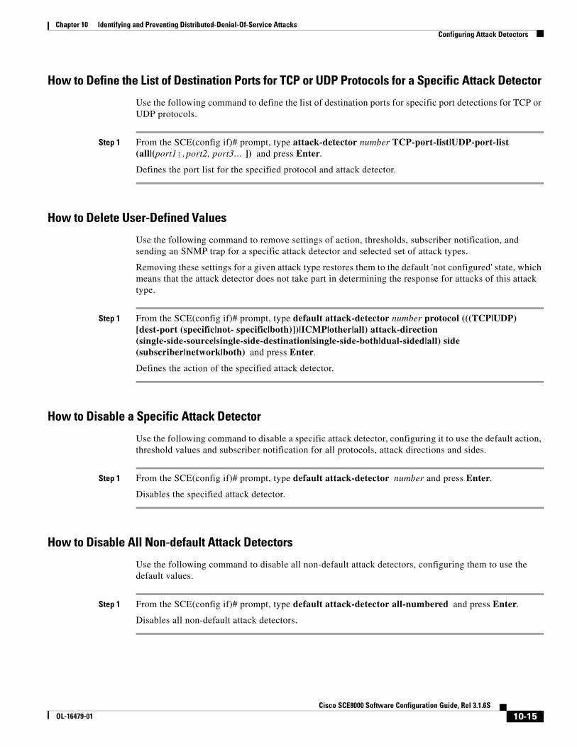
Chapter 10 Identifying and Preventing Distributed-Denial-Of-Service Attacks Configuring Attack Detectors
How to Define the List of Destination Ports for TCP or UDP Protocols for a Specific Attack Detector
Use the following command to define the list of destination ports for specific port detections for TCP or UDP protocols.
Step 1 From the SCE(config if)# prompt, type attack-detector number TCP-port-list|UDP-port-list (all|(port1[,port2, port3… ]) and press Enter.
Defines the port list for the specified protocol and attack detector.
How to Delete User-Defined Values
Use the following command to remove settings of action, thresholds, subscriber notification, and sending an SNMP trap for a specific attack detector and selected set of attack types.
Removing these settings for a given attack type restores them to the default 'not configured' state, which means that the attack detector does not take part in determining the response for attacks of this attack type.
Step 1 From the SCE(config if)# prompt, type default attack-detector number protocol (((TCP|UDP) [dest-port (specific|not- specific|both)])|ICMP|other|all) attack-direction (single-side-source|single-side-destination|single-side-both|dual-sided|all) side (subscriber|network|both) and press Enter.
Defines the action of the specified attack detector.
How to Disable a Specific Attack Detector
Use the following command to disable a specific attack detector, configuring it to use the default action, threshold values and subscriber notification for all protocols, attack directions and sides.
Step 1 From the SCE(config if)# prompt, type default attack-detector number and press Enter.
Disables the specified attack detector.
How to Disable All Non-default Attack Detectors
Use the following command to disable all non-default attack detectors, configuring them to use the default values.
Step 1 From the SCE(config if)# prompt, type default attack-detector all-numbered and press Enter.
Disables all non-default attack detectors.
10-15Cisco SCE8000 Software Configuration Guide, Rel 3.1.6S
OL-16479-01

Chapter 10 Identifying and Preventing Distributed-Denial-Of-Service Attacks Configuring Attack Detectors
How to Disable All Attack Detectors
Use the following command to disable all attack detectors, configuring them to use the default values.
Step 1 From the SCE(config if)# prompt, type default attack-detector all and press Enter.
Disables all attack detectors.
Sample Attack Detector ConfigurationThe following configuration changes the default user threshold values used for detecting ICMP attacks, and configures an attack-detector with high thresholds for UDP attacks, preventing false detections of two DNS servers (10.1.1.10 and 10.1.1.13) as being attacked.
Step 1 From the SCE(config)# prompt, type interface linecard 0 and press Enter.
Enters linecard interface configuration mode
Step 2 From the SCE(config if)# prompt, type attack-detector default protocol ICMP attack-direction single-side-source side both action report open-flow-rate 1000 suspected-flows-rate 100 suspected-flows-ratio 10 and press Enter.
Configures the default ICMP threshold and action.
Step 3 From the SCE(config if)# prompt, type attack-detector 1 access-list 3 comment "DNS servers" and press Enter.
Enables attack detector #1 and assigns ACL #3 to it.
Step 4 From the SCE(config if)# prompt, type attack-detector 1 UDP-ports-list 53
Defines the list of UDP destination ports for attack detector #1 with one port, port 53
Step 5 From the SCE(config if)# prompt, type attack-detector 1 protocol UDP dest-port specific attack-direction single-side-destination side both action report open-flow-rate 1000000 suspected-flows-rate 1000000 and press Enter.
Defines the thresholds and action for attack detector #1.
Step 6 From the SCE(config if)# prompt, type attack-detector 1 protocol UDP dest-port specific attack-direction single-side-destination side subscriber notify-subscriber and press Enter.
Enables subscriber notification for attack detector #1.
Step 7 From the SCE(config if)# prompt, type exit and press Enter.
Exits the linecard interface configuration mode.
Step 8 Configure ACL #3, which has been assigned to the attack detector.
SCE(config)# access-list 3 permit 10.1.1.10 SCE(config)# access-list 3 permit 10.1.1.13
10-16Cisco SCE8000 Software Configuration Guide, Rel 3.1.6S
OL-16479-01

Chapter 10 Identifying and Preventing Distributed-Denial-Of-Service Attacks Subscriber Notifications
Subscriber Notifications • Configuring the Subscriber Notification Port, page 10-17
• How to Remove the Subscriber Notification Port, page 10-17
Subscriber notification is a capability used- for notifying a subscriber in real-time about current attacks involving IP addresses mapped to that subscriber. Subscriber notification is configured on a per-attack-detector level, as explained above, and must also be enabled and configured by the application loaded to the SCE platform, as explained in the appropriate Service Control Application user guide.
In the current solutions, the SCE Platform notifies the subscriber about the attack by redirecting HTTP flows originating from the subscriber to the service provider’s server, that should notify the subscriber that he is under attack. This raises a question regarding TCP attacks originating from the subscriber that are configured with block action. Such attacks cannot normally be notified to the subscriber using HTTP redirection, since all HTTP flows originating from the subscriber are TCP flows, and they are therefore blocked along with all other attack flows. To enable effective use of HTTP redirect, there is a CLI command that prevents blocking of TCP flows originating from the subscriber to a specified TCP port, even when the above scenario occurs.
Configuring the Subscriber Notification Port You can define a port to be used as the subscriber notification port. The attack filter will never block TCP traffic from the subscriber side of the SCE platform to this port, leaving it always available for subscriber notification.
Options
The following option is available:
• portnumber — the number of the port to be used as the subscriber notification port
Step 1 From the SCE(config if)# prompt, type attack-filter subscriber-notification ports portnumber and press Enter.
How to Remove the Subscriber Notification Port
Step 1 From the SCE(config if)# prompt, type no attack-filter subscriber-notification ports and press Enter.
10-17Cisco SCE8000 Software Configuration Guide, Rel 3.1.6S
OL-16479-01

Chapter 10 Identifying and Preventing Distributed-Denial-Of-Service Attacks Preventing and Forcing Attack Detection
Preventing and Forcing Attack Detection • Options, page 10-18
• Preventing Attack Filtering, page 10-19
• Forcing Attack Filtering, page 10-19
After configuring the attack detectors, the SCE platform automatically detects attacks and handles them according to the configuration. However, there are scenarios in which a manual intervention is desired, either for debug purposes, or because it is not trivial to reconfigure the SCE platform attack-detectors properly. For example:
• The SCE platform has detected an attack, but the user knows this to be a false alarm. The proper action that should be taken by the user is to configure the system with higher thresholds (for the whole IP range, or maybe for specific IP addresses or ports). However, this might take time, and, if attack handling is specified as ‘Block’, the user may wish to stop the block action for this specific attack quickly, leaving the configuration changes for a future time when there is time to plan the needed changes properly.
Use the don't-filter command described below for this type of case.
• An ISP is informed that one of his subscribers is being attacked by a UDP attack from the network side. The ISP wants to protect the subscriber from this attack by blocking all UDP traffic to the subscriber, but unfortunately the SCE platform did not recognize the attack. (Alternatively, it could be that the attack was recognized, but the configured action was ‘report’ and not ‘block’).
Use the force-filter command described below for this type of case.
The user can use the CLI attack filtering commands to do the following:
• Configure a don't-filter command to prevent or stop filtering of an attack related to a specified IP address
• Configure a force-filter command to force filtering (with a specific action) of an attack related to a specified IP address
Use the following commands to either force or prevent attack filtering:
• [no] attack-filter don't-filter
• [no] attack-filter force-filter
OptionsIn addition to the attack detector options described above, the following options are available:
• ip-address — the IP address for which to prevent attack filtering.
If attack -direction is dual-sided, an IP address must be configured for both the source (source-ip-address) and the destination (dest-ip-address) sides.
10-18Cisco SCE8000 Software Configuration Guide, Rel 3.1.6S
OL-16479-01

Chapter 10 Identifying and Preventing Distributed-Denial-Of-Service Attacks Preventing and Forcing Attack Detection
Preventing Attack FilteringAttack filtering can be prevented for a specified IP address and attack type by executing a dont-filter CLI command. If filtering is already in process, it will be stopped. When attack filtering has been stopped, it remains stopped until explicitly restored by another CLI command (either force-filter or no dont-filter).
• How to Configure a dont-filter Setting for a Specified Situation, page 10-19
• How to Remove a dont-filter Setting from a Specified Situation, page 10-19
• How to Remove All dont-filter Settings, page 10-19
How to Configure a dont-filter Setting for a Specified Situation
Step 1 From the SCE(config if)# prompt, type attack-filter dont-filter protocol (((TCP|UDP) [dest-port (port-number |not-specific))|ICMP|other) attack-direction (((single-side-source|single-side-destination|single-side-both) (ip ip-address)|(dual-sided source-ip source-ip-address destination-ip dest-ip-address)) side (subscriber|network|both) and press Enter.
How to Remove a dont-filter Setting from a Specified Situation
Step 1 From the SCE(config if)# prompt, type no attack-filter dont-filter protocol (((TCP|UDP) [dest-port (port-number |not-specific))|ICMP|other) attack-direction (((single-side-source|single-side-destination|single-side-both) (ip ip-address)|(dual-sided source-ip source-ip-address destination-ip dest-ip-address)) side (subscriber|network|both) and press Enter.
How to Remove All dont-filter Settings
Step 1 From the SCE(config if)# prompt, type no attack-filter dont-filter all and press Enter.
Forcing Attack FilteringAttack filtering can be forced for a specified IP address/protocol. If filtering is already in process, it will be stopped. Forced attack filtering will continue until undone by an explicit CLI command (either no force-filter or dont-filter).
• How to Configure a force-filter Setting for a Specified Situation, page 10-20
• How to Remove a force-filter Setting from a Specified Situation, page 10-20
• How to Remove All force-filter Settings, page 10-20
10-19Cisco SCE8000 Software Configuration Guide, Rel 3.1.6S
OL-16479-01

Chapter 10 Identifying and Preventing Distributed-Denial-Of-Service Attacks Monitoring Attack Filtering
How to Configure a force-filter Setting for a Specified Situation
Step 1 From the SCE(config if)# prompt, type attack-filter force-filter protocol (((TCP|UDP) [dest-port (port-number |not-specific))|ICMP|other) attack-direction (((single-side-source|single-side-destination|single-side-both) (ip ip-address)|(dual-sided source-ip source-ip-address destination-ip dest-ip-address)) side (subscriber|network|both)[notify-subscriber] and press Enter.
How to Remove a force-filter Setting from a Specified Situation
Step 1 From the SCE(config if)# prompt, type no attack-filter force-filter protocol (((TCP|UDP) [dest-port (port-number |not-specific))|ICMP|other) attack-direction (((single-side-source|single-side-destination|single-side-both) (ip ip-address)|(dual-sided source-ip source-ip-address destination-ip dest-ip-address)) side (subscriber|network|both) and press Enter.
How to Remove All force-filter Settings
Step 1 From the SCE(config if)# prompt, type no attack-filter force-filter all and press Enter.
Monitoring Attack Filtering • Monitoring Attack Filtering Using SNMP Traps, page 10-20
• Monitoring Attack Filtering Using CLI Commands, page 10-22
• Viewing the Attack Log, page 10-28
There are three options for monitoring attack filtering and detection:
• CLI show commands
• SNMP attack detection traps
• Attack log
Monitoring Attack Filtering Using SNMP TrapsThe system sends a trap at the start of a specific attack detection event, and also when a specific detection event ends, as follows:
• STARTED_FILTERING trap – String with the attack information
• STOPPED_FILTERING
– String with the attack information
– String with the reason for stopping
10-20Cisco SCE8000 Software Configuration Guide, Rel 3.1.6S
OL-16479-01

Chapter 10 Identifying and Preventing Distributed-Denial-Of-Service Attacks Monitoring Attack Filtering
The format of the attack-information string sent when an attack begins is:
• If attack was detected in the traffic:
Attack detected: Attack 'IP-info> from 'side> side, protocol 'protocol>. 'rate1>open flows per second detected, 'rate2' Ddos-suspected flows per second detected. Action is: 'action'.
• If attack was declared as a result of a force-filter command:
Attack Filter: Forced 'forced-action' 'IP-info' from 'side' side, protocol 'protocol'. Attack forced using a force-filter command.
The format of the attack-information string sent when an attack ends is:
• If attack was detected in the traffic:
End-of-attack detected: Attack 'IP-info' from 'side' side, protocol 'protocol'. Action is: 'action' Duration 'duration' seconds, 'total-flows' 'hw-filter'
• If the end of the attack was declared as a result of a no force-filter command or a new don't-filter command:
Attack Filter: Forced to end 'action2' 'IP-info' from 'side' side, protocol 'protocol'. Attack end forced using a 'no force-filter' or a 'don't-filter' command.
The format of the reason string sent when an attack begins is:
• If attack end was detected in the traffic:
Detected attack end
• If the end of the attack was declared as a result of a no force-filter command or a new don't-filter command:
Forced attack end
Following are the possible values that may appear in the fields indicated in the information strings (''):
• 'action'
– Report
– Block
• 'forced-action' is one of the following values, depending on the configured force-filter action.
– block of flows
– report
• 'IP-info' is in one of the following formats, depending on the direction of the attack, and whether one or two IP addresses were detected
– from IP address A.B.C.D
– on IP address A.B.C.D
– from IP address A.B.C.D to IP address A.B.C.D
• 'side'
– subscriber
– network
10-21Cisco SCE8000 Software Configuration Guide, Rel 3.1.6S
OL-16479-01

Chapter 10 Identifying and Preventing Distributed-Denial-Of-Service Attacks Monitoring Attack Filtering
• 'protocol'
– TCP
– UDP
– ICMP
– other
• 'rate1' and 'rate2' are numbers
• 'duration' is a number.
• 'total-flows' is one of the following strings, depending on the attack action:
– If 'action' is block: 'number' flows blocked.
– If 'action' is report: attack comprised of 'number' flows.
• 'hw-filter'
– If the attack was not filtered by a hardware filter: empty string
– If the attack was filtered by a hardware filter: HW filters used, actual attack duration is probably smaller than reported above, actual amount of flows handled is probably larger than reported above.
Monitoring Attack Filtering Using CLI Commands • How to display a specified attack detector configuration, page 10-23
• How to display the default attack detector configuration, page 10-24
• How to display all attack detector configurations, page 10-25
• How to display filter state (enabled or disabled), page 10-25
• How to display configured threshold values and actions, page 10-25
• How to display the current counters, page 10-27
• How to display all currently handled attacks, page 10-27
• How to display all existing force-filter settings, page 10-27
• How to display all existing don't-filter settings, page 10-27
• How to display the list of ports selected for subscriber notification, page 10-27
• How to find out whether hardware attack filtering has been activated, page 10-28
Use these commands to monitor attack detection and filtering:
• show interface linecard 0 attack-detector
• show interface linecard 0 attack-filter
• show interface linecard 0 attack-filter query
• show interface linecard 0 attack-filter current-attacks
• show interface linecard 0 attack-filter don't-filter
• show interface linecard 0 attack-filter force-filter
• show interface linecard 0 attack-filter subscriber-notification ports
10-22Cisco SCE8000 Software Configuration Guide, Rel 3.1.6S
OL-16479-01

Chapter 10 Identifying and Preventing Distributed-Denial-Of-Service Attacks Monitoring Attack Filtering
How to display a specified attack detector configuration
• Options, page 10-23
• Example, page 10-23
The following information is displayed:
• Protocol Side — Whether the attack detector applies to attacks originating at the subscriber or network side.
• Direction — Whether the attack detector applies to single sided or dual sided attacks. Action to take if an attack is detected.
• Thresholds:
– open-flows-rate — Default threshold for rate of open flows (new open flows per second).
– suspected-flows-rate — Default threshold for rate of suspected DDoS flows (new suspected flows per second).
– suspected-flows-ratio — Default threshold for ratio of suspected flow rate to open flow rate.
• Subscriber notification — enabled or disabled.
• Alarm: sending an SNMP trap enabled or disabled.
Options
The following option is available:
• number — the number of the attack detector to display
Step 1 From the SCE> prompt, type show interface linecard 0 attack-detector number and press Enter.
Example SCE>show interface LineCard 0 attack-detector 1 Detector #1: Comment: 'Sample' Access-list: 1 Effective only for TCP port(s) 21,23,80 Effective for all UDP ports Protocol|Side|Direction ||Action| Thresholds |Sub- |Alarm
| | || |Open flows|Ddos-Suspected flows|notif| | | || |rate |rate |ratio | |
--------|----|-----------||------|----------|------------|-------|-----|----- TCP |net.|source-only|| | | | | | TCP |net.|dest-only || | | | | | TCP |sub.|source-only|| | | | | | TCP |sub.|dest-only || | | | | | TCP |net.|source+dest|| | | | | | TCP |sub.|source+dest|| | | | | | TCP+port|net.|source-only||Block | | | | |Yes TCP+port|net.|dest-only || | | | | | TCP+port|sub.|source-only||Block | | | | |Yes TCP+port|sub.|dest-only || | | | | | TCP+port|net.|source+dest|| | | | | | TCP+port|sub.|source+dest|| | | | | | UDP |net.|source-only|| | | | | | UDP |net.|dest-only || | | | | | UDP |sub.|source-only|| | | | | | UDP |sub.|dest-only || | | | | |
10-23Cisco SCE8000 Software Configuration Guide, Rel 3.1.6S
OL-16479-01

Chapter 10 Identifying and Preventing Distributed-Denial-Of-Service Attacks Monitoring Attack Filtering
UDP |net.|source+dest|| | | | | | UDP |sub.|source+dest|| | | | | | UDP+port|net.|source-only|| | | | | | UDP+port|net.|dest-only || | | | | | UDP+port|sub.|source-only|| | | | | | UDP+port|sub.|dest-only || | | | | | UDP+port|net.|source+dest|| | | | | | UDP+port|sub.|source+dest|| | | | | | ICMP |net.|source-only|| | | | | | ICMP |net.|dest-only || | | | | | ICMP |sub.|source-only|| | | | |Yes | ICMP |sub.|dest-only || | | | | | other |net.|source-only|| | | | | | other |net.|dest-only || | | | | | other |sub.|source-only|| | | | | | other |sub.|dest-only || | | | | | Empty fields indicate that no value is set and configuration from the default attack detector is used. SCE#>
How to display the default attack detector configuration
Step 1 From the SCE> prompt, type show interface linecard 0 attack-detector default and press Enter.
Example SCE>show interface LineCard 0 attack-detector default Default detector: Protocol|Side|Direction ||Action| Thresholds |Sub- |Alarm
| | || |Open flows|Ddos-Suspected flows|notif| | | || |rate |rate |ratio | |
--------|----|-----------||------|----------|------------|-------|-----|----- TCP |net.|source-only||Report| 1000| 500|50 |No |No TCP |net.|dest-only ||Report| 1000| 500|50 |No |No TCP |sub.|source-only||Report| 1000| 500|50 |No |No TCP |sub.|dest-only ||Report| 1000| 500|50 |No |No TCP |net.|source+dest||Report| 100| 50|50 |No |No TCP |sub.|source+dest||Report| 100| 50|50 |No |No TCP+port|net.|source-only||Report| 1000| 500|50 |No |No TCP+port|net.|dest-only ||Report| 1000| 500|50 |No |No TCP+port|sub.|source-only||Report| 1000| 500|50 |No |No TCP+port|sub.|dest-only ||Report| 1000| 500|50 |No |No TCP+port|net.|source+dest||Report| 100| 50|50 |No |No TCP+port|sub.|source+dest||Report| 100| 50|50 |No |No UDP |net.|source-only||Report| 1000| 500|50 |No |No UDP |net.|dest-only ||Report| 1000| 500|50 |No |No UDP |sub.|source-only||Report| 1000| 500|50 |No |No UDP |sub.|dest-only ||Report| 1000| 500|50 |No |No UDP |net.|source+dest||Report| 100| 50|50 |No |No UDP |sub.|source+dest||Report| 100| 50|50 |No |No UDP+port|net.|source-only||Report| 1000| 500|50 |No |No UDP+port|net.|dest-only ||Report| 1000| 500|50 |No |No UDP+port|sub.|source-only||Report| 1000| 500|50 |No |No UDP+port|sub.|dest-only ||Report| 1000| 500|50 |No |No UDP+port|net.|source+dest||Report| 100| 50|50 |No |No UDP+port|sub.|source+dest||Report| 100| 50|50 |No |No ICMP |net.|source-only||Report| 500| 250|50 |No |No ICMP |net.|dest-only ||Report| 500| 250|50 |No |No ICMP |sub.|source-only||Report| 500| 250|50 |No |No ICMP |sub.|dest-only ||Report| 500| 250|50 |No |No
10-24Cisco SCE8000 Software Configuration Guide, Rel 3.1.6S
OL-16479-01

Chapter 10 Identifying and Preventing Distributed-Denial-Of-Service Attacks Monitoring Attack Filtering
other |net.|source-only||Report| 500| 250|50 |No |No other |net.|dest-only ||Report| 500| 250|50 |No |No other |sub.|source-only||Report| 500| 250|50 |No |No other |sub.|dest-only ||Report| 500| 250|50 |No |No SCE#>
How to display all attack detector configurations
Step 1 From the SCE> prompt, type show interface linecard 0 attack-detector all and press Enter.
How to display filter state (enabled or disabled)
Step 1 From the SCE> prompt, type show interface linecard 0 attack-filter and press Enter.
Example SCE>show interface LineCard 0 attack-filter Enabled state: ------------------ Protocol |Direction |State ----------|------------|------------ TCP |source-only |enabled TCP |dest-only |enabled TCP |dest+source |enabled TCP+port |source-only |enabled TCP+port |dest-only |enabled TCP+port |dest+source |enabled UDP |source-only |enabled UDP |dest-only |enabled UDP |dest+source |enabled UDP+port |source-only |enabled UDP+port |dest-only |enabled UDP+port |dest+source |enabled ICMP |source-only |enabled ICMP |dest-only |enabled other |source-only |enabled other |dest-only |enabled SCE#>
How to display configured threshold values and actions
Use this command to display the configured threshold values and actions a specified IP address (and port), taking into account the various specific attack detector access list configurations
Options
In addition to the attack detector options described above, the following options are available:
• ip-address — the IP address for which to display information.
If attack -direction is dual-sided, an IP address must be configured for both the source (source-ip-address) and the destination (dest-ip-address) sides.
• portnumber — the port number for which to display information.
10-25Cisco SCE8000 Software Configuration Guide, Rel 3.1.6S
OL-16479-01

Chapter 10 Identifying and Preventing Distributed-Denial-Of-Service Attacks Monitoring Attack Filtering
Step 1 From the SCE> prompt, type show interface linecard 0 attack-filter query ((single-sided ip ip-address)|(dual-sided source-IP source-ip-address destination-IP dest-ip-address)) [dest-port portnumber] configured and press Enter.
Examples
Example 1
This example shows a query for a single IP address.
SCE#>show interface linecard 0 attack-filter query single-sided ip 10.1.1.1 configured Protocol|Side|Dir.|Action| Thresholds |don't- |force-|Sub- |Alarm
| | | |Open flows|Ddos-Susp. flows|filter|filter|notif| | | | |rate |rate |ratio| | | |
--------|----|----|------|----------|----------|-----|----- |------|-----|----- TCP |net.|src.|Report| 1000| 500| 50|No |No | No| No TCP |net.|dst.|Report| 1000| 500| 50|No |No | No| No TCP |sub.|src.|Report| 1000| 500| 50|No |No | No| No TCP |sub.|dst.|Report| 1000| 500| 50|No |No | No| No UDP |net.|src.|Report| 1000| 500| 50|No |No | No| No UDP |net.|dst.|Report| 1000| 500| 50|No |No | No| No UDP |sub.|src.|Report| 1000| 500| 50|No |No | No| No UDP |sub.|dst.|Report| 1000| 500| 50|No |No | No| No ICMP |net.|src.|Report| 500| 250| 50|No |No | No| No ICMP |net.|dst.|Report| 500| 250| 50|No |No | No| No ICMP |sub.|src.|Report| 500| 250| 50|No |No | Yes| No | | | | | | | | | (1)| ICMP |sub.|dst.|Report| 500| 250| 50|No |No | No| No other |net.|src.|Report| 500| 250| 50|No |No | No| No other |net.|dst.|Report| 500| 250| 50|No |No | No| No other |sub.|src.|Report| 500| 250| 50|No |No | No| No other |sub.|dst.|Report| 500| 250| 50|No |No | No| No (N) below a value means that the value is set through attack-detector #N. SCE#>
Example 2
This example shows a query for a single IP address, with a specified port.
SCE#>show interface linecard 0 attack-filter query single-sided ip 10.1.1.1 dest-port 21 configured Protocol|Side|Dir.|Action| Thresholds |don't- |force-|Sub- |Alarm
| | | |Open flows|Ddos-Susp. flows|filter|filter|notif| | | | |rate |rate |ratio| | | |
--------|----|----|------|----------|----------|-----|----- |------|-----|----- TCP+port|net.|src.|Block | 1000| 500| 50|No |No | No| Yes | | |(1) | | | | | | | (1) TCP+port|net.|dst.|Report| 1000| 500| 50|No |No | No| No TCP+port|sub.|src.|Block | 1000| 500| 50|No |No | No| Yes | | |(1) | | | | | | | (1) TCP+port|sub.|dst.|Report| 1000| 500| 50|No |No | No| No UDP+port|net.|src.|Report| 1000| 500| 50|No |No | No| No UDP+port|net.|dst.|Report| 1000| 500| 50|No |No | No| No UDP+port|sub.|src.|Report| 1000| 500| 50|No |No | No| No UDP+port|sub.|dst.|Report| 1000| 500| 50|No |No | No| No (N) below a value means that the value is set through attack-detector #N. SCE#>
10-26Cisco SCE8000 Software Configuration Guide, Rel 3.1.6S
OL-16479-01

Chapter 10 Identifying and Preventing Distributed-Denial-Of-Service Attacks Monitoring Attack Filtering
How to display the current counters
Use this command to display the current counters for the specified attack detector for attack types for a specified IP address.
Step 1 From the SCE> prompt, type show interface linecard 0 attack-filter query ((single-sided ip ip-address)|(dual-sided source-IP source-ip-address destination-IP dest-ip-address)) [dest-port portnumber] current and press Enter.
How to display all currently handled attacks
Step 1 From the SCE> prompt, type show interface linecard 0 attack-filter current-attacks and press Enter.
How to display all existing force-filter settings
Step 1 From the SCE> prompt, type show interface linecard 0 attack-filter force-filter and press Enter.
How to display all existing don't-filter settings
Step 1 From the SCE> prompt, type show interface linecard 0 attack-filter dont-filter and press Enter.
How to display the list of ports selected for subscriber notification
Step 1 From the SCE> prompt, type show interface linecard 0 attack-filter subscriber-notification ports and press Enter.
10-27Cisco SCE8000 Software Configuration Guide, Rel 3.1.6S
OL-16479-01

Chapter 10 Identifying and Preventing Distributed-Denial-Of-Service Attacks Monitoring Attack Filtering
How to find out whether hardware attack filtering has been activated
Step 1 From the SCE> prompt, type show interface linecard 0 attack-filter current-attacks and press Enter.
In the output from this command, look for the "HW-filter" field. If this field is "yes", the user must take into account the probable inaccuracies in the attack reporting.
Note This information also appears in the attack log file.
---|---------------|-----------|------------|----------|------|------|------ ---|Source IP -----|Side / |Open rate / |Handled |Action|HW- |force- ---| Dest IP|Protocol |Susp. rate | flows / | |filter|filter ---| |Duration | | | ---|---------------|-----------|------------|----------|------|------|------
|10.1.1.1 |Subscriber| 523| 4045|Report|No |No | *|TCP | 0| 9| | |
---|----------------|-----------|------------|------------|------|------|-------
Viewing the Attack Log • The Attack Log, page 10-28
• How to View the Attack Log, page 10-29
• How to Copy the Attack Log to a File, page 10-29
The Attack Log
The attack-log contains a message for each specific-IP detection of attack beginning and attack end. Messages are in CSV format.
The message for detecting attack beginning contains the following data:
• IP address (Pair of addresses, if detected)
• Protocol Port number (If detected)
• Attack-direction (Attack-source or Attack-destination)
• Interface of IP address (subscriber or network)
• Open-flows-rate, suspected-flows-rate and suspected-flows-ratio at the time of attack detection
• Threshold values for the detection
• Action taken
The message for detecting attack end contains the following data:
• IP address (Pair of addresses, if detected)
• Protocol Port number (If detected)
• Attack-direction (Attack-source or Attack-destination)
• Interface of IP address
• Number of attack flows reported/blocked
10-28Cisco SCE8000 Software Configuration Guide, Rel 3.1.6S
OL-16479-01

Chapter 10 Identifying and Preventing Distributed-Denial-Of-Service Attacks Monitoring Attack Filtering
• Action taken
As with other log files, there are two attack log files. Attack events are written to one of these files until it reaches maximum capacity, at which point the events logged in that file are then temporarily archived. New attack events are then automatically logged to the alternate log file. When the second log file reaches maximum capacity, the system then reverts to logging events to the first log file, thus overwriting the temporarily archived information stored in that file.
The following SNMP trap indicates that the attack log is full and a new log file has been opened
ST_LINE_ATTACK_LOG_IS_FULL
Note When the attack log is large, it is not recommended to display it. Copy a large log to a file to view it.
How to View the Attack Log
Step 1 From the SCE# prompt, type more line-attack-log and press Enter.
How to Copy the Attack Log to a File
Step 1 From the SCE# prompt, type more line-attack-log redirect filename and press Enter.
Writes the log information to the specified file.
10-29Cisco SCE8000 Software Configuration Guide, Rel 3.1.6S
OL-16479-01

Chapter 10 Identifying and Preventing Distributed-Denial-Of-Service Attacks Monitoring Attack Filtering
10-30Cisco SCE8000 Software Configuration Guide, Rel 3.1.6S
OL-16479-01

CiscOL-16479-01
C H A P T E R 11
Managing the SCMPThis module provides an overview of the Service Control Management Protocol (SCMP) capabilities. It also explains the various procedures for configuring and monitoring SCMP.
• About SCMP, page 11-1
• Configuring the SCMP, page 11-6
• Monitoring the SCMP Environment, page 11-13
About SCMPThe Service Control Management Protocol (SCMP) is a protocol that integrates the SCE platform and the ISG (Intelligent Service Gateway) functionality of the Cisco routers, thereby providing a mechanism that allows the ISG and the SCE platform to manage subscriber sessions together without requiring coordination and orchestration by additional components.
• SCMP Terminology, page 11-2
• Deployment Scenarios, page 11-3
• SCMP Peer Devices, page 11-4
• SCMP Subscriber Management, page 11-6
The SCMP is a Cisco proprietary protocol that uses the RADIUS protocol with CoA (Change of Authorization) support as a transport layer. The SCMP provides connection management messages, subscriber management and subscriber accounting messages. Each subscriber in the SCE platform represents a session in the SCMP peer (as defined by the ISG terminology).
Connection management
The SCE platform initiates the connection to the peer device. On SCMP connection establishment, the SCE platform and ISG negotiate the following details:
• Introduction mode – whether the SCMP peer must send a session-provisioning message on session creation.
• Keep-alive message interval
• Protocol version
11-1o SCE8000 Software Configuration Guide, Rel 3.1.6S

Chapter 11 Managing the SCMP About SCMP
Subscriber Management
The SCMP peers can work in either of two introduction modes. These introduction modes affect only how and when a session is created on the SCE platform:
• The SCMP peer provisions the session to the SCE platform when it is created in the peer device (push)
• The SCE platform queries the SCMP peer regarding unmapped IP traffic (pull).
The SCMP uses queries as a backup to the push introduction mode, to be robust to issues such as networking problems and SCE platform reboot.
In addition to session creation, the SCMP supports the following operations:
• Change of session policy and network IDs using the update-session message
• Removal of the session when the user logs-out
• Activate-policy, which changes the session policy
• Deactivate-policy, which sets the policy value of the related anonymous-group template (based on the session manager)
Subscriber Accounting
On session creation, the SCE platform sends an accounting start message for the session and on logout, it sends an accounting stop message for the session. In addition, for each SCA BB service-counter an accounting-session is maintained (start, interim and stop messages), which provides information regarding the relevant volume, flow-count and duration.
The accounting messages are based on the new Subscriber-Accounting RDR and are sent according to the interval defined in the PQB configuration.
SCMP TerminologySCMP terminology is similar to, but not identical to, existing SCE platform terminology. It is derived from the ISG terminology, since every SCE subscriber is actually an ISG session.
• subscriber – The client who is purchasing service from the Service Provider and is receiving the bill.
• User – A member, employee or guest at the subscriber household or business using the service.
• Session – A logically identifiable entity on the service gateway that represents communication with a peer. It is based on a unique combination of one or more Identity Keys such as an IP address, a subnet, a MAC address, a tunnel termination interface (PPP) or a port.
Each session is assigned a unique identifier.
• Flow – Characterized by several parameters identifiable from the traffic such as source IP address, destination IP address, source port, destination port, protocol and in some cases direction.
• SCMP Peer – A Cisco device running IOS with the ISG module enabled.
• Identity Key – One of the keys that help identify a Session. The identity keys that are relevant to the SCE-ISG control-bus are:
– IP Address/Subnet
– IP Subnet
• Policy – Defines all aspects of subscriber session processing. A policy consists of conditions and actions. Traffic conditions will classify traffic and allow policing actions to be applied to the traffic. Policies may be provisioned, updated and removed. Policies may also be activated for a session or deactivated for a session. A policy may be referred to by name.
11-2Cisco SCE8000 Software Configuration Guide, Rel 3.1.6S
OL-16479-01

Chapter 11 Managing the SCMP About SCMP
Deployment ScenariosThe following sections illustrate the basic types of SCMP deployment scenarios.
• 1xISG – 1xSCE
• NxISG – MxSCE Via Load Balancing (MGSCP)
Single ISG Router with a Single SCE Platform (1xISG – 1xSCE)
The following diagram illustrates a deployment using one ISG router with a single SCE platform.
Figure 11-1 Single ISG Router with a Single SCE Platform
Note • The red dotted lines depict the control path communication.
• A deployment of this type might be used with ISG running on a service gateway or BRAS terminating a large number of subscribers. However, note that deploying only one SCE platform results in a single point of failure, which is not generally acceptable in an actual deployment.
2102
64
Internet
Ethernet orATM switch
ISGc10K BRAS
DSLAM CPE
PPP session
DRI
PC
SCE
Policyserver
AAA / policydatabase Control
protocol
11-3Cisco SCE8000 Software Configuration Guide, Rel 3.1.6S
OL-16479-01

Chapter 11 Managing the SCMP About SCMP
Multiple ISG Routers with Multiple SCE Platforms via Load Balancing (NxISG – MxSCE)
The following diagram illustrates a deployment using multiple ISG routers with multiple SCE platforms via load balancing. This is the scenario required for a MGSCP deployment.
Figure 11-2 Multiple ISG Routers with Multiple SCE Platforms via Load Balancing
This scenario includes several SCE platforms connected to a Cisco 7600 router. For efficient control of subscriber flows, the same SCE platform must process both directions of each subscriber flow, since the SCE platform keeps the subscriber context. The Cisco 7600 router to which the SCE platforms are connected acts as a dispatching element, distributing subscriber flows between SCE platforms and guaranteeing that all flows of a specific subscriber will pass through the same SCE platform.
This scenario assumes that one (or sometimes more) of the devices in the cluster is redundant.
Note • An ISG device cannot push sessions to two SCE platforms at the same time.
• You must configure multiple SCE platforms with load-balancing (MGSCP) to work in pull integration mode.
SCMP Peer DevicesAn SCMP peer device is a Cisco device running IOS with the ISG module enabled. The SCE platform supports the ability to communicate with several SCMP peer devices at the same time. However, each peer device manages its own subscribers and the corresponding subscriber network IDs. The SCE platform recognizes which subscribers belong to which peer device. There are two mechanisms that accomplish this:
• Login operation
Each SCMP peer device is assigned a unique ID called the Manager-Id. This ID is attached to each subscriber from the moment it is created in the subscriber database, based on the SCMP peer that logged-in the subscriber.
2102
67
PE-1(GSR)
OC-48POS
OC-48POS
BB-2(GSR)
EX-1(GSR)
OC-48POS
OC-192
BB-1(GSR)
Mega Pop
BRAS
SBC-IS Mini Pop
DB-1(GSR/7500)
DB-2(GSR/7500)
DIST-1(6500)
DIST-2(6500)
PE-1(GSR)
DED-1(GSR/7500)
SCE
BRAS
SBC-IS Mini Pop
DB-1(GSR/7500)
DB-2(GSR/7500)
DIST-1(6500)
DIST-2(6500)
PE-1(GSR)
DED-1(GSR/7500)
SCE
SBC IS core network
Core-1(GSR)
Core-1(GSR)
Core-3(GSR)
Core-2(GSR)
OC-192
OC-192
BB-1(GSR)
BB-2(GSR)
11-4Cisco SCE8000 Software Configuration Guide, Rel 3.1.6S
OL-16479-01

Chapter 11 Managing the SCMP About SCMP
• Anonymous groups
An anonymous group is a specified IP range, possibly assigned a subscriber template (see Anonymous Groups and Subscriber Templates, page 9-4.)
SCMP associates each SCMP peer device with at least one anonymous group. SCMP generates subscribers for this anonymous group when it detects traffic from the SCMP peer device that is not mapped to any subscriber. SCMP assigns the SCMP peer manager-Id to this generated anonymous-subscriber. If you have assigned a subscriber template to the group, the anonymous subscribers generated have properties as defined by that template. If you have not assigned a subscriber template, the default template is used.
One SCE platform supports a maximum of 20 SCMP peer devices.
Connection Management
The SCMP attempts to maintain an open connection to each peer device.
The following figure illustrates the SCMP connection state functionality.
Figure 11-3 SCMP Connection State Functionality
The loss-of-sync timeout prevents the SCE platform from retaining sessions that are obsolete and whose identity-keys have been replaced or moved to other sessions thus miss-classification risk is limited.
210263
Notconnected
Connected
Loss-of synch timeout/Remove peer sessions
Not-in-synch
Keep-alive timeout
Connection establishment/Re-query all anonymous
and all introducedsubscribers
Connection establishment/Re-query all anonymous
Keep-alive timeout
Connection establishment/Re-query all anonymous
and all introducedsubscribers
Connection establishment/Re-query all anonymous
11-5Cisco SCE8000 Software Configuration Guide, Rel 3.1.6S
OL-16479-01

Chapter 11 Managing the SCMP Configuring the SCMP
SCMP Subscriber ManagementSubscriber virtualization allows multiple SCMP peer devices to simultaneously manage subscribers in the SCE platform without interfering with each other.
Note Each device must handle a distinct set of subscribers and network IDs.
The following mechanisms support subscriber virtualization:
• SCMP adds the Manager-Id field to each subscriber record in the database.
• All SCMP subscriber provisioning operations include the Manager-Id parameter for each subscriber.
• SCMP performs synchronizations in the context of the Manager-Id.
• SCMP dispatches queries according to the configuration of the anonymous subscriber groups.
GUID and Subscriber ID
The SCMP requires the use of a globally unique identifier (GUID) that is created by and identifies each SCMP peer device. The GUID is a 16-character-long ASCII string. The SCE platform uses the GUID for all communication with the SCMP peer.
SCMP creates the SCE subscriber ID from the concatenation of any or all the following user-related RADIUS attributes, with the GUID as the suffix.
• Calling-Station-Id
• NAS-port-Id
• User-Name
The user defines this subscriber ID structure via CLI.
Configuring the SCMP • Configuring SCMP Parameters, page 11-6
• Adding an SCMP Peer Device, page 11-9
• Deleting Subscribers Managed by an SCMP Peer Device, page 11-11
• Deleting an SCMP Peer Device, page 11-11
• Defining the Subscriber ID, page 11-11
• Configuring the RADIUS Client, page 11-12
Configuring SCMP Parameters • How to Enable the SCMP, page 11-7
• How to Disable the SCMP, page 11-7
• How to Configure the SCMP Peer Device to Push Sessions, page 11-7
• Configuring the SCMP Peer Device to Force Each Subscriber to Single SCE Platform, page 11-8
11-6Cisco SCE8000 Software Configuration Guide, Rel 3.1.6S
OL-16479-01

Chapter 11 Managing the SCMP Configuring the SCMP
• Defining the Keep-alive Interval Parameter, page 11-8
• Defining the Reconnect Interval Parameter, page 11-9
• Defining the Loss-of-Sync Timeout Parameter, page 11-9
You can configure the following options for the SCMP:
• Enable the SCMP
• Configure the SCMP peer device to push sessions to the SCE platform
• Allow the SCMP peer device to provision each subscriber to only one SCE platform.
• Define the SCMP keep-alive interval
• Define the SCMP reconnect interval
• Define the loss-of-sync timeout
• Define the subscriber ID structure
How to Enable the SCMP
By default, the SCMP is disabled.
Step 1 From the SCE(config)# prompt, type scmp and press Enter.
How to Disable the SCMP
Step 1 From the SCE(config)# prompt, type no scmp and press Enter.
How to Configure the SCMP Peer Device to Push Sessions
When SCMP establishes a connection with an SCMP peer device, it informs the device whether the SCMP is configured to push sessions or to wait till the sessions are pulled by the SCE platform.
Use this command to specify push mode. Use the no form of the command to specify pull mode. This configuration takes effect only after the connection is re-established.
Default is disabled (pull mode).
Step 1 From the SCE(config)# prompt, type scmp subscriber send-session-start and press Enter.
How to Disable Pushing Sessions
Use this command to disable pushing sessions to the SCE platform. This means that the SCE platform will pull all sessions from the SCMP peer.
Step 1 From the SCE(config)# prompt, type no scmp subscriber send-session-start and press Enter.
11-7Cisco SCE8000 Software Configuration Guide, Rel 3.1.6S
OL-16479-01

Chapter 11 Managing the SCMP Configuring the SCMP
Configuring the SCMP Peer Device to Force Each Subscriber to Single SCE Platform
When SCMP establishes a connection with an SCMP peer device, it informs the device whether the SCMP is configured to allow each subscriber to be provisioned to only one SCE platform.
Use this command to configure the SCMP peer device to verify that each subscriber is provisioned to only one SCE platform. If a subscriber was provisioned to a different SCE platform, the SCMP removes it from the previous SCE platform and provisions it to the new SCE platform. This configuration is required in MGSCP topology where, if a fail-over between SCE platforms, subscribers might move from one SCE platform to another. If transferred subscribers are not cleared from the previous SCE platform, it can cause capacity issues.
Use the no form of the command to allow SCMP to provision subscribers to more than one SCE platform.
This configuration takes effect only after the connection is re-established.
Default is disabled (subscribers can be provisioned to more than one SCE platform).
Step 1 From the SCE(config)# prompt, type scmp subscriber force-single-sce and press Enter.
How to Disable Forcing Each Subscriber to Single SCE Platform
Use this command to disable forcing each subscriber to only one SCE platform. This allow subscribers to be provisioned to more than one SCE platform.
Step 1 From the SCE(config)# prompt, type no scmp subscriber force-single-sce and press Enter.
Defining the Keep-alive Interval Parameter
The keep-alive interval is the amount of time between keep-alive messages to the SCMP peer device. If the SCMP does not receive a response from the SCMP peer device within the defined interval, the connection is assumed to be down; and the SCMP changes the connection state to false and begins attempts to reconnect.
Options
The following options are available:
• interval — Interval between keep-alive messages from the SCE platform to the SCMP peer device in seconds
– Default = 5 seconds
Step 1 From the SCE(config)# prompt, type scmp keepalive-interval interval and press Enter.
11-8Cisco SCE8000 Software Configuration Guide, Rel 3.1.6S
OL-16479-01

Chapter 11 Managing the SCMP Configuring the SCMP
Defining the Reconnect Interval Parameter
The reconnect interval is the amount of time between attempts by the SCE platform to reconnect with an SCMP peer. The SCE platform attempts to reconnect to the SCMP peer device at the defined intervals by sending an establish-peering-request message.
Options
The following options are available:
• interval — Interval between attempts by the SCE platform to reconnect with an SCMP peer, in seconds
– Default = 30 seconds
Step 1 From the SCE(config)# prompt, type scmp reconnect-interval interval and press Enter.
Defining the Loss-of-Sync Timeout Parameter
The loss of sync timeout interval is the amount of time between loss of connection between the SCE platform and an SCMP peer device and the loss-of-sync event. (To prevent miss-classification, loss-of-sync event removes all subscribers that were provisioned by the relevant SCMP peer device.)
Options
The following options are available:
• interval — Loss of sync timeout interval in seconds
– Default = 90 seconds
Step 1 From the SCE(config)# prompt, type scmp loss-of-sync-timeout interval and press Enter.
Adding an SCMP Peer Device • How to Define an SCMP Peer Device, page 11-10
• How to Assign the SCMP Peer Device to an Anonymous Group, page 11-10
Adding an SCMP peer device is a two-step process:
1. Define the device, configuring the following parameters:
– device name
– RADIUS host
– RADIUS shared secret authorization
– port number (optional)
– accounting port number (optional)
2. Associate the device with one or more unmapped anonymous groups.
11-9Cisco SCE8000 Software Configuration Guide, Rel 3.1.6S
OL-16479-01

Chapter 11 Managing the SCMP Configuring the SCMP
How to Define an SCMP Peer Device
Options
The following options are available:
• peer_device_name — User-assigned name of the SCMP peer device
• radius_hostname — IP address or host-name of the RADIUS host (if a host-name is used, it must be valid at time of the configuration)
• shared_secret — RADIUS shared secret
• auth-portnumber (optional) — authorization port number
• acct-portnumber (optional) — accounting port number
Defaults:
• auth-port# — 1812
• acct-port# — 1813
Step 1 From the SCE(config)# prompt, type scmp name peer_device_name radius radius_hostname secret shared_secret [auth-port auth-portnumber acct-port acct-portnumber] and press Enter.
How to Assign the SCMP Peer Device to an Anonymous Group
This command defines the specified anonymous group to be the IP range of the SCMP peer device. You must define the specified SCMP peer device before assigning the anonymous group.
Options
The following options are available:
• group-name — Name of the anonymous subscriber group to be associated with the specified SCMP peer device.
• range (optional) — IP range defined for the anonymous group
• template (optional) — group template assigned to the anonymous group
• peer-device-name — User-assigned name of the SCMP peer device
Step 1 From the SCE(config if)# prompt, type subscriber anonymous-group name group-name IP-range range [template template] scmp name peer-device-name and press Enter.
How to Remove an Anonymous Group from the SCMP Peer Device
This command defines the specified anonymous group to be the IP range of the SCMP peer device. You must define the specified SCMP peer device before assigning the anonymous group.
Step 1 From the SCE(config if)# prompt, type no subscriber anonymous-group name group-name and press Enter.
11-10Cisco SCE8000 Software Configuration Guide, Rel 3.1.6S
OL-16479-01

Chapter 11 Managing the SCMP Configuring the SCMP
Deleting Subscribers Managed by an SCMP Peer DeviceUse this command to clear all the subscribers that are managed by a specified SCMP peer device.
Options
The following options are available:
• peer_device_name — User-assigned name of the SCMP peer device
Step 1 From the SCE(config if)# prompt, type no subscriber scmp name peer-device-name all and press Enter.
Deleting an SCMP Peer DeviceYou cannot delete an SCMP peer device that has anonymous groups assigned to it. You must remove all associated anonymous groups before deleting the device.
Step 1 First remove all anonymous groups assigned to the device:
SCE(config if)# no subscriber anonymous-group name group-name [IP-range range][template template] scmp name peer-device-name
Step 2 Repeat this step for all anonymous groups assigned to the SCMP peer device.
Step 3 When all anonymous groups have been removed from the device, exit LineCard Interface Configuration mode
SCE(config if)# exit
Step 4 Delete the device
SCE(config)#no scmp name peer_device_name
Defining the Subscriber IDYou can define the structure of the subscriber ID via this command by specifying which of the following elements to include and in which order:
• Calling-Station-Id
• NAS-port-Id
• User-Name
The GUID is always appended at the end of the subscriber ID as defined by this command.
Note You must disable the SCMP interface before executing this command.
11-11Cisco SCE8000 Software Configuration Guide, Rel 3.1.6S
OL-16479-01

Chapter 11 Managing the SCMP Configuring the SCMP
Options
The following options are available:
• 1st element — any one of the following:
– Calling-Station-Id
– NAS-Port-Id
– User-Name
• 2nd element (optional) — any one of the following (if specified, usually not the option specified as the first element):
– Calling-Station-Id
– NAS-Port-Id
– User-Name
• 3rd element (optional) — any one of the following (if specified, usually the remaining option not specified as either of the first two elements):
– Calling-Station-Id
– NAS-Port-Id
– User-Name
Default = no elements concatenated with the GUID
Step 1 Disable the SCMP.
SCE(config)#no scmp
Step 2 Define the subscriber ID:
SCE(config)#scmp subscriber id append-to-guid radius-attributes Calling-Station-Id | NAS-Port-Id | User-Name [Calling-Station-Id | NAS-Port-Id | User-Name] [Calling-Station-Id | NAS-Port-Id | User-Name]
Step 3 Enable the SCMP.
SCE(config)#scmp
Configuring the RADIUS ClientYou can configure the following options for the RADIUS client
• Define the parameters for retransmitting unacknowledged messages.
The RADIUS client polls the sockets to receive the next message and calls the SCMP engine to handle it, based on the type of the received message. Messages that were not acknowledged can be retransmitted up to the configured maximum number of retries.
11-12Cisco SCE8000 Software Configuration Guide, Rel 3.1.6S
OL-16479-01

Chapter 11 Managing the SCMP Monitoring the SCMP Environment
Options
The following options are available:
• times — The maximum number of times the RADIUS client can try unsuccessfully to send a message.
– Default = 3
• timeout (optional) — Timeout interval for retransmitting a message, in seconds
– Default = 1 second
Step 1 From the SCE(config)# prompt, type ip radius-client retry limit times [timeout timeout] and press Enter.
Monitoring the SCMP Environment • How to Monitor the SCMP, page 11-13
• Monitoring the RADIUS Client, page 11-15
You can monitor the following components of the SCMP environment:
• SCMP
• RADIUS client
How to Monitor the SCMP • Options, page 11-13
• How to display the general SCMP configuration, page 11-14
• How to display the configuration all currently defined SCMP peer devices, page 11-14
• How to display the configuration for a specified SCMP peer device, page 11-14
• How to display the statistics for all SCMP peer devices, page 11-14
• How to display the statistics for a specified SCMP peer device, page 11-15
Use the following commands to monitor the SCMP. These commands provide the following information:
• General SCMP configuration
• Configuration of all currently defined SCMP peer devices.
• Configuration of a specified SCMP peer device.
• Statistics for either all SCMP peer devices or a specified SCMP peer device.
Options
The following options are available:
• device-name — The name of the specific SCMP peer device for which to display the configuration or statistics.
11-13Cisco SCE8000 Software Configuration Guide, Rel 3.1.6S
OL-16479-01

Chapter 11 Managing the SCMP Monitoring the SCMP Environment
How to display the general SCMP configuration
Step 1 From the SCE> prompt, type show scmp and press Enter.
Example SCE>show scmp SCMP enabled: yes Keep-alive interval: 5 seconds Loss of synchronization timeout: 90 seconds from disconnection Reconnection interval: 30 seconds Force subscriber on a single SCE: no Peer sends subscriber data on session start Subscriber Id structure: GUID
How to display the configuration all currently defined SCMP peer devices
Step 1 From the SCE> prompt, type show scmp all and press Enter.
How to display the configuration for a specified SCMP peer device
Step 1 From the SCE> prompt, type show scmp name device-name and press Enter.
Example SCE>show scmp name isg SCMP Connection 'isg' status: 10.56.208.91 auth-port 1812 acct-port 1813 Connection state: Connected Peer protocol-version: 1.0 Keep-alive interval: 5 seconds Force single SCE: No Send session start: Yes Time connected: 9 seconds
How to display the statistics for all SCMP peer devices
Step 1 From the SCE> prompt, type show scmp all counters and press Enter.
11-14Cisco SCE8000 Software Configuration Guide, Rel 3.1.6S
OL-16479-01

Chapter 11 Managing the SCMP Monitoring the SCMP Environment
How to display the statistics for a specified SCMP peer device
Step 1 From the SCE> prompt, type show scmp name peer_device_name counters and press Enter.
Example SCE>show scmp name isg counters SCMP Connection 'isg' counters: Total messages sent: 72 Total messages received: 72 Establish requests sent: 1 Establish replies received: 1 Accounting requests sent: 20 Accounting replies received: 20 Subscriber queries sent: 0 Subscriber query response recv: 0 Request retry exceeded: 0 Requests replied with errors: 0 Subscriber requests received: 50 Subscriber responses sent: 50 Failed Requests: 0 Keep-alive sent: 1 Keep-alive received: 1
Monitoring the RADIUS ClientUse the following command to monitor the SCMP RADIUS client. This command displays the general configuration of the RADIUS client.
Step 1 From the SCE> prompt, type show ip radius-client and press Enter.
11-15Cisco SCE8000 Software Configuration Guide, Rel 3.1.6S
OL-16479-01

Chapter 11 Managing the SCMP Monitoring the SCMP Environment
11-16Cisco SCE8000 Software Configuration Guide, Rel 3.1.6S
OL-16479-01

Cisco SCE8000 SOL-16479-01
A
P P E N D I X A Cisco Service Control MIBsThe SCE platform originally supported the standard MIB-II and a proprietary Service Control Enterprise MIB. The proprietary pcube MIB enabled the external management system to perform configuration, performance, troubleshooting and alerting operations specific to the SCE platform that were not provided by the standard MIB.
The proprietary pcube MIBs has been replaced by a combination of standard and Cisco MIBs and new Cisco Service Control MIBs. The new MIB structure was designed to keep backward compatibility and provide the same information as provided in the past as much as possible.
This appendix explains how to map the proprietary pcube MIB supported in previous releases to the new MIB structure. It points out backward compatible issues and provides mapping guidelines from old MIB or OID group to a new MIB.
Note These MIB updates are supported on the SCE8000 platform only. The pcube MIB is backward compatible to 3.1.6 for the SCE 1000 and SCE 2000 platforms.
The list of supported MIBs is described at the following URL under the Cisco Service Routing Products section. Select the desired product and then the desired release.
http://www.cisco.com/public/sw-center/netmgmt/cmtk/mibs.shtml
All Cisco MIBs and some of the common standard MIBs can be obtained at the following URL:
http://tools.cisco.com/Support/SNMP/do/BrowseMIB.do?local=en&step=2
MIB FilesThe pcube MIB was grouped into several MIBs, each of which represented a certain aspect or functionality in the SCE platform (see the tables in the pcube to Cisco MIB Mapping: Detailed OID Mappings, page A-5 section for more details).
The pcube MIB files have been replaced by MIBs from three sources:
• standard MIBs
• existing Cisco MIBs
• new Cisco Service Control MIBs
A-1oftware Configuration Guide, Release 3.1.6S

Appendix A Cisco Service Control MIBs MIB Files
The following tables describe the former pcube MIB files and the MIB files that replace the pcube MIB.
Table A-1 pcube MIBs
MIB Description
PCUBE-SMI.my Defines P-cube enterprise tree structure
PCUBE-PRODUCTS-MIB.my Defines OIDs of Cisco Service Control products
PCUBE-CONFIG-COPY-MIB.my Contains a subset of the Cisco Config-Copy-MIB ported to the pcube enterprise subtree
CISCO-SCAS-BB-MIB.my Contains SCA BB information handlers
PCUBE-SE-MIB.my Contains information about the SCE platform
Table A-2 Standard and Cisco MIBs used to replace pcube MIBs
MIBs Description
CISCO-SMI.my Defines Cisco enterprise tree structure
CISCO-TC.my Contains Textual Conventions needed in some MIBs
CISCO-CONFIG-COPY-MIB.my Facilitates writing of configuration files
CISCO-ENTITY-ALARM-MIB.my Defines the managed objects that support the monitoring of alarms generated by physical entities contained by the system
CISCO-ENTITY-FRU-CONTROL-MIB.my Monitor s and configures operational status of Field Replaceable Units
CISCO-ENTITY-REDUNDANCY-MIB.my Supports configuration, control and monitoring of redundancy protection for various kinds of components on Cisco managed devices.
CISCO-ENTITY-REDUNDANCY-TC-MIB.my Defines the textual conventions used within Cisco Entity Redundancy MIBs
CISCO-ENTITY-SENSOR-MIB.my Monitors the values of sensors in the Entity-MIB
CISCO-PROCESS-MIB.my Provides overall information about the CPU load.
CISCO-QUEUE-MIB.my Manages interface queuing in Cisco devices.
CISCO-SECURE-SHELL-MIB.my Displays and configures accounting and Secure Shell (SSH) related features in a device.
CISCO-SYSLOG-EXT-MIB.my Extends the Cisco Syslog MIB and provides network management support to handle and process Syslog messages as device events
CISCO-SYSLOG-EVENT-EXT-MIB.my Extends the Cisco Syslog.MIB and provides network management support to handle and process Syslog messages as device events
CISCO-SYSLOG-MIB.my Describes and stores the system messages generated by the IOS and any other OS which supports syslogs.
CISCO-TELNET-SERVER-MIB.my Displays and configures Telnet related features in a device.
A-2Cisco SCE8000 Software Configuration Guide, Release 3.1.6S
OL-16479-01
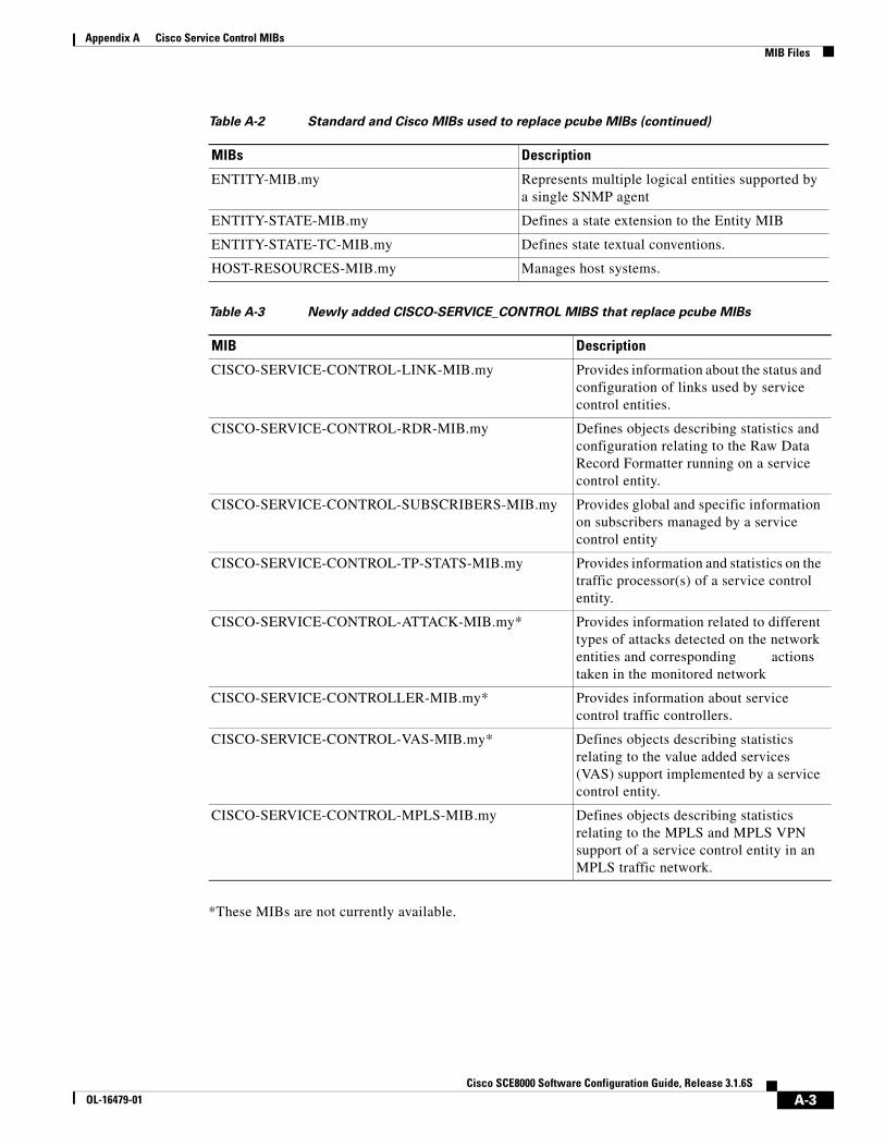
Appendix A Cisco Service Control MIBs MIB Files
*These MIBs are not currently available.
ENTITY-MIB.my Represents multiple logical entities supported by a single SNMP agent
ENTITY-STATE-MIB.my Defines a state extension to the Entity MIB
ENTITY-STATE-TC-MIB.my Defines state textual conventions.
HOST-RESOURCES-MIB.my Manages host systems.
Table A-3 Newly added CISCO-SERVICE_CONTROL MIBS that replace pcube MIBs
MIB Description
CISCO-SERVICE-CONTROL-LINK-MIB.my Provides information about the status and configuration of links used by service control entities.
CISCO-SERVICE-CONTROL-RDR-MIB.my Defines objects describing statistics and configuration relating to the Raw Data Record Formatter running on a service control entity.
CISCO-SERVICE-CONTROL-SUBSCRIBERS-MIB.my Provides global and specific information on subscribers managed by a service control entity
CISCO-SERVICE-CONTROL-TP-STATS-MIB.my Provides information and statistics on the traffic processor(s) of a service control entity.
CISCO-SERVICE-CONTROL-ATTACK-MIB.my* Provides information related to different types of attacks detected on the network entities and corresponding actions taken in the monitored network
CISCO-SERVICE-CONTROLLER-MIB.my* Provides information about service control traffic controllers.
CISCO-SERVICE-CONTROL-VAS-MIB.my* Defines objects describing statistics relating to the value added services (VAS) support implemented by a service control entity.
CISCO-SERVICE-CONTROL-MPLS-MIB.my Defines objects describing statistics relating to the MPLS and MPLS VPN support of a service control entity in an MPLS traffic network.
Table A-2 Standard and Cisco MIBs used to replace pcube MIBs (continued)
MIBs Description
A-3Cisco SCE8000 Software Configuration Guide, Release 3.1.6S
OL-16479-01

Appendix A Cisco Service Control MIBs Loading MIBs
Loading MIBsIt is important to load the MIBs in the proper order.
Before loading any new CISCO-SERVICE-CONTROL MIB, load the following MIBs in this order:
1. SNMPv2-SMI.my
2. SNMPv2-CONF.my
3. SNMPv2-TC.my
4. SNMP-FRAMEWORK-MIB.my
5. ENTITY-MIB.my
6. INET-ADDRESS-MIB.my
7. CISCO-SMI.my
8. CISCO-TC.my
Loading procedure for standard MIBs and other legacy Cisco MIBs is explained here:
http://tools.cisco.com/Support/SNMP/do/BrowseMIB.do?local=en&step=2
pcube to Cisco MIB Mapping This section is an overview of how the former pcube MIB maps to the current Cisco MIBs. Two P-cube MIBs are mapped; PcubeSeMIB and PcubeEngageMIB (CISCO-SCABB-MIB).
Table A-4 Overall tree structure: related objects
Pcube Object Name New MIB Object Name/MIB Name
pcube CISCO-SERVICE-CONTROL or cServiceControl
pcubeProducts ciscoMgmt
pcubeModules Removed
pcubeSeMIB See Table A-5 on page A-4
Table A-5 PcubeSeMIB
PcubeSEMIB Group Name New MIB Object Name/MIB Name
pcubeSeMIBpcubeModuleGroup cServiceControlMIB
pcubeSeConformance cServiceControlNotifs
pcubeSeGroups cServiceControlObjects
pcubeSystemGroup ENTITY and ENTITY-EXTENTION MIBs
pcubeChassisGroup ENTITY and ENTITY-EXTENTION MIBs
pcuebModuleGroup ENTITY and ENTITY-EXTENTION MIBs
pcubeLinkGroup CISCO-SERVICE-CONTROL-LINK-MIB
pcubeDiskGroup HOST-RESOURCES-MIB
A-4Cisco SCE8000 Software Configuration Guide, Release 3.1.6S
OL-16479-01

Appendix A Cisco Service Control MIBs pcube to Cisco MIB Mapping
*These MIBs are not currently available.
Pcube Engage MIB (CISCO-SCA-BB-MIB)The pcubeEnageMIB is currently in the process of being transformed. This MIB will be translated in future releases.
pcube to Cisco MIB Mapping: Detailed OID MappingsThe following tables provide the detailed mappings for specific pcubeSeMIB (1.3.6.1.4.1.5655.4.1/0) OIDs to the current standard and Cisco MIBs.
pcubeRdrFormatterGroup CISCO-SERVICE-CONTROL-RDR-MIB
pcubeLoggerGroup clogHistoryTable from CISCO-SYSLOG-MIB
pcubeSubscribersGroup CISCO-SERVICE-CONTROL-SUBSCRIBERS-MIB
pcubeTrafficProcessorGroup CISCO-SERVICE-CONTROL-TP-STATS-MIB
pcubePortGroup ENTITY-MIB, many objects in the group are no longer necessary
pcubeTxQueuesGroup CISCO-QUEUE-MIB with a few modifications.
pcubeGlobalControllersGroup CISCO-SERVICE-CONTROLLER-MIB*
pcubeTrafficCountersGroup CISCO-SERVICE-CONTROL-TP-STATS-MIB
pcubeAttackGroup CISCO-SERVICE-CONTROL-ATTACK-MIB*
pcubeVasTrafficForwardingGrp CISCO-SERVICE-CONTROL-VAS-MIB*
pcubeMplsVpnAutoLearnGrp CISCO-SERVICE-CONTROL-MPLS-MIB
pcubeTrapObjectsGroup Notifications have been mapped to the relevant MIBs
Table A-5 PcubeSeMIB (continued)
PcubeSEMIB Group Name New MIB Object Name/MIB Name
Table A-6 systemGrp (1.3.6.1.4.1.5655.4.1.1)
pcube Object Name OID New MIB New Object Name OID
sysOperationalStatus 1.3.6.1.4.1.5655.4.1.1.1
ENTITY-STATE-MIB entStateTable.entStateOper
entStateTable.entStateUsage
entStateTable.entStateAlarm
1.3.6.1.2.1.131.1.1.1.3
1.3.6.1.2.1.131.1.1.1.4
1.3.6.1.2.1.131.1.1.1.5
other(1) entStateTable.entStateOper = unknown (1)
entStateTable.entStateUsage = unknown (1)
entStateTable.entStateAlarm = unknown (0).
A-5Cisco SCE8000 Software Configuration Guide, Release 3.1.6S
OL-16479-01

Appendix A Cisco Service Control MIBs pcube to Cisco MIB Mapping
boot(2) entStateTable.entStateOper = testing (4)
entStateTable.entStateUsage = unknown (1)
entStateTable.entStateAlarm = underRepair (1)
operational(3) entStateTable.entStateOper = enabled (3)
entStateTable.entStateUsage = active (3)
entStateTable.entStateAlarm = No BITS Set
warning(4) entStateTable.entStateOper = enabled (3)
entStateTable.entStateUsage = unknown (1)
entStateTable.entStateAlarm = warning (5)
failure(5) entStateTable.entStateOper = disabled (2)
entStateTable.entStateUsage = unknown (1)
entStateTable.entStateAlarm = critical(2) or major(3)
sysFailureRecovery 1.3.6.1.4.1.5655.4.1.1.2
CISCO-ENTITY- EXT-MIB
ceExtConfigRegTable.ceExtConfigRegEntry.ceExtConfigRegister
1.3.6.1.4.1.9.9.195.1.2.1.1
sysVersion 1.3.6.1.4.1.5655.4.1.1.2.1
ENTITY-MIB entPhysicalDescr 1.3.6.1.2.1.47.1.1.1.1.2
Table A-7 pchassisGrp (1.3.6.1.4.1.5655.4.1.2
pcube Object Name OID New MIB New Object Name OID
pchassisSysType 1.3.6.1.4.1.5655.4.1.2.1
Not mapped.
Derived from entPhysicalDescr and entPhysicalClass chassis(3)
pchassisPowerSupply Alarm
1.3.6.1.4.1.5655.4.1.2.2
CISCO-ENTITY-FRU- CONTROL-MIB
cefcPSOutputModeInOperation
1.3.6.1.4.1.9.9.117.1.6.2.1.3
Table A-6 systemGrp (1.3.6.1.4.1.5655.4.1.1) (continued)
pcube Object Name OID New MIB New Object Name OID
A-6Cisco SCE8000 Software Configuration Guide, Release 3.1.6S
OL-16479-01

Appendix A Cisco Service Control MIBs pcube to Cisco MIB Mapping
pchassisFansAlarm 1.3.6.1.4.1.5655.4.1.2.3
CISCO-ENTITY-FRU- CONTROL-MIB
cefcFanTrayOperStatus 1.3.6.1.4.1.9.9.117.1.4.1.1.1
pchassisTempAlarm 1.3.6.1.4.1.5655.4.1.2.4
CISCO-ENTITY- SENSOR-MIB
entSensorValueTable entSensorThresholdTable
1.3.6.1.4.1.9.9.91.1.1.1 1.3.6.1.4.1.9.9.91.1.2.1
pchassisVoltageAlarm 1.3.6.1.4.1.5655.4.1.2.5
CISCO-ENTITY- SENSOR-MIB
entSensorValueTable entSensorThresholdTable
1.3.6.1.4.1.9.9.91.1.1.1 1.3.6.1.4.1.9.9.91.1.2.1
pchassisNumSlots 1.3.6.1.4.1.5655.4.1.2.6
ENTITY-MIB ceProvContainerTable
According to the Entity MIB mapping and container relationship
pchassisSlotConfig 1.3.6.1.4.1.5655.4.1.2.7
ENTITY-MIB ceProvContainerTable
According to the Entity MIB mapping and container relationship
pchassisPsuType 1.3.6.1.4.1.5655.4.1.2.8
CISCO-ENTITY-FRU- CONTROL-MIB
cefcPowerSupplyInputType
1.3.6.1.4.1.9.9.117.1.6.1.1.2
pchassisLineFeedAlarm 1.3.6.1.4.1.5655.4.1.2.10
CISCO-ENTITY-FRU- CONTROL-MIB
cefcFRUPowerOperStatus
1.3.6.1.4.1.9.9.117.1.1.2.1.2
Table A-8 pmoduleGrp (1.3.6.1.4.1.5655.4.1.3)
pcube Object Name OID New MIB New Object Name OID
pmoduleTable 1.3.6.1.4.1.5655.4.1.3.1
ENTITY-MIB entPhysicalTable 1.3.6.1.2.1.47.1.1.1
pmoduleEntry 1.3.6.1.4.1.5655.4.1.3.1.1
ENTITY-MIB entPhysicalEntry 1.3.6.1.2.1.47.1.1.1.1
pmoduleIndex 1.3.6.1.4.1.5655.4.1.3.1.1.1
ENTITY-MIB entPhysicalIndex 1.3.6.1.2.1.47.1.1.1.1.1
pmoduleType 1.3.6.1.4.1.5655.4.1.3.1.1.2
ENTITY-MIB entPhysicalName entPhysicalClass
1.3.6.1.2.1.47.1.1.1.1.7 1.3.6.1.2.1.47.1.1.1.1.5
pmoduleNumTraffic Processors
1.3.6.1.4.1.5655.4.1.3.1.1.3
CISCO-PROCESS- MIB
cpmCPUTotalTable.cpmCPUTotal PhysicalIndex
1.3.6.1.4.1.9.9.109.1.1.1.1.2
pmoduleSlotNum 1.3.6.1.4.1.5655.4.1.3.1.1.4
ENTITY-MIB entPhysicalContainedIn 1.3.6.1.2.1.47.1.1.1.1.4
pmoduleHwVersion 1.3.6.1.4.1.5655.4.1.3.1.1.5
ENTITY-MIB entPhysicalHardwareRev 1.3.6.1.2.1.47.1.1.1.1.8
Table A-7 pchassisGrp (1.3.6.1.4.1.5655.4.1.2 (continued)
pcube Object Name OID New MIB New Object Name OID
A-7Cisco SCE8000 Software Configuration Guide, Release 3.1.6S
OL-16479-01

Appendix A Cisco Service Control MIBs pcube to Cisco MIB Mapping
pmoduleNumPorts 1.3.6.1.4.1.5655.4.1.3.1.1.6
ENTITY-MIB The number of entries in ENTITY-MIB with entPhysicalClass = port
pmoduleNumLinks 1.3.6.1.4.1.5655.4.1.3.1.1.7
ENTITY-MIB The number of entries in ENTITY-MIB with entPhysicalClass = other
pmoduleConnection Mode
1.3.6.1.4.1.5655.4.1.3.1.1.8
Not mapped Use CLI command: show interface linecard connection-mode
pmoduleSerialNumber 1.3.6.1.4.1.5655.4.1.3.1.1.9
ENTITY-MIB entPhysicalSerialNum 1.3.6.1.2.1.47.1.1.1.1.11
pmoduleUpStream AttackFilteringTime
1.3.6.1.4.1.5655.4.1.3.1.1.10
CISCO- SERVICE-CONTROL- ATTACK-MIB
cscaInfoUpStream AttackFilteringTime
1.3.6.1.4.1.9.9.5555.1.3.1.1
pmoduleUpStreamLastAttackFilteringTime
1.3.6.1.4.1.5655.4.1.3.1.1.11
CISCO- SERVICE-CONTROL- ATTACK-MIB
cscaInfoUpStreamLast AttackFilteringTime
1.3.6.1.4.1.9.9.5555.1.3.1.2
pmoduleDownStreamAttackFilteringTime
1.3.6.1.4.1.5655.4.1.3.1.1.12
CISCO- SERVICE-CONTROL- ATTACK-MIB
cscaInfoDownStream AttackFilteringTime
1.3.6.1.4.1.9.9.5555.1.3.1.3
pmoduleDownStreamLastAttack FilteringTime
1.3.6.1.4.1.5655.4.1.3.1.1.13
CISCO- SERVICE-CONTROL- ATTACK-MIB
cscaInfoDownStreamLast AttackFilteringTime
1.3.6.1.4.1.9.9.5555.1.3.1.4
pmoduleAttack ObjectsClearTime
1.3.6.1.4.1.5655.4.1.3.1.1.14
Not mapped
pmoduleAdminStatus 1.3.6.1.4.1.5655.4.1.3.1.1.15
ENTITY-MIB entStateAdmin 1.3.6.1.2.1.131.1.1.1.2
pmoduleOperStatus 1.3.6.1.4.1.5655.4.1.3.1.1.16
ENTITY-MIB entStateOper
entStateStandby
1.3.6.1.2.1.131.1.1.1.3 1.3.6.1.2.1.131.1.1.1.6
Table A-9 linkGrp (1.3.6.1.4.1.5655.4.1.4): all mapped objects mapped to CISCO-SERVICE-CONTROL-LINK-MIB
pcube Object Name OID New Object Name OID
linkTable 1.3.6.1.4.1.5655.4.1.4.1 cscLinkStatusTable 1.3.6.1.4.1.9.9.631.1.2
linkEntry 1.3.6.1.4.1.5655.4.1.4.1.1
cscLinkStatusEntry 1.3.6.1.4.1.9.9.631.1.2.1
linkModuleIndex 1.3.6.1.4.1.5655.4.1.4.1.1.1
Not mapped.
Not needed in the new structure - Information provided by ENTITY-MIB
Table A-8 pmoduleGrp (1.3.6.1.4.1.5655.4.1.3) (continued)
pcube Object Name OID New MIB New Object Name OID
A-8Cisco SCE8000 Software Configuration Guide, Release 3.1.6S
OL-16479-01

Appendix A Cisco Service Control MIBs pcube to Cisco MIB Mapping
linkIndex 1.3.6.1.4.1.5655.4.1.4.1.1.2
entPhysicalIndex 1.3.6.1.2.1.47.1.1.1.1.1
linkAdminModeOnActive
1.3.6.1.4.1.5655.4.1.4.1.1.3
csclLinkStatusAdminModeOnActive 1.3.6.1.4.1.9.9.631.1.2.1.1
linkAdminModeOnFailure
1.3.6.1.4.1.5655.4.1.4.1.1.4
csclLinkStatusAdminModeOnFailure 1.3.6.1.4.1.9.9.631.1.2.1.2
linkOperMode 1.3.6.1.4.1.5655.4.1.4.1.1.5
cscLinkStatusOperMode 1.3.6.1.4.1.9.9.631.1.2.1.3
linkStatusReflectionEnable
1.3.6.1.4.1.5655.4.1.4.1.1.6
cscLinkStatusStatusReflectionEnable 1.3.6.1.4.1.9.9.631.1.2.1.4
linkSubscriberSidePortIndex
1.3.6.1.4.1.5655.4.1.4.1.1.7
cscLinkStatusSubscriberSidePortIndex 1.3.6.1.4.1.9.9.631.1.2.1.5
linkNetworkSidePortIndex
1.3.6.1.4.1.5655.4.1.4.1.1.8
cscLinkStatusNetworkSidePortIndex 1.3.6.1.4.1.9.9.631.1.2.1.6
New objects:
cscLinkStatusStatusReflectionState =
noLinkReflection(1)
reflectingFailureToNetwork (2)
reflectingFailureToSubscriber(3)
1.3.6.1.4.1.9.9.631.1.2.1.7
Table A-10 diskGrp (1.3.6.1.4.1.5655.4.1.5): all objects mapped to HOST-RESOURCE-MIB
pcube Object Name OID New Object Name OID
diskNumUsedBytes 1.3.6.1.4.1.5655.4.1.5.1 hrStorageTable.hrStorageUsed 1.3.6.1.2.1.25.2.3.1.6
diskNumFreeBytes 1.3.6.1.4.1.5655.4.1.5.2 hrStorageTable.hrStorageUsed hrStorageTable.hrStorageSize
1.3.6.1.2.1.25.2.3.1.6 1.3.6.1.2.1.25.2.3.1.5
Table A-11 rdrFormatterGrp (1.3.6.1.4.1.5655.4.1.6): all mapped objects mapped to
CISCO-SERVICE-CONTROL-RDR-MIB
pcube Object Name OID New Object Name OID
rdrFormatterEnable 1.3.6.1.4.1.5655.4.1.6.1 cServiceControlRDRFormatterEnable 1.3.6.1.4.1.9.9.637.1.1.1.1
rdrFormatterDestTable 1.3.6.1.4.1.5655.4.1.6.2 cServiceControlRDRFormatterDestTable
1.3.6.1.4.1.9.9.637.1.2
rdrFormatterDestEntry 1.3.6.1.4.1.5655.4.1.6.2.1
cServiceControlRDRFormatterDestEntry
1.3.6.1.4.1.9.9.637.1.2 .1
rdrFormatterDest IPAddr
1.3.6.1.4.1.5655.4.1.6.2.1.1
cServiceControlRDRFormatterDestIPAddr
1.3.6.1.4.1.9.9.637.1.2.1.3
rdrFormatterDestPort 1.3.6.1.4.1.5655.4.1.6.2.1.2
cServiceControlRDRFormatterDestPort 1.3.6.1.4.1.9.9.637.1.2.1.4
Table A-9 linkGrp (1.3.6.1.4.1.5655.4.1.4): all mapped objects mapped to CISCO-SERVICE-CONTROL-LINK-MIB
pcube Object Name OID New Object Name OID
A-9Cisco SCE8000 Software Configuration Guide, Release 3.1.6S
OL-16479-01

Appendix A Cisco Service Control MIBs pcube to Cisco MIB Mapping
rdrFormatterDestPriority
1.3.6.1.4.1.5655.4.1.6.2.1.3
cServiceControlRDRFormatterDestPriority
1.3.6.1.4.1.9.9.637.1.2.1.5
rdrFormatterDestStatus 1.3.6.1.4.1.5655.4.1.6.2.1.4
cServiceControlRDRFormatterDestStatus
1.3.6.1.4.1.9.9.637.1.2.1.6
rdrFormatterDest ConnectionStatus
1.3.6.1.4.1.5655.4.1.6.2.1.5
cServiceControlRDRFormatterDestConnectionStatus
1.3.6.1.4.1.9.9.637.1.2.1.7
rdrFormatterDestNum ReportsSent
1.3.6.1.4.1.5655.4.1.6.2.1.6
cServiceControlRDRFormatterDestNumReportsSent
1.3.6.1.4.1.9.9.637.1.2.1.8
rdrFormatterDestNum ReportsDiscarded
1.3.6.1.4.1.5655.4.1.6.2.1.7
cServiceControlRDRFormatterDestNumReportsDiscarded
1.3.6.1.4.1.9.9.637.1.2.1.9
rdrFormatterDestReportRate
1.3.6.1.4.1.5655.4.1.6.2.1.8
cServiceControlRDRFormatterDestReportRate
1.3.6.1.4.1.9.9.637.1.2.1.10
rdrFormatterDestReportRatePeak
1.3.6.1.4.1.5655.4.1.6.2.1.9
Not mapped
rdrFormatterDestReportRatePeakTime
1.3.6.1.4.1.5655.4.1.6.2.1.10
Not mapped
rdrFormatterNum ReportsSent
1.3.6.1.4.1.5655.4.1.6.3 cServiceControlRDRFormatterNumReportsSent
1.3.6.1.4.1.9.9.637.1.1.1.2
rdrFormatterNum ReportsDiscarded
1.3.6.1.4.1.5655.4.1.6.4 cServiceControlRDRFormatterNumReportsDiscarded
1.3.6.1.4.1.9.9.637.1.1.1.3
rdrFormatterClear CountersTime
1.3.6.1.4.1.5655.4.1.6.5 Not mapped
rdrFormatterReportRate 1.3.6.1.4.1.5655.4.1.6.6 cServiceControlRDRFormatterReportRate
1.3.6.1.4.1.9.9.637.1.1.1.4
rdrFormatterReportRatePeak
1.3.6.1.4.1.5655.4.1.6.7 cscRdrFormatterReportRatePeak 1.3.6.1.4.1.9.9.637.1.1.1.5
rdrFormatterReportRatePeakTime
1.3.6.1.4.1.5655.4.1.6.8 cscRdrFormatterReportRatePeakTime
1.3.6.1.4.1.9.9.637.1.1.1.6
rdrFormatterProtocol 1.3.6.1.4.1.5655.4.1.6.9 cServiceControlRDRFormatterProtocol 1.3.6.1.4.1.9.9.637.1.1.1.7
rdrFormatterForwardingMode
1.3.6.1.4.1.5655.4.1.6.10 cServiceControlRDRFormatterForwardingMode
1.3.6.1.4.1.9.9.637.1.1.1.8
rdrFormatterCategory Table
1.3.6.1.4.1.5655.4.1.6.11 cServiceControlRDRFormatterCategoryTable
1.3.6.1.4.1.9.9.637.1.3
rdrFormatterCategory Entry
1.3.6.1.4.1.5655.4.1.6.11.1
cServiceControlRDRCategoryEntry 1.3.6.1.4.1.9.9.637.1.3 .1
rdrFormatterCategory Index
1.3.6.1.4.1.5655.4.1.6.11.1.1
cServiceControlRDRCategoryIndex 1.3.6.1.4.1.9.9.637.1.3.1.1
rdrFormatterCategory Name
1.3.6.1.4.1.5655.4.1.6.11.1.2
cServiceControlRDRCategoryName 1.3.6.1.4.1.9.9.637.1.3.1.3
rdrFormatterCategory NumReportsSent
1.3.6.1.4.1.5655.4.1.6.11.1.3
cServiceControlRDRCategoryNumReportsSent
1.3.6.1.4.1.9.9.637.1.3.1.4
Table A-11 rdrFormatterGrp (1.3.6.1.4.1.5655.4.1.6): all mapped objects mapped to
CISCO-SERVICE-CONTROL-RDR-MIB (continued)
pcube Object Name OID New Object Name OID
A-10Cisco SCE8000 Software Configuration Guide, Release 3.1.6S
OL-16479-01

Appendix A Cisco Service Control MIBs pcube to Cisco MIB Mapping
rdrFormatterCategory NumReportsDiscarded
1.3.6.1.4.1.5655.4.1.6.11.1.4
cServiceControlRDRCategoryNumReportsDiscarded
1.3.6.1.4.1.9.9.637.1.3.1.5
rdrFormatterCategory ReportRate
1.3.6.1.4.1.5655.4.1.6.11.1.5
cServiceControlRDRCategoryReportRate
1.3.6.1.4.1.9.9.637.1.3.1.6
rdrFormatterCategory ReportRatePeak
1.3.6.1.4.1.5655.4.1.6.11.1.6
Not mapped
rdrFormatterCategory ReportRatePeakTime
1.3.6.1.4.1.5655.4.1.6.11.1.7
Not mapped
rdrFormatterCategory NumReportsQueued
1.3.6.1.4.1.5655.4.1.6.11.1.8
cServiceControlRDRCategoryNumReportsQueued
1.3.6.1.4.1.9.9.637.1.3.1.7
rdrFormatterCategory DestTable
1.3.6.1.4.1.5655.4.1.6.12 cServiceControlRDRFormatterCategoryDestTable
1.3.6.1.4.1.9.9.637.1.4
rdrFormatterCategory DestEntry
1.3.6.1.4.1.5655.4.1.6.12.1
cServiceControlRDRFormatterCategoryDestEntry
1.3.6.1.4.1.9.9.637.1.4.1
rdrFormatterCategory DestPriority
1.3.6.1.4.1.5655.4.1.6.12.1.1
cServiceControlRDRFormatterCategoryDestPriority
1.3.6.1.4.1.9.9.637.1.4.1.1
rdrFormatterCategory DestStatus
1.3.6.1.4.1.5655.4.1.6.12.1.2
cServiceControlRDRFormatterCategoryDestStatus
1.3.6.1.4.1.9.9.637.1.4.1.2
Table A-12 loggerGrp (1.3.6.1.4.1.5655.4.1.7): all mapped objects mapped to CISCO-SYSLOG-EVENT-EXT-MIB
pcube Object Name OID New Object Name OID
loggerUserLogEnable 1.3.6.1.4.1.5655.4.1.7.1 Not mapped
loggerUserLogNumInfo 1.3.6.1.4.1.5655.4.1.7.2 cslogEventDispositionTable 1.3.6.1.4.1.9.9.270.1.1.5.1.3
loggerUserLogNumWarning
1.3.6.1.4.1.5655.4.1.7.3 cslogEventDispositionTable 1.3.6.1.4.1.9.9.270.1.1.5.1.4
loggerUserLogNumError
1.3.6.1.4.1.5655.4.1.7.4 cslogEventDispositionTable 1.3.6.1.4.1.9.9.270.1.1.5.1.5
loggerUserLogNumFatal
1.3.6.1.4.1.5655.4.1.7.5 cslogEventDispositionTable 1.3.6.1.4.1.9.9.270.1.1.5.1.6
loggerUserLogClearCountersTime
1.3.6.1.4.1.5655.4.1.7.6 Not mapped
Table A-13 subscribersGrp (1.3.6.1.4.1.5655.4.1.8): all mapped objects mapped to
CISCO-SERVICE-CONTROL-SUBSCRIBERS-MIB
pcube Object Name OID New Object Name OID
subscribersInfoTable 1.3.6.1.4.1.5655.4.1.8.1.1 cServiceControlSubscribersInfoTable 1.3.6.1.4.1.9.9.628.1.2
subscribersInfoEntry 1.3.6.1.4.1.5655.4.1.8.1.1.1
cServiceControlSubscribersInfoEntry 1.3.6.1.4.1.9.9.628.1.2.1
Table A-11 rdrFormatterGrp (1.3.6.1.4.1.5655.4.1.6): all mapped objects mapped to
CISCO-SERVICE-CONTROL-RDR-MIB (continued)
pcube Object Name OID New Object Name OID
A-11Cisco SCE8000 Software Configuration Guide, Release 3.1.6S
OL-16479-01

Appendix A Cisco Service Control MIBs pcube to Cisco MIB Mapping
subscribersNumIntroduced
1.3.6.1.4.1.5655.4.1.8.1.11.1
cServiceControlSubscribersNumIntroduced
1.3.6.1.4.1.9.9.628.1.2.1.1
subscribersNumFree 1.3.6.1.4.1.5655.4.1.8.1.1.2
cServiceControlSubscribersNumFree 1.3.6.1.4.1.9.9.628.1.2.1.2
subscribersNumIpAddrMappings
1.3.6.1.4.1.5655.4.1.8.1.1.3
cServiceControlSubscribersNumIpAddrMappings
1.3.6.1.4.1.9.9.628.1.2.1.3
subscribersNumIpAddrMappingsFree
1.3.6.1.4.1.5655.4.1.8.1.1.4
cServiceControlSubscribersNumIpAddrMappingsFree
1.3.6.1.4.1.9.9.628.1.2.1.4
subscribersNumIpRange Mappings
1.3.6.1.4.1.5655.4.1.8.1.1.5
cServiceControlSubscribersNumIpRangeMappings
1.3.6.1.4.1.9.9.628.1.2.1.5
subscribersNumIpRange MappingsFree
1.3.6.1.4.1.5655.4.1.8.1.1.6
cServiceControlSubscribersNumIpRange MappingsFree
1.3.6.1.4.1.9.9.628.1.2.1.6
subscribersNumVlanMappings
1.3.6.1.4.1.5655.4.1.8.1.1.7
cServiceControlSubscribersNumVlanMappings
1.3.6.1.4.1.9.9.628.1.2.1.7
subscribersNumVlan MappingsFree
1.3.6.1.4.1.5655.4.1.8.1.1.8
cServiceControlSubscribersNumVlanMappingsFree
1.3.6.1.4.1.9.9.628.1.2.1.8
subscribersNumActive 1.3.6.1.4.1.5655.4.1.8.1.1.9
cServiceControlSubscribersNumActive
1.3.6.1.4.1.9.9.628.1.2.1.9
subscribersNumActivePeak
1.3.6.1.4.1.5655.4.1.8.1.1.10
Not mapped
subscribersNumActivePeakTime
1.3.6.1.4.1.5655.4.1.8.1.1.11
Not mapped
subscribersNumUpdates 1.3.6.1.4.1.5655.4.1.8.1.1.12
cServiceControlSubscribersNumUpdates
1.3.6.1.4.1.9.9.628.1.2.1.10
subscribersCountersClearTime
1.3.6.1.4.1.5655.4.1.8.1.1.13
Not mapped
subscribersNumTpIpRange Mappings
1.3.6.1.4.1.5655.4.1.8.1.1.14
cServiceControlSubscribersNumTpIpRangeMappings
1.3.6.1.4.1.9.9.628.1.2.1.11
subscribersNumTpIpRange MappingsFree
1.3.6.1.4.1.5655.4.1.8.1.1.15
cServiceControlSubscribersNumTpIpRange MappingsFree
1.3.6.1.4.1.9.9.628.1.2.1.12
subscribersNumAnonymous
1.3.6.1.4.1.5655.4.1.8.1.1.16
cServiceControlSubscribersNumAnonymous
1.3.6.1.4.1.9.9.628.1.2.1.13
subscribersNumWithSessions
1.3.6.1.4.1.5655.4.1.8.1.1.17
cServiceControlSubscribersNumWithSessions
1.3.6.1.4.1.9.9.628.1.2.1.14
subscribersPropertiesValueTable
1.3.6.1.4.1.5655.4.1.8.3 Not mapped.
subscribersPropertiesValueEntry
1.3.6.1.4.1.5655.4.1.8.3.1 Not mapped.
Table A-13 subscribersGrp (1.3.6.1.4.1.5655.4.1.8): all mapped objects mapped to
CISCO-SERVICE-CONTROL-SUBSCRIBERS-MIB (continued)
pcube Object Name OID New Object Name OID
A-12Cisco SCE8000 Software Configuration Guide, Release 3.1.6S
OL-16479-01

Appendix A Cisco Service Control MIBs pcube to Cisco MIB Mapping
spvIndex 1.3.6.1.4.1.5655.4.1.8.3.1.1
Not mapped.
spvSubName 1.3.6.1.4.1.5655.4.1.8.3.1.2
Not mapped.
spvPropertyName 1.3.6.1.4.1.5655.4.1.8.3.1.3
Not mapped.
spvRowStatus 1.3.6.1.4.1.5655.4.1.8.3.1.4
Not mapped.
spvPropertyStringValue 1.3.6.1.4.1.5655.4.1.8.3.1.5
Not mapped.
spvPropertyUintValue 1.3.6.1.4.1.5655.4.1.8.3.1.6
Not mapped.
spvPropertyCounter64Value
1.3.6.1.4.1.5655.4.1.8.3.1.7
Not mapped.
New MIB Objects
cServiceControlSubscriberMappingFailedReason
1.3.6.1.4.1.9.9.628.1.2.1.15
cServiceControlSubsribersMaxSupported
1.3.6.1.4.1.9.9.628.1.2.1.16
cServiceControlSubscribersRowStatus 1.3.6.1.4.1.9.9.628.1.1.1.4
cServiceControlSubscribersPackageIndex
1.3.6.1.4.1.9.9.628.1.1.1.5
cServiceControlSubscribersRealTimeMonitor
1.3.6.1.4.1.9.9.628.1.1.1.6
Table A-14 trafficProcessorGrp (1.3.6.1.4.1.5655.4.1.9)
pcube Object Name OID New MIB New Object Name OID
tpInfoTable 1.3.6.1.4.1.5655.4.1.9.1 CISCO-SERVICE-CONTROL- TP-STATS-MIB
cscTpTable 1.3.6.1.4.1.9.9.634.1.1
tpInfoEntry 1.3.6.1.4.1.5655.4.1.9.1.1
CISCO-SERVICE-CONTROL- TP-STATS-MIB
cscTpEntry 1.3.6.1.4.1.9.9.634.1.1.1
tpModuleIndex 1.3.6.1.4.1.5655.4.1.9.1.1.1
CISCO-SERVICE-CONTROL- TP-STATS-MIB
entPhysicalIndex 1.3.6.1.2.1.47.1.1.1.1.1
tpIndex 1.3.6.1.4.1.5655.4.1.9.1.1.2
CISCO-SERVICE-CONTROL- TP-STATS-MIB
entPhysicalIndex 1.3.6.1.2.1.47.1.1.1.1.1
Table A-13 subscribersGrp (1.3.6.1.4.1.5655.4.1.8): all mapped objects mapped to
CISCO-SERVICE-CONTROL-SUBSCRIBERS-MIB (continued)
pcube Object Name OID New Object Name OID
A-13Cisco SCE8000 Software Configuration Guide, Release 3.1.6S
OL-16479-01

Appendix A Cisco Service Control MIBs pcube to Cisco MIB Mapping
tpTotalNumHandled Packets
1.3.6.1.4.1.5655.4.1.9.1.1.3
CISCO-SERVICE-CONTROL- TP-STATS-MIB
cscTpTotalHandledPackets
1.3.6.1.4.1.9.9.634.1.1.1.1
tpTotalNumHandled Flows
1.3.6.1.4.1.5655.4.1.9.1.1.4
CISCO-SERVICE-CONTROL- TP-STATS-MIB
cscTpTotalHandledFlows
1.3.6.1.4.1.9.9.634.1.1.1.2
tpNumActiveFlows 1.3.6.1.4.1.5655.4.1.9.1.1.5
CISCO-SERVICE-CONTROL- TP-STATS-MIB
cscTpActiveFlows 1.3.6.1.4.1.9.9.634.1.1.1.3
tpNumActiveFlowsPeak
1.3.6.1.4.1.5655.4.1.9.1.1.6
Not mapped.
tpNumActiveFlows PeakTime
1.3.6.1.4.1.5655.4.1.9.1.1.7
Not mapped.
tpNumTcpActiveFlows
1.3.6.1.4.1.5655.4.1.9.1.1.8
CISCO-SERVICE-CONTROL- TP-STATS-MIB
cscTpTcpActiveFlows
1.3.6.1.4.1.9.9.634.1.1.1.4
TpNumTcpActive FlowsPeak
1.3.6.1.4.1.5655.4.1.9.1.1.9
Not mapped.
tpNumTcpActive FlowsPeakTime
1.3.6.1.4.1.5655.4.1.9.1.1.10
Not mapped.
tpNumUdpActiveFlows
1.3.6.1.4.1.5655.4.1.9.1.1.11
CISCO-SERVICE-CONTROL- TP-STATS-MIB
cscTpUdpActiveFlows
1.3.6.1.4.1.9.9.634.1.1.1.5
tpNumUdpActive FlowsPeak
1.3.6.1.4.1.5655.4.1.9.1.1.12
Not mapped.
tpNumUdpActive FlowsPeakTime
1.3.6.1.4.1.5655.4.1.9.1.1.13
Not mapped.
tpNumNonTcpUdp ActiveFlows
1.3.6.1.4.1.5655.4.1.9.1.1.14
CISCO-SERVICE-CONTROL- TP-STATS-MIB
cscTpUdpActiveFlows
1.3.6.1.4.1.9.9.634.1.1.1.5
tpNumNonTcpUdp ActiveFlowsPeak
1.3.6.1.4.1.5655.4.1.9.1.1.15
Not mapped.
tpNumNonTcpUdp ActiveFlowsPeakTime
1.3.6.1.4.1.5655.4.1.9.1.1.16
Not mapped.
tpTotalNum BlockedPackets
1.3.6.1.4.1.5655.4.1.9.1.1.17
CISCO-SERVICE-CONTROL- TP-STATS-MIB
cscTpTotalBlockedPackets
1.3.6.1.4.1.9.9.634.1.1.1.6
tpTotalNum BlockedFlows
1.3.6.1.4.1.5655.4.1.9.1.1.18
CISCO-SERVICE-CONTROL- TP-STATS-MIB
cscTpTotalBlockedFlows
1.3.6.1.4.1.9.9.634.1.1.1.7
Table A-14 trafficProcessorGrp (1.3.6.1.4.1.5655.4.1.9) (continued)
pcube Object Name OID New MIB New Object Name OID
A-14Cisco SCE8000 Software Configuration Guide, Release 3.1.6S
OL-16479-01

Appendix A Cisco Service Control MIBs pcube to Cisco MIB Mapping
tpTotalNumDiscarded PacketsDueToBwLimit
1.3.6.1.4.1.5655.4.1.9.1.1.19
CISCO-SERVICE-CONTROL- TP-STATS-MIB
cscTpTotalBandwidth DiscardedPackets
1.3.6.1.4.1.9.9.634.1.1.1.8
tpTotalNumWred DiscardedPackets
1.3.6.1.4.1.5655.4.1.9.1.1.20
CISCO-SERVICE-CONTROL- TP-STATS-MIB
cscTpTotalWred DiscardedPackets
1.3.6.1.4.1.9.9.634.1.1.1.9
tpTotalNumFragments
1.3.6.1.4.1.5655.4.1.9.1.1.21
CISCO-SERVICE-CONTROL- TP-STATS-MIB
cscTpTotalFragments
1.3.6.1.4.1.9.9.634.1.1.1.10
tpTotalNum NonIpPackets
1.3.6.1.4.1.5655.4.1.9.1.1.22
CISCO-SERVICE-CONTROL- TP-STATS-MIB
cscTpTotalNonIpPackets
1.3.6.1.4.1.9.9.634.1.1.1.11
tpTotalNumIp CrcErrPackets
1.3.6.1.4.1.5655.4.1.9.1.1.23
CISCO-SERVICE-CONTROL- TP-STATS-MIB
cscTpTotalIpChecksum ErrPackets
1.3.6.1.4.1.9.9.634.1.1.1.12
tpTotalNumIpLength ErrPackets
1.3.6.1.4.1.5655.4.1.9.1.1.24
CISCO-SERVICE-CONTROL- TP-STATS-MIB
cscTpTotalIpLengt ErrPackets
1.3.6.1.4.1.9.9.634.1.1.1.13
tpTotalNumIp BroadcastPackets
1.3.6.1.4.1.5655.4.1.9.1.1.25
CISCO-SERVICE-CONTROL- TP-STATS-MIB
cscTpTotalIp BroadcastPackets
1.3.6.1.4.1.9.9.634.1.1.1.14
tpTotalNum TtlErrPackets
1.3.6.1.4.1.5655.4.1.9.1.1.26
CISCO-SERVICE-CONTROL- TP-STATS-MIB
cscTpTotalTTLErrPackets
1.3.6.1.4.1.9.9.634.1.1.1.15
tpTotalNumTcpUdp CrcErrPackets
1.3.6.1.4.1.5655.4.1.9.1.1.27
CISCO-SERVICE-CONTROL- TP-STATS-MIB
cscTpTotalTcpUdp ChksumErrPackets
1.3.6.1.4.1.9.9.634.1.1.1.16
tpClearCountersTimed
1.3.6.1.4.1.5655.4.1.9.1.1.28
Not mapped.
tpHandledPacketsRate
1.3.6.1.4.1.5655.4.1.9.1.1.29
CISCO-SERVICE-CONTROL- TP-STATS-MIB
cscTpHandledPacketsRate
1.3.6.1.4.1.9.9.634.1.1.1.17
tpHandledPackets RatePeak
1.3.6.1.4.1.5655.4.1.9.1.1.30
Not mapped.
tpHandledPackets RatePeakTime
1.3.6.1.4.1.5655.4.1.9.1.1.31
Not mapped.
tpHandledFlowsRate 1.3.6.1.4.1.5655.4.1.9.1.1.32
CISCO-SERVICE-CONTROL- TP-STATS-MIB
cscTpHandledFlowsRate
1.3.6.1.4.1.9.9.634.1.1.1.18
tpHandledFlows RatePeak
1.3.6.1.4.1.5655.4.1.9.1.1.33
Not mapped
tpHandledFlows RatePeakTime
1.3.6.1.4.1.5655.4.1.9.1.1.34
Not mapped
Table A-14 trafficProcessorGrp (1.3.6.1.4.1.5655.4.1.9) (continued)
pcube Object Name OID New MIB New Object Name OID
A-15Cisco SCE8000 Software Configuration Guide, Release 3.1.6S
OL-16479-01

Appendix A Cisco Service Control MIBs pcube to Cisco MIB Mapping
tpCpuUtilization 1.3.6.1.4.1.5655.4.1.9.1.1.35
CISCO-PROCESS-MIB
cpmCPUTotal1minRev
cpmCPUTotal5minRev
1.3.6.1.4.1.9.9.109.1.1.1.1.7
1.3.6.1.4.1.9.9.109.1.1.1.1.8
tpCpuUtilizationPeak 1.3.6.1.4.1.5655.4.1.9.1.1.36
Not mapped
tpCpuUtilization PeakTime
1.3.6.1.4.1.5655.4.1.9.1.1.37
Not mapped
tpFlowsCapacity Utilization
1.3.6.1.4.1.5655.4.1.9.1.1.38
CISCO-SERVICE-CONTROL- TP-STATS-MIB
cscTpFlowsCapacity Utilization
1.3.6.1.4.1.9.9.634.1.1.1.19
tpFlowsCapacity UtilizationPeak
1.3.6.1.4.1.5655.4.1.9.1.1.39
Not mapped
tpFlowsCapacity UtilizationPeakTime
1.3.6.1.4.1.5655.4.1.9.1.1.40
Not mapped
tpServiceLoss 1.3.6.1.4.1.5655.4.1.9.1.1.41
CISCO-SERVICE-CONTROL- TP-STATS-MIB
cscTpServiceLoss 1.3.6.1.4.1.9.9.634.1.1.1.20
Table A-15 pportGrp (1.3.6.1.4.1.5655.4.1.10)
pcube Object Name OID New MIB New Object Name OID
pportTable 1.3.6.1.4.1.5655.4.1.10.1
Not mapped Information provided by ENTITY-MIB
pportEntry 1.3.6.1.4.1.5655.4.1.10.1.1
Not mapped Information provided by ENTITY-MIB
pportModuleIndex 1.3.6.1.4.1.5655.4.1.10.1.1.1
ENTITY-MIB entPhysicalContainedIn 1.3.6.1.2.1.47.1.1.1.1.4
pportIndex 1.3.6.1.4.1.5655.4.1.10.1.1.2
ENTITY-MIB Each port is uniquely defined. Index is implied by entPhysicalIndex or ifIndex
1.3.6.1.2.1.47.1.1.1.1.1
pportType 1.3.6.1.4.1.5655.4.1.10.1.1.3
RFC1213-MIB
ifType and cevPort
Also entPhysicalVendorType can be queried for this value.
1.3.6.1.2.1.2.2.1.3
pportNumTxQueues
1.3.6.1.4.1.5655.4.1.10.1.1.4
Not mapped
Information provided by CISCO-QUEUE-MIB cQIfSubqueues
pportIfIndex 1.3.6.1.4.1.5655.4.1.10.1.1.5
Not mapped
ifIndex mapping information provided by entAliasMappingTable.
Table A-14 trafficProcessorGrp (1.3.6.1.4.1.5655.4.1.9) (continued)
pcube Object Name OID New MIB New Object Name OID
A-16Cisco SCE8000 Software Configuration Guide, Release 3.1.6S
OL-16479-01

Appendix A Cisco Service Control MIBs pcube to Cisco MIB Mapping
pportAdminSpeed 1.3.6.1.4.1.5655.4.1.10.1.1.6
Not mapped
pportAdminDuplex 1.3.6.1.4.1.5655.4.1.10.1.1.7
Not mapped
pportOperDuplex 1.3.6.1.4.1.5655.4.1.10.1.1.8
Not mapped
pportLinkIndex 1.3.6.1.4.1.5655.4.1.10.1.1.9
ENTITY-MIB entPhysicalIndex
Available from ENTITY-MIB container/containee relationship:
Chassis contains Slot contains Link contains Port
1.3.6.1.2.1.47.1.1.1.1.1
pportOperStatus 1.3.6.1.4.1.5655.4.1.10.1.1.10
ENTITY-MIB entPhysicalIndex
Defined in ENTITY-STATE-MIB.
1.3.6.1.2.1.47.1.1.1.1.1
Table A-16 txQueuesGrp (1.3.6.1.4.1.5655.4.1.11)
pcube Object Name OID New MIB New Object Name OID
txQueuesTable 1.3.6.1.4.1.5655.4.1.11.1 CISCO-QUEUE-MIB
cQIfTable and cQStatsTable
1.3.6.1.4.1.9.9.37.1.2
txQueuesEntry 1.3.6.1.4.1.5655.4.1.11.1.1 CISCO-QUEUE-MIB
cQStatsEntry 1.3.6.1.4.1.9.9.37.1.2.1
txQueuesModuleIndex
1.3.6.1.4.1.5655.4.1.11.1.1.1 Not mapped
txQueuesPortIndex
1.3.6.1.4.1.5655.4.1.11.1.1.2 RFC1213-MIB ifIndex
The entry is indexed by ifIndex of IF-MIB
1.3.6.1.2.1.2.2.1.1
txQueuesQueueIndex
1.3.6.1.4.1.5655.4.1.11.1.1.3 CISCO-QUEUE-MIB
cQStatsQNumber 1.3.6.1.4.1.9.9.37.1.2.1.1
txQueuesDescription
1.3.6.1.4.1.5655.4.1.11.1.1.4 CISCO-QUEUE-MIB
cQIfTable.cQifQType 1.3.6.1.4.1.9.9.37.1.1.1.1
txQueuesBandwidth
1.3.6.1.4.1.5655.4.1.11.1.1.5 CISCO-QUEUE-MIB
cQStatsBandwidth 1.3.6.1.4.1.9.9.37.1.2.1.5
txQueuesUtilization
1.3.6.1.4.1.5655.4.1.11.1.1.6 Not mapped
txQueuesUtilizationPeak
1.3.6.1.4.1.5655.4.1.11.1.1.7 Not mapped
txQueuesUtilizationPeakTime
1.3.6.1.4.1.5655.4.1.11.1.1.8 Not mapped
Table A-15 pportGrp (1.3.6.1.4.1.5655.4.1.10) (continued)
pcube Object Name OID New MIB New Object Name OID
A-17Cisco SCE8000 Software Configuration Guide, Release 3.1.6S
OL-16479-01

Appendix A Cisco Service Control MIBs pcube to Cisco MIB Mapping
txQueuesClearCounters Time
1.3.6.1.4.1.5655.4.1.11.1.1.9 Not mapped
txQueuesDroppedBytes
1.3.6.1.4.1.5655.4.1.11.1.1.10 CISCO-QUEUE-MIB
cQStatsDiscards
This object counts bytes
1.3.6.1.4.1.9.9.37.1.2.1.4
Table A-17 globalControllerssGrp (1.3.6.1.4.1.5655.4.1.12): all mapped objects mapped to
CISCO-SERVICE-CONTROLLER-MIB
pcube Object Name OID New Object Name OID
globalControllersTable 1.3.6.1.4.1.5655.4.1.12.1 ciscoServiceControlGlobalControllersTable
1.3.6.1.4.1.9.9.9999.1.5.1
globalControllersEntry 1.3.6.1.4.1.5655.4.1.12.1.1 ciscoServiceControlGlobalControllersEntry
1.3.6.1.4.1.9.9.9999.1.5.1.1
globalControllersModuleIndex
1.3.6.1.4.1.5655.4.1.12.1.1.1 Not mapped
Provided by entPhysicalIndex
globalControllersPortIndex 1.3.6.1.4.1.5655.4.1.12.1.1.2 Not mapped
Provided by entityPhyIndex
globalControllersIndex 1.3.6.1.4.1.5655.4.1.12.1.1.3 ciscoServiceControlGlobalControllersIndex
1.3.6.1.4.1.9.9.9999.1.5.1.1.1
globalControllersDescription
1.3.6.1.4.1.5655.4.1.12.1.1.4 ciscoServiceControlGlobalControllersDescription
1.3.6.1.4.1.9.9.9999.1.5.1.1.2
globalControllersBandwidth 1.3.6.1.4.1.5655.4.1.12.1.1.5 ciscoServiceControlGlobalControllersBandwidth
1.3.6.1.4.1.9.9.9999.1.5.1.1.5
globalControllersUtilization 1.3.6.1.4.1.5655.4.1.12.1.1.6 ciscoServiceControlGlobalControllersUtilization
1.3.6.1.4.1.9.9.9999.1.5.1.1.6
globalControllers UtilizationPeak
1.3.6.1.4.1.5655.4.1.12.1.1.7 Not mapped
globalControllers UtilizationPeakTime
1.3.6.1.4.1.5655.4.1.12.1.1.8 Not mapped
globalControllers ClearCountersTime
1.3.6.1.4.1.5655.4.1.12.1.1.9 Not mapped
globalControllers DroppedBytes
1.3.6.1.4.1.5655.4.1.12.1.1.10 Not mapped
Table A-16 txQueuesGrp (1.3.6.1.4.1.5655.4.1.11) (continued)
pcube Object Name OID New MIB New Object Name OID
A-18Cisco SCE8000 Software Configuration Guide, Release 3.1.6S
OL-16479-01

Appendix A Cisco Service Control MIBs pcube to Cisco MIB Mapping
Table A-18 trafficCountersGrp (1.3.6.1.4.1.5655.4.1.14): all objects mapped to
CISCO-SERVICE-CONTROL-TP-STATS-MIB
pcube Object Name OID New Object Name OID
trafficCountersTable 1.3.6.1.4.1.5655.4.1.14.1 cscTpStatsTrafficCountersTable 1.3.6.1.4.1.9.9.634.1.2
trafficCountersEntry 1.3.6.1.4.1.5655.4.1.14.1.1 cscTpStatsTrafficCountersEntry 1.3.6.1.4.1.9.9.634.1.2.1
trafficCounterIndex 1.3.6.1.4.1.5655.4.1.14.1.1.1 cscTpStatsTrafficCounterIndex 1.3.6.1.4.1.9.9.634.1.2.1.1
trafficCounterValue 1.3.6.1.4.1.5655.4.1.14.1.1.2 cscTpStatsTrafficCounterValue 1.3.6.1.4.1.9.9.634.1.2.1.2
trafficCounterName 1.3.6.1.4.1.5655.4.1.14.1.1.3 cscTpStatsTrafficCounterName 1.3.6.1.4.1.9.9.634.1.2.1.3
trafficCounterType 1.3.6.1.4.1.5655.4.1.14.1.1.4 cscTpStatsTrafficCounterType 1.3.6.1.4.1.9.9.634.1.2.1.4
Table A-19 attackGrp (1.3.6.1.4.1.5655.4.1.15): all objects mapped to CISCO-SERVICE-CONTROL-ATTACK-MIB
pcube Object Name OID New Object Name OID
attackTypeTable 1.3.6.1.4.1.5655.4.1.15.1 cscaTypeTable 1.3.6.1.4.1.9.9.5555.1.2‘
attackTypeEntry 1.3.6.1.4.1.5655.4.1.15.1.1 cscaTypeEntry 1.3.6.1.4.1.9.9.5555.1.2.1
attackTypeIndex 1.3.6.1.4.1.5655.4.1.15.1.1.1 cscaTypeIndex 1.3.6.1.4.1.9.9.5555.1.2.1.1
attackTypeName 1.3.6.1.4.1.5655.4.1.15.1.1.2 cscaTypeName 1.3.6.1.4.1.9.9.5555.1.2.1.2
attackTypeCurrentNumAttacks
1.3.6.1.4.1.5655.4.1.15.1.1.3 cscaTypeCurrentNumAttacks 1.3.6.1.4.1.9.9.5555.1.2.1.3
attackTypeTotalNumAttacks
1.3.6.1.4.1.5655.4.1.15.1.1.4 cscaTypeTotalNumAttacks 1.3.6.1.4.1.9.9.5555.1.2.1.4
attackTypeTotalNumFlows
1.3.6.1.4.1.5655.4.1.15.1.1.5 cscaTypeTotalNumFlows 1.3.6.1.4.1.9.9.5555.1.2.1.5
attackTypeTotalNumSeconds
1.3.6.1.4.1.5655.4.1.15.1.1.6 cscaTypeTotalNumSeconds 1.3.6.1.4.1.9.9.5555.1.2.1.6
New Objects at this MIB - Used For TRAPS
cscaType 1.3.6.1.4.1.9.9.5555.1.1.1
cscaSourceAddressType 1.3.6.1.4.1.9.9.5555.1.1.2
cscaSourceAddress 1.3.6.1.4.1.9.9.5555.1.1.3
cscaDestinationAddressType 1.3.6.1.4.1.9.9.5555.1.1.4
cscaDestinationAddress 1.3.6.1.4.1.9.9.5555.1.1.5
cscaDestinationPort 1.3.6.1.4.1.9.9.5555.1.1.6
cscaFilterStatus 1.3.6.1.4.1.9.9.5555.1.1.7
cscaDescription 1.3.6.1.4.1.9.9.5555.1.1.8
cscaNotifsEnabled 1.3.6.1.4.1.9.9.5555.1.1.9
A-19Cisco SCE8000 Software Configuration Guide, Release 3.1.6S
OL-16479-01

Appendix A Cisco Service Control MIBs pcube to Cisco MIB Mapping
Table A-20 vasTrafficForwardingGrp (1.3.6.1.4.1.5655.4.1.16): all objects mapped to
CISCO-SERVICE-CONTROL-VAS-MIB
pcube Object Name OID New Object Name OID
vasServerTable 1.3.6.1.4.1.5655.4.1.16.1 cscVasServerTable 1.3.6.1.4.1.9.9.9999.1.2
vasServerEntry 1.3.6.1.4.1.5655.4.1.16.1.1 cscVasServerEntry 1.3.6.1.4.1.9.9.9999.1.2.1
vasServerIndex 1.3.6.1.4.1.5655.4.1.16.1.1.1 cscVasServerIndex 1.3.6.1.4.1.9.9.9999.1.2.1.1
vasServerId 1.3.6.1.4.1.5655.4.1.16.1.1.2 cscVasServerId 1.3.6.1.4.1.9.9.9999.1.2.1.2
vasServerAdminStatus 1.3.6.1.4.1.5655.4.1.16.1.1.3 cscVasServerAdminStatus 1.3.6.1.4.1.9.9.9999.1.2.1.3
vasServerOperStatus 1.3.6.1.4.1.5655.4.1.16.1.1.4 cscVasServerOperStatus 1.3.6.1.4.1.9.9.9999.1.2.1.4
New MIB Object
cscVasMIBEnableVasOperStatusChangeNotif
1.3.6.1.4.1.9.9.9999.1.1
Table A-21 mplsVpnAutoLearnGrp (1.3.6.1.4.1.5655.4.1.17): all objects mapped to
CISCO-SERVICE-CONTROL-MPLS-MIB
pcube Object Name OID New Object Name OID
mplsVpnSoftwareCountersTable
1.3.6.1.4.1.5655.4.1.17.1 cSCMplsCountersTable 1.3.6.1.4.1.9.9.695.1.1
mplsVpnSoftwareCountersEntry
1.3.6.1.4.1.5655.4.1.17.1.1 cSCMplsCountersEntry 1.3.6.1.4.1.9.9.695.1.1.1
mplsVpnMaxHWMappings
1.3.6.1.4.1.5655.4.1.17.1.1.1 cSCMplsMaxHWMappings 1.3.6.1.4.1.9.9.695.1.1.1.1
mplsVpnCurrentHWMappings
1.3.6.1.4.1.5655.4.1.17.1.1.2 cSCMplsCurrentHWMappings 1.3.6.1.4.1.9.9.695.1.1.1.2
New MIB Objects
cSCMplsHWMappingsNotificationOnsetThreshold
1.3.6.1.4.1.9.9.695.1.1.1.3
cSCMplsHWMappingsNotificationAbateThreshold
1.3.6.1.4.1.9.9.695.1.1.1.4
cSCMplsEnableHWMappingsExceededNotif
1.3.6.1.4.1.9.9.695.1.2
Table A-22 PCUBE SeEvents (1.3.6.1.4.1.5655.4.0)
pcube Object Name OID New MIB New Object Name OID
operationalStatus OperationalTrap
1.3.6.1.4.1.5655.4.0.1 CISCO-ENTITY-FRU- CONTROL-MIB
cefcModuleStatusChange
1.3.6.1.4.1.9.9.117.2.0.1
operationalStatus WarningTrap
1.3.6.1.4.1.5655.4.0.2 CISCO-ENTITY-FRU- CONTROL-MIB
cefcModuleStatusChange
1.3.6.1.4.1.9.9.117.2.0.1
operationalStatusFailureTrap
1.3.6.1.4.1.5655.4.0.3 CISCO-ENTITY-FRU- CONTROL-MIB
cefcModuleStatusChange
1.3.6.1.4.1.9.9.117.2.0.1
A-20Cisco SCE8000 Software Configuration Guide, Release 3.1.6S
OL-16479-01
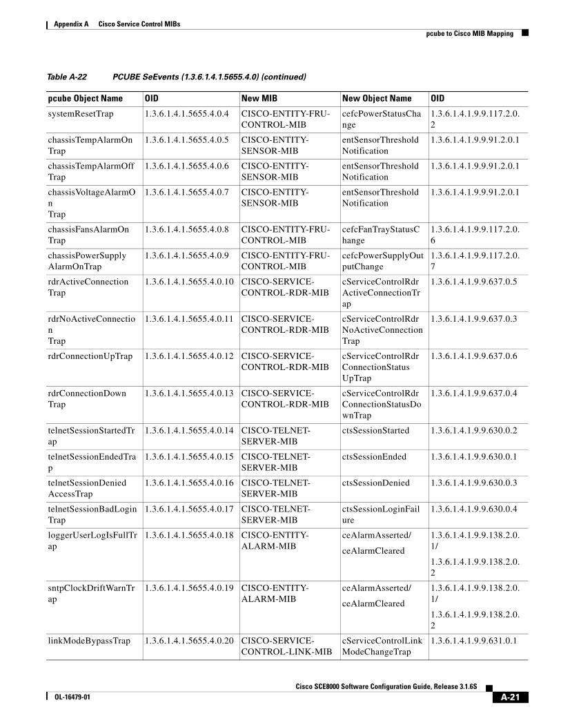
Appendix A Cisco Service Control MIBs pcube to Cisco MIB Mapping
systemResetTrap 1.3.6.1.4.1.5655.4.0.4 CISCO-ENTITY-FRU- CONTROL-MIB
cefcPowerStatusChange
1.3.6.1.4.1.9.9.117.2.0.2
chassisTempAlarmOn Trap
1.3.6.1.4.1.5655.4.0.5 CISCO-ENTITY- SENSOR-MIB
entSensorThresholdNotification
1.3.6.1.4.1.9.9.91.2.0.1
chassisTempAlarmOff Trap
1.3.6.1.4.1.5655.4.0.6 CISCO-ENTITY- SENSOR-MIB
entSensorThresholdNotification
1.3.6.1.4.1.9.9.91.2.0.1
chassisVoltageAlarmOn Trap
1.3.6.1.4.1.5655.4.0.7 CISCO-ENTITY- SENSOR-MIB
entSensorThresholdNotification
1.3.6.1.4.1.9.9.91.2.0.1
chassisFansAlarmOn Trap
1.3.6.1.4.1.5655.4.0.8 CISCO-ENTITY-FRU- CONTROL-MIB
cefcFanTrayStatusChange
1.3.6.1.4.1.9.9.117.2.0.6
chassisPowerSupply AlarmOnTrap
1.3.6.1.4.1.5655.4.0.9 CISCO-ENTITY-FRU- CONTROL-MIB
cefcPowerSupplyOutputChange
1.3.6.1.4.1.9.9.117.2.0.7
rdrActiveConnection Trap
1.3.6.1.4.1.5655.4.0.10 CISCO-SERVICE- CONTROL-RDR-MIB
cServiceControlRdrActiveConnectionTrap
1.3.6.1.4.1.9.9.637.0.5
rdrNoActiveConnection Trap
1.3.6.1.4.1.5655.4.0.11 CISCO-SERVICE- CONTROL-RDR-MIB
cServiceControlRdrNoActiveConnection Trap
1.3.6.1.4.1.9.9.637.0.3
rdrConnectionUpTrap 1.3.6.1.4.1.5655.4.0.12 CISCO-SERVICE- CONTROL-RDR-MIB
cServiceControlRdrConnectionStatus UpTrap
1.3.6.1.4.1.9.9.637.0.6
rdrConnectionDown Trap
1.3.6.1.4.1.5655.4.0.13 CISCO-SERVICE- CONTROL-RDR-MIB
cServiceControlRdrConnectionStatusDownTrap
1.3.6.1.4.1.9.9.637.0.4
telnetSessionStartedTrap
1.3.6.1.4.1.5655.4.0.14 CISCO-TELNET- SERVER-MIB
ctsSessionStarted 1.3.6.1.4.1.9.9.630.0.2
telnetSessionEndedTrap
1.3.6.1.4.1.5655.4.0.15 CISCO-TELNET- SERVER-MIB
ctsSessionEnded 1.3.6.1.4.1.9.9.630.0.1
telnetSessionDenied AccessTrap
1.3.6.1.4.1.5655.4.0.16 CISCO-TELNET- SERVER-MIB
ctsSessionDenied 1.3.6.1.4.1.9.9.630.0.3
telnetSessionBadLogin Trap
1.3.6.1.4.1.5655.4.0.17 CISCO-TELNET- SERVER-MIB
ctsSessionLoginFailure
1.3.6.1.4.1.9.9.630.0.4
loggerUserLogIsFullTrap
1.3.6.1.4.1.5655.4.0.18 CISCO-ENTITY- ALARM-MIB
ceAlarmAsserted/
ceAlarmCleared
1.3.6.1.4.1.9.9.138.2.0.1/
1.3.6.1.4.1.9.9.138.2.0.2
sntpClockDriftWarnTrap
1.3.6.1.4.1.5655.4.0.19 CISCO-ENTITY- ALARM-MIB
ceAlarmAsserted/
ceAlarmCleared
1.3.6.1.4.1.9.9.138.2.0.1/
1.3.6.1.4.1.9.9.138.2.0.2
linkModeBypassTrap 1.3.6.1.4.1.5655.4.0.20 CISCO-SERVICE- CONTROL-LINK-MIB
cServiceControlLinkModeChangeTrap
1.3.6.1.4.1.9.9.631.0.1
Table A-22 PCUBE SeEvents (1.3.6.1.4.1.5655.4.0) (continued)
pcube Object Name OID New MIB New Object Name OID
A-21Cisco SCE8000 Software Configuration Guide, Release 3.1.6S
OL-16479-01

Appendix A Cisco Service Control MIBs pcube to Cisco MIB Mapping
linkModeForwarding Trap
1.3.6.1.4.1.5655.4.0.21 CISCO-SERVICE- CONTROL-LINK-MIB
cServiceControlLinkModeChangeTrap
1.3.6.1.4.1.9.9.631.0.1
linkModeCutoffTrap 1.3.6.1.4.1.5655.4.0.22 CISCO-SERVICE- CONTROL-LINK-MIB
cServiceControlLinkModeChangeTrap
1.3.6.1.4.1.9.9.631.0.1
moduleAttackFilter ActivatedTrap
1.3.6.1.4.1.5655.4.0.25 CISCO- SERVICE-CONTROL-ATTACK-MIB
cscaFilterChange 1.3.6.1.4.1.9.9.5555.0.1
moduleAttackFilter DeactivatedTrap
1.3.6.1.4.1.5655.4.0.26 CISCO- SERVICE-CONTROL-ATTACK-MIB
cscaFilterChange 1.3.6.1.4.1.9.9.5555.0.1
moduleEmAgentGenericTrap
1.3.6.1.4.1.5655.4.0.27 Not mapped
linkModeSniffingTrap 1.3.6.1.4.1.5655.4.0.28 CISCO-SERVICE- CONTROL-LINK-MIB
cServiceControlLinkModeChangeTrap
1.3.6.1.4.1.9.9.631.0.1
moduleRedundancy ReadyTrap
1.3.6.1.4.1.5655.4.0.29 CISCO-ENTITY- REDUNDANCY-MIB
ceRedunProtectStatusChange
1.3.6.1.4.1.9.9.498.0.2
moduleRedundant ConfigurationMismatch Trap
1.3.6.1.4.1.5655.4.0.30 CISCO-ENTITY- REDUNDANCY-MIB
ceRedunProtectStatusChange
1.3.6.1.4.1.9.9.498.0.2
moduleLostRedundancyTrap
1.3.6.1.4.1.5655.4.0.31 CISCO-ENTITY- REDUNDANCY-MIB
ceRedunProtectStatusChange
1.3.6.1.4.1.9.9.498.0.2
moduleSmConnection DownTrap
1.3.6.1.4.1.5655.4.0.32 CISCO-ENTITY- ALARM-MIB
ceAlarmAsserted/
ceAlarmCleared
1.3.6.1.4.1.9.9.138.2.0.1/
1.3.6.1.4.1.9.9.138.2.0.2
moduleSmConnectionUpTrap
1.3.6.1.4.1.5655.4.0.33 CISCO-ENTITY- ALARM-MIB
ceAlarmAsserted/
ceAlarmCleared
1.3.6.1.4.1.9.9.138.2.0.1/
1.3.6.1.4.1.9.9.138.2.0.2
moduleOperStatus ChangeTrap
1.3.6.1.4.1.5655.4.0.34 CISCO-ENTITY-FRU- CONTROL-MIB
cefcModuleStatusChange
1.3.6.1.4.1.9.9.117.2.0.1
portOperStatusChange Trap
1.3.6.1.4.1.5655.4.0.35 CISCO-ENTITY-FRU- CONTROL-MIB
cefcModuleStatusChange
1.3.6.1.4.1.9.9.117.2.0.1
chassisLineFeedAlarm OnTrap
1.3.6.1.4.1.5655.4.0.36 CISCO-ENTITY-FRU- CONTROL-MIB
cefcPowerStatusChange
1.3.6.1.4.1.9.9.117.2.0.2
rdrFormatterCategory DiscardingReportsTrap
1.3.6.1.4.1.5655.4.0.37 CISCO-SERVICE- CONTROL-RDR-MIB
cServiceControlRdrCategoryDiscarding ReportsTrap
1.3.6.1.4.1.9.9.637.0.2
rdrFormatterCategory StoppedDiscarding ReportsTrap
1.3.6.1.4.1.5655.4.0.38 CISCO-SERVICE- CONTROL-RDR-MIB
cServiceControlRdrCategoryStopped DiscardingReportsTrap
1.3.6.1.4.1.9.9.637.0.1
Table A-22 PCUBE SeEvents (1.3.6.1.4.1.5655.4.0) (continued)
pcube Object Name OID New MIB New Object Name OID
A-22Cisco SCE8000 Software Configuration Guide, Release 3.1.6S
OL-16479-01

Appendix A Cisco Service Control MIBs pcube to Cisco MIB Mapping
Note ApplicationGrp (1.3.6.1.4.1.5655.4.1.13) is not mapped to a current MIB.
sessionStartedTrap 1.3.6.1.4.1.5655.4.0.39 CISCO-SECURE- SHELL-MIB
cssSessionStartedTrap
1.3.6.1.4.1.9.9.339.0.3
sessionEndedTrap 1.3.6.1.4.1.5655.4.0.40 CISCO-SECURE- SHELL-MIB
cssSessionEndedTrap
1.3.6.1.4.1.9.9.339.0.1
sessionDeniedAccess Trap
1.3.6.1.4.1.5655.4.0.41 CISCO-SECURE- SHELL-MIB
cssSessionDeniedTrap
1.3.6.1.4.1.9.9.339.0.2
sessionBadLoginTrap 1.3.6.1.4.1.5655.4.0.42 CISCO-SECURE- SHELL-MIB
cssSessionDeniedTrap
cssSessionDeniedReason
1.3.6.1.4.1.9.9.339.0.2
1.3.6.1.4.1.9.9.339.1.3.2.1.4
illegalSubscriber MappingTrap
1.3.6.1.4.1.5655.4.0.43 CISCO- SERVICE-CONTROL- SUBSCRIBER-MIB
cServiceControlSubscriberMappingTrap
1.3.6.1.4.1.9.9.628.0.1
loggerLineAttackLog FullTrap
1.3.6.1.4.1.5655.4.0.44 CISCO-ENTITY- ALARM-MIB
ceAlarmAsserted/
ceAlarmCleared
1.3.6.1.4.1.9.9.138.2.0.1/
1.3.6.1.4.1.9.9.138.2.0.2
vasServerOpertional StatusChangeTrap
1.3.6.1.4.1.5655.4.0.45 CISCO-SERVICE- CONTROL-VAS-MIB
cscVasOperStatusChange
1.3.6.1.4.1.9.9.9999.0.1
pullRequestNumber 1.3.6.1.4.1.5655.4.0.46 Not mapped
pullRequestRetryFailed Trap
1.3.6.1.4.1.5655.4.0.47 Not mapped For SM connection issues the following notification can be used:
ceAlarmAsserted
ceAlarmCleared
For SM connection issues the following OIDs can be used:
1.3.6.1.4.1.9.9.138.2.0.1
1.3.6.1.4.1.9.9.138.2.0.2
mplsVpnTotalHW MappingsThreshold ExceededTrap
1.3.6.1.4.1.5655.4.0.48 CISCO-ENTITY- ALARM-MIB
ceAlarmAsserted/
ceAlarmCleared
1.3.6.1.4.1.9.9.138.2.0.1/
1.3.6.1.4.1.9.9.138.2.0.2
Table A-22 PCUBE SeEvents (1.3.6.1.4.1.5655.4.0) (continued)
pcube Object Name OID New MIB New Object Name OID
A-23Cisco SCE8000 Software Configuration Guide, Release 3.1.6S
OL-16479-01

Appendix A Cisco Service Control MIBs pcube to Cisco MIB Mapping
A-24Cisco SCE8000 Software Configuration Guide, Release 3.1.6S
OL-16479-01

Cisco SCE8OL-16479-01
A
P P E N D I X B Monitoring SCE Platform UtilizationThis module explains how to monitor SCE platforms that are installed in real traffic.
• SCE Platform Utilization Indicators, page B-1
• Service Loss, page B-2
As with any network device, the SCE platform has its performance and capacity envelopes. As the network evolves, the utilization of the SCE platform can increase and these envelopes might be reached. It is, therefore, advisable to monitor SCE platform to be sure that utilization remains at a level that supports reliable and consistent service.
When the SCE platform reaches its performance envelopes, it activates certain mechanisms that insure that no traffic will be dropped while in this state. These mechanisms will prioritize packet handling over service related actions. As a result, symptoms of service loss might be experienced. Following are several examples:
• Broken reports during the congestion period (sometimes appears as saw-tooth pattern).
• Bandwidth enforcement levels are not met.
• No UDP traffic is being reported (this is because the SCE platform will automatically filter all UDP traffic in certain cases as a last resort).
Monitoring the SCE platform can be divided onto two main areas:
• Monitoring SCE platform utilization
• Monitoring service loss
SCE Platform Utilization IndicatorsThe SCE platform exposes several indicators to allow the network operators to easily monitor whether it is working within its performance and capacity specifications:
• CPU Utilization, page B-2
• Flows Capacity, page B-2
• Subscribers Capacity, page B-2
B-1000 Software Configuration Guide, Rel 3.1.6S

Appendix B Monitoring SCE Platform Utilization Service Loss
CPU Utilization • SNMP
cpmCPUTotal1minRev and cpmCPUTotal5minRev, available for each Traffic Processor.
Refer to the Cisco process MIB for more information.
• CLI commands
show snmp MIB cisco-process | include cpmCPUTotal1minRev
show snmp MIB cisco-process | include cpmCPUTotal5minRev
It is advisable to consider sizing of the solution when the CPU utilization exceeds 75% regularly at peak hours.
Flows Capacity • SNMP
cscTpFlowsCapacityUtilization available for each Traffic Processor.
Refer to the cisco-service-control-tp-stats MIB for more information.
• CLI command
show snmp MIB cisco-service-control-tp-stats | include cscTpFlowsCapacityUtilization
It is advisable to consider sizing of the solution when the flows capacity utilization exceeds 90% regularly at peak hours.
Subscribers Capacity • SNMP
cServiceControlSubscribersInfoEntry
Refer to the cisco-service-control-subscriber MIB for more information
• CLI command
show snmp MIB cisco-service-control-subscriber
The Cisco SCE8000 platform supports up to 250K subscribers. You should make sure that the number of Introduced Subscribers plus the number of Anonymous Subscribers stays below this figure.
It is advisable that when subscribers utilization exceeds 90%, special attention should be given and sizing should be reconsidered.
Service LossService Loss is an event which occurs when the SCE platform does not provide the processing it was expected to perform for any transaction in the network. This can occur due to either CPU or Flows shortage.
B-2Cisco SCE8000 Software Configuration Guide, Rel 3.1.6S
OL-16479-01

Appendix B Monitoring SCE Platform Utilization Service Loss
There are two different situations which can result with service loss in the SCE platform:
• Temporary – This might occur when some network pattern which is short in its nature occurred and caused the SCE platform to exhaust some of it resources temporarily. An example could be a DDoS attack that the SCE platform could not detect and filter.
This is usually measured in seconds.
• Permanent – In cases where the SCE platform is installed in locations where the network traffic does not match its capacity and performance envelopes, permanent service loss can occur.
This is measured in hours.
Service loss is defined as the ratio of the number of packets that did not receive service as expected to the total number of packets that were processed by the SCE platform.
Monitoring Service Loss • SNMP
cscTpServiceLoss MIB available for each traffic processor.
Refer to the cisco-service-control-tp-stats MIB for more information.
It is expected that the SCE platform user will define timeslots in which this variable is monitored (reset it between timeslots).
Note The units for this variable are 0.001% and the information is rounded down.
B-3Cisco SCE8000 Software Configuration Guide, Rel 3.1.6S
OL-16479-01

Appendix B Monitoring SCE Platform Utilization Service Loss
B-4Cisco SCE8000 Software Configuration Guide, Rel 3.1.6S
OL-16479-01
Recommended