Dynamic Multipoint IPsec VPNs (Using MultipointGRE/NHRP to Scale IPsec VPNs)
Document ID: 41940
Contents
Introduction Background Information The DMVPN Solution Automatic IPsec Encryption Initiation Dynamic Tunnel Creation for �Spoke−to−Hub� Links Dynamic Tunnel Creation for �Spoke−to−Spoke� Traffic Supporting Dynamic Routing Protocols Cisco Express Forwarding Fast Switching for mGRE Using Dynamic Routing Over IPsec Protected VPNs Base Configuration Examples of the Routing Tables on the Hub and Spoke Routers Reducing the Hub Router Configuration Size Supporting Dynamic Addresses on Spokes Dynamic Multipoint Hub and Spoke Dynamic Multipoint IPsec VPN RIP EIGRP OSPF Initial Conditions Conditions After a Dynamic Link Is Created Between Spoke1 and Spoke2 Dynamic Multipoint IPsec VPN with Dual Hubs Dual Hub − Single DMVPN Layout Initial Conditions and Changes Dual Hub − Dual DMVPN Layout Initial Conditions and Changes Conclusion Related Information
Introduction
This document discusses Dynamic Multipoint IPsec VPNs (DMVPN) and why a company might want todesign or migrate their network to make use of this new IPsec VPN solution in Cisco IOS® Software.
Background Information
Companies may need to interconnect many sites to a main site, and perhaps also to each other, across theInternet while encrypting the traffic to protect it. For example, a set of retail stores that need to connect to thecompany headquarters for inventory and ordering may also need to connect to other stores within thecompany to check out product availabilty. In the past, the only way to make the connection was to use aLayer−2 network such as ISDN or Frame Relay to interconnect everything. Setting up and paying for thesehard−wired links for internal IP traffic can be time consuming and costly. If all of the sites (including themain site) already have relatively cheap Internet access, then this Internet access can also be used for internalIP communication between the stores and headquarters by using IPsec tunnels to ensure privacy and dataintegrity.
In order for companies to build large IPsec networks interconnecting their sites across the Internet, you needto be able to scale the IPsec network. IPsec encrypts traffic between two endpoints (peers), and the encryptionis done by the two endpoints using a shared "secret". Since this secret is shared only between these twoendpoints, encrypted networks are inherently a collection of point−to−point links. Because of this, IPsec isintrinsically a point−to−point tunnel network. The most feasible method to scale a large point−to−pointnetwork is to organize it into a hub−and−spoke or full (partial) mesh network. In most networks, the majorityof the IP traffic is between the spokes and the hub, and very little is between the spokes, so thehub−and−spoke design is often the best choice. This design also matches with older Frame Relay networkssince it was prohibitively expensive to pay for links between all sites in these networks.
When using the Internet as the interconnection between the hub and spokes, the spokes also have direct accessto each other with no additional cost, but it has been very difficult, if not impossible, to set up and/or managea full (partial) mesh network. Full or partial mesh networks are often desirable because there can be a costsavings if spoke−to−spoke traffic can go directly through rather then via the hub. Spoke−to−spoke traffictraversing the hub uses hub resources and can incur extra delays, especially when using IPsec encryption,since the hub will need to decrypt the incoming packets from the sending spokes and then re−encrypt thetraffic to send it to the receiving spoke. Another example where direct spoke−to−spoke traffic would be usefulis the case where two spokes are in the same city and the hub is across the country.
As IPsec hub−and−spoke networks were deployed and grew in size, it became more desirable to have themroute IP packets as dynamically as possible. In the older Frame Relay hub−and−spoke networks this wasaccomplished by running a dynamic routing protocol like OSPF or EIGRP over the Frame Relay links. Thiswas useful for dynamically advertising the reachability of spoke networks and also to support redundancy inthe IP routing network. If the network lost a hub router, a backup hub router could automatically take over toretain network connectivity to the spoke networks.
There is a fundamental problem with IPsec tunnels and dynamic routing protocols. Dynamic routing protocolsrely on using IP multicast or broadcast packets, but IPsec does not support encrypting multicast or broadcastpackets. The current method for solving this problem is to use generic routing encapsulation (GRE) tunnels incombination with IPsec encryption.
GRE tunnels do support transporting IP multicast and broadcast packets to the other end of the GRE tunnel.The GRE tunnel packet is an IP unicast packet, so the GRE packet can be encrypted using IPsec. In thisscenario, GRE does the tunneling work and IPsec does the encryption part of supporting the VPN network.When GRE tunnels are configured, the IP addresses for the endpoints of the tunnel (tunnel source ..., tunneldestination ...) must be known by the other endpoint and must be routable over the Internet. This means thatthe hub and all of the spoke routers in this network must have static non−private IP addresses.
For small site connections to the Internet, it is typical for a spoke's external IP address to change each time itconnects to the Internet because their Internet Service Provider (ISP) dynamically provides the outsideinterface address (via Dynamic Host Configuration Protocol (DHCP)) each time the spoke comes on line(asymmetric digital subscriber line (ADSL) and Cable services). This dynamic allocation of the "outsideaddress" of the router allows the ISP to oversubscribe the use of their Internet address space, since not allusers will be online at the same time. It can be considerably more expensive to pay the provider to allocate astatic address for the spoke router. Running a dynamic routing protocol over an IPsec VPN requires the use ofGRE tunnels, but you lose the option of having spokes with dynamically allocated IP addresses on theiroutside physical interfaces.
The above restrictions and some others are summarized in the following four points:
IPsec uses an access control list (ACL) to define what data is to be encrypted. So, each time a new(sub)network is added behind a spoke or the hub, the customer must change the ACL on both the huband spoke routers. If the SP manages the router, then the customer must notify the SP in order to getthe IPsec ACL changed so that new traffic will be encrypted.
•

With large hub−and−spoke networks, the size of the configuration on the Hub router can become verylarge, to the extent that it is unusable. For example a hub router would need up to 3900 lines ofconfiguration to support 300 spoke routers. This is large enough that it would be difficult to show theconfiguration and to find the section of the configuration that is relevant to a current problem that isbeing debugged. Also this size configuration may be too large to fit in NVRAM and would need to bestored on Flash memory.
•
GRE + IPsec must know the endpoint peer address. The spokes' IP addresses are connected directly tothe Internet via their own ISP, and they are often set up so that their external interface addresses arenot fixed. The IP addresses can change each time the site comes online (via DHCP).
•
If the spokes need to directly talk with each other over the IPsec VPN, then the hub−and−spokenetwork must become a full mesh. Since it is not already known which spokes will need to talkdirectly with each other, a full mesh is required, even though each spoke may not need to talk directlywith every other spoke. Also, it is not feasible to configure IPsec on a small spoke router so that it hasdirect connectivity with all other spoke routers in the network; thus spoke routers may need to bemore powerful routers.
•
The DMVPN Solution
The DMVPN solution uses Multipoint GRE (mGRE) and Next Hop Resolution Protocol (NHRP), with IPsecand some new enhancements, to solve the above problems in a scalable manner.
Automatic IPsec Encryption Initiation
When not using the DMVPN solution, the IPsec encryption tunnel is not initiated until there is data traffic thatrequires the use of this IPsec tunnel. It may take 1 to 10 seconds to complete the initiation of the IPsec tunneland data traffic is dropped during this time. When using GRE with IPsec, the GRE tunnel configurationalready includes the GRE tunnel peer (tunnel destination &) address, which also is the IPsec peer address.Both of these addresses are preconfigured.
If you use Tunnel Endpoint Discovery (TED) and dynamic crypto maps on the hub router, then you can avoidhaving to preconfigure the IPsec peer addresses on the hub, but a TED probe and response needs to be sentand received before ISAKMP negotiation can start. This should not be necessary since, when using GRE, thepeer source and destination addresses are already known. They are either in the configuration or resolved withNHRP (for multipoint GRE tunnels).
With the DMVPN solution, IPsec is triggered immediately for both point−to−point and multipoint GREtunnels. Also, it is not necessary to configure any crypto ACLs, since these will be automatically derived fromthe GRE tunnel source and destination addresses. The following commands are used to define the IPsecencryption parameters. Notice that there is no set peer ... or match address ... commands required becausethis information is derived directly from the associated GRE tunnel or NHRP mappings.
crypto ipsec profile <profile−name> set transform−set <transform−name>
The following command associates a tunnel interface with the IPsec profile.
interface tunnel<number> ... tunnel protection ipsec profile <profile−name>
Dynamic Tunnel Creation for �Spoke−to−Hub� Links
No GRE or IPsec information about a spoke is configured on the hub router in the DMVPN network . Thespoke router's GRE tunnel is configured (via NHRP commands) with information about the hub router. When
the spoke router starts up, it automatically initiates the IPsec tunnel with the hub router as described above. Itthen uses NHRP to notify the hub router of its current physical interface IP address. This is useful for threereasons:
If the spoke router has its physical interface IP address assigned dynamically (such as with ADSL orCableModem), then the hub router cannot be configured with this information since each time thespoke router reloads it will get a new physical interface IP address.
•
Configuration of the hub router is shortened and simplified since it does not need to have any GRE orIPsec information about the peer routers. All of this information is learned dynamically via NHRP.
•
When you add a new spoke router to the DMVPN network, you do not need to change theconfiguration on the hub or on any of the current spoke routers. The new spoke router is configuredwith the hub information, and when it starts up, it dynamically registers with the hub router. Thedynamic routing protocol propagates the routing information for this spoke to the hub. The hubpropagates this new routing information to the other spokes. It also propagates the routing informationfrom the other spokes to this spoke.
•
Dynamic Tunnel Creation for �Spoke−to−Spoke� Traffic
As stated earlier, currently in a mesh network, all point−to−point IPsec (or IPsec+GRE) tunnels must beconfigured on all the routers, even if some/most of these tunnels are not running or needed at all times. Withthe DMVPN solution, one router is the hub, and all the other routers (spokes) are configured with tunnels tothe hub. The spoke−to−hub tunnels are up continuously, and spokes do not need configuration for directtunnels to any of the other spokes. Instead, when a spoke wants to transmit a packet to another spoke (such asthe subnet behind another spoke), it uses NHRP to dynamically determine the required destination address ofthe target spoke. The hub router acts as the NHRP server and handles this request for the source spoke. Thetwo spokes then dynamically create an IPsec tunnel between them (via the single mGRE interface) and datacan be directly transferred. This dynamic spoke−to−spoke tunnel will be automatically torn down after a(configurable) period of inactivity.
Supporting Dynamic Routing Protocols
The DMVPN solution is based on GRE tunnels which support tunneling multicast/broadcast IP packets, so theDMVPN solution also supports dynamic routing protocols running over the IPsec+mGRE tunnels. Previously,NHRP required you to explicitly configure the broadcast/multicast mapping for the tunnel destination IPaddresses to support GRE tunneling of Multicast and Broadcast IP packets. For example, at the hub youwould need the ip nhrp map multicast <spoke−n−addr> configuration line for each spoke. With theDMVPN solution, the spoke addresses are not known in advance, so this configuration is not possible.Instead, NHRP can be configured to automatically add each spoke to the multicast destination list on the hubwith the ip nhrp map multicast dynamic command. With this command, when the spoke routers registertheir unicast NHRP mapping with the NHRP server (hub), NHRP will also create a broadcast/multicastmapping for this spoke. This eliminates the need for the spoke addresses to be known in advance.
Cisco Express Forwarding Fast Switching for mGRE
Currently, traffic in an mGRE interface is process−switched, resulting in poor performance. The DMVPNsolution adds Cisco Express Forwarding switching for the mGRE traffic, resulting in much betterperformance. There are no configuration commands necessary to turn on this feature. If Cisco ExpressForwarding switching is allowed on the GRE tunnel interface and the outgoing/incoming physical interfaces,then the multipoint GRE tunnel packets will be Cisco Express Forwarding−switched.
Using Dynamic Routing Over IPsec Protected VPNs
This section describes the current (pre−DMVPN solution) state of affairs. IPsec is implemented on Ciscorouters via a set of commands that define the encryption and then a crypto map <map−name> commandapplied on the external interface of the router. Because of this design and the fact that there is not currently astandard for using IPsec to encrypt IP multicast/broadcast packets, IP routing protocol packets cannot be�forwarded� through the IPsec tunnel and any routing changes cannot be dynamically propagated to the otherside of the IPsec tunnel.
Note: All dynamic routing protocols except BGP use broadcast or multicast IP packets. GRE tunnels are usedin combination with IPsec to solve this problem.
GRE tunnels are implemented on Cisco routers by using a virtual tunnel interface (interface tunnel<#>). TheGRE tunneling protocol is designed to handle IP multicast/broadcast packets so a dynamic routing protocolcan be �run over" a GRE tunnel. GRE tunnel packets are IP unicast packets that encapsulate the original IPmulticast/unicast packet. You can then use IPsec to encrypt the GRE tunnel packet. You can also run IPsec intransport mode and save 20 bytes since GRE has already encapsulated the original data packet so you do notneed IPsec to encapsulate the GRE IP packet in another IP header.
When running IPsec in transport mode, there is a restriction that the IP source and destination addresses of thepacket to be encrypted must match the IPsec peer addresses (the router itself). In this case, this just means thatthe GRE tunnel endpoint and IPsec peer addresses must be the same. This is not a problem since the samerouters are both the IPsec and GRE tunnel endpoints. By combining GRE tunnels with IPsec encryption, youcan use a dynamic IP routing protocol to update the routing tables on both ends of the encrypted tunnel. TheIP routing table entries for the networks that were learned through the encrypted tunnel will have the other endof the tunnel (GRE tunnel interface IP address) as the IP next hop. Thus, if the networks change on either sideof the tunnel, then the other side will dynamically learn of the change and connectivity will continue withoutany configuration changes on the routers.
Base Configuration
The following is a standard point−to−point IPsec+GRE configuration. After this there is a series ofconfiguration examples where specific features of the DMVPN solution are added in steps to show thedifferent capabilities of DMVPN. Each example builds on the previous examples to show how to use theDMVPN solution in increasingly complex network designs. This succession of examples can be used as atemplate for migrating a current IPsec+GRE VPN to a DMVPN. You can stop "the migration" at any point ifthat particular configuration example matches your network design requirements.
IPsec + GRE Hub and Spoke (n = 1,2,3,...)

Hub Router
version 12.3 ! hostname Hub ! crypto isakmp policy 1 authentication pre−share crypto isakmp key cisco47 address 0.0.0.0 ! crypto ipsec transform−set trans2 esp−des esp−md5−hmac mode transport !
crypto map vpnmap1 local−address Ethernet0 crypto map vpnmap1 10 ipsec−isakmp set peer 172.16.1.1 set transform−set trans2 match address 101 crypto map vpnmap1 20 ipsec−isakmp set peer 172.16.2.1 set transform−set trans2 match address 102
. . . crypto map vpnmap1 <10*n> ipsec−isakmp set peer 172.16.<n>.1 set transform−set trans2 match address <n+100> !
interface Tunnel1 bandwidth 1000 ip address 10.0.0.1 255.255.255.252 ip mtu 1400 delay 1000 tunnel source Ethernet0 tunnel destination 172.16.1.1 ! interface Tunnel2 bandwidth 1000 ip address 10.0.0.5 255.255.255.252

ip mtu 1400 delay 1000 tunnel source Ethernet0 tunnel destination 172.16.2.1 ! . . . ! interface Tunnel<n> bandwidth 1000 ip address 10.0.0.<4n−3> 255.255.255.252 ip mtu 1400 delay 1000 tunnel source Ethernet0 tunnel destination 172.16.<n>.1 ! interface Ethernet0 ip address 172.17.0.1 255.255.255.0
crypto map vpnmap1 ! interface Ethernet1 ip address 192.168.0.1 255.255.255.0 !
router eigrp 1 network 10.0.0.0 0.0.0.255 network 192.168.0.0 0.0.0.255 no auto−summary ! access−list 101 permit gre host 172.17.0.1 host 172.16.1.1 access−list 102 permit gre host 172.17.0.1 host 172.16.2.1 ... access−list <n+100> permit gre host 172.17.0.1 host 172.16.<n>.1
Spoke1 Router
version 12.3 ! hostname Spoke1 !
crypto isakmp policy 1 authentication pre−share crypto isakmp key cisco47 address 0.0.0.0 ! crypto ipsec transform−set trans2 esp−des esp−md5−hmac mode transport ! crypto map vpnmap1 local−address Ethernet0 crypto map vpnmap1 10 ipsec−isakmp set peer 172.17.0.1 set transform−set trans2 match address 101 ! interface Tunnel0 bandwidth 1000 ip address 10.0.0.2 255.255.255.252 ip mtu 1400 delay 1000 tunnel source Ethernet0 tunnel destination 172.17.0.1 ! interface Ethernet0 ip address 172.16.1.1 255.255.255.252
crypto map vpnmap1 ! interface Ethernet1 ip address 192.168.1.1 255.255.255.0

!router eigrp 1
network 10.0.0.0 0.0.0.255 network 192.168.1.0 0.0.0.255 no auto−summary ! access−list 101 permit gre host 172.16.1.1 host 172.17.0.1
Spoke2 Router
version 12.3 ! hostname Spoke2 ! crypto isakmp policy 1 authentication pre−share crypto isakmp key cisco47 address 0.0.0.0 ! crypto ipsec transform−set trans2 esp−des esp−md5−hmac mode transport !
crypto map vpnmap1 local−address Ethernet0 crypto map vpnmap1 10 ipsec−isakmp set peer 172.17.0.1 set transform−set trans2 match address 101 ! interface Tunnel0 bandwidth 1000 ip address 10.0.0.6 255.255.255.252 ip mtu 1400 delay 1000 tunnel source Ethernet0 tunnel destination 172.17.0.1 ! interface Ethernet0 ip address 172.16.2.1 255.255.255.252
crypto map vpnmap1 ! interface Ethernet1 ip address 192.168.2.1 255.255.255.0 !
router eigrp 1 network 10.0.0.0 0.0.0.255 network 192.168.2.0 0.0.0.255 no auto−summary ! access−list 101 permit gre host 172.16.2.1 host 172.17.0.1
Spoke<n> Router
version 12.3 ! hostname Spoke<n> ! crypto isakmp policy 1 authentication pre−share crypto isakmp key cisco47 address 0.0.0.0 !
crypto ipsec transform−set trans2 esp−des esp−md5−hmac mode transport ! crypto map vpnmap1 local−address Ethernet0 crypto map vpnmap1 10 ipsec−isakmp

set peer 172.17.0.1 set transform−set trans2 match address 101 ! interface Tunnel0 bandwidth 1000 ip address 10.0.0.<4n−2> 255.255.255.252 ip mtu 1400 delay 1000 tunnel source Ethernet0 tunnel destination 172.17.0.1 ! interface Ethernet0 ip address 172.16.<n>.1 255.255.255.252
crypto map vpnmap1 ! interface Ethernet1 ip address 192.168.<n>.1 255.255.255.0 !
router eigrp 1 network 10.0.0.0 0.0.0.255 network 192.168.<n>.0 0.0.0.255 no auto−summary ! access−list 101 permit gre host 172.16.<n>.1 host 172.17.0.1
In the above configuration, ACLs are used to define what traffic will be encrypted. On both the hub and spokerouters, this ACL only needs to match the GRE tunnel IP packets. No matter how the networks change ateither end, the GRE IP tunnel packets will not change, so this ACL need not change.
Note: When using Cisco IOS software versions prior to 12.2(13)T, you must apply the crypto map vpnmap1configuration command to both the GRE tunnel interfaces (Tunnel<x>) and the physical interface (Ethernet0).With Cisco IOS version 12.2(13)T and later, you only apply the crypto map vpnmap1 configurationcommand to the physical interface (Ethernet0).
Examples of the Routing Tables on the Hub and Spoke Routers
Routing Table on Hub Router
172.17.0.0/24 is subnetted, 1 subnets C 172.17.0.0 is directly connected, Ethernet0 10.0.0.0/30 is subnetted, <n> subnets C 10.0.0.0 is directly connected, Tunnel1 C 10.0.0.4 is directly connected, Tunnel2 ... C 10.0.0.<4n−4> is directly connected, Tunnel<n> C 192.168.0.0/24 is directly connected, Ethernet1 D 192.168.1.0/24 [90/2841600] via 10.0.0.2, 18:28:19, Tunnel1 D 192.168.2.0/24 [90/2841600] via 10.0.0.6, 2d05h, Tunnel2 ... D 192.168.<n>.0/24 [90/2841600] via 10.0.0.<4n−2>, 2d05h, Tunnel<n>
Routing Table on Spoke1 Router
172.16.0.0/24 is subnetted, 1 subnets C 172.16.1.0 is directly connected, Ethernet0 10.0.0.0/30 is subnetted, <n> subnets C 10.0.0.0 is directly connected, Tunnel1 D 10.0.0.4 [90/2841600] via 10.0.0.1, 23:00:58, Tunnel0 ... D 10.0.0.<4n−4> [90/2841600] via 10.0.0.1, 23:00:58, Tunnel0 D 192.168.0.0/24 [90/2841600] via 10.0.0.1, 23:00:58, Tunnel0

C 192.168.1.0/24 is directly connected, Loopback0 D 192.168.2.0/24 [90/3097600] via 10.0.0.1, 23:00:58, Tunnel0 ... D 192.168.<n>.0/24 [90/3097600] via 10.0.0.1, 23:00:58, Tunnel0
Routing Table on Spoke<n> Router
172.16.0.0/24 is subnetted, 1 subnets C 172.16.<n>.0 is directly connected, Ethernet0 10.0.0.0/30 is subnetted, <n> subnets D 10.0.0.0 [90/2841600] via 10.0.0.1, 22:01:21, Tunnel0 D 10.0.0.4 [90/2841600] via 10.0.0.1, 22:01:21, Tunnel0 ... C 10.0.0.<4n−4> is directly connected, Tunnel0 D 192.168.0.0/24 [90/2841600] via 10.0.0.1, 22:01:21, Tunnel0 D 192.168.1.0/24 [90/3097600] via 10.0.0.1, 22:01:21, Tunnel0 D 192.168.2.0/24 [90/3097600] via 10.0.0.1, 22:01:21, Tunnel0 ... C 192.168.<n>.0/24 is directly connected, Ethernet0
This is a basic working configuration, and is used as a starting point for comparison with the more complexconfigurations possible using the DMVPN solution. The first change will reduce the size of the configurationon the hub router. This is not important with small numbers of spoke routers, but it does become critical whenthere are more than 50 to 100 spoke routers.
Reducing the Hub Router Configuration Size
In the following example, the configuration is minimally changed on the hub router from multiple GREpoint−to−point tunnel interfaces to a single GRE multipoint tunnel interface. This is a first step into theDMVPN solution.
There is a unique block of configuration lines on the hub router to define the crypto map characteristics foreach spoke router. This piece of the configuration defines the crypto ACL and the GRE tunnel interface forthat spoke router. These characteristics are mostly the same for all the spokes, except for IP addresses (setpeer &, tunnel destination &).
Looking at the above configuration on the hub router, you see that there are at least 13 lines of configurationper spoke router; four for the crypto map, one for the crypto ACL, and eight for the GRE tunnel interface. Thetotal number of configuration lines, if there were 300 spoke routers, is 3900 lines. You also need 300 (/30)subnets for addressing each tunnel link. A configuration of this size is very hard to manage and even moredifficult when troubleshooting the VPN network. To reduce this value, you could use dynamic crypto maps,which would reduce the above value by 1200 lines, leaving 2700 lines in a 300−spoke network.
Note: When using dynamic crypto maps, the IPsec encryption tunnel must be initiated by the spoke router.You can also use ip unnumbered <interface> to reduce the number of subnets needed for the GRE tunnels,but this may make troubleshooting more difficult later.
With the DMVPN solution, you can configure a single multipoint GRE tunnel interface and a single IPsecprofile on the hub router to handle all spoke routers. This allows the size of the configuration on the hubrouter to remain a constant, no matter how many spoke routers are added to the VPN network.
The DMVPN solution introduces the following new commands:
crypto ipsec profile <name> <ipsec parameters>
tunnel protection ipsec profile <name>
ip nhrp map multicast dynamic
The crypto ipsec profile <name> command is used like a dynamic crypto map, and it is designed specificallyfor tunnel interfaces. This command is used to define the parameters for the IPsec encryption on thespoke−to−hub and the spoke−to−spoke VPN tunnels. The only parameter that is required under the profile isthe transform set. The IPsec peer address and the match address ... clause for the IPsec proxy areautomatically derived from the NHRP mappings for the GRE tunnel.
The tunnel protection ipsec profile <name> command is configured under the GRE tunnel interface and isused to associate the GRE tunnel interface with the IPsec profile. In addition, the tunnel protection ipsecprofile <name> command can also be used with a point−to−point GRE tunnel. In this case it will derive theIPsec peer and proxy information from the tunnel source ... and tunnel destination ... configuration. Thissimplifies the configuration since the IPsec peer and the crypto ACLs are no longer needed.
Note: The tunnel protection & command specifies that the IPsec encryption will be done after the GREencapsulation has been added to the packet.
These first two new commands are similar to configuring a crypto map and assigning the crypto map to aninterface using the crypto map <name> command. The big difference is that, with the new commands, youdo not need to specify the IPsec peer address or an ACL to match the packets to be encrypted. Theseparameters are automatically determined from the NHRP mappings for the mGRE tunnel interface.
Note: When using the tunnel protection & command on the tunnel interface, a crypto map ... command isnot configured on the physical outgoing interface.
The last new command, ip nhrp map multicast dynamic, allows NHRP to automatically add spoke routersto the multicast NHRP mappings when these spoke routers initiate the mGRE+IPsec tunnel and register theirunicast NHRP mappings. This is needed to enable dynamic routing protocols to work over the mGRE+IPsectunnels between the hub and spokes. If this command was not available, then the hub router would need tohave a separate configuration line for a multicast mapping to each spoke.
Note: With this configuration, the spoke routers must initiate the mGRE+IPsec tunnel connection, since thehub router is not configured with any information about the spokes. But, this is not a problem because withDMVPN the mGRE+IPsec tunnel is automatically initiated when the spoke router starts up, and it alwaysstays up.
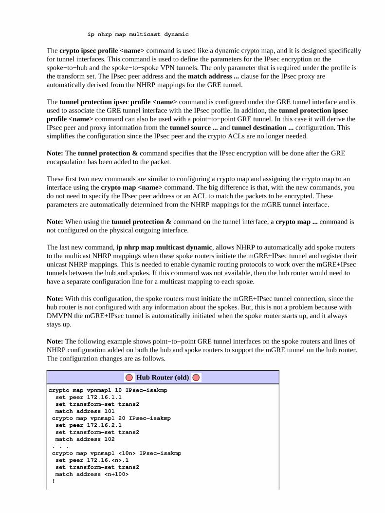
Note: The following example shows point−to−point GRE tunnel interfaces on the spoke routers and lines ofNHRP configuration added on both the hub and spoke routers to support the mGRE tunnel on the hub router.The configuration changes are as follows.
Hub Router (old)
crypto map vpnmap1 10 IPsec−isakmp set peer 172.16.1.1 set transform−set trans2 match address 101 crypto map vpnmap1 20 IPsec−isakmp set peer 172.16.2.1 set transform−set trans2 match address 102 . . . crypto map vpnmap1 <10n> IPsec−isakmp set peer 172.16.<n>.1 set transform−set trans2 match address <n+100> !

interface Tunnel1 bandwidth 1000 ip address 10.0.0.1 255.255.255.252 ip mtu 1400 delay 1000 tunnel source Ethernet0 tunnel destination 172.16.1.1 ! interface Tunnel2 bandwidth 1000 ip address 10.0.0.5 255.255.255.252 ip mtu 1400 delay 1000 tunnel source Ethernet0 tunnel destination 172.16.2.1 ! . . . ! interface Tunnel<n> bandwidth 1000 ip address 10.0.0.<4n−1> 255.255.255.252 ip mtu 1400 delay 1000 tunnel source Ethernet0 tunnel destination 172.16.<n>.1 ! interface Ethernet0 ip address 172.17.0.1 255.255.255.0
crypto map vpnmap1 !
access−list 101 permit gre host 172.17.0.1 host 172.16.1.1 access−list 102 permit gre host 172.17.0.1 host 172.16.2.1 . . . access−list <n+100> permit gre host 172.17.0.1 host 172.16.<n>.1
Hub Router (new)
crypto ipsec profile vpnprof set transform−set trans2 ! interface Tunnel0 bandwidth 1000
ip address 10.0.0.1 255.255.255.0 ip mtu 1400 ip nhrp authentication test ip nhrp map multicast dynamic ip nhrp network−id 100000 ip nhrp holdtime 600 no ip split−horizon eigrp 1 delay 1000 tunnel source Ethernet0
tunnel mode gre multipoint tunnel key 100000 tunnel protection ipsec profile vpnprof ! interface Ethernet0 ip address 172.17.0.1 255.255.255.0
Spoke<n> Router (old)
crypto map vpnmap1 10 IPsec−isakmp set peer 172.17.0.1 set transform−set trans2 match address 101

! interface Tunnel0 bandwidth 1000
ip address 10.0.0.<4n−2> 255.255.255.252 ip mtu 1400 delay 1000 tunnel source Ethernet0 tunnel destination 172.17.0.1 !interface Ethernet0 ip address 172.16.<n>.1 255.255.255.252
crypto map vpnmap1! . . . ! access−list 101 permit gre host 172.16.<n>.1 host 172.17.0.1 !
Spoke<n> Router (new)
crypto map vpnmap1 10 IPsec−isakmp set peer 172.17.0.1 set transform−set trans2 match address 101 ! interface Tunnel0 bandwidth 1000
ip address 10.0.0.<n+1> 255.255.255.0 ip mtu 1400 ip nhrp authentication test ip nhrp map 10.0.0.1 172.17.0.1 ip nhrp network−id 100000 ip nhrp holdtime 300 ip nhrp nhs 10.0.0.1 delay 1000 tunnel source Ethernet0 tunnel destination 172.17.0.1
tunnel key 100000 !interface Ethernet0 ip address 172.16.<n>.1 255.255.255.252
crypto map vpnmap1! . . . ! access−list 101 permit gre host 172.16.<n>.1 host 172.17.0.1 !
On the spoke routers, the subnet mask has changed, and NHRP commands have been added under the tunnelinterface. The NHRP commands are necessary since the hub router is now using NHRP to map the spoketunnel interface IP address to the spoke physical interface IP address.
ip address 10.0.0.<n+1> 255.255.255.0ip mtu 1400ip nhrp authentication testip nhrp map 10.0.0.1 172.17.0.1ip nhrp network−id 100000ip nhrp holdtime 300ip nhrp nhs 10.0.0.1
...tunnel key 100000
The subnet is now /24 instead of /30, so all of the nodes are in the same subnet, instead of different subnets.

The spokes still send spoke−to−spoke traffic via the hub since they are using a point−to−point GRE tunnelinterface. The ip nhrp authentication ..., ip nhrp network−id ... and tunnel key ... commands are used tomap the tunnel packets and the NHRP packets to the correct multipoint GRE tunnel interface and NHRPnetwork when they are received on the hub. The ip nhrp map ... and ip nhrp nhs ... commands are used byNHRP on the spoke to advertise the spokes NHRP mapping (10.0.0.<n+1> −−> 172.16.<n>.1) to the hub. The10.0.0.<n+1> address is retrieved from the ip address ... command on the tunnel interface and the172.16.<n>.1 address is retrieved from the tunnel destination ... command on the tunnel interface.
In a case where there are 300 spoke routers, this change would reduce the number of configuration lines onthe hub from 3900 lines to 16 lines (a reduction of 3884 lines). The configuration on each spoke router wouldincrease by 6 lines.
Supporting Dynamic Addresses on Spokes
On a Cisco router, each IPsec peer needs to be configured with the IP address of the other IPsec peer beforethe IPsec tunnel can be brought up. There is a problem with doing this if a spoke router has a dynamic addresson its physical interface, which is common for routers that are connected via DSL or Cable links.
TED allows one IPsec peer to find another IPsec peer by sending a special Internet Security Association andKey Management Protocol (ISAKMP) packet to the IP destination address of the original data packet thatneeded to be encrypted. The assumption is that this packet will traverse the intervening network along thesame path as taken by the IPsec tunnel packet. This packet will be picked up by the other−end IPsec peer,which will respond to the first peer. The two routers will then negotiate ISAKMP and IPsec SecurityAssociations (SAs) and bring up the IPsec tunnel. This will only work if the data packets to be encrypted haveroutable IP addresses.
TED can be used in combination with the GRE tunnels as configured in the previous section. This has beentested and works, though there was a bug in earlier versions of Cisco IOS software where TED forced all IPtraffic between the two IPsec peers to be encrypted, not just the GRE tunnel packets. The DMVPN solutionprovides this and additional capabilities without the hosts having to use Internet routable IP addresses andwithout having to send probe and response packets. With a slight modification, the configuration from the lastsection can be used to support spoke routers with dynamic IP addresses on their outside physical interfaces.
Hub Router (no change)
crypto ipsec profile vpnprof set transform−set trans2 ! interface Tunnel0 bandwidth 1000 ip address 10.0.0.1 255.255.255.0 ip mtu 1400 ip nhrp authentication test ip nhrp map multicast dynamic ip nhrp network−id 100000 ip nhrp holdtime 600 no ip split−horizon eigrp 1 delay 1000 tunnel source Ethernet0 tunnel mode gre multipoint tunnel key 100000 tunnel protection ipsec profile vpnprof ! interface Ethernet0 ip address 172.17.0.1 255.255.255.0
Spoke<n> Router (old)

crypto map vpnmap1 10 IPsec−isakmp set peer 172.17.0.1 set transform−set trans2 match address 101 ! ... !
access−list 101 permit gre host 172.16.<n>.1 host 172.17.0.1
Spoke<n> Router (new)
crypto map vpnmap1 10 IPsec−isakmp set peer 172.17.0.1 set transform−set trans2
set security−association level per−host match address 101 ! ... !
access−list 101 permit gre any host 172.17.0.1
The functionality that is used in the new spoke configuration is as follows.
When the GRE tunnel interface comes up, it will start sending NHRP registration packets to the hubrouter. These NHRP registration packets will trigger IPsec to be initiated. On the spoke router, the setpeer <peer−address> and match ip access−list <ACL> commands are configured. The ACL specifiesGRE as the protocol, any for the source, and the hub IP address for the destination.
Note: It is important to note that any is being used as the source in the ACL, and this must be the casesince the IP address of the spoke router is dynamic and, therefore, not known before the physicalinterface is active. An IP subnet can be used for the source in the ACL if the dynamic spoke interfaceaddress will be restricted to an address within that subnet.
•
The set security−association level per−host command is used so that the IP source in the spokesIPsec proxy will be just the spokes current physical interface address (/32), rather than the "any" fromthe ACL. If the "any" from the ACL were used as the source in the IPsec proxy, it would preclude anyother spoke router from also setting up an IPsec+GRE tunnel with this hub. This is because theresulting IPsec proxy on the hub would be equivalent to permit gre host 172.17.0.1 any. This wouldmean that all GRE tunnel packets destined to any spoke would be encrypted and sent to the first spokethat established a tunnel with the hub, since its IPsec proxy matches GRE packets for every spoke.
•
Once the IPsec tunnel is set up, an NHRP registration packet goes from the spoke router to theconfigured Next Hop Server (NHS). The NHS is the hub router of this hub−and−spoke network. TheNHRP registration packet provides the information for the hub router to create an NHRP mapping forthis spoke router. With this mapping, the hub router can then forward unicast IP data packets to thisspoke router over the mGRE+IPsec tunnel. Also, the hub adds the spoke router to its NHRP multicastmapping list. The hub will then start sending dynamic IP routing multicast packets to the spoke (if adynamic routing protocol is configured). The spoke will then become a routing protocol neighbor ofthe hub, and they will exchange routing updates.
•
IPsec + mGRE Hub and Spoke

Hub Router
version 12.3 ! hostname Hub ! crypto isakmp policy 1 authentication pre−share crypto isakmp key cisco47 address 0.0.0.0 ! crypto ipsec transform−set trans2 esp−des esp−md5−hmac mode transport ! crypto ipsec profile vpnprof set transform−set trans2 ! interface Tunnel0 bandwidth 1000
ip address 10.0.0.1 255.255.255.0 ip mtu 1400 ip nhrp authentication test ip nhrp map multicast dynamic ip nhrp network−id 100000 ip nhrp holdtime 600 no ip split−horizon eigrp 1 delay 1000 tunnel source Ethernet0 tunnel mode gre multipoint tunnel key 100000 tunnel protection ipsec profile vpnprof ! interface Ethernet0 ip address 172.17.0.1 255.255.255.0 ! interface Ethernet1 ip address 192.168.0.1 255.255.255.0 !

router eigrp 1 network 10.0.0.0 0.0.0.255 network 192.168.0.0 0.0.0.255 no auto−summary !
Notice in the above hub configuration that the IP addresses of the spoke routers are not configured. Thespoke�s external physical interface and the mapping to the spoke�s tunnel interface IP addresses are learneddynamically by the hub via NHRP. This allows the spoke�s external physical interface IP address to bedynamically assigned.
Spoke1 Router
version 12.3 ! hostname Spoke1 ! crypto isakmp policy 1 authentication pre−share crypto isakmp key cisco47 address 0.0.0.0 0.0.0.0 ! crypto ipsec transform−set trans2 esp−des esp−md5−hmac mode transport ! crypto map vpnmap1 local−address Ethernet0 crypto map vpnmap1 10 IPsec−isakmp set peer 172.17.0.1
set security−association level per−host set transform−set trans2 match address 101 ! interface Tunnel0 bandwidth 1000
ip address 10.0.0.2 255.255.255.0 ip mtu 1400 ip nhrp authentication test ip nhrp map 10.0.0.1 172.17.0.1 ip nhrp network−id 100000 ip nhrp holdtime 300 ip nhrp nhs 10.0.0.1 delay 1000 tunnel source Ethernet0 tunnel destination 172.17.0.1 tunnel key 100000 ! interface Ethernet0
ip address dhcp hostname Spoke1 crypto map vpnmap1 ! interface Ethernet1 ip address 192.168.1.1 255.255.255.0 ! router eigrp 1 network 10.0.0.0 0.0.0.255 network 192.168.1.0 0.0.0.255 no auto−summary !
access−list 101 permit gre 172.16.1.0 0.0.0.255 host 172.17.0.1
Spoke2 Router
version 12.3 !
hostname Spoke2 ! crypto isakmp policy 1 authentication pre−share crypto isakmp key cisco47 address 0.0.0.0 0.0.0.0 ! crypto ipsec transform−set trans2 esp−des esp−md5−hmac mode transport ! crypto map vpnmap1 local−address Ethernet0 crypto map vpnmap1 10 IPsec−isakmp set peer 172.17.0.1
set security−association level per−host set transform−set trans2 match address 101 ! interface Tunnel0 bandwidth 1000
ip address 10.0.0.3 255.255.255.0 ip mtu 1400 ip nhrp authentication test ip nhrp map 10.0.0.1 172.17.0.1 ip nhrp network−id 100000 ip nhrp holdtime 300 ip nhrp nhs 10.0.0.1 delay 1000 tunnel source Ethernet0 tunnel destination 172.17.0.1 tunnel key 100000 ! interface Ethernet0
ip address dhcp hostname Spoke2 crypto map vpnmap1 ! interface Ethernet1 ip address 192.168.2.1 255.255.255.0 ! router eigrp 1 network 10.0.0.0 0.0.0.255 network 192.168.1.0 0.0.0.255 no auto−summary !
access−list 101 permit gre 172.16.2.0 0.0.0.255 host 172.17.0.1
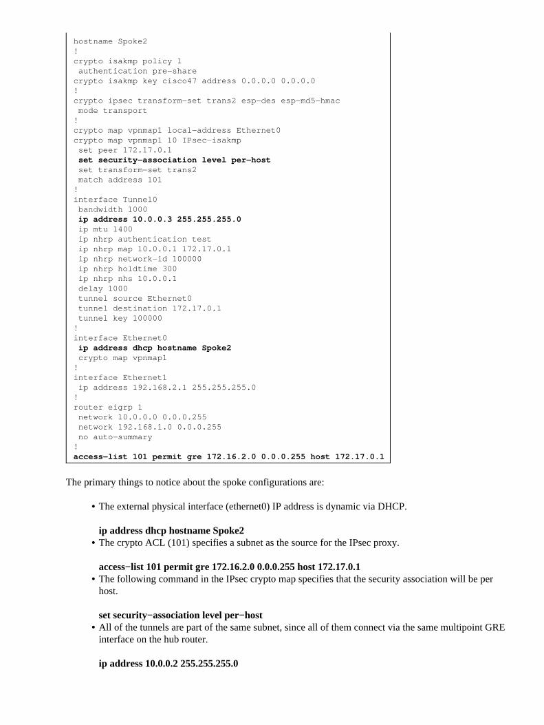
The primary things to notice about the spoke configurations are:
The external physical interface (ethernet0) IP address is dynamic via DHCP.
ip address dhcp hostname Spoke2
•
The crypto ACL (101) specifies a subnet as the source for the IPsec proxy.
access−list 101 permit gre 172.16.2.0 0.0.0.255 host 172.17.0.1
•
The following command in the IPsec crypto map specifies that the security association will be perhost.
set security−association level per−host
•
All of the tunnels are part of the same subnet, since all of them connect via the same multipoint GREinterface on the hub router.
ip address 10.0.0.2 255.255.255.0
•
The combination of these three commands make it unnecessary for the spoke�s external physical interface IPaddress to be configured. The IPsec proxy that is used will be host−based rather then subnet−based.
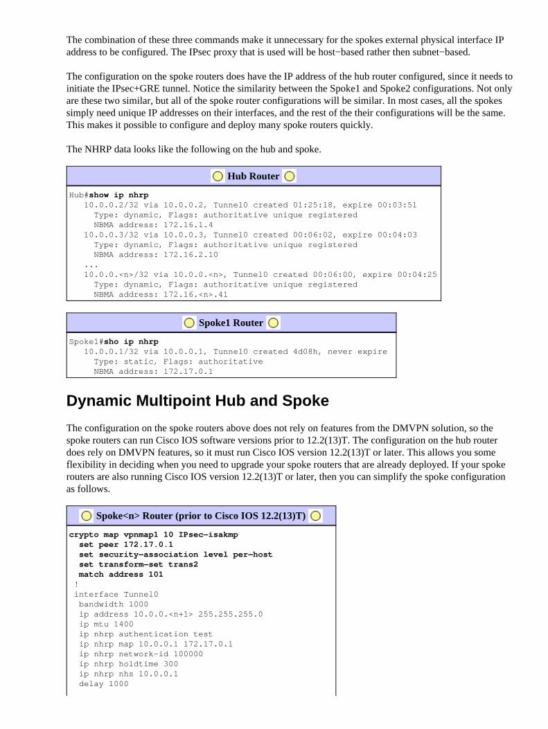
The configuration on the spoke routers does have the IP address of the hub router configured, since it needs toinitiate the IPsec+GRE tunnel. Notice the similarity between the Spoke1 and Spoke2 configurations. Not onlyare these two similar, but all of the spoke router configurations will be similar. In most cases, all the spokessimply need unique IP addresses on their interfaces, and the rest of the their configurations will be the same.This makes it possible to configure and deploy many spoke routers quickly.
The NHRP data looks like the following on the hub and spoke.
Hub Router
Hub#show ip nhrp 10.0.0.2/32 via 10.0.0.2, Tunnel0 created 01:25:18, expire 00:03:51 Type: dynamic, Flags: authoritative unique registered NBMA address: 172.16.1.4 10.0.0.3/32 via 10.0.0.3, Tunnel0 created 00:06:02, expire 00:04:03 Type: dynamic, Flags: authoritative unique registered NBMA address: 172.16.2.10 ... 10.0.0.<n>/32 via 10.0.0.<n>, Tunnel0 created 00:06:00, expire 00:04:25 Type: dynamic, Flags: authoritative unique registered NBMA address: 172.16.<n>.41
Spoke1 Router
Spoke1#sho ip nhrp 10.0.0.1/32 via 10.0.0.1, Tunnel0 created 4d08h, never expire Type: static, Flags: authoritative NBMA address: 172.17.0.1
Dynamic Multipoint Hub and Spoke
The configuration on the spoke routers above does not rely on features from the DMVPN solution, so thespoke routers can run Cisco IOS software versions prior to 12.2(13)T. The configuration on the hub routerdoes rely on DMVPN features, so it must run Cisco IOS version 12.2(13)T or later. This allows you someflexibility in deciding when you need to upgrade your spoke routers that are already deployed. If your spokerouters are also running Cisco IOS version 12.2(13)T or later, then you can simplify the spoke configurationas follows.
Spoke<n> Router (prior to Cisco IOS 12.2(13)T)
crypto map vpnmap1 10 IPsec−isakmp set peer 172.17.0.1 set security−association level per−host set transform−set trans2 match address 101 ! interface Tunnel0 bandwidth 1000 ip address 10.0.0.<n+1> 255.255.255.0 ip mtu 1400 ip nhrp authentication test ip nhrp map 10.0.0.1 172.17.0.1 ip nhrp network−id 100000 ip nhrp holdtime 300 ip nhrp nhs 10.0.0.1 delay 1000

tunnel source Ethernet0 tunnel destination 172.17.0.1 tunnel key 100000 ! interface Ethernet0 ip address dhcp hostname Spoke<n>
crypto map vpnmap1 ! . . . !
access−list 101 permit gre any host 172.17.0.1
Spoke<n> Router (after Cisco IOS 12.2(13)T)
crypto ipsec profile vpnprof set transform−set trans2 ! interface Tunnel0 bandwidth 1000 ip address 10.0.0.<n+1> 255.255.255.0 ip mtu 1400 ip nhrp authentication test ip nhrp map 10.0.0.1 172.17.0.1 ip nhrp network−id 100000 ip nhrp holdtime 300 ip nhrp nhs 10.0.0.1 delay 1000 tunnel source Ethernet0 tunnel destination 172.17.0.1 tunnel key 100000
tunnel protection ipsec profile vpnprof ! interface Ethernet0 ip address dhcp hostname Spoke<n> !
Notice that we have done the following:
Removed the crypto map vpnmap1 10 ipsec−isakmp command and replaced it with crypto ipsecprofile vpnprof.
1.
Removed the crypto map vpnmap1 command from the Ethernet0 interfaces and put the tunnelprotection ipsec profile vpnprof command on the Tunnel0 interface.
2.
Removed the crypto ACL, access−list 101 permit gre any host 172.17.0.1.3.
In this case the IPsec peer addresses and proxies are automatically derived from the tunnel source ... andtunnel destination ... configuration. The peers and proxies are as follows (as seen in the output from showcrypto ipsec sa command):
...local ident (addr/mask/prot/port): (172.16.1.24/255.255.255.255/47/0)remote ident (addr/mask/prot/port): (172.17.0.1/255.255.255.255/47/0)...local crypto endpt.: 172.17.1.24, remote crypto endpt.:172.17.0.1...
In summary, the following full configurations include all of the changes made up to this point from the BaseConfiguration (IPsec+GRE hub and spoke).
Hub Router
version 12.3

! hostname Hub ! crypto isakmp policy 1 authentication pre−share crypto isakmp key cisco47 address 0.0.0.0 ! crypto ipsec transform−set trans2 esp−des esp−md5−hmac mode transport ! crypto ipsec profile vpnprof set transform−set trans2 ! interface Tunnel0 bandwidth 1000 ip address 10.0.0.1 255.255.255.0 ip mtu 1400 ip nhrp authentication test ip nhrp map multicast dynamic ip nhrp network−id 100000 ip nhrp holdtime 600 no ip split−horizon eigrp 1 delay 1000 tunnel source Ethernet0 tunnel mode gre multipoint tunnel key 100000 tunnel protection ipsec profile vpnprof ! interface Ethernet0 ip address 172.17.0.1 255.255.255.0 ! interface Ethernet1 ip address 192.168.0.1 255.255.255.0 ! router eigrp 1 network 10.0.0.0 0.0.0.255 network 192.168.0.0 0.0.0.255 no auto−summary !
There are no changes in the hub configuration.
Spoke1 Router
version 12.3 ! hostname Spoke1 ! crypto isakmp policy 1 authentication pre−share crypto isakmp key cisco47 address 0.0.0.0 0.0.0.0 ! crypto ipsec transform−set trans2 esp−des esp−md5−hmac mode transport !
crypto ipsec profile vpnprof set transform−set trans2 ! interface Tunnel0 bandwidth 1000 ip address 10.0.0.2 255.255.255.0 ip mtu 1400 ip nhrp authentication test ip nhrp map 10.0.0.1 172.17.0.1 ip nhrp network−id 100000

ip nhrp holdtime 300 ip nhrp nhs 10.0.0.1 delay 1000 tunnel source Ethernet0 tunnel destination 172.17.0.1 tunnel key 100000
tunnel protection ipsec profile vpnprof ! interface Ethernet0 ip address dhcp hostname Spoke2 ! interface Ethernet1 ip address 192.168.1.1 255.255.255.0 ! router eigrp 1 network 10.0.0.0 0.0.0.255 network 192.168.1.0 0.0.0.255 no auto−summary !
Spoke2 Router
version 12.3 ! hostname Spoke2 ! crypto isakmp policy 1 authentication pre−share crypto isakmp key cisco47 address 0.0.0.0 0.0.0.0 ! crypto ipsec transform−set trans2 esp−des esp−md5−hmac mode transport !
crypto ipsec profile vpnprof set transform−set trans2 ! interface Tunnel0 bandwidth 1000 ip address 10.0.0.3 255.255.255.0 ip mtu 1400 ip nhrp authentication test ip nhrp map 10.0.0.1 172.17.0.1 ip nhrp network−id 100000 ip nhrp holdtime 300 ip nhrp nhs 10.0.0.1 delay 1000 tunnel source Ethernet0 tunnel destination 172.17.0.1 tunnel key 100000
tunnel protection ipsec profile vpnprof ! interface Ethernet0 ip address dhcp hostname Spoke2 ! interface Ethernet1 ip address 192.168.2.1 255.255.255.0 ! router eigrp 1 network 10.0.0.0 0.0.0.255 network 192.168.2.0 0.0.0.255 no auto−summary !

Dynamic Multipoint IPsec VPN
The concepts and configuration in this section show the full capabilities of DMVPN. NHRP provides thecapability for the spoke routers to dynamically learn the exterior physical interface address of the other spokerouters in the VPN network. This means that a spoke router will have enough information to dynamicallybuild an IPsec+mGRE tunnel directly to other spoke routers. This is advantageous since, if thisspoke−to−spoke data traffic was sent via the hub router, then it must be encrypted/decrypted, twice increasingthe delay and the load on the hub router. In order to use this feature, the spoke routers need to be switchedfrom point−to−point GRE (p−pGRE) to multipoint GRE (mGRE) tunnel interfaces. They also need to learnthe (sub)networks that are available behind the other spokes with an IP next−hop of the tunnel IP address ofthe other spoke router. The spoke routers learn these (sub)networks via the dynamic IP routing protocolrunning over the IPsec+mGRE tunnel with the hub.
The dynamic IP routing protocol running on the hub router can be configured to reflect the routes learnedfrom one spoke back out the same interface to all of the other spokes, but the IP next−hop on these routes willusually be the hub router, not the spoke router from which the hub learned this route.
Note: The dynamic routing protocol only runs on the hub and spoke links, it does not run on the dynamicspoke−to−spoke links.
The dynamic routing protocols (RIP, OSPF and EIGRP) need to be configured on the hub router to advertisethe routes back out the mGRE tunnel interface and to set the IP next−hop to the originating spoke router forroutes learned from one spoke when the route is advertised back out to the other spokes.
The following are requirements for the routing protocol configurations.
RIP
You need to turn off split horizon on the mGRE tunnel interface on the hub, otherwise RIP will not advertiseroutes learned via the mGRE interface back out that same interface.
no ip split−horizon
No other changes are necessary. RIP will automatically use the original IP next−hop on routes that itadvertises back out the same interface where it learned these routes.
EIGRP
You need to turn off split horizon on the mGRE tunnel interface on the hub, otherwise EIGRP will notadvertise routes learned via the mGRE interface back out that same interface.
no ip split−horizon eigrp <as>
EIGRP will, by default, set the IP next−hop to be the hub router for routes that it is advertising, even whenadvertising those routes back out the same interface where it learned them. So in this case, you need thefollowing configuration command to instruct EIGRP to use the original IP next−hop when advertising theseroutes.
no ip next−hop−self eigrp <as>
Note: The no ip next−hop−self eigrp <as> command will be available starting in Cisco IOS release 12.3(2).For Cisco IOS releases between 12.2(13)T and 12.3(2) you must do the following:
If spoke−to−spoke dynamic tunnels are not wanted, then the above command is not needed.• If spoke−to−spoke dynamic tunnels are wanted, then you must use process switching on the tunnelinterface on the spoke routers.
•
Otherwise, you will need to use a different routing protocol over the DMVPN.•
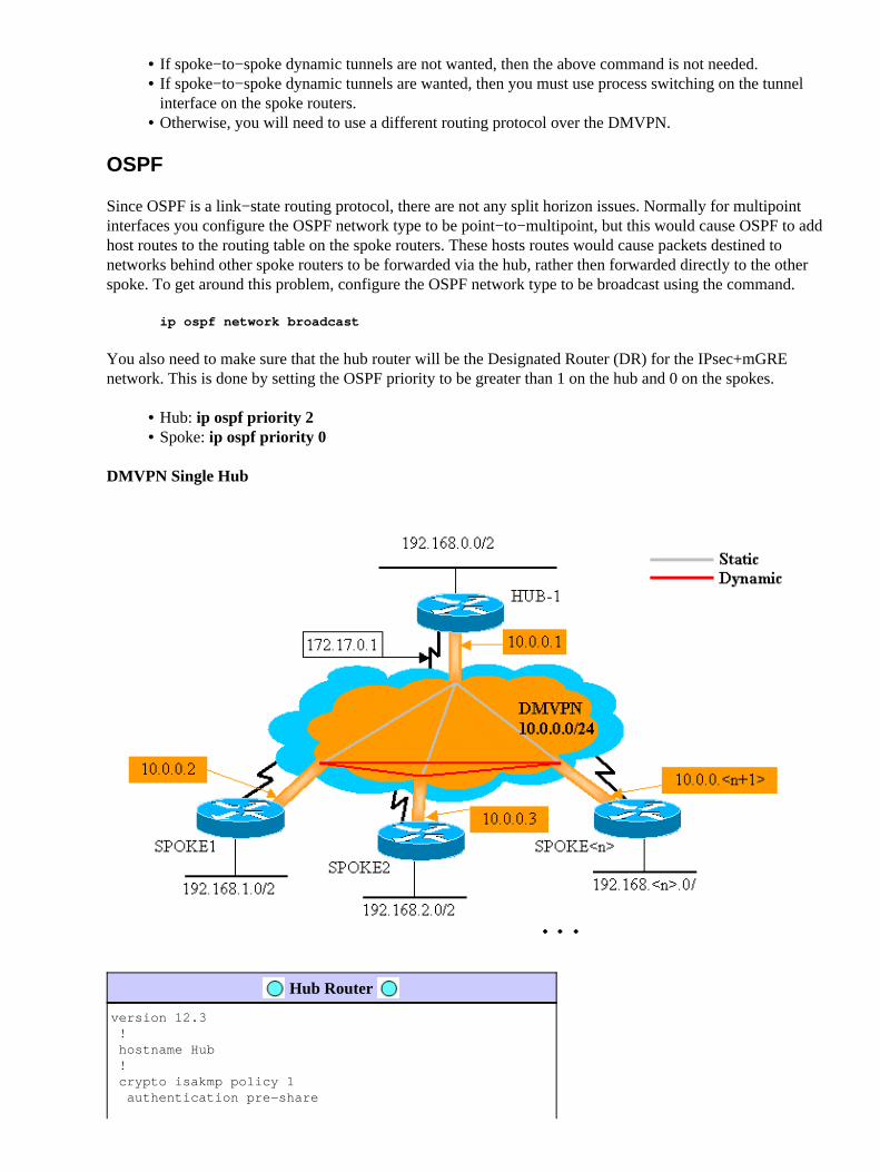
OSPF
Since OSPF is a link−state routing protocol, there are not any split horizon issues. Normally for multipointinterfaces you configure the OSPF network type to be point−to−multipoint, but this would cause OSPF to addhost routes to the routing table on the spoke routers. These hosts routes would cause packets destined tonetworks behind other spoke routers to be forwarded via the hub, rather then forwarded directly to the otherspoke. To get around this problem, configure the OSPF network type to be broadcast using the command.
ip ospf network broadcast
You also need to make sure that the hub router will be the Designated Router (DR) for the IPsec+mGREnetwork. This is done by setting the OSPF priority to be greater than 1 on the hub and 0 on the spokes.
Hub: ip ospf priority 2• Spoke: ip ospf priority 0•
DMVPN Single Hub
Hub Router
version 12.3 ! hostname Hub ! crypto isakmp policy 1 authentication pre−share

crypto isakmp key cisco47 address 0.0.0.0 ! crypto ipsec transform−set trans2 esp−des esp−md5−hmac mode transport ! crypto ipsec profile vpnprof set transform−set trans2 ! interface Tunnel0 bandwidth 1000 ip address 10.0.0.1 255.255.255.0 ip mtu 1400 ip nhrp authentication test ip nhrp map multicast dynamic ip nhrp network−id 100000 ip nhrp holdtime 600
ip ospf network broadcast ip ospf priority 2 delay 1000 tunnel source Ethernet0 tunnel mode gre multipoint tunnel key 100000 tunnel protection ipsec profile vpnprof ! interface Ethernet0 ip address 172.17.0.1 255.255.255.0 ! interface Ethernet1 ip address 192.168.0.1 255.255.255.0 !
router ospf 1 network 10.0.0.0 0.0.0.255 area 0 network 192.168.0.0 0.0.0.255 area 0 !
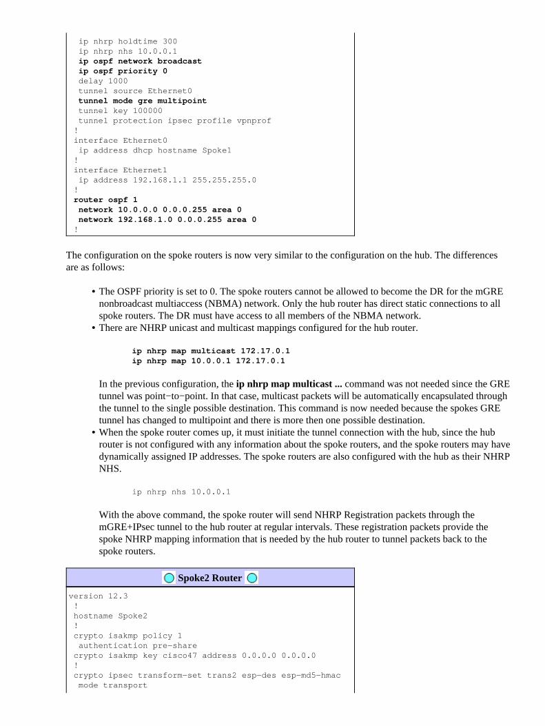
The only change in the hub configuration is that OSPF is the routing protocol instead of EIGRP. Notice thatthe OSPF network type is set to broadcast and the priority is set to 2. Setting the OSPF network type tobroadcast will cause OSPF to install routes for networks behind the spokes routers with an IP next−hopaddress as the GRE tunnel address for that spoke router.
Spoke1 Router
version 12.3 ! hostname Spoke1 ! crypto isakmp policy 1 authentication pre−share crypto isakmp key cisco47 address 0.0.0.0 0.0.0.0 ! crypto ipsec transform−set trans2 esp−des esp−md5−hmac mode transport ! crypto ipsec profile vpnprof set transform−set trans2 ! interface Tunnel0 bandwidth 1000 ip address 10.0.0.2 255.255.255.0 ip mtu 1400 ip nhrp authentication test
ip nhrp map multicast 172.17.0.1 ip nhrp map 10.0.0.1 172.17.0.1 ip nhrp network−id 100000
ip nhrp holdtime 300 ip nhrp nhs 10.0.0.1
ip ospf network broadcast ip ospf priority 0 delay 1000 tunnel source Ethernet0
tunnel mode gre multipoint tunnel key 100000 tunnel protection ipsec profile vpnprof ! interface Ethernet0 ip address dhcp hostname Spoke1 ! interface Ethernet1 ip address 192.168.1.1 255.255.255.0 !
router ospf 1 network 10.0.0.0 0.0.0.255 area 0 network 192.168.1.0 0.0.0.255 area 0 !
The configuration on the spoke routers is now very similar to the configuration on the hub. The differencesare as follows:
The OSPF priority is set to 0. The spoke routers cannot be allowed to become the DR for the mGREnonbroadcast multiaccess (NBMA) network. Only the hub router has direct static connections to allspoke routers. The DR must have access to all members of the NBMA network.
•
There are NHRP unicast and multicast mappings configured for the hub router.
ip nhrp map multicast 172.17.0.1ip nhrp map 10.0.0.1 172.17.0.1
In the previous configuration, the ip nhrp map multicast ... command was not needed since the GREtunnel was point−to−point. In that case, multicast packets will be automatically encapsulated throughthe tunnel to the single possible destination. This command is now needed because the spokes GREtunnel has changed to multipoint and there is more then one possible destination.
•
When the spoke router comes up, it must initiate the tunnel connection with the hub, since the hubrouter is not configured with any information about the spoke routers, and the spoke routers may havedynamically assigned IP addresses. The spoke routers are also configured with the hub as their NHRPNHS.
ip nhrp nhs 10.0.0.1
With the above command, the spoke router will send NHRP Registration packets through themGRE+IPsec tunnel to the hub router at regular intervals. These registration packets provide thespoke NHRP mapping information that is needed by the hub router to tunnel packets back to thespoke routers.
•
Spoke2 Router
version 12.3 ! hostname Spoke2 ! crypto isakmp policy 1 authentication pre−share crypto isakmp key cisco47 address 0.0.0.0 0.0.0.0 ! crypto ipsec transform−set trans2 esp−des esp−md5−hmac mode transport

! crypto ipsec profile vpnprof set transform−set trans2 ! interface Tunnel0 bandwidth 1000 ip address 10.0.0.3 255.255.255.0 ip mtu 1400 ip nhrp authentication test ip nhrp map multicast 172.17.0.1 ip nhrp map 10.0.0.1 172.17.0.1 ip nhrp network−id 100000 ip nhrp holdtime 300 ip nhrp nhs 10.0.0.1
ip ospf network broadcast ip ospf priority 0 delay 1000 tunnel source Ethernet0
tunnel mode gre multipoint tunnel key 100000 tunnel protection ipsec profile vpnprof ! interface Ethernet0 ip address dhcp hostname Spoke1 ! interface Ethernet1 ip address 192.168.3.1 255.255.255.0 !
router ospf 1 network 10.0.0.0 0.0.0.255 area 0 network 192.168.2.0 0.0.0.255 area 0 !
Spoke<n> Router
version 12.3 ! hostname Spoke<n> ! crypto isakmp policy 1 authentication pre−share crypto isakmp key cisco47 address 0.0.0.0 0.0.0.0 ! crypto ipsec transform−set trans2 esp−des esp−md5−hmac mode transport ! crypto ipsec profile vpnprof set transform−set trans2 ! interface Tunnel0 bandwidth 1000 ip address 10.0.0.<n+1> 255.255.255.0 ip mtu 1400 ip nhrp authentication test ip nhrp map multicast 172.17.0.1 ip nhrp map 10.0.0.1 172.17.0.1 ip nhrp network−id 100000 ip nhrp holdtime 300 ip nhrp nhs 10.0.0.1
ip ospf network broadcast ip ospf priority 0 delay 1000 tunnel source Ethernet0
tunnel mode gre multipoint tunnel key 100000
tunnel protection ipsec profile vpnprof ! interface Ethernet0 ip address dhcp hostname Spoke<n> ! interface Ethernet1 ip address 192.168.<n>.1 255.255.255.0 !
router ospf 1 network 10.0.0.0 0.0.0.255 area 0 network 192.168.<n>.0 0.0.0.255 area 0 !
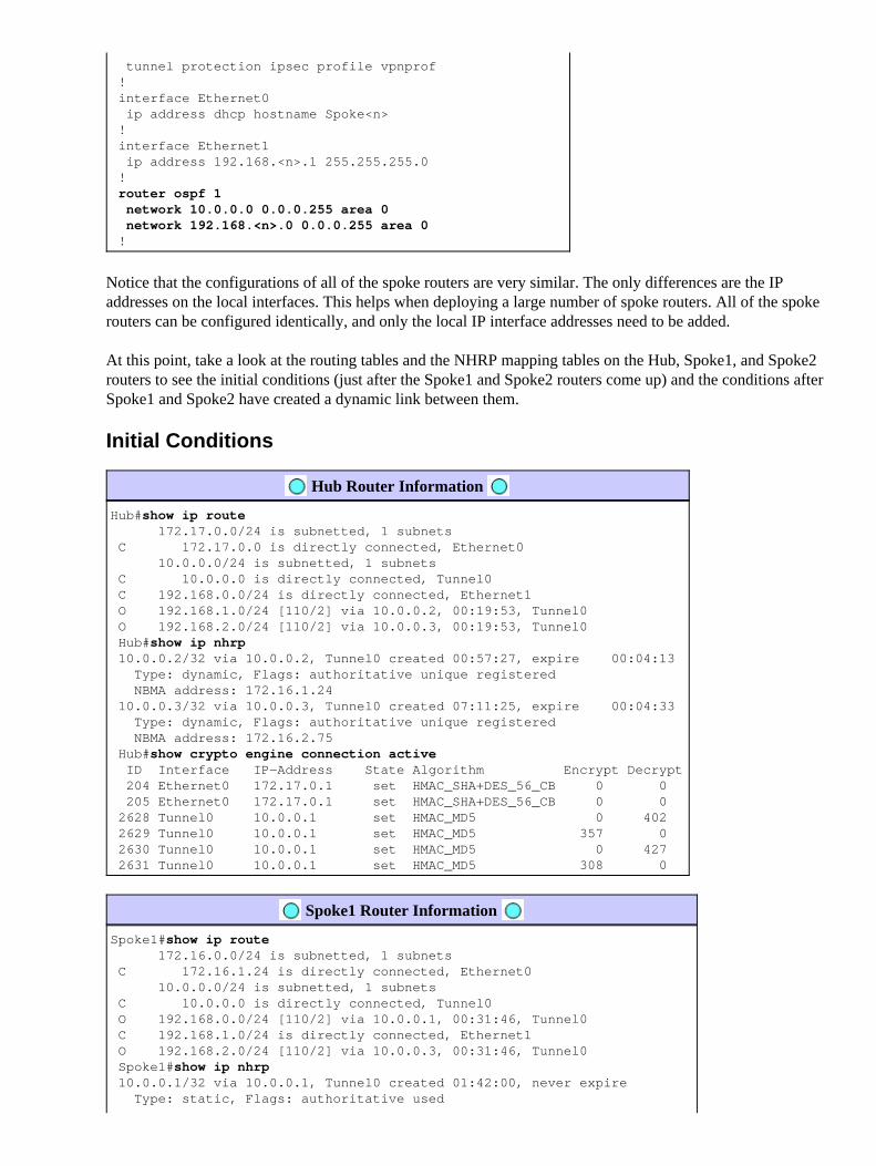
Notice that the configurations of all of the spoke routers are very similar. The only differences are the IPaddresses on the local interfaces. This helps when deploying a large number of spoke routers. All of the spokerouters can be configured identically, and only the local IP interface addresses need to be added.
At this point, take a look at the routing tables and the NHRP mapping tables on the Hub, Spoke1, and Spoke2routers to see the initial conditions (just after the Spoke1 and Spoke2 routers come up) and the conditions afterSpoke1 and Spoke2 have created a dynamic link between them.
Initial Conditions
Hub Router Information
Hub#show ip route 172.17.0.0/24 is subnetted, 1 subnets C 172.17.0.0 is directly connected, Ethernet0 10.0.0.0/24 is subnetted, 1 subnets C 10.0.0.0 is directly connected, Tunnel0 C 192.168.0.0/24 is directly connected, Ethernet1 O 192.168.1.0/24 [110/2] via 10.0.0.2, 00:19:53, Tunnel0 O 192.168.2.0/24 [110/2] via 10.0.0.3, 00:19:53, Tunnel0 Hub#show ip nhrp 10.0.0.2/32 via 10.0.0.2, Tunnel0 created 00:57:27, expire 00:04:13 Type: dynamic, Flags: authoritative unique registered NBMA address: 172.16.1.24 10.0.0.3/32 via 10.0.0.3, Tunnel0 created 07:11:25, expire 00:04:33 Type: dynamic, Flags: authoritative unique registered NBMA address: 172.16.2.75 Hub#show crypto engine connection active ID Interface IP−Address State Algorithm Encrypt Decrypt 204 Ethernet0 172.17.0.1 set HMAC_SHA+DES_56_CB 0 0 205 Ethernet0 172.17.0.1 set HMAC_SHA+DES_56_CB 0 0 2628 Tunnel0 10.0.0.1 set HMAC_MD5 0 402 2629 Tunnel0 10.0.0.1 set HMAC_MD5 357 0 2630 Tunnel0 10.0.0.1 set HMAC_MD5 0 427 2631 Tunnel0 10.0.0.1 set HMAC_MD5 308 0
Spoke1 Router Information
Spoke1#show ip route 172.16.0.0/24 is subnetted, 1 subnets C 172.16.1.24 is directly connected, Ethernet0 10.0.0.0/24 is subnetted, 1 subnets C 10.0.0.0 is directly connected, Tunnel0 O 192.168.0.0/24 [110/2] via 10.0.0.1, 00:31:46, Tunnel0 C 192.168.1.0/24 is directly connected, Ethernet1 O 192.168.2.0/24 [110/2] via 10.0.0.3, 00:31:46, Tunnel0 Spoke1#show ip nhrp 10.0.0.1/32 via 10.0.0.1, Tunnel0 created 01:42:00, never expire Type: static, Flags: authoritative used

NBMA address: 172.17.0.1 Spoke1#show crypto engine connection active ID Interface IP−Address State Algorithm Encrypt Decrypt 2 Ethernet0 172.16.1.24 set HMAC_SHA+DES_56_CB 0 0 2064 Tunnel0 10.0.0.2 set HMAC_MD5 0 244 2065 Tunnel0 10.0.0.2 set HMAC_MD5 276 0
Spoke2 Router Information
Spoke2#show ip route 172.16.0.0/24 is subnetted, 1 subnets C 172.16.2.0 is directly connected, Ethernet0 10.0.0.0/24 is subnetted, 1 subnets C 10.0.0.0 is directly connected, Tunnel0 O 192.168.0.0/24 [110/2] via 10.0.0.1, 00:38:52, Tunnel0 O 192.168.1.0/24 [110/2] via 10.0.0.2, 00:38:52, Tunnel0 C 192.168.2.0/24 is directly connected, Ethernet1 Spoke2#show ip nhrp 10.0.0.1/32 via 10.0.0.1, Tunnel0 created 01:32:10, never expire Type: static, Flags: authoritative used NBMA address: 172.17.0.1 Spoke2#show crypto engine connection active ID Interface IP−Address State Algorithm Encrypt Decrypt 17 Ethernet0 172.16.2.75 set HMAC_SHA+DES_56_CB 0 0 2070 Tunnel0 10.0.0.3 set HMAC_MD5 0 279 2071 Tunnel0 10.0.0.3 set HMAC_MD5 316 0
At this point we ping from 192.168.1.2 to 192.168.2.3. These addresses are for hosts behind the Spoke1 andSpoke2 routers, respectively. The following sequence of events takes place to build the direct spoke−to−spokemGRE+IPsec tunnel.
The Spoke1 router receives the ping packet with the destination 192.168.2.3. It looks up thisdestination in the routing table and finds that it needs to forward this packet out the Tunnel0 interfaceto the IP nexthop, 10.0.0.3.
1.
The Spoke1 router checks the NHRP mapping table for the destination 10.0.0.3 and finds that there isnot an entry. The Spoke1 router creates an NHRP resolution request packet and sends it to its NHS(the Hub router).
2.
The Hub router checks its NHRP mapping table for the destination 10.0.0.3 and finds that it maps tothe address 172.16.2.75. The Hub router creates an NHRP resolution reply packet and sends it to theSpoke1 router.
3.
The Spoke1 router receives the NHRP resolution reply, and it enters the 10.0.0.3 �>172.16.2.75mapping in its NHRP mapping table. The addition of the NHRP mapping triggers IPsec to initiate anIPsec tunnel with the peer 172.16.2.75.
4.
The Spoke1 router initiates ISAKMP with 172.16.2.75 and negotiates the ISAKMP and IPsec SAs.The IPsec proxy is derived from the Tunnel0 tunnel source <address> command and the NHRPmapping.
local ident (addr/mask/prot/port): (172.16.1.24/255.255.255.255/47/0)remote ident (addr/mask/prot/port): (172.16.2.75/255.255.255.255/47/0)
5.
Once the IPsec tunnel has finished being built, all further data packets to the 192.168.2.0/24 subnetare sent directly to Spoke2.
6.
After a packet destined to 192.168.2.3 has been forwarded to the host, this host will send a returnpacket to 192.168.1.2. When the Spoke2 router receives this packet destined to 192.168.1.2, it willlook up this destination in the routing table and find that it needs to forward this packet out theTunnel0 interface to the IP next−hop, 10.0.0.2.
7.
The Spoke2 router checks the NHRP mapping table for the destination 10.0.0.2 and finds that there isnot an entry. The Spoke2 router creates an NHRP resolution request packet and sends it to its NHS(the Hub router).
8.

The Hub router checks its NHRP mapping table for the destination 10.0.0.2 and finds that it maps tothe address 172.16.1.24. The Hub router creates an NHRP resolution reply packet and sends it to theSpoke2 router.
9.
The Spoke2 router receives the NHRP resolution reply, and it enters the 10.0.0.2 �> 172.16.1.24mapping in its NHRP mapping table. The addition of the NHRP mapping triggers IPsec to initiate anIPsec tunnel with the peer 172.16.1.24, but there already is an IPsec tunnel with peer 172.16.1.24, sonothing further needs to be done.
10.
Spoke1 and Spoke2 can now forward packets directly to each other. When the NHRP mapping hasnot been used for forwarding packets for the holdtime, the NHRP mapping will be deleted. Thedeletion of the NHRP mapping entry will trigger IPsec to delete the IPsec SAs for this direct link.
11.
Conditions After a Dynamic Link Is Created Between Spoke1 and Spoke2
Spoke1 Router Information
Spoke1#show ip nhrp 10.0.0.1/32 via 10.0.0.1, Tunnel0 created 02:34:16, never expire Type: static, Flags: authoritative used NBMA address: 172.17.0.1 10.0.0.3/32 via 10.0.0.3, Tunnel0 created 00:00:05, expire 00:03:35 Type: dynamic, Flags: router unique used NBMA address: 172.16.2.75 Spoke1#show crypto engine connection active ID Interface IP−Address State Algorithm Encrypt Decrypt 2 Ethernet0 172.16.1.24 set HMAC_SHA+DES_56_CB 0 0 3 Ethernet0 172.16.1.24 set HMAC_SHA+DES_56_CB 0 0 2064 Tunnel0 10.0.0.2 set HMAC_MD5 0 375 2065 Tunnel0 10.0.0.2 set HMAC_MD5 426 0 2066 Tunnel0 10.0.0.2 set HMAC_MD5 0 20 2067 Tunnel0 10.0.0.2 set HMAC_MD5 19 0
Spoke2 Router Information
Spoke2#show ip nhrp 10.0.0.1/32 via 10.0.0.1, Tunnel0 created 02:18:25, never expire Type: static, Flags: authoritative used NBMA address: 172.17.0.1 10.0.0.2/32 via 10.0.0.2, Tunnel0 created 00:00:24, expire 00:04:35 Type: dynamic, Flags: router unique used NBMA address: 172.16.1.24 Spoke2#show crypto engine connection active ID Interface IP−Address State Algorithm Encrypt Decrypt 17 Ethernet0 172.16.2.75 set HMAC_SHA+DES_56_CB 0 0 18 Ethernet0 172.16.2.75 set HMAC_SHA+DES_56_CB 0 0 2070 Tunnel0 10.0.0.3 set HMAC_MD5 0 407 2071 Tunnel0 10.0.0.3 set HMAC_MD5 460 0 2072 Tunnel0 10.0.0.3 set HMAC_MD5 0 19 2073 Tunnel0 10.0.0.3 set HMAC_MD5 20 0
From the above output you can see that Spoke1 and Spoke2 have gotten NHRP mappings for each other fromthe Hub router, and they have built and used an mGRE+IPsec tunnel. The NHRP mappings will expire afterfive minutes ( the current value of NHRP holdtime = 300 seconds). If the NHRP mappings are used within thelast minute before expiring, then an NHRP resolution request and reply will be sent to refresh the entry beforeit is deleted. Otherwise, the NHRP mapping will be deleted and that will trigger IPsec to clear the IPsec SAs.
Dynamic Multipoint IPsec VPN with Dual Hubs
With a few additional configuration lines to the spoke routers you can set up dual (or multiple) hub routers,for redundancy. There are two ways to configure dual hub DMVPNs.
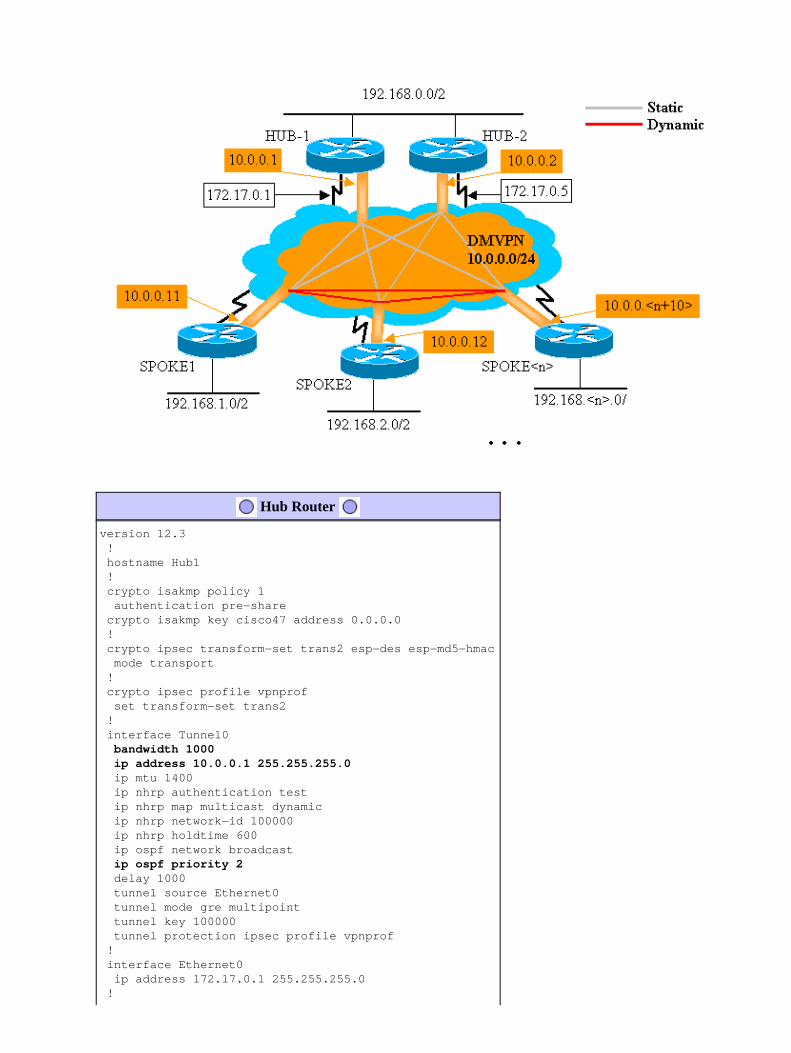
A single DMVPN network with each spoke using a single multipoint GRE tunnel interface andpointing to two different hubs as its Next−Hop−Server (NHS).
The hub routers will only have a single multipoint GRE tunnel interface.
•
Dual DMVPN networks with each spoke having two GRE tunnel interfaces (either point−to−point ormultipoint) and each GRE tunnel connected to a different hub router.
Again, the hub routers will only have a single multipoint GRE tunnel interface.
•
The following examples will look at configuring these two different scenarios for dual hub DMVPNs. In bothcases, the highlighted differences are relative to the DMVPN single hub configuration.
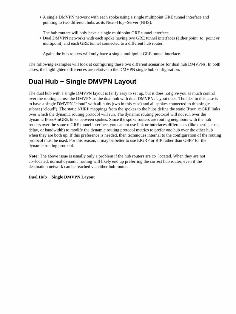
Dual Hub − Single DMVPN Layout
The dual hub with a single DMVPN layout is fairly easy to set up, but it does not give you as much controlover the routing across the DMVPN as the dual hub with dual DMVPNs layout does. The idea in this case isto have a single DMVPN "cloud" with all hubs (two in this case) and all spokes connected to this singlesubnet ("cloud"). The static NHRP mappings from the spokes to the hubs define the static IPsec+mGRE linksover which the dynamic routing protocol will run. The dynamic routing protocol will not run over thedynamic IPsec+mGRE links between spokes. Since the spoke routers are routing neighbors with the hubrouters over the same mGRE tunnel interface, you cannot use link or interfaces differences (like metric, cost,delay, or bandwidth) to modify the dynamic routing protocol metrics to prefer one hub over the other hubwhen they are both up. If this preference is needed, then techniques internal to the configuration of the routingprotocol must be used. For this reason, it may be better to use EIGRP or RIP rather than OSPF for thedynamic routing protocol.
Note: The above issue is usually only a problem if the hub routers are co−located. When they are notco−located, normal dynamic routing will likely end up preferring the correct hub router, even if thedestination network can be reached via either hub router.
Dual Hub − Single DMVPN Layout
Hub Router
version 12.3 ! hostname Hub1 ! crypto isakmp policy 1 authentication pre−share crypto isakmp key cisco47 address 0.0.0.0 ! crypto ipsec transform−set trans2 esp−des esp−md5−hmac mode transport ! crypto ipsec profile vpnprof set transform−set trans2 ! interface Tunnel0
bandwidth 1000 ip address 10.0.0.1 255.255.255.0 ip mtu 1400 ip nhrp authentication test ip nhrp map multicast dynamic ip nhrp network−id 100000 ip nhrp holdtime 600 ip ospf network broadcast
ip ospf priority 2 delay 1000 tunnel source Ethernet0 tunnel mode gre multipoint tunnel key 100000 tunnel protection ipsec profile vpnprof ! interface Ethernet0 ip address 172.17.0.1 255.255.255.0 !
interface Ethernet1 ip address 192.168.0.1 255.255.255.0 !
router ospf 1 network 10.0.0.0 0.0.0.255 area 1 network 192.168.0.0 0.0.0.255 area 0 !
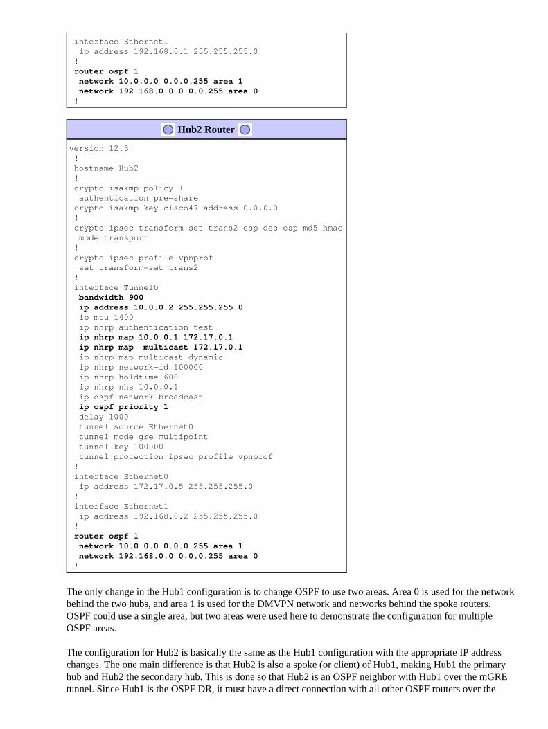
Hub2 Router
version 12.3 ! hostname Hub2 ! crypto isakmp policy 1 authentication pre−share crypto isakmp key cisco47 address 0.0.0.0 ! crypto ipsec transform−set trans2 esp−des esp−md5−hmac mode transport ! crypto ipsec profile vpnprof set transform−set trans2 ! interface Tunnel0
bandwidth 900 ip address 10.0.0.2 255.255.255.0 ip mtu 1400 ip nhrp authentication test
ip nhrp map 10.0.0.1 172.17.0.1 ip nhrp map multicast 172.17.0.1 ip nhrp map multicast dynamic ip nhrp network−id 100000 ip nhrp holdtime 600 ip nhrp nhs 10.0.0.1 ip ospf network broadcast
ip ospf priority 1 delay 1000 tunnel source Ethernet0 tunnel mode gre multipoint tunnel key 100000 tunnel protection ipsec profile vpnprof ! interface Ethernet0 ip address 172.17.0.5 255.255.255.0 ! interface Ethernet1 ip address 192.168.0.2 255.255.255.0 !
router ospf 1 network 10.0.0.0 0.0.0.255 area 1 network 192.168.0.0 0.0.0.255 area 0 !
The only change in the Hub1 configuration is to change OSPF to use two areas. Area 0 is used for the networkbehind the two hubs, and area 1 is used for the DMVPN network and networks behind the spoke routers.OSPF could use a single area, but two areas were used here to demonstrate the configuration for multipleOSPF areas.
The configuration for Hub2 is basically the same as the Hub1 configuration with the appropriate IP addresschanges. The one main difference is that Hub2 is also a spoke (or client) of Hub1, making Hub1 the primaryhub and Hub2 the secondary hub. This is done so that Hub2 is an OSPF neighbor with Hub1 over the mGREtunnel. Since Hub1 is the OSPF DR, it must have a direct connection with all other OSPF routers over the
mGRE interface (NBMA network). Without the direct link between Hub1 and Hub2, Hub2 would notparticipate in the OSPF routing when Hub1 is also up. When Hub1 is down, Hub2 will be the OSPF DR forthe DMVPN (NBMA network). When Hub1 comes back up, it will take over being the OSPF DR for theDMVPN.
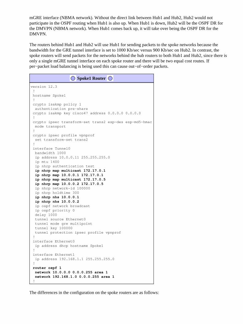
The routers behind Hub1 and Hub2 will use Hub1 for sending packets to the spoke networks because thebandwidth for the GRE tunnel interface is set to 1000 Kb/sec versus 900 Kb/sec on Hub2. In contrast, thespoke routers will send packets for the networks behind the hub routers to both Hub1 and Hub2, since there isonly a single mGRE tunnel interface on each spoke router and there will be two equal cost routes. Ifper−packet load balancing is being used this can cause out−of−order packets.
Spoke1 Router
version 12.3 ! hostname Spoke1 ! crypto isakmp policy 1 authentication pre−share crypto isakmp key cisco47 address 0.0.0.0 0.0.0.0 ! crypto ipsec transform−set trans2 esp−des esp−md5−hmac mode transport ! crypto ipsec profile vpnprof set transform−set trans2 ! interface Tunnel0 bandwidth 1000 ip address 10.0.0.11 255.255.255.0 ip mtu 1400 ip nhrp authentication test
ip nhrp map multicast 172.17.0.1 ip nhrp map 10.0.0.1 172.17.0.1 ip nhrp map multicast 172.17.0.5 ip nhrp map 10.0.0.2 172.17.0.5 ip nhrp network−id 100000 ip nhrp holdtime 300
ip nhrp nhs 10.0.0.1 ip nhrp nhs 10.0.0.2 ip ospf network broadcast ip ospf priority 0 delay 1000 tunnel source Ethernet0 tunnel mode gre multipoint tunnel key 100000 tunnel protection ipsec profile vpnprof ! interface Ethernet0 ip address dhcp hostname Spoke1 ! interface Ethernet1 ip address 192.168.1.1 255.255.255.0 !
router ospf 1 network 10.0.0.0 0.0.0.255 area 1 network 192.168.1.0 0.0.0.255 area 1 !
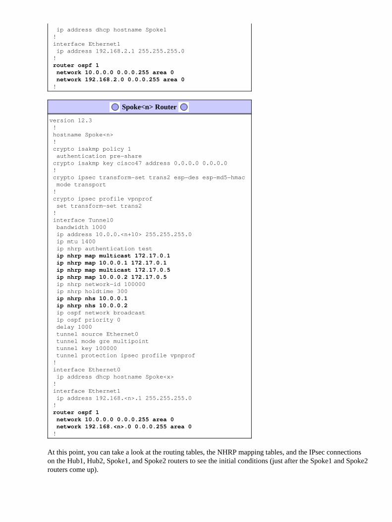
The differences in the configuration on the spoke routers are as follows:

In the new configuration, the spoke is configured with static NHRP mappings for Hub2 and Hub2 isadded as a next hop server.
Original:
ip nhrp map multicast 172.17.0.1ip nhrp map 10.0.0.1 172.17.0.1ip nhrp nhs 10.0.0.1
New:
ip nhrp map multicast 172.17.0.1ip nhrp map 10.0.0.1 172.17.0.1ip nhrp map multicast 172.17.0.5ip nhrp map 10.0.0.2 172.17.0.5ip nhrp nhs 10.0.0.1ip nhrp nhs 10.0.0.2
•
The OSPF areas on the spoke routers have been changed to area 1.•
Remember that by defining the static NHRP mapping and NHS on a spoke router for a hub, you are going torun the dynamic routing protocol over this tunnel. This defines the hub and spoke routing or neighbornetwork. Notice that Hub2 is a hub for all of the spokes, and it is also a spoke for Hub1. This makes it easy todesign, configure, and modify multilayer hub−and−spoke networks when you are using the DMVPN solution.
Spoke2 Router
version 12.3 ! hostname Spoke2 ! crypto isakmp policy 1 authentication pre−share crypto isakmp key cisco47 address 0.0.0.0 0.0.0.0 ! crypto ipsec transform−set trans2 esp−des esp−md5−hmac mode transport ! crypto ipsec profile vpnprof set transform−set trans2 ! interface Tunnel0 bandwidth 1000 ip address 10.0.0.12 255.255.255.0 ip mtu 1400 ip nhrp authentication test
ip nhrp map multicast 172.17.0.1 ip nhrp map 10.0.0.1 172.17.0.1 ip nhrp map multicast 172.17.0.5 ip nhrp map 10.0.0.2 172.17.0.5 ip nhrp network−id 100000 ip nhrp holdtime 300
ip nhrp nhs 10.0.0.1 ip nhrp nhs 10.0.0.2 ip ospf network broadcast ip ospf priority 0 delay 1000 tunnel source Ethernet0 tunnel mode gre multipoint tunnel key 100000 tunnel protection ipsec profile vpnprof ! interface Ethernet0
ip address dhcp hostname Spoke1 ! interface Ethernet1 ip address 192.168.2.1 255.255.255.0 !
router ospf 1 network 10.0.0.0 0.0.0.255 area 0 network 192.168.2.0 0.0.0.255 area 0 !
Spoke<n> Router
version 12.3 ! hostname Spoke<n> ! crypto isakmp policy 1 authentication pre−share crypto isakmp key cisco47 address 0.0.0.0 0.0.0.0 ! crypto ipsec transform−set trans2 esp−des esp−md5−hmac mode transport ! crypto ipsec profile vpnprof set transform−set trans2 ! interface Tunnel0 bandwidth 1000 ip address 10.0.0.<n+10> 255.255.255.0 ip mtu 1400 ip nhrp authentication test
ip nhrp map multicast 172.17.0.1 ip nhrp map 10.0.0.1 172.17.0.1 ip nhrp map multicast 172.17.0.5 ip nhrp map 10.0.0.2 172.17.0.5 ip nhrp network−id 100000 ip nhrp holdtime 300
ip nhrp nhs 10.0.0.1 ip nhrp nhs 10.0.0.2 ip ospf network broadcast ip ospf priority 0 delay 1000 tunnel source Ethernet0 tunnel mode gre multipoint tunnel key 100000 tunnel protection ipsec profile vpnprof ! interface Ethernet0 ip address dhcp hostname Spoke<x> ! interface Ethernet1 ip address 192.168.<n>.1 255.255.255.0 !
router ospf 1 network 10.0.0.0 0.0.0.255 area 0 network 192.168.<n>.0 0.0.0.255 area 0 !
At this point, you can take a look at the routing tables, the NHRP mapping tables, and the IPsec connectionson the Hub1, Hub2, Spoke1, and Spoke2 routers to see the initial conditions (just after the Spoke1 and Spoke2routers come up).
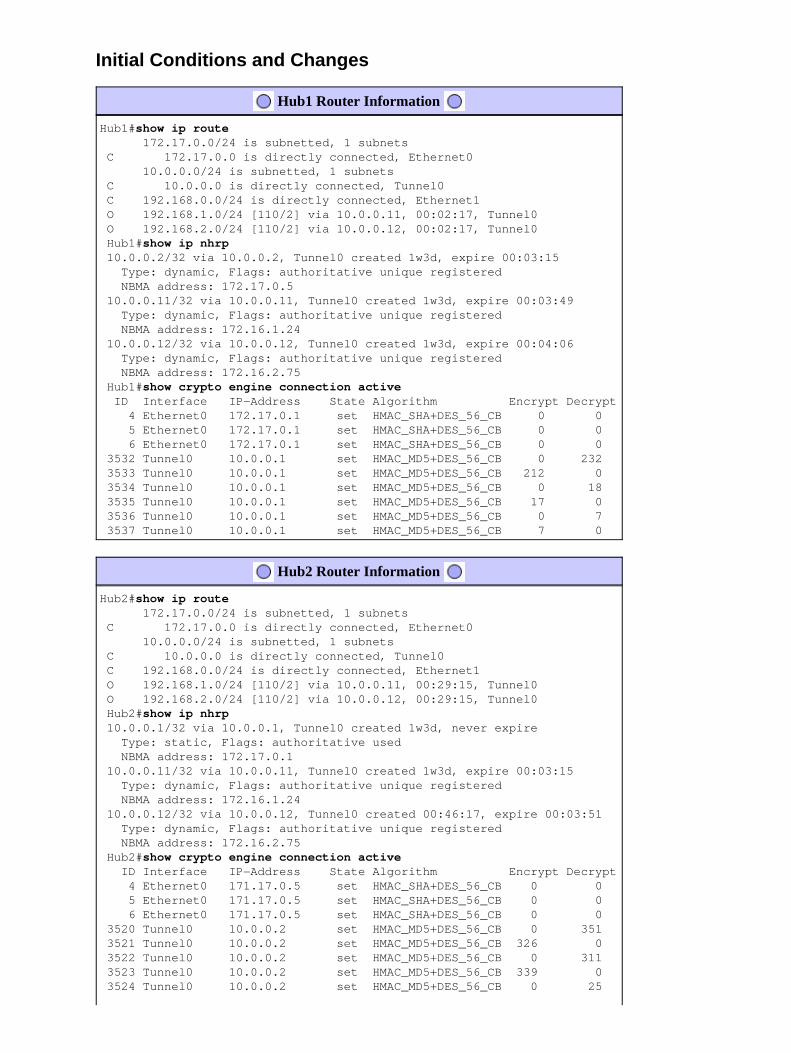
Initial Conditions and Changes
Hub1 Router Information
Hub1#show ip route 172.17.0.0/24 is subnetted, 1 subnets C 172.17.0.0 is directly connected, Ethernet0 10.0.0.0/24 is subnetted, 1 subnets C 10.0.0.0 is directly connected, Tunnel0 C 192.168.0.0/24 is directly connected, Ethernet1 O 192.168.1.0/24 [110/2] via 10.0.0.11, 00:02:17, Tunnel0 O 192.168.2.0/24 [110/2] via 10.0.0.12, 00:02:17, Tunnel0 Hub1#show ip nhrp 10.0.0.2/32 via 10.0.0.2, Tunnel0 created 1w3d, expire 00:03:15 Type: dynamic, Flags: authoritative unique registered NBMA address: 172.17.0.5 10.0.0.11/32 via 10.0.0.11, Tunnel0 created 1w3d, expire 00:03:49 Type: dynamic, Flags: authoritative unique registered NBMA address: 172.16.1.24 10.0.0.12/32 via 10.0.0.12, Tunnel0 created 1w3d, expire 00:04:06 Type: dynamic, Flags: authoritative unique registered NBMA address: 172.16.2.75 Hub1#show crypto engine connection active ID Interface IP−Address State Algorithm Encrypt Decrypt 4 Ethernet0 172.17.0.1 set HMAC_SHA+DES_56_CB 0 0 5 Ethernet0 172.17.0.1 set HMAC_SHA+DES_56_CB 0 0 6 Ethernet0 172.17.0.1 set HMAC_SHA+DES_56_CB 0 0 3532 Tunnel0 10.0.0.1 set HMAC_MD5+DES_56_CB 0 232 3533 Tunnel0 10.0.0.1 set HMAC_MD5+DES_56_CB 212 0 3534 Tunnel0 10.0.0.1 set HMAC_MD5+DES_56_CB 0 18 3535 Tunnel0 10.0.0.1 set HMAC_MD5+DES_56_CB 17 0 3536 Tunnel0 10.0.0.1 set HMAC_MD5+DES_56_CB 0 7 3537 Tunnel0 10.0.0.1 set HMAC_MD5+DES_56_CB 7 0
Hub2 Router Information
Hub2#show ip route 172.17.0.0/24 is subnetted, 1 subnets C 172.17.0.0 is directly connected, Ethernet0 10.0.0.0/24 is subnetted, 1 subnets C 10.0.0.0 is directly connected, Tunnel0 C 192.168.0.0/24 is directly connected, Ethernet1 O 192.168.1.0/24 [110/2] via 10.0.0.11, 00:29:15, Tunnel0 O 192.168.2.0/24 [110/2] via 10.0.0.12, 00:29:15, Tunnel0 Hub2#show ip nhrp 10.0.0.1/32 via 10.0.0.1, Tunnel0 created 1w3d, never expire Type: static, Flags: authoritative used NBMA address: 172.17.0.1 10.0.0.11/32 via 10.0.0.11, Tunnel0 created 1w3d, expire 00:03:15 Type: dynamic, Flags: authoritative unique registered NBMA address: 172.16.1.24 10.0.0.12/32 via 10.0.0.12, Tunnel0 created 00:46:17, expire 00:03:51 Type: dynamic, Flags: authoritative unique registered NBMA address: 172.16.2.75 Hub2#show crypto engine connection active ID Interface IP−Address State Algorithm Encrypt Decrypt 4 Ethernet0 171.17.0.5 set HMAC_SHA+DES_56_CB 0 0 5 Ethernet0 171.17.0.5 set HMAC_SHA+DES_56_CB 0 0 6 Ethernet0 171.17.0.5 set HMAC_SHA+DES_56_CB 0 0 3520 Tunnel0 10.0.0.2 set HMAC_MD5+DES_56_CB 0 351 3521 Tunnel0 10.0.0.2 set HMAC_MD5+DES_56_CB 326 0 3522 Tunnel0 10.0.0.2 set HMAC_MD5+DES_56_CB 0 311 3523 Tunnel0 10.0.0.2 set HMAC_MD5+DES_56_CB 339 0 3524 Tunnel0 10.0.0.2 set HMAC_MD5+DES_56_CB 0 25

3525 Tunnel0 10.0.0.2 set HMAC_MD5+DES_56_CB 22 0
Spoke1 Router Information
Spoke1#show ip route 172.16.0.0/24 is subnetted, 1 subnets C 172.16.1.0 is directly connected, Ethernet0 10.0.0.0/24 is subnetted, 1 subnets C 10.0.0.0 is directly connected, Tunnel0 O IA 192.168.0.0/24 [110/11] via 10.0.0.1, 00:39:31, Tunnel0 [110/11] via 10.0.0.2, 00:39:31, Tunnel0 C 192.168.1.0/24 is directly connected, Ethernet1 O 192.168.2.0/24 [110/2] via 10.0.0.12, 00:37:58, Tunnel0 Spoke1#show ip nhrp 10.0.0.1/32 via 10.0.0.1, Tunnel0 created 00:56:40, never expire Type: static, Flags: authoritative used NBMA address: 172.17.0.1 10.0.0.2/32 via 10.0.0.2, Tunnel0 created 00:56:40, never expire Type: static, Flags: authoritative used NBMA address: 172.17.0.5 Spoke1#show crypto engine connection active ID Interface IP−Address State Algorithm Encrypt Decrypt 1 Ethernet0 172.16.1.24 set HMAC_SHA+DES_56_CB 0 0 2 Ethernet0 172.16.1.24 set HMAC_SHA+DES_56_CB 0 0 2010 Tunnel0 10.0.0.11 set HMAC_MD5+DES_56_CB 0 171 2011 Tunnel0 10.0.0.11 set HMAC_MD5+DES_56_CB 185 0 2012 Tunnel0 10.0.0.11 set HMAC_MD5+DES_56_CB 0 12 2013 Tunnel0 10.0.0.11 set HMAC_MD5+DES_56_CB 13 0
Spoke2 Router Information
Spoke2#show ip route 172.16.0.0/24 is subnetted, 1 subnets C 172.16.2.0 is directly connected, Ethernet0 10.0.0.0/24 is subnetted, 1 subnets C 10.0.0.0 is directly connected, Tunnel0 O IA 192.168.0.0/24 [110/11] via 10.0.0.1, 00:57:56, Tunnel0 [110/11] via 10.0.0.2, 00:57:56, Tunnel0 O 192.168.1.0/24 [110/2] via 10.0.0.11, 00:56:14, Tunnel0 C 192.168.2.0/24 is directly connected, Ethernet1 Spoke2#show ip nhrp 10.0.0.1/32 via 10.0.0.1, Tunnel0 created 5w6d, never expire Type: static, Flags: authoritative used NBMA address: 172.17.0.1 10.0.0.2/32 via 10.0.0.2, Tunnel0 created 6w6d, never expire Type: static, Flags: authoritative used NBMA address: 172.17.0.5 Spoke2#show crypto engine connection active ID Interface IP−Address State Algorithm Encrypt Decrypt 2 Ethernet0 172.16.2.75 set HMAC_SHA+DES_56_CB 0 0 3 Ethernet0 172.16.2.75 set HMAC_SHA+DES_56_CB 0 0 3712 Tunnel0 10.0.0.12 set HMAC_MD5+DES_56_CB 0 302 3713 Tunnel0 10.0.0.12 set HMAC_MD5+DES_56_CB 331 0 3716 Tunnel0 10.0.0.12 set HMAC_MD5+DES_56_CB 0 216 3717 Tunnel0 10.0.0.12 set HMAC_MD5+DES_56_CB 236 0
There are a couple of interesting issues to notice about the routing tables on Hub1, Hub2, Spoke1, andSpoke2:
Both hub routers have equal cost routes to the networks behind the spoke routers.
Hub1:
•
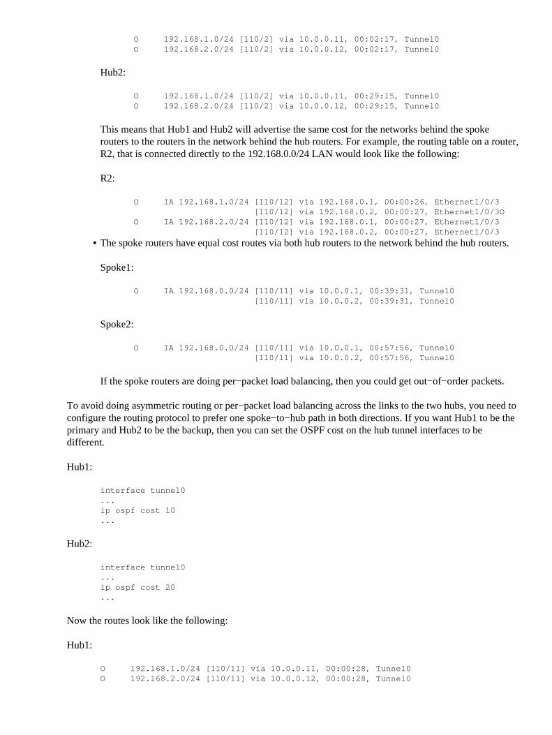
O 192.168.1.0/24 [110/2] via 10.0.0.11, 00:02:17, Tunnel0O 192.168.2.0/24 [110/2] via 10.0.0.12, 00:02:17, Tunnel0
Hub2:
O 192.168.1.0/24 [110/2] via 10.0.0.11, 00:29:15, Tunnel0O 192.168.2.0/24 [110/2] via 10.0.0.12, 00:29:15, Tunnel0
This means that Hub1 and Hub2 will advertise the same cost for the networks behind the spokerouters to the routers in the network behind the hub routers. For example, the routing table on a router,R2, that is connected directly to the 192.168.0.0/24 LAN would look like the following:
R2:
O IA 192.168.1.0/24 [110/12] via 192.168.0.1, 00:00:26, Ethernet1/0/3 [110/12] via 192.168.0.2, 00:00:27, Ethernet1/0/3OO IA 192.168.2.0/24 [110/12] via 192.168.0.1, 00:00:27, Ethernet1/0/3 [110/12] via 192.168.0.2, 00:00:27, Ethernet1/0/3
The spoke routers have equal cost routes via both hub routers to the network behind the hub routers.
Spoke1:
O IA 192.168.0.0/24 [110/11] via 10.0.0.1, 00:39:31, Tunnel0 [110/11] via 10.0.0.2, 00:39:31, Tunnel0
Spoke2:
O IA 192.168.0.0/24 [110/11] via 10.0.0.1, 00:57:56, Tunnel0 [110/11] via 10.0.0.2, 00:57:56, Tunnel0
If the spoke routers are doing per−packet load balancing, then you could get out−of−order packets.
•
To avoid doing asymmetric routing or per−packet load balancing across the links to the two hubs, you need toconfigure the routing protocol to prefer one spoke−to−hub path in both directions. If you want Hub1 to be theprimary and Hub2 to be the backup, then you can set the OSPF cost on the hub tunnel interfaces to bedifferent.
Hub1:
interface tunnel0...ip ospf cost 10...
Hub2:
interface tunnel0...ip ospf cost 20...
Now the routes look like the following:
Hub1:
O 192.168.1.0/24 [110/11] via 10.0.0.11, 00:00:28, Tunnel0O 192.168.2.0/24 [110/11] via 10.0.0.12, 00:00:28, Tunnel0

Hub2:
O 192.168.1.0/24 [110/21] via 10.0.0.11, 00:00:52, Tunnel0O 192.168.2.0/24 [110/21] via 10.0.0.12, 00:00:52, Tunnel0
R2:
O IA 192.168.1.0/24 [110/31] via 192.168.0.1, 00:01:06, Ethernet1/0/3O IA 192.168.2.0/24 [110/31] via 192.168.0.1, 00:01:06, Ethernet1/0/3
The two hub routers now have different costs on the routes for the networks behind the spoke routers. Thismeans Hub1 will be preferred for forwarding traffic to the spoke routers, as can be seen on router R2. Thiswill take care of the asymmetric routing problem described in the first bullet above.
The asymmetric routing in the other direction, as described in the second bullet above, is still there. Whenusing OSPF as the dynamic routing protocol, you can fix this with a workaround by using the distance ...command under router ospf 1 on the spokes to prefer routes learned via Hub1 over routes learned via Hub2.
Spoke1:
router ospf 1 distance 111 10.0.0.2 0.0.0.0 1access−list 1 permit any
Spoke2:
router ospf 1 distance 111 10.0.0.2 0.0.0.0 1access−list 1 permit any
Now the routes look like the following:
Spoke1:
O 192.168.0.0/24 [110/11] via 10.0.0.1, 00:00:06, Tunnel0
Spoke2:
O 192.168.1.0/24 [110/11] via 10.0.0.1, 00:00:10, Tunnel0
The above routing configuration will protect against asymmetric routing, while at the same time allowingfailover to Hub2 if Hub1 goes down. It does mean that when both hubs are up, only Hub1 is used. If you wantto use both hubs by balancing the spokes across the hubs, with failover protection and no asymmetric routing,then the routing configuration can get complex, especially when using OSPF. For this reason, the followingdual hub with dual DMVPN layout may be a better choice.
Dual Hub − Dual DMVPN Layout
The dual hub with dual DMVPN layout is slightly more difficult to set up, but it does give you better controlof the routing across the DMVPN. The idea is to have a two separate DMVPN "clouds". Each hub (two in thiscase) is connected to one DMVPN subnet ("cloud") and the spokes are connected to both DMVPN subnets("clouds"). Since the spoke routers are routing neighbors with both hub routers over the two GRE tunnelinterfaces, you can use interface configuration differences (such as bandwidth, cost and delay) to modify thedynamic routing protocol metrics to prefer one hub over the other hub when they are both up.

Note: The above issue is usually only relevant if the hub routers are co−located. When they are notco−located, normal dynamic routing will likely end up preferring the correct hub router, even if thedestination network can be reached via either hub router.
You can use either p−pGRE or mGRE tunnel interfaces on the spoke routers. Multiple p−pGRE interfaces ona spoke router can use the same tunnel source ... IP address, but multiple mGRE interfaces on a spoke routermust have a unique tunnel source ... IP address. This is because when IPsec is initiating, the first packet is anISAKMP packet which needs to be associated with one of the mGRE tunnels. The ISAKMP packet only hasthe destination IP address (remote IPsec peer address) with which to make this association. This address ismatched against the tunnel source ... address, but since both tunnels have the same tunnel source ... address,the first mGRE tunnel interface is always matched. This means that incoming multicast data packets may beassociated with the wrong mGRE interface, breaking any dynamic routing protocol.
GRE packets themselves do not have this problem since they have the tunnel key ... value to differentiatebetween the two mGRE interfaces. Starting in Cisco IOS Software Releases 12.3(5) and 12.3(7)T, anadditional parameter was introduced to overcome this limitation: tunnel protection....shared. The sharedkeyword indicates that mutiple mGRE interfaces will use the IPSec encryption with the same source IPaddress. If you have an earlier release you can use p−pGRE tunnels in this dual hub with dual DMVPNlayout. In the p−pGRE tunnel case, both the tunnel source ... and the tunnel destination ... IP addresses canbe used for matching. For this example p−pGRE tunnels will be used in this dual hub with dual DMVPNlayout and not use the shared qualifier.
Dual Hub − Dual DMVPN Layout
The following highlighted changes are relative to the dynamic multipoint hub and spoke configurationsillustrated earlier in this document.
Hub1 Router

version 12.3 !
hostname Hub1 ! crypto isakmp policy 1 authentication pre−share crypto isakmp key cisco47 address 0.0.0.0 0.0.0.0 ! crypto ipsec transform−set trans2 esp−des esp−md5−hmac mode transport ! crypto ipsec profile vpnprof set transform−set trans2 ! interface Tunnel0 bandwidth 1000 ip address 10.0.0.1 255.255.255.0 ip mtu 1400 ip nhrp authentication test ip nhrp map multicast dynamic ip nhrp network−id 100000 ip nhrp holdtime 600 no ip split−horizon eigrp 1 delay 1000 tunnel source Ethernet0 tunnel mode gre multipoint tunnel key 100000 tunnel protection ipsec profile vpnprof ! interface Ethernet0 ip address 172.17.0.1 255.255.255.252 ! interface Ethernet1 ip address 192.168.0.1 255.255.255.0 ! router eigrp 1 network 10.0.0.0 0.0.0.255 network 192.168.0.0 0.0.0.255 no auto−summary !
Hub2 Router
version 12.3 !
hostname Hub2 ! crypto isakmp policy 1 authentication pre−share crypto isakmp key cisco47 address 0.0.0.0 0.0.0.0 ! crypto ipsec transform−set trans2 esp−des esp−md5−hmac mode transport ! crypto ipsec profile vpnprof set transform−set trans2 ! interface Tunnel0 bandwidth 1000
ip address 10.0.1.1 255.255.255.0 ip mtu 1400 ip nhrp authentication test ip nhrp map multicast dynamic
ip nhrp network−id 100001 ip nhrp holdtime 600

no ip split−horizon eigrp 1 delay 1000 tunnel source Ethernet0 tunnel mode gre multipoint
tunnel key 100001 tunnel protection ipsec profile vpnprof ! interface Ethernet0 ip address 172.17.0.5 255.255.255.252 ! interface Ethernet1 ip address 192.168.0.2 255.255.255.0 ! router eigrp 1 network 10.0.1.0 0.0.0.255 network 192.168.0.0 0.0.0.255 no auto−summary !
In this case, the Hub1 and Hub2 configurations are similar. The main difference is that each is the hub of adifferent DMVPN. Each DMVPN uses a different:
IP subnet (10.0.0.0/24, 10.0.0.1/24)• NHRP network id (100000, 100001)• Tunnel key (100000, 100001)•
The dynamic routing protocol has been switched from OSPF to EIGRP, since it is easier to set up and managea NBMA network using EIGRP, as described later in this document.
Spoke1 Router
version 12.3 ! hostname Spoke1 ! crypto isakmp policy 1 authentication pre−share crypto isakmp key cisco47 address 0.0.0.0 0.0.0.0 ! crypto ipsec transform−set trans2 esp−des esp−md5−hmac mode transport ! crypto ipsec profile vpnprof set transform−set trans2 !
interface Tunnel0 bandwidth 1000
ip address 10.0.0.11 255.255.255.0 ip mtu 1400 ip nhrp authentication test
ip nhrp map 10.0.0.1 172.17.0.1 ip nhrp network−id 100000 ip nhrp holdtime 300
ip nhrp nhs 10.0.0.1 delay 1000 tunnel source Ethernet0
tunnel destination 172.17.0.1 tunnel key 100000 tunnel protection ipsec profile vpnprof !
interface Tunnel1 bandwidth 1000
ip address 10.0.1.11 255.255.255.0

ip mtu 1400 ip nhrp authentication test
ip nhrp map 10.0.1.1 172.17.0.5 ip nhrp network−id 100001 ip nhrp holdtime 300
ip nhrp nhs 10.0.1.1 delay 1000 tunnel source Ethernet0
tunnel destination 172.17.0.5 tunnel key 100001 tunnel protection ipsec profile vpnprof ! interface Ethernet0 ip address dhcp hostname Spoke1 ! interface Ethernet1 ip address 192.168.1.1 255.255.255.0 ! router eigrp 1
network 10.0.0.0 0.0.0.255 network 10.0.1.0 0.0.0.255 network 192.168.1.0 0.0.0.255 no auto−summary !
Each of the spoke routers is configured with two p−pGRE tunnel interface, one in each of the two DMVPNs.The ip address ..., ip nhrp network−id ..., tunnel key ... and tunnel destination ... values are used todifferentiate between the two tunnels. The dynamic routing protocol, EIGRP, is run over both p−pGRE tunnelsubnets and is used to select one p−pGRE interface (DMVPN) over the other.
Spoke2 Router
version 12.3 ! hostname Spoke2 ! crypto isakmp policy 1 authentication pre−share crypto isakmp key cisco47 address 0.0.0.0 0.0.0.0 ! crypto ipsec transform−set trans2 esp−des esp−md5−hmac mode transport ! crypto ipsec profile vpnprof set transform−set trans2 !
interface Tunnel0 bandwidth 1000
ip address 10.0.0.12 255.255.255.0 ip mtu 1400 ip nhrp authentication test
ip nhrp map 10.0.0.1 172.17.0.1 ip nhrp network−id 100000 ip nhrp holdtime 300
ip nhrp nhs 10.0.0.1 delay 1000 tunnel source Ethernet0
tunnel destination 172.17.0.1 tunnel key 100000 tunnel protection ipsec profile vpnprof ! interface Tunnel1 bandwidth 1000
ip address 10.0.1.12 255.255.255.0
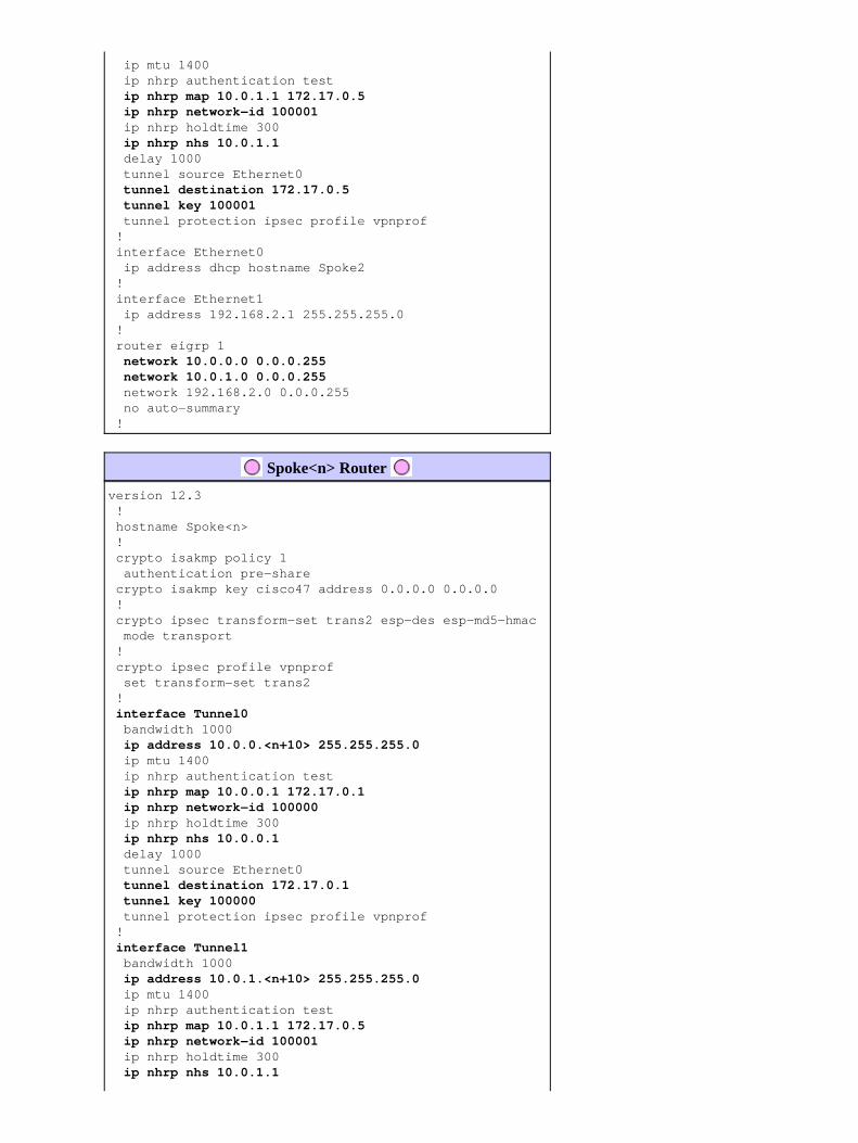
ip mtu 1400 ip nhrp authentication test
ip nhrp map 10.0.1.1 172.17.0.5 ip nhrp network−id 100001 ip nhrp holdtime 300
ip nhrp nhs 10.0.1.1 delay 1000 tunnel source Ethernet0
tunnel destination 172.17.0.5 tunnel key 100001 tunnel protection ipsec profile vpnprof ! interface Ethernet0 ip address dhcp hostname Spoke2 ! interface Ethernet1 ip address 192.168.2.1 255.255.255.0 ! router eigrp 1
network 10.0.0.0 0.0.0.255 network 10.0.1.0 0.0.0.255 network 192.168.2.0 0.0.0.255 no auto−summary !
Spoke<n> Router
version 12.3 ! hostname Spoke<n> ! crypto isakmp policy 1 authentication pre−share crypto isakmp key cisco47 address 0.0.0.0 0.0.0.0 ! crypto ipsec transform−set trans2 esp−des esp−md5−hmac mode transport ! crypto ipsec profile vpnprof set transform−set trans2 !
interface Tunnel0 bandwidth 1000
ip address 10.0.0.<n+10> 255.255.255.0 ip mtu 1400 ip nhrp authentication test
ip nhrp map 10.0.0.1 172.17.0.1 ip nhrp network−id 100000 ip nhrp holdtime 300
ip nhrp nhs 10.0.0.1 delay 1000 tunnel source Ethernet0
tunnel destination 172.17.0.1 tunnel key 100000 tunnel protection ipsec profile vpnprof !
interface Tunnel1 bandwidth 1000
ip address 10.0.1.<n+10> 255.255.255.0 ip mtu 1400 ip nhrp authentication test
ip nhrp map 10.0.1.1 172.17.0.5 ip nhrp network−id 100001 ip nhrp holdtime 300
ip nhrp nhs 10.0.1.1

delay 1000 tunnel source Ethernet0
tunnel destination 172.17.0.5 tunnel key 100001 tunnel protection ipsec profile vpnprof ! interface Ethernet0 ip address dhcp hostname Spoke<x> ! interface Ethernet1 ip address 192.168.<n>.1 255.255.255.0 ! router eigrp 1
network 10.0.0.0 0.0.0.255 network 10.0.1.0 0.0.0.255 network 192.168.<n>.0 0.0.0.255 no auto−summary !
At this point, let us take a look at the routing tables, the NHRP mapping tables, and IPsec connections on theHub1, Hub2, Spoke1 and Spoke2 routers to see the initial conditions (just after the Spoke1 and Spoke2 routerscome up).
Initial Conditions and Changes
Hub1 Router Information
Hub1#show ip route 172.17.0.0/30 is subnetted, 1 subnets C 172.17.0.0 is directly connected, Ethernet0 10.0.0.0/24 is subnetted, 2 subnets C 10.0.0.0 is directly connected, Tunnel0 D 10.0.1.0 [90/2611200] via 192.168.0.2, 00:00:46, Ethernet1 C 192.168.0.0/24 is directly connected, Ethernet1 D 192.168.1.0/24 [90/2841600] via 10.0.0.11, 00:00:59, Tunnel0 D 192.168.2.0/24 [90/2841600] via 10.0.0.12, 00:00:34, Tunnel0 Hub1#show ip nhrp 10.0.0.12/32 via 10.0.0.12, Tunnel0 created 23:48:32, expire 00:03:50 Type: dynamic, Flags: authoritative unique registered NBMA address: 172.16.2.75 10.0.0.11/32 via 10.0.0.11, Tunnel0 created 23:16:46, expire 00:04:45 Type: dynamic, Flags: authoritative unique registered NBMA address: 172.16.1.24 Hub1#show crypto engine connection active ID Interface IP−Address State Algorithm Encrypt Decrypt 15 Ethernet0 172.17.63.18 set HMAC_SHA+DES_56_CB 0 0 16 Ethernet0 10.0.0.1 set HMAC_SHA+DES_56_CB 0 0 2038 Tunnel0 10.0.0.1 set HMAC_MD5+DES_56_CB 0 759 2039 Tunnel0 10.0.0.1 set HMAC_MD5+DES_56_CB 726 0 2040 Tunnel0 10.0.0.1 set HMAC_MD5+DES_56_CB 0 37 2041 Tunnel0 10.0.0.1 set HMAC_MD5+DES_56_CB 36 0
Hub2 Router Information
Hub2#show ip route 172.17.0.0/30 is subnetted, 1 subnets C 172.17.0.4 is directly connected, Ethernet0 10.0.0.0/24 is subnetted, 2 subnets D 10.0.0.0 [90/2611200] via 192.168.0.1, 00:12:22, Ethernet1 C 10.0.1.0 is directly connected, Tunnel0 C 192.168.0.0/24 is directly connected, Ethernet1 D 192.168.1.0/24 [90/2841600] via 10.0.1.11, 00:13:24, Tunnel0 D 192.168.2.0/24 [90/2841600] via 10.0.1.12, 00:12:11, Tunnel0

Hub2#show ip nhrp 10.0.1.12/32 via 10.0.1.12, Tunnel3 created 06:03:24, expire 00:04:39 Type: dynamic, Flags: authoritative unique registered NBMA address: 172.16.2.75 10.0.1.11/32 via 10.0.1.11, Tunnel3 created 23:06:47, expire 00:04:54 Type: dynamic, Flags: authoritative unique registered NBMA address: 172.16.1.24 Hub2#show crypto engine connection active ID Interface IP−Address State Algorithm Encrypt Decrypt 4 Ethernet0 171.17.0.5 set HMAC_SHA+DES_56_CB 0 0 6 Ethernet0 171.17.0.5 set HMAC_SHA+DES_56_CB 0 0 2098 Tunnel0 10.0.1.1 set HMAC_MD5+DES_56_CB 0 722 2099 Tunnel0 10.0.1.1 set HMAC_MD5+DES_56_CB 690 0 2100 Tunnel0 10.0.1.1 set HMAC_MD5+DES_56_CB 0 268 2101 Tunnel0 10.0.1.1 set HMAC_MD5+DES_56_CB 254 0
Spoke1 Router Information
Spoke1#show ip route 172.16.0.0/24 is subnetted, 1 subnets C 172.16.1.0 is directly connected, Ethernet0 10.0.0.0/24 is subnetted, 1 subnets C 10.0.0.0 is directly connected, Tunnel0 C 10.0.1.0 is directly connected, Tunnel1 D 192.168.0.0/24 [90/2841600] via 10.0.1.1, 00:26:30, Tunnel1 [90/2841600] via 10.0.0.1, 00:26:30, Tunnel0 C 192.168.1.0/24 is directly connected, Ethernet1 D 192.168.2.0/24 [90/3097600] via 10.0.1.1, 00:26:29, Tunnel1 [90/3097600] via 10.0.0.1, 00:26:29, Tunnel0 Spoke1#show ip nhrp 10.0.0.1/32 via 10.0.0.1, Tunnel0 created 23:25:46, never expire Type: static, Flags: authoritative NBMA address: 172.17.0.1 10.0.1.1/32 via 10.0.1.1, Tunnel1 created 23:24:40, never expire Type: static, Flags: authoritative NBMA address: 172.17.0.5 Spoke1#show crypto engine connection active ID Interface IP−Address State Algorithm Encrypt Decrypt 16 Ethernet0 172.16.1.24 set HMAC_SHA+DES_56_CB 0 0 18 Ethernet0 172.16.1.24 set HMAC_SHA+DES_56_CB 0 0 2118 Tunnel0 10.0.0.11 set HMAC_MD5+DES_56_CB 0 181 2119 Tunnel0 10.0.0.11 set HMAC_MD5+DES_56_CB 186 0 2120 Tunnel1 10.0.1.11 set HMAC_MD5+DES_56_CB 0 105 2121 Tunnel1 10.0.1.11 set HMAC_MD5+DES_56_CB 110 0
Spoke2 Router Information
Spoke2#show ip route 172.16.0.0/24 is subnetted, 1 subnets C 172.16.2.0 is directly connected, Ethernet0 10.0.0.0/24 is subnetted, 2 subnets C 10.0.0.0 is directly connected, Tunnel0 C 10.0.1.0 is directly connected, Tunnel1 D 192.168.0.0/24 [90/2841600] via 10.0.1.1, 00:38:04, Tunnel1 [90/2841600] via 10.0.0.1, 00:38:04, Tunnel0 D 192.168.1.0/24 [90/3097600] via 10.0.1.1, 00:38:02, Tunnel1 [90/3097600] via 10.0.0.1, 00:38:02, Tunnel0 C 192.168.2.0/24 is directly connected, Ethernet1 Spoke2#show ip nhrp 10.0.0.1/32 via 10.0.0.1, Tunnel0 created 1d02h, never expire Type: static, Flags: authoritative used NBMA address: 172.17.0.1 10.0.1.1/32 via 10.0.1.1, Tunnel1 created 1d02h, never expire Type: static, Flags: authoritative used NBMA address: 172.17.0.5

Spoke2#show crypto engine connection active ID Interface IP−Address State Algorithm Encrypt Decrypt 8 Ethernet0 172.16.2.75 set HMAC_SHA+DES_56_CB 0 0 9 Ethernet0 172.16.2.75 set HMAC_SHA+DES_56_CB 0 0 2036 Tunnel0 10.0.0.12 set HMAC_MD5+DES_56_CB 0 585 2037 Tunnel0 10.0.0.12 set HMAC_MD5+DES_56_CB 614 0 2038 Tunnel1 10.0.1.12 set HMAC_MD5+DES_56_CB 0 408 2039 Tunnel1 10.0.1.12 set HMAC_MD5+DES_56_CB 424 0
Again, there are a couple of interesting things to notice about the routing tables on Hub1, Hub2, Spoke1, andSpoke2:
Both hub routers have equal cost routes to the networks behind the spoke routers.
Hub1:
D 192.168.1.0/24 [90/2841600] via 10.0.0.11, 00:00:59, Tunnel0D 192.168.2.0/24 [90/2841600] via 10.0.0.12, 00:00:34, Tunnel0
Hub2:
D 192.168.1.0/24 [90/2841600] via 10.0.1.11, 00:13:24, Tunnel0D 192.168.2.0/24 [90/2841600] via 10.0.1.12, 00:12:11, Tunnel0
This means that Hub1 and Hub2 will advertise the same cost for the networks behind the spokerouters to the routers in the network behind the hub routers. For example, the routing table on a router,R2, that is connected directly to the 192.168.0.0/24 LAN would look like the following:
R2:
D 192.168.1.0/24 [90/2867200] via 192.168.0.1, 00:51:51, Ethernet1/0/3 [90/2867200] via 192.168.0.2, 00:51:51, Ethernet1/0/3D 192.168.2.0/24 [90/2867200] via 192.168.0.2, 00:52:43, Ethernet1/0/3 [90/2867200] via 192.168.0.1, 00:52:43, Ethernet1/0/3
•
The spoke routers have equal cost routes via both hub routers to the network behind the hub routers.
Spoke1:
D 192.168.0.0/24 [90/3097600] via 10.0.1.1, 00:26:30, Tunnel1 [90/3097600] via 10.0.0.1, 00:26:30, Tunnel0
Spoke2:
D 192.168.0.0/24 [90/3097600] via 10.0.1.1, 00:38:04, Tunnel1 [90/3097600] via 10.0.0.1, 00:38:04, Tunnel0
If the spoke routers are doing per−packet load−balancing, then you could get out−of−order packets.
•
To avoid doing asymmetric routing or per−packet load balancing across the links to the two hubs, you need toconfigure the routing protocol to prefer one spoke−to−hub path in both directions. If you want Hub1 to be theprimary and Hub2 to be the backup, then you can set the delay on the hub tunnel interfaces to be different.
Hub1:
interface tunnel0...delay 1000...
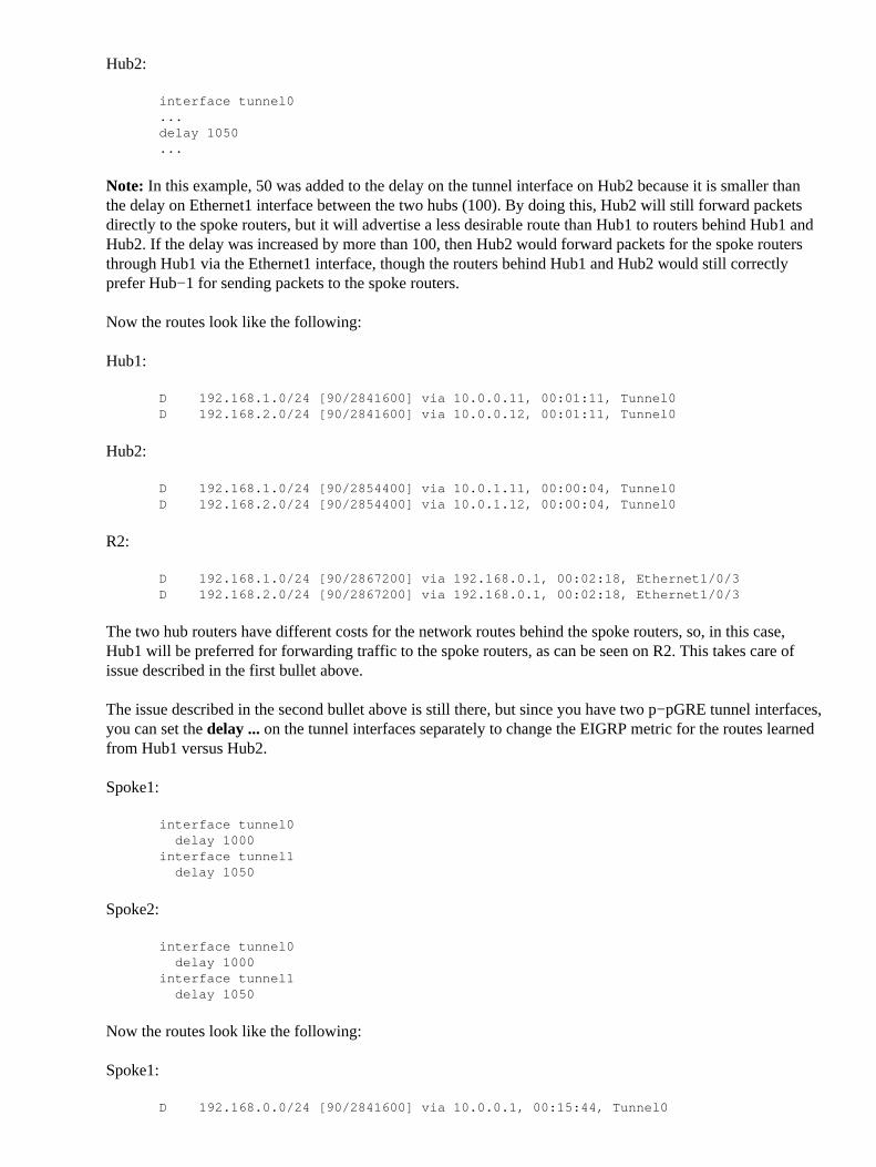
Hub2:
interface tunnel0...delay 1050...
Note: In this example, 50 was added to the delay on the tunnel interface on Hub2 because it is smaller thanthe delay on Ethernet1 interface between the two hubs (100). By doing this, Hub2 will still forward packetsdirectly to the spoke routers, but it will advertise a less desirable route than Hub1 to routers behind Hub1 andHub2. If the delay was increased by more than 100, then Hub2 would forward packets for the spoke routersthrough Hub1 via the Ethernet1 interface, though the routers behind Hub1 and Hub2 would still correctlyprefer Hub−1 for sending packets to the spoke routers.
Now the routes look like the following:
Hub1:
D 192.168.1.0/24 [90/2841600] via 10.0.0.11, 00:01:11, Tunnel0D 192.168.2.0/24 [90/2841600] via 10.0.0.12, 00:01:11, Tunnel0
Hub2:
D 192.168.1.0/24 [90/2854400] via 10.0.1.11, 00:00:04, Tunnel0D 192.168.2.0/24 [90/2854400] via 10.0.1.12, 00:00:04, Tunnel0
R2:
D 192.168.1.0/24 [90/2867200] via 192.168.0.1, 00:02:18, Ethernet1/0/3D 192.168.2.0/24 [90/2867200] via 192.168.0.1, 00:02:18, Ethernet1/0/3
The two hub routers have different costs for the network routes behind the spoke routers, so, in this case,Hub1 will be preferred for forwarding traffic to the spoke routers, as can be seen on R2. This takes care ofissue described in the first bullet above.
The issue described in the second bullet above is still there, but since you have two p−pGRE tunnel interfaces,you can set the delay ... on the tunnel interfaces separately to change the EIGRP metric for the routes learnedfrom Hub1 versus Hub2.
Spoke1:
interface tunnel0 delay 1000interface tunnel1 delay 1050
Spoke2:
interface tunnel0 delay 1000interface tunnel1 delay 1050
Now the routes look like the following:
Spoke1:
D 192.168.0.0/24 [90/2841600] via 10.0.0.1, 00:15:44, Tunnel0

D 192.168.2.0/24 [90/3097600] via 10.0.0.1, 00:15:44, Tunnel0
Spoke2:
D 192.168.0.0/24 [90/2841600] via 10.0.0.1, 00:13:54, Tunnel0D 192.168.1.0/24 [90/3097600] via 10.0.0.1, 00:13:54, Tunnel0
The above routing configuration will protect against asymmetric routing, while at the same time allowingfailover to Hub2 if Hub1 goes down. It does mean that when both hubs are up, only Hub1 is used.
If you want to use both hubs by balancing the spokes across the hubs, with failover protection and noasymmetric routing, then the routing configuration is more complex, but you can do it when using EIGRP. Toaccomplish this, set the delay ... on the tunnel interfaces of the hub routers back to being equal and then usethe offset−list <acl> out <offset> <interface> command on the spoke routers to increase the EIGRP metricfor routes advertised out the GRE tunnel interfaces to the backup hub. The unequal delay ... between theTunnel0 and Tunnel1 interfaces on the spoke is still used, so the spoke router will prefer its primary hubrouter. The changes on the spoke routers are as follows.
Spoke1 Router
version 12.3 ! hostname Spoke1 ! ... ! interface Tunnel0 bandwidth 1000 ip address 10.0.0.11 255.255.255.0 ip mtu 1400 ip nhrp authentication test ip nhrp map 10.0.0.1 172.17.0.1 ip nhrp network−id 100000 ip nhrp holdtime 300 ip nhrp nhs 10.0.0.1
delay 1000 tunnel source Ethernet0 tunnel destination 172.17.0.1 tunnel key 100000 tunnel protection ipsec profile vpnprof ! interface Tunnel1 bandwidth 1000 ip address 10.0.1.11 255.255.255.0 ip mtu 1400 ip nhrp authentication test ip nhrp map 10.0.1.1 172.17.0.5 ip nhrp network−id 100001 ip nhrp holdtime 300 ip nhrp nhs 10.0.1.1
delay 1500 tunnel source Ethernet0 tunnel destination 172.17.0.5 tunnel key 100001 tunnel protection ipsec profile vpnprof ! ... ! router eigrp 1
offset−list 1 out 12800 Tunnel1 network 10.0.0.0 0.0.0.255 network 10.0.1.0 0.0.0.255 network 192.168.1.0
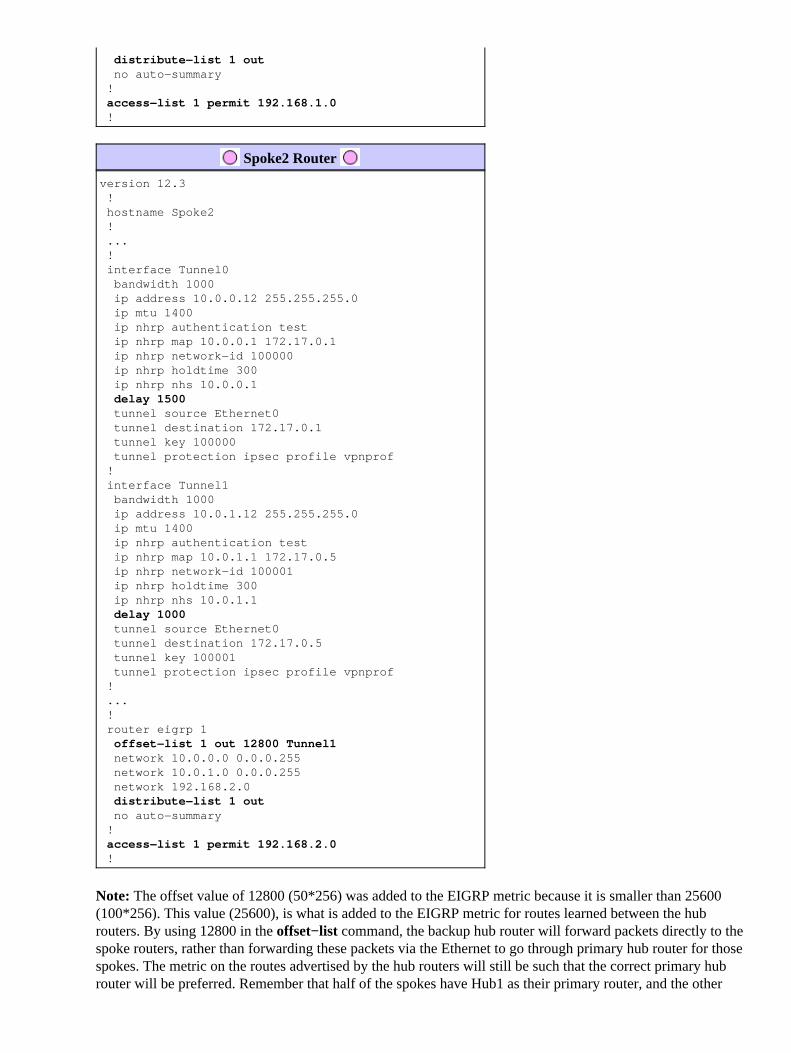
distribute−list 1 out no auto−summary !
access−list 1 permit 192.168.1.0 !
Spoke2 Router
version 12.3 ! hostname Spoke2 ! ... ! interface Tunnel0 bandwidth 1000 ip address 10.0.0.12 255.255.255.0 ip mtu 1400 ip nhrp authentication test ip nhrp map 10.0.0.1 172.17.0.1 ip nhrp network−id 100000 ip nhrp holdtime 300 ip nhrp nhs 10.0.0.1
delay 1500 tunnel source Ethernet0 tunnel destination 172.17.0.1 tunnel key 100000 tunnel protection ipsec profile vpnprof ! interface Tunnel1 bandwidth 1000 ip address 10.0.1.12 255.255.255.0 ip mtu 1400 ip nhrp authentication test ip nhrp map 10.0.1.1 172.17.0.5 ip nhrp network−id 100001 ip nhrp holdtime 300 ip nhrp nhs 10.0.1.1
delay 1000 tunnel source Ethernet0 tunnel destination 172.17.0.5 tunnel key 100001 tunnel protection ipsec profile vpnprof ! ... ! router eigrp 1
offset−list 1 out 12800 Tunnel1 network 10.0.0.0 0.0.0.255 network 10.0.1.0 0.0.0.255 network 192.168.2.0
distribute−list 1 out no auto−summary !
access−list 1 permit 192.168.2.0 !
Note: The offset value of 12800 (50*256) was added to the EIGRP metric because it is smaller than 25600(100*256). This value (25600), is what is added to the EIGRP metric for routes learned between the hubrouters. By using 12800 in the offset−list command, the backup hub router will forward packets directly to thespoke routers, rather than forwarding these packets via the Ethernet to go through primary hub router for thosespokes. The metric on the routes advertised by the hub routers will still be such that the correct primary hubrouter will be preferred. Remember that half of the spokes have Hub1 as their primary router, and the other

half have Hub2 as their primary router.
Note: If the offset value was increased by more than 25600 (100*256), then the hubs would forward packetsfor half of the spoke routers through the other hub via the Ethernet1 interface, even though the routers behindthe hubs would still prefer the correct hub for sending packets to the spoke routers.
Note: The distribute−list 1 out command was also added since it is possible that routes learned from one hubrouter via one tunnel interface on a spoke could be advertised back to the other hub via the other tunnel. Thedistribute−list ... command ensures that the spoke router can only advertise its own routes.
Note: If you prefer to control the routing advertisements on the hub routers rather than on the spoke routers ,then the offset−list <acl1> in <value> <interface> and distribute−list <acl2> in commands can beconfigured on the hub routers instead of on the spokes. The <acl2> access−list would list the routes frombehind all spokes and the <acl1> access−list would list only the routes from behind spokes where another hubrouter is to be the primary hub.
With these changes the routes look like the following:
Hub1:
D 192.168.1.0/24 [90/2841600] via 10.0.0.11, 00:12:11, Tunnel2D 192.168.2.0/24 [90/2854400] via 10.0.0.12, 00:13:24, Tunnel2
Hub2:
D 192.168.1.0/24 [90/2854400] via 10.0.1.11, 00:09:58, Tunnel0D 192.168.2.0/24 [90/2841600] via 10.10.1.12, 00:11:11, Tunnel0
R2:
D 192.168.1.0/24 [90/2867200] via 192.168.0.1, 00:13:13, Ethernet1/0/3D 192.168.2.0/24 [90/2867200] via 192.168.0.2, 00:14:25, Ethernet1/0/3
Spoke1:
D 192.168.0.0/24 [90/2841600] via 10.0.0.1, 00:16:12, Tunnel0
Spoke2:
D 192.168.0.0/24 [90/2841600] via 10.0.1.1, 00:18:54, Tunnel1
Conclusion
The DMVPN solution provides the following functionality to better scale large and small IPsec VPNnetworks.
DMVPN allows better scaling in full mesh or in partial mesh IPsec VPNs.
It is especially useful when spoke−to−spoke traffic is sporadic (for example, every spoke is notconstantly sending data to every other spoke). It does allow any spoke to send data directly to anyother spoke, as long there is direct IP connectivity between the spokes.
•
DMVPN supports IPsec nodes with dynamically assigned addresses (such as Cable, ISDN, and DSL).
This applies to hub−and−spoke as well as mesh networks. DMVPN can require the hub−to−spokelink to constantly be up.
•

DMVPN simplifies the addition of VPN nodes.
When adding a new spoke router, you only have to configure the spoke router and plug it into thenetwork (though, you may need to add ISAKMP authorization information for the new spoke on thehub). The hub will dynamically learn about the new spoke and the dynamic routing protocol willpropagate the routing to the hub and all other spokes.
•
DMVPN reduces the size of the configuration needed on all the routers in the VPN.
This is also the case for GRE+IPsec hub−and−spoke−only VPN networks.
•
DMVPN uses GRE and, therefore, supports IP multicast and dynamic routing traffic across the VPN.
This means that a dynamic routing protocol can be used, and redundant �hubs� can be supported bythe protocol. Multicast applications are also supported.
•
DMVPN supports split tunneling at the spokes.•
Related Information
Dynamic Multipoint VPN (DMVPN)• IPSec Support Page• Technical Support − Cisco Systems•
Contacts & Feedback | Help | Site Map© 2012 − 2013 Cisco Systems, Inc. All rights reserved. Terms & Conditions | Privacy Statement | Cookie Policy | Trademarks ofCisco Systems, Inc.
Updated: Jan 04, 2006 Document ID: 41940
Recommended


![Demystifying IPSec VPNs[1] - InfoSecWriters.cominfosecwriters.com/text_resources/pdf/Demystifying_IPSec_VPNs.pdf · Demystifying IPSec VPN’s 2 (21) 2 In this article I will cover](https://img.dokumen.tips/doc/110x75/5b50584e7f8b9a346e8e50e2/demystifying-ipsec-vpns1-demystifying-ipsec-vpns-2-21-2-in-this-article.jpg)