Magnetic Effects of
Electric Current
13CHAPTER
In the previous Chapter on ‘Electricity’ we learnt about the heatingeffects of electric current. What could be the other effects of electric
current? We know that an electric current-carrying wire behaves like amagnet. Let us perform the following Activity to reinforce it.
Activity 13.1Activity 13.1Activity 13.1Activity 13.1Activity 13.1
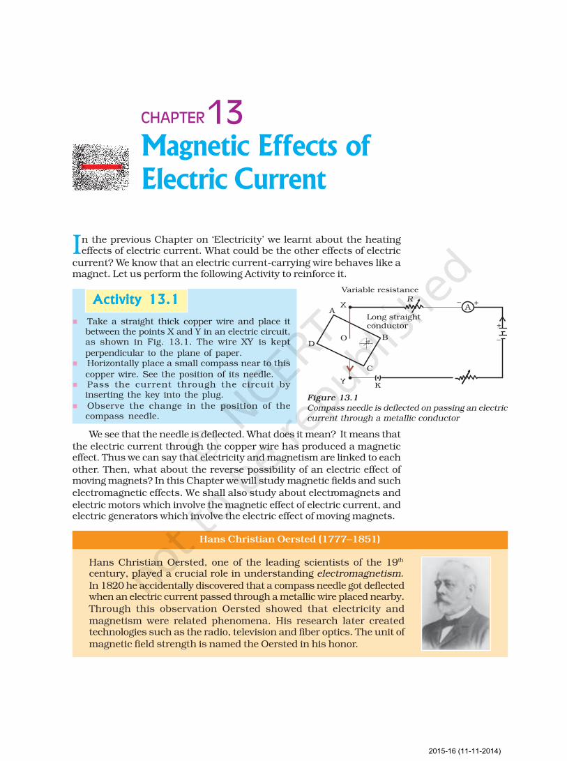
n Take a straight thick copper wire and place itbetween the points X and Y in an electric circuit,as shown in Fig. 13.1. The wire XY is kept
perpendicular to the plane of paper.n Horizontally place a small compass near to this
copper wire. See the position of its needle.n Pass the current through the circuit by
inserting the key into the plug.
n Observe the change in the position of thecompass needle.
Figure 13.1Compass needle is deflected on passing an electriccurrent through a metallic conductor
We see that the needle is deflected. What does it mean? It means that
the electric current through the copper wire has produced a magneticeffect. Thus we can say that electricity and magnetism are linked to each
other. Then, what about the reverse possibility of an electric effect ofmoving magnets? In this Chapter we will study magnetic fields and such
electromagnetic effects. We shall also study about electromagnets and
electric motors which involve the magnetic effect of electric current, andelectric generators which involve the electric effect of moving magnets.
Hans Christian Oersted (1777–1851)
Hans Christian Oersted, one of the leading scientists of the 19th
century, played a crucial role in understanding electromagnetism.
In 1820 he accidentally discovered that a compass needle got deflectedwhen an electric current passed through a metallic wire placed nearby.
Through this observation Oersted showed that electricity and
magnetism were related phenomena. His research later createdtechnologies such as the radio, television and fiber optics. The unit of
magnetic field strength is named the Oersted in his honor.
2015-16 (11-11-2014)
Science224
13.1 MAGNETIC FIELD AND FIELD LINES13.1 MAGNETIC FIELD AND FIELD LINES13.1 MAGNETIC FIELD AND FIELD LINES13.1 MAGNETIC FIELD AND FIELD LINES13.1 MAGNETIC FIELD AND FIELD LINES
We are familiar with the fact that a compass needle gets deflected when
brought near a bar magnet. A compass needle is, in fact, a small barmagnet. The ends of the compass needle point approximately towards
north and south directions. The end pointing towards north is called northseeking or north pole. The other end that points towards south is calledsouth seeking or south pole. Through various activities we have observed
that like poles repel, while unlike poles of magnets attract each other.
Q U E S T I O N
?1. Why does a compass needle get deflected when brought neara bar magnet?
Activity 13.2Activity 13.2Activity 13.2Activity 13.2Activity 13.2
n Fix a sheet of white paper on a drawing
board using some adhesive material.n Place a bar magnet in the centre of it.
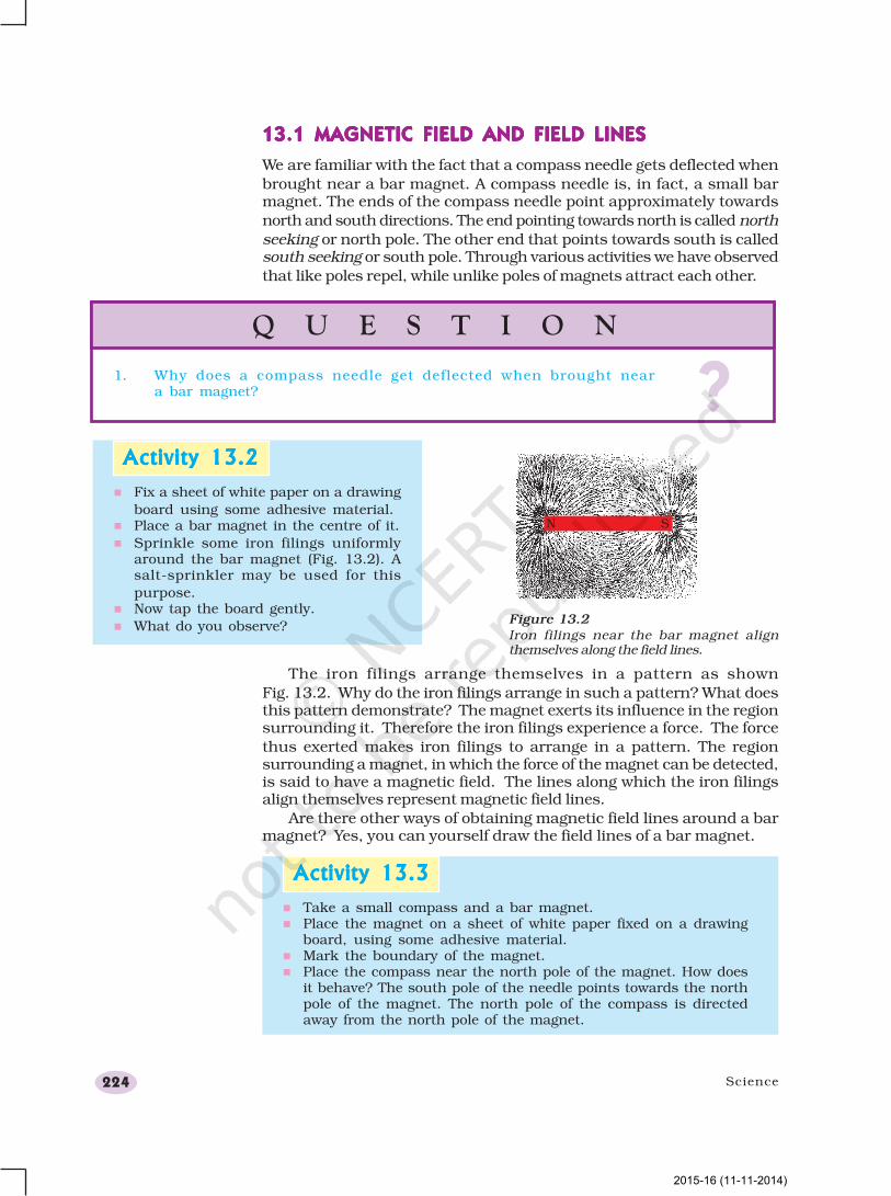
n Sprinkle some iron filings uniformlyaround the bar magnet (Fig. 13.2). Asalt-sprinkler may be used for this
purpose.n Now tap the board gently.
n What do you observe?Figure 13.2Iron filings near the bar magnet alignthemselves along the field lines.
The iron filings arrange themselves in a pattern as shown
Fig. 13.2. Why do the iron filings arrange in such a pattern? What doesthis pattern demonstrate? The magnet exerts its influence in the regionsurrounding it. Therefore the iron filings experience a force. The force
thus exerted makes iron filings to arrange in a pattern. The regionsurrounding a magnet, in which the force of the magnet can be detected,is said to have a magnetic field. The lines along which the iron filingsalign themselves represent magnetic field lines.
Are there other ways of obtaining magnetic field lines around a barmagnet? Yes, you can yourself draw the field lines of a bar magnet.
Activity 13.3Activity 13.3Activity 13.3Activity 13.3Activity 13.3
n Take a small compass and a bar magnet.n Place the magnet on a sheet of white paper fixed on a drawing
board, using some adhesive material.n Mark the boundary of the magnet.n Place the compass near the north pole of the magnet. How does
it behave? The south pole of the needle points towards the northpole of the magnet. The north pole of the compass is directedaway from the north pole of the magnet.
2015-16 (11-11-2014)
Magnetic Effects of Electric Current 225
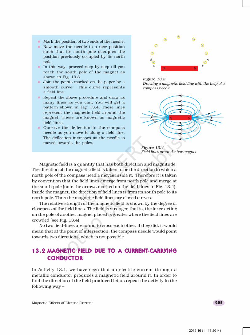
Magnetic field is a quantity that has both direction and magnitude.
The direction of the magnetic field is taken to be the direction in which a
north pole of the compass needle moves inside it. Therefore it is taken
by convention that the field lines emerge from north pole and merge at
the south pole (note the arrows marked on the field lines in Fig. 13.4).
Inside the magnet, the direction of field lines is from its south pole to its
north pole. Thus the magnetic field lines are closed curves.
The relative strength of the magnetic field is shown by the degree of
closeness of the field lines. The field is stronger, that is, the force acting
on the pole of another magnet placed is greater where the field lines are
crowded (see Fig. 13.4).
No two field-lines are found to cross each other. If they did, it would
mean that at the point of intersection, the compass needle would point
towards two directions, which is not possible.
13.213.213.213.213.2 MAMAMAMAMAGNETIC FIELD DUE TO A CURRENTGNETIC FIELD DUE TO A CURRENTGNETIC FIELD DUE TO A CURRENTGNETIC FIELD DUE TO A CURRENTGNETIC FIELD DUE TO A CURRENT-----CCCCCARRYINGARRYINGARRYINGARRYINGARRYING
CONDUCTORCONDUCTORCONDUCTORCONDUCTORCONDUCTOR
In Activity 13.1, we have seen that an electric current through a
metallic conductor produces a magnetic field around it. In order to
find the direction of the field produced let us repeat the activity in the
following way –
Figure 13.3Drawing a magnetic field line with the help of acompass needle
n Mark the position of two ends of the needle.
n Now move the needle to a new position
such that its south pole occupies the
position previously occupied by its north
pole.
n In this way, proceed step by step till you
reach the south pole of the magnet as
shown in Fig. 13.3.
n Join the points marked on the paper by a
smooth curve. This curve represents
a field line.
n Repeat the above procedure and draw as
many lines as you can. You will get a
pattern shown in Fig. 13.4. These lines
represent the magnetic field around the
magnet. These are known as magnetic
field lines.
n Observe the deflection in the compass
needle as you move it along a field line.
The deflection increases as the needle is
moved towards the poles.
Figure 13.4Field lines around a bar magnet
2015-16 (11-11-2014)
Science226
13.2.1 Magnetic Field due to a Current through a Straight
Conductor
What determines the pattern of the magnetic field generated by a currentthrough a conductor? Does the pattern depend on the shape of the
conductor? We shall investigate this with an activity.We shall first consider the pattern of the magnetic field around a
straight conductor carrying current.
Activity 13.4Activity 13.4Activity 13.4Activity 13.4Activity 13.4
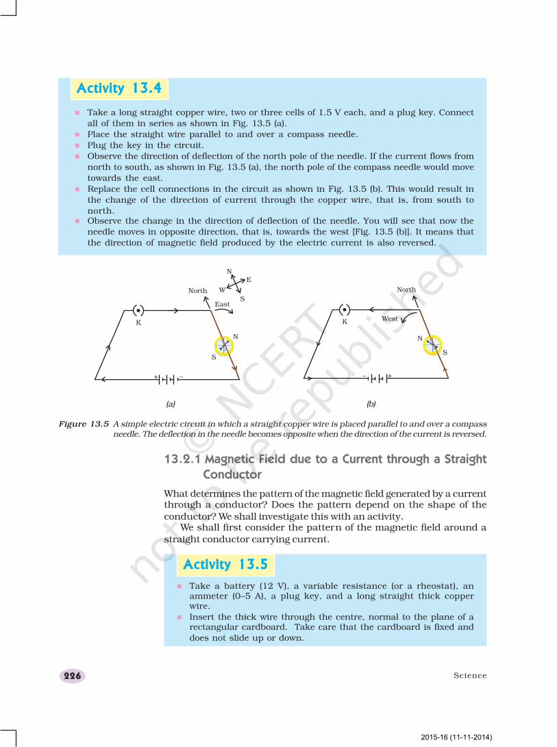
n Take a long straight copper wire, two or three cells of 1.5 V each, and a plug key. Connect
all of them in series as shown in Fig. 13.5 (a).
n Place the straight wire parallel to and over a compass needle.
n Plug the key in the circuit.
n Observe the direction of deflection of the north pole of the needle. If the current flows from
north to south, as shown in Fig. 13.5 (a), the north pole of the compass needle would move
towards the east.
n Replace the cell connections in the circuit as shown in Fig. 13.5 (b). This would result in
the change of the direction of current through the copper wire, that is, from south to
north.n Observe the change in the direction of deflection of the needle. You will see that now the
needle moves in opposite direction, that is, towards the west [Fig. 13.5 (b)]. It means that
the direction of magnetic field produced by the electric current is also reversed.
Figure 13.5 A simple electric circuit in which a straight copper wire is placed parallel to and over a compassneedle. The deflection in the needle becomes opposite when the direction of the current is reversed.
(a) (b)
Activity 13.5Activity 13.5Activity 13.5Activity 13.5Activity 13.5
n Take a battery (12 V), a variable resistance (or a rheostat), anammeter (0–5 A), a plug key, and a long straight thick copperwire.
n Insert the thick wire through the centre, normal to the plane of arectangular cardboard. Take care that the cardboard is fixed and
does not slide up or down.
2015-16 (11-11-2014)
Magnetic Effects of Electric Current 227
What happens to the deflection of the compass needle placed at a
given point if the current in the copper wire is changed? To see this, vary
the current in the wire. We find that the deflection in the needle alsochanges. In fact, if the current is increased, the deflection also increases.
It indicates that the magnitude of the magnetic field produced at a givenpoint increases as the current through the wire increases.
What happens to the deflection of the needle if the compass is moved
from the copper wire but the current through the wire remains the same?To see this, now place the compass at a farther point from the conducting
wire (say at point Q). What change do you observe? We see that thedeflection in the needle decreases. Thus the magnetic field produced by
a given current in the conductor decreases as the distance from it
increases. From Fig. 13.6, it can be noticed that the concentric circlesrepresenting the magnetic field around a current-carrying straight wire
become larger and larger as we move away from it.
13.2.2 Right-Hand Thumb Rule
A convenient way of finding the direction of magnetic field associated
with a current-carrying conductor is –
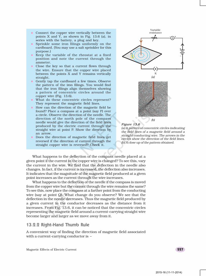
n Connect the copper wire vertically between thepoints X and Y, as shown in Fig. 13.6 (a), inseries with the battery, a plug and key.
n Sprinkle some iron filings uniformly on thecardboard. (You may use a salt sprinkler for thispurpose.)
n Keep the variable of the rheostat at a fixedposition and note the current through theammeter.
n Close the key so that a current flows through
the wire. Ensure that the copper wire placedbetween the points X and Y remains verticallystraight.
n Gently tap the cardboard a few times. Observethe pattern of the iron filings. You would findthat the iron filings align themselves showinga pattern of concentric circles around thecopper wire (Fig. 13.6).
n What do these concentric circles represent?They represent the magnetic field lines.
n How can the direction of the magnetic field befound? Place a compass at a point (say P) overa circle. Observe the direction of the needle. Thedirection of the north pole of the compassneedle would give the direction of the field linesproduced by the electric current through thestraight wire at point P. Show the direction byan arrow.
n Does the direction of magnetic field lines get
reversed if the direction of current through thestraight copper wire is reversed? Check it.
Figure 13.6(a) A pattern of concentric circles indicatingthe field lines of a magnetic field around astraight conducting wire. The arrows in thecircles show the direction of the field lines.(b) A close up of the pattern obtained.
(a)
(b)
Variableresistance
2015-16 (11-11-2014)
Science228
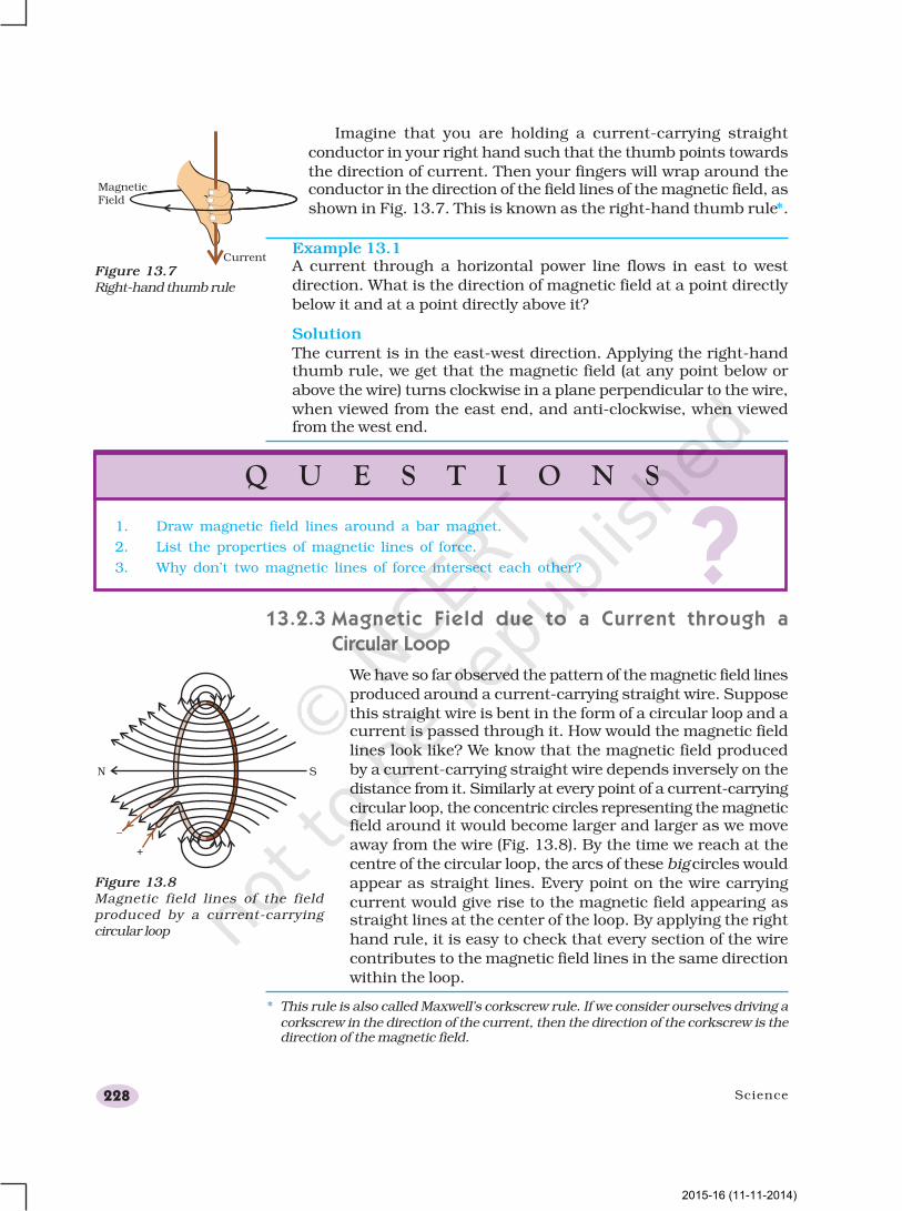
Imagine that you are holding a current-carrying straight
conductor in your right hand such that the thumb points towards
the direction of current. Then your fingers will wrap around theconductor in the direction of the field lines of the magnetic field, as
shown in Fig. 13.7. This is known as the right-hand thumb rule*.
Example 13.1A current through a horizontal power line flows in east to west
direction. What is the direction of magnetic field at a point directly
below it and at a point directly above it?
Solution
The current is in the east-west direction. Applying the right-handthumb rule, we get that the magnetic field (at any point below or
above the wire) turns clockwise in a plane perpendicular to the wire,
when viewed from the east end, and anti-clockwise, when viewedfrom the west end.
Figure 13.7Right-hand thumb rule
* This rule is also called Maxwell’s corkscrew rule. If we consider ourselves driving acorkscrew in the direction of the current, then the direction of the corkscrew is thedirection of the magnetic field.
13.2.3 Magnetic Field due to a Current through a
Circular Loop
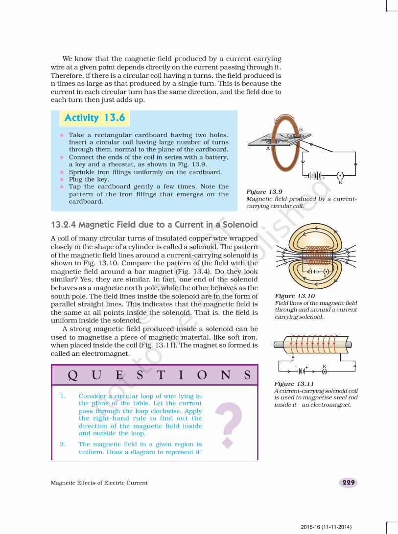
We have so far observed the pattern of the magnetic field lines
produced around a current-carrying straight wire. Suppose
this straight wire is bent in the form of a circular loop and acurrent is passed through it. How would the magnetic field
lines look like? We know that the magnetic field produced
by a current-carrying straight wire depends inversely on the
distance from it. Similarly at every point of a current-carrying
circular loop, the concentric circles representing the magneticfield around it would become larger and larger as we move
away from the wire (Fig. 13.8). By the time we reach at the
centre of the circular loop, the arcs of these big circles would
appear as straight lines. Every point on the wire carrying
current would give rise to the magnetic field appearing asstraight lines at the center of the loop. By applying the right
hand rule, it is easy to check that every section of the wire
contributes to the magnetic field lines in the same direction
within the loop.
Figure 13.8Magnetic field lines of the fieldproduced by a current-carryingcircular loop
?Q U E S T I O N S
1. Draw magnetic field lines around a bar magnet.
2. List the properties of magnetic lines of force.
3. Why don’t two magnetic lines of force intersect each other?
2015-16 (11-11-2014)
Magnetic Effects of Electric Current 229
We know that the magnetic field produced by a current-carrying
wire at a given point depends directly on the current passing through it.
Therefore, if there is a circular coil having n turns, the field produced isn times as large as that produced by a single turn. This is because the
current in each circular turn has the same direction, and the field due toeach turn then just adds up.
Activity 13.6Activity 13.6Activity 13.6Activity 13.6Activity 13.6
n Take a rectangular cardboard having two holes.Insert a circular coil having large number of turnsthrough them, normal to the plane of the cardboard.
n Connect the ends of the coil in series with a battery,a key and a rheostat, as shown in Fig. 13.9.
n Sprinkle iron filings uniformly on the cardboard.n Plug the key.n Tap the cardboard gently a few times. Note the
pattern of the iron filings that emerges on thecardboard.
Figure 13.9Magnetic field produced by a current-carrying circular coil.
13.2.4 Magnetic Field due to a Current in a Solenoid
A coil of many circular turns of insulated copper wire wrapped
closely in the shape of a cylinder is called a solenoid. The pattern
of the magnetic field lines around a current-carrying solenoid isshown in Fig. 13.10. Compare the pattern of the field with the
magnetic field around a bar magnet (Fig. 13.4). Do they looksimilar? Yes, they are similar. In fact, one end of the solenoid
behaves as a magnetic north pole, while the other behaves as the
south pole. The field lines inside the solenoid are in the form ofparallel straight lines. This indicates that the magnetic field is
the same at all points inside the solenoid. That is, the field isuniform inside the solenoid.
A strong magnetic field produced inside a solenoid can be
used to magnetise a piece of magnetic material, like soft iron,when placed inside the coil (Fig. 13.11). The magnet so formed is
called an electromagnet.
Figure 13.10Field lines of the magnetic fieldthrough and around a currentcarrying solenoid.
Figure 13.11A current-carrying solenoid coilis used to magnetise steel rodinside it – an electromagnet.
Q U E S T I O N S
?1. Consider a circular loop of wire lying in
the plane of the table. Let the current
pass through the loop clockwise. Applythe right-hand rule to find out the
direction of the magnetic field insideand outside the loop.
2. The magnetic field in a given region is
uniform. Draw a diagram to represent it.
2015-16 (11-11-2014)
Science230
13.313.313.313.313.3 FORCE ON A CURRENTFORCE ON A CURRENTFORCE ON A CURRENTFORCE ON A CURRENTFORCE ON A CURRENT-----CCCCCARRYING CONDUCTORARRYING CONDUCTORARRYING CONDUCTORARRYING CONDUCTORARRYING CONDUCTOR
IN A MAGNETIC FIELDIN A MAGNETIC FIELDIN A MAGNETIC FIELDIN A MAGNETIC FIELDIN A MAGNETIC FIELD
We have learnt that an electric current flowing through a conductorproduces a magnetic field. The field so produced exerts a force on a
magnet placed in the vicinity of the conductor. French scientist AndreMarie Ampere (1775–1836) suggested that the magnet must also exert
an equal and opposite force on the current-carrying conductor. The force
due to a magnetic field acting on a current-carrying conductor can bedemonstrated through the following activity.
3. Choose the correct option.
The magnetic field inside a long straight solenoid-carrying current
(a) is zero.
(b) decreases as we move towards its end.
(c) increases as we move towards its end.
(d) is the same at all points.
Activity 13.7Activity 13.7Activity 13.7Activity 13.7Activity 13.7
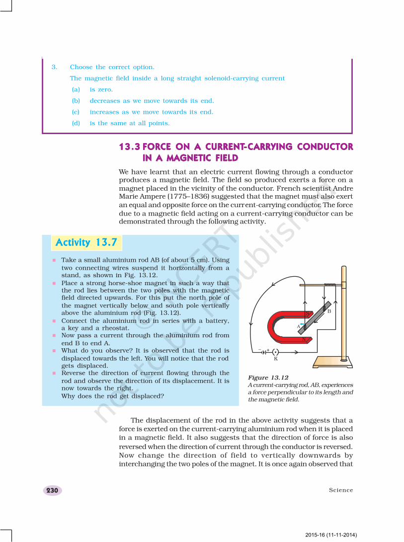
n Take a small aluminium rod AB (of about 5 cm). Using
two connecting wires suspend it horizontally from astand, as shown in Fig. 13.12.
n Place a strong horse-shoe magnet in such a way thatthe rod lies between the two poles with the magneticfield directed upwards. For this put the north pole of
the magnet vertically below and south pole verticallyabove the aluminium rod (Fig. 13.12).
n Connect the aluminium rod in series with a battery,a key and a rheostat.
n Now pass a current through the aluminium rod from
end B to end A.n What do you observe? It is observed that the rod is
displaced towards the left. You will notice that the rodgets displaced.
n Reverse the direction of current flowing through the
rod and observe the direction of its displacement. It isnow towards the right.
Why does the rod get displaced?
Figure 13.12A current-carrying rod, AB, experiencesa force perpendicular to its length andthe magnetic field.
The displacement of the rod in the above activity suggests that a
force is exerted on the current-carrying aluminium rod when it is placed
in a magnetic field. It also suggests that the direction of force is also
reversed when the direction of current through the conductor is reversed.
Now change the direction of field to vertically downwards by
interchanging the two poles of the magnet. It is once again observed that
2015-16 (11-11-2014)
Magnetic Effects of Electric Current 231
the direction of force acting on the current-carrying rod gets reversed. It
shows that the direction of the force on the conductor depends upon the
direction of current and the direction of the magnetic field. Experiments
have shown that the displacement of the rod is largest (or the magnitude
of the force is the highest) when the direction of current is at right angles
to the direction of the magnetic field. In such a condition we can use a
simple rule to find the direction of the force on the conductor.
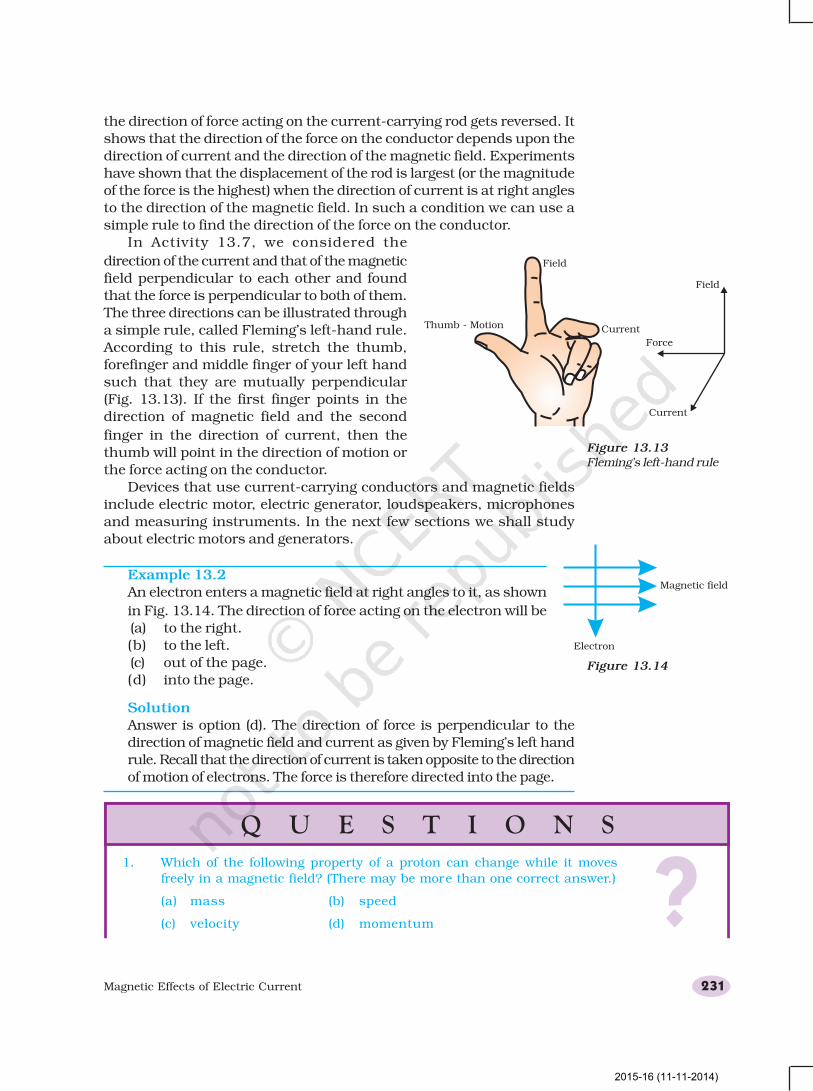
In Activity 13.7, we considered the
direction of the current and that of the magnetic
field perpendicular to each other and found
that the force is perpendicular to both of them.
The three directions can be illustrated through
a simple rule, called Fleming’s left-hand rule.
According to this rule, stretch the thumb,
forefinger and middle finger of your left hand
such that they are mutually perpendicular
(Fig. 13.13). If the first finger points in the
direction of magnetic field and the second
finger in the direction of current, then the
thumb will point in the direction of motion or
the force acting on the conductor.
Devices that use current-carrying conductors and magnetic fields
include electric motor, electric generator, loudspeakers, microphones
and measuring instruments. In the next few sections we shall study
about electric motors and generators.
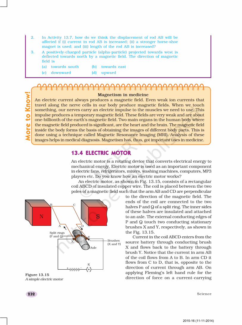
Example 13.2
An electron enters a magnetic field at right angles to it, as shown
in Fig. 13.14. The direction of force acting on the electron will be
(a) to the right.
(b) to the left.
(c) out of the page.
(d) into the page.
Solution
Answer is option (d). The direction of force is perpendicular to the
direction of magnetic field and current as given by Fleming’s left hand
rule. Recall that the direction of current is taken opposite to the direction
of motion of electrons. The force is therefore directed into the page.
Figure 13.13Fleming’s left-hand rule
Figure 13.14
Q U E S T I O N S
?1. Which of the following property of a proton can change while it moves
freely in a magnetic field? (There may be more than one correct answer.)
(a) mass (b) speed
(c) velocity (d) momentum
2015-16 (11-11-2014)
Science232
2. In Activity 13.7, how do we think the displacement of rod AB will beaffected if (i) current in rod AB is increased; (ii) a stronger horse-shoe
magnet is used; and (iii) length of the rod AB is increased?
3. A positively-charged particle (alpha-particle) projected towards west isdeflected towards north by a magnetic field. The direction of magnetic
field is
(a) towards south (b) towards east
(c) downward (d) upward
Magnetism in medicine
An electric current always produces a magnetic field. Even weak ion currents that
travel along the nerve cells in our body produce magnetic fields. When we touchsomething, our nerves carry an electric impulse to the muscles we need to use. This
impulse produces a temporary magnetic field. These fields are very weak and are aboutone-billionth of the earth’s magnetic field. Two main organs in the human body where
the magnetic field produced is significant, are the heart and the brain. The magnetic field
inside the body forms the basis of obtaining the images of different body parts. This isdone using a technique called Magnetic Resonance Imaging (MRI). Analysis of these
images helps in medical diagnosis. Magnetism has, thus, got important uses in medicine.
13.4 ELECTRIC MOTOR13.4 ELECTRIC MOTOR13.4 ELECTRIC MOTOR13.4 ELECTRIC MOTOR13.4 ELECTRIC MOTOR
An electric motor is a rotating device that converts electrical energy to
mechanical energy. Electric motor is used as an important componentin electric fans, refrigerators, mixers, washing machines, computers, MP3
players etc. Do you know how an electric motor works?
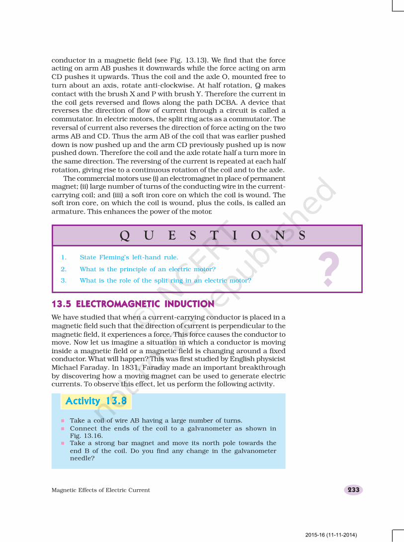
An electric motor, as shown in Fig. 13.15, consists of a rectangularcoil ABCD of insulated copper wire. The coil is placed between the two
poles of a magnetic field such that the arm AB and CD are perpendicular
to the direction of the magnetic field. The
ends of the coil are connected to the two
halves P and Q of a split ring. The inner sidesof these halves are insulated and attached
to an axle. The external conducting edges of
P and Q touch two conducting stationary
brushes X and Y, respectively, as shown in
the Fig. 13.15.Current in the coil ABCD enters from the
source battery through conducting brush
X and flows back to the battery through
brush Y. Notice that the current in arm AB
of the coil flows from A to B. In arm CD itflows from C to D, that is, opposite to the
direction of current through arm AB. On
applying Fleming’s left hand rule for the
direction of force on a current-carryingFigure 13.15
A simple electric motor
Mo
re t
o K
no
w!
N
2015-16 (11-11-2014)
Magnetic Effects of Electric Current 233
conductor in a magnetic field (see Fig. 13.13). We find that the forceacting on arm AB pushes it downwards while the force acting on arm
CD pushes it upwards. Thus the coil and the axle O, mounted free to
turn about an axis, rotate anti-clockwise. At half rotation, Q makes
contact with the brush X and P with brush Y. Therefore the current in
the coil gets reversed and flows along the path DCBA. A device thatreverses the direction of flow of current through a circuit is called a
commutator. In electric motors, the split ring acts as a commutator. The
reversal of current also reverses the direction of force acting on the two
arms AB and CD. Thus the arm AB of the coil that was earlier pushed
down is now pushed up and the arm CD previously pushed up is nowpushed down. Therefore the coil and the axle rotate half a turn more in
the same direction. The reversing of the current is repeated at each half
rotation, giving rise to a continuous rotation of the coil and to the axle.
The commercial motors use (i) an electromagnet in place of permanentmagnet; (ii) large number of turns of the conducting wire in the current-
carrying coil; and (iii) a soft iron core on which the coil is wound. Thesoft iron core, on which the coil is wound, plus the coils, is called an
armature. This enhances the power of the motor.
Activity 13.8Activity 13.8Activity 13.8Activity 13.8Activity 13.8
Q U E S T I O N S
?1. State Fleming’s left-hand rule.
2. What is the principle of an electric motor?
3. What is the role of the split ring in an electric motor?
13.5 ELECTROMAGNETIC INDUCTION13.5 ELECTROMAGNETIC INDUCTION13.5 ELECTROMAGNETIC INDUCTION13.5 ELECTROMAGNETIC INDUCTION13.5 ELECTROMAGNETIC INDUCTION
We have studied that when a current-carrying conductor is placed in a
magnetic field such that the direction of current is perpendicular to the
magnetic field, it experiences a force. This force causes the conductor tomove. Now let us imagine a situation in which a conductor is moving
inside a magnetic field or a magnetic field is changing around a fixedconductor. What will happen? This was first studied by English physicist
Michael Faraday. In 1831, Faraday made an important breakthrough
by discovering how a moving magnet can be used to generate electriccurrents. To observe this effect, let us perform the following activity.
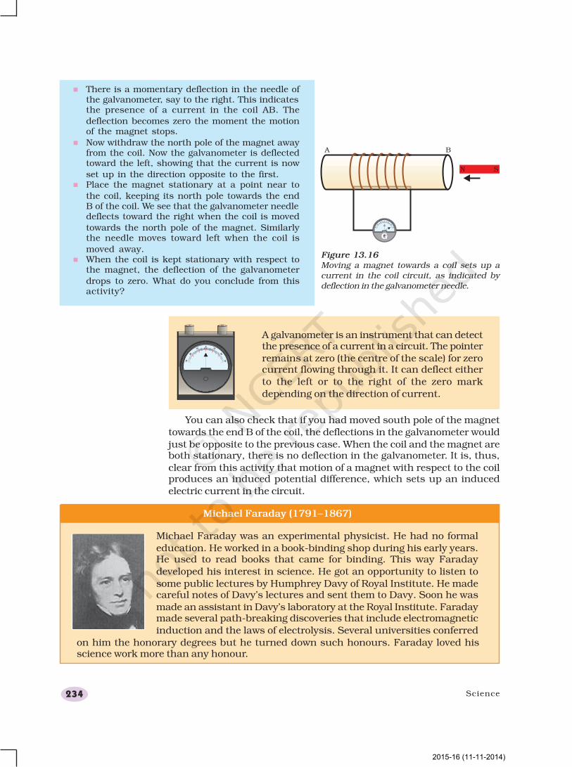
n Take a coil of wire AB having a large number of turns.
n Connect the ends of the coil to a galvanometer as shown inFig. 13.16.
n Take a strong bar magnet and move its north pole towards the
end B of the coil. Do you find any change in the galvanometerneedle?
2015-16 (11-11-2014)
Science234
n There is a momentary deflection in the needle ofthe galvanometer, say to the right. This indicatesthe presence of a current in the coil AB. The
deflection becomes zero the moment the motionof the magnet stops.
n Now withdraw the north pole of the magnet awayfrom the coil. Now the galvanometer is deflectedtoward the left, showing that the current is now
set up in the direction opposite to the first.n Place the magnet stationary at a point near to
the coil, keeping its north pole towards the endB of the coil. We see that the galvanometer needledeflects toward the right when the coil is moved
towards the north pole of the magnet. Similarlythe needle moves toward left when the coil is
moved away.n When the coil is kept stationary with respect to
the magnet, the deflection of the galvanometer
drops to zero. What do you conclude from thisactivity?
Figure 13.16Moving a magnet towards a coil sets up acurrent in the coil circuit, as indicated bydeflection in the galvanometer needle.
A galvanometer is an instrument that can detectthe presence of a current in a circuit. The pointer
remains at zero (the centre of the scale) for zerocurrent flowing through it. It can deflect either
to the left or to the right of the zero mark
depending on the direction of current.
You can also check that if you had moved south pole of the magnet
towards the end B of the coil, the deflections in the galvanometer would
just be opposite to the previous case. When the coil and the magnet areboth stationary, there is no deflection in the galvanometer. It is, thus,
clear from this activity that motion of a magnet with respect to the coilproduces an induced potential difference, which sets up an induced
electric current in the circuit.
Michael Faraday (1791–1867)
Michael Faraday was an experimental physicist. He had no formal
education. He worked in a book-binding shop during his early years.He used to read books that came for binding. This way Faraday
developed his interest in science. He got an opportunity to listen to
some public lectures by Humphrey Davy of Royal Institute. He madecareful notes of Davy’s lectures and sent them to Davy. Soon he was
made an assistant in Davy’s laboratory at the Royal Institute. Faradaymade several path-breaking discoveries that include electromagnetic
induction and the laws of electrolysis. Several universities conferred
on him the honorary degrees but he turned down such honours. Faraday loved hisscience work more than any honour.
2015-16 (11-11-2014)

Magnetic Effects of Electric Current 235
Let us now perform a variation of Activity 13.8 in which the moving
magnet is replaced by a current-carrying coil and the current in the coil
can be varied.
Activity 13.9Activity 13.9Activity 13.9Activity 13.9Activity 13.9
n Take two different coils of copper wire havinglarge number of turns (say 50 and 100 turns
respectively). Insert them over a non-conductingcylindrical roll, as shown in Fig. 13.17. (You mayuse a thick paper roll for this purpose.)
n Connect the coil-1, having larger number ofturns, in series with a battery and a plug key.
Also connect the other coil-2 with agalvanometer as shown.
n Plug in the key. Observe the galvanometer. Is
there a deflection in its needle? You will observethat the needle of the galvanometer instantly
jumps to one side and just as quickly returns tozero, indicating a momentary current in coil-2.
n Disconnect coil-1 from the battery. You will
observe that the needle momentarily moves, butto the opposite side. It means that now the
current flows in the opposite direction in coil-2.
Figure 13.17Current is induced in coil-2 when currentin coil-1 is changed
In this activity we observe that as soon as the current in coil-1 reacheseither a steady value or zero, the galvanometer in coil-2 shows nodeflection.
From these observations, we conclude that a potential difference is
induced in the coil-2 whenever the electric current through the coil–1is changing (starting or stopping). Coil-1 is called the primary coil andcoil-2 is called the secondary coil. As the current in the first coil changes,the magnetic field associated with it also changes. Thus the magneticfield lines around the secondary coil also change. Hence the change in
magnetic field lines associated with the secondary coil is the cause ofinduced electric current in it. This process, by which a changingmagnetic field in a conductor induces a current in another conductor,is called electromagnetic induction. In practice we can induce currentin a coil either by moving it in a magnetic field or by changing the
magnetic field around it. It is convenient in most situations to movethe coil in a magnetic field.
The induced current is found to be the highest whenthe direction of motion of the coil is at right angles to themagnetic field. In this situation, we can use a simple rule
to know the direction of the induced current. Stretch thethumb, forefinger and middle finger of right hand so thatthey are perpendicular to each other, as shown inFig. 13.18. If the forefinger indicates the direction of themagnetic field and the thumb shows the direction of motion
of conductor, then the middle finger will show the directionof induced current. This simple rule is called Fleming’sright-hand rule.
Figure 13.18Fleming’s right-hand rule
2015-16 (11-11-2014)
Science236
13.6 ELECTRIC GENER13.6 ELECTRIC GENER13.6 ELECTRIC GENER13.6 ELECTRIC GENER13.6 ELECTRIC GENERAAAAATORTORTORTORTOR
Based on the phenomenon of electromagnetic induction, the experimentsstudied above generate induced current, which is usually very small.
This principle is also employed to produce large currents for use in homes
and industry. In an electric generator, mechanical energy is used to rotatea conductor in a magnetic field to produce electricity.
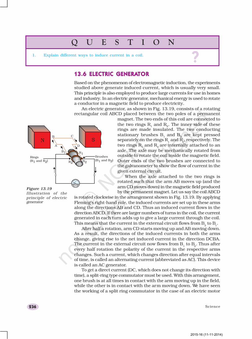
An electric generator, as shown in Fig. 13.19, consists of a rotatingrectangular coil ABCD placed between the two poles of a permanent
magnet. The two ends of this coil are connected to
the two rings R1 and R
2. The inner side of these
rings are made insulated. The two conducting
stationary brushes B1 and B
2 are kept pressed
separately on the rings R1 and R
2, respectively. The
two rings R1 and R
2 are internally attached to an
axle. The axle may be mechanically rotated fromoutside to rotate the coil inside the magnetic field.
Outer ends of the two brushes are connected tothe galvanometer to show the flow of current in the
given external circuit.
When the axle attached to the two rings isrotated such that the arm AB moves up (and the
arm CD moves down) in the magnetic field producedby the permanent magnet. Let us say the coil ABCD
is rotated clockwise in the arrangement shown in Fig. 13.19. By applying
Fleming’s right-hand rule, the induced currents are set up in these armsalong the directions AB and CD. Thus an induced current flows in the
direction ABCD. If there are larger numbers of turns in the coil, the currentgenerated in each turn adds up to give a large current through the coil.
This means that the current in the external circuit flows from B2 to B
1.
After half a rotation, arm CD starts moving up and AB moving down.As a result, the directions of the induced currents in both the arms
change, giving rise to the net induced current in the direction DCBA.The current in the external circuit now flows from B
1 to B
2. Thus after
every half rotation the polarity of the current in the respective arms
changes. Such a current, which changes direction after equal intervalsof time, is called an alternating current (abbreviated as AC). This device
is called an AC generator.To get a direct current (DC, which does not change its direction with
time), a split-ring type commutator must be used. With this arrangement,
one brush is at all times in contact with the arm moving up in the field,while the other is in contact with the arm moving down. We have seen
the working of a split ring commutator in the case of an electric motor
Q U E S T I O N
?1. Explain different ways to induce current in a coil.
Figure 13.19Illustration of theprinciple of electricgenerator
2015-16 (11-11-2014)
Magnetic Effects of Electric Current 237
(see Fig. 13.15). Thus a unidirectional current is produced. The generator
is thus called a DC generator.
The difference between the direct and alternating currents is that thedirect current always flows in one direction, whereas the alternating
current reverses its direction periodically. Most power stationsconstructed these days produce AC. In India, the AC changes direction
after every 1/100 second, that is, the frequency of AC is 50 Hz. An
important advantage of AC over DC is that electric power can betransmitted over long distances without much loss of energy.
Q U E S T I O N S
?1. State the principle of an electric generator.
2. Name some sources of direct current.
3. Which sources produce alternating current?
4. Choose the correct option.
A rectangular coil of copper wires is rotated in a magnetic field. Thedirection of the induced current changes once in each
(a) two revolutions (b) one revolution
(c) half revolution (d) one-fourth revolution
13.7 DOMESTIC ELECTRIC CIRCUITS13.7 DOMESTIC ELECTRIC CIRCUITS13.7 DOMESTIC ELECTRIC CIRCUITS13.7 DOMESTIC ELECTRIC CIRCUITS13.7 DOMESTIC ELECTRIC CIRCUITS
In our homes, we receive supply of electric power through a main supply
(also called mains), either supported through overhead electric poles or
by underground cables. One of the wires in this supply, usually with
red insulation cover, is called live wire (or positive). Another wire, with
black insulation, is called neutral wire (or negative). In our country, the
potential difference between the two is 220 V.
At the metre-board in the house, these wires pass into an electricity
meter through a main fuse. Through the main switch they are connected
to the line wires in the house. These wires supply electricity to separate
circuits within the house. Often, two separate circuits are used, one of
15 A current rating for appliances with higher power ratings such as
geysers, air coolers, etc. The other circuit is of 5 A current rating for
bulbs, fans, etc. The earth wire, which has insulation of green colour, is
usually connected to a metal plate deep in the earth near the house.
This is used as a safety measure, especially for those appliances that
have a metallic body, for example, electric press, toaster, table fan,
refrigerator, etc. The metallic body is connected to the earth wire, which
provides a low-resistance conducting path for the current. Thus, it
ensures that any leakage of current to the metallic body of the appliance
keeps its potential to that of the earth, and the user may not get a severe
electric shock.
2015-16 (11-11-2014)
Science238
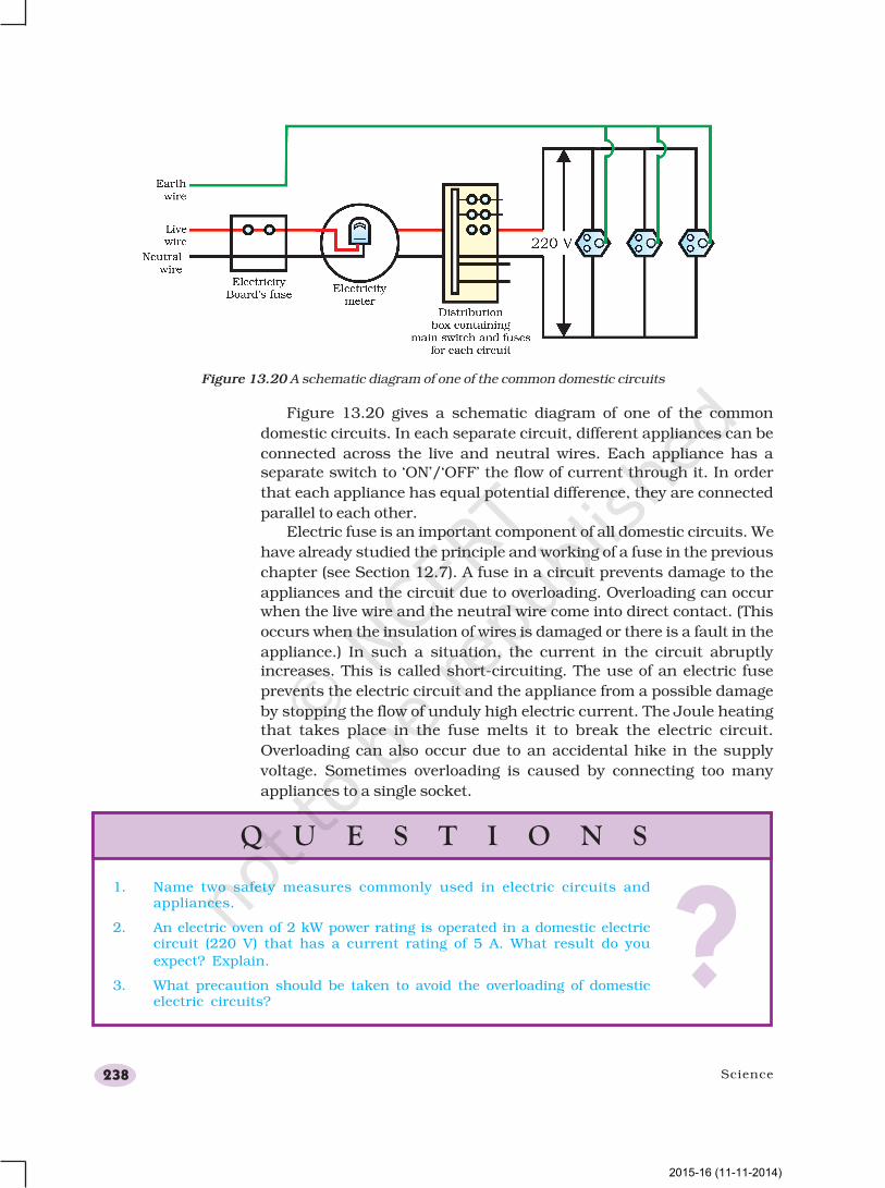
Figure 13.20 gives a schematic diagram of one of the common
domestic circuits. In each separate circuit, different appliances can be
connected across the live and neutral wires. Each appliance has a
separate switch to ‘ON’/‘OFF’ the flow of current through it. In order
that each appliance has equal potential difference, they are connected
parallel to each other.
Electric fuse is an important component of all domestic circuits. We
have already studied the principle and working of a fuse in the previous
chapter (see Section 12.7). A fuse in a circuit prevents damage to the
appliances and the circuit due to overloading. Overloading can occur
when the live wire and the neutral wire come into direct contact. (This
occurs when the insulation of wires is damaged or there is a fault in the
appliance.) In such a situation, the current in the circuit abruptly
increases. This is called short-circuiting. The use of an electric fuse
prevents the electric circuit and the appliance from a possible damage
by stopping the flow of unduly high electric current. The Joule heating
that takes place in the fuse melts it to break the electric circuit.
Overloading can also occur due to an accidental hike in the supply
voltage. Sometimes overloading is caused by connecting too many
appliances to a single socket.
Figure 13.20 A schematic diagram of one of the common domestic circuits
Q U E S T I O N S
?1. Name two safety measures commonly used in electric circuits and
appliances.
2. An electric oven of 2 kW power rating is operated in a domestic electriccircuit (220 V) that has a current rating of 5 A. What result do you
expect? Explain.
3. What precaution should be taken to avoid the overloading of domesticelectric circuits?
2015-16 (11-11-2014)
Magnetic Effects of Electric Current 239
What you have learnt
n A compass needle is a small magnet. Its one end, which points towards north, is
called a north pole, and the other end, which points towards south, is called a
south pole.
n A magnetic field exists in the region surrounding a magnet, in which the force of
the magnet can be detected.
n Field lines are used to represent a magnetic field. A field line is the path along
which a hypothetical free north pole would tend to move. The direction of the
magnetic field at a point is given by the direction that a north pole placed at that
point would take. Field lines are shown closer together where the magnetic field is
greater.
n A metallic wire carrying an electric current has associated with it a magnetic field.
The field lines about the wire consist of a series of concentric circles whose direction
is given by the right-hand rule.
n The pattern of the magnetic field around a conductor due to an electric current
flowing through it depends on the shape of the conductor. The magnetic field of a
solenoid carrying a current is similar to that of a bar magnet.
n An electromagnet consists of a core of soft iron wrapped around with a coil of
insulated copper wire.
n A current-carrying conductor when placed in a magnetic field experiences a force.
If the direction of the field and that of the current are mutually perpendicular to
each other, then the force acting on the conductor will be perpendicular to both
and will be given by Fleming’s left-hand rule. This is the basis of an electric motor.
An electric motor is a device that converts electric energy into mechanical energy.
n The phenomenon of electromagnetic induction is the production of induced current
in a coil placed in a region where the magnetic field changes with time. The magnetic
field may change due to a relative motion between the coil and a magnet placed
near to the coil. If the coil is placed near to a current-carrying conductor, the
magnetic field may change either due to a change in the current through the
conductor or due to the relative motion between the coil and conductor. The
direction of the induced current is given by the Fleming’s right-hand rule.
n A generator converts mechanical energy into electrical energy. It works on the basis
of electromagnetic induction.
n In our houses we receive AC electric power of 220 V with a frequency of 50 Hz. One
of the wires in this supply is with red insulation, called live wire. The other one is of
black insulation, which is a neutral wire. The potential difference between the two
is 220 V. The third is the earth wire that has green insulation and this is connected
to a metallic body deep inside earth. It is used as a safety measure to ensure that
any leakage of current to a metallic body does not give any severe shock to a user.
n Fuse is the most important safety device, used for protecting the circuits due to
short-circuiting or overloading of the circuits.
2015-16 (11-11-2014)
Science240
E X E R C I S E S
1. Which of the following correctly describes the magnetic field near a long
straight wire?
(a) The field consists of straight lines perpendicular to the wire.
(b) The field consists of straight lines parallel to the wire.
(c) The field consists of radial lines originating from the wire.
(d) The field consists of concentric circles centred on the wire.
2. The phenomenon of electromagnetic induction is
(a) the process of charging a body.
(b) the process of generating magnetic field due to a current passing
through a coil.
(c) producing induced current in a coil due to relative motion between a
magnet and the coil.
(d) the process of rotating a coil of an electric motor.
3. The device used for producing electric current is called a
(a) generator.
(b) galvanometer.
(c) ammeter.
(d) motor.
4. The essential difference between an AC generator and a DC generator is that
(a) AC generator has an electromagnet while a DC generator has
permanent magnet.
(b) DC generator will generate a higher voltage.
(c) AC generator will generate a higher voltage.
(d) AC generator has slip rings while the DC generator has a commutator.
5. At the time of short circuit, the current in the circuit
(a) reduces substantially.
(b) does not change.
(c) increases heavily.
(d) vary continuously.
6. State whether the following statements are true or false.
(a) An electric motor converts mechanical energy into electrical energy.
(b) An electric generator works on the principle of electromagnetic induction.
(c) The field at the centre of a long circular coil carrying current will be
parallel straight lines.
(d) A wire with a green insulation is usually the live wire of an electric supply.
7. List two methods of producing magnetic fields.
2015-16 (11-11-2014)
Magnetic Effects of Electric Current 241
8. How does a solenoid behave like a magnet? Can you determine the north and
south poles of a current–carrying solenoid with the help of a bar magnet? Explain.
9. When is the force experienced by a current–carrying conductor placed in a magneticfield largest?
10. Imagine that you are sitting in a chamber with your back to one wall. An electronbeam, moving horizontally from back wall towards the front wall, is deflected by a
strong magnetic field to your right side. What is the direction of magnetic field?
11. Draw a labelled diagram of an electric motor. Explain its principle and working.What is the function of a split ring in an electric motor?
12. Name some devices in which electric motors are used.
13. A coil of insulated copper wire is connected to a galvanometer. What will happen if
a bar magnet is (i) pushed into the coil, (ii) withdrawn from inside the coil, (iii) held
stationary inside the coil?
14. Two circular coils A and B are placed closed to each other. If the current in the coil
A is changed, will some current be induced in the coil B? Give reason.
15. State the rule to determine the direction of a (i) magnetic field produced around a
straight conductor-carrying current, (ii) force experienced by a current-carrying
straight conductor placed in a magnetic field which is perpendicular to it, and(iii) current induced in a coil due to its rotation in a magnetic field.
16. Explain the underlying principle and working of an electric generator by drawinga labelled diagram. What is the function of brushes?
17. When does an electric short circuit occur?
18. What is the function of an earth wire? Why is it necessary to earth metallicappliances?
2015-16 (11-11-2014)
Recommended