Chain Breaker, Press and Riveting Tool P/N 08-0467
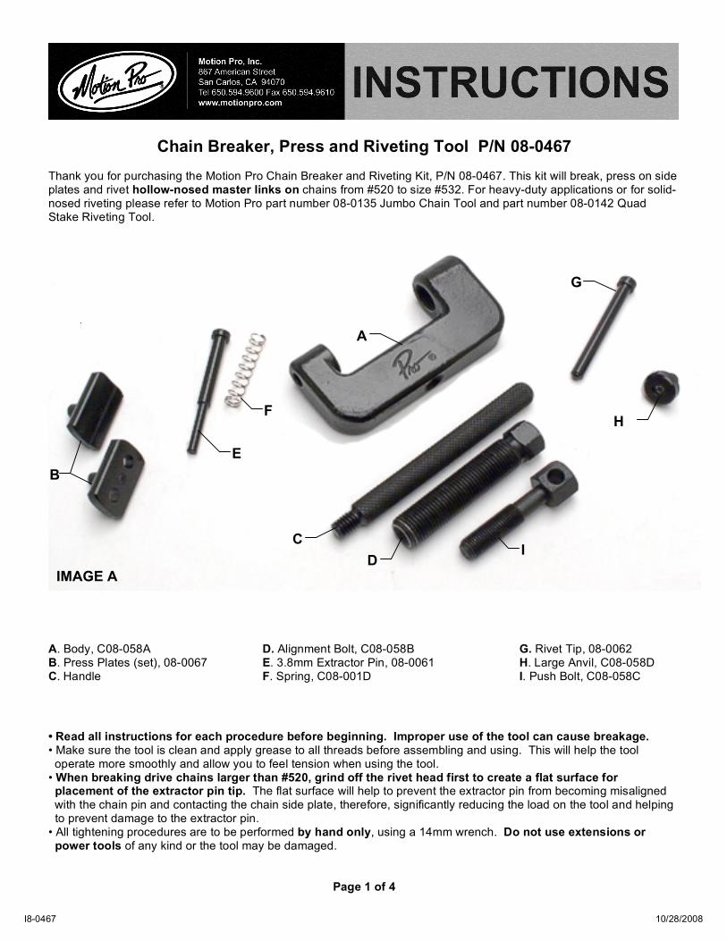
Thank you for purchasing the Motion Pro Chain Breaker and Riveting Kit, P/N 08-0467. This kit will break, press on side plates and rivet hollow-nosed master links on chains from #520 to size #532. For heavy-duty applications or for solid-nosed riveting please refer to Motion Pro part number 08-0135 Jumbo Chain Tool and part number 08-0142 Quad Stake Riveting Tool. IMAGE A A. Body, C08-058A D. Alignment Bolt, C08-058B G. Rivet Tip, 08-0062 B. Press Plates (set), 08-0067 E. 3.8mm Extractor Pin, 08-0061 H. Large Anvil, C08-058D C. Handle F. Spring, C08-001D I. Push Bolt, C08-058C • Read all instructions for each procedure before beginning. Improper use of the tool can cause breakage. • Make sure the tool is clean and apply grease to all threads before assembling and using. This will help the tool operate more smoothly and allow you to feel tension when using the tool. • When breaking drive chains larger than #520, grind off the rivet head first to create a flat surface for placement of the extractor pin tip. The flat surface will help to prevent the extractor pin from becoming misaligned with the chain pin and contacting the chain side plate, therefore, significantly reducing the load on the tool and helping to prevent damage to the extractor pin. • All tightening procedures are to be performed by hand only, using a 14mm wrench. Do not use extensions or power tools of any kind or the tool may be damaged.
Page 1 of 4
10/28/2008
A
I C
F
E
G
H
B
D
I8-0467
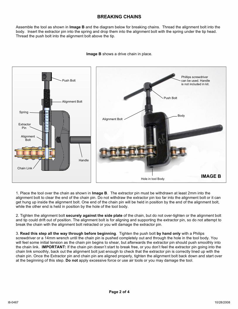
BREAKING CHAINS
Assemble the tool as shown in Image B and the diagram below for breaking chains. Thread the alignment bolt into the body. Insert the extractor pin into the spring and drop them into the alignment bolt with the spring under the tip head. Thread the push bolt into the alignment bolt above the tip.
Image B shows a drive chain in place.
1. Place the tool over the chain as shown in Image B. The extractor pin must be withdrawn at least 2mm into the alignment bolt to clear the end of the chain pin. Do not withdraw the extractor pin too far into the alignment bolt or it can get hung up inside the alignment bolt. One end of the chain pin will be held in position by the end of the alignment bolt, while the other end is held in position by the hole of the tool body. 2. Tighten the alignment bolt securely against the side plate of the chain, but do not over-tighten or the alignment bolt and tip could drift out of position. The alignment bolt is for aligning and supporting the extractor pin, so do not attempt to break the chain with the alignment bolt retracted or you will damage the extractor pin. 3. Read this step all the way through before beginning. Tighten the push bolt by hand only with a Philips screwdriver or a 14mm wrench until the chain pin is pushed completely out and through the hole in the tool body. You will feel some initial tension as the chain pin begins to shear, but afterwards the extractor pin should push smoothly into the chain link. IMPORTANT: If the chain pin doesn’t start to break free, or you don’t feel the extractor pin going into the chain link smoothly, back out the alignment bolt just enough to check that the extractor pin is correctly lined up with the chain pin. Once the Extractor pin and chain pin are aligned properly, tighten the alignment bolt back down and start over at the beginning of this step. Do not apply excessive force or use air tools or you may damage the tool.
Page 2 of 4
Push Bolt
Alignment Bolt
Spring Extractor Pin Alignment Bolt
Handle
Chain Link
Body
Hole in tool Body
Push Bolt
Alignment Bolt
IMAGE B
10/28/2008 I8-0467
Phillips screwdriver can be used. Handle is not included in kit.
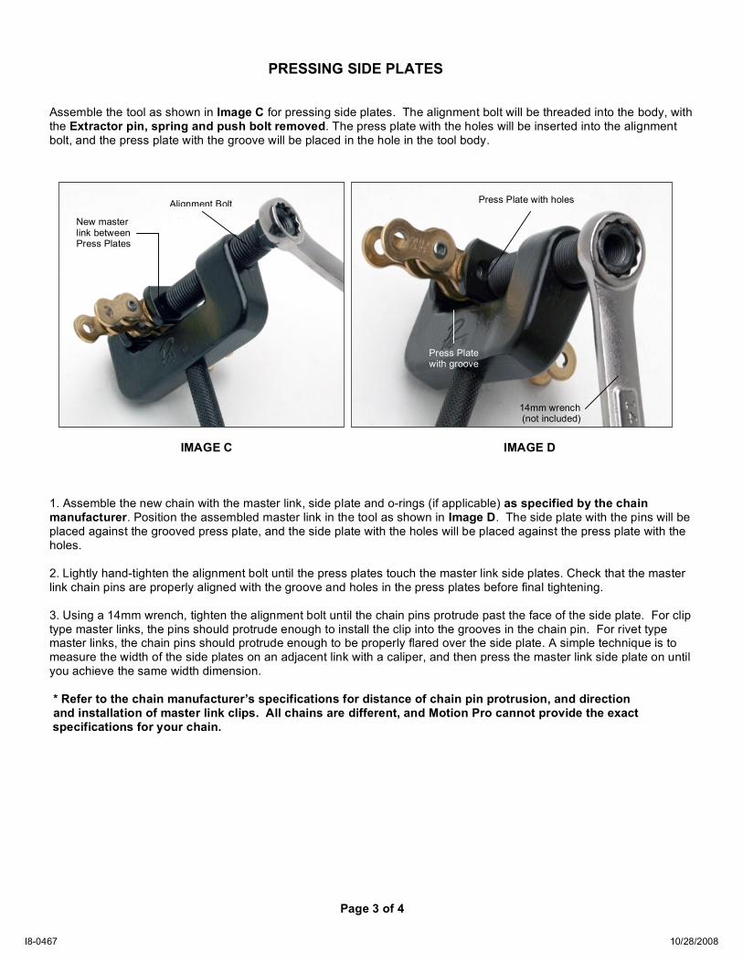
PRESSING SIDE PLATES
Assemble the tool as shown in Image C for pressing side plates. The alignment bolt will be threaded into the body, with the Extractor pin, spring and push bolt removed. The press plate with the holes will be inserted into the alignment bolt, and the press plate with the groove will be placed in the hole in the tool body.
IMAGE C IMAGE D 1. Assemble the new chain with the master link, side plate and o-rings (if applicable) as specified by the chain manufacturer. Position the assembled master link in the tool as shown in Image D. The side plate with the pins will be placed against the grooved press plate, and the side plate with the holes will be placed against the press plate with the holes. 2. Lightly hand-tighten the alignment bolt until the press plates touch the master link side plates. Check that the master link chain pins are properly aligned with the groove and holes in the press plates before final tightening. 3. Using a 14mm wrench, tighten the alignment bolt until the chain pins protrude past the face of the side plate. For clip type master links, the pins should protrude enough to install the clip into the grooves in the chain pin. For rivet type master links, the chain pins should protrude enough to be properly flared over the side plate. A simple technique is to measure the width of the side plates on an adjacent link with a caliper, and then press the master link side plate on until you achieve the same width dimension. * Refer to the chain manufacturer’s specifications for distance of chain pin protrusion, and direction and installation of master link clips. All chains are different, and Motion Pro cannot provide the exact
specifications for your chain.
Page 3 of 4
Press Plate with holes
Press Plate with groove
Alignment Bolt
14mm wrench (not included)
New master link between Press Plates
10/28/2008 I8-0467
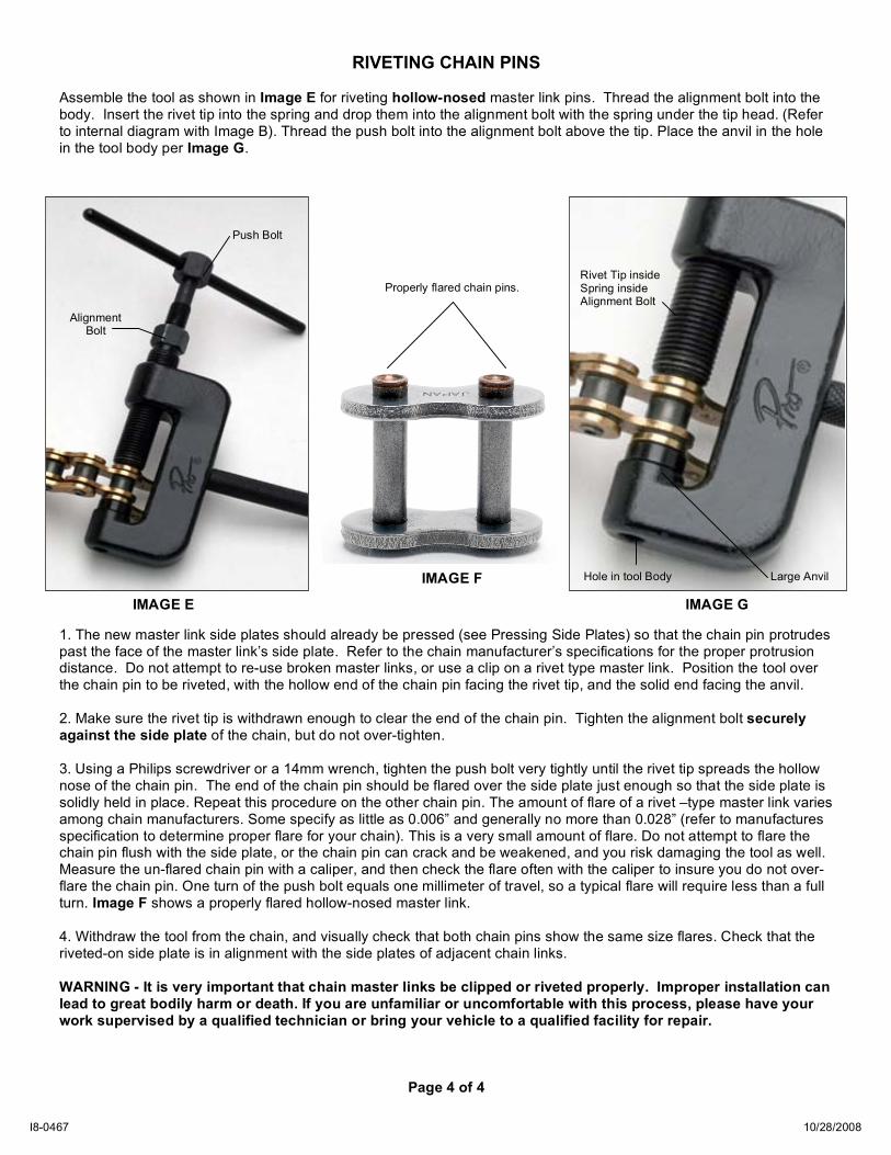
RIVETING CHAIN PINS
Assemble the tool as shown in Image E for riveting hollow-nosed master link pins. Thread the alignment bolt into the body. Insert the rivet tip into the spring and drop them into the alignment bolt with the spring under the tip head. (Refer to internal diagram with Image B). Thread the push bolt into the alignment bolt above the tip. Place the anvil in the hole in the tool body per Image G. 1. The new master link side plates should already be pressed (see Pressing Side Plates) so that the chain pin protrudes past the face of the master link’s side plate. Refer to the chain manufacturer’s specifications for the proper protrusion distance. Do not attempt to re-use broken master links, or use a clip on a rivet type master link. Position the tool over the chain pin to be riveted, with the hollow end of the chain pin facing the rivet tip, and the solid end facing the anvil. 2. Make sure the rivet tip is withdrawn enough to clear the end of the chain pin. Tighten the alignment bolt securely against the side plate of the chain, but do not over-tighten. 3. Using a Philips screwdriver or a 14mm wrench, tighten the push bolt very tightly until the rivet tip spreads the hollow nose of the chain pin. The end of the chain pin should be flared over the side plate just enough so that the side plate is solidly held in place. Repeat this procedure on the other chain pin. The amount of flare of a rivet –type master link varies among chain manufacturers. Some specify as little as 0.006” and generally no more than 0.028” (refer to manufactures specification to determine proper flare for your chain). This is a very small amount of flare. Do not attempt to flare the chain pin flush with the side plate, or the chain pin can crack and be weakened, and you risk damaging the tool as well. Measure the un-flared chain pin with a caliper, and then check the flare often with the caliper to insure you do not over-flare the chain pin. One turn of the push bolt equals one millimeter of travel, so a typical flare will require less than a full turn. Image F shows a properly flared hollow-nosed master link. 4. Withdraw the tool from the chain, and visually check that both chain pins show the same size flares. Check that the riveted-on side plate is in alignment with the side plates of adjacent chain links. WARNING - It is very important that chain master links be clipped or riveted properly. Improper installation can lead to great bodily harm or death. If you are unfamiliar or uncomfortable with this process, please have your work supervised by a qualified technician or bring your vehicle to a qualified facility for repair.
Page 4 of 4
Push Bolt
Alignment Bolt
Rivet Tip inside Spring inside Alignment Bolt
Hole in tool Body
Properly flared chain pins.
IMAGE E IMAGE F
IMAGE G
Large Anvil
10/28/2008 I8-0467
Recommended