Building Hints and Suggestions
For Your
Victor Soling 1 Meter
By
Curtis Wright
for the
Stowe Yacht Club
Written 1988 Revised June 1998
Edited and updated May 2003 by Paul and Diane Fixx
Building Hints and Suggestions For Your Victor Soling 1 Meter
Page 2
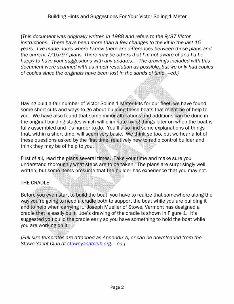
{This document was originally written in 1988 and refers to the 9/87 Victor instructions. There have been more than a few changes to the kit in the last 15 years. I’ve made notes where I know there are differences between those plans and the current 7/15/97 plans. There may be others that I’m not aware of and I’d be happy to have your suggestions with any updates.. The drawings included with this document were scanned with as much resolution as possible, but we only had copies of copies since the originals have been lost in the sands of time. –ed.} Having built a fair number of Victor Soling 1 Meter kits for our fleet, we have found some short cuts and ways to go about building these boats that might be of help to you. We have also found that some minor alterations and additions can be done in the original building stages which will eliminate fixing things later on when the boat is fully assembled and it’s harder to do. You’ll also find some explanations of things that, within a short time, will seem very basic. We think so too, but we hear a lot of these questions asked by the first time, relatively new to radio control builder and think they may be of help to you. First of all, read the plans several times. Take your time and make sure you understand thoroughly what steps are to be taken. The plans are surprisingly well written, but some items presume that the builder has experience that you may not. THE CRADLE Before you even start to build the boat, you have to realize that somewhere along the way you’re going to need a cradle both to support the boat while you are building it and to help when carrying it. Joseph Mueller of Stowe, Vermont has designed a cradle that is easily built. Joe’s drawing of the cradle is shown in Figure 1. It’s suggested you build the cradle early so you have something to hold the boat while you are working on it {Full size templates are attached as Appendix A, or can be downloaded from the Stowe Yacht Club at stoweyachtclub.org. –ed.}
Building Hints and Suggestions For Your Victor Soling 1 Meter
Page 3
.
Figure 1 - Cradle
Building Hints and Suggestions For Your Victor Soling 1 Meter
Page 4
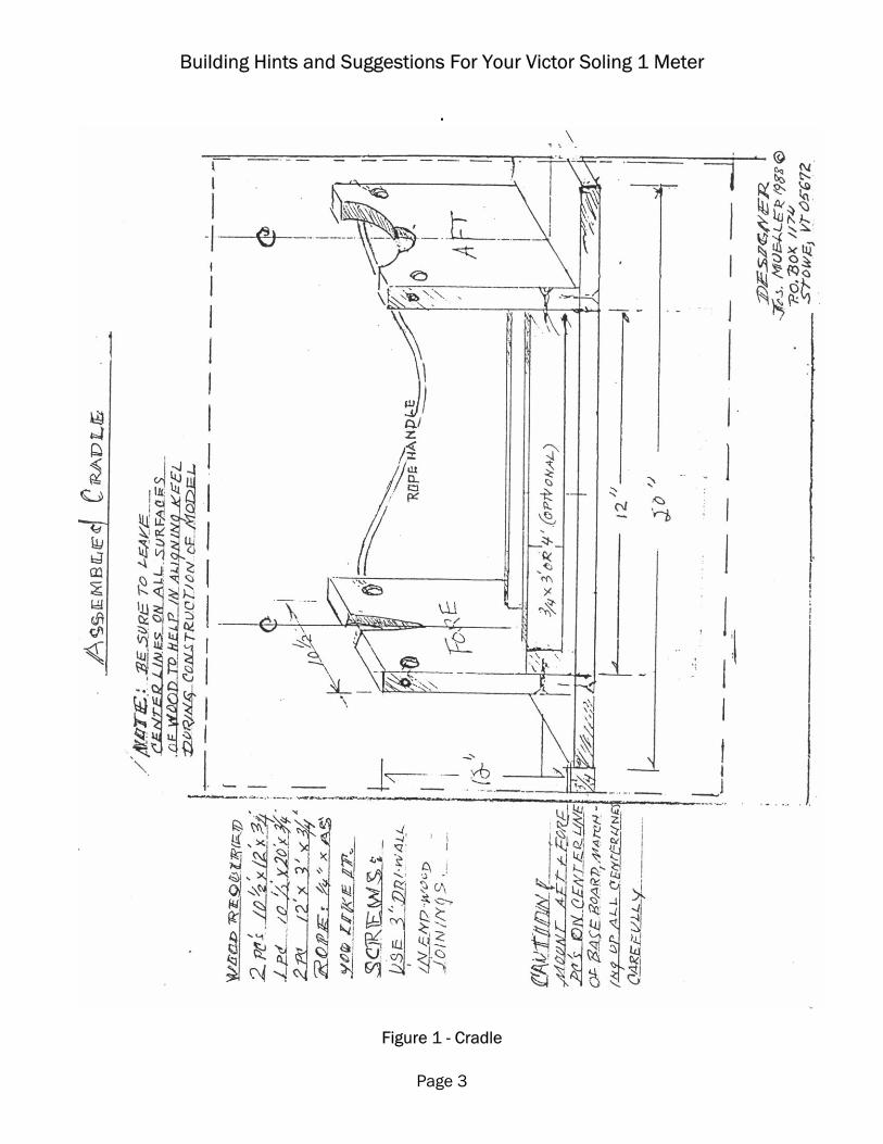
THE KEEL Construction of the keel is a four step assembly process. 1. Attach the keel post to one of the keel halves using five minute epoxy available
from any hardware store. Before you start this gluing process, make sure you thoroughly rough up the area of the keel where the post is to be bonded with course sand paper. Make sure the post is aligned according to the plans and then clamp it firmly. Even though you’re using 5 min. epoxy, it’s smart to let the assembly cure overnight.
Figure 2 - Keel Assembly

Building Hints and Suggestions For Your Victor Soling 1 Meter
Page 5
{Before beginning to assemble the keel it is a good idea to lightly sand both halves on a full sheet of sandpaper glued to a flat board - 150 or 220 grit works well. This will ensure that the halves mate perfectly. –ed}
2. Bond the other side of the keel to the post. Rough this keel half the same way you
did the first before bonding, and again, clamp firmly. The most important part in this step is to make sure that the front, bottom and trailing edges of the keel are aligned exactly. The best way to do this is to smear the epoxy to the keel post, and then align all three sides of the keel halves and tape them together with masking tape, and then clamp. It’s best to let this sit over night.
3. Now you have to glue the keel halves together. Most hardware stores stock glue for plastic models and that’s what you want to use. As glue actually melts the plastic and welds the two pieces being attached. Starting at the top, use a screw driver to separate the halves a little bit so that you can squeeze a bead of glue all around where the two halves meet. You have to glue a little bit, move the screw driver, glue a little bit, move the screw driver, etc., until you’ve gone completely around the keel. Once you’ve finished, use lots of pieces of masking tape all around to make sure that the two halves are sealed.
4. Now you’re ready to pour the lead shot and epoxy to fill the keel. IMPORTANT … Up here we’re using only 6 ¼ pounds of shot … NOT 6 ½ pounds as recommended by Victor. THIS IS A DEPARTURE FROM WHAT IS INDICATED ON THE PLANS. Shot is available at most gun shops. If you can find #8 or #9 shot use it because it’s smaller and compacts better. Most of us have used #6.
{It is getting harder to find the lead shot, but it is available from Victor if all else fails. Rumor has it that the 6 ¼ pound figure here came about because it was not possible to get 3 boats worth of lead from a 25 pound bag of shot. The 4 ounce difference probably comes about because adding the reinforcements included in this document will add some weight, but probably not 4 ounces. Painting the hull can add 2 or 3 ounces more though. If you are a weight weenie you will want a boat as close to 10 pounds as you can get it. You may want to assemble all of your parts and weight them, making allowance for adhesives, BEFORE you pour the keel. –ed.}
You should also understand something about epoxy. Epoxy is a thermosetting plastic. When the resin and the catalyst are mixed, a chemical reaction takes place which changes the liquid to a solid. The faster the reaction takes place, the more heat is built up. If you use a fast setting resin catalyst combination, you can build up so much heat you can melt and deform the keel halves you’re filling. We
Building Hints and Suggestions For Your Victor Soling 1 Meter
Page 6
have found that the WEST SYSTEM with the slow curing hardener gives us no over heating problems. West epoxy can be found in any marine supply store.
OK, now you’ve got this quart can of epoxy and a can of catalyst. You don’t need it all, and they tell you to mix it five to one. Get a thin stick of wood and measure ½” from the end and draw a line. 2 ½” above that line (5 times ½”) draw another line. I use a normal size vegetable can and pour in catalyst to the first line, then resin to the second. This gives you just a little more epoxy than you need. Make sure to mix very well. Now you can bend the can to form a ‘V’ so you can pour from the can directly into the keel. {I’ve found that a small funnel can be helpful here. –ed.}
Pour about ¼ cup of the mixed resin into the keel and slosh it around to wet the inside and bottom. Block the keel so it stands flat on its bottom and pour in about ¼ cup of the shot. Keep alternating shot and epoxy and shot until you’ve used up the shot. You also want to make your pours in front and in back of the keel post. Cut a coat hanger wire so you can poke and tamp the shot down and to get it fairly level. If it isn’t quite level, it’s better to have a little more shot in the front of the keel than in the back. Now all you have to do is fill the keel to the top with the rest of the epoxy. A lot of air bubbles are going to come up as the epoxy fills the voids between the shot so when you look at the thing the next day you’ll see that you have about ¼” more to fill. Make a small amount of epoxy using 5 teaspoons to 1 to fill that last ¼”.
Oh goody – Now you’ve got a keel – It’s a lot heavier than you thought it would be, isn’t it?
{Victor will build you a complete keel if you ask them to and completely eliminate all the fun you’re going to have here. –ed.}
THE HULL – FORWARD BULKHEAD & KEEL BOX ASSMBLY OK, here’s where you build for performance on the water. The keel has to be straight up and down. It has to be aligned axially with the center line of the boat, and it has to be in the right fore and aft position. Pay attention now, it isn’t all that hard. {Victor will build you a complete hull if you ask them to, but we’ve seen some that didn’t line up quite as well as we’d like. It’s a good way to save a lot of time and maybe some aggravation if you’re a first-time builder, or in a hurry. –ed.}
Building Hints and Suggestions For Your Victor Soling 1 Meter
Page 7
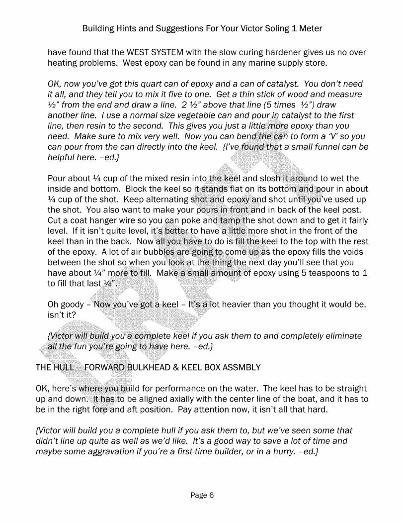
1. See Figure 3 and build this part of the keel box first. Use five minute epoxy and clamp it, then wipe off any excess epoxy that seeps out of the joints or you’ll have to sand it off later.
Figure 3 – Keel Box
{The current keel box is called the ‘keel trunk’ on page 4 of the 7/97 Victor plans and looks different, but the hint about the Q-tip still applies. I recommend leaving the top plate off for now so that you can use the T-jig for alignment of the keel box as described in step 6 of this section. Many of us are permanently mounting the keel with epoxy. The top plate can be added when you do that, or it can be eliminated entirely along with the bolt and wing nut. –ed.}
2. Notch the bulkhead lip as shown in the keel installation instructions on the first
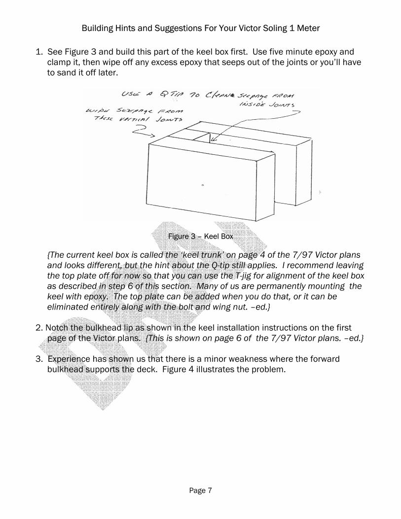
page of the Victor plans. {This is shown on page 6 of the 7/97 Victor plans. –ed.} 3. Experience has shown us that there is a minor weakness where the forward
bulkhead supports the deck. Figure 4 illustrates the problem.
Building Hints and Suggestions For Your Victor Soling 1 Meter
Page 8
Figure 4 – Forward Bulkhead Weakness at Mast Step
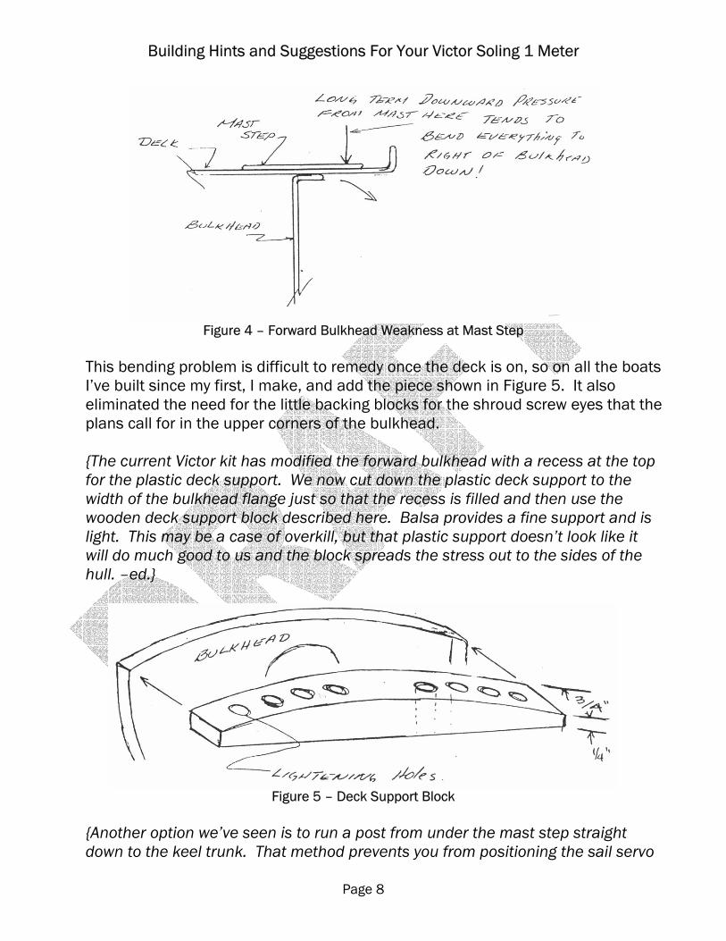
This bending problem is difficult to remedy once the deck is on, so on all the boats I’ve built since my first, I make, and add the piece shown in Figure 5. It also eliminated the need for the little backing blocks for the shroud screw eyes that the plans call for in the upper corners of the bulkhead. {The current Victor kit has modified the forward bulkhead with a recess at the top for the plastic deck support. We now cut down the plastic deck support to the width of the bulkhead flange just so that the recess is filled and then use the wooden deck support block described here. Balsa provides a fine support and is light. This may be a case of overkill, but that plastic support doesn’t look like it will do much good to us and the block spreads the stress out to the sides of the hull. –ed.}
Figure 5 – Deck Support Block
{Another option we’ve seen is to run a post from under the mast step straight down to the keel trunk. That method prevents you from positioning the sail servo
Building Hints and Suggestions For Your Victor Soling 1 Meter
Page 9
as far forward as you might otherwise like. It also restricts access to the forward part of the hull, but that can be remedied with a removable mast jack.. –ed.}
4. Before you cut the slot in the hull for the keel post, you want to get a good straight
line along the center of the bottom of the hull. You have two good reference points. The first is where the hull forms a V in front of the keel, and the second is the center of the dimple in the hull where the rudder post is to be positioned. A thin piece of lath connecting these two points can be used as a straight edge to draw a pencil line connecting them. A third hand is almost a necessity here. Don’t get cute and draw the line faintly. You’re going to need that line when you install the keel permanently and you’re going to handle the hull a lot in the interim. It can and will rub off. I’ve found that I’ve had to go over this line several times before I get the keel installed permanently. Now cut out the 5/16” by 1 ¾” keel slot in the hull. The directions for this are described as the first step in the hull assembly on the second page of the Victor plans.
{The Victor kit now comes with the keel slot already cut, but the center line described in this step is still valuable to have for alignment of the keel trunk and rudder. –ed.}
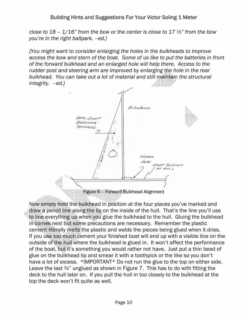
5. You have to install the forward bulkhead in the boat vertically, at right angles to the center line and with its front face exactly 17 ½ inches from the bow. A lot of fiddling goes on here so take your time and be ready for everything to fall apart several times before you get it all lined up and glued. Put the bulkhead in the boat and try to clamp the bulkhead lip to the hull with clothes pins or masking tape. Now measure 17 ½” from the bow to the front face of the bulkhead at the approximate center. Now from the same point at the bow measure back to each side where the hull meets the bulk head. Make these dimensions equal. Now go back and check the 17 ½” dimension. Pretty soon you’ll have that bulkhead at right angles to the center line and 17 ½” back from the bow. Mark the points where the lip of the bulkhead meets the hull at either side at the top. It took a while to find them, and for sure everything is going to go haywire while you get the bulkhead vertical. I have a very small drafting triangle which I use on the flat portion of the hull and I mark where the lip meets the hull on either side of the slot that was cut out for the keel box.
{The 7/97 Victor plans call for the forward bulkhead to be aligned at 18 - 1/16” from the bow to each side of the hull where it meets the bulkhead, not the 17 ½” to the top center as earlier versions of the plans called for. I would recommend following Victor’s step 4 under ‘Hull Assembly’ on page 4 of the plans, then using the small drafting triangle recommended by Curtis to square it up. If the sides are
Building Hints and Suggestions For Your Victor Soling 1 Meter
Page 10
close to 18 – 1/16” from the bow or the center is close to 17 ½” from the bow you’re in the right ballpark. –ed.} {You might want to consider enlarging the holes in the bulkheads to improve access the bow and stern of the boat. Some of us like to put the batteries in front of the forward bulkhead and an enlarged hole will help there. Access to the rudder post and steering arm are improved by enlarging the hole in the rear bulkhead. You can take out a lot of material and still maintain the structural integrity. –ed.}
Figure 6 – Forward Bulkhead Alignment
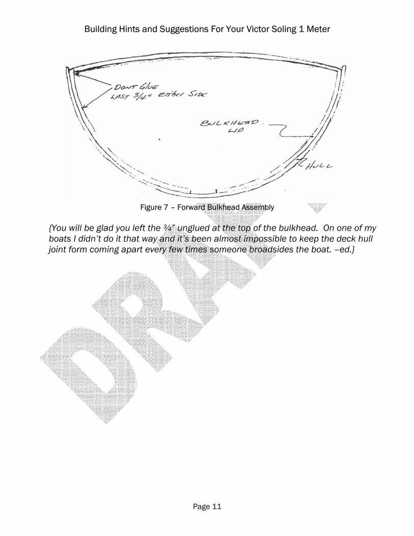
Now simply hold the bulkhead in position at the four places you’ve marked and draw a pencil line along the lip on the inside of the hull. That’s the line you’ll use to line everything up when you glue the bulkhead to the hull. Gluing the bulkhead in comes next but some precautions are necessary. Remember the plastic cement literally melts the plastic and welds the pieces being glued when it dries. If you use too much cement your finished boat will end up with a visible line on the outside of the hull where the bulkhead is glued in. It won’t affect the performance of the boat, but it’s something you would rather not have. Just put a thin bead of glue on the bulkhead lip and smear it with a toothpick or the like so you don’t have a lot of excess. *IMPORTANT* Do not run the glue to the top on either side. Leave the last ¾” unglued as shown in Figure 7. This has to do with fitting the deck to the hull later on. If you pull the hull in too closely to the bulkhead at the top the deck won’t fit quite as well.
Building Hints and Suggestions For Your Victor Soling 1 Meter
Page 11
Figure 7 – Forward Bulkhead Assembly
{You will be glad you left the ¾” unglued at the top of the bulkhead. On one of my boats I didn’t do it that way and it’s been almost impossible to keep the deck hull joint form coming apart every few times someone broadsides the boat. –ed.}
Building Hints and Suggestions For Your Victor Soling 1 Meter
Page 12
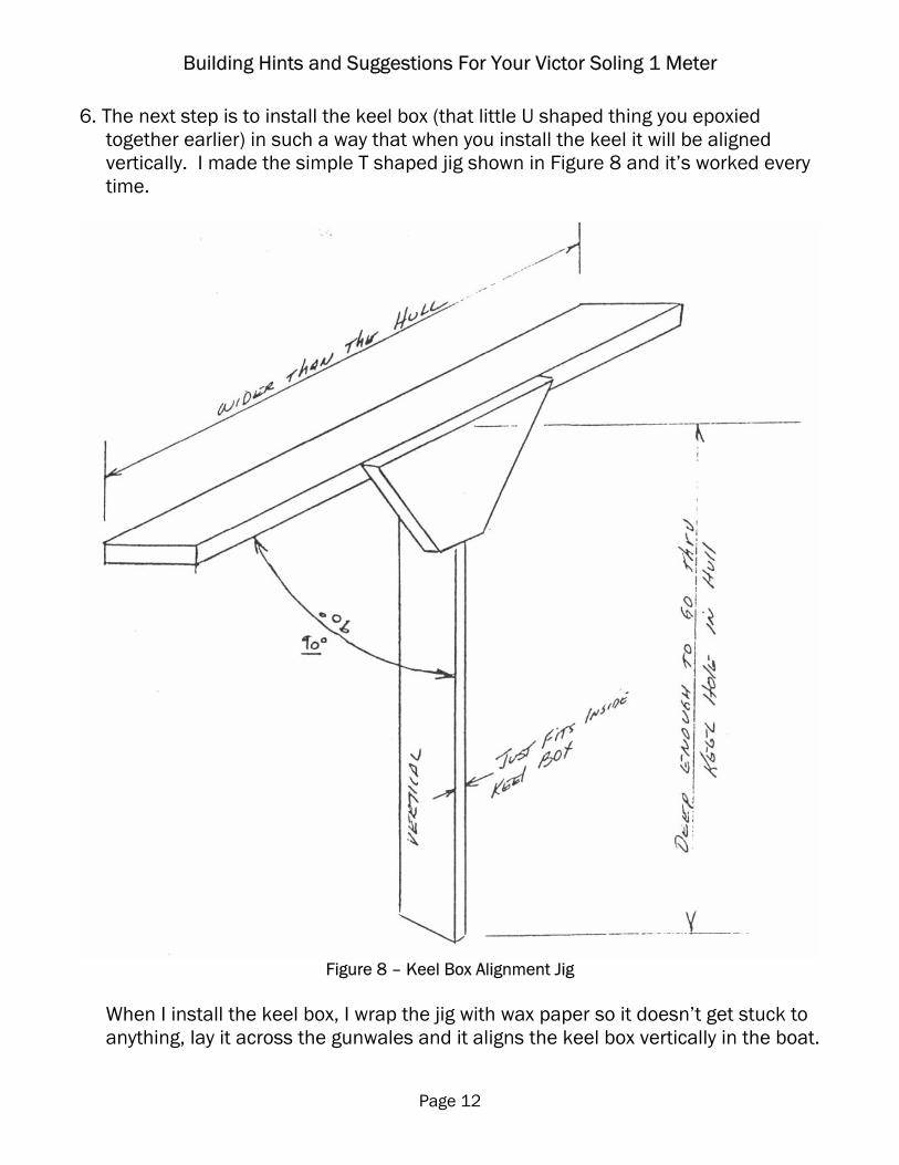
6. The next step is to install the keel box (that little U shaped thing you epoxied together earlier) in such a way that when you install the keel it will be aligned vertically. I made the simple T shaped jig shown in Figure 8 and it’s worked every time.
Figure 8 – Keel Box Alignment Jig
When I install the keel box, I wrap the jig with wax paper so it doesn’t get stuck to anything, lay it across the gunwales and it aligns the keel box vertically in the boat.
Building Hints and Suggestions For Your Victor Soling 1 Meter
Page 13
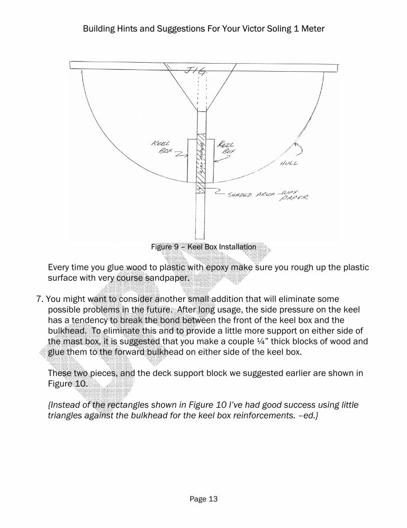
Figure 9 – Keel Box Installation
Every time you glue wood to plastic with epoxy make sure you rough up the plastic surface with very course sandpaper.
7. You might want to consider another small addition that will eliminate some
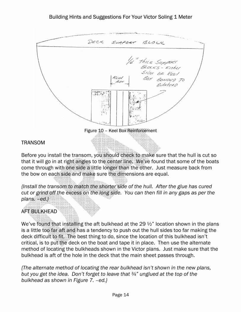
possible problems in the future. After long usage, the side pressure on the keel has a tendency to break the bond between the front of the keel box and the bulkhead. To eliminate this and to provide a little more support on either side of the mast box, it is suggested that you make a couple ¼” thick blocks of wood and glue them to the forward bulkhead on either side of the keel box.
These two pieces, and the deck support block we suggested earlier are shown in Figure 10. {Instead of the rectangles shown in Figure 10 I’ve had good success using little triangles against the bulkhead for the keel box reinforcements. –ed.}
Building Hints and Suggestions For Your Victor Soling 1 Meter
Page 14
Figure 10 – Keel Box Reinforcement
TRANSOM Before you install the transom, you should check to make sure that the hull is cut so that it will go in at right angles to the center line. We’ve found that some of the boats come through with one side a little longer than the other. Just measure back from the bow on each side and make sure the dimensions are equal. {Install the transom to match the shorter side of the hull. After the glue has cured cut or grind off the excess on the long side. You can then fill in any gaps as per the plans. –ed.} AFT BULKHEAD We’ve found that installing the aft bulkhead at the 29 ½” location shown in the plans is a little too far aft and has a tendency to push out the hull sides too far making the deck difficult to fit. The best thing to do, since the location of this bulkhead isn’t critical, is to put the deck on the boat and tape it in place. Then use the alternate method of locating the bulkheads shown in the Victor plans. Just make sure that the bulkhead is aft of the hole in the deck that the main sheet passes through. {The alternate method of locating the rear bulkhead isn’t shown in the new plans, but you get the idea. Don’t forget to leave that ¾” unglued at the top of the bulkhead as shown in Figure 7. –ed.}
Building Hints and Suggestions For Your Victor Soling 1 Meter
Page 15
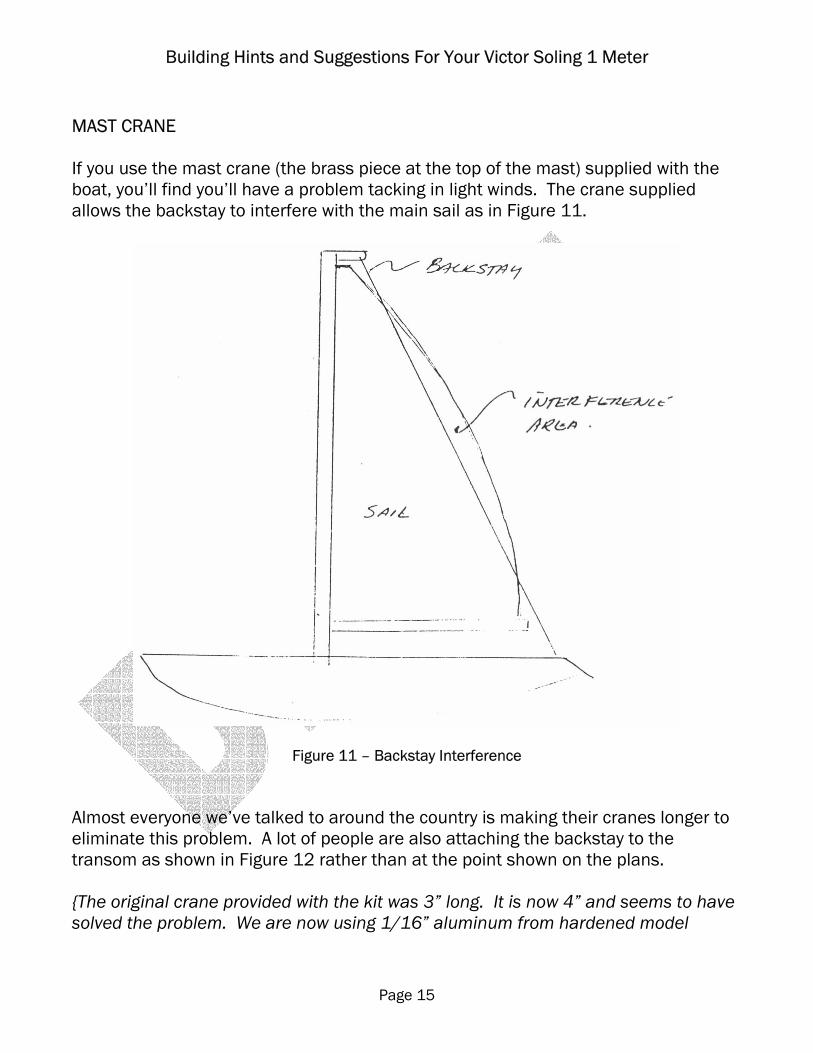
MAST CRANE If you use the mast crane (the brass piece at the top of the mast) supplied with the boat, you’ll find you’ll have a problem tacking in light winds. The crane supplied allows the backstay to interfere with the main sail as in Figure 11.
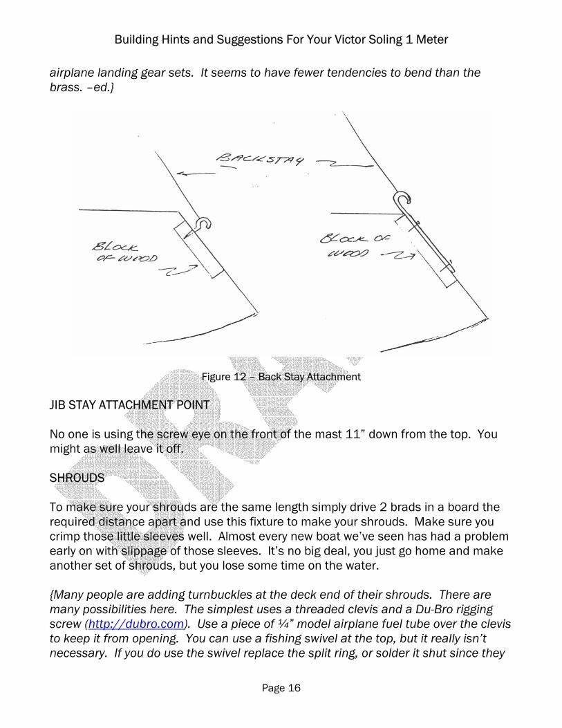
Figure 11 – Backstay Interference Almost everyone we’ve talked to around the country is making their cranes longer to eliminate this problem. A lot of people are also attaching the backstay to the transom as shown in Figure 12 rather than at the point shown on the plans. {The original crane provided with the kit was 3” long. It is now 4” and seems to have solved the problem. We are now using 1/16” aluminum from hardened model
Building Hints and Suggestions For Your Victor Soling 1 Meter
Page 16
airplane landing gear sets. It seems to have fewer tendencies to bend than the brass. –ed.}
Figure 12 – Back Stay Attachment JIB STAY ATTACHMENT POINT No one is using the screw eye on the front of the mast 11” down from the top. You might as well leave it off. SHROUDS To make sure your shrouds are the same length simply drive 2 brads in a board the required distance apart and use this fixture to make your shrouds. Make sure you crimp those little sleeves well. Almost every new boat we’ve seen has had a problem early on with slippage of those sleeves. It’s no big deal, you just go home and make another set of shrouds, but you lose some time on the water. {Many people are adding turnbuckles at the deck end of their shrouds. There are many possibilities here. The simplest uses a threaded clevis and a Du-Bro rigging screw (http://dubro.com). Use a piece of ¼” model airplane fuel tube over the clevis to keep it from opening. You can use a fishing swivel at the top, but it really isn’t necessary. If you do use the swivel replace the split ring, or solder it shut since they

Building Hints and Suggestions For Your Victor Soling 1 Meter
Page 17
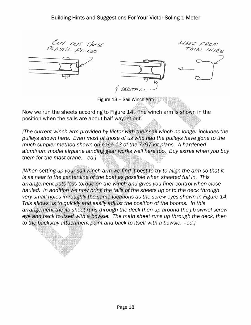
have a tendency to come apart in a good strong wind – exactly when you’d least like it to happen. If you rig this way adjust the mast to vertical and the turnbuckle almost fully extended then crimp on the shroud moderately tight so you have some adjustment as it stretches. –ed.} RADIO BOARD Attached is a full size template for a radio board that works. {The template was never prepared so for now you’re on your own here. We’ll see if we can get a good one soon. –ed.} There are plenty of other layout configurations and you might find one more to your liking in the future. That’s part of the fun of this game, trying to find something that’s a little better than the other guys. This one’s good for a start and it assures that the sail winch clears the front bulkhead. Most hobby shops carry 1/8” plywood and it works fine. Boards can be made from many things - wood, thin plastic, Plexiglas and aluminum have all been used. Installation is also pretty simple, a couple of ¾” by 1/8” strips mounted crosswise to the hull work just fine to screw the board to. {A radio board is now included with the kit and the diagrams there work fine, but that arrangement puts the weight further to the rear of the boat than many of us like. Your goal should be to trim so that the bottom of the transom just barely clears the water. Trimming this way eliminates some drag that exists if the transom is in the water. Mounting the sail servo on the starboard side of the keel trunk and the batteries to port with the rudder servo just behind the keel trunk can help achieve this. It also eliminates some additional weight that can be added to the keel. –ed.} RUNNING THE SHEETS THROUGH THE WINCH Here again, there’s more than one way to do this, but this arrangement works well. You might want to change it after you get some experience. First of all you should notice that the sail winch servo arm is longer on one side than the other. The longer arm is for the main sheet and the shorter, the jib. One other thing most of us have done is to make a small modification to both ends of the sail winch arm as in Figure 12.
Building Hints and Suggestions For Your Victor Soling 1 Meter
Page 18
Figure 13 – Sail Winch Arm
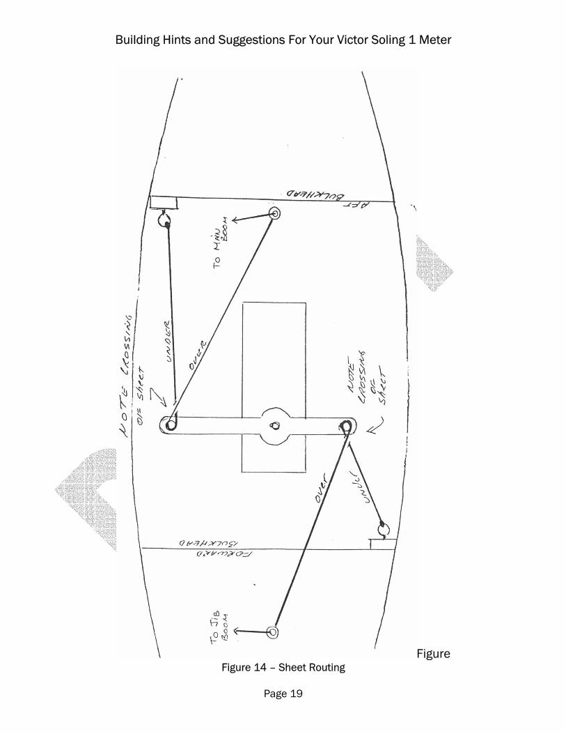
Now we run the sheets according to Figure 14. The winch arm is shown in the position when the sails are about half way let out. {The current winch arm provided by Victor with their sail winch no longer includes the pulleys shown here. Even most of those of us who had the pulleys have gone to the much simpler method shown on page 13 of the 7/97 kit plans. A hardened aluminum model airplane landing gear works well here too. Buy extras when you buy them for the mast crane. –ed.} {When setting up your sail winch arm we find it best to try to align the arm so that it is as near to the center line of the boat as possible when sheeted full in. This arrangement puts less torque on the winch and gives you finer control when close hauled. In addition we now bring the tails of the sheets up onto the deck through very small holes in roughly the same locations as the screw eyes shown in Figure 14. This allows us to quickly and easily adjust the position of the booms. In this arrangement the jib sheet runs through the deck then up around the jib swivel screw eye and back to itself with a bowsie. The main sheet runs up through the deck, then to the backstay attachment point and back to itself with a bowsie. –ed.}
Building Hints and Suggestions For Your Victor Soling 1 Meter
Page 19
Figure Figure 14 – Sheet Routing
Building Hints and Suggestions For Your Victor Soling 1 Meter
Page 20
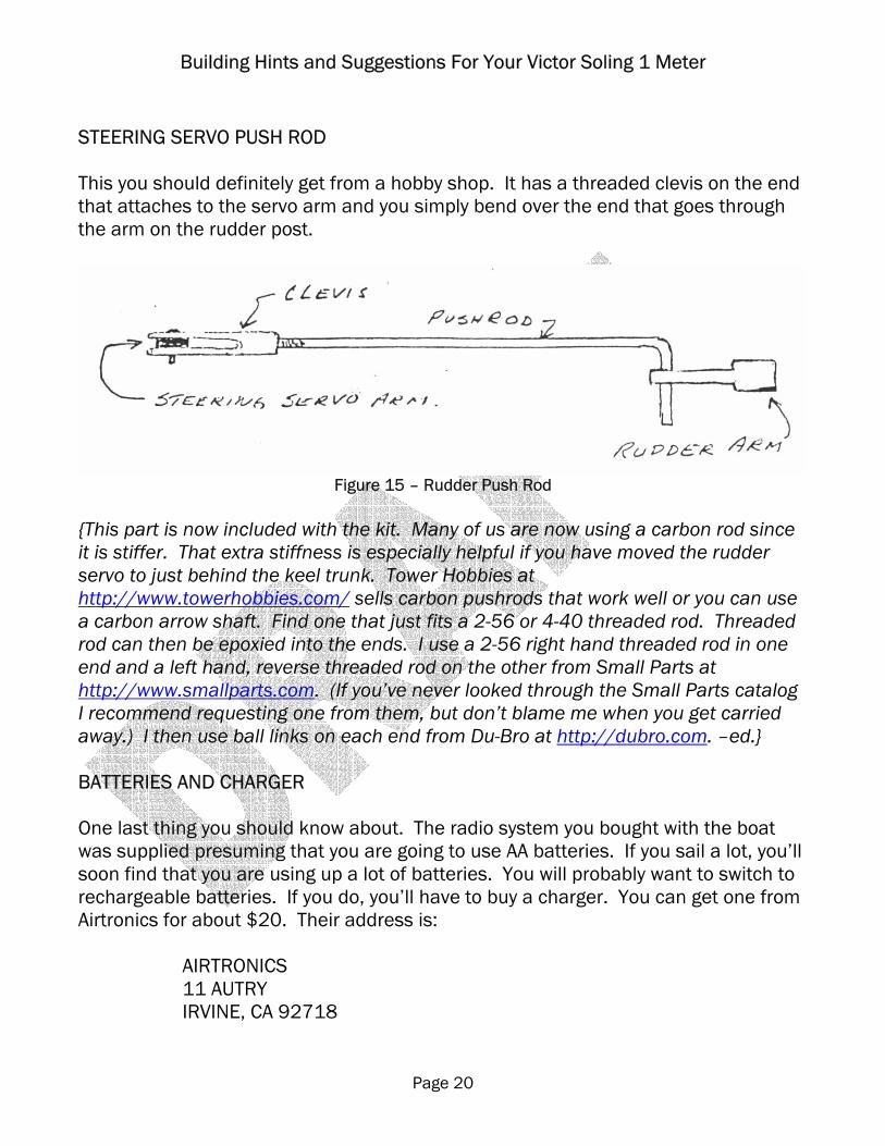
STEERING SERVO PUSH ROD This you should definitely get from a hobby shop. It has a threaded clevis on the end that attaches to the servo arm and you simply bend over the end that goes through the arm on the rudder post.
Figure 15 – Rudder Push Rod
{This part is now included with the kit. Many of us are now using a carbon rod since it is stiffer. That extra stiffness is especially helpful if you have moved the rudder servo to just behind the keel trunk. Tower Hobbies at http://www.towerhobbies.com/ sells carbon pushrods that work well or you can use a carbon arrow shaft. Find one that just fits a 2-56 or 4-40 threaded rod. Threaded rod can then be epoxied into the ends. I use a 2-56 right hand threaded rod in one end and a left hand, reverse threaded rod on the other from Small Parts at http://www.smallparts.com. (If you’ve never looked through the Small Parts catalog I recommend requesting one from them, but don’t blame me when you get carried away.) I then use ball links on each end from Du-Bro at http://dubro.com. –ed.} BATTERIES AND CHARGER One last thing you should know about. The radio system you bought with the boat was supplied presuming that you are going to use AA batteries. If you sail a lot, you’ll soon find that you are using up a lot of batteries. You will probably want to switch to rechargeable batteries. If you do, you’ll have to buy a charger. You can get one from Airtronics for about $20. Their address is:
AIRTRONICS 11 AUTRY IRVINE, CA 92718
Building Hints and Suggestions For Your Victor Soling 1 Meter
Page 21
Their phone number is: 714-830-8769. The part is a 110 volt, 50 MA dual charger #95030 This charger will enable you to charge both the boat batteries and the transmitter batteries at the same time. Another part you might want to get from Airtronics is a larger servo arm for your steering servo. It’s called a “4 point servo arm, extra length” and you can get two of them for about $1.50. The part number is 98323. The best deal we’ve found for the re-chargeable batteries is from a company called Indy R/C. They sell 650 MA AA batteries for about $1.50 apiece. Even with shipping they end up cheaper than you can buy them from the local hardware stores. Indy R/C’s order number is 800-338-4639. {I have not checked the suppliers or availability of the parts listed in this section. -ed.}
Recommended


![Hints on Building a Gingerbread House [ here’s what--And what NOT--to do!]](https://img.dokumen.tips/doc/110x75/56814d79550346895dbad686/hints-on-building-a-gingerbread-house-heres-what-and-what-not-to-do.jpg)

