53-0000231-05
1 of 69
Brocade SAN DesignGuide

53-0000231-05
2 of 69
Table of Contents
Preface............................................................................................................................................ 5
Section 1 : Overview of SAN Design........................................................................................ 6
The Brocade Product Line .......................................................................................................... 6
SilkWorm 2000....................................................................................................................... 6
SilkWorm 3000....................................................................................................................... 6
SilkWorm 6400....................................................................................................................... 7
SilkWorm 12000..................................................................................................................... 9
Design Considerations ................................................................................................................ 9
Design Terminology ................................................................................................................. 10
SAN Solutions .......................................................................................................................... 11
Storage Consolidation........................................................................................................... 12
LAN-Free Backup................................................................................................................. 13
Clustering.............................................................................................................................. 15
Summary................................................................................................................................... 15
Section 2 : SAN Design Concepts........................................................................................... 16
Availability ............................................................................................................................... 16
Availability Classifications................................................................................................... 17
Resilient Fabrics.................................................................................................................... 18
Redundant Fabrics ................................................................................................................ 19
Scalability ................................................................................................................................. 21
Performance .............................................................................................................................. 24
Blocking and Congestion...................................................................................................... 24
Locality ................................................................................................................................. 25
ISL Over-Subscription .......................................................................................................... 26
Bandwidth Consumption and Congestion ............................................................................ 28
I/O Profiles............................................................................................................................ 30
Device Attachment Strategies................................................................................................... 34
Performance and Scalability Effects..................................................................................... 34
Tiered Fabrics ....................................................................................................................... 35
High Locality Device Attachment ........................................................................................ 38

53-0000231-05
3 of 69
Section 3 : Fabric Topologies ................................................................................................. 39
Simple Topologies .................................................................................................................... 39
Cascade ................................................................................................................................. 39
Ring....................................................................................................................................... 40
Full Mesh .............................................................................................................................. 41
Partial Mesh .......................................................................................................................... 42
Core/Edge ............................................................................................................................. 44
Hybrid Topologies .................................................................................................................... 46
Complex Core ....................................................................................................................... 47
Composite Core/Edge ........................................................................................................... 47
Summary............................................................................................................................... 48
Section 4 : Switch Platform Considerations.......................................................................... 50
Port Count ................................................................................................................................. 50
ISL TrunkingTM......................................................................................................................... 50
What Is Trunking? ................................................................................................................ 50
How Does Trunking Impact SAN Design? .......................................................................... 52
How 2 Gbit/sec Switches Impact a SAN Design...................................................................... 53
2 Gbit/sec Switch Placement ................................................................................................ 53
More Ports or Higher Performance? ..................................................................................... 54
Cabling For High Availability .................................................................................................. 55
SilkWorm 12000 Device Attachment Strategies .................................................................. 56
SilkWorm 12000 Availability Considerations...................................................................... 57
Section 5 : Testing and Fabric Support Levels..................................................................... 58
Section 6 : Reference Topologies............................................................................................ 59
16-Port Switch Designs............................................................................................................. 60
56-Port Fabric ....................................................................................................................... 60
96-Port Fabric ....................................................................................................................... 61
160-Port Fabric ..................................................................................................................... 62
224-Port Fabric ..................................................................................................................... 62
Extended Distance Topology................................................................................................ 63
64-Port Switch Designs............................................................................................................. 64
64-Port Fabric ....................................................................................................................... 64
124-Port Fabric ..................................................................................................................... 65

53-0000231-05
4 of 69
248-Port Fabric ..................................................................................................................... 66
368-Port Fabric ..................................................................................................................... 67
16- and 64-Port Switch Mixed Designs .................................................................................... 68
440-Port and 512-Port Fabrics .............................................................................................. 68
Copyright ..................................................................................................................................... 69

53-0000231-05
5 of 69
Preface
No matter how big a single switch might be, eventually a requirement for one more port than thatswitch supports will arise. This “n+1” problem is solved with networking. All Storage AreaNetwork (SAN) designs should involve planning for networks of switches, even if they do nothave network requirements initially. The Brocade SAN Design Guide discusses factors thatinfluence fabric topology and overall SAN architecture, and facilitates storage network design byexplaining:
• When and how to connect fabric switches together
• When to leave them unconnected
• The pros and cons of different SAN architectures and fabric topologies
The target audience for this document consists of technical professionals responsible for thedesign, implementation, and administration of SANs. It focuses on delivering essentialinformation that is necessary to design a Brocade SAN. While many of the design parametersdiscussed here are wide-ranging, these topics are examined here only to the extent that eachaffects SAN design.
To obtain additional background on SANs and SAN design, see the book Building SANs withBrocade Fabric Switches (published by Syngress press ISBN: 1-928994-30-x). This book offersmore detailed information on a wider range of SAN topics.It is important to have a working knowledge of Brocade SANs to effectively use this guide. TheBrocade Educational Services series of courses is an excellent resource for those new to SANsand for more experienced designers who want to keep their skills sharp. You can find out moreabout Brocade Educational Services on the Brocade web site:www.brocade.com/education_services.

53-0000231-05
6 of 69
Section 1: Overview of SAN Design
The first part of this section is devoted to descriptions of the Brocade product line.
The second part provides a high-level discussion of requirements that can affect SAN design.
The final part is devoted to a discussion of SAN terminology. The terms and definitionsprovided form the foundation of SAN design terminology used throughout this document. Manyof the SAN design approaches discussed in this document are similar to techniques used in otherareas of computer and network design. For example, the core/edge topology described inSection 3 is reminiscent of the star topology common in Ethernet networks.
The third part briefly discusses several solutions that can be built using SANs and how theseparticular solutions influence a SAN design. These solutions are described in further detail inBrocade’s SOLUTIONware series of technical briefs, available fromhttp://www.brocade.com/san/solutionware.jhtml.
The Brocade Product Line
SilkWorm 2000The SilkWorm 22x0 and the SilkWorm 20x0 switches have a single power supply and do nothave hot swappable fans. The SilkWorm 2400 and the SilkWorm 2800 implement hot swap andredundant power supplies, delivering increased availability levels. The SilkWorm 20x0 andSilkWorm 2400 switches are 8-port switches and the SilkWorm 22x0 and the SilkWorm 2800are 16-port switches. The SilkWorm 2000 series of switch utilize a v2.x version of Fabric OS.To ensure maximal functionality and scalability, v2.6.x or higher should be used. .
SilkWorm 3000The SilkWorm 3000 series of switches utilize an advanced ASIC technology that enablesadvanced SAN features such as trunking and frame filtering. Frame filtering enables moregranular levels of zoning and end-to-end performance monitoring. The SilkWorm 3000 series ofswitches are capable of 2 Gbit/sec speeds. The SilkWorm 3800 is a 16-port switch configuredwith redundant power supplies and fans. The impacts 2 Gbit/sec, port count, and trunking upon aSAN design are discussed earlier in this section and it is suggested to place these switchesadjacent to each other or in the core of a core/edge topology, as shown in Figure 32. TheSilkWorm 3000 series of switch utilize a v3.x version of Fabric OS, which is backwardscompatible with v2.x versions of firmware. The size of fabric built should take into considerationthe support limits of a particular Fabric OS version, which are identified in Section 5. TheSilkWorm 3800 enables the creation of very dense fabrics in relatively small space due to its 1Uheight.

53-0000231-05
7 of 69
Figure 1. Place the SilkWorm 3800 in the Core of a Core/Topology
3800
38003800
3800
38003800
2800
2800
2800
2800
1 Gb/s ISL4 Gb/s Trunk
SilkWorm 6400The SilkWorm 6400 is a SilkWorm 2250 based integrated fabric. The switches are connected ina core/edge topology. The SilkWorm 6400 uses six domains – one for each switch in theintegrated fabric. The SilkWorm 6400 utilizes a v2.4.1x or greater version of Fabric OS. The sizeof fabric built should take into consideration the support limits of a particular Fabric OS version,which are identified in Section 5. When connecting other switches to the SilkWorm 6400 orinterconnecting multiple SilkWorm 6400s, there are some guidelines for doing so. The switchesnumbers 1 and 6 are core switches (see Figure 2). When adding devices to the SilkWorm 6400, itis recommended to place the devices on edge switches 2, 3, 4, and 5 first. When devices areplaced on the core switches (switches 1 and 2), it limits scalability and performance (see DeviceAttachment Strategies in Section 2 for the reasons why).
Figure 2. SilkWorm 6400 Switch Functions and Locations
Switch 1 Switch 6
1 6
2 3 4 5
1 2 3 4 5 6
Cores
Edge Switches

53-0000231-05
8 of 69
When adding switches to expand the fabric, connect those switches to the SilkWorm 6400 coreswitches. Doing so preserves the balanced performance characteristics of the core/edge topology.It is not necessary to attach each new edge switch with two ISLs to each core switch unlessperformance requirements dictate. If a single ISL is used to attach each edge switch to each coreof the SilkWorm 6400, it is possible to create a 160-port fabric as shown in Figure 3.
Figure 3. Expanding the SilkWorm 6400 by Adding Switches to the Core
6400
Addional Swithces
When connecting multiple SilkWorm 6400s together, it is most efficient to connect theSilkWorm 6400s at the cores, as shown in Figure 4. The topology shown in Figure 4 is aneffective one for joining two SilkWorm 6400s that are separated by a distance or to build a largerfabric.
Figure 4. Connecting SilkWorm 6400s Together
Connecting ISLs
6400
6400

53-0000231-05
9 of 69
SilkWorm 12000The SilkWorm 12000 has a bladed architecture. Each chassis contains up to 128 ports, each ofwhich runs at either 1 or 2 Gbit/sec. These ports are divided into two logical 64-port switches.The same advanced ASIC technology introduced in the SilkWorm 3800 is used in the SilkWorm12000, with the same advanced features supported, and high availability/failover features havebeen added as well. A new Fabric OS (version 4.0) is used on the SilkWorm 12000.
There are quite a few impacts to SAN design when using a SilkWorm 12000. Some are obvious:if a 64-port solution is desired, no network is required. For large fabrics, fewer switches arerequired. Some implications are less obvious. In order to attach a SilkWorm 2000 or 3000series switch to a SilkWorm 12000 network, new firmware might be required on those switches.In addition, some configuration parameters (e.g. Core Switch PID Format) may need to bechanged. For a comprehensive discussion of the impacts to SAN design of using the SilkWorm12000, please see the Brocade SilkWorm 12000 Design, Deployment, and Management Guide(53-0000251-xx).
Note: When deploying the SilkWorm 12000 into existing fabrics that also include SilkWorm2000 and 3000 series switches, it is necessary to change the Core Switch PID format setting onthose switches. Doing so may have an impact on existing applications, as enabling this settingwill change the 24-bit address. Using a redundant fabric architecture can mitigate or eliminatethis impact.
Design ConsiderationsSANs are built in order to solve business problems. The problem statement could be: “Ournightly backups don’t complete within the allowable window, so we need them to run faster” or“We need to optimize our storage utilization since we are becoming short on data center floorspace.” When evaluating the following list of design considerations, keep in mind that theoverriding concept is always the same: a SAN solution must solve the business problem thatdrove the creation of a SAN in the first place. In order to be effective, a SAN solution should:
• Solve the underlying business problem.
• Meet business requirements for availability and reliability1.
• Provide the appropriate level of performance.
• Be effectively manageable.
• Be scalable and adaptable to meet current and future requirements.
• Be cost effective.
• Improve operational control of storage infrastructure.
What is the correct level of performance? It might – and indeed usually does – vary from host tohost within an organization. What does “effectively manageable” mean? If an enterprisemanagement environment is already in place, it could mean integrating SAN management intothat environment or it might mean that it is necessary to evaluate SAN-specific managementpackages to get the required tools. These and other requirements must be well thought out beforethe design is created.
1 Note that SANs may require higher availability than any individual attached node requires in order to meet theavailability goals of the overall organization.

53-0000231-05
10 of 69
Design TerminologyThese terms and definitions are provided to ensure that a consistent language for describingSANs is used throughout the document and so that the reader understands what these termsmean. This section is not intended to be all-inclusive. For example, latency is briefly definedhere, but its significance is not discussed until later.
Blocking: The inability of one device to connect to another device. Brocade’s Virtual Channelimplementation of Fibre Channel does not block. The term blocking is often confused with theterm congestion.Congestion: If two or more sources contend for the same destination, performance for eachsource may decrease; however, available bandwidth is shared fairly by all sources contending forthe same destination. Congestion is the realization of the potential of over-subscription.Congestion may be due to contention for a shared storage port or host port, or an ISL.
Core Switch: Also known as a “core fabric switch.” This is one of the switches at the logicalcenter of a core/edge fabric. There are generally at least two core switches per core/edge fabric toenable resiliency within the fabric. Ports on a core switch are normally used for ISLs.
Edge Switch: This is one of the switches on the logical outside edge of a core/edge fabric.There are generally many more edge switches than core switches. Ports on edge switches areoften used for node connections.
Fabric: One or more interconnected Fibre Channel switches. The term “Fabric” only refers tothe interconnected switches, not to nodes or devices connected to the fabric.
Fabric Topology: A topology is “the logical layout of the components of a computer system ornetwork and their interconnections.” A fabric topology is the layout of the switches that form afabric.
Fabric Port Count: The number of ports available to connect nodes in a fabric. ISLs ports (E-ports) are not included in this count.
Fan-in: The ratio of storage ports to a single host port.
Fan-out: The ratio of host ports to a single storage port.
FSPF: Fabric Shortest Path First protocol. The FSPF protocol was developed by Brocade andsubsequently adopted by the Fibre Channel standards community for allowing switches todiscover the fabric topology and route frames correctly. It is now the industry standard routingprotocol for Fibre Channel networks.
Hop Count: For evaluating SAN designs, the hop count is identical to the number of ISLs that aframe must traverse to reach its destination.
ISL: Inter-Switch Link. ISLs connect two switches via E-ports.
ISL Over-Subscription Ratio: In networks where all ports operate at the same speed, the over-subscription ratio for an ISL is the number of different ports that could contend for the use of itsbandwidth. If there are 14 node ports on a switch and 2 ISLs, the ratio is 14:2, or 7:1. Whenthere is a mixture of port speeds, the exact calculation can become unnecessarily complex. Thiswill be discussed later. The rule of thumb is that the lower the ratio is, the better performance islikely to be. However, in most environments, designing for a ratio lower than 7:1 does notprovide greater real-world performance; it just adds cost.
Latency: The time it takes for a frame to traverse from its source to its destination is referred toas the latency of the link. Sometimes a frame is switched from source to destination on a singleswitch and other times a frames must traverse several hops between switches before it reaches itsdestination.

53-0000231-05
11 of 69
Locality: The degree that I/O is confined to a particular switch or segment of a fabric. If twodevices that need to communicate with each other are located on the same switch or fabricsegment, then these two devices are said to have high locality. If these same devices are locatedon different switches or segments of a fabric and these two devices need to communicate witheach other, then these devices are said to have low locality.
Node: Any SAN device – usually either a host or storage device – that attaches to a fabric.
Node Count: The number of nodes attached to a fabric.
Over-Subscription: A condition where more nodes could potentially contend for the use of aresource – such as an ISL – than that resource could simultaneously support, that resource is saidto be over-subscribed.
Radius: The greatest “distance” in hops between any edge switch and the center of a fabric canbe thought of at that fabric’s radius. Low radius networks have lower hop counts and latency thanhigh radius fabrics. The unit of measurement for a fabric radius is hops.
Resilience: The ability of a fabric to adapt to or tolerate a failure of a component.
SAN: A Storage Area Network (SAN) can consist of one or more related fabrics and theconnected nodes.
SAN Architecture: The overall design or structure of a storage area network solution. Thisincludes one or more related fabrics, each of which has a topology. Other components may alsobe included, such as host, storage, and other SAN devices.
SAN Port Count: The number of ports available for connection by nodes in the entire SAN. TheSAN Port Count equals the fabric port count in a single fabric SAN and is equal to the sum ofeach fabric’s port count in a multi-fabric SAN.
Scalability: The ease with which a particular design can grow and adapt without requiring asignificant change in architecture or requiring a substantial re-layout of existing nodes.
SPOF: A single point of failure. A SPOF in a SAN is any component – either hardware orsoftware – that could cause a fabric or a SAN to fail.
Tiering: The process of grouping particular SAN devices by function and then attaching thesedevices to particular switches or groups of switches based on that function
SAN SolutionsThe adoption of SANs is being driven by a variety of objectives. Some examples are:
• The need for more efficient usage of enterprise storage arrays
• Decreasing size of backup/restore windows
• Increasing size of data set to be backed up
• The need for improved high availability and disaster tolerance solutions
• The need to enhance storage resource management
While many SAN users begin their SAN experience with one particular SAN solution, the SANquickly becomes the basis for many other applications. For example, a company may start outwith SAN-based backup and very quickly integrate storage consolidation and clustering into theexisting SAN foundation. In that respect, a SAN decision is a strategic one, and should receivean appropriate level of attention.
Three of the most popular SAN solution categories are Storage Consolidation, LAN-FreeBackup, and High Availability. Each of these SAN solutions are generically described below and

53-0000231-05
12 of 69
key attributes of each are discussed in terms of their affect on SAN design. For a more detaileddiscussion regarding the configuration, design, and implementation of a SAN solution, referenceBrocade SOLUTIONware, which is available from:http://www.brocade.com/san/solutionware.jhtml.
Storage ConsolidationStorage consolidation is a way of optimizing storage resource utilization. It is often the result ofmigrating directly attached storage (DAS) and hosts to a SAN environment. In a SAN, it is nolonger necessary to have a one-to-one correspondence between a host port and a storage port.Instead, many hosts can share a single storage port, and a single host port can access manystorage devices. This immediately reduces cost on hosts because fewer HBAs are needed, and onstorage because fewer controllers are needed. In addition, savings can accrued by reducingstorage management, power, cooling, and, floor space costs. However, the greatest savingscomes from improved utilization of free space on enterprise storage subsystems. With thelowering cost of FC HBA and switch infrastructure, the storage consolidation value propositionhas never been better.
Assume that 20 hosts each have 100 GB of storage in a direct attach environment, requiring atotal 2000 GB of storage. Some space on each system is free. This is known as white space, orheadroom. The average utilization of this directly attached storage (DAS) is 50%, leaving 50%white space. The total storage utilized is 1200 GB, which leaves 800 GB of white space.
With the use of a SAN, it is possible to achieve much higher utilization since every host hasaccess to all storage in the SAN. In this example, a modest 10-20% improvement in storageutilization could result in a savings of several hundred GB of storage. In addition, a reduction inassociated ownership costs of that surplus storage would occur. In the storage consolidationmodel, if a host is not using all of its storage, it is possible to rapidly reallocate this extra storageto a different host. It is also possible to add additional storage for all servers to access, ratherthan having to purchase storage for specific hosts. In a direct attach environment, it is moredifficult to do so, forcing the need to have very high white space overhead to allow growth. Aconservative 60% utilization scenario with DAS and storage consolidation environments arecompared in Figure 5.

53-0000231-05
13 of 69
Figure 5. Direct Attach / Storage Consolidation Comparison
Storage Host
SAN60
%ut
iliza
tion
80% utilization
Since many hosts depend upon continuous access to their storage in a storage consolidationsolution, designing a highly available SAN to ensure this continuous access is critical. Resilientand redundant fabric designs are highly recommended, especially in large storage consolidationsolutions. These topics are discussed further in Section 2 under Availability on page 16.
In a storage consolidation solution, many devices contend for a shared storage port. Theperformance-limiting factor is often the over-subscription or fan-out ratio of that port, and notthe network. Because of this, it is possible to design SANs with a certain amount of over-subscription without adversely affecting application performance. The relationship betweenapplications, SAN design, and performance is explored further in Section 2.
Because the benefits of storage consolidation grow proportionally with the number of hosts andstorage, the capability for a SAN to scale is important. You can choose a SAN architecture thatcan grow from tens of ports to hundreds, and in some cases, thousands of ports, whileminimizing or eliminating downtime. Topologies such as the core/edge are optimal for enablingthis type of scaling. A discussion of fabric topologies and multi-fabric architectures is presentedin Section 3.
LAN-Free BackupA SAN-based backup is, in some respects, a form of storage consolidation in that an I/O device(the tape drive) is available to be shared by many hosts. The difference is that the shared deviceis tape, rather than disk. This distinction can affect SAN design in several ways:
• Currently, tape libraries tend to be single-attach, so the multi-pathing approaches used instorage consolidation will usually not work.
• Backup devices tend to be more sensitive to I/O disruption than disk arrays. Arrays canrecover from small glitches; tape solutions sometimes do not recover as easily. This is aknown issue in the industry and something being addressed with the emergence andadoption of the FC-TAPE standard.

53-0000231-05
14 of 69
• The availability of tape drives is usually not as critical as that of disk arrays.
• Per-port performance requirements are usually lower for tape than for disk.
Non-SAN based backups take the form of direct attach tape drives, or backup over IP networks.IP backups contend with the normal day-to-day traffic already on the Local Area Network(LAN). Using direct attach tape on each host is costly because of the number of tape devices,tape management, and increased infrastructure cost for floor space, power, cooling, etc.
High-speed SAN-enabled backups reduce backup and restore windows and can enable disaster tolerance bylocating libraries at remote sites. SAN based backup improves on traditional backup by enabling the sharingof fewer, larger tape libraries and by minimizing or eliminating the performance issues associated withtraditional backup architectures, as depicted in
Figure 6. It is also effective to leverage the performance capabilities of Fibre Channel by runningbackups in more traditional mode by backing up clients via IP over Fibre Channel (IPFC) tobackup server, which in turn then writes the data to tape via SCSI over Fibre Channel (FCP).
Figure 6. Direct attach and LAN based backup compared to a SAN based backup
Tape Host
Ethernet
SANor
A disruption in a backup SAN is usually not as critical as a disruption in a storage consolidationSAN. Mission critical applications require continuous access to storage, while a tape backupnormally can be restarted without end users seeing the effect. Therefore, a SAN architecturesolely used for backups may not require the highest availability enabled by a dual fabricarchitecture, and a single resilient fabric may provide sufficient availability. Core/edge, mesh,and ring topologies are all candidates for a backup SAN.

53-0000231-05
15 of 69
ClusteringHigh-availability (HA) clusters are used to support critical business applications. They provide aredundant, fail-safe installation that can tolerate equipment, software, and/or network failures,and continue running with as little impact upon business as possible.
HA clusters have been in use for some time now. However, until the advent of Fibre Channel,they were very limited in size and reliability. This is because clusters require shared storage, andsharing SCSI storage subsystems is difficult and unreliable. In fact, sharing a SCSI devicebetween more than two initiators is completely impractical due to SCSI cabling limitations, andSCSI’s poor support for multiple initiators.
Clustering technology has therefore been greatly enhanced by the network architecture of SANs.SANs provide ease of connectivity, and the ability to interconnect an arbitrarily large number ofdevices. SANs can support as few as two hosts in a failover configuration, and can be expandedto support “many-to-one” configurations. The primary advantages that a SAN affords a clusterare connectivity, scalability, and reliability.
SummarySAN design can appear to be a challenging task, due to the large number of variables involved inpicking an appropriate design strategy. The key to a successful SAN design is to thoroughlydefine the requirements of the solution(s), which the SAN will support. This understanding willmake it possible to choose appropriate design from those discussed in the following sections.
53-0000231-05
16 of 69
Section 2: SAN Design Concepts
Several SAN design concepts are discussed in depth in this section to provide a foundation fordescribing a fabric topology or SAN architecture in more detail. These key concepts are:availability, scalability, and performance. To effectively describe these SAN design concepts, itis necessary to refer to certain topologies, which are detailed further in Section 3.
Differing levels of detail can be given on any networking topic. This guide takes a middle-of-the-road approach. Most of the important concepts are given, and topologies are listed at the endof the guide for quick reference. For a more detailed discussion of SAN design, see chapters 5and 7 in Building SANs with Brocade Fabric Switches from Syngress Press. For a less detailedapproach, see the Sales Guide to SAN Design (part number 53-0000253-xx) on Brocade’s website.
AvailabilityA computer system or application is only as available as the weakest link. To build a highlyavailable computer system it is not sufficient to only have a highly available SAN. It is necessaryto account for availability throughout the entire computer system: dual HBAs, multi-pathingsoftware, highly available and multi-ported storage subsystems, and clustering software are someof the components that may make up such a system.
When building a highly available computer system, use redundant components. One of anythingis not HA. Webster’s dictionary provides the following definition for the word redundant:
Redundant: serving as a duplicate for preventing failure of an entire system (as aspacecraft) upon failure of a single component
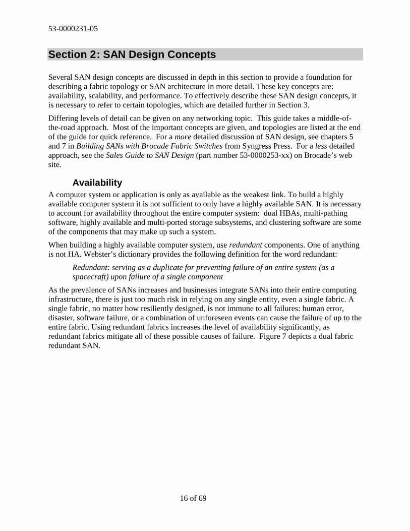
As the prevalence of SANs increases and businesses integrate SANs into their entire computinginfrastructure, there is just too much risk in relying on any single entity, even a single fabric. Asingle fabric, no matter how resiliently designed, is not immune to all failures: human error,disaster, software failure, or a combination of unforeseen events can cause the failure of up to theentire fabric. Using redundant fabrics increases the level of availability significantly, asredundant fabrics mitigate all of these possible causes of failure. Figure 7 depicts a dual fabricredundant SAN.
53-0000231-05
17 of 69
Figure 7. A Resilient/Redundant SAN Architecture
SAN A SAN B
Storage
Hosts
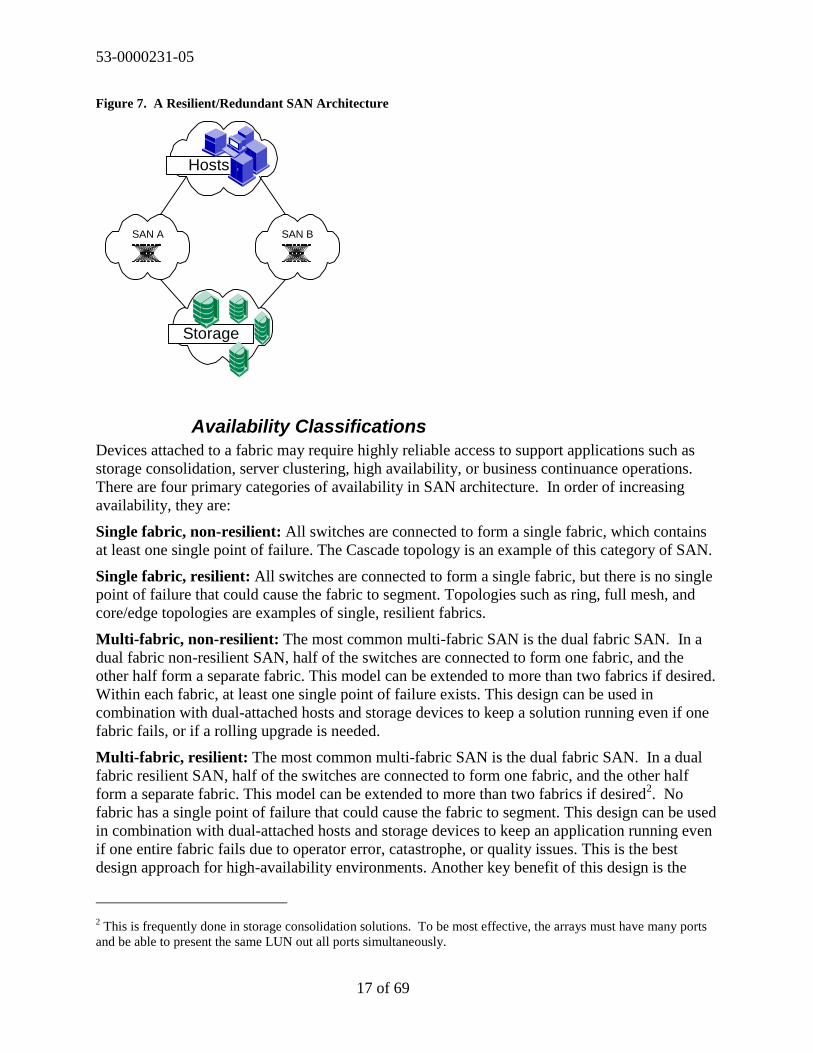
Availability ClassificationsDevices attached to a fabric may require highly reliable access to support applications such asstorage consolidation, server clustering, high availability, or business continuance operations.There are four primary categories of availability in SAN architecture. In order of increasingavailability, they are:
Single fabric, non-resilient: All switches are connected to form a single fabric, which containsat least one single point of failure. The Cascade topology is an example of this category of SAN.
Single fabric, resilient: All switches are connected to form a single fabric, but there is no singlepoint of failure that could cause the fabric to segment. Topologies such as ring, full mesh, andcore/edge topologies are examples of single, resilient fabrics.
Multi-fabric, non-resilient: The most common multi-fabric SAN is the dual fabric SAN. In adual fabric non-resilient SAN, half of the switches are connected to form one fabric, and theother half form a separate fabric. This model can be extended to more than two fabrics if desired.Within each fabric, at least one single point of failure exists. This design can be used incombination with dual-attached hosts and storage devices to keep a solution running even if onefabric fails, or if a rolling upgrade is needed.
Multi-fabric, resilient: The most common multi-fabric SAN is the dual fabric SAN. In a dualfabric resilient SAN, half of the switches are connected to form one fabric, and the other halfform a separate fabric. This model can be extended to more than two fabrics if desired2. Nofabric has a single point of failure that could cause the fabric to segment. This design can be usedin combination with dual-attached hosts and storage devices to keep an application running evenif one entire fabric fails due to operator error, catastrophe, or quality issues. This is the bestdesign approach for high-availability environments. Another key benefit of this design is the
2 This is frequently done in storage consolidation solutions. To be most effective, the arrays must have many portsand be able to present the same LUN out all ports simultaneously.

53-0000231-05
18 of 69
ability to take part of the SAN offline for rolling upgrades or maintenance without affectingproduction operations on the remaining fabric(s). Thus, upgrades can be performed without pathdowntime.
Both resilient and non-resilient dual fabrics can be referred to as “redundant fabric SANs.”Redundant designs are always recommended for HA systems, and any large SAN deploymentwhere downtime for the entire SAN could affect hundreds of servers.
Resilient FabricsMany fabric topologies are available that that provide at least two internal fabric routes betweenall switches that comprise that fabric. These topologies are considered resilient because eachtopology can withstand a switch or ISL failure while the remaining switches and overall fabricremain operational. This self-healing capability is enabled by the Brocade-authored FabricShortest Path First (FSPF) protocol3.
Figure 8 depicts the failure of a switch in a Cascade topology. Switches A and B are unable tocommunicate with the remaining switches when the switch marked with the “X” fails, resultingin the fabric segmenting into three separate fabrics. However, a switch failure in a Ring,core/edge, or other resilient topology fabric does not cause a loss of communication with theremaining switches, as shown in Figure 9. If switch B fails, switch A can still communicate withswitch C through the alternate path indicated by the arrows. The fail over to alternate paths iseffectively transparent to the attached devices. This fail over is performed by FSPF, whichautomatically reroutes the data around the failure.
Figure 8. Resilience in a Cascade topology
3 While originally a Brocade-only protocol, FSPF has been accepted by the standards bodies as the standard protocolfor Fibre Channel fabric routing.

53-0000231-05
19 of 69
Figure 9. Resilience in a Core/Edge and Ring topologies
A
B
C
X
A
B
C
X
Redundant FabricsResilient fabrics and the fault tolerant components that comprise them are very reliable.However, no single fabric can ever truly be an HA solution. Because all switches in a singleresilient fabric have common software components, the fabric itself is still potentially subject tofailures caused by things like disaster, operator error, and software malfunctions. To account forthose categories of error, another level of availability must be used: The redundant fabric SAN.This is sometimes known as a multi-fabric SAN.
Redundancy in SAN design is the duplication of components up to and including the entirefabric to prevent the failure of the SAN solution. Even though an airplane navigation system(e.g. a GPS) is resilient to failures, most jumbo jets also have a redundant navigation system (e.g.a magnetic compass and a map) so that the jet will not get lost even if the resiliency fails to keepthe primary navigation system up.
Using a fully redundant fabric makes it possible to have an entire fabric fail as a unit or be takenoffline for maintenance without causing downtime for the attached nodes. When describingavailability characteristics, what we are concerned with is path availability. If a particular linkfails, but the path to the data is still there, no downtime is experienced by the users of the system.It is possible that a performance impact may occur, but this is a very small event compared toone or many crashed servers. Dual fabrics must be used in conjunction with multiple HBAs,multiple RAID controllers, and path switchover software to be effective. Figure 10 illustrates theability of redundant fabrics to withstand large-scale failures.

53-0000231-05
20 of 69
Figure 10 Failure of an entire fabric
Fabric A Fabric B
Redundant Fabric SAN
In a redundant SAN architecture, there must be at least two completely separate fabrics – just asa high-availability server solution requires at least two completely separate servers. Duplicatingcomponents and providing switchover software is well established as the most effective way tobuild HA systems. By extension, multi-fabric SAN architectures are the best way to achieve HAin a SAN.
In addition to enhancing availability, using redundant fabrics also enhances scalability. Usingdual redundant fabrics essentially doubles the maximum size of a SAN. If a fabric is limited byvendor support levels to 20 switches / 200 ports and a single fabric solution with dual attachdevices is utilized, then the SAN is limited to 200 ports. Two hundred dual attach ports isequivalent to 100 devices. However, if a dual fabric with dual attach device solution is utilized,the SAN is capable of supporting 400 ports or 200 devices4.
Any devices that are dual attached and are capable of supporting an active-active dual-pathessentially double the potential bandwidth. An active-active dual path means that I/O is capableof using both paths in normal operation. Some devices only support active-passive dual-pathing.With active-passive dual-pathing, the passive path is utilized only when the primary path fails.
Some devices, such as tape drives, are not currently capable of supporting multiple paths. It ispossible to address this issue by equally distributing tape devices between the redundant fabricsand configuring the backup applications to use an alternate tape drive should an outage on one ofthe fabrics occur.
4 Note that the per-port cost of the single 400-port fabric vs. the dual 200-port fabric is the same.

53-0000231-05
21 of 69
Any single attached devices, such as a tape drive, non-critical storage and hosts can be single-attached, by alternately assigning them between the fabrics. When implementing a logical groupof single-attached devices, ensure that all devices required by them reside on the same fabric.
When deploying redundant fabrics, it is not always necessary to deploy symmetrical fabrics. Forexample, when using a dual fabric, the first fabric could consist of several interconnected SANislands, while the second fabric consists of isolated islands, as shown in Figure 11. Redundancyis still maintained for dual attach devices.
Figure 11. Asymmetric Redundant SAN
Fabric A
SingleAttachHost
DualAttachHost
SingleAttachTape
Multiple Independent fabrics
SingleAttachStorage
SingleAttachHost
ScalabilityThe scalability of a SAN is the size to which that SAN could be expanded without fundamentalrestructuring. Scalability is so important to SAN design that it is frequently the first criteria usedin deciding how to approach the SAN architecture: the designer starts with asking “how manyports does the SAN need now, and how many will it need in the near future” and then designs asolution to meet the port count requirement.
SANs should be designed to scale to the largest size that they could reasonably be expected toneed to achieve in a reasonable time frame, rather than merely using the requirements at the timeof implementation as a target. This will prevent the SAN from being “painted into a corner,” andneeding to be fundamentally restructured after entering production.
Investment protection is another area that relates to scalability. If an existing switch is replacedwith a newer or higher port count switch to increase scalability, it is valuable to reuse theexisting switch elsewhere in the fabric. Proper initial planning facilitates this as well.
The core/edge fabric topology is the most frequently deployed topology in cases wherescalability needs are great. It is derived from the star topology, which is common in traditionaldata networks. With a star topology, each network device is connected to a common centralnetwork, frequently known as the backbone. The edge network devices may possibly haveseveral hops separating them from the backbone. The core/edge fabric topology (see Figure 12)

53-0000231-05
22 of 69
is a similar design, except that the core is redundant, and there is typically only one level of edgeswitches (few hops).
Figure 12. Core/Edge fabric topology
Core
Edge
A core/edge topology is scalable from many perspectives. It is possible to use variable sizeswitches in the cores and the edges. The larger the core switch, the larger the fabric can grow. Iflarge cores and edges are utilized, it is possible to build very large fabrics. “Large” is a relativeterm. If using 64-port core and edge switches, it is possible to build a core/edge fabric that yields3,968 or more fabric ports using the same architecture5. This concept of scaling a fabric by usingvariable port count switches is shown in Figure 13.
Figure 13. Core/Edge topology with superior scalability
5 This number represents the theoretical maximum scalability of the topology. Currently, no fabrics of this size haveactually been built and tested

53-0000231-05
23 of 69
A reasonable network progression might start with 16-port core switches and migrate to 64-portcores when the scalability limits of the smaller cores are reached. See the SilkWorm 12000 CoreMigration Users Guide (part number 53-0000477-xx) for detailed information on how such amigration would be performed, as well as tips on how to configure the network initially tofacilitate this migration.
As shown in Figure 14, when additional ports are required, the 16-port switches in the core canbe replaced with the higher density 64-port switches. The 16-port switches can then beredeployed at the edge.
Figure 14. Upgrading the core to a higher port-count switch and redeploying the former core to the edge
If greater bandwidth is required between the edge switches, it is possible to scale the number ofISLs from the edge switches to the core, as shown in Figure 15. It is also possible to scale thebandwidth between any two-edge switches by increasing the number of core switches.

53-0000231-05
24 of 69
Figure 15. Increased bandwidth between edge switches through the addition of ISLs or the addition of coreswitches
Scale # Core Switches
Scale # ISLs
PerformanceFibre Channel currently performs at 1 Gbit/sec and 2 Gbit/sec with plans for 10 Gbit/seccurrently in the standards bodies. Surprisingly, few applications are capable of sustaining even 1Gbit/sec in bandwidth. For many SAN users, performance is a secondary concern – unless poorperformance is inhibiting a SAN solution from functioning properly. The key to avoidingperformance issues is identifying the performance requirements of the SAN during the designphase of the SAN life cycle. Then balance these requirements with the other factors that canaffect a SAN into the overall SAN design. If a SAN is designed effectively, it can accommodatechanges in performance without requiring a redesign. An effective SAN architecture is anarchitecture that can accommodate changes in performance requirements and incorporateadditional switches, ISLs, and higher speed links with minimal impact to production SANoperations.
Blocking and CongestionDue to the nature of the Brocade advanced virtual channel architecture, all SilkWorm switchesare non-blocking. Any two ports on the switch—for example, ports A and B—can communicatewith each other at full bandwidth as long as no other traffic is competing for ports A and B.However, when two or more switches are interconnected by an ISL, there is a potential forcongestion. Congestion is the result of less available bandwidth than what the traffic patternsdemand. Frequently, the term blocking is incorrectly used to describe congestion.

53-0000231-05
25 of 69
LocalityIf devices that communicate with each other are connected to the same switch or groups ofswitches then these devices have high locality. If two devices must cross an ISL to communicate,then these devices have low locality.
Figure 16 depicts the scenario of zero traffic localization. When host and storage devices need tocommunicate in a zero localization scenario, all traffic must traverse through ISLs. If four1 Gbit/sec hosts in the figure need to concurrently communicate with four 1 Gbit/sec storagedevices/connection at full bandwidth, congestion occurs in the ISLs. This is because eightdevices (four hosts, four storage devices) that could potentially generate 800 MB/sec of I/O,must share only 400 MB/sec of bandwidth. Of course, in reality, most devices cannot sustain fullthroughput and they would not all peak at the same time. This is why many hosts can share asingle storage port, and why many devices can share a single ISL. If all eight devices wereconnected to the same switch, they could communicate with each other at a potential aggregatebandwidth of 800 MB/sec without congestion. When a single switch is not large enough tosupport the number of required devices, a network of switches is needed.
Figure 16. Zero locality SAN
4 hosts
4 Storage devices
Data Flow
Dat
aF
low
Dat
aF
low
Pos
sibl
eC
onge
stio
n

53-0000231-05
26 of 69
With a little planning, it is usually possible to design a SAN with a significant degree of locality,as shown in Figure 17. While higher levels of locality are desirable, it is still possible to buildvery effective SANs with minimal to no locality. In fact, some SANs are deliberately designedwith zero locality to maximize the administrative simplicity that a zero locality design provides.It is a straightforward process to design a tiered SAN that delivers sufficient bandwidth in a zerolocality environment. The value in doing so is that tiered SANs require no planning ormanagement to add hosts or storage – just attach hosts to host-designated switches and storage tostorage-designated switches. This topic is discussed later in this section (see Device AttachmentStrategies on page 34).
Figure 17. 100 percent locality SAN
Dat
aF
low
Dat
aF
low
Minimal Data Flow
ISL Over-SubscriptionIn many cases, ISL over-subscription is not a performance-limiting factor in SAN design.Storage port fan-out, low application I/O requirements, and performance limits on edge devicesare much more likely to be the areas to focus on for maximum performance improvement. It isusually sufficient to apply a rule of thumb and use the same ISL over-subscription ratio used forstorage port fan-out. (This is usually around 7:1.) However, sometimes it is beneficial tounderstand ISL over-subscription at a detailed level so that it can be analyzed in performancemodels.
When all ports operate at the same speed, ISL over-subscription is the ratio of node, or data inputports that might drive I/O between switches to the number of ISLs over which the traffic couldcross. In Figure 18, the over-subscription ratio on the leftmost switch is three node ports to oneISL. This is usually abbreviated as 3:1. There are twelve hosts connected to the upper left edgeswitch and only four ISLs to the core. Thus, there are three hosts for each ISL. If all of thesehosts tried to simultaneously use the ISLs at full speed—even if the hosts were accessingdifferent storage devices—each would receive only about one-third of the potential bandwidthavailable.
The simple over-subscription formula is “ISL Over-Subscription = Number of Nodes : Numberof ISLs”, or Io=Nn:Ni. This is reduced as a fraction so that Ni=1.

53-0000231-05
27 of 69
Figure 18. ISL over-subscription with 1 Gbit/sec devices
12 x 1 Gb/s Ports
4 x 1 Gb/s ISLs
3 to 1 ISL Over-subscription
With the advent of 2 Gbit/sec devices today and 10 Gbit/sec speeds to follow, it is necessary toput some additional thought into calculating ISL over-subscription with variable speed hosts,storage, and ISLs. In Figure 19, six 1 Gbit/sec hosts and six 2 Gbit/sec hosts are depicted. Theseshare access to four 2 Gbit/sec ISLs. To calculate the ISL over-subscription ratio, average thespeed of the input ports and divide this result by the speed of the output ports. Multiply the nodeportion of the ratio by that number. For Figure 19, the ISL over-subscription ratio is 2.25:1.
If it is rare to need to consider over-subscription beyond the “rule of thumb” level, it is virtuallyunheard of to need the following formula. However, in the interest of completeness, the mixed-speed over-subscription formula is “ISL Over-Subscription = ( ( Average of Node Speeds / ISLSpeed ) x Number of Nodes ) : Number of ISLs”, or Io=((Ans/Is)Nn):Ni. For Figure 8, theISL over-subscription ratio is 2.25:1. Ans=((6*1)+(6*2))/12)=1.5 ; Is=2 ; Nn=12so Io=((1.5/2)12):4, which reduces to 2.25:1.
There are other ways to organize the formula, as shown in Figure 19. In that calculation, Nn isreduced out of the formula.
Figure 19. ISL over-subscription with mixed-speed devices
12 mixed speed ports
4 x 2 Gb/s ISLs
2.25 to 1 ISL Over-subscription
6 x 2 Gb/sHosts
6 x 1 Gb/sHosts
((6*1) + (6*2)) / (4*2) = 2.25 to 1

53-0000231-05
28 of 69
The worst-case scenario of meaningful over-subscription for an ISL on a 16-port edge switch is15:1.6 This ratio means that fifteen devices could be contending for the use of one ISL. Thatobviously is not a recommended configuration, as it would not allow for any redundancy orimprovement if congestion were encountered; however, this is not a unique property of Brocadeswitches. It is a mathematical property of “networks built with 16-port switches where all portsoperate at the same speed.”
One could argue that more than fifteen nodes outside a switch could contend for access to it.However, this is not a meaningful definition of ISL over-subscription, since the nodes would besubject to performance limitations of node over-subscription. If two hosts are trying to accessone storage port, it does not matter how well the network is built - the over-subscribed storageport will be the limiting factor. See the definitions for fan-in and fan-out in Section 1.
Bandwidth Consumption and CongestionAn over-subscribed link is one on which multiple devices might contend for bandwidth. Acongested link is one on which multiple devices actually are contending for bandwidth.Traditional data networks have been built with very high levels of over-subscription on links foryears. The Internet is probably the best-known example of this, and has links that are over-subscribed at a rate of millions to one.
While not capable of supporting Internet-like over-subscription ratios, real-world SANs can beexpected to have several characteristics that enable them to function well even with over-subscribed links. These characteristics include bursty traffic, shared resources, low peak usageby devices, good locality, and devices that can generate only a small fraction of the I/O ascompared to the available bandwidth. Most networks have all of these characteristics to somedegree. Moreover, organizations can often realize substantial cost savings by deliberatelydesigning a SAN with a certain amount of over-subscription.
When performance service levels are critical and the bandwidth requirements are high, lowerover-subscription levels or traffic localization should be targeted.
Today, many devices attached to a SAN are not capable of generating traffic at the full FibreChannel bandwidth of 100 MB/sec or 200 MB/sec. Figure 20, Figure 21, and Figure 22 detail asimplified scenario using a handful of devices to explain SAN bandwidth consumption.
6 This is extendable: for 32-port switches the theoretical maximum is 31:1; for 64-port switches it is 63:1.

53-0000231-05
29 of 69
Figure 20. Figure. Low server I/O utilization
Note that in the ISL graph in Figure 21, the total amount of traffic that is intended to crossbetween switches never exceeds the 100 MB/sec capacity of the link.
Figure 21. Low bandwidth consumption I/O
Even if the servers in Figure 22 are running at their theoretical maximum performance, there stillmight be performance bottlenecks with other edge devices. In this example, the two servers areaccessing a single storage port, so the 2:1 fan-out of the storage port becomes the limiting factor.

53-0000231-05
30 of 69
Figure 22. High-bandwidth consumption with two ISLs
The key to managing bandwidth is capturing or estimating performance requirements andmatching these requirements to an appropriately designed SAN. If the servers are capable ofgenerating 100 MB/sec of traffic and there are two ISLs, the network routes the traffic over bothof them, and congestion does not occur. The SAN can provide 200 MB/sec of bandwidthbetween the two switches (400 MB/sec using the SilkWorm 12000 or SilkWorm 3800). Thestorage port can operate at only 50 MB/sec; therefore, each server can average only 25 MB/sec.This scenario is common in storage consolidation environments where many servers need toshare a single storage port. However, the I/O requirements for most servers can be surprisinglylow (1 or 2 MB/sec) and a single storage port can sustain many hosts without overwhelming itsI/O capability.
I/O ProfilesUnderstanding an application’s I/O requirements is essential to the SAN design process.
An individual I/O can be classified as either a read or a write operation. Although I/O is usually amixture of reads and writes some applications are strongly biased. For example, video server I/Oactivity is normally almost 100 percent reads, while video editing cluster I/O may by mostlywrites.
I/O can further be classified as random or sequential. Examples of random I/O include an e-mailserver or an OLTP server. Sequential I/O is characteristic of decision support (such as datawarehousing) or scientific modeling applications.
The third characteristic of I/O is size, which typically ranges from 2 KB to over 1 MB. Typically,user file systems have smaller I/O sizes, whereas video servers or backups may have very largesizes. Table 1 illustrates the application I/O profiles that establish the typical magnitude ofapplication bandwidth consumption.
For SAN design performance purposes, I/O is classified by bandwidth utilization: light, medium,and heavy. It is very important to support test assumptions by gathering actual data when

53-0000231-05
31 of 69
possible. You can gauge the type of I/O activity in your existing environment by using I/Omeasurement tools such as iostat and sar (UNIX) or diskperf (Microsoft).
Table 1. Application I/O profiles
Application BandwidthUtilization
Read/WriteMax
Typical Access Typical I/OSize
OLTP, e-mail,UFS e-commerce, CIFS
Light 80% read
20% write
Random 8 KB
OLTP (raw) Light 80% read
20% write
Random 2 KB to 4 KB
Decisionsupport, HPC,seismic, imaging
Medium toHeavy
90% read
10% write(except during“builds”)
Sequential 16 KB to 128 K
Video Server Heavy 98% read
2% write
Sequential > 64 KB
SANapplications:LAN-Freebackup,snapshots, third-party copy
Medium toHeavy
Variable Sequential > 64 KB
Fabric LatencyThe time it takes a frame to traverse from its source to its destination is referred to as the latencyof the link. Sometimes a frame is switched from source to destination on a single switch andother times a frames must traverse one or more hops between switches before it reaches itsdestination.
A common misconception is that the hop counts introduce unacceptable latency. For the vastmajority of Fibre Channel devices, the latency associated with traversing one or more ISLs isinconsequential. I/O for disk devices is measured in milliseconds. Every hop in the Brocade SANfabric adds no more than two microseconds of latency (typically 1 microsecond). In a largefabric designed with seven hops between two devices (the Brocade-supported maximum), thelatency could be up to fourteen microseconds. The distance between switches also introduceslatency, especially for long-distance solutions spread over larger metropolitan areas. The speedof light in optics is approximately five microseconds per kilometer. Brocade addresses the needfor longer distance performance with Brocade Extended Fabrics™. This product enables full-bandwidth performance across long distances spanning up to 120 km, with greater distancespossible at lower speeds. (This document does not address the performance of SANs where thedistances between switches are large enough to add significant latency.)

53-0000231-05
32 of 69
For most I/O profiles, hop-count latency is inconsequential, from both a switch latency andoptical latency standpoint. This is because the millisecond disk I/O latency is several orders ofmagnitude greater than the microsecond latency of a Fibre Channel fabric. Because it is so small,virtually no applications will be affected by the added latency.
As a result, hop latency is not a reason to keep hop counts low in a SAN design. A morepertinent reason to do so involves over-subscription: the more ISLs a frame has to traverse, themore likely it is to cross a congested ISL. The best hop count for reducing over-subscription is,of course, zero hops (localized traffic). In some cases, however, the second-best-performingscenario is actually two hops, rather than the more intuitive one hop. This is because a two-hopdesign enables FSPF to perform better load sharing across multiple ISLs. This subject isexplained further in this section (see Device Attachment Strategies on page 34).
Table 2 and Figure 23 show collected I/O performance data representing random read/writeoperations (typical of e-commerce or OLTP applications) and large, sequential reads (typical ofdecision-support, backup, or video applications). Tests were run on a 1 Gbit/sec host and storageconnected to the same switch and across a SAN where the host and storage were separated byfour 2 Gbit/sec hops. There was no significant difference in performance between I/Os runlocally or across the SAN, so I/O latency was not an issue in either configuration.
Table 2. I/O latency test results
HOPS I/O Size Read % Write % Access Response Time(milliseconds)
Throughput(KB/sec)
0 2 KB 80% 20% Random 8 262
4 2 KB 80% 20% Random 8 261
0 8 KB 60% 40% Random 9 843
4 8 KB 60% 40% Random 10 833
0 64 KB 100% 0% Sequential 3 20,741
4 64 KB 100% 0% Sequential 3 20,652
0 128 KB 0% 100% Sequential 22 5890
4 128 KB 0% 100% Sequential 22 5899

53-0000231-05
33 of 69
Figure 23. Hop, speed, and optic latency are inconsequential to various I/O patterns
-
100.00
200.00
300.00
400.00
500.00
600.00
700.00
800.00
900.00
KB/sec
Random I/O
0 Hops 2k Random 80% read 20% write4 Hops 2k Random 80% read 20% write0 Hops 8k Random 60% read 40% write4 Hops 8k Random 60% read 40% write
0
5,000
10,000
15,000
20,000
25,000
KB/sec
Sequential I/O
0 Hops 64k Sequential 100% read 0% write4 Hops 64k Sequential 100% read 0% write0 Hops 128k Sequential 0% read 100% write4 Hops 128k Sequential 0% read 100% write

53-0000231-05
34 of 69
Device Attachment StrategiesWhile device placement does not constitute fabric topology, it may affect and be affected bytopology. The example in Figure 24 illustrates how a device’s placement in a fabric can impactperformance and scalability. Where a device attaches can also impact the management of a SAN.
Performance and Scalability EffectsScenario “A” (Local Attach) in Figure 24 depicts a disk system attached to the same switch asthe host that needs to access it. This is a very effective configuration, and is frequently used inhigh-performance applications because it not only offers zero hop count but also eliminates theneed to manage ISL over-subscription. This configuration is useful when most traffic can belocalized and congestion is a concern.
Scenario “B” (Core Attach) depicts the case where not all ports on the core are being used byISLs, and the storage device is directly attached to the core. While this means that only one hopis needed end-to-end, this configuration has two impacts. First, the number of available ports inthe SAN is significantly reduced because core ports are no longer available for connectingadditional switches. Second, there is only one direct path between the disk switch and the hostswitch.
Scenario “C” (Edge Attach) is the most typical case. The number of available paths between thehost and storage is two. The core switch ports are available for increasing the size of the SAN byadding new edge switches. The impact of connecting nodes to a Core switch is more acute forsmaller switches, as there are fewer ports available for scaling. For example, the size of a fabricis reduced by up to 64-ports when connecting a node to a 16-port core switch. This is the casesince the same port used to connect a node could be used to expand the fabric by attaching a64-port switch, such as the SilkWorm 12000. For larger switches, there are more ports forscaling and therefore, the impact of connecting devices to the core is not as significant.However, the impact is still the same: every device connected to a core switch theoreticallyreduces the size of the fabric by up to 64-ports.
Figure 24. How Device Placement Can Impact Performance and Scalability In A Core/Edge Fabric
A
Disk
Host C
Disk
HostB
Disk
Host
2 hops1 hop0 hops
1 path 2 Paths
Local Attach Core Attach Edge Attach

53-0000231-05
35 of 69
Tiered FabricsTiering is the process of grouping particular devices by function and then attaching these devicesto particular switches or groups of switches based on that function. Tiering is the opposite oflocality: in a localized SAN, hosts are attached to the same switches as their storage devices; in atiered SAN, hosts are never attached to the same switches as storage arrays.
It requires some level of effort to plan and manage the layout of a fabric for optimal locality.Sometimes this effort is not necessary if there is a sufficient level of available ISL bandwidth.For example, if it is known that the peak bandwidth that a host generates is 10 MB/sec and thereare fourteen hosts on a switch, it is sufficient to only have two ISLs connecting that switch to theremainder of the fabric and tiering is a viable design option. However, if those hosts generate 50MB/sec concurrently, it is probably more appropriate to adopt a device attachment strategy thatinvolves a high degree of locality, or to use more ISLs.
From a cabling and maintenance perspective, tiering is quite effective. In Figure 25, a group ofswitches is designated as the storage switch group, another group designated as the tape group,and a final group is designated as the host group. When it becomes necessary to expand backup,storage, or hosts, it becomes a straightforward effort to attach the new devices to an open port onthe appropriate tier and to then enable access (i.e. zoning, configure hosts). If a particular tierrequires expansion, add a new switch to that group.
Figure 25. A Tiered SAN
Tape TierStorage Tier
Host Tier
CoreCore
The performance characteristics of a core/edge fabric make this topology an excellent candidatefor tiering (see the discussion in Section 3 for the reasons why). Also, note the flexibility toincrease bandwidth between devices by adding ISLs to account for varying performancerequirements. It is not required to deploy an entirely tiered architecture. For performancereasons, it may be desirable to establish a hybrid of tiered switches and some switches that arenot tiered. For example, it may be appropriate to connect a high performance host and storagedevice on the same switch while maintaining a tiered approach for the other devices in the SAN.

53-0000231-05
36 of 69
A composite core/edge topology also works well for a tiered SAN architecture, as shown inFigure 26. It is possible to tier by function or “sub-fabrics”.
Figure 26. A Tiered Composite Core/Edge Fabric
Storage Tier
Host TierMixed Tier: Hosts &Storage
Host Tier
An interesting aspect of a tiered SAN is the visual layout of the switches in the SAN architecture.Note that the two SANs depicted in Figure 27 are identical: each SAN is built with the samenumber of switches, number of ISLs, ISL connection points, and device attachment points. Theonly difference is how the switches are laid out in the figure.
Figure 27. Two different graphical representations of the same SAN
Tape TierStorage Tier
Host Tier
Tape TierStorage Tier Host Tier

53-0000231-05
37 of 69
In Figure 28, the SANs have the same number of switches, number of ISLs, and ISL connectionpoints; however, the device connection points are different, as the core switches are utilized fordevice attachment. These two SANs are topologically identical, but functionally different. Thescalability and performance caveats apply, as discussed earlier in this section, when attachingdevices to the core scalability is diminished. The top SAN in Figure 28 is sometimes called atwo-tier SAN and the bottom SAN is sometimes called a three-tier SAN. The device attachmentpoints, not the layout of the switches, differentiate a two-tier SAN from a three-tier SAN.
Figure 28. Each SAN is similar in design, but functionally different due to device attachment points
Tape Tier
Host Tier
Storage Tier
Host Tier
Tape TierStorage Tier

53-0000231-05
38 of 69
High Locality Device AttachmentFor high performance devices, it is desirable to attach devices based on the principle of locality:those devices that communicate with each other most frequently should be placed close together.As mentioned, an architecture that employs locality is the opposite of a tiered SAN architecture.While opposite, these approaches are not mutually exclusive. Frequently, a large SANarchitecture will incorporate aspects of both locality and the use of tiers. This approach isdepicted in Figure 29. Note that the hosts and storage ports are localized, but the tape library isshared by all hosts, and is not localized.
Figure 29. Achieving High Performance With Device Placement
Storage Array
Tape

53-0000231-05
39 of 69
Section 3: Fabric Topologies
There are multitudes of options for how to go about building a fabric infrastructure. A number offactors influence a choice of fabric topology, such as scalability, performance, and availability.This section discusses some of these factors, and how they can affect a design choice. It alsodescribes some of the most effective fabric topologies, and gives guidance on when to use each.To simplify the SAN design process, consider the use of any of the recommended referencetopologies that are detailed in Table 8. These topologies are effective for a wide variety ofapplications, are tested extensively within Brocade, are in wide deployment in customerenvironments, are high performance, and scalable.
Brocade’s flexible fabric architecture allows arbitrarily complex fabrics to be built when it isnecessary to solve complex problems, but also allows simple solutions to be built to solve simpleproblems. The philosophy is this: “Make easy things easy, and hard things possible.”
Simple TopologiesA simple topology is one that is geometrically simple. A ring of six switches is easy to recognizeas a ring. There is no question that it is a ring, and its performance and reliability characteristicsare easy to predict. A ring of six switches, each of which has some variable number of switchesattached to it is not as easy to define, and would be considered a hybrid of a ring and somenumber of other topologies. Hybrid topologies are discussed later.
CascadeA cascaded fabric, which is shown in Figure 30, is like a bus topology: it is a line of switcheswith one connection between each switch and the switch next to it. The switches on the ends arenot connected.
Cascaded fabrics are very inexpensive, easy to deploy, and easy to expand. However, they havethe lowest reliability and limited scalability. They are most appropriate in situations where mostif not all traffic can be localized onto individual switches, and the ISLs are used primarily formanagement traffic or low bandwidth SAN applications. See the locality discussion in Section 2.for more information on the principal of locality.
There are cascade variations that use more than one ISL between switches. This will eliminateISLs as a single point of failure, and greatly increase the reliability of the solution. However, thisalso increases the cost of the solution, and each switch can still be a single point of failure. Table3 charts the properties of a cascade topology.
Figure 30. A Cascaded Fabric

53-0000231-05
40 of 69
Table 3. Properties of the Cascade Topology
Ratings indicate how well the topology meets the ideal requirementsof that property (1 = Not well, 2 = Moderately well, 3 = Very well).Properties RatingsLimit of scalability (edge port count) 114 ports / 8 switches7
Ease of scalability 2Performance 1Ease of deployment 3Reliability 1Cost (per edge port) 3
RingA Ring (see Figure 31) is like a cascaded fabric, but with the ends connected. The ring hassuperior reliability to the cascade because traffic can route around an ISL failure or a switchfailure. It does cost more than a cascade but only slightly so. The ring is usually preferable to thecascade for that reason. Like the cascade, the ring is most suitable when locality is used tooptimize traffic patterns in the fabric. This design is effective for configurations that start smalland stay small. It can also be used when implementing SAN over MAN or WAN, where thetopology of the MAN/WAN might dictate the topology of the Fibre Channel network -- Ringsare common MAN/WAN topologies. Finally, a Ring topology is a good choice when the ISLsare mostly used for management or low bandwidth SAN applications. Table 4 charts theproperties of a ring topology.
Figure 31. A Ring Topology
.
Table 4. Properties of a Ring Topology
Ratings indicate how well the topology meets the ideal requirementsof that property (1 = Not well, 2 = Moderately well, 3 = Very well).Properties RatingsLimit of scalability (edge port count) 112 ports / 8 switches8
Ease of scalability 2Performance 1Ease of deployment 3Reliability 3Cost (per edge port) 3
7 This is based on 16-port switches. It is currently possible to cascade up to four 64-port switches, to achieve 250available ports, with very high over-subscription ratios. Support for such a configuration is dependent on yoursupport provider.8 This is based on 16-port switches. Higher port counts are possible using 64-port switches.

53-0000231-05
41 of 69
Full MeshIn a full-mesh topology (see Figure 32 and Figure 33), every switch is connected directly toevery other switch. Using 16-port switches, the largest useful full mesh consists of eightswitches, each of which has nine available ports. This provides 72 available ports. Adding morethan eight switches will actually reduce the number of available ports. Full meshes are best usedwhen the fabric is not expected to grow beyond four or five switches, since the cost of the ISLsbecomes prohibitive after that. They can also form effective backbones to which other SANislands are connected. These networks are best used when any-to-any connectivity is needed. Inaddition, traffic patterns should be evenly distributed, but overall bandwidth consumption low.Otherwise, a core/edge SAN is a better fit. The full mesh is also a good fit for building elementsof hybrid networks, which are discussed later in this section. It is particularly well suited for usein complex core/edge networks due to its low radius. Technically, almost any topology could bedescribed as some sort of mesh. Since this is not a very useful definition, working definitions fortwo meshes are provided: the full mesh and the partial mesh. There are two special cases for afull mesh:
• A 2-switch full mesh is identical to a 2-switch cascade.
• A 3-switch full mesh is identical to a 3-switch ring.
Scaling a full mesh can require unplugging edge devices. If using a 4-switch full mesh (52 edgeports) and all the ports with edge devices are in use, it will be necessary to unplug one devicefrom each switch in the mesh in order to add another switch. Because of this, full meshes do nothave a high rating for ease of scalability. Table 5 charts the properties of a full-mesh topology.
Figure 32. A Full-Mesh Topology
Figure 33. Maximum Size of a Full-Mesh Topology with 16-port switches

53-0000231-05
42 of 69
Table 5. Properties of a Full-Mesh Topology
Ratings indicate how well the topology meets the ideal requirementsof that property (1 = Not well, 2 = Moderately well, 3 = Very well).Properties RatingsLimit of scalability (edge port count) 72 ports / 8 switches9
Ease of scalability 1Performance 2Ease of deployment 3Reliability 3Cost (per edge port) 1
Partial MeshA partial mesh is similar to a full mesh, but with some of the ISLs removed. In most cases, this isdone in a structured pattern. Partial meshes are useful when designing a SAN backbone, in whichtraffic patterns between islands connected to the backbone are well known. For example, this is aviable MAN/WAN technique. The common definition for a partial mesh (see Figure 34) is broadenough to encompass almost all fabrics that are not full meshes. In most cases, this will be donein a structured pattern. For example, each switch will directly connect to its neighbor and toevery other switch across from it. While this definition is not in general use outside of Brocade,it describes a desirable variant on the full mesh. A core/edge topology is considered a partialmesh topology.
Figure 34. A Partial-Mesh Topology
The network in Figure 34 might be useful if minimal traffic is expected flow horizontally (i.e.from left to right) and that the majority of traffic will flow vertically (i.e. top to bottom). Forexample, hosts would be connected to the top switches and storage connected to the bottomswitches. The network still is fully resilient to failure, and there is no price premium for an ISLthat will not be used. Partial meshes also scale farther than full meshes. Figure 35 shows a partialmesh that has 176 free ports. Remember that the largest full mesh has 72 ports. Each switch isconnected to its neighbor. Two switches are skipped before the next connection. The worst-casehop count between switches in the event of an ISL failure is three hops.
9 This is based on 16-port switches. It is possible to full-mesh three or more 64-port switches. Support of suchconfigurations are dependent upon you support provider.

53-0000231-05
43 of 69
Figure 35. Maximum Size of a Partial-Mesh Topology
While these networks can be scaled to produce a large number of edge ports, they still have lessthan ideal performance characteristics. None of the networks listed thus far will benefit muchfrom FSPF load sharing capabilities, for example. Since bandwidth is more frequently a concernthan is hop count, the ability of a topology to load share across ISLs is key to its performance.
In addition, partial meshes can be difficult to scale without downtime. The procedure for movingfrom the full-mesh fabric in Figure 33 to the partial-mesh fabric in Figure 35 would require notonly adding new switches and potentially disconnecting nodes, but also actually disconnectingISLs that were already in place. The same is true for scaling between many partial-mesh designs.This is disruptive to many production SANs, especially if redundant fabrics are not used. As aresult, meshes – either full or partial – are recommended only for networks that will changeinfrequently and where the traffic patterns of the connected devices are known. They might alsobe used as a static component of a network. For example, a full mesh could be used in anenvironment where the “SAN islands” architecture was employed, or as the core of a complexcore/edge design, which is discussed later in this section. Table 6 charts the properties of apartial-mesh topology.
Table 6. Properties of a Partial-Mesh Topology
Ratings indicate how well the topology meets the ideal requirementsof that property (1 = Not well, 2 = Moderately well, 3 = Very well).Properties RatingsLimit of scalability (edge port count) 176+ ports / 16+ switches10
Ease of scalability 1Performance 1Ease of deployment 2Reliability 3Cost (per edge port) 2 to 3
10 This is based on 16-port switches. It is currently possible to build a partial mesh of three or more 64-portswitches, depending upon your support provider’s support guidelines..

53-0000231-05
44 of 69
Core/EdgeWith a core/edge topology, it is easier to satisfy SAN functional requirements. Given a diverseset of requirements: performance, locality, data integrity issues, connectivity, scalability, andsecurity, the core/edge topology provides the most flexible architecture to address these overallrequirements.
The core/edge fabric is a variation on the well-established “star” topology popular in EthernetLANs. There are a few differences, however. Because Fibre Channel uses a routing protocol (i.e.FSPF) with load sharing, Fibre Channel fabrics can take full advantage of multiple core switches.In an Ethernet network, multiple switches at the center of a star would usually act in anactive/passive backup relationship, using a Spanning Tree Protocol or a variation on the Ciscoproprietary Hot Standby Router Protocol.
These differences make multi-core fabrics very popular, since it is possible to easily scale thefabric’s bandwidth by adding core elements. In addition, the requirements of a core fabric switchare more stringent than those of the center switch in an Ethernet star. Because of Fibre Channel’schannel-like properties, the acceptable performance and reliability characteristics are very high.
The introduction of trunking (see ISL TrunkingTM on page 50) further increases the effectivenessof a core/edge fabric due to more efficient utilization of the ISLs and lessened managementrequirements. In a resilient core/edge fabric, which is shown in Figure 36, two or more switchesreside in the center of the fabric (the core) and interconnect a number of other switches (theedge). Switches that reside in the middle of the fabric are referred to as core switches. Theswitches that are interconnected by the core switches are referred to as edge switches. The simpleform of the core/edge fabric has two or more core elements, each of which consists of a singleswitch. In a simple core, the core switches do not connect with each other. Edge switches in acore/edge fabric also do not connect to each other. They only connect to the core switch. Severalvariants of the core/edge network do not meet this definition. These are discussed later in thissection (see Hybrid Topologies later in this section). Devices such as hosts and storage areattached to free ports on the edge switches. These ports are referred to as edge ports. Free portson the core switches should usually be reserved for additional edge switches. The scalability of acore/edge fabric is reduced when a device is attached to a core switch. (see Device AttachmentStrategies in Section 2).
A key benefit of the core/edge topology is the use of FSPF, which automatically distributes theload across all paths equally. In fact, all edge-to-edge paths are equal in a true core/edgetopology. There are two or more paths between any two edge switches in a resilient core/edgetopology. Because of this, core/edge fabrics have very good performance under varying to zerolocality conditions. This concept is depicted in Figure 37.

53-0000231-05
45 of 69
Figure 36. Equal load distribution and access in a Core/Edge topology
Figure 37. A Core/Edge Topology
Core
Edge
224 ports
The core/edge topology is preferred for scalable, available, and high performance fabrics for anumber of reasons. The core/edge topology is:
• Easy to grow without downtime or disconnection of links and devices
• Pay as you grow
• Flexible
• Easy to transition to future large core fabric switches
• Investment protection as the smaller core switches are redeployed to the edge
• Simple and easy to understand
• Well-tested and reliable
• Widely deployed in production environments

53-0000231-05
46 of 69
• Capable of exhibiting stellar performance, with full utilization of FSPF load sharing andredundancy features
• Conducive to performance analysis. Because the core/edge topology is symmetrical, it is astraightforward process to identify performance issues. Every device has an equivalent pathto any other device and the same available bandwidth between any two devices. To identify aperformance issue it is only necessary to monitor the core switches. With other topologies,this is not the case.
• Currently scalable to hundreds of ports (using 16-port switches) with the potential to scale tothousands of ports (using 64 or higher port switches)
• Able to solve most design problems, fits wells with many SAN solutions, and is an effectivechoice when design requirements are not well known
Table 7. Properties of a Simple Core/Edge Topology When Using
Ratings indicate how well the topology meets the ideal requirementsof that property (1 = Not well, 2 = Moderately well, 3 = Very well).Properties RatingsLimit of scalability (edge port count) 224 ports / 20 switches11
Ease of scalability 3Performance 3Ease of deployment 3Reliability 3Cost (per edge port) 2
Hybrid TopologiesIn some cases, it may be desirable to use a topology that is a composite of simple topologies,which is known as a hybrid topology. For example, if a SAN is spread across a MAN or WANlink, it can be an effective strategy to “glue” two core/edge SANs together using a complex coreapproach. There are several reasons to build a hybrid SAN:
• Geographically distributed nodes
• Cable plant restrictions
• Scalability requirements
It is unrealistic to expect all SAN users to deploy a core/edge topology or for that matter even asimple topology. Hybrid topologies are more complex and can be more expensive to build andmaintain – especially for high port count fabrics. However, in certain cases it is necessary toexpand beyond several hundred ports using 16-port switches or (theoretically) several thousandports using 64-port switches. It is also possible that geographic/cable restrictions need to bedesigned into the solution. In these cases, hybrid topologies are an option. The elegance ofBrocade SilkWorm switches and Fabric OS is the freedom to design and implement any numberof topologies to suit the specified requirements. The key to designing hybrid topologies is not toexceed the recommended number of switches and hop count per fabric. Two core/edge basedhybrid topologies that have a moderate level of utility and are reasonably simple follow. It iscertainly possible to build other types of hybrid topologies.
11 This is based on 16-port switches. With 64-port switches, supported topologies with a greater number of ports arepossible.

53-0000231-05
47 of 69
It is possible to build a fabric consisting of thousands of ports using 64-port switches in a simplecore/edge topology. Even with higher port count switches, the need to design fabrics that takeinto account massive fabric sizes, cable plant restrictions or geographically distributed fabricswill not go away. The same hybrid topologies that work for 16-port switches can also bedeployed using higher port count switches to create mega-SANs. What seems large today willappear small tomorrow.
Complex CoreA resilient complex core/edge fabric has two or more core elements, each of which consists ofmultiple interconnected switches. In contrast, a simple core consists of two or more coreelements, each of which consists of a single switch. The core elements can be constructed out ofany of the simple topologies discussed previously. However, it is generally best to constructthem out of high performance topologies, like a full mesh or simple core/edge if there is to besignificant edge-to-edge traffic. It is also advisable to keep the core elements “low radius,” inorder to insure that the overall fabric hop count never exceeds the 7-hops, which is the Brocadesupported upper limit. In practical terms, this means that you should keep the hop count withineach core as low as possible. Figure 38 is an example of a 392-port (using 16-port switches)resilient complex core/edge fabric and is an effective design for spanning a fabric between twoseparate sites. The complex core is actually a partial mesh.
Figure 38. Resilient Complex Core/Edge Fabric
Site A
Site B
392 port Complex Core / Edge Fabric0-
120
KM
Composite Core/EdgeA composite resilient core/edge SAN has two or more cores, as shown in Figure 25. Each coreconsists of two or more single-switch elements. It could be viewed as two core/edge fabrics“glued together at the edge.” This type of topology is useful to achieve a higher port count thanavailable from a simple topology and is a topology that works well with a tiered approach toperformance optimization. Generally, any host needs access to any storage and there are usuallymore hosts than storage devices in a fabric. In the configuration shown in Figure 39, all hostshave equal access (2-hops) to any storage device; however it takes 4-hops should it be necessary

53-0000231-05
48 of 69
for a host on the left tier to communicate with a host on the right tier, which is acceptable sincehosts normally do not communicate with each other.
Figure 39. A Composite Resilient Core/Edge Topology
Two cores (Blue, Red)Each core composed of two switchesEdge switches asymetrically connected
320-Port Composite Core/Edge Fabric
Host Tier
Storage Tier
Core Core
SummaryTable 8 summarizes various topologies that can be built using Brocade SilkWorm 16-portswitches. Table 9 lists the currently supported port counts for networks built with SilkWorm12000 switches. (Properties other than limit of scalability are the same for both 16-port and 64-port switches.)
The information provided is intended to help identify the effective topologies available and theadvantages/disadvantages of these topologies. Many more topologies can be built than arediscussed in this section. This is one benefit of using Brocade SilkWorm switches. The choice tobuild any particular topology is up to the designer. The core/edge topology is a general-purposetopology that delivers scalability, performance, and availability. To simplify the SAN designprocess, consider the use of any of the recommended reference topologies that are detailed inTable 8.
Table 8. Topology Attribute Summary
Ratings indicate how well the topology meets the ideal requirements of thatproperty (1 = Not well, 2 = Moderately well, 3 = Very well).Properties Topology RatingsLimit of scalability (edge port count)
Cascade 114 ports / 8 switchesRing 112 ports / 8 switchesFull Mesh 72 ports / 8 switchesPartial Mesh 176+ ports / 16+ switchesCore/Edge 224 ports / 20 switchesHybrid 300+ ports / 32+ switches
Ease of scalabilityCascade 3Ring 2Full Mesh 1Partial Mesh 1

53-0000231-05
49 of 69
Core/Edge 3Hybrid 2
PerformanceCascade 1Ring 1Full Mesh 2Partial Mesh 1Core/Edge 3Hybrid 2
Ease of deploymentCascade 3Ring 3Full Mesh 3Partial Mesh 2Core/Edge 3Hybrid 1
ReliabilityCascade 1Ring 3Full Mesh 3Partial Mesh 3Core/Edge 3Hybrid 3
Cost (per edge port)Cascade 3Ring 3Full Mesh 1Partial Mesh 2 to 3Core/Edge 2Hybrid 1
Because the SilkWorm 12000 has four times as many ports per switch as Brocade’s otherproducts, networks built using that platform have fundamentally different scalabilitycharacteristics. The second column in the following table reflects the current tested andproduction supportable configurations for the SilkWorm 12000. Much larger configurations arebeing tested as of this writing, and these will be available through the SE channels as theybecome finalized. The third column reflects the theoretical maximum scalability of thetopology.
Table 9. SilkWorm 12000 Scalability Summary
Topology Scalability (current) Scalability (theoretical)
Cascade 374 498Ring 372 496Full Mesh 354 1056Partial Mesh 350+ ThousandsCore/Edge 512 Thousands

53-0000231-05
50 of 69
Section 4: Switch Platform Considerations
The range of Brocade SilkWorm switches enable the designer to build a variety of topologies.The platforms utilized in a SAN topology do have bearing on the overall SAN architecture. Thissection discusses how particular platform features, such as ISL Trunking or port speed, canimpact a SAN design.
Port CountWhen designing a SAN, it is possible to use a mixture of 8-, 16-, and 64-port switches. Whendesigning a core/edge topology, using the higher port count switches in the core enables greaterscalability.
ISL TrunkingTM
Trunking is a feature that enables traffic to be evenly distributed across available inter-switchlinks (ISLs) while preserving in-order delivery. A trunk logically joins two, three, or four ISLsinto one logical ISL – up to 8 MB/sec. Trunking capable core switches out-perform other coresdue in large part to trunking. Use of trunking can minimize or eliminate congestion in the SANbecause trunking optimizes ISL utilization. Additionally, the use of trunking minimizes the effortof managing a SAN since ISLs are now managed as a group instead of individually. Trunkingalso increases availability, since no interruption of I/O occurs if a non-Master ISL fails. As longas at least one ISL link remains, I/O continues if an ISL failure occurs -- although at a lowerbandwidth.
The SilkWorm 3200, 3800, and 12000 support trunking. For trunking to work, it is necessary tointerconnect two trunking capable switches, for example by connecting a SilkWorm 3800 to a12000. It is not possible to trunk by for example connecting a SilkWorm 3000 series of switch toa SilkWorm 2000 series of switch.
What Is Trunking?As a practical matter, due to limitations of some Fibre Channel devices, frame traffic between asource device and a destination device must be delivered in-order within an exchange. Thisrestriction forces the current Brocade frame routing method to fix a routing path within a fabric.Therefore, certain traffic patterns may become unevenly distributed, leaving some pathscongested and other paths underutilized. As all other switch vendors use this same methodology,they all suffer this same limitation. This situation is depicted in Figure 40. Hosts A and C requirean aggregate of 300 MB/sec of bandwidth while host B requires 10 MB/sec of bandwidth. Thenature of Fabric Shortest Path First (FSPF) is to route traffic in a round robin fashion whilepreserving in-order delivery. In Figure 40, hosts A & C, which require 150 MB/sec each ofbandwidth, will share the left-hand ISL. While host C will utilize the right-hand ISL. Note thatthe aggregate bandwidth required is 310 MB/sec. Hosts A & C will experience congestion, asonly 200 MB/sec is available and the bandwidth requirement is 300 MB/sec. Host B willexperience no congestion, as there is sufficient bandwidth to support the 10 MB/sec requirement.The two ISLs provide an aggregate bandwidth of 400 MB/sec. If the routing initializationhappened in a different order, there would not be any congestion. While the scenario depicted inFigure 40 is a trivial scenario, the probability of encountering such a scenario increases with thenumber of nodes present in the fabric and the size of the fabric itself.
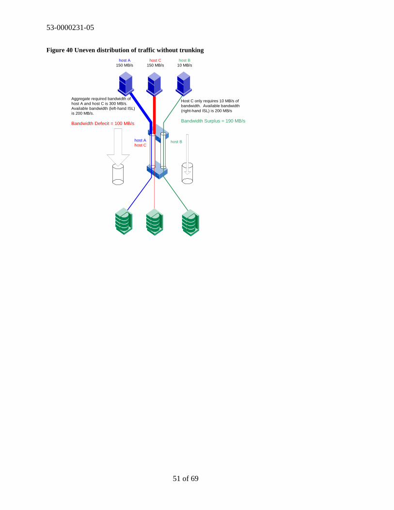
53-0000231-05
51 of 69
Figure 40 Uneven distribution of traffic without trunking
host A150 MB/s
host C150 MB/s
host B10 MB/s
host Ahost C
host B
Aggregate required bandwidth ofhost A and host C is 300 MB/s.Available bandwidth (left-hand ISL)is 200 MB/s.
Bandwidth Defecit = 100 MB/s
Host C only requires 10 MB/s ofbandwidth. Available bandwidth(right-hand ISL) is 200 MB/s
Bandwidth Surplus = 190 MB/s

53-0000231-05
52 of 69
Figure 41 depicts a similar scenario as shown in the Figure 40 configuration. Notice that allvariables are the same, except that trunking is utilized. The trunk is a logical aggregation of thetwo 200 MB/sec ISLs into one logical 400 MB/sec trunk. Note that trunking allows the groupingof up to four 2 Gbit/sec ISLs into one logical 8 Gbit/sec trunk. The trunk provides sufficientbandwidth for all traffic streams.
Figure 41 Performance and management benefits of trunking
h o s t A1 5 0 M B / s
h o s t C1 5 0 M B / s
h o s t B1 0 M B /s
A g g r e g a te r e q u i r e d b a n d w id th o f h o s t A , h o s t B , & h o s t Cis 3 1 0 M B / s . A v a i l a b le b a n d w id th i s 4 0 0 M B /s .
B a n d w id t h S u r p lu s = 9 0 M B / s
h o s t Ah o s t Bh o s t C
h o s t Ah o s t Ch o s t B
2 IS L T r u n k = 4 0 0 M B /s
How Does Trunking Impact SAN Design?Trunking optimizes the utilization of ISLs and reduces the SAN administration effort. Thesebenefits enhance the utility of ISLs and so enhance the utility of designs that make use of ISLs.Given two SANs of equivalent functionality, the SAN that is easier to manage has the advantage.Instead of monitoring multiple ISLs, a single trunk is now monitored. The high performancecapabilities of a trunking capable switch make these types of switches ideal for placement in thecore of a core/edge fabric. Because the trunk is efficient, it is less likely that congestion will beexperienced and it is possible that fewer ISL are required in the fabric topology, yieldingadditional ports for attaching SAN devices.
When designing a SAN with trunking capable switches or introducing trunking capable switchesto an existing SAN, it is important to place these switches adjacent to each other when workingwith Mesh, Ring, or Cascade topologies.
When working with a core/edge topology, it is recommended to place the SilkWorm 3000 seriesswitches in the core. As new trunking capable switches are added to a core/edge topology, it will

53-0000231-05
53 of 69
allow the added switches to connect with trunking capable switches. Migrating existingSilkWorm 2000 series switches from the core to the edge and inserting trunking capable switchesinto the core is an effective strategy.
The ISLs that comprise a trunk must all reside in the same contiguous four-port groups, whichare termed quads. For example, on the SilkWorm 3800, the following ports are grouped intoquads: 0-3, 4-7, 8-11, and 12-15. Therefore, when connecting two switches in a fabric with one,two or three ISLs, consider leaving open the other ports on the quad for future trunk growth.
How 2 Gbit/sec Switches Impact a SAN DesignA switch that supports auto-sensing of both 1 Gbit/sec and 2 Gbit/sec device connections, suchas the SilkWorm 3800 or SilkWorm 12000, introduces many benefits and choices to the SANdesigner. As SAN devices evolve from 1 Gbit/sec to 2 Gbit/sec capable, the role of a 2 Gbit/secswitch becomes very important for connecting SAN devices. Designing in such a capability“future-proofs” a SAN and extends the life span of the initial design. As an interconnect betweenswitches, 2 Gbit/sec ISLs deliver high performance. Devices that are not 2 Gbit/sec capable canstill benefit from a switch’s 2 Gbit/sec capabilities, as it is possible to combine multiple 1Gbit/sec connections over a 2 Gbit/sec ISL or trunk. Many 1 Gbit/sec devices today barely utilizethe full bandwidth of a 1 Gbit/sec connection. This should not be a surprise and is why it ispossible to design a SAN with over-subscription. The advent of 2 Gbit/sec ISLs essentiallydoubles the performance of a similarly designed SAN built with 1 Gbit/sec ISLs and nodes. Thismeans that twice the performance is available, if required, or it is possible to scale back thenumber of ISLs to yield additional ports for device connections. Trunking amplifies thisperformance benefit, as the ISLs are now faster and used more efficiently.
2 Gbit/sec Switch PlacementWhen designing a SAN with 2 Gbit/sec switches, the same guidelines that apply to trunkingapply to 2 Gbit/sec capabilities. Place these switches adjacent to each other to take advantage of2 Gbit/sec ISLs. Of course, it is also possible to connect a SilkWorm 2000 series switch to atrunking capable switch, as Brocade trunking capable switches are backwards compatible andwill negotiate a 1 Gbit/sec ISL.
For core/edge topologies, place trunking capable switches in the core. If 2 Gbit/sec connectivityis required, it is acceptable to attach these devices to the 2 Gbit/sec cores if 2 Gbit/sec edgeswitches are not yet implemented. By placing 2 Gbit/sec switches in the core, it ensures that a 2Gbit/sec path exists end to end. If a significant number of 2 Gbit/sec devices are required and theperformance requirements are high, an effective strategy is to localize the 2 Gbit/sec devices onthe same switch or group of switches. Figure 42 depicts 2 Gbit/sec devices with and without 2Gbit/sec end-to-end paths as well as the localization of some 2 Gbit/sec devices.
(Note: This example is presented to establish the benefits of placing a trunking capable switch inthe core and the issues that can arise by keeping a SilkWorm 2000 series switch in the core. Thisexample is a poor design by choice and is not something that a designer should implement unlessthere are compelling reasons to do so.)

53-0000231-05
54 of 69
Figure 42. End to end 2 Gbit/sec path and 2 Gbit/sec device locality
1 Gb/s ISL2 Gb/s connect4 Gb/s Trunk
3800
3800
3800
38003800
2800 2800
2800
Localize 2 Gb/sdevices
No
t2
Gb
/sE
nd
toen
d
2G
b/s
En
dto
end
More Ports or Higher Performance?With 2 Gbit/sec switches, the designer has a choice: more ports or higher performance. In Figure43, two 224-port core/edge topologies are shown. Note that with the same number of switchesand ISLs, the SilkWorm 3800 based topology delivers better performance, with an ISLsubscription ratio of 3.5:1 as compared to 7:1 with a SilkWorm 2800 based fabric.
Figure 43. With the same number of switches and ISLs, the SilkWorm 3800 based topology delivers betterperformance.
18 switch resilient star = 224ports @ 7 to 1 ISLoversubsciption ratio
Assumes all 1 GB Edgedevices18 switch resilient star = 224ports @ 3.5:1 ISLoversubscription ratio
38002x00
An alternative is to utilize fewer ISLs in a topology to yield similar performance and moredevice ports. A core/edge topology with six switches is shown in Figure 44. The top topology isdesigned with two ISLs from each edge switch to each core switch and yields 64-ports with a 3:1ISL subscription ratio. The bottom topology is designed with one ISL from each edge switch toeach core switch and yields 80-ports with a 3.5-to 1-ISL subscription ratio.

53-0000231-05
55 of 69
Figure 44. With the same number of switches and fewer ISLs, the SilkWorm 3800 based topology deliverssimilar performance and a higher port count than a SilkWorm 2800 based topology
38002x00
64 ports3 to 1 ISL over subscription
80 portsAssumes all 1 GB Edge devices3.5 to 1 ISL over subscription
Cabling For High AvailabilityWhen cabling SAN, be careful that a power outage does not take down the entire fabric or SAN.This means placing each fabric of a redundant fabric on different power circuits or cabling singlefabrics in such a way that the fabric can remain functional if a power circuit fails, as shown inFigure 45.
Figure 45. Cabling A SAN for Availability
Rack B,Circuit B
SAN A SAN B
Hosts
Storage
Rack A,Circuit A
Seperate Circuits

53-0000231-05
56 of 69
SilkWorm 12000 Device Attachment StrategiesYou must take availability, scalability, and performance into account when attaching devices tothe SilkWorm 12000. Due to the high port density characteristics of the SilkWorm 12000, it isfrequently easy to localize devices that communicate with each other onto the same switch.Localizing traffic enhances performance, as fewer ISLs are utilized and higher scalability sincemore ports are available for nodes.
Attaching Nodes for AvailabilityTo maximize availability, distribute devices and ISLs across cards. This will minimize theimpact to the SAN in the unlikely event of a 16-port card failure. To effectively distribute theconnections, it is important to understand the connection types and relationships. For example, alarge storage array may have sixteen ports. If these connections were evenly distributed acrossthe cards of a SilkWorm 12000 switch, the failure of a 16-port card would only affect a few ofthe array ports. Similarly, when connecting devices by type (i.e. host, storage), distribute theseconnections across the SilkWorm 12000 16-port cards. Figure 46 depicts the attaching of devicesacross 16-port cards for availability. While it is not necessary to attach devices in groups, asshown, it does make it easier to manage the device connections.
Note: Distribute devices across 16-port cards from left to right for optimal availability; not fromtop to bottom.
Figure 46. Attaching devices to a 16-port card
Distribute High Port Count Devices,Such as Arrays or Tape Libraries AcrossMultiple Blades
Distribute Devices & ISLs Across Blades
StorageTape
Hosts
ISLs
StorageTape
Hosts
ISLs

53-0000231-05
57 of 69
SilkWorm 12000 Availability ConsiderationsThe dual switch – single chassis implementation of the SilkWorm 12000 ideally suits this switchfor the role of a core switch. Recall that for a resilient core/edge fabric, two is the minimumnumber of core switches. The SilkWorm 12000 is a single chassis that houses two logicalswitches. The two logical switches are powered by an active Control Processor (CP) with afailover of both switches to the standby CP card occurring should the active CP card fail. Duringthe failover, there is a brief disruption of I/O for both switches. Additionally, any environmentalproblem or operator error that could take out the whole chassis would then disrupt both fabricssimultaneously. For this reason we recommend one fabric per chassis. This means eitherconnecting the two logical switches together or to other switches in the same fabric. Somedesigners may opt for a two chassis core for optimal availability and performance.
Note: For the highest availability and to avoid any environmental problem that could take out the wholechassis, consider using two chassis’ for the core of a core/edge fabric also, it is suggested to only use onefabric per chassis to mitigate environmental problems that could take out the whole chassis.
Figure 47. Use Two SilkWorm 12000 Chassis For The Highest Availability
38003800 3800380038003800

53-0000231-05
58 of 69
Section 5: Testing and Fabric Support Levels
Brocade is currently testing and validating fabrics consisting of hundreds of ports and has plansfor testing multi-thousand port fabrics. The ultimate limitation in fabric design today and asdefined in the Fibre Channel standards is a maximum of 239 physical switches, be they 8, 16, or64 port versions. As a practical matter, no vendor has yet tested networks of this size due to theexpense and complexity of implementing such a network. The current practical switch-countlimit is lower than 239 switches, based upon empirical testing. Another limit on SAN design isthe hop count and ISLs.
Brocade partners with many OEMs and resellers who supply switches to end-users. Many ofthese partners provide direct support for the switches they sell. These partners extensively testand support specific configurations, including switches, storage, HBAs, and other SANcomponents. In some cases, the large fabric configurations supported by Brocade partners willdiffer from the guidelines Brocade presents in this document. In fact, several Brocade switchpartners have developed their own SAN design guidelines, including in-depth support matrixesthat specify support configurations and firmware versions.
Those partners who do not provide direct switch support sell their customers Brocade ServicePlans with the switches and these customers obtain their support from Brocade. For moreinformation on support for SilkWorm switches, you can contact your switch provider. For moreinformation on Brocade Service Plans, visit www.brocade.com.
To determine whether a SAN is supported, it is necessary to work with your support provider todetermine if you SAN design is valid. Important variables that determine the supportability of aparticular SAN are the number of switches, version of Fabric OS, the topology, number of ISLs,number of free ports, and the hop count.

53-0000231-05
59 of 69
Section 6: Reference Topologies
It is always beneficial to learn from others’ experience. In addition to extensive internal testingprograms, and leveraging testing done by partners, Brocade has made a serious effort to learnfrom end users what they have built, and how it has worked for them. This section contains someexamples of networks that are successfully deployed by many end users. These designs are alsoextensively tested by Brocade. The foundation topology for the reference topologies that followis the core/edge topology. Other topologies can and do work very well. If the requirements arescalability, availability, and performance, it is probable that these reference topologies will workfor you. As discussed throughout this document, it is possible to tune the core/edge topology forperformance and size by adding edge switches, core switches, or ISLs. For the best availability,it is recommended to design a dual fabric SAN, which can be accomplished by deploying anytwo of the reference topologies, as shown in Figure 48.
Figure 48. Dual, Resilient 96-Port Fabrics
Storage
Hosts
If you have an estimate of your port count and performance requirements, you can pick one ofthe following designs and “be done with it”. You do not have to build the entire design at once.You can build towards the target design, and “pay as you grow.”
Note that two ISL over subscription ratios are provided in the reference topologies tables since itis necessary to account for 2 Gbit/sec capable switches. The ISL subscription ratios do notchange if all devices and ISLs are the same speed. However, if the edge devices are all 1 Gbit/secand the ISLs are 2 Gbit/sec, the ratios do change. If your mix of devices is different, you cancalculate the ISL over-subscription ratio as detailed in ISL Over-Subscription on page 26.

53-0000231-05
60 of 69
The reference topologies are presented in three sections: topologies built using only 16-portswitches, topologies built using a mixture of 16-port and 64-port switches, and topologies builtusing only 64-port switches. They are presented this way because typically the designs areconceived that way. E.g. a user who already has a set of 16-port switches will not need to referto designs which only use 64-port switches, whereas an enterprise customer who is deploying a“green field” SAN and wants maximal scalability usually will only look at 64-port switches.
16-Port Switch Designs
56-Port FabricThis is an effective small fabric. It looks similar to a mesh topology. If you plan to grow thisfabric, device placement becomes important. Instead of filling up all switches with devices, startadding new switches to the core switches to enable growth. In the fashion, it is possible to growthe fabric to 224-ports, because it becomes a “starter core/edge fabric.” If the fabric is targeted tostart small and stay below 56-ports, it is acceptable to fill the empty core ports with edge devices.The performance characteristics will differ from a core/edge topology under this scenario due todevice placement on the core switches (see Section 2, Device Attachment Strategies) and it maybe necessary to employ some level of locality or to insert additional ISLs.
Figure 49. 56-port Core/Edge Fabric
Identification 2 edge by 2 core by 1 ISL (2e x 2c x 1i)
Edge ports 56
Switch count 4
ISL over-subscription
Same Speed Edge Devices and ISLs 1 Gb Edge Devices / 2 Gb ISLs
7 to 1 3.5 to 1

53-0000231-05
61 of 69
96-Port FabricThis fabric is effective if 96 high performance ports are required. To scale this fabric it isnecessary to migrate the core switches to the edge and utilize higher port count core switches tofill in the vacancies. Alternatively, if a high performance, high port count fabric is required; itmay be more appropriate to use four switches in the core (see 160-Port Fabric referencetopology), with a single ISL connecting each Edge switch to each core switch. Notice that thehigh performance is enabled by the use of two ISLs between each Edge switch and each coreswitch. It is not necessary to utilize two ISLS between the edges and cores if the performance isnot required. If single ISLs are utilized between Edge and core, it creates a fabric that yields 128-ports.
Figure 50. 96-port Core/Edge Fabric
Identification 8 edge by 2 core by 2 ISLs (8e x 2c x 2i)
Edge ports 96
Switch count 10
ISL over-subscription
Same Speed Edge Devices and ISLs 1 Gb Edge Devices / 2 Gb ISLs3 to 1 1.5 to 1

53-0000231-05
62 of 69
160-Port FabricThis mid-sized fabric is capable of scaling to 192 ports by adding Edge switches and even largerwith higher port count core switches. Note that four switches are utilized in the core to deliverhigh performance and enable scalability and it is possible to build a similar topology with onlytwo core switches. This topology provides the same performance as the 96-port referencetopology.
Figure 51. 160-port Core/Edge Fabric
\
Identification 16 edge by 4 core by 1 ISL (12e x 4c x 1i)
Edge ports 160
Switch count 16
ISL over-subscription
Same Speed Edge Devices and ISLs 1 Gb Edge Devices / 2 Gb ISLs3 to 1 1.5 to 1
224-Port FabricThis is the largest simple core/edge topology possible using 16-port switches. If a larger SAN isrequired, use larger core switches or build a Hybrid topology.
Figure 52. 224-port Core/Edge Fabric
Identification 16 edge by 2 core by 1 ISL (16e x 2c x 1i)
Edge ports 224
Switch count 18
ISL over-subscription
Same Speed Edge Devices and ISLs 1 Gb Edge Devices / 2 Gb ISLs7 to 1 3.5 to 1
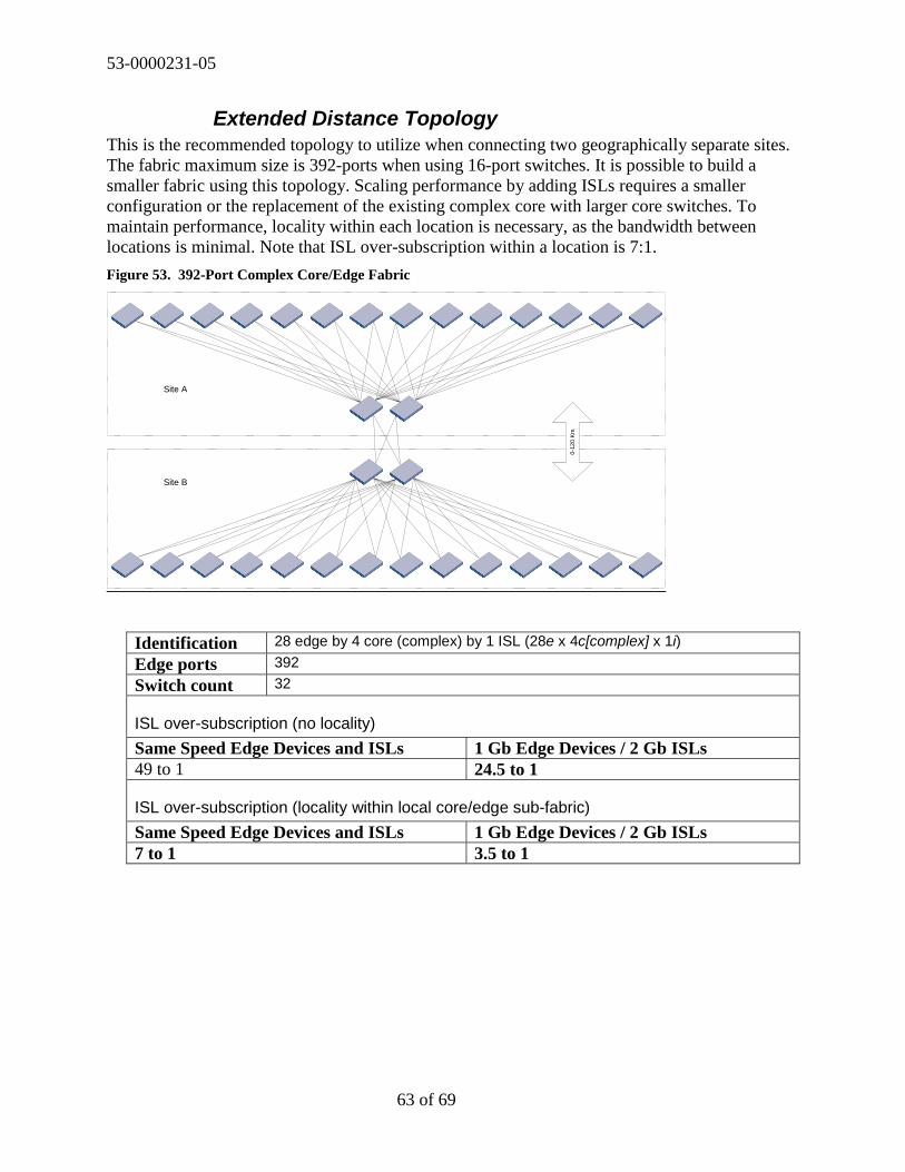
53-0000231-05
63 of 69
Extended Distance TopologyThis is the recommended topology to utilize when connecting two geographically separate sites.The fabric maximum size is 392-ports when using 16-port switches. It is possible to build asmaller fabric using this topology. Scaling performance by adding ISLs requires a smallerconfiguration or the replacement of the existing complex core with larger core switches. Tomaintain performance, locality within each location is necessary, as the bandwidth betweenlocations is minimal. Note that ISL over-subscription within a location is 7:1.
Figure 53. 392-Port Complex Core/Edge Fabric
0-12
0K
m
Site A
Site B
Identification 28 edge by 4 core (complex) by 1 ISL (28e x 4c[complex] x 1i)
Edge ports 392
Switch count 32
ISL over-subscription (no locality)
Same Speed Edge Devices and ISLs 1 Gb Edge Devices / 2 Gb ISLs49 to 1 24.5 to 1
ISL over-subscription (locality within local core/edge sub-fabric)
Same Speed Edge Devices and ISLs 1 Gb Edge Devices / 2 Gb ISLs7 to 1 3.5 to 1
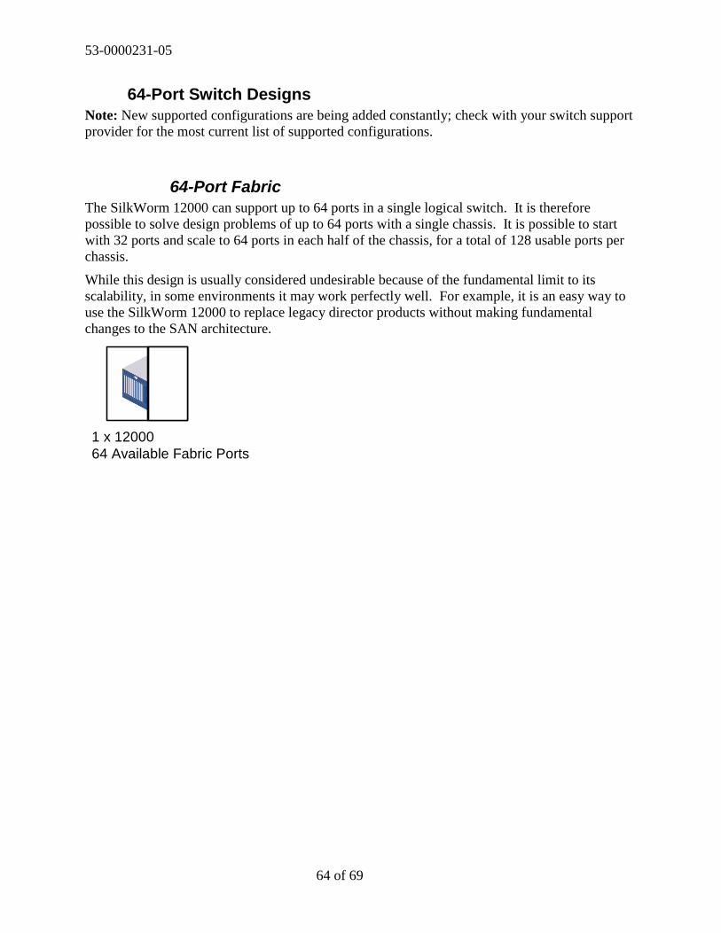
53-0000231-05
64 of 69
64-Port Switch DesignsNote: New supported configurations are being added constantly; check with your switch supportprovider for the most current list of supported configurations.
64-Port FabricThe SilkWorm 12000 can support up to 64 ports in a single logical switch. It is thereforepossible to solve design problems of up to 64 ports with a single chassis. It is possible to startwith 32 ports and scale to 64 ports in each half of the chassis, for a total of 128 usable ports perchassis.
While this design is usually considered undesirable because of the fundamental limit to itsscalability, in some environments it may work perfectly well. For example, it is an easy way touse the SilkWorm 12000 to replace legacy director products without making fundamentalchanges to the SAN architecture.
1 x 1200064 Available Fabric Ports

53-0000231-05
65 of 69
124-Port FabricThe two logical switches in a chassis can be connected to form one fabric. A minimum of twoISLs should be used to ensure high availability. In this configuration, the fabric would have 124available ports. If greater performance between the switches is desired, more ISLs can be added.A reasonable design target might be to start with a 7:1 over-subscription ratio on the ISLs. Inthis scenario, each blade in the SilkWorm 12000 would have two ISLs. This would result in afabric with 112 free ports. For the most performance-critical applications, a ratio of 3:1 could betargeted. Each blade would have four ISLs in that scenario, and the total free port count wouldbe 96 in the fabric.
Identification 2 64-port switch cascade with 4 to 16 ISLs
Edge ports 96 to 124
Switch count 2
ISL over-subscription
Same Speed Edge Devices and ISLs 1 Gb Edge Devices / 2 Gb ISLs
7 to 1, using 8 ISLs 3.5 to 1, using 8 ISLs
2 x 12000up to 124 Available Fabric Ports
1-4
1-4
1-4
1-4

53-0000231-05
66 of 69
248-Port FabricThe same principal used in the 124-port fabric (above) can be extended to interconnect twochassis. Using one ISL per blade on just two blades per switch, the resulting fabric has 248available ports. Targeting a 7:1 over-subscription ratio with two ISLs per blade one each blade,the number of ports in the fabric is 224. Targeting a 3:1 over-subscription ratio by using fourISLs per blade, the port count is 192 in the fabric.
4 x 12000up to 240 Available Fabric Ports
1-41-4
1-41-4
Identification 2 64-port edge by 2 64-port core by 4 to 8 ISLs
Edge ports 192 to 248
Switch count 4
ISL over-subscription
Same Speed Edge Devices and ISLs 1 Gb Edge Devices / 2 Gb ISLs
7 to 1, using 8 ISLs 3.5 to 1, using 8 ISLs

53-0000231-05
67 of 69
368-Port FabricThe 248-port design above can be further extended to three chassis, or six 64-port logicalswitches. If this is done, the total available port can be as high as 368 ports. Targeting a 7:1over-subscription ratio, the free port count is 320. Targeting a 3:1 over-subscription ratio byusing four ISLs per blade, the port count is 256 in the fabric.
Identification 4 64-port edge by 2 64-port core by 4 to 8 ISLs
Edge ports 256 to 368
Switch count 6
ISL over-subscription
Same Speed Edge Devices and ISLs 1 Gb Edge Devices / 2 Gb ISLs
7 to 1, using 8 ISLs 3.5 to 1, using 8 ISLs

53-0000231-05
68 of 69
16- and 64-Port Switch Mixed DesignsNote: New supported configurations are being added constantly; check with your switch supportprovider for the most current list of supported configurations.
440-Port and 512-Port FabricsIt is possible to use a SilkWorm 12000 as a core, and use 16-port switches at the edge.Currently, the total number of supported edge switches is 26. This number is increasing astesting progresses. Using 7:1 as an over-subscription target, it is possible to design a networkwith 440 available ports. Up to two of the edge switches could be SilkWorm 12000 logicalswitches. The network could then scale to up to 512 available ports
[...] [...]
Identification 2 64-port edge plus 24 16-port edge by 2 64-port core by 2-8 ISLs
Edge ports 512
Switch count 28
ISL over-subscription
Same Speed Edge Devices and ISLs 1 Gb Edge Devices / 2 Gb ISLs
7 to 1 3.5 to 1

53-0000231-05
69 of 69
Copyright
IMPORTANT NOTICE
This document is the property of Brocade. It is intended solely as an aid for installing andconfiguring Storage Area Networks constructed with Brocade switches. This document does notprovide a warranty to any Brocade software, equipment, or service, nor does it imply productavailability. Brocade is not responsible for the use of this document and does not guarantee theresults of its use. Brocade does not warrant or guarantee that anyone will be able to recreate orachieve the results described in this document. The installation and configuration described inthis document made use of third party software and hardware. Brocade does not make anywarranties or guarantees concerning such third party software and hardware.
© 2002, Brocade Communications Systems, Incorporated.
ALL RIGHTS RESERVED. Part number: 53-0000231-05
BROCADE, SilkWorm, SilkWorm Express, and the BROCADE logo are trademarks orregistered trademarks of Brocade Communications Systems, Inc., in the United States and/or inother countries.
All other brands, products, or service names are or may be trademarks or service marks of, andare used to identify, products or services of their respective owners.
NOTICE: THIS DOCUMENT IS FOR INFORMATIONAL PURPOSES ONLY AND DOES NOT SETFORTH ANY WARRANTY, EXPRESS OR IMPLIED, CONCERNING ANY EQUIPMENT, EQUIPMENTFEATURE, OR SERVICE OFFERED OR TO BE OFFERED BY BROCADE. BROCADE RESERVES THERIGHT TO MAKE CHANGES TO THIS DOCUMENT AT ANY TIME, WITHOUT NOTICE, ANDASSUMES NO RESPONSIBILITY FOR ITS USE. THIS INFORMATIONAL DOCUMENT DESCRIBESFEATURES THAT MAY NOT BE CURRENTLY AVAILABLE. CONTACT A BROCADE SALES OFFICEFOR INFORMATION ON FEATURE AND PRODUCT AVAILABILITY.
Export of technical data contained in this document may require an export license from theUnited States Government.
Brocade Communications Systems, Incorporated1745 Technology DriveSan Jose, CA 95110
Recommended