BF20 belt drive kit installation instructions.
Thank you for purchasing the BenchTopPrecision BF20 belt-drive kit. The following in-structions will walk you through step by step to install the belt drive properly. This kit was designed to work on all variations of the BF20 mill. As with most Chinese made benchtop mills, they are handled by many different distributors and all have there slight differences . Through much testing from various beta testers, we’ve developed a kit that installs easy and preforms flawlessly. It offers a significant increase in overall speed while maintaining a two speed drive. Some other important features are noise reducton, no more broken gears, and the ability to still use the quill function.
Copyright© 2014 BenchTopPrecision.comWarning: No portion of this manual may be reproduced of any shape or form with out writ-ten approval of BenchTopPrecision.com
10/26/14

!!WARNING!!This manual provides critical information of the installation procedure for the product described. Failure to read, understand, and follow the instructions given in the manual can result in serious personal injury or property damage. The owner of this equipment is solely responsible for its safe use. The manufacturer will not be held liable for personal injury or property damage for negligence, improper installation, modifications, or misuse.
With that being said, lets get started.
1.
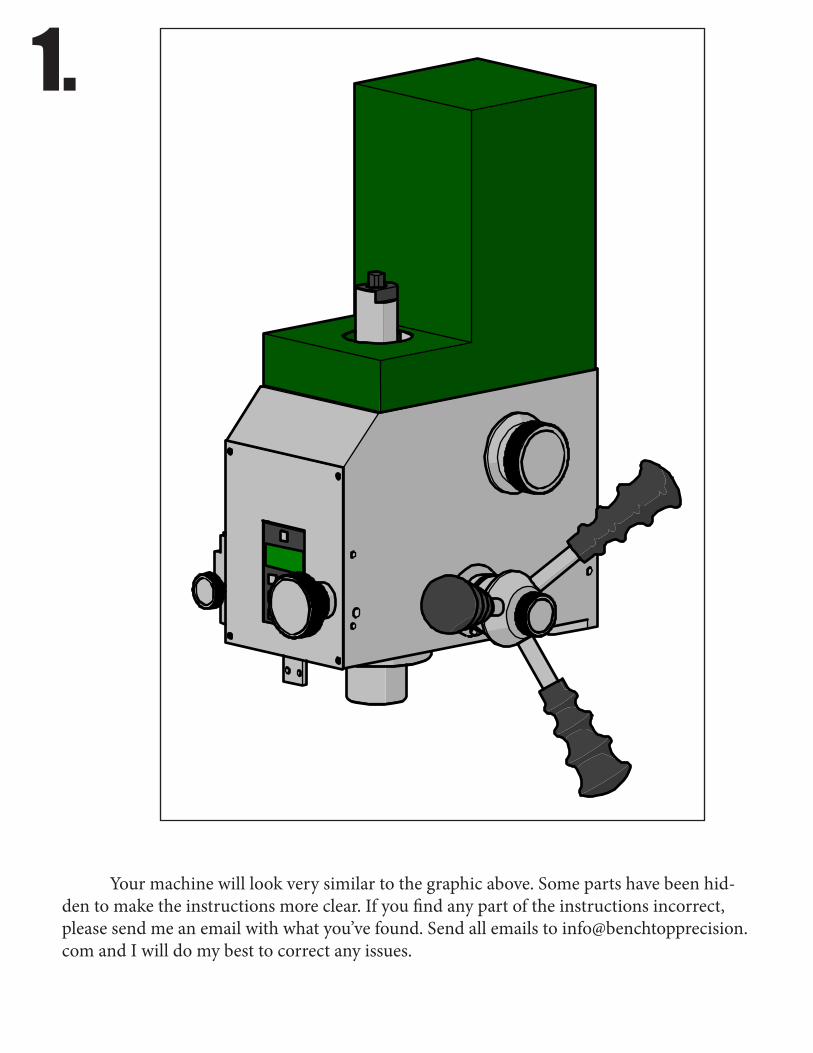
Your machine will look very similar to the graphic above. Some parts have been hid-den to make the instructions more clear. If you find any part of the instructions incorrect, please send me an email with what you’ve found. Send all emails to [email protected] and I will do my best to correct any issues.

2.
Start off by removing the motor cover as shown.

3.
Remove the six M6 socket head cap screws so that the motor and mount can be removed as one assembly. Depending on your machine you may have to disconnect the motor power wires. Be sure the machine is unplugged before doing so to prevent injury.
4.
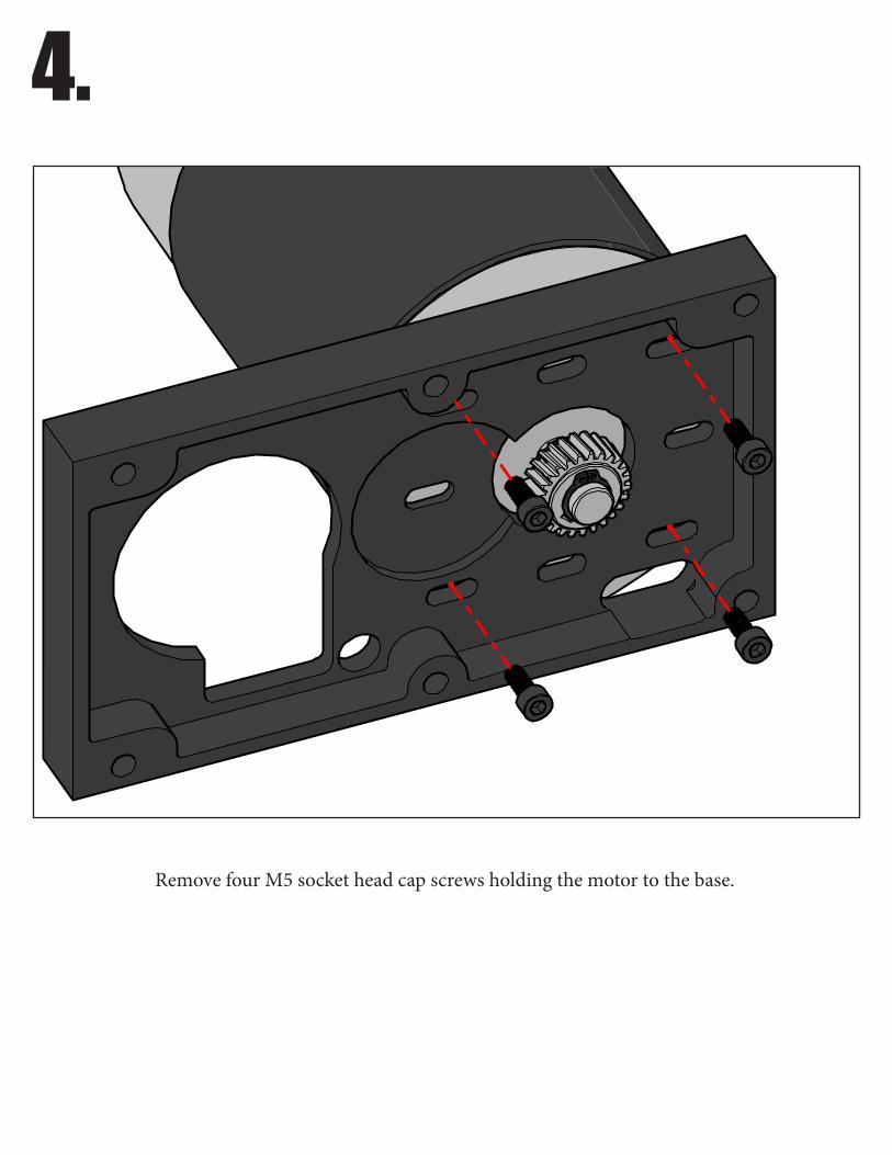
Remove four M5 socket head cap screws holding the motor to the base.
5.
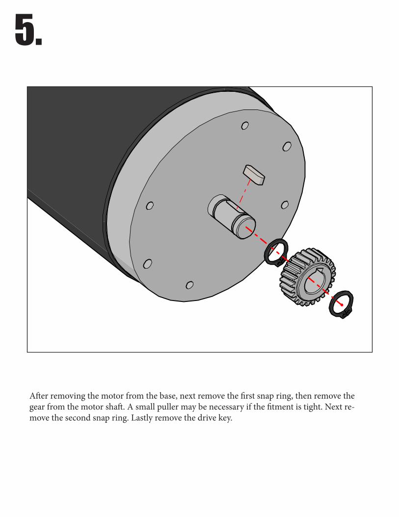
After removing the motor from the base, next remove the first snap ring, then remove the gear from the motor shaft. A small puller may be necessary if the fitment is tight. Next re-move the second snap ring. Lastly remove the drive key.
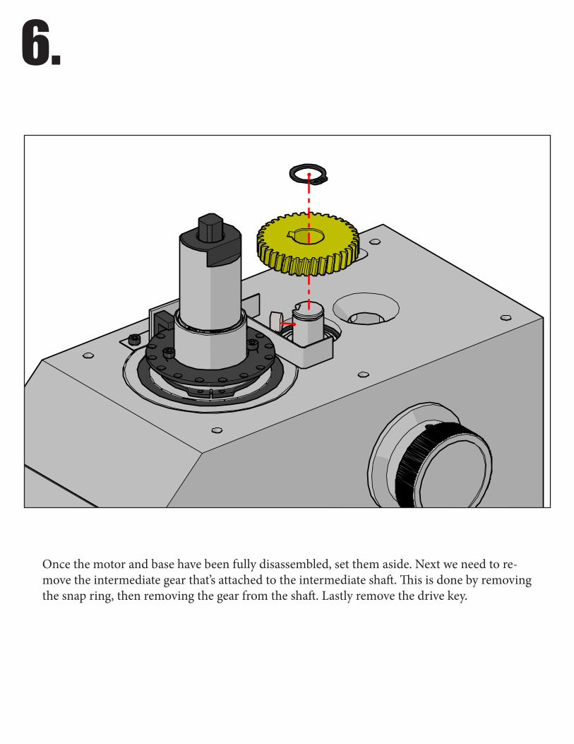
6.
Once the motor and base have been fully disassembled, set them aside. Next we need to re-move the intermediate gear that’s attached to the intermediate shaft. This is done by removing the snap ring, then removing the gear from the shaft. Lastly remove the drive key.
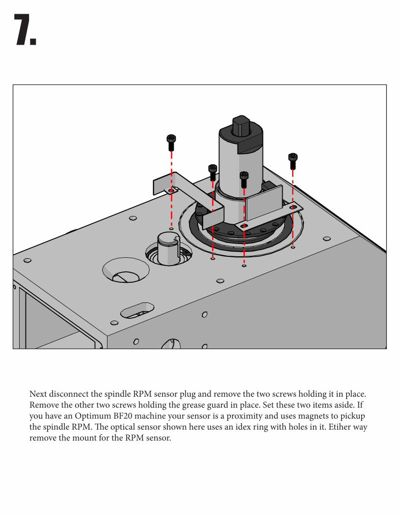
7.
Next disconnect the spindle RPM sensor plug and remove the two screws holding it in place. Remove the other two screws holding the grease guard in place. Set these two items aside. If you have an Optimum BF20 machine your sensor is a proximity and uses magnets to pickup the spindle RPM. The optical sensor shown here uses an idex ring with holes in it. Etiher way remove the mount for the RPM sensor.
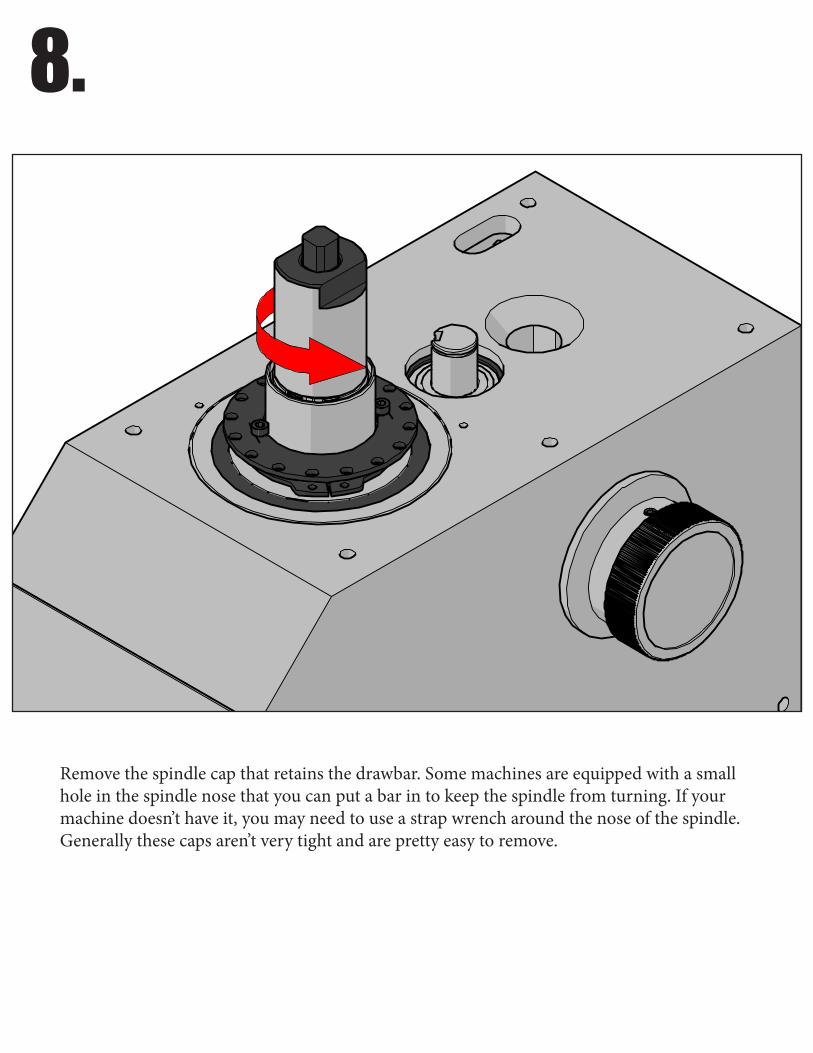
8.
Remove the spindle cap that retains the drawbar. Some machines are equipped with a small hole in the spindle nose that you can put a bar in to keep the spindle from turning. If your machine doesn’t have it, you may need to use a strap wrench around the nose of the spindle. Generally these caps aren’t very tight and are pretty easy to remove.

9.
Remove drawbar.
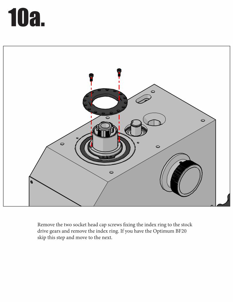
10a.
Remove the two socket head cap screws fixing the index ring to the stock drive gears and remove the index ring. If you have the Optimum BF20 skip this step and move to the next.
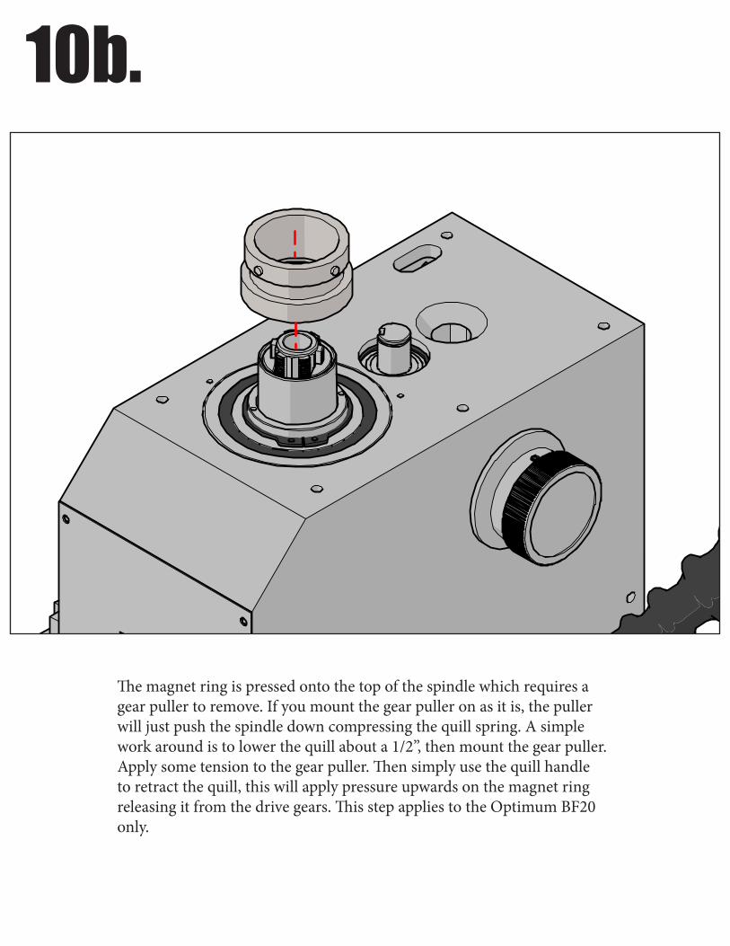
10b.
The magnet ring is pressed onto the top of the spindle which requires a gear puller to remove. If you mount the gear puller on as it is, the puller will just push the spindle down compressing the quill spring. A simple work around is to lower the quill about a 1/2”, then mount the gear puller. Apply some tension to the gear puller. Then simply use the quill handle to retract the quill, this will apply pressure upwards on the magnet ring releasing it from the drive gears. This step applies to the Optimum BF20 only.
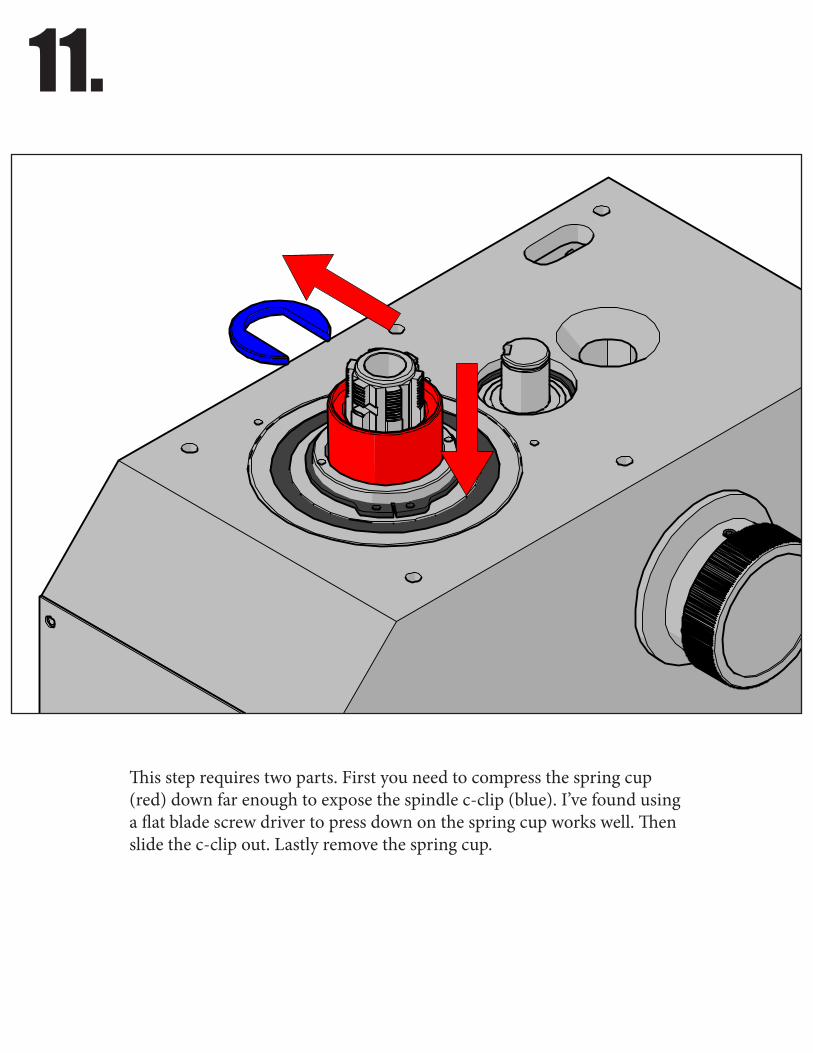
11.
This step requires two parts. First you need to compress the spring cup (red) down far enough to expose the spindle c-clip (blue). I’ve found using a flat blade screw driver to press down on the spring cup works well. Then slide the c-clip out. Lastly remove the spring cup.

12.
Remove quill spring.
13.
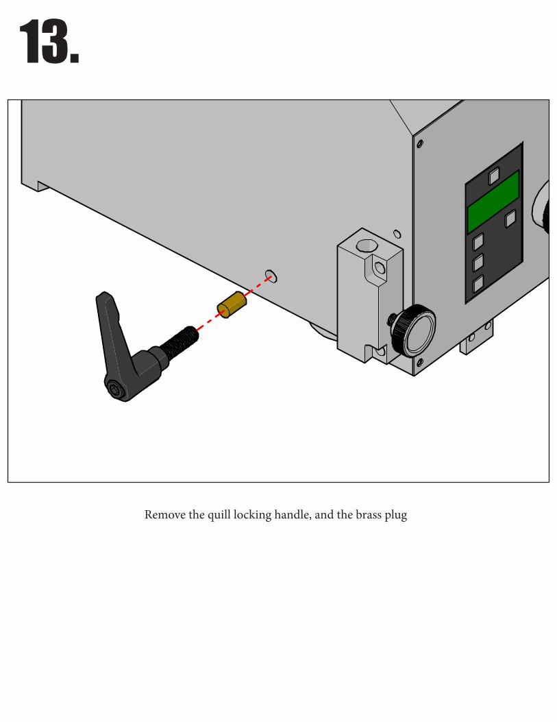
Remove the quill locking handle, and the brass plug
14.
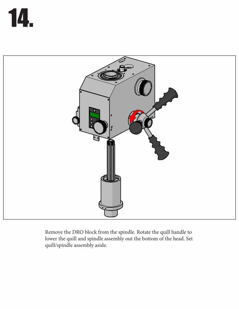
Remove the DRO block from the spindle. Rotate the quill handle to lower the quill and spindle assembly out the bottom of the head. Set quill/spindle assembly aside.
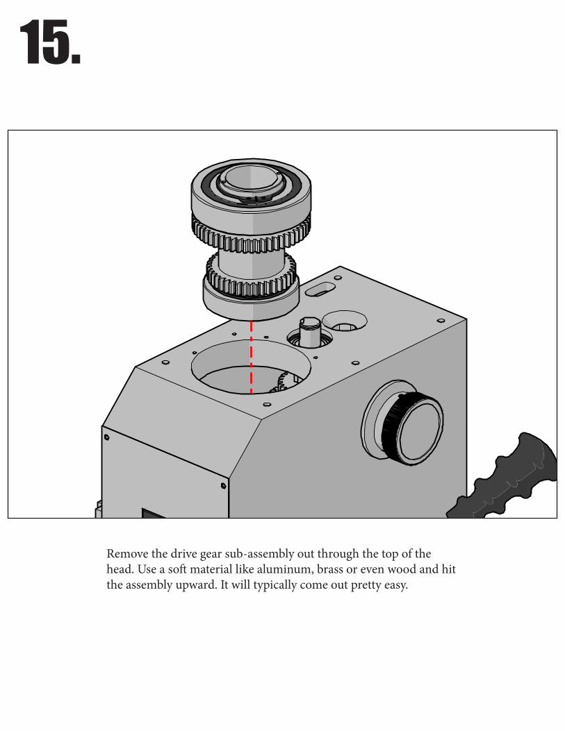
15.
Remove the drive gear sub-assembly out through the top of the head. Use a soft material like aluminum, brass or even wood and hit the assembly upward. It will typically come out pretty easy.

16.
If you purchased the bearing kit with your belt drive kit, you can skip this step and move onto the next. If you decided to re-use the exisiting bearings, then you need to remove them from the stock drive gears to be re-pressed on the new bearing carrier that is supplied with the belt drive kit. This is probably the hardest part of the disassembly as the bearings are known to be quite difficult to remove at times. The easiest way, is to use a gear puller. Be careful not to damage the bearings.
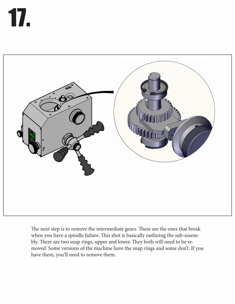
17.
The next step is to remove the intermediate gears. These are the ones that break when you have a spindle failure. This shot is basically outlining the sub-assem-bly. There are two snap rings, upper and lower. They both will need to be re-moved. Some versions of the machine have the snap rings and some don’t. If you have them, you’ll need to remove them.
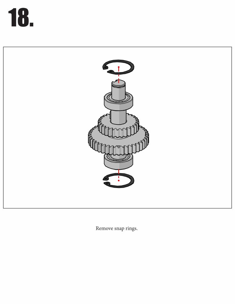
18.
Remove snap rings.
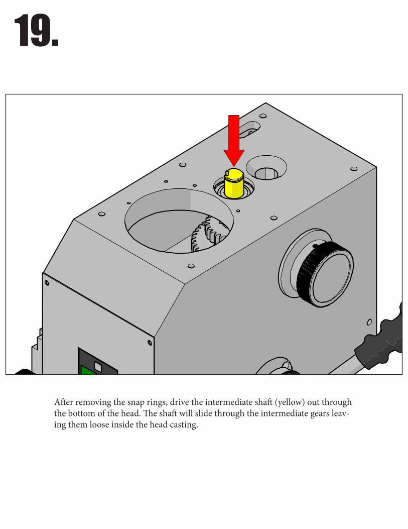
19.
After removing the snap rings, drive the intermediate shaft (yellow) out through the bottom of the head. The shaft will slide through the intermediate gears leav-ing them loose inside the head casting.
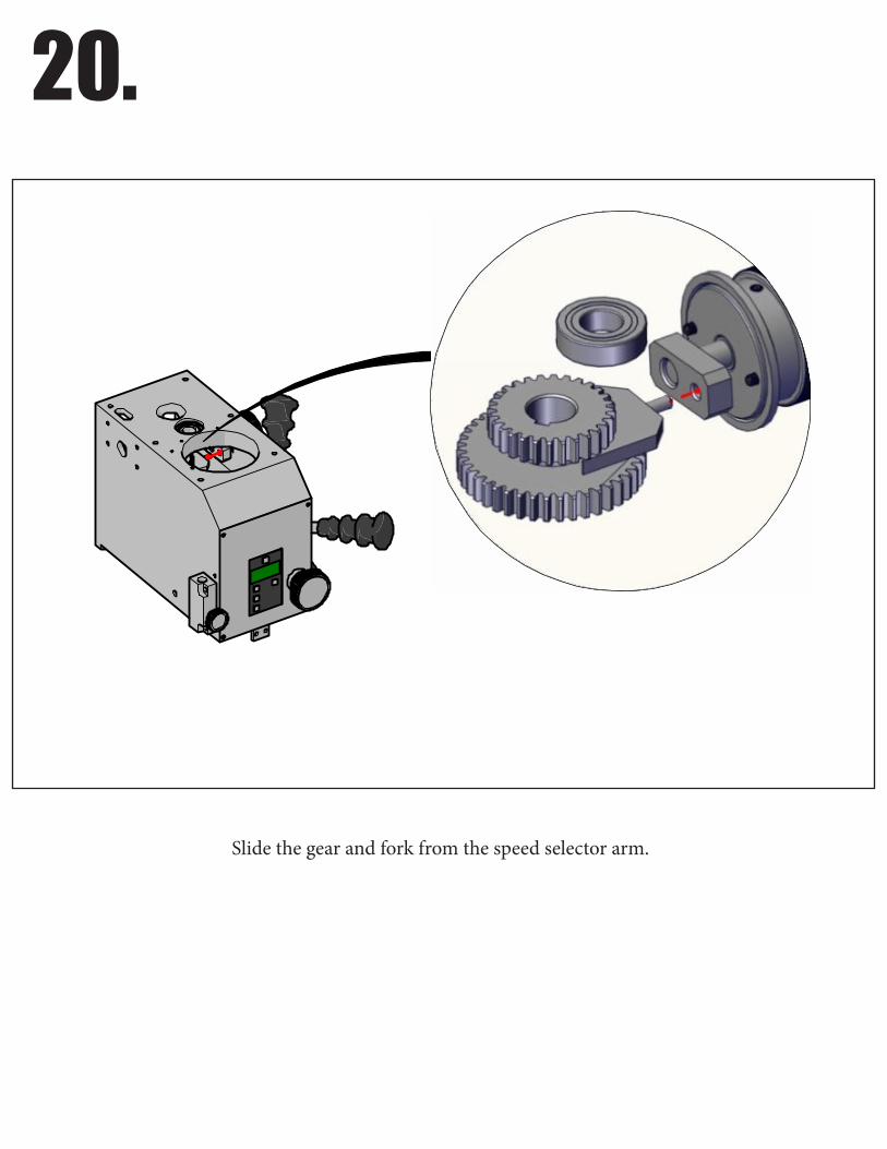
20.
Slide the gear and fork from the speed selector arm.

21.
Remove intermediate gears and selector fork through the top of the head as shown.
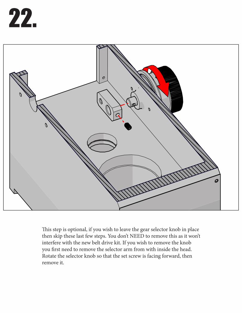
22.
This step is optional, if you wish to leave the gear selector knob in place then skip these last few steps. You don’t NEED to remove this as it won’t interfere with the new belt drive kit. If you wish to remove the knob you first need to remove the selector arm from with inside the head. Rotate the selector knob so that the set screw is facing forward, then remove it.
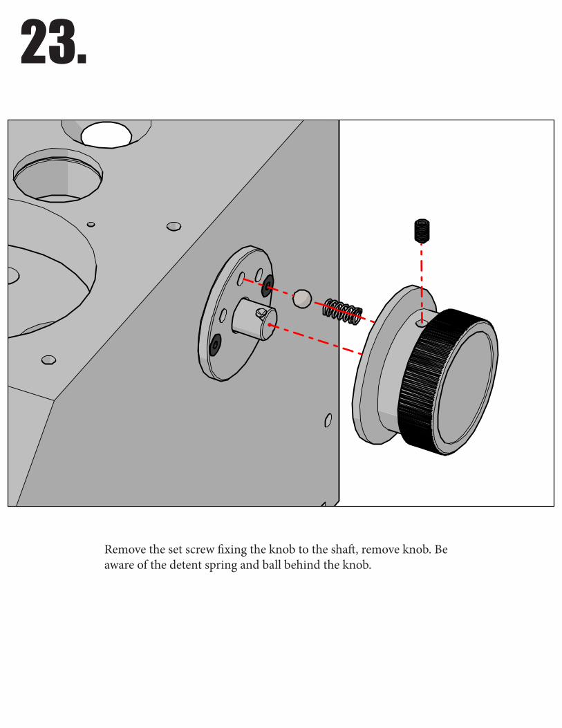
23.
Remove the set screw fixing the knob to the shaft, remove knob. Be aware of the detent spring and ball behind the knob.
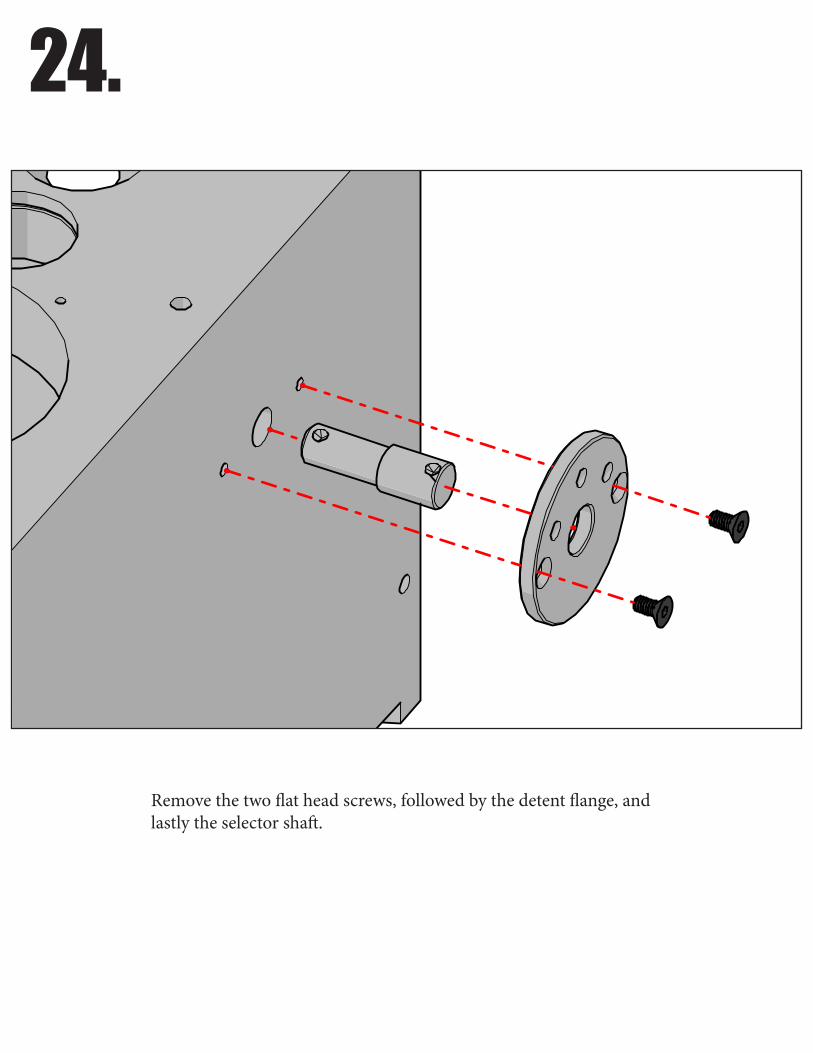
24.
Remove the two flat head screws, followed by the detent flange, and lastly the selector shaft.
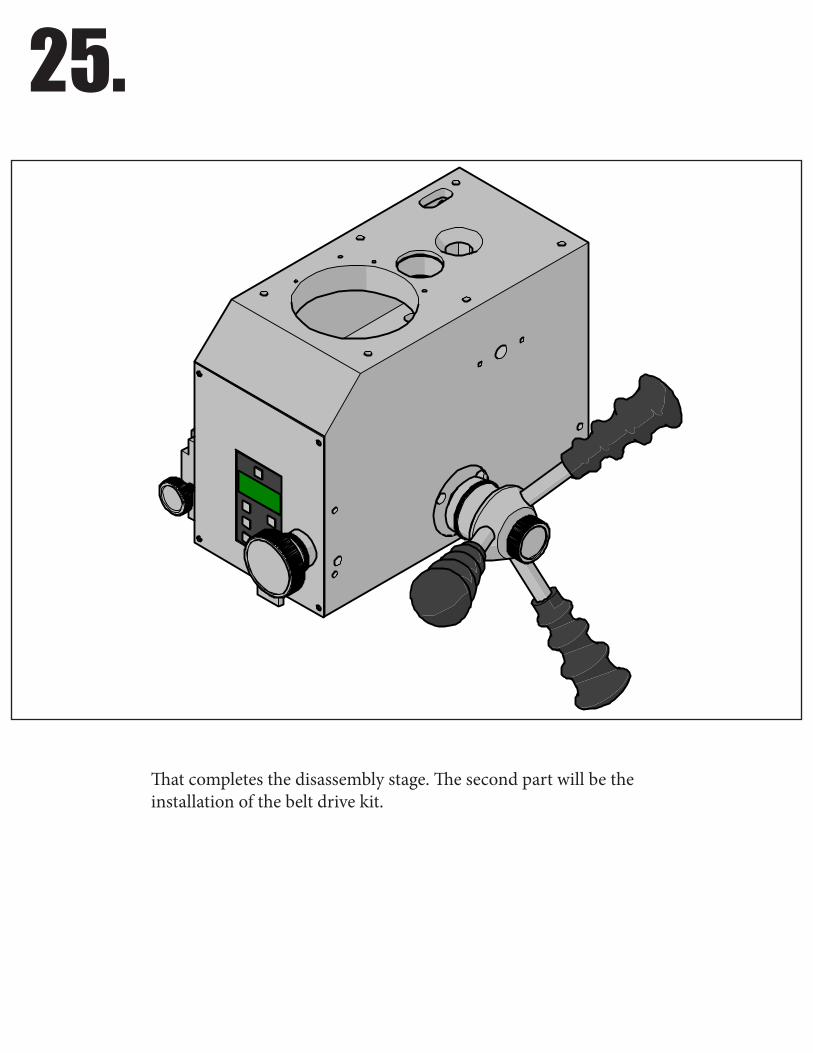
25.
That completes the disassembly stage. The second part will be the installation of the belt drive kit.
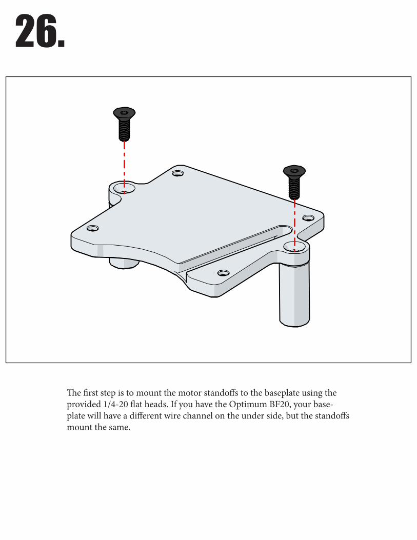
26.
The first step is to mount the motor standoffs to the baseplate using the provided 1/4-20 flat heads. If you have the Optimum BF20, your base-plate will have a different wire channel on the under side, but the standoffs mount the same.
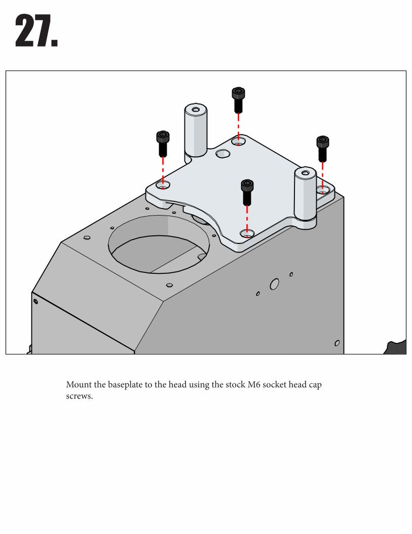
27.
Mount the baseplate to the head using the stock M6 socket head cap screws.
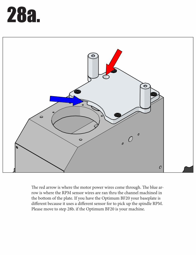
28a.
The red arrow is where the motor power wires come through. The blue ar-row is where the RPM sensor wires are ran thru the channel machined in the bottom of the plate. If you have the Optimum BF20 your baseplate is different because it uses a different sensor for to pick up the spindle RPM. Please move to step 28b. if the Optimum BF20 is your machine.

28b.
The red arrow is where the motor power wires come through. The blue arrow is where the RPM sensor wires are ran thru the channel machined in the bottom of the plate. This step is for the Optimum BF20 mill only.
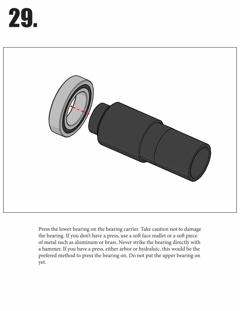
29.
Press the lower bearing on the bearing carrier. Take caution not to damage the bearing. If you don’t have a press, use a soft face mallet or a soft piece of metal such as aluminum or brass. Never strike the bearing directly with a hammer. If you have a press, either arbor or hydraluic, this would be the prefered method to press the bearing on. Do not put the upper bearing on yet.
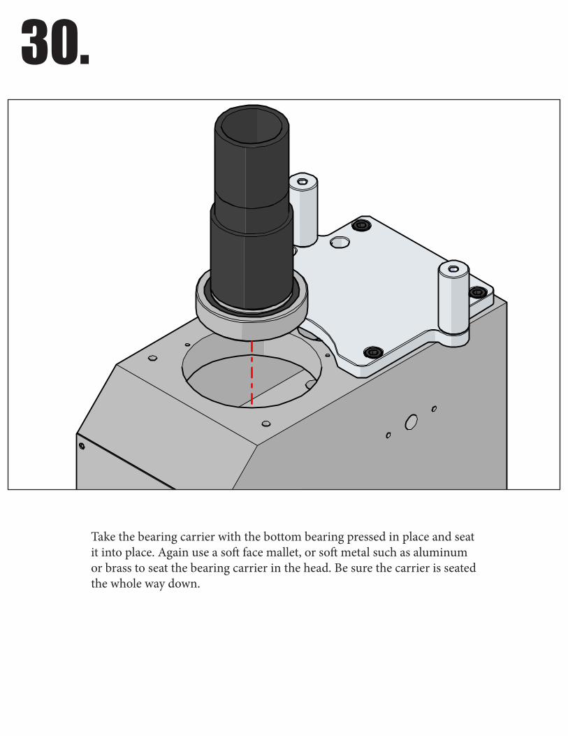
30.
Take the bearing carrier with the bottom bearing pressed in place and seat it into place. Again use a soft face mallet, or soft metal such as aluminum or brass to seat the bearing carrier in the head. Be sure the carrier is seated the whole way down.
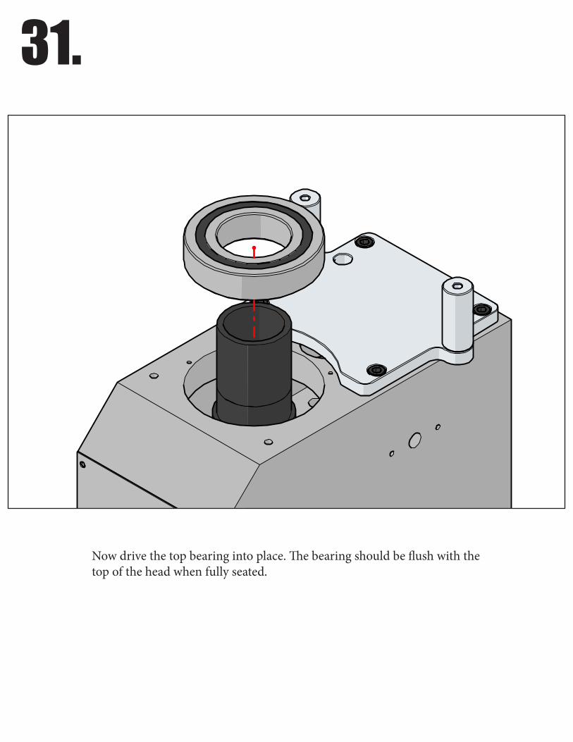
31.
Now drive the top bearing into place. The bearing should be flush with the top of the head when fully seated.
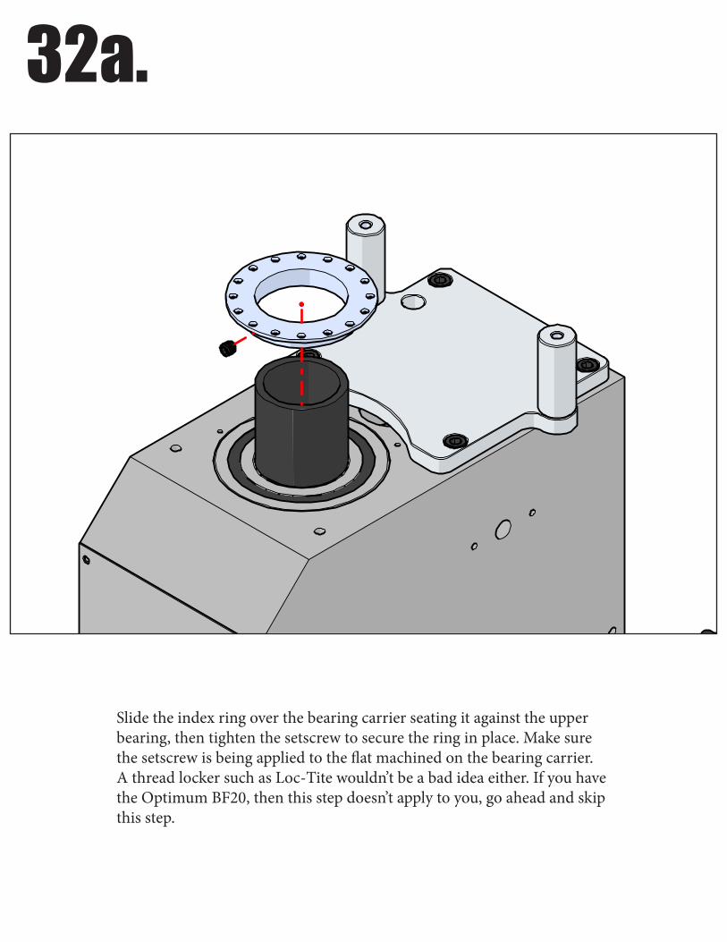
32a.
Slide the index ring over the bearing carrier seating it against the upper bearing, then tighten the setscrew to secure the ring in place. Make sure the setscrew is being applied to the flat machined on the bearing carrier. A thread locker such as Loc-Tite wouldn’t be a bad idea either. If you have the Optimum BF20, then this step doesn’t apply to you, go ahead and skip this step.
32b.
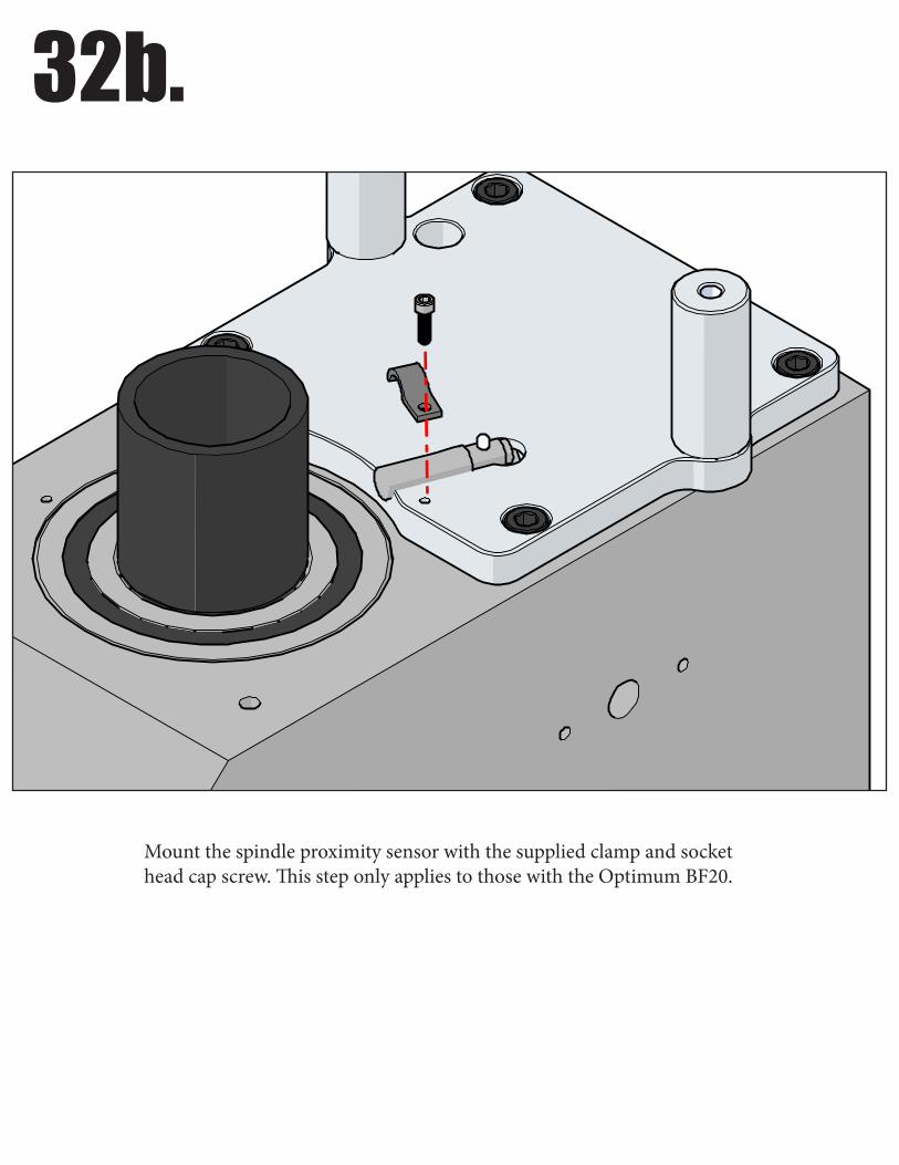
Mount the spindle proximity sensor with the supplied clamp and socket head cap screw. This step only applies to those with the Optimum BF20.
33.
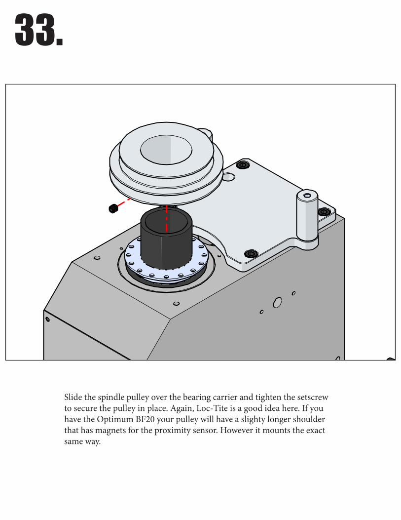
Slide the spindle pulley over the bearing carrier and tighten the setscrew to secure the pulley in place. Again, Loc-Tite is a good idea here. If you have the Optimum BF20 your pulley will have a slighty longer shoulder that has magnets for the proximity sensor. However it mounts the exact same way.
34.
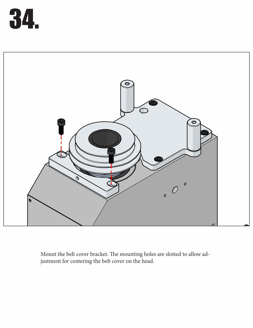
Mount the belt cover bracket. The mounting holes are slotted to allow ad-justment for centering the belt cover on the head.
35.
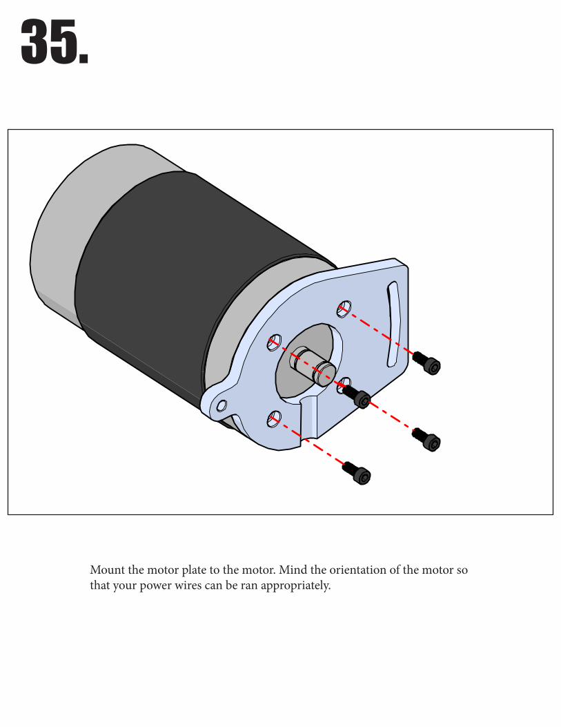
Mount the motor plate to the motor. Mind the orientation of the motor so that your power wires can be ran appropriately.

36.
Mount the motor pulley onto the motor. There are two setscrews 90° apart that lock the motor pulley in place. The groove machined in the motor plate is to allow you to make adjustments of the motor pulley. You may just want to snug these for now as you will probably need to adjust the pulley to make sure it’s in line with the spindle pulley.
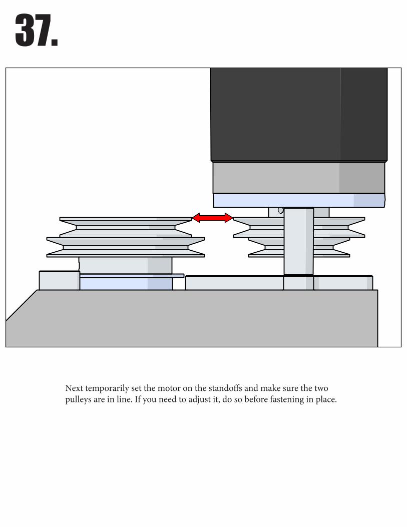
37.
Next temporarily set the motor on the standoffs and make sure the two pulleys are in line. If you need to adjust it, do so before fastening in place.
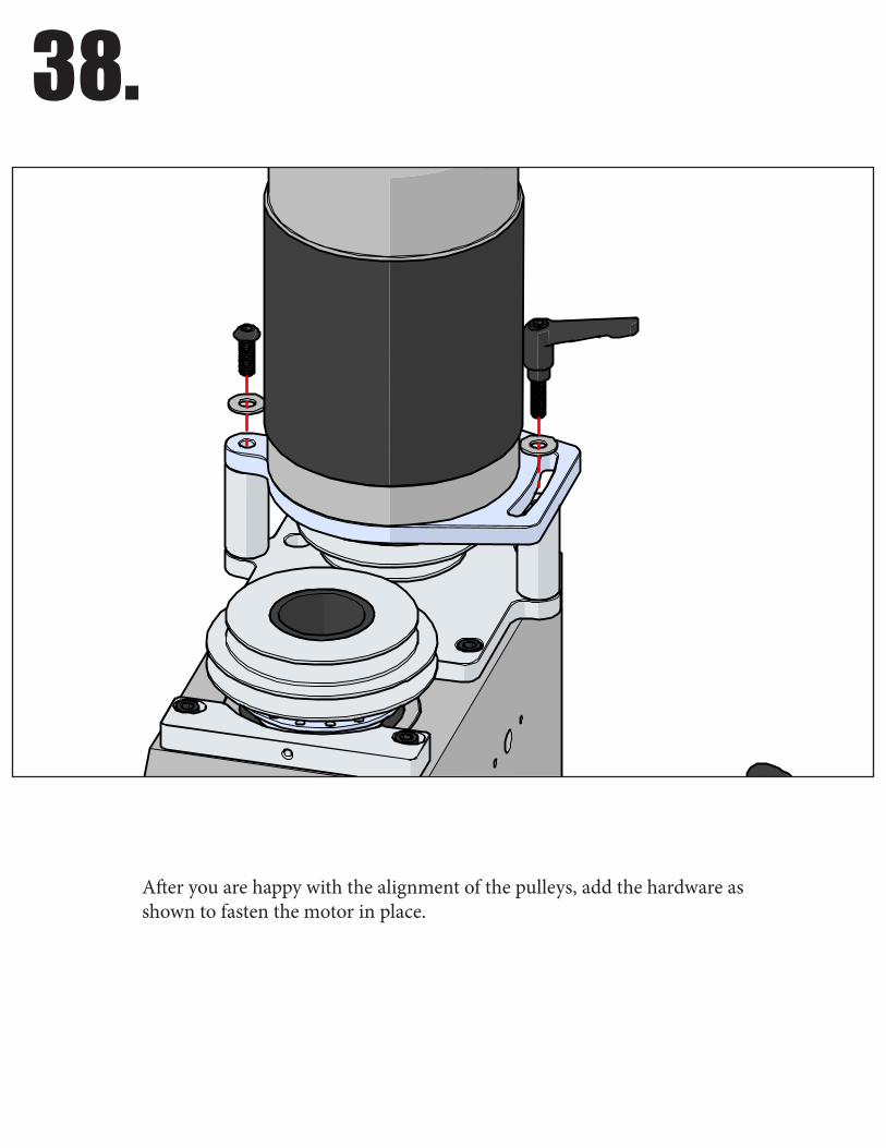
38.
After you are happy with the alignment of the pulleys, add the hardware as shown to fasten the motor in place.
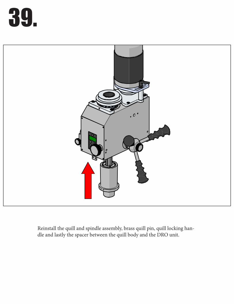
39.
Reinstall the quill and spindle assembly, brass quill pin, quill locking han-dle and lastly the spacer between the quill body and the DRO unit.

40.
Reinstall the quill spring.
41.
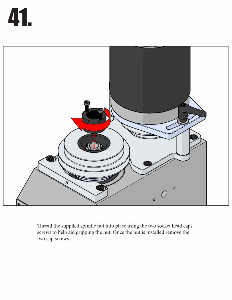
Thread the supplied spindle nut into place using the two socket head caps screws to help aid gripping the nut. Once the nut is installed remove the two cap screws.
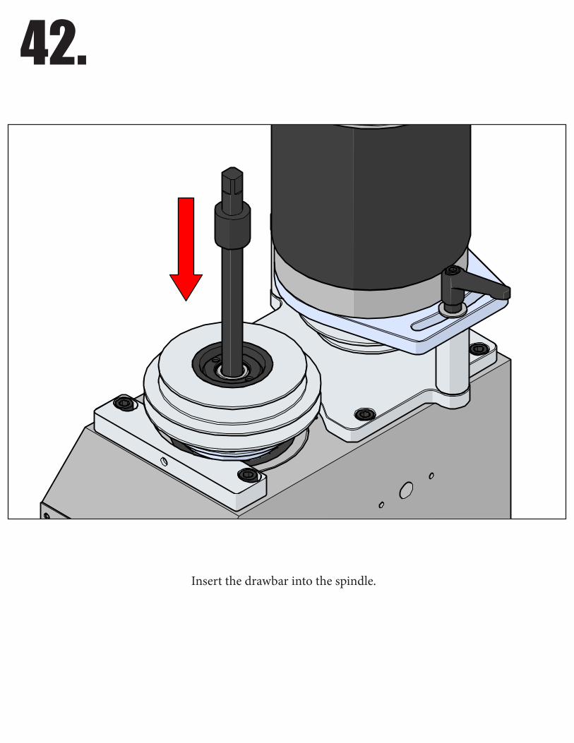
42.
Insert the drawbar into the spindle.
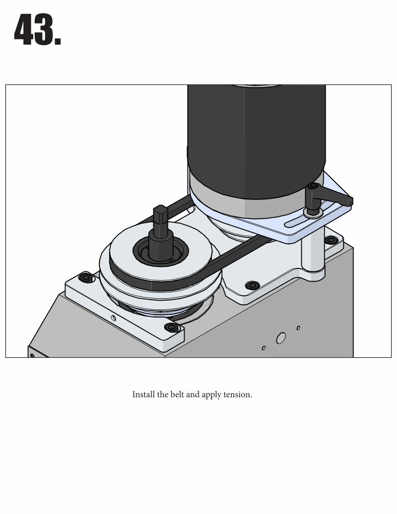
43.
Install the belt and apply tension.
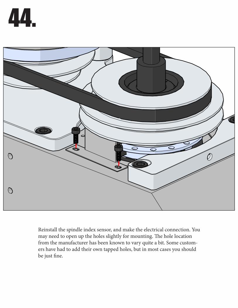
44.
Reinstall the spindle index sensor, and make the electrical connection. You may need to open up the holes slightly for mounting. The hole location from the manufacturer has been known to vary quite a bit. Some custom-ers have had to add their own tapped holes, but in most cases you should be just fine.
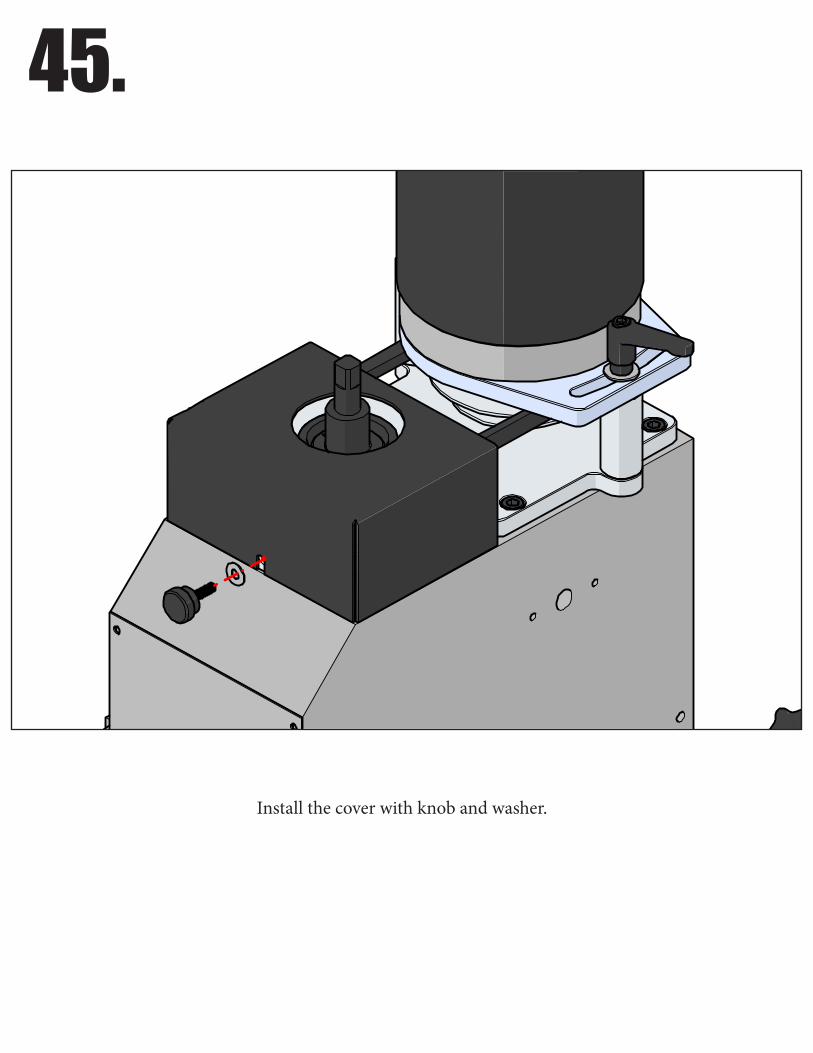
45.
Install the cover with knob and washer.
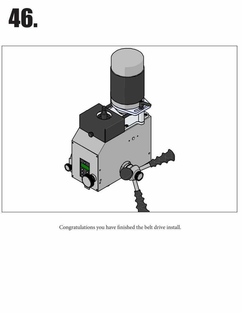
46.
Congratulations you have finished the belt drive install.
Recommended


