1213ACI Structural Journal/September-October 2014
ACI STRUCTURAL JOURNAL TECHNICAL PAPER
Seven intermediate-scale slabs were constructed and tested to failure under sequential drop-weight impacts. The slabs contained longitudinal reinforcing bars and were constructed with steel fiber contents ranging from zero (that is, conventional rein-forced concrete) to 1.50% by volume. The data from the testing program were used to further assess the performance of steel fiber- reinforced concretes in impact-resistant applications and to provide a well-documented dataset pertaining to a research area which is currently limited within the literature. The test results showed that the addition of the steel fibers was effective in increasing slab capacity, reducing crack widths and spacings, and mitigating local damage under impact. Although the slabs in the program were designed to be flexure-critical under static loading conditions, the development of inertial forces under impact loading conditions led to observed responses and failure modes that were governed by shear.
Keywords: drop-weight impact; fiber-reinforced concrete; impact capacity; impact test; inertia; punching shear; steel fibers.
INTRODUCTIONThe behavior of reinforced concrete under impact is an
area of research that is still not well understood; however, work in this area continues to be motivated by a broad range of applications. Examples include reinforced concrete structures designed to resist accidental loading scenarios such as falling rock impact; vehicle or ship collisions with buildings, bridges, or offshore facilities; and structures that are used in high-threat or high-hazard applications, such as military fortification structures or nuclear facilities. As a result, considerable work has been undertaken in an effort to develop impact-resistant design procedures and to improve the performance of reinforced concrete structures subjected to impact loads.
To date, the majority of the impact-related research has been focused on developing empirical provisions to esti-mate member damage1,2 and capacity3 under specific types of impact-loading scenarios. When used to provide impact response estimates under conditions that differ from those considered in their development, the application of such formulae has been met with limited success.4 Moreover, with respect to wall and slab elements specifically, much of the work has been exclusively focused on localized damage mechanisms such as concrete scabbing, impactor (that is, missile) penetration, and impactor perforation.5-7 Although it is commonly accepted that reinforced concrete elements under impact generally respond in such a way that impact energy is dissipated through a combination of local damage development and global element deformations (bending, shear, and axial deformations),1 often little effort is focused
on studying the global response behaviors of reinforced concrete elements under impact.8
In recent decades, the use of fiber-reinforced concrete has emerged as a viable approach for improving the perfor-mance of concrete elements under impact. Several investi-gations have shown that compared with reinforced concrete, fiber-reinforced concrete elements containing traditional steel reinforcing bars (R/FRC elements) exhibit superior resistances to local damage development and, as a result, possess improved energy absorption capabilities under impact.9-11 As such, in the case of R/FRC elements, the global impact response can often be of greater significance than the formation of local damage mechanisms.
This paper presents the methodology and findings from an experimental program undertaken to investigate and document the impact behaviors of reinforced concrete (RC) and steel fiber-reinforced concrete slabs containing steel reinforcing bars (R/FRC slabs). Emphasis was placed on assessing the influence of end-hooked steel fibers on the measured slab behavior and, in contrast to much of the related experimental work available in the literature, on investigating the global dynamic impact responses of the slabs as well as local damage development. In an effort to fully capture the global impact behaviors, the slabs in this testing program were well-instrumented, and the test data collected were used to provide an openly accessible dataset that can be used by others to develop and assess related analytical procedures.
RESEARCH SIGNIFICANCEThere is growing realization of the need for resilient
structures and, as a result, a need for adequate, related assessment and design procedures. With respect to impact- resistant structures, the development of such procedures has been hindered by a lack of high-quality experimental data.4
This paper presents the performance and findings from an experimental program undertaken to investigate RC and R/FRC slabs under high-mass, low-velocity impact. Test data are used to assess the influence of steel fibers on impact response, to analyze global slab behavior, and to contribute to an area of research in which limited data are currently available.
Title No. 111-S103
Behavior of Steel Fiber-Reinforced Concrete Slabs under Impact Loadby Trevor D. Hrynyk and Frank J. Vecchio
ACI Structural Journal, V. 111, No. 5, September-October 2014.MS No. S-2013-161.R1, doi: 10.14359/51686923, was received September 12,
2013, and reviewed under Institute publication policies. Copyright © 2014, American Concrete Institute. All rights reserved, including the making of copies unless permission is obtained from the copyright proprietors. Pertinent discussion including author’s closure, if any, will be published ten months from this journal’s date if the discussion is received within four months of the paper’s print publication.

1214 ACI Structural Journal/September-October 2014
EXPERIMENTAL PROCEDURE
Specimen designSeven intermediate-scale slab specimens, identified as
Slabs TH2 through TH8, were constructed and tested under drop-weight impact (Fig. 1). Three slabs were constructed using plain concrete, and four slabs were constructed from a steel fiber-reinforced concrete (SFRC) mixture design with varied volumes of end-hooked steel fibers. Both concrete mixtures were adapted from 50 MPa (7.3 ksi) nominal cylinder-strength designs developed previously,12 and are reported in Table 1. Two parameters were varied amongst the slabs: the steel fiber volume fraction Vf, which ranged from zero to 1.5%, and the longitudinal reinforcement ratio rl, which was equal in the planar directions of the slabs and ranged from 0.273 to 0.592% per layer. The program test matrix is presented in Table 2.
The slabs were 1800 mm (71 in.) square, 130 mm (5.1 in.) thick, and were doubly reinforced with equal amounts of steel in the top and bottom mats of reinforcement, with each reinforcement mat being comprised of two orthogonal reinforcement layers. To accommodate different longitu-dinal reinforcement ratios, two types of reinforcing bars were used: No. 3 (U.S.) mild bars with cross-sectional areas of 71 mm2 (0.11 in.2) and nominal diameters of 9.5 mm (0.38 in.), and No.10M bars with cross-sectional areas of 100 mm2 (0.16 in.2) and nominal diameters of 11.3 mm (0.45 in.). Steel links constructed from bent No. 3 bars were used in the corner and center regions of the slabs to join the top and bottom reinforcement mats together. The typical longitudinal reinforcement layout is illustrated in Fig. 2.
The R/FRC slabs were constructed using end-hooked steel fibers with the following nominal properties: fiber length of 30 mm (1.18 in.), diameter of 0.37 mm (0.015 in.), aspect ratio of 80, and ultimate tensile strength of 2300 MPa
(330 ksi). The geometry of the end-hooked steel fiber used is illustrated in Fig. 3. Concrete material tests in the form of standard compression cylinders, bending prisms, and dog-bone shaped direct tension specimens were performed to characterize the mechanical properties of the concrete and to provide test data that are often required for the develop-ment of numerical models. Sample results illustrating the influence of the steel fibers on the compressive stress-strain responses of the concrete and the post-cracking tensile stress softening behaviors of the steel fiber-reinforced concrete are presented in Fig. 4. It should be noted that direct tension tests were not performed for the plain concrete; however, brittle responses characterized by rapid post-cracking strength loss were observed from the flexural testing of the plain concrete prisms. Mean mechanical properties developed from the concrete material tests and coupon tests of the steel rein-forcing bars are summarized in Table 3. Additional details regarding the material test specimens, the testing procedures used, and the response measurements obtained from each material test performed are available elsewhere.13
Fig. 1—Drop-weight test frame.
Table 1—Concrete dry mixture proportions
Water, kg/m3 (lb/yd3)
Cement, kg/m3 (lb/yd3)
Sand, kg/m3
(lb/yd3)CA*, kg/m3
(lb/yd3)WR*, mL
(fl oz)SP*, mL(fl oz)
R*, mL(fl oz)
Plain 139 (234) 375 (632) 847 (1428) 1080 (1820) 1000 (33.8) 3500 (118) 488 (16.5)
SFRC† 163 (275) 500 (843) 1114 (1878) 792 (1335) 2750 (93.0) 3500 (118) 650 (22.0)*CA = 13 mm (1/2 in.) crushed limestone coarse aggregate; WR is water reducer; SP is high-range water-reducing admixture; and R is retarder.†79 kg/m3 (133 lb/yd3) steel fibers required per 1.0% fiber volume.
Table 2—Test matrix
SlabLongitudinal reinforce-
ment ratio rl*, %
Reinforcing bar/spacing, mm (in.)
Fiber volume fraction Vf, %
TH2 0.420 No. 3/130 (5.1) —
TH3 0.420 No. 3/130 (5.1) 0.50
TH4 0.420 No. 3/130 (5.1) 1.00
TH5 0.420 No. 3/130 (5.1) 1.50
TH6 0.273 No. 3/200 (7.9) —
TH7 0.592 10M/130 (5.1) —
TH8 0.592 10M/130 (5.1) 1.00
*Based on total section height, per layer of steel.

1215ACI Structural Journal/September-October 2014
The slabs in this study were restrained at their corners and impacted at their centers. They were designed such that under conventional static loading conditions (that is, under concentrated midpoint loading), flexure-critical failure modes would govern their capacities. The nominal flexural load capacities PF of the RC slabs were estimated using yield line theory14 and their nominal resistances to
punching PV were computed in accordance with ACI 318-08 design provisions.15 From the static strength estimates reported in Table 4, it is apparent that under conventional loading conditions, the nominal design responses of the RC slabs are controlled by flexure. Previous experimental studies pertaining to R/FRC beams16,17 using similar quanti-ties and types of end-hooked steel fibers as that comprising the R/FRC slabs in this study have shown that although the addition of the steel fibers tended to affect the cracking behaviors (crack development, spacings, widths) and
Fig. 2—Typical reinforcement configuration.
Fig. 3—End-hooked steel fiber. Fig. 4—Concrete material test results.
Table 3—Concrete and reinforcing bar properties
Parent slab, age in days
Compressive cylinderstrength* fc′, MPa (ksi)
Strain atpeak compressivestress* εo (× 10–3)
Compressive secant modulus*
Ecs, MPa (ksi)
Flexural tensilestrength† fr, MPa
(psi)
Direct tensilestrength† ft′, MPa
(psi)Tensile secant modulus†
Ets, MPa (ksi)
TH2 (318) 69.4 (10.1) 2.554 36,800 (5340) 8.51 (1230) NA‡ NA‡
TH3 (304) 48.0 (7.0) 2.802 28,800 (4180) 6.90 (1000) 4.57 (660) 32,800 (4760)
TH4 (340) 48.6 (7.0) 3.296 25,600 (3710) 7.98 (1160) 4.09 (590) 29,400 (4260)
TH5 (340) 50.7 (7.4) 4.188 23,300 (3380) 8.76 (1270) 4.05 (590) 24,500 (3550)
TH6 (284) 59.0 (8.6) 2.670 32,000 (4640) 7.92 (1150) NA‡ NA‡
TH7 (319) 60.3 (8.7) 2.635 34,600 (5020) 8.09 (1170) NA‡ NA‡
TH8 (353) 45.1 (6.5) 3.367 24,000 (3480) 6.14 (890) 3.81 (550) 29,500 (4280)
Reinforcing barElastic modulus Es, MPa
(ksi)Yield stress fy, MPa
(ksi)Tensile strength
fu, MPa (ksi)
No. 3 193,000 (28,000) 489 (70.9) 597 (86.6)
10M 201,700 (29,300) 439 (63.7) 564 (81.8)*Material testing coincided with parent slab test age.†Material testing performed upon completion of slab testing.‡Not available, evaluated for SFRC only.

1216 ACI Structural Journal/September-October 2014
the ductilities of flexure-critical beams, the fiber content generally had limited influence on the maximum load- carrying capacities of the beams. As such, it was assumed that the failure loads of the R/FRC slabs in this study would also be governed by flexure under static loading conditions and that their nominal flexural capacities could be estimated as being approximately equal to those of the RC slabs.
Test setupPrevious experimental studies have shown that elements
under impulsive loading conditions often display significant rebounding leading to specimen uplift.3,18 As such, a testing frame that restrained the positive and negative vertical trans-lations, but allowed the corners of the slabs to rotate freely, was provided (Fig. 5). To stabilize the slabs under the highly impulsive loading condition, the lateral restraint conditions provided beneath the slabs were varied amongst the four corner supports. On the top surfaces of the slabs, spherical bearings that reacted against stiff hollow structural sections (HSS) were used to prevent the corners of the slabs from lifting off of the supports. High-strength rods anchored the HSS members to support columns, which were fixed to a concrete strong floor. The rods were pre-tensioned such that minimal forces (approximately 5 kN [1.1 kip] per rod) were transferred from the test frame assembly to each corner of the slabs.
The slabs in this experimental program were well- instrumented. Typically, 25 potentiometers were used to measure the transverse and lateral slab displacements. Thir-teen accelerometers were used in each test: 11 to measure transverse slab accelerations, and two to characterize the applied drop-weight impact force. Longitudinal reinforcing bars from each of the four layers of steel comprising the slabs were instrumented with electrical-resistance strain gauges. The high-strength rods forming the test frame were also instrumented with strain gauges to measure uplift (nega-tive) reaction forces. Load cells were provided at each of the four corner supports to measure the positive vertical reac-tion forces. Instrument measurements were collected using a digital data acquisition system, and were acquired without filtering. Data collected from the accelerometers and the load cells were sampled at a rate of 96 kHz, and data collected from the potentiometers and strain gauges were sampled at 2.4 kHz. An instrumentation plan showing the typical locations of the accelerometers and potentiometers is presented in Fig. 6.
Additional details pertaining to the locations and character-istics of the instruments used are provided elsewhere.13
Impact loads were generated using a drop-weight testing method. The weight was constructed from a concrete filled, 300 mm (11.8 in.) square, HSS member that was guided using a vertical rail assembly suspended above the
Table 4—Reinforced concrete slab static strength estimates
Reinforced concrete
slab
Longitudinal reinforcement
ratio rl, %
Nominal flexural
strength PF,*
kN (kip)
Nominal shear strength PV,* kN (kip) PV/PF
TH2 0.420 170 (38) 400 (90) 2.4
TH6 0.273 115 (26) 400 (90) 3.5
TH7 0.592 225 (51) 400 (90) 1.8
*Using fc′ = 50 MPa (7.3 ksi); fy = 500 MPa (72.5 ksi).
Note: Concentrated loading area = 300 x 300 mm (11.8 x 11.8 in.).
Fig. 5—Test setup.
Fig. 6—Typical accelerometer and potentiometer instru-mentation plan.
1217ACI Structural Journal/September-October 2014
testing frame. Steel mounts welded to the sides of the HSS allowed the mass of the drop-weight to be adjusted by way of removable plates. The striking face of the drop-weight consisted of a 25 mm (1 in.) thick, 300 mm (11.8 in.) square steel plate with a flat contact surface. The contact face of the drop-weight directly impacted the slabs, producing a hard-impact loading condition.1 The slabs were tested under sequential impacts of increasing mass, with constant impact velocities. The drop-height of the impacting mass was set at 3.26 m (10.7 ft) above the top surface of the slab, resulting in a nominal impact velocity of 8.0 m/s (26.2 ft/s), which was verified using high-speed photography. The slabs were subjected to a common loading protocol comprised of sequential impact events with mass levels ranging from 150 to 300 kg (331 to 660 lb). Using data from preliminary pilot slab tests,13 the initial mass level was selected such that the first impact event resulted in appreciable slab damage without causing failure. Over the progression of impacts, the mass level was typically increased by increments of 30 kg (66 lb); however, impacts of repeated mass levels were used to investigate the gradual stiffness degradation of the R/FRC slabs under the later stage events (Table 5). Testing termi-nation for each of the slabs was governed by occurrence of any one of the following criteria: 1) the full 10 impact event loading protocol was completed; 2) the peak support reaction forces decreased significantly from those measured during prior impacts; or 3) the severely damaged state of the slab greatly increased the likelihood of damaging instrumen-tation under additional impacts.
EXPERIMENTAL RESULTS AND DISCUSSIONTest results pertaining to observed damage and measured
response characteristics are presented in the following sections. Selected results are used to characterize the responses of the slabs under impact and to illustrate the influence of the end-hooked steel fibers. The acquired test data from all impact events are available online in digital format.19 A more comprehensive listing of test observations and cracking patterns developed under individual impact events are reported elsewhere.13
Crack patterns and damageThe observed damage and crack development was found
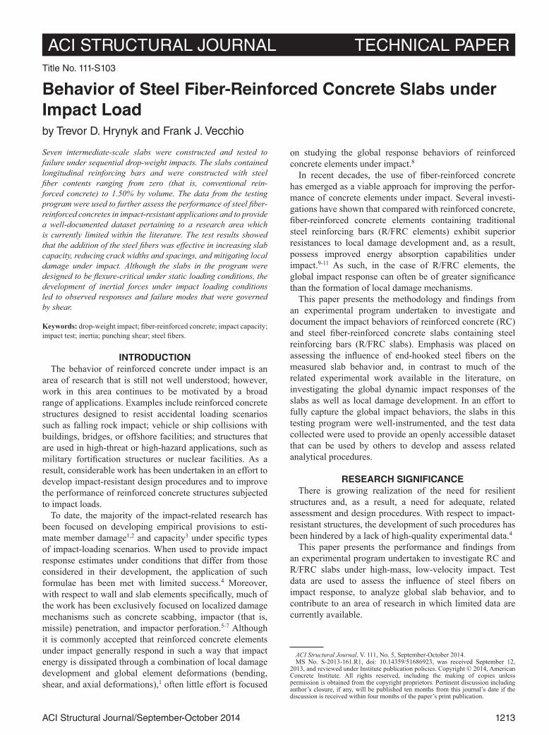
to be typical amongst the RC slabs (TH2, TH6, and TH7). Under the first impact test, cracking patterns aligned with the reinforcing bar grids developed on both surfaces of the slabs. The widest cracks were oriented circumferentially on the bottom surfaces, with widths ranging from 0.50 to 0.60 mm (0.020 to 0.026 in.); no concrete scabbing and limited mass penetration were observed. Subsequent impacts led to concrete scabbing indicative of punching shear, which developed outside of the impact region and stemmed from circumferential cracks developed under prior impacts. RC
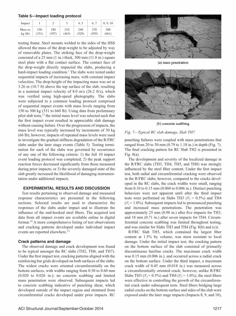
punching failures were coupled with mass penetrations that ranged from 20 to 30 mm (0.79 to 1.18 in.) in depth (Fig. 7). The final cracking pattern for RC Slab TH2 is presented in Fig. 8(a).
The development and severity of the localized damage in the R/FRC slabs (TH3, TH4, TH5, and TH8) was strongly influenced by the steel fiber content. Under the first impact test, both radial and circumferential cracking were observed in the R/FRC slabs; however, compared to the cracks devel-oped in the RC slabs, the crack widths were small, ranging from 0.10 to 0.15 mm (0.004 to 0.006 in.). Distinct punching behaviors were not apparent until after the third impact tests were performed on Slabs TH3 (Vf = 0.5%) and TH4 (Vf = 1.0%). Subsequent impacts led to pronounced punching and increased mass penetrations. The penetration was approximately 25 mm (0.98 in.) after five impacts for TH3, and 18 mm (0.71 in.) after seven impacts for TH4. Circum-ferential concrete scabbing was limited throughout testing, and was similar for Slabs TH3 and TH4 (Fig. 8(b) and (c)).
R/FRC Slab TH5, which contained the largest fiber content at 1.5% by volume, was most resistant to local damage. Under the initial impact test, the cracking pattern on the bottom surface of the slab consisted of primarily discontinuous hairline cracks. The maximum crack width was 0.15 mm (0.006 in.), and occurred across a radial crack on the bottom surface. Under the third impact, a maximum crack width of 0.45 mm (0.018 in.) was measured across a circumferentially oriented crack; however, unlike R/FRC Slabs TH3 (Vf = 0.5%) and TH4 (Vf = 1.0%), the steel fibers were effective in controlling the growth of the circumferen-tial crack under subsequent tests. Steel fibers bridging large radial cracks on the bottom surface and sides of the slab were exposed under the later stage impacts (Impacts 8, 9, and 10),
Table 5—Impact loading protocol
Impact 1 2 3 4, 5 6, 7 8, 9, 10
Mass m,kg (lb)
150 (331)
180 (397)
210(463)
240(529)
270(595)
300(661)
Fig. 7—Typical RC slab damage, Slab TH7.
1218 ACI Structural Journal/September-October 2014
and a concentration of wide radial cracks that extended from the midpoint toward the southwest edge of the slab was observed. Upon completion of the 10 impact load protocol (refer to Table 5), the maximum mass penetration (which occurred locally within the impact region) was limited to
a depth of 6.5 mm (0.26 in.), no dominant circumferential punching crack was evident, and no concrete scabbing had occurred (Fig. 9). The maximum residual crack width was 3.5 mm (0.14 in.), and was measured across a radial crack on the bottom surface. Multiple radial cracks with widths greater than 2.0 mm (0.08 in.) were observed. In addition to the noted growth of the radial crack widths, permanent deformations of the slab indicative of extensive longitudinal steel yielding were visibly apparent.
The noted reductions in concrete scabbing and localized punching resulting from the increased steel fiber contents is evident from the final cracking patterns for Slabs TH2, TH3, TH4, and TH5, presented in Fig. 8. The figure also illustrates the reduced crack spacings observed in the R/FRC slabs.
Impact capacitiesAs the slabs in this program were tested under a common
loading protocol and subject to uniform testing termination criteria, the total kinetic energy imparted to each of the slabs can be used to provide an estimate of the relative impact capacities of the slabs. It should be noted that because testing termination for R/FRC Slab TH5 was governed by load protocol completion as opposed to damage related criteria, the relative capacity obtained for Slab TH5 should be treated as a lower-bound estimate.
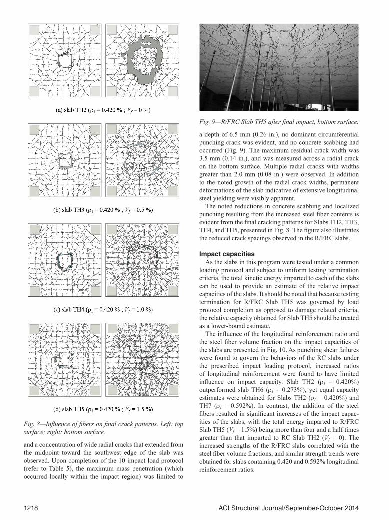
The influence of the longitudinal reinforcement ratio and the steel fiber volume fraction on the impact capacities of the slabs are presented in Fig. 10. As punching shear failures were found to govern the behaviors of the RC slabs under the prescribed impact loading protocol, increased ratios of longitudinal reinforcement were found to have limited influence on impact capacity. Slab TH2 (rl = 0.420%) outperformed slab TH6 (rl = 0.273%), yet equal capacity estimates were obtained for Slabs TH2 (rl = 0.420%) and TH7 (rl = 0.592%). In contrast, the addition of the steel fibers resulted in significant increases of the impact capac-ities of the slabs, with the total energy imparted to R/FRC Slab TH5 (Vf = 1.5%) being more than four and a half times greater than that imparted to RC Slab TH2 (Vf = 0). The increased strengths of the R/FRC slabs correlated with the steel fiber volume fractions, and similar strength trends were obtained for slabs containing 0.420 and 0.592% longitudinal reinforcement ratios.
Fig. 8—Influence of fibers on final crack patterns. Left: top surface; right: bottom surface.
Fig. 9—R/FRC Slab TH5 after final impact, bottom surface.

1219ACI Structural Journal/September-October 2014
Measured response progressionMidpoint displacement-time and support reaction-time
histories are presented for Slabs TH2 and TH4 in Fig. 11. It should be recalled that these slabs were nominally identical with the exception that R/FRC Slab TH4 contained 1.0% steel fibers by volume, and RC Slab TH2 was constructed from plain concrete. The displacement-time histories shown represent event displacements and do not illustrate the accu-mulation of residual midpoint displacements from prior impacts. The results from the fourth (TH4-4) and the sixth (TH4-6) impact tests performed on Slab TH4 have been omitted from the figure and, for discussion purposes, the displacement-time histories for Slab TH2 (Fig. 11(a)) are also included in Fig. 11(b).
The displacement-time histories for Slab TH2 were found to be typical of those measured for the RC slabs. With each impact event performed, the RC slabs exhibited progressively increasing peak and residual event displace-ments, and elongation of the displacement response periods. The addition of steel fibers reduced the peak and residual displacements, particularly for impacts performed on previ-ously damaged slabs (that is, second and third impacts). Increased post-cracking stiffness was common to all R/FRC slabs, and is illustrated from the comparison of the displace-ment-time histories for Slabs TH2 and TH4, presented in Fig. 11(b). The influence of the steel fiber content and the longitudinal reinforcement ratio on the progression of the midpoint displacements under the repeated impact loading protocol are summarized in Fig. 12(a). Compared with the RC slabs, the R/FRC slabs exhibited smaller displacement amplitudes under like impacts, and were able to undergo larger displacements amplitudes before failure. The ultimate displacement capacities of the R/FRC slabs were found to correlate with the steel fiber contents provided. In a manner similar to that of the relative slab capacities, increasing the longitudinal reinforcement ratios of the RC slabs had limited influence on the progression of the midpoint displacements. From Fig. 12(a), it can be seen that increasing the longitu-dinal reinforcement ratio from 0.273% (RC Slab TH6) to 0.420% (RC Slab TH2) resulted in a stiffer slab response. As is apparent from the near identical displacement progres-sions presented for RC Slabs TH2 and TH7, no appreciable change in stiffness was observed when the longitudinal rein-forcement ratio was further increased from 0.420 to 0.592%.
Seemingly unaffected by the longitudinal reinforcement ratio, similar displacement capacities were achieved by all RC slabs.
The reaction forces from the four corner supports have been combined to evaluate total slab reactions that are considered exclusively in the following discussion. The peak support reaction forces measured under each impact were found to be indicative of the slabs post-cracking stiff-
Fig. 10—Relative impact energy capacity.
Fig. 11—Displacement and support reaction time histories.
1220 ACI Structural Journal/September-October 2014
ness, and large reductions in the support reactions from one impact to another typically coincided with the development of notable slab damage (for example, punching shear cone formation, mass penetration, and concrete scabbing). From Fig. 12(b), it can be seen that as the fiber volume of the slabs increased, the reduction of the peak reaction forces under the later stage impacts tended to decrease more gradually. It should also be noted that, in agreement with results reported by others studying RC members under high-mass low- velocity impact,3,5 the peak reaction forces were typically measured to be approximately three to four times greater
than the estimated static capacities of the slabs presented in Table 4.
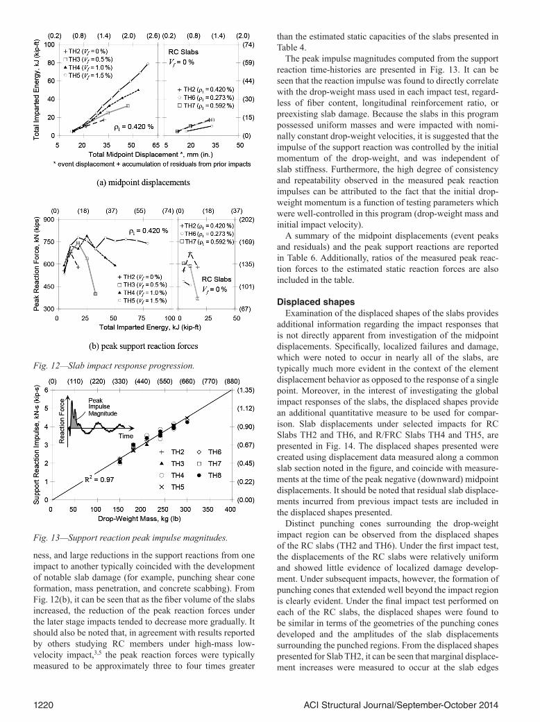
The peak impulse magnitudes computed from the support reaction time-histories are presented in Fig. 13. It can be seen that the reaction impulse was found to directly correlate with the drop-weight mass used in each impact test, regard-less of fiber content, longitudinal reinforcement ratio, or preexisting slab damage. Because the slabs in this program possessed uniform masses and were impacted with nomi-nally constant drop-weight velocities, it is suggested that the impulse of the support reaction was controlled by the initial momentum of the drop-weight, and was independent of slab stiffness. Furthermore, the high degree of consistency and repeatability observed in the measured peak reaction impulses can be attributed to the fact that the initial drop-weight momentum is a function of testing parameters which were well-controlled in this program (drop-weight mass and initial impact velocity).
A summary of the midpoint displacements (event peaks and residuals) and the peak support reactions are reported in Table 6. Additionally, ratios of the measured peak reac-tion forces to the estimated static reaction forces are also included in the table.
Displaced shapesExamination of the displaced shapes of the slabs provides
additional information regarding the impact responses that is not directly apparent from investigation of the midpoint displacements. Specifically, localized failures and damage, which were noted to occur in nearly all of the slabs, are typically much more evident in the context of the element displacement behavior as opposed to the response of a single point. Moreover, in the interest of investigating the global impact responses of the slabs, the displaced shapes provide an additional quantitative measure to be used for compar-ison. Slab displacements under selected impacts for RC Slabs TH2 and TH6, and R/FRC Slabs TH4 and TH5, are presented in Fig. 14. The displaced shapes presented were created using displacement data measured along a common slab section noted in the figure, and coincide with measure-ments at the time of the peak negative (downward) midpoint displacements. It should be noted that residual slab displace-ments incurred from previous impact tests are included in the displaced shapes presented.
Distinct punching cones surrounding the drop-weight impact region can be observed from the displaced shapes of the RC slabs (TH2 and TH6). Under the first impact test, the displacements of the RC slabs were relatively uniform and showed little evidence of localized damage develop-ment. Under subsequent impacts, however, the formation of punching cones that extended well beyond the impact region is clearly evident. Under the final impact test performed on each of the RC slabs, the displaced shapes were found to be similar in terms of the geometries of the punching cones developed and the amplitudes of the slab displacements surrounding the punched regions. From the displaced shapes presented for Slab TH2, it can be seen that marginal displace-ment increases were measured to occur at the slab edges
Fig. 12—Slab impact response progression.
Fig. 13—Support reaction peak impulse magnitudes.

1221ACI Structural Journal/September-October 2014
under the third and final impact, suggesting that little, if any, additional damage occurred outside of the punched region.
The displaced shapes of the R/FRC slabs were significantly different from those measured for the RC slabs, as they were found to remain symmetric and regular over the progression of several impacts. Increased displacements immediately surrounding, and within, the impact region were ultimately found to occur in all of the R/FRC slabs; however, the cause of the localized displacement behaviors tended to vary. In the case of Slab TH4 (Vf = 1.0%), localized displacements are initially observed to occur immediately outside of the impact region under the third impact test, and progressively become more prominent under subsequent impacts. Under the seventh and final impact performed on the slab, the noted punching behavior that was coupled with extensive mass penetration seems to be only marginally apparent from the displaced shape of the slab. It can be seen that compared with the RC slabs, the punched area of TH4 is much more local-ized within the impact region, and the relative increase in the displacement amplitude is substantially less severe. R/FRC Slab TH5 (Vf = 1.5%) exhibited a displaced shape that was relatively symmetric and increased uniformly in amplitude throughout the majority of the loading protocol. Under the final impact events (Impacts 8, 9, and 10), the development of localized displacements can still be observed to occur on one side of the impact region; however, no distinct punching region was observed during testing, and little mass pene-tration had occurred. In this case, the previously discussed
Table 6—Impact response characteristics
Impact event
slab-impact
Peak midpoint displacement*,
mm (in.)
Residual midpoint
displacement*, mm (in.)
Peak total reaction force R, kN (kip) R/RS
†
TH2-1 13.2 (0.52) 2.7 (0.11) 556 (125) 3.3
TH2-2 18.7 (0.74) 3.0 (0.12) 676 (152) 4.0
TH2-3 26.6 (1.05) 8.9 (0.35) 580 (130) 3.4
TH3-1 NA‡ 2.9 (0.12) 523 (118) 3.1
TH3-2 17.3 (0.68) 1.0 (0.04) 684 (154) 4.0
TH3-3 22.0 (0.87) 3.3 (0.13) 743 (167) 4.4
TH3-4 27.3 (1.07) 7.1 (0.28) 637 (143) 3.7
TH3-5 32.5 (1.28) 13.3 (0.52) 401 (90) 2.4
TH4-1 14.0 (0.55) 2.7 (0.11) 591 (133) 3.5
TH4-2 17.0 (0.67) 1.0 (0.04) 724 (163) 4.3
TH4-3 21.6 (0.85) 2.2 (0.09) 703 (158) 4.1
TH4-4 24.1 (0.95) 3.7 (0.14) 789 (177) 4.6
TH4-5 25.9 (1.02) 4.6 (0.18) 701 (158) 4.1
TH4-6 29.2 (1.15) 6.9 (0.27) 643 (145) 3.8
TH4-7 32.0 (1.26) 9.1 (0.36) 591 (133) 3.5
TH5-1 12.4 (0.49) 3.4 (0.13) 531 (119) 3.1
TH5-2 15.2 (0.60) 0.6 (0.02) 725 (163) 4.3
TH5-3 19.3 (0.76) 1.7 (0.06) 779 (175) 4.6
TH5-4 22.2 (0.87) 2.8 (0.11) 756 (170) 4.4
TH5-5 22.9 (0.90) 2.8 (0.11) 703 (158) 4.1
TH5-6 25.7 (1.01) 4.0 (0.16) 777 (175) 4.6
TH5-7 26.3 (1.04) 4.0 (0.16) 755 (170) 4.4
TH5-8 29.1 (1.15) 5.4 (0.21) 766 (172) 4.5
TH5-9 29.4 (1.16) 4.4 (0.17) 759 (171) 4.5
TH5-10 29.8 (1.17) 4.2 (0.16) 739 (166) 4.3
TH6-1 18.3 (0.72) 6.2 (0.24) 483 (109) 4.2
TH6-2 27.7 (1.09) 11.4 (0.45) 458 (103) 4.0
TH7-1 12.8 (0.51) 2.6 (0.10) 605 (136) 2.7
TH7-2 18.3 (0.72) 3.3 (0.13) 588 (132) 2.6
TH7-3 28.5 (1.12) 11.5 (0.45) 368 (83) 1.6
TH8-1 13.5 (0.53) 2.7 (0.11) 621 (140) 2.8
TH8-2 17.0 (0.67) 0.7 (0.03) 721 (162) 3.2
TH8-3 20.4 (0.80) 1.0 (0.04) 759 (171) 3.4
TH8-4 23.7 (0.93) 2.5 (0.10) 772 (174) 3.4
TH8-5 25.0 (0.98) 3.2 (0.13) 720 (162) 3.2
TH8-6 27.3 (1.07) 4.4 (0.17) 767 (172) 3.4
TH8-7 27.5 (1.08) 5.2 (0.20) 692 (156) 3.1
TH8-8 31.5 (1.24) 8.8 (0.35) 684 (154) 3.0
*Relative to zeroed displacement values at start of each impact event.†RS is estimated static capacity (that is, minimum of PF and PV in Table 4).‡Not available.
Fig. 14—Displaced shapes.
1222 ACI Structural Journal/September-October 2014
development of concentrated wide radial cracks observed to occur under the final stages of testing are believed to be the primary cause of the localized displacements developed in Slab TH5.
In comparing all of the displaced shapes presented in Fig. 14, it can be seen that because the steel fibers were successful in mitigating the development of localized fail-ures, the R/FRC slabs exhibited displaced shapes in which deformations were more uniformly distributed and, as a result, were capable of achieving larger displacement ampli-tudes before failure.
Inertial effectsDue to the high rates of loading experienced by structures
under impact, element inertia can play a significant role in the structural response, and can often lead to dynamic loading distributions that differ significantly from those observed under conventional static loading conditions. In this study, eight accelerometers were used to densely instru-ment quarter-surface regions of the slabs (Fig. 6). As all of the slabs in this study possessed uniform planar densities (that is, constant thicknesses), the measured slab accelera-tions were used to estimate the distribution of inertial forces acting on the slabs. Between the locations of the accelerome-ters, the slab accelerations were estimated using bi-quadratic interpolation functions commonly employed for nine-noded Lagrangian finite elements.20 Additionally, it was assumed that the slab accelerations at the support restraint locations were negligible and, as such, were taken to be zero.
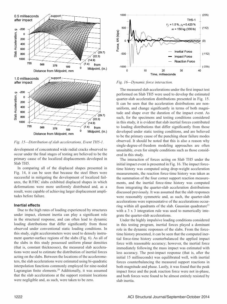
The measured slab accelerations under the first impact test performed on Slab TH5 were used to develop the estimated quarter-slab acceleration distributions presented in Fig. 15. It can be seen that the acceleration distributions are non- uniform, and change significantly in terms of both magni-tude and shape over the duration of the impact event. As such, for the specimens and testing conditions considered in this study, it is evident that slab inertial forces contributed to loading distributions that differ significantly from those developed under static testing conditions, and are believed to be the primary cause of the punching shear failure modes observed. It should be noted that this is also a reason why single-degree-of-freedom modeling approaches are often unsuitable, even for simple conditions such as those consid-ered in this study.
The interaction of forces acting on Slab TH5 under the initial impact event is presented in Fig. 16. The impact force-time history was computed using drop-weight acceleration measurements, the reaction force-time history was taken as the summation of the four corner support reaction measure-ments, and the inertial force-time history was computed from integrating the quarter-slab acceleration distributions discussed previously. It was assumed that the slab responses were reasonably symmetric and, as such, the quarter-slab accelerations were representative of the accelerations occur-ring within all quadrants of the slab. Gaussian quadrature21 with a 3 x 3 integration rule was used to numerically inte-grate the quarter-slab accelerations.
Under the highly impulsive loading conditions considered in this testing program, inertial forces played a dominant role in the dynamic responses of the slabs. From the force-time history presented, it can be seen that the computed iner-tial force-time history counterbalanced the applied impact force with reasonable accuracy; however, the inertial force immediately following the mass impact was estimated with less accuracy. The post-impact response (that is, after the initial 15 milliseconds) was equilibrated well, with inertial forces counterbalancing the measured support reactions in both magnitude and phase. Lastly, it was found that the peak impact force and the peak reaction force were not in-phase, and both forces were found to be almost entirely resisted by slab inertia.
Fig. 15—Distribution of slab accelerations, Event TH5-1.
Fig. 16—Dynamic force interaction.

1223ACI Structural Journal/September-October 2014
CONCLUSIONSThe purpose of this experimental program was to investi-
gate the impact performance of RC and R/FRC slabs under repeated high-mass low-velocity impact. Primary objectives were focused on assessing the influence of the end-hooked steel fibers on impact performance and capturing the global impact response behaviors of the slabs. Additionally, a docu-mented, openly accessible dataset is provided that can be used by others to appraise and develop analytical procedures pertaining to RC and R/FRC structures under impact.
Findings from the experimental program support the following main conclusions:
1. The R/FRC slabs exhibited superior performances under impact loading conditions when compared with nonfibrous RC slabs. The addition of end-hooked steel fibers led to reduced crack spacings and widths; mitigation of local damage mechanisms, such as mass penetration and concrete scabbing; and increased slab stiffness and capacity. The increased impact resistances, stiffnesses, and displacement capacities of the R/FRC slabs tended to correlate with the steel fiber volume fractions provided;
2. The slabs forming the experimental program were designed such that they would be governed by flexural failure modes under conventional static loading condi-tions; however, all but one of the slabs were controlled by punching shear failures under impact. Inertial force develop-ment, which was shown to result in dynamic loading condi-tions that differ from those encountered under static testing, is suggested to be the main contributor to the punching shear failure modes observed. R/FRC Slab TH5, which contained the largest fiber volume fraction considered in the study (Vf = 1.5%), was the only slab that prevented punching from occurring under the prescribed impact loading protocol;
3. Under high-mass, low-velocity impact loading condi-tions, the behaviors of the slabs were not exclusively governed by local failure mechanisms. Global deformations contributed to the impact responses of all slabs, and the influence of local damage development was found to be of less significance in the R/FRC slabs; and
4. As the slabs in this study were ultimately controlled by punching shear failures under impact, limited benefits were attained as a result of increasing the longitudinal rein-forcement ratios of the RC slabs. For example, RC Slabs TH2 (rl = 0.420%) and TH7 (rl = 0.592%) exhibited similar performance characteristics in terms of strength, stiffness, and local damage development.
AUTHOR BIOSACI member Trevor D. Hrynyk is an Assistant Professor in the Depart-ment of Civil, Architectural and Environmental Engineering at the Univer-sity of Texas at Austin, Austin, TX. He received his PhD from the University of Toronto, Toronto, ON, Canada, in 2013. His research interests include performance assessment and analysis of reinforced concrete structures, response under extreme loads, and application of fiber-reinforced concrete.
Frank J. Vecchio, FACI, is a Professor in the Department of Civil Engi-neering at the University of Toronto. He is a member of Joint ACI-ASCE Committees 441, Reinforced Concrete Columns, and 447, Finite Element Analysis of Reinforced Concrete Structures. He received the 1998 ACI Structural Research Award, the 1999 ACI Structural Engineer Award, and the 2011 ACI Wason Medal for Most Meritorious Paper. His research interests include advanced constitutive modeling and analysis of reinforced
concrete, assessment and rehabilitation of structures, and response under extreme loads.
ACKNOWLEDGMENTSFinancial support provided by the Natural Sciences and Engineering
Research Council of Canada (NSERC) and material donations provided by N. V. Bekaert S. A., Sika Canada Inc., Holcim Canada Inc., Lafarge Cements, Dufferin Aggregates, and BASF Canada are gratefully acknowledged.
REFERENCES1. Kennedy, R. P., “A Review of Procedures for the Analysis and Design
of Concrete Structures to Resist Missile Impact Effects,” Nuclear Engi-neering and Design, V. 37, No. 2, 1976, pp. 183-203.
2. Sliter, G. E., “Assessment of Empirical Concrete Impact Formulas,” Journal of the Structural Division, ASCE, V. 106, No. 5, 1980, pp. 1023-1045.
3. Kishi, N., and Mikami, J., “Empirical Formulas for Designing Rein-forced Concrete Beams under Impact Loading,” ACI Structural Journal, V. 109, No. 4, July-Aug. 2012, pp. 509-519.
4. Chen, Y., and May, I. M., “Reinforced Concrete Members under Drop Weight Impacts,” Proceedings of the Institution of Civil Engineers. Struc-tures and Buildings, V. 1, 2009, pp. 45-56.
5. Hughes, G., “Hard Missile Impact on Reinforced Concrete,” Nuclear Engineering and Design, V. 77, No. 1, 1984, pp. 23-35.
6. Sawamoto, Y.; Tsubota, H.; Kasai, Y.; Koshika, N.; and Morikawa, H., “Analytical Studies on Local Damage to Reinforced Concrete under Impact Loading by Discrete Element Method,” Nuclear Engineering and Design, V. 179, No. 2, 1998, pp. 157-177.
7. Li, Q. M.; Reid, S. R.; Wen, H. M.; and Telford, A. R., “Local Impact Effects of Hard Missiles on Concrete Targets,” International Journal of Impact Engineering, V. 32, No. 1-4, 2005, pp. 224-284.
8. Saatci, S., and Vecchio, F. J., “Effects of Shear Mechanisms on Impact Behavior of Reinforced Concrete Beams,” ACI Structural Journal, V. 106, No. 1, Jan.-Feb. 2009, pp. 78-86.
9. Ong, K. C. G.; Basheerkhan, M.; and Paramasivam, P., “Behavior of Fiber-Reinforced Concrete Slabs under Low Velocity Projectile Impact,” High-Performance Concrete—Proceedings: ACI International Conference, Malaysia 1997, SP-172, V. M. Malhotra, ed., American Concrete Institute, Farmington Hills, MI, 1999, pp. 993-1011.
10. Kurihashi, Y.; Taguchi, F.; Kishi, N.; and Mikami, H., “Experimental Study on Static and Dynamic Response of PVA Short-Fiber Mixed RC Slab,” fib Proceedings of the 2nd International Congress, ID 13-20, Naples, Italy, 2006, 10 pp.
11. Zhang, J.; Maalej, M.; and Quek, S. T., “Performance of Hybrid-Fiber ECC Blast/Shelter Panels Subjected to Drop Weight Impact,” Journal of Materials in Civil Engineering, ASCE, V. 19, No. 10, 2007, pp. 855-863.
12. Susetyo, J., “Fibre Reinforcement for Shrinkage Crack Control in Prestressed, Precast Segmental Bridges,” PhD dissertation, Department of Civil Engineering, University of Toronto, Toronto, ON, Canada, 2009, 532 pp.
13. Hrynyk, T. D., “Behaviour and Modelling of Reinforced Concrete Slabs and Shells under Static and Dynamic Loads,” PhD dissertation, Department of Civil Engineering, University of Toronto, Toronto, ON, Canada, 2013, 455 pp.
14. Johansen, K. W., Brudlinieteorier Jul. Gjellerups Forlag, Copen-hagen, 1943, 191 pp. (Yield-line Theory, translated by Cement and Concrete Association, London, UK, 1962, 181 pp.)
15. ACI Committee 318, “Building Code Requirements for Structural Concrete (ACI 318-08) and Commentary,” American Concrete Institute, Farmington Hills, MI, 2008, 473 pp.
16. Aoude, H.; Belghiti, M.; Cook, M.; and Mitchell, D., “Response of Steel Fiber-Reinforced Concrete Beams with and without Stirrups,” ACI Structural Journal, V. 109, No. 3, May-June 2012, pp. 359-367.
17. Cucchiara, C.; Mendola, L. L.; and Papia, M., “Effectiveness of Stirrups and Steel Fibres as Shear Reinforcement,” Cement and Concrete Composites, V. 26, 2004, pp. 777-786.
18. Ho, D., “Impact Response of Reinforced Concrete: An Experimental and Numerical Investigation,” MASc thesis, University of Toronto, Depart-ment of Civil Engineering, Toronto, ON, Canada, 2004, 267 pp.
19. University of Toronto-VecTor Analysis Group, Thesis Repository: Trevor Hrynyk, 2013, http://www.civ.utoronto.ca/vector.
20. Reddy, J. N., Mechanics of Laminated Composite Plates and Shells: Theory and Analysis, second edition, CRC Press, Boca Raton, FL, 2003, 831 pp.
21. Hildebrand, F. B., Introduction to Numerical Analysis, McGraw-Hill Book Co., Inc., New York, 1956, 511 pp.

1224 ACI Structural Journal/September-October 2014
NOTES:
Recommended