Computer-Aided Design 41 (2009) 1082–1094
Contents lists available at ScienceDirect
Computer-Aided Design
journal homepage: www.elsevier.com/locate/cad
Automated design process modelling and analysis using immersive virtual realityRaymond C.W. Sung a,∗, James M. Ritchie a, Graham Robinson a, Philip N. Day a, J.R. Corney b,1,Theodore Lim aa Scottish Manufacturing Institute, Heriot-Watt University, Edinburgh, EH14 4AS, UKb University of Strathclyde, Design, Manufacture & Engineering Management, 502b James Weir Building, UK
a r t i c l e i n f o
Article history:Received 23 July 2008Accepted 29 September 2009
Keywords:Virtual realityDesign task analysisCable harness designUser loggingDesign rationale and knowledge capture
a b s t r a c t
The capture of engineering design processes and associated knowledge has traditionally been extremelydifficult due to the high overhead associatedwith current intrusive and time-consumingmanualmethodsused in industry, usually involving interruption of the designer during the design task and relying onthem to remember how a design solution was developed after the event. This paper presents novelresearch which demonstrates how the detailed logging and analysis of an individual designer’s actionsin a cable harness virtual reality (VR) design and manufacturing system permits automated design taskanalysis with process mapping. Based on prior research, which utilised user-logging to automaticallyanalyse design activities and generate assembly plans, this work involves the automatic capture ofextracted design knowledge embedded within the log files and subsequently represented using IDEF0diagrams, DRed graphs, PSL, XML, annotatedmovie clips and storyboard representations. Using this designknowledge, an online help system has been demonstrated which helps users to carry out design taskssimilar to those performed previously by expert users. This is triggered by monitoring the designer’sactions and functions in real time and pushes knowledge and advice to the user which was capturedfrom experts and subsequently formalised during earlier design sessions.
© 2009 Elsevier Ltd. All rights reserved.
1. Introduction
Within product design andmanufacture, the cost of virtual real-ity (VR) tools is reducing and, in the near future, it is envisaged thatthey will become widely used throughout industry as a major partof the product life cycle process. Due to this anticipated expansion,there is a need to investigate how such VR tools could have an im-pact on the design andmanufacturing processes. In addition, somenew tools which may help increase the future use of VR need tobe researched, such as user-interface analysis and the automaticgeneration and analysis of product engineering information. Dueto the nature of VR systems, and themanner inwhich they are pro-grammed, it is straightforward to implement routines which allowuser actions to be logged unobtrusively. By analysing the informa-tion embedded in the logged data, useful design knowledge can beextracted and used as a basis for an interactive help system to trainnew users and store knowledge for future analysis and use.This paper focuses on utilising and expanding the capabili-
ties of a well tried and tested cable harness virtual aided design
∗ Corresponding author. Tel.: +44 131 451 4569; fax: +44 131 451 3129.E-mail addresses: [email protected] (R.C.W. Sung), [email protected]
(J.M. Ritchie), [email protected] (G. Robinson), [email protected] (P.N. Day),[email protected] (J.R. Corney), [email protected] (T. Lim).1 Tel.: +44 141 548 2254.
0010-4485/$ – see front matter© 2009 Elsevier Ltd. All rights reserved.doi:10.1016/j.cad.2009.09.006
(VAD) system as a tool for the analysis of industrially equivalentharness routing and assembly planning tasks. This tool has beensuccessfully compared with a number of CAD systems and foundto provide considerable productivity benefits over traditionalcomputer-based techniques [1]. Prior research, presented in [2],demonstrated that the user-logged data has been successfully usedto automatically generate assembly sequence plans and IDEF0 as-sembly diagrams. This has subsequently laid the foundations fordesign rationale capture through identifyingmethods for recognis-ing signature patterns relating to design activities for cable harnessrouting and assembly planning. In this paper, a prototype informa-tion push system is proposed which offers automated assistanceto users during a design task by combining the monitoring of useractivities and utilising design knowledge that has been previouslycaptured. Aswell as allowing expert design knowledge to be taughtto new users, it is envisaged that such a system can be used to trainengineers in maintenance-related tasks.The immersive VR apparatus is detailed in Section 2 whilst the
experimental methodology used to investigate this design domainis presented in Section 3. In Section 3, the various formal repre-sentations that have been used to represent the design knowledgeextracted from the log files are presented while, in Section 4, anoverview of how the design knowledge has been used to developan online help system is detailed. Finally, a discussion of the resultsis presented in Section 5 before ending with some conclusions.

R.C.W. Sung et al. / Computer-Aided Design 41 (2009) 1082–1094 1083
1.1. Using immersive virtual reality in engineering applications
VR takes many forms with a wide array of technologies classi-fied as being virtual environments (VE) in one form or another. VRhas, and is, being used in the engineering of products using a widevariety of technology [3]. In this paper, the focus is on a virtual envi-ronment where users wear a head-mounted display (HMD), ratherthan looking at a 3D screen or using augmented reality (AR); there-fore, users are completely immersed in the virtual environmentwith a wide field-of-view. VR systems are altering the manner inwhich engineers are developing products, concepts and planningmanufacturing processes [3,4] with a substantial number of appli-cations now being evident within the public domain. For exam-ple, [5] presents a virtual design environment for aircraft whichallow several users to collaborate together during the design stage.In [6] virtual prototypes are used for the sound quality design ofautomobiles while in [7] models of underwater vehicles are gener-ated in a virtual environment and then simulations can be run totest the design. As an example of the use of virtual tools to aid theproduction planning process [8] presents a tool which uses VR andAR technologies tomodel a factory and then run simulations to op-timise the manufacturing processes involved. Varga et al. [9] haveinvestigated hand motion as a means of creating conceptualisedgeometry for designs in a virtual environment as well as identi-fying the benefits that this form of interface brings to the designtask. Holt et al. [10] demonstrated that interactive immersive VRdoes have a role to play in the design process by being more costand time-efficient as well as giving users the tool support that isrequired in creating an effective design.As can be seen, engineering applications utilising VR are ex-
panding and are too numerous to mention in this paper. It is en-visaged that the use of VR tools will increase, so it is importantto carry out research which investigates how engineers will op-erate and function in such environments in the future. In relationto extracting design andmanufacturing information and engineer-ing knowledge, VR tools allow a new type of capture. One key as-pect of this is to take advantage of monitoring the user; this allowsboth the acquisition of geometry and system interaction informa-tion (e.g. menu choices) which, when combinedwith the user’s be-havioural data, extracts what is implicitly embedded within thetask-associated activities. This knowledge can then be made ex-plicit, formalised and, if required, passed onto other users or storedin a product lifecycle management (PLM) system. This importantavenue of research is discussed more fully in the next section.
1.2. User logging and design knowledge capture
The capture and identification of design knowledge is an im-portant aspect of product engineering at all stages of the productlife cycle because this means that vital historical product knowl-edge relating to engineering solutions can be stored and is not lostshould engineers leave the company or retire [8]. This is partic-ularly the case for long-life cradle-to-grave projects which coverlong periods of time where product engineering knowledge andinformation generated early on in the product’s life cycle can in-variably be lost [11]. Also, if this is possible, engineering knowledgecan be captured from experienced engineers and subsequently beused to train and educate inexperienced engineers on design andmanufacturing methods. This problem is compounded by the factthat existing CAD systems often have proprietary file formats thatdo not allow embedding of knowledge information [12]. This isreaffirmed in [13], which states that: ‘‘Current documentary ap-proaches are not sufficient to capture activities and decisions in theirentirety and can lead to organizations revisiting and in some casesreworking design decisions in order to understand previous design
episodes’’. In addition, traditional methods of manual knowledgecapture are labour-intensive [14] and interruptions to a user’s ac-tivity may alter the pattern of how they carry out their task [15].Using these methods, a lot of information is lost or forgotten bythe time an engineer attempts to formalise their design method orsolutions, they tend to be carried out in a non-standard fashion,and failed or less suitable alternatives (which are just as importantto engineering knowledge capture) are forgotten about or missedout. To overcome these problems, automated and unobtrusivecomputer-based logging of engineers could be utilised to generateand formalise knowledge and information aswell as the associatedprocesses. Furthermore, using automated tools can help reduce er-rors to occur during the design task, since it has been found that:‘‘Using (automated) tools to do tedious, exacting, or uninterestingtasks helps eliminate human errors by releasing people to concen-trate on more interesting work for which human intelligence is es-sential and most valuable’’ [16]. From past research experience, theopen and accessible development platforms associated with vir-tual aided design (VAD) environments provide an ideal arena inwhich to investigate the practicality of this concept. The authorsalso contend that immersiveVRprovides considerable potential forthe non-intrusive analysis of design tasks and, through the recog-nition of associated patterns of an engineer’s behaviour recognisedin the context of the task being carried out, this will be even morethe case in the well-structured downstream manufacturing plan-ning activities, such as assembly planningwhere productivity gainshave been demonstrated using both non-haptic and haptic VR [17].However, once design knowledge has been captured, it needs to
be presented in a formal and structuredmanner to allow the infor-mation to be quickly and easily understood and accessed by engi-neers [11]. Research has found that engineers can spend asmuch as30% of their time looking for and viewing various sources of designinformation and, quite often, they are unable to find useful data intheir organisation, partly because what is required is not in a suit-able format [18]. In [19], a system called ‘Process Data Warehouse’(PDW) is presented that allows the capture and re-use of designknowledge during a design of a chemical reactor. PDW performssemi-automated knowledge capture by manually importing doc-uments into the system, which then get automatically translatedinto an XML representation. Currently, the capturing of work pro-cesses and decisions is not supported and the current system canonly handle a small amount of instance data. The research in thispaperwill attempt to remedy these shortcomings by automaticallytranslating the logged user actions into XML and then automati-cally generating further, understandable formal representations ofthe work processes and decisions.Twoknowledge capture systems, calledHyper-Object Substrate
(HOS) and PHIDIAS, are detailed in [20]. PHIDIAS allows the captureof CAD designs, text, sketches, audio and video; the system thenallows the searching of the captured data, and related links canbe manually added to related items. HOS is a system used forcomputer networkdesign and it contains a store for all the differenttypes of media, such as text, line drawings, composites and spatialarrangements. To provide some structure to the captured data, textanalysis is performed on the information, such as imported e-mailsand USENET messages, to look for possible links between differentpieces of data. Another component present in the two systemsconsists of ‘critics’ which observe a user’s actions and displaysrelevant information to help improve the design. However, the twosystems presented neither automatically represent the captureddesign knowledge and information in a formalised and easilyunderstood manner, nor push this at the user.An architectural analysis method called SAAM (Software Archi-
tecture Analysis Method) is detailed in [21] where a tool calledSAAMPad is used to automatically capture and retrieve design ra-tionale during a SAAM session. This involves designing using an

1084 R.C.W. Sung et al. / Computer-Aided Design 41 (2009) 1082–1094
electronic whiteboard while an audio and video of the session isrecorded, together with the whiteboard contents. Each recordedaction is time-stamped and then used to generate electronic textsummaries and visualisations of the architecture. A limitation ofthe current system is that it cannot be used to communicate withother software architecture tools.The capability of VR for design task analysis was demonstrated
by COVIRDS (COnceptual VIRtual Design System) which showedimmersive virtual design [22] using voice commands and trackingof the hand. In this paper, the authors proposed that, during theconceptual design stage, the need to create detailed models isnot as important, so the COVIRDS system uses a shape modellingfunctionality to quickly create initial designs.Exploiting user-logged data created during a VR session, Ritchie
et al. [23] investigated the use of data in log files to automate as-sembly plans. Wyatt et al. [24] analysed the log files from a VRgeotechnical laboratory to help create a more interactive designtool. Brough et al. [25] and Schwartz et al. [26] presented a vir-tual environment, called Virtual Training Studio (VTS), where usersare trained to perform assembly tasks, and assistance is offered tothem if requested or if errors are made. Whilst users perform thepreferred assembly task, their actions are logged and then analysedto identify problems that need to be rectified by further training.VTS is one of the state-of-the-art user-logging VR systems in thecurrent research field and a few of its similar features are availablein the VR system presented in this paper. However, the major dif-ference between the two systems is that VTS is aimed at manufac-turing taskswhilst the systempresented here concentrates on bothdesign and assembly, automated user analysis, behaviour detec-tion and automated information/knowledge push and assembly.Another example of user-logging, only in a non-VR application,
is demonstrated in [27], where people were logged in a physicalmeeting environment using video cameras, audio recorders andvarious sensors as well as by monitoring a user’s computer usage.Post activity, users can train the system by contextualising com-binations of logged data against specific tasks. After this has beendone, the system can then recognise the same task being carriedout, and then the corresponding actions will automatically run.Research into user-logging and knowledge capture in a 2D CAD en-vironment has also been carried out, as presented in [28]. A plug-in has been written that allows users’ actions to be logged andthen specific sequential patterns are searched for using a pattern-recognition system. The final results show that the important de-sign operations that were carried out when designing a car doorwere successfully found. However, the design knowledge is notstored in a format which can be exported to other software appli-cations or easily accessed by users.As can be seen from this review, there is still a gap in under-
standing how product design and manufacturing processes can beanalysed in detail so that the design knowledge can be extractedfrom users’ actions and represented in an understandable format.Therefore, as well as extracting the design knowledge, the aim ofthe research in this paper is to represent the knowledge in a formalway and then utilise it, via an expert knowledge information pushsystem, to give assistance to new inexperienced engineers as wellas aiding the capture of design intent.
1.3. Research work domain
Cable harness design is a classic product engineering problemand, even with the application of CAD-based packages, mostcompanies employ physical prototypes to check the cable routing,as illustrated by the literature review in [29]. Indeed, muchresearch has been carried out in trying to discover methods ofsupporting or even automating this process [29,30].
Fig. 1. The workbench metaphor [29].
A survey of industrial companies showed that they felt that itwas still necessary to use expert human intervention to carry outfine adjustments and verify solutions for these [29].VR’s unique capability, and the manner in which users can in-
teract intuitivelywith 3Ddata,makes it a powerful toolwithwhichto carry out detailed design and manufacturing studies. The mainbenefit of using VR in this study for cable harness design is that thetask itself is flexible enough to allow some form of limited vari-ety to be built into system experiments but is restricted enough tocarry out detailed analysis of what the designer actually does [27].Earlier work in this domain [31] compared an immersive VR ca-
ble harness design environment with a number of CAD systems,showing the former gave large productivity benefits during cre-ative cable routing design. Follow-on work [32] was aimed at un-derstanding the degree to which various aspects of the immersiveVR system were contributing to these benefits and how engineer-ing design and planning processes could be analysed in detail. Thiswas based on the table-topmetaphor (Fig. 1), using comprehensiveuser-logging to non-intrusively collect detailed information relat-ing to design solutions generated by a number of engineers, thefocus being on the 3D volumetric design aspect.The design categorisation developed, and subsequently auto-
matically generated from users’ actions, gave the first indicationsof how design tasks performed in a virtual environment can be au-tomatically analysed. After this research, work began on addingan automated assembly planning functionality and an analysis ofusers’motions and interfacewhich pointed to opportunities for au-tomatically providing syntax descriptions of design and manufac-turing activities in a manner not previously thought possible [23].Thework presented in this paper takes advantage of previousworkin user-logging by extending the research into the domains of cap-turing embedded implicit design knowledge in log files and thenformalising it. Finally, by using this knowledge, a novel engineer-ing knowledge and information push system is presented whichaims to aid a user during particular aspects of the design task.
2. Apparatus and experimental procedure
The experimental platform developed for this research, calledCOSTAR (Cable Organisation System Through Alternative Reality),comprises an SGI r© Octane2TM with V12 dual head graphics driv-ing each eye on a V8 stereo HMD. Peripherals were a Flock ofBirds r©magnetic tracking system and Pinch r© Gloves with the sys-tem software platform being SENSE8 r©’s WorldToolKit r© release 9.Using COSTAR, the engineer can design and assembly-plan ca-
ble harness assemblies within the immersive VR environment,with all design functions being performed whilst immersed in thesystem, as schematically-shown in Fig. 2.Interactions were originally achieved using a hierarchical ring
menu system [22,29], but this has since been superseded by an

R.C.W. Sung et al. / Computer-Aided Design 41 (2009) 1082–1094 1085
Fig. 2. The COSTAR cable harness design system.
Fig. 3. Hierarchical ring menu.
icon-based user interface, shown in Fig. 3, and glove pinch gesturessupported by spatial input given by the Flock of BirdsTM system.An engineer inputs cable harness routes by plotting points in
3D space which are then linked together to produce a segmentedcable path. Subsequent cable editing is possible by selecting pointsand bending them around obstructions or bundling them. Userscan also insert new points and add connectors and fasteners. Fig. 4shows the system in use.As a user operates the system, COSTAR logs all of the cable har-
ness design and assembly activity-related actions and stores thesein a log file, as shown in Fig. 5.
In previous work, three constrained design tasks were devel-oped and implemented to evaluate each designer’s time on thesystem [23]. These covered common harness design activities suchas routing, bundling, cable modification and choosing connectors.After 10 participants completed the three tasks, 30 log files weregenerated and thesewere subsequently analysed to identify whichareas of the virtual design system were used, the type of activ-ity performed and the activity distribution within the total designtime.From the results of the user trials, areas of improvement were
identified, such as a need to replace the ring-menu system to im-prove access speeds to the design tools, and also the requirementfor better navigational facilities when moving through the virtualenvironment. Since the COSTAR system logs all user actions whilstworking on a cable assembly, assembly sequence plans could alsobe automatically generated by the system [2].
3. Formalisation of design knowledge
Prior work, presented in [2,23], has shown the potential for ex-tracting design activities using immersive VR and capturing de-sign knowledge and representing it in a formal way. To allow thisknowledge to be more easily viewed, analysed and imported intoother knowledge-based systems, it is important that the informa-tion is formally represented in a format supported by applicationsused in industry. A wide variety of possible output configurationswere investigated after discussion with both academic and indus-trial colleagues; as well as these formats, a number of new for-mats were developed which were deemed to be of use. As hasbeen found through discussionswith our industrial partners, whenthe various output formats were agreed, although a great deal ofthe design they carry out is original in its conception, a greaterpart of the embodiment and detailed design processes use exist-ingmethods and techniques from previous concepts and products.The tools researched in this study could be used to advise inexperi-enced engineers carrying out these activities, to adhere to companystandards and methods, as well as for training. It was eventuallydecided to use the following outputs to test the supposition thatthe automatic generation of engineering knowledge and processesused is actually possible, namely:
• Process Specification Language (PSL) [33] and eXtensibleMarkup Language (XML) [34];
• English syntax;• Integrated computer-aided design DEFinitions (IDEF) dia-grams [35];
• Design Rationale Editor (DRed) diagrams [36];• Storyboards; and• Annotated video capture.
Fig. 4. Creating a cable from point to point (left) and inserting a cable point (right).

1086 R.C.W. Sung et al. / Computer-Aided Design 41 (2009) 1082–1094
Fig. 5. COSTAR log file.
Table 1PSL representation of 3 design tasks.
3.1. PSL & XML
PSL andXMLgive coded representations of the design process ina format that is supported by many industry applications. By real-time monitoring of the log file during a design session, both PSLand XML outputs are automatically generated simultaneously. PSLis used to model processes used in many situations, such as man-ufacturing and production, and it only consists of the constants,functions and variables required to describe the processes; how-ever, it needs a language to connect them into a formal structure.One language used is known as the Knowledge Interchange Format(KIF) and is designed to allow straightforward translation betweendifferent software packages [37]. This means that user activity pat-terns can be imported into other knowledge or design packages.The PSL sequences can also be translated into human-readable in-structions as well as UML or IDEF0 diagrams. In Table 1, the PSLsequences that are automatically generated, in real-time, whenperforming three design tasks is shown.The three sets of PSL statements represent the processes that
occurred when the engineer moved a cable from one position toanother, which is known as a ‘‘drag and drop’’ operation, when anew bulkhead connector was created and when an assembly se-quence plan was generated.In addition to the PSL representation, XML outputs are also
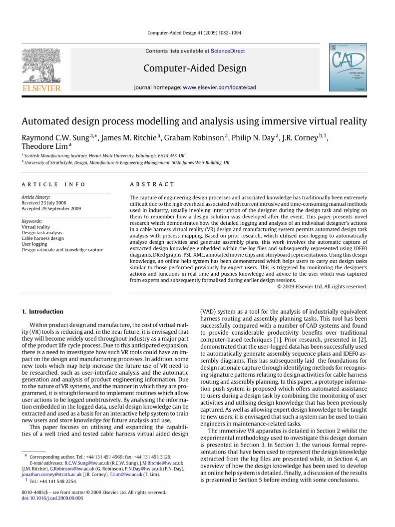
automatically generated in real-time, during a VR session. SinceXML is widely supported in many applications, it will allow thedata to be easily imported. The XML representation for the samethree design tasks is shown in Table 2.
By analysing the PSL and XML sequences that are generatedby several expert users then, by looking for repeating patterns ofaction sequences, the ‘best practice’ for each specific design taskcan be isolated and then used to train new users. Furthermore, byhaving a database of XML and PSL fragments, and then constantlymonitoring in real-time a user’s XML or PSL output during a task,the system can automatically identify when a user is carrying outa specific task. When this happens, an online help system can beautomatically activated to offer relevant help to users, if required;this is described in Section 5.
3.2. English-syntax instructions
Another important output that is automatically generated fromthe PSL log files are English-syntax instructions which give a textsummary of the processes that occurred during a design session.By capturing the actions of an expert user and then representing itin this form, it gives an easily-accessed and simple-to-follow set ofinstructions that can be used to train new users. Tables 3–5 showsan example of simple instructions that have been generated for thesame three cable design tasks from Section 3.1, which aremoving acable, creating a connector and carrying out an assembly sequenceplanning task.As shown from the tables, detailed information is contained in
the instructions, such as the specific cables and connectors to use,as well as their exact spatial positions. The tables also explicitlyshow which section of the PSL representation, that has beenparsed automatically, has been identified and used to generate the
R.C.W. Sung et al. / Computer-Aided Design 41 (2009) 1082–1094 1087
Table 2XML representation of 3 design tasks.
Table 3PSL & English-syntax instructions for cable drag and drop task.
Table 4PSL & English-syntax instructions for create connector task.
Table 5PSL & English-syntax instructions for assembly planning task.

1088 R.C.W. Sung et al. / Computer-Aided Design 41 (2009) 1082–1094
Fig. 6. IDEF0 diagram components.
corresponding English-syntax instruction. For example, in Table 3,the parser searches through the PSL sequences to look for linesthat start with ‘‘cablepointname’’ to identify the name of the cablepoint. If a line is found, the second term in the identified line isextracted, which in the example is ‘A01H01C01S01P02’, and it isused to construct a sentence that describes the named cable pointbeingmoved. Similarly, to construct the English-syntax phrase thatdescribes why the cable was moved, the PSL parser looks for aline beginning with ‘‘occurrence_of’’. In the Table 3 example, thevariable associated with this line is ‘‘physicalObstruction’’, so theconstructed phrase mentions that the reason for moving the cableis because of a physical interference. The same string-matchingtechnique is used to construct the English-syntax phrases for the‘create connector’ and ‘assembly sequence planning’ tasks.
3.3. IDEF diagrams
IDEF0 diagrams were developed to give a visual representationof the processes which have occurred in the modelled system.
For this research, IDEF0 diagrams are used to give a formalrepresentation of users’ actions during a design task in the COSTARenvironment. As illustrated in Fig. 6, an IDEF0 diagram includes theFUNCTION component which represents the main activity that istaking place and is used to transform the INPUT, which is an objector data, into the OUTPUT. The CONTROL component represents theconstraints on the system and the MECHANISM is the means ofwhich the activity can take place.To generate the IDEF0 diagrams, the PSL representation of a de-
sign session was imported into a spreadsheet and amacro was runwhich parses the data and automatically plots an IDEF0 diagramrepresentation, as shown in Fig. 7.In this example, the top of Fig. 7 shows the PSL representation
for an assembly sequence planning session, which is the same onein Sections 3.1 and 3.2, is parsed and an IDEF0 diagram is gener-ated for each block of PSL data, as shown at the bottom of Fig. 7.For example, the three lines of PSL data belonging to section ‘‘A’’corresponds to section ‘‘A’’ of the IDEF0 diagram. In Fig. 8, an IDEF0diagram for a generic assembly sequence plan is illustrated to ex-plicitly show the three main steps of a cable assembly sequenceplan, which are bulkhead connector assembly, cable harness as-sembly and cable harness installation.These IDEF0 diagrams show clearly, in a readable and under-
standable format, the steps that the engineer is required to per-form to successfully complete a full assembly sequence plan for acable harness. Also, by viewing these diagrams, it can give an ex-pert user a quickway to identify the important processes that haveoccurred during a design or assembly planning session, which canthen be isolated and used to train new users or to inform engineersrevisiting the process for a future design change. Such outputs caneasily be referenced and stored on the product life cycle manage-ment (PLM) system.
Fig. 7. Assembly planning PSL (top) and automated generation of IDEF0 diagram (bottom).

R.C.W. Sung et al. / Computer-Aided Design 41 (2009) 1082–1094 1089
Fig. 8. Assembly planning IDEF0 diagram.
3.4. DRed graphs
As a way of mapping the design rationale that is created duringa design session, DRed (Design Rationale Editor) was developed byKim et al. [36] in collaborationwith a number of aeronautical com-panies. The purpose of this tool is to allow the engineer tomanuallylog all of the design decisions that have occurred as a design pro-gresses. However, for the research described in this paper, the gen-eration of these graphs have been automated by creating a parserto parse the cable harness design system log files and automaticallyoutput a DRed graph structure. In Fig. 9, the DRed graph that repre-sents the processes that have occurred during the same assemblysequence plan task from Sections 3.1–3.3 is shown; dotted lineshave been added to the figure to highlight the three main stages ofthe assembly planning process, which are bulkhead connector as-sembly, cable harness assembly and cable harness installation, aspreviously mentioned.In Fig. 9, each logged user action is represented by a green
symbol (called an element), and each of these elements are con-nected with a colour-coded arrow. The elements can representitems such as issues, answers, pro, con arguments and text state-ments. As an addition to the usual Dred specification, task timeshave been added to the diagrams. If the time in between a task isquick (less than 5 s), then the arrow is coloured green. However, ifthe time ismore, the arrowwill be amber and, eventually, it will bered to indicate the user has spent a long time on a particular task.This will aid in the identification of problems that have occurredduring a design session and what areas in terms of design solu-tion or engineer trainingmay require attention. Note that this timeclassification is for demonstration purposes only but shows howdesign tasks’ interaction can be a potential measure of engineer-ing experience and may determine the level of confidence in thesolution. Since this is only a preliminary result, the time intervalsused to represent each arrow colour have not yet been finalised,so it may change in future research. However, this gives an earlyindication of how behavioural analysis potentially becomes possi-ble when analysing design activities, giving a new extension to thetools available to capture expert knowledge. Another very impor-tant output apparent from this diagram is that alternative solutionstried by the engineer are also automatically logged and formallyrepresented. This automatic capturing of wrong or less suitable so-lutions overcomes a major drawback in current manual systems.
3.5. Storyboard representation
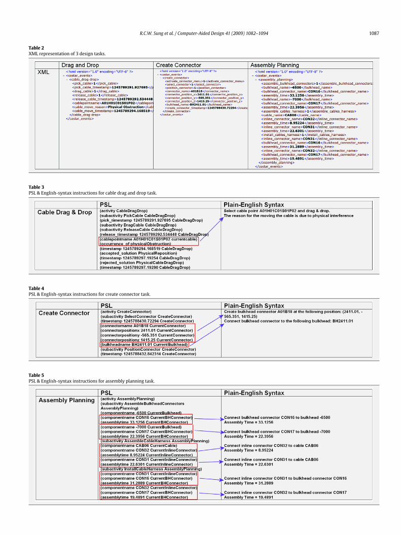
By integrating most of the previous representations into onetable, a storyboard representation is generated, as shown in Fig. 10.Research has shown that this kind of representation has beenbeneficial as a learning aid [38], and it was mentioned that astoryboard ‘‘. . . reduces some of challenge in identifying subproblemsand quantitative information’’ [39].
Fig. 9. DRed graph of assembly planning process.
1090 R.C.W. Sung et al. / Computer-Aided Design 41 (2009) 1082–1094
Fig. 10. Storyboard representation.
In chronological order, this storyboard lists the important oc-currences taking place during a design session, with explicit de-tail presented for each event. In addition to the various knowledgerepresentations presented in the previous sections, the storyboardalso contains video screen grabs of the design session. Note that theprocess of obtaining the video capture is detailed in Section 3.6. Bystudying this storyboard, an engineer can determine the sequenceof events and activities that were carried out, the components thatwere used and the time that each task took to complete. In addi-tion, the outcome of each design decisionmade can be clearly seenand understood. Therefore, as well as a future reference source,
this would also be an ideal training tool because of its explicitnessand simple-to-follow format. Furthermore, all the data in the sto-ryboard has been generated automatically by parsing a log file ob-tained from the user trial into predetermined formats which arethen brought together to generate this output.
3.6. Annotated video captures
As mentioned previously, in addition to the English-syntaxinstructions presented in Section 3.2, another useful trainingaid and knowledge capture format developed takes the form of
R.C.W. Sung et al. / Computer-Aided Design 41 (2009) 1082–1094 1091
Fig. 11. Annotated video captures.
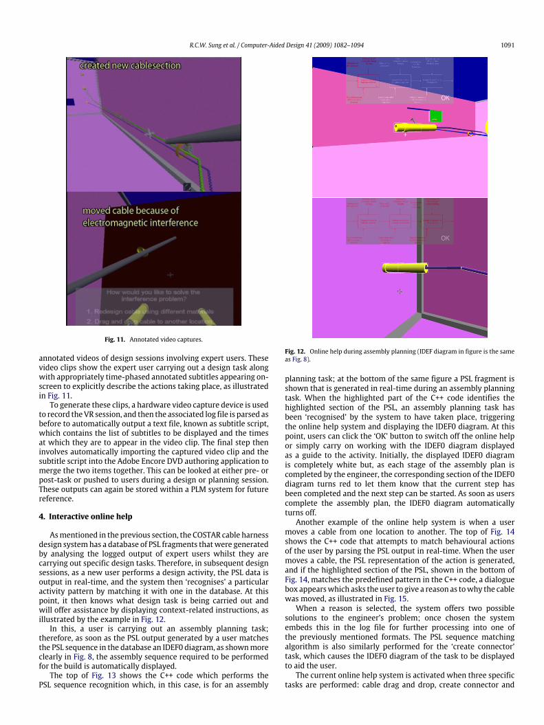
annotated videos of design sessions involving expert users. Thesevideo clips show the expert user carrying out a design task alongwith appropriately time-phased annotated subtitles appearing on-screen to explicitly describe the actions taking place, as illustratedin Fig. 11.To generate these clips, a hardware video capture device is used
to record theVR session, and then the associated log file is parsed asbefore to automatically output a text file, known as subtitle script,which contains the list of subtitles to be displayed and the timesat which they are to appear in the video clip. The final step theninvolves automatically importing the captured video clip and thesubtitle script into the Adobe Encore DVD authoring application tomerge the two items together. This can be looked at either pre- orpost-task or pushed to users during a design or planning session.These outputs can again be stored within a PLM system for futurereference.
4. Interactive online help
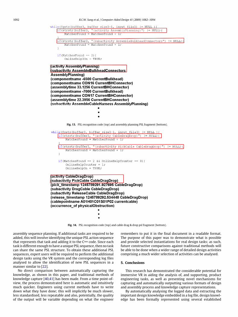
Asmentioned in the previous section, the COSTAR cable harnessdesign systemhas a database of PSL fragments thatwere generatedby analysing the logged output of expert users whilst they arecarrying out specific design tasks. Therefore, in subsequent designsessions, as a new user performs a design activity, the PSL data isoutput in real-time, and the system then ‘recognises’ a particularactivity pattern by matching it with one in the database. At thispoint, it then knows what design task is being carried out andwill offer assistance by displaying context-related instructions, asillustrated by the example in Fig. 12.In this, a user is carrying out an assembly planning task;
therefore, as soon as the PSL output generated by a user matchesthe PSL sequence in the database an IDEF0 diagram, as shownmoreclearly in Fig. 8, the assembly sequence required to be performedfor the build is automatically displayed.The top of Fig. 13 shows the C++ code which performs the
PSL sequence recognition which, in this case, is for an assembly
Fig. 12. Online help during assembly planning (IDEF diagram in figure is the sameas Fig. 8).
planning task; at the bottom of the same figure a PSL fragment isshown that is generated in real-time during an assembly planningtask. When the highlighted part of the C++ code identifies thehighlighted section of the PSL, an assembly planning task hasbeen ‘recognised’ by the system to have taken place, triggeringthe online help system and displaying the IDEF0 diagram. At thispoint, users can click the ‘OK’ button to switch off the online helpor simply carry on working with the IDEF0 diagram displayedas a guide to the activity. Initially, the displayed IDEF0 diagramis completely white but, as each stage of the assembly plan iscompleted by the engineer, the corresponding section of the IDEF0diagram turns red to let them know that the current step hasbeen completed and the next step can be started. As soon as userscomplete the assembly plan, the IDEF0 diagram automaticallyturns off.Another example of the online help system is when a user
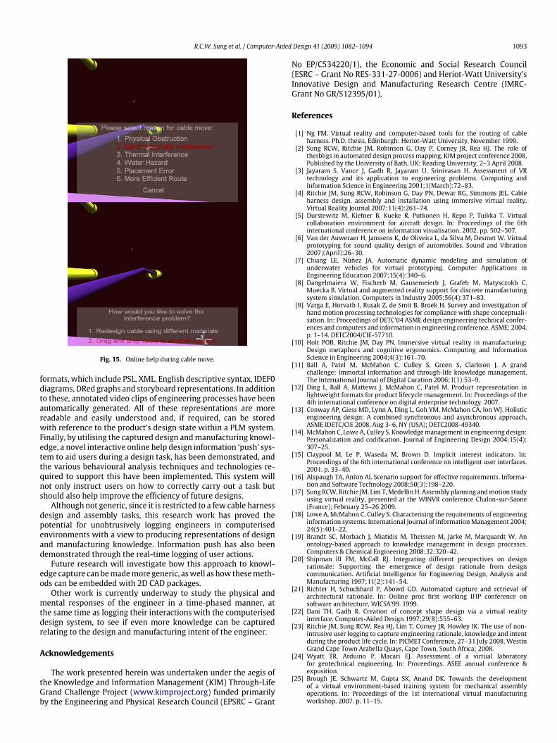
moves a cable from one location to another. The top of Fig. 14shows the C++ code that attempts to match behavioural actionsof the user by parsing the PSL output in real-time. When the usermoves a cable, the PSL representation of the action is generated,and if the highlighted section of the PSL, shown in the bottom ofFig. 14, matches the predefined pattern in the C++ code, a dialoguebox appearswhich asks the user to give a reason as towhy the cablewas moved, as illustrated in Fig. 15.When a reason is selected, the system offers two possible
solutions to the engineer’s problem; once chosen the systemembeds this in the log file for further processing into one ofthe previously mentioned formats. The PSL sequence matchingalgorithm is also similarly performed for the ‘create connector’task, which causes the IDEF0 diagram of the task to be displayedto aid the user.The current online help system is activated when three specific
tasks are performed: cable drag and drop, create connector and
1092 R.C.W. Sung et al. / Computer-Aided Design 41 (2009) 1082–1094
Fig. 13. PSL recognition code (top) and assembly planning PSL fragment (bottom).
Fig. 14. PSL recognition code (top) and cable drag & drop psl fragment (bottom).
assembly sequence planning. If additional tasks are required to beadded, this will involve identifying the unique PSL action sequencethat represents that task and adding it to the C++ code. Since eachtask is different enough tohave aunique PSL sequence, thenno taskcan share the same PSL structure. To obtain these additional PSLsequences, expert users will be required to perform the additionaldesign tasks using the VR system and the corresponding log filesanalysed to allow the identification of new PSL sequences in amanner similar to [22].No direct comparison between automatically capturing the
knowledge, as shown in this paper, and traditional methods ofknowledge capture [40,41] has been made. From a time point-of-view, the process demonstrated here is automatic and intuitivelymuch quicker. Engineers using current methods have to writedown what they have done; this will implicitly be much slower,less standardised, less repeatable and also, potentially, the qualityof the output will be variable depending on what the engineer
remembers to put it in the final document in a readable format.The purpose of this paper was to demonstrate what is possibleand provide selected instantiations for real design tasks; as such,future constructive comparisons against traditional methods willbe able to be done when a wider range of detailed design activitiescomprising a much wider selection of activities can be analysed.
5. Conclusions
This research has demonstrated the considerable potential forimmersive VR in aiding the analysis of, and supporting, productengineering tasks, as well as presenting novel mechanisms forcapturing and automatically outputting various formats of designand assembly process and knowledge capture representations.By automatically analysing the logged data and extracting the
important design knowledge embedded in a log file, design knowl-edge has been formally represented using several established
R.C.W. Sung et al. / Computer-Aided Design 41 (2009) 1082–1094 1093
Fig. 15. Online help during cable move.
formats, which include PSL, XML, English descriptive syntax, IDEF0diagrams, DRed graphs and storyboard representations. In additionto these, annotated video clips of engineering processes have beenautomatically generated. All of these representations are morereadable and easily understood and, if required, can be storedwith reference to the product’s design state within a PLM system.Finally, by utilising the captured design andmanufacturing knowl-edge, a novel interactive online help design information ‘push’ sys-tem to aid users during a design task, has been demonstrated, andthe various behavioural analysis techniques and technologies re-quired to support this have been implemented. This system willnot only instruct users on how to correctly carry out a task butshould also help improve the efficiency of future designs.Although not generic, since it is restricted to a few cable harness
design and assembly tasks, this research work has proved thepotential for unobtrusively logging engineers in computerisedenvironments with a view to producing representations of designand manufacturing knowledge. Information push has also beendemonstrated through the real-time logging of user actions.Future research will investigate how this approach to knowl-
edge capture canbemademore generic, aswell as how thesemeth-ods can be embedded with 2D CAD packages.Other work is currently underway to study the physical and
mental responses of the engineer in a time-phased manner, atthe same time as logging their interactions with the computeriseddesign system, to see if even more knowledge can be capturedrelating to the design and manufacturing intent of the engineer.
Acknowledgements
The work presented herein was undertaken under the aegis ofthe Knowledge and Information Management (KIM) Through-LifeGrand Challenge Project (www.kimproject.org) funded primarilyby the Engineering and Physical Research Council (EPSRC – Grant
No EP/C534220/1), the Economic and Social Research Council(ESRC – Grant No RES-331-27-0006) and Heriot-Watt University’sInnovative Design and Manufacturing Research Centre (IMRC-Grant No GR/S12395/01).
References
[1] Ng FM. Virtual reality and computer-based tools for the routing of cableharness. Ph.D. thesis, Edinburgh: Heriot-Watt University, November 1999.
[2] Sung RCW, Ritchie JM, Robinson G, Day P, Corney JR, Rea HJ. The role oftherbligs in automated design process mapping. KIM project conference 2008,Published by the University of Bath, UK: Reading University. 2–3 April 2008.
[3] Jayaram S, Vance J, Gadh R, Jayaram U, Srinivasan H. Assessment of VRtechnology and its application to engineering problems. Computing andInformation Science in Engineering 2001;1(March):72–83.
[4] Ritchie JM, Sung RCW, Robinson G, Day PN, Dewar RG, Simmons JEL. Cableharness design, assembly and installation using immersive virtual reality.Virtual Reality Journal 2007;11(4):261–74.
[5] Durstewitz M, Kiefner B, Kueke R, Putkonen H, Repo P, Tuikka T. Virtualcollaboration environment for aircraft design. In: Proceedings of the 6thinternational conference on information visualisation. 2002. pp. 502–507.
[6] Van der Auweraer H, Janssens K, de Oliveira L, da Silva M, Desmet W. Virtualprototyping for sound quality design of automobiles. Sound and Vibration2007;(April):26–30.
[7] Chiang LE, Núñez JA. Automatic dynamic modeling and simulation ofunderwater vehicles for virtual prototyping. Computer Applications inEngineering Education 2007;15(4):340–6.
[8] Dangelmaiera W, Fischerb M, Gausemeierb J, Grafeb M, Matysczokb C,Muecka B. Virtual and augmented reality support for discrete manufacturingsystem simulation. Computers in Industry 2005;56(4):371–83.
[9] Varga E, Horvath I, Rusak Z, de Smit B, Broek H. Survey and investigation ofhand motion processing technologies for compliance with shape conceptuali-sation. In: Proceedings of DETC’04 ASME design engineering technical confer-ences and computers and information in engineering conference. ASME; 2004.p. 1–14. DETC2004/CIE-57710.
[10] Holt POB, Ritchie JM, Day PN. Immersive virtual reality in manufacturing:Design metaphors and cognitive ergonomics. Computing and InformationScience in Engineering 2004;4(3):161–70.
[11] Ball A, Patel M, McMahon C, Culley S, Green S, Clarkson J. A grandchallenge: Immortal information and through-life knowledge management.The International Journal of Digital Curation 2006;1(1):53–9.
[12] Ding L, Ball A, Mattews J, McMahon C, Patel M. Product representation inlightweight formats for product lifecycle management. In: Proceedings of the4th international conference on digital enterprise technology. 2007.
[13] Conway AP, Giess MD, Lynn A, Ding L, Goh YM, McMahon CA, Ion WJ. Holisticengineering design: A combined synchronous and asynchronous approach,ASME IDETC/CIE 2008, Aug 3–6, NY (USA); DETC2008-49340.
[14] McMahon C, Lowe A, Culley S. Knowledgemanagement in engineering design:Personalization and codification. Journal of Engineering Design 2004;15(4):307–25.
[15] Claypool M, Le P, Waseda M, Brown D. Implicit interest indicators. In:Proceedings of the 6th international conference on intelligent user interfaces.2001. p. 33–40.
[16] Alspaugh TA, Anton AI. Scenario support for effective requirements. Informa-tion and Software Technology 2008;50(3):198–220.
[17] Sung RCW, Ritchie JM, Lim T,Medellin H. Assembly planning andmotion studyusing virtual reality, presented at the WINVR conference Chalon-sur-Saone(France); February 25–26 2009.
[18] Lowe A, McMahon C, Culley S. Characterising the requirements of engineeringinformation systems. International Journal of InformationManagement 2004;24(5):401–22.
[19] Brandt SC, Morbach J, Miatidis M, Theissen M, Jarke M, Marquardt W. Anontology-based approach to knowledge management in design processes.Computers & Chemical Engineering 2008;32:320–42.
[20] Shipman III FM, McCall RJ. Integrating different perspectives on designrationale: Supporting the emergence of design rationale from designcommunication. Artificial Intelligence for Engineering Design, Analysis andManufacturing 1997;11(2):141–54.
[21] Richter H, Schuchhard P, Abowd GD. Automated capture and retrieval ofarchitectural rationale. In: Online proc first working IFIP conference onsoftware architecture, WICSA’99. 1999.
[22] Dani TH, Gadh R. Creation of concept shape design via a virtual realityinterface. Computer-Aided Design 1997;29(8):555–63.
[23] Ritchie JM, Sung RCW, Rea HJ, Lim T, Corney JR, Howley IK. The use of non-intrusive user logging to capture engineering rationale, knowledge and intentduring the product life cycle. In: PICMET Conference, 27–31 July 2008, WestinGrand Cape Town Arabella Quays, Cape Town, South Africa; 2008.
[24] Wyatt TR, Arduino P, Macari EJ. Assessment of a virtual laboratoryfor geotechnical engineering. In: Proceedings. ASEE annual conference &exposition.
[25] Brough JE, Schwartz M, Gupta SK, Anand DK. Towards the developmentof a virtual environment-based training system for mechanical assemblyoperations. In: Proceedings of the 1st international virtual manufacturingworkshop. 2007. p. 11–15.

1094 R.C.W. Sung et al. / Computer-Aided Design 41 (2009) 1082–1094
[26] Schwartz M, Gupta SK, Anand DK, Kavetsky R. Virtual Mentor: A step towardsproactive user monitoring and assistance during virtual environment-basedtraining. In: Performance metrics for intelligent systems (PerMIS) workshop,Gaithersburg (MD); August 2007.
[27] Dey AK, Hamid R, Beckmann C, Li I, Hsu D. A CAPpella: Programming bydemonstration of context-aware applications. In: CHI2004 conference onhuman factors in computer systems, Vienna; 24–29 April 2004. p. 33–40.
[28] Jin Y, Ishino Y. DAKA: Design activity knowledge acquisition through data-mining. International Journal of Production Research 2006;44(14):2813–37.
[29] Ng FM, Ritchie JM, Simmons JEL, Dewar RG. Designing cable harnessassemblies in virtual environments. Materials Processing Technology 2000;107(1):37–43.
[30] Caudell TP, Mizell DW. Augmented reality: An application of heads-up displaytechnology to manual manufacturing processes. In: IEEE hawaii internationalconference on system sciences. 1992. p. 659–669.
[31] Ritchie JM, Simmons JEL, Holt POB, Russell GT. Immersive virtual realityas an interactive tool for cable harness design. In: PRASIC 2002, UniversityTransylvania of Brasov, Romania, on November 2002.
[32] Robinson G, Ritchie JM, Day PN, Dewar RG. System design and user evaluationof Co-Star: An immersive stereoscopic system for cable harness design.Computer-Aided Design 2007;39(4):245–57.
[33] Gruninger M, Bock C. PSL: A semantic domain for flow models. SoftwareSystems Modeling 2005;4:209–31.
[34] Extensible Markup Language: http://www.w3.org/XML/ (Last viewed on Dec.11th 2008).
[35] Integrated Definition Methods: http://www.idef.com/ (Last viewed on Dec.9th 2008).
[36] Kim S, Bracewell RH, Wallace KM. From discourse analysis to answeringdesign questions. In: International workshop on the application of languageand semantic technologies to support knowledge management processes.Whittlebury (UK); October 2004.
[37] Knowledge Interchange Format: http://www-ksl.stanford.edu/knowledge-sharing/kif/ (Last viewed on Mar. 19th 2009).
[38] Knauf R, Sakurai Y, Dohi S, Tsuruta S, Gonzalez A. Toward making didacticsa subject of knowledge engineering, In: 7th IEEE international conference onadvanced learning technologies Nigata: Japan. 2007. p. 788–792.
[39] Barron B. Problem solving in video-based microworlds: Collaborative andindividual outcomes of high-achieving sixth-grade students. Journal ofEducational Psychology 2000;92(2):391–8.
[40] Kwong E, Lee WB. Knowledge elicitation in reliability management in theairline industry. Journal of Knowledge Management 2009;13(2):35–48.
[41] McAdam R, O’Hare T, Moffett S. Collaborative knowledge sharing in compositenew product development: An aerospace study. Technovation 2008;28:245–56.
Recommended