TM
Freescale Semiconductor Proprietary Information. Freescale™ and the Freescale logo are trademarksof Freescale Semiconductor, Inc. All other product or service names are the property of their respective owners. © Freescale Semiconductor, Inc. 2008.
PM104
LTE: Downlink Physical-Layer Overview and Throughput Simulation Results
Nov 5, 2008
Ian C. Wong, Ph.D. Jason WongSystems Engineer, Algorithms and Standards System & Application EngineerCellular Products Group R&D GSM

TMFreescale Semiconductor Proprietary Information. Freescale™ and the Freescale logo are trademarksof Freescale Semiconductor, Inc. All other product or service names are the property of their respective owners. © Freescale Semiconductor, Inc. 2008. 2
Agenda
►Overview of LTE• LTE philosophy• LTE performance requirements
►LTE Physical Layer • General description• Physical channels• Channel coding• Modulation
►Throughput simulation results• Freescale’s LTE downlink simulator• Downlink shared channel• Control channel

TMFreescale Semiconductor Proprietary Information. Freescale™ and the Freescale logo are trademarksof Freescale Semiconductor, Inc. All other product or service names are the property of their respective owners. © Freescale Semiconductor, Inc. 2008. 3
3GPP – LTE Philosophy and Criteria
►Philosophy• LTE focus is on:
Enhancement of the Universal Terrestrial Radio Access (UTRA)Optimization of the UTRAN architecture
• With HSPA (downlink and uplink), UTRA will remain highly competitive for several years
• LTE project aims to ensure the continued competitiveness of the 3GPP technologies for the future
►Criteria• Demand for higher data rates• Expectations of additional 3G spectrum allocations• Greater flexibility in frequency allocations• Continued cost reduction• Keeping up with other (unlicensed) technologies (eg WiMAX)

TMFreescale Semiconductor Proprietary Information. Freescale™ and the Freescale logo are trademarksof Freescale Semiconductor, Inc. All other product or service names are the property of their respective owners. © Freescale Semiconductor, Inc. 2008. 4
Performance Requirements for LTE Category Requirement
Peak data rate DL: 100 Mbps in 20 MHz BW (5 bps/Hz)UL: 50 Mbps in 20 MHz BW (2.5 bps/Hz)
Control-plane latency < 100 ms for Idle to Active mode transition
Control-plane capacity > 200 users per cell in Active state within 5 MHz
User-plane latency < 5 ms for 1 user with 1 data stream and small IP packet
Average user throughput DL: 3-4 times of HSDPA per MHzUL: 2-3 of HSUPA per MHz
MobilityOptimized for 0-15 km/h
Support with high performance for 15-120 km/hSupport for 120-350 km/h or even 500 km/h
CoverageAll targets met for 5 km cells
Slight degradation for 5-30 km cellsSupport for 30-100 km cells
Spectrum flexibility Support for 1.25 – 20 MHz BandwidthsPaired or unpaired spectrum allocations

TMFreescale Semiconductor Proprietary Information. Freescale™ and the Freescale logo are trademarksof Freescale Semiconductor, Inc. All other product or service names are the property of their respective owners. © Freescale Semiconductor, Inc. 2008. 5
LTE Protocol Architecture Around the Physical Layer
►PHY interfaces MAC sub-layer of Layer 2 and RRC of Layer 3
►PHY offers a transport channel to MAC
• Transport channel characterized by how information is transferred
►MAC offers logical channels to the RLC
• Logical channel characterized by the type of information transferred.
Radio Resource Control (RRC)
Medium Access Control (MAC)
Physical Layer(PHY)
Logical channels
Transport channels
Con
trol/M
easu
rem
ents Layer 2
Layer 1
Layer 3
Radio Link Control (RLC)
…
Physical channels
TMFreescale Semiconductor Proprietary Information. Freescale™ and the Freescale logo are trademarksof Freescale Semiconductor, Inc. All other product or service names are the property of their respective owners. © Freescale Semiconductor, Inc. 2008. 6
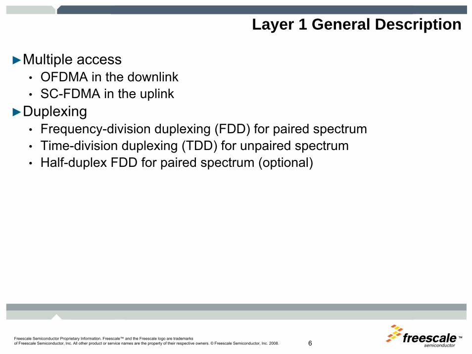
Layer 1 General Description
►Multiple access• OFDMA in the downlink• SC-FDMA in the uplink
►Duplexing• Frequency-division duplexing (FDD) for paired spectrum• Time-division duplexing (TDD) for unpaired spectrum• Half-duplex FDD for paired spectrum (optional)

TMFreescale Semiconductor Proprietary Information. Freescale™ and the Freescale logo are trademarksof Freescale Semiconductor, Inc. All other product or service names are the property of their respective owners. © Freescale Semiconductor, Inc. 2008. 7
Frame Structure
►Frame structure type 1 applicable to FDD and half duplex FDD►Each 10 ms radio frame is divided into ten equally sized sub-frames►Each sub-frame consists of two equally sized slots
Slot 0 Slot 1 Slot 2 Slot 3 … Slot 18 Slot 19
One radio frame = 10 ms
One subframe = 1 ms
One slot = 0.5 ms

TMFreescale Semiconductor Proprietary Information. Freescale™ and the Freescale logo are trademarksof Freescale Semiconductor, Inc. All other product or service names are the property of their respective owners. © Freescale Semiconductor, Inc. 2008. 8
Slot Structure and Resource Elements
DLsymbN
slotT
0=l 1DLsymb −= Nl
RB scDL RB
NN
× RB scN
RBsc
DLsymb NN ×
),( lk
0=k
1RBsc
DLRB −= NNk
Transmission BW (MHz) 1.4 3 5 10 15 20
Slot duration 0.5 ms
Subcarrier spacing 15 kHz / 7.5 kHz (MBSFN)
Sampling frequency (MHz)
1.92 3.84 7.68 15.36 23.04 30.72
FFT size 128 256 512 1024 1536 2048
# downlink RBs(NDL
RB)6 15 25 50 75 100
# subarriers / RB (NRB
sc)12 / 24 (MBSFN)
# OFDM symbols / slot (NDL
symb)
7 (normal CP) 6 (extended CP)
3 (extended CP in MBSFN)
CP length (μs) 1 x 5.21, 6 x 4.69 (normal)16.6 (extended)

TMFreescale Semiconductor Proprietary Information. Freescale™ and the Freescale logo are trademarksof Freescale Semiconductor, Inc. All other product or service names are the property of their respective owners. © Freescale Semiconductor, Inc. 2008. 9
Downlink Physical Channels
►Physical downlink shared channel (PDSCH)• Carries the downlink shared channel (DL-SCH) and paging channel (PCH)
►Physical downlink control channel (PDCCH)• Informs the UE about the resource allocation of PCH and DL-SCH, and Hybrid
ARQ information related to DL-SCH• Carries the uplink scheduling grant
►Physical control format indicator channel (PCFICH)• Informs the UE about the number of OFDM symbols used for the PDCCHs;• Transmitted in every subframe.
►Physical broadcast channel (PBCH)• The coded broadcast channel (BCH) transport block is mapped to four
subframes within a 40 ms interval• 40 ms timing is blindly detected• Each subframe is assumed to be self-decodable, i.e. the BCH can be decoded
from a single reception, assuming sufficiently good channel conditions.►Physical Hybrid ARQ Indicator Channel (PHICH)
• Carries Hybrid ARQ ACK/NAKs in response to uplink transmissions.►Physical multicast channel (PMCH)
• Carries the multicast channel (MCH) transport channel

TMFreescale Semiconductor Proprietary Information. Freescale™ and the Freescale logo are trademarksof Freescale Semiconductor, Inc. All other product or service names are the property of their respective owners. © Freescale Semiconductor, Inc. 2008. 10
Channel Coding of Physical Channels
►Cyclic redundancy check• Error detection capability for transport block and each code block
►Code-block segmentation• Segment the transport block into smaller code blocks of roughly equal length
►Channel coding• Rate 1/3 turbo code – Downlink shared, paging, and multicast channels• Rate 1/3 tail-biting convolutional code – Broadcast channel and downlink control
information• Rate 1/16 block code – Control format indicator• Rate 1/3 repetition code – HARQ indicator
►Rate-matching• Includes sub-block interleaving, bit collection, and bit selection and pruning• Support hybrid ARQ transmissions
CRC
Code block
segment-ation
Channelcoding
Ratematching
UncodedTransport Channel bits
CodedPhysicalChannel bits

TMFreescale Semiconductor Proprietary Information. Freescale™ and the Freescale logo are trademarksof Freescale Semiconductor, Inc. All other product or service names are the property of their respective owners. © Freescale Semiconductor, Inc. 2008. 11
Baseband Modulation of Downlink Physical Channels
►Scrambler breaks long strings of 1s and 0s of the coded bits►Modulation mapper converts scrambled bits into complex-valued symbols►Layer mapper and precoder performs symbol transformations to enable
multi-antenna transmission techniques►Resource element mapper maps the physical channel symbols to the
appropriate locations in the time-frequency grid ►OFDM signal generation converts the frequency domain symbols to time
domain complex baseband signals for each antenna port for transmission
ScramblerOFDM Signal
Generation
ModulationMapper
LayerMapper
+Precoder
ResourceElementMapper
Reference Signal Synchronization Signal
Reference & synch signalgenerator
Coded PhysicalChannel bits Complex
OFDM signal
TMFreescale Semiconductor Proprietary Information. Freescale™ and the Freescale logo are trademarksof Freescale Semiconductor, Inc. All other product or service names are the property of their respective owners. © Freescale Semiconductor, Inc. 2008. 12
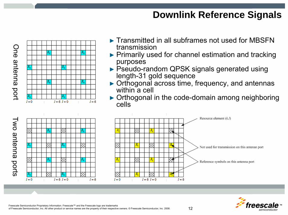
Downlink Reference Signals
► Transmitted in all subframes not used for MBSFN transmission
► Primarily used for channel estimation and tracking purposes
► Pseudo-random QPSK signals generated using length-31 gold sequence
► Orthogonal across time, frequency, and antennas within a cell
► Orthogonal in the code-domain among neighboring cells
One antenna port
Two antenna ports

TMFreescale Semiconductor Proprietary Information. Freescale™ and the Freescale logo are trademarksof Freescale Semiconductor, Inc. All other product or service names are the property of their respective owners. © Freescale Semiconductor, Inc. 2008. 13
Downlink Synchronization Signals
►Primary synch signal• Half-frame timing reference• Frequency domain Zadoff-Chu
sequence• Occupies only middle 62
subcarriers in frequency►Secondary synch signal
• Frame timing reference• Interleaved concatenation of two
length-31 m-sequences
DL - RS
PSCH
1st SSCH
2nd SSCH
RS: Reference SignalPSCH: Primary Synchronization ChannelSSCH: Secondary Synchronization Channel
Frame (10ms)
Subframe(1ms)
1 2 3 4 5 6 7 1 2 3 4 5 6 7 1 2 3 4 5 6 7 1 2 3 4 5 6 7 1 2 3 4 5 6 7 1 2 3 4 5 6 7 1 2 3 4 5 6 7 1 2 3 4 5 6 7
Slot(0.5ms)
Slot 0 Slot 10
* Figure courtesy of Taeyoon Kim, Freescale

TMFreescale Semiconductor Proprietary Information. Freescale™ and the Freescale logo are trademarksof Freescale Semiconductor, Inc. All other product or service names are the property of their respective owners. © Freescale Semiconductor, Inc. 2008. 14
Freescale’s Radio Link Simulator Architecture
PHY EncoderTS 36.212 –
Multiplexing and Channel Coding
Transportchannel raw bits
(generated by encoder) …
Physical channel coded bits
PHY ModulatorTS 36.211 –
Physical Channels and Modulation
PDSCHPDCCH
PBCH
TD-transmitted signal
Mobile MIMOChannel
PHY DemodulatorTS 36.211 –
Physical Channels and Modulation
Noise/Interference…
PDSCHPDCCH
PBCH
PHY DecoderTS 36.212 –
Multiplexing and Channel Coding
Decoded bits
Physical channel LLRs
Statistics Calculator (Coded/Uncoded BER, PER, Throughput)
PhyChanBits.txTrChanBits.tx
TrChanBits.rx PhyChanBits.rx
ReceiverImpairments

TMFreescale Semiconductor Proprietary Information. Freescale™ and the Freescale logo are trademarksof Freescale Semiconductor, Inc. All other product or service names are the property of their respective owners. © Freescale Semiconductor, Inc. 2008. 15
Example RAN4 PDSCH Simulation Results
FDD 1x2 SIMO, 10MHz, 16-QAM 1/2, ETU300 channel
SIMO 16QAM 1/2 ETU300
0
2000000
4000000
6000000
8000000
10000000
12000000
14000000
16000000
-8 -6 -4 -2 0 2 4 6 8 10 12 14
SNR (dB)
Thro
ughp
ut (b
ps)
EricssonFreescaleInterDigitalLGEFujitsuNokiaNXPMotorolaNECTI

TMFreescale Semiconductor Proprietary Information. Freescale™ and the Freescale logo are trademarksof Freescale Semiconductor, Inc. All other product or service names are the property of their respective owners. © Freescale Semiconductor, Inc. 2008. 16
Example RAN 4 PDSCH Simulation Results
►FDD 2x2-SFBC, 10MHz, ►1 codeword, 2 layers►16-QAM rate 1/2►EVA5, non-ideal channel
estimation
►FDD 2x2-SM with precoderfeedback for whole BW,
►10MHz MMSE receiver ►2 x 64QAM 3/4, ►EVA5, non-ideal channel
estimation
MIMO-SFBC 16QAM 1/2 EVA5
0
2000000
4000000
6000000
8000000
10000000
12000000
14000000
-8 -6 -4 -2 0 2 4 6 8 10 12 14 16
SNR (dB)
Thro
ughp
ut (b
ps)
EricssonFreescaleInterDigitalLGEFujitsuNokiaNXPMotorolaNECTI
MIMO-SM 64QAM 1/3 EPA5
0
10000000
20000000
30000000
40000000
50000000
60000000
70000000
2 4 6 8 10 12 14 16 18 20 22 24 26 28 30 32
SNR (dB)
Thro
ughp
ut (b
ps)
Ericsson
Freescale
InterDigital
LGE
Fujitsu
Nokia
NXP
Motorola
NEC
TI

TMFreescale Semiconductor Proprietary Information. Freescale™ and the Freescale logo are trademarksof Freescale Semiconductor, Inc. All other product or service names are the property of their respective owners. © Freescale Semiconductor, Inc. 2008. 17
Example RAN4 PDCCH/PCFICH Simulations
0.10%
1.00%
10.00%
100.00%
-10 -8 -6 -4 -2 0 2 4 6
SNR [dB]PC
FIC
H/P
DC
CH
BLE
R
Ericsson
Freescale
TI
LGE
NTT DoCoMo
Motorola
Marvell
Nokia
Fujitsu
InterDigital
NEC
CATT
Qualcomm
AVERAGE
Sim 46.6: FDD 1x2 10MHz 8CCE Format1 ETU70 low
0.10%
1.00%
10.00%
100.00%
-10 -8 -6 -4 -2 0 2 4 6
SNR [dB]
PCFI
CH
/PD
CC
HB
LER
Ericsson
Freescale
TI
LGE
NTT DoCoMo
Motorola
Marvell
Nokia
Fujitsu
InterDigital
NEC
CATT
Qualcomm
Samsung
AVERAGE
Sim 47.10: FDD 2x2 SFBC 1.4MHz 2CCE Format2 EPA5 low

TMFreescale Semiconductor Proprietary Information. Freescale™ and the Freescale logo are trademarksof Freescale Semiconductor, Inc. All other product or service names are the property of their respective owners. © Freescale Semiconductor, Inc. 2008. 18
References
►[1] Francois Coureau, “3GPP Evolution: LTE and SAE,” Beijing, China, 2004
►[2] TR 25.913 7.3.0, “Requirements for Evolved-UTRA and Evolved UTRAN,” March 2006
►[3] TS 36.201 v. 8.1.0, “E-UTRA: LTE Physical Layer – General Description,” Nov. 2007
►[4] TS 36.211 v. 8.2.0, “E-UTRA: Physical Channels and Modulation,” March 2008
►[5] TS 36.212 v. 8.2.0, “E-UTRA: Multiplexing and Channel Coding,”March 2008
►[6] TS 36.300 v. 8.4.0, “E-UTRA and E-UTRAN: Overall Description Stage 2,” March 2008

TMFreescale Semiconductor Proprietary Information. Freescale™ and the Freescale logo are trademarksof Freescale Semiconductor, Inc. All other product or service names are the property of their respective owners. © Freescale Semiconductor, Inc. 2008. 19
Related Session Resources
SessionsSession ID
DemosPedestal ID
PM101 LTE: MIMO Techniques in 3GPP-LTE
Title
Demo Title
Session Location – Online Literature Libraryhttp://www.freescale.com/webapp/sps/site/homepage.jsp?nodeId=052577903644CB

TM
Recommended


![Deploymentofanaerialplatformsystemforrapid ......ground, the balloon’s coverage area is 47.39 km2 with a constant 54 Mb/s downlink throughput,butascoverageincreasesto72km 2 throughputfluctuates.In[20]authors](https://img.dokumen.tips/doc/110x75/6049821a1a0d4a44016cf4e4/deploymentofanaerialplatformsystemforrapid-ground-the-balloonas-coverage.jpg)