ALGORITHMS AND ARCHITECTURES FOR
DISCRETE WAVELET TRANSFORM BASED
VIDEO ENCODER
Thesis Submitted in partial fulfillment for the
Award of Degree
DOCTOR OF PHILOSOPHY
in
Electrical and Electronics Engineering
by
SHRIRAM PARAMESHWAR HEGDE
VINAYAKA MISSIONS UNIVERSITY SALEM, TAMILNADU, INDIA
DECEMBER 2015
VINAYAKA MISSIONS UNIVERSITY
Declaration
I, Shriram Parameshwar Hegdedeclare that the thesis entitled
“Algorithms and Architectures for Discrete Wavelet Transform Based
Video Encoder’’ submitted by me for the Degree of Doctor of Philosophy
is the record of work carried out by me during the period
from January 2008 to December 2015 under the guidance of
Dr S. Ramachandran and has not formed the basis for the award of any
degree, diploma, associate ship, fellowship, titles in this or any other
University or other similar institutions of higher learning.
(SHRIRAM PARAMESHWAR HEGDE)
Place: Bangalore
Date: 21-06-2016
VINAYAKA MISSIONS UNIVERSITY
Certificate by the Guide
I, Dr S. Ramachandran certify that the thesis entitled
“Algorithms and Architectures for Discrete Wavelet
Transform based Video Encoder” submitted for the Degree
Doctor of Philosophy by Mr. Shriram Parameshwar Hegde. The
record of research work carried out by him during the period from
January 2008 to December 2015 under my guidance and supervision
and this work has not formed the basis for the award of any degree,
diploma, associate-ship, fellowship or other titles in this University
or any other university or Institution of higher learning.
(Dr. S. Ramachandran)
Place: Bangalore
Date:21-06-2016

i
ACKNOWLEDGEMENTS
I would like to express my heartfelt thanks to the Chancellor
and Dean (Research) of Vinayaka Missions University, Salem for
their constant support and encouragement.
I would like to express my heartfelt thanks to my Guide
Dr S. Ramachandran for continuous and efficient mentoring. I would
like to thank him for encouraging my research and for allowing me to
grow as a researcher. His advice on both research as well as on my
career has been priceless.
A special thanks to Almighty and my family members. Words
cannot express how grateful I am to all for their sacrifices made on my
behalf. I would also like to thank all my friends and well-wishers who
supported me and motivated me to strive towards my goal.
I thank the Management, Principal, and my fellow colleagues at
SDMIT, UJIRE and I feel fortunate to have used the R&D facilities of
SJBIT, Bangalore and executing this work in such a rich intellectual
climate comprising many brilliant Professionals. My special thanks are
due to Mr Shailesh who had been a great source of Inspiration and
Technical help, without whom this work could not have been completed
to perfection.
Shriram Parameshwar Hegde
ii
ABSTRACT
Image compression is of incredible significance in multimedia
frameworks and applications on the grounds that it radically decreases
bandwidth necessities for transmission and memory prerequisites for
capacity. Albeit prior gauges for image compression were taking into
account the Discrete Cosine Transform. Of late, Discrete Wavelet
Transform has been observed to be more proficient for image coding than
the DCT.
In spite of enhancements in compression proficiency, wavelet image
coders altogether expand memory utilization and many-sided quality when
contrasted to DCT-based coders. A noteworthy explanation behind the
high memory necessities is that the algorithm to wavelet transform requires
the whole image to be in memory. Albeit a few proposition lessen the
memory utilization, they show issues that thwart their implementation.
Moreover, some wavelet image coders as SPIHT (which has turned into a
benchmark for wavelet coding), constantly need to hold the whole image in
memory. SPIHT can be considered very perplexing on the grounds that it
performs bit-plane coding with different image checks.
iii
In this work, we intend to diminish memory use and unpredictability
in wavelet-based image and feature coding, while protecting pressure
effectiveness. To this end, a 5/3 2D-DWT technique for the implementation
has been realized to pack digital image for lessening the equipment
prerequisite. Likewise, a novel SPIHT algorithm alongside DWT has also
been realized for the image compression to lessen the space necessity
and postponement time. At long last, a construction modeling for the
feature compression utilizing DWT is introduced, which is perfect for the
ongoing execution.
iv
LIST OF ABBREVIATIONS
MPEG Moving Picture Experts Group JPEG Joint Photographic Experts Group
SPIHT Set Partitioning in Hierarchical Trees ISPIHT Inverse Set Partitioning in Hierarchical Trees ROI Region of Interest DCT Discrete Cosine Transform DWT Discrete Wavelet Transform IDWT Inverse Discrete Wavelet Transform WT Wavelet Transform CWT Continuous Wavelet Transform LIS List of Insignificant Sets LIP List of Insignificant Pixels LSP List of Significant Pixels PSNR Peak Signal to Noise Ratio MSE Mean SquaredError CR Compression Ratio FPGA Field Programmable Gate Array CODEC Compression/Decompression MATLAB Matrix Laboratory PNG Portable Network Graphics CALIC Context Based Adaptive Loss Less Image Codec
GIF Graphic Interchange Format STFT Short Time Fourier Transform CDF Cohen-Daubechies-Feauveau EZT Embedded Zero Tree WCQT Wavelet Coded Quantization Transform VM Verification Model EBCOT Embedded Block Coding With Optimal Truncation
RCT Reversible Colour Transform SIPO Serial In Parallel Out
PISO Parallel In Serial Out
VLSI Very Large Scale Integration
BP Bit Parallel
OBMC Over Lapping Block Motion Compensation
v
EEWITA Energy Efficient Wavelet Image TransformAlgorithm
SDVC Scalable Distributed Video Coding
AVC Advanced Video Coding
JSVM Joint Scalable Video Model
BMA British Medical Association
BMME Block Matching Motion Estimation
TSS Three Step Search
FSS Four Step Search
NTSS New Three Step Search
BBGDS Block Based GradientDescent Search
DS Diamond Search
CDS Cross Diamond Search
VCL Video Coding Layer
ITU International Telecommunication Union
VCEG Video Coding Expert Group
ISO/IEC International Organisation for Standardization/International Electro -Technical Commission
SOM Self Organizing Map
BPC Bit Plane Coder
EDP Exchange DeliveryPoint
APT Automatic Picture Transmission
SAR Storage Aspect Ratio
ETS Error Tolerance Scheme
KLT Karhunen - Loeve Transform
BWFBs Bi orthogonal Wavelet Filter Banks
FIFO First In First Out
EZW Embedded Zero Wavelet
PIT Progressive Image Transmission
VHDL Very high speed integrated circuit hardware description language
HDTV High Definition Television
NTSC National Television Sytem(s) Committee
PAL Phase Alternation Line
SECAM Sequential Colour And Memory
FIR First Information Report
ASCII American Standard Code for Information Interchange
vi
LIST OF FIGURES
Figure
No
Figure Name Page
No
1.1
1.2
1.
Basic flow of Image Compression Technique
Example of Mother Wavelet
2
1.2 Example of Mother Wavelet 11
1.3 Example of Scaled Baby Wavelet 11
1.4 Example of Translated Baby Wavelet
12
1.5 Dyadic Sampling
16
1.6 Subband Decomposition without Scaling Function
16
1.7 Subband Decomposition with Scaling Function 17
1.8 Haar Family Wavelet 17
1.9 DWT Analysis of Signal using Two-Channel Subband
Coding
17
1.10
Multiple Level DWT Analysis of Signal using Two-Channel subband coding
18
vii
Figure
No
Figure Name Page
No
1.11 DWT Synthesis of Signal using Two-Channel Subband
Coding
18
1.12 CDF 5/3 analysis Wavelet 20
1.13 CDF 5/3 Synthesis Wavelet 21
1.14 CDF 7/9 analysis Wavelet 22
1.15 CDF 7/9Synthesis Wavelet 22
1.16 JPEG2000 block diagram
25
3.1 Result of Three Level 2D Wavelet Transform Operation on an Image
76
3.2 DWT Analysis and Synthesis Coding
79
3.3 The 2D-DWT analysis filter bank 80
3.4 Proposed 1D-DWT Architecture 84
3.5 Proposed 2D-DWT Architecture 85
3.6 Image Output of 1D-DWT Block 87
3.7 Image Output of 2D-DWT Block 88
3.8 RTL View of 1D-DWT Block 89
3.9 RTL View of 2D-DWT Block 90
3.10 Comparison of No. of Slice Registers in 1D-DWT
Architecture
91
3.11 Comparison of No. of Flip Flops in 1D-DWT Architecture 92
3.12 Comparison of No. of Multipliers in 1D-DWT Architecture 92
viii
Figure
No
Figure Name Page
No
3.13 Comparison of Frequency (MHz) in 1D-DWT Architecture 93
3.14 Comparison of No. of Slice Registers in 2D-DWT
Architecture
94
3.15 Comparison of No. of Flip Flops in 2D-DWT Architecture 95
3.16 Comparison of Frequency in 2D-DWT Architecture 95
3.17 Comparison of Components used in 2D-DWT
Architectures
96
4.1 Block Diagram of an Image Codec as Realized 101
4.2 Wavelet Coder 106
4.3 Wavelet Decoder 106
4.4 Frequency distribution of DWT 107
4.5 Process flow of SPIHT algorithm 110
4.6 Image Quality Variation using SPIHT 110
4.7 Optimized Embedded Coding 119
4.8(a) Flow Diagram of SPIHT Algorithm 122
4.8(b) Flow Chart of SPIHT Algorithm 123
4.9 Tree Structure of SPIHT 123
4.10 Sorting Pass 125
4.11 SPIHT Refinement PASS 126
4.12 Original Image for Wavelet Transform 133
ix
Figure
No
Figure Name Page
No
4.13 Pyramid tree generated by two way Decomposition 133
4.14 Recovered images after encoding and Decoding 134
4.15 Comparison of MSE(Graphical analysis) 134
4.16 Comparison of Execution Time( Graphical analysis) 135
4.17 Reconstruction of Lena image 136
5.1 Video coding and decoding process 141
5.2 Decomposition of image frame from level 1 to 3 143
5.3 Discrete-Wavelet Transform 150
5.4 Inverse Discrete-Wavelet Transform 151
5.5 Block diagram of a wavelet based video Encoder 152
5.6 Schemetic 2D wavelet transform function 153
5.7 Wavelet transformed image 154
5.8 Schematic of the Encoder 159
5.9 Decimation Filter Output 160
5.10 Wavelet Filter Output 161
5.11 Real Numbers to Binary Conversion 161
5.12 Arithmetic Coder Output 162
x
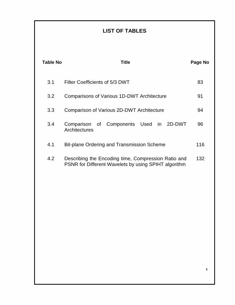
LIST OF TABLES
Table No Title Page No
3.1 Filter Coefficients of 5/3 DWT 83
3.2 Comparisons of Various 1D-DWT Architecture 91
3.3 Comparison of Various 2D-DWT Architecture 94
3.4 Comparison of Components Used in 2D-DWT Architectures
96
4.1 Bit-plane Ordering and Transmission Scheme 116
4.2 Describing the Encoding time, Compression Ratio and PSNR for Different Wavelets by using SPIHT algorithm
132
xi
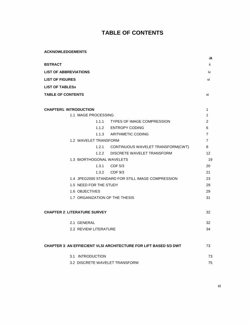
TABLE OF CONTENTS
ACKNOWLEDGEMENTS
iA
BSTRACT ii
LIST OF ABBREVIATIONS iv
LIST OF FIGURES vi
LIST OF TABLESx
TABLE OF CONTENTS xi
CHAPTER1: INTRODUCTION 1
1.1 MAGE PROCESSING 1
1.1.1 TYPES OF IMAGE COMPRESSION 2
1.1.2 ENTROPY CODING 6
1.1.3 ARITHMETIC CODING 7
1.2 WAVELET TRANSFORM 7
1.2.1 CONTINUOUS WAVELET TRANSFORM(CWT) 8
1.2.2 DISCRETE WAVELET TRANSFORM 12
1.3 BIORTHOGONAL WAVELETS 19
1.3.1 CDF 5/3 20
1.3.2 CDF 9/3 21
1.4 JPEG2000 STANDARD FOR STILL IMAGE COMPRESSION 23
1.5 NEED FOR THE STUDY 29
1.6 OBJECTIVES 29
1.7 ORGANIZATION OF THE THESIS 31
CHAPTER 2: LITERATURE SURVEY 32
2.1 GENERAL 32
2.2 REVIEW LITERATURE 34
CHAPTER 3: AN EFFIECIENT VLSI ARCHITECTURE FOR LIFT BASED 5/3 DWT 73
3.1 INTRODUCTION 73
3.2 DISCRETE WAVELET TRANSFORM 75
xii
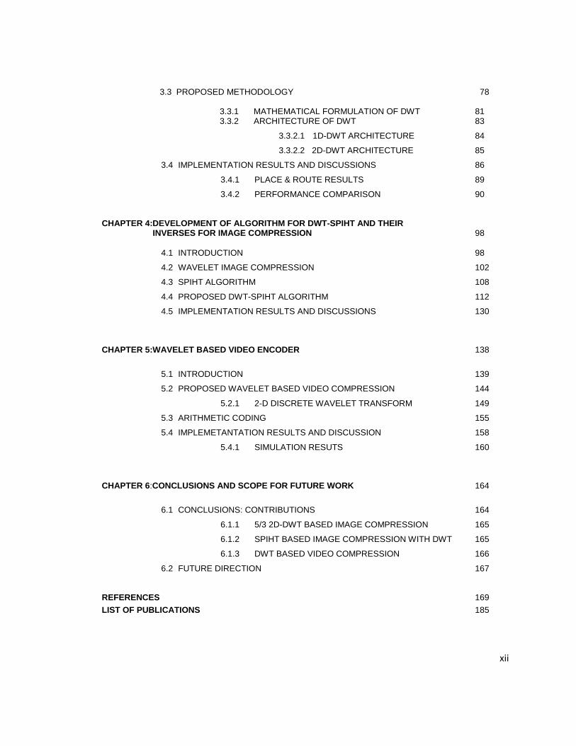
3.3 PROPOSED METHODOLOGY 78
3.3.1 MATHEMATICAL FORMULATION OF DWT 81 3.3.2 ARCHITECTURE OF DWT 83
3.3.2.1 1D-DWT ARCHITECTURE 84
3.3.2.2 2D-DWT ARCHITECTURE 85
3.4 IMPLEMENTATION RESULTS AND DISCUSSIONS 86
3.4.1 PLACE & ROUTE RESULTS 89
3.4.2 PERFORMANCE COMPARISON 90
CHAPTER 4:DEVELOPMENT OF ALGORITHM FOR DWT-SPIHT AND THEIR INVERSES FOR IMAGE COMPRESSION 98
4.1 INTRODUCTION 98
4.2 WAVELET IMAGE COMPRESSION 102
4.3 SPIHT ALGORITHM 108
4.4 PROPOSED DWT-SPIHT ALGORITHM 112
4.5 IMPLEMENTATION RESULTS AND DISCUSSIONS 130
CHAPTER 5:WAVELET BASED VIDEO ENCODER 138
5.1 INTRODUCTION 139
5.2 PROPOSED WAVELET BASED VIDEO COMPRESSION 144
5.2.1 2-D DISCRETE WAVELET TRANSFORM 149
5.3 ARITHMETIC CODING 155
5.4 IMPLEMETANTATION RESULTS AND DISCUSSION 158
5.4.1 SIMULATION RESUTS 160
CHAPTER 6:CONCLUSIONS AND SCOPE FOR FUTURE WORK 164
6.1 CONCLUSIONS: CONTRIBUTIONS 164
6.1.1 5/3 2D-DWT BASED IMAGE COMPRESSION 165
6.1.2 SPIHT BASED IMAGE COMPRESSION WITH DWT 165
6.1.3 DWT BASED VIDEO COMPRESSION 166
6.2 FUTURE DIRECTION 167
REFERENCES 169
LIST OF PUBLICATIONS 185
______________________________________________________________________________
Vinayaka Missions University,Salem 1
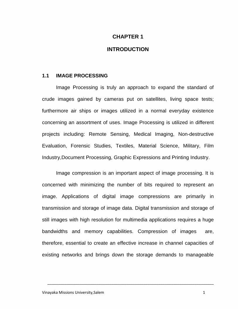
CHAPTER 1
INTRODUCTION
1.1 IMAGE PROCESSING
Image Processing is truly an approach to expand the standard of
crude images gained by cameras put on satellites, living space tests;
furthermore air ships or images utilized in a normal everyday existence
concerning an assortment of uses. Image Processing is utilized in different
projects including: Remote Sensing, Medical Imaging, Non-destructive
Evaluation, Forensic Studies, Textiles, Material Science, Military, Film
Industry,Document Processing, Graphic Expressions and Printing Industry.
Image compression is an important aspect of image processing. It is
concerned with minimizing the number of bits required to represent an
image. Applications of digital image compressions are primarily in
transmission and storage of image data. Digital transmission and storage of
still images with high resolution for multimedia applications requires a huge
bandwidths and memory capabilities. Compression of images are,
therefore, essential to create an effective increase in channel capacities of
existing networks and brings down the storage demands to manageable
______________________________________________________________________________
Vinayaka Missions University,Salem 2
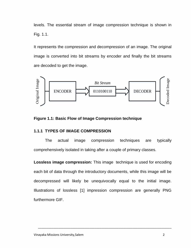
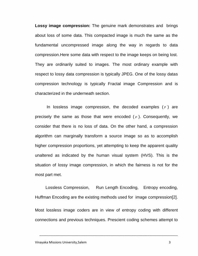
levels. The essential stream of image compression technique is shown in
Fig. 1.1.
It represents the compression and decompression of an image. The original
image is converted into bit streams by encoder and finally the bit streams
are decoded to get the image.
0110100110 DECODERENCODER
Bit Stream
Deco
ded
Im
ag
e
Ori
gin
al
Imag
e
Figure 1.1: Basic Flow of Image Compression technique
1.1.1 TYPES OF IMAGE COMPRESSION
The actual image compression techniques are typically
comprehensively isolated in taking after a couple of primary classes.
Lossless image compression: This image technique is used for encoding
each bit of data through the introductory documents, while this image will be
decompressed will likely be unequivocally equal to the initial image.
Illustrations of lossless [1] impression compression are generally PNG
furthermore GIF.
______________________________________________________________________________
Vinayaka Missions University,Salem 3
Lossy image compression: The genuine mark demonstrates and brings
about loss of some data. This compacted image is much the same as the
fundamental uncompressed image along the way in regards to data
compression.Here some data with respect to the image keeps on being lost.
They are ordinarily suited to images. The most ordinary example with
respect to lossy data compression is typically JPEG. One of the lossy datas
compression technology is typically Fractal image Compression and is
characterized in the underneath section.
In lossless image compression, the decoded examples ( 'P ) are
precisely the same as those that were encoded ( P ). Consequently, we
consider that there is no loss of data. On the other hand, a compression
algorithm can marginally transform a source image so as to accomplish
higher compression proportions, yet attempting to keep the apparent quality
unaltered as indicated by the human visual system (HVS). This is the
situation of lossy image compression, in which the fairness is not for the
most part met.
Lossless Compression, Run Length Encoding, Entropy encoding,
Huffman Encoding are the existing methods used for image compression[2].
Most lossless image coders are in view of entropy coding with different
connections and previous techniques. Prescient coding schemes attempt to
______________________________________________________________________________
Vinayaka Missions University,Salem 4
foresee every example from the specimens that have been already
encoded, which are accessible to both encoder and decoder. In image
compression, forecast is typically performed from adjacent pixels. When an
expectation has been figured, the remaining pixel is encoded as the slip
conferred by this forecast. Thus, the better expectation is, the lower will be
the entropy of the remaining pixels. The CALIC scheme [3] takes after this
technique, turning into a standout amongst the most productive lossless
image coders as far as compression execution. A disentanglement of CALIC
was embraced as the JPEG-LS standard. This disentangled adaptation of
CALIC is called LOCO-I [4], and its execution is near to CALIC with lower
multifaceted nature. Different lossless image encoders are PNG (proposed
as an eminence free distinct option for GIF) and JBIG (expected to bi-level
image coding and utilized as a part of fax transmission).
Medical imaging is a sample of utilization in which lossless
compression is needed, since all the image points of interest must be
protected so that medicinal investigation is not impeded. Another use of
lossless coding is image altering. In this sort of utilization, if lossy
compression is utilized, collective slips from progressive versions might
genuinely harm the last image quality. Perhaps, the lossless compression
yields poorer compression proportions when contrasted.Subsequently the
previous is not as often as possible utilized as the recent.
______________________________________________________________________________
Vinayaka Missions University,Salem 5
Different ways to deal with lossy coding have been taken in the
writing. The vector quantization [5], allows the modeling of probability
density function by distribution of prototype vectors. The better detailed
examples are put away in a codebook, which is shared by both encoder and
decoder. A comparative scheme is fractal coding [6], in which images use
themselves as their codebook. Unfortunately, both techniques are time
escalated, because of the quest for the codebook, and may deliver blocking
ancient rarities, i.e., the edges plunging two bordering pieces could be
distinguishable. A more fruitful way to deal with lossy compression has been
accomplished by transform techniques.
Image compression methods fall into two categories. The first
category is called predictive coding [4] and exploits redundancy in the image
data. Redundancy is a characteristic related to factors such as predictability,
randomness, and smoothness in the image. Techniques such as Delta
Modulation (DM) and Differential Pulse Code Modulation (DPCM) fall in this
category. In the second category, called transform coding, compression is
achieved by transforming the given image into another array such that a
large amount of information is packed into a small number of samples.
Techniques such as Karhunen-Loeve (K-L) decomposition, Discrete Cosine
Transform (DCT), and Discrete Wavelet Transform (DWT) fall in this
category.
______________________________________________________________________________
Vinayaka Missions University,Salem 6
1.1.2 ENTROPY CODING
A Morse code concept is utilized as a part of more cutting edge
techniques in case of entropy coding. In this connection, when we discuss
coding, we allude to allotting bits to speak to an image or a gathering of
images. All in all, if X is a discrete variable representing to any conceivable
image from an alphabet A , a symbol As , an image can be encoded
utilizing a coding capacity XC that maps s with a threshold and requested
sequence of binary symbols (bits). This sequence of bits is called code
word, and the table that maps every image into its code word is called
codebook. Obviously, genuine applications for the most part encode more
than an image from A , and consequently, when an sequence of L symbol
AssssssSLL ,,:,,
2121is encoded, the principle objective of data
compression is to accomplish the briefest length for the last bit stream, i.e.,
to minimize SC' , where s
LXXXC ,,,
21
' is the coding capacity for the
entire succession of symbol. A conceivable non- optimal solution for code
the sequence S is to pick a codebook that minimizes
L
XCXCXCSC 21
' for all conceivable coding assignments. Be
that as it may, better sequences can be accomplished in the event that we
don't concentrate on individual symbols yet in gatherings of them. Other
than minimized representation, the coding procedure must be reversible,
______________________________________________________________________________
Vinayaka Missions University,Salem 7
guaranteeing that an unraveling procedure can reproduce precisely the
starting symbol in the same request as they were encoded.
1.1.3 ARITHMETIC CODING
A more proficient entropy coding algorithm for low-entropy sources is
arithmetic coding. In this technique, the entire source succession
AssssssSLL ,,,:,,,
2121 is mapped into one and only code word, which
is related to the likelihood of the sequence L
SPSPSPSP 21
. The
thought in arithmetic coding is that, for every one of the sequences S of
length L , the more prominent SP , the shorter the code word. This code task
was produced by Pasco [8] and Rissanen [9] [10] in view of the early work of
Shannon [7]. A full clarification of arithmetic coding can be found in later
literature [11] [12].
1.2 WAVELET TRANSFORM
One of the sidelong impacts of block processing in the DCT is that
blocking ancient rarities show up in moderate to high compression
proportions. As per the HVS model, block edges are effortlessly recognized
and thus, the visual image quality is extremely degraded. In addition, excess
of image structural information is not optimally expelled from an image on
the grounds that every block is encoded freely, and just the DC part is
decorrelated by utilizing differential coding. The wavelet transform has the
______________________________________________________________________________
Vinayaka Missions University,Salem 8
capacity to defeat these downsides given that it might be connected to a
complete image, and thus it accomplishes better repetition evacuation
without blocking ancient rarity. Consequently, if the DWT is utilized for image
coding, better visual quality and compression execution is accomplished.
Thus, the JPEG 2000 standard [13] replaced the utilization of the DCT by
the DWT. Furthermore, lossless coding can be performed in JPEG 2000 by
applying a reversible integer to-integer wavelet transform [14] with precisely
the same compression algorithm as in the lossy case.
1.2.1 CONTINUOUS WAVELET TRANSFORM (CWT)
The Continuous Wavelet Transform (CWT) is the most recent solution
to overcome the shortcomings of the FT and STFT providing perfect
resolution in both the time domain and frequencydomain. The term wavelet
literally means small wave. A wavelet is a function of finite length (small) and
which is oscillatory (wave) having an average value, integral, of zero. These
are themost important properties of a wavelet as they satisfy the
admissibility and regularity conditions required for decomposition (analysis)
and reconstruction (synthesis) of a signal without loss of information. Further
information is provided in [15] regarding the details of the admissibility and
regularity conditions. Whereas basis functions for the FT, and hence the
STFT, are sinusoids (the FT composes a signal/function into a series of
sinusoids), the basis functions for the CWT are known as baby wavelets..
______________________________________________________________________________
Vinayaka Missions University,Salem 9
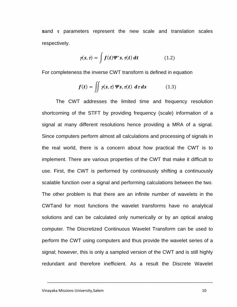
More specifically, the CWT decomposes a signal or function into a series of
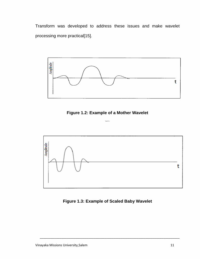
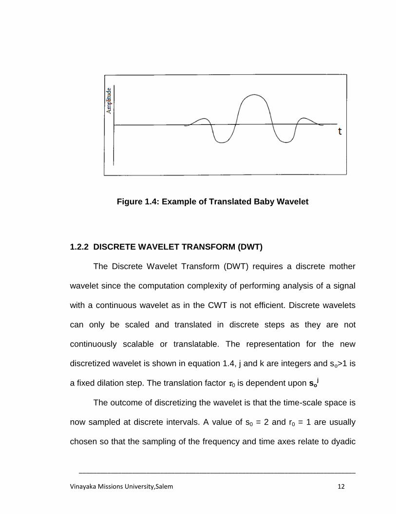
baby wavelet functions. These baby wavelets are derived from a single
prototype wavelet via dilations or contractions (scaling) and translations
(shifts). This prototype wavelet is aptly named the "mother wavelet". An
example of a mother wavelet and derived wavelets are shown in Fig. 1.2,
1.3, and 1.4.
A baby wavelet𝜳𝒔, 𝒕 is derived from the mother wavelet𝜳(𝒕) by
varying scaling andtranslation parameters s and respectively as shown in
equation1.1.The 1
𝑠 is for energy normalization across the different scales.
𝜳𝒔, 𝒕 =𝟏
𝒔𝜳
𝒕−
𝒔 (1.1)
The CWT is performed by multiplying the signal to be analyzed by all the
baby wavelets having the same scale (s) but different translations (). In
doing so, the scale information for every value in time is obtained. Scale
information is considered to be inversely related to the frequency information
as a larger scale value refers to lower frequency and vice-versa. The
process is then repeated using dilated or contracted baby wavelets at every
scale (s) until all scale-translation (, s) combinations of baby wavelets are
applied to the signal thus resulting in a time-scale MRA of the signal. Note
that the wavelet Multi Resolution Analysis (MRA) is in time-scale resolution
whereas the discussion earlier referred to a time-frequency resolution. The
______________________________________________________________________________
Vinayaka Missions University,Salem 10
sand parameters represent the new scale and translation scales
respectively.
𝒔, = 𝒇 𝒕 𝜳∗𝒔, 𝒕 𝒅𝒕 (1.2)
For completeness the inverse CWT transform is defined in equation
𝒇 𝒕 = 𝒔, 𝜳𝒔, 𝒕 𝒅 𝒅𝒔 (1.3)
The CWT addresses the limited time and frequency resolution
shortcoming of the STFT by providing frequency (scale) information of a
signal at many different resolutions hence providing a MRA of a signal.
Since computers perform almost all calculations and processing of signals in
the real world, there is a concern about how practical the CWT is to
implement. There are various properties of the CWT that make it difficult to
use. First, the CWT is performed by continuously shifting a continuously
scalable function over a signal and performing calculations between the two.
The other problem is that there are an infinite number of wavelets in the
CWTand for most functions the wavelet transforms have no analytical
solutions and can be calculated only numerically or by an optical analog
computer. The Discretized Continuous Wavelet Transform can be used to
perform the CWT using computers and thus provide the wavelet series of a
signal; however, this is only a sampled version of the CWT and is still highly
redundant and therefore inefficient. As a result the Discrete Wavelet
______________________________________________________________________________
Vinayaka Missions University,Salem 11
Transform was developed to address these issues and make wavelet
processing more practical[15].
Figure 1.2: Example of a Mother Wavelet
```
Figure 1.3: Example of Scaled Baby Wavelet
______________________________________________________________________________
Vinayaka Missions University,Salem 12
Figure 1.4: Example of Translated Baby Wavelet
1.2.2 DISCRETE WAVELET TRANSFORM (DWT)
The Discrete Wavelet Transform (DWT) requires a discrete mother
wavelet since the computation complexity of performing analysis of a signal
with a continuous wavelet as in the CWT is not efficient. Discrete wavelets
can only be scaled and translated in discrete steps as they are not
continuously scalable or translatable. The representation for the new
discretized wavelet is shown in equation 1.4, j and k are integers and so>1 is
a fixed dilation step. The translation factor 0 is dependent upon soj
The outcome of discretizing the wavelet is that the time-scale space is
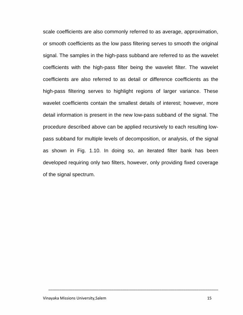
now sampled at discrete intervals. A value of s0 = 2 and r0 = 1 are usually
chosen so that the sampling of the frequency and time axes relate to dyadic
______________________________________________________________________________
Vinayaka Missions University,Salem 13
sampling which is illustrated in Fig 1.5. One reason forthe choice of dyadic
sampling is that it is a very natural choice for computers [15].
Ψj,k(t) = 1
𝑆0𝑗Ψ
1−𝑘𝑜𝑆0𝑗
𝑆0𝑗 (1.4)
Even with a discrete wavelet the wavelet transform requires an infinite
number of searing‟s and translations of the mother wavelet, however, this is
not possible with a discrete algorithm such as the DWT.
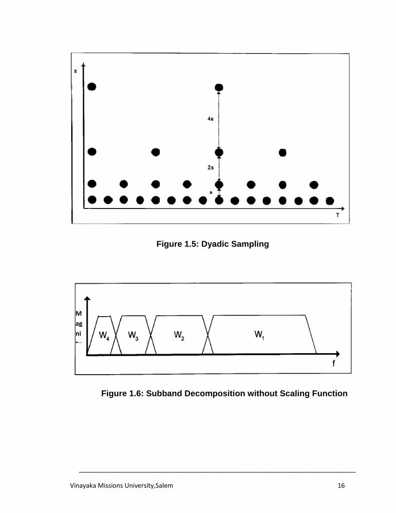
In order to provide good coverage of the signal spectrum using a finite
number of wavelets the scaling factor of 2 is used and by doing so each
wavelet will touch each other as shown in Fig.1.5.
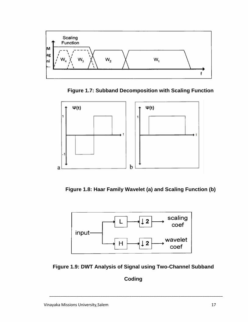
It is impossible to cover the spectrum all the way down to zero as the
spectrum is continually halved and never reaches zero. In such case, a
scaling function helpswhich effectively corks the remaining spectrum, thus
requiring only a finite number of wavelets. As shown in Fig. 1.7, this cork fills
the void with a low-pass spectrum commonly referred to as the scaling filter
[15]. Similarly the translation factor is chosen to be 2 to provide complete

______________________________________________________________________________
Vinayaka Missions University,Salem 14
coverage of the time range of the signal. Examples of a Haar family wavelet
and scaling functions are shown in Fig. 1.8 a and b respectively.
The Quadrature Mirror Filter (QMF) bank performsan analysis of
speech signals and named their analysis scheme as subband coding. A
technique very similar to pyramidal coding[16] and is also known as MRA
mentioned earlier. The wavelet transform is computed by changing the scale
of an analysis window (mother wavelet) and shifting this window in time
across the signal to obtain the time-scale(10)representation of the signal.
Similarly in subband coding a time-scale representation of a digital signal is
obtained using digital filtering techniques. The signal is passed through a
series of high-pass filters and low-pass filters with different cut-off
frequencies to analyze the high frequency and low-frequency components of
a signal respectively at different scales. Their solution of the signal is
changed by the filtering operations and the scale is changed by up-sampling
and down-sampling operations. The techniques used in subband coding can
be applied to the DWT. Two digital filter banks are used to perform low-pass
and high-pass filtering on the original signal, effectively splitting it into two
frequency spectrums, or subband. Each subband is down-sampled by a
factor of two to keep the total number of samples the same as the original
signal. The samples in the low-pass subband are referred to as the
scale(scaling) coefficients with the low-pass filter being the scaling filter. The
______________________________________________________________________________
Vinayaka Missions University,Salem 15
scale coefficients are also commonly referred to as average, approximation,
or smooth coefficients as the low pass filtering serves to smooth the original
signal. The samples in the high-pass subband are referred to as the wavelet
coefficients with the high-pass filter being the wavelet filter. The wavelet
coefficients are also referred to as detail or difference coefficients as the
high-pass filtering serves to highlight regions of larger variance. These
wavelet coefficients contain the smallest details of interest; however, more
detail information is present in the new low-pass subband of the signal. The
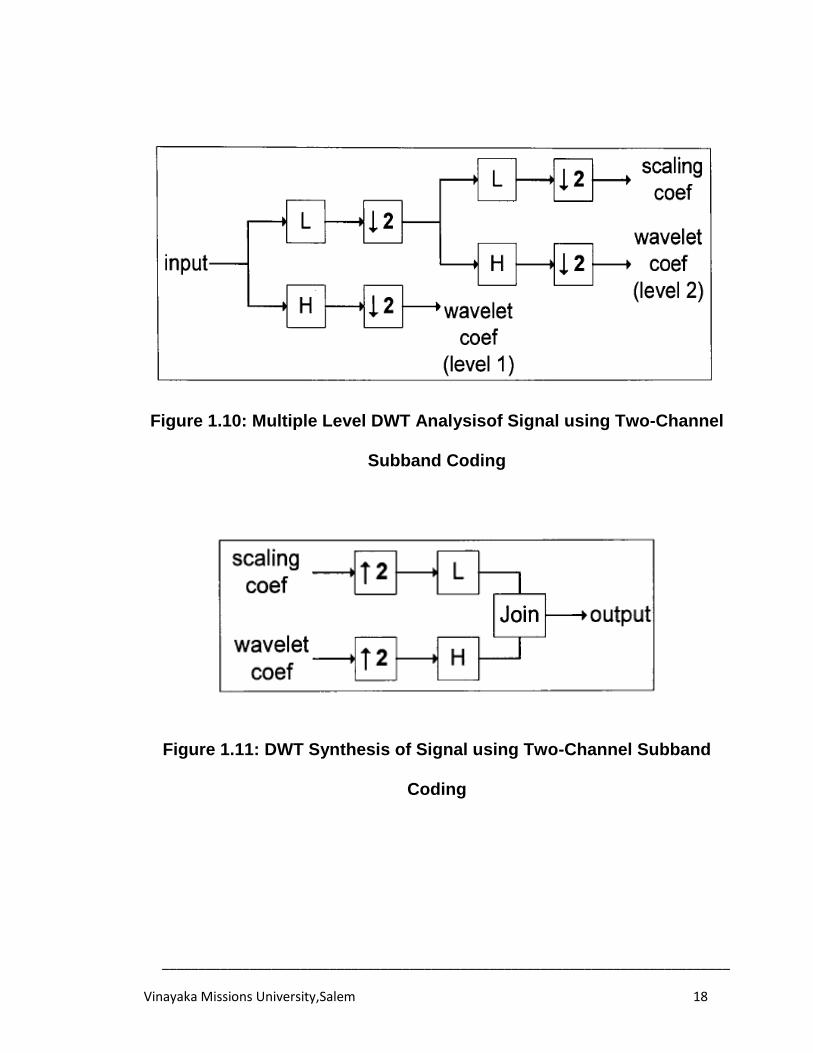
procedure described above can be applied recursively to each resulting low-
pass subband for multiple levels of decomposition, or analysis, of the signal
as shown in Fig. 1.10. In doing so, an iterated filter bank has been
developed requiring only two filters, however, only providing fixed coverage
of the signal spectrum.
______________________________________________________________________________
Vinayaka Missions University,Salem 16
Figure 1.5: Dyadic Sampling
Figure 1.6: Subband Decomposition without Scaling Function
M
ag
ni
tu
d
e
______________________________________________________________________________
Vinayaka Missions University,Salem 17
Figure 1.7: Subband Decomposition with Scaling Function
Figure 1.8: Haar Family Wavelet (a) and Scaling Function (b)
Figure 1.9: DWT Analysis of Signal using Two-Channel Subband
Coding
M
ag
ni
tu
d
e
Ψ(t) Ψ(t)
1
-1
1
______________________________________________________________________________
Vinayaka Missions University,Salem 18
Figure 1.10: Multiple Level DWT Analysisof Signal using Two-Channel
Subband Coding
Figure 1.11: DWT Synthesis of Signal using Two-Channel Subband
Coding
______________________________________________________________________________
Vinayaka Missions University,Salem 19
Reconstruction of the signal, or synthesis, is performed in the opposite
manner by using synthesis filters and upsampling as demonstrated in Fig.
1.11.
1.3 BIORTHOGONAL WAVELETS
A transform is described as being orthonormal if both its forward and inverse
transforms are identical; therefore an orthonormal wavelet is one that is
used in both analysis and synthesis of signal. A filter having linear phase is
one whose impulse response is either symmetric or anti-symmetric. Linear
phase is important for a variety of reasons in applications where the signal is
of finite duration, such as image compression. As mentioned earlier, two-
channel subband transforms are used to perform the DWT on a signal.
Unfortunately, there are no two-channel linear-phase subband filters with
finite support that are also orthonormal. The solution is to use two symmetric
wavelets for analysis and synthesis that are orthogonal to each other, or
biorthogonal. These biorthogonal wavelets exhibit linear phase and therefore
are now useful [17].A compression rate of 1:300 is achievable using
wavelets [18 ]. A family of biorthogonal wavelets that has proved useful in
applications such as image compression is the Cohen-Daubechies-
Feauveau (CDF) wavelet family. The CDF 5/3 and CDF 9/7 are two specific
wavelets that will be used as continuing examples throughout this thesis as
they provide an interesting comparison.
______________________________________________________________________________
Vinayaka Missions University,Salem 20
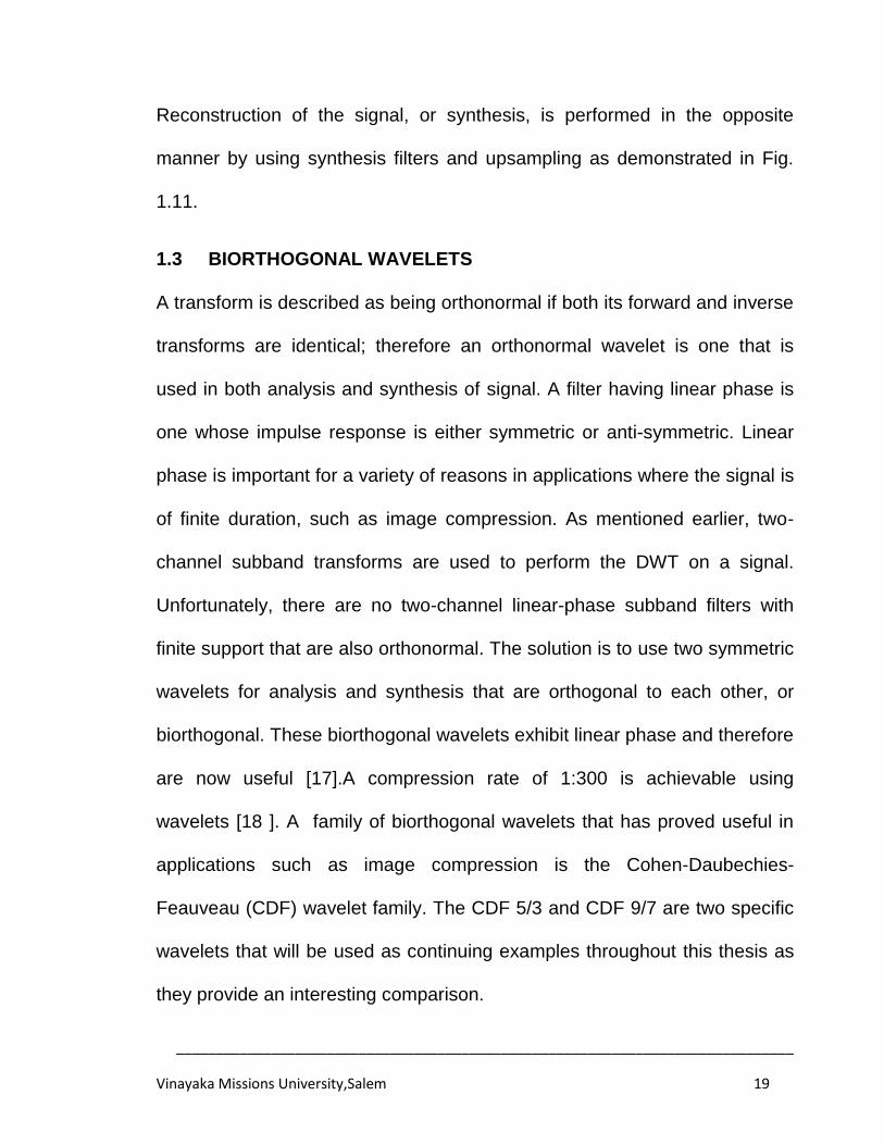
1.3.1 CDF 5/3
The Cohen-Daubechies-Feauveau (CDF) 5/3 biorthogonal wavelet is
a simple wavelet that has two sets of scaling and wavelet functions for
analysis and synthesis, hence biorthogonality. The CDF 5/3 wavelet has a 5-
tap low-pass analysis filter h (z) and 3-tap high-pass analysis filter g (z),
hence 5/3. The CDF 5/3 also has a 3-tap low-pass synthesis filter h (z) and
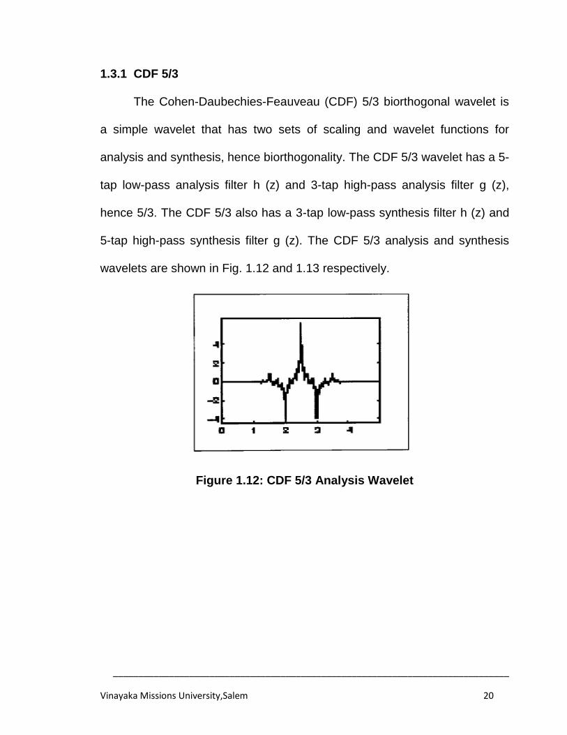
5-tap high-pass synthesis filter g (z). The CDF 5/3 analysis and synthesis
wavelets are shown in Fig. 1.12 and 1.13 respectively.
Figure 1.12: CDF 5/3 Analysis Wavelet
______________________________________________________________________________
Vinayaka Missions University,Salem 21
Figure 1.13: CDF 5/3 Synthesis Wavelet
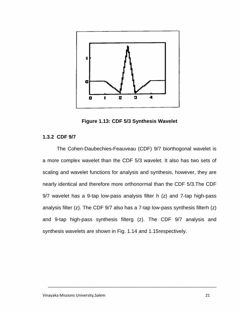
1.3.2 CDF 9/7
The Cohen-Daubechies-Feauveau (CDF) 9/7 biorthogonal wavelet is
a more complex wavelet than the CDF 5/3 wavelet. It also has two sets of
scaling and wavelet functions for analysis and synthesis, however, they are
nearly identical and therefore more orthonormal than the CDF 5/3.The CDF
9/7 wavelet has a 9-tap low-pass analysis filter h (z) and 7-tap high-pass
analysis filter (z). The CDF 9/7 also has a 7-tap low-pass synthesis filterh (z)
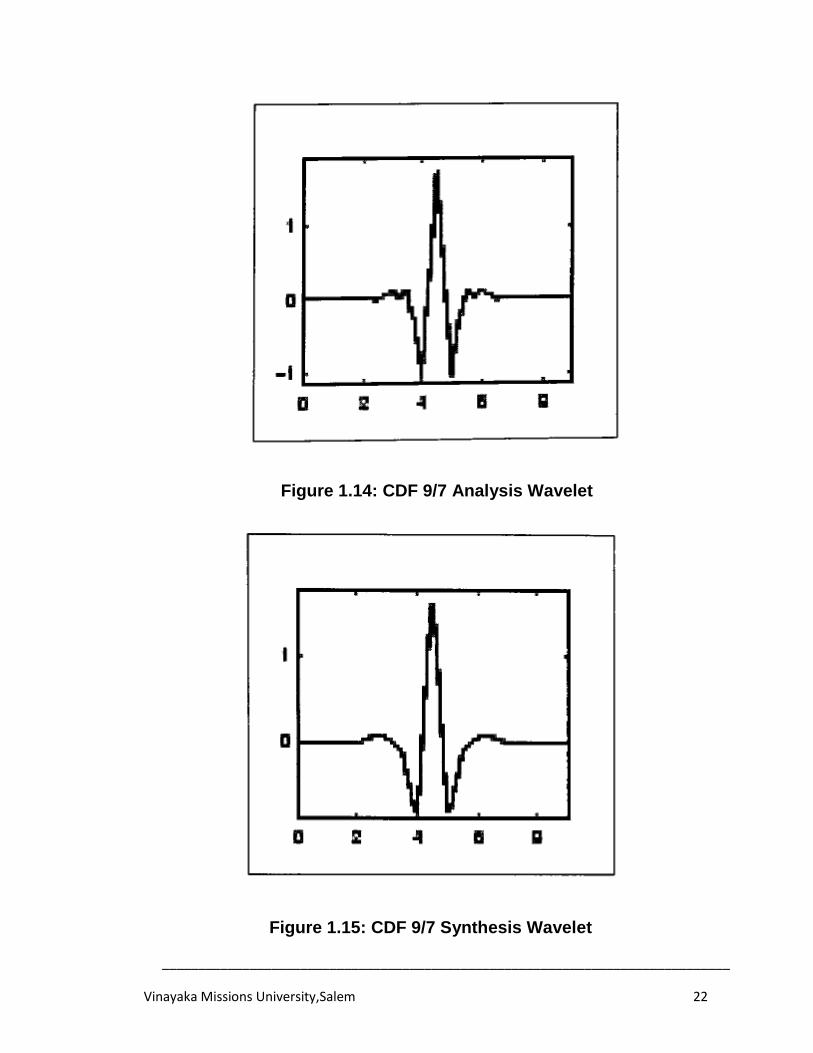
and 9-tap high-pass synthesis filterg (z). The CDF 9/7 analysis and
synthesis wavelets are shown in Fig. 1.14 and 1.15respectively.
______________________________________________________________________________
Vinayaka Missions University,Salem 22
Figure 1.14: CDF 9/7 Analysis Wavelet
Figure 1.15: CDF 9/7 Synthesis Wavelet
______________________________________________________________________________
Vinayaka Missions University,Salem 23
1.4 JPEG2000 STANDARD FOR STILL IMAGE COMPRESSION
In early 1990s, a number of new image compression algorithms such as
CREW (compression with reversible embedded wavelets) and EZT
(embedded zero tree)were developed to provide not only superior
compression performance, but also a new set of features which were not
seen earlier. Based on industrial demand, JPEG2000 project was
proposed by JPEG (Joint Photographic Expert Group) committee in
1996. At the first evaluation, 24 algorithms were submitted and
evaluated. Based on this assessment, it was decided to create a
JPEG2000 “Verification Model” (VM) which lead to a reference
implementation for the following standard process. The first verification
model VM0 is based on Wavelet Coded Quantization (WCQT) algorithm
[19]. In 1998, EBCOT (Embedded Block Coding with Optimal Truncation)
algorithm was adopted into VM3. The document describing the basic
JPEG2000 decoder (part I) became Committee Draft (CD) in 1999.The
JPEG2000 finally became an international standard in December 2000.
The JPEG2000 standard provides a set of features that are of
vital importance to performance and provides capabilities to markets that
currently do not use compression. The markets and applications better
served by the JPEG2000 standard are internet, colour facsimile,
scanning, digital photography, remote sensing, mobile and medical
______________________________________________________________________________
Vinayaka Missions University,Salem 24
imagery. Each application area imposes some requirements that the
standard should fulfill. The main features that this standard possesses
are: superior low bit rate performance, continuous-tone and bi-level
compression, lossless and lossy compression, progressive transmission
by pixel accuracy and resolution, random code stream access and
processing, many high-end etc., by taking advantage of new
technologies. It addresses areas where current standards fail to produce
the best quality or robustness to bit-errors.
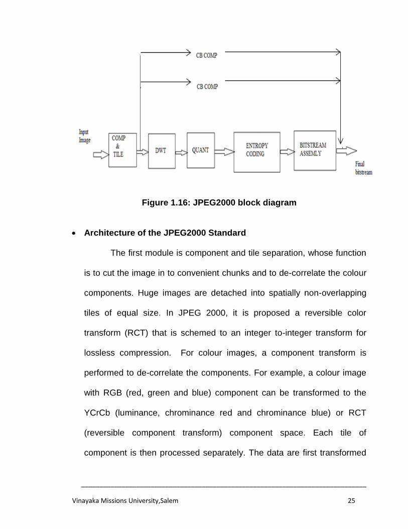
The block diagram of JPEG2000 encoder is shown in fig.1.16.
Before proceeding with the details of each block, it should be mentioned
that the standard works on image tiles or blocks. The term tiling refers to
the partition of the original (source) image into rectangular blocks (tiles),
which are compressed independently, as though they were entirely
distinct images. This is the strongest form of spatial partitioning, in that all
operations, including component mixing, wavelet transform, quantization
and entropy coding are performed independently on the different blocks
of the image. All blocks have exactly the same dimensions. Arbitrary
block sizes are allowed. Tiling reduces memory requirements and
constitutes one of the methods for the efficient extraction of a region of
the image.
______________________________________________________________________________
Vinayaka Missions University,Salem 25
Figure 1.16: JPEG2000 block diagram
Architecture of the JPEG2000 Standard
The first module is component and tile separation, whose function
is to cut the image in to convenient chunks and to de-correlate the colour
components. Huge images are detached into spatially non-overlapping
tiles of equal size. In JPEG 2000, it is proposed a reversible color
transform (RCT) that is schemed to an integer to-integer transform for
lossless compression. For colour images, a component transform is
performed to de-correlate the components. For example, a colour image
with RGB (red, green and blue) component can be transformed to the
YCrCb (luminance, chrominance red and chrominance blue) or RCT
(reversible component transform) component space. Each tile of
component is then processed separately. The data are first transformed
______________________________________________________________________________
Vinayaka Missions University,Salem 26
into the wavelet domain, and then quantized. Later, the quantized
coefficients are rearranged to facilitate localized spatial and resolution
access. Each subband of quantized coefficients is separated into non-
overlapping rectangular blocks. Three spatially co-locate rectangles (one
from each subband at a given resolution level) form a packet partition.
Each packet partition is further divided into code blocks, each of which is
compressed into an embedded bit stream with a recorded rate-distortion
curve. The embedded bitstreams of code blocks are collected into
packets, each of which represents a quality increment of one resolution
at one spatial location. Collection of packets from all packet partitions of
all resolution levels of all tiles and all components, we form a layer that is
one quality increment of entire image at full resolution. The JPEG2000
bitstream may consist of numerous layers.
The Wavelet Transform
Blocks are processed to get different decomposition levels using
wavelet transform. These disintegration levels contain a number of
subbands populated with coefficients that describe the horizontal and
vertical spatial frequency characteristics of the novel block. The
coefficients provide local frequency information. To perform DWT, the
standard uses a 1D subband decomposition of a 1D set of samples into
______________________________________________________________________________
Vinayaka Missions University,Salem 27
low-pass samples, signifying a downsampled low-resolution version of
the original set, and high-pass samples, representing a down-sampled
residual form of the original set, needed for the perfect reconstruction of
the original set from the low-pass set. In general, any user supplied
wavelet filter bank may be used. The DWT can be irreversible or
reversible. The default irreversible transform is realized by means of the
Daubechies 9-tap/7-tap filter bank [20]. The default reversible
transformation is implemented by means of the 5-tap/3-tap filter bank.
The standard supports two filtering modes: convolution-based and lifting-
based. Convolution-based filtering consists in performing a series of dot
products between two filter masks and the signal. Lifting-based filtering
consists of a sequence of very simple filtering operations for which
alternate odd sample values of the signal are updated with a weighted
sum of even sample values, and even sample values are restructured
with a weighted sum of odd sample values.
Quantization
Quantization is the process by which the transform coefficients
are reduced in precision. This operation is lossy, unless the quantization
step is one and the coefficients are integers, as produced by the
reversible integer 5/3 wavelet. One quantization step per subband is
allowed. All quantized transform coefficients are signed values even
______________________________________________________________________________
Vinayaka Missions University,Salem 28
when the original components are unsigned. These coefficients are
expressed in a sign-magnitude representation prior to coding.
Entropy Coding
Each subband of the wavelet decomposition is divided into
rectangular blocks, called code-blocks, which are coded independently
using arithmetic coding. This method is known as embedded block
coding with optimized truncation (EBCOT). Such a partitioning reduces
memory requirements in both hardware and software implementations
and provides a certain degree of spatial random access to the bitstream.
Bitstream Assembly
The bit streams of the code-blocks are assembled by the bitstream
assembler module to form the compressed bitstream of the image. This
block determines how much bit-stream of each code-block is put to the final
bit stream. The final bit stream consists of the image data with all the
signaling required to decompress it. It is composed of the header and tile
data that specify coding parameters in a hierarchical manner and the
encoded data for each tile.
______________________________________________________________________________
Vinayaka Missions University,Salem 29
1.5 NEED FOR THE STUDY
The goal of a good video compression algorithm is to represent a
video sequence with minimal bit-rate, while preserving an appropriate level
of picture quality for the given application. Compression is achieved by
identifying and removing redundancies. Most video compression
applications demand high quality video encoding and transmission.
However, high quality raw video requires enormous amount of storage
space and communication bandwidth. Video security systems require
sufficient image detail to make positive identifications.
The single most important element in delivering extremely high quality
video lies in the selection of a superior Encoding /Decoding (CODEC)
Algorithm. The wavelet offers a scalable video solution with features for the
control of resolution, frame rate, bit depth, subjective quality, bandwidth and
option to deliver lossy or lossless compression. These criteria have been
adopted in the proposed work.
1.6 OBJECTIVES
The main objective is to develop new algorithms and design
architecture for discrete wavelet transform based video encoder. Special
emphasis has been laid in achieving high compression, improved coding
efficiency; high quality of reconstructed image compared to DCT based
MPEG standards. The objectives are as follows:
______________________________________________________________________________
Vinayaka Missions University,Salem 30
1. To design an efficient VLSI Architecture for Lifting Based 5/3 DWT
that uses less hardware in terms of dedicated multipliers compared
to existing architectures. The proposed architecture was targeted
on VIRTEX-IV FPGA. Architecture has been realized using
hardware description language, VHDL.
2. To develop DWT and SPIHT Algorithms and their inverse for
image compression in MATLAB in order to ascertain the
methodology adopted in the design. MATLAB results will also
serve to validate the hardware results.
3. Simulate and Synthesize the above hardware implementation by
Design Suite 14.5 software of Xilinx.
4. In this work the, the DWT Convolution method utilising 9/7 channel
with arithmetic coding, which gives great compression quality, yet
is especially difficult to actualize with high effectiveness because of
the unreasonable way of the channel coefficients have been
proposed.
______________________________________________________________________________
Vinayaka Missions University,Salem 31
1.7 ORGANIZATION OF THE THESIS
In this work, we schemed to generate techniques for the image
compression utilizing DWT technique. In Chapter 1 a brief introduction to
the concept of image compression is given followed by basics in wavelet
transform and JPEG2000 standard for still image compression. In Chapter2
review of literature and related work is discussed. In Chapter 3 a 2D DWT
based image compression technique is introduced, which is suitable for the
constant application. Chapter 4 gives an image compression technique in
light of SPIHT algorithm with DWTimplemented. In Chapter 5 a novel
technique for the compression of video data utilizing DWT for on-going
usage is exhibited, which is checked utilizing FPGA. In the consequent part
the general conclusion for this proposal and future bearing is given.
______________________________________________________________________________
Vinayaka Missions University,Salem 32
CHAPTER 2
LITERATURE REVIEW
2.1 GENERAL
The discrete wavelet transform (DWT) stands out amongst the most
utilized methods for signal analysis and image handling applications. The
DWT performs a multi-resolution signal investigation which has move ability
in both time and frequency domains. Hence it is a standout amongst the
most critical uses for DWT for image compression as in the JPEG 2000. The
accessible DWT architecture can be isolated comprehensively into two
schemes named as convolution scheme and lifting scheme. Typically
convolution scheme is utilized to implement DWT filters. Be that as it may,
this scheme utilizes large number of multipliers which is extremely hard to
execute and takes a lot of hardware resources. To dispense with those
issues, lifting scheme is used. This scheme utilizes the essential convolution
comparisons wherein the number of multipliers are definitely decreased.
Because of this reason lifting schemes is generally used to design an
integrated chip than the convolution scheme. A percentage of the initial
papers on wavelet image compression [21] present an astounding
performance, and bolster the utilization of the wavelet transform in image
______________________________________________________________________________
Vinayaka Missions University,Salem 33
compression. Wavelets are being utilized as a part of mixed bag of
utilizations like Image compression, edge detection, interpolation of finite
signals [22-26]. So far the system of Estimate Wavelet Transform is utilized
as a part of approximating the single dimensional signals [27-30]. This is the
first run through when it is connected to approximate the broken two
dimensional images. The target is to rough the misfortune happened in the
time. Three methods are applied, namely, (1) Coiflet wavelet utilizing EWT,
(2) Daubechies wavelet utilizing EWT, and (3) Gaussian Low pass filter. The
third one is a conventional strategy for oversampling the image by taking
appropriate size of Gaussian window and the initial two are the novel
systems to handle the issue. On utilizing initial two procedures, the span of
the original image gets multiplied and the resultant image gets to be smooth.
Eventually these double size images would create noise, with the goal that
they can be separated utilizing image compression procedure of discrete
wavelet transform. The extent of the compressed image will be the same as
the first image and that too without irregularity in the image. Numerous lifting
based architecture design have been proposed for productive equipment
usage of both 1D and 2D-DWT architectures. The extensive literature
collected related to the performance improvement of video compression
system using scalable, block based and motion edge based techniques is
critically reviewed and presented in this chapter. Also, comprehensive
______________________________________________________________________________
Vinayaka Missions University,Salem 34
review of literature on evolution of various Codec to achieve good
compression and quality for video compression systems is presented.
2.2 REVIEW LITERATURE
Mallat [31] has Proposed adjusted calculation for lifting processing
where the basic way postpone for the lifting mathematical statements is 5Tm
+ 8Ta, where Tm and Ta mean the multiplier and snake defer individually.
The essential purpose for this expansive postponement is stacking of
multipliers from the inputs to yields. This limits the processing speed of the
system. To restrain the impact, the system of flipping has been presented in
which scales the deferral is down to 3Tm + 4Ta. As a productive result, the
preparing rate increments altogether when the flipped comparisons are
mapped into equipment.
Durgasowjanya et al. [32] proposed altered point 1-D DWT utilizing
Lifting Scheme, which work utilizes just 3% of aggregate cut register of
Virtex-II FPGA.
Nagabushanam M and S. Ramachandran [33] proposed lifting based
1D/2D/3D DWT-IDWT structural planning, which utilizes just 5% of
aggregate cut register of Virtex-IV FPGA.
______________________________________________________________________________
Vinayaka Missions University,Salem 35
K. Andra et al. [34] sums up the lifting based structural planning,
which comprises of two line processors, two segment processors and two
memory modules. In any case, the memory control rationale of the structural
engineering is mind boggling.
Chang et al. [35] proposed a few advancement procedures that give
the designer more control over the range to blunder ex-transform off amid
information way accuracy enhancement that would not be accessible with
straightforward truncation. A mistake model is created for viper and
multiplier circuits. On the other hand, one of the issues confronted is the
vulnerability in genuine mistake of the framework which relies upon the real
estimation of the information. The upper bound on mistake skews toward
bigger positive values as we diminish the bit distributed per pixel. In this
work, we make utilization of a progressively reconfigurable structural
planning to alter the asset distribution for the framework in light of the image
quality needed by the application. The method reduced the memory access
for minimizing the overall power consumption at the cost of a few local
registers.
Benkrid et al. [36] examine that the general execution and region
depends essentially on the exactness of middle of the road bits utilized as a
part of the outline. This persuades us to further take a gander at bit
distribution as another part of polymorphism in our Poly-DWT structure.
______________________________________________________________________________
Vinayaka Missions University,Salem 36
K.Yamuna et al. [37] has demonstrated DWT architecture based on
lifting scheme algorithm. The design is interfaced with SIPO and PISO to
reduce the number of I/O lines on the FPGA. The design is implemented on
Spartan III device and is compared with lifting scheme logic. The design
operates at frequency of 520 MHz and consumes power less than 0.1 W.
The design is suitable for real time data processing and is modeled using
HDL and is implemented on FPGA.
P. Rajesh et al. [38] has proposed an efficient VLSI based
architecture for implementing Discrete Wavelet Transform (DWT) of 5/3
filter. The architecture includes transforms modules, a RAM and bus
interfaces. This construction works in non separable fashion using a serial-
parallel filter with distributed control to calculate all the DWT (1D-DWT and
2D-DWT) resolution levels. The block has a high computation task and
architecture gives the computation time of 2.36 ms at the operating
frequency of 100 MHz.
Rekha et al. [39] has proposed precision-aware approaches and
associated hardware implementations for performing the DWT. It presents
Bit Parallel (BP) architecture and Digital Serial (DS) design methodologies.
These methods enable use of an optimal amount of hardware resources in
the DWT computation. Experimental measurements of design performance
in terms of area, speed, and power for 90-nm complementary metal–oxide
______________________________________________________________________________
Vinayaka Missions University,Salem 37
semiconductor implementation are presented. The codes were written in
Verilog. The same has been simulated using the Modelsim 6.2. The results
in terms of numbers and waveforms are analyzed to get accurate results.
H. Chen et al. [40] demonstrated folded architecture and is simple in
terms of hardware complexity.
C. C. Liu et al. [41] showed novel technique and control complexity of
the architecture is very simple. All other architectures have comparable
hardware complexity and primarily differ in the number of registers and
multiplexer circuitry.
H. Liao et al. [42] designed an architecture in which the number of
switches, multiplexers and control signals used in the architectures are quite
large.
Jerome Shapiro [43] proposed a new technique for image coding that
produces a fully embedded bit stream. Furthermore, the compression
performance of the algorithm is competitive with virtually all known
techniques. The remarkable performance is attributed to the use of the
following four features. DWT de-correlates most sources fairly well, and
allows the more significant bits of precision of most coefficients to be
efficiently encoded as part of exponentially growing zerotree. Zerotree
coding, which by predicting insignificance across scales using an image
model that is easy for most images to satisfy, provides substantial coding
______________________________________________________________________________
Vinayaka Missions University,Salem 38
gain over the first order entropy for significant maps. Successive
approximation, which allows the coding of multiple significance map
zerotrees, and allows the encoding or decoding to stop at any point.
Adaptive arithmetic coding allows the entropy coder to incorporate learning
into the bit stream itself. The precise rate control achieved with this algorithm
is a distinct advantage. The user chooses a bitrate and encodes the image
to exactly the desired bitrate. Furthermore, since no training is required, the
algorithm is fairly general and performs remarkably well with most type of
images.
Kim and Pearlman [44] introduced 3D SPIHT video coding scheme
which is based on the subset partitioning algorithm in 3D hierarchical tree. It
is simple and performs well for still images, even without motion
compensation in its extension from 2D SPIHT to 3D. Although there is no
motion estimation or compensation in this method, it performs measurably
and visually better. Finally, the fact that the bit stream is the output of the
fully embedded wavelet coder, it is capable of delivering progressive buildup
of fidelity and scalability in frame size and rate.
Karlekar and Desai [45] analyzed the performance of DWT based
video coding scheme. It delivers a better way to address scalability
functionalities, than MPEG-2. To code wavelet coefficients resourcefully, set
partitioning in hierarchical trees (SPIHT) and adaptive arithmetic coding
______________________________________________________________________________
Vinayaka Missions University,Salem 39
algorithms were introduced. Motion compensation (MC) is done in spatial
domain to remove temporal redundancy present between frames. To avoid
blocking artifacts caused by block motion compensation, overlapping block
motion compensation (OBMC) is done. The video encoder was improved
upon by incorporating B (bidirectional prediction) frames and with better rate
control scheme.
Beong-Jo Kim et al. [46] highlighted low bit rate, scalable video coding
with 3D SPIHT algorithm. 3D spatio-temporal orientation trees coupled with
powerful SPIHT sorting and refinement reduces 3D SPIHT vocoder is so
efficient that it provides analogous performance. In addition to rate scalable,
this systemallows multi resolution scalability in encoding and decoding in
both time and space from one bit-stream. This added functionality along with
many desirable attributes, such as fully embedded-ness for progressive
transmission, precise rate control for constant bit-rate traffic, and low-
complexity for possible software-only video applications, made this video
coder an attractive candidate for multimedia applications.
Danyali and Mertins [75] proposed a modified 3D SPIHT algorithm
called 3D virtual SPIHT for very low bit-rate wavelet based video coding. In
this work, it decomposes the coarsest level of the wavelet coefficients to
reduce the number of three-dimensional (spatio-temporal) sets in the 3D
SPIHT algorithm. The simulation results show that the proposed Codec has
______________________________________________________________________________
Vinayaka Missions University,Salem 40
better performance than the original 3D SPIHT algorithm, especially for very
low bit-rate video coding. Also using arithmetic coding output bit stream,
PSNR is improved. The low complexity of the Codec and the embeddedness
property of the output bitstream make it a convenient coding technique for
Internet video streaming applications. Moreover, it has good potential to
carry spatial and temporal scalability, which are especially important for the
new multimedia applications.
Ekram Khan and Mohammed Ghanbari [48] proposed an efficient
extension of virtual set partitioning in hierarchical trees (VSPIHT) for color
image coding. This new scheme, Color-Virtual-SPIHT (CVSPIHT) generates
fully embedded bit stream similar to SPIHT. It combines the zerotrees of
three color planes in two steps. First, zerotrees within the same color planes
are joined together by VSPIHT, then resulting longer zerotrees of three
planes are combined through a novel composite tree. The simulation results
show the improved performance of the proposed method compared to
SPIHT based color coding scheme. The advantage of CVSPIHT is the lower
initialization cost as compared to CSPIHT. Since dependency between the
luminance and chrominance motion is greater, it is expected to achieve even
larger improvement for video.
Xun Guo et al. [49] realized ed a Wyner-ziv video coding scheme
based on SPIHT which utilizes not only the spatial and temporal
______________________________________________________________________________
Vinayaka Missions University,Salem 41
correlations, but also the higher-order statistical correlations. Wyner-Ziv
theory on source coding with side information is employed as the basic
coding principle, which makes the independent encoding and joint decoding
become possible. In this scheme, wavelet transform is first used to de-
correlate the spatial dependencyof a Wyner-Ziv surround. Then, the
quantized transform coefficients are organized by using magnitude with a
set partitioning sorting algorithm. The ordered planes are coded using
Wyner-Ziv coding based on turbo codes. At the decoder side, the
information generated by motion compensated interpolation is used to
conditionally decode the Wyner-Ziv frame. Overall, without increasing
encoder complexity too much, the proposed scheme achieves promising
performance compared to the results without or with little entropy coding.
Anhong Wang et al. [50] proposed a novel scheme for scalable
distributed video coding (SDVC), which deals with quality scalabilities. More
specifically, efficient H.264/AVC intra-frame coding is used to obtain a base
quality layer, the residual between the base layer and the original video is
encoded by distributed video coding (DVC) with SW-SPIHT (Slepian-Wolf)
to generate the enhancement layer. The side information is generated by the
residual between the base layer and the frame interpolated by motion
estimation. Since the residual coding exploits the similarity between the
base layer and enhancement layer, experimental results show this SDVC
______________________________________________________________________________
Vinayaka Missions University,Salem 42
approach is more efficient than the referenced, but with similar encoding
computation.
Liang Zhang et al. [51] introduced a novel data structure for
magnitude - ordering 3D wavelet transform coefficients. The proposed 3D
data structure, which consists of temporal 1D orientation trees followed by
spatial 2D orientation trees, exploits self-similarity not only across spatial
sub bands, but also across temporal sub bands. With the decoupled feature
of the proposed data structure, embedded color bitstream algorithm
achieves a better bit allocation among the three components of color video
sequences. In terms of PSNRs, the proposed embedded color bitstream
algorithm outperforms the coding algorithm based on asymmetric 3D
orientation trees. One advantage of video compression with wavelet-based
approaches is, its scalability with regard to different temporal, spatial, and
quality-level resolutions. Although this work focused only on the issue of
efficiency in 3D wavelet coefficient coding, the proposed decoupled 3D zero
tree data structure can be applied to build a new scalable wavelet video
coder.
Li Wern Chew et al. [52] proposed a new reduced Memory SPIHT
Coding with Wavelet Transform.Traditional wavelet-based image coding
applies the discrete wavelet transform (DWT) on an image using filter banks
over rings of characteristic zero. If the level of the DWT decomposition
______________________________________________________________________________
Vinayaka Missions University,Salem 43
increases, the number of bits needed to represent the wavelet coefficients
also increases. A significant amount of memory is required to store these
wavelet coefficients especially when the level of DWT decomposition is high.
Here, a post-processing method is proposed to fix the amplitude of the
wavelet coefficients to pre-defined N-bits. The SPIHT coding is then
performed to encode these coefficients to realize compression. The main
advantage of this proposed work is the significant reduction in memory
requirements for wavelet coefficients storage during bit-plane coding.
Simulation results show that the proposed SPIHT coding using wavelet
transform with post-processing gives an equally good compression
performance when M-3 N M-1 where M and N are the number of bits
needed to represent the largest wavelet coefficient without and with post
processing respectively.
Shang-Hsiu Tseng and Aldo Morales [53] proposed a 3D SPIHT with
low-memory usage (3D SPIHT-LM) concept. In this method, unnecessary
lists are discarded and the process length of the sorting phase is shortened
to reduce coding time and memory usage. Memory usage is a weakness
when transmitting video in a limited bandwidth or hardware environment
such as cellular phones or portable devices. Traditional methods for video
encoding and compression take time to compute, which can affect video
transmission quality. Additionally, video transmission data necessitate large
______________________________________________________________________________
Vinayaka Missions University,Salem 44
memory space. In this work, the authors successfully extended and
implemented a 3D SPIHT-LM algorithm on MATLAB and, provided
experimental results show that the proposed method reduces memory
usage, run time and improves PSNR over the original 3D SPIHT.
Andreas Burg et al. [54] introduced the first VLSI implementation of a
real-time color video compression/decompression system, based on the
three dimensional discrete cosine transform (3D-DCT). Compared to motion-
estimation/compensation based algorithms, the 3D-DCT approach has three
major advantages: No motion estimation is required, greatly reducing the
number of en/decoding operations per pixel. Encoder and Decoder are
symmetric with almost identical structure and complexity, which facilitates
their joint implementation. The complexity of the implementation is
independent of the compression ratio. These factors are key issues for the
realization of mobile video compression systems. The system architecture
and implementation is described. Trade offs that facilitate the very large
scale integration (VLSI) implementation are emphasized and performance
results are presented.
Andrea Molino et al. [55] proposed a Low complexity Video Codec for
Mobile Video Conferencing. Current video coding techniques provide very
good performance both in terms of compression ratio as well as image
quality. In practice, the required computational complexity tends to be
______________________________________________________________________________
Vinayaka Missions University,Salem 45
significant. Environments that have significant power or computational
performance restrictions would benefit from improved coding and decoding,
especially if complexity is kept manageably low. Low complexity algorithms
and approaches are employed, and results obtained with a software model
are provided both in terms of complexity as far as visual quality is
concerned.
Vatis et al. [56] proposed a 2D non-separable adaptive interpolation
filter for motion and aliasing compensated prediction. The motion
compensated filter is based on coefficients that are adapted once per frame
to the non-stationary statistical features of the image signal. The coefficient
estimation is carried out analytically by minimizing the prediction error
energy of the current frame. The aliasing, quantization and displacement
estimation errors are considered. As a result, a coding gain of up to 1, 2 dB
for HDTV sequences and up to 0, 5 dB for common intermediate format
(CIF) sequences compared to the H.264/AVC standard is obtained.
Regarding both, bitrate and complexity, the proposed approach with 1
reference frame is more efficient than the standard H.264/AVC with 5
reference frames. This disclosure describes upsampling techniques useful in
coding enhancement layer video blocks in a scalable video coding (SVC)
scheme proposed by Segall and Lei (2005). In SVC scheme that support
spatial scalability, base layer video data may be up-sampled to higher
______________________________________________________________________________
Vinayaka Missions University,Salem 46
resolution, and the higher resolution data may be used to code the
enhancement layer video data. In particular, the up-sampled data is used as
reference data in the coding of enhancement layer video data relative to the
base layer. Then the base layer video data is up-sampled to the spatial
resolution of the enhancement layer video data, and the resulting up-
sampled data is used to code the enhancement layered video data.
IlHong Shin and Hyun Wook Park [57] proposed an adaptive up-
sampling method for performance improvement of spatial scalability in the
H.264 SVC with a dyadic way. The up-sampling method was developed
using a type-II DCT with a phase shift for correspondence with the current
H.264 SVC standard. In addition, a fast algorithm was proposed for up-
sampling using symmetries of the DCT kernel. By transmitting the adaptive
weighting parameters of the type-II DCT-based up-sampling kernel, it led to
improved results for the proposed adaptive up-sampling method in
comparison with the JSVM up-sampling method. Experimental results
section proves that the proposed method provides benefits of rate-PSNR
performance with the good quality of base layer and low quality of
enhancement layer. When SVC 24 coding scenario meets these
circumstances, the proposed method should be useful.
Eric J. Blaster et al. [58] get the credit of offering a number based
Cohen–Daubechies–Feauvea (CDF) 9/7 wavelet transform together with a
______________________________________________________________________________
Vinayaka Missions University,Salem 47
whole number quantization system utilized in a lossy JPEG2000
compression motor. The mix of the whole number transform and
quantization step encouraged a flat out whole number figuring of lossy
JPEG2000 compression. The lossy strategy of compression utilizes the CDF
9/7 wavelet channel, which adjusts number info pixel values into coasting
point wavelet coefficients which is then quantized once more into whole
numbers and over the long haul compacted by the installed piece coding
with ideal truncation level 1 encoder. Number figuring of JPEG2000 results
in a significant reduction in the computational difficulty of the wavelet
transform and effortlessness of execution in inserted frameworks for
prevalent computational magnificence. The whole number count displays an
equivalent rate/bending bend to the Jasper JPEG2000 compression motor,
notwithstanding accomplishing a 30% abatement in computation time of the
wavelet transform and an incredible 56% decrease in figuring time of the
quantization handling on a nor.
Jie-Bin Xu, Lai- Man Po and Chok-Kwan Cheung [59] introduced a
new adaptive motion tracking search algorithm to improve the accuracy of
the fast BMAs. In the new adaptive motion tracking search algorithm based
on the spatial correlation of motion blocks, a predicted starting search point,
which reflects the motion trend of the current block, is adaptively chosen.
This predicted search center is found closer to the global minimum, and thus
______________________________________________________________________________
Vinayaka Missions University,Salem 48
the center-biased BMAs can be used to find the motion vector more
efficiently. Experimental results show that the proposed algorithm enhances
the accuracy of the fast center-biased BMAs, such as the new three-step
search, the four-step search, and the 25 block-based gradient descent
search, as well as reducing their computational requirements. Based on the
study of motion vector distribution from several generally used test image
sequences, a new diamond search (DS) algorithm for fast block-matching
motion estimation (BMME) is proposed by Shan Zhu and Kai-Kuang Ma.
Simulation results prove that the proposed DS algorithm greatly outperforms
the well-known three-step search (TSS) algorithm. Matched with the new
three-step search (NTSS) algorithm, the DS algorithm achieves close
performance but requires less computation by up to 22% on average.
Experimental results also show that the DS algorithm is improved than the
recently proposed four-step search (FSS) and block-based gradient descent
search (BBGDS) algorithms, in standings of mean-square error performance
and the required number of search points.
Chun-Ho Cheung and Lai-Man Po [60] proposed a novel algorithm
using a cross search pattern as the initial step and large/small diamond
search (DS) patterns as the subsequent steps for fast block motion
estimation. The initial cross search pattern is designed to fit the cross-
center-biased motion vector distribution characteristics of the real-world
______________________________________________________________________________
Vinayaka Missions University,Salem 49
sequences by evaluating the nine relatively higher probable candidates
located horizontally and vertically at the center of the search grid. The
proposed cross-diamond search (CDS) algorithm employs the halfway-stop
technique and finds small motion vectors with fewer search points than the
DS algorithm while maintaining similar or even better search quality. The
improvement of CDS over DS can be up to a 40% gain on speedup.
Experimental results show that the CDS is much more robust, and provides
faster searching speed and smaller distortions than other popular fast block-
matching algorithms.
Thomas Wiegand et al. [61] depicted the emerging H.264/AVC video
coding standard which has been developed and standardized collaboratively
by both the ITU-T VCEG and ISO/IEC MPEG organizations. H.264/AVC
represents a number of advances in standard video coding technology in
terms of both coding efficiency enhancement and flexibility for effective use
over a broad variety of network types and application domains. Its video
coding layer (VCL) design is based on conventional block-based motion-
compensated hybrid video coding concepts, but with some important
differences relative to prior standards. Those important differences are
enhanced motion-prediction capability; use of a small block-size exact-
match transform; adaptive in-loop deblocking filter and enhanced entropy
coding methods. The features of the new design provide approximately a
______________________________________________________________________________
Vinayaka Missions University,Salem 50
50% bit ratesavings for equivalent perceptual quality relative to the
performance of prior standards (especially for higher-latency applications
which allow some use of reverse temporal prediction).
Aroh Barjatya [62] proposed review of the block matching algorithms
used for motion estimation in video compression. It implements and
compares 7 different types of block matching algorithms that range from the
very basic Exhaustive Search to the recent fast adaptive algorithms like
Adaptive Rood Pattern Search. Of the various algorithms studied or
simulated during the review ARPS, turns out to be the best block matching
algorithm. The algorithms are widely accepted by the video compressing
community and have been used in implementing various standards, ranging
from MPEG1 / H.261 to MPEG4 /H.263.
Sarp Erturk [63] presented a new perspective to block motion
estimation for video compression referred to as high-frequency component
matching. Taking into consideration the features of the transform encoder
used to encode the prediction error in the motion-compensated predictive
coding system, motion estimation is carried out such as to compensate for
high-frequency components, leaving the compensation task of low-
frequency components to the transform encoder. It is shown that this
approach can outperform standard motion estimation that does not take
transform encoder features into account and has the potential of changing
______________________________________________________________________________
Vinayaka Missions University,Salem 51
the way of motion estimation and is being performed in video compression
standards. Future work comprises the investigation of more effective
quantization and particularly entropy encoding approaches that are tailored
for encoding the prediction errors obtained with high-frequency component
matching-based motion estimation. Implementation using the standard AVC
codec and thereby facilitating performance analysis for larger frame sizes is
also considered.
Lucas Brocki [64] introduced a Kohonen Self-Organizing Map for the
Traveling Salesperson Problem. This work shows how a modified Kohonen
Self-Organizing Map with one dimensional neighborhood is used to
approach the symmetrical Traveling Salesperson Problem. Solution
generated by the Kohonen network is improved by the 2opt algorithm. The
paper describes briefly self-organization in neural networks, 2opt algorithm
and modifications applied to Self-Organizing Map. Finally, the algorithm is
compared with Lin-Kerninghan algorithm and evolutionary algorithm with
enhanced edge recombination operator and self-adapting mutation rate.
Meiqing Wang et al. [65] have sublimely proposed a half and half
compression algorithm which joins the benefits of a block based fractal
compression strategy and a casing based fractal compression approach and
a versatile parcel set up of settled size partition. This procedure was utilized
to oversee arrangement of movement images more often than not from a
______________________________________________________________________________
Vinayaka Missions University,Salem 52
video or a motion image. Factual examinations were led for a
videoconference and mined from a motion image by method for a few fractal
video compression algorithms. The versatile parcel and the half and half
compression algorithm showed nearly prevalent compression proportions for
the arrangement of movement images from a videoconference. The
algorithm had shown an inconsequential shortcoming when adapting to a
brisk movement of certain background together with a relatively slower body
movement. The measurable examinations had additionally exhibited no
visual disparity to the group of onlookers of the decompressed arrangement
in connection to the essential arrangement. It ought to be noticed that fractal
video compression procedures experienced compelling computational
intricacy. Around two hours were obliged to pack the motion image
arrangement in the tests clarified in the former area. This had the impact of
making the algorithms confused for being utilized in media industry. In any
case, data self-governance was seen in the coordinating investigation
process for extent 3D squares. Thus, the algorithms could be parallelized
smoothly and be executed in comparable or scattered processing settings.
The algorithms relying upon versatile detachment may accomplish further
better compression proportion in connection than algorithms established on
altered parcel while protecting the fabulousness of decompressed images.
______________________________________________________________________________
Vinayaka Missions University,Salem 53
Suphakant Phimoltares and Atchara Mahaweerawat [66] projected an
Image Edge Detection Using Weight Interconnection in Self- Organizing
Map. General image edge detection methods are based on window sliding
convolution technique in which time complexity is O(n2 ), where n is image
row or column length. The tenacity of this proposal is to reduce the time
complexity by using a technique in neural network, namely, Self-Organizing
Maps (SOM). The algorithm and some parameters of the SOM technique
(such as learning rate and the way to choose input data) are modified to
detect edge in low complexity. The time complexity after applying the SOM
technique is O(p2), where p is a number of weight vectors that is less than n.
Consequently, time complexity of the method is lower than other is
traditional edge detection algorithms. The results perform better than other
edge detectors in terms of time complexity.
Armando Manduca [67] have developed software modules (both
stand-alone and in the biomedical image analysis and display package
analyze) that could perform wavelet-based compression on both 2D and 3D
gray scale images. He presented examples of such compression on a
variety of medical images and comparisons with JPEG and other
compression schemes.
Chang-Hoon Son et al. [68] have exhibited another and low-many-
sided quality implanted compression (EC) algorithm for the JPEG2000
______________________________________________________________________________
Vinayaka Missions University,Salem 54
encoder framework is proposed to effectively decrease memory necessities.
The proposed EC algorithm is utilized to accomplish an altered compression
proportion of half under the close lossless compression limitation. Through
the EC method, the memory prerequisite for middle of the road low-
recurrence coefficients amid different DWT stages can be lessened by an
element of 2 contrasted and direct usage of the JPEG2000 encoder. By
together considering the coding stream of both square based 2D-DWT and
bit-plane coders, the EC plan consolidates a productive quantization and
straightforward entropy coder to decrease memory extransform transfer
speed in the middle of DWT and Bit-Plane coder (BPC) to half. Moreover,
this EC diminishes the measure of code-square memory from DWT to BPC.
Examination results in view of standard test image benchmarks demonstrate
that our proposed EC algorithm shows just PSNR debasement of 1.05 dB by
and large when the objective compression proportion is settled at half. Our
EC can be pertinent to the JPEG2000 encoding framework to spare memory
size and data transfer capacity prerequisites with minor image quality
debasement. The proposed EC algorithm is likewise computationally
straightforward, diminishing inactivity time and making adequate availability.
Mislav GrgiC et al. [69] discussed the features of wavelet filters in
compression of still images and characteristic that they showed for various
image content and size. The aim of this work was to create a palette of
______________________________________________________________________________
Vinayaka Missions University,Salem 55
functions (filters) for implementation of wavelet in still image processing and
to emphasize the advantage of this transformation relating to today's
methods. Filters taken in the test are some of the most used: Haar filter (as
the basis), orthogonal and Biorthogonal filter. All these filters gave various
performances for images of different content. Objective and subjective
picture quality characteristics of images coded using wavelet transform with
different filters were given. The comparison between JPEG coded picture
and the same picture coded with wavelet transform was given. For higher
compression ratios it was shown that wavelet transform had better S/N.
Nader Karimi et al. [70] have recommended a lossless compression
strategy that is exclusively intended for the RNAi images. Therefore, they
have examined the MED indicator and its shortcomings and qualities. At that
point, an indicator taking into account MED was proposed to handle the
shortcoming with its advantages. This indicator has spent the attributes of
the RNAi images to improve the accuracy of expectation. Besides, through
the assessment of RNAi images, a connection demonstrating was produced
that is more fitting for those images. The utilized setting displaying was
subject to the estimations of the local power variances of the neighbours of
the pixel that is to be anticipated. The execution results uncover the strength
of this indicator over LJPG, MED and EDP. Applying the system to RNAi
images show enhanced execution than the best in class lossless
______________________________________________________________________________
Vinayaka Missions University,Salem 56
compression gauges like lossless JPEG2000, JBIG, and JPEG-LS
furthermore with the three well known universally useful lossless image
coders called SPIHT, EDP and APT. The after effects of JPEG-XR were
likewise fused, which shapes the latest image coding standard from the
JPEG board of trustees.
Francesc Aràndiga et al. [71] have given a multi-scale data
compression algorithm inside of Harten's interpolator system for multi-
determination, which gives a predetermined appraisal of the exact slip
between the first and the decoded sign, when measured in discrete
standards. This algorithm didn't rely on upon a tensor-item methodology to
pack the two dimensional signs. Be that as it may, it offers priori limits of the
Peak Absolute Error (PAE), the Root Mean Square Error (RMSE) and the
Peak Signal to Noise Ratio (PSNR) of the decoded image that rely on upon
the quantization parameters. Besides, in the wake of accomplishing data
compression through the use of non-distinguishable multi-scale transform,
the client had the exact estimation of PAE, RMSE and PSNR before
performing the deciphering procedure. They have represented the way that
the system bolsters in getting lossless and close lossless image
compression algorithms.
______________________________________________________________________________
Vinayaka Missions University,Salem 57
Karthik Krishnan et al. [72 ] studied that the goals of telemedicine was
to enable remote visualization and browsing of medical volumes. There was
a need to employ scalable compression schemes and efficient client-server
models to obtain interactivity and an enhanced viewing experience. They
presented a scheme that used JPEG2000 and JPIP (JPEG2000 Interactive
Protocol) to transmit data in a multi-resolution and progressive fashion;
JPEG2000 for remote volume visualization and volume browsing
applications. The resulting system was ideally suited for client-server
applications with the server maintaining the compressed volume data, to be
browsed by a client with a low bandwidth constraint.
Charalampos Doukas et al. [73] studied that Medical imaging had a
great impact on medicine, especially in the fields of diagnosis and surgical
planning. However, imaging devices continue to generate large amounts of
data per patient, which require long-term storage and efficient transmission.
Current compression schemes produce high compression rates if loss of
quality is affordable. However, in most cases physicians may not afford any
deficiency in diagnostically important regions of images; called regions of
interest (ROI). An approach that brings a high compression rate with good
quality in the ROI was thus necessary. The general theme was to preserve
quality in diagnostically critical regions while allowing lossy encoding of the
other regions. The aim of the research focused on ROI coding is to allow the
______________________________________________________________________________
Vinayaka Missions University,Salem 58
use of multiple and arbitrarily shaped ROIs within images, with arbitrary
weights describing the degree of importance for each ROI including the
background (i.e., image regions not belonging to ROI) so that the latter
regions may be represented by different quality levels. In this context, this
article provided an overview of state-of the- art ROI coding techniques
applied on medical images. These techniques are classified according to the
image type they apply to; thus the first class included ROI coding schemes
developed for two-dimensional (2 D) still medical images whereas the
second class consists of ROI coding in the case of volumetric images. In the
third class, a prototype ROI encoder for compression of angiogram video
sequences is presented. In 2008 Ultrasound, Computed Tomography (CT),
magnetic resonance imaging (MRI) medical imaging produce human body
pictures in digital form. These medical applications have already been
integrated into mobile devices and are being used by medical personnel in
treatment centers, for retrieving and examining patient data and medical
images. Storage and transmission are key issues in such platforms, due to
the significant image file sizes. Wavelet transform has been considered to
be a highly efficient technique of image compression resulting in both
lossless and lossy compression of images with great accuracy, enabling its
use on medical images. On the other hand, in some areas in medicine, it
______________________________________________________________________________
Vinayaka Missions University,Salem 59
may be sufficient to maintain high image quality only in the region of interest,
i.e., in diagnostically important regions.
Yumnam Kirani Singh [74] Proposed a new sub band coding scheme
entitled ISPIHT(Improved SPIHT). It is simpler in its coding approach, yet it
is more efficient in time and memory keeping the performance of SPIHT
preserved. It requires less number of compression operations during the
coding. The memory requirement for ISPIHT is about two times less than
SPIHT.
Yin-hua Wu, Long-xu Jin [75] studied the current stringent need to the
real-time compression algorithm of the high-speed and high-resolution
image, such as remote sensing or medical image and so on. In this work, No
List SPIHT (NLS) algorithm has been improved, and a fast parallel SPIHT
algorithm is proposed, which is suitable to implement with FPGA. The
improved algorithm keeps the high SNR unchanged, increases the speed
greatly and reduces the size of the needed storage space. It can implement
lossless or lossy compression, and the compression ratio can be controlled.
It could be widely used in the field of the high-speed and high-resolution
image compression.
______________________________________________________________________________
Vinayaka Missions University,Salem 60
XingsongHou et al. [76] have proposed a SAR complex image data
compression algorithm taking into account quadtree coding (QC) in Discrete
Wavelet Transform (DWT) space (QC-DWT). We demonstrate that QC-DWT
accomplishes the best execution for SAR complex image compression.
Other than this, in this work, we watched a novel marvel that QC-DWT beats
the zerotree based wavelet coding algorithms, e.g., Consultative Committee
for Space Data Systems-Image Data Compression (CCSDS-IDC) and Set
Partitioning in Hierarchical Trees algorithm (SPIHT) for SAR complex image
data, and there exists inadequacy of CCSDS-IDC for SAR complex image
data compression. This is on the grounds that the DWT coefficients of SAR
complex image data dependably have intrascale grouping trademark and no
interscale lessening trademark, which is unique in relation to that of SAR
adequacy images and other optical images.
Bing-Fei Wu et al. [77] have exhibited JPEG2000 is another global
standard for still image compression. It gives different capacities in one
single coding stream and the preferred compression quality over the
customary JPEG, particularly in the high compression proportion. On the
other hand, the overwhelming reckoning and huge inside memory necessity
still confine the shopper hardware applications. In this work, we propose a
QCB (quad code square) - based DWT strategy to accomplish the higher
parallelism than the customary DWT methodology of JPEG2000 coding
______________________________________________________________________________
Vinayaka Missions University,Salem 61
procedure. Taking into account the QCB-based DWT motor, three code
squares can be totally produced after every altered time cut recursively. In
this way, the DWT and EBCOT processors can transform at the same time
and the high computational EBCOT has the higher parallelism of the
JPEG2000 encoding framework. By changing the yield timing of the DWT
process and parallelizing with EBCOT, the interior tile memory size can be
lessened by a variable of 4. The memory access cycles between the inner
tile memory and the code square memory likewise diminish with the smooth
encoding stream.
Chenwei Deng et al. [78] have displayed the current image coding
routines can't bolster substance based spatial versatility with high
compression. In portable sight and sound correspondences, image
retargeting is for the most part needed at the client end. Be that as it may,
substance based image retargeting (e.g., crease cutting) is with high
computational many-sided quality and is not suitable for cell phones with
restricted processing force. The work displayed in this paper addresses the
expanding interest of visual sign conveyance to terminals with subjective
resolutions, without overwhelming computational weight to the less than
desirable end. In this work, the rule of crease cutting is joined into a wavelet
codec, i.e., SPIHT.
______________________________________________________________________________
Vinayaka Missions University,Salem 62
Zhijun Fang et al. [79] have exhibited Image compression, as one of
the key-empowering advances in sight and sound correspondences, has
been given careful consideration in the previous decades, where the two key
strategies discrete wavelet transform (DWT) and set-partitioning in
hierarchical trees (SPIHT) have awesome impact on its last execution.
Because of the decencies of quick processing, low memory necessity, DWT
has been embraced as another specialized standard for still image
compression. Be that as it may, it didn't make much utilization of the locale
data. Albeit a few enhanced strategies have been recommended that
receive course versatile wavelet for utilizing the geometric and spatial data,
despite everything they didn't consider the composition data. Moreover, the
customary SPIHT algorithm has the downsides of long bits yield and drawn
out. In this work, we first propose a method named interjection based course
versatile lifting DWT. It can adaptively pick the best lifting heading and utilize
the Lagrange insertion strategy to make forecast as indicated by its nearby
attributes. This technique makes great utilization of the image composition
highlights. At that point a transformed SPIHT coding algorithm is exhibited. It
enhances the examining process and can viably decrease the coding bits
length and running time. Test results exhibit that the proposed system can
yield preferable results over the conventional procedures.
______________________________________________________________________________
Vinayaka Missions University,Salem 63
XingsongHou et al. [80] have introduced two manufactured gap radar
(SAR) complex image compression plans in the light of DLWT-IQ and
DLWT-FFT. DLWT-IQ encodes the genuine parts and non-existent parts of
the images utilizing directional lifting wavelet transform (DLWT) and bit plane
encoder (BPE), while DLWT-FFT encodes the genuine images transformed
over by quick Fourier transform (FFT). Contrasted and discrete wavelet
transform IQ (DWT-IQ), DLWT_IQ enhance the crest sign to-clamor
proportion (PSNR) up to 1.28 dB and decreases the mean stage lapse
(MPE) up to 21.7%; and contrasted and DWT-FFT, DLWT-FFT enhances
the PSNR up to 1.22 dB and lessens the MPE up to 20.3%. Also, the
proposed plans expand the PSNR up to 3.3 dB and reduction the MPE up to
50.4% as contrasted and the set-partitioning in hierarchical trees (SPIHT)
algorithm. Notwithstanding this, we watch a novel marvel, that is, DLWT with
heading expectation accomplishes a higher grouping ability for complex
SAR images than DWT. At that point, coding algorithm in the light of DLWT
obliges less coding bits than DWT for the same number of coding
coefficients, and DLWT beats DWT regarding rate-twisting execution
regardless of the possibility that the K-term nonlinear estimate of DWT is
superior to anything that of DLWT.
Chun-Lung Hsu et al. [81] have displayed the JPEG2000 image
compression standard is intended for an expansive scope of data
______________________________________________________________________________
Vinayaka Missions University,Salem 64
compression applications. The discrete wavelet transform (DWT), integral to
the sign examination and essential in the JPEG 2000, is very vulnerable to
PC prompted lapses. The blunders can be spread to numerous yield
transform coefficients if the DWT is executed by utilizing lifting plan. This
paper proposes a proficient error tolerance scheme (ETS) to recognize
blunders happening in DWT. A pipeline-based DWT structure is additionally
grown in this paper to accelerate the mistake identification process. The
proposed ETS outline uses weighting entireties of the DWT coefficients at
the yield contrasted and a comparable check quality got from the data. With
the proposed ETS outline, the blunders presented at DWT can be
successfully distinguished. Moreover, the after effects of blunder recognition
can be further investigated and assessed to demonstrate the capacity of
mistake resistance. Some standard images are utilized as test examples to
check the possibility of the proposed ETS outline. Trial results and
correlations demonstrate that the proposed ETS has great execution in
blunder recognition time and slip resistance capacity.
P.W.M. Tsang et al. [82] have capably advanced an inventive system
to implant a concealed power image in a double multi-dimensional image all
together that it can be recovered with insignificant corruption. So, the force
image is compacted with the piece truncation coding and the customized
data is transformed into a parallel bit-stream. Next, every data bit in the
______________________________________________________________________________
Vinayaka Missions University,Salem 65
bitstream is utilized to substitute a pixel in the parallel 3D image taking after
a progression of areas which are delivered with an irregular number
generator. A coordinating arrangement of areas utilized in the implanting
stage is utilized to remove the double bitstream of the coded data to recoup
the installed image from the 3D image. From that point, the last is used to
reconstruct the implanted image by method for a square truncation decoder.
The implanted power image is extraordinarily indistinguishable to the first
image and has the capacity recoup with positive quality regardless of the
fact that the paired visualization is polluted with clamour and spoilt in
unmistakable districts.
Sha Wang et al. [83] have exhibited image quality assessment is vital.
In applications including sign transmission, the Reduced-or No Reference
quality measurements are by and large more pragmatic than the Full
Reference measurements. In this work, we propose a quality estimation
technique in the light of a novel semi-delicate and versatile watermarking
plan. The proposed plan utilizes the installed watermark to assess the
corruption of spread image under distinctive mutilations. The watermarking
procedure is actualized in DWT space of the spread image. The associated
DWT coefficients over the DWT subbands are classified into Set Partitioning
in Hierarchical Trees (SPIHT). Those SPHIT trees are further decayed into
an arrangement of bitplanes. The watermark is inserted into the chosen bit
______________________________________________________________________________
Vinayaka Missions University,Salem 66
planes of the chose DWT coefficients of the chosen tree without bringing
about significant fidelity misfortune to the spread image. The exactness of
the quality estimation is made to approach that of Full-Reference
measurements by alluding to a Perfect Mapping Curve computed. The
exploratory results demonstrate that the proposed plan can gauge image
quality as far as PSNR, wPSNR, JND and SSIM with high exactness under
JPEG compression, JPEG2000 compression, Gaussian low-passfiltering
and Gaussian commotion twisting. The outcomes likewise demonstrate that
the proposed scheme has great computational proficiency for viable
applications.
ZhigangGao et al. [84] have exhibited a quality obliged compression
algorithm in view of Discrete Wavelet Transform (DWT). The spatial-
recurrence disintegration property of DWT gives probability to the new
compression algorithm as well as a recurrence space quality evaluation
technique. For encouraging the new algorithm, another quality metric in the
wavelet space called WNMSE is recommended, which surveys the nature of
an image with the weighted whole of standardized mean square mistakes of
the wavelet coefficients. The metric is reliable with the human judgment of
visual quality and in addition ready to appraise the quality amid the
compression process. In light of the relationship between the measurement
highlights, quantization steps, and the weighted standardized mean square
______________________________________________________________________________
Vinayaka Missions University,Salem 67
mistake estimation of the image, we build up a quality obliged quantization
algorithm which can focus the quantization step-sizes for all the wavelet
subbands for compacting the image to a wanted visual quality precisely.
Zhiqiang Lin et al. [85] have exhibited an option image deterioration
technique that endeavours forecast by means of adjacent pixels has been
coordinated on the CMOS image sensor central plane. The proposed central
plane deterioration is contrasted with the 2D discrete wavelet transform
(DWT) decay generally utilized as a part of best in class compression plans,
for example, SPIHT and JPEG2000. The strategy accomplishes practically
identical compression execution with much lower computational multifaceted
nature and permits image compression to be actualized on the sensor
central plane in a totally pixel parallel structure. A CMOS model chip has
been manufactured and tried. The test outcomes approve the pixel outline
and show that lossy expectation based central plane image compression
can be acknowledged inside the sensor pixel cluster to accomplish a high
casing rate with much lower data readout volume. The components of the
proposed deterioration conspire additionally advantage continuous, low rate
and low power applications.
Chih-Hsien Hsia et al. [86] have introduced Memory prerequisites (for
putting away halfway flags) and discriminating way are fundamental issues
for 2D (or multidimensional) transforms. This paper displays new algorithms
______________________________________________________________________________
Vinayaka Missions University,Salem 68
and equipment architectures to address the above issues in 2D double
mode (supporting 5/3 lossless and 9/7 lossy coding) lifting based discrete
wavelet transform (LDWT). The proposed 2D double mode LDWT structural
engineering has the benefits of low transpose memory (TM), low dormancy,
and standard sign stream, making it suitable for extensive scale combination
implementation. The TM prerequisite of the N×N2-D 5/3 mode LDWT and 2-
D 9/7 mode LDWT are 2Nand 4N, individually. Correlation results show that
the proposed equipment construction modelling has a lower lifting-based low
TM size necessity than the past architectures. Therefore, it can be
connected to ongoing visual operations, for example, JPEG2000, movement
JPEG2000, MPEG-4 still surface article disentangling, and wavelet-based
versatile video coding applications.
Yongseok Jin et al. [87] have arrayed Set-parceling in progressive
trees (SPIHT) and is a generally utilized compression algorithm for wavelet-
transformed images. One of its fundamental downsides is a moderate
preparing speed because of its dynamic handling request that relies on upon
the image substance. To defeat this disadvantage, this paper arrays an
adjusted SPIHT algorithm called square based pass-parallel SPIHT (BPS).
BPS decays a wavelet-transformed image into 4×4 pieces and at the same
time encodes every one of the bits in somewhat plane of a 4×4 square. To
adventure parallelism, BPS redesigns the three goes of the first SPIHT
______________________________________________________________________________
Vinayaka Missions University,Salem 69
algorithm and afterward BPS encodes/disentangles the revamped three
goes in a parallel and pipelined way. The pre-algorithm of the stream length
of every pass empowers the parallel and pipelined implementation of these
three goes by an encoder as well as a decoder. The adjustment of the
preparing request marginally corrupts the compression productivity. Trial
results demonstrate that the top sign to-commotion ratio misfortune by BPS
is between more or less 0.23 and 0.59 dB when contrasted with the first
SPIHT algorithm. Both an encoder and a decoder are actualized in the
equipment that can transform 120 million specimens for every second at a
working clock recurrence of 100 MHz. This preparing rate permits a video of
size of 1920×1080 pixels in the 4:2:2 organization to be handled at the rate
of 30 frames/sec.
Kingsbury [88] discussed about the usage of wavelets for multi
resolution for image processing and filter bank implementation of DWT, the
perfect reconstruction conditions, problems with common wavelets like a
shift dependencies, poor directional selectivity etc. Introduction of complex
wavelets and its properties, Dual Tree Complex Wavelet Transform, its filter
design and applications of complex Wavelet Transform like Denoising,
restoration, texture modelling, steerable filtration, registration, object
segmentation image classification, video processing etc. were also
presented in the paper “Image processing with complex wavelets”.
______________________________________________________________________________
Vinayaka Missions University,Salem 70
Lang Shui [89] explained that local wiener filtering is an effective
denoising method in wavelet domain. To estimate the signal variances of
noisy wavelet coefficients doubly, local wiener filtering is used. The
experimental results showed that the algorithm performs good denoising
performance.
Karen Lees [90] explained the importance of wavelets for
compressing the images which does not crate blocking artifacts in the article
“Image compression using wavelets”. It also explains the selection of optimal
thresholding. Changing the decomposition level changes the amount of
detail in the decomposition. At higher decomposition levels, higher
compression rates can be gained. The author also suggested possible
improvements, finding the best threshold and the best wavelet for a
particular image.
Saghri et al. [91] utilized the Karhunen-Loeve transform (KLT) along
the ghostly heading took after by a 2D discrete transform in the spatial
location. At that point, the transformed groups are independently packed
with the JPEG coder.
Epstein et al. [92] received the KLT in the unearthly location. Then
again, they utilized the wavelet transform as a part of the spatial location to
______________________________________________________________________________
Vinayaka Missions University,Salem 71
losslessly encode the quantized coefficients by consolidating the run-length
and Huffman encoding methods.
M. W. Marcellin et al. [93] designed a coder for multicomponent
images, the most straight forward and direct expansion is to encode the
diverse part autonomously as an arrangement of the portioned gray scale
images.
Evgeny Belyaev et al. [94] have arrayed IEEE 802.11p vehicle-to-
vehicle and vehicle-to-infrastructure correspondence innovation and is right
now a developing exploration point in both industry and the educated
community. Individual range portion of 10 MHz directs in the 5.9 GHz band
for USA and Europe permits and considering between vehicle transmission
of a live video data as a premise, which empowers another class of security
and infotainment car applications, for example, street video observation.
This paper, a first of its kind, where such a video transmission framework is
created and tentatively approved. We propose a low-many-sided quality
unequal bundle misfortune security and rate control algorithms for a versatile
video coding in view of the three-dimensional discrete wavelet transform.
We demonstrate that in correlation with an adaptable expansion of the
H.264/AVC standard the new Codec is less delicate to parcel misfortunes,
has less computational many-sided quality and gives equivalent
implementation if there should be an occurrence of unequal bundle
______________________________________________________________________________
Vinayaka Missions University,Salem 72
misfortune insurance. It is extraordinarily intended to adapt to serious filter
blurring run of the mill for element vehicular situations and has a low
intricacy, making it a possible answer for ongoing car observation
applications. Broad estimations got in sensible city movement situations
array that great visual quality and ceaseless playback is conceivable when
the moving vehicle is in the range of 600 meters from the roadside unit.
______________________________________________________________________________
Vinayaka Missions University,Salem 73
CHAPTER 3
AN EFFICIENT VLSI ARCHITECTURE FOR LIFT BASED 5/3 DWT
The wavelet transform has grown as cutting edge innovation in the
field of VLSI realization for image compression. Wavelet based coding offers
best possible reconstructed image quality at high compression levels. In this
chapter, we have proposed an efficient VLSI architecture design for lifting
based 5/3 DWT, right for FPGA implementation. The lifting scheme 5/3
algorithm is used for the realization of 1D-DWT structural architecture. The
2D-DWT lifting scheme construction model is shaped by utilizing 1D-DWT
lifting architectures repeatedly. The proposed architecture consumes less
hardware in terms of dedicated multipliers in contrast with existing
architectures. The proposed architecture is realized on Virtex-IV FPGA using
on-chip resources effectively.
3.1 INTRODUCTION
With the expanding processing capacity of PCs, the security of
established cryptography, including image encryption algorithms, is likely to
encounter increasing breach of security. In order to shield precious data
from pilferage, various image encryption schemes have been developed.
Owing to the key properties of unpredictability, sensitivity etc. to their
______________________________________________________________________________
Vinayaka Missions University,Salem 74
parameters and values, confused-maps has been applied to design image
encryption broadly [95-99]. In addition, some optical transforms have been
created as pixel dispersion instruments for the security of images, such as
fractional Fourier transform [100], Gyrator transform [101], Fresnel transform
[102] and fractional random transform [103]. On the other hand, the
techniques utilized as a part of image encryption have their own shortcoming
and the schemes utilizing basic chaotic map have been discovered shaky
[104-107]. The majority of the aforementioned transforms are linear. It is
understood that, the linear encryption framework is moderately helpless
against picked and known plaintext assaults [108, 109]. Considering their
own quality and shortcoming, consolidating transform operation with chaotic
framework together can further compensate for their individual deformities
[110, 111].
Image compression is effected in order to decrease the quantity of bits
needed for representation of an image and, accordingly, lessens the obliged
bit rate to productively transmit image signals over communication systems.
Incidentally, it decreases the memory needed for different image storage
related applications [112]. Compressed files also exists with extension *.sit,
*.tar, *.zip[113].Numerous image compression systems have been proposed
in the last couple of decades, and the most broadly embraced global image
compression standard is JPEG [112], which was presented in the late
______________________________________________________________________________
Vinayaka Missions University,Salem 75
eighties. JPEG is in view of the Discrete Cosine Transform (DCT) followed
by the entropy coding scheme in the light of either Huffman or Binary
Arithmetic Coding (BAC) [114]. Among the created techniques, those in view
of wavelet transform have demonstrated high compression ratios without
sacrificing on the reconstructed quality.
3.2 DISCRETE WAVELET TRANSFORM
The Discrete Wavelet Transform (DWT) is most useful in the fields of
signal analysis,computer vision ,object recognition,image compression and
video compression standard[115].The productive representation of time-
frequency data by the wavelet transform has grown to its fame for sign
handling applications. DWT gives prevalent rate-mutilation and subjective
image quality execution over existing principles. Applying a 2D DWT to an
image of size M×N brings about four images of dimensions M2×N2 : three
are nifty gritty images along the even (LH), vertical (HL) and corner to corner
(HH), and one is coarse estimate (LL) of the first image. LL refers to the low
frequency part of the image, while LH, HL, and HH pertain to the high
frequency segments. This LL image can be further decomposed by DWT
operation. Three levels of such transforms are connected as indicated in Fig.
3.1. The coarse data is protected in the LL3 image and this operation
shapes the premise of Multi-Resolution Analysis for DWT [116].
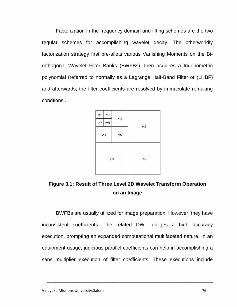
______________________________________________________________________________
Vinayaka Missions University,Salem 76
Factorization in the frequency domain and lifting schemes are the two
regular schemes for accomplishing wavelet decay. The otherworldly
factorization strategy first pre-allots various Vanishing Moments on the Bi-
orthogonal Wavelet Filter Banks (BWFBs), then acquires a trigonometric
polynomial (referred to normally as a Lagrange Half-Band Filter or (LHBF)
and afterwards, the filter coefficients are resolved by immaculate remaking
condtions..
Figure 3.1: Result of Three Level 2D Wavelet Transform Operation
on an Image
BWFBs are usually utilized for image preparation. However, they have
inconsistent coefficients. The related DWT obliges a high accuracy
execution, prompting an expanded computational multifaceted nature. In an
equipment usage, judicious parallel coefficients can help in accomplishing a
sans multiplier execution of filter coefficients. These executions include
______________________________________________________________________________
Vinayaka Missions University,Salem 77
image remaking quality ex-transform offs. Numerous scientists have
additionally confronted the issue of lessening DWT multifaceted nature
[117]. The speciality of this proposed work is that we considered applications
that could make utilization of run-time (not one-time) equipment asset
allotment. To satisfy this necessity, we planned another polymorphic
structural engineering that can empower element control over the properties
of the allotted equipment assets.
Much research has been done in the advancement of DWT
architectures for image processing. A decent review on architectures on
DWT coding is given in [118]. This work gives knowledge on hardware
usage for JPEG2000 scheme, and which takes DWT calculations into
account. The computational many-sided quality investigation of JPEG2000
in [119]. clarifies that EBCOT coding and DWT operations together
contribute more than 80% of the general multifaceted nature. More points of
interest of the JPEG 2000 standard are given in [120].
The DWT architectures can be extensively banded into lifting based,
convolution-based and B-spline based designs. The lifting based
architectures were assimilated into the standard on the grounds that they
require less multipliers and adders and have a normal structure.
Correspondingly, B-spline-based architectures have been proposed to
minimize the quantity of multipliers by utilizing B-spline factorization [121].
______________________________________________________________________________
Vinayaka Missions University,Salem 78
Be that as it may, the lifting based structural engineering has a bigger
discriminating way. Convolution-based methodologies have a lower basic
way, yet oblige a bigger number of multipliers.
3.3 PROPOSED METHODOLOGY
A strategy is developed for executing lifting-based DWT that
diminishes the memory requirements and correspondence between the
processors, when the image is separated into parts. A design is built to
perform lifting based DWT with (5, 3) filter that uses interleaving. For a
framework that comprises the lifting-based DWT transform taken after an
inserted zero-tree calculation, another interleaving scheme is introduced that
decreases the requirement of memory. At long last, a lifting-based DWT
structural planning is devised that fit for performing filters with one lifting
step, i.e., one anticipate and one overhaul step. The yields are produced in
an interleaved manner. The information way is, however, not pipelined.
Interestingly, the four processor building designs proposed here can
perform transforms with a couple of lifting steps, one level at a time. The
entropy coder of JPEG2000 performs the coding in an intra-sub band
design. That means that coefficients in more elevated amounts are not
needed alongside the first level coefficients. Besides, the information way is
pipelined, and the clock period is dictated by the memory access time.
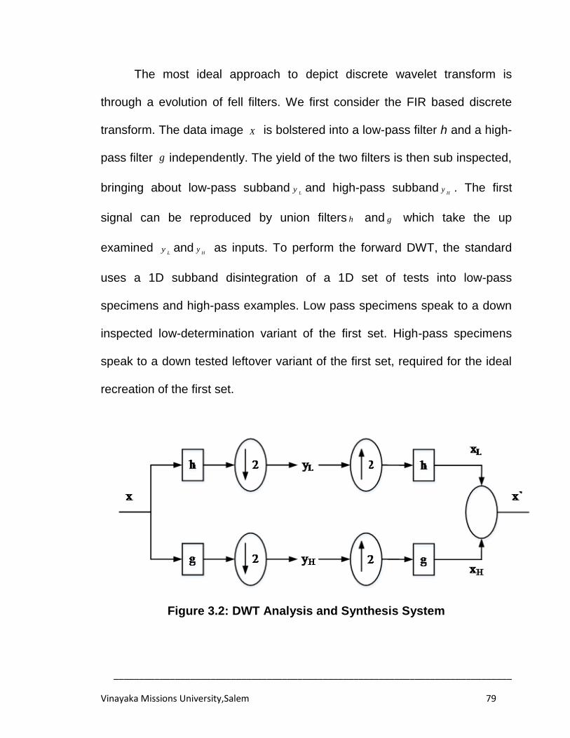
______________________________________________________________________________
Vinayaka Missions University,Salem 79
The most ideal approach to depict discrete wavelet transform is
through a evolution of fell filters. We first consider the FIR based discrete
transform. The data image X is bolstered into a low-pass filter h and a high-
pass filter g independently. The yield of the two filters is then sub inspected,
bringing about low-pass subbandL
y and high-pass subbandH
y . The first
signal can be reproduced by union filters h and g which take the up
examined L
y andH
y as inputs. To perform the forward DWT, the standard
uses a 1D subband disintegration of a 1D set of tests into low-pass
specimens and high-pass examples. Low pass specimens speak to a down
inspected low-determination variant of the first set. High-pass specimens
speak to a down tested leftover variant of the first set, required for the ideal
recreation of the first set.
Figure 3.2: DWT Analysis and Synthesis System
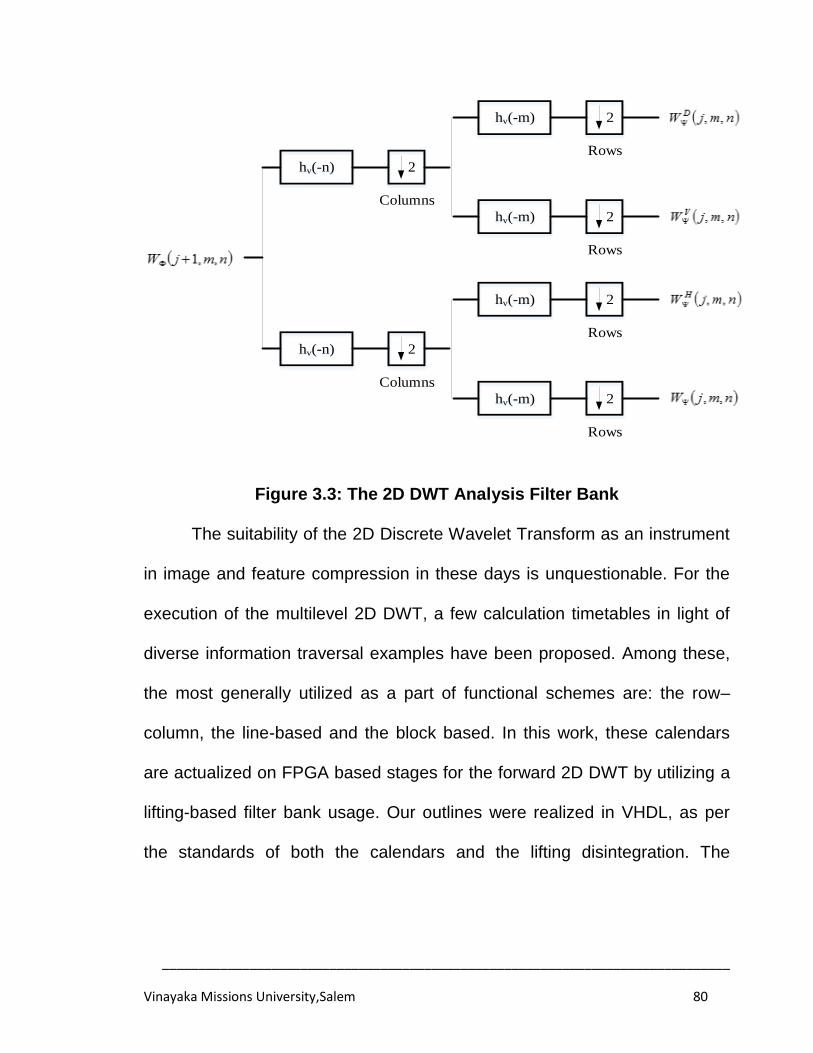
______________________________________________________________________________
Vinayaka Missions University,Salem 80
hv(-n)
hv(-n)
2
2
hv(-m) 2
2hv(-m)
hv(-m) 2
2hv(-m)
Columns
Columns
Rows
Rows
Rows
Rows
Figure 3.3: The 2D DWT Analysis Filter Bank
The suitability of the 2D Discrete Wavelet Transform as an instrument
in image and feature compression in these days is unquestionable. For the
execution of the multilevel 2D DWT, a few calculation timetables in light of
diverse information traversal examples have been proposed. Among these,
the most generally utilized as a part of functional schemes are: the row–
column, the line-based and the block based. In this work, these calendars
are actualized on FPGA based stages for the forward 2D DWT by utilizing a
lifting-based filter bank usage. Our outlines were realized in VHDL, as per
the standards of both the calendars and the lifting disintegration. The
______________________________________________________________________________
Vinayaka Missions University,Salem 81
executions are completely parameterized as far as the measure of the data
image and the quantity of decay level are concerned.
3.3.1 MATHEMATICAL FORMULATION OF DWT
The fundamental rule of the lifting scheme is to factorize the
polyphase network of a wavelet filter into an arrangement of substituting
upper and lower triangular grids and a corner to corner lattice. This prompts
the wavelet usage by a method for joined grid duplications. The foremost
highlight of the lifting based DWT scheme is to separate the high pass and
low pass filters into a banding of upper and lower triangular grids and deliver
the filter execution into united network duplications. Such a scheme has a
few points of interest, including set up processing of the DWT, integer-to-
integer number wavelet transform (IWT), symmetric forward and converse
transform, and so on.
A wavelet 5/3 lifting transform has 3 and 5 taps in the high and low
pass investigation filters separately. 5/3 lifting transform is otherwise called
Le Gall 5/3 transform. Le Gall 5/3 wavelet is the briefest symmetrical bi-
orthogonal wavelet with two vanishing minutes. It is the least complex
approach to break down the image into one high frequency part and one low
frequency segment. The most limited bi-orthogonal scaling and wavelet
capacity with two normality elements at blend and examination signified (2,
2) is accomplished with Le Gall 5/3 combination capacity.
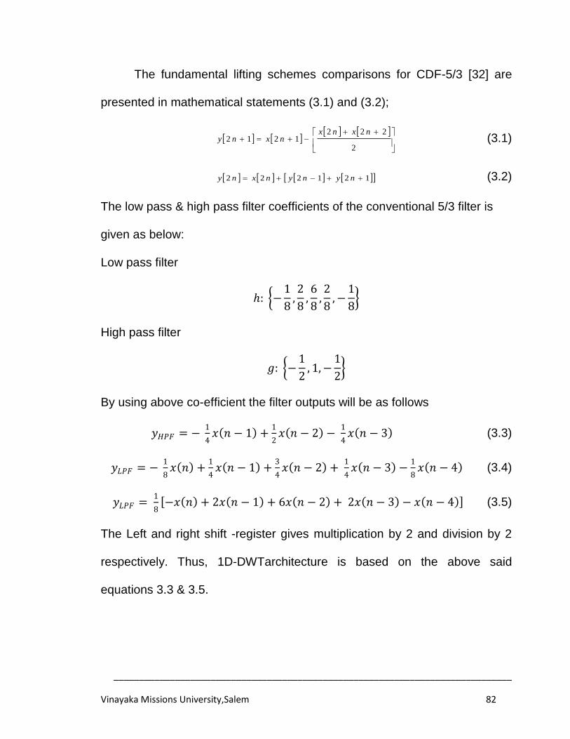
______________________________________________________________________________
Vinayaka Missions University,Salem 82
The fundamental lifting schemes comparisons for CDF-5/3 [32] are
presented in mathematical statements (3.1) and (3.2);
2
2221212
nxnxnxny (3.1)
121222 nynynxny (3.2)
The low pass & high pass filter coefficients of the conventional 5/3 filter is
given as below:
Low pass filter
ℎ: −1
8,2
8,6
8,2
8,−
1
8
High pass filter
𝑔: −1
2, 1,−
1
2
By using above co-efficient the filter outputs will be as follows
𝑦𝐻𝑃𝐹 = − 1
4𝑥 𝑛 − 1 +
1
2𝑥 𝑛 − 2 −
1
4𝑥 𝑛 − 3 (3.3)
𝑦𝐿𝑃𝐹 = − 1
8𝑥 𝑛 +
1
4𝑥 𝑛 − 1 +
3
4𝑥 𝑛 − 2 +
1
4𝑥 𝑛 − 3 −
1
8𝑥 𝑛 − 4 (3.4)
𝑦𝐿𝑃𝐹 = 1
8 −𝑥 𝑛 + 2𝑥 𝑛 − 1 + 6𝑥 𝑛 − 2 + 2𝑥 𝑛 − 3 − 𝑥 𝑛 − 4 (3.5)
The Left and right shift -register gives multiplication by 2 and division by 2
respectively. Thus, 1D-DWTarchitecture is based on the above said
equations 3.3 & 3.5.
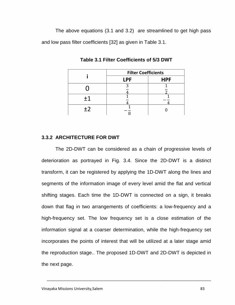
______________________________________________________________________________
Vinayaka Missions University,Salem 83
The above equations (3.1 and 3.2) are streamlined to get high pass
and low pass filter coefficients [32] as given in Table 3.1.
Table 3.1 Filter Coefficients of 5/3 DWT
3.3.2 ARCHITECTURE FOR DWT
The 2D-DWT can be considered as a chain of progressive levels of
deterioration as portrayed in Fig. 3.4. Since the 2D-DWT is a distinct
transform, it can be registered by applying the 1D-DWT along the lines and
segments of the information image of every level amid the flat and vertical
shifting stages. Each time the 1D-DWT is connected on a sign, it breaks
down that flag in two arrangements of coefficients: a low-frequency and a
high-frequency set. The low frequency set is a close estimation of the
information signal at a coarser determination, while the high-frequency set
incorporates the points of interest that will be utilized at a later stage amid
the reproduction stage.. The proposed 1D-DWT and 2D-DWT is depicted in
the next page.
i Filter Coefficients
LPF HPF
0 3
4
1
2
±1 1
4 −
1
4
±2 −1
8 0
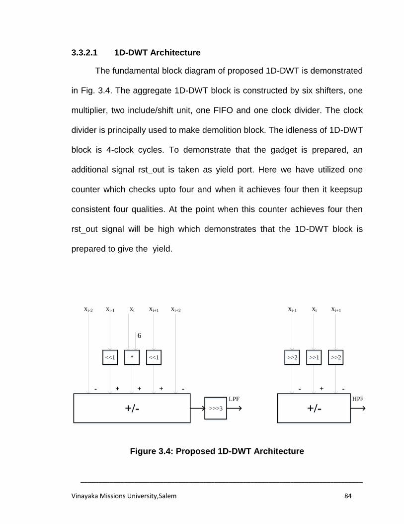
______________________________________________________________________________
Vinayaka Missions University,Salem 84
3.3.2.1 1D-DWT Architecture
The fundamental block diagram of proposed 1D-DWT is demonstrated
in Fig. 3.4. The aggregate 1D-DWT block is constructed by six shifters, one
multiplier, two include/shift unit, one FIFO and one clock divider. The clock
divider is principally used to make demolition block. The idleness of 1D-DWT
block is 4-clock cycles. To demonstrate that the gadget is prepared, an
additional signal rst_out is taken as yield port. Here we have utilized one
counter which checks upto four and when it achieves four then it keepsup
consistent four qualities. At the point when this counter achieves four then
rst_out signal will be high which demonstrates that the 1D-DWT block is
prepared to give the yield.
+/-
<<1 * <<1
>>>3
LPF
+/-
>>2>>1>>2
HPF
-- ++++- -
6
xi xi+1 xi+2xi-1xi-2 xi xi+1xi-1
Figure 3.4: Proposed 1D-DWT Architecture
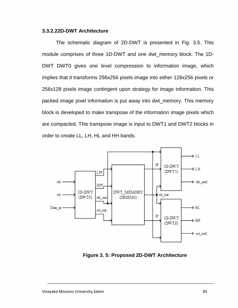
______________________________________________________________________________
Vinayaka Missions University,Salem 85
3.3.2.22D-DWT Architecture
The schematic diagram of 2D-DWT is presented in Fig. 3.5. This
module comprises of three 1D-DWT and one dwt_memory block. The 1D-
DWT DWT0 gives one level compression to information image, which
implies that it transforms 256x256 pixels image into either 128x256 pixels or
256x128 pixels image contingent upon strategy for image information. This
packed image pixel information is put away into dwt_memory. This memory
block is developed to make transpose of the information image pixels which
are compacted. This transpose image is input to DWT1 and DWT2 blocks in
order to create LL, LH, HL and HH bands.
Figure 3. 5: Proposed 2D-DWT Architecture
______________________________________________________________________________
Vinayaka Missions University,Salem 86
3.4 IMPLEMENTATION RESULTS AND DISCUSSIONS
The functional schematic diagram of 2D-DWT was presented in Fig.
3.5. This module comprises three 1D-DWT and one „dwt_memory‟ block as
detailed earlier.
The yield image of 1D-DWT is obtainable in Fig. 3.6, which has a size
of 128x256 of two bands (named as L and H ). The yield image of 2D-DWT
is revealed in Fig. 3.7 which has a size of 128x128 of four bands (named as
LL , LH HL and HH bands).
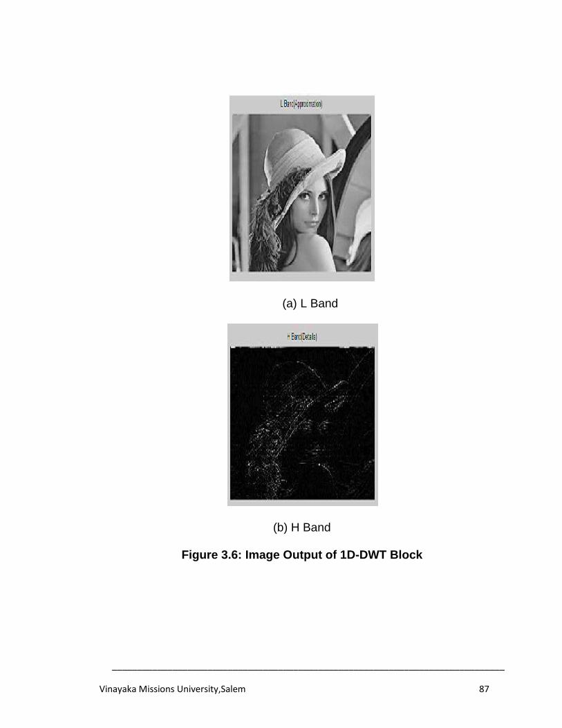
______________________________________________________________________________
Vinayaka Missions University,Salem 87
(a) L Band
(b) H Band
Figure 3.6: Image Output of 1D-DWT Block
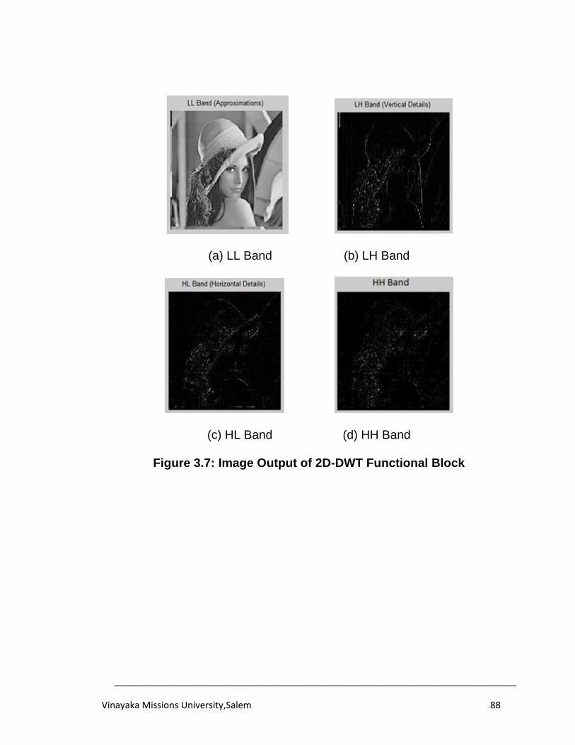
______________________________________________________________________________
Vinayaka Missions University,Salem 88
(a) LL Band (b) LH Band
(c) HL Band (d) HH Band
Figure 3.7: Image Output of 2D-DWT Functional Block
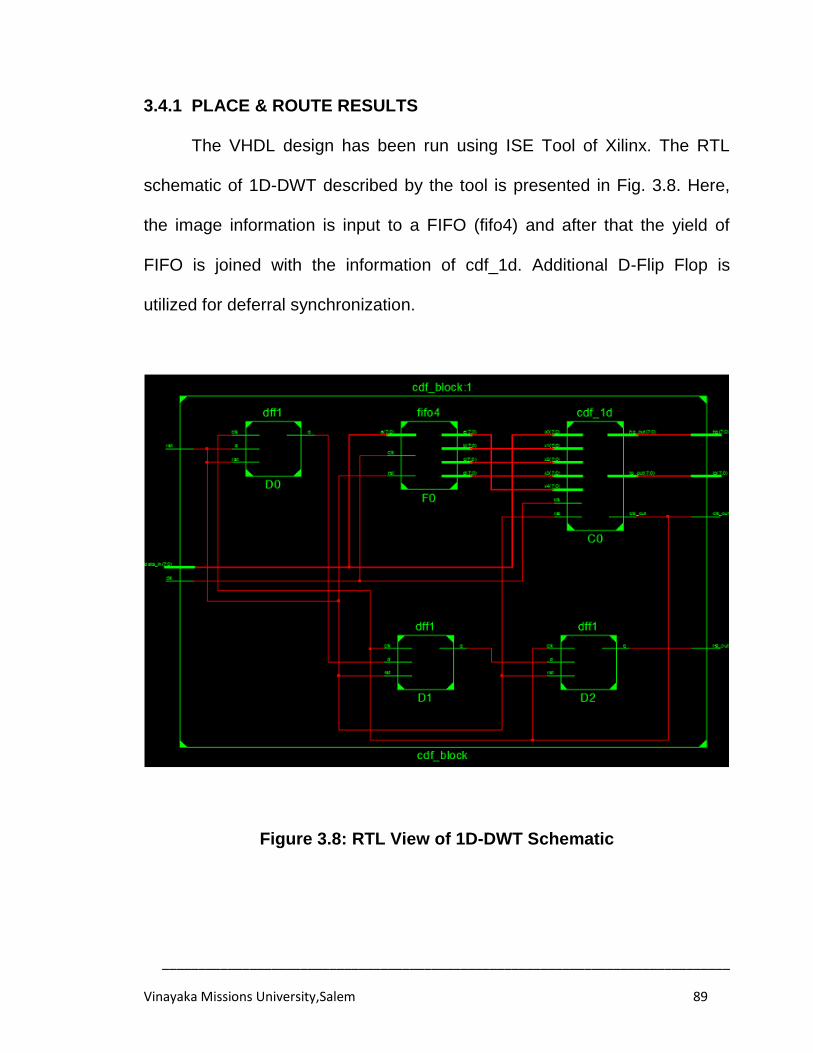
______________________________________________________________________________
Vinayaka Missions University,Salem 89
3.4.1 PLACE & ROUTE RESULTS
The VHDL design has been run using ISE Tool of Xilinx. The RTL
schematic of 1D-DWT described by the tool is presented in Fig. 3.8. Here,
the image information is input to a FIFO (fifo4) and after that the yield of
FIFO is joined with the information of cdf_1d. Additional D-Flip Flop is
utilized for deferral synchronization.
Figure 3.8: RTL View of 1D-DWT Schematic
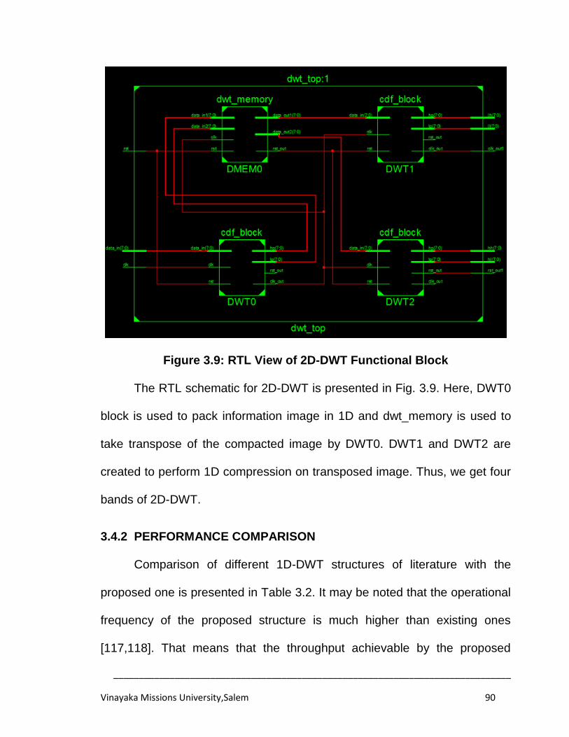
______________________________________________________________________________
Vinayaka Missions University,Salem 90
Figure 3.9: RTL View of 2D-DWT Functional Block
The RTL schematic for 2D-DWT is presented in Fig. 3.9. Here, DWT0
block is used to pack information image in 1D and dwt_memory is used to
take transpose of the compacted image by DWT0. DWT1 and DWT2 are
created to perform 1D compression on transposed image. Thus, we get four
bands of 2D-DWT.
3.4.2 PERFORMANCE COMPARISON
Comparison of different 1D-DWT structures of literature with the
proposed one is presented in Table 3.2. It may be noted that the operational
frequency of the proposed structure is much higher than existing ones
[117,118]. That means that the throughput achievable by the proposed
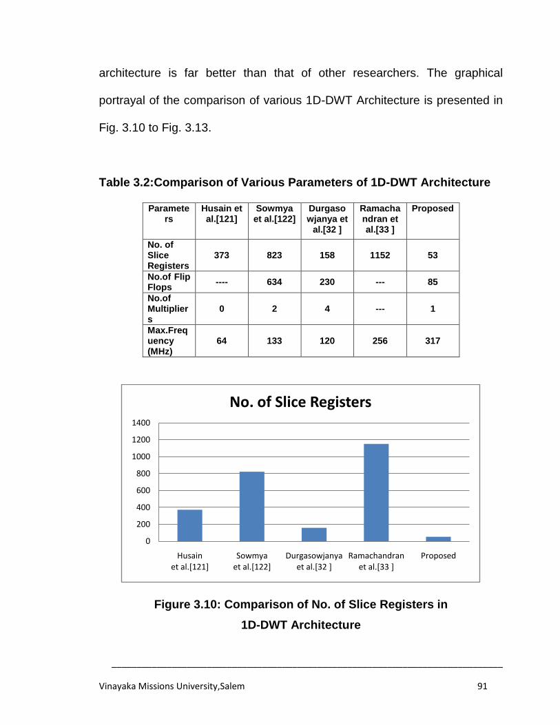
______________________________________________________________________________
Vinayaka Missions University,Salem 91
architecture is far better than that of other researchers. The graphical
portrayal of the comparison of various 1D-DWT Architecture is presented in
Fig. 3.10 to Fig. 3.13.
Table 3.2:Comparison of Various Parameters of 1D-DWT Architecture
Parameters
Husain et al.[121]
Sowmya et al.[122]
Durgasowjanya et
al.[32 ]
Ramachandran et al.[33 ]
Proposed
No. of Slice Registers
373 823 158 1152 53
No.of Flip Flops
---- 634 230 --- 85
No.of Multipliers
0 2 4 --- 1
Max.Frequency (MHz)
64 133 120 256 317
Figure 3.10: Comparison of No. of Slice Registers in
1D-DWT Architecture
0
200
400
600
800
1000
1200
1400
Husain et al.[121]
Sowmya et al.[122]
Durgasowjanya et al.[32 ]
Ramachandran et al.[33 ]
Proposed
No. of Slice Registers
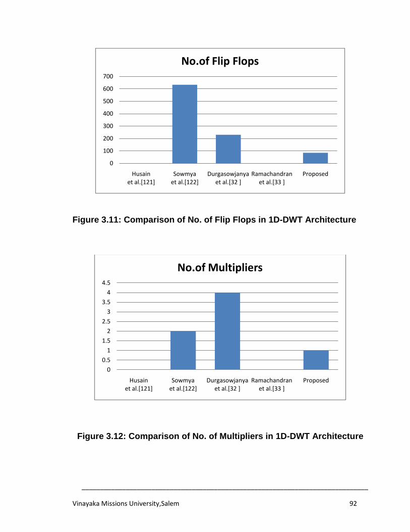
______________________________________________________________________________
Vinayaka Missions University,Salem 92
Figure 3.11: Comparison of No. of Flip Flops in 1D-DWT Architecture
Figure 3.12: Comparison of No. of Multipliers in 1D-DWT Architecture
0
100
200
300
400
500
600
700
Husain et al.[121]
Sowmya et al.[122]
Durgasowjanya et al.[32 ]
Ramachandran et al.[33 ]
Proposed
No.of Flip Flops
0
0.5
1
1.5
2
2.5
3
3.5
4
4.5
Husain et al.[121]
Sowmya et al.[122]
Durgasowjanya et al.[32 ]
Ramachandran et al.[33 ]
Proposed
No.of Multipliers
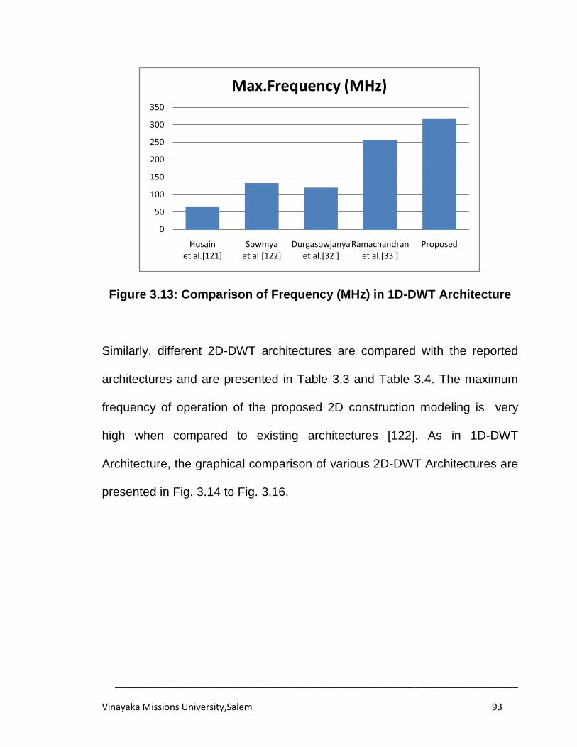
______________________________________________________________________________
Vinayaka Missions University,Salem 93
Figure 3.13: Comparison of Frequency (MHz) in 1D-DWT Architecture
Similarly, different 2D-DWT architectures are compared with the reported
architectures and are presented in Table 3.3 and Table 3.4. The maximum
frequency of operation of the proposed 2D construction modeling is very
high when compared to existing architectures [122]. As in 1D-DWT
Architecture, the graphical comparison of various 2D-DWT Architectures are
presented in Fig. 3.14 to Fig. 3.16.
0
50
100
150
200
250
300
350
Husain et al.[121]
Sowmya et al.[122]
Durgasowjanya et al.[32 ]
Ramachandran et al.[33 ]
Proposed
Max.Frequency (MHz)
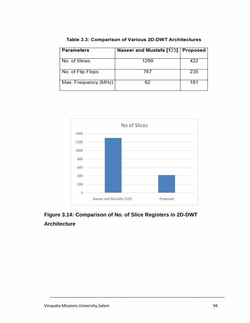
______________________________________________________________________________
Vinayaka Missions University,Salem 94
Figure 3.14: Comparison of No. of Slice Registers in 2D-DWT
Architecture
0
200
400
600
800
1000
1200
1400
Naseer and Mustafa [119] Proposed
No of Slices
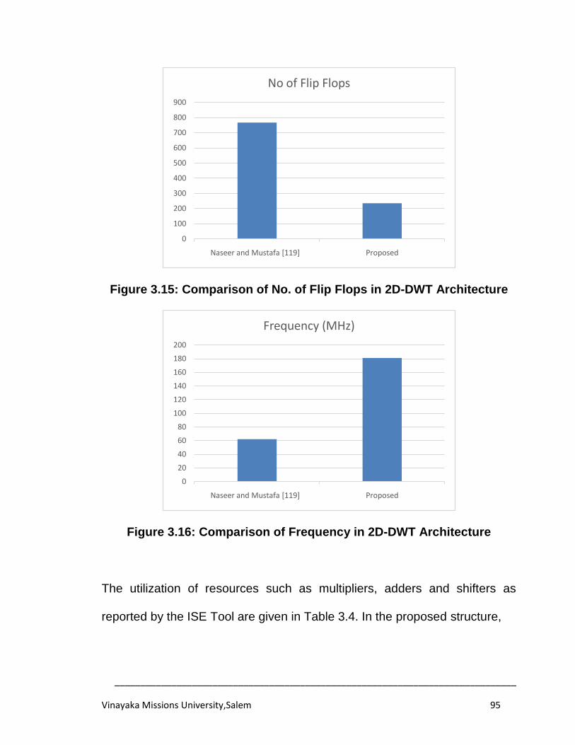
______________________________________________________________________________
Vinayaka Missions University,Salem 95
Figure 3.15: Comparison of No. of Flip Flops in 2D-DWT Architecture
Figure 3.16: Comparison of Frequency in 2D-DWT Architecture
The utilization of resources such as multipliers, adders and shifters as
reported by the ISE Tool are given in Table 3.4. In the proposed structure,
0
100
200
300
400
500
600
700
800
900
Naseer and Mustafa [119] Proposed
No of Flip Flops
0
20
40
60
80
100
120
140
160
180
200
Naseer and Mustafa [119] Proposed
Frequency (MHz)
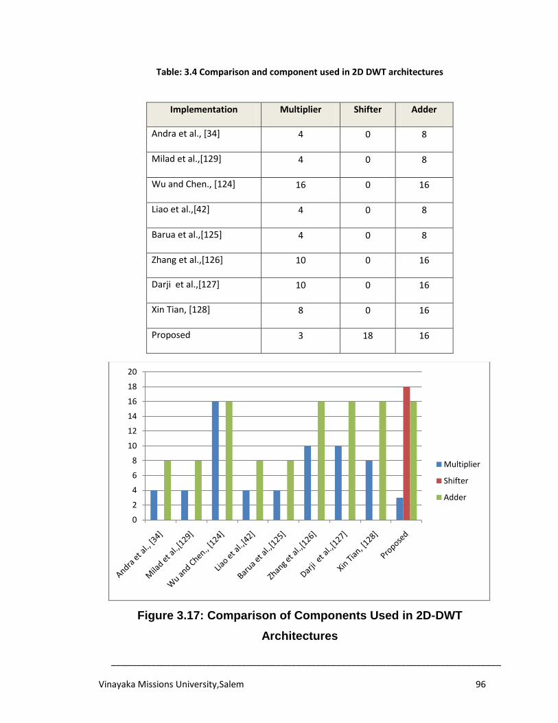
______________________________________________________________________________
Vinayaka Missions University,Salem 96
Table: 3.4 Comparison and component used in 2D DWT architectures
Figure 3.17: Comparison of Components Used in 2D-DWT
Architectures
0
2
4
6
8
10
12
14
16
18
20
Multiplier
Shifter
Adder
Implementation Multiplier Shifter Adder
Andra et al., [34] 4 0 8
Milad et al.,[129] 4 0 8
Wu and Chen., [124] 16 0 16
Liao et al.,[42] 4 0 8
Barua et al.,[125] 4 0 8
Zhang et al.,[126] 10 0 16
Darji et al.,[127] 10 0 16
Xin Tian, [128] 8 0 16
Proposed 3 18 16
______________________________________________________________________________
Vinayaka Missions University,Salem 97
The number of multipliers and adders used are less, yet the number of
shifters is more. Since shifters are made by trading with wire numbers, so no
extra hardware is required. The resource utilization of the 2D-DWT
architectures by various researchers are graphically presented in Fig. 3.17.
SUMMARY
An effective VLSI Architecture for lifting based 5/3 DWT has been
projected. The 1D-DWT lift structure has been composed efficiently by using
a minimum of multipliers and adders. The proposed 1D-DWT is also utilized
to outline efficient 2D lift based 5/3 DWT Architecture. It was targeted on
Virtex-IV FPGA in order to assess various parameters like number of Slices,
LUT's, and maximum frequency of operation. It is observed that the
proposed architectural realization is better contrasted with existing models
contributed by other Researchers.
______________________________________________________________________________
Vinayaka Missions University,Salem 98
CHAPTER 4
DEVELOPMENT OF ALGORITHM FOR DWT-SPIHT AND THEIR
INVERSES FOR IMAGE COMPRESSION
In the previous chapter, a novel DWT Architecture was presented and
its implementation was analyzed. Those investigations demonstrated that
the proposed 5/3 DWT method is well suited for image compression in terms
of FPGA resources. In this chapter, we intend to develop an algorithms for
Discrete Wavelet Transform and Set Partitioning in Hierarchical Trees
(SPIHT) and their inverses such that it is conducive for the design of an
image Codec. This chapter also presents MATLAB implementation for DWT-
SPIHT- ISPIHT- IDWT image compression. The developed MATLAB code is
executed on 2D images and the results are evaluated in terms of PSNR and
Compression Ratio achieved.
4.1 INTRODUCTION
As one of the key-empowering advancements in sight and sound
communications, image compression has wide and vital applications in our
everyday lives. The two key strategies: Discrete Wavelet Transform and
SPIHT have awesome impact on its implementation; therefore they have got
more consideration before.
______________________________________________________________________________
Vinayaka Missions University,Salem 99
As a lossy image compression algorithm, Discrete Cosine Transform
was the centre of JPEG global models and was a standout amongst the then
developments. At the point when the compression proportion is under 10:1,
the DCT-based JPEG image compression won't have critical impact on
geometry highlights. Be that as it may, under the state of substantial
compression proportion, it will create the blocking antiques and the blocking
artifacts truly. Wavelet gives a decent answer for this issue of blocking
artifacts and DWT has turned out to be the most outstanding tool for image
compression in the course of the recent two decades [130--137].
With the point of accomplishing rate adaptability, there has beena
developing groupon wavelet based imagecompression. Inreality,Shapiro‟s
Embedded Zero TreeWavelet (EZW)coder inviewofanoteworthinesstree
quantization,abuses the likenesses betweenthesubbands in thewavelet
transform location and the vitality‟s appropriationof images through the
subbands.Once DWT was brought into action, many codec algorithms were
introduced to compress the transform coefficients however much as could
be expected. Among those, Stationary Waveform Transform (SWT) and Set
Partitioning in Hierarchical Trees (SPIHT) are the widespread ones[138]. An
enhanced interpretation of EZW by Said and Pearlman [136], known as Set
Partitioning in Hierarchical Trees (SPIHT), stands out amongst the most
productive wavelet-based image compression algorithms. As opposed to
______________________________________________________________________________
Vinayaka Missions University,Salem 100
EZW-based coding, where a tree is apportioned once it is observed to be
huge, SPIHT expect that the noteworthy test consequence of any tree is
prone to be from its immediate relatives. In this manner, if a set is observed
to be critical, just its immediate relatives are encoded and a noteworthiness
test will be performed on its non-direct relatives. The set is kept non-
parceled until one of its non-direct relatives is observed to be critical [136]. In
this way, the observed SPIHT algorithm is the most capable and the least
complex of all coders, extendable to distinctive sorts of computerized
information and alluring for hardware implementations[137]. Notwithstanding
the prerequisite on the coding implementation, rate versatility is further seen
as a standout amongst the most significant properties to be accomplished in
the configuration of the most recent image compression plans [139].
Image compression assumes a critical part in numerous essential and
differing applications, including tele-video-conferencing, remote detection,
therapeutic imaging, facsimile transmission and control applications. The
interactive media information compression methods, for example, JPEG,
JPEG2000 and MPEG focus on accomplishing high compression without
sacrificing on the quality.
The fundamental premise of the lessening procedure is the
evacuation of excess information. From a scientific perspective, this adds up
to changing a 2D pixel cluster into a measurably uncorrelated information
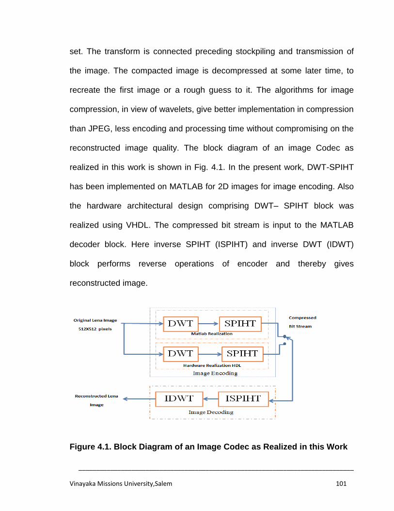
______________________________________________________________________________
Vinayaka Missions University,Salem 101
set. The transform is connected preceding stockpiling and transmission of
the image. The compacted image is decompressed at some later time, to
recreate the first image or a rough guess to it. The algorithms for image
compression, in view of wavelets, give better implementation in compression
than JPEG, less encoding and processing time without compromising on the
reconstructed image quality. The block diagram of an image Codec as
realized in this work is shown in Fig. 4.1. In the present work, DWT-SPIHT
has been implemented on MATLAB for 2D images for image encoding. Also
the hardware architectural design comprising DWT– SPIHT block was
realized using VHDL. The compressed bit stream is input to the MATLAB
decoder block. Here inverse SPIHT (ISPIHT) and inverse DWT (IDWT)
block performs reverse operations of encoder and thereby gives
reconstructed image.
Figure 4.1. Block Diagram of an Image Codec as Realized in this Work
______________________________________________________________________________
Vinayaka Missions University,Salem 102
4.2 WAVELET IMAGE COMPRESSION
Managing colossal measure of data can regularly show troubles.
Computerized data must be put away and recovered in an efficient way with
the goal of putting it to functional utilization. Wavelet compression is one
approach to manage this issue.
The Fingerprint Binary Image utilizes wavelet compression to help
store and recover its unique mark documents. It has more than 25 million
cards, every card containing 10 unique mark impressions. To store the
greater part of the cards would require more than 250 terabytes of space.
Without some kind of compression, sorting, putting away, and hunting down
information would be unthinkable. Utilizing wavelets, the Fingerprint Binary
Image acquires a compression of around 20. The strides expected to pack
an image are as per the following:
1. Digitize the source image into a sign s, which is a series of numbers.
2. Decompose the sign into a succession of wavelet coefficients w.
3. Use thresholding to alter the wavelet coefficients from w to another
arrangement w'.
4. Use quantization to transform over w' to a grouping q.
5. Apply entropy coding to pack q into a grouping e.
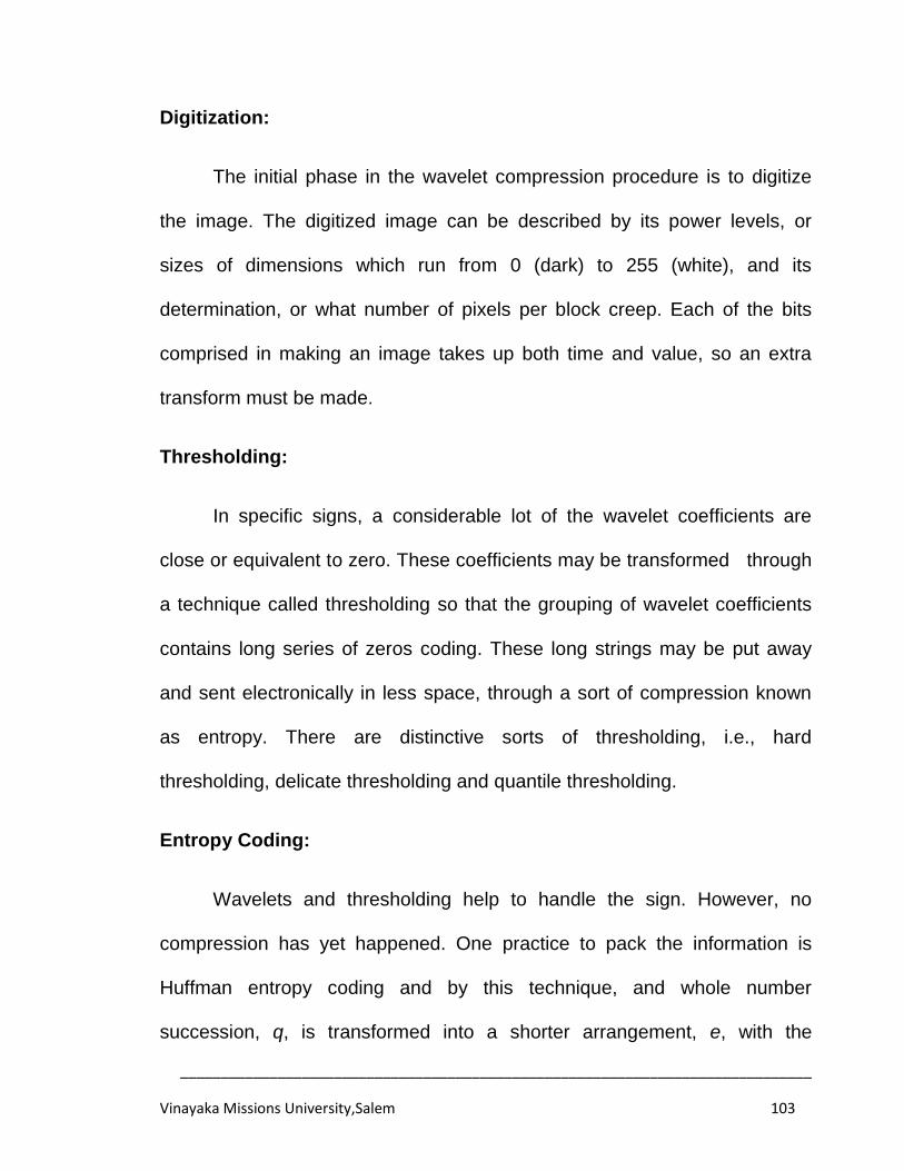
______________________________________________________________________________
Vinayaka Missions University,Salem 103
Digitization:
The initial phase in the wavelet compression procedure is to digitize
the image. The digitized image can be described by its power levels, or
sizes of dimensions which run from 0 (dark) to 255 (white), and its
determination, or what number of pixels per block creep. Each of the bits
comprised in making an image takes up both time and value, so an extra
transform must be made.
Thresholding:
In specific signs, a considerable lot of the wavelet coefficients are
close or equivalent to zero. These coefficients may be transformed through
a technique called thresholding so that the grouping of wavelet coefficients
contains long series of zeros coding. These long strings may be put away
and sent electronically in less space, through a sort of compression known
as entropy. There are distinctive sorts of thresholding, i.e., hard
thresholding, delicate thresholding and quantile thresholding.
Entropy Coding:
Wavelets and thresholding help to handle the sign. However, no
compression has yet happened. One practice to pack the information is
Huffman entropy coding and by this technique, and whole number
succession, q, is transformed into a shorter arrangement, e, with the

______________________________________________________________________________
Vinayaka Missions University,Salem 104
numbers in e being 8 bit numbers. The transform is made by an entropy
coding table. Series of zeros are coded by the numbers 1 through 100, 105,
and 106, while the non-zero whole numbers in q are coded by 101 through
104 and 107 through 254. In Huffman entropy coding, the concept is to
utilize a less number for coding, in which the first being used as a flag
indicating a massive number or a long zero arrangement is progressing.
Quantization:
The fourth stride of the procedure, known as quantization, transforms
over an arrangement of coasting numbers w' to a grouping of whole
numbers q. The least complex structure is to round to the closest whole
number. Another choice is to increase every number in w' by a consistent k,
and after that round to the closest whole number. Quantization is called
lossy in light of the fact that it brings slip in the procedure, since the
transformation of w' to q is not a coordinated capacity.
Daubechies Wavelets:
In order to prepare an image with a specific end goal, symmetric
biorthogonal wavelets are utilized. These have two father and two mother
wavelets, and are needed with a specific end goal to pack a network of
information. The Daubechies wavelet family is the most broadly utilized
wavelet for image compression, with six coefficients and biorthogonality.
______________________________________________________________________________
Vinayaka Missions University,Salem 105
Deslauriers Wavelets:
Deslauriers wavelets are additionally symmetric biorthogonal
wavelets. We utilized this arrangement of wavelets for the transform of our
image.
The initial phase in the wavelet compression procedure is to digitize
the image. The digitized image can be portrayed by its power levels, or sizes
that range from 0 (dark) to 255 (white), and its determination, or what
number of pixels per block creep. The wavelets handle the sign, as has
been mentioned before.
The next step is quantization which converts a sequence of floating
numbers to a sequence of integers. The simplest form is to round to the
nearest integer. Another option is to multiply each number by a constant and
then round to the nearest integer. Quantization is called lossy because it
introduces error into the process, since the conversion is not a one-to-one
function.
The last step is encoding that is in charge of the real compression.
The block diagram for Wavelet Coder and Decoder are presented in Fig. 4.2
and Fig. 4.3 respectively. A regular image compression framework
comprising three firmly associated segments: (i) Source Transformer (ii)
Quantizer and (iii) Entropy Encoder and is presented in Fig. 4.2.
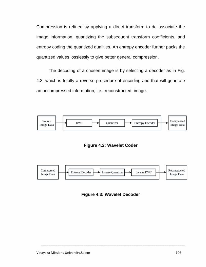
______________________________________________________________________________
Vinayaka Missions University,Salem 106
Compression is refined by applying a direct transform to de associate the
image information, quantizing the subsequent transform coefficients, and
entropy coding the quantized qualities. An entropy encoder further packs the
quantized values losslessly to give better general compression.
The decoding of a chosen image is by selecting a decoder as in Fig.
4.3, which is totally a reverse procedure of encoding and that will generate
an uncompressed information, i.e., reconstructed image.
Source
Image DataDWT Quantizer Entropy Encoder
Compressed
Image Data
Figure 4.2: Wavelet Coder
Reconstructed
Image DataInverse DWTInverse Quantizer Entropy Decoder
Compressed
Image Data
Figure 4.3: Wavelet Decoder
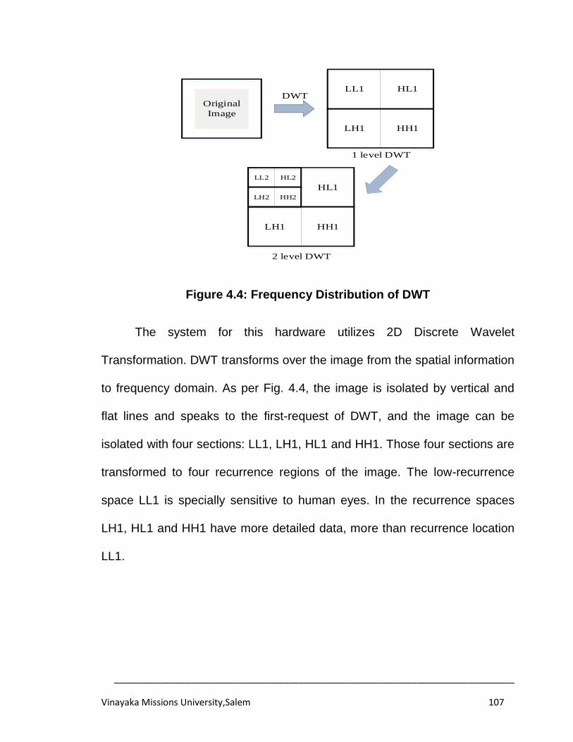
______________________________________________________________________________
Vinayaka Missions University,Salem 107
Original
Image
DWTLL1 HL1
HH1LH1
HL1
HH1LH1
HH2
LL2 HL2
LH2
1 level DWT
2 level DWT
Figure 4.4: Frequency Distribution of DWT
The system for this hardware utilizes 2D Discrete Wavelet
Transformation. DWT transforms over the image from the spatial information
to frequency domain. As per Fig. 4.4, the image is isolated by vertical and
flat lines and speaks to the first-request of DWT, and the image can be
isolated with four sections: LL1, LH1, HL1 and HH1. Those four sections are
transformed to four recurrence regions of the image. The low-recurrence
space LL1 is specially sensitive to human eyes. In the recurrence spaces
LH1, HL1 and HH1 have more detailed data, more than recurrence location
LL1.
______________________________________________________________________________
Vinayaka Missions University,Salem 108
4.3 SPIHT ALGORITHM
Set Partitioning in Hierarchical Trees has turned out to be the best
benchmark in class algorithm for image compression. SPIHT is
computationally very fast and best among the available image compression
algorithms[140].SPIHT algorithm along with lifting concepts was used to
compress the images. Superior low bit rate presentation, bit level
compression, resolution, progressive transmission by pixel and accuracy
were the results of tests conducted [141].
The strategy merits extraordinary consideration on the grounds that it
offers the following salient features:
1. Highest Image Quality.
2. Progressive image transmission.
3. Fully embedded coded file.
4. Simple quantization algorithm.
5. Fast coding/decoding.
6. Completely adaptive.
7. Near lossless compression.
8. Exact bit rate coding and
9. Error protection.
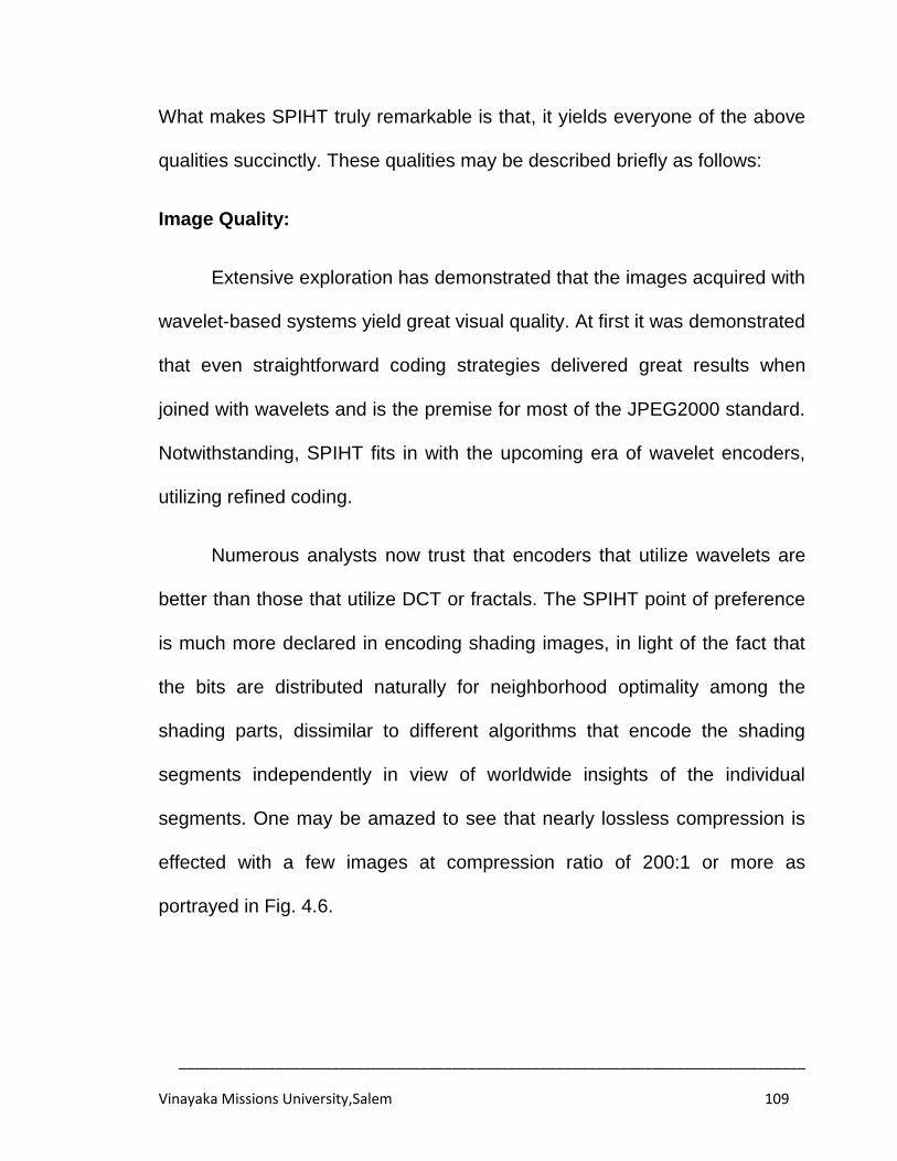
______________________________________________________________________________
Vinayaka Missions University,Salem 109
What makes SPIHT truly remarkable is that, it yields everyone of the above
qualities succinctly. These qualities may be described briefly as follows:
Image Quality:
Extensive exploration has demonstrated that the images acquired with
wavelet-based systems yield great visual quality. At first it was demonstrated
that even straightforward coding strategies delivered great results when
joined with wavelets and is the premise for most of the JPEG2000 standard.
Notwithstanding, SPIHT fits in with the upcoming era of wavelet encoders,
utilizing refined coding.
Numerous analysts now trust that encoders that utilize wavelets are
better than those that utilize DCT or fractals. The SPIHT point of preference
is much more declared in encoding shading images, in light of the fact that
the bits are distributed naturally for neighborhood optimality among the
shading parts, dissimilar to different algorithms that encode the shading
segments independently in view of worldwide insights of the individual
segments. One may be amazed to see that nearly lossless compression is
effected with a few images at compression ratio of 200:1 or more as
portrayed in Fig. 4.6.
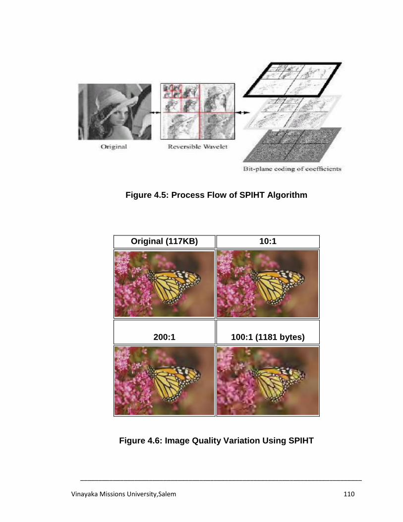
______________________________________________________________________________
Vinayaka Missions University,Salem 110
Figure 4.5: Process Flow of SPIHT Algorithm
Original (117KB) 10:1
200:1
100:1 (1181 bytes)
Figure 4.6: Image Quality Variation Using SPIHT
______________________________________________________________________________
Vinayaka Missions University,Salem 111
Progressive Image Transmission:
Progressive image transmission can help reduce the latency when
transmitting raster images over low bandwidth links. Often, a rough estimate
(preview) of an image is sufficient for the user to decide whether or not it
should be transmitted in greater aspect. During image refinement, the
requested greater level of detail can quite often be limited to certain
provinces of the image (regions of interest). We distinguish between the
refinement methods detail on demand, where the user requests greater
detail, and progressive refinement, where the system transmits and displays
more detail automatically. Both methods can be combined, too. In order to
save bandwidth, it is critical that only differential data are transmitted.
Progressive image transmission provides a convenient user interface
when images are transmitted slowly. When persons see an image through a
low speed connection, for example, via a telephone line or via wireless
networks, it will take greater time to transmit the whole image. Transmitting a
losslessly compressed 800x600 pixels 24-bit colour image over a 56 Kbps
connection will require about 60 secs. Even with enlarged bandwidth,
transmitting big images such as pictures captured by digital cameras is still
relatively slow. Experiments have shown that if the delay is too long (>5-
10s), user will feel nervous and even give up. Progressive Image
Transmission (PIT) techniques have been suggested to alleviate this
______________________________________________________________________________
Vinayaka Missions University,Salem 112
problem by first sending a coarse version of the original image and then
refining it progressively. Using PIT, users can preview the image in advance
and therefore decide whether to abort the transferring process or wait for the
image to be refined. PIT is especially useful for tele-browsing, tele-medicine
and mobile applications.
4.4 PROPOSED DWT-SPIHT ALGORITHM
Taking wavelets into account , the most efficient algorithm is Set
Partitioning in Hierarchical Trees (SPIHT) algorithm among new for the
image compression This algorithm bases its proficiency in key ideas like: a)
fractional requesting of wavelet coefficients by extent, with transmission of
request by a subset dividing that is reproduced at the decoder, b) requested
bit-plane transmission of refinement bits and c) abuse of self-likeness of the
image wavelet coefficients crosswise over distinctive scales.
Generally it makes use a subband coder, to carry a pyramid structure
where an image is deteriorated repeatedly by applying force to
corresponding low pass and high pass channels and after that obliterating
the subsequent images. These one-dimensional channels that are
connected in cascade to an image whereby making four-way deterioration:
LL, LH, HL and HH. The subsequent LL form is again four-way decayed.
This procedure is rehashed until the highest point of the pyramid is come to.
______________________________________________________________________________
Vinayaka Missions University,Salem 113
There exists a spatial relationship among the coefficients at distinctive levels
and recurrence sub-groups in the pyramid structure.
On the other extreme, SPIHT is a state-of-the-art process that was
intended for optimal progressive transmission (and still beats most non
progressive methods). It does so by producing a fully embedded coded file
(as can be seen in the following), in a method that at any moment the quality
of the displayed image is the best available for the number of bits received
up to that moment. Thus, SPIHT can be very useful for applications where
the user can speedily inspect the image and decide if it should be really
taken, or is good enough to be saved, or need refinement.
The terms and notations used in SPIHT algorithm is as follows:
• C (i, j): wavelet transformed coefficient at coordinate (i, j).
• O (i, j): set of coordinates of all offspring of node (i, j); children only.
• D (i, j): set of coordinates of all descendants of node (i, j) children,
Grand children etc.
• L (i, j): set of coordinates of all leaves of node (i, j). L(i, j) = D(i, j) - O(i, j)
Grand children etc.
______________________________________________________________________________
Vinayaka Missions University,Salem 114
• H(I, j): set of coordinates of all nodes in the coarsest level of wavelet
coefficient pyramid; parents
• Sn(i, j): significance test of a set of coordinates {(i, j)}
The location ji , in the pyramid representation has four immediate
relatives (off-springs) at locations:
1111
2,2,2,2,2,2,2,2,
jijijiji
jiO (4.1)
Each of them recursively keeps up a spatial likeness to its comparing
four off-spring. This pyramid structure is regularly known as spatial
introduction tree. In the event that a given coefficient at location ji , is
critical in size then some of its relatives will likewise presumably be huge in
size. The SPIHT algorithm exploits the spatial closeness exhibit in the
wavelet space to ideally discover the location of the wavelet coefficient that
is noteworthy by method for a parallel pursuit algorithm.
The SPIHT algorithm propels the top coefficients in the pyramid
structure using a progressive transmission scheme. This system is a method
that allows means to obtain a high quality version of the original image from
the minimal amount of transmitted data.
As shown in Table 4.1, the pyramid wavelet coefficients are requested
by greatness and after that the most critical bits are transmitted initially,
______________________________________________________________________________
Vinayaka Missions University,Salem 115
trailed by the following bit plane and so on,until the least bit plane is reached
at. It has been demonstrated that dynamic transmission can fundamentally
diminish the Mean Block Error (MSE) twisting for each bit-plane sent.
To exploit the spatial relationship among the coefficients at diverse
levels and recurrence groups, the SPIHT coder algorithm arranges the
wavelets coefficient as per the centrality test characterized as:
n
jimcji 2,max
, (4.2)
Where ji
c,
is the wavelet coefficient at the nth bit plane, at location
ji , of the m
subset of pixels, speaking to a guardian hub and its relatives.
On the off chance that the after effect of the hugeness test is yes, an S
banner is set to 1 showing that a specific test is huge. On the off chance that
the answer is no, then the S banner is set to 0, showing that the specific
coefficient is immaterial. This is indicated by mathematical statement (4.3).
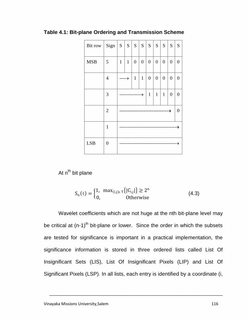
______________________________________________________________________________
Vinayaka Missions University,Salem 116
Table 4.1: Bit-plane Ordering and Transmission Scheme
Bit row Sign S S S S S S S S S
MSB 5 1 1 0 0 0 0 0 0 0
4 ---- 1 1 0 0 0 0 0
3 ------------- 1 1 1 0 0
2 ------------------------------ 0
1 -----------------------------------
LSB 0 -----------------------------------
At nth
bit plane
Sn = 1, max i,j T |Ci,j| ≥ 2n
0, Otherwise (4.3)
Wavelet coefficients which are not huge at the nth bit-plane level may
be critical at (n-1)th bit-plane or lower. Since the order in which the subsets
are tested for significance is important in a practical implementation, the
significance information is stored in three ordered lists called List Of
Insignificant Sets (LIS), List Of Insignificant Pixels (LIP) and List Of
Significant Pixels (LSP). In all lists, each entry is identified by a coordinate (i,
______________________________________________________________________________
Vinayaka Missions University,Salem 117
j) which in the LIP and LSP represents individual pixels and in the LIS
represents either to the set D (I, j) or L (I, j). To differentiate between them, it
can be concluded that a LIS entry is of type A if it represents D (i,j) and of
type B if it represents L(I, j). During the sorting pass, the pixels in the LIP,
which were insignificant in the previous pass, are tested and those that
become significant are moved to the LSP. Similarly, sets are sequentially
evaluated following the LIS order, and when a set is found to be significant it
is removed from the list and partitioned. The new subsets with more than
one element are added back to the LIS, while the single coordinate sets are
added.
In the decoder, the SPIHT algorithm imitates the same number of
records. It utilizes the fundamental rule that if the implementation way of any
algorithm is characterized by the outcomes on its expanding focuses, and if
the encoder and decoder have the same sorting algorithm, then the decoder
can recoup the requesting data effortlessly.
Optimized Embedded Coding:
If two brochures created by the encoder have size MxN bits, with M >
N, then the record with size N is indistinguishable with the first N bits of the
record with size M. Let the system has to pack an image for three remote
clients, each client has distinctive needs of image propagation quality and,
those qualities can be acquired with the image compacted to not less than8
______________________________________________________________________________
Vinayaka Missions University,Salem 118
Kb, 30 Kb, and 80 Kb individually. In the event that system can utilize a non-
inserted encoder (like JPEG) to spare transmission expenses (or time), it
must set up one record for every client. On the possibility that system utilizes
an implanted encoder (like SPIHT), it can then pack the image to a solitary
80 Kb document and after that send the initial 8 Kb of the record to the first
client, the initial 30 Kb to the second client, and the entire record to the third
client.
With SPIHT every one of the three clients would get (for the same
record measure) an image quality practically identical or better than the most
modern non-inserted encoders accessible today. SPIHT accomplishes this
deed by upgrading the inserted coding procedure and continually coding the
most vital data first.
A much more essential application is for dynamic image transmission,
where the client can choose and soon thereafter the image quality fulfils his
needs, or prematurely ends the transmission after a snappy investigation,
and so forth. An example of Optimized Embedded Coding is shown in Fig.
4.7.
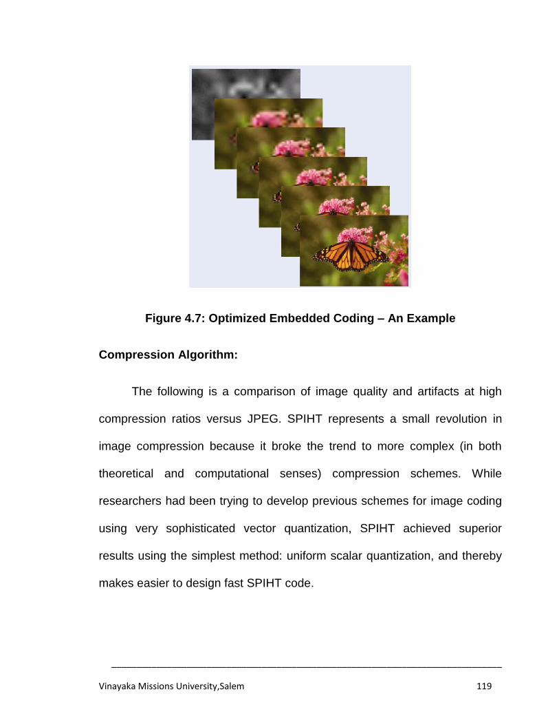
______________________________________________________________________________
Vinayaka Missions University,Salem 119
Figure 4.7: Optimized Embedded Coding – An Example
Compression Algorithm:
The following is a comparison of image quality and artifacts at high
compression ratios versus JPEG. SPIHT represents a small revolution in
image compression because it broke the trend to more complex (in both
theoretical and computational senses) compression schemes. While
researchers had been trying to develop previous schemes for image coding
using very sophisticated vector quantization, SPIHT achieved superior
results using the simplest method: uniform scalar quantization, and thereby
makes easier to design fast SPIHT code.
______________________________________________________________________________
Vinayaka Missions University,Salem 120
Encoding/Decoding Speed:
The SPIHT process represents a very real form of entropy coding.
This is shown by the demo programs using two forms of coding: binary
uncoded (extremely simple) and context-based adaptive arithmetic coded
(sophisticated). Surprisingly, the difference in compression is small, showing
that it is not necessary to use slow methods (and also pay royalties for
them). A fast version using Huffman codes was also positively tested, but it
is not publicly available.
The SPIHT technique is nearly symmetric, i.e., the time to encode is
nearly equal to the time to decode. (Complex compression algorithms incline
to have encoding times much higher than decoding time. Any compression
system uses one of the encoding techniques to encode the input
information. The encoding operation is very vital for the success of the
compression system. It involves the representation of the input information
in a form suitable for storage and transmission. The time required to perform
this operation is referred to as encoding time. The reverse process to
encoding is decoding and the corresponding time required to decode an
encoded data is decoding time. In general, the information to be
compressed will be represented in time or spatial domain. To compress the
data, it was observed that it is convenient to represent the data in frequency
______________________________________________________________________________
Vinayaka Missions University,Salem 121
domain. Hence the information in time domain needs to be converted into
frequency domain. For that, one of the transforming techniques will be used.
The following describes the algorithm developed in the present work:
Step1: In the sorting pass, the List of Insignificant Pixel (LIP) is scanned to
determine whether an entry is significant at the current threshold. If an entry
is found to be significant, output a bit „1‟ and another bit for the sign of the
coefficient, which is marked by either „1‟ for the positive or „0‟ for the
negative. Now the significant entry is moved to the list of significant pixel
(LSP). If an entry in LIP is insignificant, a bit „0‟ is output.
Step2: Entries in List of Insignificant Set (LIS) are processed. When an entry
is the set of all descendants of a coefficient, named „type A‟, magnitude tests
for all descendants of the current entry are carried out to decide whether
they are significant or not. If the entry is found to be significant, the direct
offspring‟s of the entry undergoes magnitude tests. If direct offspring is
significant, it is moved into LIP; otherwise it is moved into LSP. If the entry is
deemed to be insignificant, this spatial orientation tree rooted by the current
entry was a zero-tree, so a bit „0‟ is output and no further processing is
needed. Finally, this entry is moved to the end of LIS as „type B‟, which is
the set of all descendants except for the immediate offspring of a coefficient.
If the entry in LIS is type B, significance test is performed on the
descendants of its direct offspring. If significance test is true, the spatial
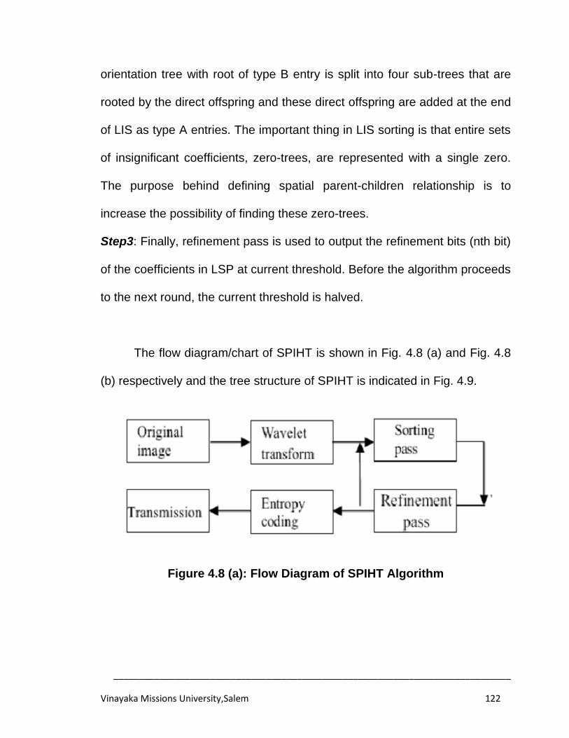
______________________________________________________________________________
Vinayaka Missions University,Salem 122
orientation tree with root of type B entry is split into four sub-trees that are
rooted by the direct offspring and these direct offspring are added at the end
of LIS as type A entries. The important thing in LIS sorting is that entire sets
of insignificant coefficients, zero-trees, are represented with a single zero.
The purpose behind defining spatial parent-children relationship is to
increase the possibility of finding these zero-trees.
Step3: Finally, refinement pass is used to output the refinement bits (nth bit)
of the coefficients in LSP at current threshold. Before the algorithm proceeds
to the next round, the current threshold is halved.
The flow diagram/chart of SPIHT is shown in Fig. 4.8 (a) and Fig. 4.8
(b) respectively and the tree structure of SPIHT is indicated in Fig. 4.9.
Figure 4.8 (a): Flow Diagram of SPIHT Algorithm
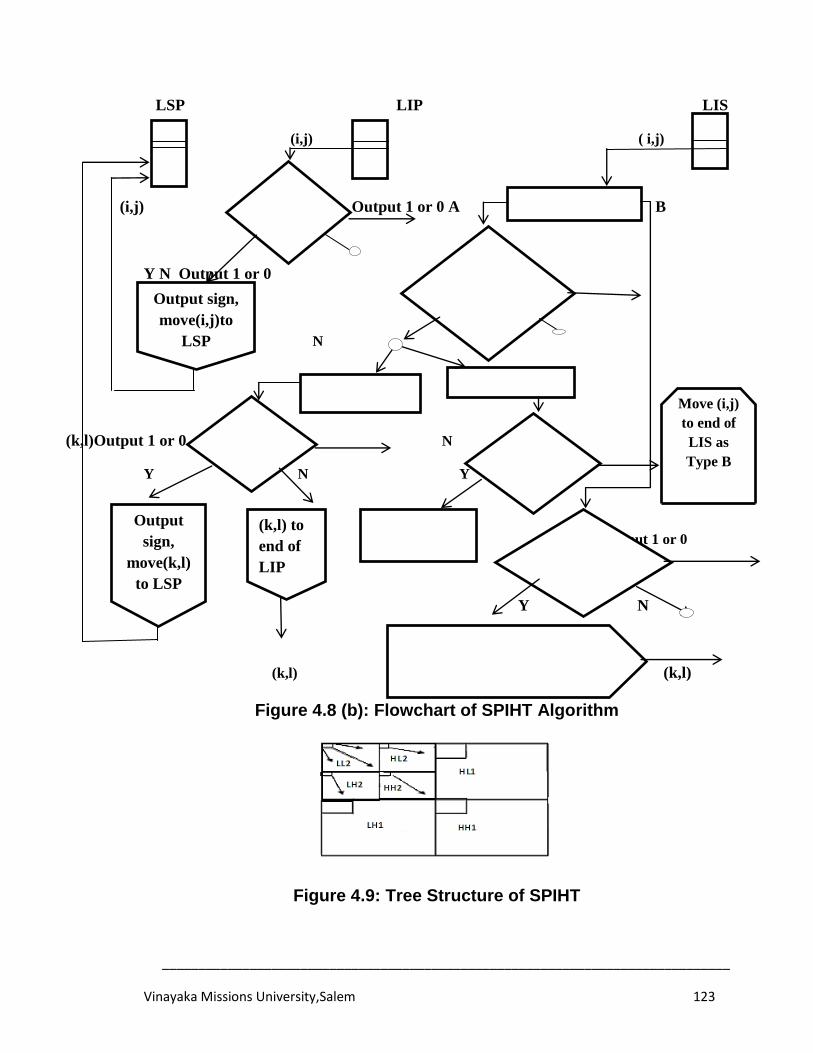
______________________________________________________________________________
Vinayaka Missions University,Salem 123
LSP LIP LIS
(i,j) ( i,j)
(i,j) Output 1 or 0 A B
Y N Output 1 or 0
Y N
(k,l)Output 1 or 0 N
Y N Y
Output 1 or 0
Y N
(k,l) (k,l)
Figure 4.8 (b): Flowchart of SPIHT Algorithm
Figure 4.9: Tree Structure of SPIHT
|c(i,j)|
≥ 2n
Max in
L(i,j) ≥ 2n
Max in
D(i,j) ≥ 2n
Type A or B?
(k,l) in O(i,j)to end of LIS as
Type A; Remove (i,j) from LIS
L(i,j) (k,l) in O(i,j)
|c(k,l) |
≥ 2n
L(I,j)=
ɸ?
Remove (i,j)
from LIS
Output sign,
move(i,j)to
LSP
Output
sign,
move(k,l)
to LSP
(k,l) to
end of
LIP
Move (i,j)
to end of
LIS as
Type B
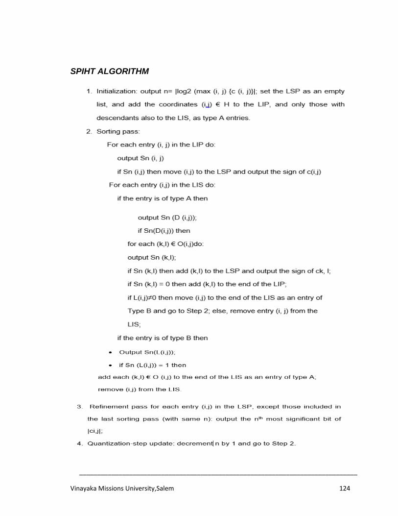
______________________________________________________________________________
Vinayaka Missions University,Salem 124
SPIHT ALGORITHM
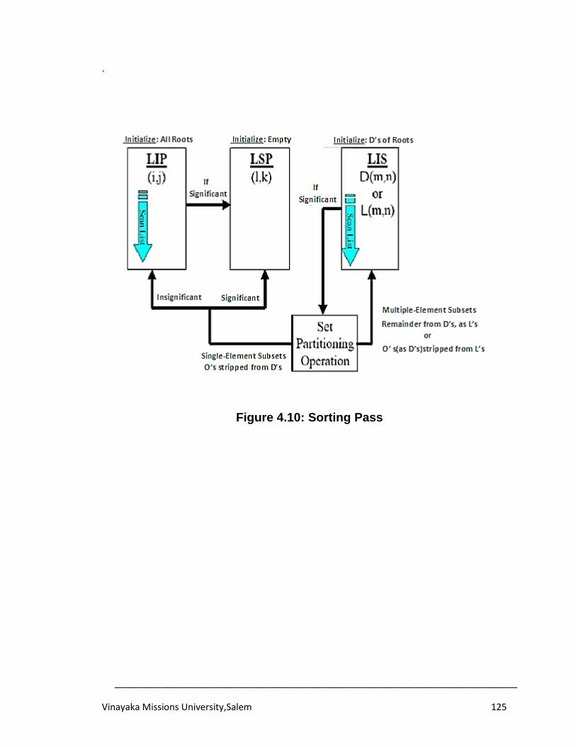
______________________________________________________________________________
Vinayaka Missions University,Salem 125
`
Figure 4.10: Sorting Pass
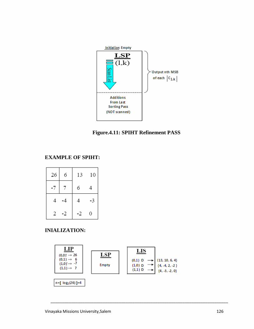
______________________________________________________________________________
Vinayaka Missions University,Salem 126
Figure.4.11: SPIHT Refinement PASS
EXAMPLE OF SPIHT:
INIALIZATION:
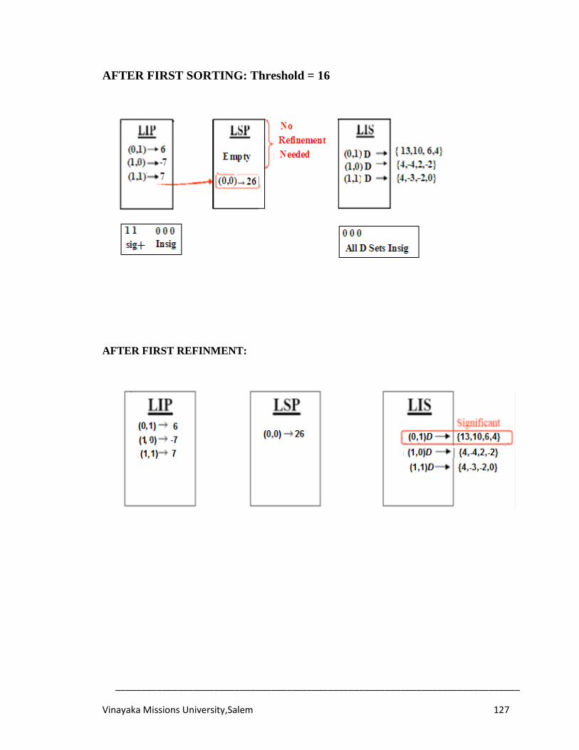
______________________________________________________________________________
Vinayaka Missions University,Salem 127
AFTER FIRST SORTING: Threshold = 16
AFTER FIRST REFINMENT:
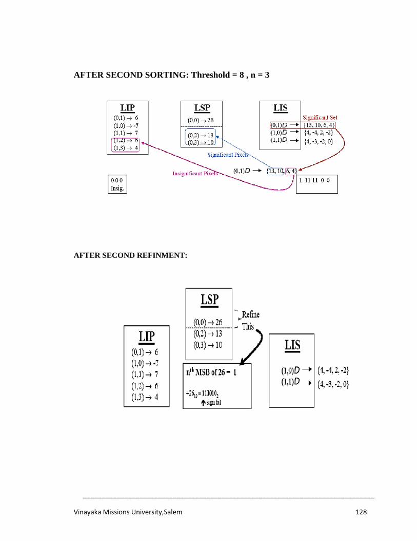
______________________________________________________________________________
Vinayaka Missions University,Salem 128
AFTER SECOND SORTING: Threshold = 8 , n = 3
AFTER SECOND REFINMENT:
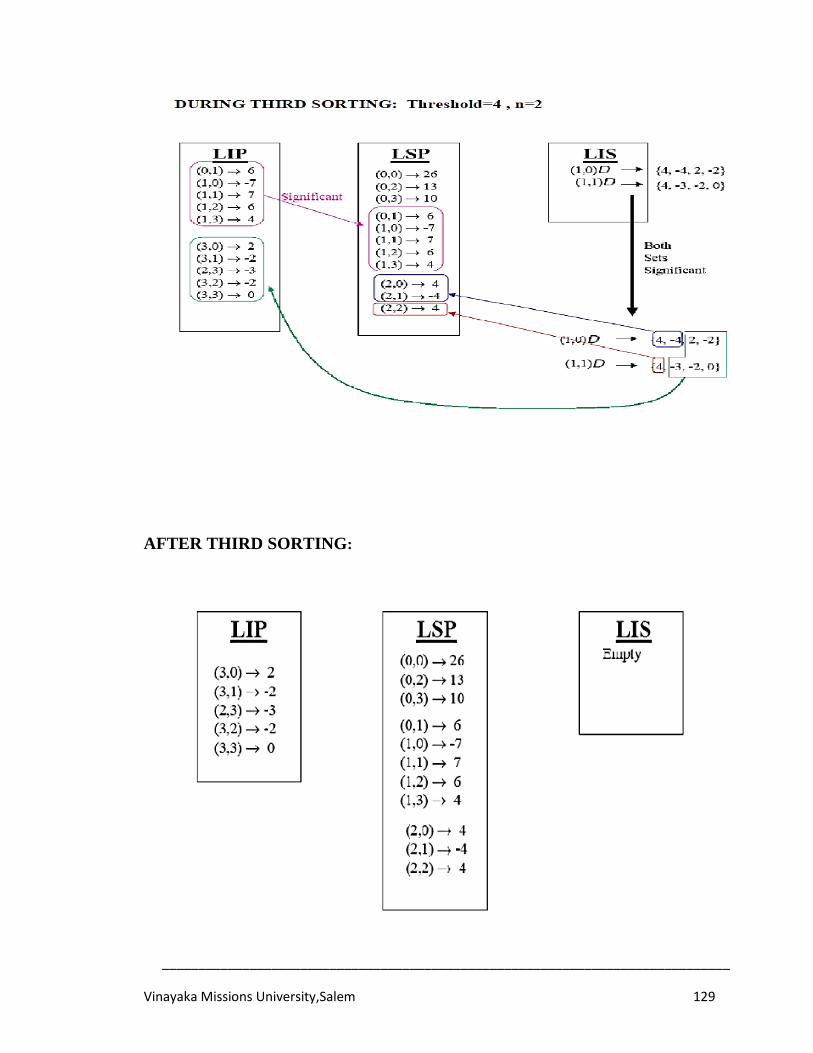
______________________________________________________________________________
Vinayaka Missions University,Salem 129
AFTER THIRD SORTING:
______________________________________________________________________________
Vinayaka Missions University,Salem 130
4.5 IMPLEMENTATION RESULTS AND DISCUSSIONS
The proposed algorithm was simulated using MATLAB on different
color images of 512 X 512 pixels sizes with the following metrics to evaluate
the image quality.
Mean Squared Error (MSE):
It refers to some sort of average or sum (or integral) of squares of the
error between two images as shown in Eq. (4.4).
𝑀𝑆𝐸 =1
𝑀𝑁 | 𝐼 𝑖, 𝑗 − 𝐾 𝑖, 𝑗 |𝑛−1
𝑗=0𝑚−1𝑖=0 (4.4)
Where I (i, j) is the original image data and K(i, j) isthe compressed image
data.
2 Peak Signal to Noise Ratio (PSNR):
This is defined as the ratio between signal variance and
reconstruction error variance. Peak Signal to Noise Ratio is calculated from
the following Eq. (4.5).
𝑃𝑆𝑁𝑅 = 10 log((255)2/𝑀𝑆𝐸) (4.5)
3 Compression Ratio (CR):
Compression ratio is defined as the ratio between the original image
size (n1) and compressed image size (n2) as in Eq. (4.6).
𝐶𝑅 = 𝑛1/𝑛2 (4.6)
4 Coding Time:
It is the total time taken for the image compression and decompression.
______________________________________________________________________________
Vinayaka Missions University,Salem 131
In this segment, the image is transformed utilizing one level 2D
Wavelet Transform. The1D wavelet transform can be stretched out to a two-
dimensional (2D) wavelet transform utilizing detachable wavelet channels.
The 2D transform can be registered by applying a 1D transform and is
applied to every one of the lines of the information, and after that rehashing
is carried out on the majority of the sections. The image is altered into
frequency coefficients as LL (low-pass then another low pass), LH (low pass
then high pass), HL (high and low pass) and finally HH (high pass then
another high pass). The subsequent LL rendition is again deteriorated to
give a decayed image.
The approval of an image utilizing diverse wavelets are measured
values, for example, Encoding time, Decoding time, compression proportion
and the estimation of PSNR for distinctive wavelets. The acceptance is to
get to give out the implementation and the estimation of an image quality
decay.
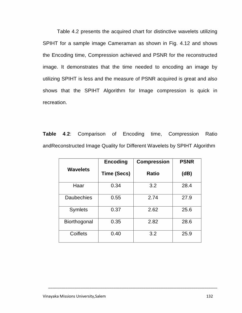
______________________________________________________________________________
Vinayaka Missions University,Salem 132
Table 4.2 presents the acquired chart for distinctive wavelets utilizing
SPIHT for a sample image Cameraman as shown in Fig. 4.12 and shows
the Encoding time, Compression achieved and PSNR for the reconstructed
image. It demonstrates that the time needed to encoding an image by
utilizing SPIHT is less and the measure of PSNR acquired is great and also
shows that the SPIHT Algorithm for Image compression is quick in
recreation.
Table 4.2: Comparison of Encoding time, Compression Ratio
andReconstructed Image Quality for Different Wavelets by SPIHT Algorithm
Wavelets
Encoding
Time (Secs)
Compression
Ratio
PSNR
(dB)
Haar 0.34 3.2 28.4
Daubechies 0.55 2.74 27.9
Symlets 0.37 2.62 25.6
Biorthogonal 0.35 2.82 28.6
Coiflets 0.40 3.2 25.9
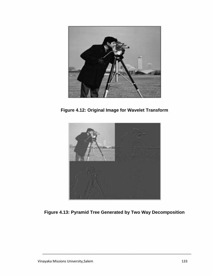
______________________________________________________________________________
Vinayaka Missions University,Salem 133
Figure 4.12: Original Image for Wavelet Transform
Figure 4.13: Pyramid Tree Generated by Two Way Decomposition
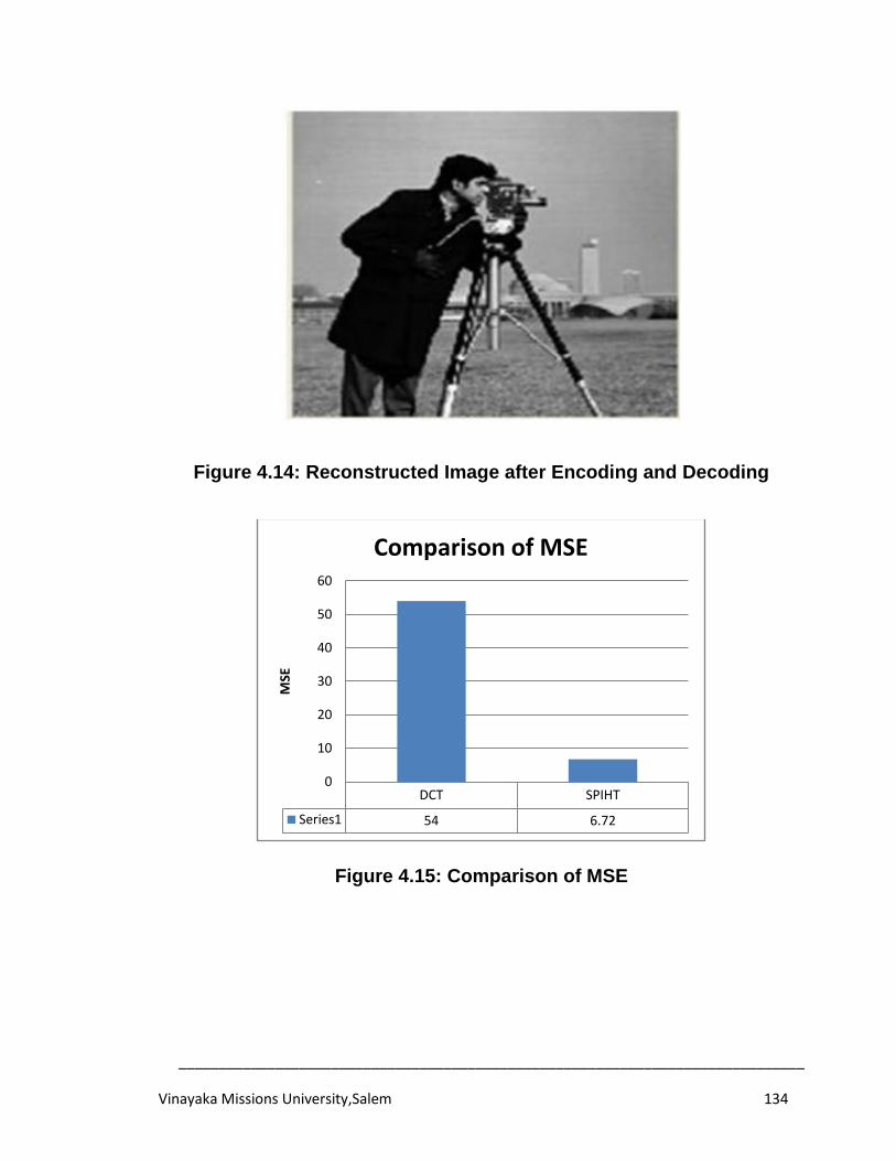
______________________________________________________________________________
Vinayaka Missions University,Salem 134
Figure 4.14: Reconstructed Image after Encoding and Decoding
Figure 4.15: Comparison of MSE
DCT SPIHT
Series1 54 6.72
0
10
20
30
40
50
60
MSE
Comparison of MSE
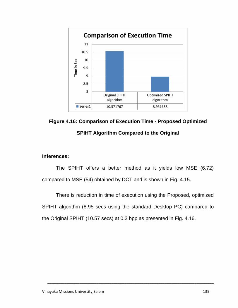
______________________________________________________________________________
Vinayaka Missions University,Salem 135
Figure 4.16: Comparison of Execution Time - Proposed Optimized
SPIHT Algorithm Compared to the Original
Inferences:
The SPIHT offers a better method as it yields low MSE (6.72)
compared to MSE (54) obtained by DCT and is shown in Fig. 4.15.
There is reduction in time of execution using the Proposed, optimized
SPIHT algorithm (8.95 secs using the standard Desktop PC) compared to
the Original SPIHT (10.57 secs) at 0.3 bpp as presented in Fig. 4.16.
Original SPIHT algorithm
Optimized SPIHT algorithm
Series1 10.571767 8.951688
8
8.5
9
9.5
10
10.5
11
Tim
e in
Se
c
Comparison of Execution Time
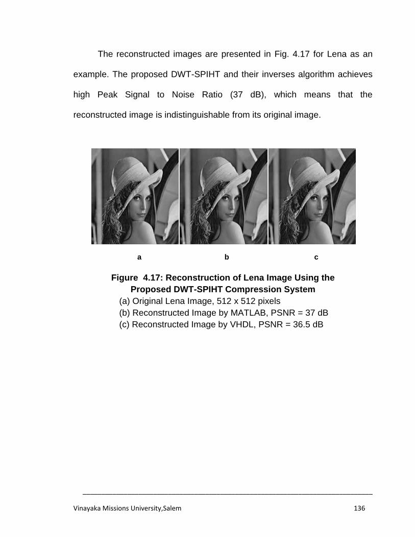
______________________________________________________________________________
Vinayaka Missions University,Salem 136
The reconstructed images are presented in Fig. 4.17 for Lena as an
example. The proposed DWT-SPIHT and their inverses algorithm achieves
high Peak Signal to Noise Ratio (37 dB), which means that the
reconstructed image is indistinguishable from its original image.
a b c
Figure 4.17: Reconstruction of Lena Image Using the
Proposed DWT-SPIHT Compression System
(a) Original Lena Image, 512 x 512 pixels
(b) Reconstructed Image by MATLAB, PSNR = 37 dB
(c) Reconstructed Image by VHDL, PSNR = 36.5 dB
______________________________________________________________________________
Vinayaka Missions University,Salem 137
SUMMARY
In this chapter, an optimized algorithm has been developed for DWT-
SPIHT and Their Inverses for an Iimage Codec and validated using
MATLAB program. The reconstructed image is close to the original image.
The results demonstrate that the visual quality can be kept up in transmitting
feature arrangements at low bit rate (200 kbps) over the channel of high
information in a transmitting gadget. The proposed image Codec is made
versatile by changing parameters to specific wavelet transform level,
disposal level and quantization level. This recreation uncovered a certainty
that DWT-SPIHT is quite efficient. Using the Proposed SPIHT algorithm, it
can be observed that the Encoding time is small and the reconstructed
quality is better than the original SPIHT Algorithm. The reconstructed image
such as Lena is visually very close to the original image with a quality factor
of 37 dB. The compression effected was 0.3 bits per pixel, which means that
the original image has been compressed by 27 times. Therefore the
proposed system of implementation is practical, adaptable and offers high
processing speed without sacrificing on the image quality.
______________________________________________________________________________
Vinayaka Missions University,Salem 138
CHAPTER 5
WAVELET BASED VIDEO ENCODER
In last two chapters the systems for the image compression utilizing
5/3 DWT and SPIHT based DWT was given. The section three gives the
novel methodology for the FPGA implementation of 2D-DWT image
compression. The section four gives the novel procedure for the image
compression utilizing SPIHT. The outline and usage of adaptable hardware
building design for the DWT based video encoder is displayed in this
section. The encoder is demonstrated utilizing MATLAB and VHDL. The
VHDL model is re-enacted utilizing the Xilinx XST and ISIM Simulator. DWT
core is utilized as a part of conjunction with an exceptionably straightforward
number-crunching coder for quick and productive to show the capacity of the
encoder in the zone of video compression. This section, concentrates on the
DWT utilizing 9/7 filter, which gives great compression quality, yet is
especially difficult to execute with high effectiveness because of the
unreasonable way of the filter coefficients. The structural planning has been
coded in VHDL using Xilinx software and the objective FPGA gadget utilized
is Virtex-IV Pro gang. So this building design is feasible for continuous
handling of DWT reckoning applications.
______________________________________________________________________________
Vinayaka Missions University,Salem 139
5.1 INTRODUCTION
The expanding development of innovation and the passageway into
the advanced age, we need to handle a boundless measure of data each
time which frequently displays challenges. Video compression is the
procedure of encoding data utilizing less bits. Compression is valuable in
light of the fact that it serves to decrease the utilization of extravagant
assets, for example, hard circle space or transmission data transfer
capacity. The video is really a sort of repetitive information i.e. it contains the
same data from certain viewpoint of perspective. It is possible to evacuate a
portion of the repetitive data contained in images. Image compression
minimizes the size in bytes of an illustrations document without corrupting
the nature of the image to an unsuitable level. The diminishment in record
size permits more images to be put away in a certain measure of circle or
memory.
The compression offers intend to decrease the expense of capacity
and expand the velocity of transmission. Video compression is utilized to
minimize the span of a video record without degrading the nature of the
video. In the course of recent years, a mixed bag of capable and modern
wavelet based plans for image and video compression have been produced
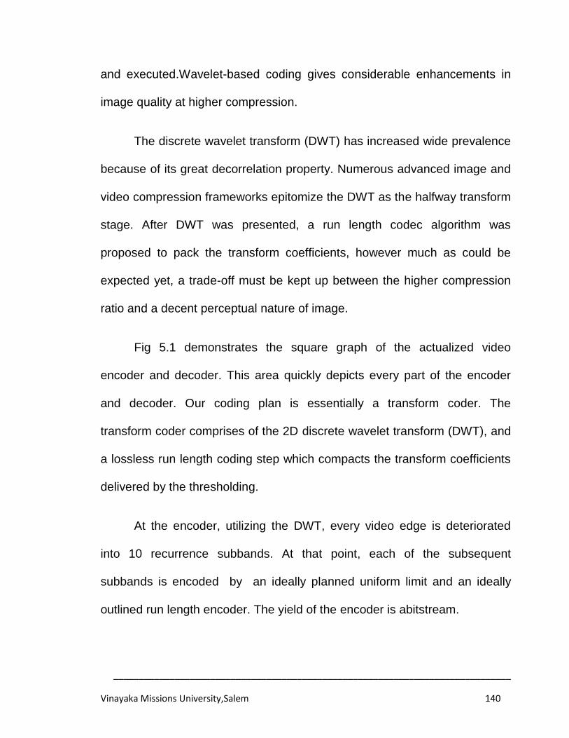
______________________________________________________________________________
Vinayaka Missions University,Salem 140
and executed.Wavelet-based coding gives considerable enhancements in
image quality at higher compression.
The discrete wavelet transform (DWT) has increased wide prevalence
because of its great decorrelation property. Numerous advanced image and
video compression frameworks epitomize the DWT as the halfway transform
stage. After DWT was presented, a run length codec algorithm was
proposed to pack the transform coefficients, however much as could be
expected yet, a trade-off must be kept up between the higher compression
ratio and a decent perceptual nature of image.
Fig 5.1 demonstrates the square graph of the actualized video
encoder and decoder. This area quickly depicts every part of the encoder
and decoder. Our coding plan is essentially a transform coder. The
transform coder comprises of the 2D discrete wavelet transform (DWT), and
a lossless run length coding step which compacts the transform coefficients
delivered by the thresholding.
At the encoder, utilizing the DWT, every video edge is deteriorated
into 10 recurrence subbands. At that point, each of the subsequent
subbands is encoded by an ideally planned uniform limit and an ideally
outlined run length encoder. The yield of the encoder is abitstream.
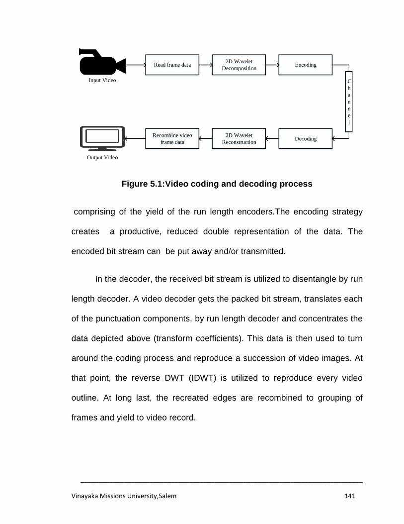
______________________________________________________________________________
Vinayaka Missions University,Salem 141
Input Video
Read frame data2D Wavelet
DecompositionEncoding
C
h
a
n
n
e
l
Recombine video
frame data
2D Wavelet
ReconstructionDecoding
Output Video
Figure 5.1:Video coding and decoding process
comprising of the yield of the run length encoders.The encoding strategy
creates a productive, reduced double representation of the data. The
encoded bit stream can be put away and/or transmitted.
In the decoder, the received bit stream is utilized to disentangle by run
length decoder. A video decoder gets the packed bit stream, translates each
of the punctuation components, by run length decoder and concentrates the
data depicted above (transform coefficients). This data is then used to turn
around the coding process and reproduce a succession of video images. At
that point, the reverse DWT (IDWT) is utilized to reproduce every video
outline. At long last, the recreated edges are recombined to grouping of
frames and yield to video record.
______________________________________________________________________________
Vinayaka Missions University,Salem 142
The video is spoken to as an arrangement of edges and every edge is
dealt with as a two-dimensional array of pixels (pels). The colour of every
pelcomprises of three segments. Discrete Wavelet Transform is done by
disintegrating the image into four sub groups (LL, LH, HL and HH) use
distinct wavelet filters and basically sub groups examining the yield. HH
subband gives the points of interest of inclining, HL subband gives flat subtle
elements and the LH subband gives vertical points of interest. The following
coarser level of coefficients is acquired by decaying the low recurrence
Subband LL as indicated in Fig. 5.2.
Down-sampling and Up sampling are generally utilized as a part of
image presentation, compression, and dynamic transmission. Down
sampling is the lessening in spatial determination while keeping the same
two-dimensional (2D) representation. It is commonly used to diminish the
capacity and/or transmission necessities of images. Up sampling is the
growing of the spatial determination while keeping the 2D representation of
an image.
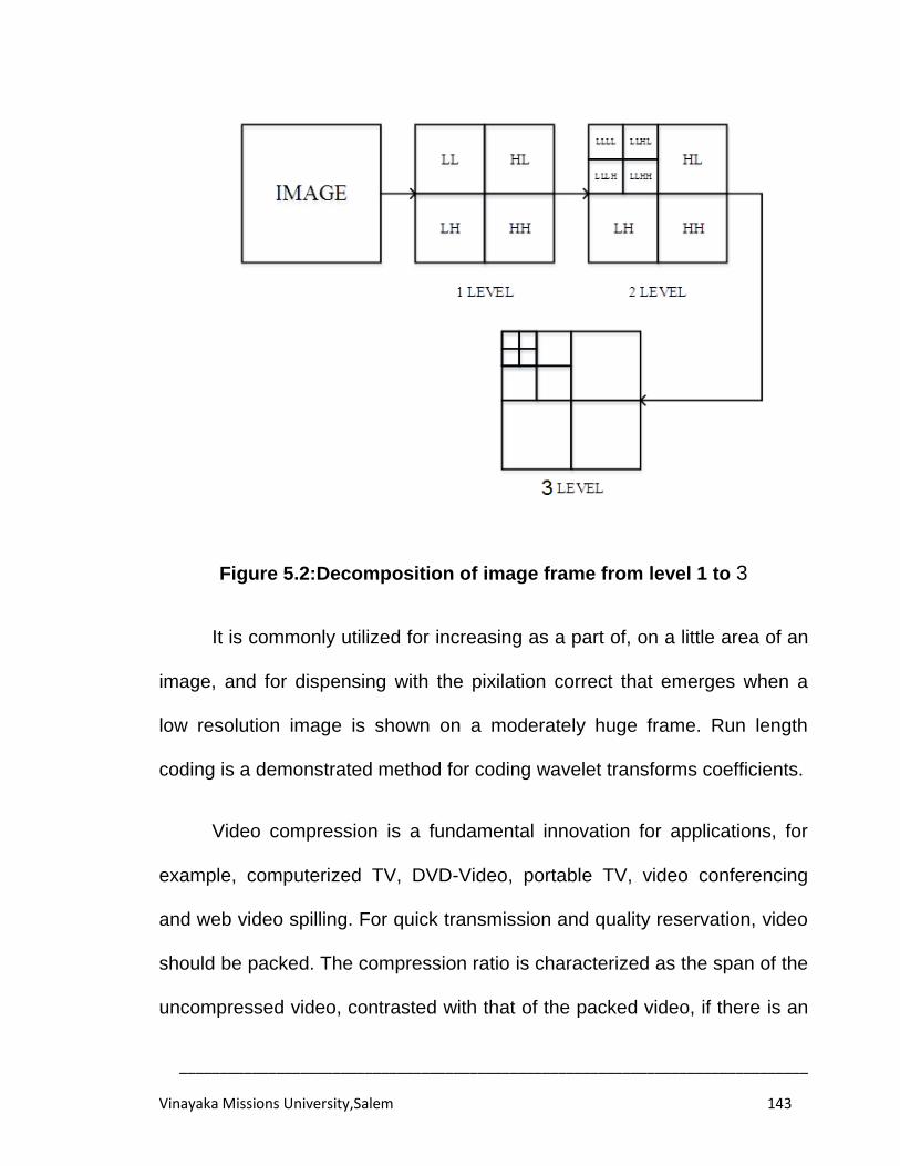
______________________________________________________________________________
Vinayaka Missions University,Salem 143
Figure 5.2:Decomposition of image frame from level 1 to 3
It is commonly utilized for increasing as a part of, on a little area of an
image, and for dispensing with the pixilation correct that emerges when a
low resolution image is shown on a moderately huge frame. Run length
coding is a demonstrated method for coding wavelet transforms coefficients.
Video compression is a fundamental innovation for applications, for
example, computerized TV, DVD-Video, portable TV, video conferencing
and web video spilling. For quick transmission and quality reservation, video
should be packed. The compression ratio is characterized as the span of the
uncompressed video, contrasted with that of the packed video, if there is an
______________________________________________________________________________
Vinayaka Missions University,Salem 144
occurrence of lossy video Codec. There are such a large number of written
works on the distinctive hardware usage of the DWT and those literary
works gave careful consideration to the accuracy of the DWT reckoning.
5.2 PROPOSED WAVELET BASED VIDEO COMPRESSION
In the course of the last couple of years there has been an incredible
increment in the utilization of video in computerized frame because of the
fame of the Internet. One can see video fragments in website pages, have
DVDs to stockpile video and HDTV will utilize a video group for telecast. To
comprehend the video groups, it is required to recognize the qualities of the
video and how they are utilized as a part of describing the configuration.
Video is a sequence of images which are shown all together. Each of
these images is known as a frame. We can't see little transforms in the
frames like a slight contrast of colour so video compression models don't
encode every one of the points of interest in the video, a percentage of the
subtle elements are lost. This is called lossy compression. It is conceivable
to get high compression ratios when lossy compression is utilized.
Commonly 30 frames are shown on the screen consistently. There will be
heaps of data rehashed in the back to back frames. For example, in the
episode that a tree is shown for one second, then 30 frames contain in it.
This data can be exploited as a part of the compression and the frames can
______________________________________________________________________________
Vinayaka Missions University,Salem 145
be characterized taking into account past edges. So back to back edges can
have data like move this some piece of the tree to this location. Frames can
be compacted utilizing just the data as a part of that frame (intraframe) or
utilizing data as a part of different edges too (interframe). Intraframe coding
permits irregular access operations like quick forward and gives adaptation
to non-critical failure. On the off chance that a piece of an edge is missing,
the following intraframe and the frames after that can be shown in light of the
fact that they just trust upon the intraframe.
Each colour can be pronounced to as a blend of red, green and blue.
Images can likewise be pronounced to utilizing this colour space. However
this colour space called RGB is not suitable, for compression since, it
doesn't consider the view of people. In YUV colour space where Y gives the
grayscale image. Human eye is more delicate to transforms of Y and this is
utilized as a part of compression. YUV is additionally utilized by the NTSC,
PAL, SECAM composite colour TV benchmarks.
Compression ratio is the ratio of the span of the first video to the
extent of the compacted video. To improve compression ratios pixels are
anticipated in view of different pixels. In spatial forecast of a pixel can be
acquired from pixels of the same image, in transient expectation, the
forecast of a pixel is obtained from a formerly transmitted image. Half breed
______________________________________________________________________________
Vinayaka Missions University,Salem 146
coding comprise if a forecast in the transient measurement with a suitable
decorrelation method in the spatial area. Movement remuneration builds up
a correspondence between components of adjacent images in the video
grouping. The fundamental use of movement compensation is giving a
valuable forecast to a given image from a reference image.
DCT (Discrete Cosine Transform) is utilized as a part of the greater
part of the institutionalized video coding algorithms. DCT is regularly done
on each 8x8 piece. 1D DCT requires 64 augmentations and for an 8x8 piece
8 1D DCTs are required. 2D DCT requires 54 increases and 468
augmentations and movements. 2D DCT is utilized as a part of MPEG, there
is additionally equipment accessible to do DCT. At the point when DCT is
performed, the upper left corner has the most noteworthy coefficients and
base right has the least, this makes compression less demanding. The
coefficients are numbered in a crisscross request from the upper left to base
right with the objective that there will be numerous little coefficients toward
the end. The DCT coefficients are then partitioned by the whole number
quantization worth to diminish exactness. After this division, it is conceivable
to free the lower coefficients, on the off chance that they are much littler than
the quantization. The coefficients are reproduced by the quantization esteem
before IDCT (Inverse DCT).
______________________________________________________________________________
Vinayaka Missions University,Salem 147
Wavelet transform systems have been researched for low bit rate
coding. Wavelet-based coding has preferable implementation over
conventional DCT-based coding. Much lower bit-rate and sensible
implementation are accounted for in view of the utilization of these
procedures to still images. A blend of wavelet transform and vector
quantization gives better implementation. Wavelet transform disintegrates
the image into a multifrequency filter representation, every segment of which
has its own particular recurrence qualities and spatial introduction highlights
that can be effectively utilized for coding. Wavelet-based coding has two
primary favorable circumstances: it is exceptionally adaptable and a
completely inserted bit stream may be effortlessly produced. The primary
favorable position over standard strategies, for example, MPEG is that video
development is accomplished in a completely installed style. Encoding and
transforming procedure can stop at a pre-decided bit rate. The encoded
stream can be scaled to deliver the imaginary spatial determination and
frame rate and in addition the obliged bit rate. Vector Quantization makes
utilization of the relationship and the excercise between adjacent pixels or
between recurrence groups. Wavelet transform with vector quantization
misuses the lingering relationship among diverse layers, if the wavelet
transform area utilizing square revision to enhance the coding productivity.
Further enhancements can likewise be made by adding to the versatile edge
______________________________________________________________________________
Vinayaka Missions University,Salem 148
methods for grouping in light of the complexity affectability attributes of the
human visual framework. Joint coding of the WT with trellis coded
quantization as a joint source/filter coding is a region to be considered.
Extra video coding exploration applying the wavelet transform on a
low bit rate correspondence filter is performed.Since the wavelet transform
creates different recurrence groups, multi recurrence movement estimation
is accessible for the transformed edge. It likewise gives a representation of
the worldwide movement structure. Likewise, the movement vectors in
lower-recurrence groups are anticipated with the more particular points of
interest of higher-recurrence groups. This progressive movement estimation
can likewise be executed with the division procedure that uses edge limits
from the zero-intersection focuses in the wavelet transform area. Every
recurrence band can be delegated worldly movement macro blocks or no-
transient action macro blocks. The most minimal band may be coded
utilizing a H.261 like coder which utilizes DCT, and alternate groups may be
coded utilizing vector quantization or trellis coded quantization.
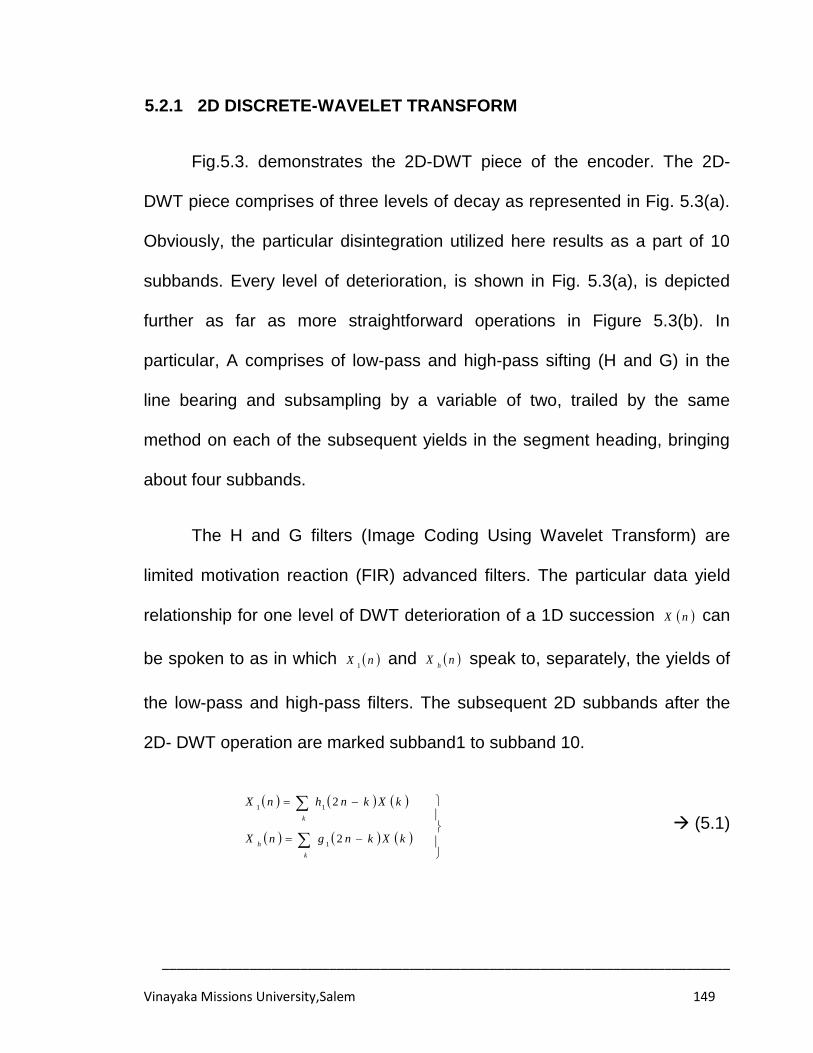
______________________________________________________________________________
Vinayaka Missions University,Salem 149
5.2.1 2D DISCRETE-WAVELET TRANSFORM
Fig.5.3. demonstrates the 2D-DWT piece of the encoder. The 2D-
DWT piece comprises of three levels of decay as represented in Fig. 5.3(a).
Obviously, the particular disintegration utilized here results as a part of 10
subbands. Every level of deterioration, is shown in Fig. 5.3(a), is depicted
further as far as more straightforward operations in Figure 5.3(b). In
particular, A comprises of low-pass and high-pass sifting (H and G) in the
line bearing and subsampling by a variable of two, trailed by the same
method on each of the subsequent yields in the segment heading, bringing
about four subbands.
The H and G filters (Image Coding Using Wavelet Transform) are
limited motivation reaction (FIR) advanced filters. The particular data yield
relationship for one level of DWT deterioration of a 1D succession nX can
be spoken to as in which nX1
and nXh
speak to, separately, the yields of
the low-pass and high-pass filters. The subsequent 2D subbands after the
2D- DWT operation are marked subband1 to subband 10.
k
h
k
kXkngnX
kXknhnX
2
2
1
11
(5.1)
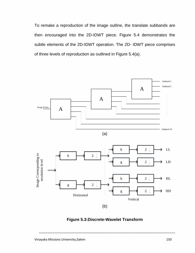
______________________________________________________________________________
Vinayaka Missions University,Salem 150
To remake a reproduction of the image outline, the translate subbands are
then encouraged into the 2D-IDWT piece. Figure 5.4 demonstrates the
subtle elements of the 2D-IDWT operation. The 2D- IDWT piece comprises
of three levels of reproduction as outlined in Figure 5.4(a).
A
A
A
Image Frame
Subband 1
Subband 2
Subband 10
(a)
h 2
g 2
h 2
g 2
h 2
g 2Imag
e C
orr
esp
on
din
g t
o
reso
luti
on
le
vel
Horizontal
Vertical
LL
LH
HL
HH
(b)
Figure 5.3:Discrete-Wavelet Transform
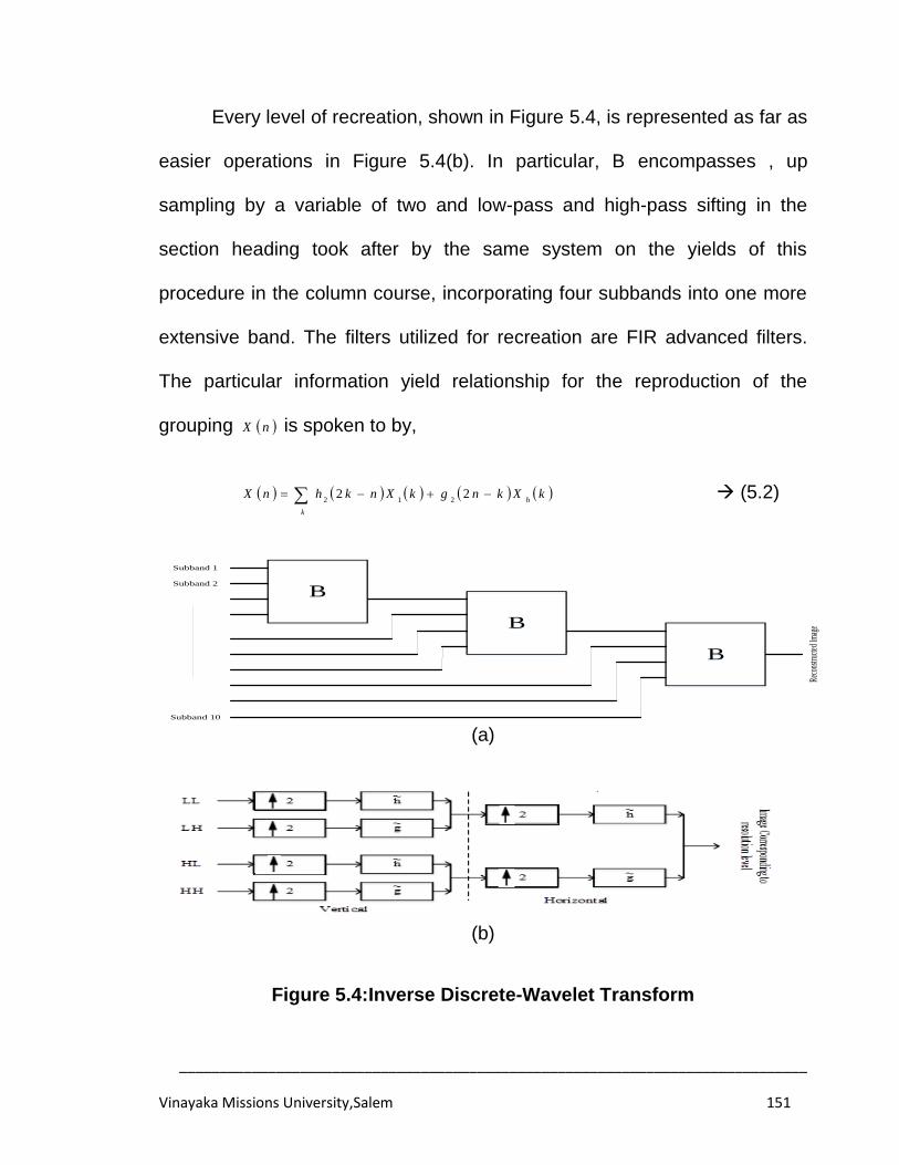
______________________________________________________________________________
Vinayaka Missions University,Salem 151
Every level of recreation, shown in Figure 5.4, is represented as far as
easier operations in Figure 5.4(b). In particular, B encompasses , up
sampling by a variable of two and low-pass and high-pass sifting in the
section heading took after by the same system on the yields of this
procedure in the column course, incorporating four subbands into one more
extensive band. The filters utilized for recreation are FIR advanced filters.
The particular information yield relationship for the reproduction of the
grouping nX is spoken to by,
k
hkXkngkXnkhnX 22
212 (5.2)
B
B
B
Reco
nstru
cted
Imag
e
Subband 1
Subband 2
Subband 10
(a)
(b)
Figure 5.4:Inverse Discrete-Wavelet Transform
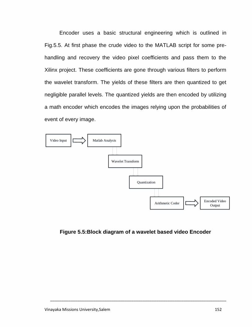
______________________________________________________________________________
Vinayaka Missions University,Salem 152
Encoder uses a basic structural engineering which is outlined in
Fig.5.5. At first phase the crude video to the MATLAB script for some pre-
handling and recovery the video pixel coefficients and pass them to the
Xilinx project. These coefficients are gone through various filters to perform
the wavelet transform. The yields of these filters are then quantized to get
negligible parallel levels. The quantized yields are then encoded by utilizing
a math encoder which encodes the images relying upon the probabilities of
event of every image.
Video Input Matlab Analysis
Wavelet Transform
Quantization
Arithmetic CoderEncoded Video
Output
Figure 5.5:Block diagram of a wavelet based video Encoder
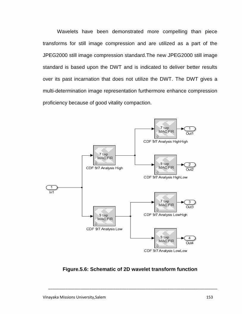
______________________________________________________________________________
Vinayaka Missions University,Salem 153
Wavelets have been demonstrated more compelling than piece
transforms for still image compression and are utilized as a part of the
JPEG2000 still image compression standard.The new JPEG2000 still image
standard is based upon the DWT and is indicated to deliver better results
over its past incarnation that does not utilize the DWT. The DWT gives a
multi-determination image representation furthermore enhance compression
proficiency because of good vitality compaction.
Figure.5.6: Schematic of 2D wavelet transform function
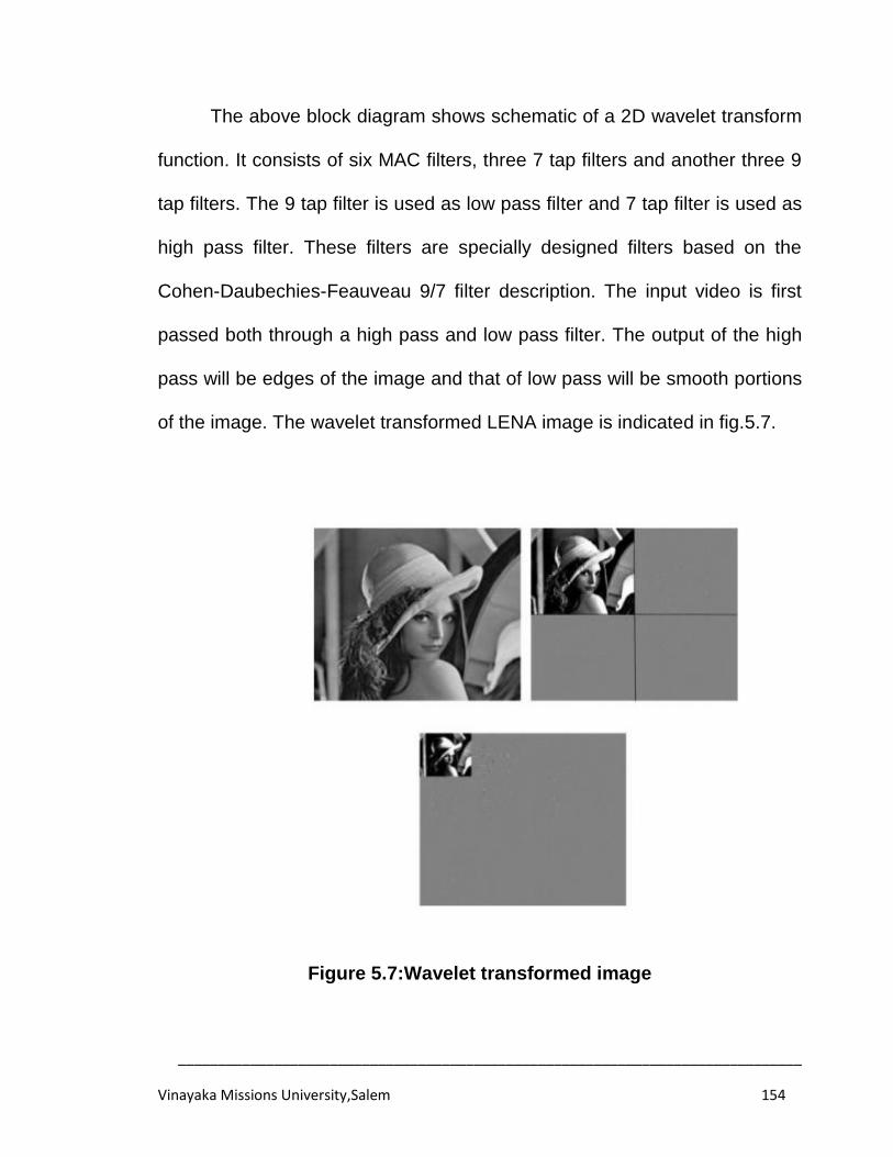
______________________________________________________________________________
Vinayaka Missions University,Salem 154
The above block diagram shows schematic of a 2D wavelet transform
function. It consists of six MAC filters, three 7 tap filters and another three 9
tap filters. The 9 tap filter is used as low pass filter and 7 tap filter is used as
high pass filter. These filters are specially designed filters based on the
Cohen-Daubechies-Feauveau 9/7 filter description. The input video is first
passed both through a high pass and low pass filter. The output of the high
pass will be edges of the image and that of low pass will be smooth portions
of the image. The wavelet transformed LENA image is indicated in fig.5.7.
Figure 5.7:Wavelet transformed image
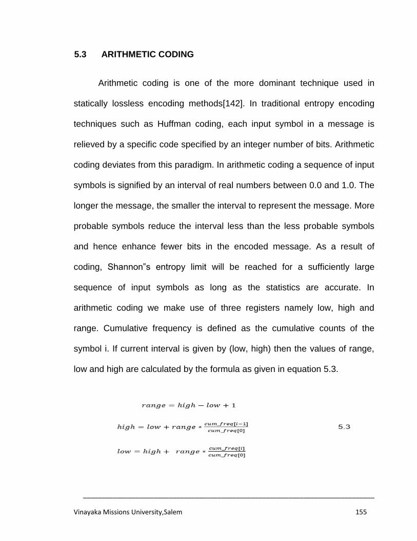
______________________________________________________________________________
Vinayaka Missions University,Salem 155
5.3 ARITHMETIC CODING
Arithmetic coding is one of the more dominant technique used in
statically lossless encoding methods[142]. In traditional entropy encoding
techniques such as Huffman coding, each input symbol in a message is
relieved by a specific code specified by an integer number of bits. Arithmetic
coding deviates from this paradigm. In arithmetic coding a sequence of input
symbols is signified by an interval of real numbers between 0.0 and 1.0. The
longer the message, the smaller the interval to represent the message. More
probable symbols reduce the interval less than the less probable symbols
and hence enhance fewer bits in the encoded message. As a result of
coding, Shannon‟s entropy limit will be reached for a sufficiently large
sequence of input symbols as long as the statistics are accurate. In
arithmetic coding we make use of three registers namely low, high and
range. Cumulative frequency is defined as the cumulative counts of the
symbol i. If current interval is given by (low, high) then the values of range,
low and high are calculated by the formula as given in equation 5.3.
______________________________________________________________________________
Vinayaka Missions University,Salem 156
Where,cum_freq[i] represents the cumulative frequency of the symbol „i‟. For
avoiding the underflowing of registers and to reduce the coding latency a
normalisation procedure is used which is as follows:
In this case a bit_to_follow counter is increased. Then if condition 1 is
satisfied then a „0‟ bit and bit_to_follows ones are written into output bit-
stream. If condition 2 is satisfied then a‟1‟bit and bit_to_follows zeros are
written into output bit-stream.
The arithmetic coder consists of three main parts, upper and lower
bound update, and common bit detector. For speedup, all valid bit-planes
are scanned in parallel. Significant wavelet coefficients are providing as
input to the arithmetic coder. Upper bound and lower bound update units in
arithmetic coder are used for updating the early intervals to 0 and 1.High
and low values are increased with cumulative probabilities and updated high
and low values are given as input to common bit detector unit. Output is then
passed to the code stream output unit in arithmetic coder. Cumulative
______________________________________________________________________________
Vinayaka Missions University,Salem 157
probability part will hold the frequency of happening of wavelet coefficient.
Upper bound and lower bound update units in arithmetic coder are realized
with carry look ahead adder and floating point multiplier.Certain practical
considerations must be taken into account in a practical realization of
arithmetic coding. These are the requirement to use finite precision
arithmetic, the need to ensure that underflows and overflows do not occur in
the arithmetic, and the need to ensure that the decoder terminates at the
correct point.This mechanism has the further advantage that it permits
encoding and decoding to be carried out in real time, whereas any
mechanism that required the entire message to be encoded before
transmission would produce significant delay.It is necessary to provide a
mechanism to signal to the decoder when the message is complete, so as to
circumvent the decoder appending random symbols to the message.
Number juggling coding is a type of entropy encoding utilized as a part
of lossless information compression. Ordinarily, a series of characters, for
example, the word hi is spoken to utilizing a settled number of bits per
character, as in the ASCII code. At the point when a string is transformed
over to number juggling encoding, oftentimes utilized characters will be put
away with less bits and not all that much of the time happening characters
will be put away with more bits, bringing about less bits utilized as a part of
aggregate. Number-crunching coding varies from different types of entropy
______________________________________________________________________________
Vinayaka Missions University,Salem 158
encoding, for example, Huffman coding in that instead of isolating the
information into part images and supplanting each with a code, math coding
encodes the whole message into a solitary number, a portion n where (0.0
≤n<1.0). The bit stream sentence structure is truly not the same as the
traditional MPEG linguistic structure.
5.4 IMPLEMENTATION RESULTS AND DISCUSSION
The proposed framework for the video compression utilizing wavelet
transform is examined as a part of the above segment and the framework
implementation is depicted in this segment. The proposed framework is
planned and examined utilizing Matlab programming and the relating VHDL
code is created. The created VHDL code is further amalgamation utilizing
Xilinx. Along these lines the framework is executed in two stage at first the
product recreation and examination by utilizing Matlab and for make this
proposed framework to peruse time application is transformed over to the
equipment portrayal dialect by utilizing the MATLAB HDL coder. At that point
the transformed over hardware code is blended utilizing Xilinx ISE. The
proposed procedure was broken down by utilizing math coding, the subtle
element clarification on this system is given beneath. A compression of 4:1
is reached in this architecture so the memory occupied by Codeword is
compact by four times when compared to the input with a bit rate of 8bpp.
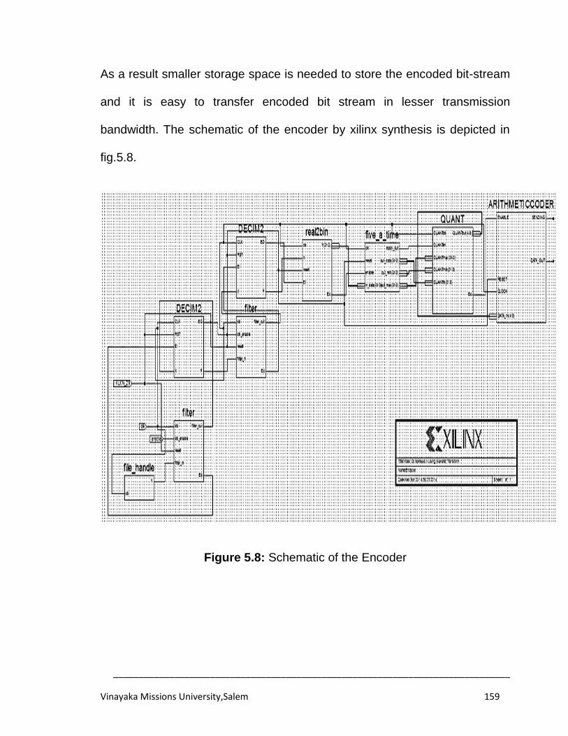
______________________________________________________________________________
Vinayaka Missions University,Salem 159
As a result smaller storage space is needed to store the encoded bit-stream
and it is easy to transfer encoded bit stream in lesser transmission
bandwidth. The schematic of the encoder by xilinx synthesis is depicted in
fig.5.8.
Figure 5.8: Schematic of the Encoder
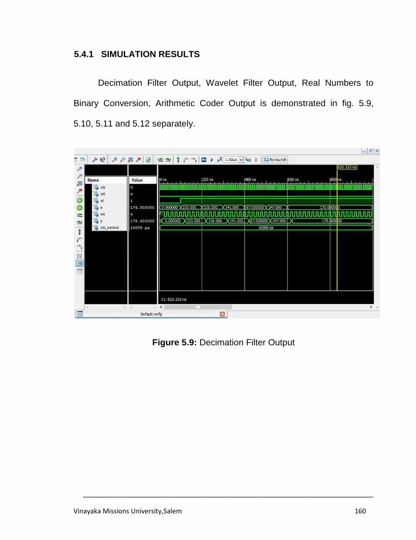
______________________________________________________________________________
Vinayaka Missions University,Salem 160
5.4.1 SIMULATION RESULTS
Decimation Filter Output, Wavelet Filter Output, Real Numbers to
Binary Conversion, Arithmetic Coder Output is demonstrated in fig. 5.9,
5.10, 5.11 and 5.12 separately.
Figure 5.9: Decimation Filter Output
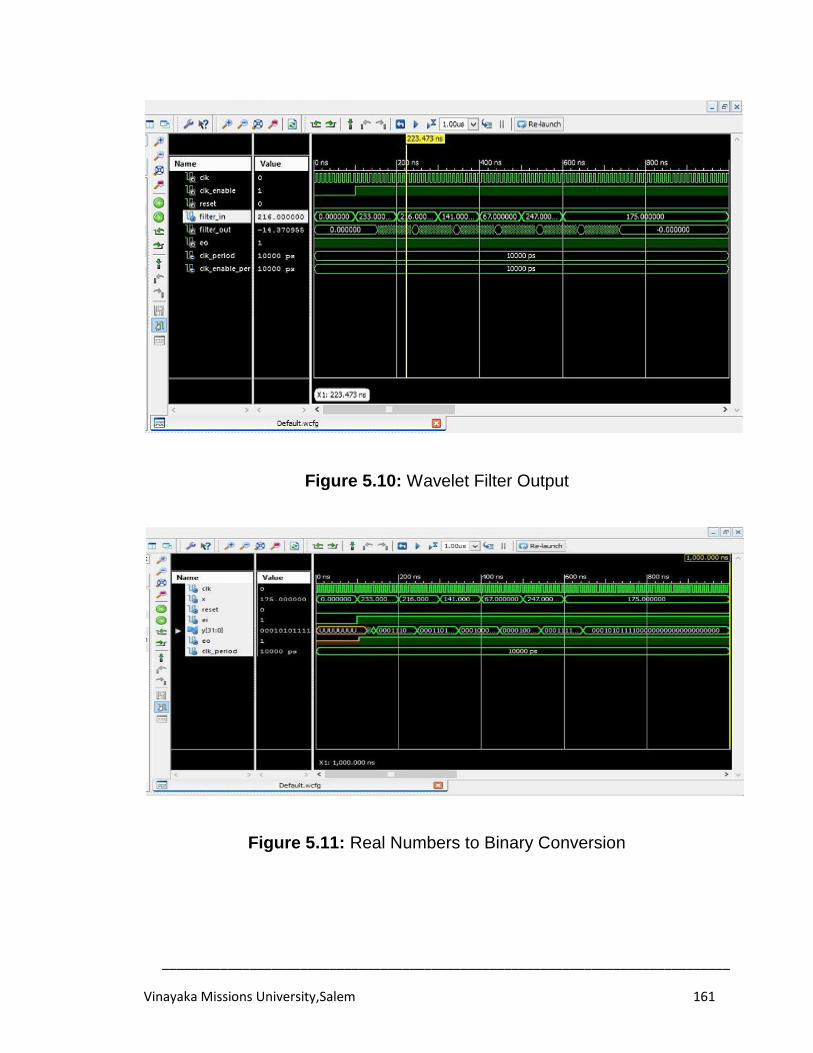
______________________________________________________________________________
Vinayaka Missions University,Salem 161
Figure 5.10: Wavelet Filter Output
Figure 5.11: Real Numbers to Binary Conversion
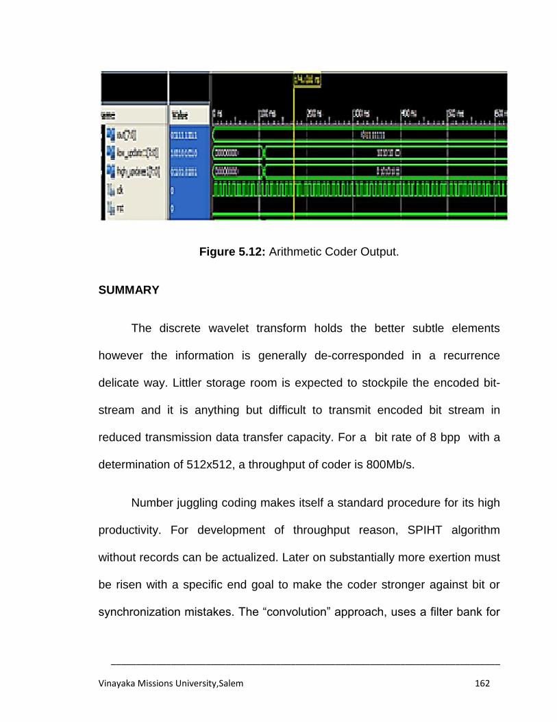
______________________________________________________________________________
Vinayaka Missions University,Salem 162
Figure 5.12: Arithmetic Coder Output.
SUMMARY
The discrete wavelet transform holds the better subtle elements
however the information is generally de-corresponded in a recurrence
delicate way. Littler storage room is expected to stockpile the encoded bit-
stream and it is anything but difficult to transmit encoded bit stream in
reduced transmission data transfer capacity. For a bit rate of 8 bpp with a
determination of 512x512, a throughput of coder is 800Mb/s.
Number juggling coding makes itself a standard procedure for its high
productivity. For development of throughput reason, SPIHT algorithm
without records can be actualized. Later on substantially more exertion must
be risen with a specific end goal to make the coder stronger against bit or
synchronization mistakes. The “convolution” approach, uses a filter bank for
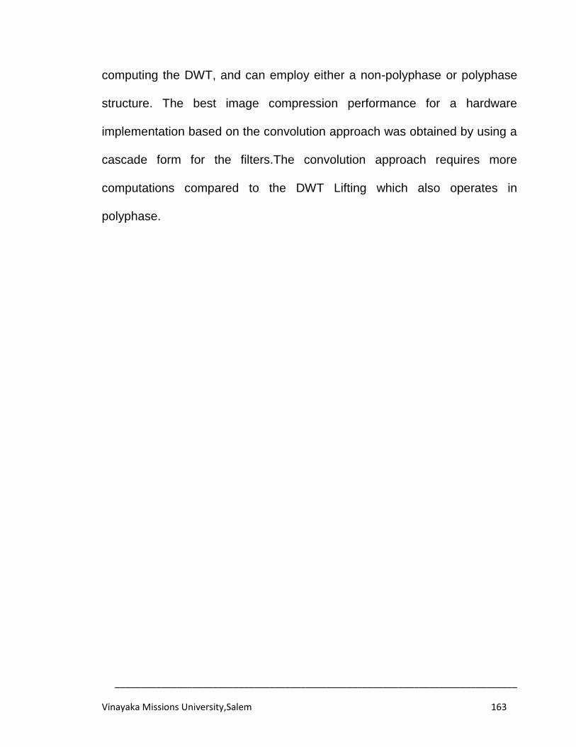
______________________________________________________________________________
Vinayaka Missions University,Salem 163
computing the DWT, and can employ either a non-polyphase or polyphase
structure. The best image compression performance for a hardware
implementation based on the convolution approach was obtained by using a
cascade form for the filters.The convolution approach requires more
computations compared to the DWT Lifting which also operates in
polyphase.
______________________________________________________________________________
Vinayaka Missions University,Salem 164
CHAPTER 6
CONCLUSIONS AND SCOPE FOR FUTURE WORK
6.1 CONCLUSIONS: CONTRIBUTIONS
Since the Wavelet Transform has been fruitful in accomplishing better
image quality at high compression ratios than conventional JPEG image
compression, it is only appropriate to accept that wavelet video compression
systems to have the capacity to beat the square based DCT compression
routines for H.26X and MPEG-X. A few wavelet compression systems have
been focused toward video applications. Later approach utilizes the 2D
wavelet transform for intra-frame coding, and also utilizes the wavelet
transform in the middle of frames for inter-frame coding.
In this sense, this thesis is meant to add to a novel framework for the
constant video compression utilizing discrete wavelet transform procedure.
The point is achieved in three stages, in the first stage we proposed a novel
5/3 2D-image compression system and executed in FPGA. It is understood
that the proposed strategy obliged less hardware space and minimized
postponement. In second stage of this work, we used SPIHT algorithm with
DWT, which enhanced the vitality effectiveness on image compression
alongside high SNR, expands the rate and decreases the measure of the
required storage space. At last in the last phase of work, we have added to a
______________________________________________________________________________
Vinayaka Missions University,Salem 165
productive video compression procedure utilizing DWT, which is suitable for
constant application, henceforth it is confirmed utilizing FPGA execution.
6.1.1 5/3 2D-DWT BASED IMAGE COMPRESSION
A productive VLSI structural planning for lifting based 5/3 DWT was
created, which is suitable for ongoing image compression. The lifting plan
5/3 algorithm was utilized for executing 1D-DWT using structural model. The
2D-DWT lifting based construction modeling was outlined utilizing 1D-DWT
lifting architectures. The proposed construction modeling uses less
hardware of committed multipliers contrasted with existing architectures. The
proposed structural model is actualized on Virtex-IV FPGA and it is watched
that the parameters, for example, LUT's and postponements are productive.
6.1.2 SPIHT BASED IMAGE COMPRESSION WITH DWT
SPIHT is an invaluable method utilized in this work for compacting
information, along with DWT for the image compression. The proposed
strategy focused to minimize processing vitality by considering wavelet-
based transform algorithm EEWITA. The algorithm keeps the high SNR,
expands the rate and decreases the span of the required storage space.
______________________________________________________________________________
Vinayaka Missions University,Salem 166
6.1.3 DWT BASED VIDEO COMPRESSION
Added to an adaptable hardware building design for the DWT based
video encoder, the encoder is realized utilizing MATLAB and VHDL. The
VHDL model is mimicked utilizing the Xilinx XST and ISIM Simulator. DWT
centre is utilized as a part of conjunction with an extremely basic number
juggling coder for quick and effective realization to show the capacity of the
encoder in the region of video compression. This work concentrates on the
DWT utilizing 9/7 channel, which gives great compression quality; however
is especially difficult to execute with high effectiveness because of the
inconsistentchannel coefficients. The building design has been coded in
VHDL on Xilinx stage and the objective FPGA gadget utilized is Virtex-IV
Pro crew. This design is feasible for continuous handling of DWT algorithm
applications. The discrete wavelet transform holds the better points of
interest. However, the information is generally de-associated in arecurrence
delicate way. Smaller storage room is expected to store the encoded bit
stream and it is anything but difficult to transmit encoded bit stream in lesser
transmission data transfer capacity. For a pixel exactness of 8 bits with a
determination of 512 x 512 pixels, the throughput of coder is 800 Mb/s.
Number juggling coding makes itself a standard system for its high
effectiveness. For development of throughput reason, SPIHT algorithm
without records can be executed.
______________________________________________________________________________
Vinayaka Missions University,Salem 167
6.2 FUTURE DIRECTION
The focus of this thesis was on the filter structure and coefficient
quantization aspect of DWT implementation. Considerable amount of work
has been done in the hardware architecture aspect of 2D-DWT
implementation, and it continues to be a field for future research. In spite of
the fact that this work gives some encouraging systems to support the
general execution of video compression utilizing wavelet transform, there
are still numerous issues. Some of the areas for future work are:
1. Further improvements in hardware performance can be obtained by
addressing hardware architecture issues such as pipelining, placement and
routing and memory access.
2. A complete 2D-DWT implementation will need to address issues related
to memory access for reading and writing of DWT coefficients and
intermediate results. A good implementation will require few memory
accesses, and use fast internal cache memory for intermediate results.
3. Multiple levels of DWT computation present the problem of growing signal
bit widths. Starting with 8-bit image data, the input to each successive DWT
level will have wider bit widths, making it impractical to save all bits of
precision in memory till the final decomposition level. Intermediate DWT
coefficients will have to be truncated after every level, so that data read from
and written to memory will have fixed bit widths. For the lifting
______________________________________________________________________________
Vinayaka Missions University,Salem 168
implementation, where bit widths grow after every filter within a single lifting
stage, intermediate signals may have to be truncated within a level.
Truncation of DWT coefficients and other intermediate values during the
computation of the DWT further impacts PSNR performance, and presents
another interesting topic for further study.
.4. To further improve the reconstructed video quality, we would like to
consider integrating error concealment at the decoder side after most of the
missing low frequency coefficients have been recovered. The error
concealment techniques, can be applied, to wavelet coefficient in either low
frequency or high frequency subbands.
______________________________________________________________________________
Vinayaka Missions University,Salem 169
REFERENCES
[1]
[2]
V.K. Padmaja and B. Chandrasekhar, "Literature Review of Image Compression Algorithm", International Journal of Scientific and Engineering Research, 2012, Vol. 3, No. 6, pp. 1-6. Alessandro Polpetta, Paolo Banelli, “Design and Performance of Huf Sequences in Medical Ultrasound Coded Excitation”, IEEE Transaction Ultrasonics, Ferroelectrics and Frequency Control, 2012, Vol. 59, No. 4.
[3] X. Wu and N.D. Memon, "CALIC- A Context Based Adaptive Lossless Image Coding Scheme", IEEE Transactions on Communications, May 1996, Vol. 45, pp. 437-444.
[4] M. Weinberger, G. Seroussi and G. Sapiro, "The LOCO-I Lossless Image Compression Algorithm: Principles and Standardization into JPEG-LS", IEEE Transactions on Image Processing, August 2000, Vol. 9, pp. 1309-1324.
[5] A. Gersho and R.M. Gray, "Vector Quantisation and Signal Compression", Kluwer Academic Publishers, 1992.
[6] M. Barnsley and L. Hurd, "Fractal Image Compression", AK Peters Ltd, Wellesley, 1993.
[7] C.E. Shanon, "A Mathematical Theory of Communication", Bell System Technical Journal, 1948, Vol. 27, pp. 623-656.
[8] R. Pasco, "Source Coding Algorithms for Fast Data Compression", Ph.D. thesis, Standford University, 1976.
[9] J.J. Rissanen, "Generalized Kraft Inequality and Arithmetic Coding", IBM Journal of Research and Development, May 1976, Vol. 20, pp. 198-203.
[10] J.J. Rissanen and G.G. Langdon, "Arithmetic Coding", IBM Journal of Research and Development, March 1976, Vol. 23, pp. 149-162.
______________________________________________________________________________
Vinayaka Missions University,Salem 170
[11] T.C. Bell, J.G. Cleary and I.H. Witten, "Text Compression", Advanced Reference Series, Englewood Cliffs, Prentice Hall, 1990.
[12] M. Ghanbari, "Standard Codecs: Image Compression to Advanced Video Coding", Institution of Electrical Engineers (IEE) Telecommunications series, 2003, pp. 43-53.
[13] M. Adams and F. Kossentini, "Reversible Integer-to-Integer Wavelet Transforms for Image Compression: Performance Evaluation and Analysis", IEEE Transactions on Image Processing, June 2000, Vol. 9, pp. 1010-1024.
[14] Recommendation ITU-T BT.500-10, "Methodology for the Subjective Assessment of the Quality of Television Pictures",ITU-T 2000,pp.1-40.
[15] C. Valens. "A Really Friendly Guide to wavelets",.Cole publications,California;USA,1999.
[16] R Polikar,”The Wavelet Tutorial Part IV Multiresolution Analysis:The Discrete Wavelet Transform”,Lowa State University, 2001.
[17] D. Taubman and M. Marcellin,“JPEG2000 Image Compression Fundamentals, Standards and Practice”, Kluwer Academic Publishers, Norwell, MA, 2002.
[18]
[19]
T.Ramaprabha,Dr M.Mohamed Sathik, “A Comparative Study of Improved Region Selection Process in Image Compression using SPIHT and WDR”, International Journal of Latest Trends in Computing,2010, Vol.1, Issue 2,pp.86-90. Philip J. Sementilli, Au Bilgina, and James H. Kasnerc,” Wavelet TCQ: submission to JPEG-2000”,Part of the SPIE Conference on Applications of Digital Image Processing XXI , San Diego. California July 1998.
[20] Qutubuddin Saifee, Ankur Gupta and Nishant Singh, “JPEG2000: Wavelets In Image Compression”, EE678 wavelets application Assignment,2013.
______________________________________________________________________________
Vinayaka Missions University,Salem 171
[21] M. Antonini, M. Barlaud, P. Mathieu and I. Daubechies, "Image coding using wavelet transform", IEEE Transaction on Image Processing,1992, Vol. 1, No. 2, pp. 205-220.
[22] S. Rama Mohan and Archit Yajnik, "Gujarati numeral recognition using wavelets and neural network", In Proceedings of Indian International Conference on Artificial Intelligence, 2005, pp. 397-406.
[23] Archit Yajnik and S. Rama Mohan, "Identification of Gujarati characters using wavelets and neural networks", Artificial Intelligence and Soft Computing, ACTA Press, 2006, pp. 150-155.
[24] R. Srivastava Rao Kunte and R.D. Sudhakar Samuel, "Online character/script recognition system for Kannada and other Indian languages employing wavelet features", In Proceedings of the Indo–European Conference on Multilingual Communication Technologies, New Delhi, 2002, pp. 26-31.
[25] Nhat Nguyen and Peyman Milanfar, "A wavelet-based interpolation–restoration method for super resolution (wavelet super resolution)", Circuits Systems Signal Process, 2002, Vol. 19, No. 4, pp. 321-338.
[26] Alex P. Pentland, "Interpolation using wavelet basis", IEEE Transactions on Pattern Analysis, Intell, 1994, Vol. 16, No. 4, pp. 410-414.
[27] Archit Yajnik and S. Rama Mohan, "Approximation of a signal using discrete wavelets transform", International Journal of Artificial Intelligence, 2009, Vol. 2, pp. 95-105.
[28] Archit Yajnik, "Approximation of a digital signal using Estimate Wavelet Transform", In Proceedings of International Conference on Computational Science and Its Applications (ICCSA), IEEE CPS, 2011,pp.171-175.
[29] Archit Yajnik, "Comparative study of oversampling the lossy acoustic signal using estimate wavelet transform and cubic spline interpolation", In Proceedings of the World Congress on Engineering 2013, WCE 2013, London, UK, July 2013, Vol. I, pp. 80-84.
______________________________________________________________________________
Vinayaka Missions University,Salem 172
[30] Archit Yajnik, "Wavelet Analysis and Its Applications, an Introduction", Narosa Publishing House Pvt. Ltd., New Delhi, India, 2012.
[31] S. Mallat, “A Theory for Multiresolution Signal Decomposition: The Wavelet Representation”, IEEE Transaction on Pattern Analysis and Machine Intelligence,1989, Vol. 11, No. 7, pp. 674-693.
[32] Durgasowjanya, K. N. H. Srinivas and P. Venkata Ganapathi, “FPGA Implementation of efficient VLSI Architecture for fixed point 1D DWT using Lifting Scheme”, International Journal of VLSI Design and Communication Systems,2012, Vol. 3,pp.35-41.
[33] Nagabushanam M and Ramachandran S., “Fast implementation of Lifting Based 1D/2D/3D DWT-IDWT Architecture for Image Compression”, International journal of computer Applications,2012, Vol. 12, Issue 11, pp. 23-29.
[34] K. Andra, C. Chakrabarti and T. Acharya, “A VLSI Architecture for Lifting-Based Forward and Inverse Wavelet Transform”, IEEE Transaction on Signal Processing,2002, Vol. 50, No. 4, pp. 966-977.
[35] M. Chang, and S. Hauck, "Automated least-significant bit datapath optimization for FPGAs", In Proceedings of IEEE Symposium on Field-Programmable Custom Computing Machines (FCCM), 2004, pp. 59-67.
[36] A. Benkrid, D. Crookes and K. Benkrid, "Design and implementation of a generic 2D biorthogonal discrete wavelet transform on an FPGA", In Proceedings of IEEE Symposium on Field-Programmable Custom Computing Machines (FCCM), 2001, pp. 190-198.
[37] K. Yamuna, C. Chandrasekhar,‟‟ Design and Implementation Of Efficient Lifting Based Dwt Architecture Using Wallace Tree Multiplier For Compression‟‟, International Journal of Engineering Research and Applications (IJERA), 2013, Vol. 3 ,pp. 1772-1777. .
[38] P.Rajesh, S.Srikanth, V.Muralidharan, “ An Efficient Architecture for Multi-Level Lifting 2-D DWT”, International Journal of Engineering Science and Innovative Technology , 2012, Vol.1, pp. 74-79.
______________________________________________________________________________
Vinayaka Missions University,Salem 173
[39] Rekha, K. B. Shivakumar, M. Z. Kurian, “Precision-Aware and quantization of Lifting Based DWT Hardware Architecture”, International Journal of Computer & Organization Trends, 2013, Vol.3, pp.262-268.
[40] C.J Lian, K.F. Chen, H.H. Chen, and L.G. Chen, “Lifting Based Discrete Wavelet Transform Architecture for JPEG2000”, IEEE International Symposium on Circuits and Systems, Sydney,Australia, 2001,Vol.2,pp.445-448.
[41] C.C. Liu,Y.H. Shiau, and J.M. Jou, “Design and Implementation of a Progressive Image Coding Chip Based on the Lifted Wavelet Transform” In Proceedings of the 11th VLSI Design/CAD Symposium, Taiwan, 2000.
[42] H. Liao, M.K. Mandal, and B.F. Cockburn, “Novel Architectures for Lifting-Based DWT” Electronics Letters,2002, vol. 38, no. 18,pp.1010–1012.
[43] J. M. Shapiro,” Embedded image coding using zerotree of wavelets coefficients”, IEEE Transactions on Signal Processing,1993,Vol. 41,no 12,pp. 3445-3462.
[44] Kim B.J., Pearlman W.A.,” An Embedded Wavelet Video Coder Using Three Dimensional Set Partitioning in Hierarchical Trees (3D-SPIHT)”,In Proceedings of Data Compression Conference 1997, Snowbird, USA, 1997, pp.251-260.
[45] Karlekar J., and Desai U, “SPIHT video coder”, TENCON ‟98: IEEE Region 10 International Conference on Global Connectivity in Energy, Computer, Communication and Control,1998, Vol. 1, pp. 45-58.
[46] B-J. Kim, Z. Xiong and W.A. Pearlman, " Low Bit Rate Scalable Video Coding With 3D Set Partitioning in Hierarchical Trees (3D SPIHT)", IEEE Transactions on Circuits and Systems for video technology,December 2000, Vol. 10, pp.1374-1387.
[47] H. Danyali and A. Mertins,“Fully spatial and snr scalable, SPIHT based image coding for transmission over heterogeneous networks”, Journal of Telecommunications and Information Technology, 2003,Vol. 2, pp. 92–98,
______________________________________________________________________________
Vinayaka Missions University,Salem 174
[48] E. Khan and M. Ghanbari , „‟ Wavelet based efficient color image coding technique‟‟, In Proceedings of image processing International Conference 02/2002,Vol.3,pp.241-244.
[49] Xun Guo; Yan Lu; Feng Wu; Wen Gao; Shipeng Li, „‟ Distributed multi-view video coding „‟ In Proceedings of Visual Communications and Image Processing 2006,Vol.6077.
[50] Anhong,Yao Zhao and Jeng-Shyang, „‟Pan Efficient Scalable Distributed Video Coding Based on Residual SW-SPIHT‟‟, In Proceedings of the 2008 Eighth International Conference on Intelligent Systems Design and Applications,2008, Vol. 3,pp. 594-597.
[51] M. Martina, and G. Masera, "Multiplierless, folded 9/7 - 5/3 wavelet VLSI architecture", IEEE Transactions on Circuits and Systems II, 2007, Vol. 54, No. 9, pp. 770-774.
[52] Li Wern Chew, Li-Minn Ang, and Kah Phooi Seng, “New Virtual SPIHT Tree Structures for Very Low Memory Strip-Based Image Compression”, IEEE Signal Processing Letters, Vol. 15, 2008, pp.389-392.
[53] Shang-Hsiu Tseng and Aldo Morales, " A 3D SPIHT Low Memory Encoding Approach for Video Compression", Digest of Technical Papers International Conference on Consumer Electronics, 2009, pp. 1-2.
[54] A. Burg, M. Wenk, M. Zellweger, M. Wegmueller, N. Felber, and W. Fichtner, “VLSI implementation of the sphere decoding algorithm”, In Proceedings of solid state circuits conference ESSCIRC-2004, Leuven, Belgium, Sept. 2004, pp. 303–306.
[55] Andrea.M,C.Erdem,B.Sankur,„‟Performance measures for video object segmentation and tracking‟‟,Journal IEEE Transactions on Image Processing, july2004, Vol 13,issue 7,pp 937-951.
[56] Y. Vatis, B. Edler, D. T. Nguyen and J. Ostermann, ”Motion- and Aliasing-compensated Prediction using a two-dimensional non-separable Adaptive Wiener Interpolation Filter”, IEEE international conference onimage processing,Egypt, 2009.Vol.19,pp.174-192.
______________________________________________________________________________
Vinayaka Missions University,Salem 175
[57] IlHong shin,Hyun Wook Park,‟‟ Adaptive up-sampling method using DCT for spatial scalability of scalable video coding‟‟,IEEE Transactions on Circuits and Systems for Video Technology February 2009,Vol. 19, Issue 2, ,pp 206-214.
[58] Eric J. Balster, Benjamin T. Fortener and William F. Turri, "Integer Computation of Lossy JPEG2000 Compression", IEEE Transactions on Image Processing, 2011, Vol. 20, No. 8, pp. 2386-2391.
[59] Jie-Bin Xu, Lai-Man Po and Chok-Kwan Cheung, “A New Prediction
Model Search Algorithm for Fast Block Motion Estimation”,In proceedings of Image processing, Santa Barbara,1997,Vol.3,pp.610-613
[60] Chun-Ho Cheung and Lai-Man,”Novel Cross-Diamond-Hexagonal Search Algorithms for Fast Block Motion Estimation”, IEEE Transactions on Multimedia, 2005,Vol 7,No.1,pp.16-22.
[61] T. Wiegand, “Joint Draft 5: Scalable Video Coding,” ISO/IEC MPEG and ITU-T VCEG, Doc. JVT-R201, Bangkok, Thailand, Jan. 2006.
[62] Aroh barjatya, “Block matching algorithms for motion estimation”,Final project paper Digital Image Processing, Utah state university, spring 2004.
[63] Sarp Ertürk, “A New Perspective to Block Motion Estimation for Video compression: High-Frequency Component Matching,” IEEE Signal processing letters, 2007,Vol.14, No.2.
[64] Lucas Brocki, “Kohonen Self-Organizing Map for the Traveling Salesperson Problem”, Recent Advances in Machatronics, 2007, pp.116-119.
[65] Meiqing Wang, Rong Liu and Choi-Hong Lai, "Adaptive Partition and Hybrid Method in Fractal Video Compression", Computers and Mathematics with Application, 2006, Vol. 51, No. 11, pp. 1715-1726.
______________________________________________________________________________
Vinayaka Missions University,Salem 176
[66] Suphakant Phimoltares and Atchara Mahaweerawat, "Image Edge Detection Using Weight Interconnection in Self-Organizing Map," Conference on Knowledge and Smart Technologies(KST2009), Chonburi, Thailand, Jul. 2009,pp.37-42.
[67] Armando Manduca; Raja Muthupillai; P. J. Rossman "Image processing for magnetic-resonance elastography",In Proceedings SPIE 2710 Medical Imaging,1996.
[68] Chang-Hoon Son, Ji-Won Kim, Sung-Gun Song, Seong-Mo Park and Young-Min Kim,"Low complexity embedded compression algorithm for reduction of memory size and bandwidth requirements in the JPEG2000 encoder", IEEE Transactions on Consumer Electronics, 2010, Vol. 56, No. 4, pp. 2421-2429.
[69] Nikola Sprljan, Sonja Grgic, Mislav Grgic “Modified SPIHT algorithm
for Wavelet packet image coding”,Real time imaging special issue on multi -dimensional image processing ,2005,Vol.11,pp.378-388.
[70] Nader Karimi, Shadrokh Samavi and Shahram Shirani, "Lossless Compression of RNAi Fluorescence Images Using Regional Fluctuations of Pixels", IEEE Journal of Biomedical and Health Informatics, 2013, Vol. 17, No. 2, pp. 259-268.
[71] Francesc Aràndiga, Pep Mulet and Vicent Renau, "Lossless and near-
lossless image compression based on multi resolution analysis", Journal of Computational and Applied Mathematics, 2013, Vol. 242, pp. 70-81.
[72] Karthik Krishnan, Michael W. Marcellin,Ali Bilgin, and Mariappan S.
Nadar,“Efficient Transmission of Compressed Data for Remote Volume Visualization”, IEEE transactions on medical imaging, September 2006,Vol. 25, no. 9, pp.1189-1199.
[73] Charalampos Doukas and Ilias Maglogiannis, “Region of Interest Coding Techniques for Medical Image Compression”, IEEE engineering in medicine and biology magazine, September/October 2007,pp.29-35.
______________________________________________________________________________
Vinayaka Missions University,Salem 177
[74] Yumnam Kirani Singh “ISPIHT-Improved SPIHT “A simplified and efficient subband coding scheme”, International conference on Computing Theory and Applications, 2007, pp.468-474.
[75] Yin-hua Wu Longxu Jin and Ke Zhang “An Improved Fast SPIHT Image Compression Algorithm for Aerial Applications”, Journal of multimedia, December 2011,Vol. 6, No. 6.
[76] Xingsong Hou, Min Han, Chen Gong and Xueming Qian, "SAR complex image data compression based on quadtree and zerotree Coding in Discrete Wavelet Transform Domain: A Comparative Study", Neurocomputing, 2015, Vol. 148, pp. 561-568.
[77] Bing-Fei Wu and Chung-Fu Lin, "An efficient architecture for JPEG2000 coprocessor", IEEE Transactions on Consumer Electronics, 2004, Vol. 50, No. 4, pp. 1183-1189.
[78] Chenwei Deng, Weisi Lin and Jianfei Cai, "Content-based image compression for arbitrary-resolution display devices", IEEE Transactions on Multimedia, 2012, Vol. 14, No. 4, pp. 1127-1139.
[79] Zhijun Fang, Naixue Xiong, Laurence T. Yang, Xingming Sun and Yan Yang, "Interpolation-based direction-adaptive lifting DWT and modified SPIHT for image compression in multimedia communications", IEEE Systems Journal, 2011, Vol. 5, No. 4, pp. 584-593.
[80] Xingsong Hou, Jing Yang, Guifeng Jiang, and Xueming Qian, "Complex SAR image compression based on directional lifting wavelet transform with high clustering capability", IEEE Transactions on Geoscience and Remote Sensing, 2013, Vol. 51, No. 1, pp. 527-538.
[81] Chun-Lung Hsu, Yu-Sheng Huang, Ming-Da Chang and Hung-Yen Huang, "Design of an error-tolerance scheme for discrete wavelet transform in JPEG 2000 encoder", IEEE Transactions on Computers, 2011, Vol. 60, No. 5, pp. 628-638.
______________________________________________________________________________
Vinayaka Missions University,Salem 178
[82] P.W.M. Tsang, T.C. Poon and A.S.M. Jiao, "Embedding intensity image in grid-cross down-sampling (GCD) binary holograms based on block truncation coding", Optics Communications, 2013, Vol. 304, pp. 62-70.
[83] Sha Wang, Dong Zheng, Jiying Zhao, Wa James Tam, and Filippo Speranza, "An image quality evaluation method based on digital watermarking", IEEE Transactions on Circuits and Systems for Video Technology, 2007, Vol. 17, No. 1, pp. 98-105.
[84] Zhigang Gao, and Yuan F. Zheng, "Quality constrained compression using DWT-based image quality metric", IEEE Transactions on Circuits and Systems for Video Technology, 2008, Vol. 18, No. 7, pp. 910-922.
[85] Zhiqiang Lin, Michael W. Hoffman, Nathan Schemm, Walter D. Leon-Salas, and Sina Balkır “A CMOS image sensor for multi-level focal plane image decomposition", IEEE Transactions on Circuits and Systems I: Regular Papers, 2008, Vol. 55, No. 9, pp. 2561-2572.
[86] Chih-Hsien Hsia, Jing-Ming Guo and Jen-Shiun Chiang,‟‟ Improved Low-Complexity Algorithm for 2D Integer Lifting-Based Discrete Wavelet Transform Using Symmetric Mask-Based Scheme‟‟IEEE Transactions on Circuits and Systems for Video Technology .2009; Vol.19,pp.1202-1208.
[87] Yongseok Jin and Hyuk-Jae Lee, “A Block-Based Pass-Parallel SPIHT Algorithm” IEEE Transactions on circuit and system for video technology”, Vol.22, NO. 7, july 2012.
[88] Nick Kingsbury, „‟Complex Wavelets for Shift Invariant Analysis and Filtering of Signals‟‟, Applied and Computational Harmonic Analysis 1 2001,Vol.10,pp.234–253.
[89] Peng-Lang Shui, „‟ Image denoising algorithm via doubly local Wiener filtering with directional windows in wavelet domain‟‟,Signal Processing Letters, IEEE ,2001, Vol.12 , Issue: 10 , pp.681-684.
[90] Karen Lees, (2002) “Image Compression Using Wavelets”, Report of MS,May 2002.
______________________________________________________________________________
Vinayaka Missions University,Salem 179
[91] J.A. Saghri, A.G. Tescher, and J.T. Reagan, "Practical transform
coding of multispectral imagery", IEEE Signal Processing Magazine, Jan. 1995, Vol. 12, pp. 32-43.
[92] B. R. Epstein, R. Hingorani, J. M. Shapiro, and M. Czigler, "Multispectral KLT-wavelet data compression for land sat thematic mapper images", In Proceedings of IEEE Data Compression Conference on Snowbird, UT, Mar. 1992, pp. 200-208.
[93] M. W. Marcellin, M. J. Gormish, A. Bilgin, and M. P. Boliek, "Overview of JPEG2000", In Proceedings of IEEE Data Compression Conference, Jun. 2000, pp. 523-541.
[94] Evgeny Belyaev,Pavlo O. Molchanov,Alexey Vinel, „‟The Use of Automotive Radars in Video-Based Overtaking Assistance Applications‟‟ IEEE Transactions on Intelligent Transportation Systems 2013,Vol.14,issue.3,pp.1035-1042.
[95] Z.H. Guan, F.J. Huang and W.J. Guan, "Chaos-based image encryption algorithm", Physics Letters A, 2005, Vol. 346, pp. 153-157.
[96]
T.G. Gao and Z.Q. Chen, "A new image encryption algorithm based on hyper-chaos", Physics Letters A, 2008, Vol. 372, pp. 394-400.
[97] C. Fu, G.Y. Zhang, O. Bian, W.M. Lei and H.F. Ma, "A novel medical image protection scheme using a 3-dimensional chaotic system", Plos One, 2014, Vol. 9.
[98] H.J. Gao, Y.S. Zhang, S.Y. Liang and D.Q. Li, "A new chaotic algorithm for image encryption", Chaos Soliton Fract, 2006, Vol. 29, pp. 393-399.
[99] G.D. Ye, "Image scrambling encryption algorithm of pixel bit based on chaos map", Pattern. Recognition Letters, 2010, Vol. 31, pp. 347-354.
[100] B. Hennelly and J.T. Sheridan, "Optical image encryption by random shifting in fractional Fourier domains", Optical Letters, 2003, Vol. 28, pp. 269-271.
______________________________________________________________________________
Vinayaka Missions University,Salem 180
[101] N. Singh and A. Sinha, "Gyrator transform-based optical image encryption using chaos", Optical Letters, 2009, Vol. 47, pp. 539-546.
[102] G.H. Situ and J.J. Zhang, "Double random-phase encoding in the Fresnel domain", Optical Letters, 2004, Vol. 29, pp. 1584-1586.
[103] Z.J. Liu, H.F. Zhao and S.T. Liu, "A discrete fractional random transform", Optics Communications, 2005, Vol. 255, pp. 357-365.
[104] C. Ling, X. Wu and S. Sun, "A general efficient method for chaotic signal estimation", IEEE Transactions on Signal Processing, 1999, Vol. 47, pp. 1424-1428.
[105] X. Wu, H. Hu and B. Zhang, "Parameter estimation only from the symbolic sequences generated by chaos system", Chaos Soliton Fract, 2004, Vol. 22, pp. 359-366.
[106] C.Q. Li and K.T. Lo, "Optimal quantitative cryptanalysis of permutation-only multimedia ciphers against plaintext attacks", Signal Process, 2011, Vol. 91, pp. 949-954.
[107] C.Q. Li, Y.S. Liu, L.Y. Zhang and K.W. Wong, "Cryptanalyzing a class of image encryption schemes based on Chinese remainder theorem", Signal Process Image Communication, 2014, Vol. 29, pp. 914-920.
[108] Y.Frauel, A.Castro,T.Naughton and B.Javidi,"Security analysis of optical encryption",In Proceedings of SPIE,2005, Vol.5986, pp. 25-34.
[109] Y. Frauel, A. Castro, T. Naughton and B. Javidi, "Resistance of the double random phase encryption against various attacks", Optical Express, 2007, Vol. 15, pp. 10253-10265.
[110] J. Lang, R. Tao and Y. Wang, "Image encryption based on the multiple-parameter discrete fractional fourier transform and chaos function", Optics Communication, 2010, Vol. 283, pp. 2092-2096.
[111] L.S. Sui, K.K. Duan and J.L. Liang, "Double-image encryption based on discrete multiple-parameter fractional angular transform and two-coupled logistic maps", Optics Communication, 2015, Vol. 343, pp. 140-149.
______________________________________________________________________________
Vinayaka Missions University,Salem 181
[112]
[113]
M. Rabbani and P.W. Jones, "Digital Image 1991 compression Techniques", SPIE Press, Bellingham, Washington, USA,1991, Vol. 7. . Ms. Mansi Kambli and Ms. Shalini Bhatia, “Comparison of different Fingerprint Compression Techniques” Signal & Image Processing International Journal (SIPIJ), 2010, Vol. 1, N0. 1,pp.27-39.
[114] C. Chrysafis, "Wavelet Image Compression Rate Distortion Optimizations and Complexity Reductions", (Ph.D. thesis), Citeseer, 2000.
[115]
[116]
Usha Bhanu.N and Dr.Chilambuchelvan, „‟A Detailed Survey on VLSI Architectures for Lifting based DWT for efficient hardware implementation”,Inernational Journal of VLSI design and Communication systems(VLSICS),2012 ,Vol.3,No.2.pp.143-163. M. Vetterli, and J. Kova cevic, "Wavelets and subband coding", Prentice-Hall, Inc., Upper Saddle River, NJ, USA, 1995.
[117] M. Alam, C. Rahman, W. Badawy and G. Jullien, "Efficient distributed arithmetic based DWT architecture for multimedia applications", In Proceedings of International Work. SoC for Real Time Applications, 2003, pp. 333-336.
[118] P. Tseng, Y. Chang, Y. Huang, H. Fang, C. Huang and L. Chen, "Advances in Hardware Architectures for Image and Video Coding – A Survey",In Proceedings of IEEE, 2005, Vol. 93, No. 1, pp. 184-197.
[119] M. Adams, and F. Kossentini, "JasPer: a software-based JPEG-2000 codec implementation", In Proceedings of IEEE International Conference on Image Processing, 2000, Vol. 2, pp. 53-56.
[120] K. Kotteri, S. Barua, A. Bell, and J. Carletta, "A comparison of hardware implementations of the biorthogonal 9/7 DWT: convolution versus lifting", IEEE Transactions on Circuits and Systems II, 2005, Vol. 52, No. 5, pp. 256-260.
______________________________________________________________________________
Vinayaka Missions University,Salem 182
[121] Husain K. Bhaldar, V. K. Bairagi and R. B. Kakkeri, “Hardware Design of 2D High Speed DWT by Using Multiplierless 5/3 Wavelet Filters”, International Journal of Computer Applications,2012, Vol. 59, No. 17, pp. 42-46.
[122] Sowmya KB, Savita Sonali and M Nagabushanam, “Optimized DA Based DWT-IDWT for Image Compression”, International Journal of Electrical and Electronics Engineering, 2013, Vol. 1, Issue 1,pp.67-71.
[123] Naseer M. Basheer, Mustafa Mushtak Mohammed, “Design and FPGA Implementation of a Lifting Scheme of 2D-DWT Architecture”, International Journal of Recent Technology and Engineering, 2013, Vol. 2, Issue. 1, pp. 34-38.
[124] B.-F.Wu and C.F. Lin, “A high-performance and memory-efficient pipeline architecture for the 5/3 and 9/7 discrete wavelet transform of JPEG2000 codec”, IEEE Trans. on Circuit and Systems for Video Technology,2005, Vol. 15, pp. 1615-1628.
[125] S. Barua, J.E. Carletta, K.A. Kotteri and A.E. Bell, “ An efficient architecture for lifting based two-dimensional discrete wavelet transforms”, The VLSI Journal,2004,Vol. 38, pp.341-352.
[126]
[127] [128] [129]
W Zhang, Z Jiang, Z Gao, Y Liu, An efficient VLSI architecture for lifting-based discrete wavelet transform. IEEE Trans. Circuits System II,2012,Vol.59,pp.158–162. A Darji, S Agrawal, A Oza, V Sinha, A Verma, SN Merchant, A Chandorkar”, Dual-scan parallel flipping architecture for a lifting-based 2D discrete wavelet transform”, IEEE Transactions Circuits Systems.II, 2014.Vol.61,pp. 433–437. Xin Tian, Lin Wu, Yi-Hua Tan, and Ji-Wen Tian, “Efficient Multi-Input/ Multi-Output VLSI Architecture for Two-Dimensional lifting-Based Discrete Wavelet Transform”, IEEE Transaction On Computers, 2011, Vol. 60, No. 8,pp.1207-1211.
Milad Ghantous, Magdy Bayomi, “P2E-DWT: A Parallel and Pipelined Efficient Architecture of 2D Discrete Wavelet Transform”, IEEE international symposium on circuits and systems, 2011,pp.941-944.
______________________________________________________________________________
Vinayaka Missions University,Salem 183
[130] M. Antonini, M. Barland, P. Mathieu, and I. Daubechies, "Image coding using the wavelet transform", IEEE Transaction on Image Process, Apr. 1992, Vol. 1, No. 2, pp. 205-220.
[131] S. Grgic, M. Grgic, and B. Zovko-Cihlar, "Performance analysis of image compression using wavelets", IEEE Transaction Industrial Electronics, Jun. 2001, Vol. 48, No. 3, pp. 682-695.
[132] M. L. Hilton, B. O. Jawerth, and A. Sengupta, "Compressing still and moving images with wavelets", Multimedia System, 1994, Vol. 2, No. 5, pp. 218-227.
[133] F. S. Al-Kamali, M. I. Dessouky, B. M. Sallam, F. Shawki, and F. E. A. El-Samie, "Transceiver scheme for single-carrier frequency division multiple access implementing the wavelet transform and peak to-average-power ratio reduction methods",IET Communication, Jan. 2010, Vol. 4, No. 1, pp. 69-79.
[134] D. Taubman and M.W. Marcellin, "JPEG2000 Image Compression: Fundamentals, Standards and Practice", Boston MA: Academic publishers Kluwer, 2002.
[135] N. Chen, W. Wan, and H.-D. Xiao, "Robust audio hashing based on discrete-wavelet-transform and nonnegative matrix factorisation", IET Communication, Sep. 2010, Vol. 4, No. 14, pp. 1722-1731.
[136] A. Said and W.A. Pearlman, "A new, fast and efficient image codec based on set-partitioning in hierarchical trees", IEEE Transactions on Circuits Systems and Video Technology, Jun. 1996, Vol. 6, pp. 243-250.
[137]
[138]
[139]
T.W. Fry and S.A. Hauck, "SPIHT image compression on FPGAs", IEEE Transactions on Circuits Systems on Video Technology, Sep. 2005, Vol. 15, pp. 1138-1147. Mayank Nema, Lalita Gupta, N.R. Trivedi,”Video Compression Using SPIHT and SWT Wavelet”, International Journal of Electronics and Communication Engineering, 2012, Vol.5, pp.1-8. D. Taubman, "High performance scalable image compression with EBCOT", IEEE Trans. Image Processing, Jul. 2000, Vol. 9, pp. 1151- 1170.
______________________________________________________________________________
Vinayaka Missions University,Salem 184
[140]
S. Narasimhulu, Dr.T.Ramashri,”Gray-Scale Image Compression using DWT-SPIHT Algorithm”, International Journal of Engineering Research and Applications, 2012, Vol.2, pp.902-905.
[141] [142]
B Eshwar Reddy and K Venkata Narayana, “A Lossless Image Compression Using Traditional and Lifting Based Wavelets”, Signals and Image Processing: An International Journal, 2012,Vol.3, No.2,pp.213-222.
[141] Med Karim Abdmouleh, Atel Masmoudi, Med Salim Boouhlel,”A new method which combines Arithmetic Coding with RLE for lossless image compression”,Journal of Sofware Engineeringand Application,2012,Vol.5,pp.41-44.
______________________________________________________________________________
Vinayaka Missions University,Salem 185
LIST OF PUBLICATIONS
1. Shriram P Hegde and S Ramachandran, "FPGA Implementation of an
Efficient VLSI Architecture for Lift Based 5/3 DWT", IOSR Journal of VLSI and Signal Processing (IOSR-JVSP), 2014, Vol. 4, No. 5, pp. 18-23.
2. Shriram P Hegde and S. Ramachandran, "Implementation of DWT-SPIHT
Algorithm for Image Compression", Progress In Science and Engineering Research Journal, 2014, Vol. 02, No. 4, pp. 161-166.
3. Shriram P Hegde and S. Ramachandran, "Implementation of CDF 5/3 Wavelet Transform", International Journal of Electrical, Electronics and Data Communication, 2014, Vol. 2, No. 11, pp. 36-38.
4. Shriram P Hegde and S Ramachandran, "Implementation of Wavelet Based
Video Encoder", International Journal of Advanced Research in Science, Engineering and Technology, 2015, Vol. 2, No. 6, pp. 680-684.
Recommended