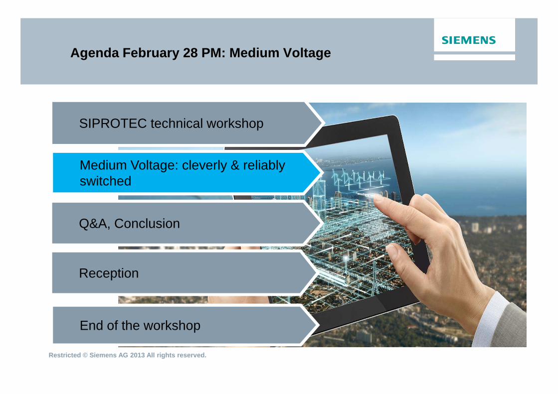
Agenda February 28 PM: Medium Voltage
SIPROTEC technical workshop
Medium Voltage: cleverly & reliably switched
Restricted © Siemens AG 2013 All rights reserved.
Q&A, Conclusion
Reception
End of the workshop
Highlights
Siemens’ world acclaimed expertise and technological know-how brought to your doorsteps
The Power Academy Lagos is part of an international network
The trainers undergo international train-the-trainer programs
The training portfolio covers every aspect of electrical conversion chain adapted to suit local requirements
The curriculum-based certification is locally and internationally accredited
World class facilities, Top class Training organization and special services
2
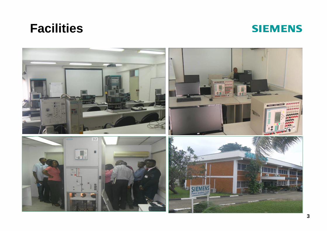
Facilities
3
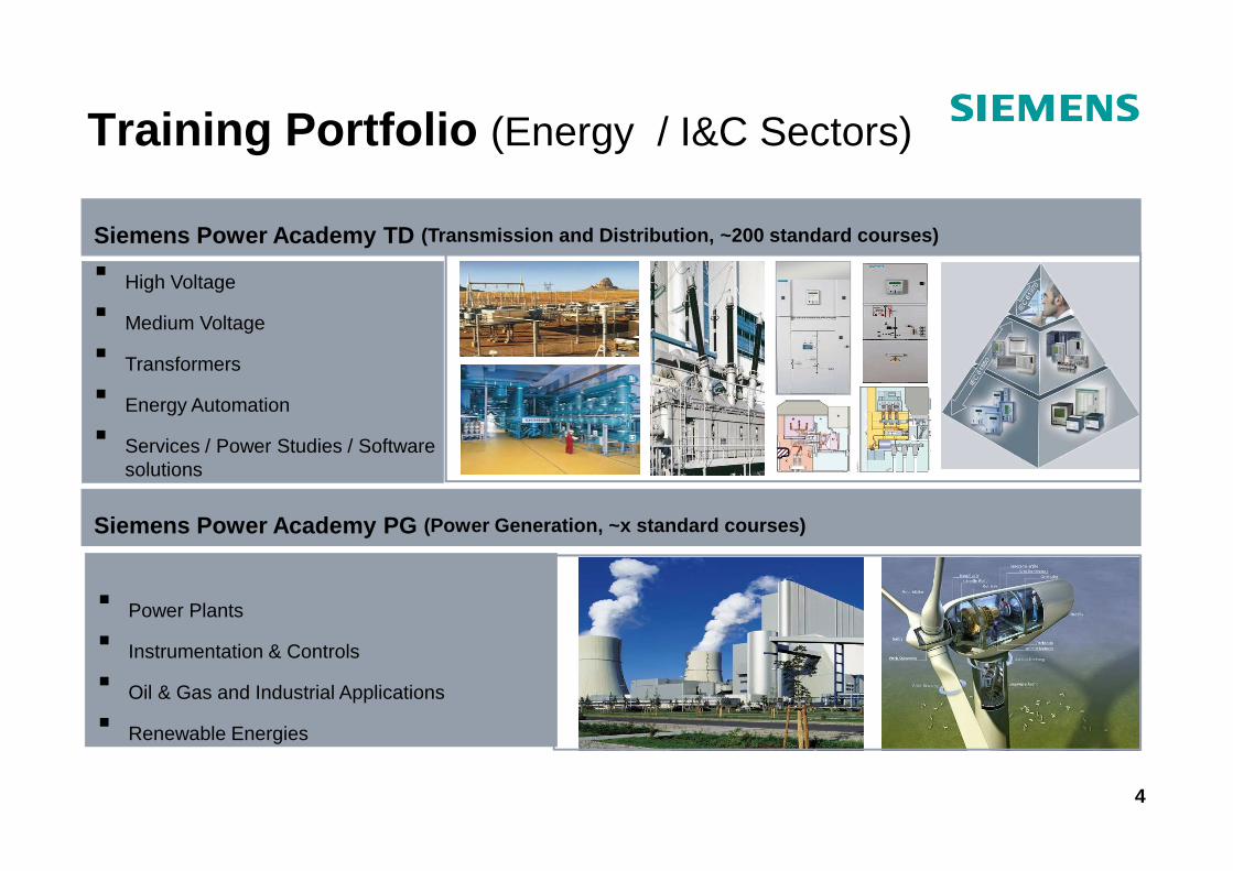
Training Portfolio (Energy / I&C Sectors)
� High Voltage
� Medium Voltage
� Transformers
� Energy Automation
� Services / Power Studies / Software
Siemens Power Academy TD (Transmission and Distribution, ~200 standard cours es)
� Services / Power Studies / Software solutions
� Power Plants
� Instrumentation & Controls
� Oil & Gas and Industrial Applications
� Renewable Energies
Siemens Power Academy PG (Power Generation, ~x standard courses)
4
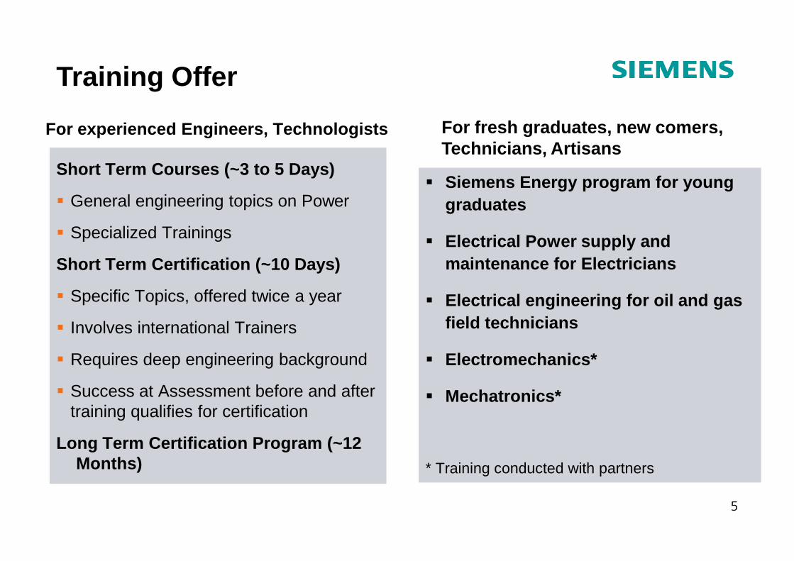
For experienced Engineers, Technologists
Short Term Courses (~3 to 5 Days)
� General engineering topics on Power
� Specialized Trainings
Short Term Certification (~10 Days)
� Siemens Energy program for young graduates
� Electrical Power supply and maintenance for Electricians
For fresh graduates, new comers,Technicians, Artisans
Training Offer
� Specific Topics, offered twice a year
� Involves international Trainers
� Requires deep engineering background
� Success at Assessment before and after training qualifies for certification
Long Term Certification Program (~12 Months)
� Electrical engineering for oil and gas field technicians
� Electromechanics*
� Mechatronics*
* Training conducted with partners
5
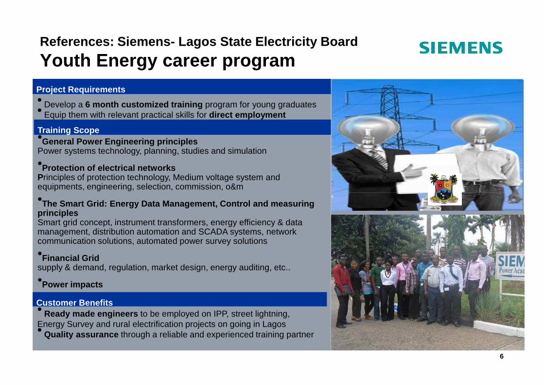
•General Power Engineering principlesPower systems technology, planning, studies and simulation
•Protection of electrical networksPrinciples of protection technology, Medium voltage system and equipments, engineering, selection, commission, o&m
•
References: Siemens- Lagos State Electricity Board
Youth Energy career programProject Requirements
Training Scope
• Develop a 6 month customized training program for young graduates • Equip them with relevant practical skills for direct employment
•The Smart Grid: Energy Data Management, Control and measuring principlesSmart grid concept, instrument transformers, energy efficiency & data management, distribution automation and SCADA systems, network communication solutions, automated power survey solutions
•Financial Gridsupply & demand, regulation, market design, energy auditing, etc..
•Power impacts
6
Customer Benefits• Ready made engineers to be employed on IPP, street lightning, Energy Survey and rural electrification projects on going in Lagos• Quality assurance through a reliable and experienced training partner
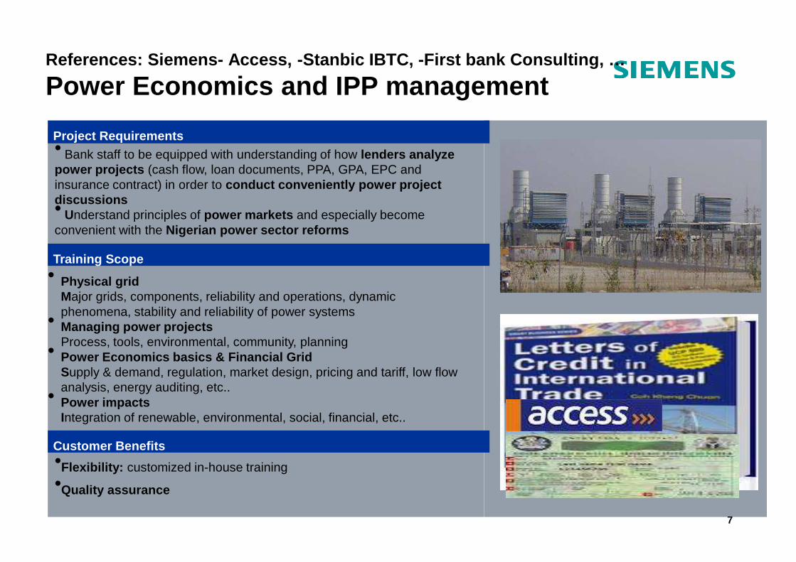
• Physical grid
References: Siemens- Access, -Stanbic IBTC, -First b ank Consulting, …
Power Economics and IPP management
Project Requirements
Training Scope
• Bank staff to be equipped with understanding of how lenders analyze power projects (cash flow, loan documents, PPA, GPA, EPC and insurance contract) in order to conduct conveniently power project discussions• Understand principles of power markets and especially become convenient with the Nigerian power sector reforms
• Physical gridMajor grids, components, reliability and operations, dynamic phenomena, stability and reliability of power systems• Managing power projectsProcess, tools, environmental, community, planning• Power Economics basics & Financial GridSupply & demand, regulation, market design, pricing and tariff, low flow analysis, energy auditing, etc..• Power impactsIntegration of renewable, environmental, social, financial, etc..
7
Customer Benefits•Flexibility: customized in-house training•Quality assurance
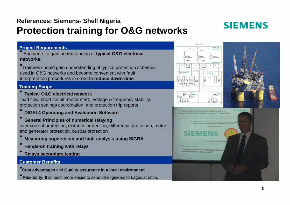
• Typical O&G electrical networkload flow, short circuit, motor start, voltage & frequency stability, protection settings coordination, and protection trip reports
References: Siemens- Shell Nigeria
Protection training for O&G networks
Project Requirements
Training Scope
• Engineers to gain understanding of typical O&G electrical networks .•Trainees should gain understanding of typical protection schemes used in O&G networks and become convenient with fault interpretation procedures in order to reduce down-time
protection settings coordination, and protection trip reports • DIGSI 4 Operating and Evaluation Software• General Principles of numerical relayingover current protection, distance protection, differential protection, motor and generator protection, busbar protection• Measuring supervision and fault analysis using SIGR A • Hands-on training with relays• Relays secondary testing
8
Customer Benefits•Cost advantages and Quality assurance in a local environment• Flexibility: I t is much more easier to send 36 engineers to Lagos at once.
Siemens Power Academy Lagos
Table of content
1. Introduction
2. Switching Devices, types and their selection
Copyright © Siemens AG 2008. All rights reserved.Copyright © Siemens Limited Nigeria 2013. All right s reserved. 9
3. Technical data of MV Switchgears
4. More Technical Information for MV Switchgears
5. Circuit Breakers – functions and types
Siemens Power Academy Lagos
6. Types of MV switchgears:
(i). MV Air-Insulated Switchgears (AIS);
(ii). MV Vacuum Switchgears;
Copyright © Siemens AG 2008. All rights reserved.Copyright © Siemens Limited Nigeria 2013. All right s reserved. 10
(iii). MV Gas-Insulated Switchgears (GIS).
7. Global MV Production Locations and Examples of Industrial applications.
1. Introduction:
According to international rules, there are only two voltage levels:
• Low-voltage: up to and including 1kV AC (or 1,500 V DC)
• High-voltage: above 1kV AC (or 1,500 V DC).
The term “medium-voltage” has come to be used for the voltages required for regional power distribution that are part of the high-voltage range from 1kV AC up to and including 52kV AC.
Most operating voltages in the medium-voltage systems are in the 3kV AC to 40.5 kV AC
11
Most operating voltages in the medium-voltage systems are in the 3kV AC to 40.5 kV AC range. The table in the next slide however shows the nomenclatures according to IEC.
High operating voltages (and therefore low currents) are preferred for power transmission in order to minimize losses.
In some countries, majority of medium-voltage systems in public power supplies are operated in the 10kV to 30kV range. In Nigeria, 11kV to 33kV.
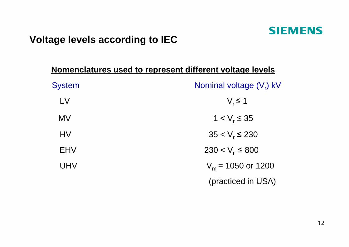
Voltage levels according to IEC
Nomenclatures used to represent different voltage l evels
System Nominal voltage (Vr) kV
LV Vr ≤ 1
MV 1 < Vr ≤ 35r
HV 35 < Vr ≤ 230
EHV 230 < Vr ≤ 800
UHV Vm = 1050 or 1200
(practiced in USA)
12
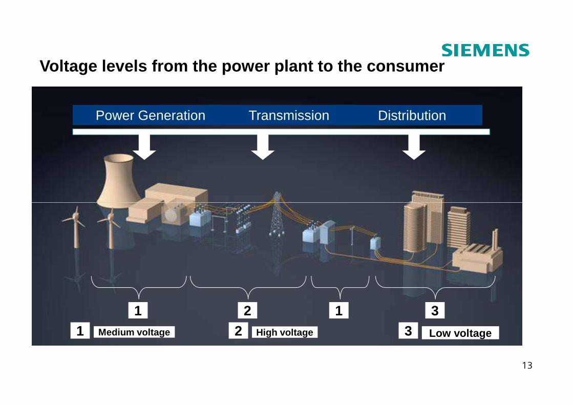
Voltage levels from the power plant to the consumer
DistributionTransmissionPower Generation
13
1 2 311 2 3Medium voltage High voltage Low voltage
2. Switching devices
What are switching devices?Switching devices are devices used to close (make) or open (break) electrical circuits. In other words, they are gears used for switching i.e. switchgears. The process of making and/or
14
switching i.e. switchgears. The process of making and/or breaking the electrical circuit may be associated with the stress of
• No-load switching;
• Breaking of operating currents;
• Breaking of short-circuit currents.
Types of Switching Devices and what they do:
Circuit breakers
Can make and break all currents within the scope of their ratings, from small inductive and capacitive load currents up to the full short-circuit current, and this under all fault conditions in the power supply system, such as earth faults, phase opposition, etc.
Switches
Can switch currents up to their rated normal current and make on existing short-circuits (up to their rated short-circuit making current).
15
(up to their rated short-circuit making current).
Disconnectors (Isolators)
May exclusively be switched on no-load. Cannot switch on and off load currents. Cannot switch off short-circuit currents. Their function is to “isolate” downstream devices so they can be worked on.
Switch-disconnectors (load-break switches)
The combination of a switch and a disconnector, or a switch with isolating distance.
Contactors
Load breaking devices with limited short-circuit making or breaking capacity. They are used for high switching rates.
Earthing switches
To earth isolated circuits.
Make-proof earthing switches (earthing switches with mak ing capacity):
16
Make-proof earthing switches (earthing switches with mak ing capacity):
Used for the safe earthing of circuits, even if voltage is present, i.e. also in the event that the circuit to be earthed was accidentally not isolated.
Non-switching devices
Fuses (HBC or HRC)
Consist of a fuse-base and a fuse-link. With the fuse-base, an isolating distance can be established when the fuse link is pulled out in de-energized condition (like in a disconnector). The fuse-link is used for one single breaking of a short-circuit current. Fuses have current-limiting properties. They are not used for operational switching.
Surge arresters
Used to discharge loads caused by lightning strikes (external over-voltages) or switching operations and earth faults (internal over-voltages) to earth. They protect the connected equipment against impermissibly high voltages.
17
From the foregoing, it can be seen that switchgears are used either to de-energize equipment to allow work to be done or to discharge excessive voltages or to clear faults downstream. While some can combine some of these functions, others cannot.
For industrial applications, a number of switchgear line-up may be combined in one housing or cubicle and the entire structure is still called switchgear or switchgear assembly.
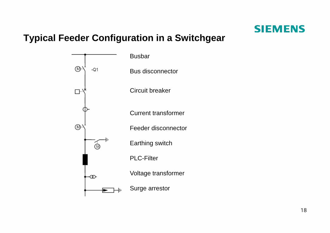
Typical Feeder Configuration in a Switchgear
Busbar
Bus disconnector
Circuit breaker
Current transformer
18
Feeder disconnector
Earthing switch
PLC-Filter
Voltage transformer
Surge arrestor
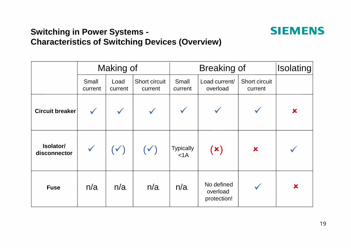
Switching in Power Systems -Characteristics of Switching Devices (Overview)
Making of Breaking of
Circuit breaker
Small current
Short circuit current
Load current
Small current
Load current/overload
Short circuitcurrent
� � � ���
Isolating
�
19
Fuse
Isolator/disconnector � (�) (�) Typically
<1A
n/a. n/a.n/a.n/a. �No definedoverload
protection!
�(�)
�
�
Selection of switching devices
Switching devices are selected both according to their ratings and according to the switching duties to be performed, which also includes the switching rates.
1. Selection according to ratings:
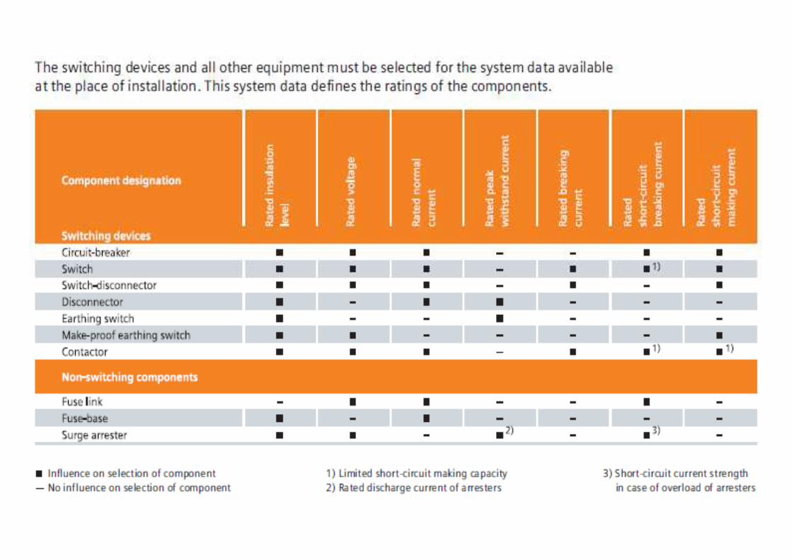
The system conditions, that is, the properties of the primary circuit, determine the required parameters. The most important of these are:
� Rated voltage: The upper limit of the system voltage the device is designed for. Since all
20
� Rated voltage: The upper limit of the system voltage the device is designed for. Since all high-voltage switching devices are zero-current interrupters – except for some fuses –the system voltage is the most important dimensioning criterion. It determines the dielectric stress of the switching device by means of the transient recovery voltage and the recovery voltage, especially while switching off.
� Rated insulation level: The dielectric strength from phase to earth, between phases and across the open contact gap, or across the isolating distance. The dielectric strength is the capability of an electrical component to withstand all voltages with a specific time sequence up to the magnitude of the corresponding withstand voltages.

These can be operating voltages or higher-frequency voltages caused by switching operations, earth faults (internal over-voltages) or lightning strikes (external over-voltages). The dielectric strength is verified by a lightning impulse withstand voltage test with the standard impulse wave of 1.2/50 µs and a power frequency withstand voltage test (50 Hz/1min).
� Rated normal current:
The current that the main circuit of a device can continuously carry under defined
21
The current that the main circuit of a device can continuously carry under defined conditions The temperature increase of components – especially contacts – must not exceed defined values. Permissible temperature increases always refer to the ambient air temperature. If a device is mounted in an enclosure, it may be advisable to load it below its full rated current, depending on the quality of heat dissipation.
� Rated peak withstand current:
The peak value of the major loop of the short-circuit current during a compensation process after the beginning of the current flow, which the device can carry in closed state.
It is a measure for the electro-dynamic (mechanical) load of an electrical component. For devices with full making capacity, this value is not relevant (see next item).
� Rated short-circuit making current:
The peak value of the making current in case of short-circuit at the terminals of the switching device. This stress is greater than that of the rated peak withstand current because dynamic forces may work against the contact movement.
�
22
� Rated breaking current:
The load breaking current in normal operation. For devices with full breaking capacity and without a critical current range, this value is not relevant (see previous item).
� Rated short-circuit breaking current:
The rms value of the breaking current in case of short-circuit at the terminals of the switching device.
23
2. Selection according to endurance and switching r ates:
If several devices satisfy the electrical requirements and no additional criteria have to be taken into account, the required switching rate can be used as an additional selection criterion.
The respective device standards distinguish between classes of mechanical (M) and electrical (E) endurance, whereby they can also be used together on the same switching
24
electrical (E) endurance, whereby they can also be used together on the same switching device: e.g., a switching device can have both mechanical class M1 and electrical class E3.
3. Technical data of Medium -Voltage Switchgear (Assembly)
Most medium-voltage switchgears are indoor units and are selected not as isolated units but as switchgear assembly. The major influences and stress values that a switchgear assembly is subjected to result from the task and its rank in the distribution system. These influencing factors and stresses determine the selection parameters and ratings of the switchgear.
a) Rated voltage and frequency:
The system voltage and frequency determine these values for the switchgear, switching
25
The system voltage and frequency determine these values for the switchgear, switching devices and other installed components. The maximum system voltage at the upper tolerance limit is the deciding factor.
Assigned configuration criteria w.r.t. voltage for switchgear are:
− Rated voltage Ur (kV); frequency f (Hz);
− Rated insulation level [Short-duration power-frequency withstand voltage Ud (kV); Lightning impulse withstand voltage Up (kV)];
− Rated primary voltage of VTs (kV).
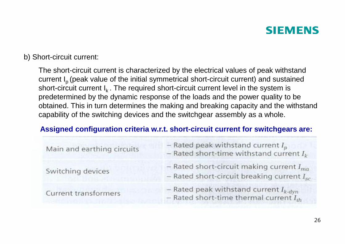
b) Short-circuit current:
The short-circuit current is characterized by the electrical values of peak withstand current Ip (peak value of the initial symmetrical short-circuit current) and sustained short-circuit current Ik . The required short-circuit current level in the system is predetermined by the dynamic response of the loads and the power quality to be obtained. This in turn determines the making and breaking capacity and the withstand capability of the switching devices and the switchgear assembly as a whole.
26
Assigned configuration criteria w.r.t. short-circui t current for switchgears are:
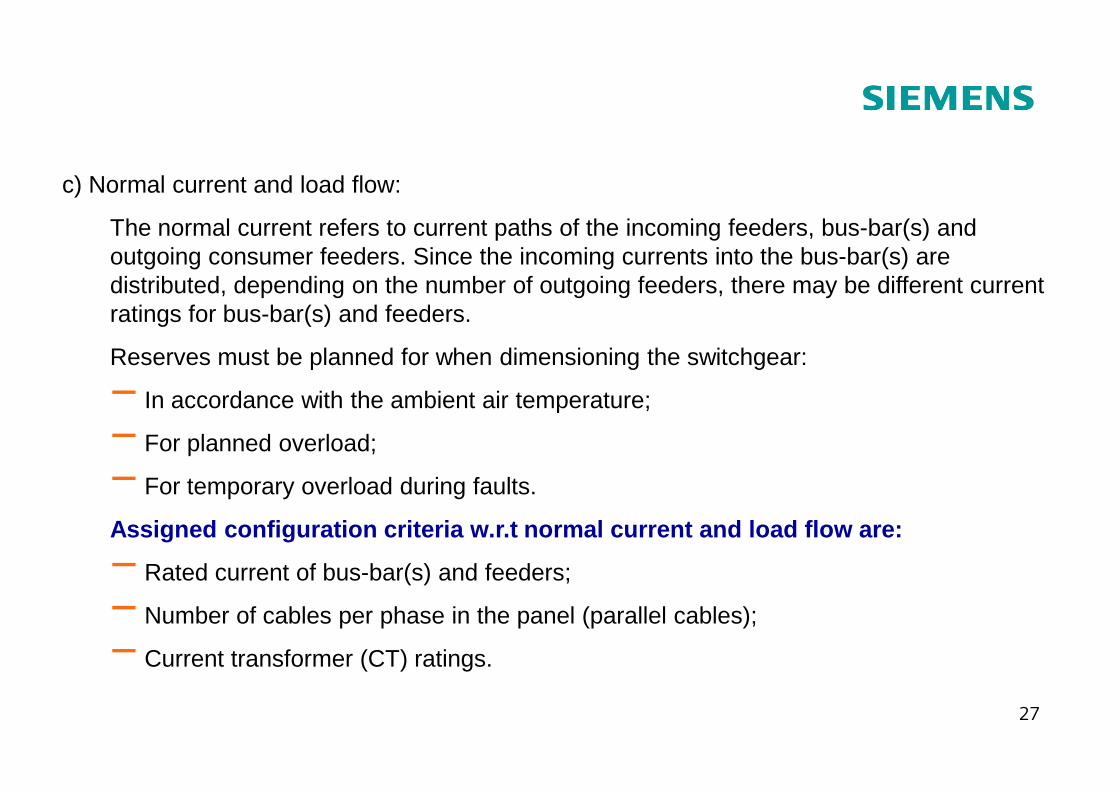
c) Normal current and load flow:
The normal current refers to current paths of the incoming feeders, bus-bar(s) and outgoing consumer feeders. Since the incoming currents into the bus-bar(s) are distributed, depending on the number of outgoing feeders, there may be different current ratings for bus-bar(s) and feeders.
Reserves must be planned for when dimensioning the switchgear:
− In accordance with the ambient air temperature;
27
− In accordance with the ambient air temperature;
− For planned overload;
− For temporary overload during faults.
Assigned configuration criteria w.r.t normal curren t and load flow are:
− Rated current of bus-bar(s) and feeders;
− Number of cables per phase in the panel (parallel cables);
− Current transformer (CT) ratings.
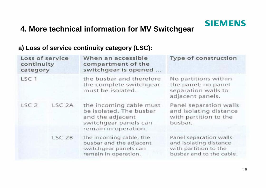
4. More technical information for MV Switchgear
a) Loss of service continuity category (LSC):
28
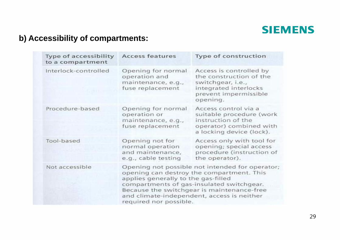
b) Accessibility of compartments:
29
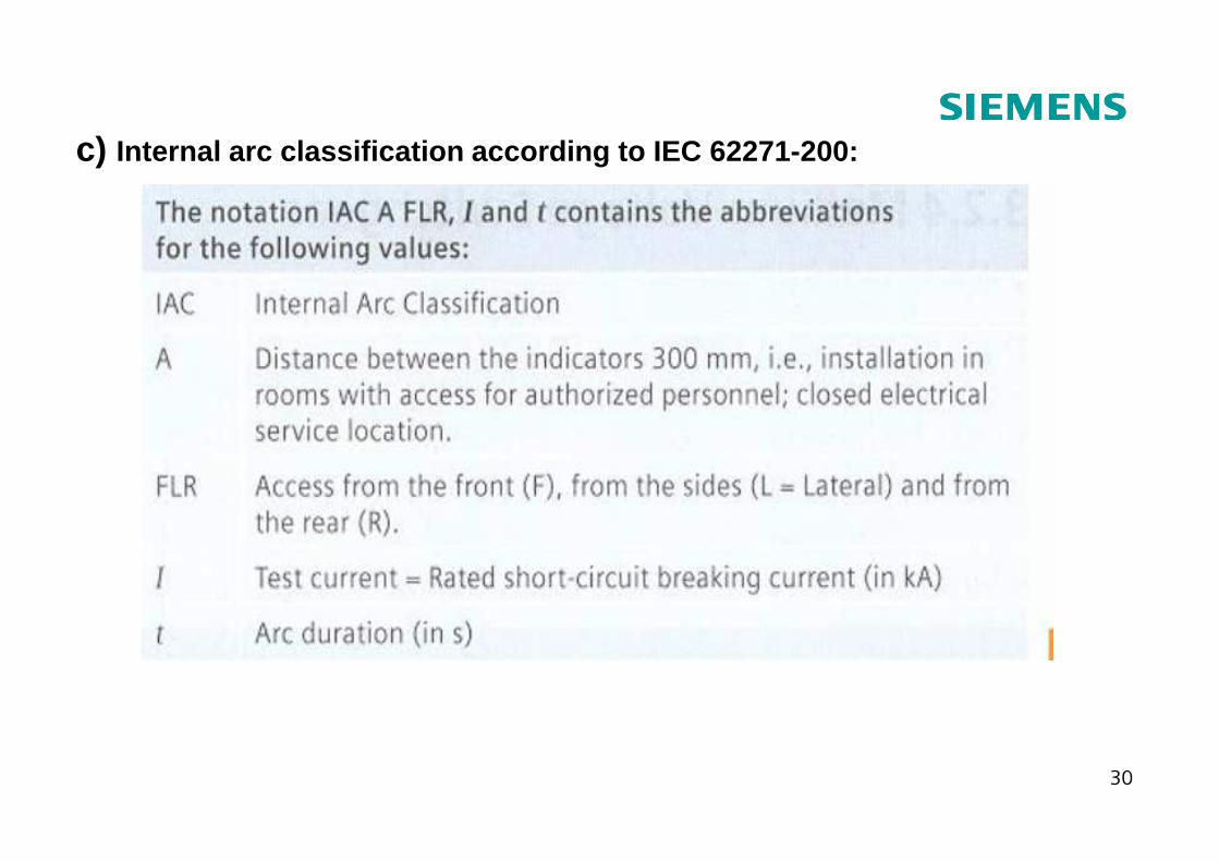
c) Internal arc classification according to IEC 62271- 200:
30
d) Other information
Other information apart from the technical data are:
• Physical dimensions: Width; Height; Depth;
• Type of construction: Extendable or Non-extendable;
• Bus-bar system: Single Bus-bar or Double bus-bar;
• Insulation i.e. Insulating medium;
31
• Insulation i.e. Insulating medium;
• Type of interrupter (if circuit breaker);
• Fixed-mounting, Withdrawable or Truck-type;
• Any special features etc.
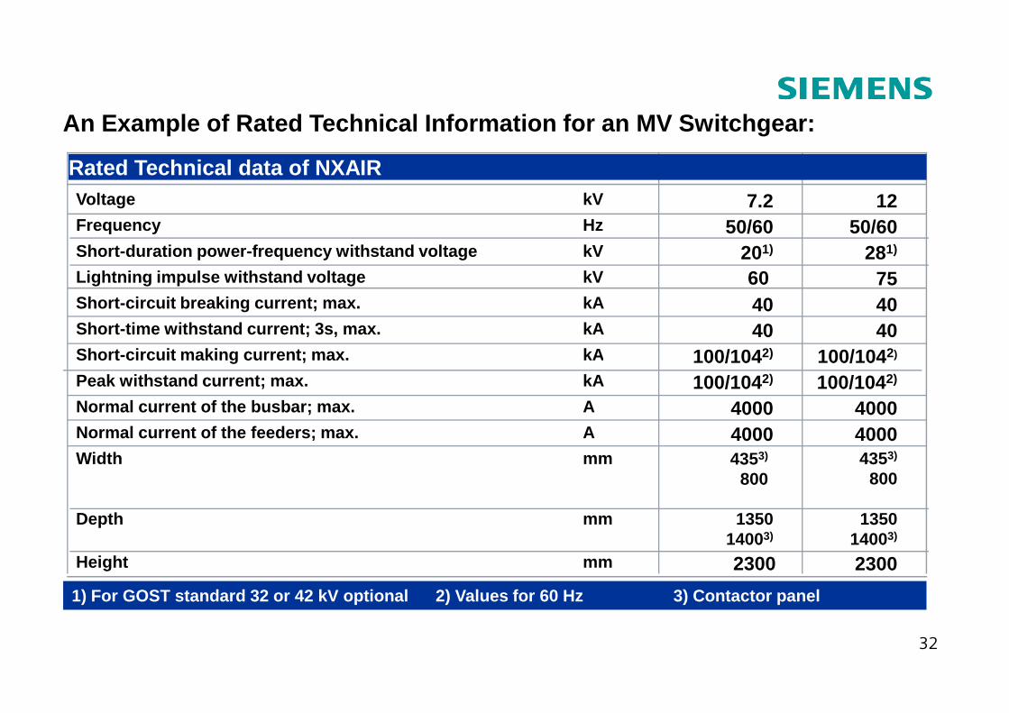
An Example of Rated Technical Information for an MV Switchgear:
kA
kA
kA
kV
kV
Hz
kV
12 kV7.2 kV
100/1042)100/1042)Short -circuit making current; max.4040Short-time withstand current; 3s, max.4040Short-circuit breaking current; max.7560Lightning impulse withstand voltage
281)201)Short-duration power-frequency withstand voltage50/6050/60Frequency
127.2Voltage
Rated Technical data of NXAIR
32
40004000ANormal current of the feeders; max.
4353)
8004353)
800mmWidth
135014003)
135014003)
mmDepth
mm
A
kA
kA
23002300Height
40004000Normal current of the busbar; max.100/1042)100/1042)Peak withstand current; max.100/1042)100/1042)Short -circuit making current; max.
1) For GOST standard 32 or 42 kV optional 2) Values for 60 Hz 3) Contactor panel
5. Circuit Breakers – functions and types
Functions of a Circuit Breaker in an electrical Net work: � Circuit Breakers are like electromechanical switches with a making and breaking
capacity such that they can withstand the stresses which arise when equipment
and parts of an installation are switched on and off under normal and abnormal
conditions for example a short circuit.
� They prevent damage to other parts of equipment like transformers, generators,
33
motors or other expensive components of the substation, by interrupting
high short circuit currents very fast.
� Through fast reclosing, they ensure power restoration within a short time
� Circuit Breakers do not open or close by themselves. The opening and closing
has to be initiated either manually or automatically by protection systems.
� Circuit Breakers are like fuses except that they need not be replaced after every
operation.
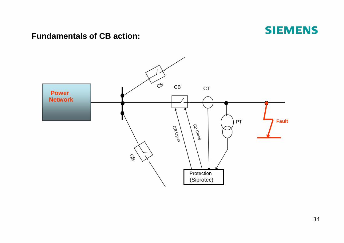
Fundamentals of CB action:
PowerNetwork
CB CT
PT Fault
34
(Siprotec)Protection
PT Fault
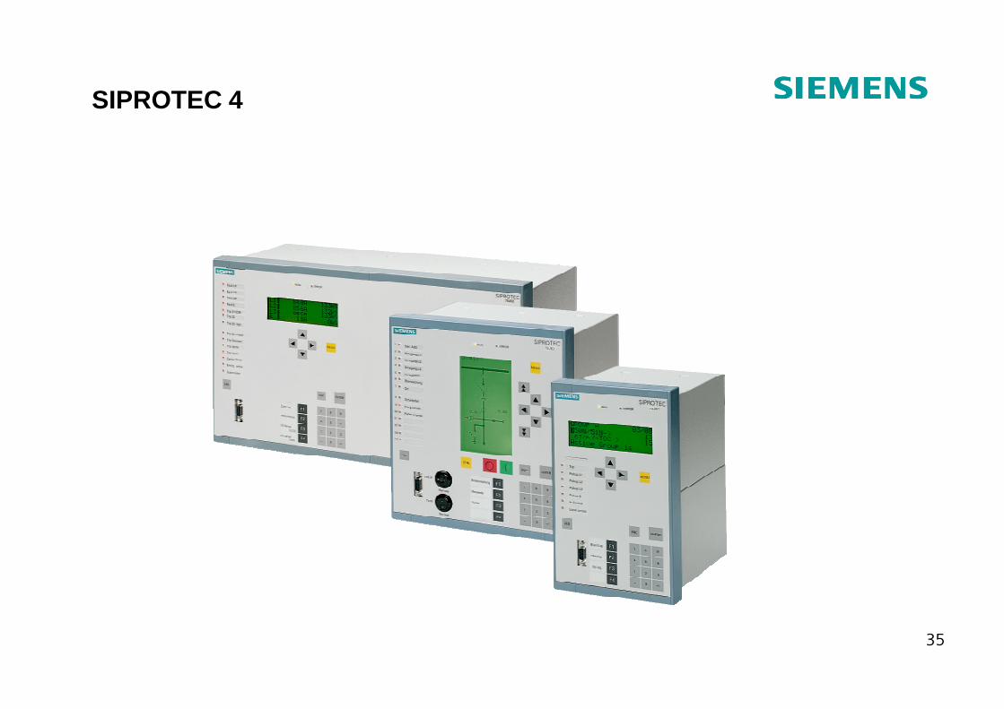
SIPROTEC 4
35
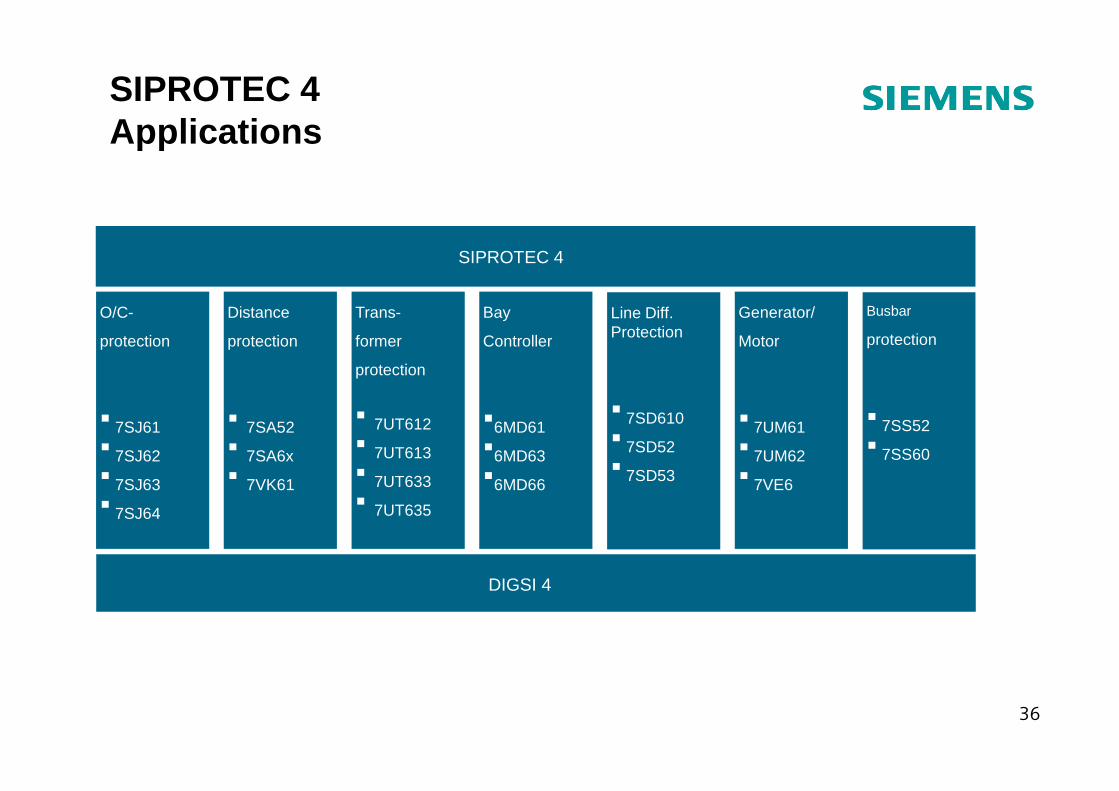
SIPROTEC 4
Busbar
protection
Generator/
Motor
Line Diff.Protection
Distance
protection
O/C-
protection
Trans-
former
protection
Bay
Controller
SIPROTEC 4Applications
36
DIGSI 4
� 7SS52� 7SS60
� 7UM61� 7UM62 � 7VE6
� 7SD610� 7SD52 � 7SD53
� 7SA52� 7SA6x� 7VK61
� 7SJ61� 7SJ62� 7SJ63� 7SJ64
� 7UT612 � 7UT613� 7UT633� 7UT635
�6MD61 �6MD63�6MD66
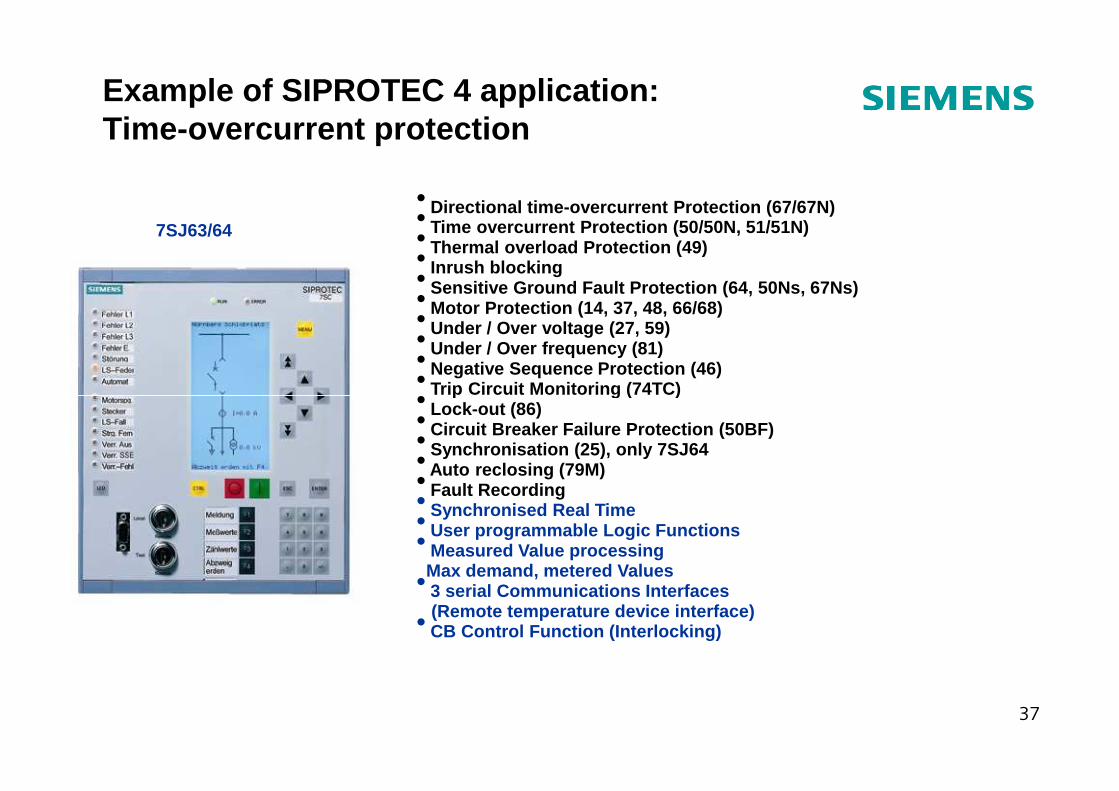
• Directional time-overcurrent Protection (67/67N)• Time overcurrent Protection (50/50N, 51/51N)• Thermal overload Protection (49)• Inrush blocking• Sensitive Ground Fault Protection (64, 50Ns, 67Ns) • Motor Protection (14, 37, 48, 66/68)• Under / Over voltage (27, 59)• Under / Over frequency (81)• Negative Sequence Protection (46) • Trip Circuit Monitoring (74TC) •
7SJ63/64
Example of SIPROTEC 4 application:Time-overcurrent protection
Trip Circuit Monitoring (74TC) • Lock-out (86)• Circuit Breaker Failure Protection (50BF)• Synchronisation (25), only 7SJ64 • Auto reclosing (79M)• Fault Recording• Synchronised Real Time• User programmable Logic Functions• Measured Value processingMax demand, metered Values• 3 serial Communications Interfaces(Remote temperature device interface) • CB Control Function (Interlocking)
37
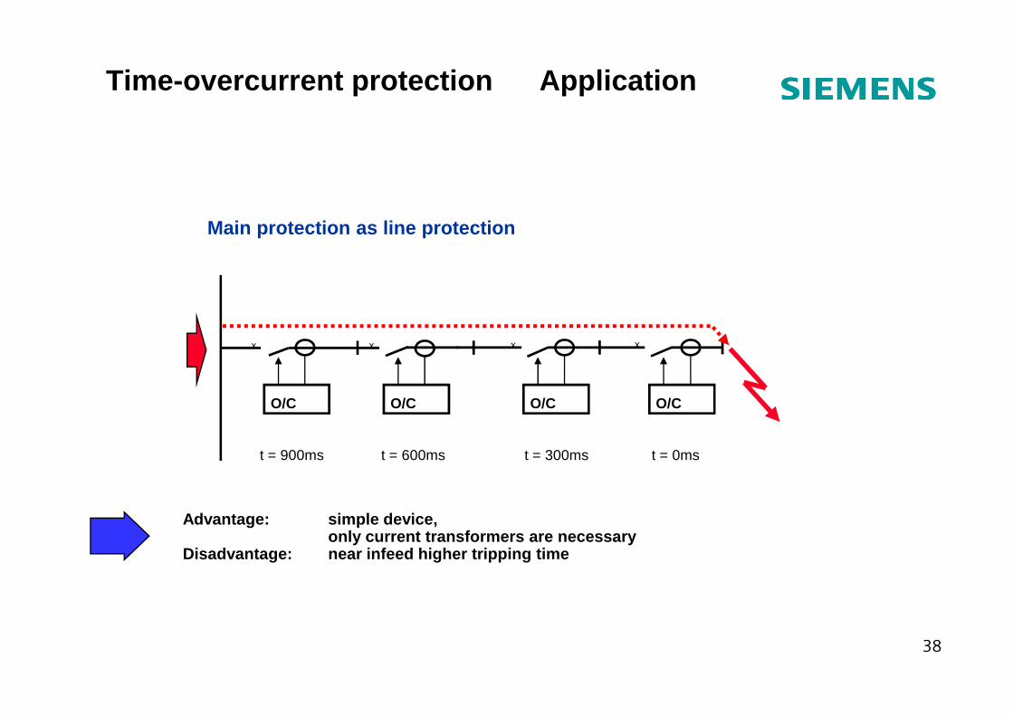
Main protection as line protection
x x x x
Time-overcurrent protection Application
Advantage: simple device,only current transformers are necessary
Disadvantage: near infeed higher tripping time
O/C O/C O/C O/C
t = 0mst = 300mst = 600mst = 900ms
38
t/s0,075 0,100 0,125 0,150 0,175 0,200 0,225
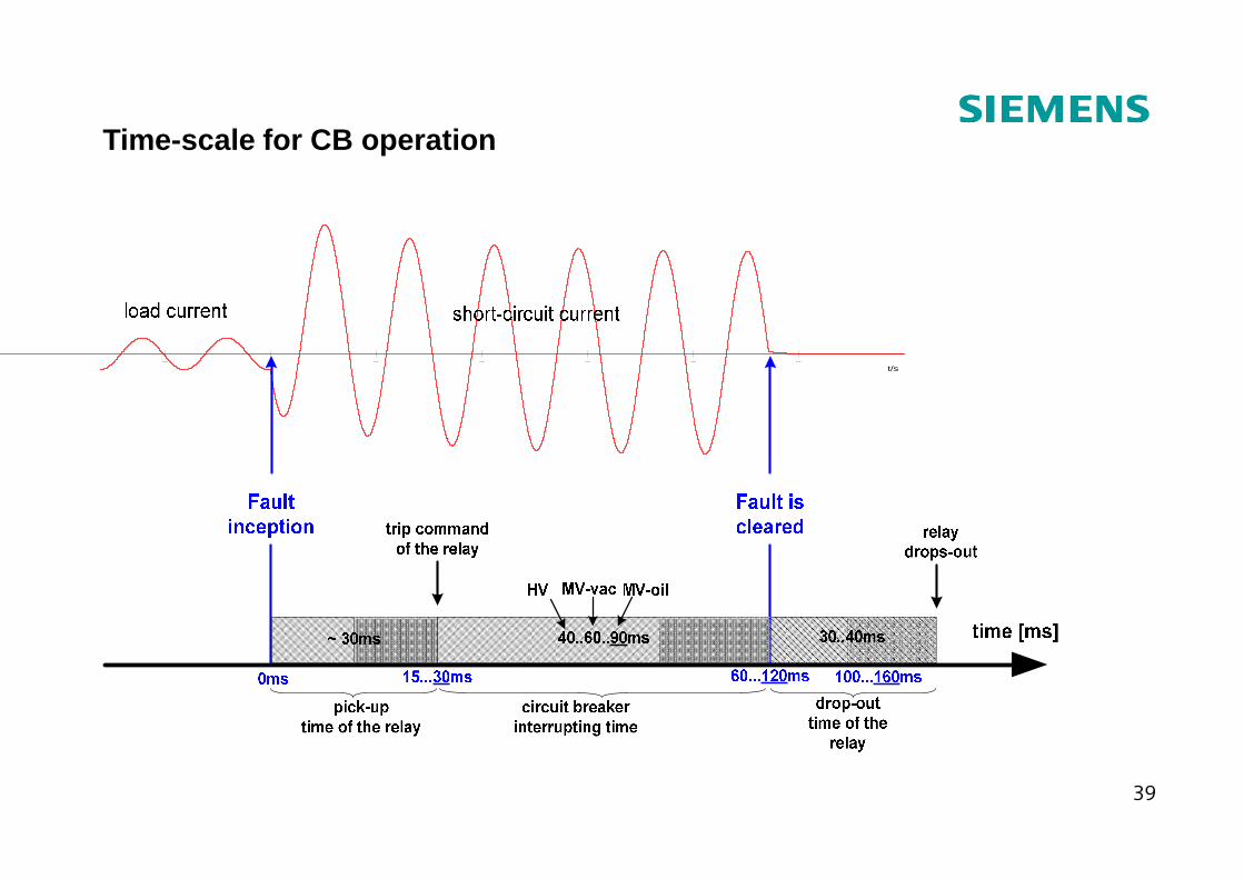
Time-scale for CB operation
39
Types of Circuit Breakers
The following types of breakers were used in Power Systems :
� Bulk oil or Oil filled (Dead Tank and Live Tank);
� Oil filled with minimum volume of oil (MOCB);
� Air Blast; AIS;
� GIS, Sulphur Hexa Flouride SF (Dead Tank and Live Tank);
40
� GIS, Sulphur Hexa Flouride SF6 (Dead Tank and Live Tank);
� Vacuum (generally Medium Voltage)
� Single phase (suited for single phase breaker opening and is
used generally for HV / EHV lines)
In all these cases, except for vacuum, the medium (oil, air or SF6) were used for insulation and arc quenching.
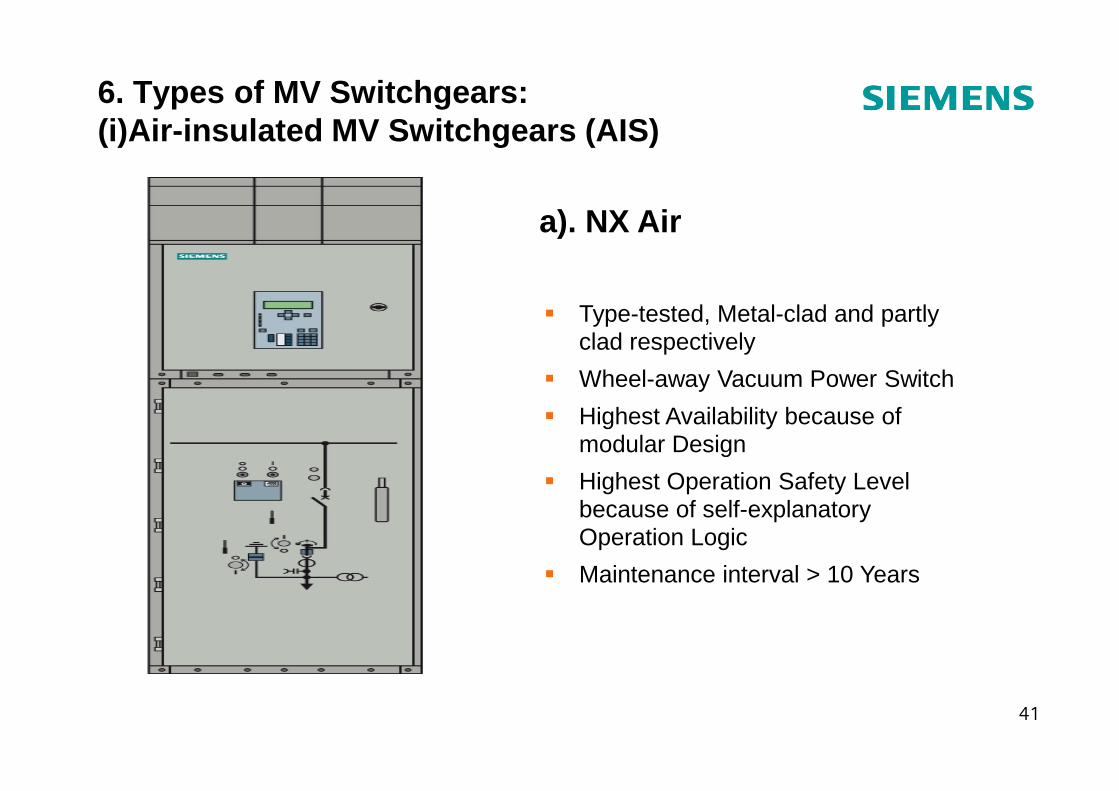
6. Types of MV Switchgears:(i)Air-insulated MV Switchgears (AIS)
� Type-tested, Metal-clad and partly clad respectively
� Wheel-away Vacuum Power Switch
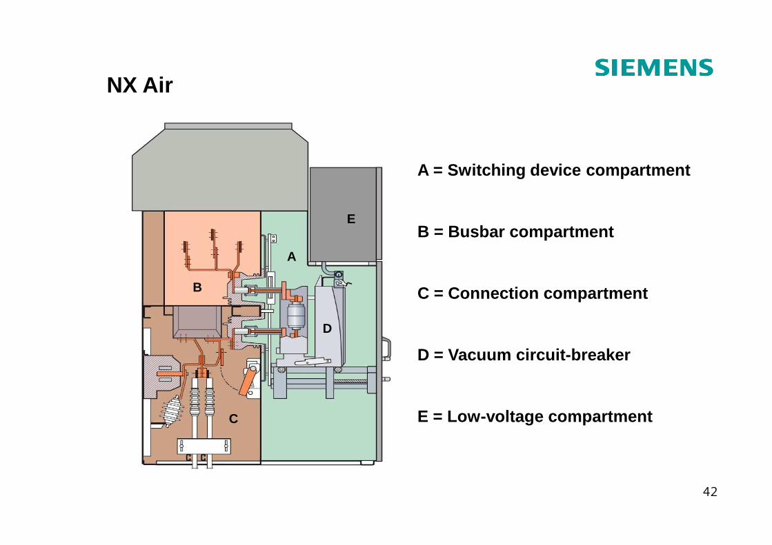
a). NX Air
41
� Highest Availability because of modular Design
� Highest Operation Safety Level because of self-explanatory Operation Logic
� Maintenance interval > 10 Years
A
E
A = Switching device compartment
B = Busbar compartment
NX Air
42
B
C
D
C = Connection compartment
D = Vacuum circuit-breaker
E = Low-voltage compartment
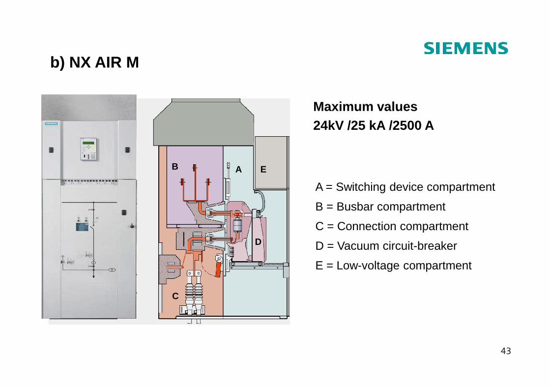
A = Switching device compartment
b) NX AIR M
Maximum values24kV /25 kA /2500 A
AB E
43
B = Busbar compartment
C = Connection compartment
D = Vacuum circuit-breaker
E = Low-voltage compartment
C
D
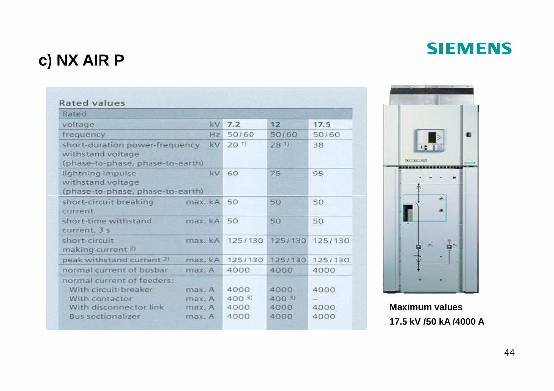
c) NX AIR P
44
Maximum values
17.5 kV /50 kA /4000 A
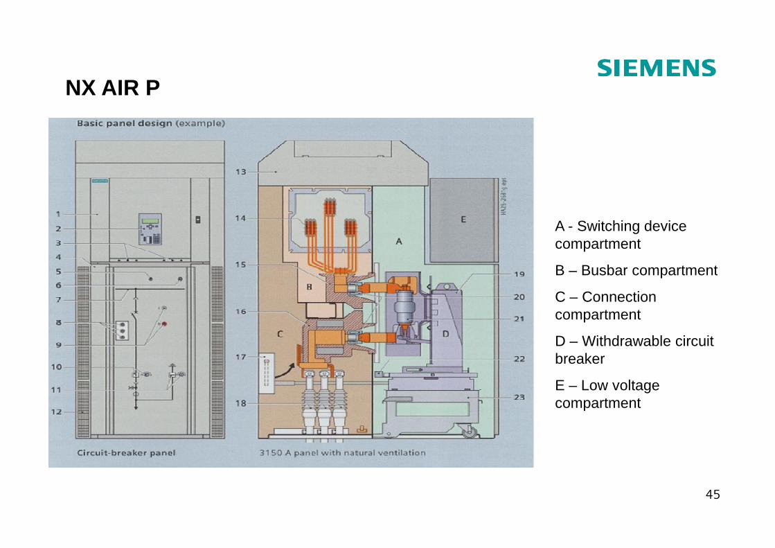
A - Switching device compartment
B – Busbar compartment
NX AIR P
45
B – Busbar compartment
C – Connection compartment
D – Withdrawable circuit breaker
E – Low voltage compartment
Other brands of AIS
� NX AIR S – up to 12kV /40 kA / 3150 A
� SIMOPRIME – up to 17.5 kV / 40 kA / 3600 A
� SIMOPRIME A4 – 24 kV / 25 kA / 2500 A
� 8BT1 – up to 12 kV /25 kA / 2000 A, and 24 kV / 25 kA / 2000 A (LSC 2A)
� 8BT2 – 36 kV / 31.5 kA / 2500 A (LSC 2B)
� 8BT3 – up to 36 kV / 16 kA / 1250 A (LSC1)
46
� 8BT3 – up to 36 kV / 16 kA / 1250 A (LSC1)
� 8BK80 – up to 15 kV / 44 kA / 3150 A and 8BK80 – 36 kV / 31.5 kA /2000 A
� 8BK88 PLUS up to 12 kV / 25 kA / 1600 A
� GM SG – up to 15 kV / 63 kA / 4000 A
� GM 38 – 38 kV / 31.5 kA / 2500 A
� SIMOSEC – up to 24 kV and up to 1250 A. Have vacuum CB and the three-position earthing switch inside a sealed pressure switchgear vessel with SF6 for entire service life.
Switchgear type NXAIR NXAIR M NXAIR P
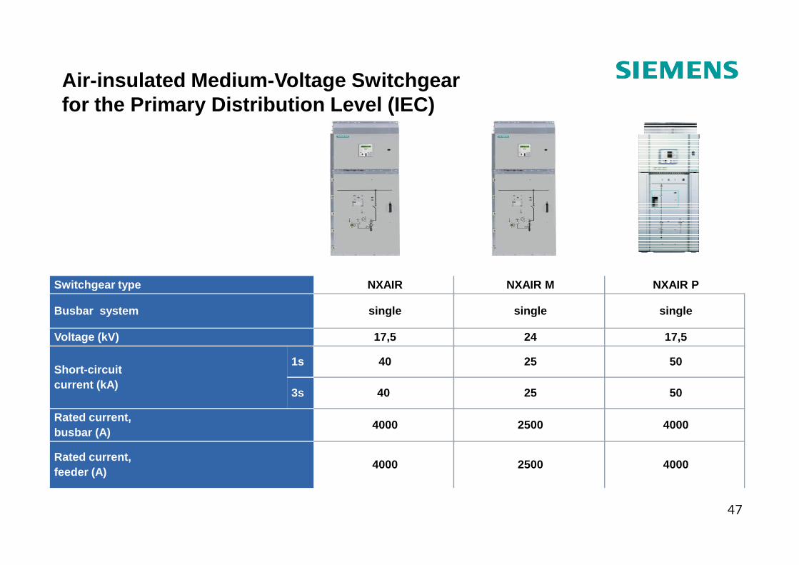
Air-insulated Medium -Voltage Switchgear for the Primary Distribution Level (IEC)
47
Switchgear type NXAIR NXAIR M NXAIR P
Busbar system single single single
Voltage (kV) 17,5 24 17,5
Short-circuit current (kA)
1s 40 25 50
3s 40 25 50
Rated current, busbar (A)
4000 2500 4000
Rated current, feeder (A)
4000 2500 4000
Switchgear type SIMOPRIME 8BT1 8BT2 8BT3
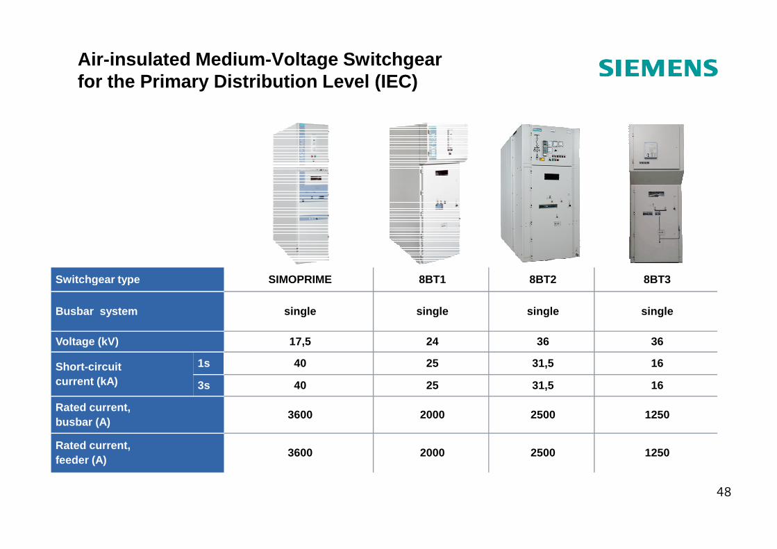
Air-insulated Medium -Voltage Switchgear for the Primary Distribution Level (IEC)
48
Switchgear type SIMOPRIME 8BT1 8BT2 8BT3
Busbar system single single single single
Voltage (kV) 17,5 24 36 36
Short-circuit current (kA)
1s 40 25 31,5 16
3s 40 25 31,5 16
Rated current, busbar (A)
3600 2000 2500 1250
Rated current, feeder (A)
3600 2000 2500 1250
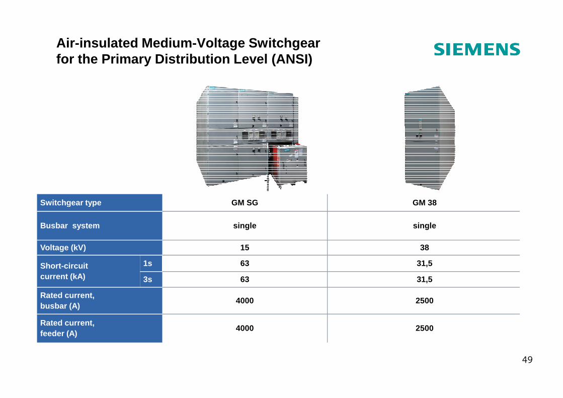
Air-insulated Medium -Voltage Switchgear for the Primary Distribution Level (ANSI)
Switchgear type GM SG GM 38
49
Switchgear type GM SG GM 38
Busbar system single single
Voltage (kV) 15 38
Short-circuit current (kA)
1s 63 31,5
3s 63 31,5
Rated current, busbar (A)
4000 2500
Rated current, feeder (A)
4000 2500
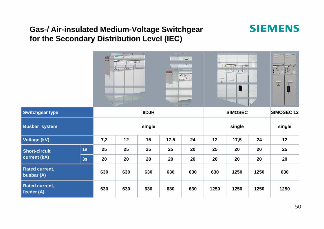
Gas-/ Air-insulated Medium -Voltage Switchgear for the Secondary Distribution Level (IEC)
Switchgear type SIMOSEC 12SIMOSEC8DJH
50
Rated current, feeder (A)
Rated current, busbar (A)
Short-circuit current (kA)
Voltage (kV)
Busbar system
Switchgear type
3s
1s
1250125012501250630630630630630
63012501250630630630630630630
202020202020202020
252020252025252525
122417,5122417,515127,2
singlesinglesingle
SIMOSEC 12SIMOSEC8DJH
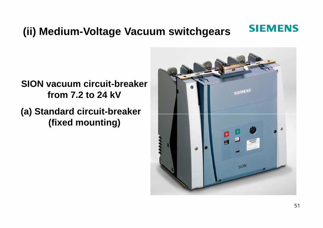
(ii) Medium -Voltage Vacuum switchgears
SION vacuum circuit-breaker from 7.2 to 24 kV
(a) Standard circuit -breaker
51
(a) Standard circuit -breaker (fixed mounting)
SION vacuum circuit-breaker from 7.2 to 24 kV
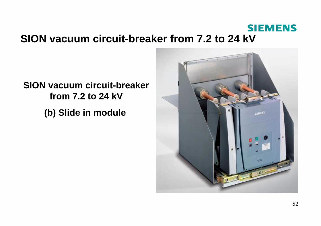
SION vacuum circuit-breaker from 7.2 to 24 kV
(b) Slide in module
52
(b) Slide in module
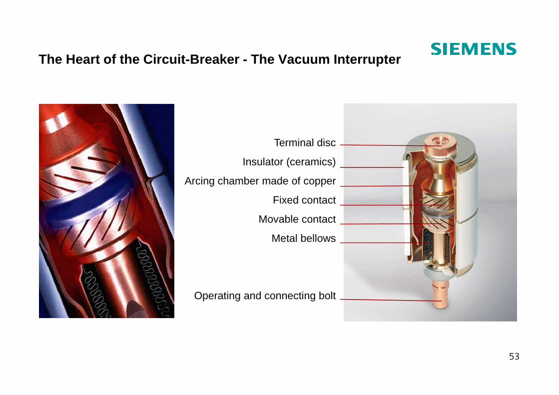
The Heart of the Circuit-Breaker - The Vacuum Interr upter
Terminal disc
Insulator (ceramics)
Arcing chamber made of copper
Fixed contact
53
Fixed contact
Movable contact
Metal bellows
Operating and connecting bolt
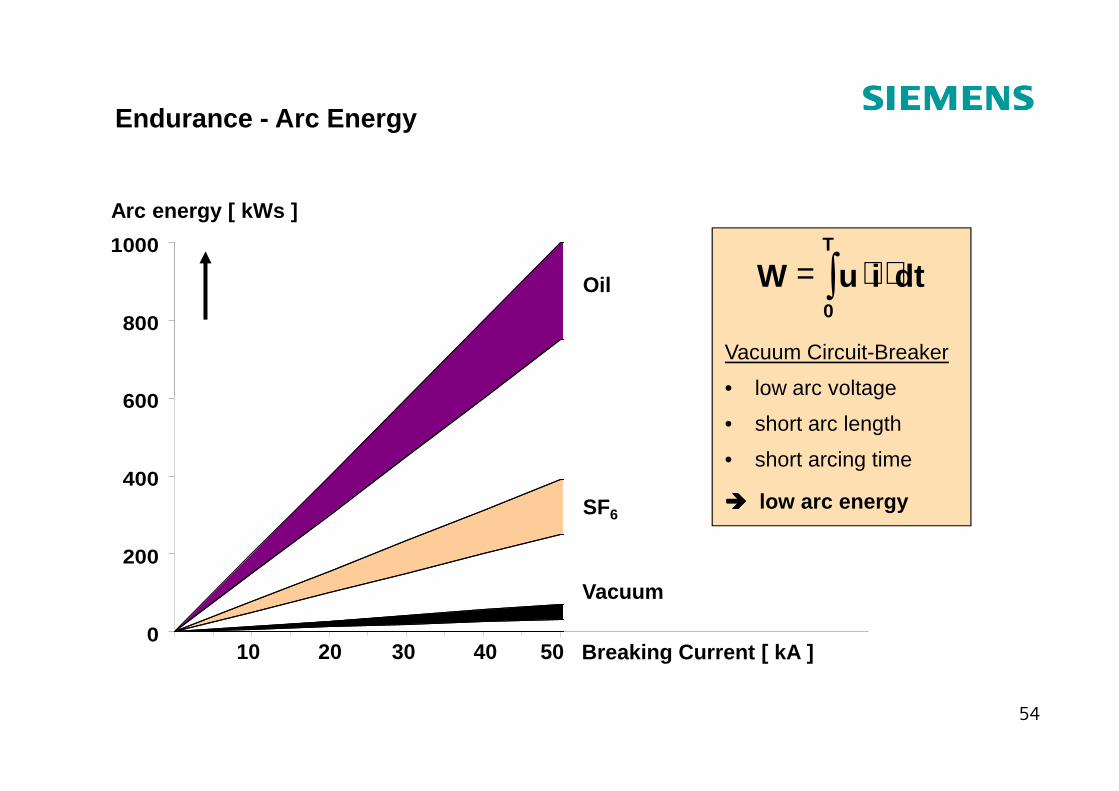
Endurance - Arc Energy
∫ ⋅⋅=T
0
dtiuW
Vacuum Circuit-Breaker
• low arc voltage600
800
1000
Oil
Arc energy [ kWs ]
54
• low arc voltage
• short arc length
• short arcing time
���� low arc energy
0
200
400
600
SF6
Vacuum
Breaking Current [ kA ]5040302010
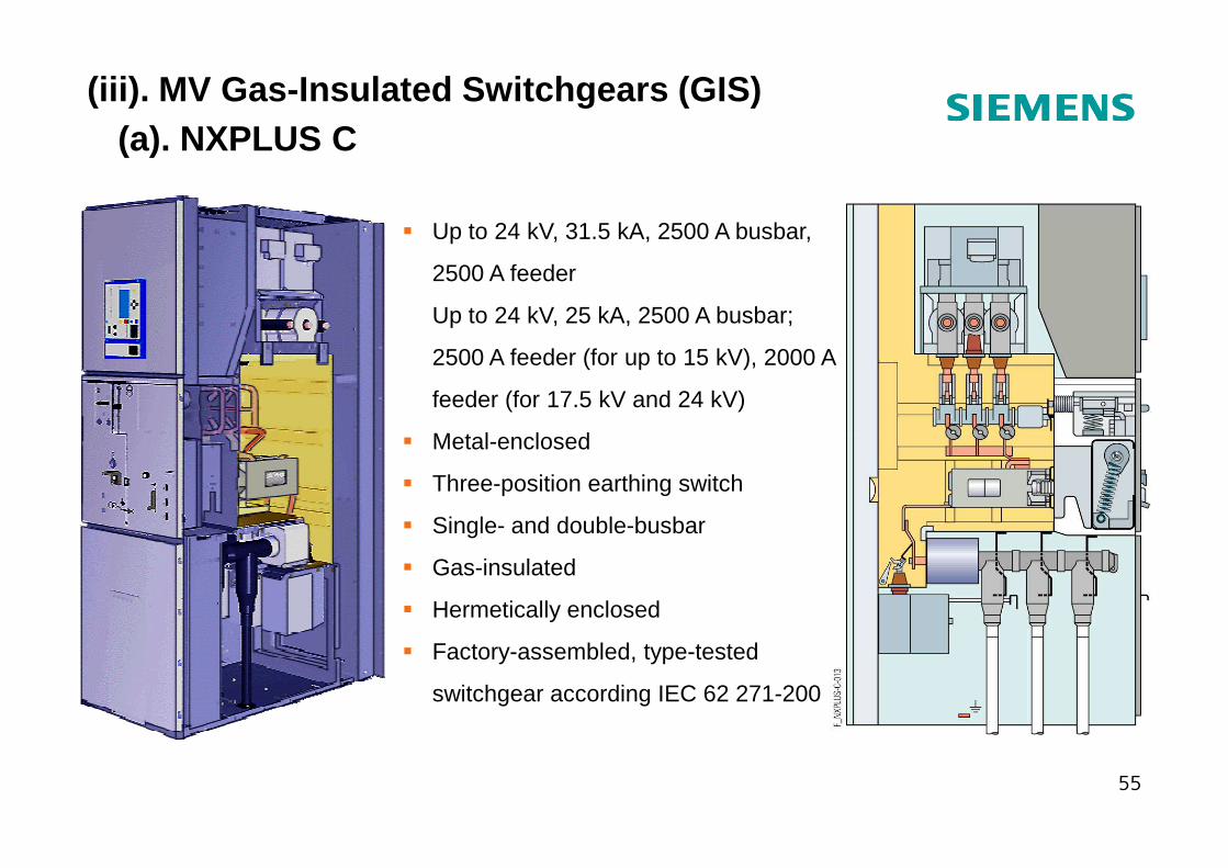
(a). NXPLUS C
� Up to 24 kV, 31.5 kA, 2500 A busbar,
2500 A feeder
Up to 24 kV, 25 kA, 2500 A busbar;
2500 A feeder (for up to 15 kV), 2000 A
feeder (for 17.5 kV and 24 kV)
� Metal-enclosed
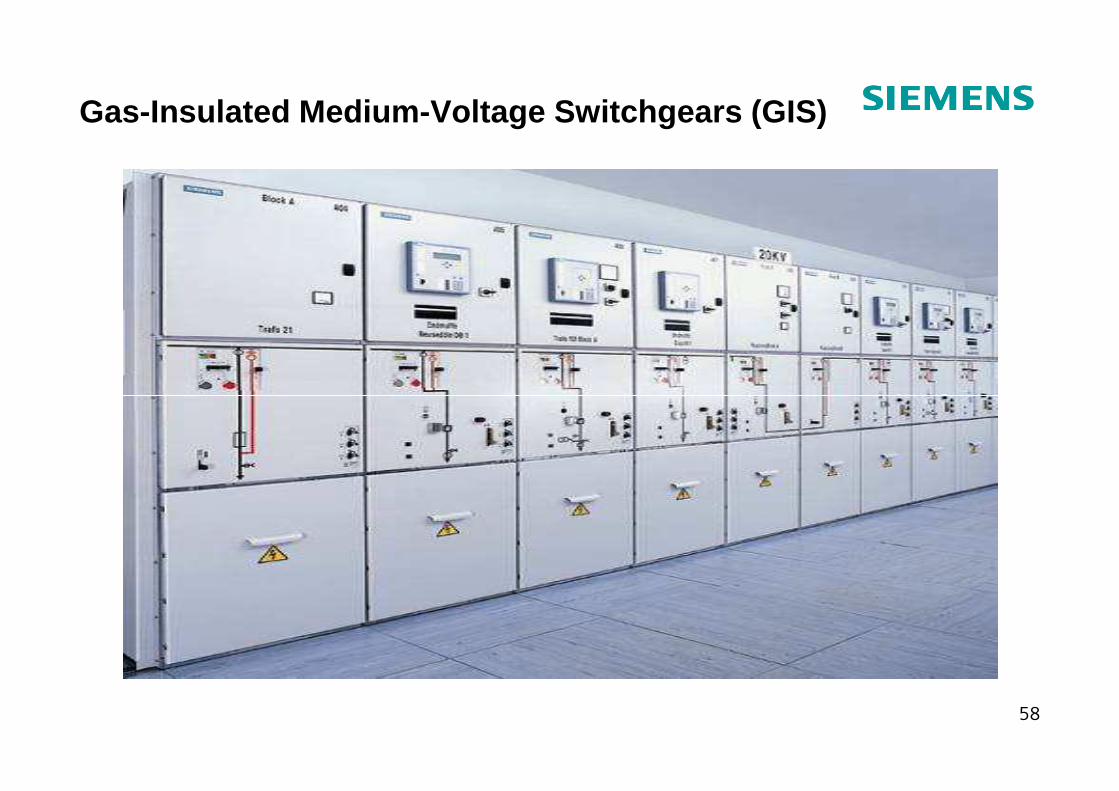
(iii). MV Gas-Insulated Switchgears (GIS)
55
� Metal-enclosed
� Three-position earthing switch
� Single- and double-busbar
� Gas-insulated
� Hermetically enclosed
� Factory-assembled, type-tested
switchgear according IEC 62 271-200
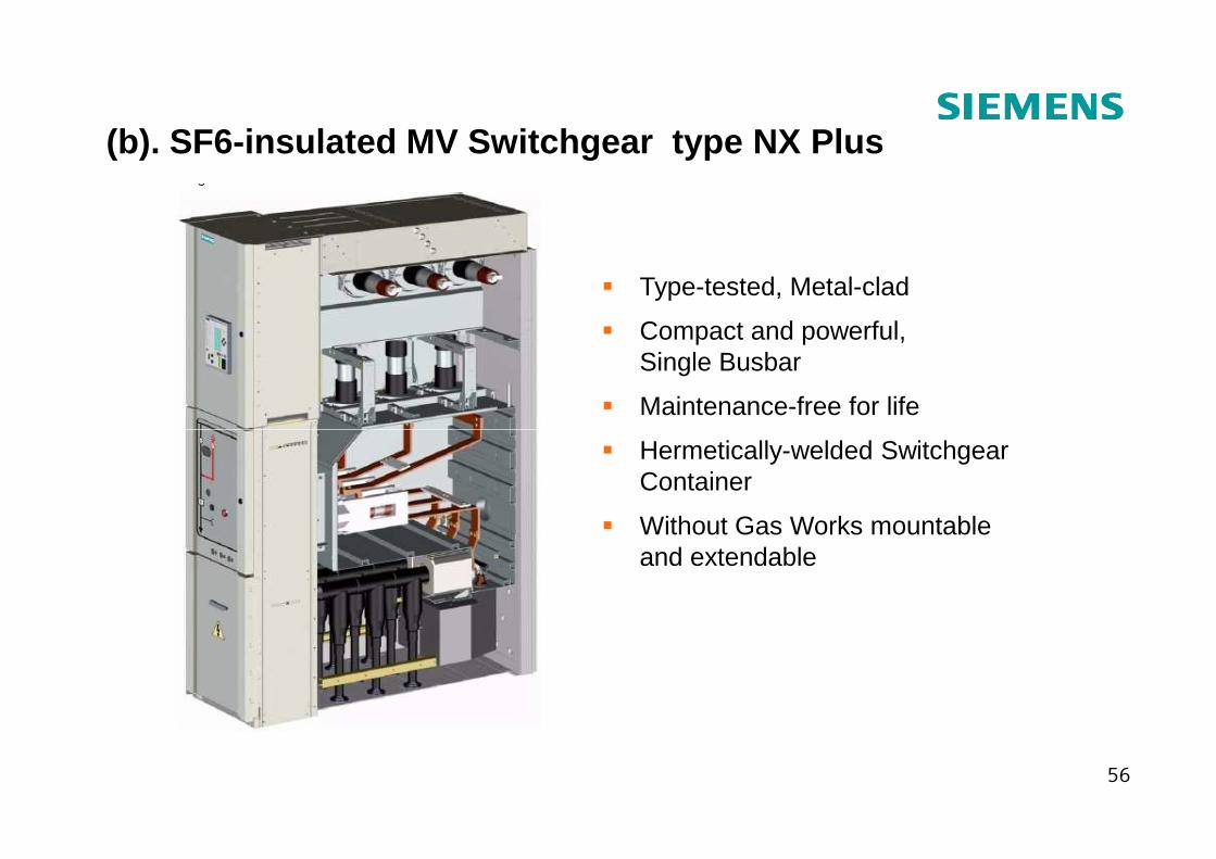
� Type-tested, Metal-clad
� Compact and powerful, Single Busbar
� Maintenance-free for life
(b). SF6-insulated MV Switchgear type NX Plus
56
� Hermetically-welded Switchgear Container
� Without Gas Works mountable and extendable
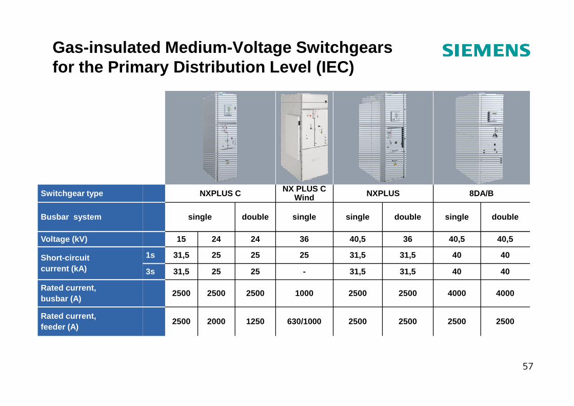
Gas-insulated Medium -Voltage Switchgears for the Primary Distribution Level (IEC)
8DA/BNXPLUSNX PLUS CWindNXPLUS CSwitchgear type
57
1250
2500
25
25
24
double
2500250025002500630/100020002500Rated current, feeder (A)
4000400025002500100025002500Rated current, busbar (A)
404031,531,5-2531,53s
404031,531,5252531,51sShort-circuit current (kA)
40,540,53640,5362415Voltage (kV)
doublesingledoublesinglesinglesingleBusbar system
Gas-Insulated Medium -Voltage Switchgears (GIS)
58
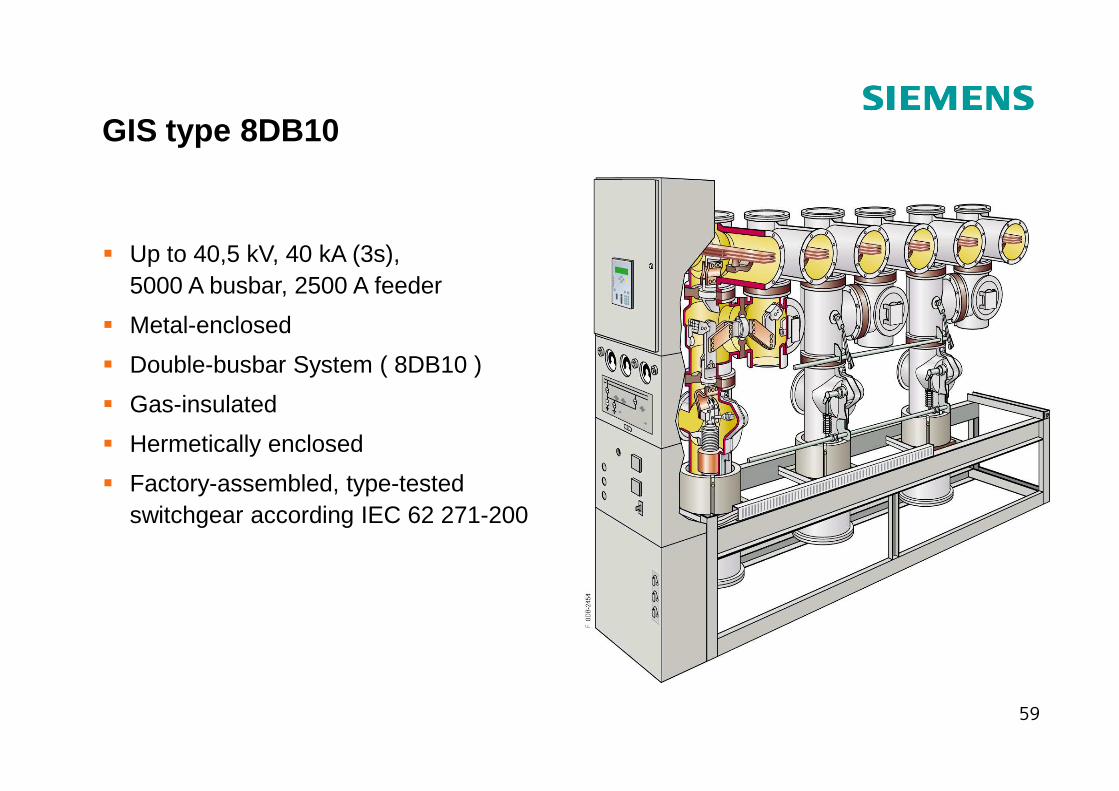
GIS type 8DB10
� Up to 40,5 kV, 40 kA (3s), 5000 A busbar, 2500 A feeder
� Metal-enclosed
� Double-busbar System ( 8DB10 )
� Gas-insulated
59
� Gas-insulated
� Hermetically enclosed
� Factory-assembled, type-tested switchgear according IEC 62 271-200
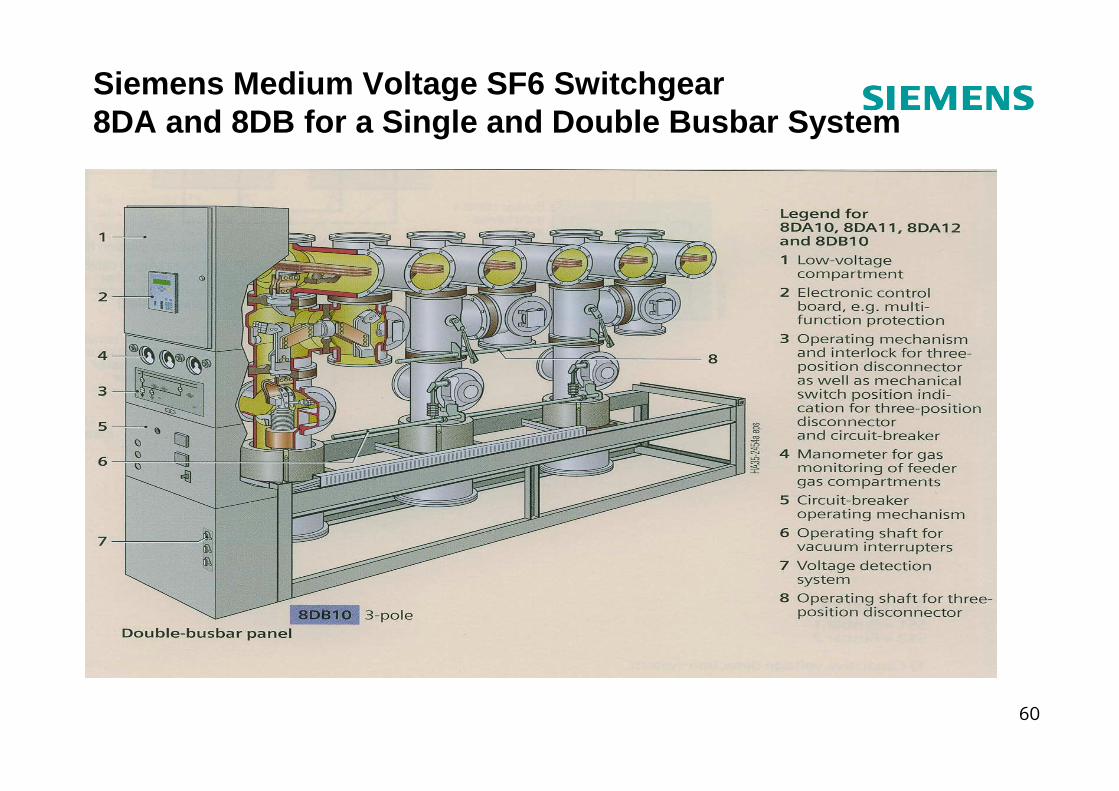
Siemens Medium Voltage SF6 Switchgear 8DA and 8DB for a Single and Double Busbar System
60
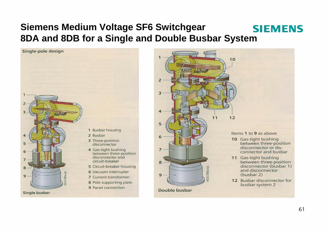
Siemens Medium Voltage SF6 Switchgear 8DA and 8DB for a Single and Double Busbar System
61
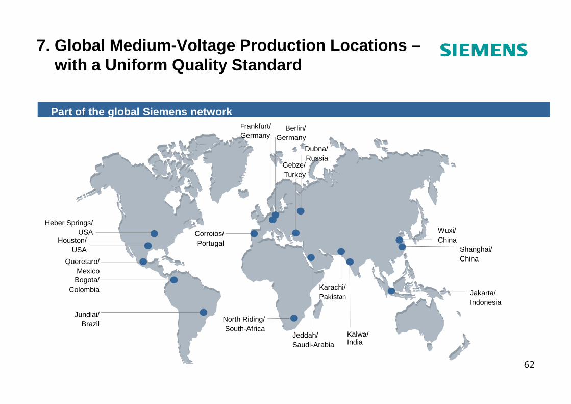
7. Global Medium -Voltage Production Locations –with a Uniform Quality Standard
Frankfurt/Germany
Gebze/Turkey
Berlin/Germany
Part of the global Siemens network
Dubna/Russia
62
Corroios/Portugal
Karachi/Pakistan
Kalwa/ India
Jakarta/ Indonesia
Queretaro/Mexico
Jundiai/Brazil
Bogota/Colombia
Wuxi/China
Shanghai/China
North Riding/South-Africa
Jeddah/Saudi-Arabia
Houston/USA
Heber Springs/USA
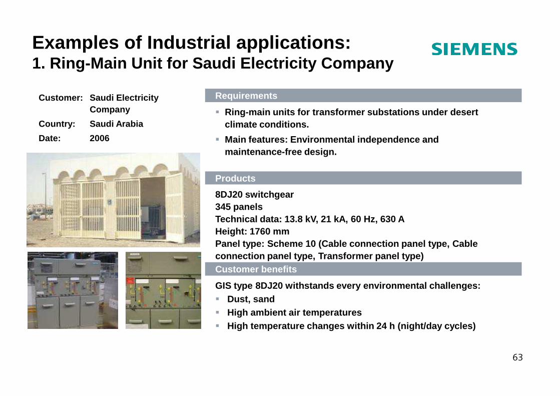
Customer: Saudi Electricity Company
Country: Saudi Arabia
Date: 2006
Requirements
� Ring-main units for transformer substations under d esert climate conditions.
� Main features: Environmental independence and maintenance-free design.
Products
8DJ20 switchgear
Examples of Industrial applications:1. Ring-Main Unit for Saudi Electricity Company
63
8DJ20 switchgear345 panelsTechnical data: 13.8 kV, 21 kA, 60 Hz, 630 AHeight: 1760 mmPanel type: Scheme 10 (Cable connection panel type, Cable connection panel type, Transformer panel type)Customer benefits
GIS type 8DJ20 withstands every environmental chall enges:� Dust, sand� High ambient air temperatures� High temperature changes within 24 h (night/day cyc les)
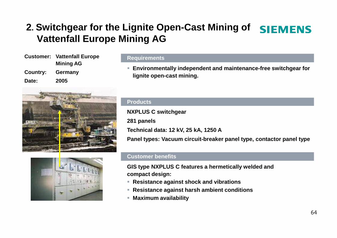
Customer: Vattenfall EuropeMining AG
Country: Germany
Date: 2005
Requirements
� Environmentally independent and maintenance-free sw itchgear for lignite open-cast mining.
Products
NXPLUS C switchgear
281 panels
2. Switchgear for the Lignite Open-Cast Mining of Vattenfall Europe Mining AG
64
281 panels
Technical data: 12 kV, 25 kA, 1250 A
Panel types: Vacuum circuit-breaker panel type, con tactor panel type
Customer benefits
GIS type NXPLUS C features a hermetically welded an d compact design:� Resistance against shock and vibrations� Resistance against harsh ambient conditions� Maximum availability
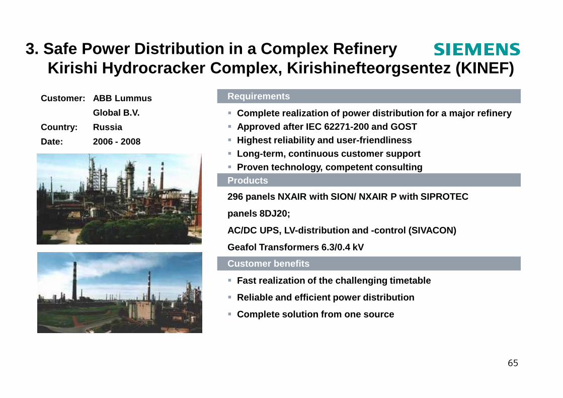
Customer: ABB Lummus
Global B.V.
Country: Russia
Date: 2006 - 2008
Requirements
� Complete realization of power distribution for a ma jor refinery � Approved after IEC 62271-200 and GOST� Highest reliability and user-friendliness� Long-term, continuous customer support� Proven technology, competent consultingProducts
296 panels NXAIR with SION/ NXAIR P with SIPROTEC
3. Safe Power Distribution in a Complex RefineryKirishi Hydrocracker Complex, Kirishinefteorgsentez (KINEF)
65
296 panels NXAIR with SION/ NXAIR P with SIPROTEC
panels 8DJ20;
AC/DC UPS, LV-distribution and -control (SIVACON)
Geafol Transformers 6.3/0.4 kV
Customer benefits
� Fast realization of the challenging timetable
� Reliable and efficient power distribution
� Complete solution from one source
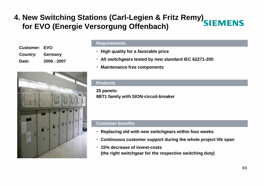
Customer: EVO
Country: Germany
Date: 2006 - 2007
Requirements
� High quality for a favorable price
� All switchgears tested by new standard IEC 62271-20 0
� Maintenance free components
Products
25 panels:
4. New Switching Stations (Carl-Legien & Fritz Remy) for EVO (Energie Versorgung Offenbach)
66
25 panels:8BT1 family with SION-circuit-breaker
Customer benefits
� Replacing old with new switchgears within four week s
� Continuous customer support during the whole projec t life span
� 15% decrease of invest-costs (the right switchgear for the respective switching duty)
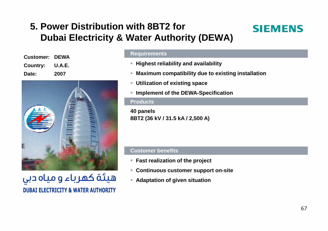
Customer: DEWA
Country: U.A.E.
Date: 2007
Requirements
� Highest reliability and availability
� Maximum compatibility due to existing installation
� Utilization of existing space
� Implement of the DEWA-Specification
Products
40 panels8BT2 (36 kV / 31.5 kA / 2,500 A)
5. Power Distribution with 8BT2 forDubai Electricity & Water Authority (DEWA)
67
8BT2 (36 kV / 31.5 kA / 2,500 A)
Customer benefits
� Fast realization of the project
� Continuous customer support on-site
� Adaptation of given situation
Siemens Power Academy Lagos
68
Seite 68
THANK YOU FOR YOUR ATTENTION
Recommended