
2014 Ford Fusion
MyFord Touch additional Sub/Amp Install Joe Stillman - 2/20/16 [email protected]
Introduction
This document describes my installation procedure for adding an additional amplifier to power an additional subwoofer in a 2014 Ford Fusion with the factory optioned 12 speaker Sony MyFord Touch system. The MyFord Touch system does not allow for aftermarket additions. It contains no RCA cables, remote amps or any other places to tap into for easy signal output. Because of this, an active signal processor is required to tap directly into the main speaker wires in order to add additional amplifiers. Bass Roll Off Something to note about this system (and may other factory car audio systems) is that this system self protects itself from high volume abuse and automatically rolls the bass off as your turn the volume higher. What this means is that the higher your turn up the volume, the system will automatically lower the gains of the bass frequencies. This helps protect the speakers at high volume levels so that they will last longer and/or not get blown from extended periods of high volume levels. Because of this you will need to purchase an active signal processor that can correct and adjust for bass roll off so that this same effect is not fed into your amplifier. Getting Started This document will assume that you have some basic working knowledge of how to carefully remove certain parts of your vehicle, such as the battery, and how to carefully remove interior trim without breaking the plastic clips and standoffs on them. This document will not go into detail of how to remove these parts, but will instead focus on the additional audio components and the installation of them. This guide also assumes you have basic tools such as screw drivers of various sizes, needle nose pliers of various sizes, a TORX bit set with large bits and a socket set. The one nice part of this project is that you only need to run one single cable from the battery to the trunk. Everything else is handled by the active signal processor. Parts Needed:
Active Signal Processor AudioControl LC2i - 2 Channel line out converter with AccuBass and Subwoofer Control $63 on Amazon (as of this writing). There is also a 4 channel processor as well, so purchase for your own needs. There are other brands and models available. Shop accordingly but make sure it’s an active (powered) processor, has a Remote Wire output and allows for Bass Roll Off correction.
Amp Wiring Kit (or equivalent parts). Make sure your wire gauge is rated to the correct amount of power you plan to run for your amp. I used a power cable, ground cable, stereo RCA cables, and some speaker wire (all of which I had laying around from previous projects)
Amplifier (your choice)
Subwoofer w/enclosure (your choice)
Estimated Install Times The times below are adjusted to what I think I would be able to complete each task again if I had already known some of the tips and tricks. Running the power cable through the fire is the most frustrating and difficult part of this project, but with some tips, I hope to make it easier. I gathered some of my information from various car forums and other internet web searches. There are 2 stages to this project, with an optional 3rd stage that can be done at the same time as the 1st stage.
Stage 1 - Running Power Cable o Approx. 30-45mins
Stage 1.5 - (Optional) Installing Signal Processor gain adjustment controller o Approx. - Can do with Stage 1, add additional 10-15mins for running wire. Mounting may take much longer and will not be
covered in this guide as I have not yet completed this part of the task myself. o This will be done during the end of Stage 1, before you reinstall your trim panels.
Stage 2 - Installing Signal Processor, Amp and Sub o Approx. 1-2hrs
Stage 1 - Running Power Cable In order to power your signal processor and amplifier(s) in the trunk area, you will need to run a power cable from the battery all the way to the trunk. This is best accomplished by utilizing the following steps:
1. Remove Battery. The grommet you will be pushing the cable through in the firewall is located directly behind the anti-lock brake system’s tubes, which is located directly behind the battery. There is no other way to get to it without removing the battery.
[Need Photo with battery removed and wire pushed through]
2. Next you will be working under the driver’s side dash. Move your driver’s seat all the way back to allow for more room to work. You will need a flashlight to shine up under the dash.
3. Take a metal coat hanger and cut a long piece off (or use a thin but long screwdriver). Using electrical tape, tape the power cable about an inch below the end of the coat hanger piece (or screwdriver tip). Spiral the tape from just in front of the coat hanger, over the end of the cable, to an inch or two past. This will give the leading edge a nice blunt but pointed and smooth end to poke through the grommet in the firewall.
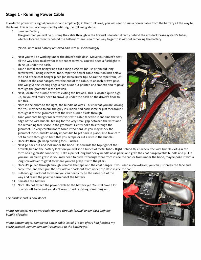
4. Next, locate the bundle of wires exiting the firewall. This is located quite high up, so you will really need to crawl up under the dash on the driver's floor to see this.
5. Note in the photo to the right, the bundle of wires. This is what you are looking for. You may need to pull the grey insulation pad back some or just feel around through it for the grommet that the wire bundle exists through.
6. Take your coat hanger (or screwdriver) with cable taped to it and find the very edge of the wire bundle, feeling for the very small gap between the wires and the remaining free space in the grommet. Gently poke this through the grommet. Be very careful not to force it too hard, as you may knock the grommet loose, and it’s nearly impossible to get back in place. Also take care not to push through so hard that you scrape or cut a wire in the bundle.
7. Once it’s through, keep pushing for 6+ inches. 8. Next go back out and look under the hood. Up towards the top right of the
firewall, behind the battery location you will see a bunch of metal tubes. Right behind this is where the wire bundle exits (in the form of a big plastic connector). Take a pair of long but heavy needle nose pliers and grab the coat hanger/cable bundle and pull. If you are unable to grasp it, you may need to push it through more from inside the car, or from under the hood, maybe poke it with a long screwdriver to get it to where you can grasp it with the pliers.
9. Once it’s pulled through enough, remove the tape and the coat hanger. If you used a screwdriver, you can just break the tape and cable free, and then pull the screwdriver back out from under the dash inside the car.
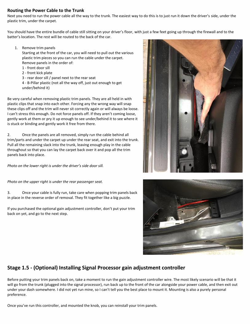
10. Pull enough slack out to where you can neatly route the cable out of the way and reach the positive terminal of the battery.
11. Reinstall the battery. 12. Note: Do not attach the power cable to the battery yet. You still have a lot
of work left to do and you don’t want to risk shorting something out.
The hardest part is now done!
Photo Top Right: red power cable running through firewall under dash with big bundle of cables Photo Bottom Right: completed power cable install. (Taken after I had finished my entire project). Remember: don’t connect it to the battery yet!
Routing the Power Cable to the Trunk Next you need to run the power cable all the way to the trunk. The easiest way to do this is to just run it down the driver’s side, under the plastic trim, under the carpet. You should have the entire bundle of cable still sitting on your driver’s floor, with just a few feet going up through the firewall and to the batter’s location. The rest will be routed to the back of the car.
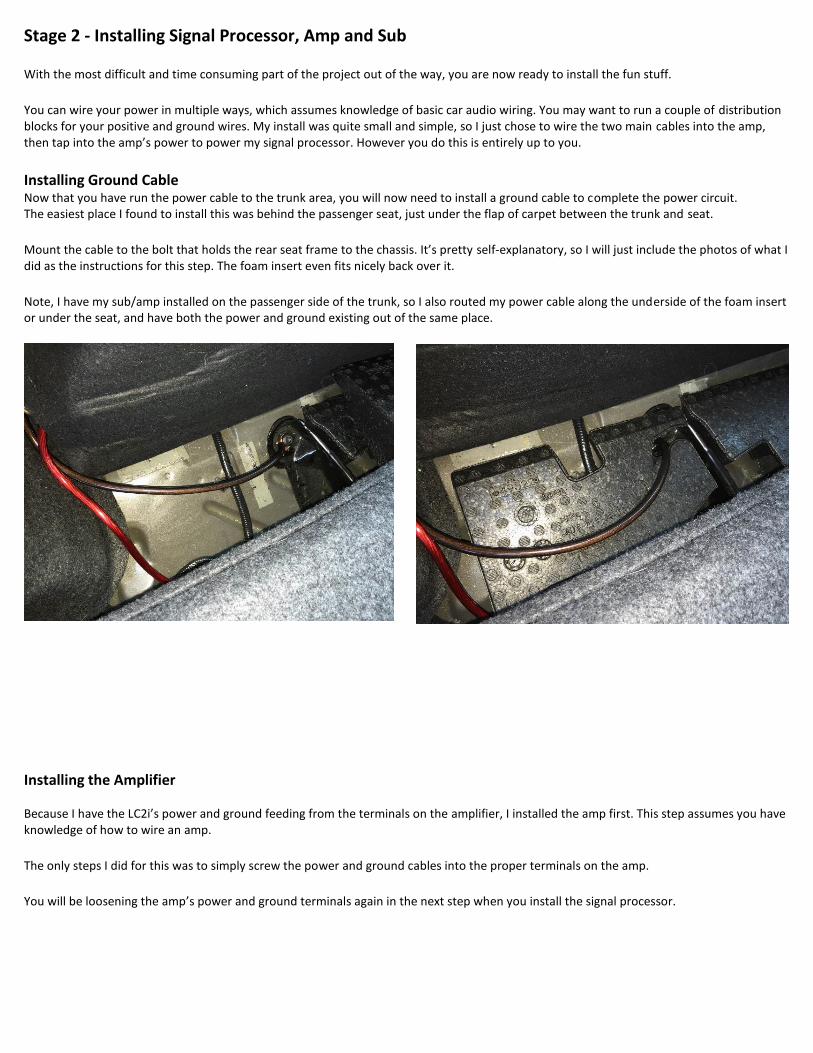
1. Remove trim panels Starting at the front of the car, you will need to pull out the various plastic trim pieces so you can run the cable under the carpet. Remove panels in the order of: 1 - front door sill 2 - front kick plate 3 - rear door sill / panel next to the rear seat 4 - B-Pillar plastic (not all the way off, just out enough to get under/behind it)
Be very careful when removing plastic trim panels. They are all held in with plastic clips that snap into each other. Forcing any the wrong way will snap these clips off and the trim will never sit correctly again or will always be loose. I can’t stress this enough. Do not force panels off. If they aren’t coming loose, gently work at them or pry it up enough to see under/behind it to see where it is stuck or binding and gently work it free from there. 2. Once the panels are all removed, simply run the cable behind all trim/parts and under the carpet up under the rear seat, and exit into the trunk. Pull all the remaining slack into the trunk, leaving enough play in the cable throughout so that you can lay the carpet back over it and pop all the trim panels back into place.
Photo on the lower right is under the driver’s side door sill.
Photo on the upper right is under the rear passenger seat. 3. Once your cable is fully run, take care when popping trim panels back in place in the reverse order of removal. They fit together like a big puzzle.
If you purchased the optional gain adjustment controller, don’t put your trim back on yet, and go to the next step.
Stage 1.5 - (Optional) Installing Signal Processor gain adjustment controller
Before putting your trim panels back on, take a moment to run the gain adjustment controller wire. The most likely scenario will be that it will go from the trunk (plugged into the signal processor), run back up to the front of the car alongside your power cable, and then exit out under your dash somewhere. I did not yet run mine, so I can’t tell you the best place to mount it. Mounting is also a purely personal preference. Once you’ve run this controller, and mounted the knob, you can reinstall your trim panels.
Stage 2 - Installing Signal Processor, Amp and Sub
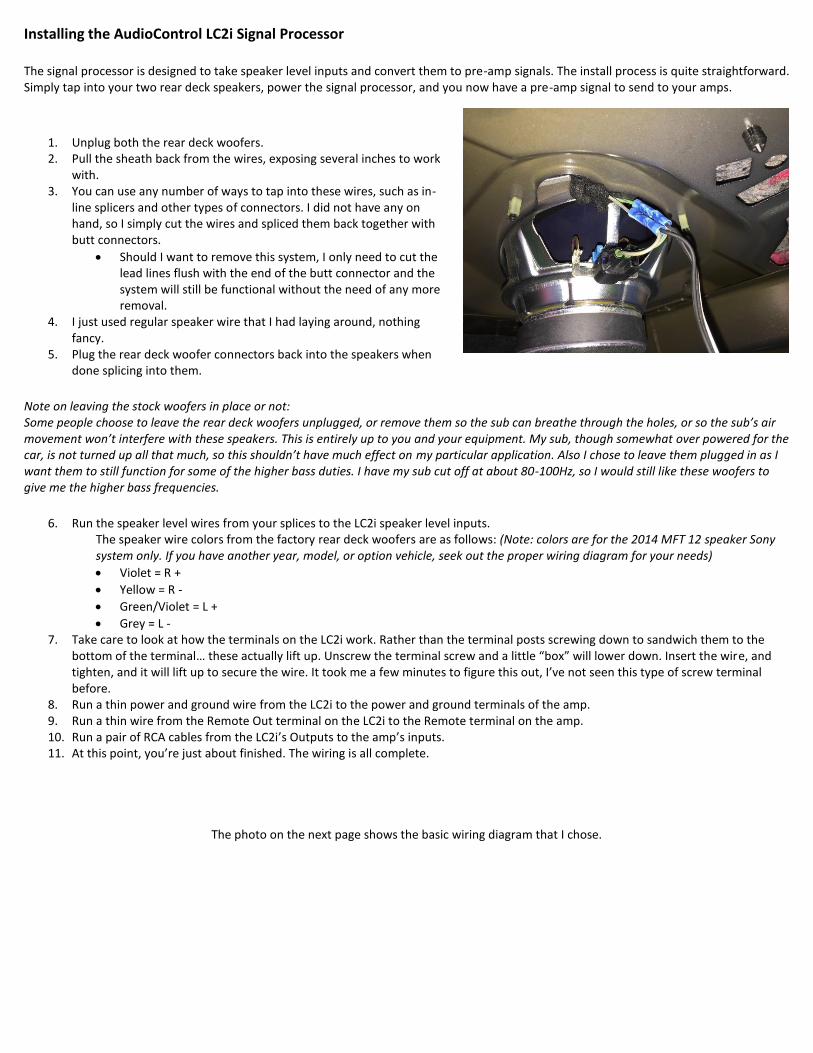
With the most difficult and time consuming part of the project out of the way, you are now ready to install the fun stuff. You can wire your power in multiple ways, which assumes knowledge of basic car audio wiring. You may want to run a couple of distribution blocks for your positive and ground wires. My install was quite small and simple, so I just chose to wire the two main cables into the amp, then tap into the amp’s power to power my signal processor. However you do this is entirely up to you. Installing Ground Cable Now that you have run the power cable to the trunk area, you will now need to install a ground cable to complete the power circuit. The easiest place I found to install this was behind the passenger seat, just under the flap of carpet between the trunk and seat. Mount the cable to the bolt that holds the rear seat frame to the chassis. It’s pretty self-explanatory, so I will just include the photos of what I did as the instructions for this step. The foam insert even fits nicely back over it. Note, I have my sub/amp installed on the passenger side of the trunk, so I also routed my power cable along the underside of the foam insert or under the seat, and have both the power and ground existing out of the same place.
Installing the Amplifier
Because I have the LC2i’s power and ground feeding from the terminals on the amplifier, I installed the amp first. This step assumes you have knowledge of how to wire an amp. The only steps I did for this was to simply screw the power and ground cables into the proper terminals on the amp. You will be loosening the amp’s power and ground terminals again in the next step when you install the signal processor.
Installing the AudioControl LC2i Signal Processor The signal processor is designed to take speaker level inputs and convert them to pre-amp signals. The install process is quite straightforward. Simply tap into your two rear deck speakers, power the signal processor, and you now have a pre-amp signal to send to your amps.
1. Unplug both the rear deck woofers. 2. Pull the sheath back from the wires, exposing several inches to work
with. 3. You can use any number of ways to tap into these wires, such as in-
line splicers and other types of connectors. I did not have any on hand, so I simply cut the wires and spliced them back together with butt connectors.
Should I want to remove this system, I only need to cut the lead lines flush with the end of the butt connector and the system will still be functional without the need of any more removal.
4. I just used regular speaker wire that I had laying around, nothing fancy.
5. Plug the rear deck woofer connectors back into the speakers when done splicing into them.
Note on leaving the stock woofers in place or not: Some people choose to leave the rear deck woofers unplugged, or remove them so the sub can breathe through the holes, or so the sub’s air movement won’t interfere with these speakers. This is entirely up to you and your equipment. My sub, though somewhat over powered for the car, is not turned up all that much, so this shouldn’t have much effect on my particular application. Also I chose to leave them plugged in as I want them to still function for some of the higher bass duties. I have my sub cut off at about 80-100Hz, so I would still like these woofers to give me the higher bass frequencies.
6. Run the speaker level wires from your splices to the LC2i speaker level inputs. The speaker wire colors from the factory rear deck woofers are as follows: (Note: colors are for the 2014 MFT 12 speaker Sony system only. If you have another year, model, or option vehicle, seek out the proper wiring diagram for your needs) Violet = R +
Yellow = R -
Green/Violet = L +
Grey = L - 7. Take care to look at how the terminals on the LC2i work. Rather than the terminal posts screwing down to sandwich them to the
bottom of the terminal… these actually lift up. Unscrew the terminal screw and a little “box” will lower down. Insert the wire, and tighten, and it will lift up to secure the wire. It took me a few minutes to figure this out, I’ve not seen this type of screw terminal before.
8. Run a thin power and ground wire from the LC2i to the power and ground terminals of the amp. 9. Run a thin wire from the Remote Out terminal on the LC2i to the Remote terminal on the amp. 10. Run a pair of RCA cables from the LC2i’s Outputs to the amp’s inputs. 11. At this point, you’re just about finished. The wiring is all complete.
The photo on the next page shows the basic wiring diagram that I chose.
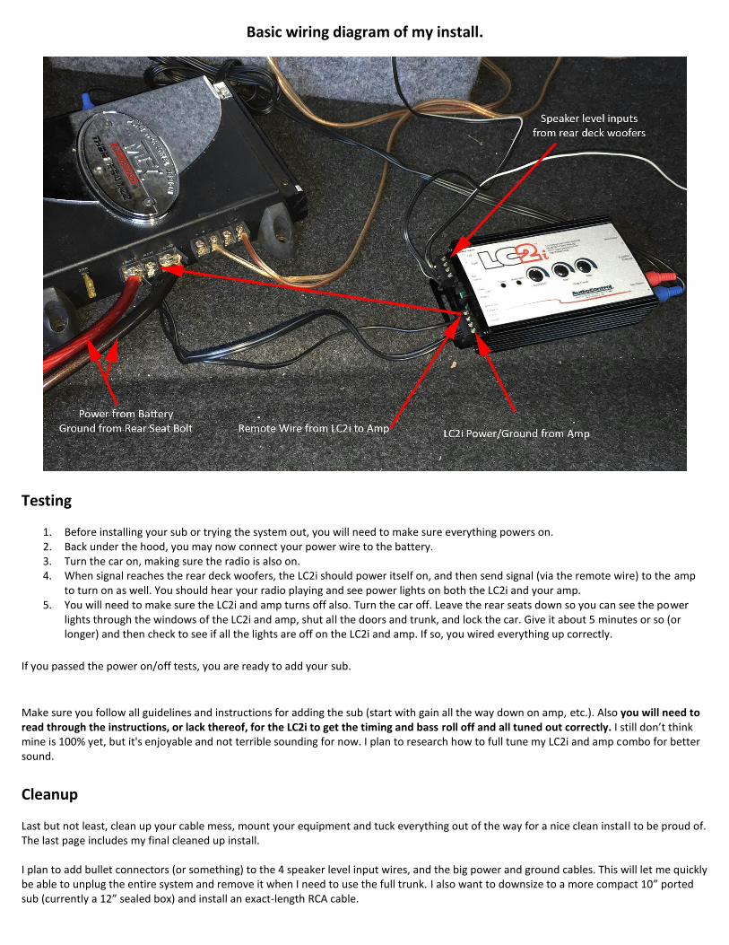
Basic wiring diagram of my install.
Testing
1. Before installing your sub or trying the system out, you will need to make sure everything powers on. 2. Back under the hood, you may now connect your power wire to the battery. 3. Turn the car on, making sure the radio is also on. 4. When signal reaches the rear deck woofers, the LC2i should power itself on, and then send signal (via the remote wire) to the amp
to turn on as well. You should hear your radio playing and see power lights on both the LC2i and your amp. 5. You will need to make sure the LC2i and amp turns off also. Turn the car off. Leave the rear seats down so you can see the power
lights through the windows of the LC2i and amp, shut all the doors and trunk, and lock the car. Give it about 5 minutes or so (or longer) and then check to see if all the lights are off on the LC2i and amp. If so, you wired everything up correctly.
If you passed the power on/off tests, you are ready to add your sub.
Make sure you follow all guidelines and instructions for adding the sub (start with gain all the way down on amp, etc.). Also you will need to read through the instructions, or lack thereof, for the LC2i to get the timing and bass roll off and all tuned out correctly. I still don’t think mine is 100% yet, but it's enjoyable and not terrible sounding for now. I plan to research how to full tune my LC2i and amp combo for better sound.
Cleanup
Last but not least, clean up your cable mess, mount your equipment and tuck everything out of the way for a nice clean install to be proud of. The last page includes my final cleaned up install. I plan to add bullet connectors (or something) to the 4 speaker level input wires, and the big power and ground cables. This will let me quickly be able to unplug the entire system and remove it when I need to use the full trunk. I also want to downsize to a more compact 10” ported sub (currently a 12” sealed box) and install an exact-length RCA cable.
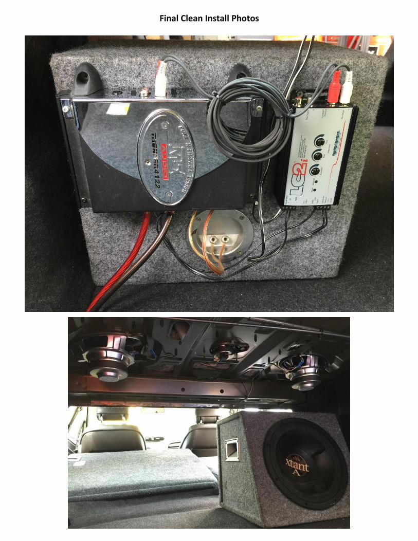
Final Clean Install Photos
Recommended