
MODEL STC
OPERATOR’S MANUAL
THIS MANUAL CONTAINS THE OPERATINGINSTRUCTIONS AND SAFETY INFORMA-TION FOR YOUR SCAG MOWER. READINGTHIS MANUAL CAN PROVIDE YOU WITHASSISTANCE IN MAINTENANCE AND AD-JUSTMENT PROCEDURES TO KEEP YOURMOWER PERFORMING TO MAXIMUM EFFI-CIENCY. THE SPECIFIC MODELS THAT THISBOOK COVERS ARE CONTAINED ON THEINSIDE COVER. BEFORE OPERATING YOURMACHINE, PLEASE READ ALL THE INFOR-MATION ENCLOSED.
PART NO. 03194PRINTED 7/2006
PRINTED IN USA
© 2006SCAG POWER EQUIPMENTDIVISION OF METALCRAFT OF MAYVILLE, INC.

FAILURE TO FOLLOW SAFE OPERATING PRACTICES MAY RESULT IN SERIOUS INJURY.
REMEMBER - YOUR MOWER IS ONLY AS SAFE AS THE OPERATOR!Hazard control and accident prevention are dependent upon the awareness,concern, prudence, and proper training of the personnel involved in theoperation, transport, maintenance, and storage of the equipment.
This manual covers the operating instructions and illustrated parts list for:
STC48V-19KAI with a serial number of C6000001 to C6099999STC48V-23CV with a serial number of C6200001 to C6299999STC52V-23KA with a serial number of C6300001 to C6399999STC52V-24HN with a serial number of C6400001 to C6499999SMTC-48V with a serial number of C7000001 to C7099999SMWC-52V with a serial number of C7100001 to C7199999
Always use the entire serial number listed on the serial numbertag when referring to this product.
WARNING:
* Keep all shields in place, especially the grass discharge chute.* Before performing any maintenance or service, stop the machine and remove the spark plug wire and ignition key.* If a mechanism becomes clogged, stop the engine before cleaning.* Keep hands, feet and clothing away from power-driven parts.* Read this manual completely as well as other manuals that came with your mower.* Keep others off the tractor (only one person at a time)* DO NOT operate on steep slopes. To check a slope, attempt to back up it (with the cutter deck down). If the machine can back up the slope without the wheels slipping, reduce speed and use extreme caution. Under no circumstances should the machine be operated on slopes greater than 15 degrees. ALWAYS FOLLOW OSHA APPROVED OPERATION.* DO NOT mow on wet grass. Wet grass reduces traction and steering control.

I
TABLE OF CONTENTS
4.14 Towing ................................................................................................................................. 194.15 Adjusting the Steering Levers ............................................................................................... 19
SUBJECT PAGE
Section 1 - General Information1.1 Introduction .............................................................................................................................11.2 Directional Reference .............................................................................................................11.3 Servicing the Engine and Drive Train Components ................................................................11.3 Symbols ............................................................................................................................... 2-3
Section 2 - Safety Information2.1 Introduction .............................................................................................................................42.2 Signal Words ...........................................................................................................................42.3 Before Operation Considerations ...........................................................................................42.4 Operation Considerations ........................................................................................................52.5 Roll Over Protection System ..................................................................................................72.6 Maintenance Considerations ...................................................................................................92.7 Safety and Instructional Decals ............................................................................................ 10
Section 3 - Specifications ...................................................................................................... 11-1
Section 4 - Operating Instructions4.1 Controls and Instrument Identification ................................................................................. 134.2 Safety Interlock System ....................................................................................................... 144.3 Initial Run-In Procedures ..................................................................................................... 154.4 Starting the Engine ............................................................................................................... 154.5 Ground Travel and Steering ................................................................................................. 154.6 Engaging the Deck Drive ...................................................................................................... 164.7 Hillside Operation ................................................................................................................. 174-8 Parking the Mower ............................................................................................................... 174.9 After Operation .................................................................................................................... 174.10 Removing Clogged Material ................................................................................................. 184.11 Moving Mower with Engine Stopped ................................................................................... 184.12 Recommendations for Mowing ............................................................................................ 184.13 Adjusting Cutting Height ....................................................................................................... 18
Section 5 - Troubleshooting Cutting Conditions............................................................... 20-22

II
TABLE OF CONTENTS (CONT'D)SUBJECT PAGE
Section 6 - Adjustments6.1 Parking Brake Adjustment .................................................................................................... 236.2 Travel Adjustments ............................................................................................................... 246.3 Throttle Control and Choke Adjustments .............................................................................. 256.4 Belt Adjustment .................................................................................................................... 256.5 Belt Alignment ...................................................................................................................... 256.6 Cutter Deck Adjustments ..................................................................................................... 26
Section 7 - Maintenance7.1 Maintenance Chart ............................................................................................................... 297.2 Lubrication Fitting Points ...................................................................................................... 307.3 Hydraulic System .................................................................................................................. 327.4 Engine Oil .............................................................................................................................337.5 Engine Fuel System .............................................................................................................. 347.6 Engine Air Cleaner ................................................................................................................ 347.7 Battery .................................................................................................................................. 357.8 Drive Belts ............................................................................................................................367.9 Cutter Blades ........................................................................................................................ 367.10 Tires ...................................................................................................................................... 377.11 Body, Deck and Upholstery .................................................................................................. 37
Section 8 - Replacement PartsSTC48V, STC52V Cutter Deck ............................................................................................... 38-39Cutter Deck Controls ................................................................................................................ 40-41Sheet Metal Components .......................................................................................................... 42-43STC Roll-Over Protection System ........................................................................................... 44-45Drive System Components ....................................................................................................... 46-47Engine and Attaching Parts - Kawasaki & Kohler .................................................................. 48-49Engine and Attaching Parts - Honda ........................................................................................ 50-51Steering Components ................................................................................................................ 52-53Brake Components .................................................................................................................... 54-55Fuel and Hydraulic System ....................................................................................................... 56-57Electrical System ....................................................................................................................... 58-59Hydraulic Pump (BDP-10A) ..................................................................................................... 60-61Replacement Decals .................................................................................................................. 62-63Electrical Schematic ....................................................................................................................... 64Warranty Statement ............................................................................ Following Illustrated Parts List
1
Scag approved attachments and accessories:GC-STC-V (p/n 9057)GC-STC-CSV (p/n 9061)Mulch Plate (p/n 9286, 9287)Hurricane Mulch (p/n 9283, 9284)STC Hitch (p/n 9241)STC - Lights (p/n 9274)Tiger Striper (p/n 9269)GC-4D (p/n 9054)GC-F4 (p/n 9055)Soft Ride Seat (p/n 9291)Suspension Seat (p/n/ 9292)Blade Buddy (p/n 9212)
GENERAL INFORMATION1.1 INTRODUCTION
Your mower was built to the highest standards in the industry.However, the prolonged life and maximum efficiency ofyour mower depends on you following the operating,maintenance and adjustment instructions in this manual.
If additional information or service is needed, contact yourScag Power Equipment Dealer.
We encourage you to contact your dealer for repairs. AllScag dealers are informed of the latest methods to servicethis equipment and provide prompt and efficient service inthe field or at their service shop. They carry a full line ofScag service parts.
THE REPLACEMENT OF ANY PART ON THISPRODUCT BY OTHER THAN THEMANUFACTURER'S AUTHORIZEDREPLACEMENT PART MAY ADVERSELYAFFECT THE PERFORMANCE, DURABILITY ORSAFETY OF THIS PRODUCT.
USE OF OTHER THAN ORIGINAL SCAGREPLACEMENT PARTS WILL VOID THEWARRANTY.
For pictorial clarity, some illustrations and figuresin this manual may show shields, guards or platesopen or removed. Under no circumstances shouldyour mower be operated without these devices inplace.
All information is based upon product informationavailable at the time of approval for printing. ScagPower Equipment reserves the right to make changesat any time without notice and without incurring anyobligation.
1.2 DIRECTION REFERENCE
The “Right” and “Left”, “Front” and “Rear” of the machineare referenced from the operator’s right and left whenseated in the normal operating position and facing theforward travel direction.
1.3 SERVICING THE ENGINE AND DRIVE TRAIN COMPONENTS
The detail servicing and repair of the engine, hydraulic pumpsand gearboxes are not covered in this manual; only routinemaintenance and general service instructions are provided.For service of these components during the limited warrantyperiod, it is important to contact your Scag dealer or find alocal authorized servicing agent of the componentmanufacturer. Any unauthorized work done on thesecomponents during the warranty period may void yourwarranty.
Section 1
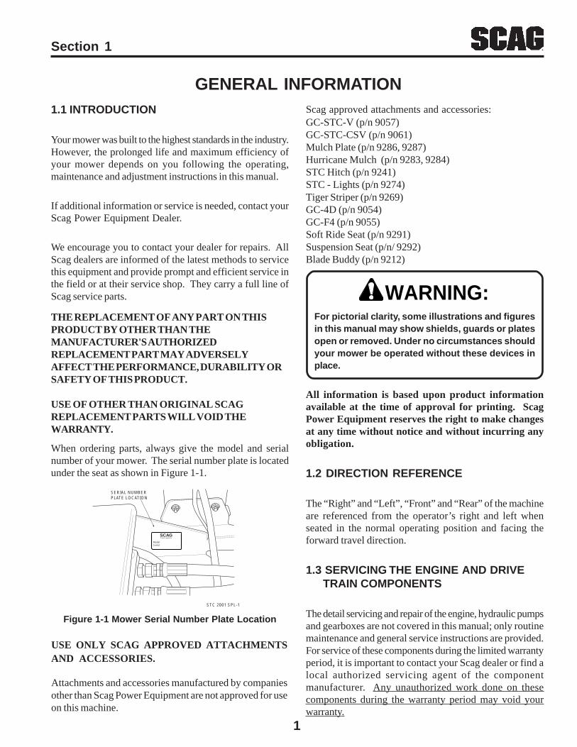
When ordering parts, always give the model and serialnumber of your mower. The serial number plate is locatedunder the seat as shown in Figure 1-1.
Figure 1-1 Mower Serial Number Plate Location
ModelSerial
SCAGPower Equipment
STC 2001 SPL-1
SERIAL NUMBERPLATE LOCATION
WARNING:
USE ONLY SCAG APPROVED ATTACHMENTSAND ACCESSORIES.
Attachments and accessories manufactured by companiesother than Scag Power Equipment are not approved for useon this machine.
2
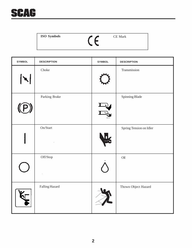
CE Mark
TransmissionChoke
On/Start Spring Tension on Idler
OilOff/Stop
SYMBOL DESCRIPTIONSYMBOL DESCRIPTION
ISO Symbols
Spinning Blade
48071S
Parking Brake
WARNINGFALLING HAZARD
USE ONLY SCAG APPROVEDRIDING ATTACHMENTS
SEE OPERATOR'S MANUAL 481109
Falling Hazard Thown Object Hazard
3
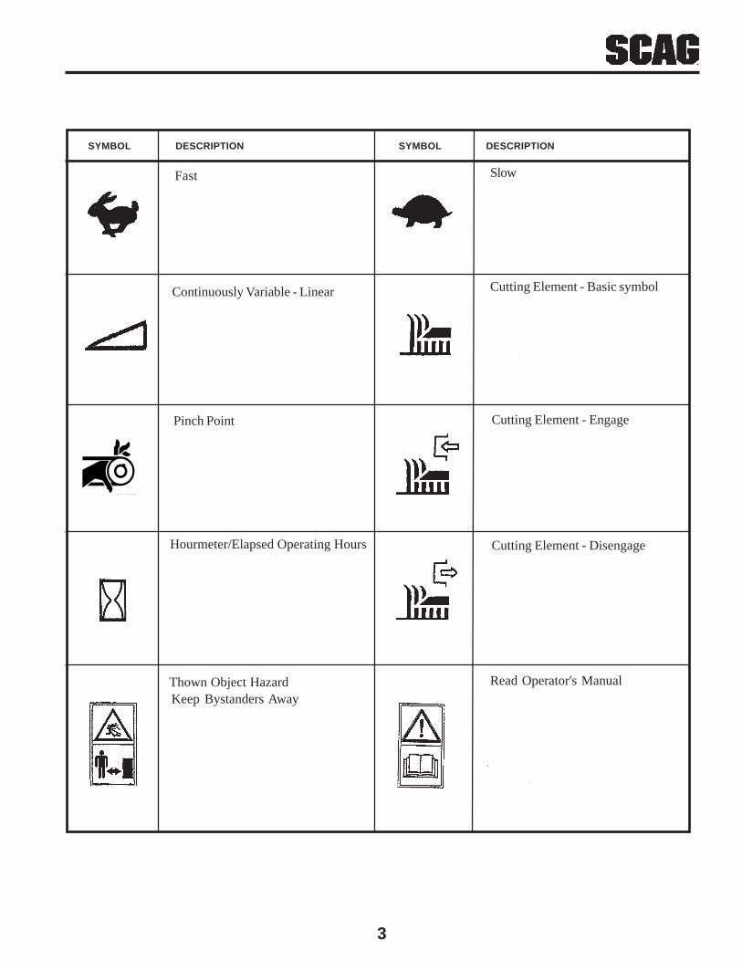
SlowFast
Cutting Element - Engage
Cutting Element - Basic symbol
Cutting Element - Disengage
Continuously Variable - Linear
Read Operator's ManualKeep Bystanders Away
Pinch Point
481039S
SYMBOL DESCRIPTION SYMBOL DESCRIPTION
Hourmeter/Elapsed Operating Hours
Thown Object Hazard

4
SAFETY INFORMATION2.1 INTRODUCTION
Your mower is only as safe as the operator.Carelessness or operator error may result in seriousbodily injury or death. Hazard control and accidentprevention are dependent upon the awareness, concern,prudence, and proper training of the personnel involved inthe operation, transport, maintenance and storage of theequipment. Make sure every operator is properly trainedand thoroughly familiar with all of the controls beforeoperating the mower. The owner/user can prevent and isresponsible for accidents or injuries occuring tothemselves, other people or property.
READ THIS OPERATOR’S MANUAL BEFOREATTEMPTING TO START YOUR MOWER.
A replacement manual is available from your authorizedScag Service Dealer or by contacting Scag PowerEquipment, Service Department at P.O. Box 152,Mayville, WI 53050 or via the Internet atwww.scag.com. The manual for your machine can bedownloaded by using the model and serial number or usethe contact form to make your request. Please indicatethe complete model and serial number of your Scagproduct when requesting replacement manuals.
2.2 SIGNAL WORDS
This symbol means “Attention! Become Alert! YourSafety is Involved!" The symbol is used with thefollowing signal words to attract your attention to safetymessages found on the decals on the machine andthroughout this manual. The message that follows thesymbol contains important information about safety. Toavoid injury and possible death, carefully read themessage! Be sure to fully understand the causes ofpossible injury or death.
Signal Word:
It is a distinctive word found on the safety decals on themachine and throughout this manual that alerts theviewer to the existence and relative degree of thehazard.
The signal word “WARNING” denotes that a hazardexists on or near the machine that can result in injury ordeath if proper precautions are not taken.
The signal word “DANGER” denotes that an extremelyhazardous situation exists on or near the machine thatcould result in high probability of death or irrepairableinjury if proper precautions are not taken.
CAUTION:The signal word “CAUTION” is a reminder of safetypractices on or near the machine that could result inpersonal injury if proper precautions are not taken.
Your safety and the safety of others depends significantlyupon your knowledge and understanding of all correctoperating practices and procedures of this machine.
2.3 BEFORE OPERATION CONSIDERATIONS
1. NEVER allow children to operate this riding mower.Do not allow adults to operate this machine withoutproper instructions.
2. DO NOT mow when children and/or others arepresent. Keep children out of the mowing area andin the watchful care of a responsible adult other thanthe operator. Be alert and turn machine off if a childenters the area.
3. DO NOT allow children to ride on or play on themachine, it is not a toy.
4. Clear the area to be mowed of objects that could bepicked up and thrown by the cutter blades.
5. DO NOT carry passengers.
6. DO NOT operate the machine under the influence ofalcohol or drugs.
WARNING:
Section 2
5
Section 2
9. Keep the machine and attachments in good operatingcondition. Keep all shields and safety devices inplace. If a shield, safety device or decal is defectiveor damaged, repair or replace it before operating themachine.
This machine is equipped with an interlock systemintended to protect the operator and others frominjury. This is accomplished by preventing theengine from starting unless the deck drive isdisengaged, the parking brake is on, the steeringcontrol levers are in the neutral position and theoperator is in the seat. The system shuts off theengine if the operator leaves the seat with the deckdrive engaged and/or the steering control leversare not in the neutral postion and the parking brakeis not engaged. Never operate equipment withthe interlock system disconnected ormalfunctioning.
10. Be sure the interlock switches are functioningcorrectly.
11. Fuel is flammable; handle it with care. Fill the fueltank outdoors. Never fill it indoors. Use a funnel orspout to prevent spillage. Clean up any spillagebefore starting the engine.
12. DO NOT add fuel to a running or hot engine. Allowthe engine to cool for several minutes before addingfuel. Never fuel indoors or enclosed trailers.
13. Keep flammable objects (cigarettes, matches, etc.),open flames and sparks away from the fuel tank andfuel container. Use only approved containers.
14. Equipment must comply with the latest requirementsper SAE J137 and/or ANSI/ASAE S279 when drivenon public roads.
If the mower is driven on public roads, it mustcomply with state and local ordinances as well asSAE J137 and/or ANSI / ASAE S279 requirements.Contact your local authorities for regulations andequipment requirements.
15. DO NOT operate without the side discharge chuteinstalled and in the down position or with an optionalgrass catcher or mulch plate completely installed.
16. Check the blade mounting bolts at frequent intervalsfor proper tightness.
17. Make sure all hydraulic fluid connections are tight andall hydraulic hoses and lines are in good conditionbefore starting the machine.
2.4 OPERATION CONSIDERATIONS
1. Know the function of all controls and how to stopquickly.
DO NOT operate on steep slopes. To check aslope, attempt to back up it (with the cutter deckdown). If the machine can back up the slope withoutthe wheels slipping, reduce speed and use extremecaution. Under no circumstances should themachine be operated on slopes greater than 15degrees.ALWAYS FOLLOW OSHA APPROVEDOPERATION.
this material to them.
8. DO NOT wear loose fitting clothing. Looseclothing, jewelry or long hair could get tangled inmoving parts. Do not operate the machine wearingshorts; always wear adequate protective clothingincluding long pants. Wearing safety glasses, safetyshoes and a helmet is advisable and is required bysome local ordinances and insurance regulations.
Always wear hearing protection. Operating thismachine over prolonged periods of time cancause loss of hearing.
7. If the operator(s) or mechanic(s) cannot read Englishor Spanish, it is the owner's responsibility to explain
WARNING:
-NOTE-
WARNING:
WARNING:
6
Section 2
2.4 OPERATION CONSIDERATIONS(CONT'D)
2. Reduce speed and exercise extreme caution on slopesand in sharp turns to prevent tipping or loss ofcontrol. Be especially cautious when changingdirections on slopes.
3. To prevent tipping or loss of control, start and stopsmoothly, avoid unnecessary turns and travel at reducedspeed.
4. When using any attachment, never direct the dischargeof material toward bystanders or allow anyone nearthe machine while in operation.
5. Before attempting to start the engine, with the operatorin the seat, disengage power to the cutter deck, placethe steering control levers in the neutral position andengage the parking brake.
6. If the mower discharge ever plugs, shut off the engine,remove the ignition key, and wait for all movement tostop before removing the obstruction.
DO NOT use your hand to dislodge the cloggeddischarge chute. Use a stick or other device toremove clogged material after the engine hasstopped running and the blades have stoppedturning.
7. Be alert for holes, rocks, roots and other hidden hazardsin the terrain. Keep away from any dropoff. Bewareof overhead obstructions (low limbs, etc.), undergroundobstacles (sprinklers, pipes, tree roots, etc.). Cautiouslyenter a new area. Be alert for hidden hazards.
8. Disengage power to cutter deck before backing up. Donot mow in reverse unless absolutely necessary andthen only after observation of the entire area behindthe mower. If you must mow in reverse, maintain aconstant lookout to the rear of the machine and mowslowly.
9. DO NOT turn sharply. Use care when backing up.
10. Disengage power to cutter deck before crossing roads,walks or gravel drives.
11. Mow only in daylight or good artificial light.
12. NEVER raise the deck with the blades engaged.
13. Take all possible precautions when leaving the machineunattended, such as disengaging the mower, loweringthe attachments, setting the parking brake, stopping theengine, and removing the key.
14. Disengage power to the attachments when transportingor when not in use.
15. The machine and attachments should be stopped andinspected for damage after striking a foreign object,and damage should be repaired before restarting andoperating the machine.
DO NOT touch the engine or the muffler whilethe engine is running or immediately afterstopping. These areas may be hot enough tocause a burn.
DO NOT run the engine inside a building or aconfined area without proper ventilation.Exhaust fumes are hazardous and contain carbonmonoxide which can cause brain injury and death.
16. Keep hands and feet away from cutter blades andmoving parts. Contact can injure.
17. Use care when loading or unloading the machine ontoa trailer or truck.
18. Use care when approaching blind corners, shrubs, trees,or other objects that may obscure vision.
19. NEVER leave the machine running unattended.
WARNING:
CAUTION:
7
2.5 ROLL OVER PROTECTION SYSTEM
WARNING:Keep the roll bar in the raised and lockedposition and the seat belt securely fastenedduring operation. Failure to do so couldcause serious injury or loss of life.
This mower has been designed for good traction andstability under normal mowing conditions. However,caution must be used when traveling on slopes, especiallywhen the grass is wet. Do not mow on wet grass. Wetgrass reduces traction and steering control.
Any or all parts of the Roll-Over Protection System MUSTNOT be removed. Failure to adhere to this guideline couldresult in injury or death.
There is no roll-over protection when the roll bar isin the down position.
Lower the roll bar only when absolutelynecessary.
DO NOT wear the seat belt when the roll bar isin the down position.
ALWAYS wear seat belt when roll bar is in theup position.
Operate the machine smoothly, no sudden turns,starts or stops.
Raise the roll bar as soon as clearance permits.
Check the area carefully before mowing for properoverhead clearance (i.e. branches, doorways, etc.).
DO NOT contact any overhead object with the rollbar.
WARNING:
Section 2
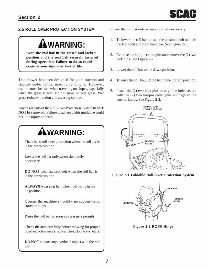
Figure 2-1 Foldable Roll-Over Protection System
Figure 2-2 ROPS Hinge
TENSIONKNOB
HAIR PIN
LOCK PIN
UPRIGHT ANDLOCKED POSITION
TENSIONKNOBS
Lower the roll bar only when absolutely necessary.
1. To lower the roll bar, loosen the tension knob on boththe left hand and right hand bar. See Figure 2-1.
2. Remove the hairpin cotter pins and remove the (2) twolock pins. See Figure 2-2.
3. Lower the roll bar to the down position.
4. To raise the roll bar, lift the bar to the upright position.
5. Install the (2) two lock pins through the hole, securewith the (2) two hairpin cotter pins and tighten thetension knobs. See Figure 2-2.
8
Section 2
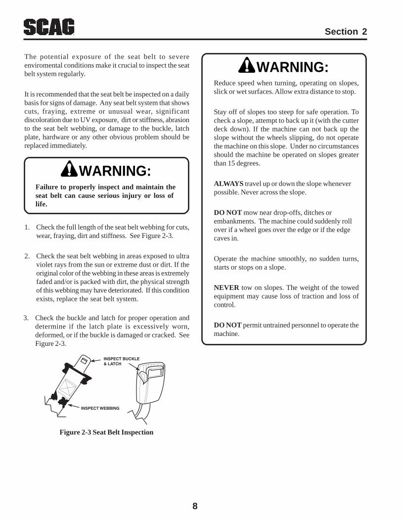
Figure 2-3 Seat Belt Inspection
The potential exposure of the seat belt to severeenviromental conditions make it crucial to inspect the seatbelt system regularly.
It is recommended that the seat belt be inspected on a dailybasis for signs of damage. Any seat belt system that showscuts, fraying, extreme or unusual wear, significantdiscoloration due to UV exposure, dirt or stiffness, abrasionto the seat belt webbing, or damage to the buckle, latchplate, hardware or any other obvious problem should bereplaced immediately.
1. Check the full length of the seat belt webbing for cuts,wear, fraying, dirt and stiffness. See Figure 2-3.
2. Check the seat belt webbing in areas exposed to ultraviolet rays from the sun or extreme dust or dirt. If theoriginal color of the webbing in these areas is extremelyfaded and/or is packed with dirt, the physical strengthof this webbing may have deteriorated. If this conditionexists, replace the seat belt system.
WARNING:Failure to properly inspect and maintain theseat belt can cause serious injury or loss oflife.
3. Check the buckle and latch for proper operation anddetermine if the latch plate is excessively worn,deformed, or if the buckle is damaged or cracked. SeeFigure 2-3.
WARNING:
INSPECT WEBBING
INSPECT BUCKLE& LATCH
Reduce speed when turning, operating on slopes,slick or wet surfaces. Allow extra distance to stop.
Stay off of slopes too steep for safe operation. Tocheck a slope, attempt to back up it (with the cutterdeck down). If the machine can not back up theslope without the wheels slipping, do not operatethe machine on this slope. Under no circumstancesshould the machine be operated on slopes greaterthan 15 degrees.
ALWAYS travel up or down the slope wheneverpossible. Never across the slope.
DO NOT mow near drop-offs, ditches orembankments. The machine could suddenly rollover if a wheel goes over the edge or if the edgecaves in.
Operate the machine smoothly, no sudden turns,starts or stops on a slope.
NEVER tow on slopes. The weight of the towedequipment may cause loss of traction and loss ofcontrol.
DO NOT permit untrained personnel to operate themachine.
9
2.6 MAINTENANCE CONSIDERATIONS & STORAGE
1. Never make adjustments to the machine with theengine running unless specifically instructed to do so.If the engine is running, keep hands, feet, andclothing away from moving parts.
2. Disengage drives, lower implement, set parkingbrake, stop engine and remove key or disconnectspark plug wire to prevent accidental starting of theengine when servicing or adjusting the machine.Wait for all movement to stop before adjusting,cleaning or repairing.
3. Disconnect battery or remove spark plug wire beforemaking any repairs. Disconnect the negativeterminal first and the positive last. Reconnect thepositive first and the negative last.
4. Keep all nuts, bolts and screws tight, to ensure themachine is in safe working condition. Check blademounting bolts frequently to be sure they are tight.
5. Do not change the engine governor settings oroverspeed the engine. See the engine operator'smanual for information on engine settings.
Section 2
11. Use jack stands to support components whenrequired.
12. Carefully release pressure from components withstored energy.
13. Let the engine cool before storing.
14. DO NOT store the machine near an open flame.
15. Shut off fuel while storing or transporting.
16. DO NOT store fuel near flames or drain indoors.
17. Charge batteries in an open well ventilated area,away from spark and flames. Unplug charger beforeconnecting or disconnecting from battery. Wearprotective clothing and use insulated tools.
6. To reduce fire hazard, keep the cutting units, drivesmuffler and engine free of grass, leaves, excessivegrease, oil and dirt.
7. Park the machine on level ground and engage theparking brake.
8. NEVER allow untrained personnel to service themachine.
9. Use care when checking blades. Wrap the blade(s)or wear gloves and use caution when servicingblades. Only replace blades. NEVER straighten orweld blades.
10. Keep all parts in good working condition. Replace allworn or damaged decals.
Hydraulic fluid is under high pressure. Keepbody and hands away from pinholes or nozzlesthat eject hydraulic fluid under high pressure.If you need service on your hydraulic system,please see your authorized Scag dealer. Ifhydraulic fluid is injected into the skin, it mustbe surgically removed within a few hours by adoctor or gangrene may result.
WARNING:
10
Section 2
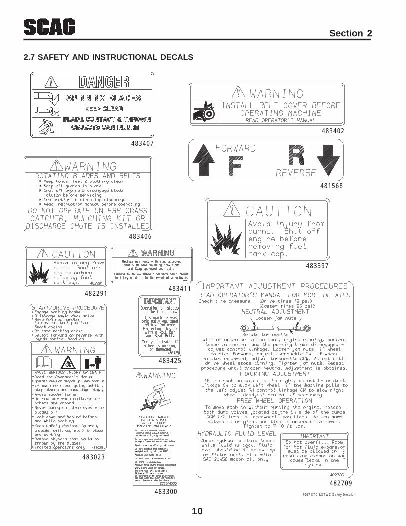
2.7 SAFETY AND INSTRUCTIONAL DECALS
483407
483402
481568
483397
483406
482709
2007 STC &STWC Safety Decals
483023
482291
483300
483411
483425
11
Section 3
SPECIFICATIONS3.1 ENGINEGeneral Type .............................................................................. Heavy Duty Industrial/Commercial GasolineBrand ......................................................................................... Kawasaki, KohlerHorsepower ............................................................................... 19 HP (Spec.#FH580V) (Scag Model STC48V-19KAI)
23 HP (Spec.# PS-75607) (Scag Model STC48V-23CV)23 HP (Spec.#FH680V-AS32) (Scag Model STC52V-23KA)24 HP (Spec. #GXV670TAF2) (Scag Model STC52V-24HN)Type 4 Cycle Gasoline, Twin Cylinder, Vertical Shaft
Cylinders .................................................................................... 2 with Cast Iron SleevesGovernor .................................................................................... Mechanical Type with Variable Speed Control Set At 3600 RPMIdle Speed .................................................................................. 1550 RPM - Kawasaki
1900 RPM - Kohler1350 RPM - Honda
Kawasaki Fuel Pump Group ...................................................... Mechanical Fuel Pump with In-Line Fuel Filter, Fixed Jet................................................................................................... Downdraft Carburetor.
Fuel ............................................................................................ Non-Leaded Gasoline with a Minimum Octane Rating of 87Oil Pump Group .......................................................................... Positive Displacement Gerotor™ Oil PumpStarter ......................................................................................... Electric Starting with Solenoid Shift StarterBelts: .......................................................................................... Kevlar cord. Self-adjusting, Self-tighteningPump Drive Belt ......................................................................... Scag Part Number - 483172
3.2 ELECTRICALBattery ....................................................................................... 12 VoltCharging System ........................................................................ AlternatorCharging Output ........................................................................ 12 Volt, 13 Amp - Kawasaki
12 Volt, 15 Amp - KohlerSystem Polarity .......................................................................... Negative GroundStarter ......................................................................................... 12 Volt Electric Ring Gear Type, Key and Solenoid Operated InterlockSwitches ..................................................................................... Seat, Neutral Control, Mower Engagement (BBC), Parking BrakeInstrument Panel ........................................................................ Key Switch, Throttle Lever, Manual Choke,
PTO Switch, Fuses and Safety Start moduleFuses ......................................................................................... Two (2) 20 Amp
3.3 TRACTORDrive System .............................................................................. Hydraulic Drive with Two Variable Displacement Pumps and Two
Cast-iron High Torque MotorsHydrostatic Pumps .................................................................... Two Hydro-Gear™ BDP 10A Pumps with Dump Valves for
movement without running the engineDrive Wheel Motors .................................................................. Two Hydro-Gear™ Cast-Iron High Torque MotorsSteering/Travel Control .............................................................. Twin Lever Fingertip Steering Control with Individual Control to
Each Wheel with Gas Spring DampersParking Brake ............................................................................. Lever Actuated Linkage to Brakes on Both Drive Wheel AxlesWheels: (2) Front Caster ...................................................................... 13 X 5.0-6 Flat free, w/tapered roller bearing pivots (2) Drive - (48"-52" Deck) ...................................................... 23 X 9.50 X 12 Four-Ply Pneumatic Tubeless, Radius EdgeFuel Tanks .................................................................................. Dual 4.5-Gallon Seamless Polyethylene Tanks with large opening and Fuel CapTire Pressure: Front Caster ........................................................................... Flat Free Drive ...................................................................................... 12 PSISeat ............................................................................................ Padded, Thick Cushion with Extra Spring Support
12
Section 3
3.3 TRACTOR (CONT'D)
Travel Speed: Forward ................................................................................. 0-10 MPH Reverse .................................................................................. 0-5 MPH
3.4 CUTTER DECK
Type: .......................................................................................... Floating, Adjustable, Anti-scalping, Hybrid Design CombinesOut-front and Belly-mount Designs
Construction: ............................................................................. Tri-plate deck construction, top of deck consists of three steel plates totaling nearly 1/2" of steel.,7-gauge (3/16") deck skirt.True Cutting Width: ................................................................... 48" (122.0 cm), 52" (132.0 cm)Cutting Height Adjustment: ....................................................... Foot Operated Lever Adjustment from Operator's Seat, 1.00" to
5.5" in 1/4"incrementsCutter Blades: ............................................................................. 197 Thick, Milled Edge, Wear Resistant Marbain™Blade Engagement: ................................................................... Electric Blade Engagement Clutch with Control Panel Switch
Connected to the Cutter Deck via through a Belt.Discharge Opening: ................................................................... Extra Wide Discharge Opening with Spring Loaded Discharge Chute and Turbo BaffleSpindles: .................................................................................... Heavy-duty 1-1/8" Top Dimension Spindle Shaft, Cast Housing,
Taper Roller Bearing, Low Maintenance with Top Access GreaseFitting and Grease Overfill Relief Poppet
Spindle Pulleys: .......................................................................... Split Steel with Easily Removed Taper HubsCutter Deck Belts: ...................................................................... B-section and Cogged Type with Kevlar Cord. Self-adjusting, Self-tighteningElectric Clutch Type ................................................................... Ogura Heavy Duty PTO Clutch Brake
3.6 HYDRAULIC SYSTEMHydraulic Oil Filter ..................................................................... 10 Micron Spin-on Element TypeHydraulic Reservoir ................................................................... Nylon; 2-1/2 Quart Capacity
3.7 PRODUCTIVITY
The following chart will aid you in determining how many acres your Scag mower will cut per day.
The chart is an estimate based on 8 hours per day cutting time at 6 MPH with a 20% allowance for overlap and turns.
Cutting Width: 48" 52"
Acres Per Day: 18.6 20.2
-NOTE-
The machine will travel at 10 mph fortransport purposes. For best cuttingperformance the forward travel speedshould be adjusted depending upon thecutting conditions.
13
Section 4
OPERATING INSTRUCTIONS
Do not attempt to operate this mower unless youhave read this manual. Learn the location andpurpose of all controls and instruments before youoperate this mower.
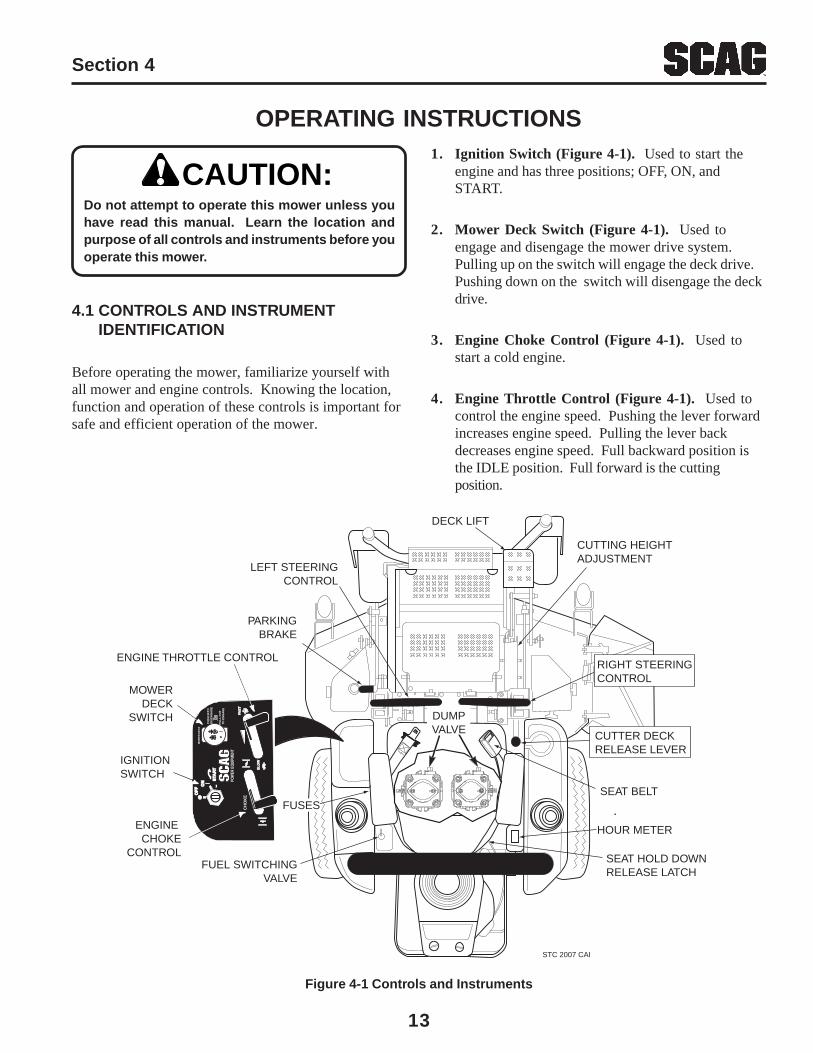
4.1 CONTROLS AND INSTRUMENT IDENTIFICATION
Before operating the mower, familiarize yourself withall mower and engine controls. Knowing the location,function and operation of these controls is important forsafe and efficient operation of the mower.
CAUTION:1. Ignition Switch (Figure 4-1). Used to start the
engine and has three positions; OFF, ON, andSTART.
2. Mower Deck Switch (Figure 4-1). Used toengage and disengage the mower drive system.Pulling up on the switch will engage the deck drive.Pushing down on the switch will disengage the deckdrive.
3. Engine Choke Control (Figure 4-1). Used tostart a cold engine.
4. Engine Throttle Control (Figure 4-1). Used tocontrol the engine speed. Pushing the lever forwardincreases engine speed. Pulling the lever backdecreases engine speed. Full backward position isthe IDLE position. Full forward is the cuttingposition.
Figure 4-1 Controls and Instruments
DECK LIFT
FUEL SWITCHINGVALVE
LEFT STEERINGCONTROL
PARKINGBRAKE
CUTTING HEIGHTADJUSTMENT
IGNITIONSWITCH
MOWERDECK
SWITCH
ENGINE THROTTLE CONTROL
ENGINE CHOKE
CONTROL
STC 2007 CAI
POW
ER E
QUIP
MEN
T
CH
OK
E
OF
FO
FF
ON
ON S
TAR
TS
TAR
T
FAS
TFA
ST
SL
OW
SL
OW
MO
WE
R D
EC
K
PU
SH
IN T
OD
ISE
NG
AG
E
PU
LL
OU
T
TO E
NG
AG
E
HOUR METER
FUSES
CUTTER DECKRELEASE LEVER
DUMPVALVE
SEAT BELT
RIGHT STEERINGCONTROL
SEAT HOLD DOWNRELEASE LATCH
14
Section 4
DUMP VALVECONTROL LEVERS
STC 2001 DVC
5. Hourmeter (Figure 4-1). Indicates the number ofhours the engine has been operated. It operateswhenever the ignition key switch is in the ONposition. Has preset maintenance reminders forengine and hydraulic system oil changes. Will startflashing scheduled maintenance 2 hours beforepreset time and continue flashing until 2 hours after.Automatically resets.
6. Fuse Holders (Figure 4-1). Two 20-amp fusesprotect the mower’s electrical system. To replacefuses, pull fuse out of the socket and install a newfuse.
7. Left Steering Control (Figure 4-1). Used tocontrol the mower's left wheel when travelingforward or reverse.
8. Right Steering Control (Figure 4-1). Used tocontrol the mower's right wheel when travelingforward or reverse.
9. Parking Brake Control (Figure 4-1). Used toengage and disengage the parking brakes. Pull thelever back to engage the parking brakes. Push thelever forward to disengage the parking brakes.
10. Fuel Switching Valve (Figure 4-1). Located onthe left side of the machine. Used to shut off fuelsupply to the engine and change fuel supply betweenthe fuel tanks. Rotate the valve counter clockwise tosupply fuel from the tank on the left side only.Rotate the valve clockwise to supply fuel from thetank on the right side only.
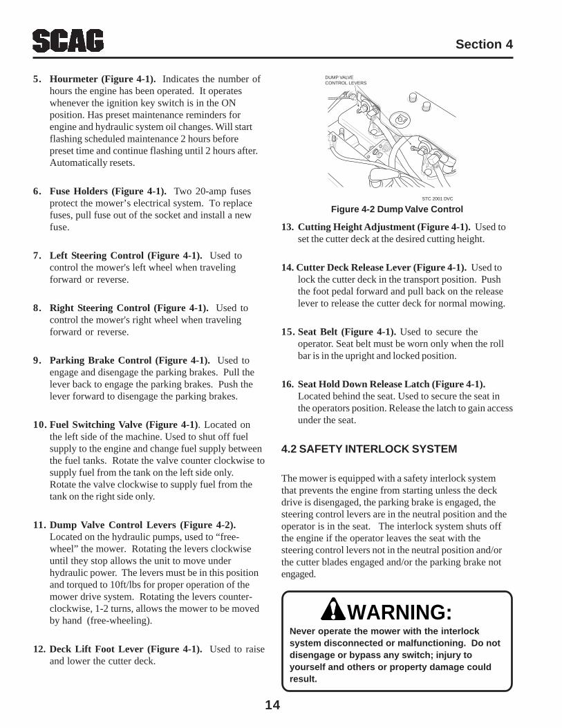
11. Dump Valve Control Levers (Figure 4-2).Located on the hydraulic pumps, used to “free-wheel” the mower. Rotating the levers clockwiseuntil they stop allows the unit to move underhydraulic power. The levers must be in this positionand torqued to 10ft/lbs for proper operation of themower drive system. Rotating the levers counter-clockwise, 1-2 turns, allows the mower to be movedby hand (free-wheeling).
12. Deck Lift Foot Lever (Figure 4-1). Used to raiseand lower the cutter deck.
Figure 4-2 Dump Valve Control
13. Cutting Height Adjustment (Figure 4-1). Used toset the cutter deck at the desired cutting height.
14. Cutter Deck Release Lever (Figure 4-1). Used tolock the cutter deck in the transport position. Pushthe foot pedal forward and pull back on the releaselever to release the cutter deck for normal mowing.
15. Seat Belt (Figure 4-1). Used to secure theoperator. Seat belt must be worn only when the rollbar is in the upright and locked position.
16. Seat Hold Down Release Latch (Figure 4-1).Located behind the seat. Used to secure the seat inthe operators position. Release the latch to gain accessunder the seat.
4.2 SAFETY INTERLOCK SYSTEM
The mower is equipped with a safety interlock systemthat prevents the engine from starting unless the deckdrive is disengaged, the parking brake is engaged, thesteering control levers are in the neutral position and theoperator is in the seat. The interlock system shuts offthe engine if the operator leaves the seat with thesteering control levers not in the neutral position and/orthe cutter blades engaged and/or the parking brake notengaged.
Never operate the mower with the interlocksystem disconnected or malfunctioning. Do notdisengage or bypass any switch; injury toyourself and others or property damage couldresult.
WARNING:
15
Section 4
4.3 INITIAL RUN-IN PROCEDURES (First Day of Use or Approximately 20 Hours)
1. Check all belts for proper alignment and wear at 2, 4and 8 hours.
2. Change the engine oil and oil filter after the first 20hours of operation. (See Section 7.4.)
3. Check hydraulic oil level in reservoir. (See Section7.3)
4. Check for loose hardware. Tighten as needed.
5. Check interlock system for proper operation. (SeeSection 4.2)
6. Check tire pressure. Adjust pressure if necessary.(See Section 7.10)
4.4 STARTING THE ENGINE
DO NOT USE STARTING FLUIDS. Use of startingfluids in the air intake system may be potentiallyexplosive or cause a “runaway” engine conditionthat could result in engine damage and/or personalinjury.
1. Be sure the fuel shutoff valve, located behind theoperator's seat by the left fuel tank, is completelyopen. (See Section 7.5)
2. Sit in the operator’s seat, fasten seat belt and placethe steering control levers in the neutral position.
3. Engage the parking brake.
4. If the engine is cold, choke the engine as needed.
5. Move the engine throttle control to about half enginespeed.
CAUTION:
6. Turn the ignition key to the START position andrelease the key as soon as the engine starts. Do nothold the key in the START position for more than 15seconds at a time. Allow at least 60 secondsbetween each cranking attempt to preventoverheating of the starter motor. Prolonged crankingcan damage the starter motor and shorten batterylife.
7. Allow engine to warm before operating the mower.
4.5 GROUND TRAVEL AND STEERING
-IMPORTANT-If you are not familiar with the operation of amachine with lever steering and/orhydrostatic transmissions, the steering andground speed operations should be learnedand practiced in an open area, away frombuildings, fences, or obstructions. Practiceuntil you are comfortable with the handling ofthe machine before attempting to mow. Learnthe operation on flat ground before operatingon slopes.
-IMPORTANT-Start practicing with a slow engine speed andslow forward travel. Learn to feather thesteering controls to obtain a smoothoperating action.
Forward Travel
To travel forward with the mower, disengage the parkingbrake, pull levers inward out of the neutral lock positionand slowly push the steering control levers forward anequal distance. The further the steering control leversare pushed forward the greater the forward speed willbe. To increase the speed, push the steering controllevers further forward and to decrease the speed, pull thesteering control levers back.
To stop the forward travel, pull the steering control leversback to the neutral position.
To steer the mower left while traveling forward, pull theleft steering lever back. The further the lever is pulledback, the quicker the mower will turn left.
16
Section 4
To steer the mower right while traveling forward, pull theright steering control lever back. The further the lever ispulled back, the quicker the mower will turn right.
-NOTE-Smooth operation of the steering levers willproduce smooth mower operation. Whilelearning the operation of the steeringcontrols, keep the travel speed low.
-IMPORTANT-Do not travel forward over a curb. Themower may hang up on the curb. Raise thedeck and travel backwards over the curb at a45 degree angle. (see section 4.1, item 12 forcutter deck raising instructions)
Reverse Travel
Disengage power to the mower before backing up.Do not mow in reverse unless absolutely necessaryand then only after observation of the entire areabehind the mower.
Before backing up, observe the rear for personsand obstructions. Clear the area before backingup. Possible injury or property damage could occur.
To travel in reverse, pull levers inward out of the neutrallock position and pull both handles back. Keep the travelspeed low while traveling in reverse.
-NOTE-The mower may not travel straight in reverse.Slight adjustments must be made using thesteering controls.
To steer left while traveling in reverse, allow the leftsteering control lever to move forward. The further thecontrol is allowed to move forward, the quicker themower will turn left.
To steer right while traveling in reverse, allow the rightsteering control lever to move forward. The further thecontrol is allowed to move forward, the quicker themower will turn right.
To stop the reverse travel, allow the steering controllevers to return to the neutral position. If the mower is tobe parked, place the handles in the neutral lock positionand engage the parking brake.
4.6 ENGAGING THE DECK DRIVE (CUTTER BLADES)
1. Set the throttle at about 3/4 speed. Do not attempt toengage the deck drive at high speed as this shortensthe electric clutch life — use only moderate enginespeed when engaging the deck drive.
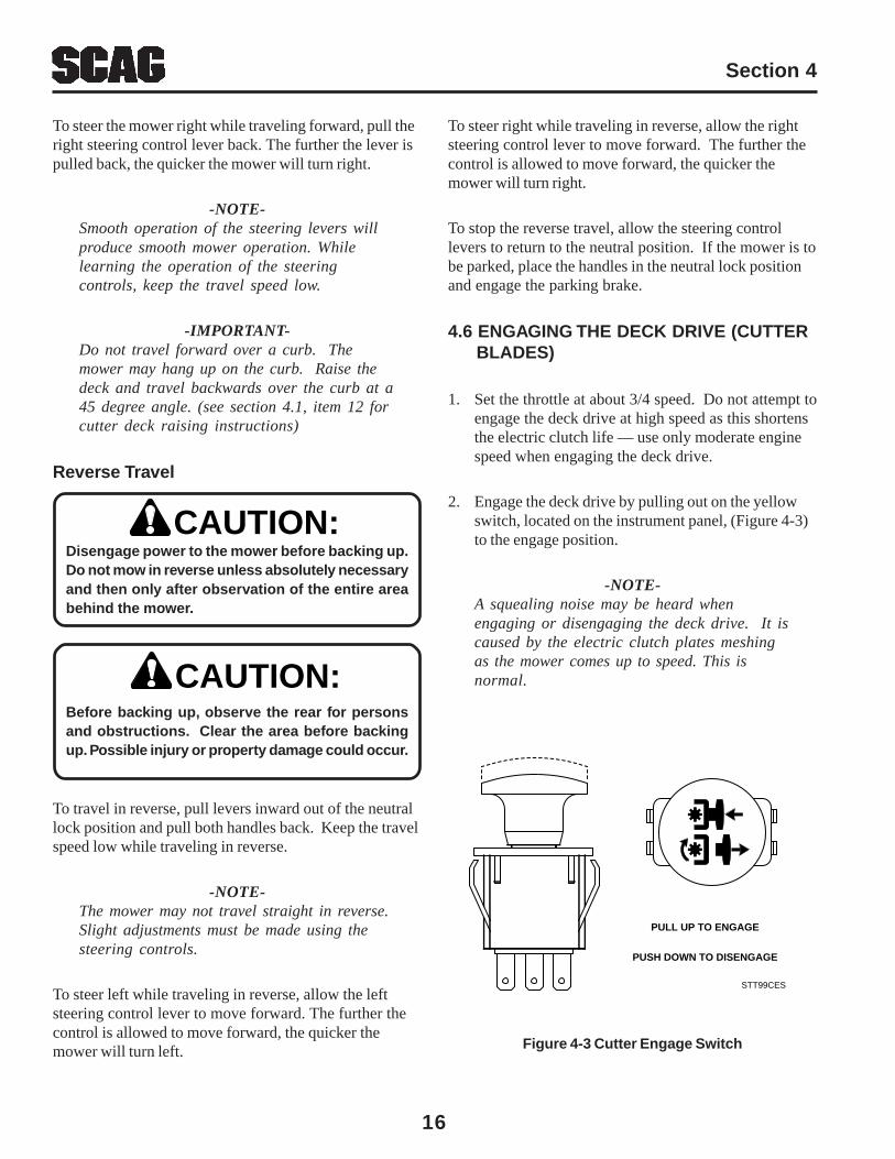
2. Engage the deck drive by pulling out on the yellowswitch, located on the instrument panel, (Figure 4-3)to the engage position.
-NOTE-A squealing noise may be heard whenengaging or disengaging the deck drive. It iscaused by the electric clutch plates meshingas the mower comes up to speed. This isnormal.
CAUTION:
CAUTION:
Figure 4-3 Cutter Engage Switch
STT99CES
PULL UP TO ENGAGE
PUSH DOWN TO DISENGAGE
17
Section 4
4.8 PARKING THE MOWER
1. Park the machine on a flat, level surface only. Do notpark the machine on an incline.
2. Place the steering control levers in the neutralposition.
3. Disengage the cutter blades.
4. Slow the engine to idle speed.
5. Engage the parking brake.
6. Turn the ignition key to the OFF position and removethe key.
4.9 AFTER OPERATION
1. Wash the entire mower after each use. Do not usehigh pressure spray or direct the spray ontoelectrical components.
-IMPORTANT-Do not wash a hot or running engine. Coldwater will damage the engine. Use compressedair to clean the engine if it is hot.
2. Keep the entire mower clean to inhibit serious heatdamage to the engine or hydraulic oil circuit.
3. Check the drive belts for proper alignment and anysigns of wear. Correct and adjust if necessary.
To avoid injury from burns, allow the mower to coolbefore removing the fuel tank cap and refueling.
4. After the mower has cooled down, fill the fuel tankswith fresh, clean fuel at the end of every day ofoperation. See Engine Owner's Manual for proper octanerequirements.
3. To disengage the deck drive, push the switch in to thedisengage position.
4. Always operate the engine at full throttle to properlymaintain cutting speed. If the engine starts to lugdown, reduce the forward speed and allow theengine to operate at maximum RPM.
4.7 HILLSIDE OPERATION
DO NOT operate on steep slopes. To check a slope,attempt to back up it (with the cutter deck down).If the machine can back up the slope without thewheels slipping, reduce speed and use extremecaution. Under no circumstances should themachine be operated on slopes greater than 15degrees. ALWAYS FOLLOW OSHA APPROVEDOPERATION.
1. This mower has been designed for good traction andstability under normal mowing conditions. However,caution must be used when traveling on slopes,especially when the grass is wet. Wet grass reducestraction and steering control. The Roll-OverProtection System is standard equipment for thismachine. See Section 2.5, page 7 of this manual forfurther details.
2. To prevent tipping or loss of control, do not start orstop suddenly, avoid unnecessary turns and travel atreduced speed. If tires lose traction, disengageblades and proceed slowly off the slope.
3. Avoid sudden starts when mowing uphill. Suddenstarts may cause the machine to tip backwards.
4. Loss of traction may occur when traveling down hill.Weight transfers to the front of the machine and maycause the drive wheels to slip causing loss of brakingor steering.
5. Keep tires properly inflated.
WARNING:
5. Check the tire pressure. Adjust pressure if necessary.

18
Section 4
4.10 REMOVING CLOGGED MATERIAL
ROTATING BLADESNEVER PUT YOUR HANDS INTO THE DISCHARGECHUTE FOR ANY REASON! Shut off the engine andremove the key and only then use a stick or similarobject to remove material if clogging has occurred.
1. If the discharge chute becomes clogged, shut off theengine and remove the ignition key. Using a stick orsimilar item, dislodge the clogged material. Thenresume normal mowing.
4.11 MOVING MOWER WITH ENGINE STOPPED
To “free-wheel” or move the mower around without theengine running, place the dump valve levers in the FREE-WHEEL position (Figure 4-2, page 14). Disengage theparking brake and move the mower by hand. The dumpvalve levers must be returned to the DRIVE position andtorqued to 7-10 ft/lbs to drive the mower.
4.12 RECOMMENDATIONS FOR MOWING
1. Do not mow with dull blades. A dull blade will teargrass, resulting in poor lawn appearance and requireextra power.
2. The discharge chute must not be removed and mustbe kept in the lowest position to deflect grassclippings and thrown objects downward. Direct theside discharge away from sidewalks or streets tominimize cleanup of clippings. When mowing closeto obstacles, direct the discharge away from theobstacles to reduce the chance of property damageby thrown objects.
3. Cut grass when it is dry and not too tall. Do not cutgrass too short (cut off 1/3 or less of existing grassfor best appearance). Mow frequently.
WARNINGWARNINGDO NOT OPERATE WITHOUT DISCHARGE CHUTE, MULCHINGKIT, OR ENTIRE GRASS CATCHER INSTALLED
7. Operate the engine at full throttle for best cutting.Mowing with a lower RPM causes the mower totear the grass. The engine is designed to beoperated at full speed.
8. Use the alternate stripe pattern for best lawnappearance. Vary the direction of the stripe eachtime the grass is mowed to avoid wear patterns inthe grass.
4.13 ADJUSTING CUTTING HEIGHT
The mower deck can be adjusted from a height of 1-1/2inch to 5-1/2 inches at 1/4-inch intervals. To adjust thecutting height:
DO NOT adjust the cutting height with the mowerblades rotating. Disengage the power to the cutterblades and then adjust cutting height.
1. Disengage the power to the cutter blades.
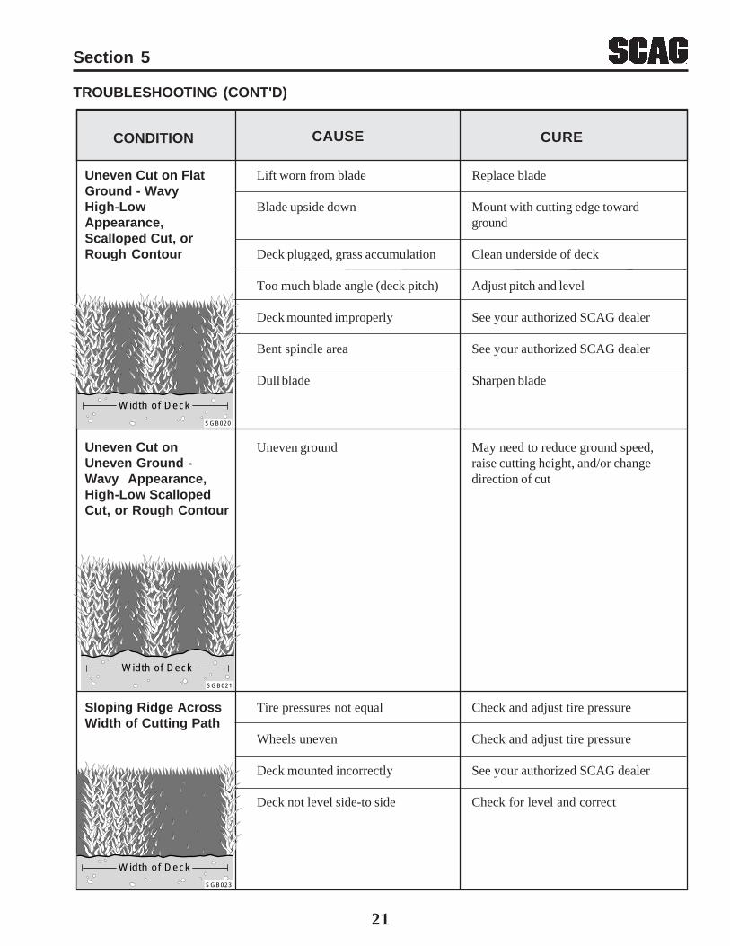
2. Push the cutting height adjustment foot pedal all theway forward using your right foot until it locks inplace. (Figure 4-5, page 19)
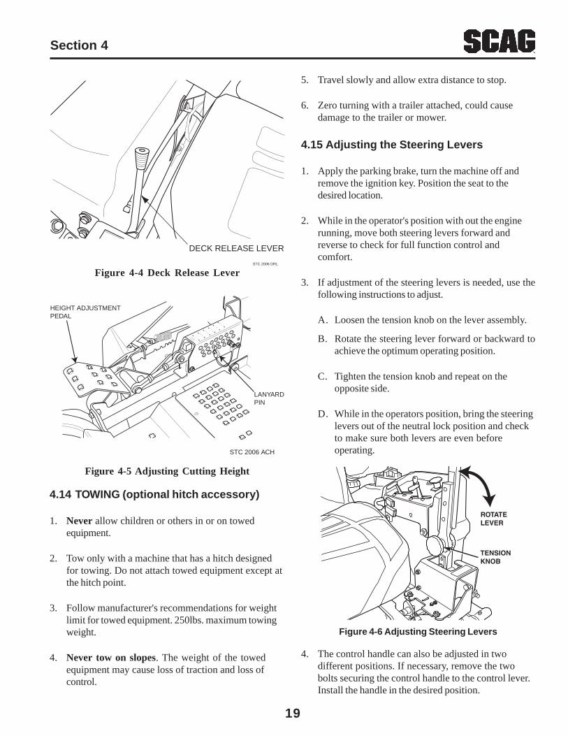
3. Insert the lanyard pin into the cutting height index atthe desired cutting height. Push forward on the decklift foot lever, hold in place and pull back on the deckrelease lever, (Figure 4-4). Slowly release the footpedal. A deck height decal is located on the cuttingheight index as an aid in adjusting the deck to thedesired height. (Figure 4-5)
WARNING:
4. Keep mower and discharge chute clean.
5. When mowing wet or tall grass, mow the grasstwice. Raise the mower to the highest setting for thefirst pass and then make a second pass to the desiredheight.
6. Use a slow travel speed for trimming purposes.
19
Section 4
Figure 4-5 Adjusting Cutting Height
Figure 4-4 Deck Release Lever
4.14 TOWING (optional hitch accessory)
1. Never allow children or others in or on towedequipment.
2. Tow only with a machine that has a hitch designedfor towing. Do not attach towed equipment except atthe hitch point.
3. Follow manufacturer's recommendations for weightlimit for towed equipment. 250lbs. maximum towingweight.
4. Never tow on slopes. The weight of the towedequipment may cause loss of traction and loss ofcontrol.
HEIGHT ADJUSTMENTPEDAL
LANYARDPIN
STC 2006 ACH
CUT TI
NGHEIGHT 5
4 1/4 3
1/2 2
1/2
X
1 1/4
STC 2006 DRL
DECK RELEASE LEVER
5. Travel slowly and allow extra distance to stop.
6. Zero turning with a trailer attached, could causedamage to the trailer or mower.
4.15 Adjusting the Steering Levers
1. Apply the parking brake, turn the machine off andremove the ignition key. Position the seat to thedesired location.
2. While in the operator's position with out the enginerunning, move both steering levers forward andreverse to check for full function control andcomfort.
3. If adjustment of the steering levers is needed, use thefollowing instructions to adjust.
A. Loosen the tension knob on the lever assembly.
B. Rotate the steering lever forward or backward toachieve the optimum operating position.
C. Tighten the tension knob and repeat on theopposite side.
D. While in the operators position, bring the steeringlevers out of the neutral lock position and checkto make sure both levers are even beforeoperating.
4. The control handle can also be adjusted in twodifferent positions. If necessary, remove the twobolts securing the control handle to the control lever.Install the handle in the desired position.
Figure 4-6 Adjusting Steering Levers
TENSIONKNOB
ROTATELEVER

Section 5
20
Stringers - Occasional Low engine RPM Run engine at full RPMBlades of UncutGrass Ground speed too fast Slow speed to adjust for conditions
Wet grass Cut grass after it has dried out
Dull blades, incorrect sharpening Sharpen blades
Deck plugged, grass accumulation Clean underside of deck
Belts slipping Adjust belt tension
Streaking - Strips of Dull, worn blades Sharpen bladesUncut Grass in CuttingPath Incorrect blade sharpening Sharpen blades
Low engine RPM Run engine at full RPM
Belt slipping Adjust belt tension
Deck plugged, grass accumulation Clean underside of deck
Ground speed too fast Slow speed to adjust for conditions
Wet grass Cut grass after it has dried out
Bent blades Replace bladesWidth of Deck
SGB018
CONDITION CAUSE CURE
Width of Deck
SGB020
Width of
Deck
Width of
DeckSGB019
Streaking - Strips of Not enough overlapping Increase the overlap of eachUncut Grass Between between rows passCutting Paths
TROUBLESHOOTING CUTTING CONDITIONS
Section 5
21
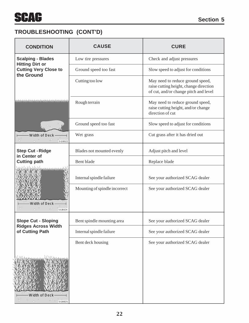
Uneven Cut on Flat Lift worn from blade Replace bladeGround - WavyHigh-Low Blade upside down Mount with cutting edge towardAppearance, groundScalloped Cut, orRough Contour Deck plugged, grass accumulation Clean underside of deck
Too much blade angle (deck pitch) Adjust pitch and level
Deck mounted improperly See your authorized SCAG dealer
Bent spindle area See your authorized SCAG dealer
Dull blade Sharpen blade
TROUBLESHOOTING (CONT'D)
Sloping Ridge Across Tire pressures not equal Check and adjust tire pressureWidth of Cutting Path
Wheels uneven Check and adjust tire pressure
Deck mounted incorrectly See your authorized SCAG dealer
Deck not level side-to side Check for level and correct
CONDITION CAUSE CURE
Uneven Cut on Uneven ground May need to reduce ground speed,Uneven Ground - raise cutting height, and/or changeWavy Appearance, direction of cutHigh-Low ScallopedCut, or Rough Contour
Width of Deck
SGB020
Width of Deck
SGB021
Width of Deck
SGB023
Section 5
22
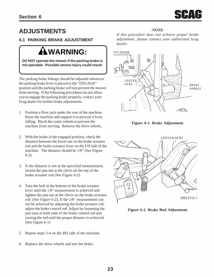
Scalping - Blades Low tire pressures Check and adjust pressuresHitting Dirt orCutting Very Close to Ground speed too fast Slow speed to adjust for conditionsthe Ground
Cutting too low May need to reduce ground speed,raise cutting height, change directionof cut, and/or change pitch and level
Rough terrain May need to reduce ground speed,raise cutting height, and/or changedirection of cut
Ground speed too fast Slow speed to adjust for conditions
Wet grass Cut grass after it has dried out
Step Cut - Ridge Blades not mounted evenly Adjust pitch and levelin Center ofCutting path Bent blade Replace blade
Internal spindle failure See your authorized SCAG dealer
Mounting of spindle incorrect See your authorized SCAG dealer
Slope Cut - Sloping Bent spindle mounting area See your authorized SCAG dealerRidges Across Widthof Cutting Path Internal spindle failure See your authorized SCAG dealer
Bent deck housing See your authorized SCAG dealer
CONDITION CAUSE CURE
Width of Deck
SGB024
Width of Deck
SGB025
Width of Deck
SGB022
TROUBLESHOOTING (CONT'D)
Section 6
23
ADJUSTMENTS6.1 PARKING BRAKE ADJUSTMENT
WARNING:DO NOT operate the mower if the parking brake isnot operable. Possible severe injury could result.
The parking brake linkage should be adjusted wheneverthe parking brake lever is placed in the “ENGAGE”position and the parking brake will not prevent the mowerfrom moving. If the following procedures do not allowyou to engage the parking brake properly, contact yourScag dealer for further brake adjustments.
1. Position a floor jack under the rear of the machine.Raise the machine and support it to prevent it fromfalling. Block the caster wheels to prevent themachine from moving. Remove the drive wheels.
2. With the brake in the engaged position, check thedistance between the lower nut on the brake actuatorrod and the brake actuator lever on the LH side of themachine. The distance should be 1/8" (See Figure6-2).
3. If the distance is not at the specified measurement,loosen the jam nut at the clevis on the top of thebrake actuator rod (See Figure 6-2).
4. Turn the bolt at the bottom of the brake actuatorlever until the 1/8" measurement is achieved andtighten the jam nut at the clevis on the brake actuatorrod. (See Figure 6-2). If the 1/8" measurement cannot be achieved by adjusting the brake actuator rod,adjust the brake control rod. Adjust by loosening thejam nuts at both ends of the brake control rod andturning the rod until the proper distance is achieved.(See Figure 6-1)
5. Repeat steps 2-4 on the RH side of the machine.
6. Replace the drive wheels and test the brake.
Figure 6-2. Brake Rod Adjustment
Figure 6-1. Brake Adjustment
LOOSEN HERE
1/8"
390S0153-1
-NOTE-If this procedure does not achieve proper brakeadjustment, please contact your authorized Scagdealer.
LOOSENHERE
STC2002BA
BRAKEHANDLE
Section 6
24
6.2 TRAVEL ADJUSTMENTS
Neutral or tracking adjustments will need to be made if:
A. The steering control levers are in the neutralposition and the machine creeps forward orbackward. (See Neutral Adjustment).
B. The steering control levers are in the full forwardposition and the mower pulls to one side or theother when traveling in a forward direction.(Tracking Adjustment, See Page 25).
Neutral Adjustment
1. Be sure the dump valve levers are in the run positionand the steering control levers are in the neutral lockposition.
2. With an operator in the seat, start the engine anddisengage the parking brake.
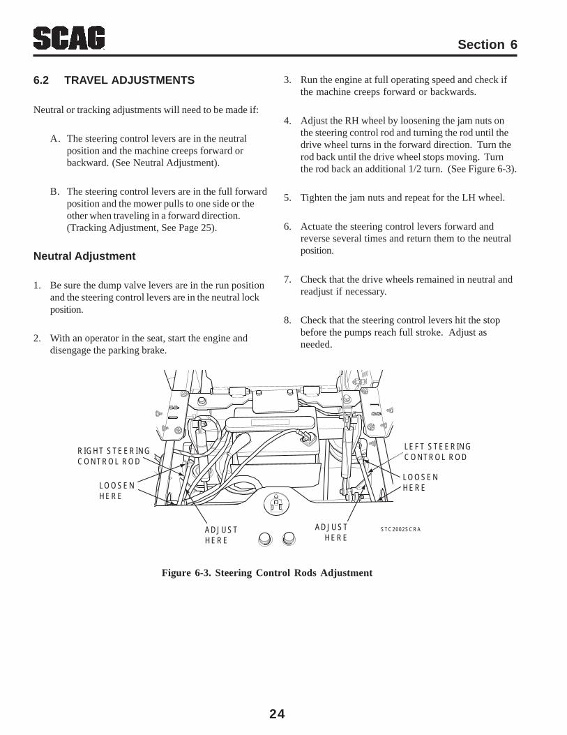
Figure 6-3. Steering Control Rods Adjustment
3. Run the engine at full operating speed and check ifthe machine creeps forward or backwards.
4. Adjust the RH wheel by loosening the jam nuts onthe steering control rod and turning the rod until thedrive wheel turns in the forward direction. Turn therod back until the drive wheel stops moving. Turnthe rod back an additional 1/2 turn. (See Figure 6-3).
5. Tighten the jam nuts and repeat for the LH wheel.
6. Actuate the steering control levers forward andreverse several times and return them to the neutralposition.
7. Check that the drive wheels remained in neutral andreadjust if necessary.
8. Check that the steering control levers hit the stopbefore the pumps reach full stroke. Adjust asneeded.
ADJUST HERE
ADJUSTHERE
LEFT STEERINGCONTROL ROD
RIGHT STEERINGCONTROL ROD
LOOSENHERELOOSEN
HERE
STC2002SCRA
Section 6
25
Tracking Adjustment
Stop the engine and remove the key from theignition before making any adjustments. Wait forall moving parts to come to a complete stopbefore beginning work.
The engine and drive unit can get hot duringoperation causing burn injuries. Allow engineand drive components to cool before making anyadjustments.
-NOTE-Before proceeding with this adjustment, be surethat the caster wheels turn freely and that the tirepressure in the drive wheels is correct. If the tirepressure is not correct, the machine will pull tothe side with the lower pressure.
1. If at full speed the mower pulls right, it is anindication that the left wheel is turning faster than theright wheel. To adjust this condition, proceed asfollows:
A. Stop the machine and place the steering controllevers in the neutral position. Loosen the locknuts securing the ball joints at each end of theLH steering control rod. Rotate the control rodto shorten the rod and tighten the lock nuts.This will cause the control rod to stroke the LHpump less, slowing down the LH wheel. (SeeFigure 6-3).
-NOTE-If after making the adjustment as outlined in step1A, the machine creeps forward or backward, theneutral adjustment must be made as described onpage 24.
2. If at full speed the mower pulls left, it is an indicationthat the right wheel is turning faster than the leftwheel. To adjust this condition, proceed as follows:
CAUTION:
CAUTION:
A. Stop the machine and place the steering controllevers in the neutral position. Loosen the locknuts securing the ball joints at each end of theRH steering control rod. Rotate the control rodto shorten the rod and tighten the lock nuts.This will cause the control rod to stroke the RHpump less, slowing down the RH wheel. (SeeFigure 6-3).
6.5 BELT ALIGNMENT
Belt alignment is important for proper performance ofyour Scag mower. If you experience frequent belt wearor breakage, see your authorized Scag service center forbelt adjustment.
All drive belts and cutter deck belts are spring loaded andself-tensioning. The belts should be checked periodicallyfor proper alignment and wear.
WARNING:Before removing any guards, shut theengine off and remove the ignition key.
6.4 BELT ADJUSTMENT
-NOTE-If after making the adjustment as outlined in step2A, the machine creeps forward or backward, theneutral adjustment must be made as described onpage 24.
6.3 THROTTLE CONTROL AND CHOKE ADJUSTMENTS
These adjustments must be performed by your Scagdealer to ensure proper and efficient running of theengine. Should either need adjustment, contact yourauthorized Scag service center.
Section 6
26
6.6 CUTTER DECK ADJUSTMENTS
Cutter deck level, pitch and height are set at the factory.However, if these adjustments should ever need to bemade, the following procedures will aid in obtaining theproper cutter deck adjustment.
-NOTE-Before proceeding with the cutter deckadjustments, be sure that all tires are properlyinflated.
Cutter Deck Level
The cutter deck should be level from side-to-side forproper cutting performance. To check for level, be surethat the mower is on a flat, level surface, the tires areproperly inflated and the cutter deck is set at the mostcommon cutting height that you will use. On the RH sideof the machine, check the distance from the top of thecutter deck to the floor. Next check the distance fromthe top of the cutter deck to the floor on the LH side ofthe machine. Both measurements should be the same.If the two measurements are different, the cutter decklevel must be adjusted as follows:
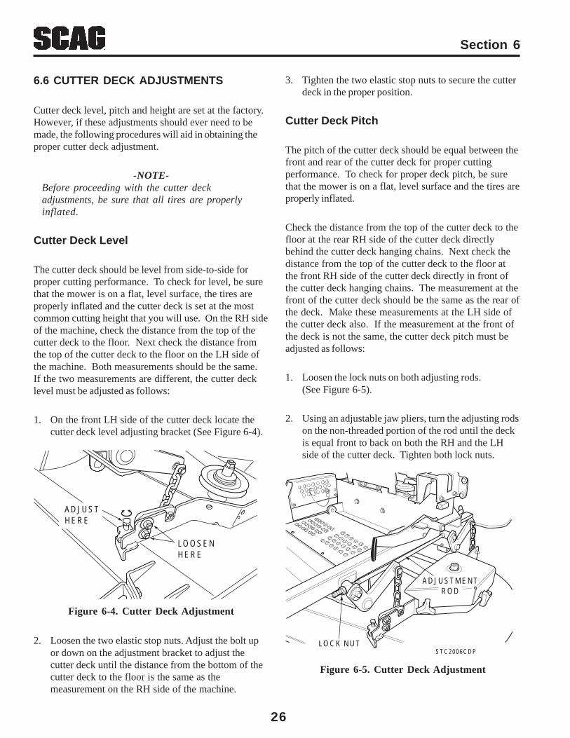
1. On the front LH side of the cutter deck locate thecutter deck level adjusting bracket (See Figure 6-4).
Figure 6-4. Cutter Deck Adjustment
2. Loosen the two elastic stop nuts. Adjust the bolt upor down on the adjustment bracket to adjust thecutter deck until the distance from the bottom of thecutter deck to the floor is the same as themeasurement on the RH side of the machine.
3. Tighten the two elastic stop nuts to secure the cutterdeck in the proper position.
Cutter Deck Pitch
The pitch of the cutter deck should be equal between thefront and rear of the cutter deck for proper cuttingperformance. To check for proper deck pitch, be surethat the mower is on a flat, level surface and the tires areproperly inflated.
Check the distance from the top of the cutter deck to thefloor at the rear RH side of the cutter deck directlybehind the cutter deck hanging chains. Next check thedistance from the top of the cutter deck to the floor atthe front RH side of the cutter deck directly in front ofthe cutter deck hanging chains. The measurement at thefront of the cutter deck should be the same as the rear ofthe deck. Make these measurements at the LH side ofthe cutter deck also. If the measurement at the front ofthe deck is not the same, the cutter deck pitch must beadjusted as follows:
1. Loosen the lock nuts on both adjusting rods.(See Figure 6-5).
2. Using an adjustable jaw pliers, turn the adjusting rodson the non-threaded portion of the rod until the deckis equal front to back on both the RH and the LHside of the cutter deck. Tighten both lock nuts.
LOOSEN HERE
ADJUST HERE
Figure 6-5. Cutter Deck Adjustment
LOCK NUT
ADJUSTMENTROD
STC2006CDP
Section 6
27
Cutter Deck Height
The cutter deck height adjustment is made to ensure thatthe cutter deck is cutting at the height indicated on thecutting height index gauge. To check for proper deckheight, be sure that the mower is on a flat, level surfaceand the tires are properly inflated.
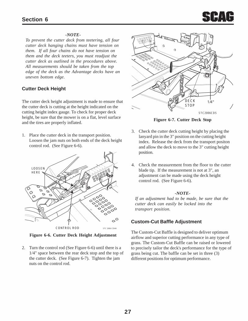
1. Place the cutter deck in the transport position.Loosen the jam nuts on both ends of the deck heightcontrol rod. (See Figure 6-6).
Figure 6-6. Cutter Deck Height Adjustment
2. Turn the control rod (See Figure 6-6) until there is a1/4" space between the rear deck stop and the top ofthe cutter deck. (See Figure 6-7). Tighten the jamnuts on the control rod.
3. Check the cutter deck cutting height by placing thelanyard pin in the 3" position on the cutting heightindex. Release the deck from the transport positonand allow the deck to move to the 3" cutting heightposition.
4. Check the measurement from the floor to the cutterblade tip. If the measurement is not at 3", anadjustment can be made using the deck heightcontrol rod. (See Figure 6-6).
-NOTE-If an adjustment had to be made, be sure that thecutter deck can easily be locked into thetransport position.
Custom-Cut Baffle Adjustment
The Custom-Cut Baffle is designed to deliver optimumairflow and superior cutting performance in any type ofgrass. The Custom-Cut Baffle can be raised or loweredto precisely tailor the deck's performance for the type ofgrass being cut. The baffle can be set in three (3)different positions for optimum performance.
Figure 6-7. Cutter Deck Stop
-NOTE-To prevent the cutter deck from teetering, all fourcutter deck hanging chains must have tension onthem. If all four chains do not have tension onthem and the deck teeters, you must readjust thecutter deck as outlined in the procedures above.All measurements should be taken from the topedge of the deck as the Advantage decks have anuneven bottom edge.
STC 2006 CDHACONTROL ROD
LOOSENHERE
CUT TI
NGHEIGHT 5
4 1/4 3
1/2 2
1/2
X
1 1/4
STC2006CDS
DECK STOP
1/4"
Section 6
28
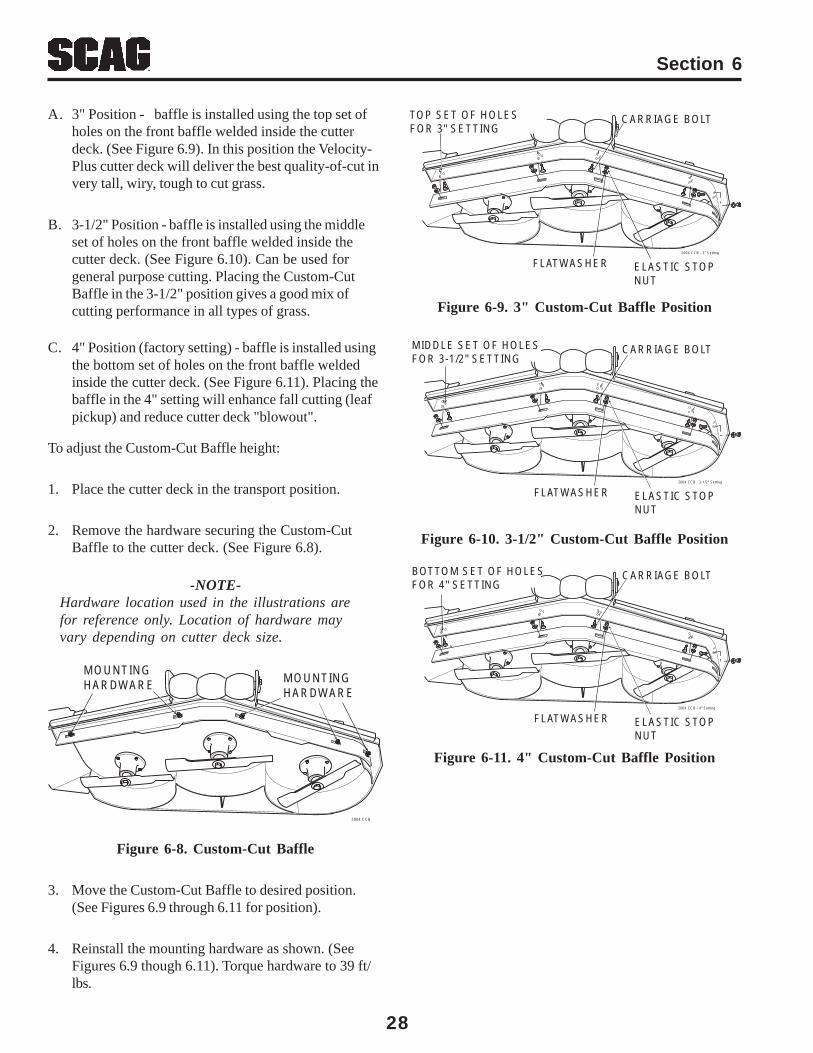
To adjust the Custom-Cut Baffle height:
1. Place the cutter deck in the transport position.
2. Remove the hardware securing the Custom-CutBaffle to the cutter deck. (See Figure 6.8).
-NOTE-Hardware location used in the illustrations arefor reference only. Location of hardware mayvary depending on cutter deck size.
Figure 6-8. Custom-Cut Baffle
3. Move the Custom-Cut Baffle to desired position.(See Figures 6.9 through 6.11 for position).
4. Reinstall the mounting hardware as shown. (SeeFigures 6.9 though 6.11). Torque hardware to 39 ft/lbs.
Figure 6-11. 4" Custom-Cut Baffle Position
Figure 6-10. 3-1/2" Custom-Cut Baffle Position
2004 CCB
MOUNTINGHARDWARE MOUNTING
HARDWARE
2004 CCB - 3" Setting
CARRIAGE BOLTTOP SET OF HOLESFOR 3" SETTING
FLATWASHER ELASTIC STOPNUT
2004 CCB - 3-1/2" Setting
CARRIAGE BOLTMIDDLE SET OF HOLESFOR 3-1/2" SETTING
FLATWASHER ELASTIC STOPNUT
2004 CCB - 4" Setting
CARRIAGE BOLTBOTTOM SET OF HOLESFOR 4" SETTING
FLATWASHER ELASTIC STOPNUT
C. 4" Position (factory setting) - baffle is installed usingthe bottom set of holes on the front baffle weldedinside the cutter deck. (See Figure 6.11). Placing thebaffle in the 4" setting will enhance fall cutting (leafpickup) and reduce cutter deck "blowout".
Figure 6-9. 3" Custom-Cut Baffle Position
A. 3" Position - baffle is installed using the top set ofholes on the front baffle welded inside the cutterdeck. (See Figure 6.9). In this position the Velocity-Plus cutter deck will deliver the best quality-of-cut invery tall, wiry, tough to cut grass.
B. 3-1/2" Position - baffle is installed using the middleset of holes on the front baffle welded inside thecutter deck. (See Figure 6.10). Can be used forgeneral purpose cutting. Placing the Custom-CutBaffle in the 3-1/2" position gives a good mix ofcutting performance in all types of grass.

Section 7
29
7.1 MAINTENANCE CHART - RECOMMENDED SERVICE INTERVALS
* Perform these maintenance procedures more frequently under extreme dusty or dirty conditions.
MAINTENANCE
HOURSBreak-In 8 20 40 100 200 500 Procedure Comments(First 10)
X Check all hardware for tightness
X Check hydraulic oil level See paragraph 7.3
X Check all belts for proper alignment See paragraph 7.8
X Check hydraulic hoses for leaks Use extreme caution whenchecking the hydraulic hosesSee paragraph 26
X Check seat belts for damage See paragraph 2.5
X Check engine oil level See paragraph 7.4
X *Clean mower See paragraph 7.11
X Check condition of blades See paragraph 7.9
X Apply grease to fittings See paragraph 7.2
X Check tire pressure See paragraph 7.10
X Change engine oil and filter See paragraph 7.4
X Check battery electrolyte level, See paragraph 7.7clean battery posts and cables
X Check belts for proper alignment See paragraph 7.8
X Apply grease to fittings See paragraph 7.2
X Change engine oil See paragraph 7.4
X *Clean air cleaner element See paragraph 7.6
30
Section 7
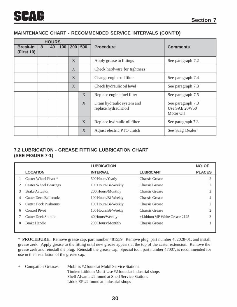
7.2 LUBRICATION - GREASE FITTING LUBRICATION CHART(SEE FIGURE 7-1)
LUBRICATION NO. OF
LOCATION INTERVAL LUBRICANT PLACES
1 Caster Wheel Pivot * 500 Hours/Yearly Chassis Grease 2
2 Caster Wheel Bearings 100 Hours/Bi-Weekly Chassis Grease 2
3 Brake Actuator 200 Hours/Monthly Chassis Grease 2
4 Cutter Deck Bellcranks 100 Hours/Bi-Weekly Chassis Grease 4
5 Cutter Deck Pusharms 100 Hours/Bi-Weekly Chassis Grease 2
6 Control Pivot 100 Hours/Bi-Weekly Chassis Grease 2
7 Cutter Deck Spindle 40 Hours/Weekly +Lithium MP White Grease 2125 3
8 Brake Handle 200 Hours/Monthly Chassis Grease 1
* PROCEDURE: Remove grease cap, part number 481559. Remove plug, part number 482028-01, and installgrease zerk. Apply grease to the fitting until new grease appears at the top of the caster extension. Remove thegrease zerk and reinstall the plug. Reinstall the grease cap. Special tool, part number 47007, is recommended foruse in the installation of the grease cap.
+ Compatible Greases: Mobilix #2 found at Mobil Service StationsTimken Lithium Multi-Use #2 found at industrial shopsShell Alvania #2 found at Shell Service StationsLidok EP #2 found at industrial shops
MAINTENANCE CHART - RECOMMENDED SERVICE INTERVALS (CONT'D)
HOURSBreak-In 8 40 100 200 500 Procedure Comments(First 10)
X Apply grease to fittings See paragraph 7.2
X Check hardware for tightness
X Change engine oil filter See paragraph 7.4
X Check hydraulic oil level See paragraph 7.3
X Replace engine fuel filter See paragraph 7.5
X Drain hydraulic system and See paragraph 7.3replace hydraulic oil Use SAE 20W50
Motor Oil
X Replace hydraulic oil filter See paragraph 7.3
X Adjust electric PTO clutch See Scag Dealer
Section 7
31
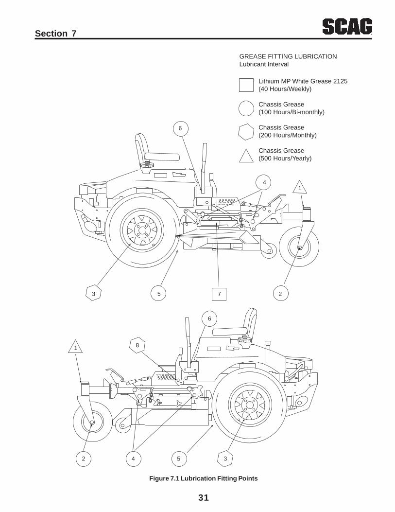
Figure 7.1 Lubrication Fitting Points
GREASE FITTING LUBRICATIONLubricant Interval
Lithium MP White Grease 2125(40 Hours/Weekly)
Chassis Grease(100 Hours/Bi-monthly)
Chassis Grease(200 Hours/Monthly)
Chassis Grease(500 Hours/Yearly)
3542
1 8
6
3 5 7 2
4
6
1
32
Section 7
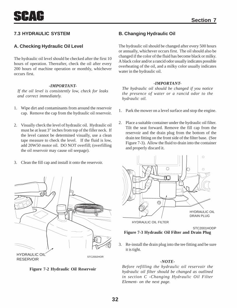
Figure 7-2 Hydraulic Oil Reservoir
7.3 HYDRAULIC SYSTEM
A. Checking Hydraulic Oil Level
The hydraulic oil level should be checked after the first 10hours of operation. Thereafter, check the oil after every200 hours of machine operation or monthly, whicheveroccurs first.
-IMPORTANT-If the oil level is consistently low, check for leaksand correct immediately.
1. Wipe dirt and contaminants from around the reservoircap. Remove the cap from the hydraulic oil reservoir.
2. Visually check the level of hydraulic oil. Hydraulic oilmust be at least 3" inches from top of the filler neck. Ifthe level cannot be determined visually, use a cleantape measure to check the level. If the fluid is low,add 20W50 motor oil. DO NOT overfill; (overfillingthe oil reservoir may cause oil seepage).
3. Clean the fill cap and install it onto the reservoir.
B. Changing Hydraulic Oil
The hydraulic oil should be changed after every 500 hoursor annually, whichever occurs first. The oil should also bechanged if the color of the fluid has become black or milky.A black color and/or a rancid odor usually indicates possibleoverheating of the oil, and a milky color usually indicateswater in the hydraulic oil.
-IMPORTANT-The hydraulic oil should be changed if you noticethe presence of water or a rancid odor to thehydraulic oil.
1. Park the mower on a level surface and stop the engine.
2. Place a suitable container under the hydraulic oil filter.Tilt the seat forward. Remove the fill cap from thereservoir and the drain plug from the bottom of thedrain tee fitting on the front side of the filter base. (SeeFigure 7-3). Allow the fluid to drain into the containerand properly discard it.
Figure 7-3 Hydraulic Oil Filter and Drain Plug
3. Re-install the drain plug into the tee fitting and be sureit is tight.
-NOTE-Before refilling the hydraulic oil reservoir thehydraulic oil filter should be changed as outlinedin section C -Changing Hydraulic Oil FilterElement- on the next page.
HYDRAULIC OIL FILTER
HYDRAULIC OIL DRAIN PLUG
STC2001HODP
HYDRAULIC OILRESERVOIR
STC2002HOR
Section 7
33
C. Changing Engine Oil Filter
After the first 20 hours of operation, replace the engine oilfilter. Thereafter, replace the oil filter after every 200 hoursof operation or every month, whichever occurs first. Referto Engine Operator’s Manual for instructions.
-NOTE-The engine oil filter for the Honda engine issupplied by Scag Power Equipment. Use only thepart number listed in the illustrated parts list ofthis manual when replacing.
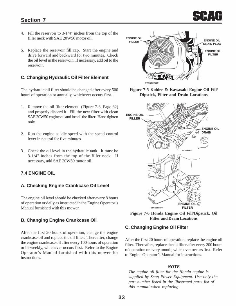
Figure 7-5 Kohler & Kawasaki Engine Oil Fill/Dipstick, Filter and Drain Locations
4. Fill the reservoir to 3-1/4" inches from the top of thefiller neck with SAE 20W50 motor oil.
5. Replace the reservoir fill cap. Start the engine anddrive forward and backward for two minutes. Checkthe oil level in the reservoir. If necessary, add oil to thereservoir.
C. Changing Hydraulic Oil Filter Element
The hydraulic oil filter should be changed after every 500hours of operation or annually, whichever occurs first.
1. Remove the oil filter element (Figure 7-3, Page 32)and properly discard it. Fill the new filter with cleanSAE 20W50 engine oil and install the filter. Hand tightenonly.
2. Run the engine at idle speed with the speed controllever in neutral for five minutes.
3. Check the oil level in the hydraulic tank. It must be3-1/4" inches from the top of the filler neck. Ifnecessary, add SAE 20W50 motor oil.
7.4 ENGINE OIL
A. Checking Engine Crankcase Oil Level
The engine oil level should be checked after every 8 hoursof operation or daily as instructed in the Engine Operator’sManual furnished with this mower.
B. Changing Engine Crankcase Oil
After the first 20 hours of operation, change the enginecrankcase oil and replace the oil filter. Thereafter, changethe engine crankcase oil after every 100 hours of operationor bi-weekly, whichever occurs first. Refer to the EngineOperator’s Manual furnished with this mower forinstructions.
ENGINE OILFILLER
ENGINE OILFILTER
ENGINE OILDRAIN PLUG
STC99KEOP
ENGINE OILFILLER
ENGINE OILDRAIN
STC05HNOD
Figure 7-6 Honda Engine Oil Fill/Dipstick, OilFilter and Drain Locations
ENGINE OILFILTERSTC05HNOF
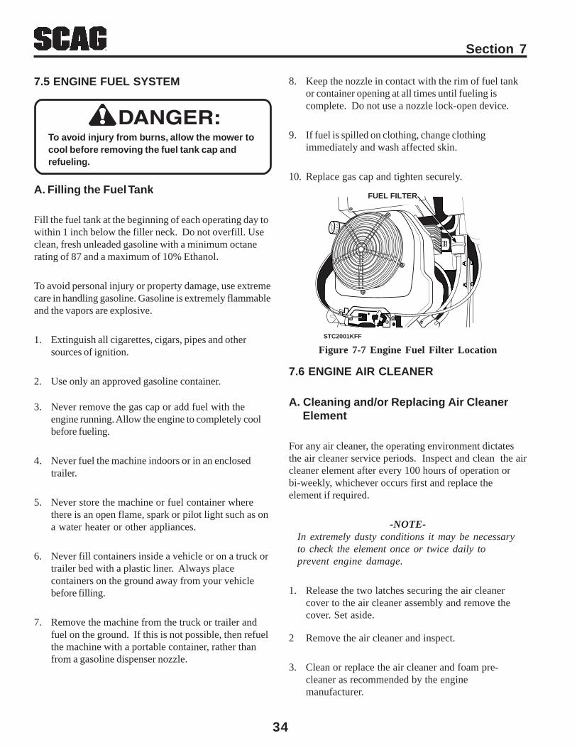
34
Section 7
Figure 7-7 Engine Fuel Filter Location
7.6 ENGINE AIR CLEANER
A. Cleaning and/or Replacing Air Cleaner Element
For any air cleaner, the operating environment dictatesthe air cleaner service periods. Inspect and clean the aircleaner element after every 100 hours of operation orbi-weekly, whichever occurs first and replace theelement if required.
-NOTE-In extremely dusty conditions it may be necessaryto check the element once or twice daily toprevent engine damage.
1. Release the two latches securing the air cleanercover to the air cleaner assembly and remove thecover. Set aside.
FUEL FILTER
STC2001KFF
3. Never remove the gas cap or add fuel with theengine running. Allow the engine to completely coolbefore fueling.
4. Never fuel the machine indoors or in an enclosedtrailer.
5. Never store the machine or fuel container wherethere is an open flame, spark or pilot light such as ona water heater or other appliances.
6. Never fill containers inside a vehicle or on a truck ortrailer bed with a plastic liner. Always placecontainers on the ground away from your vehiclebefore filling.
7. Remove the machine from the truck or trailer andfuel on the ground. If this is not possible, then refuelthe machine with a portable container, rather thanfrom a gasoline dispenser nozzle.
7.5 ENGINE FUEL SYSTEM
To avoid injury from burns, allow the mower tocool before removing the fuel tank cap andrefueling.
A. Filling the Fuel Tank
Fill the fuel tank at the beginning of each operating day towithin 1 inch below the filler neck. Do not overfill. Useclean, fresh unleaded gasoline with a minimum octanerating of 87 and a maximum of 10% Ethanol.
To avoid personal injury or property damage, use extremecare in handling gasoline. Gasoline is extremely flammableand the vapors are explosive.
1. Extinguish all cigarettes, cigars, pipes and othersources of ignition.
2. Use only an approved gasoline container.
8. Keep the nozzle in contact with the rim of fuel tankor container opening at all times until fueling iscomplete. Do not use a nozzle lock-open device.
9. If fuel is spilled on clothing, change clothingimmediately and wash affected skin.
10. Replace gas cap and tighten securely.
2 Remove the air cleaner and inspect.
3. Clean or replace the air cleaner and foam pre-cleaner as recommended by the enginemanufacturer.

Section 7
35
Lead-acid batteries produce flammable andexplosive gases. To avoid personal injurywhen checking, testing or chargingbatteries, DO NOT use smoking materialsnear batteries. Keep arcs, sparks and flamesaway from batteries. Provide properventilation and wear safety glasses.
WARNING:
WARNING:Battery posts, terminals, and related acces-sories contain lead and lead compounds,chemicals known to the State of Californiato cause cancer and reproductive harm.Wash hands after handling.
7.7 BATTERY
Electric storage battery fluid contains sulfuricacid which is POISON and can cause SEVERECHEMICAL BURNS. Avoid contact of fluidwith eyes, skin, or clothing. Use properprotective gear when handling batteries. DONOT tip any battery beyond 45° angle in anydirection. If fluid contact does occur, followfirst aid suggestions below.
BATTERY ELECTROLYTE FIRST AID
EXTERNAL CONTACT — Flush with water.
EYES — Flush with water for at least 15minutes and get medical attentionimmediately.
INTERNAL — Drink large quantities of water.Follow with Milk Of Magnesia, beaten egg,or vegetable oil. Get medical attentionimmediately. In case of internal contact, DONOT give fluids that would induce vomiting.
WARNING:
A. Charging the Battery
Refer to the battery charger’s manual for specificinstructions.
Under normal conditions the engine’s alternator will haveno problem keeping a charge on the battery. If thebattery has been completely discharged for a long periodof time, the alternator may not be able to recharge thebattery, and a battery charger will be required.
DO NOT charge a frozen battery. It may explode andcause injury. Let the battery warm before attaching acharger.
Whenever possible, remove the battery from the mowerbefore charging and make sure the electrolyte covers theplates in all cells.
BATTERIES PRODUCE EXPLOSIVE GASES.Charge the battery in a well ventilated spaceso gases produced while charging candissipate.
WARNING:
Charging rates between 3 and 50 amperes are satisfactoryif excessive gassing or spewing of electrolyte does not occuror the battery does not feel excessively hot (over 125°F).If spewing or gassing occurs or the temperature exceeds125°F, the charging rate must be reduced or temporarilystopped to permit cooling.
B. Jump Starting
1. The booster battery must be a 12 volt type. If a vehicleis used for jump starting, it must have a negative groundsystem.
2. When connecting the jumper cables, connect thepositive cable to the positive battery post, then connectthe negative cable to the negative battery post.
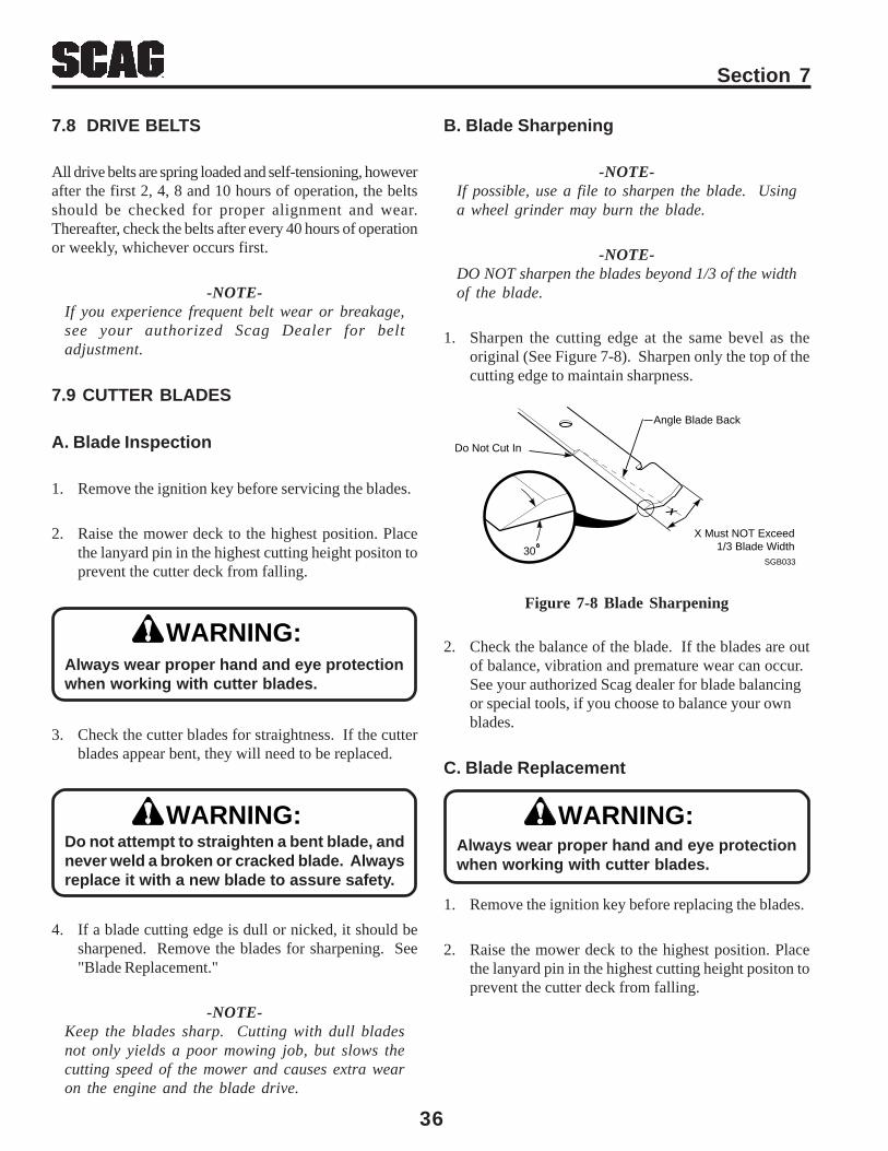
36
Section 7
2. Check the balance of the blade. If the blades are outof balance, vibration and premature wear can occur.See your authorized Scag dealer for blade balancingor special tools, if you choose to balance your ownblades.
C. Blade Replacement
1. Remove the ignition key before replacing the blades.
2. Raise the mower deck to the highest position. Placethe lanyard pin in the highest cutting height positon toprevent the cutter deck from falling.
Figure 7-8 Blade Sharpening
7.8 DRIVE BELTS
All drive belts are spring loaded and self-tensioning, howeverafter the first 2, 4, 8 and 10 hours of operation, the beltsshould be checked for proper alignment and wear.Thereafter, check the belts after every 40 hours of operationor weekly, whichever occurs first.
-NOTE-If you experience frequent belt wear or breakage,see your authorized Scag Dealer for beltadjustment.
7.9 CUTTER BLADES
A. Blade Inspection
1. Remove the ignition key before servicing the blades.
2. Raise the mower deck to the highest position. Placethe lanyard pin in the highest cutting height positon toprevent the cutter deck from falling.
WARNING:Always wear proper hand and eye protectionwhen working with cutter blades.
WARNING:
4. If a blade cutting edge is dull or nicked, it should besharpened. Remove the blades for sharpening. See"Blade Replacement."
-NOTE-Keep the blades sharp. Cutting with dull bladesnot only yields a poor mowing job, but slows thecutting speed of the mower and causes extra wearon the engine and the blade drive.
Do not attempt to straighten a bent blade, andnever weld a broken or cracked blade. Alwaysreplace it with a new blade to assure safety.
B. Blade Sharpening
-NOTE-If possible, use a file to sharpen the blade. Usinga wheel grinder may burn the blade.
-NOTE-DO NOT sharpen the blades beyond 1/3 of the widthof the blade.
1. Sharpen the cutting edge at the same bevel as theoriginal (See Figure 7-8). Sharpen only the top of thecutting edge to maintain sharpness.
3. Check the cutter blades for straightness. If the cutterblades appear bent, they will need to be replaced.
Always wear proper hand and eye protectionwhen working with cutter blades.
WARNING:
SGB033
Angle Blade Back
Do Not Cut In
X Must NOT Exceed1/3 Blade Width
X
30
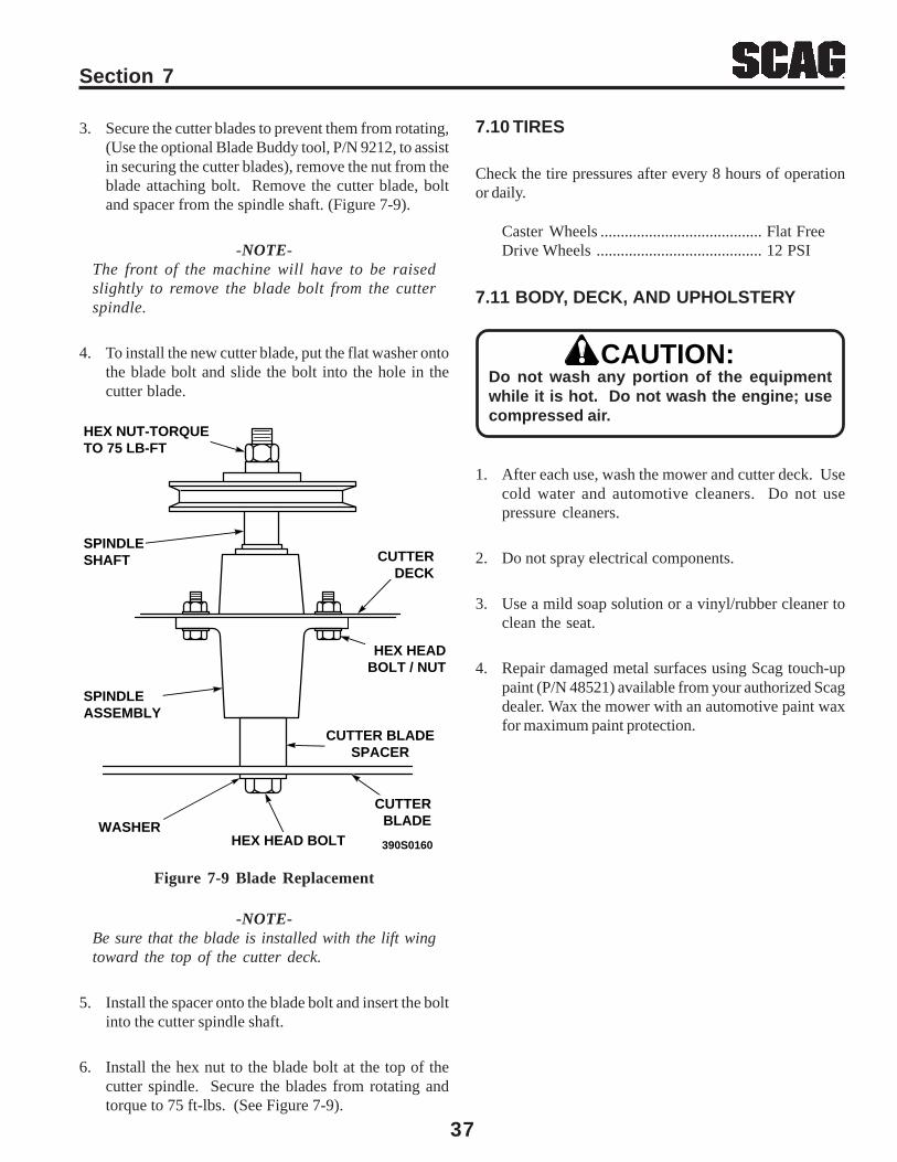
Section 7
37
Figure 7-9 Blade Replacement
7.10 TIRES
Check the tire pressures after every 8 hours of operationor daily.
Caster Wheels ........................................ Flat FreeDrive Wheels ......................................... 12 PSI
390S0160
WASHERHEX HEAD BOLT
CUTTERBLADE
SPINDLE ASSEMBLY
CUTTER BLADESPACER
HEX HEADBOLT / NUT
CUTTERDECK
SPINDLESHAFT
HEX NUT-TORQUETO 75 LB-FT
3. Secure the cutter blades to prevent them from rotating,(Use the optional Blade Buddy tool, P/N 9212, to assistin securing the cutter blades), remove the nut from theblade attaching bolt. Remove the cutter blade, boltand spacer from the spindle shaft. (Figure 7-9).
-NOTE-The front of the machine will have to be raisedslightly to remove the blade bolt from the cutterspindle.
4. To install the new cutter blade, put the flat washer ontothe blade bolt and slide the bolt into the hole in thecutter blade.
-NOTE-Be sure that the blade is installed with the lift wingtoward the top of the cutter deck.
5. Install the spacer onto the blade bolt and insert the boltinto the cutter spindle shaft.
6. Install the hex nut to the blade bolt at the top of thecutter spindle. Secure the blades from rotating andtorque to 75 ft-lbs. (See Figure 7-9).
CAUTION:
7.11 BODY, DECK, AND UPHOLSTERY
Do not wash any portion of the equipmentwhile it is hot. Do not wash the engine; usecompressed air.
1. After each use, wash the mower and cutter deck. Usecold water and automotive cleaners. Do not usepressure cleaners.
2. Do not spray electrical components.
3. Use a mild soap solution or a vinyl/rubber cleaner toclean the seat.
4. Repair damaged metal surfaces using Scag touch-uppaint (P/N 48521) available from your authorized Scagdealer. Wax the mower with an automotive paint waxfor maximum paint protection.
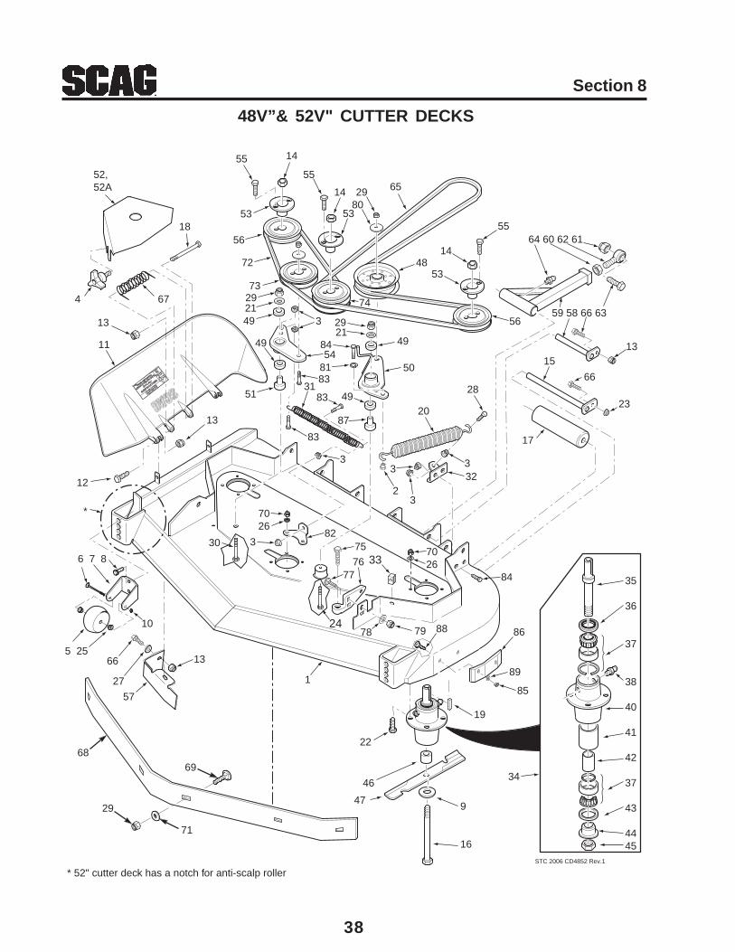
38
Section 8
48V”& 52V" CUTTER DECKS
STC 2006 CD4852 Rev.1
52,52A
4
18
67
13
12
13
11
6 7 8
5 25
10
57
9
16
47
35
36
37
38
40
41
42
37
43
4445
34
66
27
6869
29
64 60 62 61
59 58 66 63
23
15
17
13
66
71
*
* 52" cutter deck has a notch for anti-scalp roller
24
30
65
46
2921
7026
22
19
1
33
7026
55
55
55
14
14
14
53 53
53
56
56
72
73292149
49 49
49
3
3
3
3 3
2980
48
8454
8183
3183
83
51
87
50
20
28
322
382
75
7776
84
7978
13
74
88
89
85
86
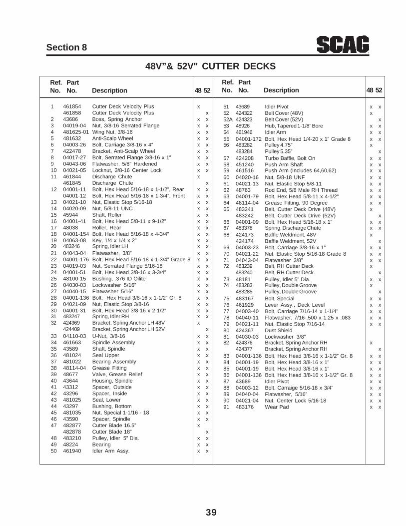
39
Section 8
1 461854 Cutter Deck Velocity Plus x461858 Cutter Deck Velocity Plus x
2 43686 Boss, Spring Anchor x x3 04019-04 Nut, 3/8-16 Serrated Flange x x4 481625-01 Wing Nut, 3/8-16 x x5 481632 Anti-Scalp Wheel x x6 04003-26 Bolt, Carriage 3/8-16 x 4” x x7 422478 Bracket, Anti-Scalp Wheel x x8 04017-27 Bolt, Serrated Flange 3/8-16 x 1” x x9 04043-06 Flatwasher, 5/8” Hardened x x10 04021-05 Locknut, 3/8-16 Center Lock x x11 461844 Discharge Chute x
461845 Discharge Chute x12 04001-11 Bolt, Hex Head 5/16-18 x 1-1/2”, Rear x x
04001-12 Bolt, Hex Head 5/16-18 x 1-3/4”, Front x x13 04021-10 Nut, Elastic Stop 5/16-18 x x14 04020-09 Nut, 5/8-11 UNC x x15 45944 Shaft, Roller x x16 04001-41 Bolt, Hex Head 5/8-11 x 9-1/2” x x17 48038 Roller, Rear x x18 04001-154 Bolt, Hex Head 5/16-18 x 4-3/4” x x19 04063-08 Key, 1/4 x 1/4 x 2” x x20 483246 Spring, Idler LH x x21 04043-04 Flatwasher, 3/8” x x22 04001-176 Bolt, Hex Head 5/16-18 x 1-3/4” Grade 8 x x23 04019-03 Nut, Serrated Flange 5/16-18 x x24 04001-51 Bolt, Hex Head 3/8-16 x 3-3/4” x x25 48100-15 Bushing, .376 ID Oilite x x26 04030-03 Lockwasher 5/16” x x27 04040-15 Flatwasher 5/16” x x28 04001-136 Bolt, Hex Head 3/8-16 x 1-1/2” Gr. 8 x x29 04021-09 Nut, Elastic Stop 3/8-16 x x30 04001-31 Bolt, Hex Head 3/8-16 x 2-1/2” x x31 483247 Spring, Idler RH x x32 424369 Bracket, Spring Anchor LH 48V x
424409 Bracket, Spring Anchor LH 52V x33 04110-03 U-Nut, 3/8-16 x x34 461663 Spindle Assembly x x35 43589 Shaft, Spindle x x36 481024 Seal Upper x x37 481022 Bearing Assembly x x38 48114-04 Grease Fitting x x39 48677 Valve, Grease Relief x x40 43644 Housing, Spindle x x41 43312 Spacer, Outside x x42 43296 Spacer, Inside x x43 481025 Seal, Lower x x44 43297 Bushing, Bottom x x45 481035 Nut, Special 1-1/16 - 18 x x46 43590 Spacer, Spindle x x47 482877 Cutter Blade 16.5” x
482878 Cutter Blade 18” x48 483210 Pulley, Idler 5” Dia. x x49 48224 Bearing x x50 461940 Idler Arm Assy. x x
48V”& 52V" CUTTER DECKS
Ref. PartNo. No. Description 48 52
Ref. PartNo. No. Description 48 52
51 43689 Idler Pivot x x52 424322 Belt Cover (48V) x52A 424323 Belt Cover (52V) x53 48926 Hub, Tapered 1-1/8” Bore x x54 461946 Idler Arm x x55 04001-172 Bolt, Hex Head 1/4-20 x 1” Grade 8 x x56 483282 Pulley 4.75” x
483284 Pulley 5.35” x57 424208 Turbo Baffle, Bolt On x x58 451240 Push Arm Shaft x x59 461516 Push Arm (Includes 64,60,62) x x60 04020-16 Nut, 5/8-18 UNF x x61 04021-13 Nut, Elastic Stop 5/8-11 x x62 48763 Rod End, 5/8 Male RH Thread x x63 04001-79 Bolt, Hex Head 5/8-11 x 4-1/2” x x64 48114-04 Grease Fitting, 90 Degree x x65 483241 Belt, Cutter Deck Drive (48V) x
483242 Belt, Cutter Deck Drive (52V) x66 04001-09 Bolt, Hex Head 5/16-18 x 1” x x67 483378 Spring, Discharge Chute x x68 424173 Baffle Weldment, 48V x
424174 Baffle Weldment, 52V x69 04003-23 Bolt, Carriage 3/8-16 x 1” x x70 04021-22 Nut, Elastic Stop 5/16-18 Grade 8 x x71 04043-04 Flatwasher 3/8” x x72 483239 Belt, RH Cutter Deck x
483240 Belt, RH Cutter Deck x73 48181 Pulley, Idler 5” Dia. x x74 483283 Pulley, Double Groove x
483285 Pulley, Double Groove x75 483167 Bolt, Special x x76 461929 Lever Assy., Deck Level x x77 04003-40 Bolt, Carriage 7/16-14 x 1-1/4" x x78 04040-11 Flatwasher, 7/16-.500 x 1.25 x .083 x x79 04021-11 Nut, Elastic Stop 7/16-14 x x80 424367 Dust Shield81 04030-03 Lockwasher 3/8”82 424376 Bracket, Spring Anchor RH x
424377 Bracket, Spring Anchor RH x83 04001-136 Bolt, Hex Head 3/8-16 x 1-1/2” Gr. 8 x x84 04001-19 Bolt, Hex Head 3/8-16 x 1” x x85 04001-19 Bolt, Hex Head 3/8-16 x 1” x x86 04001-136 Bolt, Hex Head 3/8-16 x 1-1/2” Gr. 8 x x87 43689 Idler Pivot x x88 04003-12 Bolt, Carraige 5/16-18 x 3/4” x x89 04040-04 Flatwasher, 5/16” x x90 04021-04 Nut, Center Lock 5/16-18 x x91 483176 Wear Pad x x
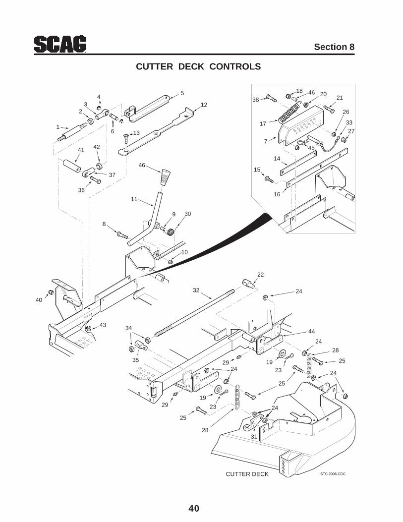
40
Section 8
CUTTER DECK CONTROLS
STC 2006 CDCCUTTER DECK
10
11
8
9
1
23
45
6
12
13
14
15
16
17
18
19
202138
26
27
33
19
23
2425
28
29
29
24
24
24
28
25
23
25
30
31
22
32 24
34
35
43
40
36
37
41 427
44
45
46
46

41
Section 8
Ref. PartNo. No. Description
1 482624 Rod, Deck Lift Linkage2 04020-28 Nut, Jam 1/2-20 LH Thread3 481766 Rod End, 1/2-20 Female Thread4 04050-10 Retaining Ring, 1/2” External “E”5 483062 Slide, Deck Height Adjust6 43487 Pin, Deck Lift7 423463 Bracket, Cutting Height Adjustment8 04001-22 Bolt, Hex Head 3/8-16 x 2-3/4”9 43668 Bushing .502 OD10 04021-09 Nut, Elastic Stop 3/8-1611 461874 Lever, Deck Latch12 422346 Slide, Cutting Height13 04014-03 Screw, Cap 5/16-18 x 3” FHHS14 422381 Guide, Short15 04003-04 Bolt, Carriage 5/16-18 x 1”16 422380 Guide, Long17 483177 Spring, Helper18 04021-05 Nut, 3/8-16 Center Lock19 04040-09 Flatwasher, 5/8-.656 x 1.312 x .09520 04019-04 Nut, 3/8-16 Serr. Flange21 04001-32 Bolt, Hex Head 3/8-16 x 1-1/4”22 43678 Swivel Joint LH23 04061-07 Cotter Pin, 3/16 x 1”24 04019-04 Nut, Serr. Flange 3/8-1625 04001-20 Bolt, Hex Head 3/8-16 x 1-1/2”26 04019-04 Nut, Serr. Flange 3/8-1627 04021-09 Nut, Elastic Stop 3/8-1628 48540 Chain29 48114-04 Grease Fitting, 1/4-28 Self Tap30 483181 Torsion Spring31 461929 Lever Assy., Deck Level32 04004-45 Stud, 1/2-13 x 20”33 04067-09 Pin
481547 Lanyard34 04020-09 Nut, 5/8-11 UNC35 43679 Swivel Joint RH36 04001-155 Bolt, Hex Head 1/2-13 x 5”37 481765 Rod End, 1/2-20 Female RH Thread38 04001-77 Bolt, Hex Head 3/8-16 x 3-1/2”39 43572 Spacer40 04021-02 Lock Nut, 1/4-2041 43630 Spacer42 04020-27 Nut, 1/2-20 UNF-2B43 04021-10 Nut, Elastic Stop 5/16-1844 45904 Lift Bellcrank Weldment, LH Rear
45905 Lift Bellcrank Weldment, RH Rear04041-14 Flatwasher, 1.0-1.062 x 1.5 x .04804050-08 Retaining Ring, 1” ext.
45 04062-04 Hair Pin Cotter, .177 x 3-1/4”46 481477 Grip, Deck Latch Lever
CUTTER DECK CONTROLS
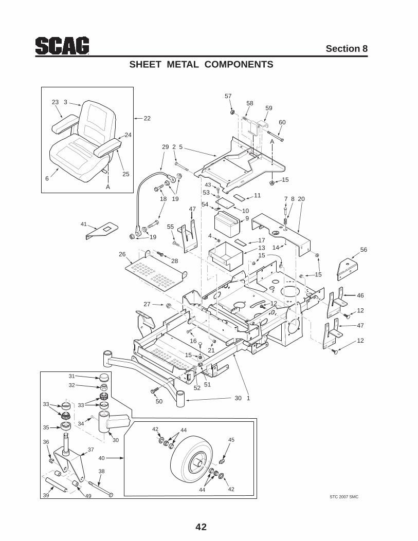
42
Section 8
SHEET METAL COMPONENTS
STC 2007 SMC
31
32
33
34
33
35
36
39
38
37
40
30
41
43
45
44
42
42
44
23 3
6
24
22
18 19
19
55
28
47
26
29 2 5
171315
4
117 8 20
109
15
46
12
47
12
30 1
16
21
27
25
14
A
A
15
12
51
50
52
15
49
53
54
56
5758
59
60

43
Section 8
Ref. PartNo. No. Description
SHEET METAL COMPONENTS
1 461918 Main Frame Assembly w/decals2 04001-73 Bolt, Hex Head 5/16-18 x 3-3/4”3 482632 Cushion, Back4 04019-04 Nut, Serr. Flange 3/8-165 461989 Plate, Seat Mounting w/decals6 482111 Cushion, Lower Seat7 43462 Pin Retainer, Spring8 481389 Spring9 ** Battery (not available through Scag)10 423571 Battery Cover11 482553 Battery Hold Down Pad12 04003-12 Bolt, Carr. 5/16-18 x 3/4”13 423556 Battery Box14 04060-01 Roll Pin, Spring 5/32 x 3/4”15 04019-03 Nut, Serr. Flange 5/16-1816 04001-19 Bolt, Hex Head 3/8-16 x 1”17 482552 Pad, Rubber18 04001-59 Bolt, Hex Head 1/4-20 x 1-1/4”19 04019-02 Nut, Serr. Flange 1/4-2020 451896 Seat Base Support21 04021-10 Nut, Elastic Stop 5/16-1822 483385 Seat Assembly w/ adj. rails23 482108 Arm Pad, RH
482110 Bracket, Armrest RH24 482107 Arm Pad, LH
482109 Bracket, Armrest LH25 482183 Channel, Armrest26 423557 Footplate27 04021-09 Nut, Elastic Stop 3/8-1628 04001-19 Bolt, Hex Head 3/8-16 x 1”29 48566 Cable, Seat Stop30 451826 Weldment, Caster Support
Ref. PartNo. No. Description
31 481559 Cap, Grease32 04021-20 Nut, Elastic Stop 1.0-1433 48668 Bearing Set34 482028-01 Plug, 1/4-2835 481025 Seal, 2.0” OD x 1.625” ID36 04021-07 Nut, Elastic Stop 1/2-1337 451471 Yoke, Front Caster Wheel38 04001-134 Bolt, Hex Head 1/2-13 x 7-1/2”39 43581 Sleeve40 9277 Caster Wheel Assembly (Incl. 42, 44, 45)41 424112 Bracket, Hour Meter42 482622 Seal43 04001-32 Bolt, Hex Head 3/8-16 x 1-1/4”44 482621 Roller Bearing45 48114-04 Fitting, Grease46 423575 Mounting Bracket, Oil Tank47 423764 Mounting Bracket, Fuel Tank48 482633 Seat Pan49 43584 Spacer, Caster Wheel50 04001-28 Bolt, Hex Head 7/16-14 x 1-1/4”51 04021-11 Nut, Elastic Stop 7/16-1452 04030-05 Lockwasher, 7/1653 04030-04 Lock Washer. 3/8 Spring54 04110-03 U-Nut, 3/8-1655 04003-04 Bolt, Carriage 5/16-18 x 1”56 423912 Bracket, Fuel Valve57 04021-05 Lock Nut, 3/8-16 Center Lock58 483371 Spring, Seat Latch59 451897 Seat Latch Weldment60 04001-100 Bolt, Hex Head 3/8-16 x 6”
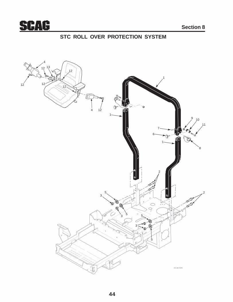
44
Section 8
STC ROLL OVER PROTECTION SYSTEM
1
23
4
2
5
4
3
3
55
5
STC 2007 ROPS
1
1
6
7
8
9 10
11
12
12
12
13
1212
12

45
Section 8
STC ROLL OVER PROTECTION SYSTEM
1 9512 STC Foldable ROPS Accessory (incl. all items listed)2 04001-145 Bolt, Hex Head 1/2-13 x 3-1/2”3 04021-19 Nut, Center Lock 1/2-134 483412 Retractable Seat Belt5 04040-13 Flatwasher, 1/2-.562 x 1.375 x .1096 481625-03 Thumb Screw, 5/16-18 NC x 3-4”7 04062-06 Hair Pin, Cotter8 483262 Pin9 04021-19 Nut, Center Lock 1/2-1310 424407 Bracket, Stop11 04001-145 Bolt, Hex Head 1/2-13 x 3-1/2”12 461990 Seat Hardware Kit, STC13 483451 Bracket
Ref. PartNo. No. Description
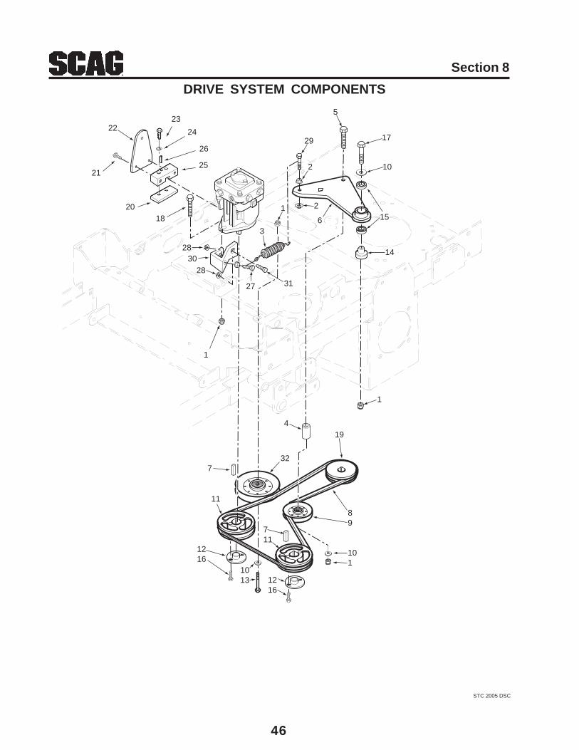
46
Section 8
DRIVE SYSTEM COMPONENTS
STC 2005 DSC
21
2223
24
25
20
1
27
28
3
1
1
26
19
89
101
11
711
7
1216
1013 12
16
18
32
4
6
5
14
10
17
2
2
29
15
2830
31

47
Section 8
1 04021-09 Nut, Elastic Stop 3/8-162 04019-04 Nut, Serrated Flange 3/8-163 483087 Spring, Pump Idler4 43286 Spacer5 04001-22 Bolt, Hex Head 3/8-16 x 2-3/4”6 461603 Idler Arm Assy., Pump Drive7 04063-14 Key, 5 x 5 x 25mm8 483172 Belt, Transmission9 483415 Pulley, 3-1/2” Dia. Idler10 04043-04 Flatwasher, 3/8-.391 x .938 x .10511 482744 Pulley, 5.75 OD Taper Bore12 482085 Hub, Tapered, 15mm Bore13 04001-45 Bolt, 3/8-16 x 2”14 43503 Pivot, Idler15 48224 Bearing16 04001-172 Bolt, Hex Head 1/4-20 x 1” Grade 817 04001-31 Bolt, Hex Head 3/8-16 x 2-1/2”18 04001-20 Bolt, Hex Head 3/8-16 x 1-1/2”19 483081 Pulley, 5.75 Dia. - 1.125” Bore20 421203 Clamp Plate21 04017-05 Hex Head Capscrew, 1/4-20 x 3/4”22 422969 Control Lever, Pump23 04017-05 Hex Head Capscrew, 1/4-20 x 3/4”24 04030-02 Lockwasher, 1/4”25 48829 Block, Pump Control26 04060-06 Roll Pin27 04001-136 Bolt, Hex Head 3/8-16 x 1-1/2” Grade 828 04019-04 Nut, Serr. Flange 3/8-1629 04001-136 Bolt, Hex Head 3/8-16 x 1-1/2” Grade 830 424137 Bracket31 04001-19 Bolt, Hex Head 3/8-16 x 1”32 483215 Pulley, 5” Dia. Idler
Ref. PartNo. No. Description
DRIVE SYSTEM COMPONENTS
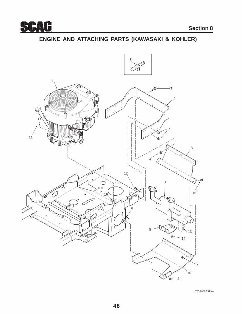
48
Section 8
ENGINE AND ATTACHING PARTS (KAWASAKI & KOHLER)
STC 2006 EAPKA
1
11
5
2
4
4
3
15
8
12
7
9
14
13
4
10
6
16
4

49
Section 8
ENGINE AND ATTACHING PARTS (KAWASAKI & KOHLER)
1 482932 Engine, Kawasaki (FH601V-AS29) x483281 Engine, Kohler (PS-75607) x482826 Engine, Kawasaki (FH680V-AS32) x
2 423770 Bumper, Rear x x x3 424107 Shield, Rear x x x4 04019-04 Nut, Serr. Flange 3/8-16 x x x5 482510 Extension, Oil Drain 2.3” x
482349 Extension, Oil Drain 4” x x6 04003-23 Bolt, Carr. 3/8-16 x 1” x x x7 04104-01 Bolt, 3/8-16 x 1” Torx x x
04001-32 Bolt, Hex Head 3/8-16 x 1-1/4” (61A) x8 483102 Muffler x
483268 Muffler x483266 Muffler x
9 424133 Bracket, Muffler x x x10 423555 Plate, Skid x x x11 04001-11 Bolt, Hex Head 5/16-18 x 1-1/2” x x x12 04001-19 Bolt, Hex Head 3/8-16 x 1” x x x13 04003-12 Bolt, Hex Head 5/16-18 x 3/4” x x x14 04019-03 Nut, Serr. Flange 5/16-18 x x x15 04003-31 Bolt, Carr. 3/8-16 x 3/4” x x x16 04019-03 Nut, Serr. Flange 5/16-18 x x x
Ref. PartNo. No. Description 19KAI 23CV 23KA
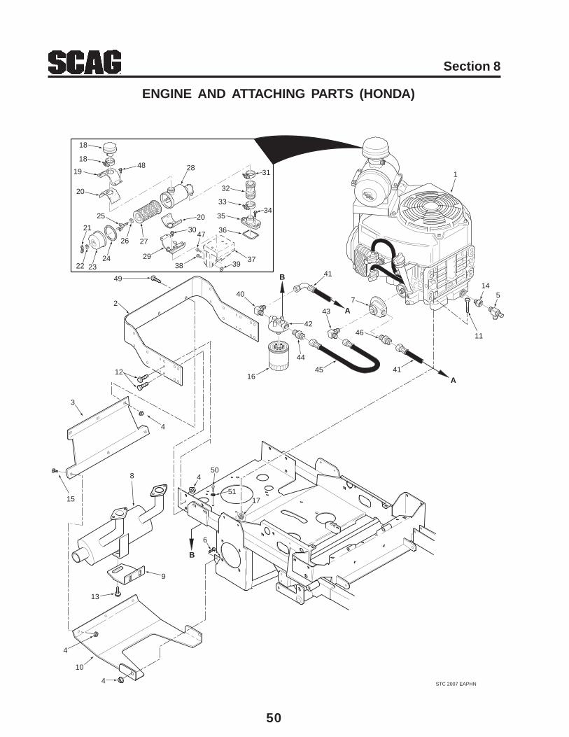
50
Section 8
ENGINE AND ATTACHING PARTS (HONDA)
STC 2007 EAPHN
1
11
5
49
2
4
4
3
15
8
12
9
14
13
4
10
6
17
A
4
A
18
19
20
21
22 2324
25
26 27
28
20
29
30
31
32
3334
35
36
3738 39
40
41
42
16
43
44
45
46
41
7
47
48
B
B
50
51
18
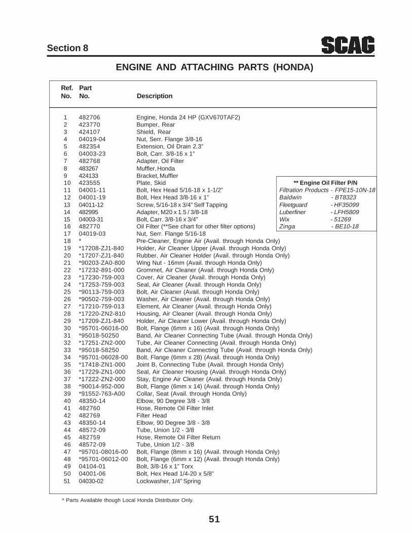
51
Section 8
1 482706 Engine, Honda 24 HP (GXV670TAF2)2 423770 Bumper, Rear3 424107 Shield, Rear4 04019-04 Nut, Serr. Flange 3/8-165 482354 Extension, Oil Drain 2.3”6 04003-23 Bolt, Carr. 3/8-16 x 1”7 482768 Adapter, Oil Filter8 483267 Muffler, Honda9 424133 Bracket, Muffler10 423555 Plate, Skid ** Engine Oil Filter P/N11 04001-11 Bolt, Hex Head 5/16-18 x 1-1/2” Filtration Products - FPE15-10N-1812 04001-19 Bolt, Hex Head 3/8-16 x 1” Baldwin - BT832313 04011-12 Screw, 5/16-18 x 3/4” Self Tapping Fleetguard - HF3509914 482995 Adapter, M20 x 1.5 / 3/8-18 Luberfiner - LFH580915 04003-31 Bolt, Carr. 3/8-16 x 3/4” Wix - 5126916 482770 Oil Filter (**See chart for other filter options) Zinga - BE10-1817 04019-03 Nut, Serr. Flange 5/16-1818 * Pre-Cleaner, Engine Air (Avail. through Honda Only)19 *17208-ZJ1-840 Holder, Air Cleaner Upper (Avail. through Honda Only)20 *17207-ZJ1-840 Rubber, Air Cleaner Holder (Avail. through Honda Only)21 *90203-ZA0-800 Wing Nut - 16mm (Avail. through Honda Only)22 *17232-891-000 Grommet, Air Cleaner (Avail. through Honda Only)23 *17230-759-003 Cover, Air Cleaner (Avail. through Honda Only)24 *17253-759-003 Seal, Air Cleaner (Avail. through Honda Only)25 *90113-759-003 Bolt, Air Cleaner (Avail. through Honda Only)26 *90502-759-003 Washer, Air Cleaner (Avail. through Honda Only)27 *17210-759-013 Element, Air Cleaner (Avail. through Honda Only)28 *17220-ZN2-810 Housing, Air Cleaner (Avail. through Honda Only)29 *17209-ZJ1-840 Holder, Air Cleaner Lower (Avail. through Honda Only)30 *95701-06016-00 Bolt, Flange (6mm x 16) (Avail. through Honda Only)31 *95018-50250 Band, Air Cleaner Connecting Tube (Avail. through Honda Only)32 *17251-ZN2-000 Tube, Air Cleaner Connecting (Avail. through Honda Only)33 *95018-58250 Band, Air Cleaner Connecting Tube (Avail. through Honda Only)34 *95701-06028-00 Bolt, Flange (6mm x 28) (Avail. through Honda Only)35 *17418-ZN1-000 Joint B, Connecting Tube (Avail. through Honda Only)36 *17229-ZN1-000 Seal, Air Cleaner Housing (Avail. through Honda Only)37 *17222-ZN2-000 Stay, Engine Air Cleaner (Avail. through Honda Only)38 *90014-952-000 Bolt, Flange (6mm x 14) (Avail. through Honda Only)39 *91552-763-A00 Collar, Seat (Avail. through Honda Only)40 48350-14 Elbow, 90 Degree 3/8 - 3/841 482760 Hose, Remote Oil Filter Inlet42 482769 Filter Head43 48350-14 Elbow, 90 Degree 3/8 - 3/844 48572-09 Tube, Union 1/2 - 3/845 482759 Hose, Remote Oil Filter Return46 48572-09 Tube, Union 1/2 - 3/847 *95701-08016-00 Bolt, Flange (8mm x 16) (Avail. through Honda Only)48 *95701-06012-00 Bolt, Flange (6mm x 12) (Avail. through Honda Only)49 04104-01 Bolt, 3/8-16 x 1” Torx50 04001-06 Bolt, Hex Head 1/4-20 x 5/8”51 04030-02 Lockwasher, 1/4” Spring
Ref. PartNo. No. Description
ENGINE AND ATTACHING PARTS (HONDA)
* Parts Available though Local Honda Distributor Only.
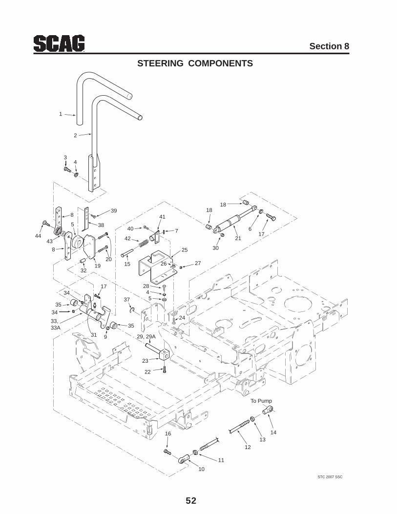
52
Section 8
STEERING COMPONENTS
STC 2007 SSC
1
2
34
7
8
38
39
1920
32
40
41
42
15
25
27
2845
35
35
34
9
34
29, 29A
22
37
16
10
11
1213
14
1818
30
21
617
31
17
33,33A
26
23
To Pump
24
8
4443
5
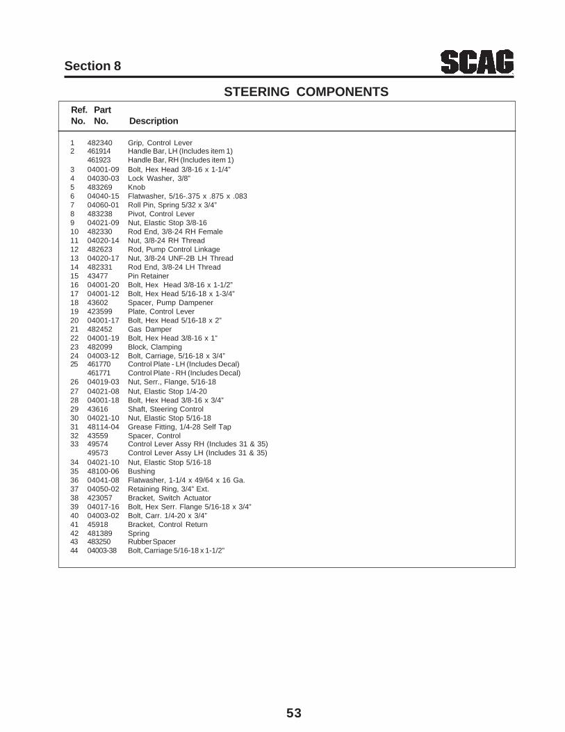
53
Section 8
1 482340 Grip, Control Lever2 461914 Handle Bar, LH (Includes item 1)
461923 Handle Bar, RH (Includes item 1)3 04001-09 Bolt, Hex Head 3/8-16 x 1-1/4”4 04030-03 Lock Washer, 3/8”5 483269 Knob6 04040-15 Flatwasher, 5/16-.375 x .875 x .0837 04060-01 Roll Pin, Spring 5/32 x 3/4”8 483238 Pivot, Control Lever9 04021-09 Nut, Elastic Stop 3/8-1610 482330 Rod End, 3/8-24 RH Female11 04020-14 Nut, 3/8-24 RH Thread12 482623 Rod, Pump Control Linkage13 04020-17 Nut, 3/8-24 UNF-2B LH Thread14 482331 Rod End, 3/8-24 LH Thread15 43477 Pin Retainer16 04001-20 Bolt, Hex Head 3/8-16 x 1-1/2”17 04001-12 Bolt, Hex Head 5/16-18 x 1-3/4”18 43602 Spacer, Pump Dampener19 423599 Plate, Control Lever20 04001-17 Bolt, Hex Head 5/16-18 x 2”21 482452 Gas Damper22 04001-19 Bolt, Hex Head 3/8-16 x 1”23 482099 Block, Clamping24 04003-12 Bolt, Carriage, 5/16-18 x 3/4”25 461770 Control Plate - LH (Includes Decal)
461771 Control Plate - RH (Includes Decal)26 04019-03 Nut, Serr., Flange, 5/16-1827 04021-08 Nut, Elastic Stop 1/4-2028 04001-18 Bolt, Hex Head 3/8-16 x 3/4”29 43616 Shaft, Steering Control30 04021-10 Nut, Elastic Stop 5/16-1831 48114-04 Grease Fitting, 1/4-28 Self Tap32 43559 Spacer, Control33 49574 Control Lever Assy RH (Includes 31 & 35)
49573 Control Lever Assy LH (Includes 31 & 35)34 04021-10 Nut, Elastic Stop 5/16-1835 48100-06 Bushing36 04041-08 Flatwasher, 1-1/4 x 49/64 x 16 Ga.37 04050-02 Retaining Ring, 3/4” Ext.38 423057 Bracket, Switch Actuator39 04017-16 Bolt, Hex Serr. Flange 5/16-18 x 3/4”40 04003-02 Bolt, Carr. 1/4-20 x 3/4”41 45918 Bracket, Control Return42 481389 Spring43 483250 Rubber Spacer44 04003-38 Bolt, Carriage 5/16-18 x 1-1/2”
Ref. PartNo. No. Description
STEERING COMPONENTS
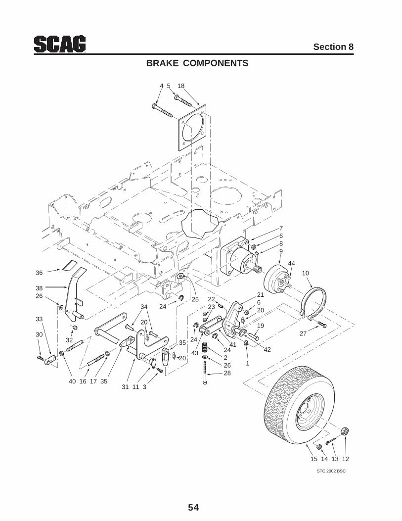
54
Section 8
BRAKE COMPONENTS
STC 2002 BSC
4 5 18
36
38 26
33
3032
40 16 17 35
34
20
31 11 3
2524
2223
2435
202422628
1
21620
1927
7689
15 14 13 12
10
44
4341
42
55
Section 8
1 04019-04 Nut, Serr. Flange 3/8-162 48807 Spring3 04001-08 Bolt, Hex Head 5/16-18 x 3/4”4 04001-163 Bolt, Hex Head 1/2-13 x 3-3/4”5 04001-52 Bolt, Hex Head 1/2-13 x 2-1/2”6 04021-19 Nut, 1/2-13 Center Lock7 483190 Wheel Motor, Hydro-Gear8 04063-25 Key, Woodruff 5/16 x 1”9 461438 Wheel Hub Assembly10 481601 Brake Band Assembly11 482061 Bushing, Self Align12 48680 Nut, Hex Castle 1.0-20 UNEF13 04061-06 Cotter Pin, 9/64 x 1-1/2”14 04028-02 Lug Nut, 1/2-2015 482044 (48”) Wheel Assembly 23 x 9.5 -12
481659 (48”) Rim482413 (52”) Wheel Assembly 23 x 9.5 -12482414 (52”) Rim482194 (48” & 52”) Tire 23 x 9.5 - 12
16 04004-46 Brake Rod Stud, 3/8-24 x 8.12517 04020-14 Nut, 3/8-24 UNF18 423279 Plate Weldment, Motor Backing19 04064-16 Clevis Pin, 3/8 x 1.93”20 04069-01 Pin, Rue Cotter 3/8 Dia.21 461471 Brake Linkage LH
461472 Brake Linkage RH22 48114-04 Grease Fitting, 1/4-2823 04020-25 Nut, 3/8-24 UNF24 04050-01 Retaining Ring, .625 Ext.25 04021-10 Nut, Elastic Stop 5/16-1826 04041-07 Flatwasher, 3/8-.391 x .938 x .10527 04001-31 Bolt, Hex Head 3/8-16 x 2-1/2”28 04001-166 Bolt, Hex Head 3/8-24 x 3-3/4”29 04061-02 Cotter Pin, 3/32 x 3/4”30 04001-20 Bolt, Hex Head 3/8-16 x 1-1/2”31 451463 Brake Shaft32 04021-09 Nut, Elastic Stop 3/8-1633 48544 Rod End, 3/8-24 LH Thread34 04064-02 Clevis Pin, 3/8 x 1.0635 48343-04 Clevis, 3/8-2436 482102 Grip, Brake Lever37 04019-04 Nut, Serr. Flange 3/8-1638 461509 Brake Lever (includes item 36)39 04001-22 Bolt, Hex Head 3/8-16 x 2-3/4”40 04020-17 Nut, 3/8-24 UNF-2B LH Thread41 422483 Lever, Brake42 45974 Shaft Weldment, Pivot43 43495 Pin, Pivot44 04008-01 Bolt, Serr. Flange 1/2-20 x 4.563”
Ref. PartNo. No. Description
BRAKE COMPONENTS
* Common hardware which should be purchased locally. All bolts Grade 5 plated, all other fasteners zinc plated.
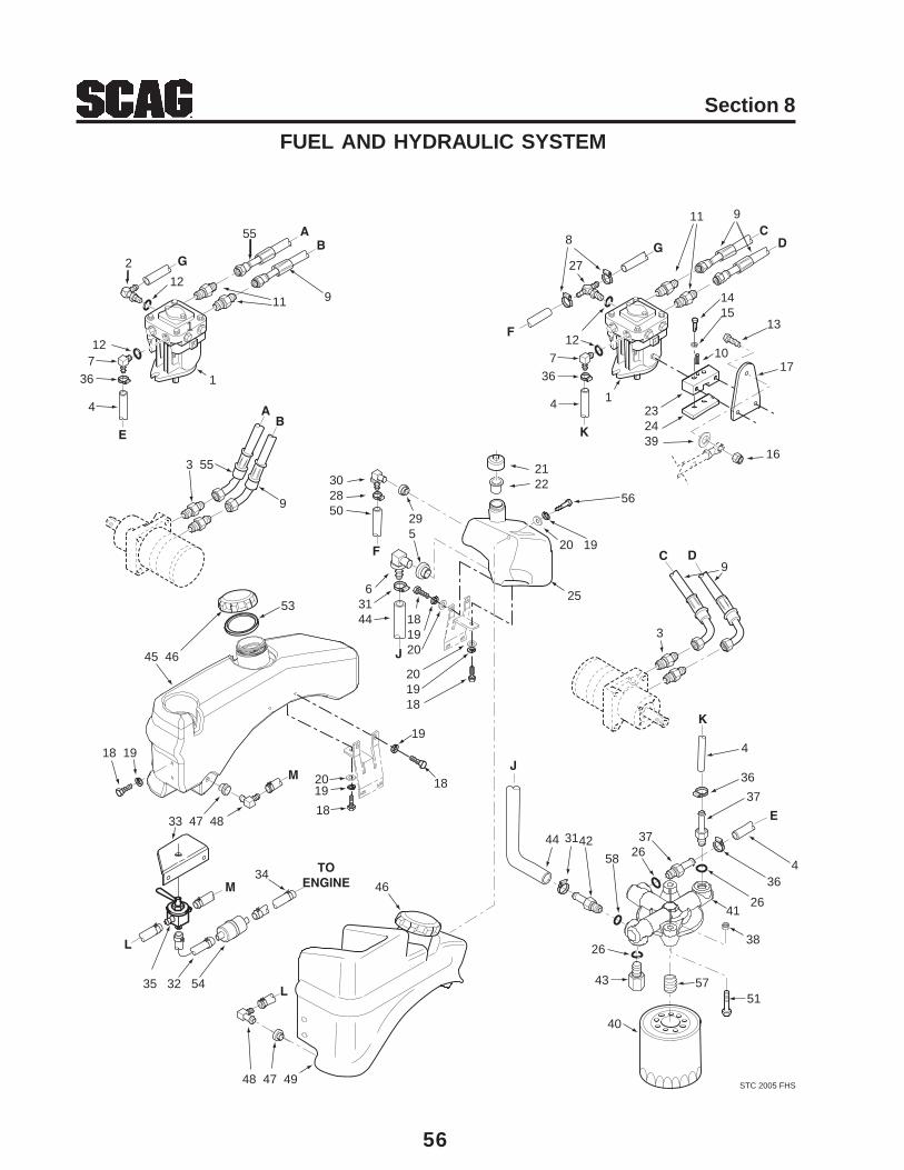
56
Section 8
FUEL AND HYDRAULIC SYSTEM
STC 2005 FHS
M
L
J
TOENGINEM
L
AB
DC
K
D
F
CB
E
A
GG
F
2
129
8
27
1
1
1
4
11
12 12
11
10
1415
9
13
17
232439
162122
20 19
9
3
302850
63144 18
1920
201918
25
3 55
45 46
18 19
33 47 48
35 32 54
34
48 47 49
46
295
18
18
19
1920
9
55
56
736
4
736
53
E
3826
5157
J
K
41
40
43
26
26
58423144 37
37
36
36
4
4
57
Section 8
1 482643 Pump, BDP-10A-316 (LH)482644 Pump, BDP-10A-419 (RH)
2 482266-01 Elbow, 90 Degree 9/16 O-Ring x 3/8 Hose3 48572-02 Fitting, 1/2” JIC x 5/8 O-Ring4 48811 Hose, 3/8 Pushlock (Specify length)5 482573 Bushing6 482574 Fitting7 482266-01 Elbow, 90 Degree 9/16 O-Ring x 3/8 Hose8 48136-13 Hose Clamp, .69 Dia.9 482548 Hose Assembly10 04060-06 Roll Pin11 48572-04 Fitting, 1/2” JIC x 1/2” O-Ring12 48603-06 O-Ring13 04001-20 Bolt, Hex Head 3/8-16 x 1-1/2”14 04017-07 Bolt, Hex Head 1/4-20 x 1-1/4”15 04030-02 Lockwasher16 04021-09 Nut, Elastic Stop 3/8-1617 422969 Control Lever18 04001-08 Bolt, Hex Head 5/16-18 x 3/4”19 04030-03 Lockwasher, 5/1620 04040-15 Flatwasher, 5/16-.375 x .875 x .08321 481164 Cap, Hydraulic Tank22 481507 Insert, Filler Neck23 48829 Control Block24 421203 Clamp Plate25 461479 Hydraulic Tank Assembly w/fittings26 48603-06 O-Ring, 9/16”27 482277 Tee Fitting, O-Ring to Barb28 48136-13 Clamp, .69 Max. / .25 Min. Dia.29 482571 Bushing
Ref. PartNo. No. Description
Ref. PartNo. No. Description
FUEL AND HYDRAULIC SYSTEM
30 482572 Elbow, 0.38 Hose31 48136-13 Clamp32 48058 Fuel Hose, 1/4 ID33 423912 Bracket Fuel Valve34 48059-01 Clamp, Fuel Hose 1/4 Hose ID35 482212 Valve, Fuel Shutoff36 48136-13 Clamp, .69 Max. / .25 Min. Dia.37 482800-02 Fitting, 9/16 O-Ring x 3/8 Hose38 04019-03 Nut, Serr. Flange 5/16-1839 04041-07 Flatwasher, 3/8-.391 x .938 x .10540 48462-01 Oil Filter41 482798 Filter Head Assembly42 482800-01 Fitting, 3/4 O-Ring x 3/8 Hose43 48604-03 Plug, 9/16-18 O-Ring44 482557 Hose, Filter Inlet45 461969 Fuel Tank RH46 482547 Cap, Fuel Tank (incl. item #53)47 48309 Tank Bushing48 48939 Elbow, 90 Degree49 461476 Fuel Tank LH50 48811 Hose, 3/8 Pushlock 15” Long51 04001-17 Bolt, Hex Head 5/16-18 x 2”52 04010-10 Screw, 1/4-20 x 2”53 482774 Gasket, Gas Tank Cap54 ** Fuel Filter55 482605 Hose Assembly56 04001-11 Bolt, Hec Head 5/16-18 x 1-1/257 482802 Nipple, Oil Filter 1.0-12 UNF-2A x 1-1/4”58 48603-02 O-Ring, 3/4”
** Available through the individual engine manufacturer.
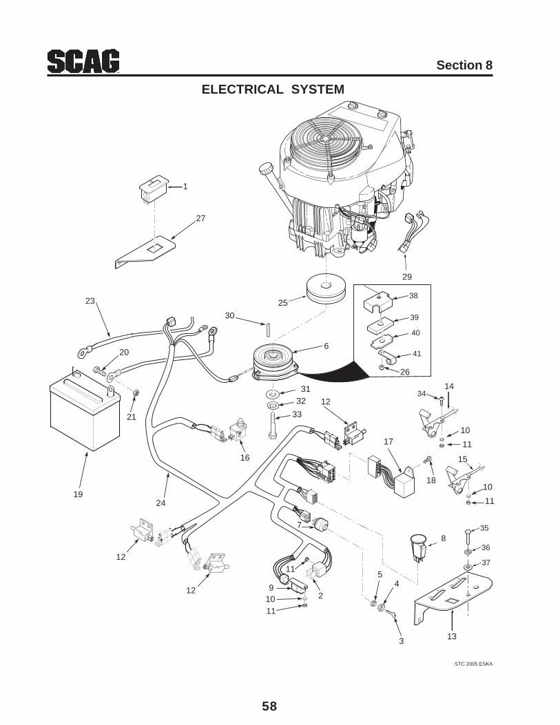
58
Section 8
ELECTRICAL SYSTEM
STC 2005 ESKA
29
30
23
20
21
1924
16
33
3231
12
17
18
14
10
11
10
11
15
8
3
45
91011
2
11
12
12
13
7
6
25
26
38
39
40
41
35
36
37
34
27
1

59
Section 8
1 483355 Hourmeter2 48298 Fuse, 20 amp3 48017-02 Key, Ignition4 48017-04 Nut, Hex 5/8-325 48017-03 Lockwasher, 5/8” Internal6 461660 Electric PTO Clutch GT3.57 48798 Switch, Ignition8 483162 Switch, PTO9 483013 Relay10 04031-01 Lock Washer, #10 External Tooth11 04020-01 Nut, Hex #10-3212 481637 Switch, N/O13 461768 Panel, Instrument14 482032 Choke & Throttle Control - Kawasaki (Qty 2)
481544 Choke Control - Kohler & Honda (Qty 1)15 482032 Throttle Control - Kohler ( Qty 1)
482399 Throttle Control - Honda (Qty 1)16 481638 Switch, Seat17 483029 Module, Interlock18 04010-01 Screw, #10-32 x .5” Phillips Head19 483420 Battery, 300CCA (Not Available Through Scag)20 04001-44 Bolt, Hex Head 1/4-20 x .5”21 04020-02 Nut, Hex 1/4-2022 48029-15 Cable, Battery Black (negative)23 48029-12 Cable, Battery Red (positive)24 483426 Wiring Harness, Main25 483081 Pulley, 5.45 OD x 1.125 Bore26 04021-10 Nut, Elastic Stop 5/16-18 Key27 424112 Mounting Bracket, Hour Meter28 04010-11 Screw, #10-32 x 1.5” Phillips Head29 482543 Adaptor, Wiring Harness (Kawasaki only)
482094 Adaptor, Wiring Harness (Kohler only)482740 Adaptor, Wiring Harness (Honda only)
30 04063-23 Key, 1/4 x 1/4 x 3-1/4”31 04041-28 Flatwasher, 7/16-.469 x 1-3/4” x 1/4”32 04030-05 Lockwasher, 7/16”33 04001-101 Bolt, Hex Head 7/16-20 x 2-1/2” UNF34 04010-12 Screw, #10-32 x 3/4”35 04001-08 Bolt, Hex Head 5/16-18 x 3/4”36 04030-03 Lockwasher, 5/1637 04040-15 Flatwasher, 5/16-.375 x .875 x .08338 423909 Backing Plate39 481716 Rubber Pad, Clutch Stop40 422534 Plate, Backing41 48030-09 Clamp
Ref. PartNo. No. Description
ELECTRICAL SYSTEM
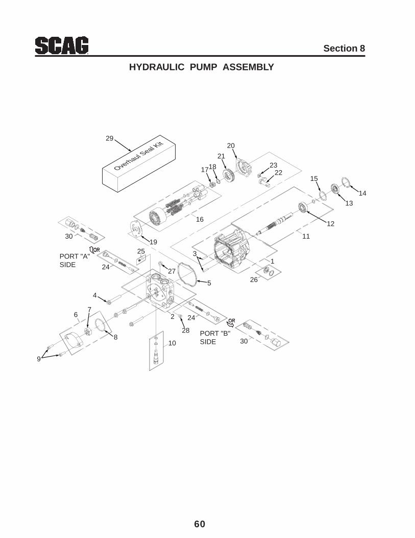
60
Section 8
HYDRAULIC PUMP ASSEMBLY
Overhaul Seal K
it
1
2
3
4
5
67
8
9
10
28
24
30
26
11
12
1314
1522
23
20
21
1817
16
19
27
29
25
30
24
PORT "A"SIDE
PORT "B"SIDE
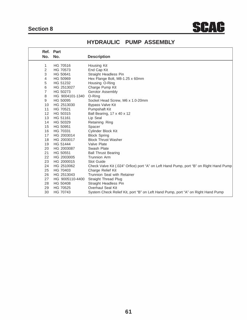
61
Section 8
Ref. PartNo. No. Description
HYDRAULIC PUMP ASSEMBLY
1 HG 70516 Housing Kit2 HG 70573 End Cap Kit3 HG 50641 Straight Headless Pin4 HG 50969 Hex Flange Bolt, M8-1.25 x 60mm5 HG 51232 Housing O-Ring6 HG 2513027 Charge Pump Kit7 HG 50273 Gerotor Assembly
8 HG 9004101-1340 O-Ring9 HG 50095 Socket Head Screw, M6 x 1.0-20mm10 HG 2513030 Bypass Valve Kit11 HG 70521 Pumpshaft Kit12 HG 50315 Ball Bearing, 17 x 40 x 1213 HG 51161 Lip Seal14 HG 50329 Retaining Ring15 HG 50951 Spacer16 HG 70331 Cylinder Block Kit17 HG 2003014 Block Spring18 HG 2003017 Block Thrust Washer19 HG 51444 Valve Plate20 HG 2003087 Swash Plate21 HG 50551 Ball Thrust Bearing22 HG 2003005 Trunnion Arm23 HG 2000015 Slot Guide24 HG 2510062 Check Valve Kit (.024” Orfice) port “A” on Left Hand Pump, port “B” on Right Hand Pump25 HG 70403 Charge Relief Kit26 HG 2513043 Trunnion Seal with Retainer27 HG 9005110-4400 Straight Thread Plug28 HG 50408 Straight Headless Pin29 HG 70525 Overhaul Seal Kit30 HG 70743 System Check Relief Kit, port “B” on Left Hand Pump, port “A” on Right Hand Pump
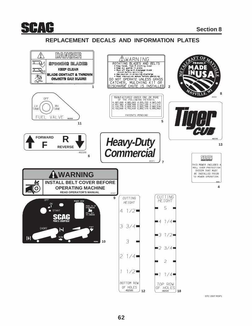
62
Section 8
REPLACEMENT DECALS AND INFORMATION PLATES
1 2
5
8
6
4
9
12
7
48404
STC 2007 RDP1
WARNINGINSTALL BELT COVER BEFORE
OPERATING MACHINEREAD OPERATOR'S MANUAL 483402
482100
FORWARD
REVERSEFR Heavy-Duty
Commercial481971
10
11
13
18
482982
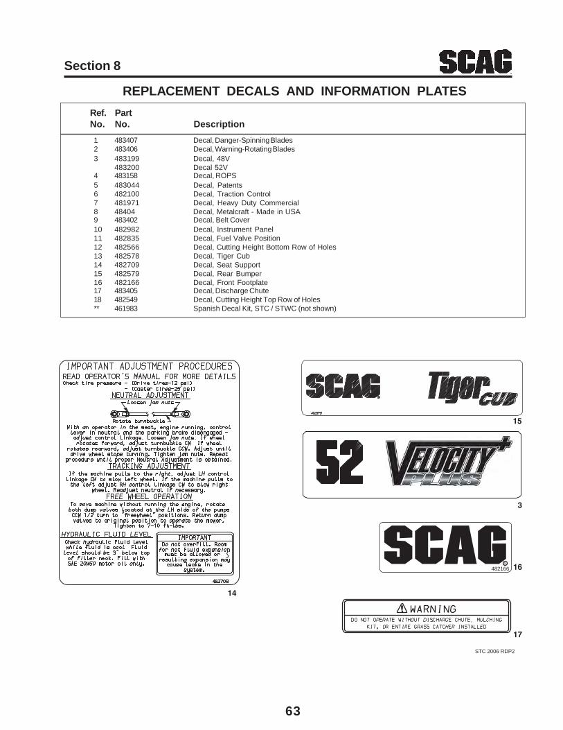
63
Section 8
1 483407 Decal, Danger-Spinning Blades2 483406 Decal, Warning-Rotating Blades3 483199 Decal, 48V
483200 Decal 52V4 483158 Decal, ROPS5 483044 Decal, Patents6 482100 Decal, Traction Control7 481971 Decal, Heavy Duty Commercial8 48404 Decal, Metalcraft - Made in USA9 483402 Decal, Belt Cover10 482982 Decal, Instrument Panel11 482835 Decal, Fuel Valve Position12 482566 Decal, Cutting Height Bottom Row of Holes13 482578 Decal, Tiger Cub14 482709 Decal, Seat Support15 482579 Decal, Rear Bumper16 482166 Decal, Front Footplate17 483405 Decal, Discharge Chute18 482549 Decal, Cutting Height Top Row of Holes** 461983 Spanish Decal Kit, STC / STWC (not shown)
Ref. PartNo. No. Description
REPLACEMENT DECALS AND INFORMATION PLATES
STC 2006 RDP2
14
15
R
16
17
482166
3
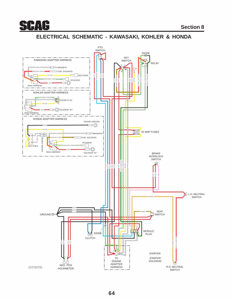
64
Section 8
ELECTRICAL SCHEMATIC - KAWASAKI, KOHLER & HONDA
RELAY
MODULEPLUG
PTOSWITCH
KEYSWITCH
TOENGINE
ADAPTERHARNESS
CLUTCH
NEG POSHOURMETER
STARTERSOLENOID
STARTER
GROUND
R.H. NEUTRALSWITCH
20 AMP FUSES
BRAKEINTERLOCK
SWITCH
SEATSWITCH
L.H. NEUTRALSWITCH
DIODE
DIODE
KAWASAKI ADAPTER HARNESS
KOHLER ADAPTER HARNESS
HONDA ADAPTER HARNESS
MAGNETO
FUEL SOLENOID
RECTIFIER
SOLENOID
SOLENOID "B+"
ENGINE PLUG
SOLENOID
SOLENOID "B+"
MAGNETO
FUEL SOLENOID
ENGINE GROUND
MAIN HARNESS
RECTIFIER
EN
GIN
E S
TATO
R
MAIN HARNESS
MAIN HARNESS
PIN
K
RE
D
GR
N W
/BLK
ST
RIP
E
WH
ITE
BLA
CK
LIGH
T B
LUE
OR
AN
GE
BROWN
RE
D
BLU
E
LIGH
T B
LUE
RE
D W
/YE
L ST
RIP
E
YE
LLOW
RE
D
RE
D
RE
D
RE
D
RE
D
RE
D W
/YE
L ST
RIP
E
BLU
E
RE
D
RE
D
RE
D
GR
N W
/BLK
ST
RIP
E
YE
LLOW
WH
ITE
BLA
CK
GR
N W
/WH
T S
TR
IPE
GR
EE
N
GR
EE
NG
RN
W/W
HT
ST
RIP
E
RE
D
BLA
CK
BLA
CK
RE
D
BLACK
BLACK
BLACK
ORANGE
RE
D W
/WH
T S
TR
IPE
WHITE
RED
RED W/YEL STRIPE
YELLOW
GRN W/WHT STRIPE
WHITE
RED
YELLOW
GRN W/WHT STRIPE
WHITE
RED
RED W/YEL STRIPE
YELLOW
GRN W/WHT STRIPE
BLACK
GR
AY
STC Electrical SchematicSerial No. 7630001 & Higher

LIMITED WARRANTY - COMMERCIAL EQUIPMENTAny part of the Scag commercial mower manufactured by Scag Power Equipment and found, in the reasonable judgmentof Scag, to be defective in materials or workmanship, will be repaired or replaced by an Authorized Scag Service Dealerwithout charge for parts and labor during the periods specified below. This warranty is limited to the original purchaserand is not transferable. Proof of purchase will be required by the dealer to substantiate any warranty claims. All warrantywork must be performed by an Authorized Scag Service Dealer.
This warranty is limited to the following specified periods from the date of the original retail purchase for defects inmaterials or workmanship:
* Wear items including drive belts, blades, hydraulic hoses and tires are warranted for ninety (90) days.* Batteries are covered for ninety (90) days.* Frame and structural components including oil reservoir and oil coolers are warranted for 2 years (Parts and labor).* Cutter decks are warranted against cracking for a period of three (3) years. (Parts and labor 1st and 2nd year; Parts only 3rd year) The repair or replacement of the cutter deck will be at the option of Scag Power Equipment. We reserve the right to request components for evaluation. This warranty does not cover any mower that has been subject to misuse, neglect, negligence, or accident, or that has been operated in any way contrary to the operating instructions as specified in the Operator’s Manual.* Engines and electric starters are covered by the engine manufacturer’s warranty period.* Major drive system components are warranted for two (2) years by Scag Power Equipment. (Parts and labor) (Two year warranty exclude fittings, hoses, drive belts). The repair or replacement of the hydraulic pump or hydraulic motor will be at the option of Scag Power Equipment. This warranty does not cover any mower that has been subject to misuse, neglect, negligence, or accident, or that has been operated in any way contrary to the operating instructions as specified in the Operator’s Manual.* Electric clutches have a Limited Warranty for 2 year (Parts and labor).* Spindle Assemblies have a Limited Warranty for three years (Parts and labor 1st year and 2nd; Parts only 3rd year).* Any Scag product used for rental purposes is covered by a 90 day warranty.
The Scag mower, including any defective part must be returned to an Authorized Scag Service Dealer within the warrantyperiod. The expense of delivering the mower to the dealer for warranty work and the expense of returning it to the ownerafter repair will be paid for by the owner. Scag’s responsibility is limited to making the required repairs and no claim ofbreach of warranty shall be cause for cancellation or rescission of the contract of sale of any Scag mower.
This warranty does not cover any mower that has been subject to misuse, neglect, negligence, or accident, or that hasbeen operated in any way contrary to the operating instructions as specified in the Operator’s Manual. The warrantydoes not apply to any damage to the mower that is the result of improper maintenance, or to any mower or parts that havenot been assembled or installed as specified in the Operator’s Manual and Assembly Manual. The warranty does notcover any mower that has been altered or modified, changing performance or durability. In addition, the warranty does notextend to repairs made necessary by normal wear, or by the use of parts or accessories which, in the reasonable judgmentof Scag, are either incompatible with the Scag mower or adversely affect its operation, performance or durability.
Scag Power Equipment reserves the right to change or improve the design of any mower without assuming any obliga-tion to modify any mower previously manufactured. All other implied warranties are limited in duration to the two (2) yearwarranty period or ninety (90) days for mowers used for rental purpose. Accordingly, any such implied warrantiesincluding merchantability, fitness for a particular purpose, or otherwise, are disclaimed in their entirety after the expirationof the appropriate two year or ninety day warranty period. Scag’s obligation under this warranty is strictly and exclusivelylimited to the repair or replacement of defective parts and Scag does not assume or authorize anyone to assume for themany other obligation. Some states do not allow limitations on how long an implied warranty lasts, so the above limitationmay not apply to you.
Scag assumes no responsibility for incidental, consequential or other damages including, but not limited to, expense forgasoline, expense of delivering the mower to an Authorized Scag Service Dealer and expense of returning it to the owner,mechanic’s travel time, telephone or telegram charges, rental of a like product during the time warranty repairs are beingperformed, travel, loss or damage to personal property, loss of revenue, loss of use of the mower, loss of time or inconve-nience. Some states do not allow the exclusion or limitation of incidental or consequential damages, so the above limita-tion or exclusion may not apply to you. This warranty gives you specific legal rights, and you may also have other rightswhich vary from state to state.
GARANTÍA LIMITADA - EQUIPO COMERCIALToda pieza del cortacésped comercial Scag fabricada por Scag Power Equipment que, según criterio razonable de Scag, presentemateriales o mano de obra defectuosos será reparada o reemplazada por un distribuidor autorizado Scag sin cargo por las piezas nimano de obra durante los períodos especificados abajo. Esta garantía se limita al comprador original y no es transferible. Para acceder acualquier reclamo de garantía, el distribuidor requerirá el comprobante de compra. Todo trabajo bajo garantía debe realizarlo undistribuidor autorizado Scag.
Con respecto a materiales o mano de obra defectuosos, esta garantía se limita a los siguientes períodos especificados a partir de la fechade compra original:
* Los artículos desgastables, incluyendo correas de transmisión, cuchillas, mangueras hidráulicas y llantas, están garantizadospor noventa (90) días.
* Las baterías están garantizadas por noventa (90) días.* El bastidor y los componentes estructurales, incluyendo el depósito de aceite y los enfriadores de aceite, tienen una garantía
de 2 años (Piezas y mano de obra).* Las plataformas de corte están garantizadas contra grietas por un período de tres (3) años. (Piezas y mano de obra, primer y
segundo año; piezas solamente, tercer año). La reparación o el reemplazo de la plataforma de corte estarán sujetos adiscreción de Scag Power Equipment. Nos reservamos el derecho de solicitar componentes para su evaluación. Esta garantíano cubre ningún cortacésped que haya sido sometido a uso indebido, descuido, negligencia o accidente, o que se hayaoperado de manera distinta a la especificada en el manual del operador.
* Los motores eléctricos y los arrancadores están cubiertos por el período de garantía del fabricante de motor.* Los componentes principales del sistema de transmisión están garantizados por Scag Power Equipment por dos (2) años.
(Piezas y mano de obra) (La garantía de dos años no incluye las conexiones, mangueras, las correas de transmisión). Lareparación o el reemplazo de la bomba hidráulica o el motor hidráulico estarán sujetos a discreción de Scag Power Equipment.Esta garantía no cubre ningún cortacésped que haya sido sometido a uso indebido, descuido, negligencia o accidente, o que sehaya operado de manera distinta a la especificada en el manual del operador.
* Los embragues eléctricos tienen una Garantía limitada de 2 años (Piezas y mano de obra).* Los ensambles del eje tienen una Garantía limitada de 3 años (Piezas y mano de obra, primer y segundo año; piezas
solamente, tercer año).* Cualquier producto Scag que se utilice para alquiler está cubierto por una garantía de 90 días.
El cortacésped Scag, incluida cualquier pieza defectuosa, debe ser llevado a un distribuidor autorizado de Scag dentro del período degarantía. Los gastos incurridos en la entrega del cortacésped al distribuidor para que se realice el trabajo bajo garantía, así como losgastos de devolución del cortacésped al propietario después de la reparación, estarán a cargo del propietario. La responsabilidad de Scagse limita a la realización de las reparaciones requeridas y ninguna reclamación por incumplimiento de las obligaciones de garantía serácausa de cancelación o revocación del contrato de venta del cortacésped Scag.
Esta garantía no cubre ningún cortacésped que haya sido sometido a uso indebido, descuido, negligencia o accidente, o quese haya operado de manera distinta a la especificada en el manual del operador. La garantía no será de aplicación en ningún casode daño ocasionado al cortacésped como consecuencia de mantenimiento inadecuado o a cualquier cortacésped o piezas que no se hayanensamblado o instalado de acuerdo con las especificaciones del manual del operador o el manual de montaje. La garantía no cubre ningúncortacésped que haya sufrido alteraciones o modificaciones que hayan afectado su funcionamiento o durabilidad. Asimismo, la garantíano se extiende a reparaciones necesarias por el desgaste normal o por el uso de piezas o accesorios que, según criterio razonable de Scag,sean incompatibles con el cortacésped Scag o afecten la operación, funcionamiento o durabilidad de éste.
Scag Power Equipment se reserva el derecho de modificar o mejorar el diseño de cualquier cortacésped sin tener por elloobligación alguna de modificar cualquier cortacésped fabricado con anterioridad. Cualquier otra garantía implícita se limita a unperíodo de garantía de dos (2) años o noventa (90) días en el caso de cortacéspedes destinados a alquiler. Por consiguiente, se rechaza ensu totalidad cualquier garantía implícita, incluidas las garantías de comerciabilidad, adecuación para un fin determinado, o de otro tipo,después de la finalización del correspondiente período de garantía de dos años o noventa días. La obligación de Scag en virtud de lapresente garantía se limita estricta y exclusivamente a la reparación o el reemplazo de piezas defectuosas, y Scag no asume ni autoriza aningún otro a asumir en su lugar ninguna otra obligación. La limitación antes mencionada no será de aplicación en aquellos estados en losque no esté permitida la limitación del período de validez de una garantía implícita.
Scag no asume responsabilidad alguna por daños incidentales, consecuentes ni de cualquier otro tipo, incluyendo, pero sin limitarse a,gasto de gasolina, gasto de entrega del cortacésped a un distribuidor autorizado Scag y gasto de su devolución al propietario, tiempo deviaje del mecánico, cargos por comunicaciones telefónicas o telegramas, alquiler de un producto similar durante el período en que sellevan a cabo las reparaciones bajo garantía, viajes, pérdida o daño de bienes personales, lucro cesante, daños ocasionados por lapérdida del uso del cortacésped, daños por la pérdida de tiempo o cualquier otro inconveniente. La limitación o exclusiónantes mencionada no será de aplicación en aquellos estados en los que no esté permitida la exclusión o limitación dedaños incidentales o consecuentes. La presente garantía le otorga derechos legales específicos, aparte de los derechosde los que usted goza, según el estado.
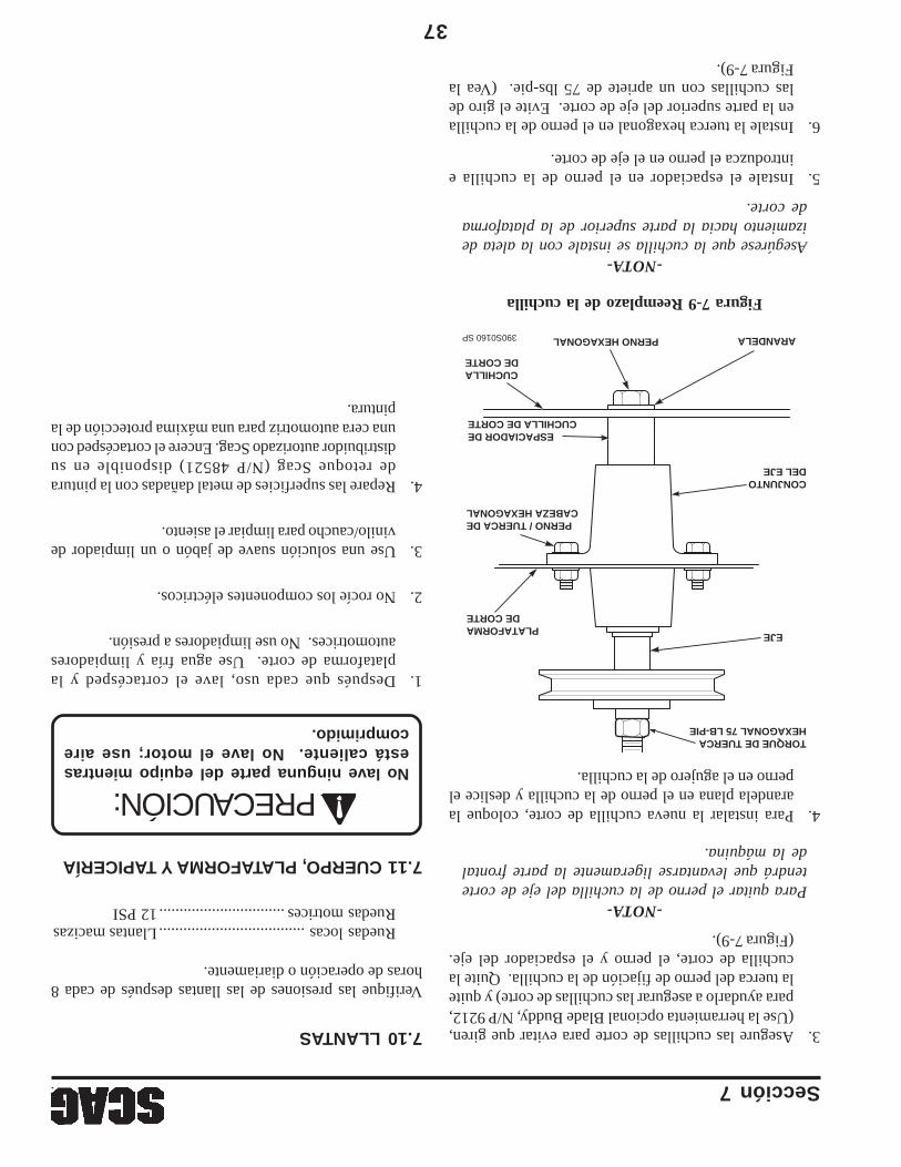
Sección 7
37
Figura 7-9 Reemplazo de la cuchilla
7.10 LLANTAS
Verifique las presiones de las llantas después de cada 8horas de operación o diariamente.
Ruedas locas....................................Llantas macizasRuedas motrices...............................12 PSI
390S0160 SP
PLATAFORMADE CORTE
TORQUE DE TUERCAHEXAGONAL 75 LB-PIE
EJE
CONJUNTODEL EJE
ARANDELAPERNO HEXAGONAL
CUCHILLADE CORTE
PERNO / TUERCA DECABEZA HEXAGONAL
ESPACIADOR DECUCHILLA DE CORTE
3.Asegure las cuchillas de corte para evitar que giren,(Use la herramienta opcional Blade Buddy, N/P 9212,para ayudarlo a asegurar las cuchillas de corte) y quitela tuerca del perno de fijación de la cuchilla. Quite lacuchilla de corte, el perno y el espaciador del eje.(Figura 7-9).
-NOTA-Para quitar el perno de la cuchilla del eje de cortetendrá que levantarse ligeramente la parte frontalde la máquina.
4.Para instalar la nueva cuchilla de corte, coloque laarandela plana en el perno de la cuchilla y deslice elperno en el agujero de la cuchilla.
-NOTA-Asegúrese que la cuchilla se instale con la aleta deizamiento hacia la parte superior de la plataformade corte.
5.Instale el espaciador en el perno de la cuchilla eintroduzca el perno en el eje de corte.
6.Instale la tuerca hexagonal en el perno de la cuchillaen la parte superior del eje de corte. Evite el giro delas cuchillas con un apriete de 75 lbs-pie. (Vea laFigura 7-9).
7.11 CUERPO, PLATAFORMA Y TAPICERÍA
No lave ninguna parte del equipo mientrasestá caliente. No lave el motor; use airecomprimido.
1.Después que cada uso, lave el cortacésped y laplataforma de corte. Use agua fría y limpiadoresautomotrices. No use limpiadores a presión.
2.No rocíe los componentes eléctricos.
3.Use una solución suave de jabón o un limpiador devinilo/caucho para limpiar el asiento.
4.Repare las superficies de metal dañadas con la pinturade retoque Scag (N/P 48521) disponible en sudistribuidor autorizado Scag. Encere el cortacésped conuna cera automotriz para una máxima protección de lapintura.
PRECAUCIÓN:
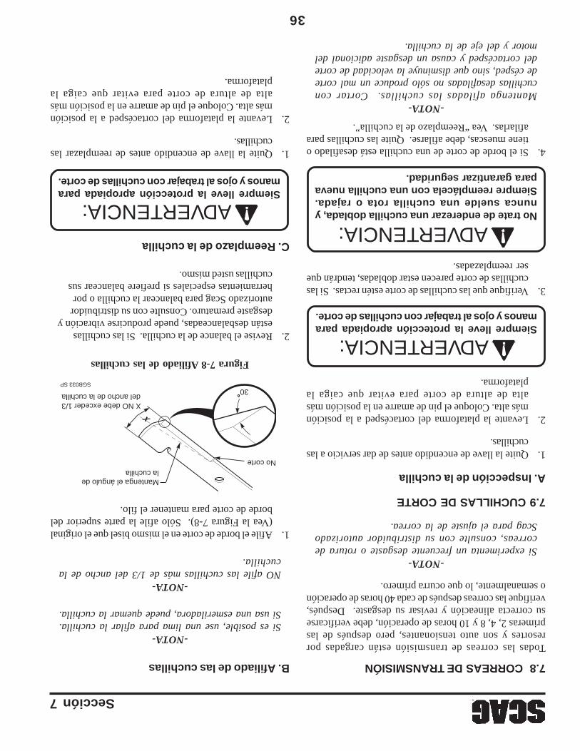
36
Sección 7
2.Revise el balance de la cuchilla. Si las cuchillasestán desbalanceadas, puede producirse vibración ydesgaste prematuro. Consulte con su distribuidorautorizado Scag para balancear la cuchilla o porherramientas especiales si prefiere balancear suscuchillas usted mismo.
C. Reemplazo de la cuchilla
1.Quite la llave de encendido antes de reemplazar lascuchillas.
2.Levante la plataforma del cortacésped a la posiciónmás alta. Coloque el pin de amarre en la posición másalta de altura de corte para evitar que caiga laplataforma.
Figura 7-8 Afiliado de las cuchillas
7.8 CORREAS DE TRANSMISIÓN
Todas las correas de transmisión están cargadas porresortes y son auto tensionantes, pero después de lasprimeras 2, 4, 8 y 10 horas de operación, debe verificarsesu correcta alineación y revisar su desgaste. Después,verifique las correas después de cada 40 horas de operacióno semanalmente, lo que ocurra primero.
-NOTA-Si experimenta un frecuente desgaste o rotura decorreas, consulte con su distribuidor autorizadoScag para el ajuste de la correa.
7.9 CUCHILLAS DE CORTE
A. Inspección de la cuchilla
1.Quite la llave de encendido antes de dar servicio a lascuchillas.
2.Levante la plataforma del cortacésped a la posiciónmás alta. Coloque el pin de amarre en la posición másalta de altura de corte para evitar que caiga laplataforma.
Siempre lleve la protección apropiada paramanos y ojos al trabajar con cuchillas de corte.
4.Si el borde de corte de una cuchilla está desafilado otiene muescas, debe afilarse. Quite las cuchillas paraafilarlas. Vea “Reemplazo de la cuchilla”.
-NOTA-Mantenga afiladas las cuchillas. Cortar concuchillas desafiladas no sólo produce un mal cortede césped, sino que disminuye la velocidad de cortedel cortacésped y causa un desgaste adicional delmotor y del eje de la cuchilla.
No trate de enderezar una cuchilla doblada, ynunca suelde una cuchilla rota o rajada.Siempre reemplácela con una cuchilla nuevapara garantizar seguridad.
B. Afiliado de las cuchillas
-NOTA-Si es posible, use una lima para afilar la cuchilla.Si usa una esmeriladora, puede quemar la cuchilla.
-NOTA-NO afile las cuchillas más de 1/3 del ancho de lacuchilla.
1.Afile el borde de corte en el mismo bisel que el original(Vea la Figura 7-8). Sólo afile la parte superior delborde de corte para mantener el filo.
3.Verifique que las cuchillas de corte estén rectas. Si lascuchillas de corte parecen estar dobladas, tendrán queser reemplazadas.
Siempre lleve la protección apropiada paramanos y ojos al trabajar con cuchillas de corte.
SGB033 SP
Mantenga el ángulo de la cuchilla
No corte
X NO debe exceder 1/3del ancho de la cuchilla
X
30
ADVERTENCIA:
ADVERTENCIA:ADVERTENCIA:
Sección 7
35
Las baterías plomo-ácido producen gasesinflamables y explosivos. Para evitar lesionespersonales al revisar, probar o cargarbaterías, NO USE materiales que produzcanhumo cerca de las baterías. Mantenga losarcos, las chispas y las llamas lejos de lasbaterías. Proporcione ventilación apropiaday use gafas de seguridad.
Los postes de la batería, los terminales ylos accesorios relacionados contienenplomo y compuestos de plomo; el Estadode California identifica a estas sustanciasquímicas como causantes de cáncer y dañoa los órganos reproductivos. Lávese lasmanos después de manipular baterías.
7.7 BATERÍA
El líquido de la batería contiene ácido sulfúricoque es TÓXICO y puede causar GRAVESQUEMADURAS QUÍMICAS. Evite el contactodel líquido con los ojos, la piel, o con la ropa.Use equipo de protección apropiado cuandomanipule baterías. NO INCLINE ningunabatería más de 45° en ninguna dirección. Siocurre contacto con el líquido, siga primerolas sugerencias de primeros auxilios.
PRIMEROS AUXILIOS PARA ELECTROLITODE BATERÍA
CONTACTO EXTERNO — Enjuague conagua.OJOS — Enjuague con agua al menosdurante 15 minutos y obtenga atenciónmédica inmediatamente.INTERNO — Beba grandes cantidades deagua. Continúe con leche de magnesia,huevos batidos, o aceite vegetal. Obtengaatención médica inmediatamente. En casode contacto interno, NO PROPORCIONElíquidos que induzcan al vómito.
A. Carga de la batería
Consulte el manual del cargador de batería parainstrucciones específicas.
Bajo condiciones normales el alternador del motor notendrá problemas para mantener la carga de la batería.Si la batería se ha descargado completamente por unperíodo largo de tiempo, el alternador puede no ser capazde recargar la batería, y se necesitará un cargador debaterías.
NO cargue una batería congelada. Puede estallar ycausar lesiones. Permita que la batería se entibie antesde conectar un cargador.
Siempre que sea posible, quite la batería del cortacéspedantes de cargarla y asegúrese de que el electrolito cubrelas placas en todas las celdas.
LAS BATERÍAS PRODUCEN GASESEXPLOSIVOS. Cargue la batería en unespacio bien ventilado de modo que sepuede disipar los gases producidos durantela carga.
Las tasas de carga entre 3 y 50 amperios son satisfactoriassi no provocan excesivos gases, si no arrojan demasiadoelectrolito o si la batería no está muy caliente (encima de125° F). Si se produce derrame de electrolito o excesivaproducción de gas, o si la temperatura excede 52°C (125°F),la tasa de carga debe reducirse o detenerse temporalmentepara permitir el enfriamiento.
B. Arranque por puente
1.La batería auxiliar de arranque debe ser de 12 voltios.Si se usa un vehículo para el arranque por puente, debetener un sistema de tierra negativo.
2.Cuando conecte los cables del puente, conecte el cablepositivo al poste positivo de la batería, y luego el cablenegativo al poste negativo de la batería.
ADVERTENCIA:
ADVERTENCIA:
ADVERTENCIA:
ADVERTENCIA:
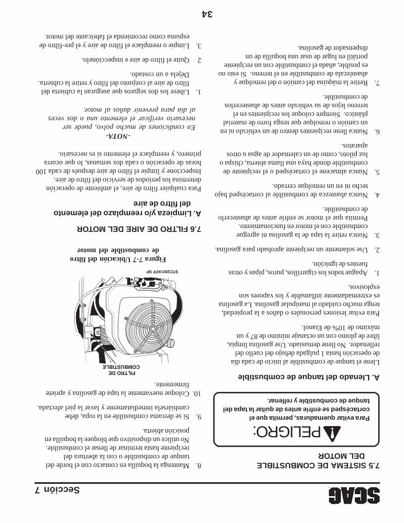
34
Sección 7
Figura 7-7 Ubicación del filtrode combustible del motor
7.6 FILTRO DE AIRE DEL MOTOR
A. Limpieza y/o reemplazo del elementodel filtro de aire
Para cualquier filtro de aire, el ambiente de operacióndetermina los períodos de servicio del filtro de aire.Inspeccione y limpie el filtro de aire después de cada 100horas de operación o cada dos semanas, lo que ocurraprimero, y reemplace el elemento si es necesario.
-NOTA-En condiciones de mucho polvo, puede sernecesario verificar el elemento una o dos vecesal día para prevenir daños al motor.
1.Libere los dos seguros que aseguran la cubierta delfiltro de aire al conjunto del filtro y retire la cubierta.Déjela a un costado.
2Quite el filtro de aire e inspecciónelo.
3.Limpie o reemplace el filtro de aire y el pre-filtro deespuma como recomienda el fabricante del motor.
FILTRO DE COMBUSTIBLE
STC2001KFF SP
A. Llenado del tanque de combustible
Llene el tanque de combustible al inicio de cada díade operación hasta 1 pulgada debajo del cuello delrellenador. No llene demasiado. Use gasolina limpia,libre de plomo con un octanaje mínimo de 87 y unmáximo de 10% de Etanol.
Para evitar lesiones personales o daños a la propiedad,tenga mucho cuidado al manipular gasolina. La gasolinaes extremadamente inflamable y los vapores sonexplosivos.
1.Apague todos los cigarrillos, puros, pipas y otrasfuentes de ignición.
2.Use solamente un recipiente aprobado para gasolina.
3.Nunca retire la tapa de la gasolina ni agreguecombustible con el motor en funcionamiento.Permita que el motor se enfríe antes de abastecerlode combustible.
4.Nunca abastezca de combustible al cortacésped bajotecho ni en un remolque cerrado.
5.Nunca almacene el cortacésped o el recipiente decombustible donde haya una llama abierta, chispa oluz piloto, como de un calentador de agua u otrosaparatos.
6.Nunca llene recipientes dentro de un vehículo ni enun camión o remolque que tenga forro de materialplástico. Siempre coloque los recipientes en elterreno lejos de su vehículo antes de abastecerlosde combustible.
7.Retire la máquina del camión o del remolque yabastézcala de combustible en el terreno. Si esto noes posible, añada el combustible con un recipienteportátil en lugar de usar una boquilla de undispensador de gasolina.
7.5 SISTEMA DE COMBUSTIBLEDEL MOTOR
Para evitar quemaduras, permita que elcortacésped se enfríe antes de quitar la tapa deltanque de combustible y rellenar.
8.Mantenga la boquilla en contacto con el borde deltanque de combustible o con la abertura delrecipiente hasta terminar de llenar el combustible.No utilice un dispositivo que bloquee la boquilla enposición abierta.
9.Si se derrama combustible en la ropa, debecambiársela inmediatamente y lavar la piel afectada.
10.Coloque nuevamente la tapa de gasolina y aprietefirmemente.
PELIGRO:
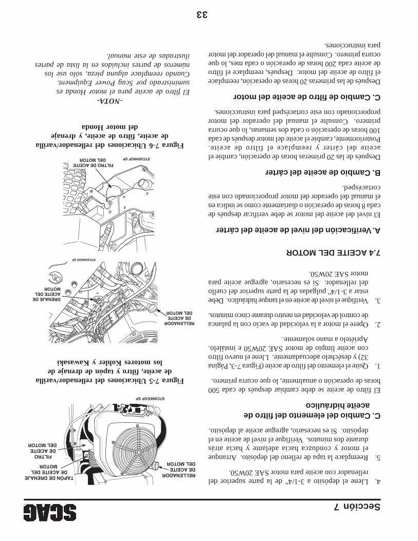
Sección 7
33
-NOTA-El filtro de aceite para el motor Honda essuministrado por Scag Power Equipment.Cuando reemplace alguna pieza, sólo use losnúmeros de partes incluidos en la lista de partesilustradas de este manual.
Figura 7-5 Ubicaciones del rellenador/varillade aceite, filtro y tapón de drenaje de
los motores Kohler y Kawasaki
4.Llene el depósito a 3-1/4" de la parte superior delrellenador con aceite para motor SAE 20W50.
5.Reemplace la tapa de relleno del depósito. Arranqueel motor y conduzca hacia adelante y hacia atrásdurante dos minutos. Verifique el nivel de aceite en eldepósito. Si es necesario, agregue aceite al depósito.
C. Cambio del elemento del filtro deaceite hidráulico
El filtro de aceite se debe cambiar después de cada 500horas de operación o anualmente, lo que ocurra primero.
1.Quite el elemento del filtro de aceite (Figura 7-3, Página32) y deséchelo adecuadamente. Llene el nuevo filtrocon aceite limpio de motor SAE 20W50 e instálelo.Apriételo a mano solamente.
2.Opere el motor a la velocidad de vacío con la palancade control de velocidad en neutro durante cinco minutos.
3.Verifique el nivel de aceite en el tanque hidráulico. Debeestar a 3-1/4" pulgadas de la parte superior del cuellodel rellenador. Si es necesario, agregue aceite paramotor SAE 20W50.
7.4 ACEITE DEL MOTOR
A. Verificación del nivel de aceite del cárter
El nivel del aceite del motor se debe verificar después decada 8 horas de operación o diariamente como se indica enel manual del operador del motor proporcionado con estecortacésped.
B. Cambio de aceite del cárter
Después de las 20 primeras horas de operación, cambie elaceite del cárter y reemplace el filtro de aceite.Posteriormente, cambie el aceite del motor después de cada100 horas de operación o cada dos semanas, lo que ocurraprimero. Consulte el manual del operador del motorproporcionado con este cortacésped para instrucciones.
C. Cambio de filtro de aceite del motor
Después de las primeras 20 horas de operación, reemplaceel filtro de aceite del motor. Después, reemplace el filtrode aceite cada 200 horas de operación o cada mes, lo queocurra primero. Consulte el manual del operador del motorpara instrucciones.
RELLENADORDE ACEITEDEL MOTOR
FILTRO DE ACEITE DEL MOTOR
TAPÓN DE DRENAJE DE ACEITE DEL
MOTOR
STC99KEOP SP
RELLENADOR DE ACEITE DEL MOTOR
DRENAJE DE ACEITE DEL MOTOR
STC05HNOD SP
Figura 7-6 Ubicaciones del rellenador/varillade aceite, filtro de aceite, y drenaje
del motor Honda
FILTRO DE ACEITE DEL MOTOR STC05HNOF SP
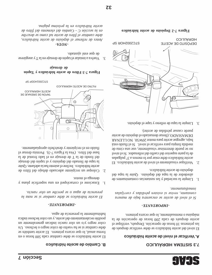
32
Sección 7
Figura 7-2 Depósito de aceite hidráulico
7.3 SISTEMA HIDRÁULICO
A. Verificar el nivel de aceite hidráulico
El nivel del aceite hidráulico se debe verificar después delas primeras 10 horas de operación. Después, verifique elaceite después de cada 200 horas de operación de lamáquina o mensualmente, lo que ocurra primero.
-IMPORTANTE-
Si el nivel de aceite se encuentra bajo de maneraconstante, revise si existen pérdidas y corríjalasinmediatamente.
1.Limpie la suciedad y las sustancias contaminantes dealrededor de la tapa del depósito. Quite la tapa deldepósito de aceite hidráulico.
2.Verifique visualmente el nivel de aceite hidráulico. Elaceite hidráulico debe estar por lo menos a 3" pulgadasde la parte superior del cuello del rellenador. Si el nivelno se puede determinar visualmente, use una cinta demedida limpia para verificar el nivel. Si el fluido estábajo, agregue aceite para motor 20W50. NO LLENARDEMASIADO; (llenar demasiado el depósito de aceitepuede causar pérdidas de aceite).
3.Limpie la tapa de relleno y tape el depósito.
B. Cambio de aceite hidráulico
El aceite hidráulico se debe cambiar cada 500 horas o enforma anual, lo que ocurra primero. El aceite también sedebe cambiar si se ha vuelto de color negro o lechoso. Uncolor negro y/o un olor rancio indican generalmente unposible recalentamiento del aceite, y un color lechoso indicahabitualmente la presencia de agua.
-IMPORTANTE-
El aceite hidráulico se debe cambiar si se nota lapresencia de agua o se percibe un olor rancio.
1.Estacione el cortacésped en una superficie plana ydetenga el motor.
2.Coloque un recipiente adecuado debajo del filtro deaceite hidráulico. Incline el asiento hacia adelante. Quitela tapa de llenado del depósito y el tapón del drenajedel fondo de la T de drenaje en el lado frontal de labase del filtro. (Vea la Figura 7-3). Permita drenar elfluido en el recipiente y deséchelo apropiadamente.
Figura 7-3 Filtro de aceite hidráulico y Tapónde drenaje
3.Vuelva a instalar el tapón de drenaje en la T y asegúresede que esté ajustado.
-NOTA-Antes de rellenar el depósito de aceite hidráulico,debe cambiar el filtro de aceite tal como se describeen la sección C - Cambio del elemento del filtro deaceite hidráulico en la próxima página.
FILTRO DE ACEITE HIDRÁULICO
TAPÓN DE DRENAJE DE ACEITE HIDRÁULICO
STC2001HODP SP
DEPÓSITO DE ACEITE HIDRÁULICO
STC2002HOR SP
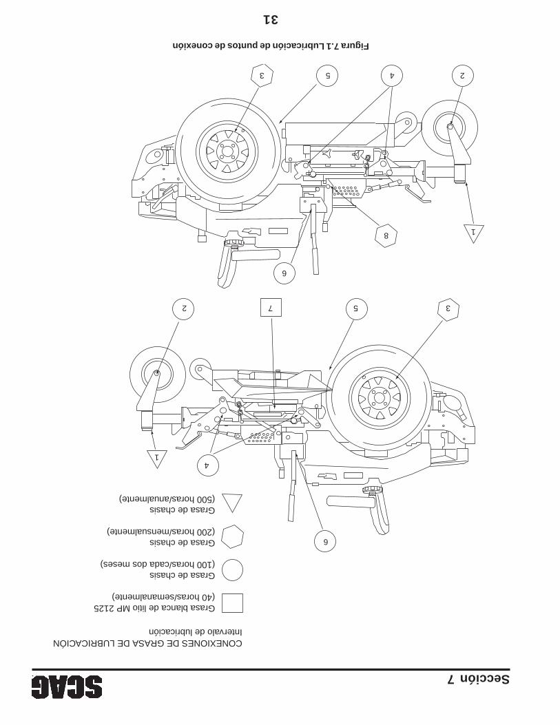
Sección 7
31
Figura 7.1 Lubricación de puntos de conexión
CONEXIONES DE GRASA DE LUBRICACIÓNIntervalo de lubricación
Grasa blanca de litio MP 2125(40 horas/semanalmente)
Grasa de chasis(100 horas/cada dos meses)
Grasa de chasis(200 horas/mensualmente)
Grasa de chasis(500 horas/anualmente)
3 5 4 2
18
6
3572
4
6
1
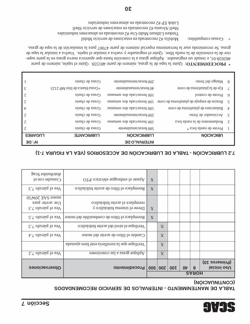
30
Sección 7
7.2 LUBRICACIÓN - TABLA DE LUBRICACIÓN DE ACCESORIOS (VEA LA FIGURA 7-1)
INTERVALO DENº. DE
UBICACIÓNLUBRICACIÓNLUBRICANTELUGARES
1Pivote de rueda loca *500 horas/anualmenteGrasa de chasis2
2Rodamientos de la rueda loca100 horas/cada dos semanasGrasa de chasis2
3Accionador de freno200 horas/mensualmenteGrasa de chasis2
4Balancines de plataforma de corte100 horas/cada dos semanasGrasa de chasis4
5Brazos de empuje de plataforma de corte100 horas/cada dos semanasGrasa de chasis2
6Pivote de control100 horas/cada dos semanasGrasa de chasis2
7Eje de la plataforma de corte40 horas/semanalmente+Grasa blanca de litio MP 21253
8Mango del freno200 horas/mensualmenteGrasa de chasis1
* PROCEDIMIENTO: Quite la tapa de la grasa, número de parte 481559. Quite el tapón, número de parte482028-01, e instale un engrasador. Aplique grasa a la conexión hasta que aparezca nueva grasa en la parte supe-rior de la extensión de la rueda libre. Quite el engrasador y vuelva a instalar el tapón. Vuelva a instalar la tapa degrasa. Se recomienda usar la herramienta especial número de parte 47007 para la instalación de la tapa de grasa.
+Grasas compatibles:Mobilix #2 encontrada en estaciones de servicio MobilTimken Lithium Multi-Use #2 encontrada en almacenes industrialesShell Alvania #2 encontrada en estaciones de servicio ShellLidok EP #2 encontrada en almacenes industriales
TABLA DE MANTENIMIENTO - INTERVALOS DE SERVICIO RECOMENDADOS(CONTINUACIÓN)
HORASUso inicial840100200500ProcedimientoObservaciones(Primeros 10)
XAplique grasa a las conexionesVea el párrafo 7.2
XVerifique que la tornillería esté bien ajustada
XCambie el filtro de aceite del motorVea el párrafo 7.4
XVerifique el nivel del aceite hidráulicoVea el párrafo 7.3
XReemplace el filtro de combustible del motorVea el párrafo 7.5
XDrene el sistema hidráulico yVea el párrafo 7.3reemplace el aceite hidráulicoUse aceite para
motor SAE 20W50
XReemplace el filtro de aceite hidráulicoVea el párrafo 7.3
XAjuste el embrague eléctrico PTOConsulte con eldistribuidor Scag
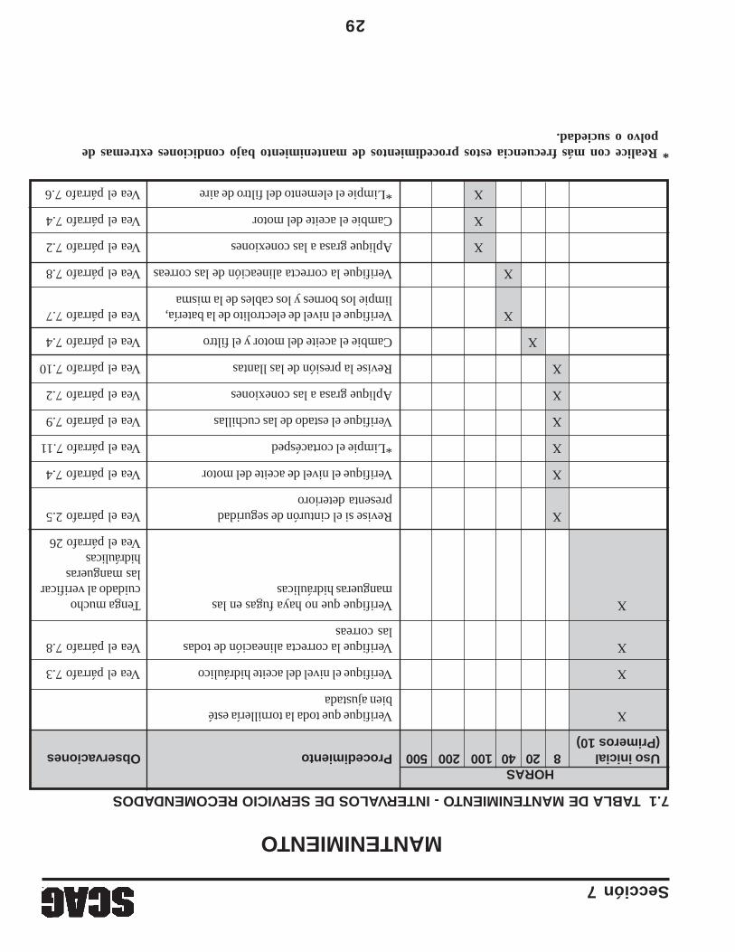
Sección 7
29
7.1 TABLA DE MANTENIMIENTO - INTERVALOS DE SERVICIO RECOMENDADOS
* Realice con más frecuencia estos procedimientos de mantenimiento bajo condiciones extremas depolvo o suciedad.
MANTENIMIENTO
HORASUso inicial82040100200500ProcedimientoObservaciones(Primeros 10)
XVerifique que toda la tornillería estébien ajustada
XVerifique el nivel del aceite hidráulicoVea el párrafo 7.3
XVerifique la correcta alineación de todasVea el párrafo 7.8las correas
XVerifique que no haya fugas en lasTenga muchomangueras hidráulicascuidado al verificar
las manguerashidráulicasVea el párrafo 26
XRevise si el cinturón de seguridadVea el párrafo 2.5presenta deterioro
XVerifique el nivel de aceite del motorVea el párrafo 7.4
X*Limpie el cortacéspedVea el párrafo 7.11
XVerifique el estado de las cuchillasVea el párrafo 7.9
XAplique grasa a las conexionesVea el párrafo 7.2
XRevise la presión de las llantasVea el párrafo 7.10
XCambie el aceite del motor y el filtroVea el párrafo 7.4
XVerifique el nivel de electrolito de la batería,Vea el párrafo 7.7limpie los bornes y los cables de la misma
XVerifique la correcta alineación de las correasVea el párrafo 7.8
XAplique grasa a las conexionesVea el párrafo 7.2
XCambie el aceite del motorVea el párrafo 7.4
X*Limpie el elemento del filtro de aireVea el párrafo 7.6
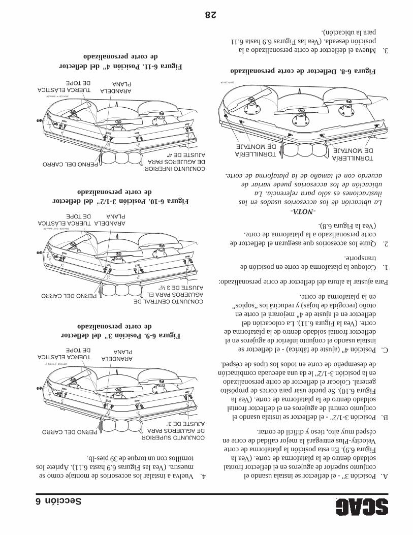
Sección 6
28
Figura 6-8. Deflector de corte personalizado
3.Mueva el deflector de corte personalizado a laposición deseada. (Vea las Figuras 6.9 hasta 6.11para la ubicación).
Figura 6-11. Posición 4" del deflectorde corte personalizado
Figura 6-10. Posición 3-1/2" del deflectorde corte personalizado
2004 CCB SP
TORNILLERÍA DE MONTAJETORNILLERÍA
DE MONTAJE
2004 CCB - 3" Setting SP
PERNO DEL CARROCONJUNTO SUPERIOR DE AGUJEROS PARA AJUSTE DE 3"
ARANDELAPLANA
TUERCA ELÁSTICA DE TOPE
2004 CCB - 3-1/2" Setting SP
PERNO DEL CARROCONJUNTO CENTRAL DEAGUJEROS PARA ELAJUSTE DE 3 ½"
ARANDELAPLANA
TUERCA ELÁSTICADE TOPE
2004 CCB - 4" Setting SP
PERNO DEL CARROCONJUNTO INFERIOR DE AGUJEROS PARA AJUSTE DE 4"
ARANDELAPLANA
TUERCA ELÁSTICADE TOPE
Figura 6-9. Posición 3" del deflectorde corte personalizado
A.Posición 3" - el deflector se instala usando elconjunto superior de agujeros en el deflector frontalsoldado dentro de la plataforma de corte. (Vea laFigura 6.9). En esta posición la plataforma de corteVelocity-Plus entregará la mejor calidad de corte encésped muy alto, tieso y difícil de cortar.
B.Posición 3-1/2" - el deflector se instala usando elconjunto central de agujeros en el deflector frontalsoldado dentro de la plataforma de corte. (Vea laFigura 6.10). Se puede usar para cortes de propósitogeneral. Colocar el deflector de corte personalizadoen la posición 3-1/2" le da una adecuada combinaciónde desempeño de corte en todos los tipos de césped.
C.Posición 4" (ajuste de fábrica) - el deflector seinstala usando el conjunto inferior de agujeros en eldeflector frontal soldado dentro de la plataforma decorte. (Vea la Figura 6.11). La colocación deldeflector en el ajuste de 4" mejorará el corte enotoño (recogida de hojas) y reducirá los “soplos”en la plataforma de corte.
Para ajustar la altura del deflector de corte personalizado:
1.Coloque la plataforma de corte en posición detransporte.
2.Quite los accesorios que aseguran el deflector decorte personalizado a la plataforma de corte.(Vea la Figura 6.8).
-NOTA-La ubicación de los accesorios usados en lasilustraciones es sólo para referencia. Laubicación de los accesorios puede variar deacuerdo con el tamaño de la plataforma de corte.
4.Vuelva a instalar los accesorios de montaje como semuestra. (Vea las Figuras 6.9 hasta 6.11). Apriete lostornillos con un torque de 39 pies-lb.
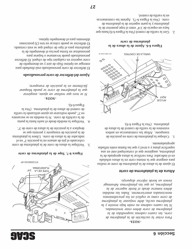
Sección 6
27
-NOTA-Para evitar la oscilación de la plataforma decorte, las cuatro cadenas suspendidas de laplataforma de corte deben estar tensionadas.Si las cuatro cadenas no están bajo tensión y laplataforma oscila, debe reajustar la plataformade corte como se explicó en los procedimientosmencionados anteriormente. Todas las medidasdeben tomarse desde el borde superior de laplataforma, ya que las plataformas Advantagetienen un borde inferior disparejo.
Altura de la plataforma de corte
El ajuste de la altura de la plataforma de corte se realizapara asegurar que la misma corte en la altura señaladaen el indicador. Para verificar la altura apropiada de laplataforma, asegúrese que el cortacésped esté en unasuperficie plana y a nivel y que las llantas estén infladasapropiadamente.
1.Coloque la plataforma de corte en posición detransporte. Afloje las contratuercas en ambosextremos de la varilla de control de la altura deplataforma. (Vea la Figura 6-6).
Figura 6-6. Ajuste de la altura de laplataforma de corte
2.Gire la varilla de control (Vea la Figura 6-6) hasta quehaya un espacio de 1/4" entre el tope posterior de laplataforma y la parte superior de la plataforma decorte. (Vea la Figura 6-7). Apriete las contratuercasen la varilla de control.
Figura 6-7. Tope de la plataforma de corte
3.Verifique la altura de corte de la plataforma de cortecolocando el pin de amarre en la posición 3" en elindicador de la altura de corte. Libere la plataformade la posición de transporte y permita que sedesplace a la posición de la altura de corte de 3".
4.Verifique la medida desde el suelo hasta la puntade la cuchilla de corte. Si la medida no se encuentraen 3", puede realizarse un ajuste utilizando la varillade control de altura de la plataforma. (Vea laFigura 6-6).
-NOTA-Si se tuvo que realizar un ajuste, asegúreseque la plataforma de corte se pueda bloquearfácilmente en la posición de transporte.
Ajuste del deflector de corte personalizado
El deflector de corte personalizado está diseñado paraentregar un óptimo flujo de aire y un desempeño decorte superior en cualquier tipo de césped. El deflectorpersonalizado puede levantarse o bajarse parapersonalizar en forma precisa el desempeño de laplataforma para el tipo de césped que se está cortando.El deflector se puede colocar en tres (3) posicionesdiferentes para el desempeño óptimo.
STC 2006 CDHA SP VARILLA DE CONTROL
AFLOJE AQUÍCUT
TINGHEIGHT
5
4 1/43 1/22 1/2X
1 1/4
STC2006CDS SP
TOPE DE LA PLATAFORMA
1/4"
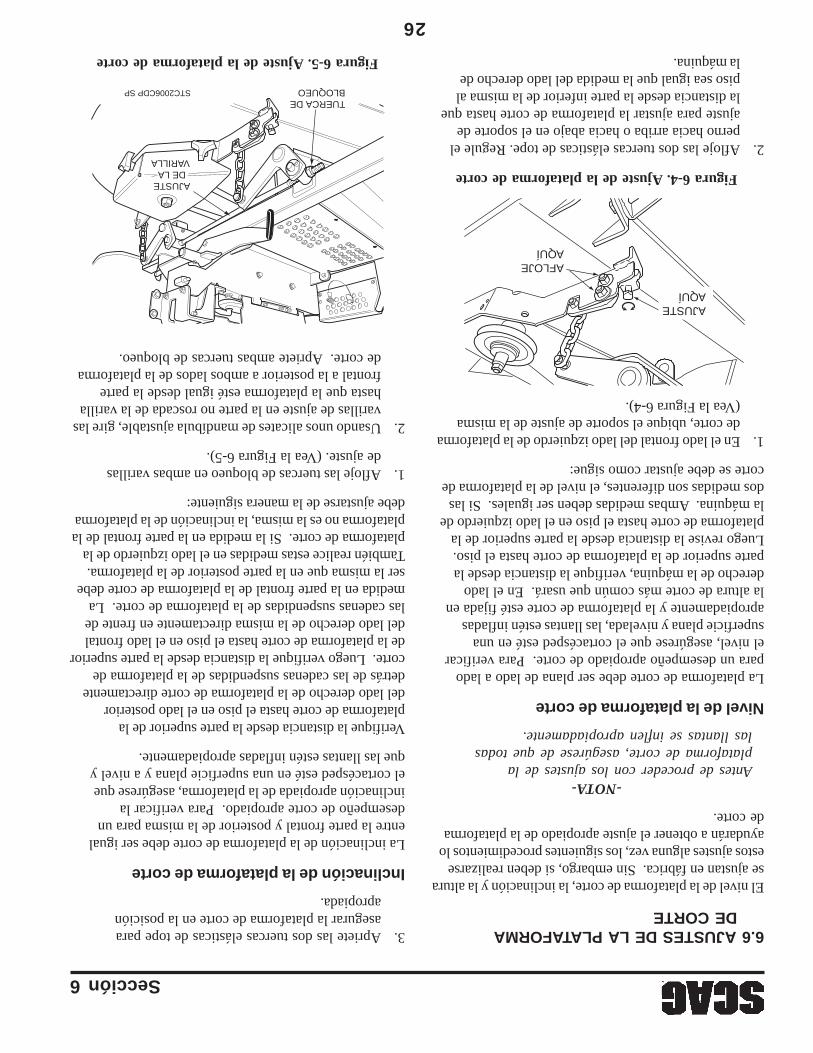
Sección 6
26
6.6 AJUSTES DE LA PLATAFORMADE CORTE
El nivel de la plataforma de corte, la inclinación y la alturase ajustan en fábrica. Sin embargo, si deben realizarseestos ajustes alguna vez, los siguientes procedimientos loayudarán a obtener el ajuste apropiado de la plataformade corte.
-NOTA-Antes de proceder con los ajustes de laplataforma de corte, asegúrese de que todaslas llantas se inflen apropiadamente.
Nivel de la plataforma de corte
La plataforma de corte debe ser plana de lado a ladopara un desempeño apropiado de corte. Para verificarel nivel, asegúrese que el cortacésped esté en unasuperficie plana y nivelada, las llantas estén infladasapropiadamente y la plataforma de corte esté fijada enla altura de corte más común que usará. En el ladoderecho de la máquina, verifique la distancia desde laparte superior de la plataforma de corte hasta el piso.Luego revise la distancia desde la parte superior de laplataforma de corte hasta el piso en el lado izquierdo dela máquina. Ambas medidas deben ser iguales. Si lasdos medidas son diferentes, el nivel de la plataforma decorte se debe ajustar como sigue:
1.En el lado frontal del lado izquierdo de la plataformade corte, ubique el soporte de ajuste de la misma(Vea la Figura 6-4).
Figura 6-4. Ajuste de la plataforma de corte
2.Afloje las dos tuercas elásticas de tope. Regule elperno hacia arriba o hacia abajo en el soporte deajuste para ajustar la plataforma de corte hasta quela distancia desde la parte inferior de la misma alpiso sea igual que la medida del lado derecho dela máquina.
3.Apriete las dos tuercas elásticas de tope paraasegurar la plataforma de corte en la posiciónapropiada.
Inclinación de la plataforma de corte
La inclinación de la plataforma de corte debe ser igualentre la parte frontal y posterior de la misma para undesempeño de corte apropiado. Para verificar lainclinación apropiada de la plataforma, asegúrese queel cortacésped esté en una superficie plana y a nivel yque las llantas estén infladas apropiadamente.
Verifique la distancia desde la parte superior de laplataforma de corte hasta el piso en el lado posteriordel lado derecho de la plataforma de corte directamentedetrás de las cadenas suspendidas de la plataforma decorte. Luego verifique la distancia desde la parte superiorde la plataforma de corte hasta el piso en el lado frontaldel lado derecho de la misma directamente en frente delas cadenas suspendidas de la plataforma de corte. Lamedida en la parte frontal de la plataforma de corte debeser la misma que en la parte posterior de la plataforma.También realice estas medidas en el lado izquierdo de laplataforma de corte. Si la medida en la parte frontal de laplataforma no es la misma, la inclinación de la plataformadebe ajustarse de la manera siguiente:
1.Afloje las tuercas de bloqueo en ambas varillasde ajuste. (Vea la Figura 6-5).
2.Usando unos alicates de mandíbula ajustable, gire lasvarillas de ajuste en la parte no roscada de la varillahasta que la plataforma esté igual desde la partefrontal a la posterior a ambos lados de la plataformade corte. Apriete ambas tuercas de bloqueo.
AFLOJE AQUÍ
AJUSTE AQUÍ
Figura 6-5. Ajuste de la plataforma de corte
TUERCA DE BLOQUEO
AJUSTE DE LA
VARILLA
STC2006CDP SP
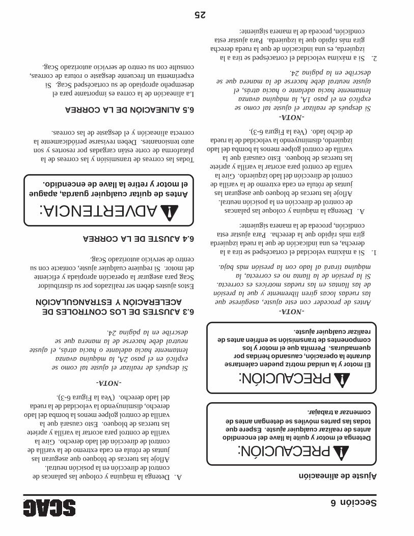
Sección 6
25
Ajuste de alineación
Detenga el motor y quite la llave del encendidoantes de realizar cualquier ajuste. Espere quetodas las partes móviles se detengan antes decomenzar a trabajar.
El motor y la unidad motriz pueden calentarsedurante la operación, causando heridas porquemaduras. Permita que el motor y loscomponentes de transmisión se enfríen antes derealizar cualquier ajuste.
-NOTA-Antes de proceder con este ajuste, asegúrese quelas ruedas locas giren libremente y que la presiónde las llantas en las ruedas motrices es correcta.Si la presión de la llanta no es correcta, lamáquina tirará al lado con la presión más baja.
1.Si a máxima velocidad el cortacésped se tira a laderecha, es una indicación de que la rueda izquierdagira más rápido que la derecha. Para ajustar estacondición, proceda de la manera siguiente:
A.Detenga la máquina y coloque las palancasde control de dirección en la posición neutral.Afloje las tuercas de bloqueo que aseguran lasjuntas de rótula en cada extremo de la varilla decontrol de dirección del lado izquierdo. Gire lavarilla de control para acortar la varilla y aprietelas tuercas de bloqueo.Esto causará que lavarilla de control golpee menos la bomba del ladoizquierdo, disminuyendo la velocidad de la ruedade dicho lado. (Vea la Figura 6-3).
-NOTA-Si después de realizar el ajuste tal como seexplicó en el paso 1A, la máquina avanzalentamente hacia adelante o hacia atrás, elajuste neutral debe hacerse de la manera que sedescribe en la página 24.
2.Si a máxima velocidad el cortacésped se tira a laizquierda, es una indicación de que la rueda derechagira más rápido que la izquierda. Para ajustar estacondición, proceda de la manera siguiente:
A.Detenga la máquina y coloque las palancas decontrol de dirección en la posición neutral.Afloje las tuercas de bloqueo que aseguran lasjuntas de rótula en cada extremo de la varilla decontrol de dirección del lado derecho. Gire lavarilla de control para acortar la varilla y aprietelas tuercas de bloqueo.Esto causará que lavarilla de control golpee menos la bomba del ladoderecho, disminuyendo la velocidad de la ruedadel lado derecho. (Vea la Figura 6-3).
-NOTA-
Si después de realizar el ajuste tal como seexplicó en el paso 2A, la máquina avanzalentamente hacia adelante o hacia atrás, el ajusteneutral debe hacerse de la manera que sedescribe en la página 24.
6.3 AJUSTES DE LOS CONTROLES DEACELERACIÓN Y ESTRANGULACIÓN
Estos ajustes deben ser realizados por su distribuidorScag para asegurar la operación apropiada y eficientedel motor. Si requiere cualquier ajuste, contacte con sucentro de servicio autorizado Scag.
6.4 AJUSTE DE LA CORREA
Todas las correas de transmisión y las correas de laplataforma de corte están cargadas por resortes y sonauto tensionantes. Deben revisarse periódicamente lacorrecta alineación y el desgaste de las correas.
6.5 ALINEACIÓN DE LA CORREA
La alineación de la correa es importante para eldesempeño apropiado de su cortacésped Scag. Siexperimenta un frecuente desgaste o rotura de correas,consulte con su centro de servicio autorizado Scag.
Antes de quitar cualquier guarda, apagueel motor y retire la llave de encendido.
PRECAUCIÓN:
PRECAUCIÓN:
ADVERTENCIA:
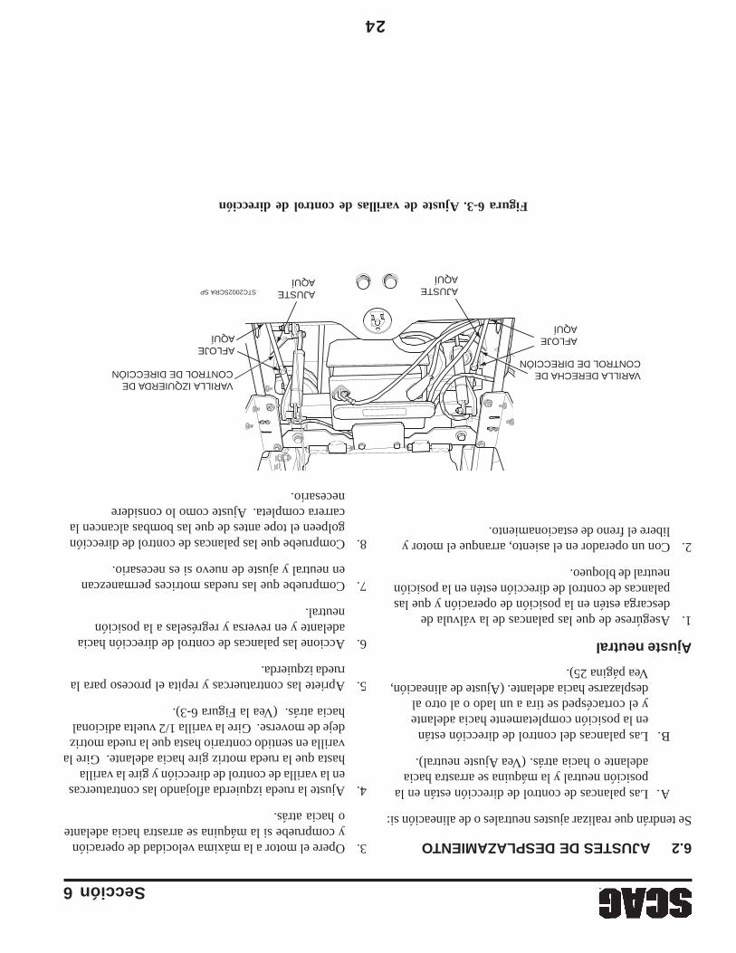
Sección 6
24
6.2 AJUSTES DE DESPLAZAMIENTO
Se tendrán que realizar ajustes neutrales o de alineación si:
A.Las palancas de control de dirección están en laposición neutral y la máquina se arrastra haciaadelante o hacia atrás. (Vea Ajuste neutral).
B.Las palancas del control de dirección estánen la posición completamente hacia adelantey el cortacésped se tira a un lado o al otro aldesplazarse hacia adelante. (Ajuste de alineación,Vea página 25).
Ajuste neutral
1.Asegúrese de que las palancas de la válvula dedescarga estén en la posición de operación y que laspalancas de control de dirección estén en la posiciónneutral de bloqueo.
2.Con un operador en el asiento, arranque el motor ylibere el freno de estacionamiento.
Figura 6-3. Ajuste de varillas de control de dirección
3.Opere el motor a la máxima velocidad de operacióny compruebe si la máquina se arrastra hacia adelanteo hacia atrás.
4.Ajuste la rueda izquierda aflojando las contratuercasen la varilla de control de dirección y gire la varillahasta que la rueda motriz gire hacia adelante. Gire lavarilla en sentido contrario hasta que la rueda motrizdeje de moverse. Gire la varilla 1/2 vuelta adicionalhacia atrás. (Vea la Figura 6-3).
5.Apriete las contratuercas y repita el proceso para larueda izquierda.
6.Accione las palancas de control de dirección haciaadelante y en reversa y regréselas a la posiciónneutral.
7.Compruebe que las ruedas motrices permanezcanen neutral y ajuste de nuevo si es necesario.
8.Compruebe que las palancas de control de direccióngolpeen el tope antes de que las bombas alcancen lacarrera completa. Ajuste como lo considerenecesario.
AJUSTE AQUÍ
AJUSTE AQUÍ
VARILLA IZQUIERDA DE CONTROL DE DIRECCIÓN VARILLA DERECHA DE
CONTROL DE DIRECCIÓNAFLOJE AQUÍ AFLOJE
AQUÍ
STC2002SCRA SP
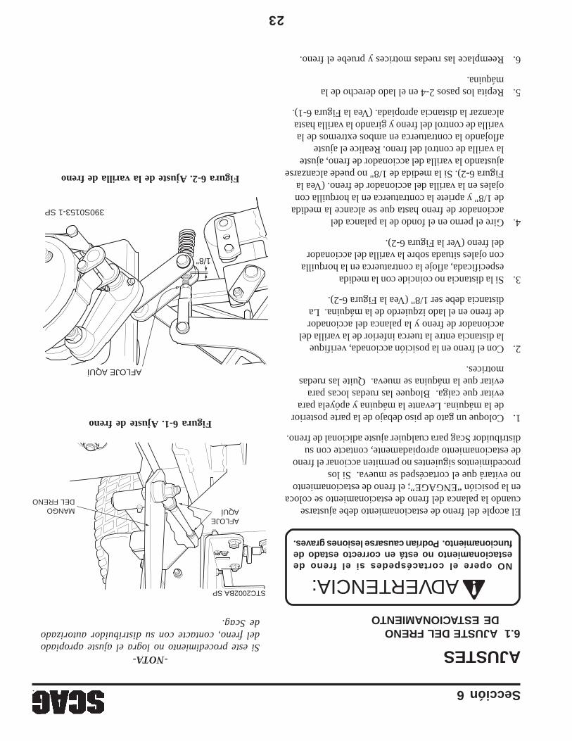
Sección 6
23
AJUSTES6.1 AJUSTE DEL FRENO
DE ESTACIONAMIENTO
NO opere el cortacéspedes si el freno deestacionamiento no está en correcto estado defuncionamiento. Podrían causarse lesiones graves.
El acople del freno de estacionamiento debe ajustarsecuando la palanca del freno de estacionamiento se colocaen la posición “ENGAGE”; el freno de estacionamientono evitará que el cortacésped se mueva. Si losprocedimientos siguientes no permiten accionar el frenode estacionamiento apropiadamente, contacte con sudistribuidor Scag para cualquier ajuste adicional de freno.
1.Coloque un gato de piso debajo de la parte posteriorde la máquina. Levante la máquina y apóyela paraevitar que caiga. Bloquee las ruedas locas paraevitar que la máquina se mueva. Quite las ruedasmotrices.
2.Con el freno en la posición accionada, verifiquela distancia entre la tuerca inferior de la varilla delaccionador de freno y la palanca del accionadorde freno en el lado izquierdo de la máquina. Ladistancia debe ser 1/8" (Vea la Figura 6-2).
3.Si la distancia no coincide con la medidaespecificada, afloje la contratuerca en la horquillacon ojales situada sobre la varilla del accionadordel freno (Ver la Figura 6-2).
4.Gire el perno en el fondo de la palanca delaccionador de freno hasta que se alcance la medidade 1/8" y apriete la contratuerca en la horquilla conojales en la varilla del accionador de freno. (Vea laFigura 6-2). Si la medida de 1/8" no puede alcanzarseajustando la varilla del accionador de freno, ajustela varilla de control del freno. Realice el ajusteaflojando la contratuerca en ambos extremos de lavarilla de control del freno y girando la varilla hastaalcanzar la distancia apropiada. (Vea la Figura 6-1).
5.Repita los pasos 2-4 en el lado derecho de lamáquina.
6.Reemplace las ruedas motrices y pruebe el freno.
Figura 6-2. Ajuste de la varilla de freno
Figura 6-1. Ajuste de freno
AFLOJE AQUÍ
1/8"
390S0153-1 SP
-NOTA-Si este procedimiento no logra el ajuste apropiadodel freno, contacte con su distribuidor autorizadode Scag.
AFLOJE AQUÍ
STC2002BA SP
MANGO DEL FRENO
ADVERTENCIA:
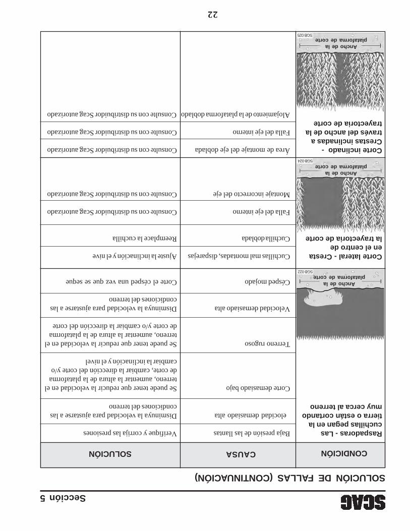
Sección 5
22
Raspadoras - LasBaja presión de las llantasVerifique y corrija las presionescuchillas pegan en latierra o están cortando�elocidad demasiado altaDisminuya la velocidad para ajustarse a lasmuy cerca al terrenocondiciones del terreno
Corte demasiado bajoSe puede tener que reducir la velocidad en elterreno, aumentar la altura de la plataformade corte, cambiar la dirección del corte y/ocambiar la inclinación y el nivel
Terreno rugosoSe puede tener que reducir la velocidad en elterreno, aumentar la altura de la plataformade corte y/o cambiar la dirección del corte
Velocidad demasiado altaDisminuya la velocidad para ajustarse a lascondiciones del terreno
Césped mojadoCorte el césped una vez que se seque
Corte lateral - CrestaCuchillas mal montadas, disparejasAjuste la inclinación y el nive�en el centro dela trayectoria de corteCuchilla dobladaReemplace la cuchilla
Falla del eje internoConsulte con su distribuidor Scag autorizado
Montaje incorrecto del ejeConsulte con su distribuidor Scag autorizado
Corte inclinado -Área de montaje del eje dobladaConsulte con su distribuidor Scag autorizadoCrestas inclinadas através del ancho de laFalla del eje internoConsulte con su distribuidor Scag autorizadotrayectoria de corte
Alojamiento de la plataforma dobladoConsulte con su distribuidor Scag autorizado
CONDICIÓNCAUSASOLUCIÓN
SOLUCIÓN DE FALLAS (CONTINUACIÓN)
Ancho de laplataforma de corte
SGB 022
Ancho de laplataforma de corte
SGB 024
Ancho de laplataforma de corte
SGB 025
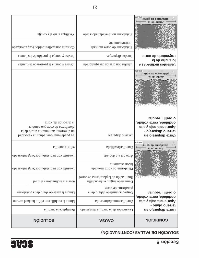
Sección 5
21
Corte disparejo enLevantador de la cuchilla desgastadoReemplace la cuchillaterreno plano -Apariencia baja y altaCuchilla montada invertidaMonte la cuchilla con el filo hacia elterrenoondulada,corte volado,o perfil irregularCésped acumulado debajo de laLimpie la parte de abajo de la plataforma
plataforma de corte
Demasiado ángulo en la cuchillaAjuste la inclinación y el nivel(inclinación de la plataforma de corte)
Plataforma de corte montadaConsulte con su distribuidor Scag autorizadoincorrectamente
Área del eje dobladaConsulte con su distribuidor Scag autorizado
Cuchilla desafiladaAfile la cuchilla
SOLUCIÓN DE FALLAS (CONTINUACIÓN)
Salientes inclinadas aLlantas con presión desequilibradaRevise y corrija la presión de las llantaslo ancho de latrayectoria de corteRuedas disparejasRevise y corrija la presión de las llantas
Plataforma de corte montadaConsulte con su distribuidor Scag autorizadoincorrectamente
Plataforma no nivelada lado a ladoVerifique el nivel y corrija
CONDICIÓNCAUSASOLUCIÓN
Corte disparejo enTerreno disparejoSe puede tener que reducir la velocidadterreno disparejo -en el terreno, aumentar la altura de laApariencia baja y altaplataforma de corte y/o cambiarondulada,corte volado,la dirección del corteo perfil irregular
Ancho de laplataforma de corte
SGB 020
Ancho de laplataforma de corte
SGB 021
Ancho de laplataforma de corte
SGB 023
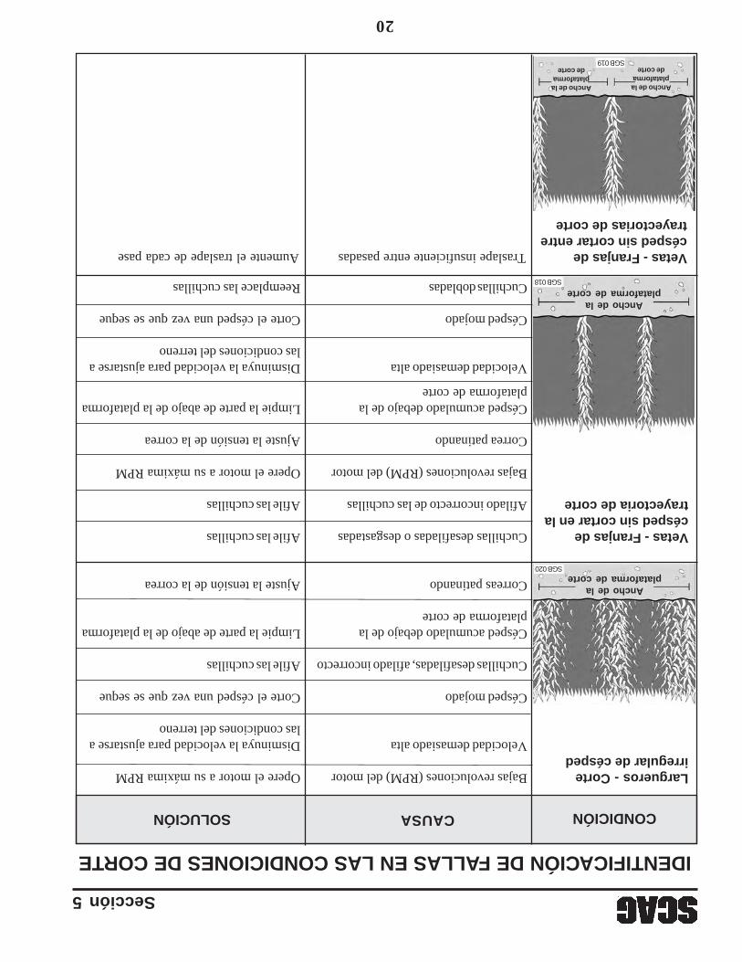
Sección 5
20
Largueros - CorteBajas revoluciones (RPM) del motorOpere el motor a su máxima RPMirregular de césped
Velocidad demasiado altaDisminuya la velocidad para ajustarse alas condiciones del terreno
Césped mojadoCorte el césped una vez que se seque
Cuchillas desafiladas, afilado incorrectoAfile las cuchillas
Césped acumulado debajo de laLimpie la parte de abajo de la plataformaplataforma de corte
Correas patinandoAjuste la tensión de la correa
Vetas - Franjas deCuchillas desafiladas o desgastadasAfile las cuchillascésped sin cortar en latrayectoria de corteAfilado incorrecto de las cuchillasAfile las cuchillas
Bajas revoluciones (RPM) del motorOpere el motor a su máxima RPM
Correa patinandoAjuste la tensión de la correa
Césped acumulado debajo de laLimpie la parte de abajo de la plataformaplataforma de corte
Velocidad demasiado altaDisminuya la velocidad para ajustarse alas condiciones del terreno
Césped mojadoCorte el césped una vez que se seque
Cuchillas dobladasReemplace las cuchillas
CONDICIÓNCAUSASOLUCIÓN
Vetas - Franjas deTraslape insuficiente entre pasadasAumente el traslape de cada pasecésped sin cortar entretrayectorias de corte
IDENTIFICACIÓN DE FALLAS EN LAS CONDICIONES DE CORTE
Ancho de laplataforma de corte
SGB 020
Ancho de laplataforma de corte
SGB 018
Ancho de laplataforma
de corte
Ancho de laplataforma
de corteSGB 019
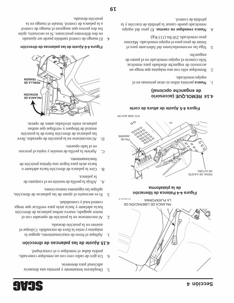
19
Sección 4
Figura 4-5 Ajuste de altura de corte
Figura 4-4 Palanca de liberaciónde la plataforma
4.14 REMOLQUE (accesoriode enganche opcional)
1.Nunca permita niños ni otras personas en elequipo remolcado.
2.Remolque sólo con una máquina que tenga unaccesorio de enganche diseñado para remolcar.Sólo conecte el equipo remolcado en el punto deenganche.
3.Siga las recomendaciones del fabricante para ellímite de peso para el equipo remolcado. Máximopeso remolcado 250 lbs (113 Kg).
4.Nunca remolque en cuestas. El peso del equiporemolcado puede causar la pérdida de tracción y lapérdida de control.
PEDAL DE AJUSTE DE ALTURA
PIN DE AMARRE
STC 2006 ACH SP
CUT TING
HEIGHT5
4 1/43 1/22 1/2X
1 1/4
STC 2006 DRL SP
PALANCA DE LIBERACIÓN DE LA PLATAFORMA
5.Desplácese lentamente y permita una distanciaadicional para detenerse.
6.Un giro de radio cero con un remolque conectado,podría dañar el remolque o el cortacésped.
4.15 Ajuste de las palancas de dirección
1.Aplique el freno de estacionamiento, apague lamáquina y retire la llave de encendido. Coloque elasiento en la posición deseada.
2.Al encontrarse en la posición de operador con elmotor apagado, mueva ambas palancas de direcciónhacia adelante y hacia atrás para verificar que tengacontrol total y comodidad.
3.Si es necesario el ajuste de las palancas de dirección,aplique las siguientes instrucciones.
A.Afloje la perilla de tensión en el conjunto dela palanca.
B.Gire la palanca de dirección hacia adelante ohacia atrás para lograr una óptima posición defuncionamiento.
C.Apriete la perilla de tensión y repita el procesoen el lado opuesto.
D.Al encontrarse en la posición de operador, llevelas palancas de dirección fuera de la posiciónneutral de bloqueo y verifique que ambaspalancas estén niveladas antes de operar.
4.El mango de control también puede ser ajustadoen dos diferentes posiciones. Si es necesario, quitelos dos pernos que aseguran el mango de controla la palanca de control. Instale el mango en laposición deseada.
Figura 4-6 Ajuste de las palancas de dirección
PERILLA DE TENSIÓN
PALANCA DEROTACIÓN
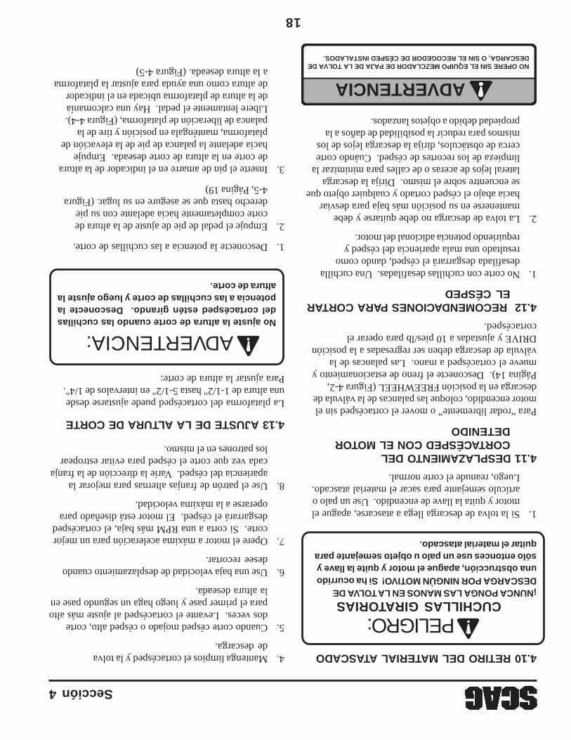
18
Sección 4
4.10 RETIRO DEL MATERIAL ATASCADO
CUCHILLAS GIRATORIAS¡NUNCA PONGA LAS MANOS EN LA TOLVA DEDESCARGA POR NINGÚN MOTIVO! Si ha ocurridouna obstrucción, apague el motor y quite la llave ysólo entonces use un palo u objeto semejante paraquitar el material atascado.
1.Si la tolva de descarga llega a atascarse, apague elmotor y quita la llave de encendido. Use un palo oartículo semejante para sacar el material atascado.Luego, reanude el corte normal.
4.11 DESPLAZAMIENTO DELCORTACÉSPED CON EL MOTORDETENIDO
Para “rodar libremente” o mover el cortacésped sin elmotor encendido, coloque las palancas de la válvula dedescarga en la posición FREEWHEEL (Figura 4-2,Página 14). Desconecte el freno de estacionamiento ymueve el cortacésped a mano. Las palancas de laválvula de descarga deben ser regresadas a la posiciónDRIVE y ajustadas a 10 pies/lb para operar elcortacésped.
4.12 RECOMENDACIONES PARA CORTAREL CÉSPED
1.No corte con cuchillas desafiladas. Una cuchilladesafilada desgarrará el césped, dando comoresultado una mala apariencia del césped yrequiriendo potencia adicional del motor.
2.La tolva de descarga no debe quitarse y debemantenerse en su posición más baja para desviarhacia abajo el césped cortado y cualquier objeto quese encuentre sobre el mismo. Dirija la descargalateral lejos de aceras o de calles para minimizar lalimpieza de los recortes de césped. Cuándo cortecerca de obstáculos, dirija la descarga lejos de losmismos para reducir la posibilidad de daños a lapropiedad debido a objetos lanzados.
NO OPERE SIN EL EQUIPO MEZCLADOR DE PAJA DE LA TOLVA DEDESCARGA, O SIN EL RECOGEDOR DE CÉSPED INSTALADOS.
ADVERTENCIA
4.13 AJUSTE DE LA ALTURA DE CORTE
La plataforma del cortacésped puede ajustarse desdeuna altura de 1-1/2" hasta 5-1/2" en intervalos de 1/4".Para ajustar la altura de corte:
No ajuste la altura de corte cuando las cuchillasdel cortacésped estén girando. Desconecte lapotencia a las cuchillas de corte y luego ajuste laaltura de corte.
1.Desconecte la potencia a las cuchillas de corte.
2.Empuje el pedal de pie de ajuste de la altura decorte completamente hacia adelante con su piederecho hasta que se asegure en su lugar. (Figura4-5, Página 19)
3.Inserte el pin de amarre en el indicador de la alturade corte en la altura de corte deseada. Empujehacia adelante la palanca de pie de la elevación deplataforma, manténgala en posición y tire de lapalanca de liberación de plataforma, (Figura 4-4).Libere lentamente el pedal. Hay una calcomaníade la altura de plataforma ubicada en el indicadorde altura como una ayuda para ajustar la plataformaa la altura deseada. (Figura 4-5)
4.Mantenga limpios el cortacésped y la tolvade descarga.
5.Cuando corte césped mojado o césped alto, cortedos veces. Levante el cortacésped al ajuste más altopara el primer pase y luego haga un segundo pase enla altura deseada.
6.Use una baja velocidad de desplazamiento cuandodesee recortar.
7.Opere el motor a máxima aceleración para un mejorcorte. Si corta a una RPM más baja, el cortacéspeddesgarrará el césped. El motor está diseñado paraoperarse a la máxima velocidad.
8.Use el patrón de franjas alternas para mejorar laapariencia del césped. Varíe la dirección de la franjacada vez que corte el césped para evitar estropearlos patrones en el mismo.
PELIGRO:
ADVERTENCIA:
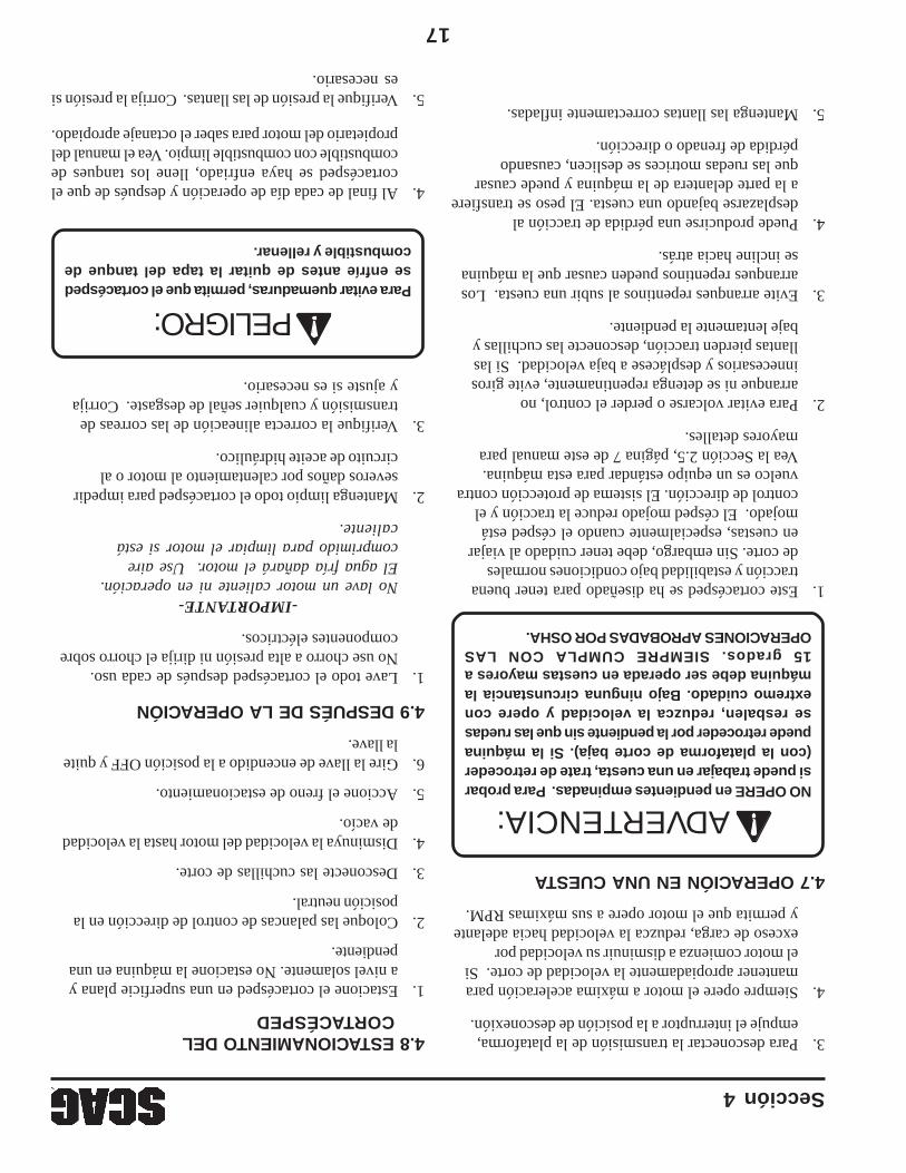
17
Sección 4
4.8 ESTACIONAMIENTO DELCORTACÉSPED
1.Estacione el cortacésped en una superficie plana ya nivel solamente. No estacione la máquina en unapendiente.
2.Coloque las palancas de control de dirección en laposición neutral.
3.Desconecte las cuchillas de corte.
4.Disminuya la velocidad del motor hasta la velocidadde vacío.
5.Accione el freno de estacionamiento.
6.Gire la llave de encendido a la posición OFF y quitela llave.
4.9 DESPUÉS DE LA OPERACIÓN
1.Lave todo el cortacésped después de cada uso.No use chorro a alta presión ni dirija el chorro sobrecomponentes eléctricos.
-IMPORTANTE-No lave un motor caliente ni en operación.El agua fría dañará el motor. Use airecomprimido para limpiar el motor si estácaliente.
2.Mantenga limpio todo el cortacésped para impedirseveros daños por calentamiento al motor o alcircuito de aceite hidráulico.
3.Verifique la correcta alineación de las correas detransmisión y cualquier señal de desgaste. Corrijay ajuste si es necesario.
Para evitar quemaduras, permita que el cortacéspedse enfríe antes de quitar la tapa del tanque decombustible y rellenar.
4.Al final de cada día de operación y después de que elcortacésped se haya enfriado, llene los tanques decombustible con combustible limpio. Vea el manual delpropietario del motor para saber el octanaje apropiado.
3.Para desconectar la transmisión de la plataforma,empuje el interruptor a la posición de desconexión.
4.Siempre opere el motor a máxima aceleración paramantener apropiadamente la velocidad de corte. Siel motor comienza a disminuir su velocidad porexceso de carga, reduzca la velocidad hacia adelantey permita que el motor opere a sus máximas RPM.
4.7 OPERACIÓN EN UNA CUESTA
NO OPERE en pendientes empinadas. Para probarsi puede trabajar en una cuesta, trate de retroceder(con la plataforma de corte baja). Si la máquinapuede retroceder por la pendiente sin que las ruedasse resbalen, reduzca la velocidad y opere conextremo cuidado. Bajo ninguna circunstancia lamáquina debe ser operada en cuestas mayores a15 grados. SIEMPRE CUMPLA CON LASOPERACIONES APROBADAS POR OSHA.
1.Este cortacésped se ha diseñado para tener buenatracción y estabilidad bajo condiciones normalesde corte. Sin embargo, debe tener cuidado al viajaren cuestas, especialmente cuando el césped estámojado. El césped mojado reduce la tracción y elcontrol de dirección. El sistema de protección contravuelco es un equipo estándar para esta máquina.Vea la Sección 2.5, página 7 de este manual paramayores detalles.
2.Para evitar volcarse o perder el control, noarranque ni se detenga repentinamente, evite girosinnecesarios y desplácese a baja velocidad. Si lasllantas pierden tracción, desconecte las cuchillas ybaje lentamente la pendiente.
3.Evite arranques repentinos al subir una cuesta. Losarranques repentinos pueden causar que la máquinase incline hacia atrás.
4.Puede producirse una pérdida de tracción aldesplazarse bajando una cuesta. El peso se transfierea la parte delantera de la máquina y puede causarque las ruedas motrices se deslicen, causandopérdida de frenado o dirección.
5.Mantenga las llantas correctamente infladas.5.Verifique la presión de las llantas. Corrija la presión si
es necesario.
ADVERTENCIA:
PELIGRO:
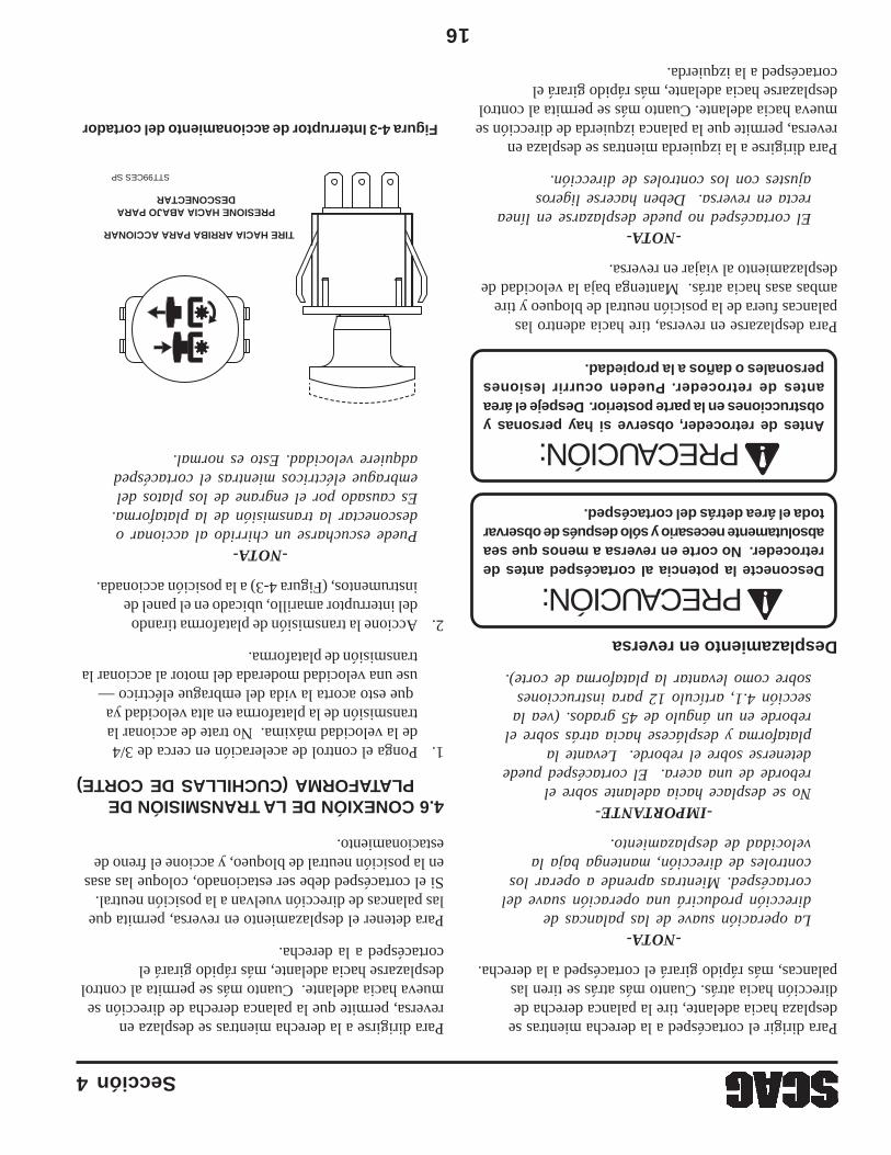
16
Sección 4
Para dirigir el cortacésped a la derecha mientras sedesplaza hacia adelante, tire la palanca derecha dedirección hacia atrás. Cuanto más atrás se tiren laspalancas, más rápido girará el cortacésped a la derecha.
-NOTA-La operación suave de las palancas dedirección producirá una operación suave delcortacésped. Mientras aprende a operar loscontroles de dirección, mantenga baja lavelocidad de desplazamiento.
-IMPORTANTE-No se desplace hacia adelante sobre elreborde de una acera. El cortacésped puededetenerse sobre el reborde. Levante laplataforma y desplácese hacia atrás sobre elreborde en un ángulo de 45 grados. (vea lasección 4.1, artículo 12 para instruccionessobre como levantar la plataforma de corte).
Desplazamiento en reversa
Desconecte la potencia al cortacésped antes deretroceder. No corte en reversa a menos que seaabsolutamente necesario y sólo después de observartoda el área detrás del cortacésped.
Antes de retroceder, observe si hay personas yobstrucciones en la parte posterior. Despeje el áreaantes de retroceder. Pueden ocurrir lesionespersonales o daños a la propiedad.
Para desplazarse en reversa, tire hacia adentro laspalancas fuera de la posición neutral de bloqueo y tireambas asas hacia atrás. Mantenga baja la velocidad dedesplazamiento al viajar en reversa.
-NOTA-El cortacésped no puede desplazarse en línearecta en reversa. Deben hacerse ligerosajustes con los controles de dirección.
Para dirigirse a la izquierda mientras se desplaza enreversa, permite que la palanca izquierda de dirección semueva hacia adelante. Cuanto más se permita al controldesplazarse hacia adelante, más rápido girará elcortacésped a la izquierda.
Para dirigirse a la derecha mientras se desplaza enreversa, permite que la palanca derecha de dirección semueva hacia adelante. Cuanto más se permita al controldesplazarse hacia adelante, más rápido girará elcortacésped a la derecha.
Para detener el desplazamiento en reversa, permita quelas palancas de dirección vuelvan a la posición neutral.Si el cortacésped debe ser estacionado, coloque las asasen la posición neutral de bloqueo, y accione el freno deestacionamiento.
4.6 CONEXIÓN DE LA TRANSMISIÓN DEPLATAFORMA (CUCHILLAS DE CORTE)
1.Ponga el control de aceleración en cerca de 3/4de la velocidad máxima. No trate de accionar latransmisión de la plataforma en alta velocidad ya que esto acorta la vida del embrague eléctrico —use una velocidad moderada del motor al accionar latransmisión de plataforma.
2.Accione la transmisión de plataforma tirandodel interruptor amarillo, ubicado en el panel deinstrumentos, (Figura 4-3) a la posición accionada.
-NOTA-Puede escucharse un chirrido al accionar odesconectar la transmisión de la plataforma.Es causado por el engrane de los platos delembrague eléctricos mientras el cortacéspedadquiere velocidad. Esto es normal.
Figura 4-3 Interruptor de accionamiento del cortador
STT99CES SP
TIRE HACIA ARRIBA PARA ACCIONAR
PRESIONE HACIA ABAJO PARADESCONECTAR
PRECAUCIÓN:
PRECAUCIÓN:
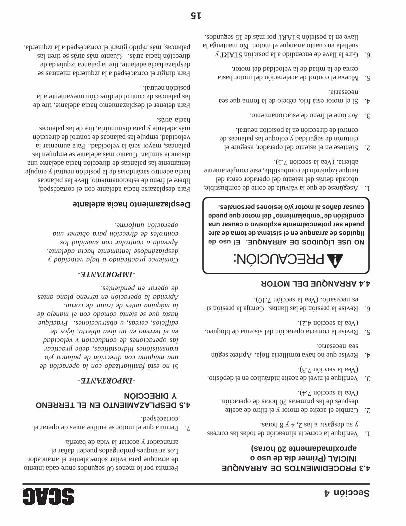
15
Sección 4
4.3 PROCEDIMIENTOS DE ARRANQUEINICIAL (Primer día de uso oaproximadamente 20 horas)
1.Verifique la correcta alineación de todas las correasy su desgaste a las 2, 4 y 8 horas.
2.Cambie el aceite de motor y el filtro de aceitedespués de las primeras 20 horas de operación.(Vea la sección 7.4).
3.Verifique el nivel de aceite hidráulico en el depósito.(Vea la sección 7.3).
4.Revise que no haya tornillería floja. Apriete segúnsea necesario.
5.Revise la correcta operación del sistema de bloqueo.(Vea la sección 4.2).
6.Revise la presión de las llantas. Corrija la presión sies necesario. (Vea la sección 7.10).
4.4 ARRANQUE DEL MOTOR
NO USE LÍQUIDOS DE ARRANQUE. El uso delíquidos de arranque en el sistema de toma de airepuede ser potencialmente explosivo o causar unacondición de “embalamiento” del motor que puedecausar daños al motor y/o lesiones personales.
1.Asegúrese de que la válvula de corte de combustible,ubicada detrás del asiento del operador cerca deltanque izquierdo de combustible, esté completamenteabierta. (Vea la sección 7.5).
2.Siéntese en el asiento del operador, asegure elcinturón de seguridad y coloque las palancas decontrol de dirección en la posición neutral.
3.Accione el freno de estacionamiento.
4.Si el motor está frío, cébelo de la forma que seanecesaria.
5.Mueva el control de aceleración del motor hastacerca de la mitad de la velocidad del motor.
6.Gire la llave de encendido a la posición START ysuéltela en cuanto arranque el motor. No mantenga lallave en la posición START por más de 15 segundos.
Permita por lo menos 60 segundos entre cada intentode arranque para evitar sobrecalentar el arrancador.Los arranques prolongados pueden dañar elarrancador y acortar la vida de batería.
7.Permita que el motor se entibie antes de operar elcortacésped.
4.5 DESPLAZAMIENTO EN EL TERRENOY DIRECCIÓN
-IMPORTANTE-
Si no está familiarizado con la operación deuna máquina con dirección de palanca y/otransmisiones hidrostáticas, debe practicarlas operaciones de conducción y velocidaden el terreno en un área abierta, lejos deedificios, cercas, u obstrucciones. Practiquehasta que se sienta cómodo con el manejo dela máquina antes de tratar de cortar.Aprenda la operación en terreno plano antesde operar en pendientes.
-IMPORTANTE-
Comience practicando a baja velocidad ydesplazándose lentamente hacia adelante.Aprenda a controlar con suavidad loscontroles de dirección para obtener unaoperación uniforme.
Desplazamiento hacia adelante
Para desplazarse hacia adelante con el cortacésped,libere el freno de estacionamiento, lleve las palancashacia adentro sacándolas de la posición neutral y empujelentamente las palancas de dirección hacia adelante unadistancia similar. Cuanto más adelante se empujen laspalancas, mayor será la velocidad. Para aumentar lavelocidad, empuje las palancas de control de direcciónmás adelante y para disminuirla, tire de las palancashacia atrás.
Para detener el desplazamiento hacia adelante, tire delas palancas de control de dirección nuevamente a laposición neutral.
Para dirigir el cortacésped a la izquierda mientras sedesplaza hacia adelante, tire la palanca izquierda dedirección hacia atrás. Cuanto más atrás se tiren laspalancas, más rápido girará el cortacésped a la izquierda.
PRECAUCIÓN:
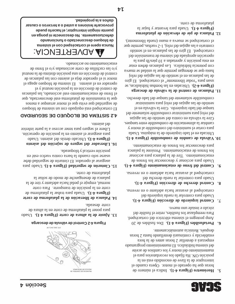
14
Sección 4
PALANCAS DE CONTROL DE VÁLVULA DE DESCARGA
STC 2001 DVC1 SP
5.Horómetro (Figura 4-1). Indica el número dehoras que ha operado el motor. Opera cuando elinterruptor de la llave de encendido está en laposición ON. Ha fijado los recordatorios para elmantenimiento del motor y los cambios de aceitedel sistema hidráulico. El mantenimiento programadoempezará a destellar 2 horas antes de la horaestablecida y continuará destellando hasta 2 horasdespués. Reinicia automáticamente.
6.Portafusibles (Figura 4-1). Dos fusibles de 20Amp protegen el sistema eléctrico del cortacésped.Para reemplazar los fusibles, retire el fusible delzócalo e instale uno nuevo.
7.Control izquierdo de dirección (Figura 4-1).Usado para controlar la rueda izquierda delcortacésped al avanzar hacia adelante o en reversa.
8.Control derecho de dirección (Figura 4-1).Usado para controlar la rueda derecha delcortacésped al avanzar hacia adelante o en reversa.
9.Control del freno de estacionamiento (Figura 4-1).Usado para accionar y desconectar los frenos deestacionamiento. Tire de la palanca para accionarlos frenos de estacionamiento. Presione la palancapara desconectar los frenos de estacionamiento.
10.Válvula de cambio de combustible (Figura 4-1).Ubicada en el lado izquierdo de la máquina. Usadapara cortar el suministro del combustible al motor ycambiar la alimentación de combustible entre tanques.Gire la válvula en contra del sentido de las agujasdel reloj para suministrar combustible solamente deltanque del lado izquierdo. Gire la válvula en elsentido de las agujas del reloj para suministrarcombustible solamente del tanque del lado derecho.
11.Palancas de control de la válvula de descarga(Figura 4-2). Ubicadas en las bombas hidráulicas, seusan para “rodar libremente” el cortacésped. El girode las palancas en el sentido de las agujas del relojhasta que se detengan permite que la unidad se muevacon potencia hidráulica. Las palancas deben estaren esta posición y apretadas a 10 pies/lb para laoperación apropiada del sistema de transmisión delcortacésped. El giro de las palancas en el sentidocontrario a las agujas del reloj, 1-2 vueltas, permite queel cortacésped se mueva a mano (rueda libremente).
12. Palanca de pie de elevación de plataforma(Figura 4-1). Usada para levantar y bajar laplataforma de corte.
Figura 4-2 Control de válvula de descarga
13.Ajuste de la altura de corte (Figura 4-1). Usadopara poner la plataforma de corte en la altura decorte deseada.
14. Palanca de liberación de la plataforma de corte(Figura 4-1). Usada para trabar la plataforma decorte en la posición de transporte. Para cortenormal, empuje el pedal hacia adelante y tire de lapalanca de desenganche de modo de soltar laplataforma de corte.
15.Cinturón de seguridad (Figura 4-1). Usado paraasegurar al operador. El cinturón de seguridad debeusarse solo cuando la barra contra vuelco esté enposición vertical y bloqueada.
16.Liberador del seguro de sujeción del asiento(Figura 4-1). Ubicado detrás del asiento. Usadopara asegurar el asiento en la posición de operación.Libere el seguro para tener acceso a la parte inferiordel asiento.
4.2 SISTEMA DE BLOQUEO DE SEGURIDADEl cortacésped está equipado con un sistema de bloqueode seguridad que evita que el motor arranque a menosque la transmisión de plataforma esté desconectada, queel freno de estacionamiento esté accionado, las palancasde control de dirección en la posición neutral y eloperador en el asiento. El sistema de bloqueo apaga elmotor si el operador deja el asiento con las palancas decontrol de dirección en una posición distinta de la neutraly/o las cuchillas de corte accionadas y/o el freno deestacionamiento no accionado.
Nunca opere el cortacésped con el sistemade bloqueo desconectado o funcionandodefectuosamente. No desconecte ni ponga enpuente ningún interruptor; el hacerlo puedeprovocarle lesiones a usted o a terceros o causardaños a la propiedad.
ADVERTENCIA:
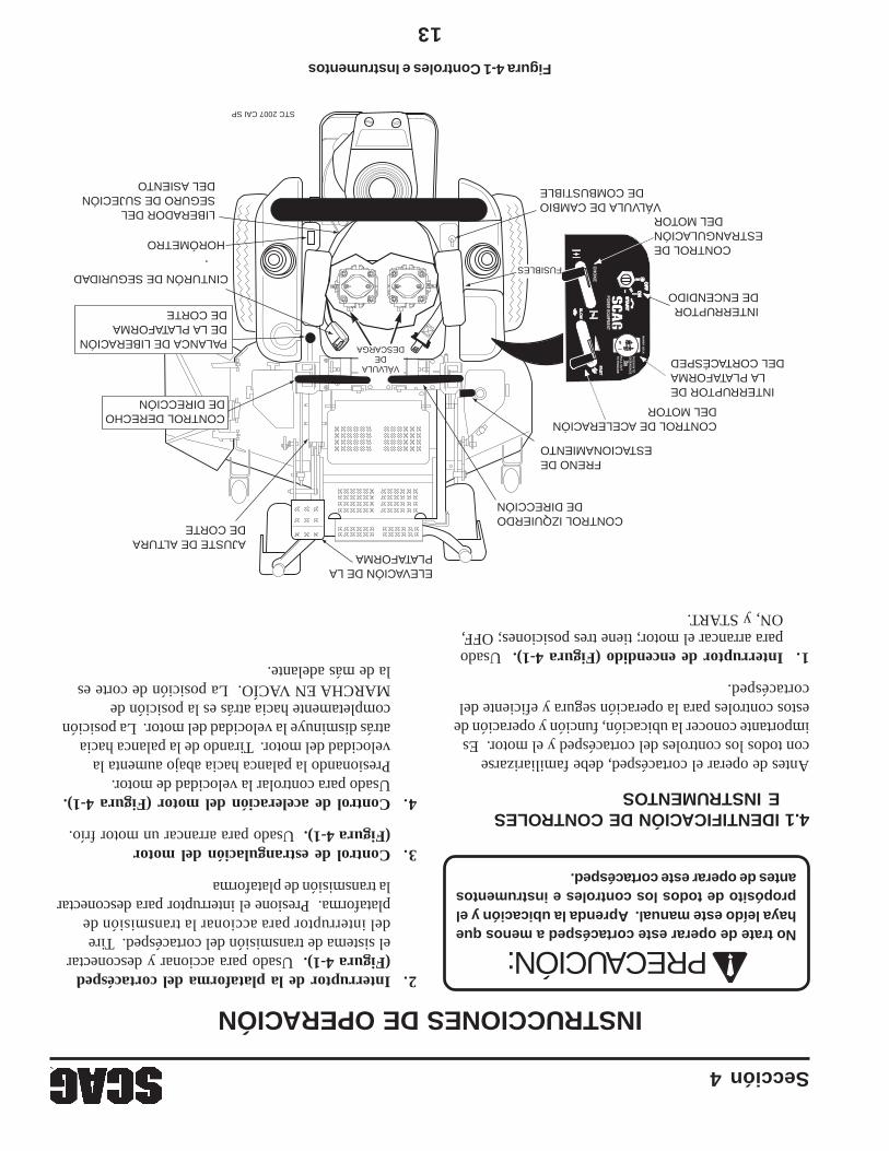
13
Sección 4
INSTRUCCIONES DE OPERACIÓN
No trate de operar este cortacésped a menos quehaya leído este manual. Aprenda la ubicación y elpropósito de todos los controles e instrumentosantes de operar este cortacésped.
4.1 IDENTIFICACIÓN DE CONTROLESE INSTRUMENTOS
Antes de operar el cortacésped, debe familiarizarsecon todos los controles del cortacésped y el motor. Esimportante conocer la ubicación, función y operación deestos controles para la operación segura y eficiente delcortacésped.
1.Interruptor de encendido (Figura 4-1). Usadopara arrancar el motor; tiene tres posiciones; OFF,ON, y START.
2.Interruptor de la plataforma del cortacésped(Figura 4-1). Usado para accionar y desconectarel sistema de transmisión del cortacésped. Tiredel interruptor para accionar la transmisión deplataforma. Presione el interruptor para desconectarla transmisión de plataforma
3.Control de estrangulación del motor(Figura 4-1). Usado para arrancar un motor frío.
4.Control de aceleración del motor (Figura 4-1).Usado para controlar la velocidad de motor.Presionando la palanca hacia abajo aumenta lavelocidad del motor. Tirando de la palanca haciaatrás disminuye la velocidad del motor. La posicióncompletamente hacia atrás es la posición deMARCHA EN VACÍO. La posición de corte esla de más adelante.
Figura 4-1 Controles e Instrumentos
ELEVACIÓN DE LA PLATAFORMA
VÁLVULA DE CAMBIODE COMBUSTIBLE
CONTROL IZQUIERDODE DIRECCIÓN
FRENO DEESTACIONAMIENTO
AJUSTE DE ALTURA DE CORTE
INTERRUPTOR DE ENCENDIDO
INTERRUPTOR DE LA PLATAFORMA
DEL CORTACÉSPED
CONTROL DE ACELERACIÓN DEL MOTOR
CONTROL DE ESTRANGULACIÓN
DEL MOTOR
STC 2007 CAI SP
POWER EQUIPM
ENT
CH
OK
E
OF
FO
FF
ON
ONS
TAR
TS
TAR
T
FAS
TFA
ST
SL
OW
SL
OW
MO
WE
R D
EC
K
PU
SH
IN TO
DIS
EN
GA
GE
PU
LL
OU
T
TO E
NG
AG
E
HORÓMETRO
FUSIBLES
PALANCA DE LIBERACIÓN DE LA PLATAFORMA DE CORTE
VÁLVULADE
DESCARGA
CINTURÓN DE SEGURIDAD
CONTROL DERECHO DE DIRECCIÓN
LIBERADOR DEL SEGURO DE SUJECIÓN DEL ASIENTO
PRECAUCIÓN:

12
Sección 3
3.3 TRACTOR (CONTINUACIÓN)
Velocidad de desplazamiento: Adelante................................................................................0-10 MPH (0-16 Kph) Reversa..................................................................................0-5 MPH (0-8 Kph)
3.4 PLATAFORMA DE CORTE
Tipo:...........................................................................................Flotante, ajustable, anti raspado, de diseño híbrido que combinadiseños delantero y de montaje frontal
Construcción:.............................................................................Construcción de plataforma de triple placa, la parte superior de laplataforma consta de tres placas de acero que totalizan casi 1/2" deacero, faldón de plataforma calibre 7 (3/16")
Ancho de corte:.........................................................................48" (122.0 cm), 52" (132.0 cm)Ajuste de altura de corte:...........................................................Ajuste con palanca de pie desde el asiento del operador, desde
1.00" a 5.5" en incrementos de 1/4"Cuchillas de corte:......................................................................Grosor 197, borde cepillado, material Marbain™ resistente al desgasteAccionamiento de las cuchillas:................................................Embrague eléctrico de accionamiento de cuchilla con interruptor
de panel de control conectado a la plataforma de corte a través deuna correa
Abertura de descarga:................................................................Abertura de descarga extra ancha con tolva de descarga cargadapor resorte y deflector turbo
Ejes:............................................................................................Servicio pesado, 1-1/8" en la parte superior, cuerpo fundido,rodamiento de rodillos cónicos, bajo mantenimiento con conexiónde grasa en la parte superior y cabezal móvil de alivio de excesode grasa
Poleas del eje:.............................................................................Acero partido con cubos cónicos de fácil desmontajeCorreas de la plataforma de corte:..............................................Sección B y tipo dentado, de Kevlar. Auto ajustado, auto apretadoTipo embrague eléctrico.............................................................Embrague PTO de servicio pesado Ogura
3.6 SISTEMA HIDRÁULICOFiltro de aceite hidráulico...........................................................Tipo roscado (spin-on) de 10 micrasDepósito hidráulico....................................................................Nylon; capacidad 2-1/2 cuartos
3.7 PRODUCTIVIDAD
La tabla siguiente lo ayudará a determinar cuántos acres cortará su cortacésped Scag por día.
La tabla es un estimado basado en un tiempo de corte de 8 horas por día, a 6 KPH, con una cuota de 20% para traslape y giros.
Ancho de corte:48"52"
Acres por día:18.620.2
-NOTA-
La máquina se desplazará a 10 Mph(16 Kph) para fines de transporte.Para un mejor desempeño de corte, lavelocidad de desplazamiento haciaadelante debe ajustarse en función delas condiciones de corte.

11
Sección 3
ESPECIFICACIONES3.1 MOTORTipo general...............................................................................Industrial de servicio pesado/Comercial de gasolinaMarca.........................................................................................Kawasaki, KohlerPotencia.....................................................................................19 HP (Espec. # FH580V) (Scag Modelo STC48V-19KAI)
23 HP (Espec. # PS-75607) (Scag Modelo STC48V-23CV)23 HP (Espec. # FH680V-AS32) (Scag Modelo STC52V-23KA)24 HP (Espec. # GXV670TAF2) (Scag Modelo STC52V-24HN)Tipo gasolina, 4 ciclos, dos cilindros, eje vertical
Cilindros.....................................................................................2 con camisas de hierro fundidoControlador................................................................................Tipo mecánico con control de velocidad variable fijado en 3600 RPMVelocidad en vacío.....................................................................1550 RPM - Kawasaki
1900 RPM - Kohler1350 RPM - Honda
Conjunto de bomba de combustible Kawasaki..........................Bomba mecánica de combustible con filtro en línea, carburador detiro hacia abajo de chorro fijo.
Combustible...............................................................................Gasolina sin plomo con un octanaje mínimo de 87Conjunto de bomba de aceite.....................................................Bomba de aceite Gerotor™ de desplazamiento positivoArrancador.................................................................................Arranque eléctrico con arrancador de solenoideCorreas:......................................................................................Correa de Kevlar Auto ajustado, auto apretadoCorrea de transmisión de la bomba............................................Número de parte Scag - 483172
3.2 SISTEMA ELÉCTRICOBatería........................................................................................12 voltiosSistema de carga........................................................................AlternadorSalida de carga...........................................................................12 Voltios, 13 Amp - Kawasaki
12 Voltios, 15 Amp - KohlerPolaridad del sistema.................................................................Tierra negativaArrancador.................................................................................Eléctrico, 12 voltios, de corona, bloqueo operado por llave y solenoideInterruptores..............................................................................Asiento, control de neutral, accionamiento de cortacésped (BBC),
freno de estacionamientoTablero de instrumentos............................................................Llave de encendido, palanca de aceleración, estrangulación manual,
interruptor PTO, fusibles y módulo de arranque de seguridadFusibles......................................................................................Dos (2) de 20 Amp
3.3 TRACTORSistema de transmisión..............................................................Transmisión hidráulica con dos bombas de desplazamiento variable
y dos motores de hierro fundido y alto torqueBombas hidrostáticas.................................................................Dos bombas Hydro-Gear™ BDP 10A con válvulas de descarga para
el desplazamiento sin operación del motorMotores de la rueda motriz........................................................Dos motores Hydro-Gear™ de hierro fundido de alto torqueControl de dirección/desplazamiento.........................................Control de dirección de doble palanca accionado con la punta de
los dedos, con control individual de cada rueda con amortiguadoresde gas
Freno de estacionamiento..........................................................Mecanismo accionado por palanca conectado a los frenos en losejes de ambas ruedas motrices
Ruedas: (2) Rueda libre en la parte delantera......................................Llantas macizas de 13 X 5.0-6, con rodamientos de rodillos cónicos (2) Motrices - (plataforma de 48"-52")...................................23 X 9.50 X 12, sin cámara neumática, de cuatro capas, borde radialTanques de combustible............................................................Dual de 4.5 galones, de polietileno, sin costuras, con gran abertura
y tapa de combustiblePresión de la llanta: Rueda libre delantera.............................................................Llantas macizas Motriz....................................................................................12 PSIAsiento......................................................................................Acolchado, cojín grueso con apoyo adicional de resortes
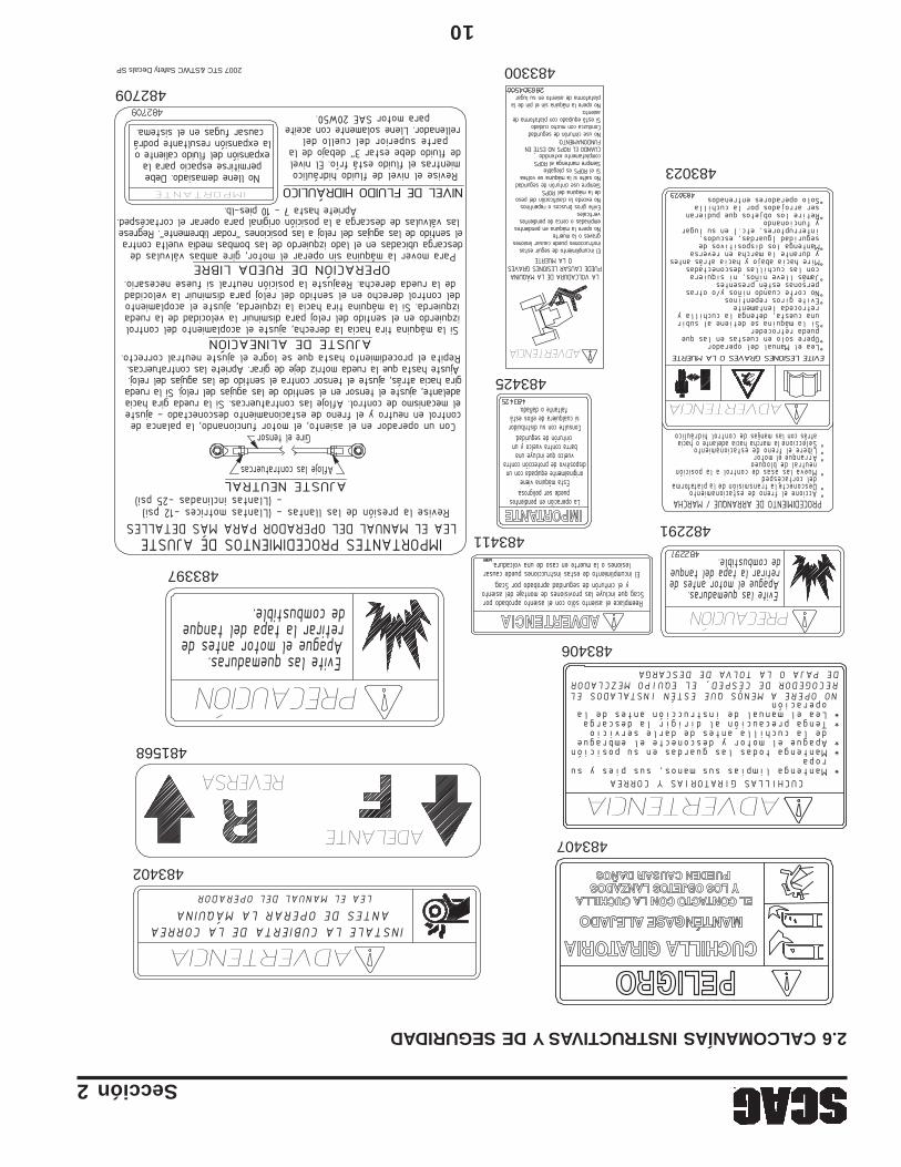
10
Sección 2
2.6 CALCOMANÍAS INSTRUCTIVAS Y DE SEGURIDAD
483407
483402
481568
483397
483406
482709
2007 STC &STWC Safety Decals SP
483023
482291
483300
483411
483425
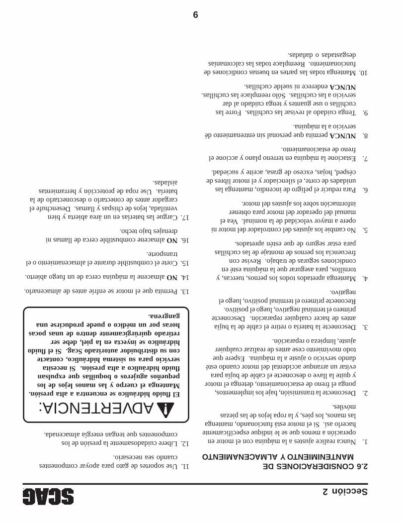
9
Sección 2
2.6 CONSIDERACIONES DEMANTENIMIENTO Y ALMACENAMIENTO
1.Nunca realice ajustes a la máquina con el motor enoperación a menos que se le indique específicamentehacerlo así. Si el motor está funcionando, mantengalas manos, los pies, y la ropa lejos de las piezasmóviles.
2.Desconecte la transmisión, baje los implementos,ponga el freno de estacionamiento, detenga el motory quite la llave o desconecte el cable de bujía paraevitar un arranque accidental del motor cuando estédando servicio o ajuste a la máquina. Espere quetodo movimiento cese antes de realizar cualquierajuste, limpieza o reparación.
3.Desconecte la batería o retire el cable de la bujíaantes de hacer cualquier reparación. Desconecteprimero el terminal negativo, luego el positivo.Reconecte primero el terminal positivo, luego elnegativo.
4.Mantenga apretados todos los pernos, tuercas, ytornillos, para asegurar que la máquina esté encondiciones seguras de trabajo. Revise confrecuencia los pernos de montaje de las cuchillaspara estar seguro de que estén apretados.
5.No cambie los ajustes del controlador del motor niopere a mayor velocidad de la nominal. Vea elmanual del operador del motor para obtenerinformación sobre los ajustes del motor.
6.Para reducir el peligro de incendio, mantenga lasunidades de corte, el silenciador y el motor libres decésped, hojas, exceso de grasa, aceite y suciedad.
7.Estacione la máquina en terreno plano y accione elfreno de estacionamiento.
8.NUNCA permita que personal sin entrenamiento déservicio a la máquina.
9.Tenga cuidado al revisar las cuchillas. Forre lascuchillas o use guantes y tenga cuidado al darservicio a las cuchillas. Sólo reemplace las cuchillas.NUNCA enderece ni suelde cuchillas.
10.Mantenga todas las partes en buenas condiciones defuncionamiento. Reemplace todas las calcomaníasdesgastadas o dañadas.
11.Use soportes de gato para apoyar componentescuando sea necesario.
12.Libere cuidadosamente la presión de loscomponentes que tengan energía almacenada.
13.Permita que el motor se enfríe antes de almacenarlo.
14.NO almacene la máquina cerca de un fuego abierto.
15.Corte el combustible durante el almacenamiento o eltransporte.
16.NO almacene combustible cerca de llamas nidrenajes bajo techo.
17.Cargue las baterías en un área abierta y bienventilada, lejos de chispas y llamas. Desenchufe elcargador antes de conectarlo o desconectarlo de labatería. Use ropa de protección y herramientasaisladas.
El fluido hidráulico se encuentra a alta presión.Mantenga el cuerpo y las manos lejos de lospequeños agujeros o boquillas que expulsanfluido hidráulico a alta presión. Si necesitaservicio para su sistema hidráulico, contactecon su distribuidor autorizado Scag. Si el fluidohidráulico se inyecta en la piel, debe serretirado quirúrgicamente dentro de unas pocashoras por un médico o puede producirse unagangrena.
ADVERTENCIA:
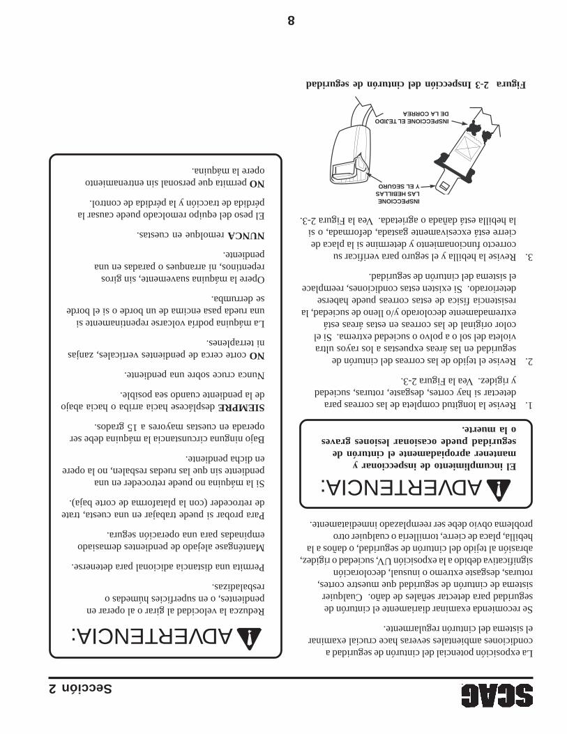
8
Sección 2
Figura 2-3 Inspección del cinturón de seguridad
INSPECCIONE EL TEJIDO DE LA CORREA
INSPECCIONE LAS HEBILLAS Y EL SEGURO
La exposición potencial del cinturón de seguridad acondiciones ambientales severas hace crucial examinarel sistema del cinturón regularmente.
Se recomienda examinar diariamente el cinturón deseguridad para detectar señales de daño. Cualquiersistema de cinturón de seguridad que muestre cortes,roturas, desgaste extremo o inusual, decoloraciónsignificativa debido a la exposición UV, suciedad o rigidez,abrasión al tejido del cinturón de seguridad, o daños a lahebilla, placa de cierre, tornillería o cualquier otroproblema obvio debe ser reemplazado inmediatamente.
1.Revise la longitud completa de las correas paradetectar si hay cortes, desgaste, roturas, suciedady rigidez. Vea la Figura 2-3.
2.Revise el tejido de las correas del cinturón deseguridad en las áreas expuestas a los rayos ultravioleta del sol o a polvo o suciedad extrema. Si elcolor original de las correas en estas áreas estáextremadamente decolorado y/o lleno de suciedad, laresistencia física de estas correas puede habersedeteriorado. Si existen estas condiciones, reemplaceel sistema del cinturón de seguridad.
3.Revise la hebilla y el seguro para verificar sucorrecto funcionamiento y determine si la placa decierre está excesivamente gastada, deformada, o sila hebilla está dañada o agrietada. Vea la Figura 2-3.
El incumplimiento de inspeccionar ymantener apropiadamente el cinturón deseguridad puede ocasionar lesiones graveso la muerte.
Reduzca la velocidad al girar o al operar enpendientes, o en superficies húmedas oresbaladizas.
Permita una distancia adicional para detenerse.
Manténgase alejado de pendientes demasiadoempinadas para una operación segura.
Para probar si puede trabajar en una cuesta, tratede retroceder (con la plataforma de corte baja).
Si la máquina no puede retroceder en unapendiente sin que las ruedas resbalen, no la opereen dicha pendiente.
Bajo ninguna circunstancia la máquina debe seroperada en cuestas mayores a 15 grados.
SIEMPRE desplácese hacia arriba o hacia abajode la pendiente cuando sea posible.
Nunca cruce sobre una pendiente.
NO corte cerca de pendientes verticales, zanjasni terraplenes.
La máquina podría volcarse repentinamente siuna rueda pasa encima de un borde o si el bordese derrumba.
Opere la máquina suavemente, sin girosrepentinos, ni arranques o paradas en unapendiente.
NUNCA remolque en cuestas.
El peso del equipo remolcado puede causar lapérdida de tracción y la pérdida de control.
NO permita que personal sin entrenamientoopere la máquina.
ADVERTENCIA:
ADVERTENCIA:
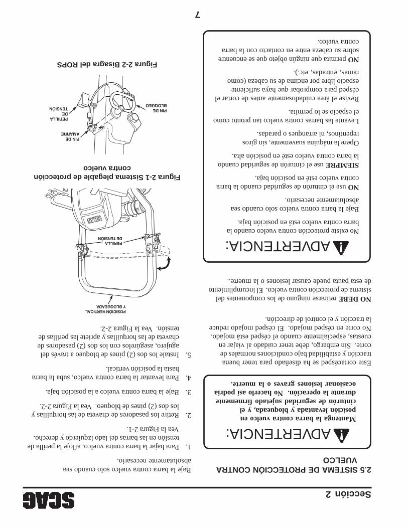
7
Figura 2-1 Sistema plegable de proteccióncontra vuelco
Figura 2-2 Bisagra del ROPS
PERILLA DE TENSIÓN
PIN DE AMARRE
PIN DE BLOQUEO
POSICIÓN VERTICAL Y BLOQUEADA
PERILLA DE TENSIÓN
2.5 SISTEMA DE PROTECCIÓN CONTRAVUELCO
Mantenga la barra contra vuelco enposición levantada y bloqueada, y elcinturón de seguridad sujetado firmementedurante la operación. No hacerlo así podríaocasionar lesiones graves o la muerte.
Este cortacésped se ha diseñado para tener buenatracción y estabilidad bajo condiciones normales decorte. Sin embargo, debe tener cuidado al viajar encuestas, especialmente cuando el césped está mojado.No corte en césped mojado. El césped mojado reducela tracción y el control de dirección.
NO DEBE retirarse ninguno de los componentes delsistema de protección contra vuelco. El incumplimientode esta pauta puede causar lesiones o la muerte..
No existe protección contra vuelco cuando labarra contra vuelco está en posición baja.
Baje la barra contra vuelco solo cuando seaabsolutamente necesario.
NO use el cinturón de seguridad cuando la barracontra vuelco esté en posición baja.
SIEMPRE use el cinturón de seguridad cuandola barra contra vuelco esté en posición alta.
Opere la máquina suavemente, sin girosrepentinos, ni arranques o paradas.
Levante las barras contra vuelco tan pronto comoel espacio se lo permita.
Revise el área cuidadosamente antes de cortar elcésped para comprobar que haya suficienteespacio libre por encima de su cabeza (comoramas, entradas, etc.).
NO permita que ningún objeto que se encuentresobre su cabeza entre en contacto con la barracontra vuelco.
Sección 2
Baje la barra contra vuelco solo cuando seaabsolutamente necesario.
1.Para bajar la barra contra vuelco, afloje la perilla detensión en las barras del lado izquierdo y derecho.Vea la Figura 2-1.
2.Retire los pasadores de chaveta de las horquillas ylos dos (2) pines de bloqueo. Vea la Figura 2-2.
3.Baje la barra contra vuelco a la posición baja.
4.Para levantar la barra contra vuelco, suba la barrahasta la posición vertical.
5.Instale los dos (2) pines de bloqueo a través delagujero, asegúrelos con los dos (2) pasadores dechaveta de las horquillas y apriete las perillas detensión. Vea la Figura 2-2.
ADVERTENCIA:
ADVERTENCIA:
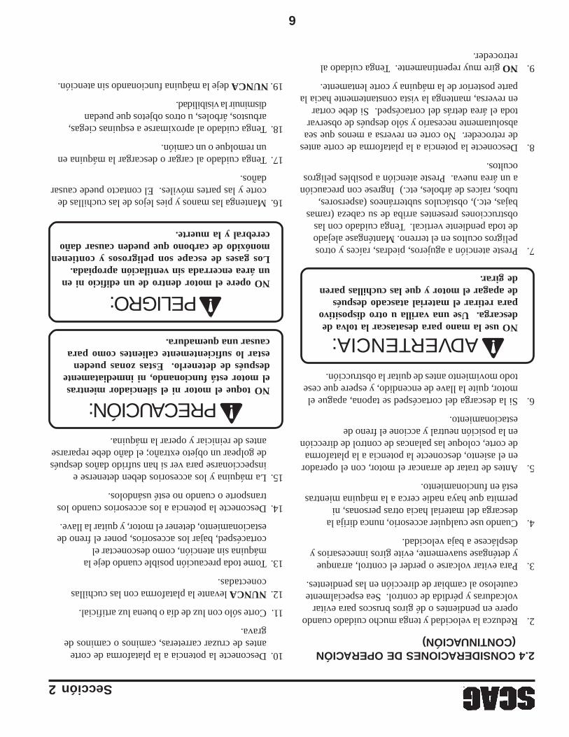
6
Sección 2
2.4 CONSIDERACIONES DE OPERACIÓN(CONTINUACIÓN)
2.Reduzca la velocidad y tenga mucho cuidado cuandoopere en pendientes o dé giros bruscos para evitarvolcaduras y pérdida de control. Sea especialmentecauteloso al cambiar de dirección en las pendientes.
3.Para evitar volcarse o perder el control, arranquey deténgase suavemente, evite giros innecesarios ydesplácese a baja velocidad.
4.Cuando use cualquier accesorio, nunca dirija ladescarga del material hacia otras personas, nipermita que haya nadie cerca a la máquina mientrasestá en funcionamiento.
5.Antes de tratar de arrancar el motor, con el operadoren el asiento, desconecte la potencia a la plataformade corte, coloque las palancas de control de direcciónen la posición neutral y accione el freno deestacionamiento.
6.Si la descarga del cortacésped se tapona, apague elmotor, quite la llave de encendido, y espere que cesetodo movimiento antes de quitar la obstrucción.
NO use la mano para desatascar la tolva dedescarga. Use una varilla u otro dispositivopara retirar el material atascado despuésde apagar el motor y que las cuchillas parende girar.
7.Preste atención a agujeros, piedras, raíces y otrospeligros ocultos en el terreno. Manténgase alejadode toda pendiente vertical. Tenga cuidado con lasobstrucciones presentes arriba de su cabeza (ramasbajas, etc.), obstáculos subterráneos (aspersores,tubos, raíces de árboles, etc.) Ingrese con precaucióna un área nueva. Preste atención a posibles peligrosocultos.
8.Desconecte la potencia a la plataforma de corte antesde retroceder. No corte en reversa a menos que seaabsolutamente necesario y sólo después de observartoda el área detrás del cortacésped. Si debe cortaren reversa, mantenga la vista constantemente hacia laparte posterior de la máquina y corte lentamente.
9.NO gire muy repentinamente. Tenga cuidado alretroceder.
10.Desconecte la potencia a la plataforma de corteantes de cruzar carreteras, caminos o caminos degrava.
11.Corte sólo con luz de día o buena luz artificial.
12.NUNCA levante la plataforma con las cuchillasconectadas.
13.Tome toda precaución posible cuando deje lamáquina sin atención, como desconectar elcortacésped, bajar los accesorios, poner el freno deestacionamiento, detener el motor, y quitar la llave.
14.Desconecte la potencia a los accesorios cuando lostransporte o cuando no esté usándolos.
15.La máquina y los accesorios deben detenerse einspeccionarse para ver si han sufrido daños despuésde golpear un objeto extraño; el daño debe repararseantes de reiniciar y operar la máquina.
NO toque el motor ni el silenciador mientrasel motor está funcionando, ni inmediatamentedespués de detenerlo. Estas zonas puedenestar lo suficientemente calientes como paracausar una quemadura.
NO opere el motor dentro de un edificio ni enun área encerrada sin ventilación apropiada.Los gases de escape son peligrosos y contienenmonóxido de carbono que pueden causar dañocerebral y la muerte.
16.Mantenga las manos y pies lejos de las cuchillas decorte y las partes móviles. El contacto puede causardaños.
17.Tenga cuidado al cargar o descargar la máquina enun remolque o un camión.
18.Tenga cuidado al aproximarse a esquinas ciegas,arbustos, árboles, u otros objetos que puedandisminuir la visibilidad.
19. NUNCA deje la máquina funcionando sin atención.
ADVERTENCIA:
PRECAUCIÓN:
PELIGRO:
5
Sección 2
12.NO agregue combustible a un motor en operación nia un motor caliente. Permita que el motor se enfríepor varios minutos antes de agregar el combustible.Nunca llene combustible bajo techo ni en unremolque cerrado.
13.Mantenga los objetos inflamables (cigarrillos,fósforos o cerillos, etc.), las llamas abiertas ychispas, lejos del tanque y el recipiente decombustible. Use sólo recipientes aprobados.
14.El equipo debe cumplir con los últimos requisitos deacuerdo con SAE J137 y/o ANSI/ASAE S279cuando sea manejado en caminos públicos.
-NOTA-
Si el cortacésped es conducido en caminospúblicos, debe cumplir los reglamentos estatales ylocales así como también los requisitos SAE J137y/o ANSI/ASAE S279. Contacte con susautoridades locales para informarse sobre lasnormas y los requisitos del equipo.
15.NO opere sin la tolva de descarga lateral instaladay en la posición baja o con un recogedor de céspedo placa desmenuzadora opcionales completamenteinstalados.
16.Verifique a intervalos frecuentes que los pernos demontaje de la cuchilla estén correctamente ajustados.
17.Asegúrese de que todas las conexiones hidráulicasestén apretadas y que todas las manguerashidráulicas y las líneas estén en buen estado antesde arrancar la máquina.
2.4 CONSIDERACIONES DE OPERACIÓN
1.Conozca la función de todos los controles y sepacómo detener el equipo rápidamente.
NO opere en pendientes empinadas. Para probar sipuede trabajar en una cuesta, trate de retroceder(con la plataforma de corte baja). Si la máquinapuede retroceder por la pendiente sin que las ruedasse resbalen, reduzca la velocidad y opere con extremocuidado. Bajo ninguna circunstancia la máquinadebe ser operada en cuestas mayores a 15 grados.SIEMPRE CUMPLA CON LAS OPERACIONESAPROBADAS POR OSHA.
7.Si el operador o mecánico no puede leer inglés oespañol, es responsabilidad del propietario explicarleseste material.
8.NO use ropa muy holgada. La ropa holgada, lasjoyas o el cabello largo podrían enredarse en partesmóviles. No opere la máquina llevando pantalonescortos; siempre lleve ropa de protección adecuada,incluyendo pantalones largos. Es recomendablellevar gafas de seguridad, zapatos de seguridad y uncasco, pues es requerido por algunos reglamentoslocales y normas del seguro.
Siempre use protectores auditivos. El operaresta máquina por períodos prolongados detiempo puede causar pérdida de la audición.
9.Mantenga la máquina y los accesorios en buenascondiciones de operación. Mantenga todas lasguardas y dispositivos de seguridad en su lugar.Si una guarda, un dispositivo de seguridad o unacalcomanía, están defectuosos o dañados, repáreloso reemplácelos antes de operar la máquina.
Esta máquina está equipada con un sistema debloqueo diseñado para evitar lesiones personalesal operador y a terceros. Esto se logra evitandoque el motor arranque a menos que la transmisiónde plataforma esté desconectada, el freno deestacionamiento accionado, las palancas de controlde dirección en la posición neutral y el operador enel asiento. El sistema apaga el motor si el operadordeja el asiento con la transmisión de plataformaaccionada y/o la palanca de control de dirección enuna posición diferente de la neutral y el freno deestacionamiento no accionado. Nunca opere elequipo con el sistema de bloqueo desconectado nifuncionando defectuosamente.
10.Asegúrese que los conmutadores de bloqueofuncionen correctamente.
11.El combustible es inflamable; manipúlelo concuidado. Llene el tanque de combustible al aire libre.Nunca lo llene bajo techo. Use un embudo paraevitar derrames. Limpie cualquier derrame antes dearrancar el motor.
ADVERTENCIA:
ADVERTENCIA:
ADVERTENCIA:

4
Sección 2
2.1 INTRODUCCIÓNSu cortacésped es tan seguro como el operador. El erroro descuido del operador puede ocasionar lesionespersonales graves o la muerte. El control de riesgos y laprevención de accidentes dependen del conocimiento, elinterés, la prudencia, y el entrenamiento apropiados delpersonal relacionado con la operación, el transporte,mantenimiento y almacenamiento del equipo. Cercióresede que cada operador esté entrenado apropiadamente ycompletamente familiarizado con todos los controles antesde operar el cortacésped. El propietario/usuario puedeevitar y es responsable de los accidentes o heridas que lesocurran a ellos mismos, a otras personas o a la propiedad.
LEA ESTE MANUAL DEL OPERADOR ANTES DETRATAR DE ARRANCAR SU CORTACÉSPED.
Hay disponible un manual de reemplazo en su distribuidorautorizado Scag o contactándose con Scag PowerEquipment, Service Department en P.O. Box 152,Mayville, WI 53050, o visitando su sitio web enwww.scag.com. Puede descargar el manual para sumáquina utilizando el modelo y el número de serie omediante el formulario de contacto para hacer su pedido.Indique el modelo y el número de serie completos de suproducto de Scag cuando solicite manuales de reemplazo.
2.2 PALABRAS DE SEÑALIZACIÓN
Este símbolo significa “¡Atención! ¡Alerta! ¡Hay unriesgo para su seguridad!” El símbolo se usa con lassiguientes palabras de señalización para llamar suatención sobre mensajes de seguridad localizados en lascalcomanías del equipo y a través de este manual. Elmensaje que sigue al símbolo contiene informaciónimportante sobre seguridad. ¡Para evitar posibleslesiones o la muerte, lea detalladamente el mensaje!Cerciórese de entender completamente las causas quepueden ocasionar lesiones o la muerte.
Palabra de señalización:
Es una palabra distintiva que se encuentra en lascalcomanías de seguridad del equipo y a través de estemanual para alertar sobre la existencia y el grado de unacondición de peligro.
La palabra de señalización “WARNING”(ADVERTENCIA) indica que existe un riesgo en ocerca de la máquina que puede ocasionar lesiones o lamuerte si no se toman las precauciones debidas.
La palabra de señalización “DANGER” (PELIGRO)indica que existe una situación extremadamente peligrosaen o cerca de la máquina, que tiene altas probabilidadesde ocasionar la muerte o una lesión irreparable si no setoman las precauciones apropiadas.
La palabra de señalización “CAUTION”(PRECAUCIÓN) es un recordatorio de que se debenseguir prácticas seguras en o cerca de la máquina y quede no seguirse, se pueden ocasionar lesiones personales.
Su seguridad y la de los demás dependen en gran parte deque usted conozca y comprenda todos los procedimientosy las prácticas de operación correcta de esta máquina.
2.3 CONSIDERACIONES PREVIAS A LAOPERACIÓN
1.NUNCA permita que niños operen este cortacésped.No permita que adultos operen esta máquina sininstrucciones apropiadas.
2.NO corte cuándo niños y/o otras personas esténpresentes. Mantenga a los niños fuera del área decorte y al cuidado atento de un adulto responsabledistinto del operador. Esté atento y apague lamáquina si un niño ingresa al área.
3.NO permita que los niños se suban o jueguen en lamáquina, no es un juguete.
4.Retire del área que debe ser cortada todos losobjetos que pudieran ser recogidos y arrojados porlas cuchillas.
5.NO lleve pasajeros.
6.NO opere el equipo bajo la influencia de alcoholo drogas.
INFORMACIÓN DE SEGURIDAD
PELIGRO:
ADVERTENCIA:
PRECAUCIÓN:
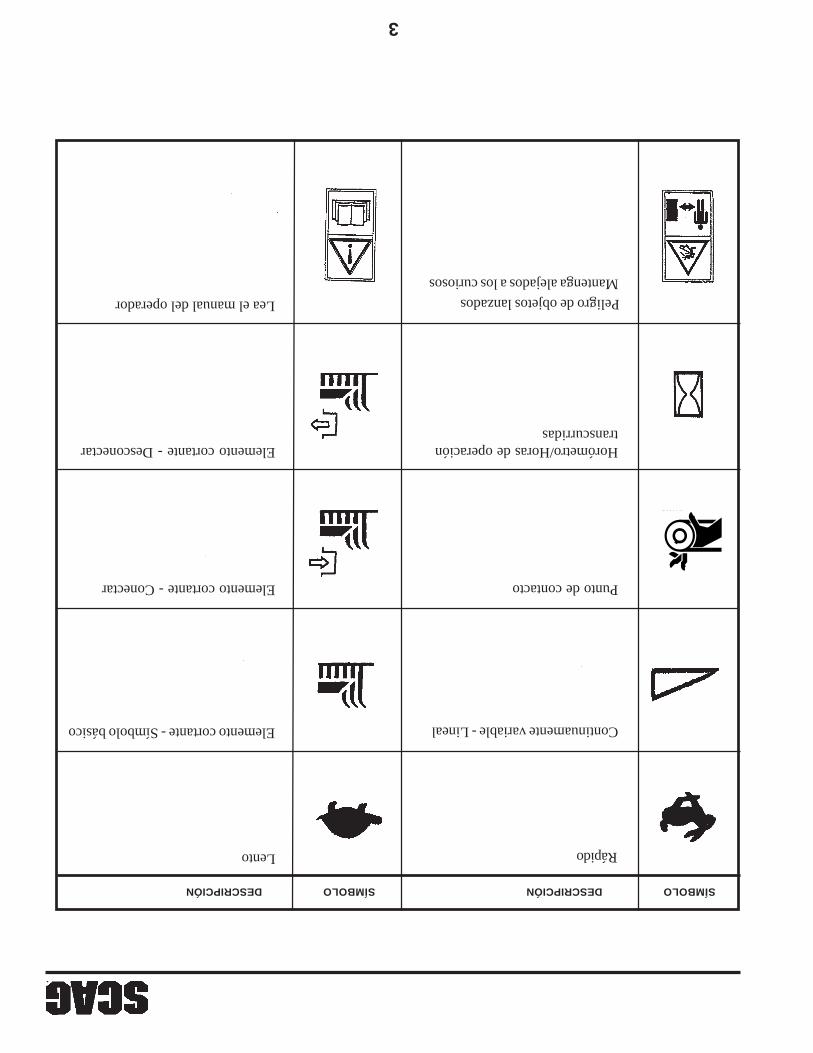
3
Lento Rápido
Elemento cortante - Conectar
Elemento cortante - Símbolo básico
Elemento cortante - Desconectar
Continuamente variable - Lineal
Lea el manual del operador
Mantenga alejados a los curiosos
Punto de contacto
481039S
SÍMBOLODESCRIPCIÓNSÍMBOLODESCRIPCIÓN
Horómetro/Horas de operacióntranscurridas
Peligro de objetos lanzados
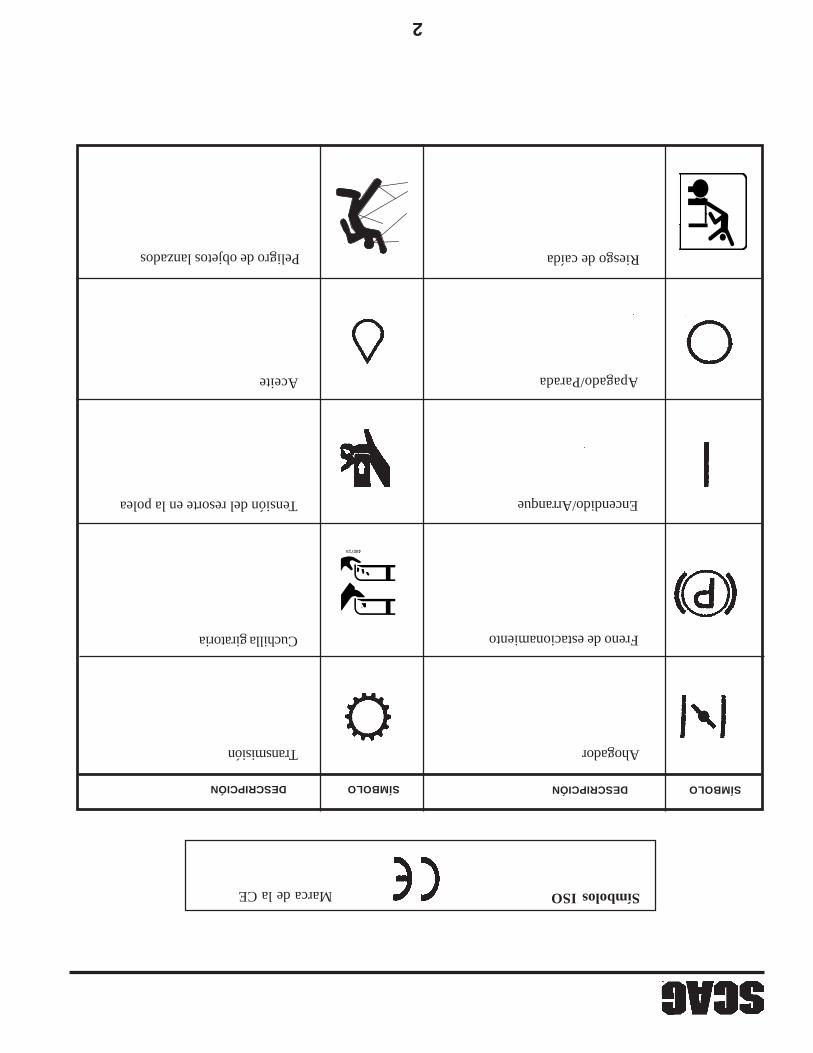
2
Marca de la CE
Transmisión Ahogador
Encendido/ArranqueTensión del resorte en la polea
Aceite Apagado/Parada
SÍMBOLODESCRIPCIÓN SÍMBOLODESCRIPCIÓN
Símbolos ISO
Cuchilla giratoria
48071S
Freno de estacionamiento
WARNINGFALLING HAZARD
USE ONLY SCAG APPROVEDRIDING ATTACHMENTS
SEE OPERATOR'S MANUAL481109
Riesgo de caída Peligro de objetos lanzados
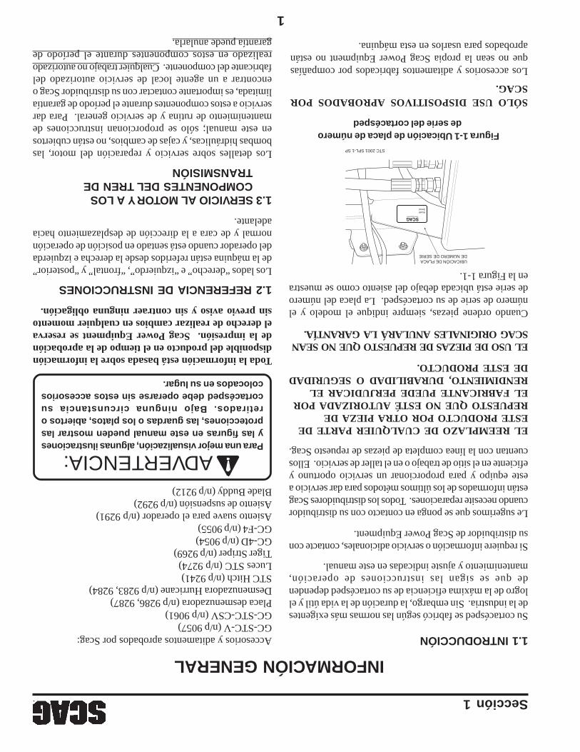
1
Accesorios y aditamentos aprobados por Scag:GC-STC-V (n/p 9057)GC-STC-CSV (n/p 9061)Placa desmenuzadora (n/p 9286, 9287)Desmenuzadora Hurricane (n/p 9283, 9284)STC Hitch (n/p 9241)Luces STC (n/p 9274)Tiger Striper (n/p 9269)GC-4D (n/p 9054)GC-F4 (n/p 9055)Asiento suave para el operador (n/p 9291)Asiento de suspensión (n/p 9292)Blade Buddy (n/p 9212)
INFORMACIÓN GENERAL1.1 INTRODUCCIÓN
Su cortacésped se fabricó según las normas más exigentesde la industria. Sin embargo, la duración de la vida útil y ellogro de la máxima eficiencia de su cortacésped dependende que se sigan las instrucciones de operación,mantenimiento y ajuste indicadas en este manual.
Si requiere información o servicio adicionales, contacte consu distribuidor de Scag Power Equipment.
Le sugerimos que se ponga en contacto con su distribuidorcuando necesite reparaciones. Todos los distribuidores Scagestán informados de los últimos métodos para dar servicio aeste equipo y para proporcionar un servicio oportuno yeficiente en el sitio de trabajo o en el taller de servicio. Elloscuentan con la línea completa de piezas de repuesto Scag.
EL REEMPLAZO DE CUALQUIER PARTE DEESTE PRODUCTO POR OTRA PIEZA DEREPUESTO QUE NO ESTÉ AUTORIZADA POREL FABRICANTE PUEDE PERJUDICAR ELRENDIMIENTO, DURABILIDAD O SEGURIDADDE ESTE PRODUCTO.
EL USO DE PIEZAS DE REPUESTO QUE NO SEANSCAG ORIGINALES ANULARÁ LA GARANTÍA.
Cuando ordene piezas, siempre indique el modelo y elnúmero de serie de su cortacésped. La placa del númerode serie está ubicada debajo del asiento como se muestraen la Figura 1-1.
Para una mejor visualización, algunas ilustracionesy las figuras en este manual pueden mostrar lasprotecciones, las guardas o los platos, abiertos oretirados. Bajo ninguna circunstancia sucortacésped debe operarse sin estos accesorioscolocados en su lugar.
Toda la información está basada sobre la informacióndisponible del producto en el tiempo de la aprobaciónde la impresión. Scag Power Equipment se reservael derecho de realizar cambios en cualquier momentosin previo aviso y sin contraer ninguna obligación.
1.2 REFERENCIA DE INSTRUCCIONES
Los lados “derecho” e “izquierdo”, “frontal” y “posterior”de la máquina están referidos desde la derecha e izquierdadel operador cuando está sentado en posición de operaciónnormal y de cara a la dirección de desplazamiento haciaadelante.
1.3 SERVICIO AL MOTOR Y A LOSCOMPONENTES DEL TREN DETRANSMISIÓN
Los detalles sobre servicio y reparación del motor, lasbombas hidráulicas, y cajas de cambios, no están cubiertosen este manual; sólo se proporcionan instrucciones demantenimiento de rutina y de servicio general. Para darservicio a estos componentes durante el período de garantíalimitada, es importante contactar con su distribuidor Scag oencontrar a un agente local de servicio autorizado delfabricante del componente. Cualquier trabajo no autorizadorealizado en estos componentes durante el período degarantía puede anularla.
Sección 1
Figura 1-1 Ubicación de placa de número de serie del cortacésped
ModelSerial
SCAG Power Equipment
STC 2001 SPL-1 SP
UBICACIÓN DE PLACA DE NÚMERO DE SERIE
SÓLO USE DISPOSITIVOS APROBADOS PORSCAG.
Los accesorios y aditamentos fabricados por compañíasque no sean la propia Scag Power Equipment no estánaprobados para usarlos en esta máquina.
ADVERTENCIA:

II
TABLA DE CONTENIDO (CONTINUACIÓN) TEMAPÁGINA
Sección 6 - Ajustes6.1Ajuste del Freno de estacionamiento....................................................................................236.2Ajustes de desplazamiento....................................................................................................246.3Ajustes de los controles de aceleración y estrangulación.....................................................256.4Ajuste de la correa................................................................................................................256.5Alineación de la correa.........................................................................................................256.6Ajustes de la plataforma de corte.........................................................................................26
Sección 7 - Mantenimiento7.1Tabla de mantenimiento........................................................................................................297.2Lubricación de puntos de conexión.......................................................................................307.3Sistema hidráulico.................................................................................................................327.4Aceite del motor...................................................................................................................337.5Sistema de combustible del motor.........................................................................................347.6Filtro de aire del motor..........................................................................................................347.7Batería..................................................................................................................................357.8Correas de transmisión.........................................................................................................367.9Cuchillas de corte.................................................................................................................367.10Llantas..................................................................................................................................377.11Cuerpo, plataforma y tapicería..............................................................................................37
Sección 8 - Piezas de repuestoPlataformas de corte STC48A y STC52A...............................................................................38-39Controles de plataforma de corte.............................................................................................40-41Componentes de láminas metálicas..........................................................................................42-43Sistema de protección contra vuelco STC................................................................................44-45Componentes del sistema de transmisión.................................................................................46-47Motor y accesorios - Kawasaki y Kohler................................................................................48-49Motor y accesorios - Honda.....................................................................................................50-51Componentes de dirección........................................................................................................52-53Componentes de frenos............................................................................................................54-55Sistemas de combustible e hidráulico........................................................................................56-57Sistema eléctrico.......................................................................................................................58-59Bomba hidráulica (BDP-10A)..................................................................................................60-61Calcomanías de repuesto..........................................................................................................62-63Esquema eléctrico..........................................................................................................................64Declaración de garantía........................................................Después de la Lista de partes ilustrada

I
TABLA DE CONTENIDO
4.14Remolque..............................................................................................................................194.15Ajuste de las palancas de dirección......................................................................................19
TEMAPÁGINA
Sección 1 - Información general1.1Introducción............................................................................................................................11.2Referencia de instrucciones....................................................................................................11.3Servicio al motor y a los componentes del tren de transmisión..............................................11.3Símbolos..............................................................................................................................2-3
Sección 2 - Información de seguridad2.1Introducción............................................................................................................................42.2Palabras de señalización.........................................................................................................42.3Consideraciones previas a la operación..................................................................................42.4Consideraciones de operación................................................................................................52.5Sistema de protección contra vuelco......................................................................................72.6Consideraciones de mantenimiento.........................................................................................92.7Calcomanías instructivas y de seguridad..............................................................................10
Sección 3 - Especificaciones...............................................................................................11-12
Sección 4 - Instrucciones de operación4.1Identificación de controles e instrumentos............................................................................134.2Sistema de bloqueo de seguridad..........................................................................................144.3Procedimientos de arranque inicial.......................................................................................154.4Arranque del motor...............................................................................................................154.5Desplazamiento en el terreno y dirección.............................................................................154.6Conexión de la transmisión de plataforma............................................................................164.7Operación en una cuesta......................................................................................................174-8Estacionamiento del cortacésped..........................................................................................174.9Después de la operación.......................................................................................................174.10Retiro del material atascado.................................................................................................184.11Desplazamiento del cortacésped con el motor detenido.......................................................184.12Recomendaciones de corte de césped..................................................................................184.13Ajuste de la altura de corte...................................................................................................18
Sección 5 - Identificación de fallas en las condiciones de corte....................................20-22

EL INCUMPLIMIENTO DE LAS PRÁCTICAS SEGURAS DEOPERACIÓN PUEDE RESULTAR EN LESIONES GRAVES.
RECUERDE - ¡SU CORTACÉSPED ES TAN SEGURO COMOEL OPERADOR!
El control de riesgos y la prevención de accidentes dependen del conocimiento, elinterés, la prudencia, y el entrenamiento apropiados del personal relacionado conla operación, el transporte, mantenimiento y almacenamiento del equipo.
Este manual cubre las instrucciones de operación y la lista de partes ilustradas para:
STC48V-19KAIcon números de serie desde C6000001 a C6099999STC48V-23CVcon números de serie desde C6200001 a C6299999STC52V-23KAcon números de serie desde C6300001 a C6399999STC52V-24HNcon números de serie desde C6400001 a C6499999SMTC-48Vcon números de serie desde C7000001 a C7099999SMWC-52Vcon números de serie desde C7100001 a C7199999
Cuando se refiera a este producto siempre use el número deserie completo que aparece en la etiqueta de número de serie.
ADVERTENCIA:
* Mantenga todas las guardas en su posición, especialmente la de latolva de descarga de césped.
* Antes de realizar cualquier mantenimiento o servicio, detenga lamáquina y quite el cable de la bujía y la llave de encendido.
* Si un mecanismo se atasca, detenga el motor antes de limpiar.* Mantenga las manos, los pies y la ropa lejos de las partes móviles.* Lea este manual completamente así como cualquier otro manual
proporcionado con su cortacésped.* Mantenga a otras personas alejadas del tractor (sólo una persona
debe usarlo a la vez).* NO opere en pendientes empinadas. Para probar si puede trabajar
en una cuesta, trate de retroceder (con la plataforma de corte baja).Si la máquina puede retroceder por la pendiente sin que las ruedasse resbalen, reduzca la velocidad y opere con extremo cuidado.Bajo ninguna circunstancia la máquina debe ser operada en cuestasmayores a 15 grados. SIEMPRE CUMPLA CON LASOPERACIONES APROBADAS POR OSHA.
* No corte en césped mojado. El césped mojado reduce la tracción yel control de dirección.
MODELO STC
MANUAL DEL OPERADOR
ESTE MANUAL CONTIENE LASINSTRUCCIONES DE OPERACIÓN Y LAINFORMACIÓN DE SEGURIDAD PARA SUCORTACÉSPED SCAG. LA LECTURA DE ESTEMANUAL LE PUEDE AYUDAR EN ELMANTENIMIENTO Y LOS PROCEDIMIENTOSDE AJUSTE A FIN DE MANTENER SUCORTACÉSPED TRABAJANDO A LA MÁXIMAEFICIENCIA. LOS MODELOS ESPECÍFICOSCUBIERTOS POR ESTE MANUAL ESTÁNINDICADOS EN LA CUBIERTA INTERIOR.ANTES DE OPERAR SU MÁQUINA, LEA TODALA INFORMACIÓN INCLUIDA.
PARTE Nº 03194IMPRESO EN 7/2006IMPRESO EN EE.UU.
© 2006Scag Power EquipmentDIVISION OF METALCRAFT OF MAYVILLE, INC.
Recommended