1998-2004 SUSPENSION
Front - Passat
IDENTIFICATION
IDENTIFYING VEHICLE SUSPENSION
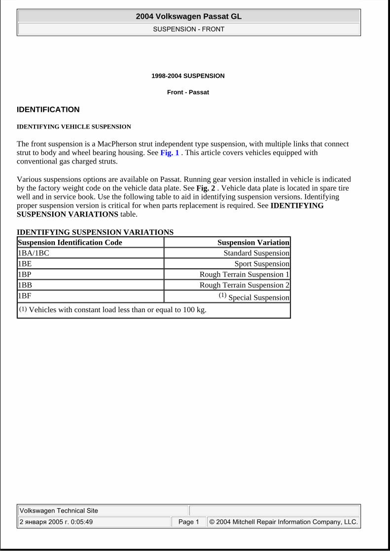
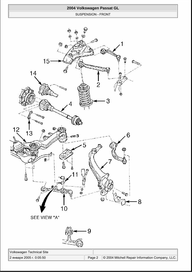
The front suspension is a MacPherson strut independent type suspension, with multiple links that connect strut to body and wheel bearing housing. See Fig. 1 . This article covers vehicles equipped with conventional gas charged struts.
Various suspensions options are available on Passat. Running gear version installed in vehicle is indicated by the factory weight code on the vehicle data plate. See Fig. 2 . Vehicle data plate is located in spare tire well and in service book. Use the following table to aid in identifying suspension versions. Identifying proper suspension version is critical for when parts replacement is required. See IDENTIFYING SUSPENSION VARIATIONS table.
IDENTIFYING SUSPENSION VARIATIONS Suspension Identification Code Suspension Variation 1BA/1BC Standard Suspension 1BE Sport Suspension 1BP Rough Terrain Suspension 1 1BB Rough Terrain Suspension 2 1BF (1) Special Suspension (1) Vehicles with constant load less than or equal to 100 kg.
2004 Volkswagen Passat GL
SUSPENSION - FRONT
Volkswagen Technical Site
2 января 2005 г. 0:05:49 Page 1 © 2004 Mitchell Repair Information Company, LLC.
2004 Volkswagen Passat GL
SUSPENSION - FRONT
Volkswagen Technical Site
2 января 2005 г. 0:05:50 Page 2 © 2004 Mitchell Repair Information Company, LLC.
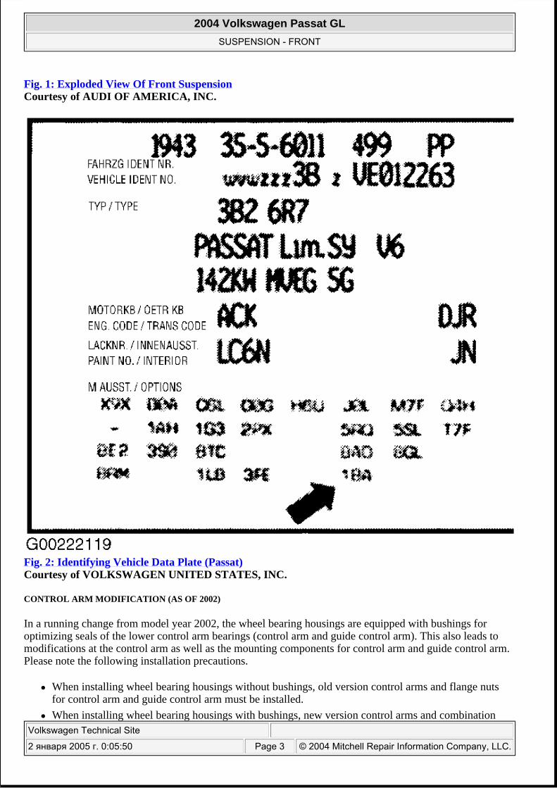
Fig. 1: Exploded View Of Front Suspension Courtesy of AUDI OF AMERICA, INC.
Fig. 2: Identifying Vehicle Data Plate (Passat) Courtesy of VOLKSWAGEN UNITED STATES, INC.
CONTROL ARM MODIFICATION (AS OF 2002)
In a running change from model year 2002, the wheel bearing housings are equipped with bushings for optimizing seals of the lower control arm bearings (control arm and guide control arm). This also leads to modifications at the control arm as well as the mounting components for control arm and guide control arm. Please note the following installation precautions.
When installing wheel bearing housings without bushings, old version control arms and flange nuts for control arm and guide control arm must be installed. When installing wheel bearing housings with bushings, new version control arms and combination
2004 Volkswagen Passat GL
SUSPENSION - FRONT
Volkswagen Technical Site
2 января 2005 г. 0:05:50 Page 3 © 2004 Mitchell Repair Information Company, LLC.
nuts for control arms and guide control arms must be installed. If only the control arm is replaced, a control arm of the old version must be replaced again by a control arm of the old version and a new version control arm is to be treated accordingly.
The following are to be used for control arm and guide control arm mounting parts:
Old version control arm use flange nut New version control arm use combination nut
CONNECTING LINK FOR STABILIZER BAR MODIFICATION
The ball joint in the connecting has been changed to a rubber mounting. The lower control arm was also slightly modified. Connecting with ball joint (1) is no longer installed on vehicles beginning with vehicle identification No. 3-B-X P-213 727. See Fig. 20 . Lower control arm (2) to stabilizer bar (6) was modified.
Only modified lower control arm is still supplied as a spare part. This lower control arm can also be installed in vehicles produced prior to vehicle identification No. 3-B-X P-213 727. In this case, the clamp (4) must also be used. Clamp is not installed in vehicles beginning with vehicle identification No. 3-B-X P-213 727. See Fig. 21 .
WHEEL BEARING HOUSING MODIFICATIONS (AS OF 2002)
In a running change from model year 2002, the wheel bearing housings are equipped with bushings for optimizing seals of the lower control arm bearings and guide control arm. Mixed installation of wheel bearing housings with and without bushings is permissible. Please not the following precautions:
When installing wheel bearing housings with bushings, the respective control arms (new version) and mounting components of the control arm as well as guide control arm must be used or replaced. The flange nuts must be replaced with combination nuts on mounting components. Guide control arms must not be replaced. Conventional flange nuts should be installed on vehicles with wheel bearing housings without bushings and control arms of old design. Replacement of bushings is not permitted. Replace wheel bearing housing in case of damage.
DESCRIPTION
VEHICLES WITH GAS DISCHARGE HEADLIGHTS
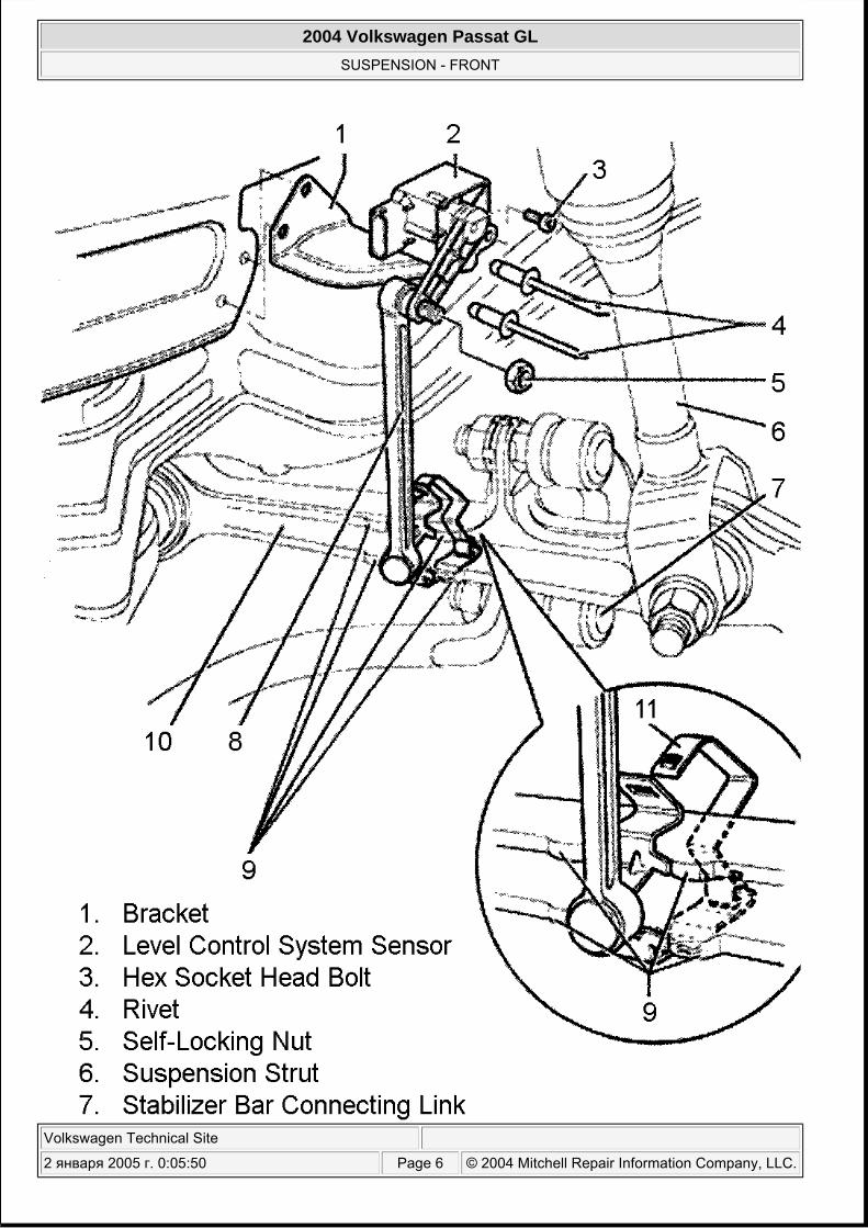
Vehicles with gas discharge headlights with automatic headlight range control comes standard. For its operation, the automatic headlight range control requires information about spring compression and rebound at the front and rear axles. For this, the position of the left lower control arm in relation to the structure is transferred over a connecting link to the left front level control system sensor. See Fig. 3 .
This transmits electrical signals to headlight range control module. These signals are transmitted to the control module from the left rear level control system sensor at the rear axle. These signals are required to determine vehicle level. The automatic headlight range control reacts independently to changes in vehicle level. The vehicle level can change in the following situations:
Towing a trailer
2004 Volkswagen Passat GL
SUSPENSION - FRONT
Volkswagen Technical Site
2 января 2005 г. 0:05:50 Page 4 © 2004 Mitchell Repair Information Company, LLC.
Different load conditions (vehicle empty, vehicle partially or fully loaded) Slow or fast driving habit
2004 Volkswagen Passat GL
SUSPENSION - FRONT
Volkswagen Technical Site
2 января 2005 г. 0:05:50 Page 5 © 2004 Mitchell Repair Information Company, LLC.
2004 Volkswagen Passat GL
SUSPENSION - FRONT
Volkswagen Technical Site
2 января 2005 г. 0:05:50 Page 6 © 2004 Mitchell Repair Information Company, LLC.
Fig. 3: Identifying Front Height Sensor & Link Courtesy of AUDI OF AMERICA, INC.
ADJUSTMENTS
WHEEL ALIGNMENT SPECIFICATIONS & PROCEDURES
WHEEL BEARING
INSPECTION
BALL JOINT CHECKING
Raise and support vehicle. Inspect ball joints for damaged rubber boots and vertical ball joint play. Procedure and wear tolerance are not available from manufacturer. When servicing ball joints, mark ball joint mounting position before removing to avoid changing camber setting.
REMOVAL & INSTALLATION
GUIDE CONTROL ARM (FWD)
Removal
1. Raise and support vehicle. Remove wheel assembly. See Fig. 1 . 2.
Remove guide control arm ball joint nut. Using Press Tool (3287A) or equivalent, press guide control arm from wheel bearing housing. Be careful not to damage CV boot. See Fig. 4 .
NOTE: See SPECIFICATIONS & PROCEDURES - PASSAT article in WHEEL ALIGNMENT.
NOTE: Wheel bearing is pressed into bearing housing. No adjustment is required.
NOTE: When drive axle is removed vehicle must not be moved. Moving vehicle without driveshaft will damage wheel bearing. If vehicle must be moved, temporarily install outer constant velocity joint in place of drive axle.
NOTE: Bonded rubber bushings can only be turned to a limited extent. Bolted connections should only be torqued to specification once vehicle is resting on its own weight.
NOTE: Special tools as needed, are identified in illustrations under SPECIAL TOOLS .
NOTE: Manufacturer recommends using NEW guide control arm ball joint nut and inner mounting bolt and nut during installation.
2004 Volkswagen Passat GL
SUSPENSION - FRONT
Volkswagen Technical Site
2 января 2005 г. 0:05:50 Page 7 © 2004 Mitchell Repair Information Company, LLC.
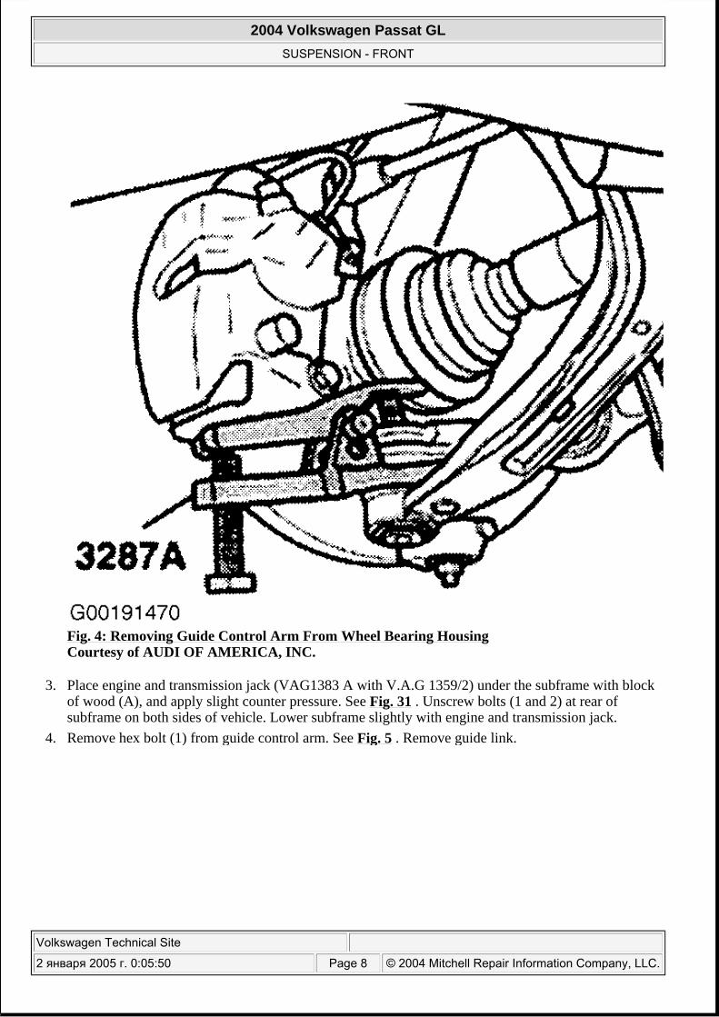
Fig. 4: Removing Guide Control Arm From Wheel Bearing Housing Courtesy of AUDI OF AMERICA, INC.
3. Place engine and transmission jack (VAG1383 A with V.A.G 1359/2) under the subframe with block of wood (A), and apply slight counter pressure. See Fig. 31 . Unscrew bolts (1 and 2) at rear of subframe on both sides of vehicle. Lower subframe slightly with engine and transmission jack.
4. Remove hex bolt (1) from guide control arm. See Fig. 5 . Remove guide link.
2004 Volkswagen Passat GL
SUSPENSION - FRONT
Volkswagen Technical Site
2 января 2005 г. 0:05:50 Page 8 © 2004 Mitchell Repair Information Company, LLC.
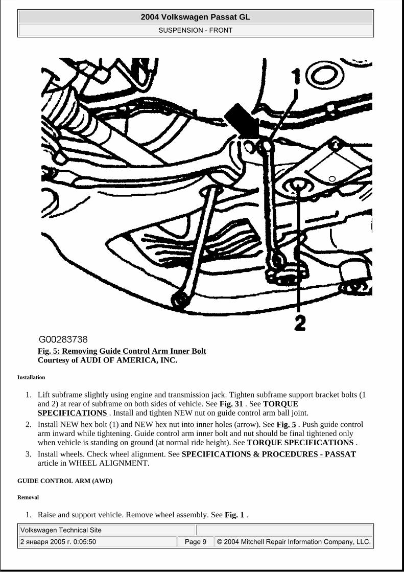
Fig. 5: Removing Guide Control Arm Inner Bolt Courtesy of AUDI OF AMERICA, INC.
Installation
1. Lift subframe slightly using engine and transmission jack. Tighten subframe support bracket bolts (1 and 2) at rear of subframe on both sides of vehicle. See Fig. 31 . See TORQUE SPECIFICATIONS . Install and tighten NEW nut on guide control arm ball joint.
2. Install NEW hex bolt (1) and NEW hex nut into inner holes (arrow). See Fig. 5 . Push guide control arm inward while tightening. Guide control arm inner bolt and nut should be final tightened only when vehicle is standing on ground (at normal ride height). See TORQUE SPECIFICATIONS .
3. Install wheels. Check wheel alignment. See SPECIFICATIONS & PROCEDURES - PASSAT article in WHEEL ALIGNMENT.
GUIDE CONTROL ARM (AWD)
Removal
1. Raise and support vehicle. Remove wheel assembly. See Fig. 1 .
2004 Volkswagen Passat GL
SUSPENSION - FRONT
Volkswagen Technical Site
2 января 2005 г. 0:05:50 Page 9 © 2004 Mitchell Repair Information Company, LLC.
2.
Placing mating marks on driveshaft flange and transmission mating flange. Remove self-locking bolts. Separate driveshaft from transmission.
3.
Remove guide control arm ball joint nut. Using Press Tool (3287A) or equivalent, press guide control arm from wheel bearing housing. Be careful not to damage CV boot. See Fig. 4 .
4. Place engine and transmission jack (VAG1383 A with V.A.G 1359/2) under the subframe with block of wood (A), and apply slight counter pressure. See Fig. 31 . Unscrew bolts (1 and 2) at rear of subframe on both sides of vehicle. Lower subframe slightly with engine and transmission jack.
5. Remove hex bolt (1) from guide control arm. See Fig. 5 . Remove guide control arm.
Installation
1. Lift subframe slightly using engine and transmission jack. Tighten subframe support bracket bolts (1 and 2) at rear of subframe on both sides of vehicle. See Fig. 31 . See TORQUE SPECIFICATIONS . Install and tighten NEW nut on guide control arm ball joint.
2. Install NEW hex bolt (1) and NEW hex nut into inner holes (arrow). See Fig. 5 . Push guide control arm inward while tightening. Guide control arm inner bolt and nut should be final tightened only when vehicle is standing on ground (at normal ride height). See TORQUE SPECIFICATIONS .
3. Clean transmission flange holes. Install driveshaft to transmission aligning mating marks. Install and tighten NEW self-locking bolts.
4. Install wheels. Check wheel alignment. See SPECIFICATIONS & PROCEDURES - PASSAT article in WHEEL ALIGNMENT.
GUIDE CONTROL ARM BUSHINGS
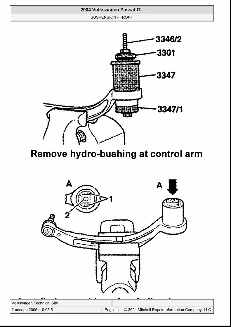
1. Remove guide control arm from vehicle. 2. Mount guide control arm in soft jawed vise. Using Bushing Remover/Installer Kit (3346, 3347 &
3301) or equivalent, remove and install bushings as shown in illustrations. See Fig. 6 and Fig. 7 .
CAUTION: Manufacturer recommends replacing driveshaft flange self-locking bolts.
NOTE: Manufacturer recommends using NEW guide control arm ball joint nut and inner mounting bolt and nut during installation.
2004 Volkswagen Passat GL
SUSPENSION - FRONT
Volkswagen Technical Site
2 января 2005 г. 0:05:51 Page 10 © 2004 Mitchell Repair Information Company, LLC.
2004 Volkswagen Passat GL
SUSPENSION - FRONT
Volkswagen Technical Site
2 января 2005 г. 0:05:51 Page 11 © 2004 Mitchell Repair Information Company, LLC.
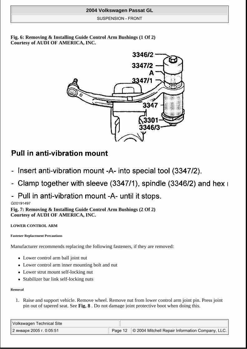
Fig. 6: Removing & Installing Guide Control Arm Bushings (1 Of 2) Courtesy of AUDI OF AMERICA, INC.
Fig. 7: Removing & Installing Guide Control Arm Bushings (2 Of 2) Courtesy of AUDI OF AMERICA, INC.
LOWER CONTROL ARM
Fastener Replacement Precautions
Manufacturer recommends replacing the following fasteners, if they are removed:
Lower control arm ball joint nut Lower control arm inner mounting bolt and nut Lower strut mount self-locking nut Stabilizer bar link self-locking nuts
Removal
1. Raise and support vehicle. Remove wheel. Remove nut from lower control arm joint pin. Press joint pin out of tapered seat. See Fig. 8 . Do not damage joint protective boot when doing this.
2004 Volkswagen Passat GL
SUSPENSION - FRONT
Volkswagen Technical Site
2 января 2005 г. 0:05:51 Page 12 © 2004 Mitchell Repair Information Company, LLC.
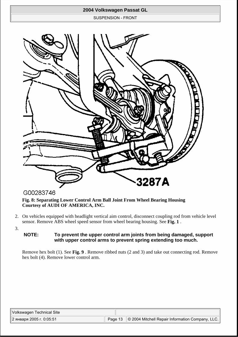
Fig. 8: Separating Lower Control Arm Ball Joint From Wheel Bearing Housing Courtesy of AUDI OF AMERICA, INC.
2. On vehicles equipped with headlight vertical aim control, disconnect coupling rod from vehicle level sensor. Remove ABS wheel speed sensor from wheel bearing housing. See Fig. 1 .
3.
Remove hex bolt (1). See Fig. 9 . Remove ribbed nuts (2 and 3) and take out connecting rod. Remove hex bolt (4). Remove lower control arm.
NOTE: To prevent the upper control arm joints from being damaged, support with upper control arms to prevent spring extending too much.
2004 Volkswagen Passat GL
SUSPENSION - FRONT
Volkswagen Technical Site
2 января 2005 г. 0:05:51 Page 13 © 2004 Mitchell Repair Information Company, LLC.
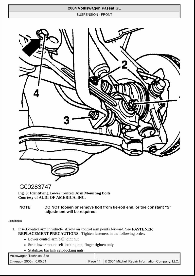
Fig. 9: Identifying Lower Control Arm Mounting Bolts Courtesy of AUDI OF AMERICA, INC.
Installation
1. Insert control arm in vehicle. Arrow on control arm points forward. See FASTENER REPLACEMENT PRECAUTIONS . Tighten fasteners in the following order:
Lower control arm ball joint nut Strut lower mount self-locking nut, finger tighten only Stabilizer bar link self-locking nuts
NOTE: DO NOT loosen or remove bolt from tie-rod end, or toe constant "S" adjustment will be required.
2004 Volkswagen Passat GL
SUSPENSION - FRONT
Volkswagen Technical Site
2 января 2005 г. 0:05:51 Page 14 © 2004 Mitchell Repair Information Company, LLC.
Lower control arm inner mounting nut/bolt, finger tighten only Push control arm inward while tightening. Wheel mounting .
2. On vehicles with automatic headlight range control, install clamp for connecting rod for left front level control system sensor to control arm. During installation, observe installing position of clamp on control arm.
3. On all models, install wheels. 4. Parts that have bonded rubber bushing should be torqued only when vehicle is standing on ground.
See TORQUE SPECIFICATIONS . 5. Check wheel alignment. See SPECIFICATIONS & PROCEDURES - PASSAT article in WHEEL
ALIGNMENT.
LOWER CONTROL ARM BUSHINGS
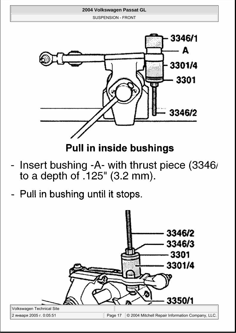
1. Mount lower control arm in soft jawed vise. Using Bushing Remover/Installer Kit (3346 & 3301) or equivalent, remove and install bushings as shown in illustrations. See Fig. 10 -Fig. 12 .
NOTE: Final tighten strut lower mount self-locking nut and lower control arm inner mounting nut/bolt with full weight of vehicle on ground (curb height).
2004 Volkswagen Passat GL
SUSPENSION - FRONT
Volkswagen Technical Site
2 января 2005 г. 0:05:51 Page 15 © 2004 Mitchell Repair Information Company, LLC.
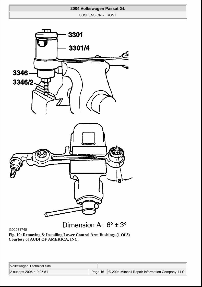
Fig. 10: Removing & Installing Lower Control Arm Bushings (1 Of 3) Courtesy of AUDI OF AMERICA, INC.
2004 Volkswagen Passat GL
SUSPENSION - FRONT
Volkswagen Technical Site
2 января 2005 г. 0:05:51 Page 16 © 2004 Mitchell Repair Information Company, LLC.
2004 Volkswagen Passat GL
SUSPENSION - FRONT
Volkswagen Technical Site
2 января 2005 г. 0:05:51 Page 17 © 2004 Mitchell Repair Information Company, LLC.
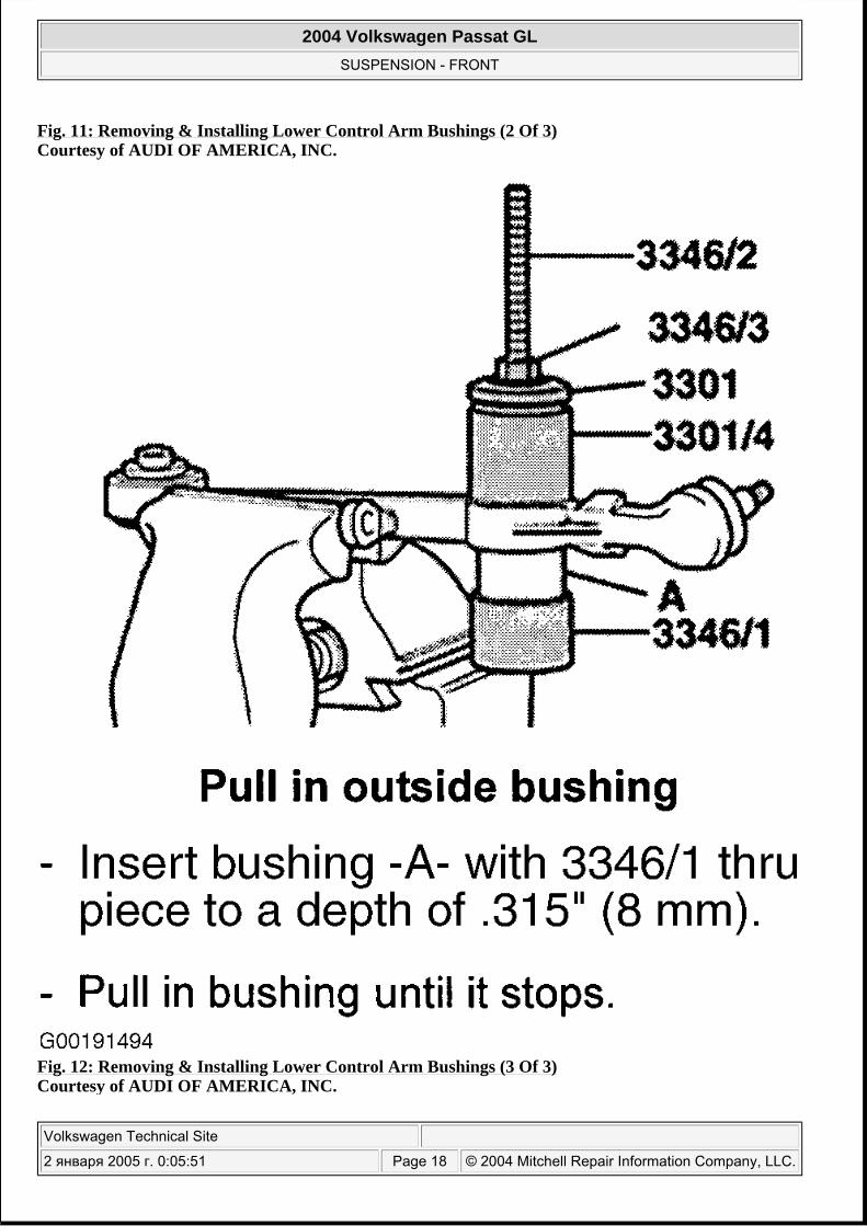
Fig. 11: Removing & Installing Lower Control Arm Bushings (2 Of 3) Courtesy of AUDI OF AMERICA, INC.
Fig. 12: Removing & Installing Lower Control Arm Bushings (3 Of 3) Courtesy of AUDI OF AMERICA, INC.
2004 Volkswagen Passat GL
SUSPENSION - FRONT
Volkswagen Technical Site
2 января 2005 г. 0:05:51 Page 18 © 2004 Mitchell Repair Information Company, LLC.
MOUNTING BRACKET
Removal
1. Raise and support vehicle. Remove wheels. 2.
Remove and discard clip (1) with a pair of pliers. See Fig. 13 . Remove nut (2). Take out hex bolt and pull both control arms out upward. If the hex bolt cannot be removed from the wheel bearing housing, then the hex bolt and the control arms must be pressed out of the wheel bearing housing. See SEPARATING CONNECTIONS BETWEEN UPPER CONTROL ARMS & WHEEL BEARING HOUSING .
CAUTION: The slits in the wheel bearing housing must NOT be widened using a chisel or similar tool.
2004 Volkswagen Passat GL
SUSPENSION - FRONT
Volkswagen Technical Site
2 января 2005 г. 0:05:51 Page 19 © 2004 Mitchell Repair Information Company, LLC.
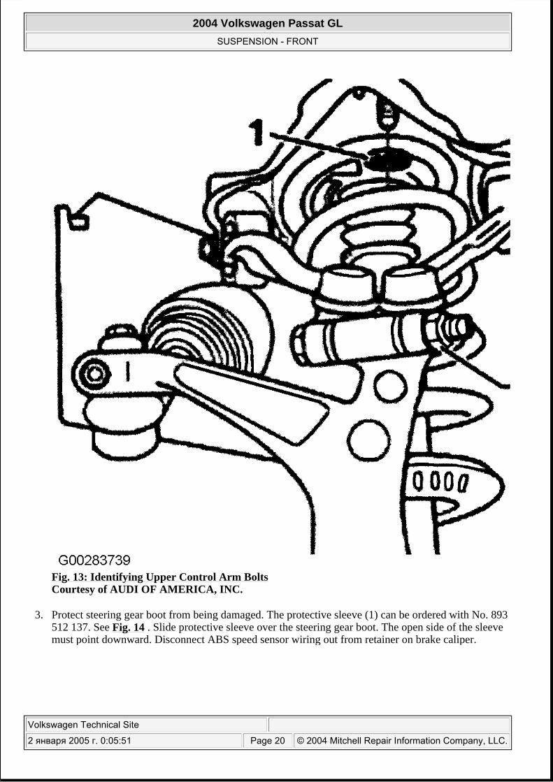
Fig. 13: Identifying Upper Control Arm Bolts Courtesy of AUDI OF AMERICA, INC.
3. Protect steering gear boot from being damaged. The protective sleeve (1) can be ordered with No. 893 512 137. See Fig. 14 . Slide protective sleeve over the steering gear boot. The open side of the sleeve must point downward. Disconnect ABS speed sensor wiring out from retainer on brake caliper.
2004 Volkswagen Passat GL
SUSPENSION - FRONT
Volkswagen Technical Site
2 января 2005 г. 0:05:51 Page 20 © 2004 Mitchell Repair Information Company, LLC.
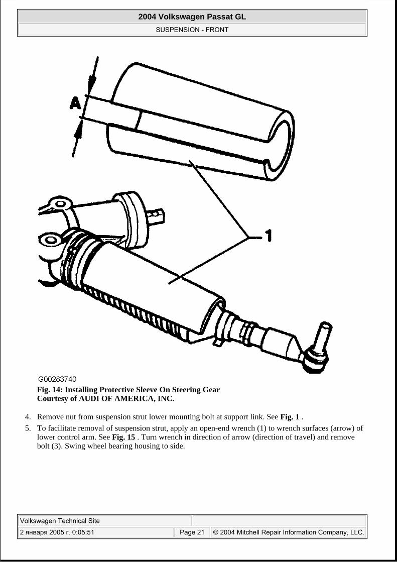
Fig. 14: Installing Protective Sleeve On Steering Gear Courtesy of AUDI OF AMERICA, INC.
4. Remove nut from suspension strut lower mounting bolt at support link. See Fig. 1 . 5. To facilitate removal of suspension strut, apply an open-end wrench (1) to wrench surfaces (arrow) of
lower control arm. See Fig. 15 . Turn wrench in direction of arrow (direction of travel) and remove bolt (3). Swing wheel bearing housing to side.
2004 Volkswagen Passat GL
SUSPENSION - FRONT
Volkswagen Technical Site
2 января 2005 г. 0:05:51 Page 21 © 2004 Mitchell Repair Information Company, LLC.
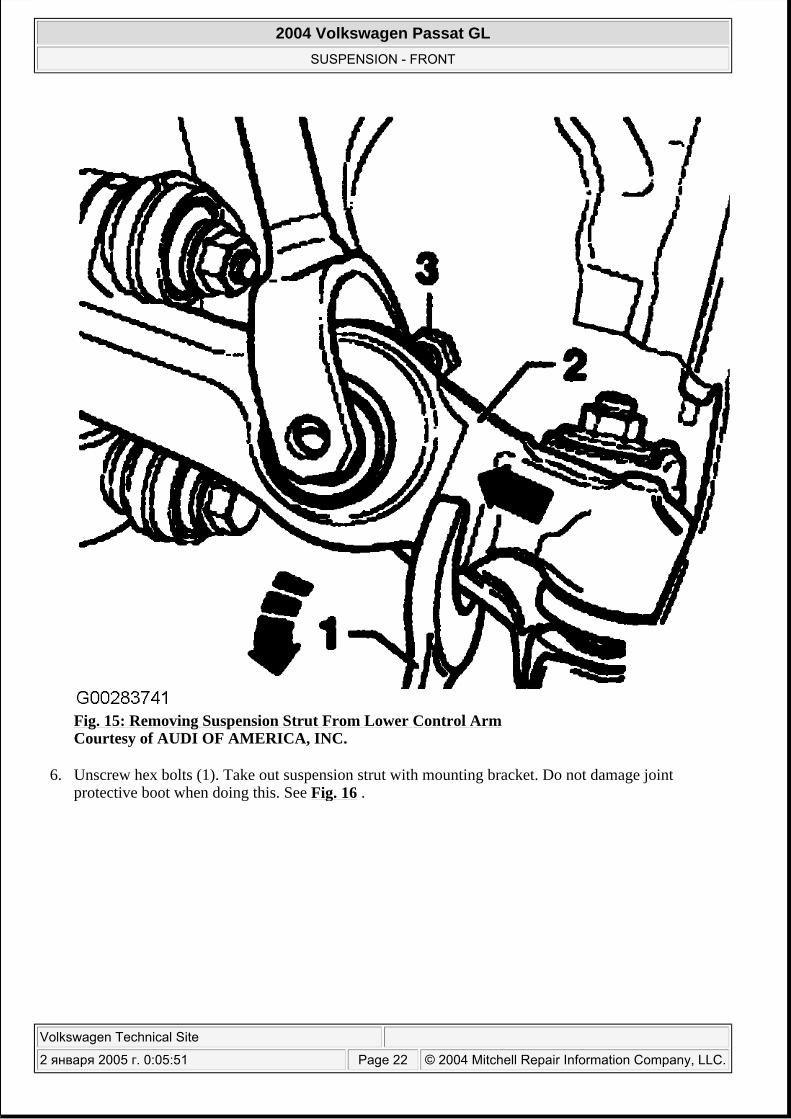
Fig. 15: Removing Suspension Strut From Lower Control Arm Courtesy of AUDI OF AMERICA, INC.
6. Unscrew hex bolts (1). Take out suspension strut with mounting bracket. Do not damage joint protective boot when doing this. See Fig. 16 .
2004 Volkswagen Passat GL
SUSPENSION - FRONT
Volkswagen Technical Site
2 января 2005 г. 0:05:51 Page 22 © 2004 Mitchell Repair Information Company, LLC.
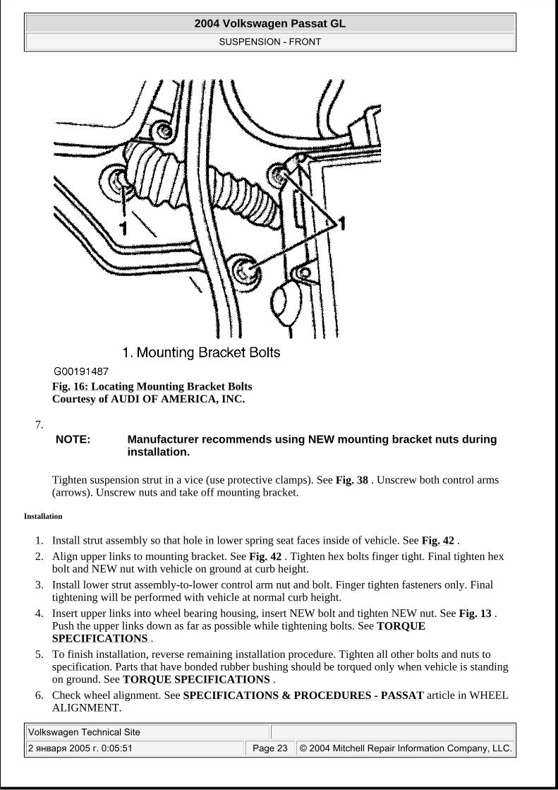
Fig. 16: Locating Mounting Bracket Bolts Courtesy of AUDI OF AMERICA, INC.
7.
Tighten suspension strut in a vice (use protective clamps). See Fig. 38 . Unscrew both control arms (arrows). Unscrew nuts and take off mounting bracket.
Installation
1. Install strut assembly so that hole in lower spring seat faces inside of vehicle. See Fig. 42 . 2. Align upper links to mounting bracket. See Fig. 42 . Tighten hex bolts finger tight. Final tighten hex
bolt and NEW nut with vehicle on ground at curb height. 3. Install lower strut assembly-to-lower control arm nut and bolt. Finger tighten fasteners only. Final
tightening will be performed with vehicle at normal curb height. 4. Insert upper links into wheel bearing housing, insert NEW bolt and tighten NEW nut. See Fig. 13 .
Push the upper links down as far as possible while tightening bolts. See TORQUE SPECIFICATIONS .
5. To finish installation, reverse remaining installation procedure. Tighten all other bolts and nuts to specification. Parts that have bonded rubber bushing should be torqued only when vehicle is standing on ground. See TORQUE SPECIFICATIONS .
6. Check wheel alignment. See SPECIFICATIONS & PROCEDURES - PASSAT article in WHEEL ALIGNMENT.
NOTE: Manufacturer recommends using NEW mounting bracket nuts during installation.
2004 Volkswagen Passat GL
SUSPENSION - FRONT
Volkswagen Technical Site
2 января 2005 г. 0:05:51 Page 23 © 2004 Mitchell Repair Information Company, LLC.
SEPARATING CONNECTIONS BETWEEN UPPER CONTROL ARMS & WHEEL BEARING HOUSING
1. Raise and support vehicle. Remove wheel. 2. Disconnect ABS speed sensor wiring from retainer on brake caliper. Remove nut from upper control
arm retaining bolt in wheel bearing housing (1). See Fig. 17 . Do not loosen other bolts in upper portion of wheel bearing housing.
NOTE: This procedure is only necessary if the hex bolt for the connections between the upper control arms and the wheel bearing housing cannot be removed.
CAUTION: The slits in the wheel bearing housing must NOT be widened using a chisel or similar tool.
2004 Volkswagen Passat GL
SUSPENSION - FRONT
Volkswagen Technical Site
2 января 2005 г. 0:05:51 Page 24 © 2004 Mitchell Repair Information Company, LLC.
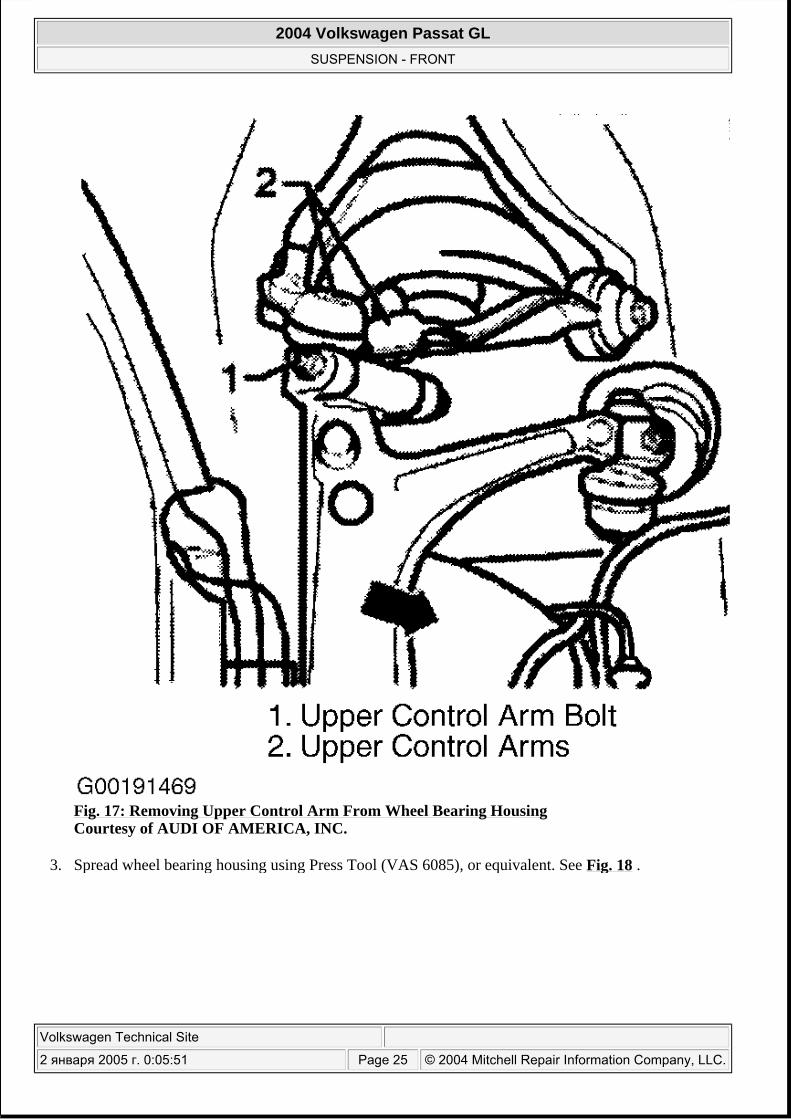
Fig. 17: Removing Upper Control Arm From Wheel Bearing Housing Courtesy of AUDI OF AMERICA, INC.
3. Spread wheel bearing housing using Press Tool (VAS 6085), or equivalent. See Fig. 18 .
2004 Volkswagen Passat GL
SUSPENSION - FRONT
Volkswagen Technical Site
2 января 2005 г. 0:05:51 Page 25 © 2004 Mitchell Repair Information Company, LLC.
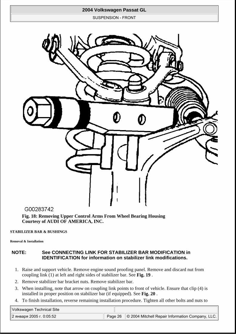
Fig. 18: Removing Upper Control Arms From Wheel Bearing Housing Courtesy of AUDI OF AMERICA, INC.
STABILIZER BAR & BUSHINGS
Removal & Installation
1. Raise and support vehicle. Remove engine sound proofing panel. Remove and discard nut from coupling link (1) at left and right sides of stabilizer bar. See Fig. 19 .
2. Remove stabilizer bar bracket nuts. Remove stabilizer bar. 3. When installing, note that arrow on coupling link points to front of vehicle. Ensure that clip (4) is
installed in proper position on stabilizer bar (if equipped). See Fig. 20 . 4. To finish installation, reverse remaining installation procedure. Tighten all other bolts and nuts to
NOTE: See CONNECTING LINK FOR STABILIZER BAR MODIFICATION in IDENTIFICATION for information on stabilizer link modifications.
2004 Volkswagen Passat GL
SUSPENSION - FRONT
Volkswagen Technical Site
2 января 2005 г. 0:05:52 Page 26 © 2004 Mitchell Repair Information Company, LLC.
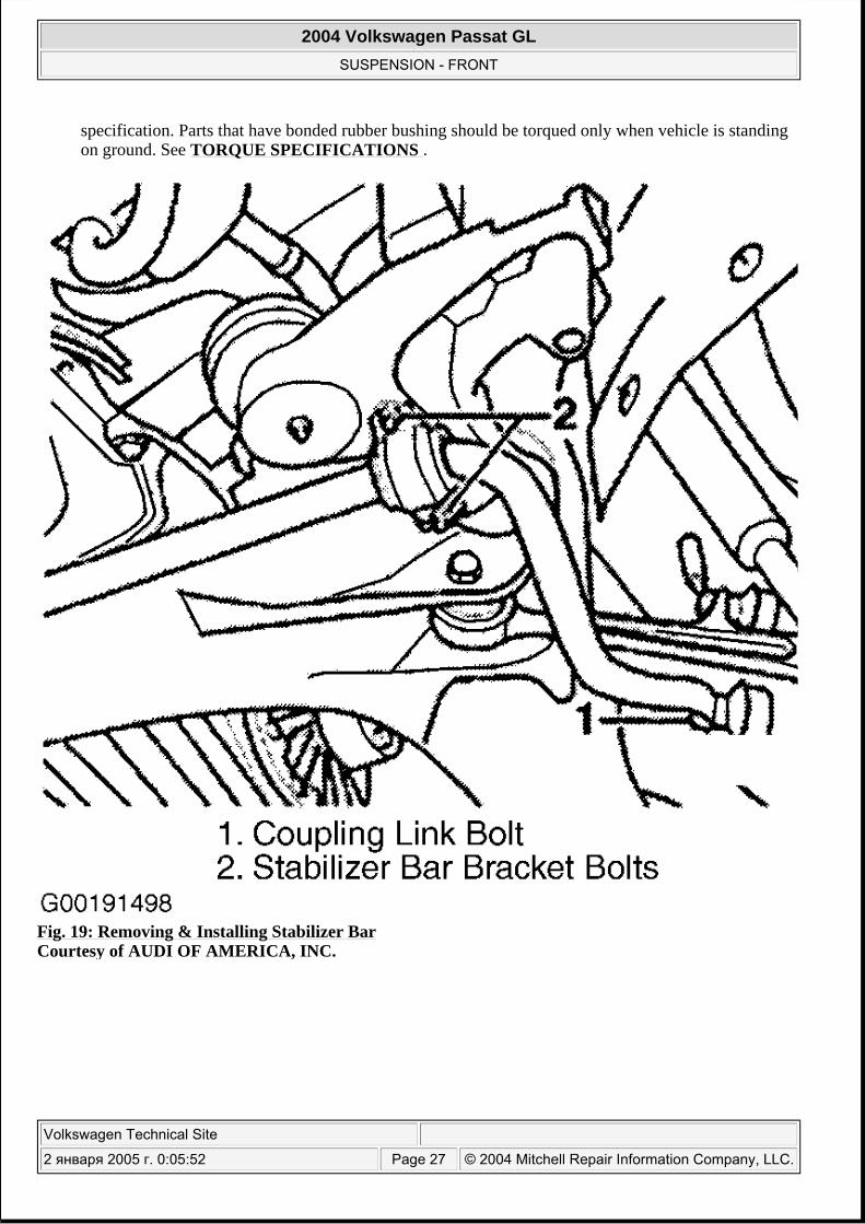
specification. Parts that have bonded rubber bushing should be torqued only when vehicle is standing on ground. See TORQUE SPECIFICATIONS .
Fig. 19: Removing & Installing Stabilizer Bar Courtesy of AUDI OF AMERICA, INC.
2004 Volkswagen Passat GL
SUSPENSION - FRONT
Volkswagen Technical Site
2 января 2005 г. 0:05:52 Page 27 © 2004 Mitchell Repair Information Company, LLC.
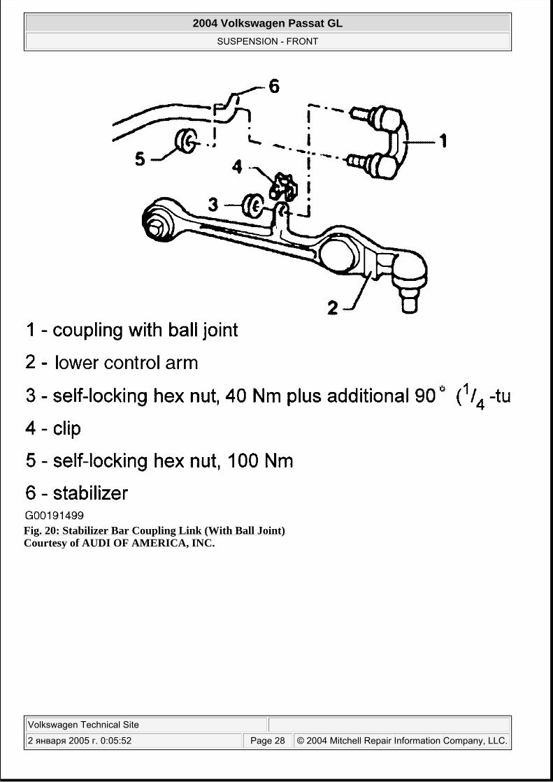
Fig. 20: Stabilizer Bar Coupling Link (With Ball Joint) Courtesy of AUDI OF AMERICA, INC.
2004 Volkswagen Passat GL
SUSPENSION - FRONT
Volkswagen Technical Site
2 января 2005 г. 0:05:52 Page 28 © 2004 Mitchell Repair Information Company, LLC.
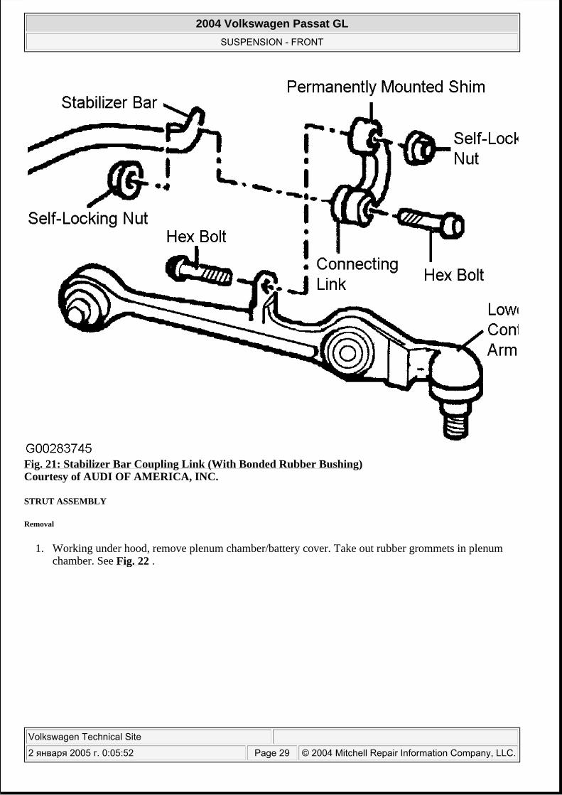
Fig. 21: Stabilizer Bar Coupling Link (With Bonded Rubber Bushing) Courtesy of AUDI OF AMERICA, INC.
STRUT ASSEMBLY
Removal
1. Working under hood, remove plenum chamber/battery cover. Take out rubber grommets in plenum chamber. See Fig. 22 .
2004 Volkswagen Passat GL
SUSPENSION - FRONT
Volkswagen Technical Site
2 января 2005 г. 0:05:52 Page 29 © 2004 Mitchell Repair Information Company, LLC.
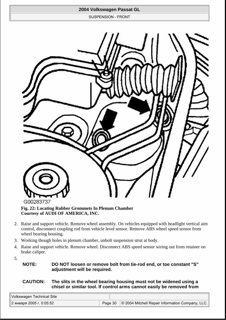
Fig. 22: Locating Rubber Grommets In Plenum Chamber Courtesy of AUDI OF AMERICA, INC.
2. Raise and support vehicle. Remove wheel assembly. On vehicles equipped with headlight vertical aim control, disconnect coupling rod from vehicle level sensor. Remove ABS wheel speed sensor from wheel bearing housing.
3. Working though holes in plenum chamber, unbolt suspension strut at body. 4. Raise and support vehicle. Remove wheel. Disconnect ABS speed sensor wiring out from retainer on
brake caliper. 5.
NOTE: DO NOT loosen or remove bolt from tie-rod end, or toe constant "S" adjustment will be required.
CAUTION: The slits in the wheel bearing housing must not be widened using a chisel or similar tool. If control arms cannot easily be removed from
2004 Volkswagen Passat GL
SUSPENSION - FRONT
Volkswagen Technical Site
2 января 2005 г. 0:05:52 Page 30 © 2004 Mitchell Repair Information Company, LLC.
Remove upper control arm-to-wheel bearing housing nut. See Fig. 17 . Remove hex bolt and lift out control arm. Swing wheel bearing housing towards rear of vehicle.
6. Remove and discard lower strut assembly-to-lower control arm nut and bolt. To facilitate removal of strut, apply an open-jaw wrench to wrench surfaces of lower control arm. Pull wrench towards front of vehicle and remove bolt. See Fig. 15 . Being careful not to damage CV boot, remove strut assembly from vehicle.
7.
Spring Replacement Precautions
Surface of the spring must not be damaged Observe spring color coding The coil spring allocation for vehicles from vehicle identification No. 3B-WE 113 562 is performed suspension identification numbers. See IDENTIFYING VEHICLE SUSPENSION under IDENTIFICATION.
Disassembly & Reassembly
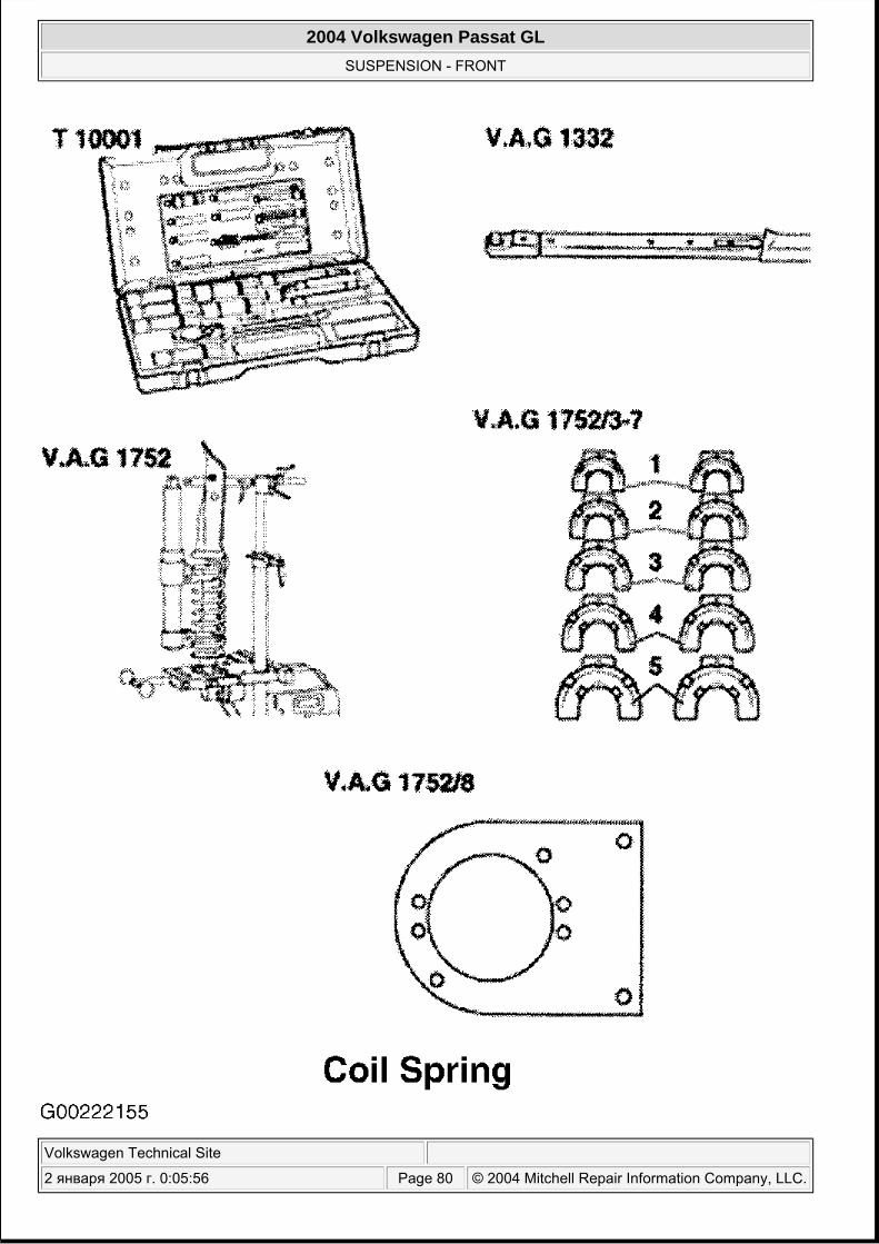
1. Clamp Suspension Strut Mount (VAG 1752/2) into vise. Clamp suspension strut into suspension strut mount at clevis.
2. Compress coil spring with Spring Compressor (VAG 1752/1) and appropriate adapters until upper spring plate is free. Remove piston rod nut. Counter-hold piston rod as necessary. See Fig. 26 .
3. Slowly release tension on spring and remove upper strut mount, mounting bracket and coil spring. Remove bump stop, protective cap, lower spring support. See Fig. 24 . Mark installation position of lower spring plate in relation to strut. Use a plastic hammer to loosen and remove lower spring plate.
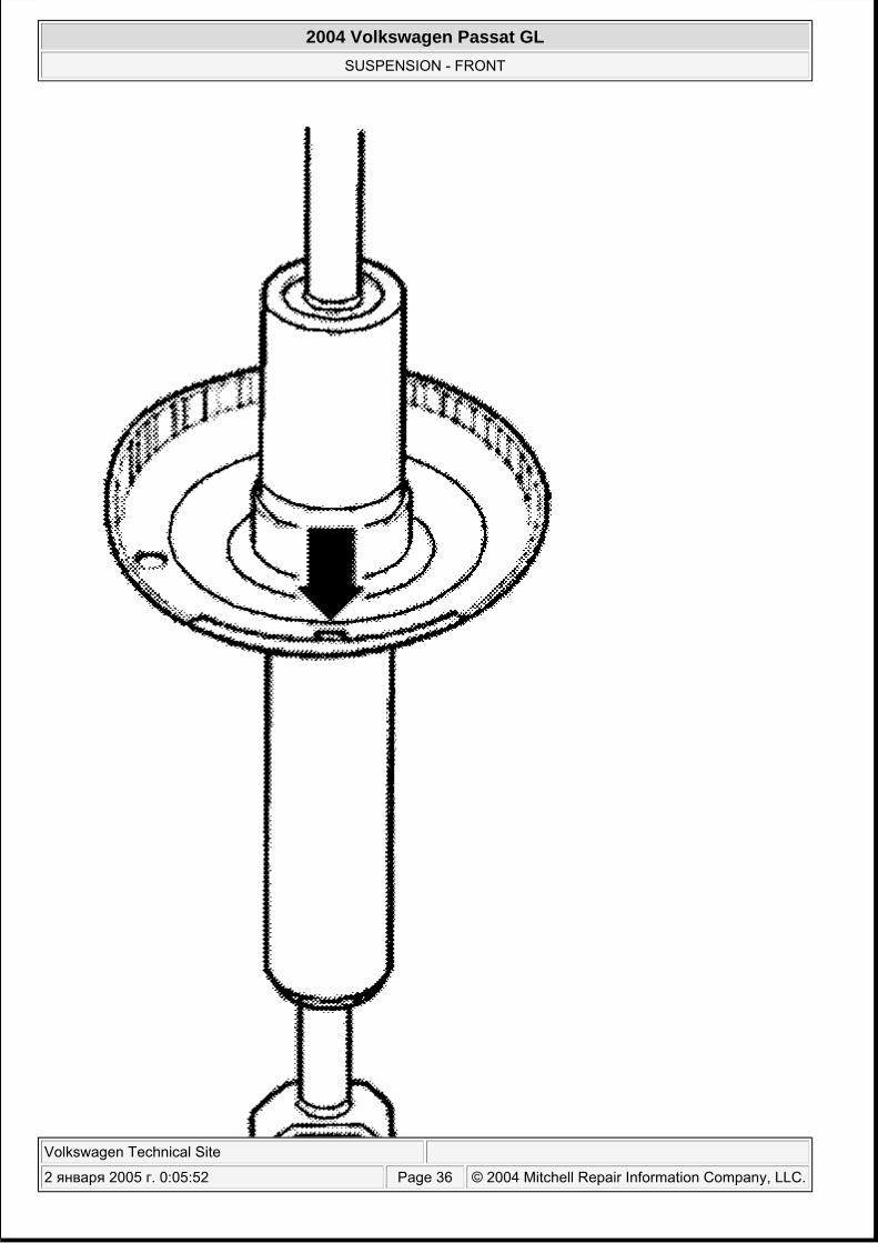
4. Install lower spring plate. Ensure spring plate is aligned correctly. See Fig. 25 . 5. Install lower spring support, protective cap, bump stop, protective sleeve and coil spring. Verify that
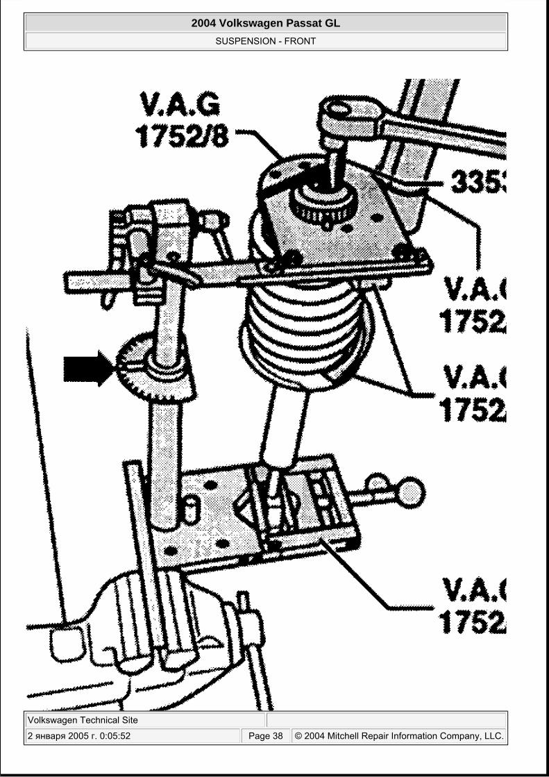
coil spring rests against stop. 6. Set angle scale (arrow) of spring mounting tool V.A.G 1752/2 to 0 degrees. See Fig. 26 . 7. Install upper spring plate, washer and suspension strut mount. Adjust angle scale of Clamping Device
(1752/2) to zero. Bring upper spring seat into 11° position using Adjusting Gauge (1752/8). See Fig. 26 . On adjusting gauge, the 11° setting has "left front" or "right front" markings, ensure that left and right side 11° positions of spring plate (seat) are symmetrical. See Fig. 27 .
8. Top end of coil spring must rest against stop of upper spring plate. See Fig. 23 .
wheel bearing housing, see SEPARATING CONNECTIONS BETWEEN UPPER CONTROL ARMS & WHEEL BEARING HOUSING .
2004 Volkswagen Passat GL
SUSPENSION - FRONT
Volkswagen Technical Site
2 января 2005 г. 0:05:52 Page 31 © 2004 Mitchell Repair Information Company, LLC.
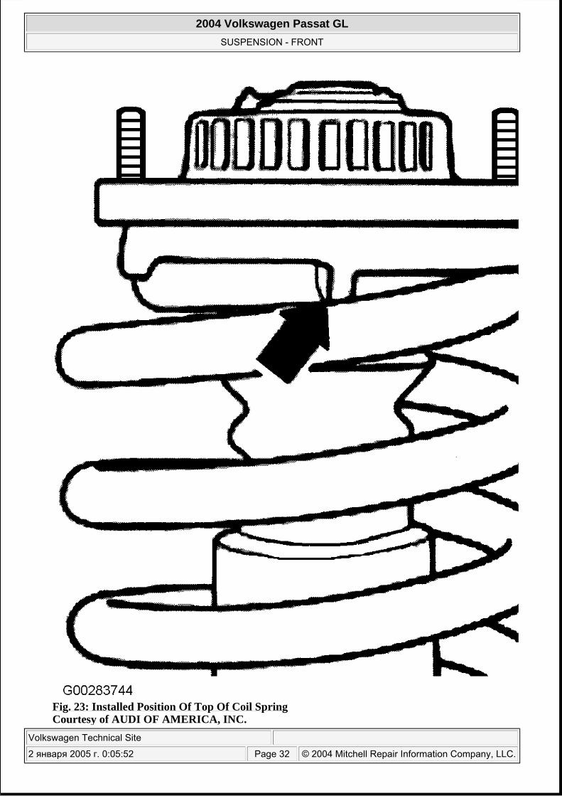
Fig. 23: Installed Position Of Top Of Coil Spring Courtesy of AUDI OF AMERICA, INC.
2004 Volkswagen Passat GL
SUSPENSION - FRONT
Volkswagen Technical Site
2 января 2005 г. 0:05:52 Page 32 © 2004 Mitchell Repair Information Company, LLC.
9. Tighten piston rod nut to specification. See TORQUE SPECIFICATIONS . Remove strut assembly from strut mount.
2004 Volkswagen Passat GL
SUSPENSION - FRONT
Volkswagen Technical Site
2 января 2005 г. 0:05:52 Page 33 © 2004 Mitchell Repair Information Company, LLC.
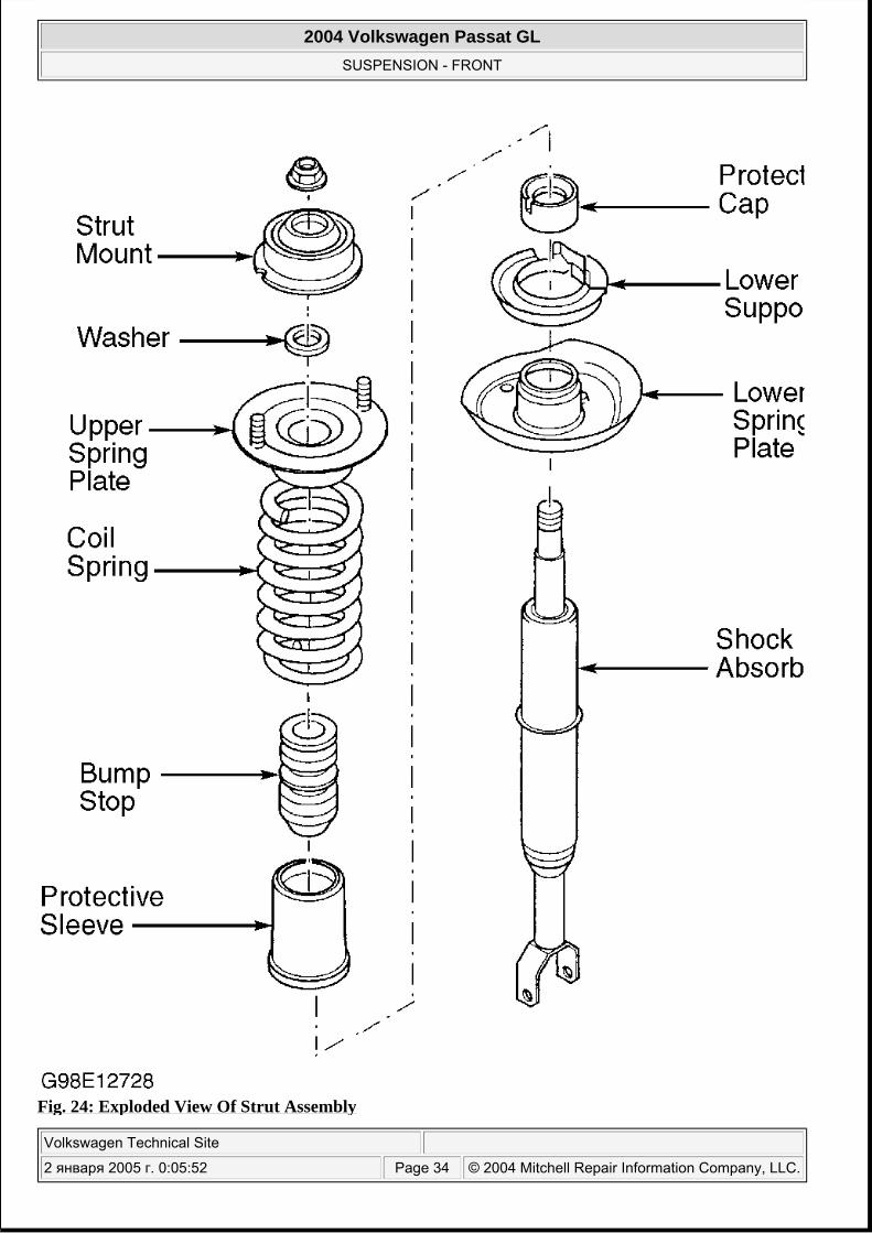
Fig. 24: Exploded View Of Strut Assembly
2004 Volkswagen Passat GL
SUSPENSION - FRONT
Volkswagen Technical Site
2 января 2005 г. 0:05:52 Page 34 © 2004 Mitchell Repair Information Company, LLC.
Courtesy of VOLKSWAGEN UNITED STATES, INC.
2004 Volkswagen Passat GL
SUSPENSION - FRONT
Volkswagen Technical Site
2 января 2005 г. 0:05:52 Page 35 © 2004 Mitchell Repair Information Company, LLC.
2004 Volkswagen Passat GL
SUSPENSION - FRONT
Volkswagen Technical Site
2 января 2005 г. 0:05:52 Page 36 © 2004 Mitchell Repair Information Company, LLC.

Fig. 25: Checking Lower Spring Plate Installation Position Courtesy of AUDI OF AMERICA, INC.
2004 Volkswagen Passat GL
SUSPENSION - FRONT
Volkswagen Technical Site
2 января 2005 г. 0:05:52 Page 37 © 2004 Mitchell Repair Information Company, LLC.
2004 Volkswagen Passat GL
SUSPENSION - FRONT
Volkswagen Technical Site
2 января 2005 г. 0:05:52 Page 38 © 2004 Mitchell Repair Information Company, LLC.
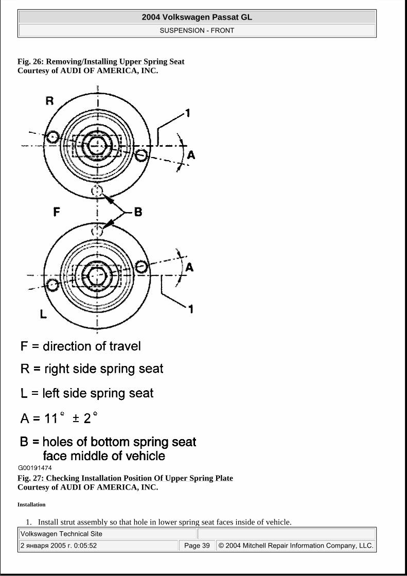
Fig. 26: Removing/Installing Upper Spring Seat Courtesy of AUDI OF AMERICA, INC.
Fig. 27: Checking Installation Position Of Upper Spring Plate Courtesy of AUDI OF AMERICA, INC.
Installation
1. Install strut assembly so that hole in lower spring seat faces inside of vehicle.
2004 Volkswagen Passat GL
SUSPENSION - FRONT
Volkswagen Technical Site
2 января 2005 г. 0:05:52 Page 39 © 2004 Mitchell Repair Information Company, LLC.
2. Install lower strut assembly-to-lower control arm bolt. Install a NEW nut. Finger tighten fasteners only
3. Install upper control arms into wheel bearing housing. Install bolt with NEW nut. Push upper control arms down as far as possible while tightening bolt. Tighten bolt to specification. See TORQUE SPECIFICATIONS .
4. To finish installation, reverse remaining installation procedure. Tighten all other bolts and nuts to specification. Parts that have bonded rubber bushing should be torqued only when vehicle is standing on ground. See TORQUE SPECIFICATIONS .
Check wheel alignment. See SPECIFICATIONS & PROCEDURES - PASSAT article in WHEEL ALIGNMENT.
STRUT CARTRIDGE
Removal & Installation
Remove strut assembly and disassemble. See STRUT ASSEMBLY .
SUBFRAME & SUBFRAME BUSHINGS
Removal
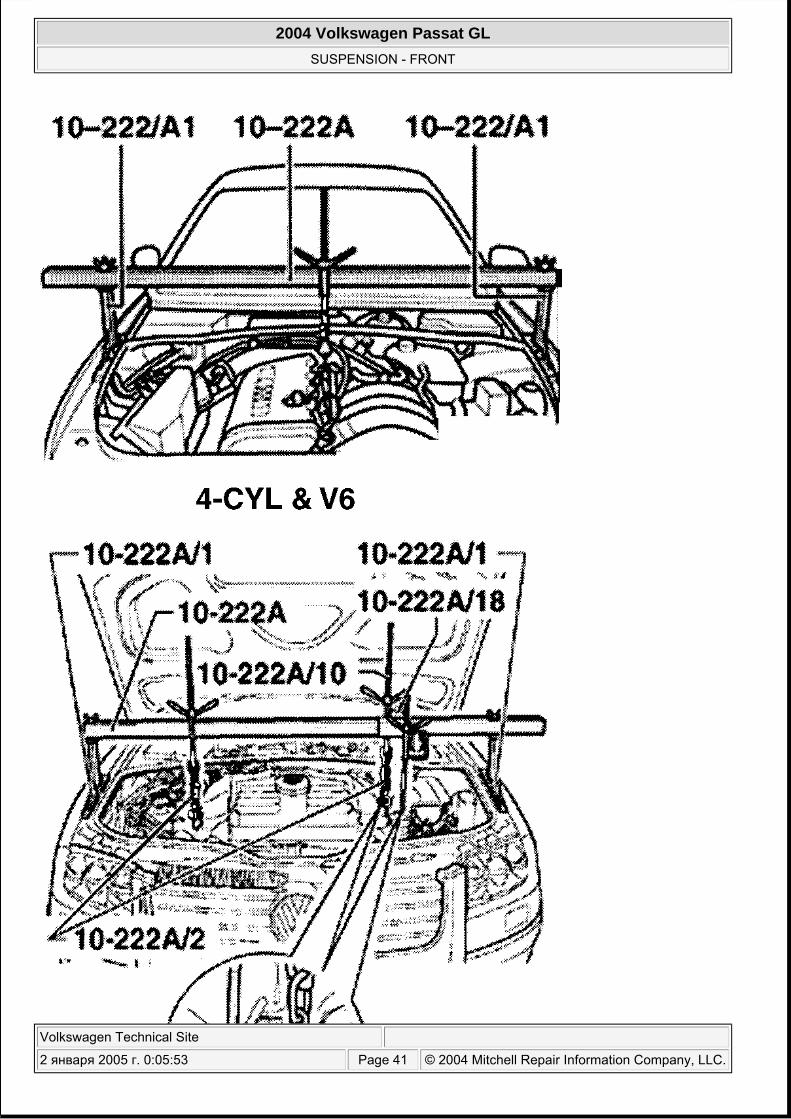
1. Install Support Bar (10-222A) along with appropriate support to engine. See Fig. 28 . On vehicles equipped with V8, remove oil filler pipe from engine. Take weight of engine/transmission assembly off the spindles.
2. Raise and support vehicle. Remove wheels. Remove sound insulation tray. On vehicles equipped with self-leveling headlights, unclip coupling rod from lower control arm. See Fig. 3 .
3. Before loosing subframe, verify subframe alignment with Alignment Tool (3393). See Fig. 29 . If this is not the case, perform axle alignment measurements after installing the subframe.
4. Remove lower strut mount bolts. Remove stabilizer bar coupling links. Remove lower control arm-to-subframe nut and bolt. Remove guide control arm-to-subframe nut and bolt. Remove transmission mount bolts (1). See Fig. 30 .
5.
On vehicles with all-wheel drive, placing mating marks on driveshaft flange and transmission mating flange. Remove self-locking bolts. Separate driveshaft from transmission.
6. Place transmission jack with a wood block under subframe and lift subframe slightly. Unscrew bolts (1) and (2) at rear of subframe. See Fig. 31 . Lower subframe slightly.
7. Remove and discard hex bolts and nuts for track control arm and guide control arm arm. Clear ABS vehicle speed sensor wiring. Pull both track control arm and guide control arm arms out of subframe.
8. Remove subframe bolts "A" and "B". See Fig. 32 . Remove subframe.
NOTE: See SUBFRAME BOLT VERSIONS under TORQUE SPECIFICATIONS for information on subframe retaining bolts.
CAUTION: Manufacturer recommends replacing driveshaft flange self-locking bolts.
2004 Volkswagen Passat GL
SUSPENSION - FRONT
Volkswagen Technical Site
2 января 2005 г. 0:05:53 Page 40 © 2004 Mitchell Repair Information Company, LLC.
2004 Volkswagen Passat GL
SUSPENSION - FRONT
Volkswagen Technical Site
2 января 2005 г. 0:05:53 Page 41 © 2004 Mitchell Repair Information Company, LLC.
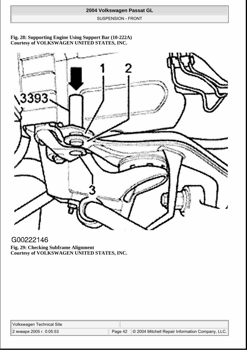
Fig. 28: Supporting Engine Using Support Bar (10-222A) Courtesy of VOLKSWAGEN UNITED STATES, INC.
Fig. 29: Checking Subframe Alignment Courtesy of VOLKSWAGEN UNITED STATES, INC.
2004 Volkswagen Passat GL
SUSPENSION - FRONT
Volkswagen Technical Site
2 января 2005 г. 0:05:53 Page 42 © 2004 Mitchell Repair Information Company, LLC.
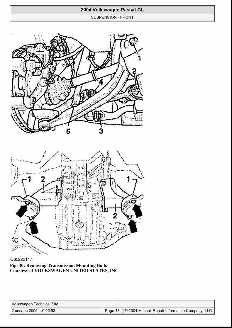
Fig. 30: Removing Transmission Mounting Bolts Courtesy of VOLKSWAGEN UNITED STATES, INC.
2004 Volkswagen Passat GL
SUSPENSION - FRONT
Volkswagen Technical Site
2 января 2005 г. 0:05:53 Page 43 © 2004 Mitchell Repair Information Company, LLC.
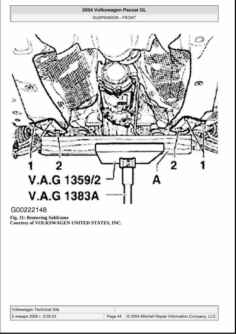
Fig. 31: Removing Subframe Courtesy of VOLKSWAGEN UNITED STATES, INC.
2004 Volkswagen Passat GL
SUSPENSION - FRONT
Volkswagen Technical Site
2 января 2005 г. 0:05:53 Page 44 © 2004 Mitchell Repair Information Company, LLC.
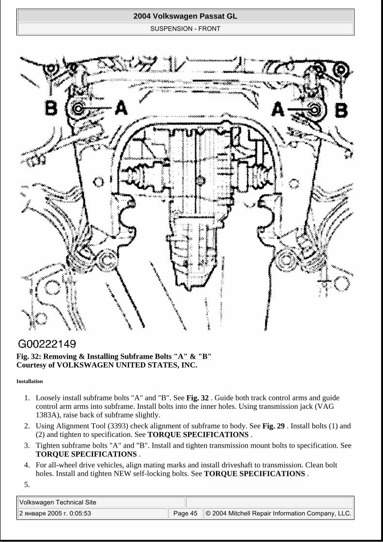
Fig. 32: Removing & Installing Subframe Bolts "A" & "B" Courtesy of VOLKSWAGEN UNITED STATES, INC.
Installation
1. Loosely install subframe bolts "A" and "B". See Fig. 32 . Guide both track control arms and guide control arm arms into subframe. Install bolts into the inner holes. Using transmission jack (VAG 1383A), raise back of subframe slightly.
2. Using Alignment Tool (3393) check alignment of subframe to body. See Fig. 29 . Install bolts (1) and (2) and tighten to specification. See TORQUE SPECIFICATIONS .
3. Tighten subframe bolts "A" and "B". Install and tighten transmission mount bolts to specification. See TORQUE SPECIFICATIONS .
4. For all-wheel drive vehicles, align mating marks and install driveshaft to transmission. Clean bolt holes. Install and tighten NEW self-locking bolts. See TORQUE SPECIFICATIONS .
5.
2004 Volkswagen Passat GL
SUSPENSION - FRONT
Volkswagen Technical Site
2 января 2005 г. 0:05:53 Page 45 © 2004 Mitchell Repair Information Company, LLC.
To finish installation, reverse remaining removal procedure. Tighten all other bolts and nuts to specification. Parts that have bonded rubber bushing (guide control arm and lower control arm) should be final torqued only when vehicle is standing on ground (curb height). See TORQUE SPECIFICATIONS .
6. Check wheel alignment. See SPECIFICATIONS & PROCEDURES - PASSAT article in WHEEL ALIGNMENT.
Subframe Bushings
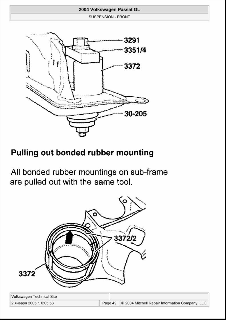
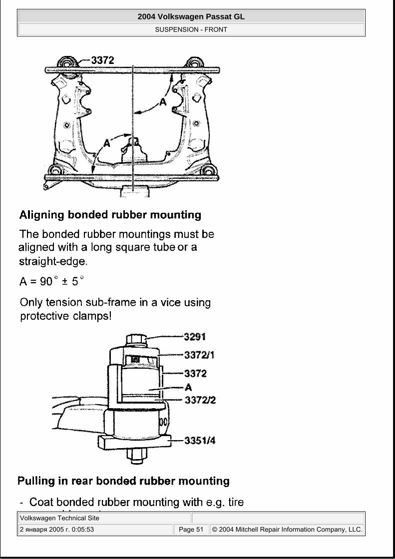
Subframe must be removed from vehicle to replace bushings. Cut or saw off rubber shoulder on bushing, cut rubber up to outer bearing bushing. If rubber shoulder is not removed completely, removal tool cannot seat correctly and will fall off. If painted surface on subframe is damaged, recoat with corrosion protection. Use illustrations to remove and install subframe bushings. See Fig. 33 -Fig. 37 .
NOTE: Manufacturer recommends replacing guide control arm-to-subframe bolt and nut, and lower control arm-to-subframe bolt and nut during installation.
2004 Volkswagen Passat GL
SUSPENSION - FRONT
Volkswagen Technical Site
2 января 2005 г. 0:05:53 Page 46 © 2004 Mitchell Repair Information Company, LLC.

2004 Volkswagen Passat GL
SUSPENSION - FRONT
Volkswagen Technical Site
2 января 2005 г. 0:05:53 Page 47 © 2004 Mitchell Repair Information Company, LLC.
Fig. 33: Removing & Installing Subframe Mounting Bushings (1 Of 5) Courtesy of VOLKSWAGEN UNITED STATES, INC.
2004 Volkswagen Passat GL
SUSPENSION - FRONT
Volkswagen Technical Site
2 января 2005 г. 0:05:53 Page 48 © 2004 Mitchell Repair Information Company, LLC.
2004 Volkswagen Passat GL
SUSPENSION - FRONT
Volkswagen Technical Site
2 января 2005 г. 0:05:53 Page 49 © 2004 Mitchell Repair Information Company, LLC.

Fig. 34: Removing & Installing Subframe Mounting Bushings (2 Of 5) Courtesy of VOLKSWAGEN UNITED STATES, INC.
2004 Volkswagen Passat GL
SUSPENSION - FRONT
Volkswagen Technical Site
2 января 2005 г. 0:05:53 Page 50 © 2004 Mitchell Repair Information Company, LLC.
2004 Volkswagen Passat GL
SUSPENSION - FRONT
Volkswagen Technical Site
2 января 2005 г. 0:05:53 Page 51 © 2004 Mitchell Repair Information Company, LLC.
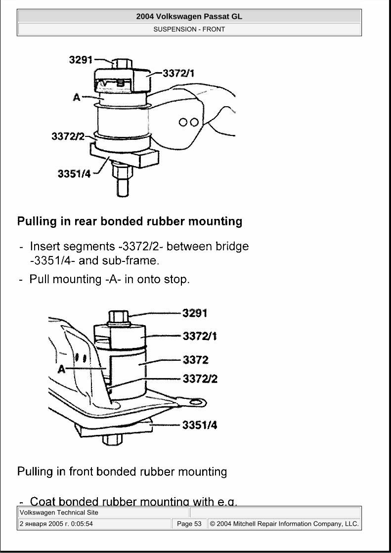
Fig. 35: Removing & Installing Subframe Mounting Bushings (3 Of 5) Courtesy of VOLKSWAGEN UNITED STATES, INC.
2004 Volkswagen Passat GL
SUSPENSION - FRONT
Volkswagen Technical Site
2 января 2005 г. 0:05:54 Page 52 © 2004 Mitchell Repair Information Company, LLC.
2004 Volkswagen Passat GL
SUSPENSION - FRONT
Volkswagen Technical Site
2 января 2005 г. 0:05:54 Page 53 © 2004 Mitchell Repair Information Company, LLC.
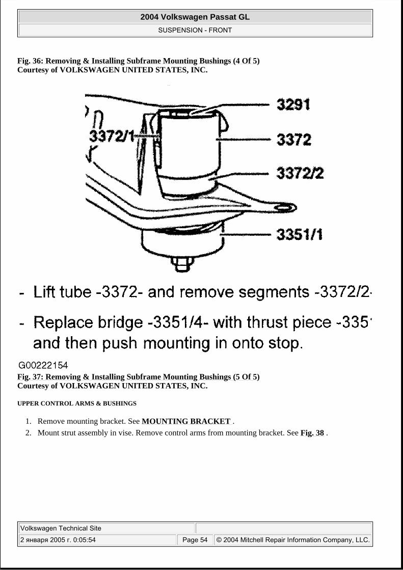
Fig. 36: Removing & Installing Subframe Mounting Bushings (4 Of 5) Courtesy of VOLKSWAGEN UNITED STATES, INC.
Fig. 37: Removing & Installing Subframe Mounting Bushings (5 Of 5) Courtesy of VOLKSWAGEN UNITED STATES, INC.
UPPER CONTROL ARMS & BUSHINGS
1. Remove mounting bracket. See MOUNTING BRACKET . 2. Mount strut assembly in vise. Remove control arms from mounting bracket. See Fig. 38 .
2004 Volkswagen Passat GL
SUSPENSION - FRONT
Volkswagen Technical Site
2 января 2005 г. 0:05:54 Page 54 © 2004 Mitchell Repair Information Company, LLC.
2004 Volkswagen Passat GL
SUSPENSION - FRONT
Volkswagen Technical Site
2 января 2005 г. 0:05:54 Page 55 © 2004 Mitchell Repair Information Company, LLC.
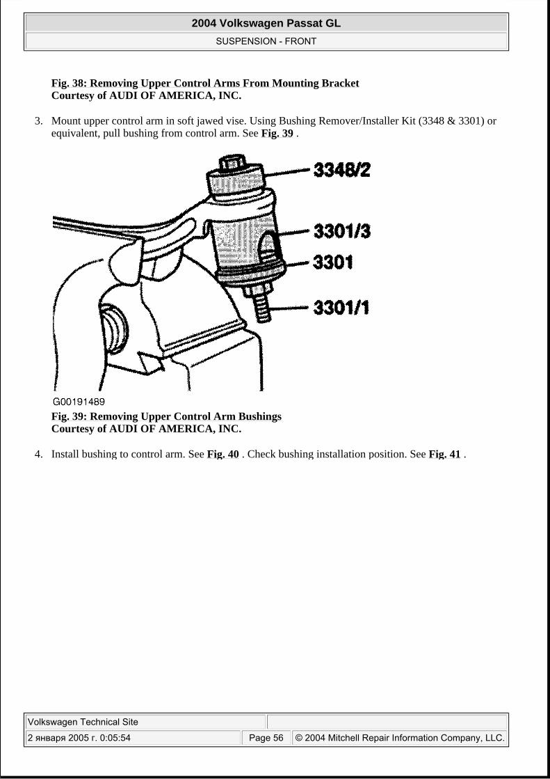
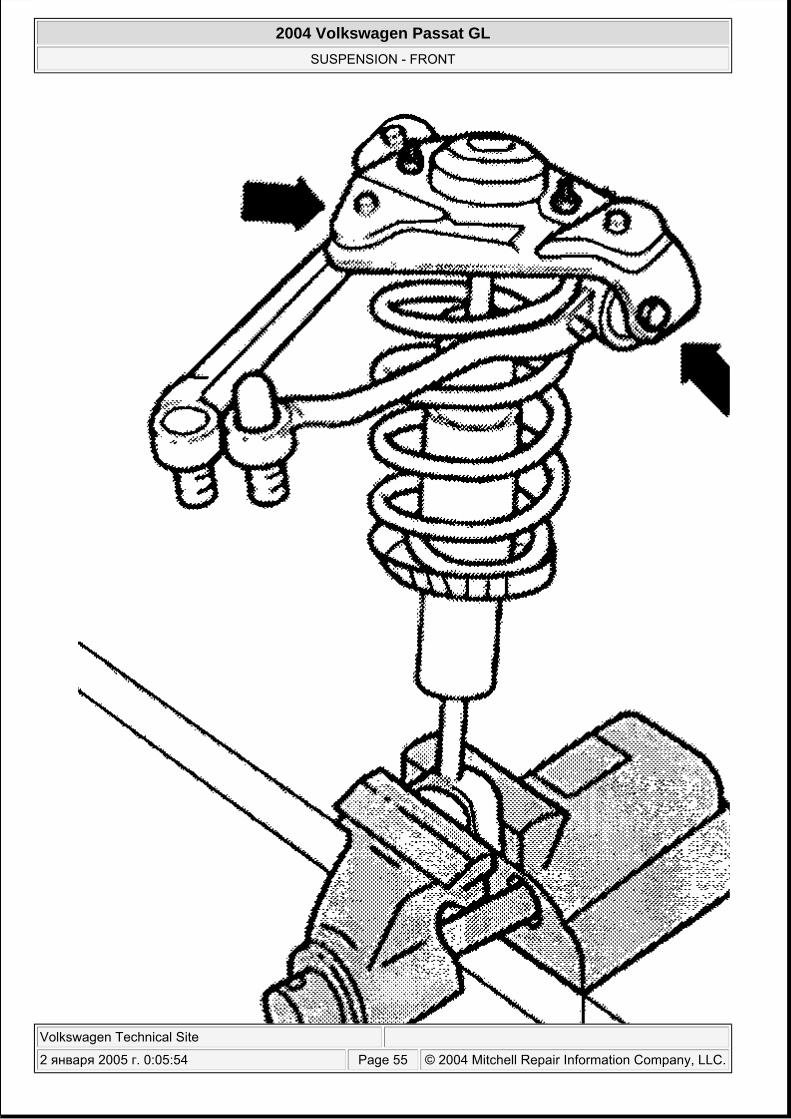
Fig. 38: Removing Upper Control Arms From Mounting Bracket Courtesy of AUDI OF AMERICA, INC.
3. Mount upper control arm in soft jawed vise. Using Bushing Remover/Installer Kit (3348 & 3301) or equivalent, pull bushing from control arm. See Fig. 39 .
Fig. 39: Removing Upper Control Arm Bushings Courtesy of AUDI OF AMERICA, INC.
4. Install bushing to control arm. See Fig. 40 . Check bushing installation position. See Fig. 41 .
2004 Volkswagen Passat GL
SUSPENSION - FRONT
Volkswagen Technical Site
2 января 2005 г. 0:05:54 Page 56 © 2004 Mitchell Repair Information Company, LLC.
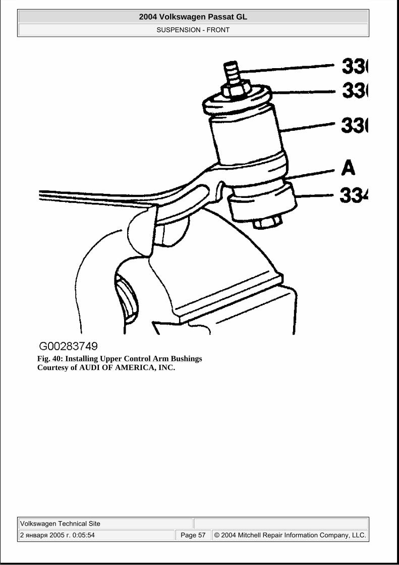
Fig. 40: Installing Upper Control Arm Bushings Courtesy of AUDI OF AMERICA, INC.
2004 Volkswagen Passat GL
SUSPENSION - FRONT
Volkswagen Technical Site
2 января 2005 г. 0:05:54 Page 57 © 2004 Mitchell Repair Information Company, LLC.
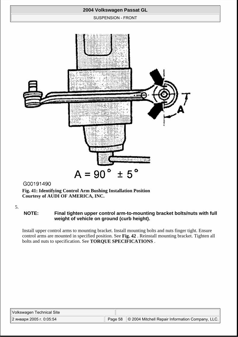
Fig. 41: Identifying Control Arm Bushing Installation Position Courtesy of AUDI OF AMERICA, INC.
5.
Install upper control arms to mounting bracket. Install mounting bolts and nuts finger tight. Ensure control arms are mounted in specified position. See Fig. 42 . Reinstall mounting bracket. Tighten all bolts and nuts to specification. See TORQUE SPECIFICATIONS .
NOTE: Final tighten upper control arm-to-mounting bracket bolts/nuts with full weight of vehicle on ground (curb height).
2004 Volkswagen Passat GL
SUSPENSION - FRONT
Volkswagen Technical Site
2 января 2005 г. 0:05:54 Page 58 © 2004 Mitchell Repair Information Company, LLC.
2004 Volkswagen Passat GL
SUSPENSION - FRONT
Volkswagen Technical Site
2 января 2005 г. 0:05:54 Page 59 © 2004 Mitchell Repair Information Company, LLC.
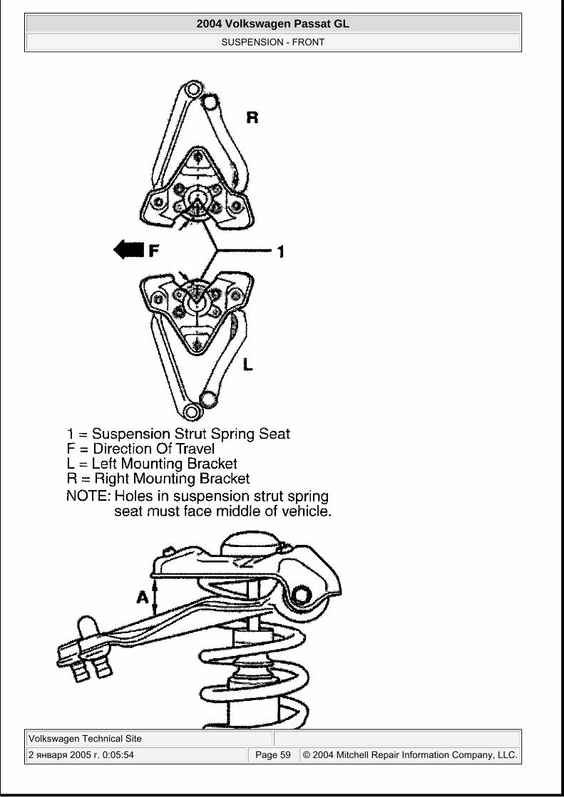
Fig. 42: Installed Position Of Upper Control Arms Courtesy of VOLKSWAGEN UNITED STATES, INC.
WHEEL BEARINGS (WHEEL BEARING HOUSING REMOVED FROM VEHICLE)
Removal & Installation
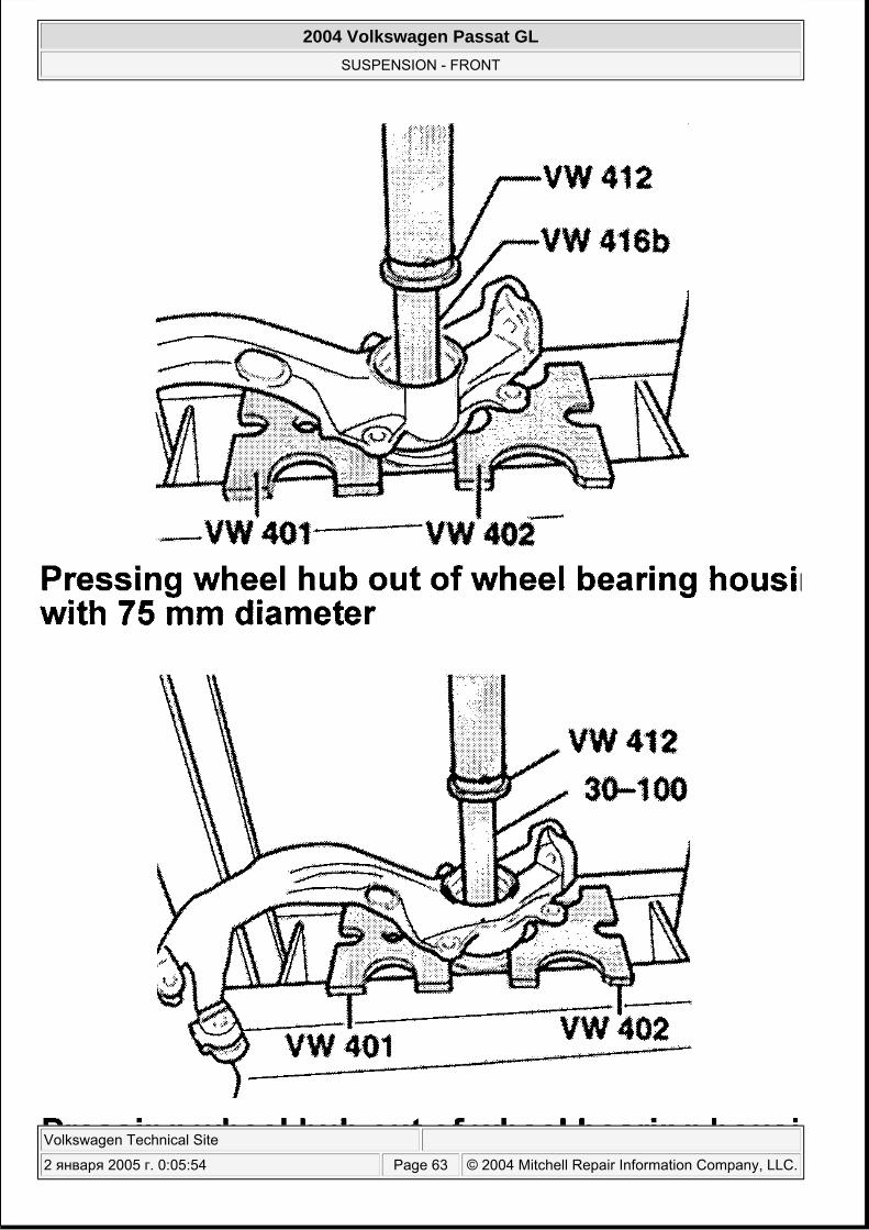
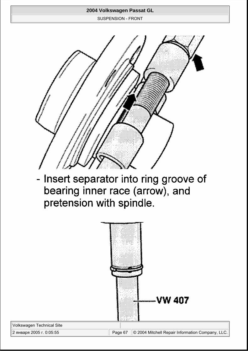
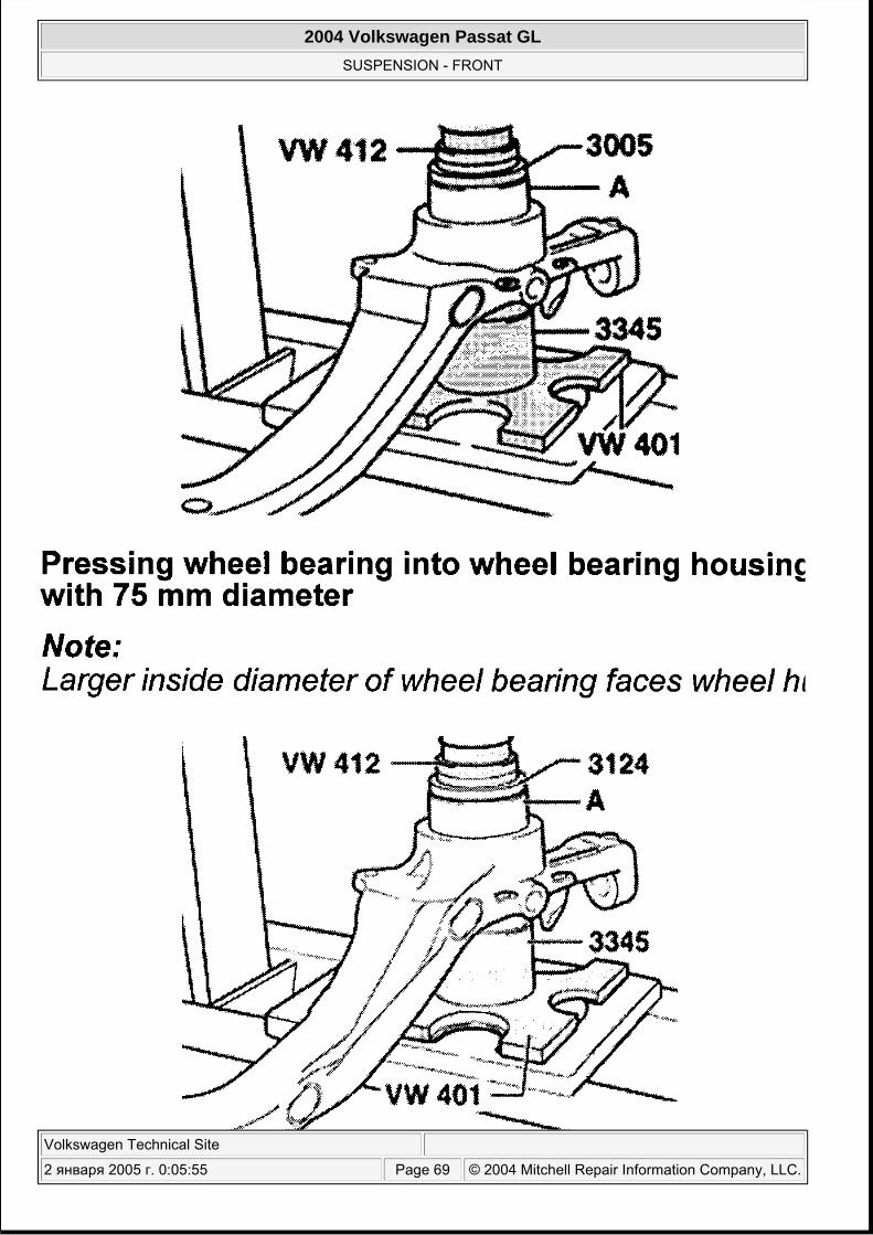
Remove wheel bearing housing. See WHEEL BEARING HOUSING . To replace wheel bearing with wheel bearing housing removed from vehicle, use following illustrations. See Fig. 43 -Fig. 48 .
NOTE: Wheel bearing MUST be replaced if removed, as removal will damage bearing. During any removal and installation procedure, if axle nut/bolt is removed or installed, do so with vehicle resting on floor at full curb weight. Always replace axle shaft self-locking nut/bolt with NEW parts when removed.
2004 Volkswagen Passat GL
SUSPENSION - FRONT
Volkswagen Technical Site
2 января 2005 г. 0:05:54 Page 60 © 2004 Mitchell Repair Information Company, LLC.

Fig. 43: Exploded View Of Hub & Bearing Assembly (Steel Housing)
2004 Volkswagen Passat GL
SUSPENSION - FRONT
Volkswagen Technical Site
2 января 2005 г. 0:05:54 Page 61 © 2004 Mitchell Repair Information Company, LLC.
Courtesy of AUDI OF AMERICA, INC.
2004 Volkswagen Passat GL
SUSPENSION - FRONT
Volkswagen Technical Site
2 января 2005 г. 0:05:54 Page 62 © 2004 Mitchell Repair Information Company, LLC.
2004 Volkswagen Passat GL
SUSPENSION - FRONT
Volkswagen Technical Site
2 января 2005 г. 0:05:54 Page 63 © 2004 Mitchell Repair Information Company, LLC.
Fig. 44: Pressing Wheel Hub From Wheel Bearing Courtesy of AUDI OF AMERICA, INC.
2004 Volkswagen Passat GL
SUSPENSION - FRONT
Volkswagen Technical Site
2 января 2005 г. 0:05:54 Page 64 © 2004 Mitchell Repair Information Company, LLC.
2004 Volkswagen Passat GL
SUSPENSION - FRONT
Volkswagen Technical Site
2 января 2005 г. 0:05:54 Page 65 © 2004 Mitchell Repair Information Company, LLC.
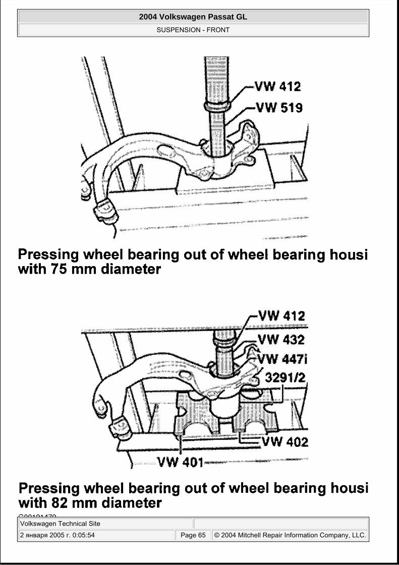
Fig. 45: Pressing Wheel Bearing From Wheel Bearing Housing Courtesy of AUDI OF AMERICA, INC.
2004 Volkswagen Passat GL
SUSPENSION - FRONT
Volkswagen Technical Site
2 января 2005 г. 0:05:55 Page 66 © 2004 Mitchell Repair Information Company, LLC.
2004 Volkswagen Passat GL
SUSPENSION - FRONT
Volkswagen Technical Site
2 января 2005 г. 0:05:55 Page 67 © 2004 Mitchell Repair Information Company, LLC.

Fig. 46: Pressing Wheel Bearing Inner Race From Wheel Hub Courtesy of AUDI OF AMERICA, INC.
2004 Volkswagen Passat GL
SUSPENSION - FRONT
Volkswagen Technical Site
2 января 2005 г. 0:05:55 Page 68 © 2004 Mitchell Repair Information Company, LLC.
2004 Volkswagen Passat GL
SUSPENSION - FRONT
Volkswagen Technical Site
2 января 2005 г. 0:05:55 Page 69 © 2004 Mitchell Repair Information Company, LLC.
Fig. 47: Pressing Wheel Bearing Into Housing Courtesy of AUDI OF AMERICA, INC.
2004 Volkswagen Passat GL
SUSPENSION - FRONT
Volkswagen Technical Site
2 января 2005 г. 0:05:55 Page 70 © 2004 Mitchell Repair Information Company, LLC.
2004 Volkswagen Passat GL
SUSPENSION - FRONT
Volkswagen Technical Site
2 января 2005 г. 0:05:55 Page 71 © 2004 Mitchell Repair Information Company, LLC.
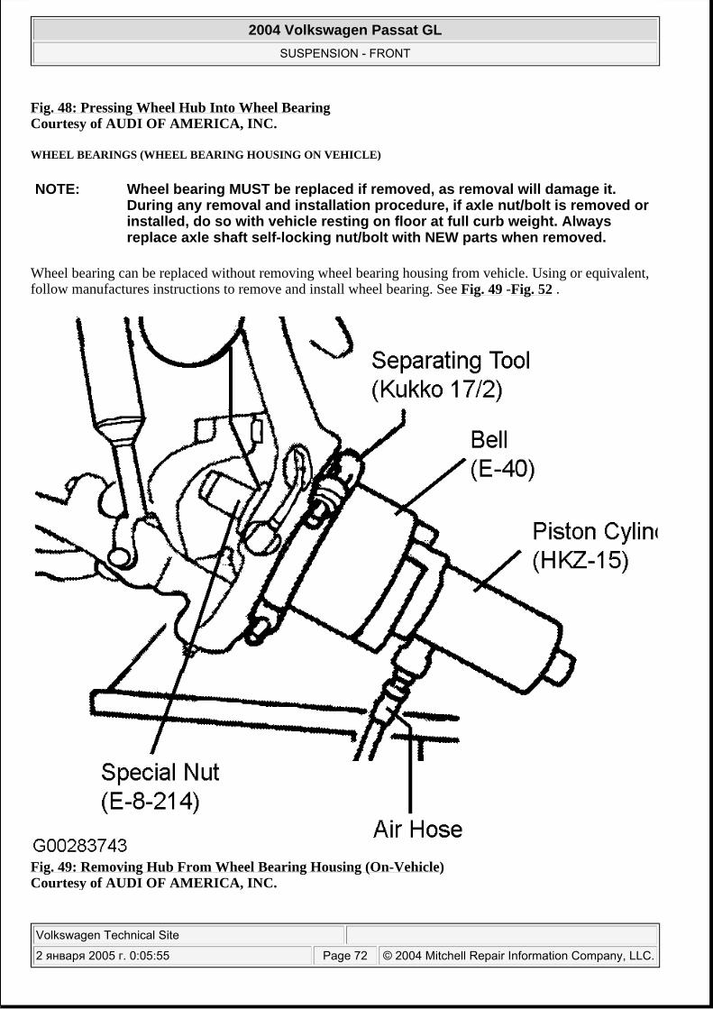
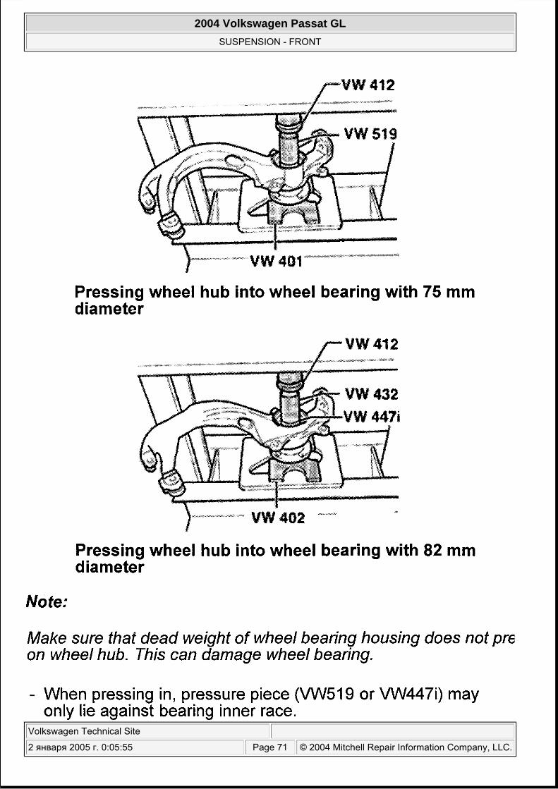
Fig. 48: Pressing Wheel Hub Into Wheel Bearing Courtesy of AUDI OF AMERICA, INC.
WHEEL BEARINGS (WHEEL BEARING HOUSING ON VEHICLE)
Wheel bearing can be replaced without removing wheel bearing housing from vehicle. Using or equivalent, follow manufactures instructions to remove and install wheel bearing. See Fig. 49 -Fig. 52 .
Fig. 49: Removing Hub From Wheel Bearing Housing (On-Vehicle) Courtesy of AUDI OF AMERICA, INC.
NOTE: Wheel bearing MUST be replaced if removed, as removal will damage it. During any removal and installation procedure, if axle nut/bolt is removed or installed, do so with vehicle resting on floor at full curb weight. Always replace axle shaft self-locking nut/bolt with NEW parts when removed.
2004 Volkswagen Passat GL
SUSPENSION - FRONT
Volkswagen Technical Site
2 января 2005 г. 0:05:55 Page 72 © 2004 Mitchell Repair Information Company, LLC.
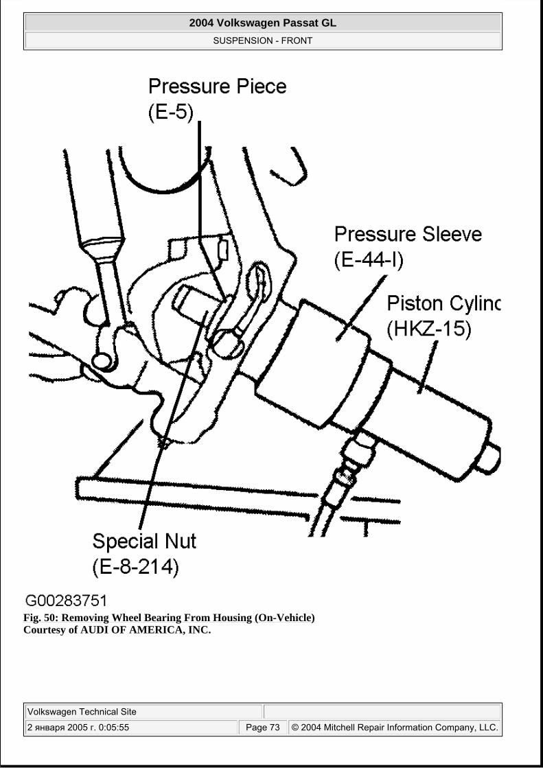
Fig. 50: Removing Wheel Bearing From Housing (On-Vehicle) Courtesy of AUDI OF AMERICA, INC.
2004 Volkswagen Passat GL
SUSPENSION - FRONT
Volkswagen Technical Site
2 января 2005 г. 0:05:55 Page 73 © 2004 Mitchell Repair Information Company, LLC.
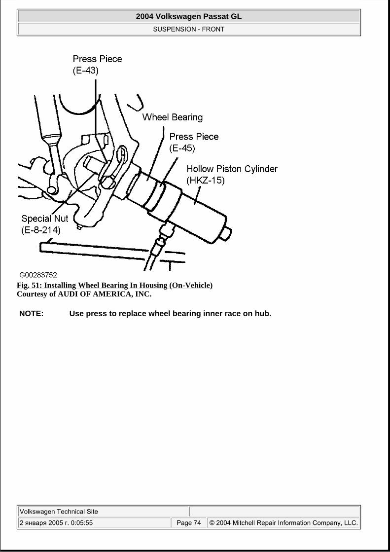
Fig. 51: Installing Wheel Bearing In Housing (On-Vehicle) Courtesy of AUDI OF AMERICA, INC.
NOTE: Use press to replace wheel bearing inner race on hub.
2004 Volkswagen Passat GL
SUSPENSION - FRONT
Volkswagen Technical Site
2 января 2005 г. 0:05:55 Page 74 © 2004 Mitchell Repair Information Company, LLC.
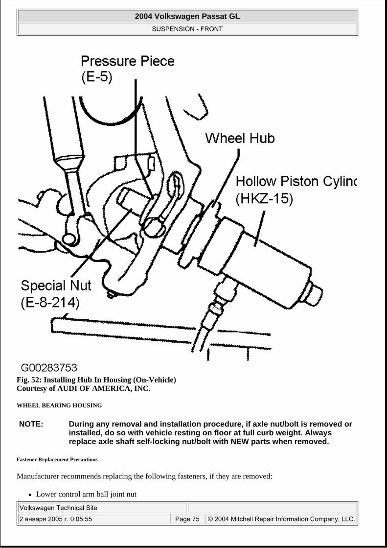
Fig. 52: Installing Hub In Housing (On-Vehicle) Courtesy of AUDI OF AMERICA, INC.
WHEEL BEARING HOUSING
Fastener Replacement Precautions
Manufacturer recommends replacing the following fasteners, if they are removed:
Lower control arm ball joint nut
NOTE: During any removal and installation procedure, if axle nut/bolt is removed or installed, do so with vehicle resting on floor at full curb weight. Always replace axle shaft self-locking nut/bolt with NEW parts when removed.
2004 Volkswagen Passat GL
SUSPENSION - FRONT
Volkswagen Technical Site
2 января 2005 г. 0:05:55 Page 75 © 2004 Mitchell Repair Information Company, LLC.
Guide control arm ball joint nut Tie rod end self-locking nut Upper control arm pinch bolt and nut in wheel bearing housing
Removal
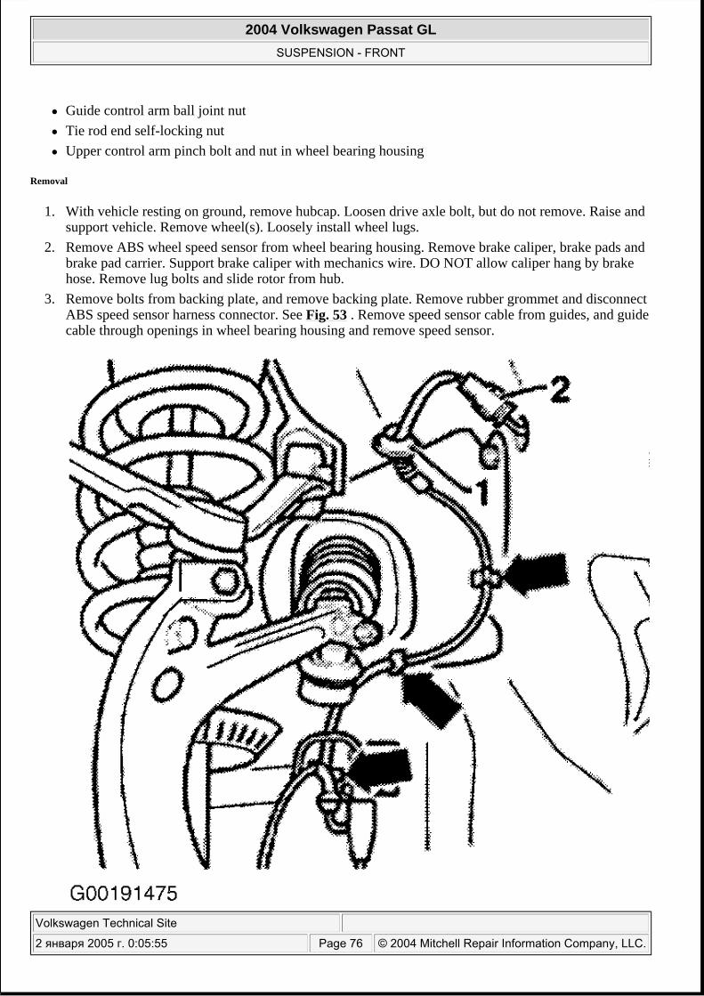
1. With vehicle resting on ground, remove hubcap. Loosen drive axle bolt, but do not remove. Raise and support vehicle. Remove wheel(s). Loosely install wheel lugs.
2. Remove ABS wheel speed sensor from wheel bearing housing. Remove brake caliper, brake pads and brake pad carrier. Support brake caliper with mechanics wire. DO NOT allow caliper hang by brake hose. Remove lug bolts and slide rotor from hub.
3. Remove bolts from backing plate, and remove backing plate. Remove rubber grommet and disconnect ABS speed sensor harness connector. See Fig. 53 . Remove speed sensor cable from guides, and guide cable through openings in wheel bearing housing and remove speed sensor.
2004 Volkswagen Passat GL
SUSPENSION - FRONT
Volkswagen Technical Site
2 января 2005 г. 0:05:55 Page 76 © 2004 Mitchell Repair Information Company, LLC.
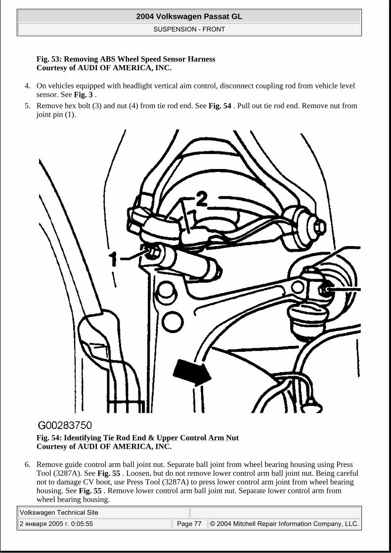
Fig. 53: Removing ABS Wheel Speed Sensor Harness Courtesy of AUDI OF AMERICA, INC.
4. On vehicles equipped with headlight vertical aim control, disconnect coupling rod from vehicle level sensor. See Fig. 3 .
5. Remove hex bolt (3) and nut (4) from tie rod end. See Fig. 54 . Pull out tie rod end. Remove nut from joint pin (1).
Fig. 54: Identifying Tie Rod End & Upper Control Arm Nut Courtesy of AUDI OF AMERICA, INC.
6. Remove guide control arm ball joint nut. Separate ball joint from wheel bearing housing using Press Tool (3287A). See Fig. 55 . Loosen, but do not remove lower control arm ball joint nut. Being careful not to damage CV boot, use Press Tool (3287A) to press lower control arm joint from wheel bearing housing. See Fig. 55 . Remove lower control arm ball joint nut. Separate lower control arm from wheel bearing housing.
2004 Volkswagen Passat GL
SUSPENSION - FRONT
Volkswagen Technical Site
2 января 2005 г. 0:05:55 Page 77 © 2004 Mitchell Repair Information Company, LLC.
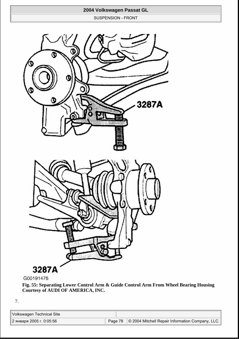
Fig. 55: Separating Lower Control Arm & Guide Control Arm From Wheel Bearing Housing Courtesy of AUDI OF AMERICA, INC.
7.
2004 Volkswagen Passat GL
SUSPENSION - FRONT
Volkswagen Technical Site
2 января 2005 г. 0:05:56 Page 78 © 2004 Mitchell Repair Information Company, LLC.
Remove upper control arm nut and bolt. Pull both upper control arm upward from wheel bearing housing. Swing wheel bearing housing away to side; when doing this remove drive axle pin from wheel hub. Take off wheel bearing housing.
Installation
1. Install wheel bearing housing. Install lower control arm and control arm ball joints into wheel bearing housing.
2. Screw on NEW self-locking nut on lower control arm and guide control arm ball joints. Tighten to specification. See TORQUE SPECIFICATIONS . Counter hold joint pin with 4 mm hex key, if necessary.
3. Install outer drive axle joint into hub. HAND tighten with a new hex bolt. Bolt will be final tightened with vehicle on ground.
4. Insert upper control arms into wheel bearing housing. Insert NEW bolt and tighten NEW nut. See TORQUE SPECIFICATIONS .Push upper control arms down as far as possible while tightening bolts.
5. Install tie rod end into wheel bearing housing. Tighten hex bolt. See TORQUE SPECIFICATIONS . Screw on NEW self-locking nut and tighten.
6. Install ABS speed sensor. Install brake backing plate. 7. Install disc and brake caliper.See TORQUE SPECIFICATIONS . 8. Install wheel and tighten wheel bolts. See TORQUE SPECIFICATIONS . 9. Lower vehicle to ground. Final tighten NEW drive axle collar bolt.
10. Check wheel alignment. See SPECIFICATIONS & PROCEDURES - PASSAT article in WHEEL ALIGNMENT.
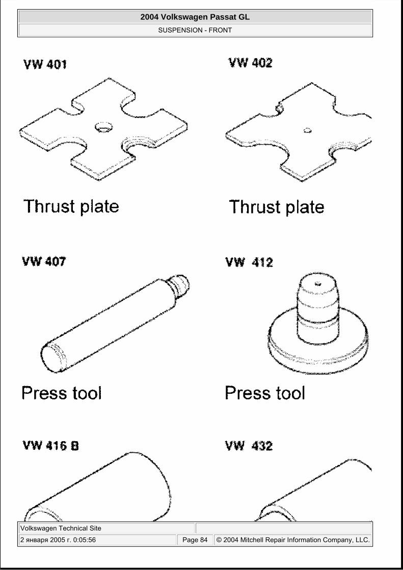
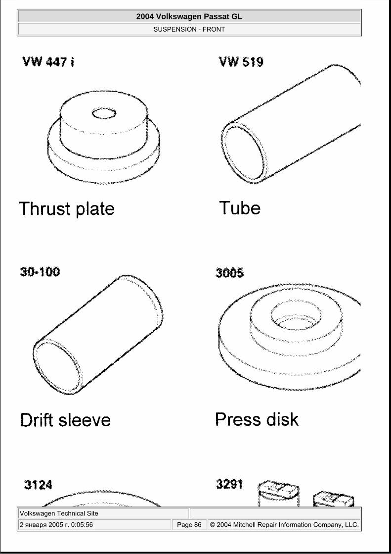
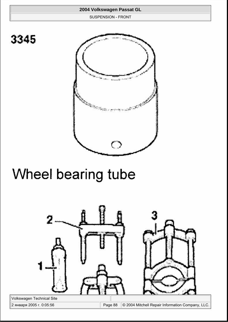
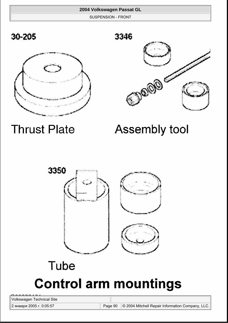
SPECIAL TOOLS
Use following illustrations in identifying special tools used during servicing. See Fig. 56 -Fig. 63 .
CAUTION: The slits in the wheel bearing housing must not be widened using a chisel or similar tool! If the hex bolt cannot be removed from the wheel bearing housing, then the hex bolt and control arms must be pressed out of wheel bearing housing. See SEPARATING CONNECTIONS BETWEEN UPPER CONTROL ARMS & WHEEL BEARING HOUSING .
2004 Volkswagen Passat GL
SUSPENSION - FRONT
Volkswagen Technical Site
2 января 2005 г. 0:05:56 Page 79 © 2004 Mitchell Repair Information Company, LLC.
2004 Volkswagen Passat GL
SUSPENSION - FRONT
Volkswagen Technical Site
2 января 2005 г. 0:05:56 Page 80 © 2004 Mitchell Repair Information Company, LLC.
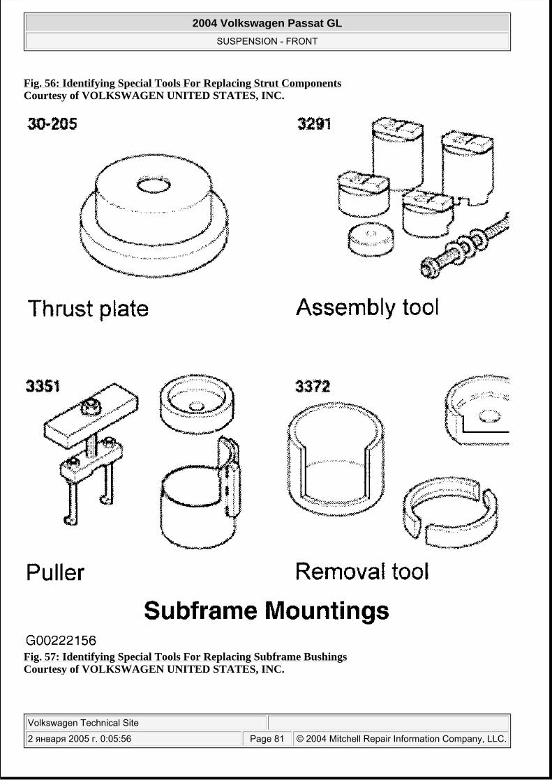
Fig. 56: Identifying Special Tools For Replacing Strut Components Courtesy of VOLKSWAGEN UNITED STATES, INC.
Fig. 57: Identifying Special Tools For Replacing Subframe Bushings Courtesy of VOLKSWAGEN UNITED STATES, INC.
2004 Volkswagen Passat GL
SUSPENSION - FRONT
Volkswagen Technical Site
2 января 2005 г. 0:05:56 Page 81 © 2004 Mitchell Repair Information Company, LLC.
2004 Volkswagen Passat GL
SUSPENSION - FRONT
Volkswagen Technical Site
2 января 2005 г. 0:05:56 Page 82 © 2004 Mitchell Repair Information Company, LLC.

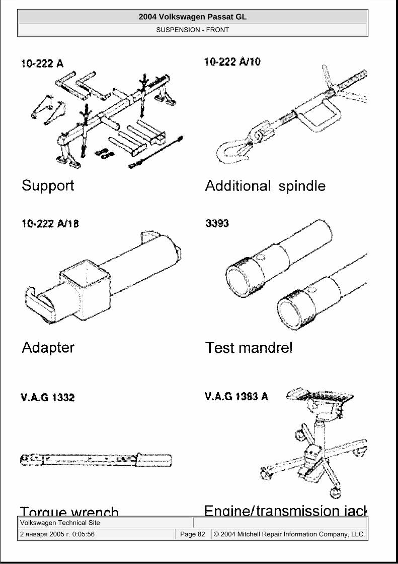
Fig. 58: Identifying Special Tools For Removing/Installing Subframe Courtesy of VOLKSWAGEN UNITED STATES, INC.
2004 Volkswagen Passat GL
SUSPENSION - FRONT
Volkswagen Technical Site
2 января 2005 г. 0:05:56 Page 83 © 2004 Mitchell Repair Information Company, LLC.
2004 Volkswagen Passat GL
SUSPENSION - FRONT
Volkswagen Technical Site
2 января 2005 г. 0:05:56 Page 84 © 2004 Mitchell Repair Information Company, LLC.

Fig. 59: Identifying Special Tools For Replacing Wheel Bearing (1 Of 3) Courtesy of VOLKSWAGEN UNITED STATES, INC.
2004 Volkswagen Passat GL
SUSPENSION - FRONT
Volkswagen Technical Site
2 января 2005 г. 0:05:56 Page 85 © 2004 Mitchell Repair Information Company, LLC.
2004 Volkswagen Passat GL
SUSPENSION - FRONT
Volkswagen Technical Site
2 января 2005 г. 0:05:56 Page 86 © 2004 Mitchell Repair Information Company, LLC.

Fig. 60: Identifying Special Tools For Replacing Wheel Bearing (2 Of 3) Courtesy of VOLKSWAGEN UNITED STATES, INC.
2004 Volkswagen Passat GL
SUSPENSION - FRONT
Volkswagen Technical Site
2 января 2005 г. 0:05:56 Page 87 © 2004 Mitchell Repair Information Company, LLC.
2004 Volkswagen Passat GL
SUSPENSION - FRONT
Volkswagen Technical Site
2 января 2005 г. 0:05:56 Page 88 © 2004 Mitchell Repair Information Company, LLC.

Fig. 61: Identifying Special Tools For Replacing Wheel Bearing (3 Of 3) Courtesy of VOLKSWAGEN UNITED STATES, INC.
2004 Volkswagen Passat GL
SUSPENSION - FRONT
Volkswagen Technical Site
2 января 2005 г. 0:05:57 Page 89 © 2004 Mitchell Repair Information Company, LLC.
2004 Volkswagen Passat GL
SUSPENSION - FRONT
Volkswagen Technical Site
2 января 2005 г. 0:05:57 Page 90 © 2004 Mitchell Repair Information Company, LLC.

Fig. 62: Identifying Special Tools For Replacing Lower Control Arm Bushings Courtesy of VOLKSWAGEN UNITED STATES, INC.
2004 Volkswagen Passat GL
SUSPENSION - FRONT
Volkswagen Technical Site
2 января 2005 г. 0:05:57 Page 91 © 2004 Mitchell Repair Information Company, LLC.
2004 Volkswagen Passat GL
SUSPENSION - FRONT
Volkswagen Technical Site
2 января 2005 г. 0:05:57 Page 92 © 2004 Mitchell Repair Information Company, LLC.

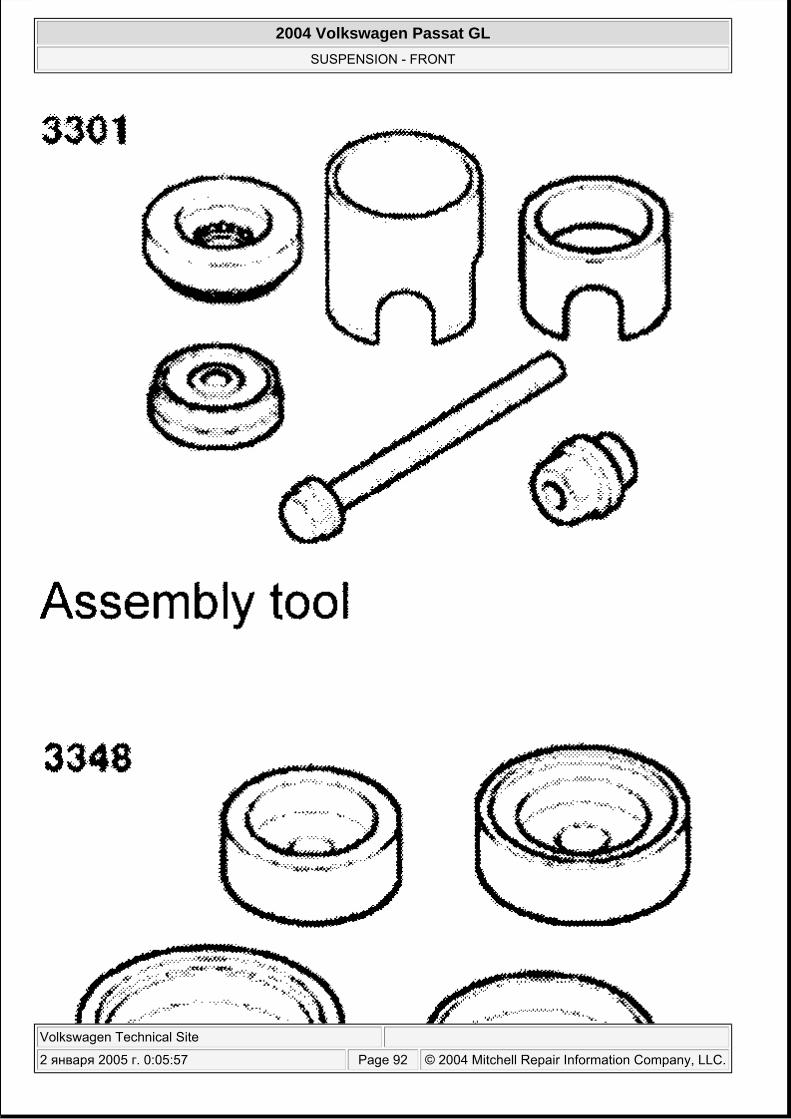
Fig. 63: Identifying Special Tools For Replacing Upper Control Arm Bushings Courtesy of VOLKSWAGEN UNITED STATES, INC.
TORQUE SPECIFICATIONS
TORQUE SPECIFICATIONS Application Ft. Lbs. (N.m) Brake Caliper Guide Pin-To-Caliper Carrier (Single Piston Caliper) 18 (25) Guide Pin-To-Caliper Carrier (2-Piston Caliper) 18 (25) Caliper-To-Wheel Bearing Housing (2-Piston Fixed Caliper) 140 (190) Drive Axle Collar Bolt M14 (Tighten With Wheels On Ground) (1)
Step 1 85 (115) Step 2 Plus 180° (1/2) Turn
Drive Axle Collar Bolt M16 (Tighten With Wheels On Ground) (1)
Step 1 140 (190) Step 2 Plus 180° (1/2) Turn
Driveshaft Flange-To-Transmission Flange Self-Locking Bolt (1)
AWD Vehicles 41 (55) Guide Control Arm-To-Subframe Nut & Bolt (1)(2)
Step 1 60 (80) Step 2 Plus 180° (1/2) Turn
Guide Control Arm Ball Joint Self-Locking Nut (1)
Flange Nut 74 (100) Combination Nut 92 (125)
Lower Control Arm Ball Joint Nut (1)
Flange Nut 74 (100) Combination Nut 92 (125)
Lower Control Arm-To-Subframe Nut (1) , (2)
Step 1 60 (80) Step 2 Plus 90° (1/4) Turn
Mounting Bracket-To-Body Bolt 55 (75) Stabilizer Bar Lower Coupling Link Self-Locking Nut (1)
Step 1 30 (40) Step 2 Plus 90° (1/4) Turn
Stabilizer Bar-To-Subframe Bracket Nut 18 (25) Strut Piston Rod Nut 37 (50) Strut-To-Mounting Bracket Nuts (1) 16 (22)
Strut-To-Lower Control Arm Nut (1) , (2) 66 (90)
Subframe Bolt (Front, M10 x 70) (1) 55 (75)
Subframe Bolt (Front, M12 x 110) (1)
2004 Volkswagen Passat GL
SUSPENSION - FRONT
Volkswagen Technical Site
2 января 2005 г. 0:05:57 Page 93 © 2004 Mitchell Repair Information Company, LLC.
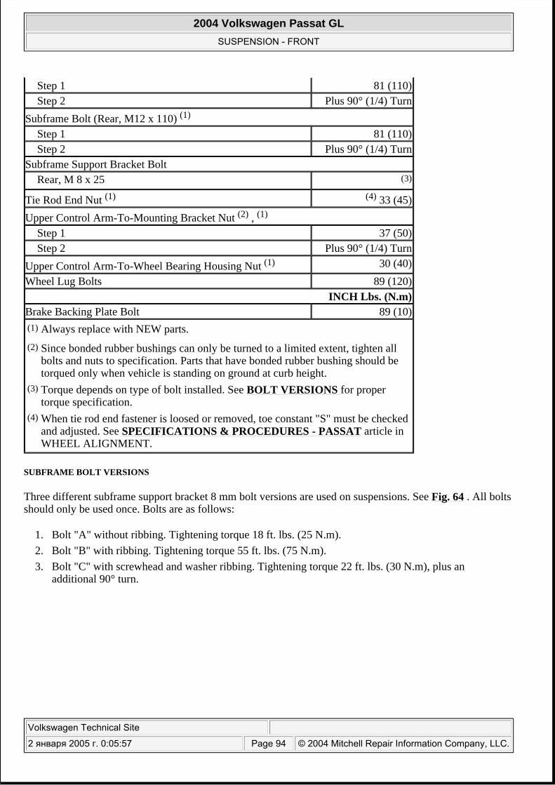
SUBFRAME BOLT VERSIONS
Three different subframe support bracket 8 mm bolt versions are used on suspensions. See Fig. 64 . All bolts should only be used once. Bolts are as follows:
1. Bolt "A" without ribbing. Tightening torque 18 ft. lbs. (25 N.m). 2. Bolt "B" with ribbing. Tightening torque 55 ft. lbs. (75 N.m). 3. Bolt "C" with screwhead and washer ribbing. Tightening torque 22 ft. lbs. (30 N.m), plus an
additional 90° turn.
Step 1 81 (110) Step 2 Plus 90° (1/4) Turn
Subframe Bolt (Rear, M12 x 110) (1)
Step 1 81 (110) Step 2 Plus 90° (1/4) Turn
Subframe Support Bracket Bolt Rear, M 8 x 25 (3)
Tie Rod End Nut (1) (4) 33 (45) Upper Control Arm-To-Mounting Bracket Nut (2) , (1)
Step 1 37 (50) Step 2 Plus 90° (1/4) Turn
Upper Control Arm-To-Wheel Bearing Housing Nut (1) 30 (40) Wheel Lug Bolts 89 (120)
INCH Lbs. (N.m)Brake Backing Plate Bolt 89 (10) (1) Always replace with NEW parts.(2) Since bonded rubber bushings can only be turned to a limited extent, tighten all
bolts and nuts to specification. Parts that have bonded rubber bushing should be torqued only when vehicle is standing on ground at curb height.
(3) Torque depends on type of bolt installed. See BOLT VERSIONS for proper torque specification.
(4) When tie rod end fastener is loosed or removed, toe constant "S" must be checked and adjusted. See SPECIFICATIONS & PROCEDURES - PASSAT article in WHEEL ALIGNMENT.
2004 Volkswagen Passat GL
SUSPENSION - FRONT
Volkswagen Technical Site
2 января 2005 г. 0:05:57 Page 94 © 2004 Mitchell Repair Information Company, LLC.
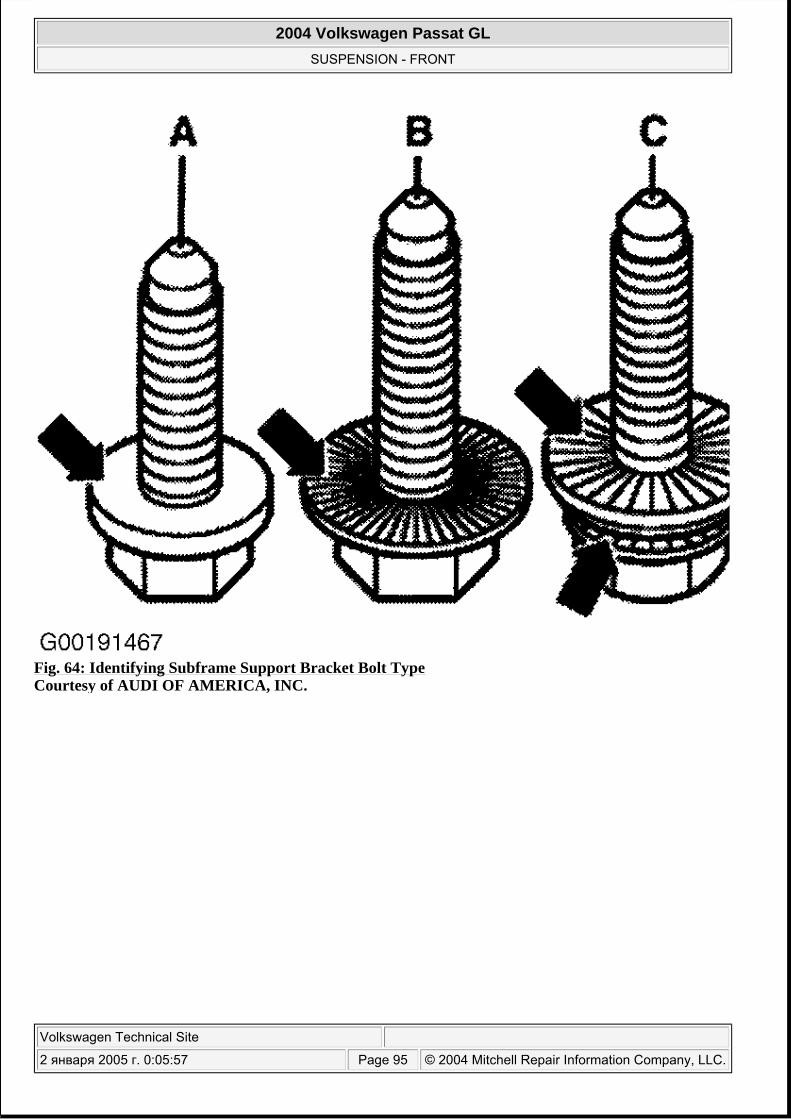
Fig. 64: Identifying Subframe Support Bracket Bolt Type Courtesy of AUDI OF AMERICA, INC.
2004 Volkswagen Passat GL
SUSPENSION - FRONT
Volkswagen Technical Site
2 января 2005 г. 0:05:57 Page 95 © 2004 Mitchell Repair Information Company, LLC.
Recommended