www.jimmeyerracing.com2795 SE 23rd • Lincoln City, OR 97367
Tech: 1-541-994-7717 • Order: 1-800-824-1752 • Fax: 1-541-994-2397
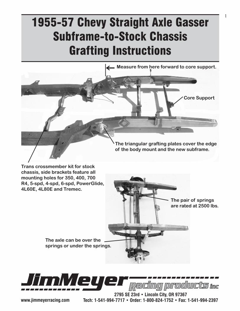
1955-57 Chevy Straight Axle GasserSubframe-to-Stock Chassis
Grafting Instructions
1
Trans crossmember kit for stock chassis, side brackets feature all mounting holes for 350, 400, 700 R4, 5-spd, 4-spd, 6-spd, PowerGlide, 4L60E, 4L80E and Tremec.
Measure from here forward to core support.
Core Support
The triangular grafting plates cover the edge of the body mount and the new subframe.
The axle can be over the springs or under the springs.
The pair of springs are rated at 2500 lbs.

www.jimmeyerracing.com2795 SE 23rd • Lincoln City, OR 97367
Tech: 1-541-994-7717 • Order: 1-800-824-1752 • Fax: 1-541-994-2397
Parts Inventory Lists & Replacement Parts2
ASSEMBLING THE PARTSThe axle can be mounted above-or-below the springs, depending on the desired ride height. Start by mounting the rear of the springs to the subframe. On the front of the spring, install shackle bushings first, then use the shackles to mount the spring to subframe.
1st thing to do is read over the entire instructionsPlease note the spring perches must be WELDED to the axle before ANY driving is done. Hardware might vary slightly, but installation is the same.Suspension Components-2 - 2500lbs pair Leaf Springs4 - 9/16” x 3 1/4” GR8 Bolts8 - 9/16” Steel Flat Washers4 - 9/16” Nylock Nuts4 - Shackle Link Plates4 - Shackle Bushings2 - 1/2” x 3 1/4” GR8 Bolts2 - 1/2” Nylock Nuts2 - Spring Plates4 - U-Bolts8 - 1/2” Ex. Thick Washers8 - 1/2” Tall Nuts2 - Shocks4 - 1/2” x 1 3/4” GR8 Bolts2 - 1/2” Steel Flat Washers2 - 1/2” Nylock Nuts2 - 1/2” x 2 1/2” GR8 Bolts2 - 1/2” Int Tooth Lock Washer4 - 1/2” Flat Washers
Steering Components-1 - Vega Steering Box1 - Drop Pitman Arm1 - Drag Link1 - Cross Link2 - Left Hand Tie Rod Ends and Jam Nuts2 - Right Hand Tie Rod Ends and Jam Nuts2 - 7/16” x 1 1/4” GR8 Bolts1 - 7/16” x 1 1/2” GR8 Bolt3 - 7/16” Hi Collar Lock Washers1 - Axle2 - Spring Perches
*Hardware might vary slightly, but installa-tion is the same.

www.jimmeyerracing.com2795 SE 23rd • Lincoln City, OR 97367
Tech: 1-541-994-7717 • Order: 1-800-824-1752 • Fax: 1-541-994-2397
Before you install the axle, make sure the steering stops, welded to each end of the axle, are facing toward the rear of the car. Using the spring plate, perches, and U-bolts mount the axle to the leaf springs, allowing for movement to center the axle. It would be a good idea to get your caster set-up at this point. Support the weight of the vehicle at the approximate ride height, half your tire diameter. Between 5 and 8 degrees positive caster, top of king pins toward firewall, is ideal for a gasser set-up. Make sure the axle is centered and caster set before tacking the axle cradles to the axles. We recommend welding the inside of the cradle to the axle. It must be adequate to prevent the axle from rotating.
Tac-weld axle cradle to axle. To set the caster, have all the vehicle weight on all 4 wheels. A mag-netic angle finder can be placed on the front of the king pin boss. Tilt the top of the king pin toward the rear until 8° positive caster is achieved.
Install the steering box to the mounting plate. Be sure to center the steering box before installing the pitman arm. Install the pitman arm, the splines are tapered so it’s a good idea to tighten the bolt with-out the lock wash for the first time to help seat the pitman arm, then install the lock washer. Install the king pin and mount the spindle assemblies to the axle. BE SURE TO INSTALL AND TIGHTEN THE SET SCREW, install the cross link, longer, be-
tween the steering arm’s forward hole on right steering arm. Adjust your toe-in at this point, to achieve 1/16”-1/8” toe-in. Install the drag link, between the pitman arm and the right side rearward hole in the steering arm. Check all the moving parts for clearance.
Steeringstops tothe rear.
SetScrew
3

www.jimmeyerracing.com2795 SE 23rd • Lincoln City, OR 97367
Tech: 1-541-994-7717 • Order: 1-800-824-1752 • Fax: 1-541-994-2397
INSTALLING THE SUBFRAME4
The goal is to have both the top of the subframe and the center main frame rails parallel with each other
The main (center) frame rails must be par-allel with the floor or table. Mark all 4 chas-sis corners on the floor or table.
Measure from the stock core support holes
back 32 1/4” to the bar placed
flush with the rear of the
body mount bracket shown.
Before cutting, weld a section of box-tube between the rails as shown. Use at least a 1” box tube to keep the rails stable.
From the rear of the body mount bracket shown, measure forward 4”. Using a square draw the line on the rails 90° to the floor or table.
12
3
4
5
6Plumb-Bob
Angle Finders
MagneticDigital

www.jimmeyerracing.com2795 SE 23rd • Lincoln City, OR 97367
Tech: 1-541-994-7717 • Order: 1-800-824-1752 • Fax: 1-541-994-2397
We recommend a Saws-All to do the cutting. Use what-ever you have and make clean cuts 90° to the floor/table. Grind the face until clean and even.
ALWAYS MEASURE IN AN “X” FASHION AND MEA-SURE FROM MORE THAN ONE LOCATION!
From the back of the body- mount bracket, measure to the new core support holes 32 1/4” or from the 4” mark at the rear of the body mount bracket (as shown in #5.) Also measure across, from each front frame end to the table or one of the marks on the floor. Measuring in an “X” fashion is always the best policy to make sure the new subframe is straight and parallel with the main rails.
Place the 2 x 4 box tube sub-frame into the old frame rails and measure from the new core support back 32 1/4” to the rear of the body mount bracket shown in photo #4, or the 4” mark shown in photo #5.
7
8
910
11
5

www.jimmeyerracing.com2795 SE 23rd • Lincoln City, OR 97367
Tech: 1-541-994-7717 • Order: 1-800-824-1752 • Fax: 1-541-994-2397
Measure in an “X” fashion from a common body mount hole on both sides of the frame to the front frame horn bumper mount hole.
Measure again from core sup-port back to the bar behind the body mount brackets.
Between the 2 different sized rails, we used a piece of scrap metal as spacers to keep it cen-tered side-to-side and top-to-bottom
To make the larger frame blend around the 2 x 4 box tube, you’ll have to draw and re-move a notch on each corner of the stock rails as shown for welding.
The Saws-All will do the quickest job cutting the pie shape out of the top of the old rails. Clamp it down and measure again before tac-welding the top.
Measure in an “X” from another common hole on the chassis and re-check the subframe.
12
13
14
15
16
6

www.jimmeyerracing.com2795 SE 23rd • Lincoln City, OR 97367
Tech: 1-541-994-7717 • Order: 1-800-824-1752 • Fax: 1-541-994-2397
Keep the rail centered in the hole. All 4-corners should get the same pie-cut removed so the frame rail edges can be pulled in to form a nice clean blend of metal. Use a clamp to pull the sides together and tac-weld. We used an 1/8” thick piece of scrap metal on one side between the 2 rails to keep the smaller subframe centered when clamping together to weld.
The 2 large body mounts on the outside of the frame on each side have 2 small tabs that need to be cut free to bend the stock frame edges into the new subframe. Reweld last after tacking the two together as shown.
Grafting plates are provided in the kit. The trianglar plates go on the outside-and-inside of the frame over the forward edges of the body mount shown. Place them between the two tabs as shown.
The 1/2-3/4” of metal in front of the body mount brack-et can be pulled together after the 2 outside tabs are cut free.
17
18
19
20
21
Using a cut-off wheel
Slice the 2 Webs. Free from body mount.
Tab
Tab
Place the grafting plates on the inside-and-outside of the rails.
7

www.jimmeyerracing.com2795 SE 23rd • Lincoln City, OR 97367
Tech: 1-541-994-7717 • Order: 1-800-824-1752 • Fax: 1-541-994-2397
JIM MEYER RACING PRODUCTSWARNING: Installation of any component or kit should only be performed by persons experienced in the installation and proper operation of SUSPENSION SYSTEMS. It is also the responsibility of the person installing any SUSPENSION SYSTEM or kit to de-termine the suitability of the component or kit for that particular application.
DISCLAIMER OF WARRANTY
Purchasers recognize and understand that suspension systems and equipment, and all parts, inventory and services manufactured and/or by JIM MEYER RACING PRODUCTS are exposed to many and varied conditions due to the manner in which they are installed and used. Purchasers and Jim Meyer Racing Products consciously desire to make their own bargain, irrespective of any court decision and purchasers agree upon good faith and in consid-eration for being allowed to purchase from Jim Meyer Racing Products said part or services. Purchasers expressly acknowledge and understand that Jim Meyer Racing Products does not make any affirmation of fact or promise to purchaser, which related to said parts, inventory, or services that becomes part of the basis of the bargain between Jim Meyer Racing Products and purchasers. Nor does Jim Meyer Racing Products make, or cause to be made to purchaser any description of the goods sold to purchaser, nor does Jim Meyer Racing Products make or cause to be made, a part of the basis of the bargain with purchasers, any description of affirmation of fact concerning any sample or suspension systems, and equipment inventory or service. As further consideration for purchasers using Jim Meyer Racing Products suspension systems and equipment any and all inventory and services, purchasers acknowledge that due to the differing conditions and circumstances under which all equipment and parts are installed and used, purchasers are not relying on Jim Meyer Racing Products skill or judgement to select or furnish the proper part or equipment. Purchasers expressly affirm they are relying upon their own skill or judgement to select and purchase suitable goods. Jim Meyer Racing Products makes no warranties whatsoever, expressed or implied, oral or written, to pur-chasers. There is no warranty of merchantability made to purchasers. Jim Meyer Racing Products further excludes any implied warranty of fitness with respect to suspension system and equipment, any and all inventory and service. It is expressly understood and agreed between purchasers and Jim Meyer Racing Products that as a part of bargain between Jim Meyer Racing Products and purchaser, and in consideration of doing business with each other, all purchasers take, select and purchase said suspension system, equipment, any and all inventory, or services from Jim Meyer Racing Products “as is” and “with all faults” and Jim Meyer Racing Products shall always provide purchasers with a full and complete opportunity to examine, at purchasers leisure and convenience, any suspension system and equipment, any and all inventory, or services when purchasing or contemplating purchasing from Jim Meyer Racing Products. If, and in the event that purchasers expressly or impliedly cause representations, or statements or affirma-tions of fact contrary to this disclaimer of all warranties, expressed or implied, then purchasers agree to indemnity and hold harmless Jim Meyer Racing Products in the event of any claim, demand, or legal action against Jim Meyer Racing Products by any purchaser. Purchasers understand and agree that no officer, director, employee, or salesman of Jim Meyer Racing Prod-ucts has any authority to make any statement contrary to the terms of this agreement. On the contrary, Jim Meyer Racing Products disavows any statement contrary to what is herein above written.
Inst
ruct
ions
by
Slat
tery
& A
ssoc
iate
s, 54
1-26
7-24
82 •
Prin
ting
by S
outh
Coa
st P
rintin
g, In
c. •
Gra
phic
s by
Che
ry H
urst
8
Recommended