1/4 RC PIPER J3 CUB
4
5
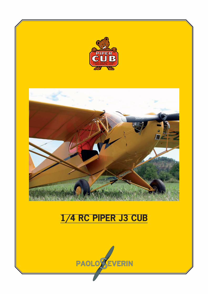
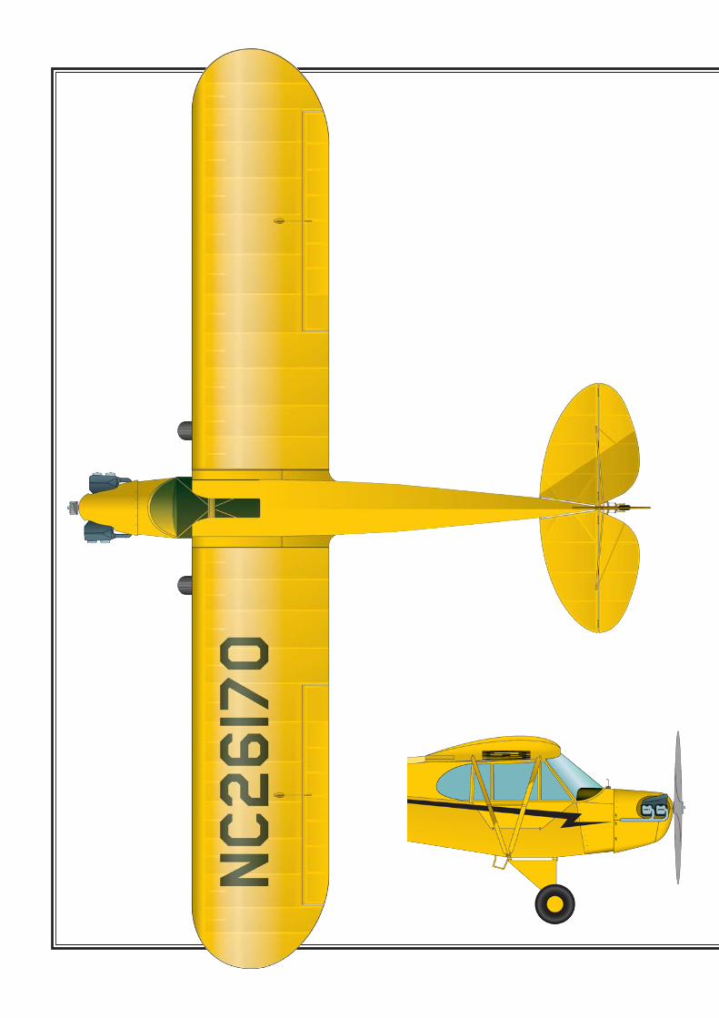
PIPER J3 CUB - 1937- 47
General specification:Wing span 35’ 2.5”
Lenght 22’ 4.5”Wing area 178.5 sq.ft.
Wing loading 6.16 lbs/sq.ft.Weight empty 680 lbs.Useful load 540 lbs.Top speed 87 mph
Landing speed 38 mphRange at cruise 220 miles
Maximum ceiling 12.000 feetFuel capacity 12 gals.
Oil capacity 1 galFuel consumption 4.46 gals/h
Power:Continenetal A-65-85
Lycoming 0-145Franklin 4AC-65
all 65 HP at 2500/2550 rpm
Coloring notes:Standard factory issue - overall Cub Yellow
(deep red - yellow), black trimother colors at customers request
1/4 SCALE RCWing span: 2680 mm. (105,5”)Lenght 1780 mm. (70”) approx.
Wing area: 100 dmq. (10.76 sq. ft.)Weight: 6/7 kg. (13/16 lbs.)
Power: 20/27 cc. (1.20/1.60 cu. in.) four stroke(1/10 scale 3 view drawing)
Reference source:Paul Matt, Historical Aviation Album
Piper Corporation, j3 Service Manual
Projected and drawn by Paolo SeverinJanuary 2004
4
FuselageAll the wooden parts can be glued directly on the paint using epoxy after a slight sanding. CA can be used as well with a bit of bicarbonate powder. Start preparing the fi rewall based on the engine selected (Photo 1), a good choice is the OS 160 twin, but also other good brands are available such as Saito, Magnum, etc. A single cylinder engine or even an electric motor can be used, in that case it’s possible to get some vacuum formed parts to riproduce the Continental 85 HP engine.The reference lines (Fig. 1) to center the engine are mar-ked on the former F1, the cuts to install the engine
mount, included in the kit, for the OS160 or 120 twin are also marked. The supplied engine mount can be adapted to install different engines or a new one can be made according to each one needs. The design does not contemplate, unlikely the full scale, the offsetting of the engine. The model will therefore feel slightly the trust of the engine and will tend to climb at high rpm. Use the following method if you want the plane to behave the same as the full scale J3 Cub. The engine can be offset anyway of about 1,5 degrees to the right and 2,5 degrees downwards so to have a consistent fl ying trim-ming at any rpm of the engine.
168 mm(6,62")
reference lines
F1
Fig. 1
Photo 1 Photo 2
5
Insert the F1 former on the fuselage, drill it and lock it in position with 4 M4 bolts (0,16” diam.)Glue the F2 former, made of 6 pieces, to the fuselage (Fig. 2), and the Former 3. Glue also the ribs F4, F5 and F6 and the part F7 (Photo3).Install now the fuel thank based on the engine selected. If the OS 160 twin is used, due to the low position of the carburetor, the fuel thank can rest on the servos tray plate kept in position with rubber bands. The same set up can be used for a single cylinder engine mounted upside down. Other installations with a carburator positioned higher require a specifi c holding plate for the fuel thank.Complete the top of the cockpit by gluing the 5x5mm (0,2”x0,2”) small longheron, the 0,8mm (0,03”) bir-chwood ply sheeting contoured as per drawing and the 10x10mm (0,4x0,4”) leading edge. Glue then the 0.8mm (0,03”) birchwood ply interior sheeting. As it’s all dry fi nish it all off and sand it (Phot 4/5/6).
Fig. 2
Photo 4
Photo 6
Photo 3
Photo 5
6
Glue a 10x20mm (0,4x0,8”) balsa list in between the F1 former and F2 former fi tting and positioning it as per drawing.Sheet it with 0,8 mm (0,03”), birchwood ply (Photo 7 and 8).Insert the left window posts using a 6x3 mm (0,24x0,12”) beech list and attach them in the cut outs of the F7 piece and to the tube as per drawing.Mount the rear windows frames by gluing the F8 and F9 parts as per drawing (Photo 9). Mount the karman fra-mes, don’t sheet them, by inserting a nylon sheet so that don’t get glued to the fuselage (Photo 10). The assem-bly of the fuselage structure is now completed.
Photo 7
Photo 8
Photo 9
Photo 10
7
WingsFold in two the wing drawing and attach it to the assem-bly board , lay a clear nylon sheet on top for protection. Prepare two small blocks gluing together the parts D1+D2+D3+D1 and D4+D5+D6+D4 (Photo 11). Attach the two ribs W1 and W2 to the assembly board inserting the two blocks just made and the parts A1, A2, A3 and A4. Insert the 4 longherons and also the ø 5 mm (0,2”) steel dowels and the stainless steel hooks (Photo 12/13/14).Glue the whole thing with slow curing epoxy.
Photo 11
Photo 13
Photo 14
Photo 12
8
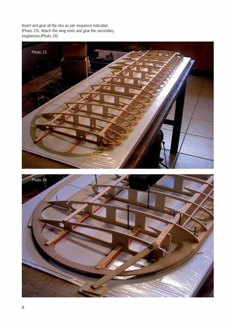
Insert and glue all the ribs as per sequence indicated (Photo 15). Attach the wing ends and glue the secondary longherons.(Photo 16)
Photo 15
Photo 16
9
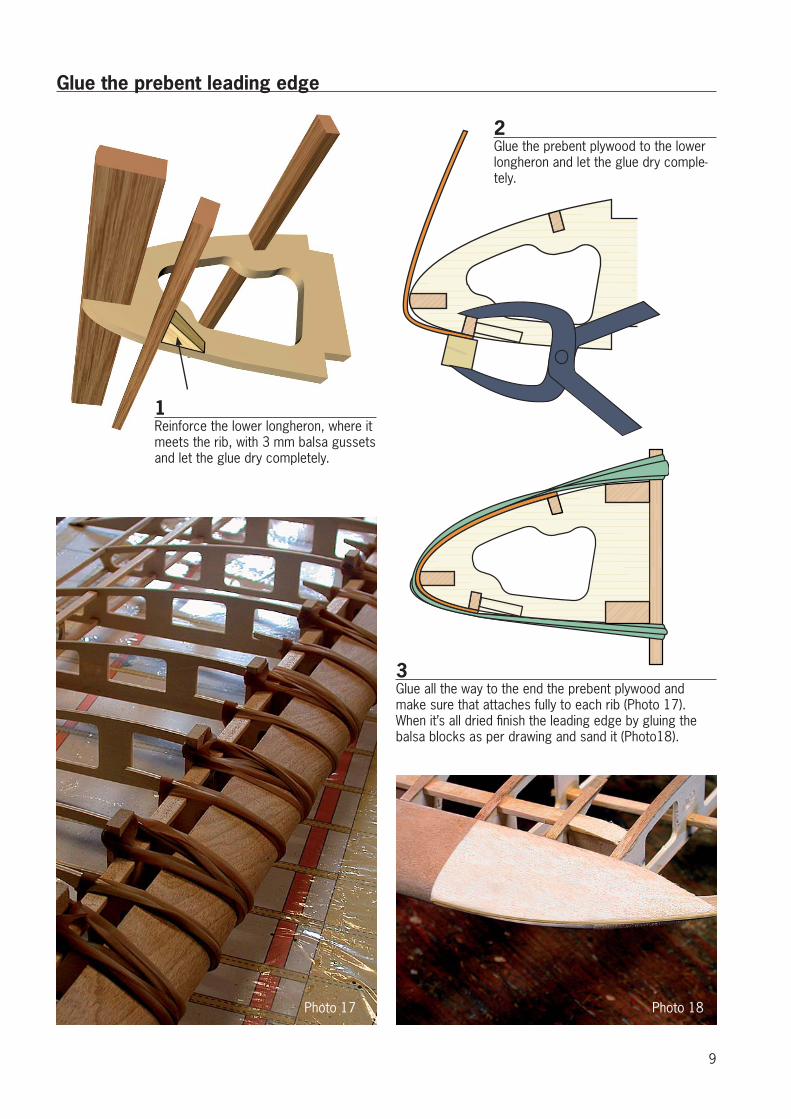
1Reinforce the lower longheron, where it meets the rib, with 3 mm balsa gussets and let the glue dry completely.
Glue the prebent leading edge
2Glue the prebent plywood to the lower longheron and let the glue dry comple-tely.
3Glue all the way to the end the prebent plywood and make sure that attaches fully to each rib (Photo 17). When it’s all dried fi nish the leading edge by gluing the balsa blocks as per drawing and sand it (Photo18).
Photo 18Photo 17
10
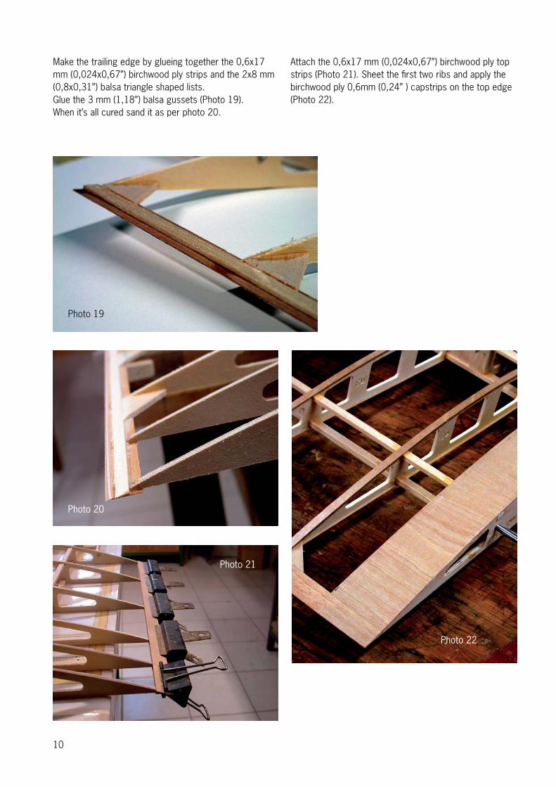
Make the trailing edge by glueing together the 0,6x17 mm (0,024x0,67”) birchwood ply strips and the 2x8 mm (0,8x0,31”) balsa triangle shaped lists.Glue the 3 mm (1,18”) balsa gussets (Photo 19).When it’s all cured sand it as per photo 20.
Attach the 0,6x17 mm (0,024x0,67”) birchwood ply top strips (Photo 21). Sheet the fi rst two ribs and apply the birchwood ply 0,6mm (0,24” ) capstrips on the top edge (Photo 22).
Photo 19
Photo 20
Photo 22
Photo 21
11
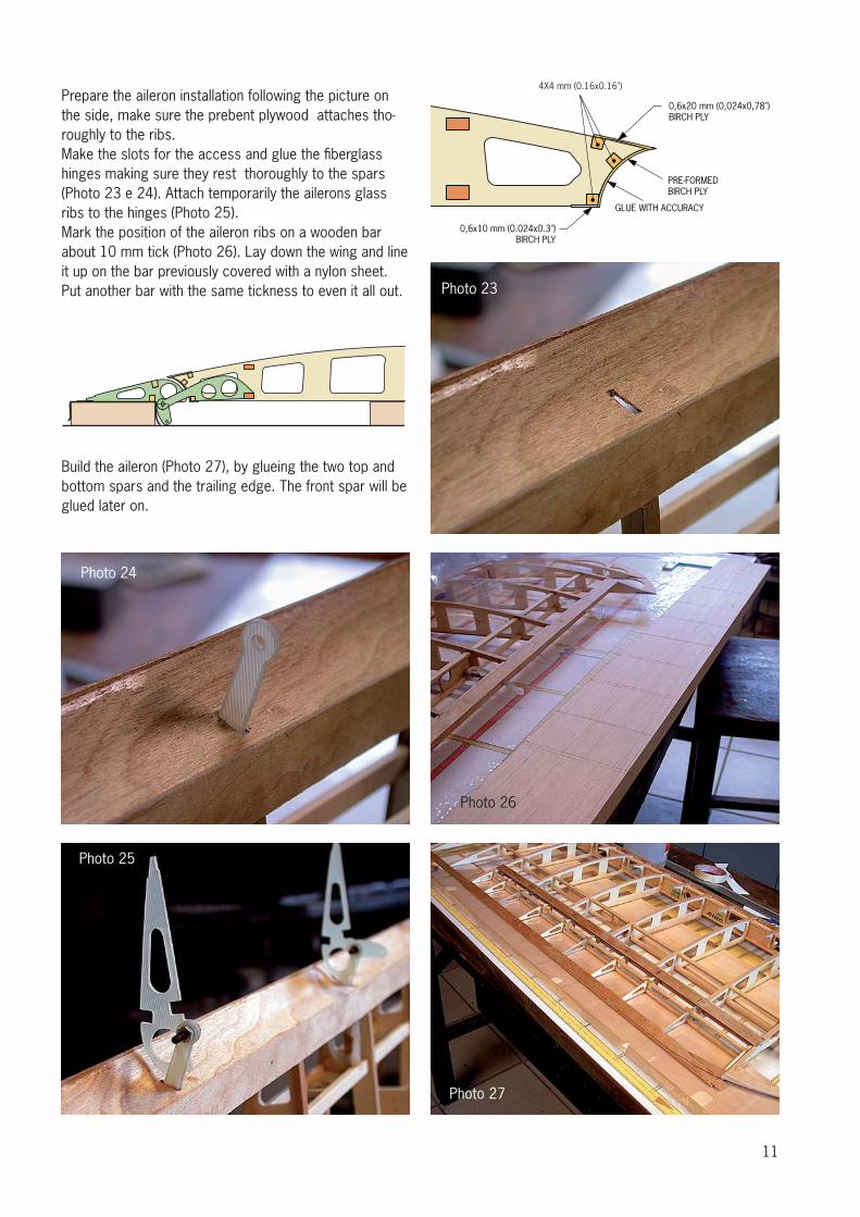
Prepare the aileron installation following the picture on the side, make sure the prebent plywood attaches tho-roughly to the ribs.Make the slots for the access and glue the fi berglass hinges making sure they rest thoroughly to the spars (Photo 23 e 24). Attach temporarily the ailerons glass ribs to the hinges (Photo 25).Mark the position of the aileron ribs on a wooden bar about 10 mm tick (Photo 26). Lay down the wing and line it up on the bar previously covered with a nylon sheet. Put another bar with the same tickness to even it all out.
Build the aileron (Photo 27), by glueing the two top and bottom spars and the trailing edge. The front spar will be glued later on.
PRE-FORMEDBIRCH PLY
GLUE WITH ACCURACY
0,6x20 mm (0,024x0,78") BIRCH PLY
0,6x10 mm (0.024x0.3")BIRCH PLY
4X4 mm (0.16x0.16")
Photo 23
Photo 24
Photo 25
Photo 26
Photo 27
12
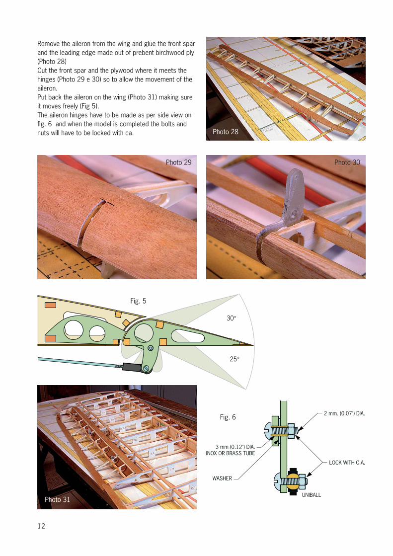
Remove the aileron from the wing and glue the front spar and the leading edge made out of prebent birchwood ply (Photo 28)Cut the front spar and the plywood where it meets the hinges (Photo 29 e 30) so to allow the movement of the aileron. Put back the aileron on the wing (Photo 31) making sure it moves freely (Fig 5).The aileron hinges have to be made as per side view on fi g. 6 and when the model is completed the bolts and nuts will have to be locked with ca.
WASHER
3 mm (0.12") DIA.INOX OR BRASS TUBE
LOCK WITH C.A.
2 mm. (0.07") DIA.
UNIBALL
Photo 28
Photo 31
Photo 29
Fig. 5
Fig. 6
Photo 30
13
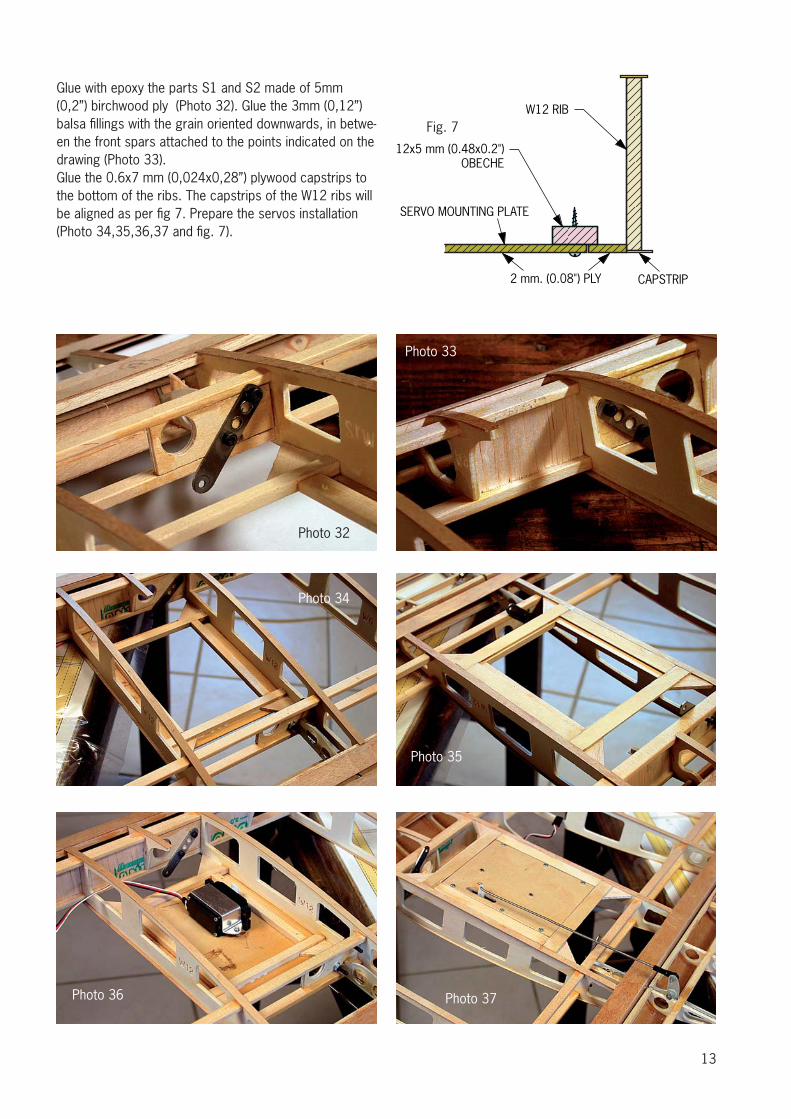
Glue with epoxy the parts S1 and S2 made of 5mm (0,2”) birchwood ply (Photo 32). Glue the 3mm (0,12”) balsa fi llings with the grain oriented downwards, in betwe-en the front spars attached to the points indicated on the drawing (Photo 33).Glue the 0.6x7 mm (0,024x0,28”) plywood capstrips to the bottom of the ribs. The capstrips of the W12 ribs will be aligned as per fi g 7. Prepare the servos installation (Photo 34,35,36,37 and fi g. 7).
2 mm. (0.08") PLY CAPSTRIP
W12 RIB
12x5 mm (0.48x0.2")OBECHE
SERVO MOUNTING PLATE
Photo 32
Fig. 7
Photo 34
Photo 35
Photo 37Photo 36
Photo 33
14
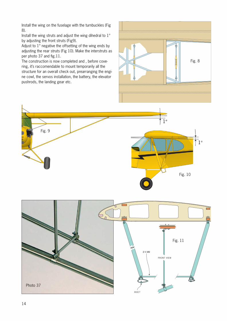
Install the wing on the fuselage with the turnbuckles (Fig 8).Install the wing struts and adjust the wing dihedral to 1° by adjusting the front struts (Fig9).Adjust to 1° negative the offsetting of the wing ends by adjusting the rear struts (Fig 10). Make the interstruts as per photo 37 and fi g.11.The construction is now completed and , before cove-ring, it’s raccomendable to mount temporarily all the structure for an overall check out, prearranging the engi-ne cowl, the servos installation, the battery, the elevator pushrods, the landing gear etc.
Fig. 8
Fig. 9
Fig. 10
FRONT VIEW
Ø 4 MM
RIVET
Fig. 11
Photo 37
15
16
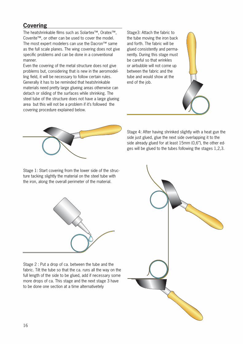
CoveringThe heatshrinkable fi lms such as Solartex™, Oratex™, Coverite™, or other can be used to cover the model.The most expert modelers can use the Dacron™ same as the full scale planes. The wing covering does not give specifi c problems and can be done in a conventional manner. Even the covering of the metal structure does not give problems but, considering that is new in the aeromodel-ling fi eld, it will be necessary to follow certain rules.Generally it has to be reminded that heatshrinkable materials need pretty large glueing areas otherwise can detach or sliding of the surfaces while shrinking. The steel tube of the structure does not have a large glueing area but this will not be a problem if it’s followed the covering procedure explained below.
Stage 1: Start covering from the lower side of the struc-ture tacking slightly the material on the steel tube with the iron, along the overall perimeter of the material.
Stage 2 : Put a drop of ca. between the tube and the fabric. Tilt the tube so that the ca. runs all the way on the full length of the side to be glued, add if necessary some more drops of ca. This stage and the next stage 3 have to be done one section at a time alternativetely
Stage3: Attach the fabric to the tube moving the iron back and forth. The fabric will be glued consistently and perma-nently. During this stage must be careful so that wrinkles or airbubble will not come up between the fabric and the tube and would show at the end of the job.
Stage 4: After having shrinked slightly with a heat gun the side just glued, glue the next side overlapping it to the side already glued for at least 15mm (0,6”), the other ed-ges will be glued to the tubes following the stages 1,2,3.
17
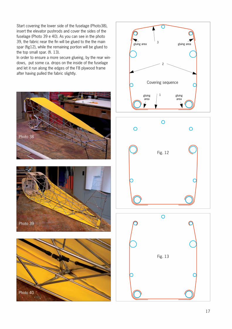
Start covering the lower side of the fuselage (Photo38), insert the elevator pushrods and cover the sides of the fuselage (Photo 39 e 40). As you can see in the photo 39, the fabric near the fi n will be glued to the the main spar (fi g12), while the remaining portion will be glued to the top small spar. (fi . 13).In order to ensure a more secure glueing, by the rear win-dows, put some ca. drops on the inside of the fuselage and let it run along the edges of the F8 plywood frame after having pulled the fabric slightly.
1
2
3gluing area gluing area
gluingarea
gluingarea
Covering sequence
Fig. 12
Fig. 13
Photo 38
Photo 39
Photo 40
18
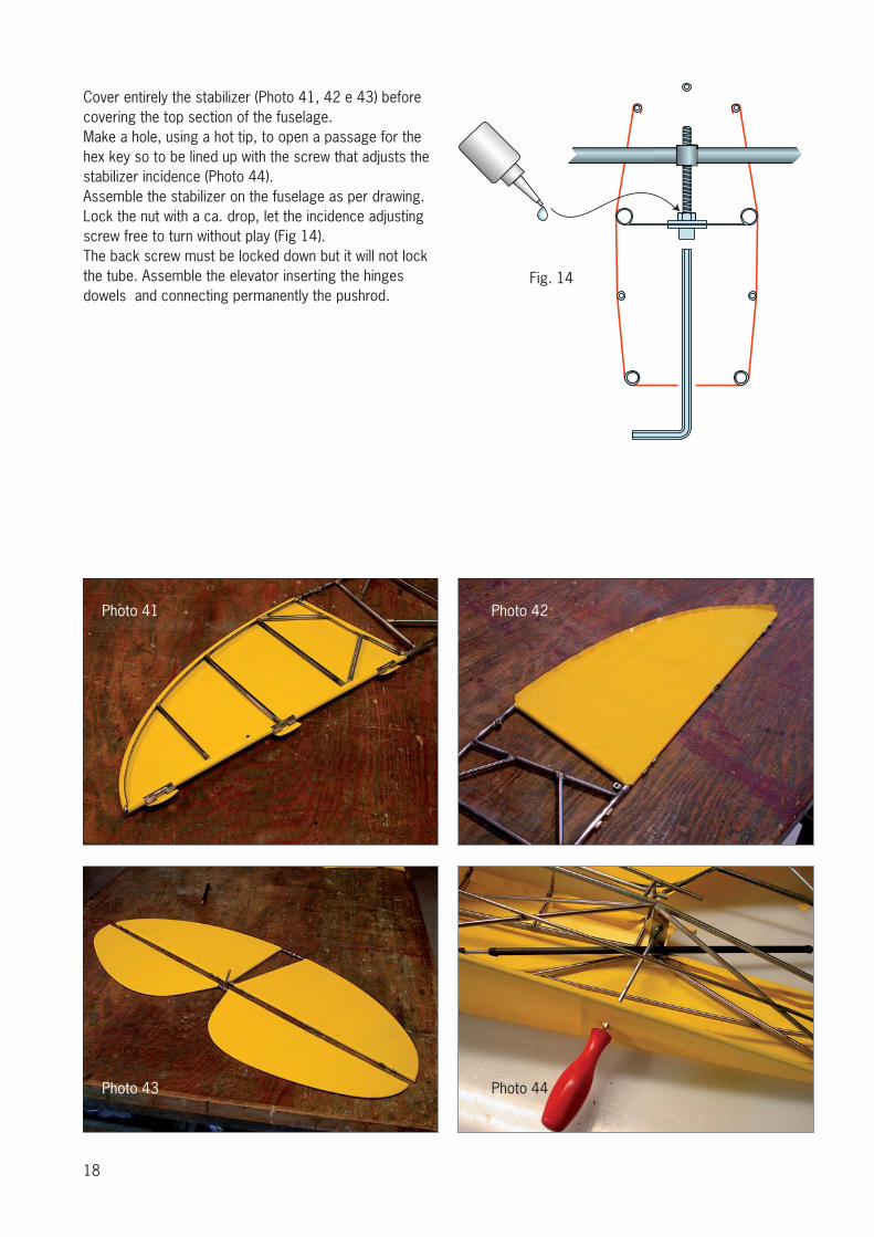
Cover entirely the stabilizer (Photo 41, 42 e 43) before covering the top section of the fuselage.Make a hole, using a hot tip, to open a passage for the hex key so to be lined up with the screw that adjusts the stabilizer incidence (Photo 44).Assemble the stabilizer on the fuselage as per drawing. Lock the nut with a ca. drop, let the incidence adjusting screw free to turn without play (Fig 14).The back screw must be locked down but it will not lock the tube. Assemble the elevator inserting the hinges dowels and connecting permanently the pushrod.
Fig. 14
Photo 41
Photo 43
Photo 42
Photo 44
19
Photo 45
Photo 47 Photo 48
Photo 49 Photo 50
Photo 46
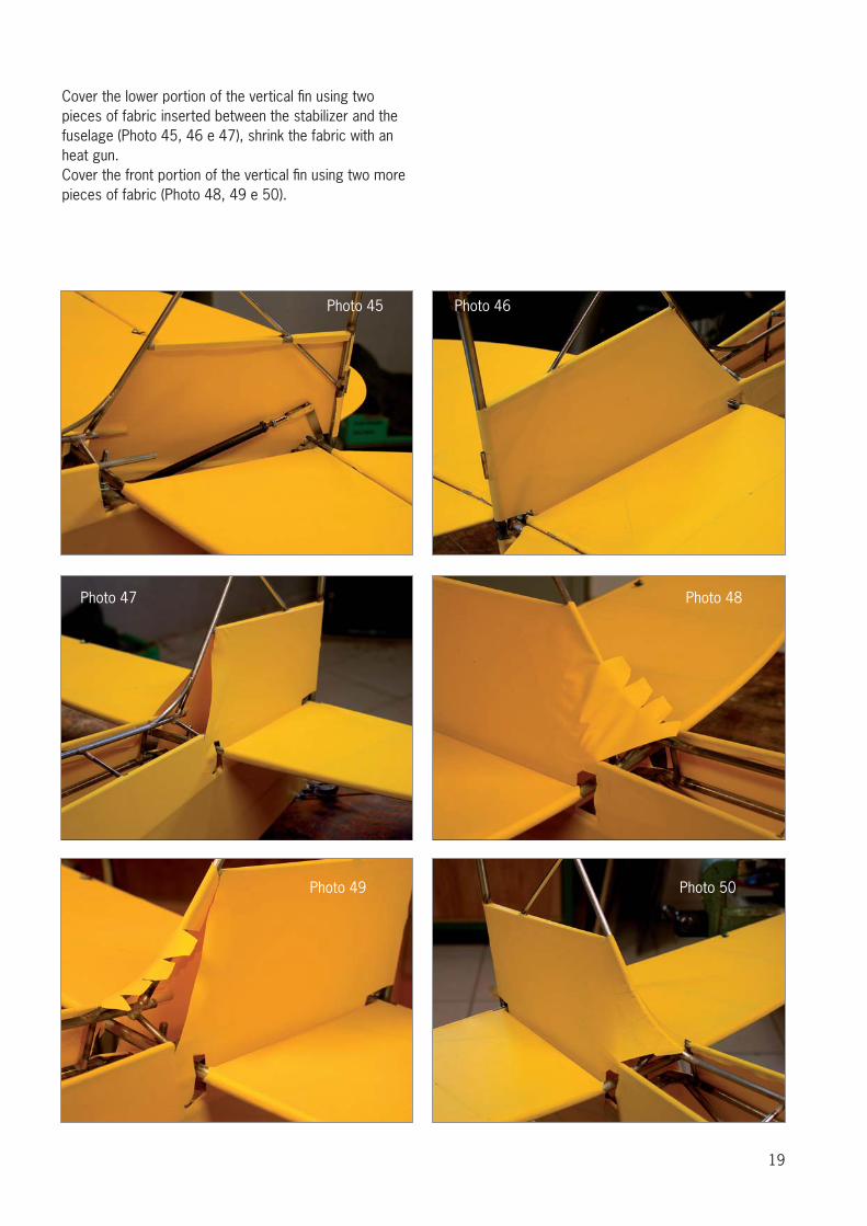
Cover the lower portion of the vertical fi n using two pieces of fabric inserted between the stabilizer and the fuselage (Photo 45, 46 e 47), shrink the fabric with an heat gun.Cover the front portion of the vertical fi n using two more pieces of fabric (Photo 48, 49 e 50).
20
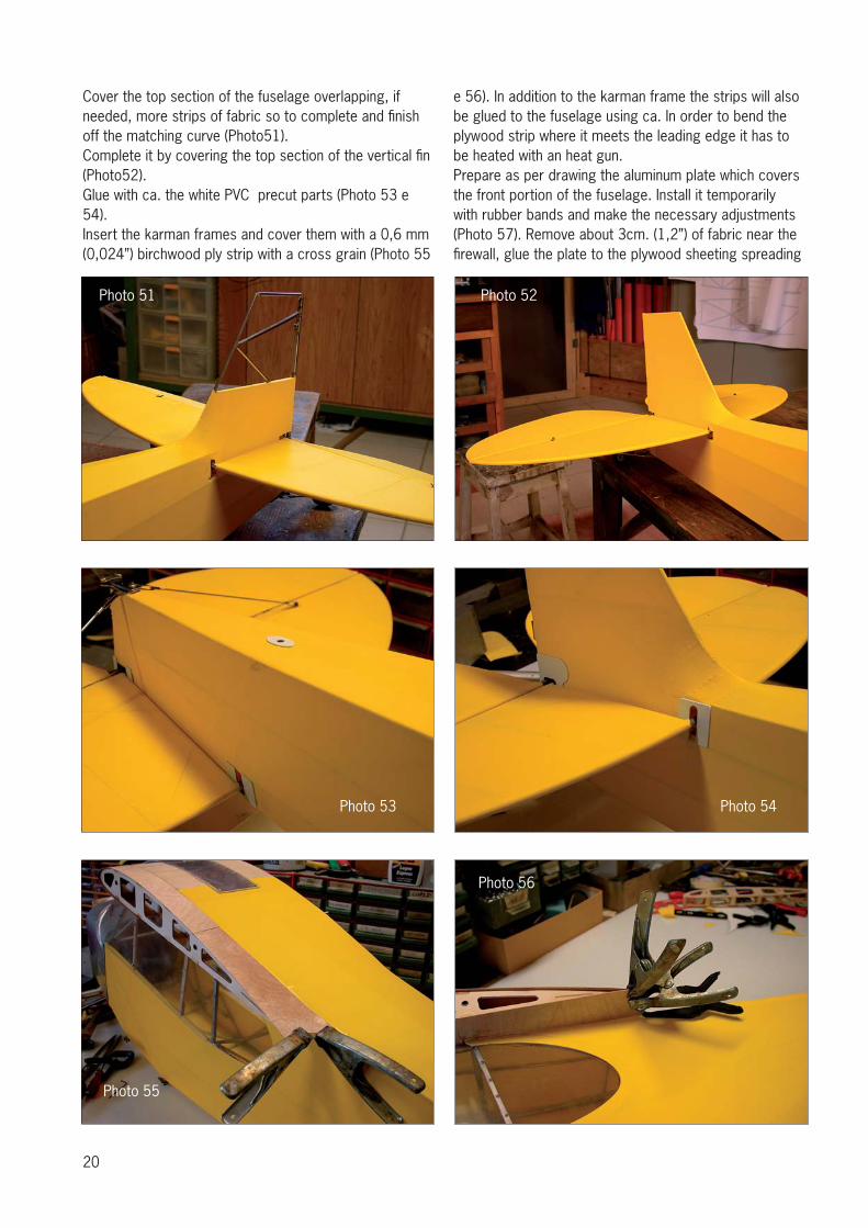
Cover the top section of the fuselage overlapping, if needed, more strips of fabric so to complete and fi nish off the matching curve (Photo51).Complete it by covering the top section of the vertical fi n (Photo52).Glue with ca. the white PVC precut parts (Photo 53 e 54).Insert the karman frames and cover them with a 0,6 mm (0,024”) birchwood ply strip with a cross grain (Photo 55
e 56). In addition to the karman frame the strips will also be glued to the fuselage using ca. In order to bend the plywood strip where it meets the leading edge it has to be heated with an heat gun. Prepare as per drawing the aluminum plate which covers the front portion of the fuselage. Install it temporarily with rubber bands and make the necessary adjustments (Photo 57). Remove about 3cm. (1,2”) of fabric near the fi rewall, glue the plate to the plywood sheeting spreading
Photo 51 Photo 52
Photo 53 Photo 54
Photo 56
Photo 55
21
a lot of slow curing epoxy only on the front portion (Photo 58).Prepare the front and the left side windows in one piece as per drawing, install it temporarily and make it fi t in place.Prepare the aluminum plate windshield frame as per dra-wing, screw it to the fuselage permanently and remove the windows glass (Photo59). Apply 4 small screws on each side of the covering plate(Photo 60).
The covering of the fuselage is done. Now, using the technique described on page 18, cover the rudder, the landing gear legs and the lower section of the door..The assembly is completed, fi nish now the model based on your experience.Paolo Severin
Photo 57
Photo 59 Photo 60
Photo 61
Photo 58
Paolo Severin srl
Head offi ce:Via Decorati al Valor Civile 57a
35142 PadovaItaly
Workshop:Via Monfalcone 11
35142 PadovaItaly
Phone: +39 (0) 49 8800329 - Fax 049 8800354Mobile: 347 0870248
www.paoloseverin.it
Recommended