Best Practices in HVAC Controls An overview of best practices, lessons learned and guidelines for optimizing HVAC controls to achieve significant energy and cost savings.
Publication Date: June 2012

Advanced Energy I Best Practices in HVAC Digital Controls I June 2012 1
Advanced Energy I Best Practices in HVAC Digital Controls I June 2012 2
TABLE OF CONTENTS
EXECUTIVE SUMMARY ............................................................................................................................... 4
OVERVIEW ................................................................................................................................................... 5
Using Controls to Manage Energy ............................................................................................................. 5
Commissioning/Re-Commissioning/Retro-commissioning ........................................................................ 5
Test Adjust and Balance ............................................................................................................................ 6
Assess Your In-House Expertise ............................................................................................................... 6
Research Options for Contracted Assistance ............................................................................................ 7
PHASE 1: COLLECT INFORMATION AND MAKE A MONITORING PLAN ............................................... 8
Create a Project Team and Select a Building ............................................................................................ 8
Facility Background and Operational Information ...................................................................................... 9
Outline Your Monitoring Strategy ............................................................................................................... 9
Energy Usage ........................................................................................................................................ 9
Comfort of Occupants .......................................................................................................................... 10
Changes in Occupancy and Weather .................................................................................................. 10
PHASE 2: COMPARE CURRENT BUILDING PERFORMANCE TO DESIGN INTENT ............................. 11
Evaluating System Function .................................................................................................................... 11
PHASE 3: APPLY OPTIMIZATION STRATEGIES AND EVALUATE IMPACT ........................................ 12
SERVICING AND MAINTENANCE ............................................................................................................. 14
BASIC OPTIMIZATION STRATEGIES THAT WORK ................................................................................. 14
Discussion ............................................................................................................................................... 14
STRATEGY ONE..................................................................................................................................... 14
Space Temperature Sensors ............................................................................................................... 16
STRATEGY TWO .................................................................................................................................... 17
Optimum Start and Stop ...................................................................................................................... 18
STRATEGY THREE ................................................................................................................................ 19
Ventilation and Outside Air ...................................................................................................................... 19
How Outdoor Air is Calculated: ............................................................................................................ 19
Advanced Energy I Best Practices in HVAC Digital Controls I June 2012 3
Air Flow Sensors.................................................................................................................................. 20
Dry Bulb Control .................................................................................................................................. 21
Enthalpy Controls ................................................................................................................................ 21
STRATEGY FOUR .................................................................................................................................. 21
Enthalpy Sensors................................................................................................................................. 22
STRATEGY FIVE .................................................................................................................................... 23
Supply Air Temperature Set Point ...................................................................................................... 23
Static Pressure Set Point .................................................................................................................... 23
STRATEGY SIX ...................................................................................................................................... 25
Chilled Water Temperature ................................................................................................................. 25
Hot Water Temperature ...................................................................................................................... 25
Condenser Water Temperature .......................................................................................................... 25
Outside Temperature Sensors ........................................................................................................ 26
STRATEGY SEVEN ................................................................................................................................ 27
Humidity and Dehumidification ........................................................................................................... 27
Relative Humidity Sensors .............................................................................................................. 27
STRATEGY EIGHT ................................................................................................................................. 28
Dynamic Reset or Demand Control Ventilation .................................................................................... 28
CO2 Control ......................................................................................................................................... 28
CO2 Sensors and Monitoring ............................................................................................................... 29
WORKS CITED ........................................................................................................................................... 30
RESOURCES .............................................................................................................................................. 31
Advanced Energy I Best Practices in HVAC Digital Controls I June 2012 4
EXECUTIVE SUMMARY Heating, ventilation and air conditioning (HVAC) systems are the single largest user of energy in most commercial buildings. From field work in K-12 schools, municipal buildings, colleges and universities and commercial property facilities, Advanced Energy has identified that optimizing HVAC controls can achieve significant energy and cost savings. HVAC direct digital control (DDC) systems, also referred to as Building Automation Systems (BAS), are being installed in newer buildings and many older facilities are being retrofitted with digital controls. When a new control system is installed, some entities do not have enough internal resources and knowledge to request the specific programming sequences which minimize energy usage. Also, these systems are installed with minimal training for technicians on how to set-up programming beyond occupied and unoccupied schedules. This guidebook was created to help overcome this knowledge barrier and to provide a practical education tool in creating better strategies to fit the needs of your organization and buildings. By implementing these best practices, you can:
• Improve occupant comfort; • Reduce comfort complaints; • Improve indoor air quality; • Educate staff on energy efficiency techniques; and • Improve energy efficiency to reduce energy usage, thus reducing overall energy costs.
Advanced Energy developed this guidebook for facility engineers, energy managers and HVAC controls technicians. It is assumed that if you are interested in this topic, you have some base knowledge about equipment used in HVAC systems. There are a wide variety of HVAC system designs and the topics tried to cover items that apply to most systems. By utilizing the best practices within this guidebook, you should be able to: • Prioritize where to focus your efforts in incorporating HVAC into your energy reduction strategy; and • Identify common misconceptions and challenges; and • Provide insight on how your organization may overcome those misconceptions. This guidebook will help you determine whether you have the skills and time on staff to obtain your energy goals or whether you need to hire a contractor. If you decide to hire a contractor, you will be equipped with the knowledge to ask for what you really need. The sections of this guidebook will walk you through using the BAS as a tool to reduce energy consumption and improve occupant comfort.
Advanced Energy I Best Practices in HVAC Digital Controls I June 2012 5
OVERVIEW When properly maintained, HVAC systems create a comfortable environment in any building – from schools, office buildings and industrial facilities to residential homes and apartment complexes. Different buildings have different requirements, though key to success is a properly installed system operated by qualified individuals who maintain consistent settings. Using Controls to Manage Energy There seems to be a trend in thinking that HVAC DDC systems are the solution to energy problems. However, it is important to realize that operating a HVAC system with DDCs will only save energy if the control system is installed, set and used properly. Operators need to have a basic understanding of how controls, such as dynamic reset and optimum stop/start (OSS), should be established and monitored. The main advantage of accessing the BAS when conducting an energy savings project is that the BAS can provide the data necessary to monitor energy consumption and room comfort conditions. Note this approach only works if you completely understand your system and the logic behind the controls. If your BAS lacks the needed sensor points, this guidebook may provide you with the necessary background to properly specify a new system when funding is available. Commissioning/Re-Commissioning/Retro-commissioning Commissioning is the process applied during design and construction that insures the systems in the building were installed according to the specifications and that the owner has all the information necessary to operate and maintain the building systems. Retro-commissioning is a similar process applied to existing buildings–either because the building was never commissioned or because the operation of the building has changed significantly over time. Re-commissioning can be done on a building that has been commissioned previously but time has led to the building not performing optimally. Re-commissioning is needed in the existing building stock for several reasons:
• Many buildings need to meet a higher level of performance today than when first built; • The possibility of higher electricity prices creates the need for more fully optimized operation and
control; • There is a marked increase in attention to indoor air quality and the delivery of new, higher
amounts of ventilation air to all spaces; • The cost-cutting emphasis in construction has made it difficult to deliver quality systems and
performance; and • The limited number and, sometimes, capabilities of maintenance staff, leads to deferral of
maintenance and sub-optimal operation of systems.
Advanced Energy I Best Practices in HVAC Digital Controls I June 2012 6
The estimated retro-commissioning cost is $0.50-$1.50 per square foot. This cost could be higher depending on the scope of the project and complexity of the building systems. According to case studies, most buildings report simple paybacks between two months and two years. While energy managers focus on the reduced energy usage and cost from re-commissioning, there are numerous other benefits that may justify spending money: • Reduced occupant complaints; • Increased occupant satisfaction; • Reduced maintenance staff time for emergencies and problem equipment; • Improved air quality; and • Improved productivity of occupants. Test Adjust and Balance Test adjust and balance (TAB) are important steps in the HVAC installation process that are often over looked or, unfortunately, neglected. Upon installation, the system must be balanced to ensure correct air and water flows are present. Balancing technicians will perform a variety of tasks, such as increasing/decreasing the speed of equipment fans to achieve desired air flow, or increasing/decreasing the speed of pumps to adjust water flow. Technicians performing test adjustments and balancing should be certified and should be following National Environmental Balancing Bureau (NEBB) or Associated Air Balance Council (AABC) guidelines. TAB is part of the commissioning or re-commissioning process. In many cases, the TAB process is done by the mechanical contractor. A commissioning or recommissioning agent represents the owner. Assess Your In-House Expertise It is important to realize that staff members are not often adequately trained to use the DDC system, do not understand the system’s full potential, or downsizing has made it impossible for staff to do anything but react to problems. Examples of incorrectly utilizing DDC systems:
• DDC system is often in override mode; • Operators manipulate the system to produce perfect space temperatures during both occupied and
unoccupied periods; and • Operators don’t trust the system and manually set heating valves for air handlers and change the
amount of outside air to maintain internal temperature setpoints. This lack of training, or understanding of how the system works, demonstrates how easily untrained staff do not utilize the DDC system to diagnose and/or fix problems. Instead, they tend to fall back on manually manipulating the system. (Churchill,Gregory, Oregon Office of Energy)
Advanced Energy I Best Practices in HVAC Digital Controls I June 2012 7
Research Options for Contracted Assistance In some cases, you will have a separate equipment distributor, mechanical contractor and a controls provider. Each controls vendor will have some proprietary information. Even with the top-notch experienced staff, you will likely need to contract with your controls vendor for some programming troubleshooting.
Advanced Energy I Best Practices in HVAC Digital Controls I June 2012 8
PHASE 1: COLLECT INFORMATION AND MAKE A MONITORING PLAN Create a Project Team and Select a Building To get started, you will need to identify all critical staff and create your project team including technicians, engineers and your controls vendor contact. Understanding the goals and objectives of the project, as well as the team’s knowledge and experience level, are critical to your success. Be sure to spend enough time sharing information to ensure the team agrees and understands all aspects of the project. If you have a large fleet of buildings, there are several good places to start in the selection of a building. Some factors that may indicate a building is a good candidate for improvements in HVAC Control include:
• High number of hot and cold calls, presence of space heaters in certain areas; • History of elevated humidity levels; • Higher energy intensity (kBTU/ft2) as indicated by monthly bills; and • Significant heating fuel usage in the spring, summer and fall for dehumidification.
We recommend starting with a building that has a building automation system and the controls must be:
• Currently at least 90 percent functional; and • Able to trend-log the time-varying system parameters.
Trending, or tracking repeated measurements over time, is very important not only to support heating and cooling setpoints but also in reviewing historical data to ensure systems are working properly. In control systems, trends are typically setup to show 15-to-60 minute data for 24-to-48 hours. Data may then be archived for long term storage. To be able to troubleshoot problems and respond to complaints, it is recommended trending capabilities be used for space temperature, relative humidity, air supply and return temperature, CO2, chilled water supply and return temperature, hot water supply and return temperature, damper positions, and valve positions. The strategies in this best practices guide will work if your system has been maintained properly and the sensors used to drive controls decisions are functional. Accurate data critical to functionality are:
• Return Air Temperature • Supply Air Temperature • Chilled Water Supply Temperature • Chilled Water Return Temperature • Static Pressure • Damper Position • Outside Air Temperature
Advanced Energy I Best Practices in HVAC Digital Controls I June 2012 9
Facility Background and Operational Information You will need to gather as much knowledge and background about your building as possible, such as:
• Drawings that include mechanical and plumbing schedules and layout; • Documentation on the sequence of operation; and • A copy of the programming or code for the BAS.
Before trying to optimize system performance, you need to understand how the HVAC system is currently programmed to operate. Go ahead and document staff knowledge about problem areas and their thoughts on sequence of operation, but note this will most likely require the services of the vendor who installed the system and wrote the program. The main objective is to document the setpoint and/or control strategy for each major piece of equipment. For example:
• What is the chilled water supply set point, and is it constant or is it programmed to change? • How is the outside air economizer programmed to operate? • How is the static pressure controller for the air handlers programmed to operate? • How is the supply temperature of the hydronic heating system programmed to operate? For
example, if there is outside air reset, what is the relationship between outside temperature and supply water temperature?
• At what water temperatures are the cooling tower fans set to come “on?” Outline Your Monitoring Strategy Energy Usage The first valuable energy usage calculation is an energy benchmark to determine the percent of overall load attributable to HVAC. An example of how to work through this is provided in Appendix A: Calculations. The next step is to identify the main energy-using components of the HVAC system. You should determine which of these is being monitored by the BAS. To be able to effectively evaluate how much energy is consumed by a building for HVAC, you should monitor at least 85 percent of the energy being consumed by the HVAC equipment. If the BAS does not monitor the power or energy consumption of these major components, a decision has to be made regarding installing temporary energy meters or upgrading the BAS to include additional metering. Cooling equipment that may need to be monitored includes chillers, cooling towers, major VAV air handlers and major VAV pumps. To meter the energy used for heating the building, you may also want to monitor the hot water output from a boiler or the natural gas input.
Advanced Energy I Best Practices in HVAC Digital Controls I June 2012 10
The goal here is to get at least 15 minute, 30 minute or hourly interval data to thoroughly understand how the building responds to both the internal load and the outdoor conditions. Two documents that may be helpful are available from Onset Computer Corporation, manufacturer of HOBO data loggers: Finding Hidden Energy Waste with Data loggers: 8 Cost Saving Opportunities and Monitoring HVAC Performance with Data Loggers. These documents are available free from their website: http://www.onsetcomp.com/resources/white_papers Comfort of Occupants The second step is to setup a monitoring strategy to determine the level of thermal comfort of the occupants. This task typically involves monitoring temperature and humidity levels in the occupied space. Hourly averages and daily maximum and minimum for five locations on each floor are typical: i.e., exterior areas (N, S, E, W) and core. Room temperatures are typically available, but humidity is usually not. If humidity is a concern inside the building, monitor the humidity of the return air. Refer to Example Problem 2 – Appendix A: Given trend-log data from multiple VAV boxes and fan-coil units, determine statistics for the temperature on that floor. Changes in Occupancy and Weather Since weather and building occupancy are the two major independent variable factors that influence building energy use, these two factors must also be monitored. If the BAS does not monitor outside air wet bulb and dry bulb conditions, then either expand the system or obtain data from a local weather station. The occupancy for many types of buildings is often rather constant, especially on a weekly basis. You need to determine if there are areas of the building that are totally unoccupied, or become unoccupied and document those findings.
Advanced Energy I Best Practices in HVAC Digital Controls I June 2012 11
PHASE 2: COMPARE CURRENT BUILDING PERFORMANCE TO DESIGN INTENT To evaluate whether your control system is functioning, it is necessary to check the calibration of the BAS critical sensors that control the major HVAC components. The most common way to check sensor calibration is to take a spot measurement with another meter. A better way is to install a temporary meter to record the parameter being measured by the BAS. This latter strategy can provide a 24-hour check on the calibration. Evaluating System Function With calibrated sensors and an idea of the sequence of operation programmed into the BAS, you can now determine if the HVAC system is actually functioning as it is “supposed to operate.” For example, is the supply water temperature of the hydronic heating system increasing as the outdoor temperature decreases (assuming it is supposed to)? To answer this question, trend logs of the outdoor temperature and the supply water temperature are created and the results are compared. If the results from the above operational system performance evaluation are negative, then there is either a programming error in the BAS or there is a problem with one of the sensors or controllers. The first step is to check the sensors and controllers and calibrate or replace them as needed. Sometimes the error is in the programming, and the vendor will have to be called in to correct that problem. Some key questions to evaluate from your data collected may include:
• Do the space temperatures setback as expected when building is unoccupied? • Does the mixed air temperature fall between the return air temperature and the outside air
temperature when the system is running for space occupancy? • Does the mixed air temperature track outside air temperature when economizing mode should be
enabled? • When the chilled water system comes on, does the chilled water temperature and supply air
temperature track accordingly? Are the temperatures well correlated with valve position? • Are there places where heating and cooling are running at the same time for the same space? • Is your system adjusting flow based on static pressure? • How are your cooling towers fans controlled?
Refer to Example Problem 3 in Appendix A: Given trend-log data for and air handling unit, analyze whether the economizer system is performing according to the sequence of operation.
Advanced Energy I Best Practices in HVAC Digital Controls I June 2012 12
PHASE 3: APPLY OPTIMIZATION STRATEGIES AND EVALUATE IMPACT In the first phase, you documented energy consumption, room comfort, building occupancy and weather. In the second phase, you evaluated the BAS functionality. The third phase is to develop and test strategies for reducing the energy consumption of the HVAC system. When the current BAS program only provides for manual set points, optimization strategies are limited to changing the set point and documenting the impact on energy use and room comfort. If the software allows for parameters to be automatically adjusted, then more sophisticated strategies can be evaluated. (Of course, BAS programs with manual setpoint control can always be revised to accommodate automatic set point adjustment.) Refer to Example Problem 4 in Appendix A: Given trend-log data for an air handling unit (AHU), determine the energy consumption of the chiller, air handler fans for one day of operation. One strategy for reducing HVAC energy consumption is to minimize the run-time of the chillers, air handlers, pumps and boilers. When this strategy is applied too much, the building gets too hot (or cold), the humidity in the building increases and mold and mildew may result, and indoor air quality becomes unacceptable because the building ventilation is inadequate. Optimization of the HVAC is a balancing act and each building is unique. The following strategies are examples of hypotheses that could be setup and tested. Operating setpoint and/or control strategies can be changed, and their impact on energy consumption and indoor comfort can be documented. Weather is the most significant independent variable. Keep in mind that optimal strategies for each season will probably be necessary.
Advanced Energy I Best Practices in HVAC Digital Controls I June 2012 13
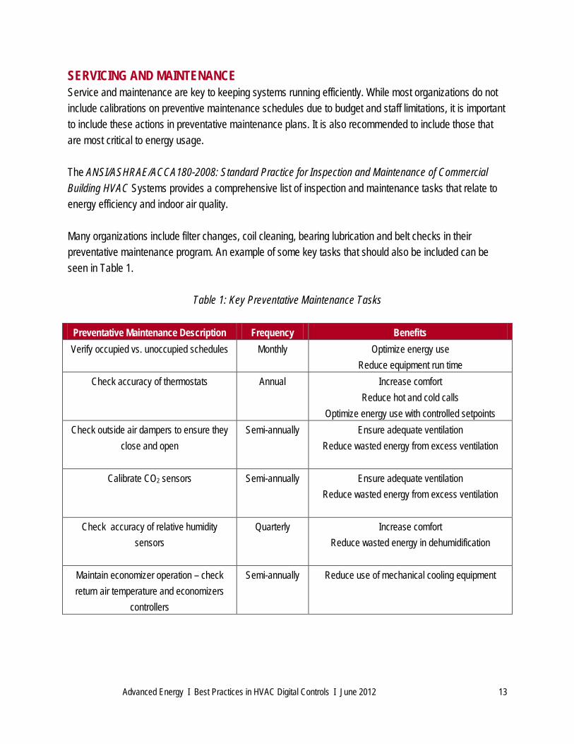
SERVICING AND MAINTENANCE Service and maintenance are key to keeping systems running efficiently. While most organizations do not include calibrations on preventive maintenance schedules due to budget and staff limitations, it is important to include these actions in preventative maintenance plans. It is also recommended to include those that are most critical to energy usage. The ANSI/ASHRAE/ACCA180-2008: Standard Practice for Inspection and Maintenance of Commercial Building HVAC Systems provides a comprehensive list of inspection and maintenance tasks that relate to energy efficiency and indoor air quality. Many organizations include filter changes, coil cleaning, bearing lubrication and belt checks in their preventative maintenance program. An example of some key tasks that should also be included can be seen in Table 1.
Table 1: Key Preventative Maintenance Tasks
Preventative Maintenance Description Frequency Benefits Verify occupied vs. unoccupied schedules Monthly Optimize energy use
Reduce equipment run time Check accuracy of thermostats Annual Increase comfort
Reduce hot and cold calls Optimize energy use with controlled setpoints
Check outside air dampers to ensure they close and open
Semi-annually Ensure adequate ventilation Reduce wasted energy from excess ventilation
Calibrate CO2 sensors Semi-annually Ensure adequate ventilation
Reduce wasted energy from excess ventilation
Check accuracy of relative humidity sensors
Quarterly Increase comfort Reduce wasted energy in dehumidification
Maintain economizer operation – check return air temperature and economizers
controllers
Semi-annually Reduce use of mechanical cooling equipment
Advanced Energy I Best Practices in HVAC Digital Controls I June 2012 14
BASIC OPTIMIZATION STRATEGIES THAT WORK
Discussion We all realize that everyone has a different comfort level and what’s “warm” to someone is “freezing” to someone else. And while energy may be the largest controllable expenditure in a building, employees’ salaries typically overshadow the energy cost. Additionally, research suggests occupant comfort can impact productivity. While some data argues that people are most productive at temperatures between 72°F and 77°F, in order to make energy efficiency a reality, systems should maintain the following set points:
• 70 to 72°F for occupied heating • 74 to 76°F for occupied cooling
Temperature is not the only measure of comfort and this can be a common problem in established temperature settings. ASHRAE Standard 55 discussed the six factors for thermal comfort:
1. Temperature 2. Relative humidity 3. Air velocity 4. Radiant temperature 5. Clothing 6. Metabolic rate
Note the last two may be difficult to address by your HVAC department.
• Relative Humidity The relative humidity must be maintained below 60 percent which may be problem in the summer cooling season. Too low of humidity in the winter in your building can make it seem colder to the
STRATEGY ONE Common Problem #1: We checked the temperature with our handheld thermometer in that area and it was within temperature range but the occupants still complain. We cannot keep people happy.
STRATEGY ONE: Commit to and enforce reasonable occupied heating and cooling set points for your building and its occupants. Recommendation Starting Point: Heating: 70-72°F Cooling: 74-76°F
Advanced Energy I Best Practices in HVAC Digital Controls I June 2012 15
occupants. If your space has high humidity levels in the summer or low humidity levels in the winter, refer to the sections about dehumidification and outside air requirements.
• Air Velocity If the air coming out of a supply duct is directly blowing on the person in the space, this may be the causal factor of being uncomfortable. Other sources of drafts should be checked.
• Radiant Temperature Spaces directly next to windows may cause specific problems. Those windows can cause excessive sunlight during some parts of the day making the space too hot or can radiate cold temperatures on cold days.
Sometimes publishing these setpoints can help reduce complaints, especially when occupants are more aware of energy usage and energy efficiency goals; however, in some cases, the published setpoints cause a backlash that the maintenance department cannot handle. There are a few approaches that may help you with this common problem.
• Start conservative and work from there. If you gradually adopt new guidelines and ease the occupants into your energy conservation policy, they may be more likely to accept the change.
• Ensure you are addressing complaints properly. People do not want to think their complaint has just been dismissed or their voice is not heard.
• Engage a member of management of administration to back up the policy. • Provide building occupants limited control over the HVAC operation – two degrees either
direction.
Providing people some level of control has been shown to help reduce complaints.
STRATEGY ONE Common Problem #2: Our management adopted an energy policy and we published our setpoints. We were overwhelmed with complaints to the maintenance department and no matter what we do occupants tamper with thermostats or want an exemption.
Advanced Energy I Best Practices in HVAC Digital Controls I June 2012 16
Do not encourage simultaneous heating and cooling with setpoints too close together for the system design. It is best to determine the adequate dead band to eliminate simultaneous heating and cooling for local thermostats. As such, the temperature difference between heating and cooling mode may have to be increased. Space Temperature Sensors Computers or other types of equipment that generates heat should not be placed under the thermostat. Temperature sensors should not be blocked by furniture. Most organizations agree that it is best practice to have central temperature control, but allow the occupant to adjust the setting up or down by two degrees.
STRATEGY ONE Common Problem #3: Setpoints and system designs encourage simultaneous heating and cooling.
Advanced Energy I Best Practices in HVAC Digital Controls I June 2012 17
To ensure a better understanding of the system’s operating schedule, it may make more sense to change the nomenclature in regards to on/off and stop/start to occupied and unoccupied.
• Occupied: the system will maintain the defined temperature setpoint. The system may also have a relative humidity or carbon dioxide setpoint. Outside air dampers are open and/or adjustable.
• Unoccupied: also referred to as night setback. The control system allows the temperature to rise or fall away from the occupied setpoint. Outdoor air dampers are closed.
Two of the best opportunities to save energy in existing facilities are proper scheduling and occupied/unoccupied setpoints. A graphical interface on the control system should display the schedule, which should be easy to access or change by limited authorized personnel. Recommended best practices for scheduling include: (Murphy 2009)
• Utilize separate time-of-day schedules for areas with different usage patterns; • Combine time-of-day schedule with occupancy sensors; • Use timed override buttons instead of starting systems earlier and later; • Utilize unoccupied economizing in addition to occupied economizing. Unoccupied economizing
uses air during unoccupied hours to cool the building when the outdoor temperature is less than the indoor temperature;
• Add a humidity sensor for outside air; and • Use a time-of-day schedule for ventilations for areas with predictable schedules (e.g.,
cafeterias and gyms). Recommended unoccupied setpoints:
Heating: 55 to 60°F Cooling: 85°F
STRATEGY TWO: Check that the occupied schedule is optimized for the current occupancy of your building. Utilize temperature setbacks during unoccupied times.
Advanced Energy I Best Practices in HVAC Digital Controls I June 2012 18
Occupancy schedules change over time. Additionally, equipment may have been put in manual mode at some point and never switched back to run properly off of the control system. Common scenarios that may disrupt the optimal schedule in the building include special events such as sporting events in schools or a special project that requires Saturday work in an office building. Optimum Start and Stop Optimum Start and Stop (OSS) programs will use data from the building on how long the building takes to warm up or cool down and adjust start and stop times. These programs can work; however, information gathered by Advanced Energy from building managers demonstrated OSS time delays can be wrong because programmers had miscalculated outdoor air versus space temperature to calculate early stop/start. Additionally, in facilities such as schools using OSS, most often start is used, but stop is not utilized or utilized incorrectly. For example, OSS programmed for 30 minutes early stop time at end of day presents an issue for custodians working until 11 pm. Heat and/or cooling are then adjusted manually and local overrides may overcome any savings. To overcome OSS problems, facility managers need to keep control of programming adjustments to avoid too early or too late times, and periodically check deg/hr for heating and for cooling. As OSS is typically based on models and assumptions rather than actual building occupancy data, facility managers tend to be conservative and start systems earlier than expected, stop systems later than expected, or both. This practice is very costly from an energy savings perspective. It makes more economical sense for facility managers to utilize a timed override button, which presents the opportunity for users to be more aggressive with time-of-day operating.
STRATEGY TWO Common Problem #1: If you have not checked your controls or performed a walk-through for your buildings, the HVAC and other equipment may be running all the time.
Advanced Energy I Best Practices in HVAC Digital Controls I June 2012 19
schedules. (Murphy, May 2009)
Ventilation and Outside Air Ventilation systems bring in fresh air from outside of the building. It is most common to integrate ventilation into an existing system to mix outside air with return air, though some buildings have a dedicated outdoor air system (DOAS). DOAS are recognized as an effective design to ensure a building is meeting ventilation requirements. Also, by separating the sensible and latent cooling loads, this design is effective at controlling relative humidity at a lower annual operating cost. The ASHRAE Journal has numerous articles outlining the benefits of using DOAS. Ventilation rates are primarily based on:
• The type of space in a building; • The area of that space; and • The number of occupants.
However, the air distribution system design is also taken into account to accommodate the effectiveness of a design to deliver air to the actual occupant. Therefore, even if a space is not occupied, ASHRAE 62.1 does recommend providing about 0.06 CFM/ft2 for most space types. A common misconception in the field is that the outside air requirements are based on a percentage. While in many cases the outside air flow comes out to be 10-15 percent of total air flow, the standards are not expressed in these terms. Another misstatement is that a 15 percent open damper means 15 percent outside air. While a building automation system may show a 10 percent reading, this value should indicate that the system was balanced to provide the correct number of outside air CFM when occupied.
STRATEGY THREE: Check that the ventilation air is set properly for occupied times and closes during unoccupied times.
How Outdoor Air is Calculated: ASHRAE 62.1 2010 Voz=Vbz/Ez=(RpPz+RaAz)/Ez Voz = zone outdoor airflow (CFM) Vbz = breathing zone outdoor airflow (CFM) Ez = zone air distribution effectiveness - specified in ASHRAE 62.1 Rp = outdoor airflow rate required per person (CFM/person) Pz = the largest number of occupants during typical usage (# persons) – a default value and averaging technique is specified in ASHRAE 62.1. Ra = outdoor airflow rate required per unit area (CFM/ft2) Az = the net occupiable floor area of the zone (ft2) ASHRAE 62.1 - 2007
Advanced Energy I Best Practices in HVAC Digital Controls I June 2012 20
This may save energy but it is not good for air quality or occupant comfort and it can affect worker productivity. Unfortunately, outside air dampers are often shut for some reason (cooling problem during summer, poor outdoor air quality) and are never opened again.
Exhaust air is typically restroom exhaust. Ventilation air has to be balanced against the exhaust air. Buildings are supposed to be kept at a slight positive pressure with respect to outside to minimize infiltration. VAV based systems set to minimum flows when there is not call for heating and cooling may cause an air balancing problem. Air balancing problems become evident when exterior doors are difficult to open or close on their own; therefore, VAV systems can be very difficult to balance the outside air and are not the most effective way to distribute ventilation air. Air Flow Sensors If facility managers are basing system logic on air flow measurements, sensor positioning is very important. VAV boxes won’t work well if sensors are not placed properly. Improper installation will result in bad readings. The most common problem is not having enough straight duct run before the sensor to get an accurate reading.
STRATEGY THREE Common Problem #2: Actual outside air delivered to the space depends on air balancing and exhaust air.
STRATEGY Three Common Problem #1: The outside air dampers have been manually closed.
Advanced Energy I Best Practices in HVAC Digital Controls I June 2012 21
Economizers utilize supplemental sources or mechanical devices to reduce energy consumption. Most commonly used with HVAC systems is free cooling – using outside air to cool the indoor space as climate/weather permits. Dry Bulb Control A dry bulb economizer setting is based on temperature only. The control system will compare return air temperature to outside air temperature and increase the outside air when outside air is less than return air temperature:
• In dry areas, an economizer can be enabled when the outside air is 2°F less than return air. • In humid or mixed areas, an economizer can be enabled when the outside air is 10°F less than
return air. Enthalpy Controls A wet bulb economizer setting is based on enthalpy. Enthalpy takes into account both the sensible and latent energy of the air. For example, all of the following conditions have the same enthalpy:
74°F 50% RH Enthalpy: 28 BTU/lb 69°F 67% RH Enthalpy: 28 BTU/lb 64°F 88% RH Enthalpy: 28 BTU/lb
In humid climates such as North Carolina, it is important to factor in the effect of humidity on the energy of the outside air. If you are trying to maintain 74°Fand 50 percent humidity inside, then just because the air is 5-10°F cooler outside does not mean it will provide free cooling. With enthalpy control, if the enthalpy of the outside air is less than return air, then the economizer will increase the outside air percentage to provide cooling. Using the thermal mass of the building along with the economizer can also reduce HVAC energy consumption. A typical day in the spring and fall includes a cool morning and a warm afternoon. Keeping the building a little cool in the morning may eliminate the need for air conditioning in the afternoon.
STRATEGY FOUR: Utilize economizing for free cooling with outside air.
Advanced Energy I Best Practices in HVAC Digital Controls I June 2012 22
Enthalpy Sensors Taylor (2010) covered the challenges with enthalpy control in an article in the ASHRAE Journal. The author recommends a fixed dry bulb control with setpoint based on climate zone as the preferred method for economizer high-limit control. This reasoning was based on the combination of cost, energy efficiency and sensor reliability. Measuring enthalpy requires two sensors, one for temperature and one for relative humidity. Using fixed setpoint enthalpy control will close the outdoor air to minimum when above the assumed enthalpy of the return air (often 75°F and 50 percent or enthalpy equal to 28 BTU/lb). Another option is to compare measured return enthalpy to outdoor enthalpy. This method requires a total of four sensors, which is both costly and introduces more chance for error.
STRATEGY FOUR Common Problem #1: Relative humidity and enthalpy sensors are not calibrated
Advanced Energy I Best Practices in HVAC Digital Controls I June 2012 23
Supply Air Temperature Set Point Control systems are often setup to maintain a supply air temperature of 55°F to remove humidity. Terminal heating may then reheat the air based on cooling load. It is possible to modify supply air temperature based on:
• Seasons, with manual reset for spring/fall; and • Zones with the most cooling load.
The challenge with adjusting the supply air temperature is to ensure that you do not cause a problem with humidity and/or the cooling capacity for a space; therefore, it may be necessary to adjust the temperature in small increments and monitor the building’s reaction carefully as you get to understand how the building will respond to the supply air temperature adjustment. How do you find the zone that requires the most cooling? In a VAV based system, there may be one box that drives the cooling needs. Most BAS systems should be able to determine which zone which requires the most cooling. Trending data should show this as well. It is best to have the system programmed to drive decisions based on more than one box or room because there could be failed pieces of equipment.
Static Pressure Set Point Commonly used in VAV systems, static pressure setpoints monitor static pressure, lowering the pressure until only one VAV damper is completely open. This reduces fan speed and air flow, resulting in energy savings. Static pressure should be measured two-thirds from the air handler fan to the end of the duct work. How do you know what the appropriate static pressure setpoint is? The maximum static pressure is based on an engineering calculation and with variable frequency drives (VFDs) the maximum fan speed may be set back a little to achieve full rated flow. The static pressure setpoint may be able to adjusted back further.
STRATEGY FIVE: Adjust your supply air temperature and duct static pressure for the zone which requires the most cooling.
STRATEGY FIVE Common Problem #1: There is a misconception that systems must significantly dehumidify during all cooling months.
Advanced Energy I Best Practices in HVAC Digital Controls I June 2012 24
When occupants of spaces report that they are too cold, it is common to eventually have the flow in a VAV box set to zero for cooling. This approach may take care of the cold call, but setting the VAV box flow to zero prevents ventilation air from getting to the space. It also will make the system out of balance especially when this is done on multiple boxes. As you are going through and evaluating system performance, the flow at each box needs to be confirmed.
STRATEGY FIVE Common Problem #2: VAV boxes are manually overridden to be closed
Advanced Energy I Best Practices in HVAC Digital Controls I June 2012 25
Chilled Water Temperature While each building may be slightly different with required chilled water temperatures, a common strategy is to vary chilled water temperature setpoints based on outside air temperature approximately in the range of:
• If outside temperature is less than 60°F, chiller is disabled (assuming there is outside air economizer).
• If outside temperature is 60 to 65°F, the chilled water temperature is set to 55°F. • If outside temperature is 85°F or greater, the chilled water temperature is set to 45°F.
o The chilled water temperature setting is linear between 55°F and 45°F when it is between 65°F and 85°F outside.
Investigate the trade-off between chilled water temperature (and chiller and cooling tower energy) versus chilled water pump and air handler fan energy. Decreasing the chilled water temperature causes the chiller and cooling tower to consume more energy; however, the chilled water pumps need to distribute less water and the air handlers supply less air. The question is whether energy can be saved using this strategy. Hot Water Temperature While each building may be slightly different with required hot water temperatures, a common strategy is to vary hot water temperature setpoints based on outside air temperature:
• If outside temperature is greater than 60°F, boiler is disabled. • If outside temperature is 55 to 60°F, the hot water temperature is set to 100°F. • If outside temperature is 35°F or less, the hot water temperature is set to 180°F.
o The hot water temperature setting is linear between 180°F and 100°F when it is between 35°F and 55°F outside.
Utilizing this strategy saves energy through reduced line losses or by reducing boiler temperature; however, for direct systems utilizing a gas-fired boiler with no heat exchanger, it is recommended that the hot water temperature setting does not go below 140°F. Condenser Water Temperature Condenser water temperature reset reduces the condensing water temperature when the chiller is at part load. The efficiency of the chiller increases with lower condensing water temperature, but the cooling tower is designed for peak load. Setpoints are controlled by measuring condenser water return temperature and
STRATEGY SIX: Adjust your temperatures for hot and chilled water based on outside air (chilled and hot water resets).
Advanced Energy I Best Practices in HVAC Digital Controls I June 2012 26
operating fans as needed based on that temperature. Under most conditions, more fan energy is required to provide the lower condenser water temperature. Outside Temperature Sensors While some organizations continue to install outdoor air temperature and relative humidity sensors, some are starting to use weather station information to control temperatures. Polling data from a weather station can be a more reliable source for information and reduce the need to check sensor calibration.
Advanced Energy I Best Practices in HVAC Digital Controls I June 2012 27
Humidity and Dehumidification For the piedmont and coastal regions of North Carolina, humidity in buildings is a major concern. Many commercial buildings now incorporate humidity readings and information into the HVAC control system. Dehumidification can be very costly if humidity controls are not setup properly. Best practices recommend: • Do not invest in a system designed to dehumidify 24/7, as one bad sensor can cause the operation to
run all night. • Do not dehumidify based on one sensor or zone only. There should be several zones calling for
dehumidification before the boiler turns on. Again, one bad sensor could cause reheat at all times. • If outdoor air dampers are shut at night, there is no need for dehumidifying to occur at night. • In schools, use one humidity sensor per hallway or per return to keep all rooms on that hall or area at
the same comfort level. However, the biggest humidity concerns in schools are in the media center and copy areas.
Relative Humidity Sensors Humidity sensors must be calibrated frequently to maintain accuracy. It is recommended that three-to-four sensors call for dehumidification before the boiler turns on, as one faulty sensor can waste a lot of energy in reheat.
STRATEGY SEVEN: Minimize energy used for dehumidification.

Advanced Energy I Best Practices in HVAC Digital Controls I June 2012 28
Dynamic Reset or Demand Control Ventilation Dynamic Reset is used to adjust either zone or system level outdoor air flow based on zone occupancy or ventilation effectiveness. Under this setting, the system operates at less than design, but right at what is required. This approach may also be called Demand Controlled Ventilation. The most common method of achieving ventilation based on demand is measuring CO2 levels within a space. Outside air ambient CO2 concentrations are 300-500 ppm. ASHRAE 62.1 refers to studies that showed that maintaining 700 ppm above ambient CO2 in a space will satisfy occupants with respect to air quality. Therefore, demand controlled ventilation programmed based on CO2 will commonly control to maintain 1000-1200 ppm inside the building. Best HVAC and building control practices learned from a recent expansion project by Memorial Hermann Healthcare System in Houston, Texas, found the largest gain in efficiency resulted from re-balancing terminal units with minimum air flows to the lowest that code would allow (Hatton, Sullivan, & Newlands, 2010) CO2 Control If a ventilation system is working properly, research suggests it is rare in the control loop for CO2 to take control over dampers when CO2 has priority; however, there is some confusion as to what the recommended guideline standard is for CO2. California Title 24 2008 Building Efficiency Standards specifies 600 ppm above ambient for all spaces (note this standard only applies to California). LEED-EB awards points for controlling outdoor air based on concentrations 15 percent above the expected CO2 levels by maintaining minimum outside air required by ASHRAE 62.1 2007. “Criteria for Outdoor Air Monitoring” (Lawrence, 2008) recommends guidelines for CO2 levels for four categories:
• Actual expected maximum steady-state CO2 concentration; • Upper limit for an alarm point; • Upper limit used to start adjusting the outdoor air based on demand; and • Upper limit for a building meeting LEED-EB monitoring.
The modeled results showed that the LEED-EB monitoring and alarm point concentrations correlated very well, as can be seen in Table 2.
STRATEGY EIGHT: Apply dynamic outside air control in intermittently or infrequently occupied areas.
Advanced Energy I Best Practices in HVAC Digital Controls I June 2012 29
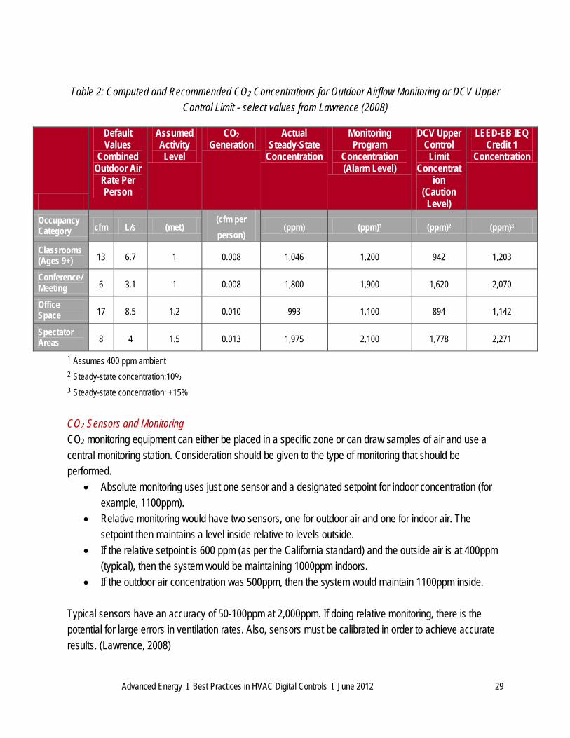
Table 2: Computed and Recommended CO2 Concentrations for Outdoor Airflow Monitoring or DCV Upper
Control Limit - select values from Lawrence (2008)
1 Assumes 400 ppm ambient 2 Steady-state concentration:10% 3 Steady-state concentration: +15% CO2 Sensors and Monitoring CO2 monitoring equipment can either be placed in a specific zone or can draw samples of air and use a central monitoring station. Consideration should be given to the type of monitoring that should be performed.
• Absolute monitoring uses just one sensor and a designated setpoint for indoor concentration (for example, 1100ppm).
• Relative monitoring would have two sensors, one for outdoor air and one for indoor air. The setpoint then maintains a level inside relative to levels outside.
• If the relative setpoint is 600 ppm (as per the California standard) and the outside air is at 400ppm (typical), then the system would be maintaining 1000ppm indoors.
• If the outdoor air concentration was 500ppm, then the system would maintain 1100ppm inside.
Typical sensors have an accuracy of 50-100ppm at 2,000ppm. If doing relative monitoring, there is the potential for large errors in ventilation rates. Also, sensors must be calibrated in order to achieve accurate results. (Lawrence, 2008)
Default Values
Combined Outdoor Air
Rate Per Person
Assumed Activity Level
CO2 Generation
Actual Steady-State
Concentration
Monitoring Program
Concentration (Alarm Level)
DCV Upper Control
Limit Concentrat
ion (Caution
Level)
LEED-EB IEQ Credit 1
Concentration
Occupancy Category cfm L/s (met)
(cfm per person)
(ppm) (ppm)1 (ppm)2 (ppm)3
Classrooms (Ages 9+) 13 6.7 1 0.008 1,046 1,200 942 1,203
Conference/ Meeting 6 3.1 1 0.008 1,800 1,900 1,620 2,070
Office Space 17 8.5 1.2 0.010 993 1,100 894 1,142
Spectator Areas 8 4 1.5 0.013 1,975 2,100 1,778 2,271
Advanced Energy I Best Practices in HVAC Digital Controls I June 2012 30
WORKS CITED State Energy Office of the North Carolina Department of Administration. (2010). Guidelines for HVAC Controls Tune-up Program - Utilitiy Savings Initiative. Raleigh, NC, USA. Butler, J. F. (2010). Point Naming Standards. ASHRAE Journal , B16-20. Churchill,Gregory, Oregon Office of Energy. (n.d.). The Direct Digital Control Crisis in Oregon Public Schools: Offering Solutions Through Trouble-Shooting Services. Georgia Power Company. (2010). Retrieved from Chiller Systems.: http://www.georgiapower.com/energy_knowhow/free_cooling.asp Haines, R. W. (2003). HVAC Systems Design Handbook. Hatton, M. A., Sullivan, T. P., & Newlands, L. (2010). Optimizing Building Controls During Commissioning. ASHRAE Journal , 22-27. HVAC Commissioning. (2011). Retrieved from Houston Commissioning - HVAC Commissioning: http://www.houstoncommissioning.com/hvac.htm Lawrence, T. M. (2008). Criteria for Outdoor Air Monitoring. ASHRAE Journal , 18-27. McGowan, J. J. (2003). Operating Online: A Real-Time System Integration Update. McQuiston, F. C. (2005). Heating, Ventilation, and Air Conditioning. Retrieved from Wikipedia: http://en.wikipedia.org/wiki/Free_cooling#Free_Cooling_in_HVAC Murphy, J. a. (May 2009). Using Time-of-Day Scheduling to Save Energy ASHRAE Journal. ASHRAE Journal , 42-48. Taylor, Steve (2010). Why Enthalpy Controls Don't Work. ASHRAE Journal.
Advanced Energy I Best Practices in HVAC Digital Controls I June 2012 31
RESOURCES Special thanks to the following individuals for their practical knowledge and valuable input: Charles Lamm - Nash Rocky Mount School System Scott Thompson - Wake County Public School System Ralph Everett - Wake County Public School System Bob Bittner - Wake County Public School System Peter Morgan – Educon Consulting Len Hoey – NC State Energy Office Pete Rojeski, P.E., PhD – Measurement and Verification Services Other resources consulted: ASHRAE Journal California Energy Commission California Commissioning Collaborative DDC Online www.ddc-online.org ENERGY STAR® Portland Energy Conservation Initiative
Recommended