III. Capteurs de température
IUT GC GP Capteur. Routoure 2010-2011
Résultat d’une recherche Farnell (distributeur)
2130 produits trouvés !!!
IUT GC GP Capteur. Routoure 2010-2011
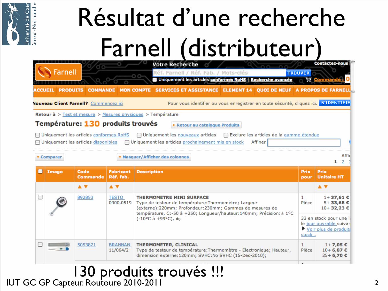
Résultat d’une recherche Radiospares (distributeur)
3
163 produits trouvés !!!
IUT GC GP Capteur. Routoure 2010-2011
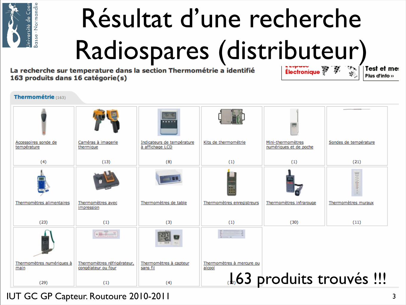
Capteur de température• 1. Echelle de température
• 1.bis : que mesure le thermomètre
• 2. Thermomètres à dilatation
• 2.1 de liquide
• 2.2 de gaz
• 3. Résistances métalliques
• 4. Thermistances
• 5 Thermocouples
• 6. Circuits intégrés : principe et quelques références
• 7. Pyromètres
• 8 Matrice de capteurs => vers les caméras
4
Capteur de températureI. Echelle de température
IUT GC GP Capteur. Routoure 2010-2011
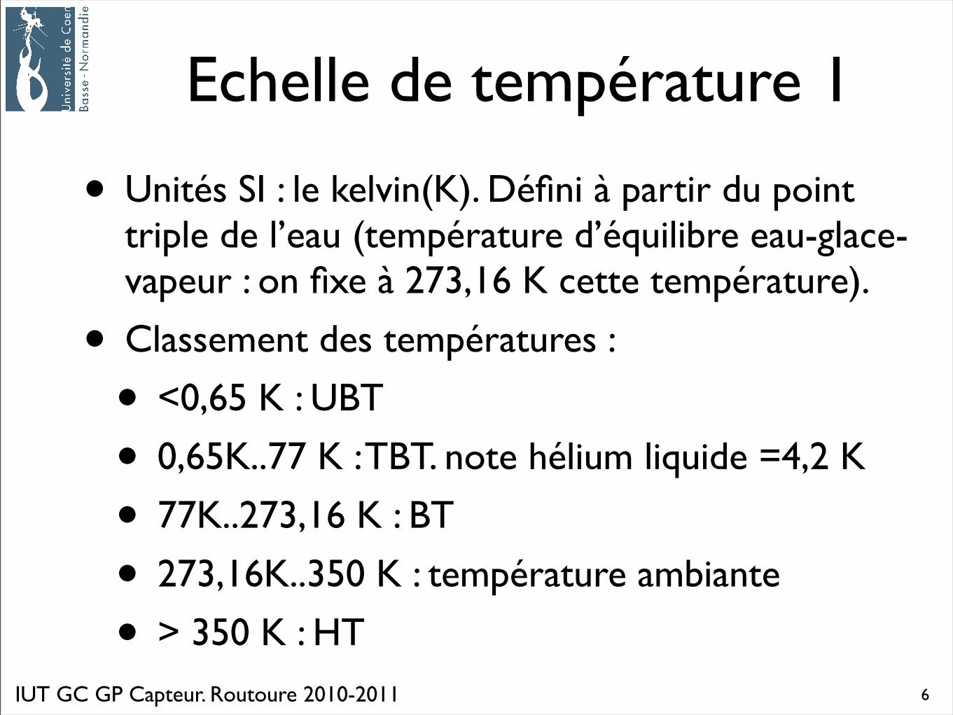
Echelle de température 1
• Unités SI : le kelvin(K). Défini à partir du point triple de l’eau (température d’équilibre eau-glace-vapeur : on fixe à 273,16 K cette température).
• Classement des températures :
• <0,65 K : UBT
• 0,65K..77 K : TBT. note hélium liquide =4,2 K
• 77K..273,16 K : BT
• 273,16K..350 K : température ambiante
• > 350 K : HT6
IUT GC GP Capteur. Routoure 2010-2011
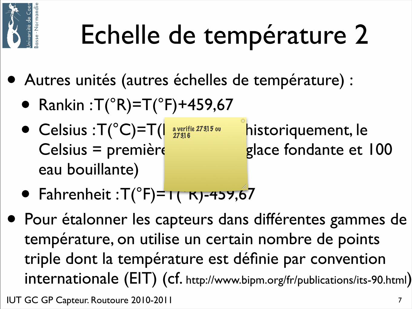
Echelle de température 2
• Autres unités (autres échelles de température) :
• Rankin : T(°R)=T(°F)+459,67
• Celsius : T(°C)=T(K)-273,15 ( historiquement, le Celsius = première echelle : 0 glace fondante et 100 eau bouillante)
• Fahrenheit : T(°F)=T(°R)-459,67
• Pour étalonner les capteurs dans différentes gammes de température, on utilise un certain nombre de points triple dont la température est définie par convention internationale (EIT) (cf. http://www.bipm.org/fr/publications/its-90.html)
7
a verifie 273,15 ou 273,16
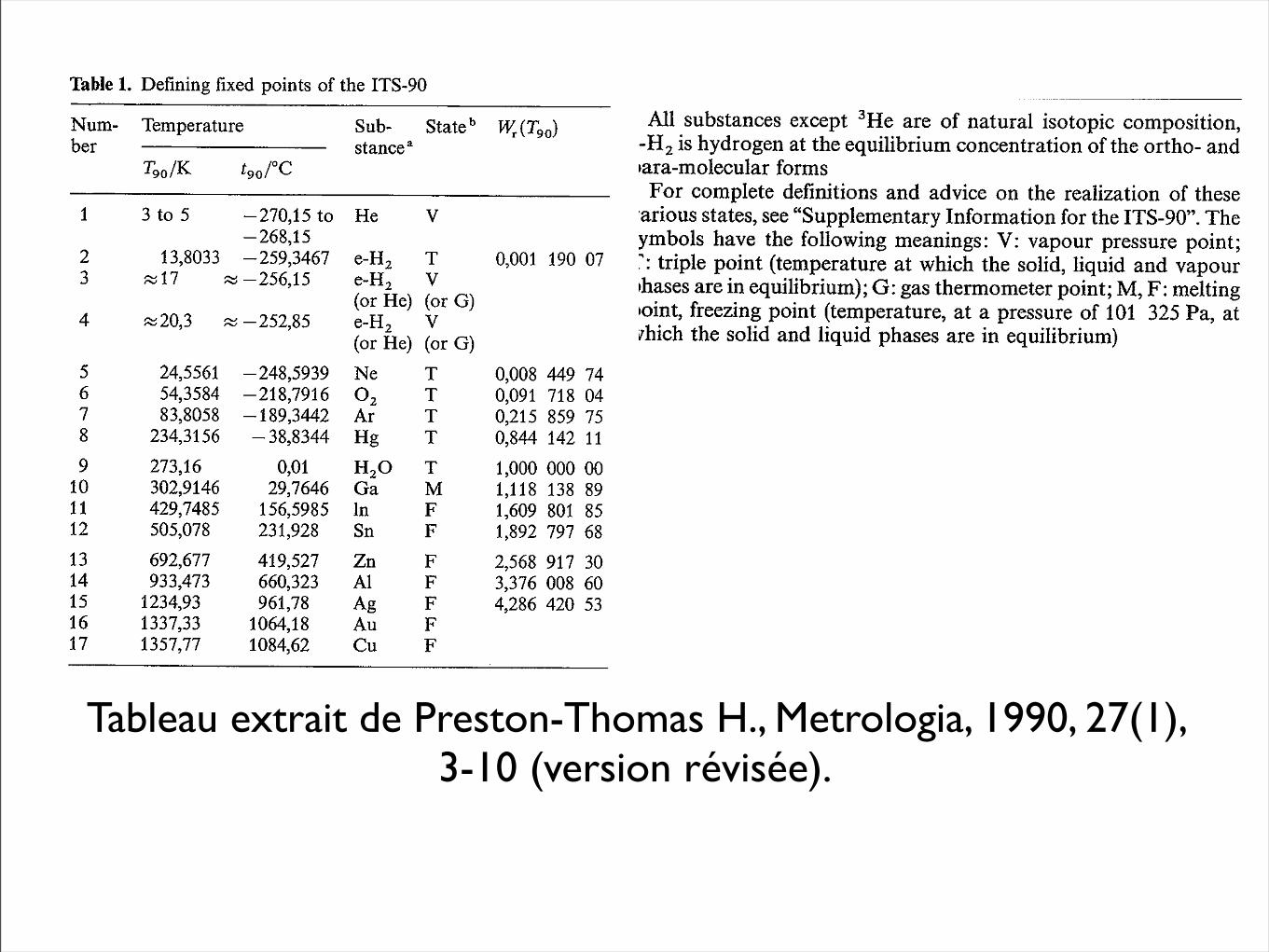
Tableau extrait de Preston-Thomas H., Metrologia, 1990, 27(1), 3-10 (version révisée).
Capteur de températureI.bis : que mesure le thermomètre :
traité en cours : pas de support vidéoprojeté


Capteur de température2. Thermomètres à dilatation
J.M. Routoure : cours capteur.
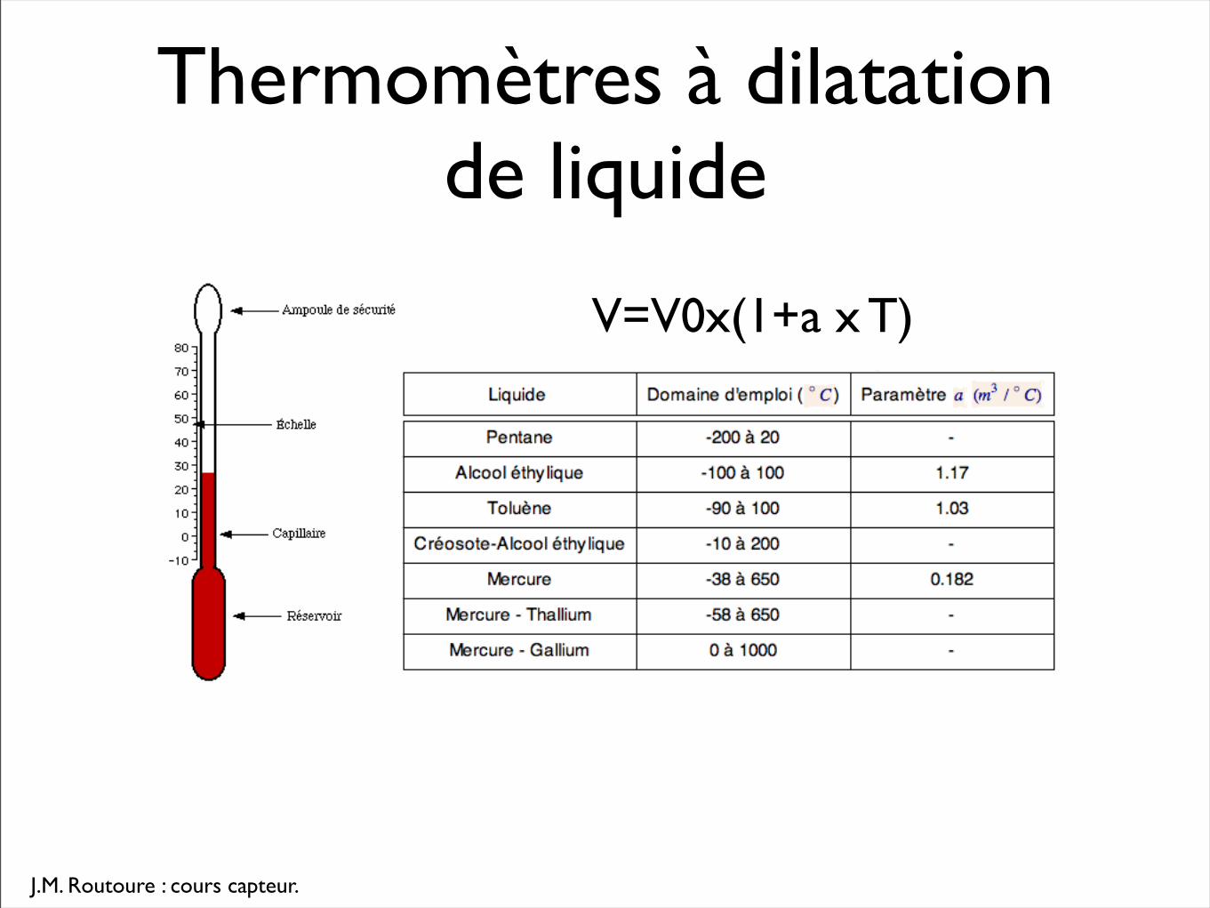
Thermomètres à dilatation de liquide
V=V0x(1+a x T)
J.M. Routoure : cours capteur.
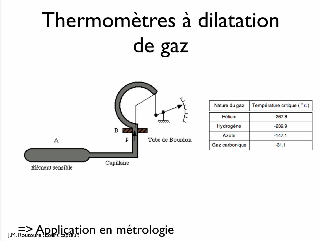
Thermomètres à dilatation de gaz
=> Application en métrologie
Capteur de température3. Résistances métalliques
IUT GC GP Capteur. Routoure 2010-2011
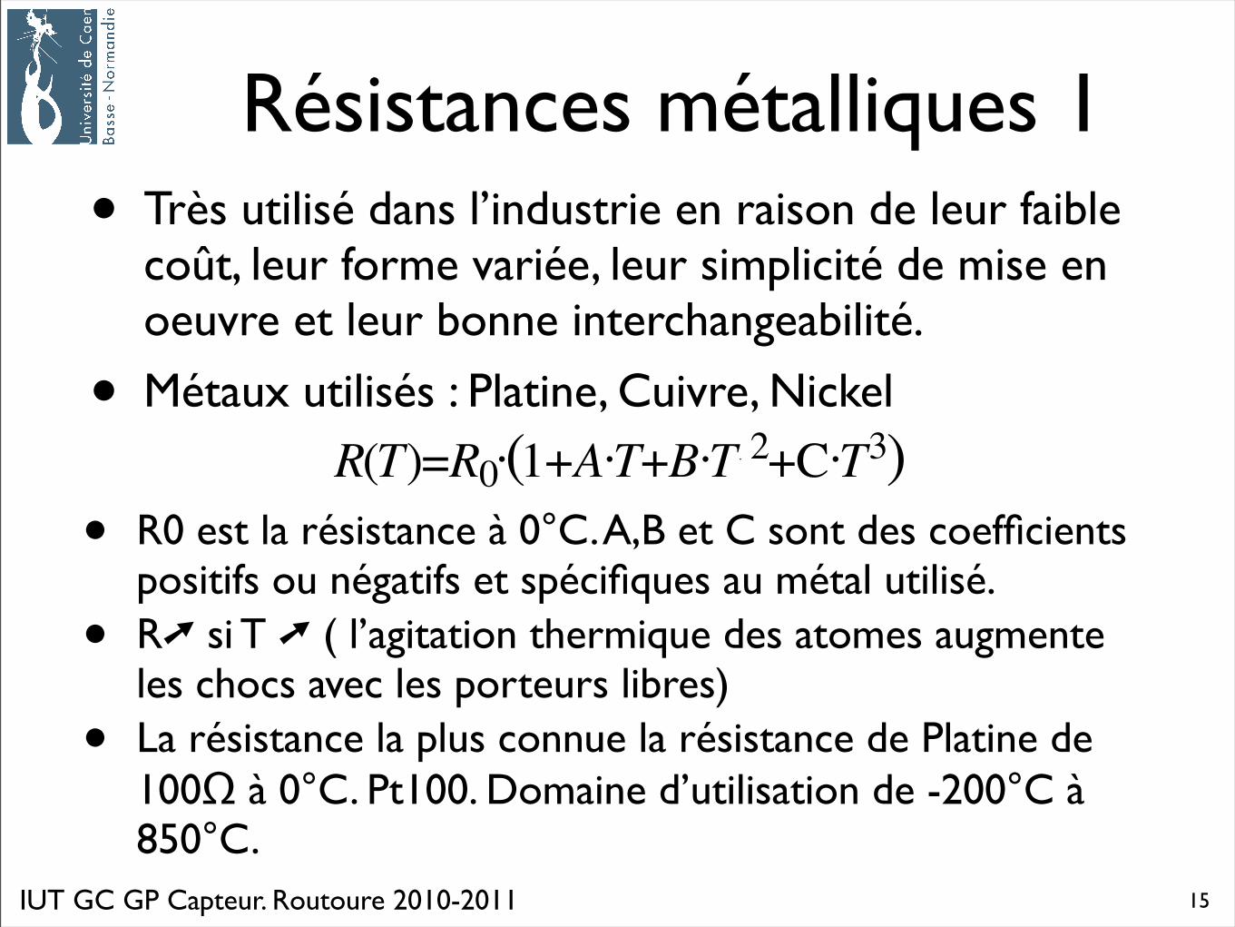
Résistances métalliques 1• Très utilisé dans l’industrie en raison de leur faible
coût, leur forme variée, leur simplicité de mise en oeuvre et leur bonne interchangeabilité.
• Métaux utilisés : Platine, Cuivre, Nickel
• R0 est la résistance à 0°C. A,B et C sont des coefficients positifs ou négatifs et spécifiques au métal utilisé.
• R➚ si T ➚ ( l’agitation thermique des atomes augmente les chocs avec les porteurs libres)
• La résistance la plus connue la résistance de Platine de 100Ω à 0°C. Pt100. Domaine d’utilisation de -200°C à 850°C.
15
IUT GC GP Capteur. Routoure 2010-2011
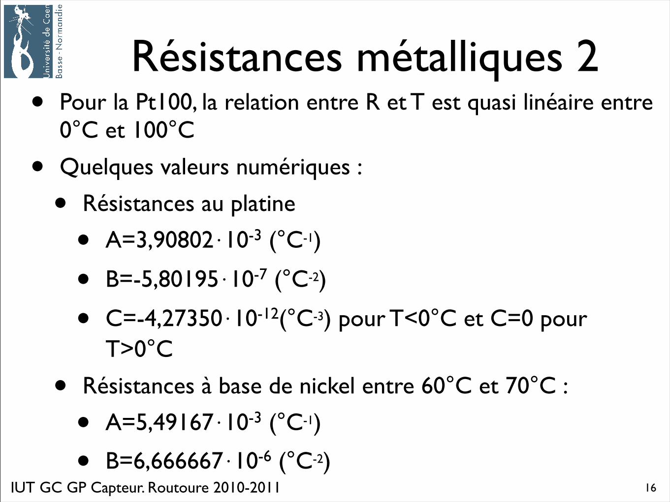
Résistances métalliques 2• Pour la Pt100, la relation entre R et T est quasi linéaire entre
0°C et 100°C
• Quelques valeurs numériques :
• Résistances au platine
• A=3,90802⋅10-3 (°C-1)
• B=-5,80195⋅10-7 (°C-2)
• C=-4,27350⋅10-12(°C-3) pour T<0°C et C=0 pour T>0°C
• Résistances à base de nickel entre 60°C et 70°C :
• A=5,49167⋅10-3 (°C-1)
• B=6,666667⋅10-6 (°C-2)16
IUT GC GP Capteur. Routoure 2010-2011
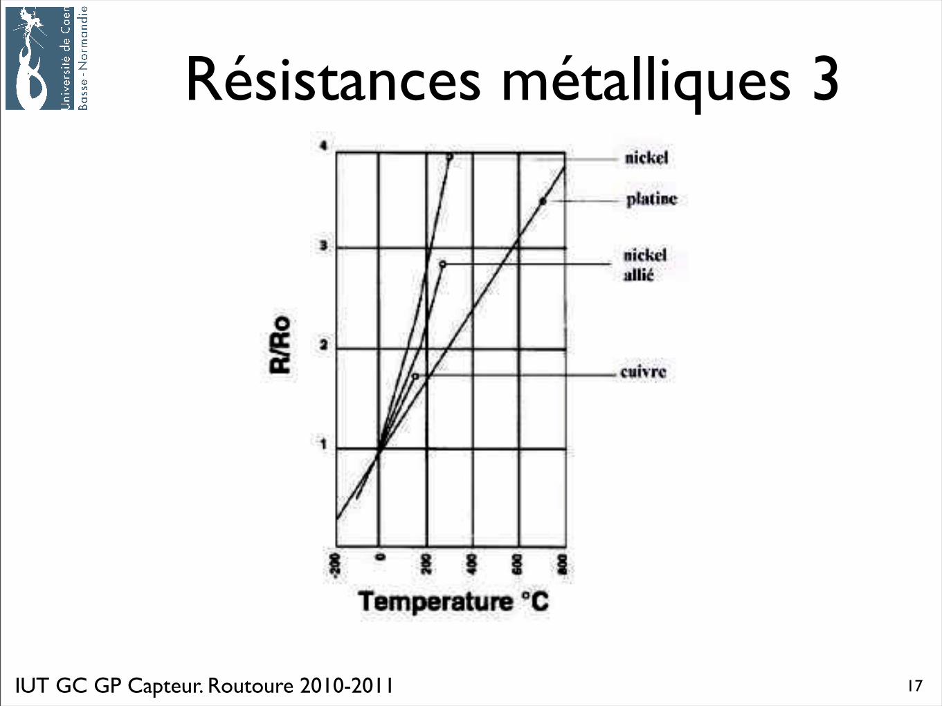
Résistances métalliques 3
17
IUT GC GP Capteur. Routoure 2010-2011
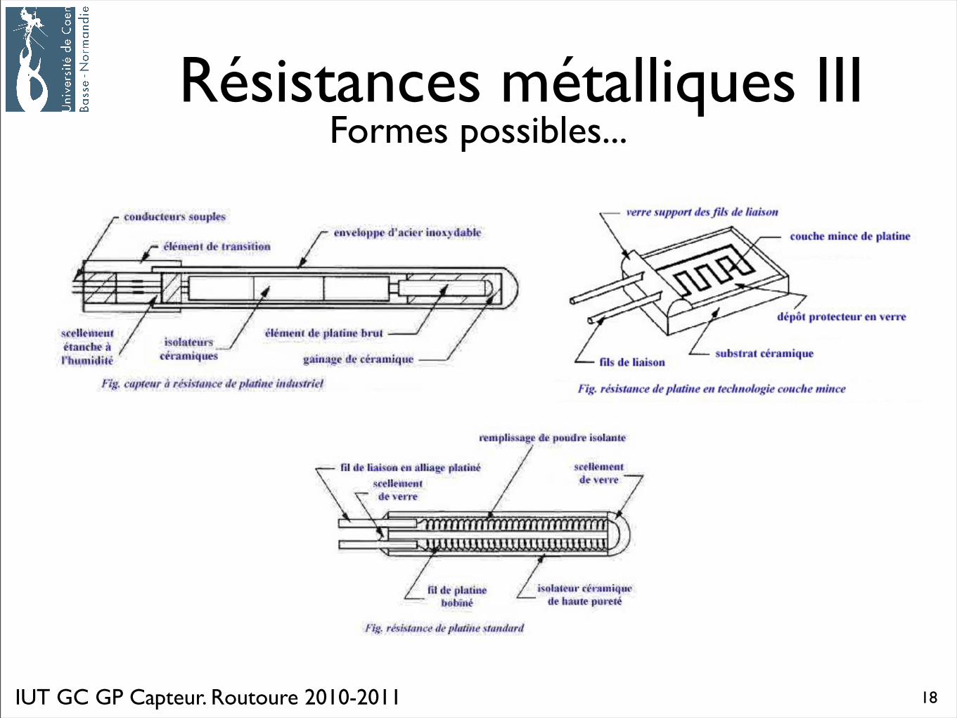
Résistances métalliques IIIFormes possibles...
18
IUT GC GP Capteur. Routoure 2010-2011
Quelques fiches capteurs
19
22/03/09 21:41PT100 sensors (Platinum Resistance Thermometers or RTD sensors)
Page 1 sur 2http://www.picotech.com/applications/pt100.html
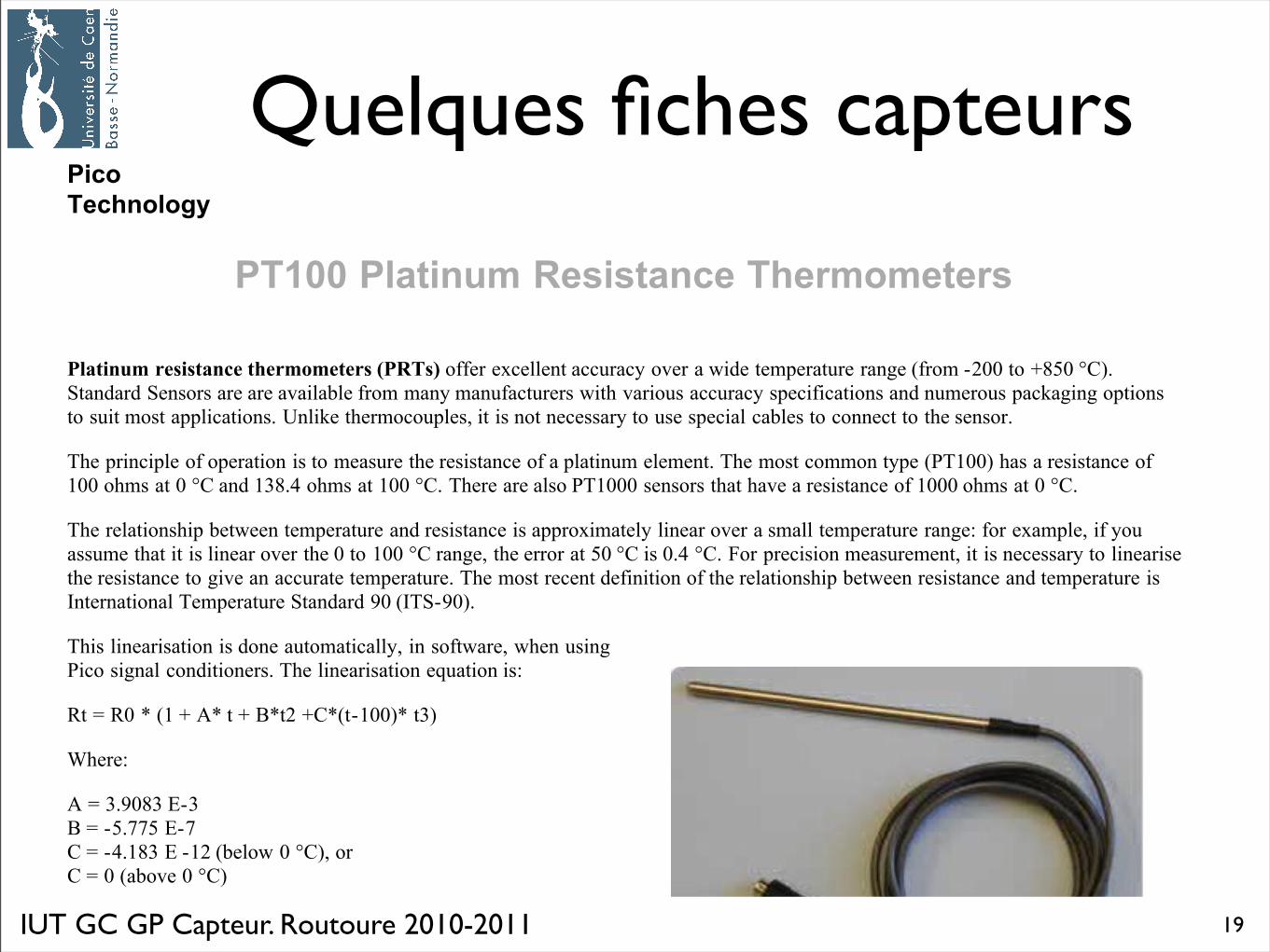
Platinum resistance thermometers (PRTs) offer excellent accuracy over a wide temperature range (from -200 to +850 °C).
Standard Sensors are are available from many manufacturers with various accuracy specifications and numerous packaging options
to suit most applications. Unlike thermocouples, it is not necessary to use special cables to connect to the sensor.
The principle of operation is to measure the resistance of a platinum element. The most common type (PT100) has a resistance of
100 ohms at 0 °C and 138.4 ohms at 100 °C. There are also PT1000 sensors that have a resistance of 1000 ohms at 0 °C.
The relationship between temperature and resistance is approximately linear over a small temperature range: for example, if you
assume that it is linear over the 0 to 100 °C range, the error at 50 °C is 0.4 °C. For precision measurement, it is necessary to linearise
the resistance to give an accurate temperature. The most recent definition of the relationship between resistance and temperature is
International Temperature Standard 90 (ITS-90).
This linearisation is done automatically, in software, when using
Pico signal conditioners. The linearisation equation is:
Rt = R0 * (1 + A* t + B*t2 +C*(t-100)* t3)
Where:
A = 3.9083 E-3
B = -5.775 E-7
C = -4.183 E -12 (below 0 °C), or
C = 0 (above 0 °C)
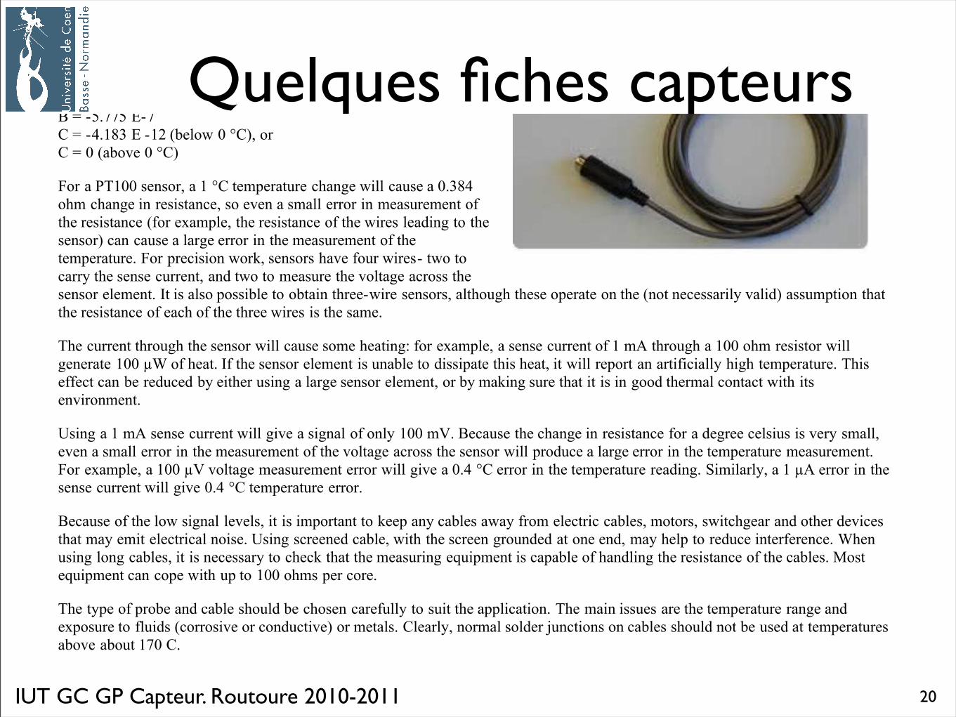
For a PT100 sensor, a 1 °C temperature change will cause a 0.384
ohm change in resistance, so even a small error in measurement of
the resistance (for example, the resistance of the wires leading to the
sensor) can cause a large error in the measurement of the
temperature. For precision work, sensors have four wires- two to
carry the sense current, and two to measure the voltage across the
sensor element. It is also possible to obtain three-wire sensors, although these operate on the (not necessarily valid) assumption that
the resistance of each of the three wires is the same.
The current through the sensor will cause some heating: for example, a sense current of 1 mA through a 100 ohm resistor will
generate 100 !W of heat. If the sensor element is unable to dissipate this heat, it will report an artificially high temperature. This
effect can be reduced by either using a large sensor element, or by making sure that it is in good thermal contact with its
environment.
Using a 1 mA sense current will give a signal of only 100 mV. Because the change in resistance for a degree celsius is very small,
even a small error in the measurement of the voltage across the sensor will produce a large error in the temperature measurement.
For example, a 100 !V voltage measurement error will give a 0.4 °C error in the temperature reading. Similarly, a 1 !A error in the
sense current will give 0.4 °C temperature error.
Because of the low signal levels, it is important to keep any cables away from electric cables, motors, switchgear and other devices
that may emit electrical noise. Using screened cable, with the screen grounded at one end, may help to reduce interference. When
using long cables, it is necessary to check that the measuring equipment is capable of handling the resistance of the cables. Most
equipment can cope with up to 100 ohms per core.
The type of probe and cable should be chosen carefully to suit the application. The main issues are the temperature range and
exposure to fluids (corrosive or conductive) or metals. Clearly, normal solder junctions on cables should not be used at temperatures
above about 170 C.
Pico
Technology
PT100 Platinum Resistance Thermometers
IUT GC GP Capteur. Routoure 2010-2011
Quelques fiches capteurs
20
22/03/09 21:41PT100 sensors (Platinum Resistance Thermometers or RTD sensors)
Page 1 sur 2http://www.picotech.com/applications/pt100.html
Platinum resistance thermometers (PRTs) offer excellent accuracy over a wide temperature range (from -200 to +850 °C).
Standard Sensors are are available from many manufacturers with various accuracy specifications and numerous packaging options
to suit most applications. Unlike thermocouples, it is not necessary to use special cables to connect to the sensor.
The principle of operation is to measure the resistance of a platinum element. The most common type (PT100) has a resistance of
100 ohms at 0 °C and 138.4 ohms at 100 °C. There are also PT1000 sensors that have a resistance of 1000 ohms at 0 °C.
The relationship between temperature and resistance is approximately linear over a small temperature range: for example, if you
assume that it is linear over the 0 to 100 °C range, the error at 50 °C is 0.4 °C. For precision measurement, it is necessary to linearise
the resistance to give an accurate temperature. The most recent definition of the relationship between resistance and temperature is
International Temperature Standard 90 (ITS-90).
This linearisation is done automatically, in software, when using
Pico signal conditioners. The linearisation equation is:
Rt = R0 * (1 + A* t + B*t2 +C*(t-100)* t3)
Where:
A = 3.9083 E-3
B = -5.775 E-7
C = -4.183 E -12 (below 0 °C), or
C = 0 (above 0 °C)
For a PT100 sensor, a 1 °C temperature change will cause a 0.384
ohm change in resistance, so even a small error in measurement of
the resistance (for example, the resistance of the wires leading to the
sensor) can cause a large error in the measurement of the
temperature. For precision work, sensors have four wires- two to
carry the sense current, and two to measure the voltage across the
sensor element. It is also possible to obtain three-wire sensors, although these operate on the (not necessarily valid) assumption that
the resistance of each of the three wires is the same.
The current through the sensor will cause some heating: for example, a sense current of 1 mA through a 100 ohm resistor will
generate 100 !W of heat. If the sensor element is unable to dissipate this heat, it will report an artificially high temperature. This
effect can be reduced by either using a large sensor element, or by making sure that it is in good thermal contact with its
environment.
Using a 1 mA sense current will give a signal of only 100 mV. Because the change in resistance for a degree celsius is very small,
even a small error in the measurement of the voltage across the sensor will produce a large error in the temperature measurement.
For example, a 100 !V voltage measurement error will give a 0.4 °C error in the temperature reading. Similarly, a 1 !A error in the
sense current will give 0.4 °C temperature error.
Because of the low signal levels, it is important to keep any cables away from electric cables, motors, switchgear and other devices
that may emit electrical noise. Using screened cable, with the screen grounded at one end, may help to reduce interference. When
using long cables, it is necessary to check that the measuring equipment is capable of handling the resistance of the cables. Most
equipment can cope with up to 100 ohms per core.
The type of probe and cable should be chosen carefully to suit the application. The main issues are the temperature range and
exposure to fluids (corrosive or conductive) or metals. Clearly, normal solder junctions on cables should not be used at temperatures
above about 170 C.
Pico
Technology
PT100 Platinum Resistance Thermometers
IUT GC GP Capteur. Routoure 2010-2011
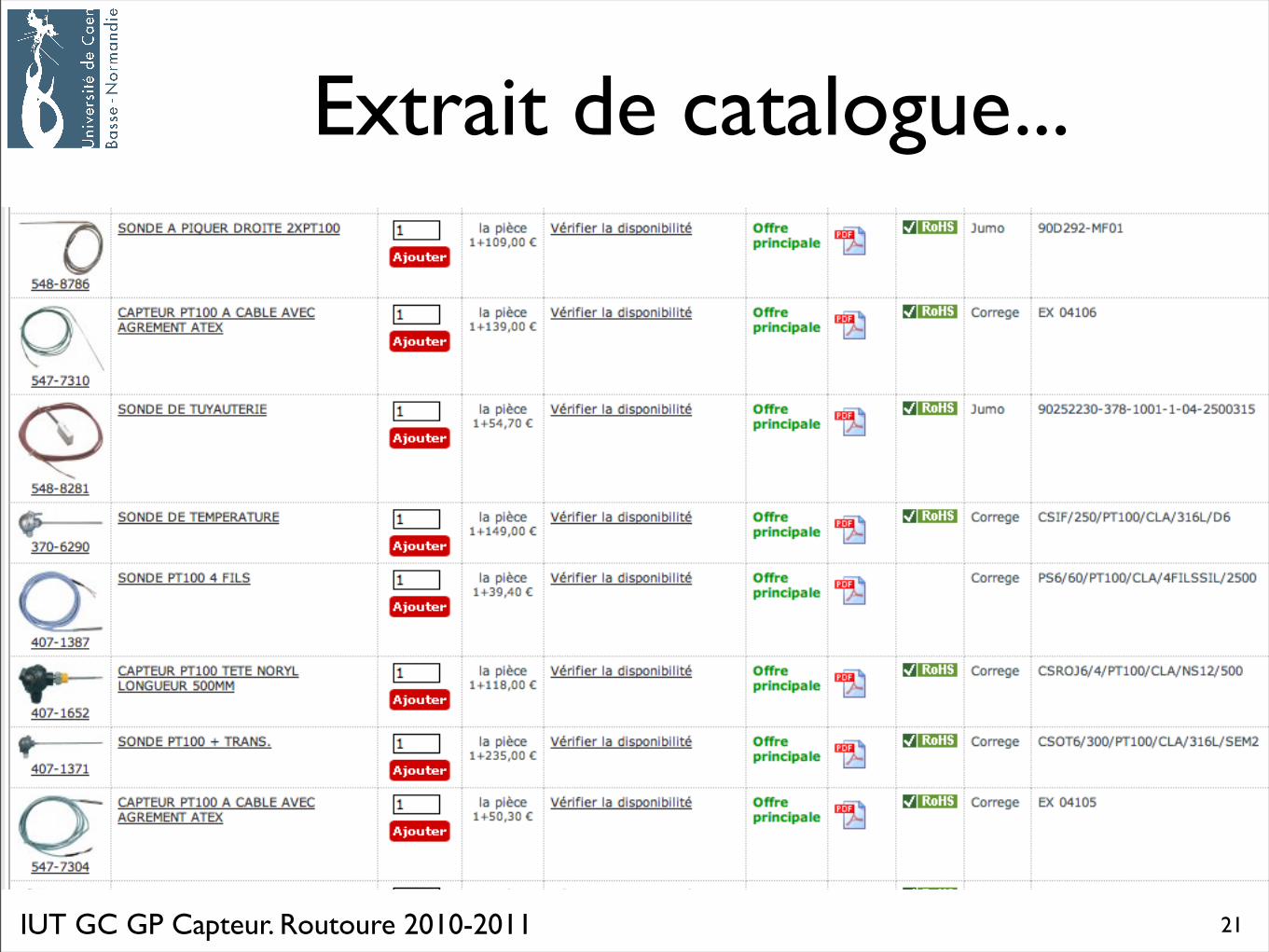
Extrait de catalogue...
21
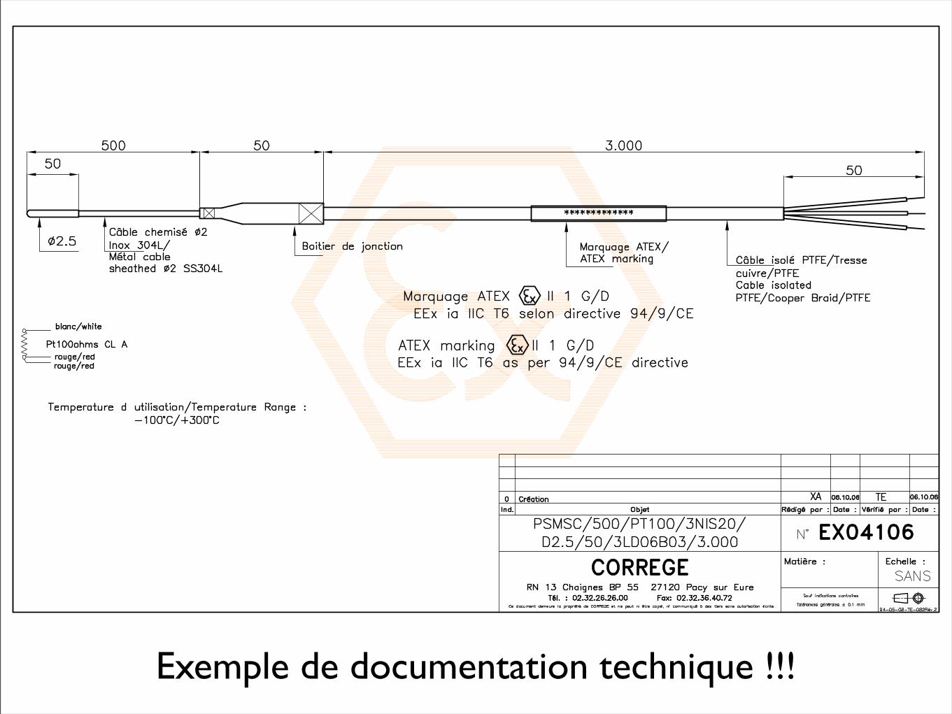
Exemple de documentation technique !!!
Capteur de température4. Thermistances
IUT GC GP Capteur. Routoure 2010-2011
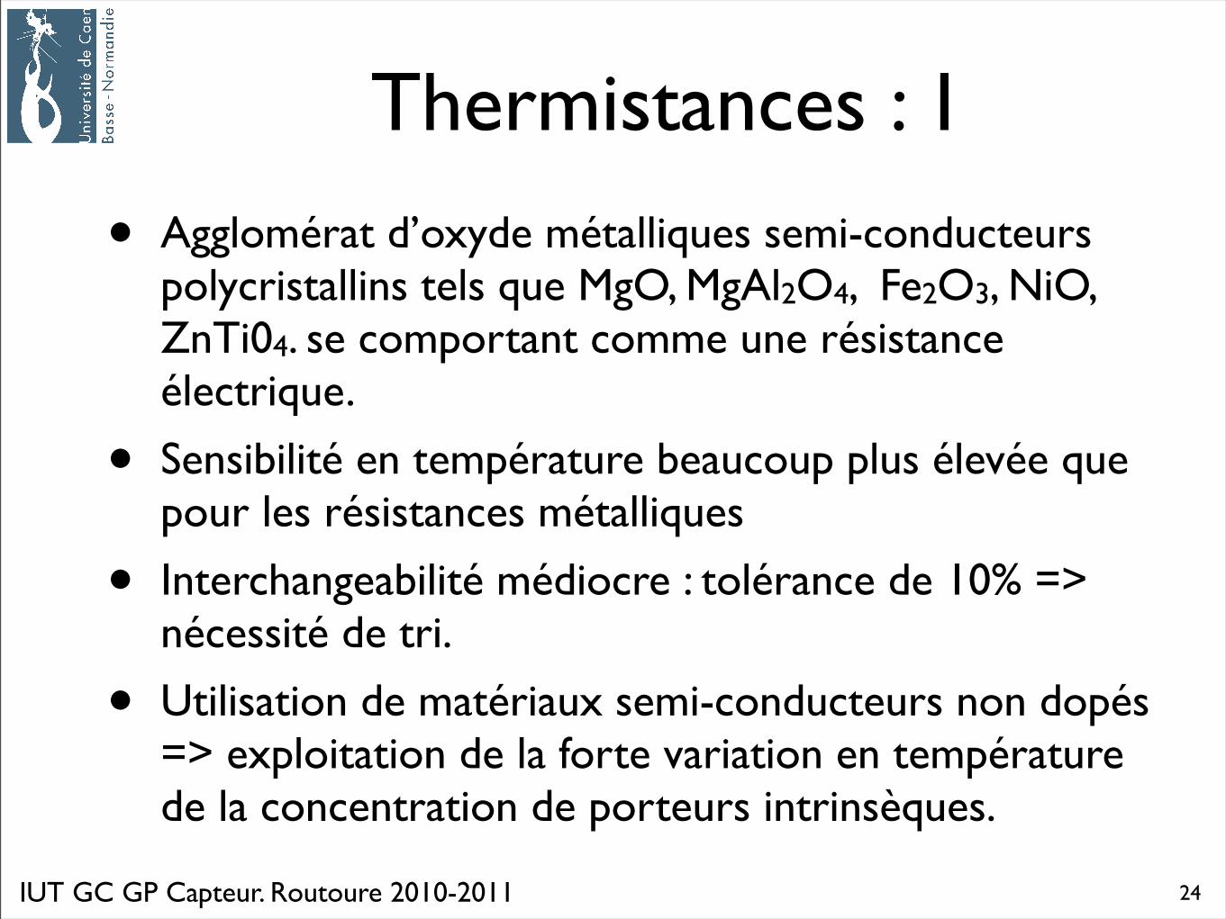
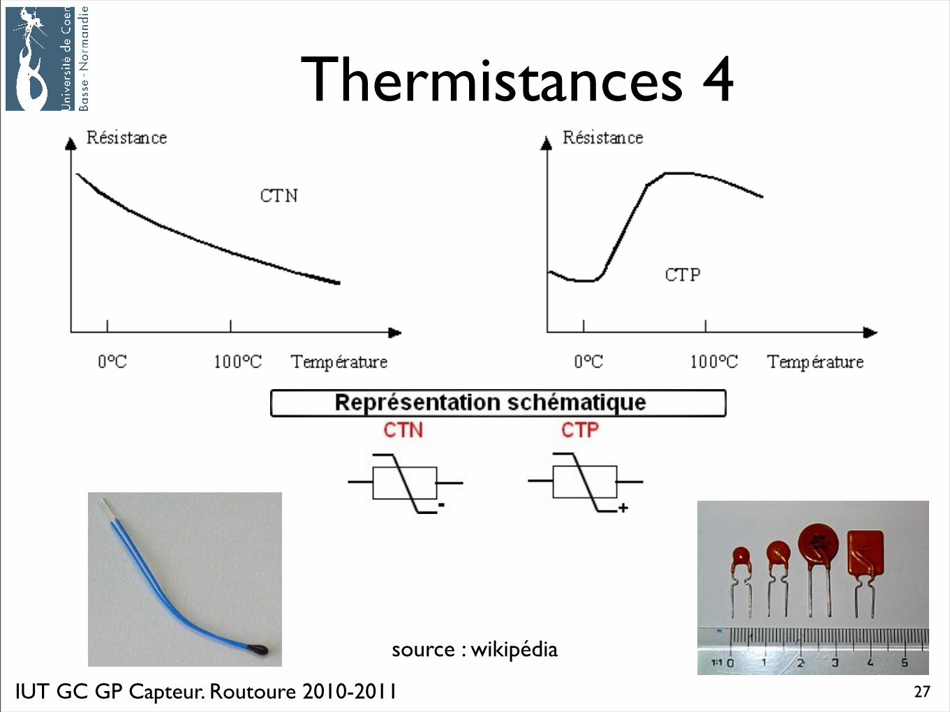
Thermistances : 1
• Agglomérat d’oxyde métalliques semi-conducteurs polycristallins tels que MgO, MgAl2O4, Fe2O3, NiO, ZnTi04. se comportant comme une résistance électrique.
• Sensibilité en température beaucoup plus élevée que pour les résistances métalliques
• Interchangeabilité médiocre : tolérance de 10% => nécessité de tri.
• Utilisation de matériaux semi-conducteurs non dopés => exploitation de la forte variation en température de la concentration de porteurs intrinsèques.
24
IUT GC GP Capteur. Routoure 2010-2011
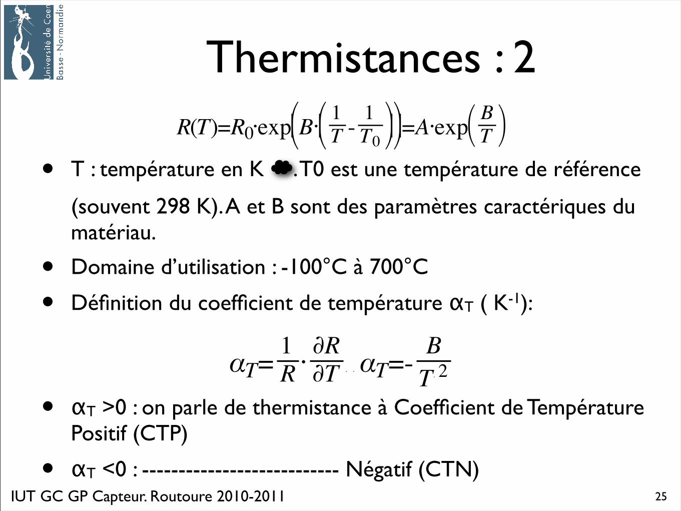
Thermistances : 2
• T : température en K ☁. T0 est une température de référence
(souvent 298 K). A et B sont des paramètres caractériques du matériau.
• Domaine d’utilisation : -100°C à 700°C
• Définition du coefficient de température αT ( K-1):
• αT >0 : on parle de thermistance à Coefficient de Température Positif (CTP)
• αT <0 : --------------------------- Négatif (CTN)25
IUT GC GP Capteur. Routoure 2010-2011
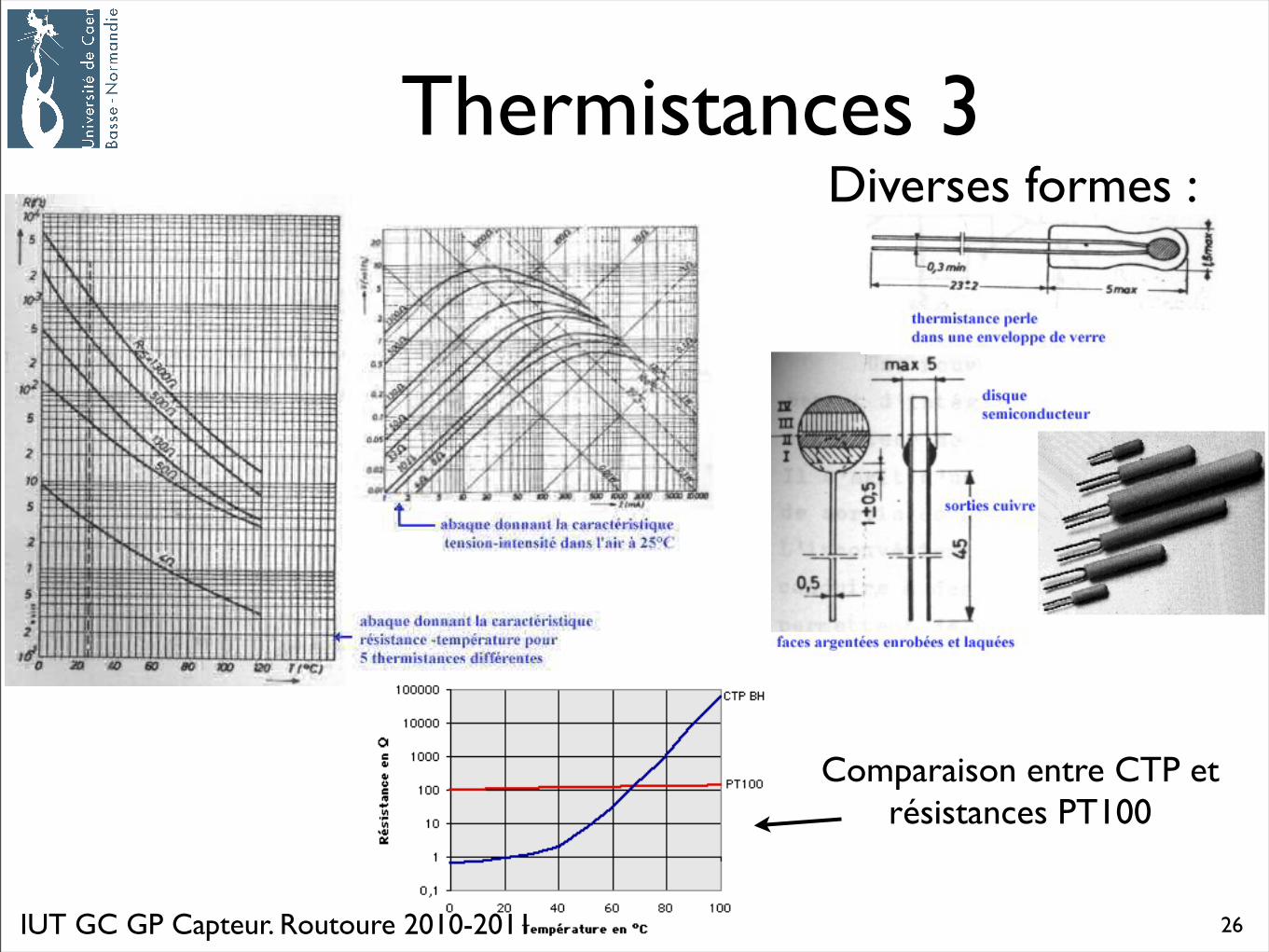
Thermistances 3Diverses formes :
Comparaison entre CTP et résistances PT100
26
IUT GC GP Capteur. Routoure 2010-2011
Thermistances 4
source : wikipédia
27
IUT GC GP Capteur. Routoure 2010-2011
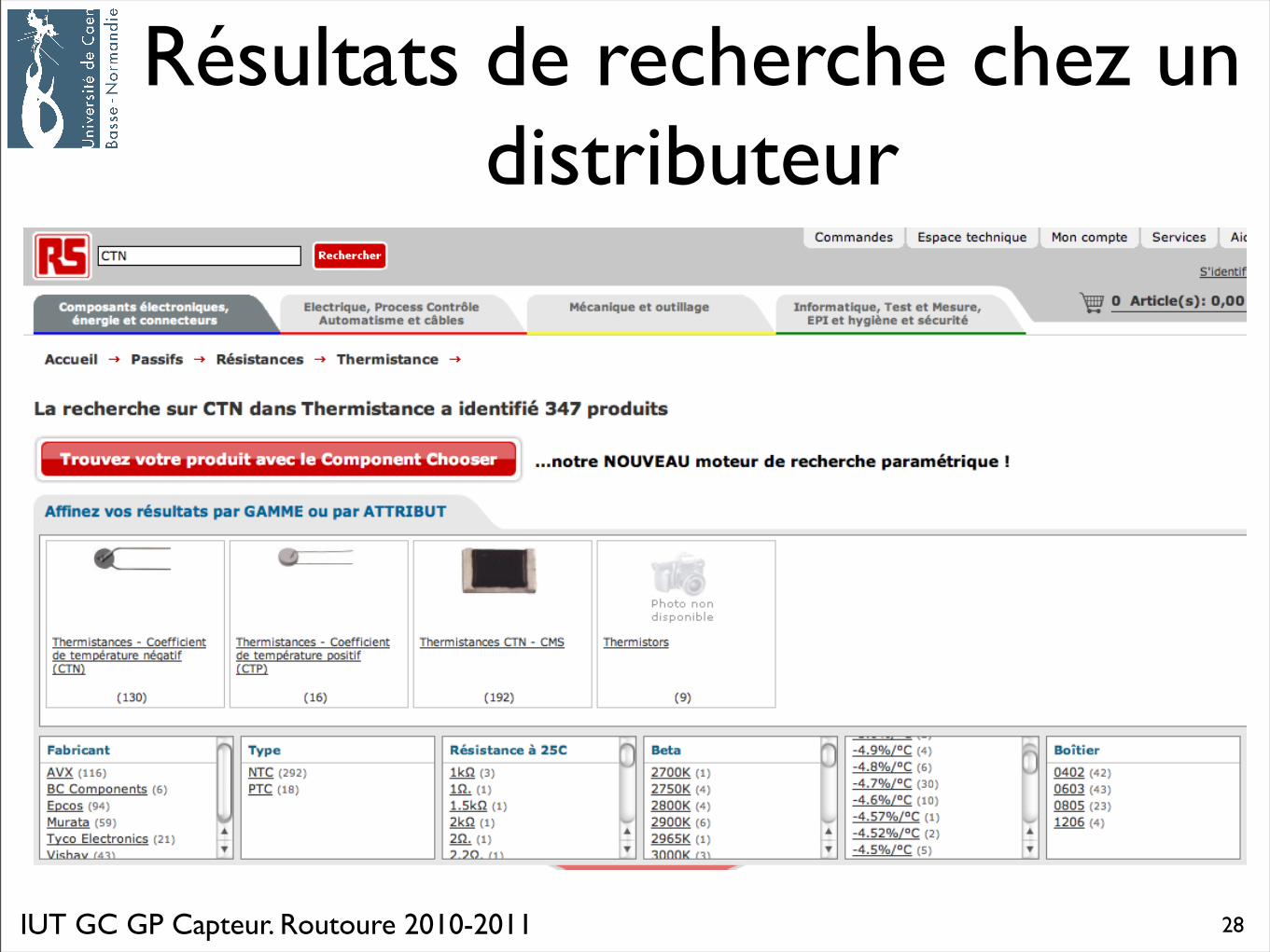
Résultats de recherche chez un distributeur
28
IUT GC GP Capteur. Routoure 2010-2011
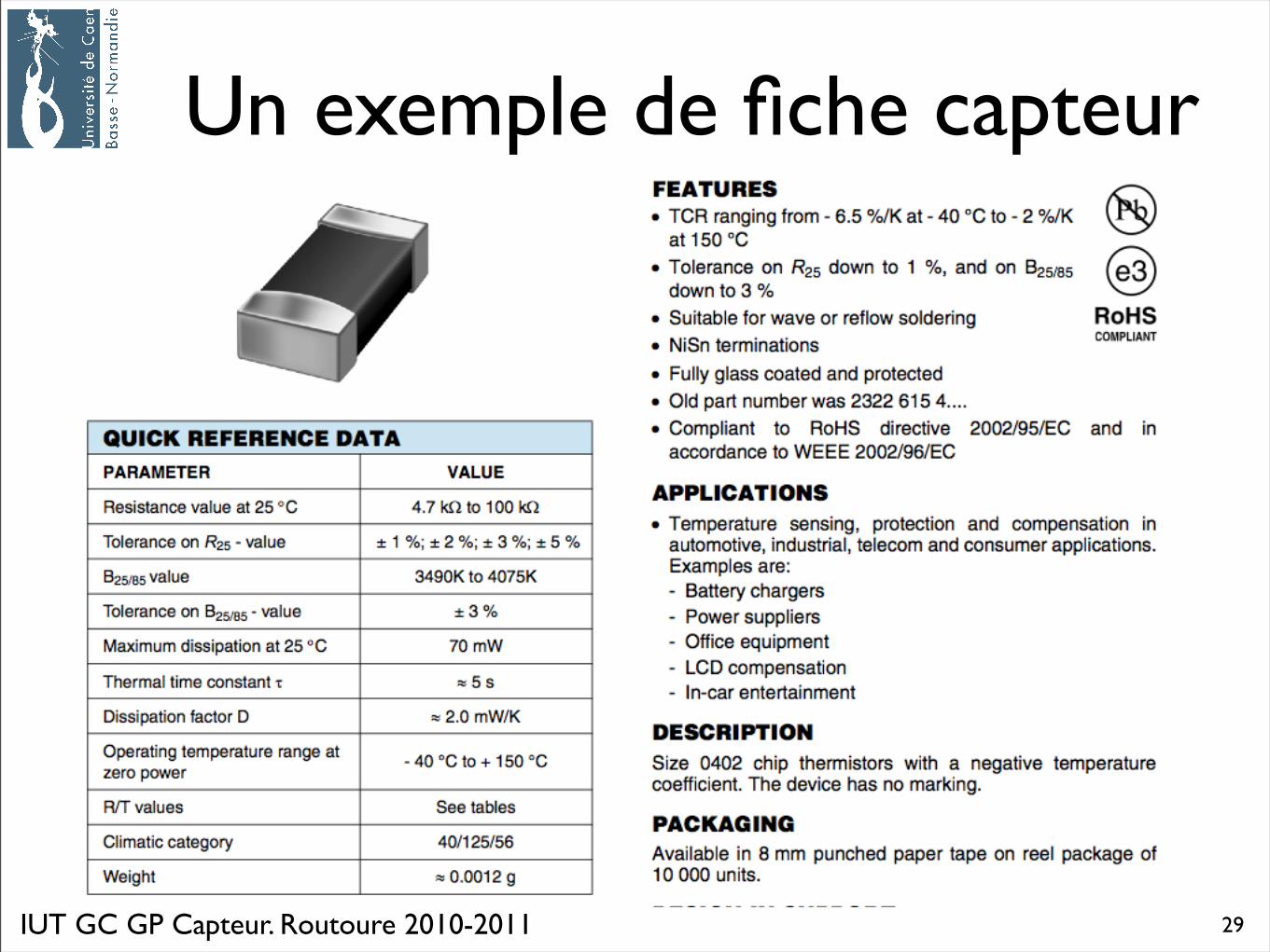
Un exemple de fiche capteur
29
Capteur de température5. Thermocouples
IUT GC GP Capteur. Routoure 2010-2011
Thermocouple 1
• Exploitation de l’effet Peltier et de l’effet Thompson.
• Effet Peltier : à la jonction( soudure ) de deux conducteurs A et B différents s’établit une différence de potentiel qui ne dépend que de la température et de la nature des conducteurs.
• Effet Thompson : Entre deux points M et N à température différente à l’intérieur d’un conducteur homogène A s’établit une force électromotrice ne dépendant que de la nature du conducteur et des températures entre M et N.
31
IUT GC GP Capteur. Routoure 2010-2011
Thermocouple 2
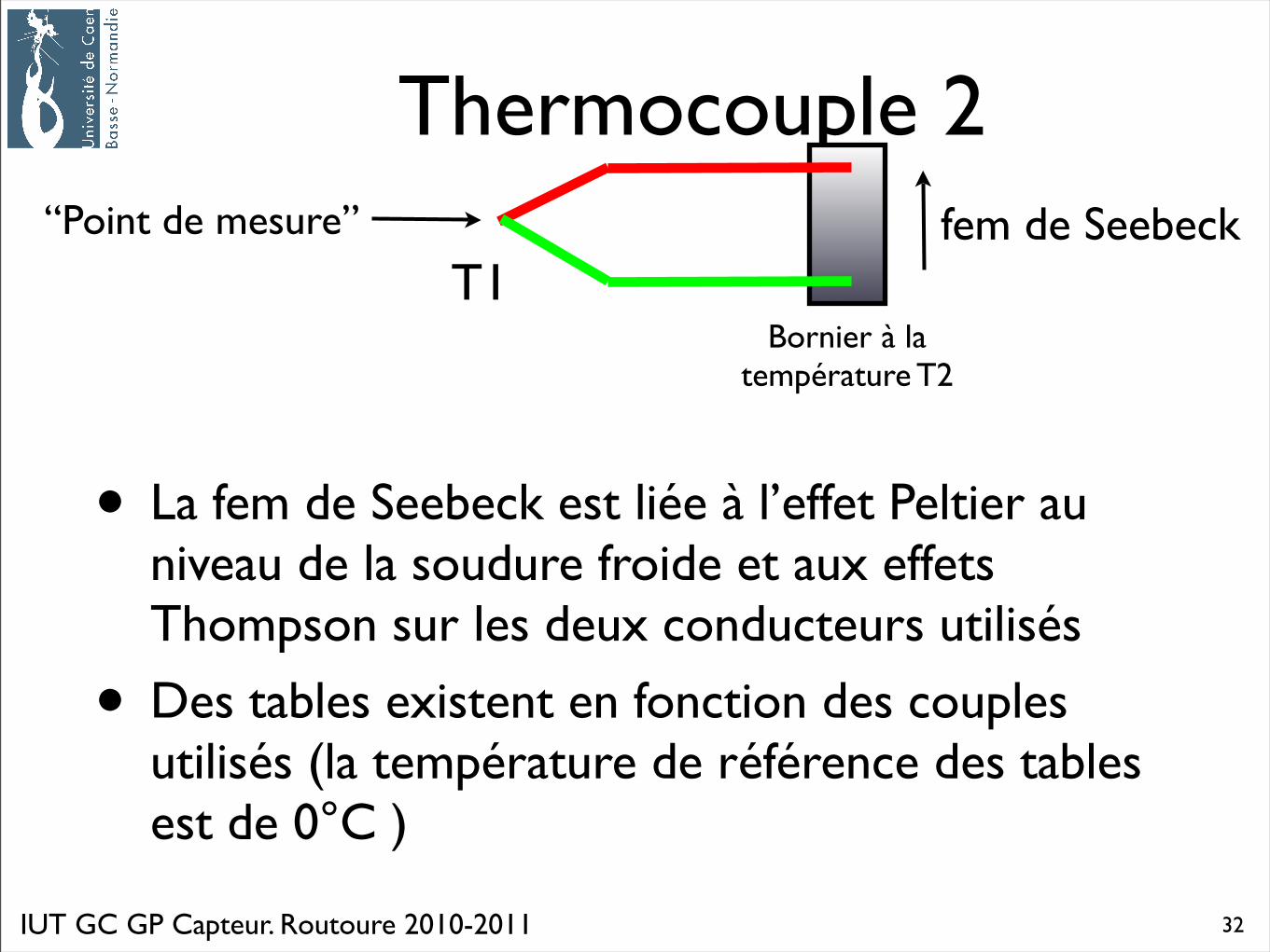
• La fem de Seebeck est liée à l’effet Peltier au niveau de la soudure froide et aux effets Thompson sur les deux conducteurs utilisés
• Des tables existent en fonction des couples utilisés (la température de référence des tables est de 0°C )
T1Bornier à la
température T2
“Point de mesure” fem de Seebeck
32
IUT GC GP Capteur. Routoure 2010-2011
Thermocouples 3• Intérêts :
• élément sensible de très petite taille
• capteur actif : pas d’autoéchauffement lié à la circulation de courant pour la lecture de la valeur de la résistance
• grande gamme d’utilisation
• Inconvénients :
• Pas d’évolution linéaire avec la température
• Nécessité d’utiliser des tables pour chaque couple utilisé
• Sensibilité médiocre (de l’ordre du μV/°C)
33
IUT GC GP Capteur. Routoure 2010-2011
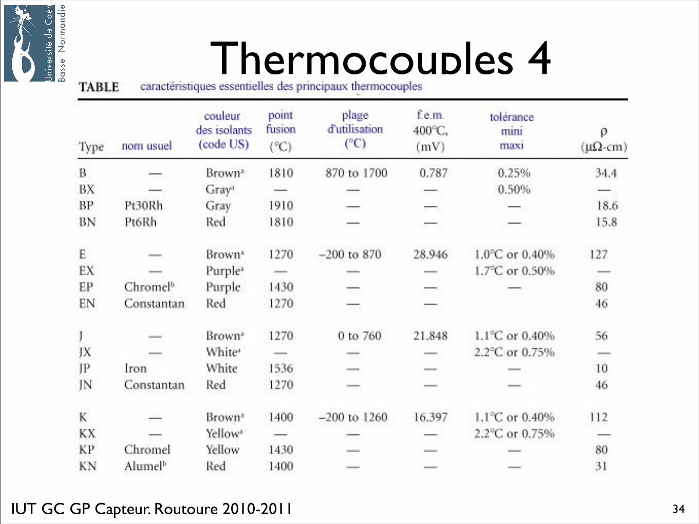
Thermocouples 4
34
IUT GC GP Capteur. Routoure 2010-2011
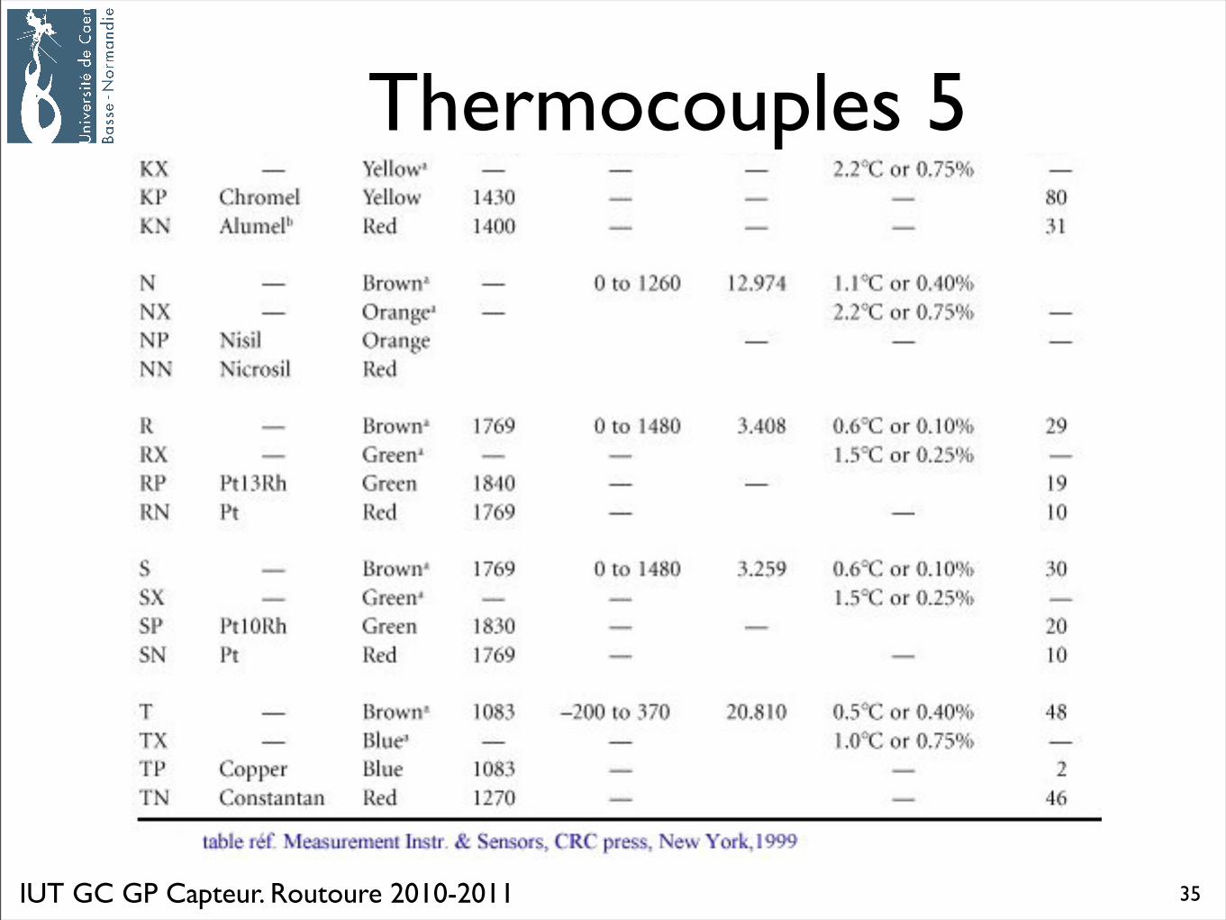
Thermocouples 5
35
IUT GC GP Capteur. Routoure 2010-2011
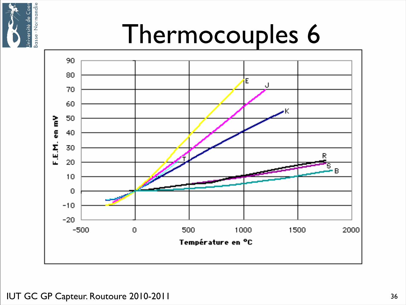
Thermocouples 6
36
IUT GC GP Capteur. Routoure 2010-2011
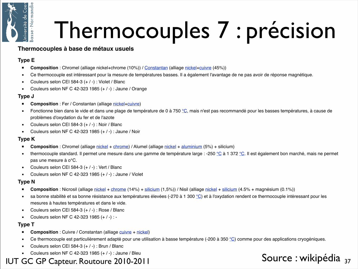
Thermocouples 7 : précisionThermocouples à base de métaux usuels
Type E ! ▪! Composition : Chromel (alliage nickel+chrome (10%)) / Constantan (alliage nickel+cuivre (45%))" ▪" Ce thermocouple est intéressant pour la mesure de températures basses. Il a également l'avantage de ne pas avoir de réponse magnétique." ▪" Couleurs selon CEI 584-3 (+ / -) : Violet / Blanc" ▪" Couleurs selon NF C 42-323 1985 (+ / -) : Jaune / OrangeType J ! ▪! Composition : Fer / Constantan (alliage nickel+cuivre)" ▪" Fonctionne bien dans le vide et dans une plage de température de 0 à 750 °C, mais n'est pas recommandé pour les basses températures, à cause de
problèmes d'oxydation du fer et de l'azote" ▪" Couleurs selon CEI 584-3 (+ / -) : Noir / Blanc" ▪" Couleurs selon NF C 42-323 1985 (+ / -) : Jaune / NoirType K ! ▪! Composition : Chromel (alliage nickel + chrome) / Alumel (alliage nickel + aluminium (5%) + silicium)" ▪" thermocouple standard. Il permet une mesure dans une gamme de température large : -250 °C à 1 372 °C. Il est également bon marché, mais ne permet
pas une mesure à o°C." ▪" Couleurs selon CEI 584-3 (+ / -) : Vert / Blanc" ▪" Couleurs selon NF C 42-323 1985 (+ / -) : Jaune / VioletType N ! ▪! Composition : Nicrosil (alliage nickel + chrome (14%) + silicium (1,5%)) / Nisil (alliage nickel + silicium (4.5% + magnésium (0.1%))" ▪" sa bonne stabilité et sa bonne résistance aux températures élevées (-270 à 1 300 °C) et à l'oxydation rendent ce thermocouple intéressant pour les
mesures à hautes températures et dans le vide." ▪" Couleurs selon CEI 584-3 (+ / -) : Rose / Blanc" ▪" Couleurs selon NF C 42-323 1985 (+ / -) : -Type T ! ▪! Composition : Cuivre / Constantan (alliage cuivre + nickel)" ▪" Ce thermocouple est particulièrement adapté pour une utilisation à basse température (-200 à 350 °C) comme pour des applications cryogéniques." ▪" Couleurs selon CEI 584-3 (+ / -) : Brun / Blanc" ▪" Couleurs selon NF C 42-323 1985 (+ / -) : Jaune / Bleu
Source : wikipédia 37
IUT GC GP Capteur. Routoure 2010-2011
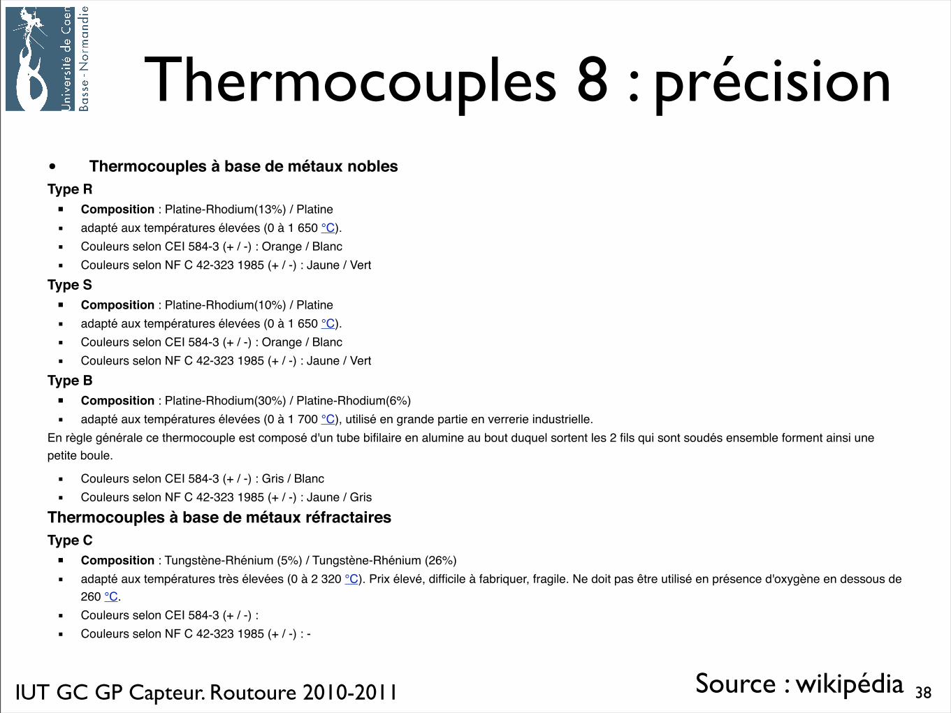
Thermocouples 8 : précision
Source : wikipédia
• Thermocouples à base de métaux nobles Type R ! ▪! Composition : Platine-Rhodium(13%) / Platine" ▪" adapté aux températures élevées (0 à 1 650 °C)." ▪" Couleurs selon CEI 584-3 (+ / -) : Orange / Blanc" ▪" Couleurs selon NF C 42-323 1985 (+ / -) : Jaune / VertType S ! ▪! Composition : Platine-Rhodium(10%) / Platine" ▪" adapté aux températures élevées (0 à 1 650 °C)." ▪" Couleurs selon CEI 584-3 (+ / -) : Orange / Blanc" ▪" Couleurs selon NF C 42-323 1985 (+ / -) : Jaune / VertType B ! ▪! Composition : Platine-Rhodium(30%) / Platine-Rhodium(6%)" ▪" adapté aux températures élevées (0 à 1 700 °C), utilisé en grande partie en verrerie industrielle.En règle générale ce thermocouple est composé d'un tube bifilaire en alumine au bout duquel sortent les 2 fils qui sont soudés ensemble forment ainsi une petite boule.
" ▪" Couleurs selon CEI 584-3 (+ / -) : Gris / Blanc" ▪" Couleurs selon NF C 42-323 1985 (+ / -) : Jaune / GrisThermocouples à base de métaux réfractaires Type C ! ▪! Composition : Tungstène-Rhénium (5%) / Tungstène-Rhénium (26%)" ▪" adapté aux températures très élevées (0 à 2 320 °C). Prix élevé, difficile à fabriquer, fragile. Ne doit pas être utilisé en présence d'oxygène en dessous de
260 °C." ▪" Couleurs selon CEI 584-3 (+ / -) :" ▪" Couleurs selon NF C 42-323 1985 (+ / -) : -
38
IUT GC GP Capteur. Routoure 2010-2011
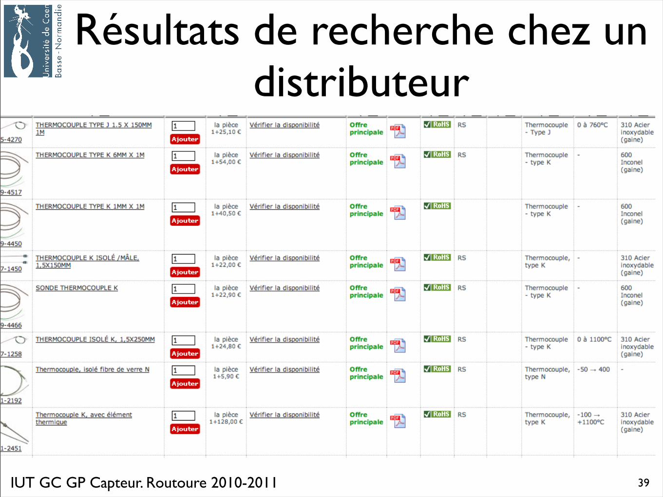
Résultats de recherche chez un distributeur
39
IUT GC GP Capteur. Routoure 2010-2011
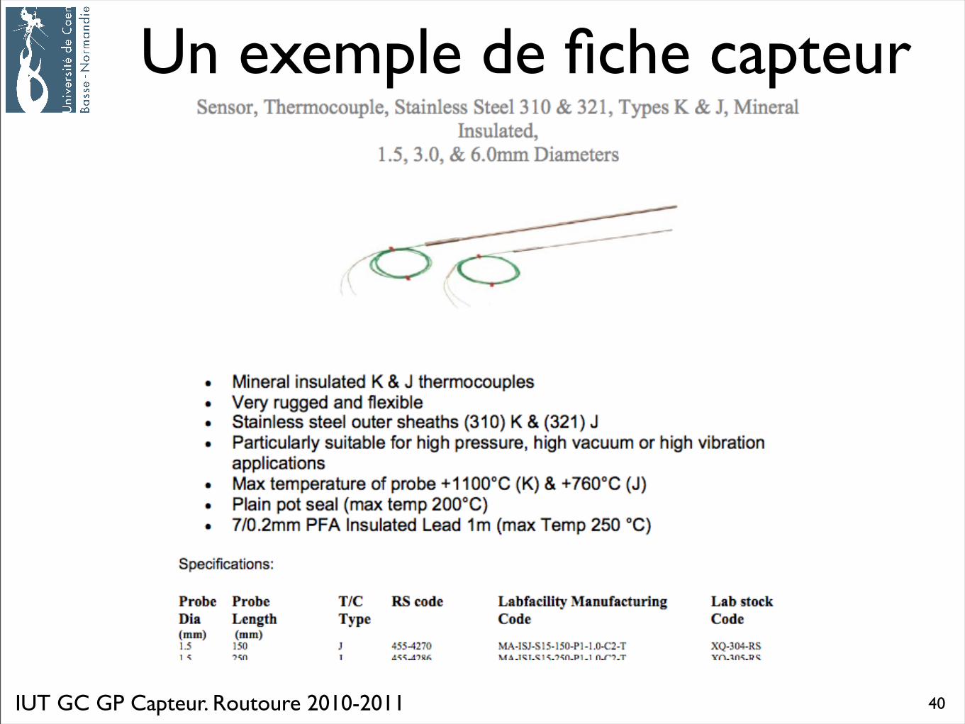
Un exemple de fiche capteur
40
Capteur de température6. Circuits intégrés : principe et quelques références
IUT GC GP Capteur. Routoure 2010-2011
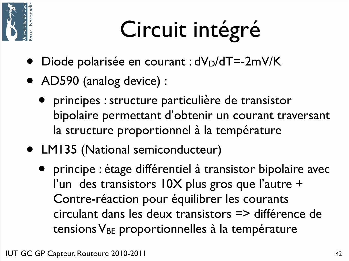
Circuit intégré • Diode polarisée en courant : dVD/dT=-2mV/K
• AD590 (analog device) :
• principes : structure particulière de transistor bipolaire permettant d’obtenir un courant traversant la structure proportionnel à la température
• LM135 (National semiconducteur)
• principe : étage différentiel à transistor bipolaire avec l’un des transistors 10X plus gros que l’autre + Contre-réaction pour équilibrer les courants circulant dans les deux transistors => différence de tensions VBE proportionnelles à la température
42
IUT GC GP Capteur. Routoure 2010-2011
AD590 (analog device)AD590
Rev. D | Page 6 of 16
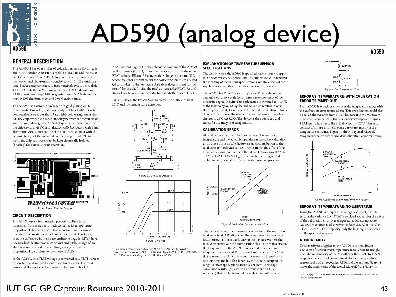
GENERAL DESCRIPTION The AD590H has 60 µ inches of gold plating on its Kovar leads and Kovar header. A resistance welder is used to seal the nickel cap to the header. The AD590 chip is eutectically mounted to the header and ultrasonically bonded to with 1 mil aluminum wire. Kovar composition: 53% iron nominal; 29% ± 1% nickel; 17% ± 1% cobalt; 0.65% manganese max; 0.20% silicon max; 0.10% aluminum max; 0.10% magnesium max; 0.10% zirconium max; 0.10% titanium max; and 0.06% carbon max.
The AD590F is a ceramic package with gold plating on its Kovar leads, Kovar lid, and chip cavity. Solder of 80/20 Au/Sn composition is used for the 1.5 mil thick solder ring under the lid. The chip cavity has a nickel underlay between the metallization and the gold plating. The AD590 chip is eutectically mounted in the chip cavity at 410°C and ultrasonically bonded to with 1 mil aluminum wire. Note that the chip is in direct contact with the ceramic base, not the metal lid. When using the AD590 in die form, the chip substrate must be kept electrically isolated (floating) for correct circuit operation.
!"# $%&'()*+ $,$*-$.-#)*/)-$+#01!0*22#%)3"*4)5602736/+8-!)!"#)3"*4)3$!$-69)560)%#!$*-+
,:
,;
<=2*-+
>>2*-+
00533-003
Figure 5. Metallization Diagram
CIRCUIT DESCRIPTION1
The AD590 uses a fundamental property of the silicon transistors from which it is made to realize its temperature proportional characteristic: if two identical transistors are operated at a constant ratio of collector current densities, r, then the difference in their base-emitter voltage is (kT/q)(In r). Because both k (Boltzman’s constant) and q (the charge of an electron) are constant, the resulting voltage is directly proportional to absolute temperature (PTAT).
In the AD590, this PTAT voltage is converted to a PTAT current by low temperature coefficient thin-film resistors. The total current of the device is then forced to be a multiple of this
PTAT current. Figure 6 is the schematic diagram of the AD590. In this figure, Q8 and Q11 are the transistors that produce the PTAT voltage. R5 and R6 convert the voltage to current. Q10, whose collector current tracks the collector currents in Q9 and Q11, supplies all the bias and substrate leakage current for the rest of the circuit, forcing the total current to be PTAT. R5 and R6 are laser-trimmed on the wafer to calibrate the device at 25°C.
Figure 7 shows the typical V–I characteristic of the circuit at 25°C and the temperature extremes.
00533-004
?@?=
0=@(<(!
?& ?A?<
3@=>B5?>
?C ?@=
0<@@D!
?E
?@(?'
3"*4+8.+!0$!#
?@@
@@E0&@<>!
0>E=(!
0@=>(!
:
;
0A&D!
Figure 6. Schematic Diagram
00533-005
( @ =
:@&(F3<=A
='E
=@E
:=&F3
* 68!)GH$I
;&&F3
A <
+844-J),6-!$9#)G,I
& > A(
Figure 7. V–I Plot
1 For a more detailed description, see M.P. Timko, “A Two-Terminal IC
Temperature Transducer,” IEEE J. Solid State Circuits, Vol. SC-11, p. 784-788, Dec. 1976. Understanding the Specifications–AD590.
AD590
Rev. D | Page 7 of 16
EXPLANATION OF TEMPERATURE SENSOR SPECIFICATIONS The way in which the AD590 is specified makes it easy to apply it in a wide variety of applications. It is important to understand the meaning of the various specifications and the effects of the supply voltage and thermal environment on accuracy.
The AD590 is a PTAT!
1 current regulator. That is, the output current is equal to a scale factor times the temperature of the sensor in degrees Kelvin. This scale factor is trimmed to 1 µA/K at the factory, by adjusting the indicated temperature (that is, the output current) to agree with the actual temperature. This is done with 5 V across the device at a temperature within a few degrees of 25°C (298.2K). The device is then packaged and tested for accuracy over temperature.
CALIBRATION ERROR At final factory test, the difference between the indicated temperature and the actual temperature is called the calibration error. Since this is a scale factory error, its contribution to the total error of the device is PTAT. For example, the effect of the 1°C specified maximum error of the AD590L varies from 0.73°C at –55°C to 1.42°C at 150°C. Figure 8 shows how an exaggerated calibration error would vary from the ideal over temperature.
00533-006
!"#$%"&
'()*'! +%$,-."/
'()*'
$01203"$%30,-45/
"#$%"&$3"678038%6#$!+6
!90"&$3"678038%6#$!+6
#"&!:3"$!+6033+3
Figure 8. Calibration Error vs. Temperature
The calibration error is a primary contributor to the maximum total error in all AD590 grades. However, because it is a scale factor error, it is particularly easy to trim. Figure 9 shows the most elementary way of accomplishing this. To trim this circuit, the temperature of the AD590 is measured by a reference temperature sensor and R is trimmed so that VT = 1 mV/K at that temperature. Note that when this error is trimmed out at one temperature, its effect is zero over the entire temperature range. In most applications, there is a current-to-voltage conversion resistor (or, as with a current input ADC, a reference) that can be trimmed for scale factor adjustment.
00533-007
;<
3=>>!
<$,?,=@<A5
"9;(>
(;>!
B
C
B
C
B
C
Figure 9. One Temperature Trim
ERROR VS. TEMPERATURE: WITH CALIBRATION ERROR TRIMMED OUT Each AD590 is tested for error over the temperature range with the calibration error trimmed out. This specification could also be called the variance from PTAT, because it is the maximum difference between the actual current over temperature and a PTAT multiplication of the actual current at 25°C. This error consists of a slope error and some curvature, mostly at the temperature extremes. Figure 10 shows a typical AD590K temperature curve before and after calibration error trimming.
"8$03#"&!:3"$!+6$3!1
00533-008
":7+&%$0,033+3,-4#/
'
>
C'C;; =;>
$01203"$%30,-4#/
#"&!:3"$!+6033+3
:08+30#"&!:3"$!+6$3!1
Figure 10. Effect to Scale Factor Trim on Accuracy
ERROR VS. TEMPERATURE: NO USER TRIMS Using the AD590 by simply measuring the current, the total error is the variance from PTAT, described above, plus the effect of the calibration error over temperature. For example, the AD590L maximum total error varies from 2.33°C at –55°C to 3.02°C at 150°C. For simplicity, only the large figure is shown on the specification page.
NONLINEARITY Nonlinearity as it applies to the AD590 is the maximum deviation of current over temperature from a best-fit straight line. The nonlinearity of the AD590 over the !55°C to +150°C range is superior to all conventional electrical temperature sensors such as thermocouples, RTDs, and thermistors. Figure 11 shows the nonlinearity of the typical AD590K from Figure 10. 1 T(°C) = T(K) ! 273.2. Zero on the Kelvin scale is absolute zero; there is no
lower temperature.
43
IUT GC GP Capteur. Routoure 2010-2011
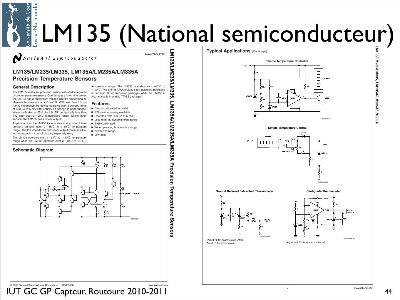
LM135 (National semiconducteur)LM135/LM235/LM335, LM135A/LM235A/LM335A
Precision Temperature Sensors
General DescriptionThe LM135 series are precision, easily-calibrated, integratedcircuit temperature sensors. Operating as a 2-terminal zener,the LM135 has a breakdown voltage directly proportional toabsolute temperature at +10 mV/˚K. With less than 1! dy-namic impedance the device operates over a current rangeof 400 µA to 5 mA with virtually no change in performance.When calibrated at 25˚C the LM135 has typically less than1˚C error over a 100˚C temperature range. Unlike othersensors the LM135 has a linear output.
Applications for the LM135 include almost any type of tem-perature sensing over a !55˚C to +150˚C temperaturerange. The low impedance and linear output make interfac-ing to readout or control circuitry especially easy.
The LM135 operates over a !55˚C to +150˚C temperaturerange while the LM235 operates over a !40˚C to +125˚C
temperature range. The LM335 operates from !40˚C to+100˚C. The LM135/LM235/LM335 are available packagedin hermetic TO-46 transistor packages while the LM335 isalso available in plastic TO-92 packages.
Featuresn Directly calibrated in ˚Kelvin
n 1˚C initial accuracy available
n Operates from 400 µA to 5 mA
n Less than 1! dynamic impedance
n Easily calibrated
n Wide operating temperature range
n 200˚C overrange
n Low cost
Schematic Diagram
DS005698-1
November 2000
LM135/LM235/LM335,LM135A/LM235A/LM335APrecisionTemperatureSensors
© 2000 National Semiconductor Corporation DS005698 www.national.com
Typical Applications (Continued)
Simple Temperature Controller
DS005698-5
Simple Temperature Control
DS005698-21
Ground Referred Fahrenheit Thermometer
DS005698-22
*Adjust R2 for 2.554V across LM336.
Adjust R1 for correct output.
Centigrade Thermometer
DS005698-23
*Adjust for 2.7315V at output of LM308
LM135/LM235/LM335,LM135A/LM235A/LM335A
www.national.com7
44

Capteur de température7. Pyromètres
IUT GC GP Capteur. Routoure 2010-2011
Pyromètre 1
• Principe : mesure du rayonnement thermique : on utilise la relation physique entre la température d’un corps et son rayonnement optique (infrarouge ou visible). On utilise pour cela, des capteurs thermiques, optiques ou photoélectriques.
• Intérêts :
• Mesure sans contact, sur des pièces en déplacement
• Températures très élevées ( jusqu’à plus de 2000°C)
• Mesures possibles en environnement agressif
• possibilité de thermographie
46
IUT GC GP Capteur. Routoure 2010-2011
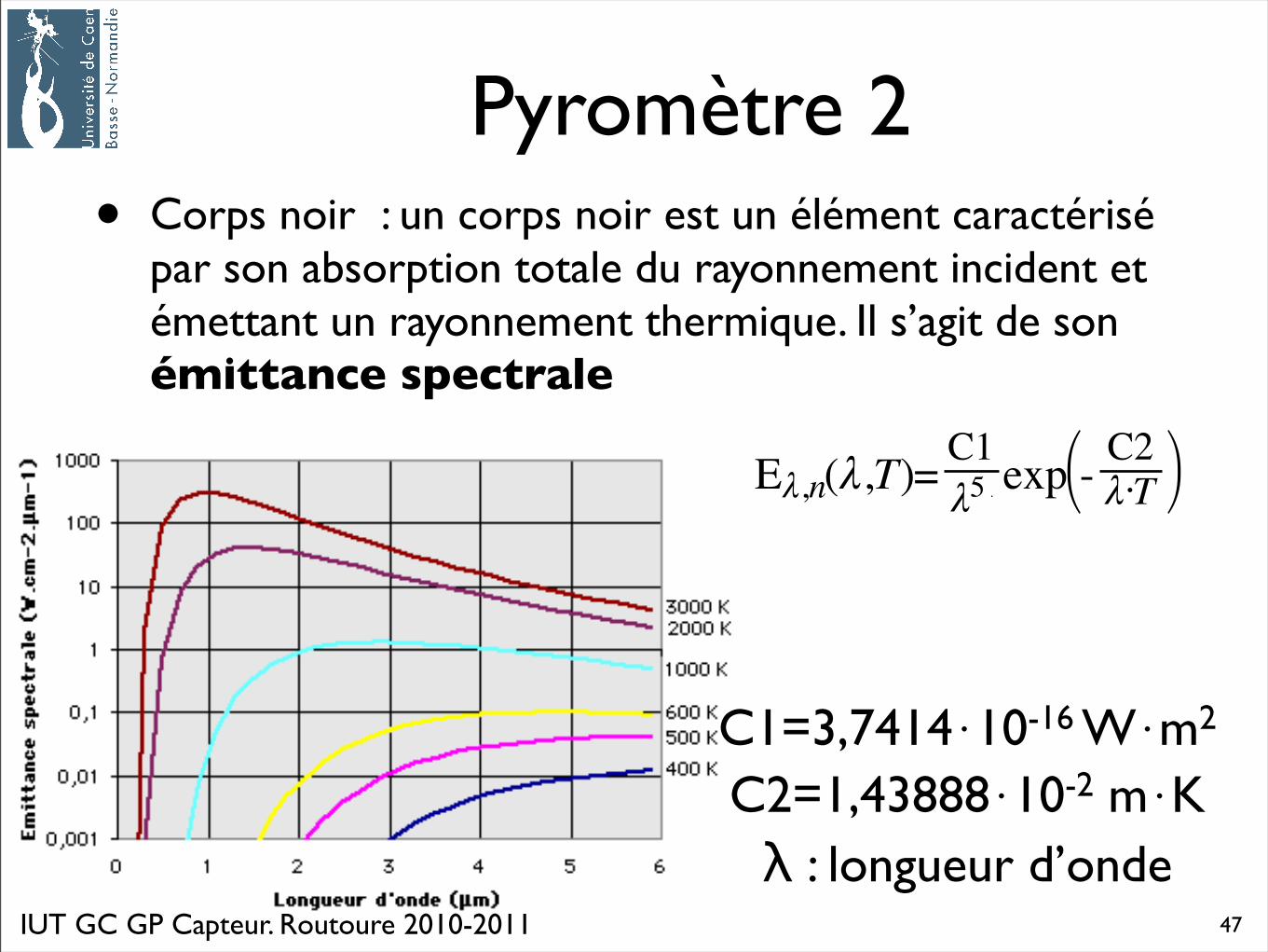
Pyromètre 2• Corps noir : un corps noir est un élément caractérisé
par son absorption totale du rayonnement incident et émettant un rayonnement thermique. Il s’agit de son émittance spectrale
C1=3,7414⋅10-16 W⋅m2
C2=1,43888⋅10-2 m⋅Kλ : longueur d’onde
47
IUT GC GP Capteur. Routoure 2010-2011
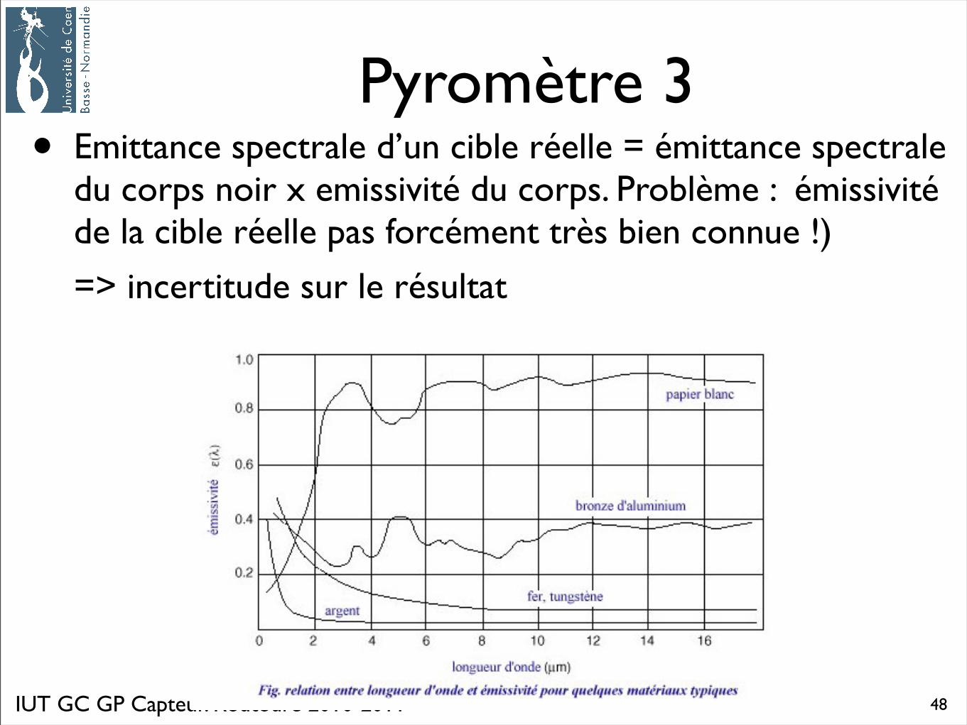
Pyromètre 3• Emittance spectrale d’un cible réelle = émittance spectrale
du corps noir x emissivité du corps. Problème : émissivité de la cible réelle pas forcément très bien connue !)
=> incertitude sur le résultat
48
IUT GC GP Capteur. Routoure 2010-2011
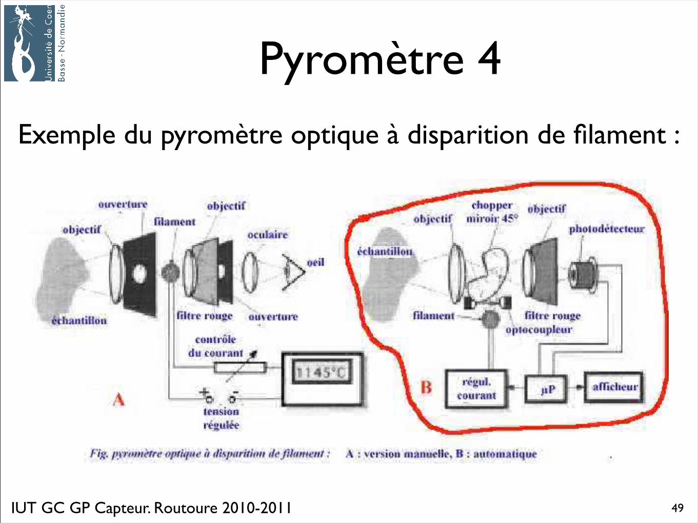
Pyromètre 4
Exemple du pyromètre optique à disparition de filament :
49
IUT GC GP Capteur. Routoure 2010-2011
Une explication en vidéo
50
IUT GC GP Capteur. Routoure 2010-2011
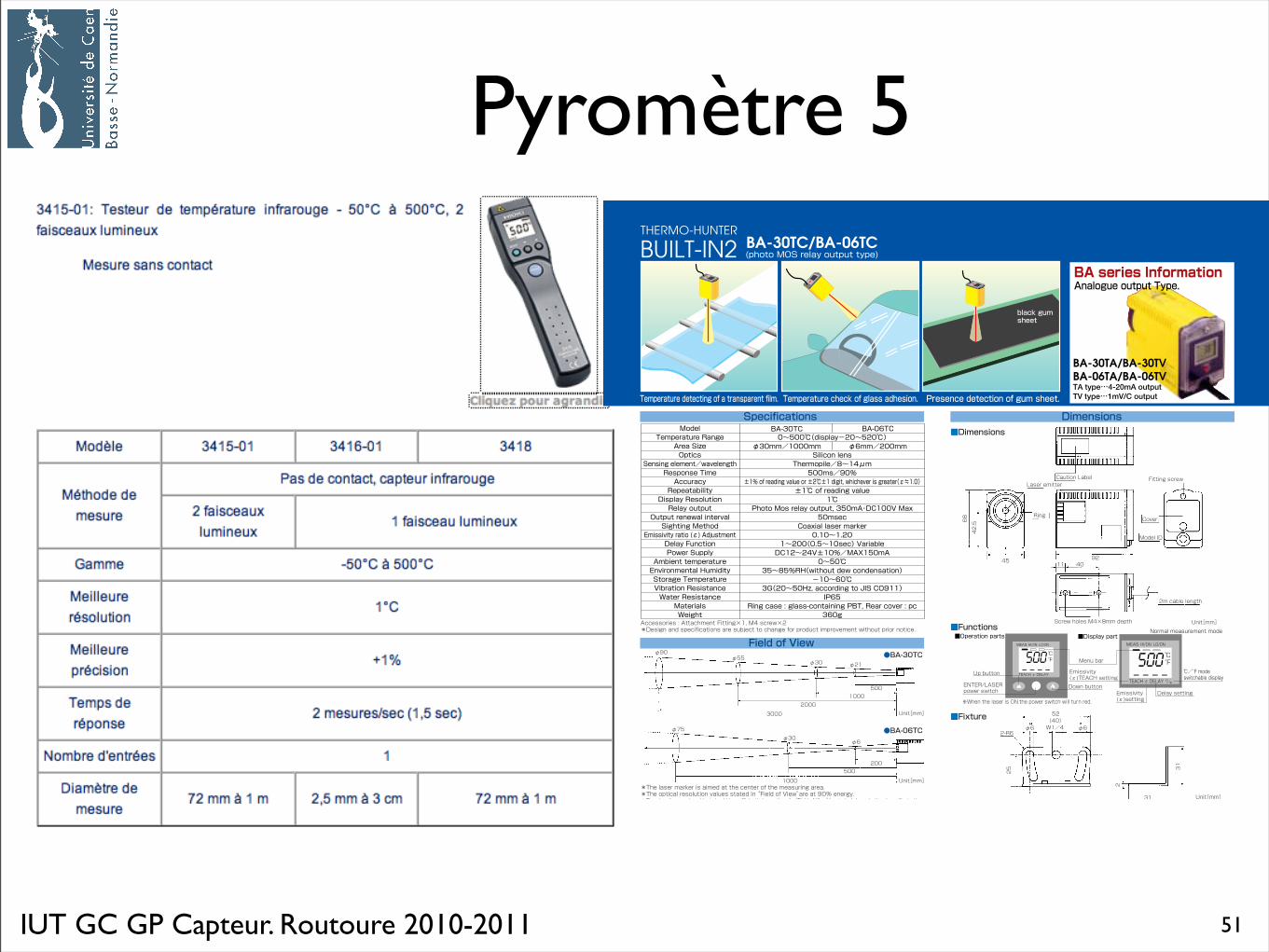
Pyromètre 5
51
IUT GC GP Capteur. Routoure 2010-2011
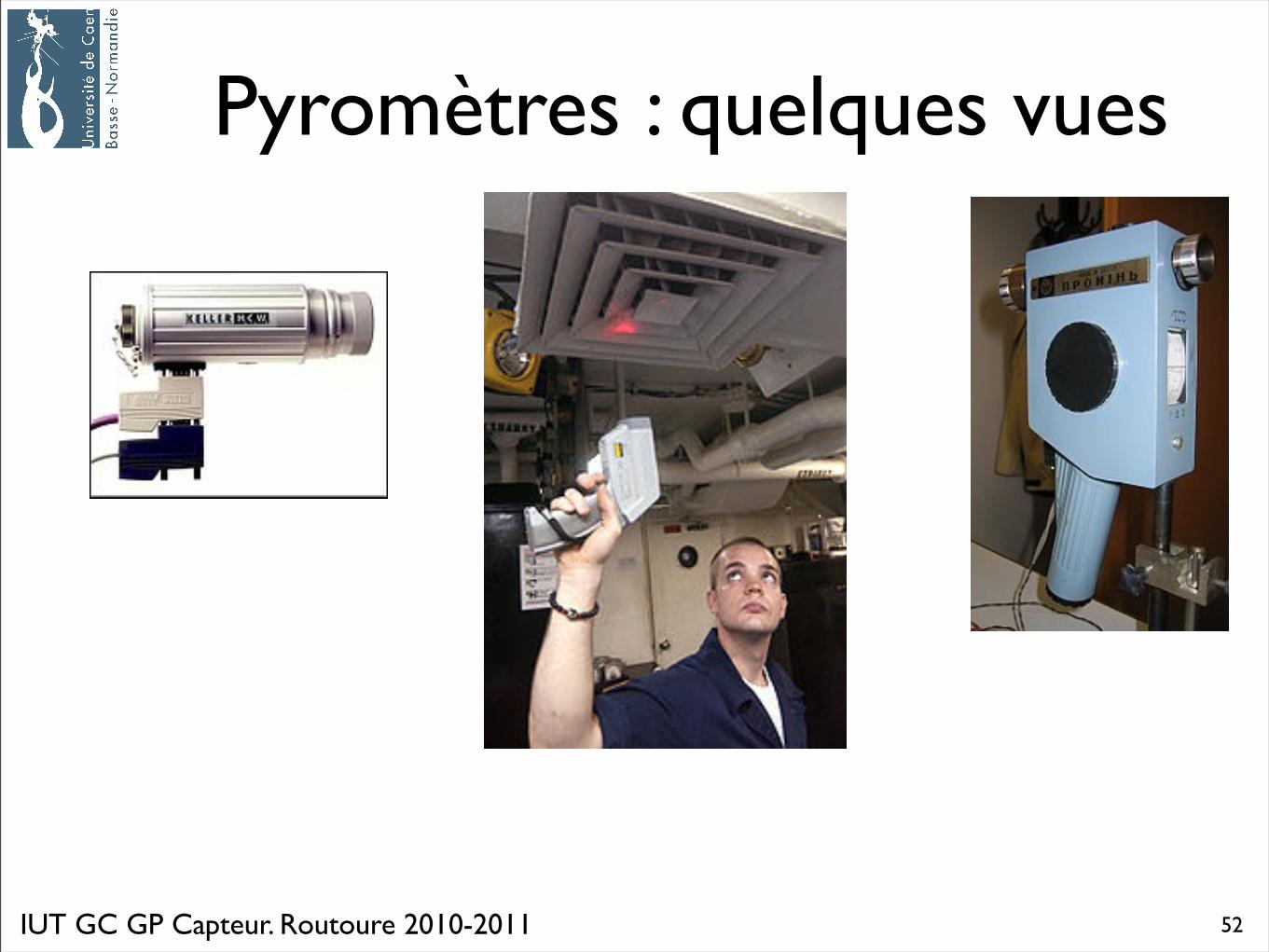
Pyromètres : quelques vues
52
Capteur de température8. Matrice de capteurs => vers les caméras
Recommended