Printed on recycled paper
Approved for public release; ditrobution is unlimited.
Publication in Technical Proceedings PR-NAVFAC-EXWC-CI-1602 JUNE 2016
Vortex-Induced Vibrations of a Riser with Design Variations
Robert F. Zueck

This page is intentionally left blank.
REPORT DOCUMENTATION PAGE Form Approved
OMB No. 0704-0188 Public reporting burden for this collection of information is estimated to average 1 hour per response, including the time for reviewing instructions, searching existing data sources, gathering and maintaining the data needed, and completing and reviewing this collection of information. Send comments regarding this burden estimate or any other aspect of this collection of information, including suggestions for reducing this burden to Department of Defense, Washington Headquarters Services, Directorate for Information Operations and Reports (0704-0188), 1215 Jefferson Davis Highway, Suite 1204, Arlington, VA 22202-4302. Respondents should be aware that notwithstanding any other provision of law, no person shall be subject to any penalty for failing to comply with a collection of information if it does not display a currently valid OMB control number. PLEASE DO NOT RETURN YOUR FORM TO THE ABOVE ADDRESS.
1. REPORT DATE (DD-MM-YYYY) 2. REPORT TYPE 3. DATES COVERED (From - To)
4. TITLE AND SUBTITLE 5a. CONTRACT NUMBER
5b. GRANT NUMBER
5c. PROGRAM ELEMENT NUMBER
6. AUTHOR(S) 5d. PROJECT NUMBER
5e. TASK NUMBER
5f. WORK UNIT NUMBER
7. PERFORMING ORGANIZATION NAME(S) AND ADDRESS(ES) 8. PERFORMING ORGANIZATION REPORTNUMBER
9. SPONSORING / MONITORING AGENCY NAME(S) AND ADDRESS(ES) 10. SPONSOR/MONITOR’S ACRONYM(S)
11. SPONSOR/MONITOR’S REPORT
NUMBER(S)
12. DISTRIBUTION / AVAILABILITY STATEMENT
13. SUPPLEMENTARY NOTES
14. ABSTRACT
15. SUBJECT TERMS
16. SECURITY CLASSIFICATION OF: 17. LIMITATION
OF ABSTRACT
18. NUMBEROF PAGES
19a. NAME OF RESPONSIBLE PERSON
a. REPORT b. ABSTRACT c. THIS PAGE 19b. TELEPHONE NUMBER (include area code)
Standard Form 298 (Re . 8-98) vPrescribed by ANSI Std. Z39.18
UU
Approved for public release; distribution unlimited.
This material is a work of the U.S. Government and is not subject to copyright protection in the United States. Approved for public release; distribution is unlimited 1
Proceedings of the ASME 2016 35th
International Conference on Ocean, Offshore and Arctic Engineering
OMAE2016
June 19 - 24, 2016, Busan, South Korea
OMAE2016-54990
VORTEX-INDUCED VIBRATIONS OF A RISER WITH DESIGN VARIATIONS
Robert F. Zueck US Navy - NAVFAC EXWC Port Hueneme, CA, USA
Email: [email protected]
ABSTRACT As meta-stable motions transverse to fluid flow in slender
bluff-bodied structures, Vortex-Induced Vibrations (VIV) are mostly determined by three-dimensional (3D) geometric and relativistic changes that evolve in the structure. Simplistic models of the structure ignore these key physical principles.
In a 2014 OMAE paper, we introduced the key physical concepts for simulating VIV in a horizontal-oriented slender structure (pipeline). In a 2015 OMAE paper, we re-oriented the same structure vertically to simulate VIV in a vertical riser.
In this paper, one or more of the following variations in the vertically-oriented riser will be made, in order to judge the physical effect each variation has on the character and distribution of VIV along the riser: Cyclically move the upper end of the vertical riser Change into an S-shaped riser by adding weight/buoyancy Disconnect the lower end of the S-shaped riser
The simulations help show and reinforce the following mechanical concepts of VIV: How gravity and fluid drag evolves a 3D shape in the riser How this shape creates specific structural flexibilities How these flexibilities set the stage for specific VIV How tension and end conditions are vital to VIV behavior
INTRODUCTION In a previous OMAE paper [Zueck & Palo, 2014], we
addressed the basic mechanics of VIV. We simulated VIV for a horizontally-suspended pipeline using a highly nonlinear physics-based structural model. To this structural model, we added relationships for representing fluid/structure interaction in a relativistic and evolutionary manner. Simulations of several experiments confirmed the validity of this unique approach.
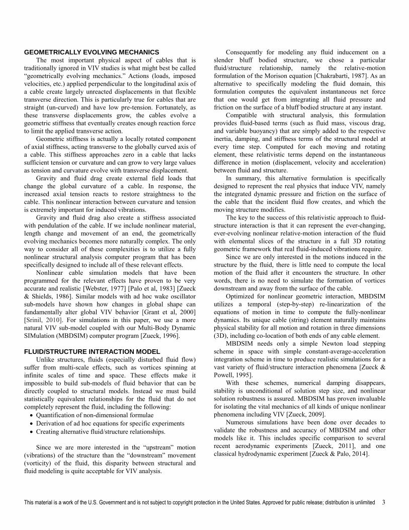
In a subsequent OMAE paper [Zueck, 2015], we re-oriented the same slender structure in the vertical direction to create a typical marine riser. Simulations helped physically explain the similarities and differences in VIV responses for the two different orientations of the same structure in the same fluid flow field. Figure 1 represents the closest comparison that could be found between the two orientations.
Fig 1: VIV at middle node of a flexible pipe, oriented
horizontally as a suspended pipeline (left plot) and
vertically as a marine riser (right plot)
As compared to the vertical riser, the figure “8” shape for the horizontal pipeline is very narrow and tall, leans strongly with respect to the vertical, and is in a much more downward deflected global position. These differences result mostly from gravity acting transverse to pipeline, but longitudinal to the riser. Other comparisons show more dramatic differences.
In this paper, we first explain the physical basis of our modeling, followed by simulations for a horizontal pipeline. We
This material is a work of the U.S. Government and is not subject to copyright protection in the United States. Approved for public release; distribution is unlimited 2
then re-orient this model to the vertical and show how specific variations in design of marine risers physically affect the character and distribution of VIV.
A NEW BASIS FOR VIV MODELING AND SIMULATION In the many simulations leading up to this paper, we have
extensively studied how natural changes in the following key physical quantities affect the vibrational response of a broad range of slender structures [Zueck, 2008]: Basic structural and fluid properties Axial tension and fluid velocity Structural and fluid mass Structural and fluid stiffness Local geometric rotations and orientations in 3D Global shape and pendulation in 3D
These natural changes act (often subtly) across broad scalesof time and space to influence fluid/structure interaction in often highly interdependent ways. Still largely ignored in nearly all models available today, these changes can occur both within and between cycles of vibration. These changes can be both relativistic (dependent on relative motion differences) and evolutionary (changing over long time periods).
For example, natural nonlinear shifts in the vibrational resonance of a cable (string) can physically explain “lock-in”, a VIV complexity that is normally attributed to changes mostly in the fluid. In other words, the “resonant period” of a real cable and its associated stiffness are not constant. Both shift as the cable deflects under greater drag from increased fluid flow velocity. We have shown this shift to be very close to widely published measurements for “lock-in” [Zueck, 2007].
In addition, many types of inducements, such as imposing an initial transverse velocity in the structure, can generate vibrations that look just like VIV [Zueck, 2007]. This repeatable behavior to non-specific inducements is the primary reason for the author’s long standing postulation that the fundamental basis of VIV is foremost structural [Zueck, 1997].
PHYSICS-BASED STRUCTURAL MODELING For modeling fluid-induced motion of a structure, we use a
fully-nonlinear physics-based structural model. To this structural model, we can add a variety of semi-empirical relative-motion fluid/structure interaction relationships. In such a structure-centric model, the fluid acts upon and moves the structure. The structure does not alter the flow of fluid.
This type of fluid/structure interaction model focuses on the deterministic equations of a Newtonian dynamical system, as opposed to the statistical models that have historically dominated traditional fluid modeling and VIV research.
Unlike statistical models, Newtonian dynamical models are capable of determining cause and effect (causality) [Argyris et al, 1994]. These deterministic models are thus capable of confirming how the fluid does or does not induce motion and vibrations in the structure.
It is important to note that the physics of the model does not need to represent all realism at all time and space scales, but rather, only those specific physical aspects that are critical to the desired realism. Only then will the amazing breadth of VIV be revealed in unencumbered simulations.
For the purpose of simulating global structural responses (like VIV) in pipelines and risers of any appreciable length, bending and torsional deformation can be ignored. In comparison to the potential energy in axial strain, bending energy drops off rapidly with slenderness (diameter/length higher than ~50). Similarly, torsional energy is near zero in bluff, symmetrical and slender structures [Zueck, 2008].
For general application to an infinite variety of design variations in the pipeline or riser design, we chose to discretize the structure spatially into a simple series of inter-connected local cable (string) elements. Each element need only have a simple material relationship between axial deformation and tension. This relationship and any other properties for the element (such as length) are allowed to vary from element to element as needed over all space and time.
By adding terms associated with local relative-motion dynamics (acceleration-based mass, velocity-based drag, and displacement-based contacts) to each element, one creates a nodal system of motion equations for generalized integration into global solutions of system response. If updated as nonlinear changes occur, this system of equations is able to reveal the full nature of VIV in a very generalized and realistic fashion.
It is popular to assume a linear superimposed set of Eigen-frequencies and Eigen-modes as the pre-supposed global solution basis over all time and space for one unchanging system of equations. Unfortunately, these frequency domain solutions are too idealized, linearized, orthogonal, and otherwise constrained for VIV realism in 3D [Zueck, 2015].
Recognizing the nonlinear relativistic and evolutionary changes in the local state of the structure (and in its interaction with the fluid), it is best to re-compute the system of equations at every time step to ensure a much more physically accurate representation of motion (or vibration) over time and space. Often referred to as a time domain solution, the evolutionary vibrations may appear “chaotic” (drifting resonance and shifting modes) to the classical frequency domain analyst.
Not all nonlinear models are created equally. Any model that idealizes, simplifies or otherwise misrepresents relevant natural physical phenomena will generate unreal and inaccurate results. Similarly, any experiment that idealizes, simplifies or otherwise misrepresents relevant natural physical phenomena will generate unreal and inaccurate data.
Traditional analysts often ignore key elements of realism because it does not fit the measurement methods, the analytics, the idealized coordinates, the linear solution methods, or other analytical desires. With modern digital computational tools, we no longer need to make such neglectful assumptions.
This material is a work of the U.S. Government and is not subject to copyright protection in the United States. Approved for public release; distribution is unlimited 3
GEOMETRICALLY EVOLVING MECHANICS The most important physical aspect of cables that is
traditionally ignored in VIV studies is what might best be called “geometrically evolving mechanics.” Actions (loads, imposed velocities, etc.) applied perpendicular to the longitudinal axis of a cable create largely unreacted displacements in that flexible transverse direction. This is particularly true for cables that are straight (un-curved) and have low pre-tension. Fortunately, as these transverse displacements grow, the cables evolve a geometric stiffness that eventually creates enough reaction force to limit the applied transverse action.
Geometric stiffness is actually a locally rotated component of axial stiffness, acting transverse to the globally curved axis of a cable. This stiffness approaches zero in a cable that lacks sufficient tension or curvature and can grow to very large values as tension and curvature evolve with transverse displacement.
Gravity and fluid drag create external field loads that change the global curvature of a cable. In response, the increased axial tension reacts to restore straightness to the cable. This nonlinear interaction between curvature and tension is extremely important for induced vibrations.
Gravity and fluid drag also create a stiffness associated with pendulation of the cable. If we include nonlinear material, length change and movement of an end, the geometrically evolving mechanics becomes more naturally complex. The only way to consider all of these complexities is to utilize a fully nonlinear structural analysis computer program that has been specifically designed to include all of these relevant effects.
Nonlinear cable simulation models that have been programmed for the relevant effects have proven to be very accurate and realistic [Webster, 1977] [Palo et al, 1983] [Zueck & Shields, 1986]. Similar models with ad hoc wake oscillator sub-models have shown how changes in global shape can fundamentally alter global VIV behavior [Grant et al, 2000] [Srinil, 2010]. For simulations in this paper, we use a more natural VIV sub-model coupled with our Multi-Body Dynamic SIMulation (MBDSIM) computer program [Zueck, 1996].
FLUID/STRUCTURE INTERACTION MODEL Unlike structures, fluids (especially disturbed fluid flow)
suffer from multi-scale effects, such as vortices spinning at infinite scales of time and space. These effects make it impossible to build sub-models of fluid behavior that can be directly coupled to structural models. Instead we must build statistically equivalent relationships for the fluid that do not completely represent the fluid, including the following: Quantification of non-dimensional formulae Derivation of ad hoc equations for specific experiments Creating alternative fluid/structure relationships.
Since we are more interested in the “upstream” motion (vibrations) of the structure than the “downstream” movement (vorticity) of the fluid, this disparity between structural and fluid modeling is quite acceptable for VIV analysis.
Consequently for modeling any fluid inducement on a slender bluff bodied structure, we chose a particular fluid/structure relationship, namely the relative-motion formulation of the Morison equation [Chakrabarti, 1987]. As an alternative to specifically modeling the fluid domain, this formulation computes the equivalent instantaneous net force that one would get from integrating all fluid pressure and friction on the surface of a bluff bodied structure at any instant.
Compatible with structural analysis, this formulation provides fluid-based terms (such as fluid mass, viscous drag, and variable buoyancy) that are simply added to the respective inertia, damping, and stiffness terms of the structural model at every time step. Computed for each moving and rotating element, these relativistic terms depend on the instantaneous difference in motion (displacement, velocity and acceleration) between fluid and structure.
In summary, this alternative formulation is specifically designed to represent the real physics that induce VIV, namely the integrated dynamic pressure and friction on the surface of the cable that the incident fluid flow creates, and which the moving structure modifies.
The key to the success of this relativistic approach to fluid-structure interaction is that it can represent the ever-changing, ever-evolving nonlinear relative-motion interaction of the fluid with elemental slices of the structure in a full 3D rotating geometric framework that real fluid-induced vibrations require.
Since we are only interested in the motions induced in the structure by the fluid, there is little need to compute the local motion of the fluid after it encounters the structure. In other words, there is no need to simulate the formation of vortices downstream and away from the surface of the cable.
Optimized for nonlinear geometric interaction, MBDSIM utilizes a temporal (step-by-step) re-linearization of the equations of motion in time to compute the fully-nonlinear dynamics. Its unique cable (string) element naturally maintains physical stability for all motion and rotation in three dimensions (3D), including co-location of both ends of any cable element.
MBDSIM needs only a simple Newton load stepping scheme in space with simple constant-average-acceleration integration scheme in time to produce realistic simulations for a vast variety of fluid/structure interaction phenomena [Zueck & Powell, 1995].
With these schemes, numerical damping disappears, stability is unconditional of solution step size, and nonlinear solution robustness is assured. MBDSIM has proven invaluable for isolating the vital mechanics of all kinds of unique nonlinear phenomena including VIV [Zueck, 2009].
Numerous simulations have been done over decades to validate the robustness and accuracy of MBDSIM and other models like it. This includes specific comparison to several recent aerodynamic experiments [Zueck, 2011], and one classical hydrodynamic experiment [Zueck & Palo, 2014].
This material is a work of the U.S. Government and is not subject to copyright protection in the United States. Approved for public release; distribution is unlimited 4
MODELING EXPERIMENTAL PIPELINE A series of VIV experiments were conducted near Castine,
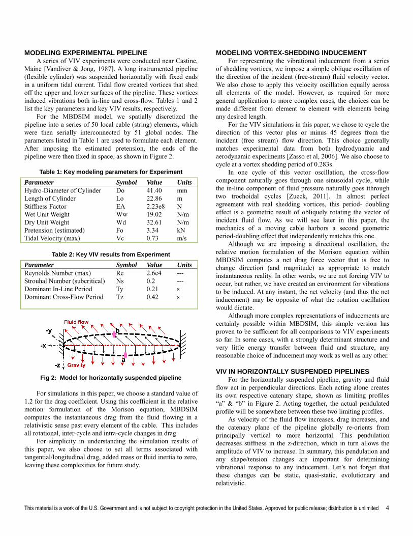
Maine [Vandiver & Jong, 1987]. A long instrumented pipeline (flexible cylinder) was suspended horizontally with fixed ends in a uniform tidal current. Tidal flow created vortices that shed off the upper and lower surfaces of the pipeline. These vortices induced vibrations both in-line and cross-flow. Tables 1 and 2 list the key parameters and key VIV results, respectively.
For the MBDSIM model, we spatially discretized the pipeline into a series of 50 local cable (string) elements, which were then serially interconnected by 51 global nodes. The parameters listed in Table 1 are used to formulate each element. After imposing the estimated pretension, the ends of the pipeline were then fixed in space, as shown in Figure 2.
Table 1: Key modeling parameters for Experiment
Parameter Symbol Value Units
Hydro-Diameter of Cylinder Do 41.40 mm Length of Cylinder Lo 22.86 m Stiffness Factor EA 2.23e8 N Wet Unit Weight Ww 19.02 N/m Dry Unit Weight Wd 32.61 N/m Pretension (estimated) Fo 3.34 kN Tidal Velocity (max) Vc 0.73 m/s
Table 2: Key VIV results from Experiment
Parameter Symbol Value Units
Reynolds Number (max) Re 2.6e4 --- Strouhal Number (subcritical) Ns 0.2 --- Dominant In-Line Period Ty 0.21 s Dominant Cross-Flow Period Tz 0.42 s
Fig 2: Model for horizontally suspended pipeline
For simulations in this paper, we choose a standard value of
1.2 for the drag coefficient. Using this coefficient in the relative motion formulation of the Morison equation, MBDSIM computes the instantaneous drag from the fluid flowing in a relativistic sense past every element of the cable. This includes all rotational, inter-cycle and intra-cycle changes in drag.
For simplicity in understanding the simulation results of this paper, we also choose to set all terms associated with tangential/longitudinal drag, added mass or fluid inertia to zero, leaving these complexities for future study.
MODELING VORTEX-SHEDDING INDUCEMENT For representing the vibrational inducement from a series
of shedding vortices, we impose a simple oblique oscillation of the direction of the incident (free-stream) fluid velocity vector. We also chose to apply this velocity oscillation equally across all elements of the model. However, as required for more general application to more complex cases, the choices can be made different from element to element with elements being any desired length.
For the VIV simulations in this paper, we chose to cycle the direction of this vector plus or minus 45 degrees from the incident (free stream) flow direction. This choice generally matches experimental data from both hydrodynamic and aerodynamic experiments [Zasso et al, 2006]. We also choose to cycle at a vortex shedding period of 0.283s.
In one cycle of this vector oscillation, the cross-flow component naturally goes through one sinusoidal cycle, while the in-line component of fluid pressure naturally goes tthrough two trochoidal cycles [Zueck, 2011]. In almost perfect agreement with real shedding vortices, this period- doubling effect is a geometric result of obliquely rotating the vector of incident fluid flow. As we will see later in this paper, the mechanics of a moving cable harbors a second geometric period-doubling effect that independently matches this one.
Although we are imposing a directional oscillation, the relative motion formulation of the Morison equation within MBDSIM computes a net drag force vector that is free to change direction (and magnitude) as appropriate to match instantaneous reality. In other words, we are not forcing VIV to occur, but rather, we have created an environment for vibrations to be induced. At any instant, the net velocity (and thus the net inducement) may be opposite of what the rotation oscillation would dictate.
Although more complex representations of inducements are certainly possible within MBDSIM, this simple version has proven to be sufficient for all comparisons to VIV experiments so far. In some cases, with a strongly determinant structure and very little energy transfer between fluid and structure, any reasonable choice of inducement may work as well as any other.
VIV IN HORIZONTALLY SUSPENDED PIPELINES For the horizontally suspended pipeline, gravity and fluid
flow act in perpendicular directions. Each acting alone creates its own respective catenary shape, shown as limiting profiles “a” & “b” in Figure 2. Acting together, the actual pendulated profile will be somewhere between these two limiting profiles.
As velocity of the fluid flow increases, drag increases, and the catenary plane of the pipeline globally re-orients from principally vertical to more horizontal. This pendulation decreases stiffness in the z-direction, which in turn allows the amplitude of VIV to increase. In summary, this pendulation and any shape/tension changes are important for determining vibrational response to any inducement. Let’s not forget that these changes can be static, quasi-static, evolutionary and relativistic.
This material is a work of the U.S. Government and is not subject to copyright protection in the United States. Approved for public release; distribution is unlimited 5
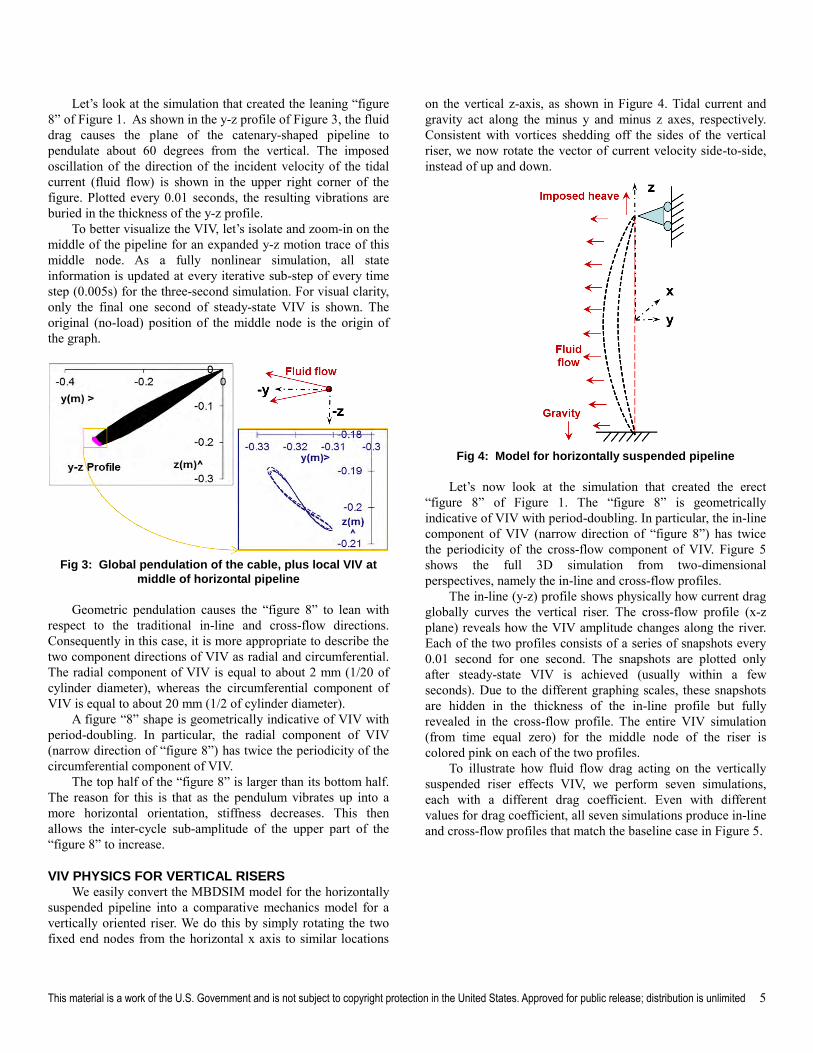
Let’s look at the simulation that created the leaning “figure 8” of Figure 1. As shown in the y-z profile of Figure 3, the fluid drag causes the plane of the catenary-shaped pipeline to pendulate about 60 degrees from the vertical. The imposed oscillation of the direction of the incident velocity of the tidal current (fluid flow) is shown in the upper right corner of the figure. Plotted every 0.01 seconds, the resulting vibrations are buried in the thickness of the y-z profile.
To better visualize the VIV, let’s isolate and zoom-in on the middle of the pipeline for an expanded y-z motion trace of this middle node. As a fully nonlinear simulation, all state information is updated at every iterative sub-step of every time step (0.005s) for the three-second simulation. For visual clarity, only the final one second of steady-state VIV is shown. The original (no-load) position of the middle node is the origin of the graph.
Fig 3: Global pendulation of the cable, plus local VIV at
middle of horizontal pipeline
Geometric pendulation causes the “figure 8” to lean with respect to the traditional in-line and cross-flow directions. Consequently in this case, it is more appropriate to describe the two component directions of VIV as radial and circumferential. The radial component of VIV is equal to about 2 mm (1/20 of cylinder diameter), whereas the circumferential component of VIV is equal to about 20 mm (1/2 of cylinder diameter).
A figure “8” shape is geometrically indicative of VIV with period-doubling. In particular, the radial component of VIV (narrow direction of “figure 8”) has twice the periodicity of the circumferential component of VIV.
The top half of the “figure 8” is larger than its bottom half. The reason for this is that as the pendulum vibrates up into a more horizontal orientation, stiffness decreases. This then allows the inter-cycle sub-amplitude of the upper part of the “figure 8” to increase.
VIV PHYSICS FOR VERTICAL RISERS We easily convert the MBDSIM model for the horizontally
suspended pipeline into a comparative mechanics model for a vertically oriented riser. We do this by simply rotating the two fixed end nodes from the horizontal x axis to similar locations
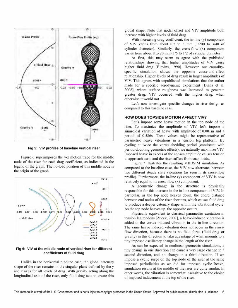
on the vertical z-axis, as shown in Figure 4. Tidal current and gravity act along the minus y and minus z axes, respectively. Consistent with vortices shedding off the sides of the vertical riser, we now rotate the vector of current velocity side-to-side, instead of up and down.
Fig 4: Model for horizontally suspended pipeline
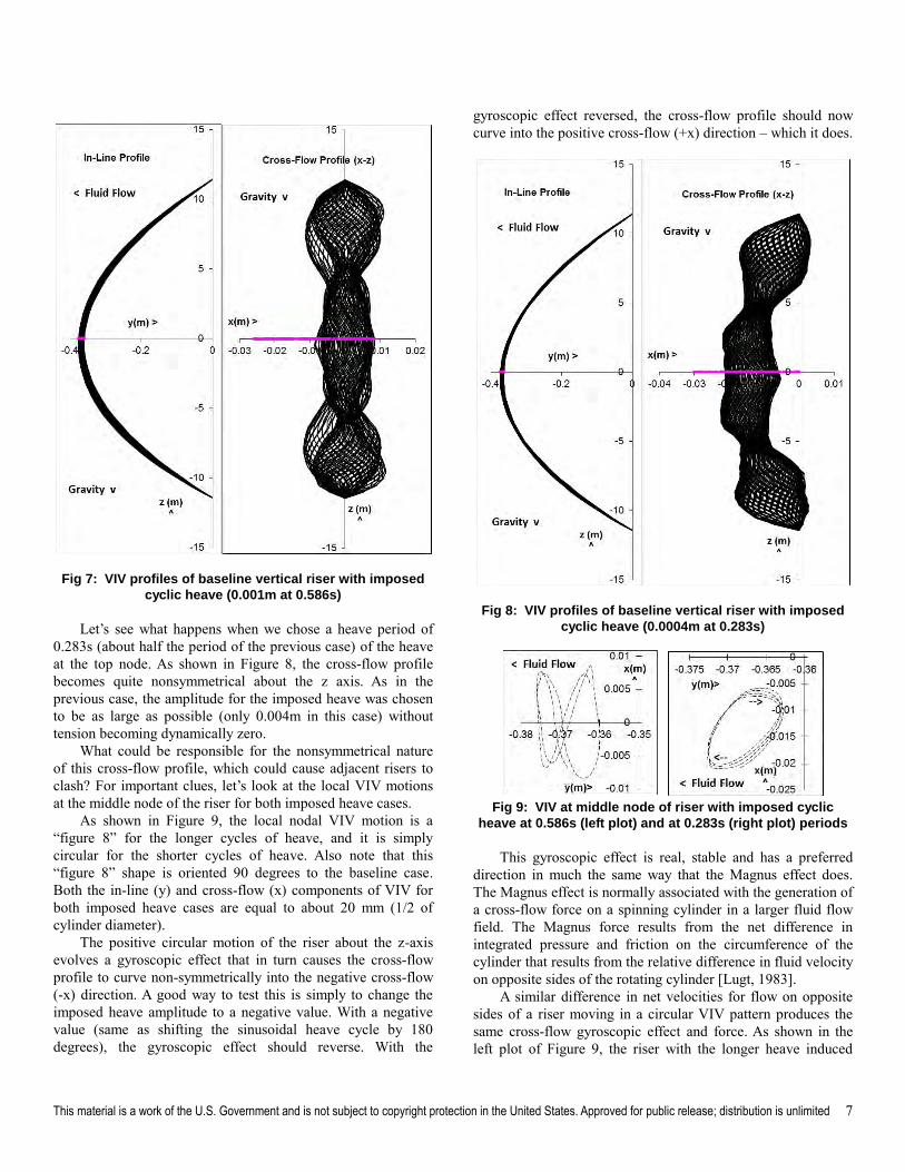
Let’s now look at the simulation that created the erect “figure 8” of Figure 1. The “figure 8” is geometrically indicative of VIV with period-doubling. In particular, the in-line component of VIV (narrow direction of “figure 8”) has twice the periodicity of the cross-flow component of VIV. Figure 5 shows the full 3D simulation from two-dimensional perspectives, namely the in-line and cross-flow profiles.
The in-line (y-z) profile shows physically how current drag globally curves the vertical riser. The cross-flow profile (x-z plane) reveals how the VIV amplitude changes along the river. Each of the two profiles consists of a series of snapshots every 0.01 second for one second. The snapshots are plotted only after steady-state VIV is achieved (usually within a few seconds). Due to the different graphing scales, these snapshots are hidden in the thickness of the in-line profile but fully revealed in the cross-flow profile. The entire VIV simulation (from time equal zero) for the middle node of the riser is colored pink on each of the two profiles.
To illustrate how fluid flow drag acting on the vertically suspended riser effects VIV, we perform seven simulations, each with a different drag coefficient. Even with different values for drag coefficient, all seven simulations produce in-line and cross-flow profiles that match the baseline case in Figure 5.
This material is a work of the U.S. Government and is not subject to copyright protection in the United States. Approved for public release; distribution is unlimited 6
Fig 5: VIV profiles of baseline vertical riser
Figure 6 superimposes the y-z motion trace for the middle node of the riser for each drag coefficient, as indicated in the legend of the graph. The no-load position of this middle node is the origin of the graph.
Fig 6: VIV at the middle node of vertical riser for different
coefficients of fluid drag
Unlike in the horizontal pipeline case, the global catenary shape of the riser remains in the singular plane defined by the y and z axes for all levels of drag. With gravity acting along the longitudinal axis of the riser, only fluid drag acts to create this
global shape. Note that nodal offset and VIV amplitude both increase with higher levels of fluid drag.
With increasing drag coefficient, the in-line (y) component of VIV varies from about 0.2 to 3 mm (1/200 to 3/40 of cylinder diameter). Similarly, the cross-flow (x) component varies from about 8 to 20 mm (1/5 to 1/2 of cylinder diameter).
At first, this may seem to agree with the published relationships showing that higher amplitudes of VIV cause higher fluid drag [Blevins, 1990]. However, our causality-specific simulation shows the opposite cause-and-effect relationship. Higher levels of drag result in larger amplitudes of VIV. This agrees with unpublished simulations that the authormade for a specific aerodynamic experiment [Diana et al, 2008], where surface roughness was increased to generate greater drag. VIV occurred with the higher drag, when otherwise it would not.
Let’s now investigate specific changes in riser design as compared to this baseline case.
HOW DOES TOPSIDE MOTION AFFECT VIV? Let’s impose some heave motion in the top node of the
riser. To maximize the amplitude of VIV, let’s impose a sinusoidal variation of heave with amplitude of 0.001m and a period of 0.586s. These values might be representative of parametric heave vibrations in a tension leg platform. By cycling at twice the vortex-shedding period (consistent with period-doubling geometric effects), we naturally maximize VIV. Imposed heave in excess of the chosen amplitude causes tension to approach zero, and the riser suffers from snap loads.
Figure 7 illustrates the resulting MBDSIM simulation. As compared to the baseline case, the VIV now alternates between two different steady state vibrations (as seen in its cross-flow profile). Furthermore, the in-line (y) component of VIV is now relatively equal to its cross-flow (x) component.
A geometric change in the structure is physically responsible for this increase in the in-line component of VIV. In particular, as the top node heaves down, the chord distance between end nodes of the riser shortens, which causes fluid drag to produce a deeper catenary shape within the vibrational cycle. As the top node heaves up, the opposite occurs.
Physically equivalent to classical parametric excitation in tension leg tendons [Zueck, 2007], a heave-induced vibration is added to the vortex-induced vibration in the in-line direction. The same heave induced vibration does not occur in the cross-flow direction, because there is no field force (fluid drag or gravity) in this direction to take advantage of what amounts to a tiny imposed oscillatory change in the length of the riser.
As can be expected in nonlinear geometric simulations, a tiny change in one direction can cause a very large change in a second direction, and no change in a third direction. If we impose a cyclic surge on the top node of the riser at the same imposed periodicities as we did for imposed cyclic heave, simulation results at the middle of the riser are quite similar. In other words, the vibration is somewhat insensitive to the choice of imposed inducement at the top of the riser.
This material is a work of the U.S. Government and is not subject to copyright protection in the United States. Approved for public release; distribution is unlimited 7
Fig 7: VIV profiles of baseline vertical riser with imposed
cyclic heave (0.001m at 0.586s)
Let’s see what happens when we chose a heave period of 0.283s (about half the period of the previous case) of the heave at the top node. As shown in Figure 8, the cross-flow profile becomes quite nonsymmetrical about the z axis. As in the previous case, the amplitude for the imposed heave was chosen to be as large as possible (only 0.004m in this case) without tension becoming dynamically zero.
What could be responsible for the nonsymmetrical nature of this cross-flow profile, which could cause adjacent risers to clash? For important clues, let’s look at the local VIV motions at the middle node of the riser for both imposed heave cases.
As shown in Figure 9, the local nodal VIV motion is a “figure 8” for the longer cycles of heave, and it is simply circular for the shorter cycles of heave. Also note that this “figure 8” shape is oriented 90 degrees to the baseline case. Both the in-line (y) and cross-flow (x) components of VIV for both imposed heave cases are equal to about 20 mm (1/2 of cylinder diameter).
The positive circular motion of the riser about the z-axis evolves a gyroscopic effect that in turn causes the cross-flow profile to curve non-symmetrically into the negative cross-flow (-x) direction. A good way to test this is simply to change the imposed heave amplitude to a negative value. With a negative value (same as shifting the sinusoidal heave cycle by 180 degrees), the gyroscopic effect should reverse. With the
gyroscopic effect reversed, the cross-flow profile should now curve into the positive cross-flow (+x) direction – which it does.
Fig 8: VIV profiles of baseline vertical riser with imposed
cyclic heave (0.0004m at 0.283s)
Fig 9: VIV at middle node of riser with imposed cyclic
heave at 0.586s (left plot) and at 0.283s (right plot) periods
This gyroscopic effect is real, stable and has a preferred direction in much the same way that the Magnus effect does. The Magnus effect is normally associated with the generation of a cross-flow force on a spinning cylinder in a larger fluid flow field. The Magnus force results from the net difference in integrated pressure and friction on the circumference of the cylinder that results from the relative difference in fluid velocity on opposite sides of the rotating cylinder [Lugt, 1983].
A similar difference in net velocities for flow on opposite sides of a riser moving in a circular VIV pattern produces the same cross-flow gyroscopic effect and force. As shown in the left plot of Figure 9, the riser with the longer heave induced
This material is a work of the U.S. Government and is not subject to copyright protection in the United States. Approved for public release; distribution is unlimited 8
period (Figure 7) vibrates in a “figure 8” and thus does not evolve a Magnus effect. The opposing Magnus forces of the two opposing rotations in the “figure 8” simply cancel each other.
As shown in the right plot of Figure 9, the riser with the shorter heave induced period (Figure 8) vibrates in a single circular pattern. Rotating clockwise, the cable surface sees the lowest relative velocity (and thus the highest pressure) at the top of the circle. This higher pressure shifts the riser in the negative cross-flow (-x) direction.
Although the actual inducement is pressure-based, MBDSIM evolves this gyroscopic effect through the instantaneous relative-motion velocity-squared drag term in the relative-motion formulation of the Morison Equation, just like it does for any other fluid-induced motion. We did not expect the Magnus force and its cross-flow displacement to appear in our simulation, and thus encourage independent verification.
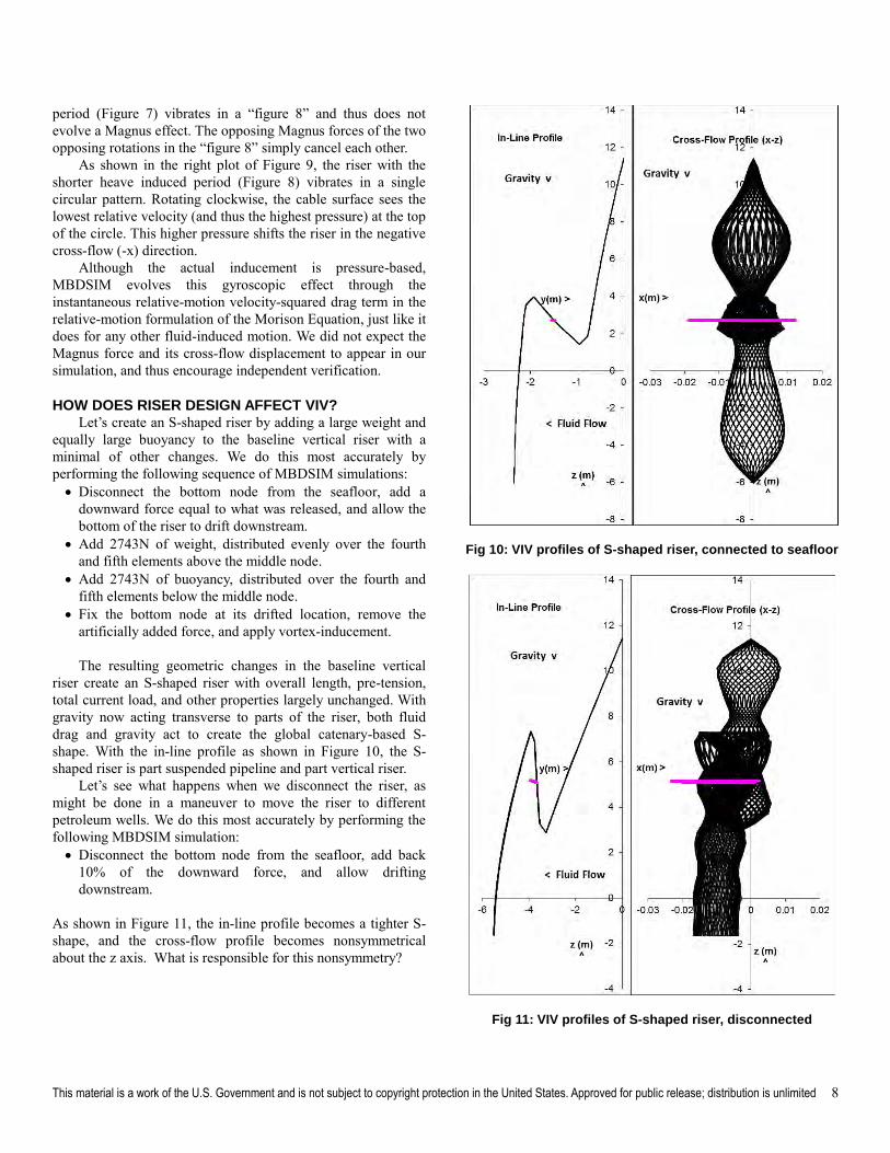
HOW DOES RISER DESIGN AFFECT VIV? Let’s create an S-shaped riser by adding a large weight and
equally large buoyancy to the baseline vertical riser with a minimal of other changes. We do this most accurately by performing the following sequence of MBDSIM simulations: Disconnect the bottom node from the seafloor, add a
downward force equal to what was released, and allow thebottom of the riser to drift downstream.
Add 2743N of weight, distributed evenly over the fourthand fifth elements above the middle node.
Add 2743N of buoyancy, distributed over the fourth andfifth elements below the middle node.
Fix the bottom node at its drifted location, remove theartificially added force, and apply vortex-inducement.
The resulting geometric changes in the baseline vertical riser create an S-shaped riser with overall length, pre-tension, total current load, and other properties largely unchanged. With gravity now acting transverse to parts of the riser, both fluid drag and gravity act to create the global catenary-based S-shape. With the in-line profile as shown in Figure 10, the S-shaped riser is part suspended pipeline and part vertical riser.
Let’s see what happens when we disconnect the riser, as might be done in a maneuver to move the riser to different petroleum wells. We do this most accurately by performing the following MBDSIM simulation: Disconnect the bottom node from the seafloor, add back
10% of the downward force, and allow driftingdownstream.
As shown in Figure 11, the in-line profile becomes a tighter S-shape, and the cross-flow profile becomes nonsymmetrical about the z axis. What is responsible for this nonsymmetry?
Fig 10: VIV profiles of S-shaped riser, connected to seafloor
Fig 11: VIV profiles of S-shaped riser, disconnected
This material is a work of the U.S. Government and is not subject to copyright protection in the United States. Approved for public release; distribution is unlimited 9
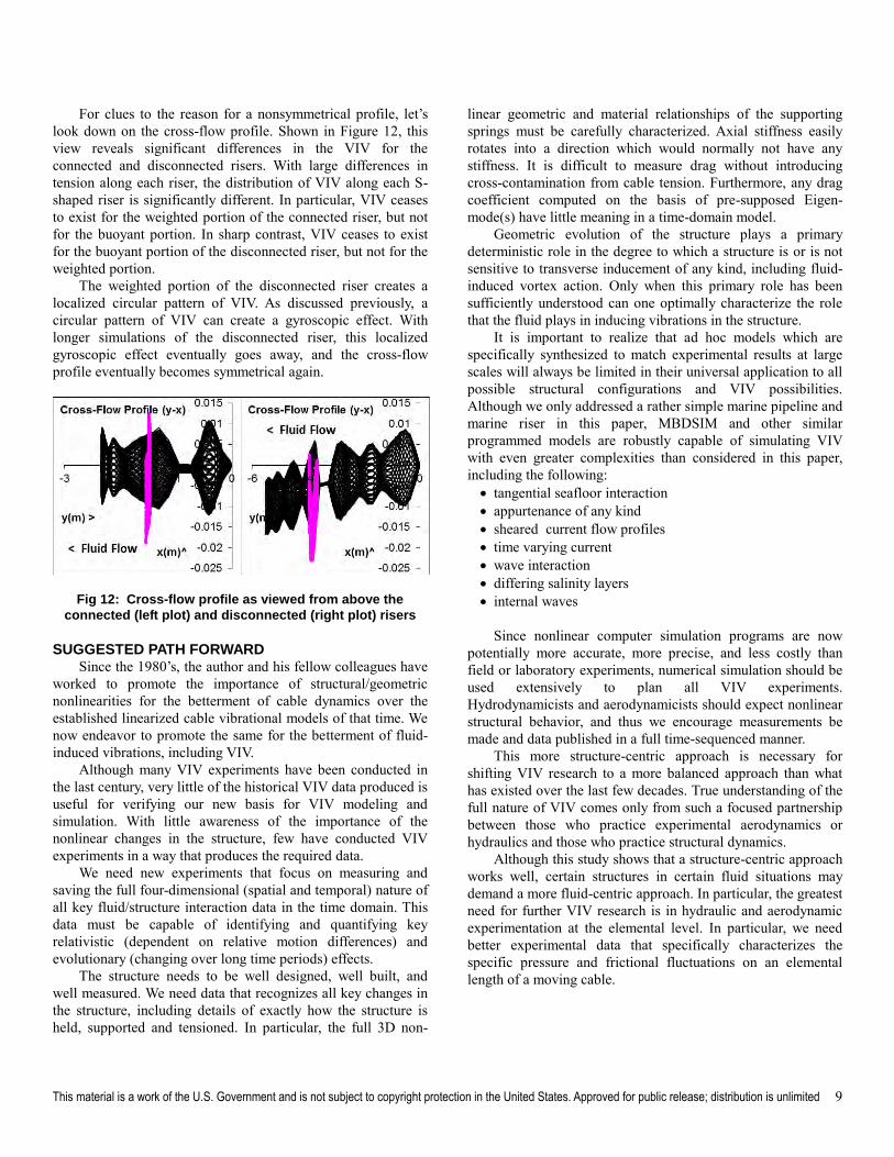
For clues to the reason for a nonsymmetrical profile, let’s look down on the cross-flow profile. Shown in Figure 12, this view reveals significant differences in the VIV for the connected and disconnected risers. With large differences in tension along each riser, the distribution of VIV along each S-shaped riser is significantly different. In particular, VIV ceases to exist for the weighted portion of the connected riser, but not for the buoyant portion. In sharp contrast, VIV ceases to exist for the buoyant portion of the disconnected riser, but not for the weighted portion.
The weighted portion of the disconnected riser creates a localized circular pattern of VIV. As discussed previously, a circular pattern of VIV can create a gyroscopic effect. With longer simulations of the disconnected riser, this localized gyroscopic effect eventually goes away, and the cross-flow profile eventually becomes symmetrical again.
Fig 12: Cross-flow profile as viewed from above the
connected (left plot) and disconnected (right plot) risers
SUGGESTED PATH FORWARD Since the 1980’s, the author and his fellow colleagues have
worked to promote the importance of structural/geometric nonlinearities for the betterment of cable dynamics over the established linearized cable vibrational models of that time. We now endeavor to promote the same for the betterment of fluid-induced vibrations, including VIV.
Although many VIV experiments have been conducted in the last century, very little of the historical VIV data produced is useful for verifying our new basis for VIV modeling and simulation. With little awareness of the importance of the nonlinear changes in the structure, few have conducted VIV experiments in a way that produces the required data.
We need new experiments that focus on measuring and saving the full four-dimensional (spatial and temporal) nature of all key fluid/structure interaction data in the time domain. This data must be capable of identifying and quantifying key relativistic (dependent on relative motion differences) and evolutionary (changing over long time periods) effects.
The structure needs to be well designed, well built, and well measured. We need data that recognizes all key changes in the structure, including details of exactly how the structure is held, supported and tensioned. In particular, the full 3D non-
linear geometric and material relationships of the supporting springs must be carefully characterized. Axial stiffness easily rotates into a direction which would normally not have any stiffness. It is difficult to measure drag without introducing cross-contamination from cable tension. Furthermore, any drag coefficient computed on the basis of pre-supposed Eigen-mode(s) have little meaning in a time-domain model.
Geometric evolution of the structure plays a primary deterministic role in the degree to which a structure is or is not sensitive to transverse inducement of any kind, including fluid-induced vortex action. Only when this primary role has been sufficiently understood can one optimally characterize the role that the fluid plays in inducing vibrations in the structure.
It is important to realize that ad hoc models which are specifically synthesized to match experimental results at large scales will always be limited in their universal application to all possible structural configurations and VIV possibilities. Although we only addressed a rather simple marine pipeline and marine riser in this paper, MBDSIM and other similar programmed models are robustly capable of simulating VIV with even greater complexities than considered in this paper, including the following: tangential seafloor interaction appurtenance of any kind sheared current flow profiles time varying current wave interaction differing salinity layers internal waves
Since nonlinear computer simulation programs are now potentially more accurate, more precise, and less costly than field or laboratory experiments, numerical simulation should be used extensively to plan all VIV experiments. Hydrodynamicists and aerodynamicists should expect nonlinear structural behavior, and thus we encourage measurements be made and data published in a full time-sequenced manner.
This more structure-centric approach is necessary for shifting VIV research to a more balanced approach than what has existed over the last few decades. True understanding of the full nature of VIV comes only from such a focused partnership between those who practice experimental aerodynamics or hydraulics and those who practice structural dynamics.
Although this study shows that a structure-centric approach works well, certain structures in certain fluid situations may demand a more fluid-centric approach. In particular, the greatest need for further VIV research is in hydraulic and aerodynamic experimentation at the elemental level. In particular, we need better experimental data that specifically characterizes the specific pressure and frictional fluctuations on an elemental length of a moving cable.
This material is a work of the U.S. Government and is not subject to copyright protection in the United States. Approved for public release; distribution is unlimited 10
CONCLUSION In this paper, we reviewed the basic mechanics of VIV for
a horizontally suspended marine pipeline and a simple vertical marine riser. We then investigated how VIV changed with respect to several specific design choices, which eventually led to an S-shaped marine riser. VIV along S-shaped risers was shown to be an intricate combination of a horizontally suspended pipeline and a vertically oriented riser.
We used a physics-based structural model married with a drag-based empirical representation of vortex inducement that is physically consistent with the friction and pressure variations created by real vortex streams. The results of this study reinforced the following basic mechanical concepts of VIV in a marine riser: Gravity and fluid drag evolve a 3D shape to a riser. This shape creates specific directional flexibilities. These flexibilities allow for specific VIV opportunities. These lead to natural VIV effects such as period-doubling. Tension and end conditions play a vital role in VIV. VIV can be shown to increase with increasing fluid drag.
A structure-centric approach to simulations of fluid/structure interaction has been shown to offer a useful new perspective for better understanding the natural balance between the structure’s “upstream” ability to control all vibrations and the fluid’s “downstream” ability to form the vortices that induce structural vibration.
ACKNOWLEDGMENTS Warren Bartel, Steve Karnoski, Dr. Paul Palo, Dr. Ray
Chiou, Nathan Finch, Peter Fanning and other fellow cable analysts provided valuable insights and reviews. Professors Noel Perkins at University of Michigan, Jean-Louis Lilien at the University of Liege, and David Shields at the University of Nevada Las Vegas posed the key initial challenges that eventually led to the findings in this paper. Dr. Kim Vandiver provided support with data from the Castine Field Experiment.
REFERENCES Argyris J, Faust G & Haase M (1994). An Exploration of
Chaos, Volume II, Texts on Computational Mechanics, North Holland: Elsevier.
Blevins RD (1990). Flow-Induced Vibration, New York: Van Nostrand Reinhold.
Chakrabarti SK (1987). Hydrodynamics of Offshore
Structures, Berlin: Springer-Verlag. Diana G, Belloli, M, Giappino S, Muggiasca S (2008)
“Vortex-Induced Vibrations at High Reynolds Numbers” BBAA
VI International Colloquium on Bluff Bodies Aerodynamics &
Applications, Milano, Italy. Grant R, Litton R, Finn L, Maher J & Lambrakos K (2000).
“Highly Compliant Rigid Risers: Field Test Benchmarking a Time Domain VIV Algorithm” Proceedings, OTC-11995-MS, Offshore Technology Conference, Houston.
Lugt HJ (1983). Vortex Flow in Nature and Technology, New York: John Wiley & Sons.
Palo PA, Meggit DJ & Nordell WJ (1983). “Dynamic Cable Analysis Models” OTC 4500, Proceedings- Offshore
Technology Conference, Houston. Srinil N (2010). “Multi-mode Interactions in Vortex-
Induced Vibrations of Flexible Curved/Straight Structures with Geometric Nonlinearities” Journal Fluids & Structures 26(7-8).
Vandiver JK & Jong JY (1987). “The Relationship between In-Line & Cross-Flow Vortex-Induced Vibration of Cylinders,” Journal of Fluids and Structures, Vol. 1.
Webster RL (1977). “Finite Element Analysis of Deep Sea Moors and Cable Systems”, Reprint 3033, ASCE Annual
Convention, San Francisco. Zasso A, Belloli M, Giappino S, Muggiasca S (2006). “On
the Pressure and Force Field on a Circular Cylinder Oscillating in the Lock-in Region at Sub-Critical Reynolds Number,”
ASME Pressure Vessels and Piping Division Conf, Vancouver. Zueck RF & Shields DR (1986). “Differences in Mooring
Models for Deep Water Semisubmersible Motion Simulation,” OMAE Specialty Symposium on Offshore and Arctic Frontiers, ASME, New Orleans.
Zueck RF & Powell G (1995). “Stable Numerical Solver for Cable Structures,” Intl Symposium on Cable Dynamics, AIM, Liege, Belgium.
Zueck, RF (1996). Local/Global Approach to Nonlinear
Simulation of Compliant Marine Structures, PhD Dissertation, SESM, Civil Engineering, University of California, Berkeley.
Zueck RF (1997). “Desired Model for Fluid Inducement,” Workshop on Flow/Wave-Structure Interactions, Brown University, Providence RI.
Zueck RF (2007). “Nonlinear Geometric Effects -- A Key to Vortex-Induced Vibrations,” Intl Symposium on Cable
Dynamics, AIM, Vienna. Zueck RF (2008). “Role of Geometrically Evolving
Mechanics in Vortex-Induced Vibrations,” Symposium on
Mechanics of Slender Structures, University of Maryland Baltimore County.
Zueck RF (2009). “Nonlinear Dynamics of Strings and Cable Stays,” Intl Symposium on Cable Dynamics, AIM, Paris.
Zueck RF (2011). “The Vital Mechanics of Vortex-Induced Vibrations,” Intl Offshore & Polar Engineering Conf, Maui, HI.
Zueck RF & Palo PA (2014). “The Key Mechanics Principles for Vortex-Induced Vibrations,” Intl Conf on Ocean,
Offshore & Arctic Engineering, ASME, San Francisco. Zueck RF (2015). “Basic Mechanics of Vortex-Induced
Vibrations in Marine Risers,” Intl Conf on Ocean, Offshore &
Arctic Engineering, ASME, St. John’s, Newfoundland.
Recommended