Embed Size (px)
Citation preview
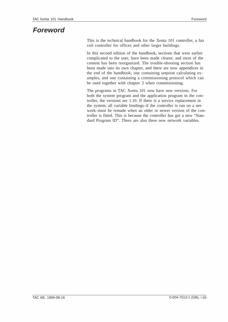
Zone ControllerTAC Xenta 101Handbook
0-004-7513-1 (GB), 1999-08-16
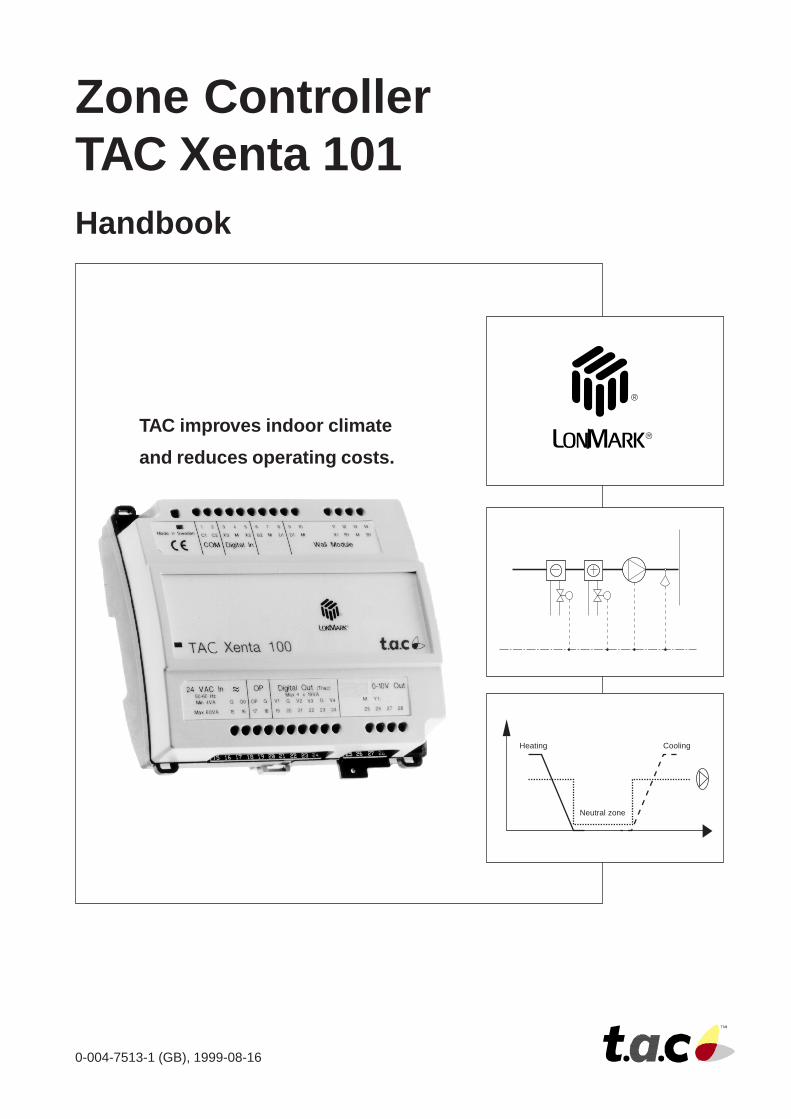
Heating Cooling
Neutral zone
TAC improves indoor climate
and reduces operating costs.

TAC AB, 1999-08-16
TAC Xenta 101 Handbook Foreword
0-004-7513-1 (GB), i (ii)
ForewordThis is the technical handbook for the Xenta 101 controller, a fancoil controller for offices and other larger buildings.
In this second edition of the handbook, sections that were earliercomplicated to the user, have been made clearer, and most of thecontent has been reorganized. The trouble-shooting section hasbeen made into its own chapter, and there are now appendices inthe end of the handbook; one containing setpoint calculating ex-amples, and one containing a commissioning protocol which canbe used together with chapter 3 when commissioning.
The programs in TAC Xenta 101 now have new versions. Forboth the system program and the application program in the con-troller, the versions are 1.10. If there is a service replacement inthe system, all variable bindings–if the controller is run on a net-work–must be remade when an older or newer version of the con-troller is fitted. This is because the controller has got a new “Stan-dard Program ID”. There are also three new network variables.
TAC AB, 1999-08-16
TAC Xenta 101 Handbook Foreword
ii (ii), 0-004-7513-1 (GB)
Revisions listPart number Comment Editor Date
0-004-7514-0 First edition. KRRO 1997-09-110-004-7514-1 Second edition. New versions (1.10) of system- och application programs. SUWA 1999-08-16
Copyright © 1999 TAC AB
This document contains proprietary information of TAC AB and is made available solely to those who operate and TAC AB equipment. Disclosure, reproductionor use of either the documents or the information contained herein for any other purpose is strictly prohibited.
Echelon®, Lon®, LonWorks®, LonTalk®, Neuron®, 3150®, och LonMark® are registered trademarks of Echelon Corporation in the United States and othercountries. Xenta® and Vista® are registered trademarks of TAC AB.
TAC AB reserves the right to make changes or additions to material as necessary.
TAC AB, 1999-08-16
TAC Xenta 101 Handbook Contents
0-004-7513-1 (GB), 1 (2)
Zone controller TAC Xenta 101Handbook
Reservations for changes.
Contents
1 Introduction ................................................................................................................. 1:11.1 The content of the handbook ............................................................................................................. 1:1
1.2 Documentation ................................................................................................................................... 1:2
1.3 Terminology....................................................................................................................................... 1:3
2 The zone controller TAC Xenta 101 .......................................................................... 2:12.1 General ............................................................................................................................................... 2:1
2.2 Wall modules ...................................................................................................................................... 2:3
2.3 Applications ........................................................................................................................................ 2:4
2.3.1 General ................................................................................................................................................ 2:42.3.2 The zone controller TAC Xenta 101-1VF ........................................................................................... 2:42.3.3 The zone controller TAC Xenta 101-1VFC ......................................................................................... 2:52.3.4 The zone controller TAC Xenta 101-2VF ........................................................................................... 2:52.3.5 The zone controller TAC Xenta 101-2VFC ......................................................................................... 2:6
3 Installation .................................................................................................................... 3:13.1 Mechanical installation .................................................................................................................... 3:1
3.1.1 Fitting .................................................................................................................................................. 3:13.2 Electrical installation ........................................................................................................................ 3:3
3.2.1 General ................................................................................................................................................ 3:33.2.2 Wiring of TAC Xenta 101-1VF ........................................................................................................... 3:53.2.3 Wiring of TAC Xenta 101-1VFC ........................................................................................................ 3:63.2.4 Wiring of TAC Xenta 101-2VF ........................................................................................................... 3:73.2.5 Wiring of TAC Xenta 101-2VFC ........................................................................................................ 3:83.3 Commissioning ................................................................................................................................... 3:9
3.3.1 General ................................................................................................................................................ 3:93.3.2 Node status .......................................................................................................................................... 3:93.3.3 Configuration parameters (nci’s) .......................................................................................................3:103.3.4 Network installation ..........................................................................................................................3:103.3.5 Network variable binding .................................................................................................................3:113.3.6 Function test ......................................................................................................................................3:11
4 Configuration parameters .......................................................................................... 4:14.1 Basic parameters ............................................................................................................................... 4:2
4.2 Other configuration parameters ....................................................................................................... 4:3
TAC AB, 1999-08-16
TAC Xenta 101 Handbook Contents
2 (2), 0-004-7513-1 (GB)
5 Functional description ................................................................................................. 5:15.1 General ............................................................................................................................................... 5:1
5.2 The controller’s basic functions ........................................................................................................ 5:2
5.2.1 Operation modes ................................................................................................................................. 5:25.2.2 Forcing the controller .......................................................................................................................... 5:45.2.3 Measuring zone temperature ............................................................................................................... 5:55.2.4 Setpoint calculation ............................................................................................................................ 5:55.2.5 Control sequence with one valve output (controllers 1VF and 1VFC) .............................................. 5:75.2.6 Control sequence with two valve outputs (controllers 2VF and 2VFC) ............................................. 5:85.2.7 Fan control .......................................................................................................................................... 5:95.3 More about functions .......................................................................................................................5:10
5.3.1 Heating and cooling control .............................................................................................................5:105.3.2 Cascade control .................................................................................................................................5:115.3.3 Window contact .................................................................................................................................5:125.3.4 Occupancy sensor ..............................................................................................................................5:125.3.5 Minimum value for heating valve ....................................................................................................5:135.3.6 Alarm .................................................................................................................................................5:145.3.7 Frost protection .................................................................................................................................5:145.3.8 Master/slave operation ......................................................................................................................5:15
6 Trouble-shooting .......................................................................................................... 6:16.1 General ............................................................................................................................................... 6:1
6.2 Inputs and outputs (nvi/nvo’s)............................................................................................................ 6:2
6.3 Problems and solutions ...................................................................................................................... 6:3
7 Technical data .............................................................................................................. 7:17.1 Technical data .................................................................................................................................... 7:1
7.2 Dimensions .......................................................................................................................................... 7:3
7.2.1 With semi-protection ........................................................................................................................... 7:37.2.2 Without semi-protection ..................................................................................................................... 7:3
8 Communication ........................................................................................................... 8:18.1 General ............................................................................................................................................... 8:1
8.2 Normal settings and power on ........................................................................................................... 8:1
8.3 Monitoring network variables, Heartbeat ....................................................................................... 8:2
8.4 Not accepted values ............................................................................................................................ 8:3
8.5 The node object .................................................................................................................................. 8:3
8.5.1 The node object’s inputs (nvi) ............................................................................................................. 8:38.5.2 The node object’s outputs (nvo) .......................................................................................................... 8:48.5.3 The node object’s configuration parameters (nci) .............................................................................. 8:48.6 The controller object ......................................................................................................................... 8:4
8.6.1 The controller object’s inputs (nvi) ..................................................................................................... 8:68.6.2 The controller object’s outputs (nvo) .................................................................................................. 8:78.6.3 The controller object’s configuration parameters (nci) ....................................................................... 8:8
Appendix A: Setpoint calculation ............................................................................... App A:1Appendix B: Commissioning protocol ....................................................................... App B:1Index ................................................................................................................................. Reg:1Reply
TAC AB, 1999-08-16 0-004-7513-1 (GB), 1:1 (4)
TAC Xenta 101 Handbook About this handbook
1 Introduction
1.1 The content of the handbook• Chapter 1 Introduction,
gives an overview over the structure of this handbook,additional information about the product, and has a shortterminology section.
• Chapter 2 The zone controller TAC Xenta 101,describes, among other things, the wall module, and briefly thecontroller’s functions. It shows applications for the fourdifferent types of TAC Xenta 101.
• Chapter 3 Installation,contains instructions on mechanical and electrical installationof the controller, and instructions on commissioning andnetwork installation.
• Chapter 4 Configuration parameters,describes the setting of the zone controller’s configurationparameters.
• Chapter 5 Functional description,gives detailed information about the zone controller’s basicfunctions, operating modes, and other functions.
• Chapter 6 Trouble-shooting during operation andcommissioning,contains trouble-shooting measures you can use to find and fixpossible faults in the system.
• Chapter 7 Technical data,lists all technical data and dimensions for TAC Xenta 101.
• Chapter 8 Communication,describes the zone controller’s communication with other unitsvia the network by means of network variables.
• Appendix A, Setpoint calculationcontains calculating examples for the setpoint calculation inchapter 5.
• Appendix B, Commissioning protocolcontains a commissioning protocol, which can be usedtogether with chapter 3 during installation and commissioning.
1:2 (4), 0-004-7513-1 (GB) TAC AB, 1999-08-16
TAC Xenta 101 Handbook About this handbook
• Index and Reply form,are in the end of the handbook. Use the index to make yoursearch for information easier, and the reply form to let us knowwhether there is something wrong or unclear in this handbook.
1.2 Documentation
Enclosed documentation
TAC Xenta 101 is delivered with an installation instruction foreach of the following types of controllers:
• TAC Xenta 101-1VF,Installation instruction, part number 0FL-3853
• TAC Xenta 101-1VFC,Installation instruction, part number 0FL-3854
• TAC Xenta 101-2VF,Installation instruction, part number 0FL-3855
• TAC Xenta 101-2VFC,Installation instruction, part number 0FL-3856
Other documentation
There is additional information about TAC Xenta 101 in thefollowing documents:
• Data sheet for TAC Xenta 101-1VF,part number 0-003-1743
• Data sheet for TAC Xenta 101-1VFC,part number 0-003-1388
• Data sheet for TAC Xenta 101-2VF,part number 0-003-1605
• Data sheet for TAC Xenta 101-2VFC,part number 0-003-1608
• Data sheet for ZS 101–ZS 105,part number 0-003-1661. Here the wall modules are described.
• TAC Xenta Network Guide,part number 0-004-7460. Here you can find additional infor-mation on network installation.
• TAC Xenta OP Handbook,part number 0-004-7506. Here you find information on how touse TAC Xenta OP together with TAC Xenta 101 and the wallmodules.
• TAC Xenta, Zone System Guidelinespart number 0-004-7637. Here you find information on howthe zone system is built with TAC Xenta-components.
TAC AB, 1999-08-16 0-004-7513-1 (GB), 1:3 (4)
TAC Xenta 101 Handbook About this handbook
• TAC Xenta 101 Handbook,part number 0-004-7513-0. Here you find information on theearlier version of the zone controller.
All the above mentioned documents can be found on the internetat www.tac.se or can be ordered from your nearest TAC servicepoint.
1.3 TerminologyIn this handbook there are some abbreviations and terms whichare specific for the zone controller’s applications and networkcommunication. Therefore, the most common terms have beengathered, together with a short explanation, in the list below.
neuron .................communication processor with built-in protocol
node.....................communication unit on the network
SNVT ...................Standard Network Variable Type
nvixxx ..................variable which gets its value from another uniton the network
nvoxxx .................variable which value is sent out to another uniton the network
ncixxx ..................configuration parameter; variable which gets itsvalue from another unit on the network andwhich keeps it during a power failure
service pin ...........function which can be used during installationon the network
wink .....................confirmation that the connection to a controllervia the network is working (a light emmittingdiode is lit for appr. 15 seconds)
LNS ......................LonWork Network Services. System tool forinstallation, configuration and maintenance ofLonWorks network
1:4 (4), 0-004-7513-1 (GB) TAC AB, 1999-08-16
TAC Xenta 101 Handbook About this handbook
Blank page
TAC AB, 1999-08-16 0-004-7513-1 (GB), 2:1 (6)
TAC Xenta 101 Handbook The zone controller TAC Xenta 101
2 The zone controller TAC Xenta 101
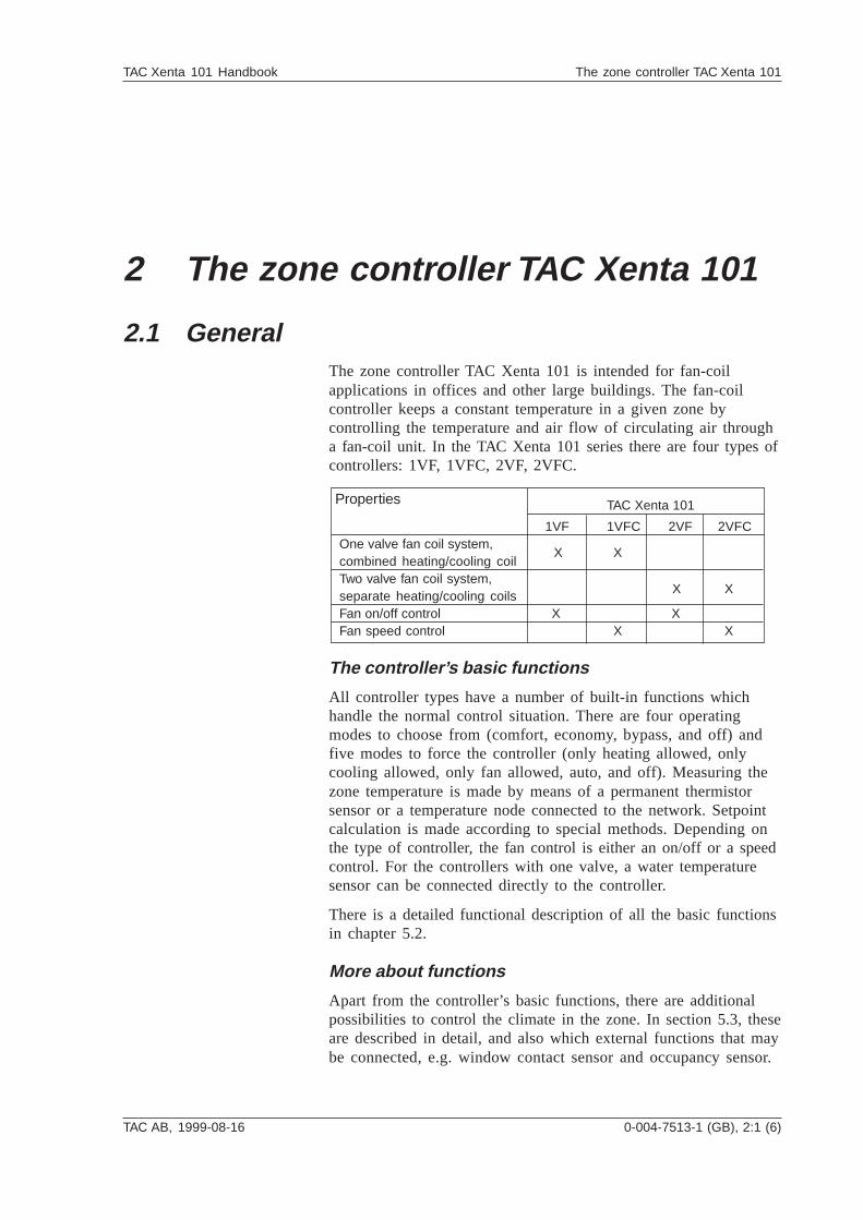
2.1 GeneralThe zone controller TAC Xenta 101 is intended for fan-coilapplications in offices and other large buildings. The fan-coilcontroller keeps a constant temperature in a given zone bycontrolling the temperature and air flow of circulating air througha fan-coil unit. In the TAC Xenta 101 series there are four types ofcontrollers: 1VF, 1VFC, 2VF, 2VFC.
The controller’s basic functions
All controller types have a number of built-in functions whichhandle the normal control situation. There are four operatingmodes to choose from (comfort, economy, bypass, and off) andfive modes to force the controller (only heating allowed, onlycooling allowed, only fan allowed, auto, and off). Measuring thezone temperature is made by means of a permanent thermistorsensor or a temperature node connected to the network. Setpointcalculation is made according to special methods. Depending onthe type of controller, the fan control is either an on/off or a speedcontrol. For the controllers with one valve, a water temperaturesensor can be connected directly to the controller.
There is a detailed functional description of all the basic functionsin chapter 5.2.
More about functions
Apart from the controller’s basic functions, there are additionalpossibilities to control the climate in the zone. In section 5.3, theseare described in detail, and also which external functions that maybe connected, e.g. window contact sensor and occupancy sensor.
TAC Xenta 101
1VF 1VFC 2VF 2VFCOne valve fan coil system,combined heating/cooling coilTwo valve fan coil system,separate heating/cooling coilsFan on/off control X XFan speed control X X
Properties
X X
X X
2:2 (6), 0-004-7513-1 (GB) TAC AB, 1999-08-16
TAC Xenta 101 Handbook The zone controller TAC Xenta 101
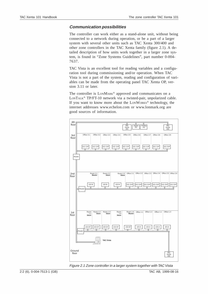
Communication possibilities
The controller can work either as a stand-alone unit, without beingconnected to a network during operation, or be a part of a largersystem with several other units such as TAC Xenta 300/400 andother zone controllers in the TAC Xenta family (figure 2.1). A de-tailed description of how units work together in a larger zone sys-tem, is found in “Zone Systems Guidelines”, part number 0-004-7637.
TAC Vista is an excellent tool for reading variables and a configu-ration tool during commissioning and/or operation. When TACVista is not a part of the system, reading and configuration of vari-ables can be made from the operating panel TAC Xenta OP, ver-sion 3.11 or later.
The controller is LONMARK® approved and communicates on aLONTALK ® TP/FT-10 network via a twisted-pair, unpolarized cable.If you want to know more about the LONWORKS® technology, theinternet addresses www.echelon.com or www.lonmark.org aregood sources of information.
Figure 2.1 Zone controller in a larger system together with TAC Vista
103-A103-A103-A103-A102-EF102-EF102-EF102-EF102-EF
101-2VF101-2VF101-2VF101-2VF101-2VF101-2VF102-B 102-B102-B
101-1VF 101-2VF101-1VF101-1VF101-1VF101-1VF101-1VF101-1VF101-1VF
AnalogI/O
DigitalI/O
TACXenta300
Router
Router
Router
TACXenta400
TACXenta400
3rdfloor
Office 3:1 Office 3:2 Office 3:3 Office 3:4 Office 3:5 Office 3:6 Office 3:7 Office 3:8 Office 3:9
2ndfloor
Office 2:1 Office 2:2 Office 2:3 Office 2:4 Office 2:5 Office 2:6Room 2:1Master
Room 2:2Slave
Room 2:3Slave
TAC Vista
1stfloor
Room1:1
Slave
Room 1:2Slave
Room1:4
Slave
Room 1:3Slave
Room 1:5Master
Office 1:1 Office 1:2 Office 1:3 Office 1:4
4thfloor
Groundfloor
TAC AB, 1999-08-16 0-004-7513-1 (GB), 2:3 (6)
TAC Xenta 101 Handbook The zone controller TAC Xenta 101
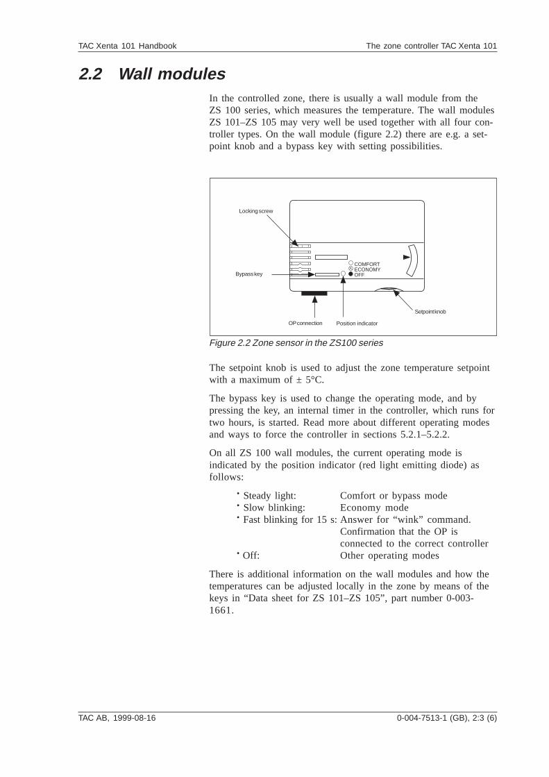
2.2 Wall modulesIn the controlled zone, there is usually a wall module from theZS 100 series, which measures the temperature. The wall modulesZS 101–ZS 105 may very well be used together with all four con-troller types. On the wall module (figure 2.2) there are e.g. a set-point knob and a bypass key with setting possibilities.
The setpoint knob is used to adjust the zone temperature setpointwith a maximum of ± 5°C.
The bypass key is used to change the operating mode, and bypressing the key, an internal timer in the controller, which runs fortwo hours, is started. Read more about different operating modesand ways to force the controller in sections 5.2.1–5.2.2.
On all ZS 100 wall modules, the current operating mode isindicated by the position indicator (red light emitting diode) asfollows:
· Steady light: Comfort or bypass mode· Slow blinking: Economy mode· Fast blinking for 15 s:Answer for “wink” command.
Confirmation that the OP isconnected to the correct controller
· Off: Other operating modes
There is additional information on the wall modules and how thetemperatures can be adjusted locally in the zone by means of thekeys in “Data sheet for ZS 101–ZS 105”, part number 0-003-1661.
Figure 2.2 Zone sensor in the ZS100 series
OP connection Position indicator
COMFORTECONOMYOFF
Setpoint knob
Bypass key
Locking screw
2:4 (6), 0-004-7513-1 (GB) TAC AB, 1999-08-16
TAC Xenta 101 Handbook The zone controller TAC Xenta 101
2.3 Applications
2.3.1 General
To all Xenta 101 controllers,
• a window contact sensor to stop the heating and cooling func-tions, should a window be opened, can be connected. An occu-pancy sensor can detect the presence of a person in the controlledzone and change the controller from economy to comfort mode.
• the fan is off in economy and off mode, if there is not a need forheating or cooling. In those cases, the fan is running.
• if you connect a water temperature sensor, you can have anautomatic change between heating/cooling (only for controllerwith a combined heating/cooling coil).
• there is also a possibility of an even better control, if youconnect a discharge air temperature sensor. When such a sensor isconnected, the controller controls the discharge air temperatureand the zone temperature in cascade.
The window contact sensor, occupancy sensor, and cascadecontrol of the discharge air and zone temperatures, are describedin detail in section 5.3.2–5.3.4.
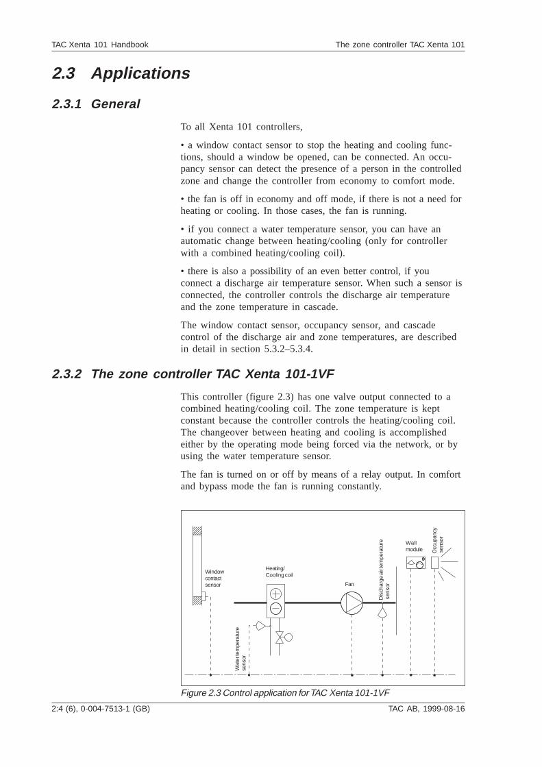
2.3.2 The zone controller TAC Xenta 101-1VF
This controller (figure 2.3) has one valve output connected to acombined heating/cooling coil. The zone temperature is keptconstant because the controller controls the heating/cooling coil.The changeover between heating and cooling is accomplishedeither by the operating mode being forced via the network, or byusing the water temperature sensor.
The fan is turned on or off by means of a relay output. In comfortand bypass mode the fan is running constantly.
Windowcontactsensor
Heating/Cooling coil
Wat
er te
mpe
ratu
rese
nsor
Fan
Wallmodule O
ccup
ancy
sen
sor
Dis
char
ge a
ir te
mpe
ratu
re s
enso
r
Figure 2.3 Control application for TAC Xenta 101-1VF
TAC AB, 1999-08-16 0-004-7513-1 (GB), 2:5 (6)
TAC Xenta 101 Handbook The zone controller TAC Xenta 101
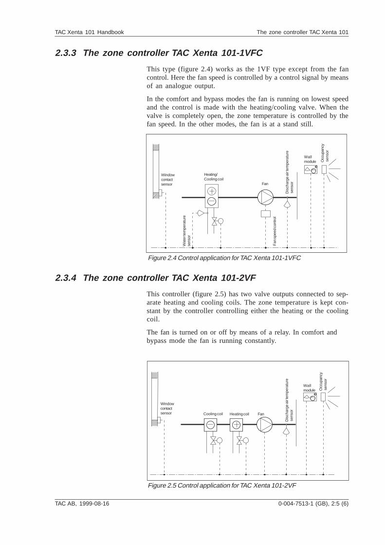
2.3.3 The zone controller TAC Xenta 101-1VFC
This type (figure 2.4) works as the 1VF type except from the fancontrol. Here the fan speed is controlled by a control signal by meansof an analogue output.
In the comfort and bypass modes the fan is running on lowest speedand the control is made with the heating/cooling valve. When thevalve is completely open, the zone temperature is controlled by thefan speed. In the other modes, the fan is at a stand still.
Windowcontactsensor
Heating/Cooling coil
Wallmodule O
ccup
ancy
sen
sor
Dis
char
ge a
ir te
mpe
ratu
re s
enso
r
Wat
er te
mpe
ratu
rese
nsor
Fan
spe
ed c
ontr
ol
Figure 2.4 Control application for TAC Xenta 101-1VFC
Fan
2.3.4 The zone controller TAC Xenta 101-2VF
This controller (figure 2.5) has two valve outputs connected to sep-arate heating and cooling coils. The zone temperature is kept con-stant by the controller controlling either the heating or the coolingcoil.
The fan is turned on or off by means of a relay. In comfort andbypass mode the fan is running constantly.
Occ
upan
cy s
enso
r
Windowcontactsensor
Wallmodule
Cooling coil Heating coil
Dis
char
ge a
ir te
mpe
ratu
re s
enso
r
Fan
Figure 2.5 Control application for TAC Xenta 101-2VF
2:6 (6), 0-004-7513-1 (GB) TAC AB, 1999-08-16
TAC Xenta 101 Handbook The zone controller TAC Xenta 101
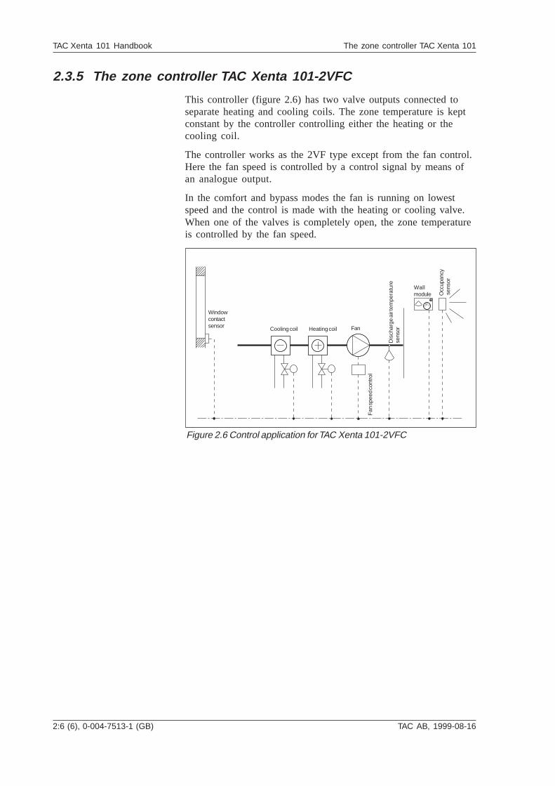
2.3.5 The zone controller TAC Xenta 101-2VFC
This controller (figure 2.6) has two valve outputs connected toseparate heating and cooling coils. The zone temperature is keptconstant by the controller controlling either the heating or thecooling coil.
The controller works as the 2VF type except from the fan control.Here the fan speed is controlled by a control signal by means ofan analogue output.
In the comfort and bypass modes the fan is running on lowestspeed and the control is made with the heating or cooling valve.When one of the valves is completely open, the zone temperatureis controlled by the fan speed.
Windowcontactsensor Cooling coil Heating coil Fan
Fan
spe
ed c
ontr
ol
Dis
char
ge a
ir te
mpe
ratu
rese
nsor
Wallmodule O
ccup
ancy
sen
sor
Figure 2.6 Control application for TAC Xenta 101-2VFC
TAC AB, 1999-08-16 0-004-7513-1 (GB), 3:1 (12)
TAC Xenta 101 Handbook Installation
3 Installation
3.1 Mechanical installation
3.1.1 Fitting
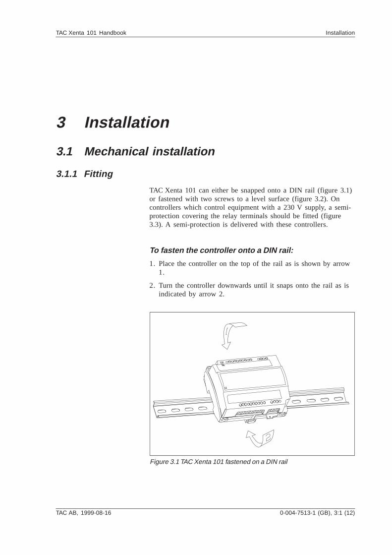
TAC Xenta 101 can either be snapped onto a DIN rail (figure 3.1)or fastened with two screws to a level surface (figure 3.2). Oncontrollers which control equipment with a 230 V supply, a semi-protection covering the relay terminals should be fitted (figure3.3). A semi-protection is delivered with these controllers.
To fasten the controller onto a DIN rail:
1. Place the controller on the top of the rail as is shown by arrow1.
2. Turn the controller downwards until it snaps onto the rail as isindicated by arrow 2.
Figure 3.1 TAC Xenta 101 fastened on a DIN rail
3:2 (12), 0-004-7513-1 (GB) TAC AB, 1999-08-16
TAC Xenta 101 Handbook Installation
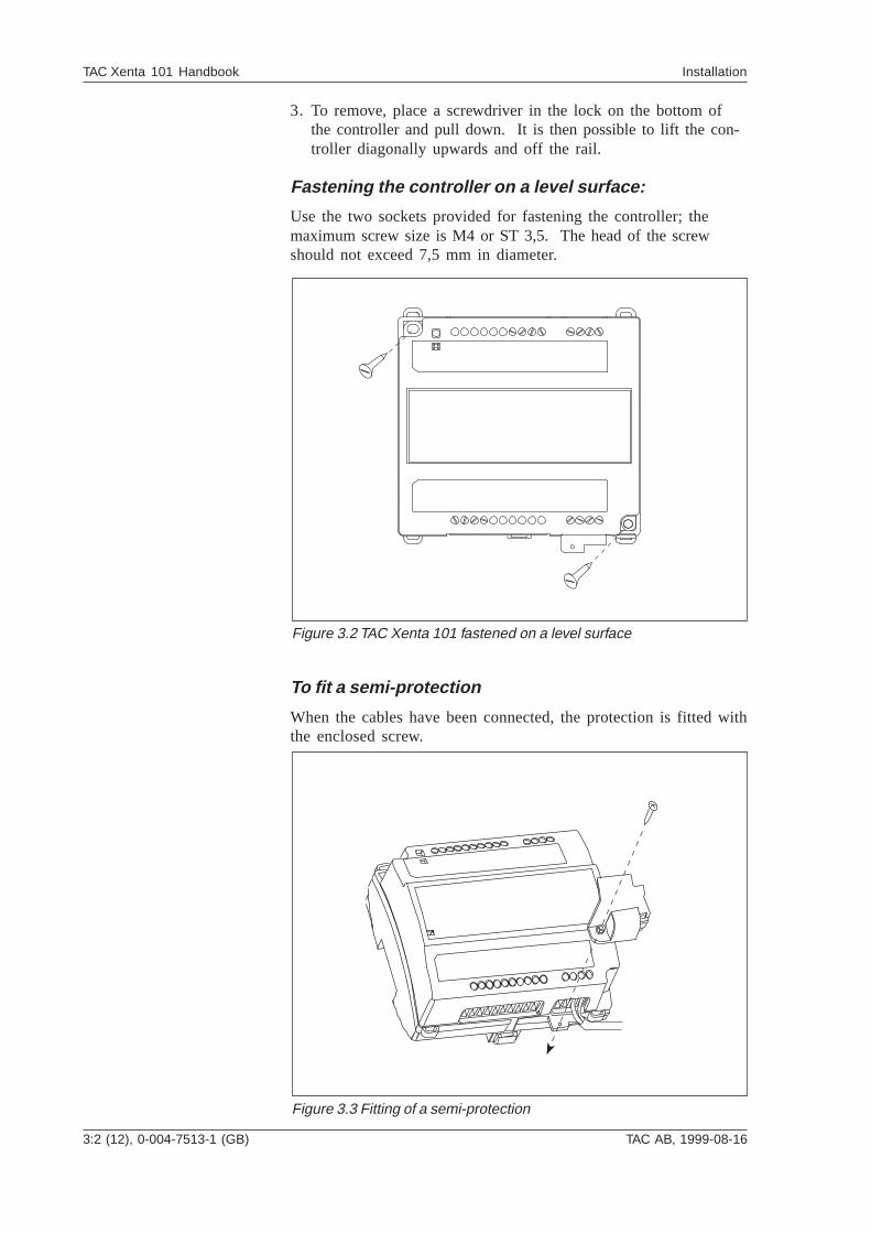
3. To remove, place a screwdriver in the lock on the bottom ofthe controller and pull down. It is then possible to lift the con-troller diagonally upwards and off the rail.
Fastening the controller on a level surface:
Use the two sockets provided for fastening the controller; themaximum screw size is M4 or ST 3,5. The head of the screwshould not exceed 7,5 mm in diameter.
Figure 3.2 TAC Xenta 101 fastened on a level surface
To fit a semi-protection
When the cables have been connected, the protection is fitted withthe enclosed screw.
Figure 3.3 Fitting of a semi-protection
TAC AB, 1999-08-16 0-004-7513-1 (GB), 3:3 (12)
TAC Xenta 101 Handbook Installation
3.2 Electrical installation
3.2.1 General
Warning! All 230 V supply cables must beinstalled by authorised electricians.
1. Each controller or group of controllers must be fitted with max.6 A fuses.
2. Secure the cables to the controller by means of clamps orsimilar, to limit their mobility.
3. Strap wires or shrink-to-fit tubes must be fitted to make surethat loose 230 V cables cannot get in contact with ELV cables–supply or signal cables–and vice versa.
4. It must be simple to break the power supply for the controlleror for the complete installation.
5. Connect U1 and M with a jumper when no water temperaturesensor is connected to the terminals.
6. When several Xenta controllers are supplied from a commontransformer, it is important that all G’s are connected with eachother and that all G0’s are connected with each other. Theymust not be interchanged. An important exception: G0 on thewall module should not be connected with the other G0’s.Instead it should be connected to the terminal OP on thecontroller.
At the transformer, G0 should be connected to protective earth.This is to get an grounding point for interference diversion.
7. Connect the two M terminals to the wall module to get thespecified measuring accuracy for the room temperature.
Safety standard
Transformers supplying the controller must comply to the safetystandard EN 60 742 or any other relevant safety standard for ELV,24 V AC. When equipment with a power supply of its own is con-nected, this power supply must also comply with this norm.
Cable lengths
For information on communication cable lengths, see TAC XentaNetwork Guide, part number 0-004-7460. For all other cables,maximum length is 30 m and min. area is 0,7 mm2 .
!!
3:4 (12), 0-004-7513-1 (GB) TAC AB, 1999-08-16
TAC Xenta 101 Handbook Installation
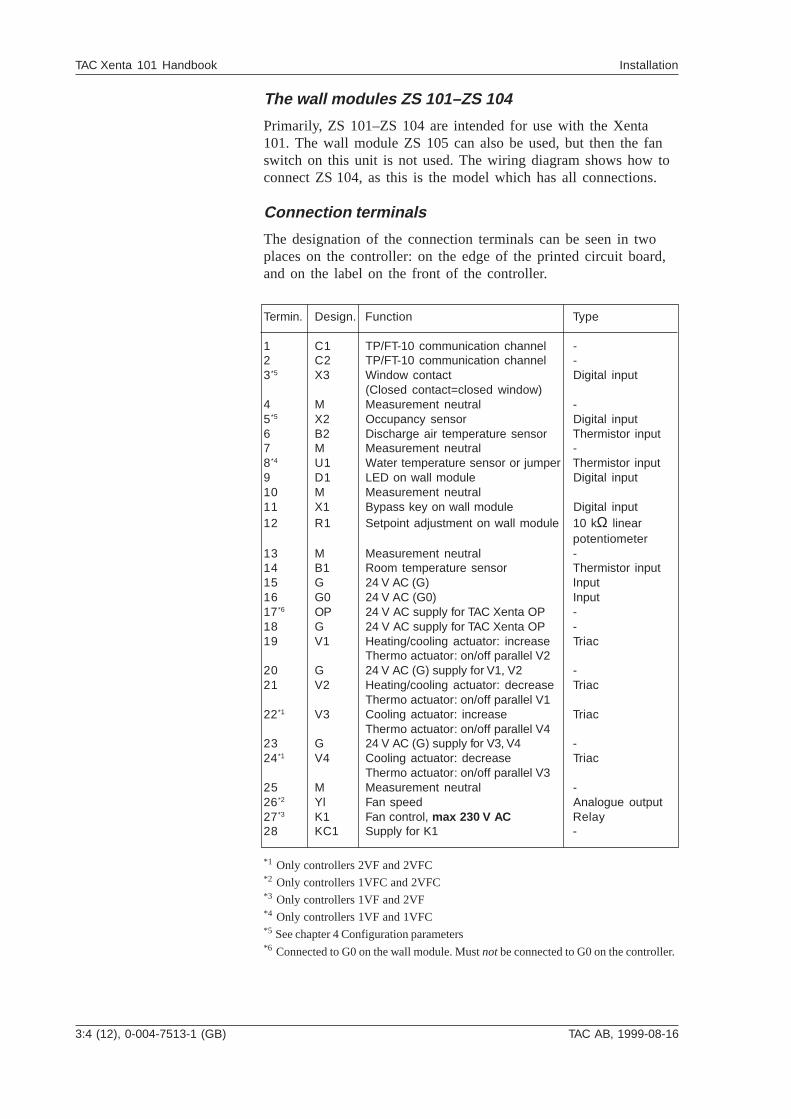
The wall modules ZS 101–ZS 104
Primarily, ZS 101–ZS 104 are intended for use with the Xenta101. The wall module ZS 105 can also be used, but then the fanswitch on this unit is not used. The wiring diagram shows how toconnect ZS 104, as this is the model which has all connections.
Connection terminals
The designation of the connection terminals can be seen in twoplaces on the controller: on the edge of the printed circuit board,and on the label on the front of the controller.
Termin. Design. Function Type
1 C1 TP/FT-10 communication channel -2 C2 TP/FT-10 communication channel -3*5 X3 Window contact Digital input
(Closed contact=closed window)4 M Measurement neutral -5*5 X2 Occupancy sensor Digital input6 B2 Discharge air temperature sensor Thermistor input7 M Measurement neutral -8*4 U1 Water temperature sensor or jumper Thermistor input9 D1 LED on wall module Digital input10 M Measurement neutral11 X1 Bypass key on wall module Digital input12 R1 Setpoint adjustment on wall module 10 kΩ linear
potentiometer13 M Measurement neutral -14 B1 Room temperature sensor Thermistor input15 G 24 V AC (G) Input16 G0 24 V AC (G0) Input17*6 OP 24 V AC supply for TAC Xenta OP -18 G 24 V AC supply for TAC Xenta OP -19 V1 Heating/cooling actuator: increase Triac
Thermo actuator: on/off parallel V220 G 24 V AC (G) supply for V1, V2 -21 V2 Heating/cooling actuator: decrease Triac
Thermo actuator: on/off parallel V122*1 V3 Cooling actuator: increase Triac
Thermo actuator: on/off parallel V423 G 24 V AC (G) supply for V3, V4 -24*1 V4 Cooling actuator: decrease Triac
Thermo actuator: on/off parallel V325 M Measurement neutral -26*2 Yl Fan speed Analogue output27*3 K1 Fan control, max 230 V AC Relay28 KC1 Supply for K1 -
*1 Only controllers 2VF and 2VFC*2 Only controllers 1VFC and 2VFC*3 Only controllers 1VF and 2VF*4 Only controllers 1VF and 1VFC*5 See chapter 4 Configuration parameters*6 Connected to G0 on the wall module. Must not be connected to G0 on the controller.
TAC AB, 1999-08-16 0-004-7513-1 (GB), 3:5 (12)
TAC Xenta 101 Handbook Installation
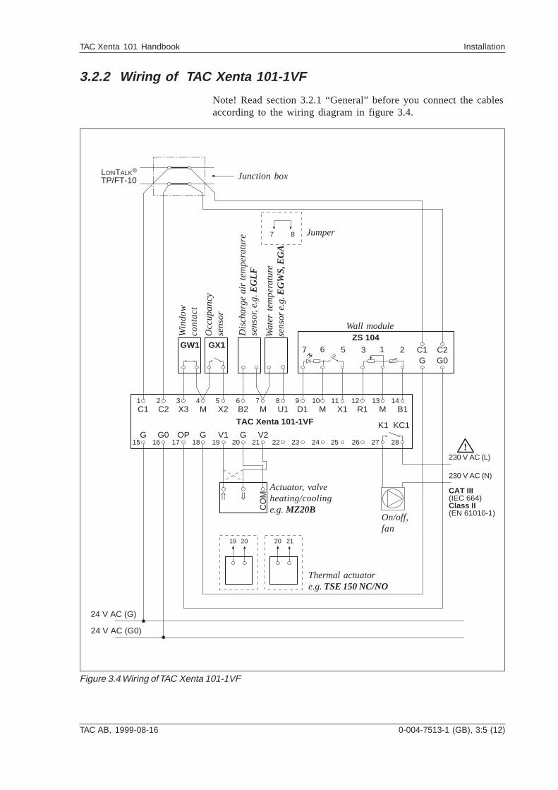
3.2.2 Wiring of TAC Xenta 101-1VF
Note! Read section 3.2.1 “General” before you connect the cablesaccording to the wiring diagram in figure 3.4.
G G0
C2 X3 M M MM X1 R1 B1
OP V1
D1C1
GG
1 2 3 4 5 6 7 8 9 10 11 12 13 14
15 16 17 18 19 20 21 22 23 24 25 26
X2
V2
TAC Xenta 101-1VF
GW1 GX1
24 V AC (G)
24 V AC (G0)
LONTALK®
TP/FT-10
B2
Ý ß
CO
M
U1
7 8
KC1
27 28
K1
!230 V AC (L)
CAT III(IEC 664)Class II(EN 61010-1)
230 V AC (N)
19 20 2120
ZS 104
C2C1G G0
6 217 5 3
Figure 3.4 Wiring of TAC Xenta 101-1VF
Win
do
wco
nta
ct
Occ
up
an
cyse
nso
r
Dis
cha
rge
air
te
mp
era
ture
sen
sor,
e.g
. EG
LF
Wa
ter
tem
pe
ratu
rese
nso
r e
.g. EG
WS
, EG
A
Wall module
Actuator, valveheating/coolinge.g. MZ20B
On/off,fan
Junction box
Jumper
Thermal actuatore.g. TSE 150 NC/NO
3:6 (12), 0-004-7513-1 (GB) TAC AB, 1999-08-16
TAC Xenta 101 Handbook Installation
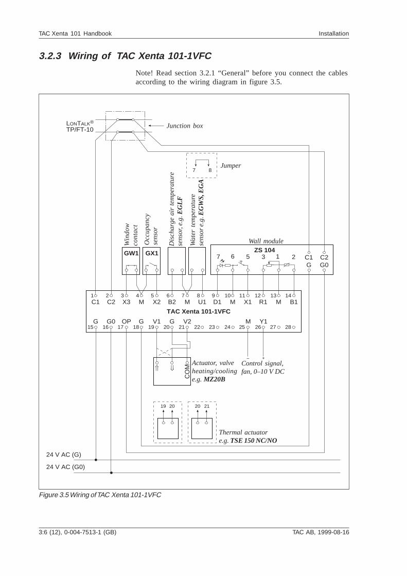
3.2.3 Wiring of TAC Xenta 101-1VFC
Note! Read section 3.2.1 “General” before you connect the cablesaccording to the wiring diagram in figure 3.5.
G G0
C2 X3 M M MM X1 R1 B1
OP V1
D1C1
GG
1 2 3 4 5 6 7 8 9 10 11 12 13 14
15 16 17 18 19 20 21 22 23 24 25 26 27 28
X2
MV2
TAC Xenta 101-1VFC
ZS 104C2C1
G G02
GW1 GX1
24 V AC (G)
24 V AC (G0)
LONTALK®
TP/FT-10
B2
Ý ß
CO
M
Y1
+
U1
7 8
6 17 5 3
19 20 2120
Figure 3.5 Wiring of TAC Xenta 101-1VFC
Control signal,fan, 0–10 V DC
Win
do
wco
nta
ct
Occ
up
an
cyse
nso
r
Dis
cha
rge
air
te
mp
era
ture
sen
sor,
e.g
. EG
LF
Wa
ter
tem
pe
ratu
rese
nso
r e
.g. EG
WS
, EG
A
Wall module
Actuator, valveheating/coolinge.g. MZ20B
Junction box
Jumper
Thermal actuatore.g. TSE 150 NC/NO
TAC AB, 1999-08-16 0-004-7513-1 (GB), 3:7 (12)
TAC Xenta 101 Handbook Installation
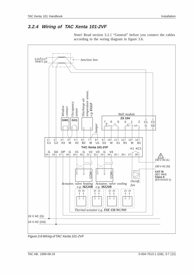
3.2.4 Wiring of TAC Xenta 101-2VF
Note! Read section 3.2.1 “General” before you connect the cablesaccording to the wiring diagram in figure 3.6.
Figure 3.6 Wiring of TAC Xenta 101-2VF
G G0
C2 X3 M M MM X1 R1 B1
OP V1
D1C1
GG G
1 2 3 4 5 6 7 8 9 10 11 12 13 14
15 16 17 18 19 20 21 22 23 24 25 26
X2
V2
TAC Xenta 101-2VF
ZS 104C2C1
G G02GW1 GX1
LONTALK®
TP/FT-10
B2
Ý ß
CO
M Ý ß
CO
M
V3 V4
24 V AC (G)
24 V AC (G0)
U1
6 17 5 3
KC1
27 28
K1
!230 V AC (L)
CAT III(IEC 664)Class II(EN 61010-1)
230 V AC (N)
19 20 2120 22 23 2423
Jum
pe
r
Win
do
wco
nta
ct
Occ
up
an
cyse
nso
r
Dis
cha
rge
air
tem
pe
ratu
re s
en
sor,
e.g
. EG
LF
Wall module
Actuator, valve heatinge.g. MZ20B
On/off,fan
Junction box
Actuator, valve coolinge.g. MZ20B
Thermal actuator e.g. TSE 150 NC/NO
3:8 (12), 0-004-7513-1 (GB) TAC AB, 1999-08-16
TAC Xenta 101 Handbook Installation
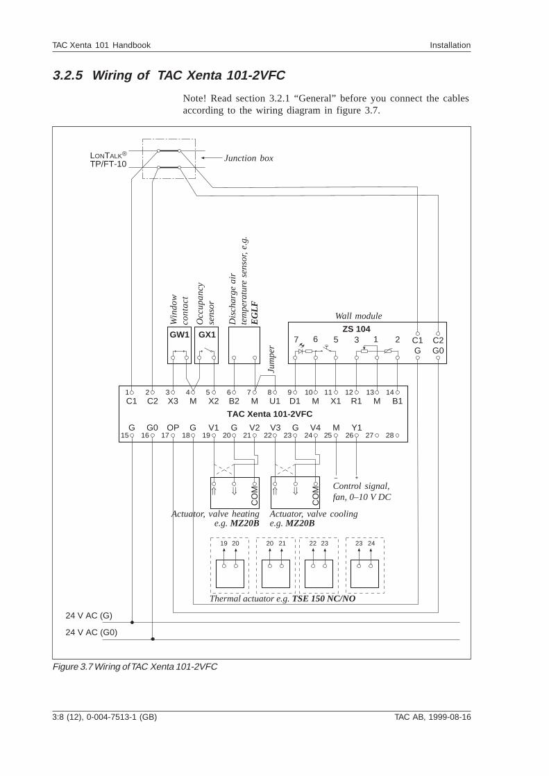
3.2.5 Wiring of TAC Xenta 101-2VFC
Note! Read section 3.2.1 “General” before you connect the cablesaccording to the wiring diagram in figure 3.7.
Figure 3.7 Wiring of TAC Xenta 101-2VFC
G G0
C2 X3 M M MM X1 R1 B1
OP V1
D1C1
GG G
1 2 3 4 5 6 7 8 9 10 11 12 13 14
15 16 17 18 19 20 21 22 23 24 25 26 27 28
X2
MV2
TAC Xenta 101-2VFC
ZS 104C2C1
G G02GW1 GX1
LONTALK®
TP/FT-10
B2
Ý ß
CO
M Ý ß
CO
M
V3 V4 Y1
+
24 V AC (G)
24 V AC (G0)
U1
6 17 5 3
19 20 2120 22 23 2423
Jum
pe
r
Control signal,fan, 0–10 V DC
Win
do
wco
nta
ct
Occ
up
an
cyse
nso
r
Dis
cha
rge
air
tem
pe
ratu
re s
en
sor,
e.g
.E
GLF
Wall module
Actuator, valve heatinge.g. MZ20B
Junction box
Actuator, valve coolinge.g. MZ20B
Thermal actuator e.g. TSE 150 NC/NO

TAC AB, 1999-08-16 0-004-7513-1 (GB), 3:9 (12)
TAC Xenta 101 Handbook Installation
3.3 Commissioning
3.3.1 General
When the mechanical and electrical installation has been made,you can commission the controller. This means:
· Installing the controller on the network, set node status andgive it an address.
· Set the controller's configuration parameters.· Bind network variables.· Test the function.
When it comes to commisioning of complete zone systems, readthe manual “TAC Xenta - Zone Systems Guideline”. Here you willfind a short description of what to do and when to do it.
In short: you could use TAC Xenta OP for setting the basic para-meters. Use a network management tool or TAC Vista for commis-sioning the controller on the network and do the rest of the com-missioning.
When TAC Xenta 100 will be used stand-alone, this is how:
1. Set node status to “Configured” with TAC Xenta OP.2. Set the basic parameters with TAC Xenta OP.3. Set the other parameters and variables with TAC Xenta OP.
You could also use a network management tool for the commis-sioning.
3.3.2 Node status
The node status indicates which mode the controller is in, when itcomes to network configuration and program. The status can bechanged with TAC Vista (version 3.1 or later), network manage-ment tool, or, to some extent, TAC Xenta OP. The controller canbe in these states:
Unconfigured
The controller is in this state when delivered from the factory.Neither the program nor the network communication are running.The service light emitting diode is flashing.
The controller cannot work on a network in this state. To do so, itmust be in configured, online state, see below.
You cannot set configuration parameters or network variables inthis state.
3:10 (12), 0-004-7513-1 (GB) TAC AB, 1999-08-16
TAC Xenta 101 Handbook Installation
Configured, online
By means of TAC Xenta OP, TAC Vista or a network managementtool, the status can be changed to configured. Then, both theprogram and the network communication are running. The serviceLED is off. This is the normal state for a controller in operation.
Now the controller uses the address which it was given by the toolduring configuration. With TAC Xenta OP you cannot, however,set an address. Therefore all controllers get default addresses. Thismeans that such a TAC Xenta 100 cannot work on a network. Itcan only work stand-alone.
In this state you can set parameters and variables.
Configured, soft online
To get the controller into this state, you need a network manage-ment tool. The controller has a program and a networkconfiguration, but the program and the communication are at astandstill. The light emitting diode is off. If the controller is reset,it will go into configured, online.
Configured, hard online
To get the controller into this state, you need a network manage-ment tool. The controller has a program and a networkconfiguration, but the program and the communication are at astandstill. The light emitting diode is off. If the controller is reset,it will go remain in this state.
Without a program and not configured
This states indicates that there is something wrong with thecontroller. No program can be detected. The ligh emitting diode islit.
3.3.3 Configuration parameters (nci’s)
TAC Xenta 100 has a number of configuration parameters, whereyou can set how the controller should be working. Read aboutthem in chapter 4. There are also network variables whichcontrols the controller during operation.
Use the commissioning protocol in Appendix B to write downyour settings at commissioning. In chapter 8, there is informationon all parameters and variables, such as their index, acceptedvalues, normal values. There are detailed descriptions of theparameters and variables in chapter 4, 5, and 6.
TAC AB, 1999-08-16 0-004-7513-1 (GB), 3:11 (12)
TAC Xenta 101 Handbook Installation
3.3.4 Network installation
For network installation, you need either a network managementtool (LNS based or not) or TAC Vista. Examples of networkmanagement tools are MetraVision and ICELAN-G. Here you findbrief information on how this is made. You find more informationin “TAC Xenta, Guidelines for zone applications”.
The installation has two steps:
1. Feed information about the controllers’ unique neuron-ID intothe network management tool’s data base.
2. Let the network management tool install the controller on thenetwork. The controller will then also get an address.
There are two ways to feed the neuron-ID into the data base:
1. Manually feed the neuron-ID into the network managementtool. To make this easier you can use a bar code reader to readthe detachable ID-neuron label, which you find on everycontroller. It is suitable to gather these labels when you goaround and make the basic configuration, and stick them to aform, drawing or similar. In the manual “TAC Xenta, Guide-lines for zone applications” there is a form for this purpose.
2. Use the service pin function. You can only do this when thecontroller is connected to the network. On the controller thereis a service pin key in a hole in the upper left corner, atterminal C1. When you push this, the controller sends out itsneuron-ID. The network management tool can then read theneuron-ID from the network, to save it in its data base.
3.3.5 Network variable binding
How binding is done depends on which network managementtool is used. To get exact information, you should use the tool’sdocumentation. In “TAC Xenta Network manual“, there ishowevere a description of how network variables are bound withMetra Vision.
To bind network variables is not an issue when the controller isused in stand-alone operation.
3.3.6 Function test
You should also make sure that the control works as intended.
In chapter 5 all the controller’s functions are described.
In chapter 6 you find help, should a problem occur.
3:12 (12), 0-004-7513-1 (GB) TAC AB, 1999-08-16
TAC Xenta 101 Handbook Installation
Blank page
TAC AB, 1999-08-16 0-004-7513-1 (GB), 4:1 (4)
TAC Xenta 101 Handbook Configuration parameters
4 Configuration parametersAll communication with the controller is made by means ofnetwork variables. nci’s are used to configure the controller, nvi’scontrols the controller during operation, and nvo’s are outputvariables, which the controller sends out on the network. nci’s arenormally set during commissioning, and are not altered duringnormal operation (the parameters are stored in a special memory,and can be changed a maximum of 10 000 times). In chapter 8,there is detailed information on accepted values and normalvalues for all parameters. All configuration parameters havenormal values on delivery.
4:2 (4), 0-004-7513-1 (GB) TAC AB, 1999-08-16
TAC Xenta 101 Handbook Configuration parameters
4.1 Basic parameters
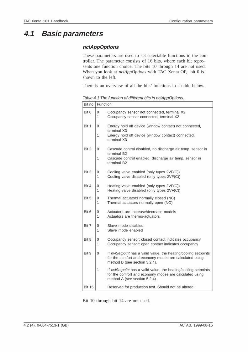
nciAppOptions
These parameters are used to set selectable functions in the con-troller. The parameter consists of 16 bits, where each bit repre-sents one function choice. The bits 10 through 14 are not used.When you look at nciAppOptions with TAC Xenta OP, bit 0 isshown to the left.
There is an overview of all the bits’ functions in a table below.
Bit no. Function
Bit 0 0 Occupancy sensor not connected, terminal X21 Occupancy sensor connected, terminal X2
Bit 1 0 Energy hold off device (window contact) not connected,terminal X3
1 Energy hold off device (window contact) connected,terminal X3
Bit 2 0 Cascade control disabled, no discharge air temp. sensor interminal B2
1 Cascade control enabled, discharge air temp. sensor interminal B2
Bit 3 0 Cooling valve enabled (only types 2VF(C))1 Cooling valve disabled (only types 2VF(C))
Bit 4 0 Heating valve enabled (only types 2VF(C))1 Heating valve disabled (only types 2VF(C))
Bit 5 0 Thermal actuators normally closed (NC)1 Thermal actuators normally open (NO)
Bit 6 0 Actuators are increase/decrease models1 Actuators are thermo-actuators
Bit 7 0 Slave mode disabled1 Slave mode enabled
Bit 8 0 Occupancy sensor: closed contact indicates occupancy1 Occupancy sensor: open contact indicates occupancy
Bit 9 0 If nviSetpoint has a valid value, the heating/cooling setpointsfor the comfort and economy modes are calculated usingmethod B (see section 5.2.4).
1 If nviSetpoint has a valid value, the heating/cooling setpointsfor the comfort and economy modes are calculated usingmethod A (see section 5.2.4).
Bit 15 Reserved for production test. Should not be altered!
Bit 10 through bit 14 are not used.
Table 4.1 The function of different bits in nciAppOptions.
TAC AB, 1999-08-16 0-004-7513-1 (GB), 4:3 (4)
TAC Xenta 101 Handbook Configuration parameters
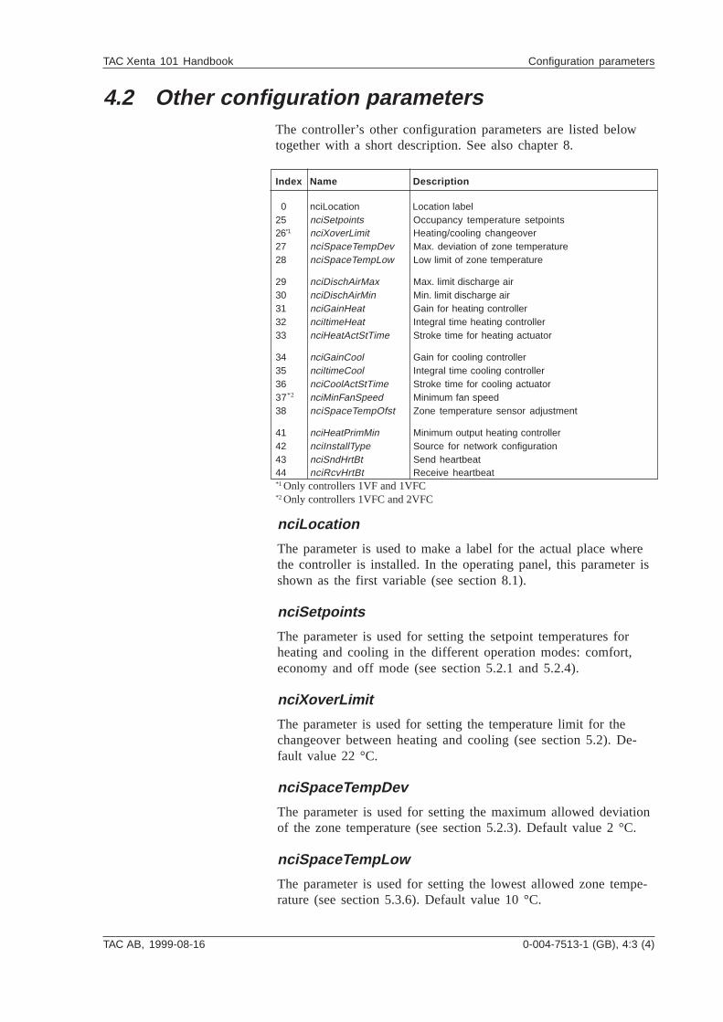
4.2 Other configuration parametersThe controller’s other configuration parameters are listed belowtogether with a short description. See also chapter 8.
Index Name Description
0 nciLocation Location label25 nciSetpoints Occupancy temperature setpoints26*1 nciXoverLimit Heating/cooling changeover27 nciSpaceTempDev Max. deviation of zone temperature28 nciSpaceTempLow Low limit of zone temperature
29 nciDischAirMax Max. limit discharge air30 nciDischAirMin Min. limit discharge air31 nciGainHeat Gain for heating controller32 nciItimeHeat Integral time heating controller33 nciHeatActStTime Stroke time for heating actuator
34 nciGainCool Gain for cooling controller35 nciItimeCool Integral time cooling controller36 nciCoolActStTime Stroke time for cooling actuator37*2 nciMinFanSpeed Minimum fan speed38 nciSpaceTempOfst Zone temperature sensor adjustment
41 nciHeatPrimMin Minimum output heating controller42 nciInstallType Source for network configuration43 nciSndHrtBt Send heartbeat44 nciRcvHrtBt Receive heartbeat*1 Only controllers 1VF and 1VFC*2 Only controllers 1VFC and 2VFC
nciLocation
The parameter is used to make a label for the actual place wherethe controller is installed. In the operating panel, this parameter isshown as the first variable (see section 8.1).
nciSetpoints
The parameter is used for setting the setpoint temperatures forheating and cooling in the different operation modes: comfort,economy and off mode (see section 5.2.1 and 5.2.4).
nciXoverLimit
The parameter is used for setting the temperature limit for thechangeover between heating and cooling (see section 5.2). De-fault value 22 °C.
nciSpaceTempDev
The parameter is used for setting the maximum allowed deviationof the zone temperature (see section 5.2.3). Default value 2 °C.
nciSpaceTempLow
The parameter is used for setting the lowest allowed zone tempe-rature (see section 5.3.6). Default value 10 °C.
4:4 (4), 0-004-7513-1 (GB) TAC AB, 1999-08-16
TAC Xenta 101 Handbook Configuration parameters
nciDischAirMax, nciDischAirMin
The parameters are used for setting the allowed maximum/mini-mum temperatures when using cascade control (see section 5.3.2).Default values 35/10 °C.
nciGainHeat, nciGainCool
The parameters are used for setting the gain for the heating/coo-ling controllers. Default value 25.
nciItimeHeat, nciItimeCool
The parameters are used for setting the I-time for the heating/coo-ling controllers. Default value 900 s (15 min).
nciHeatActStTime, nciCoolActStTime
The parameters are set according to the runtime of the actuator.
nciMinFanSpeed
The parameter is used for setting the minimum fan speed (see sec-tion 5.2.7).
nciSpaceTempOfst
The parameter is used for adjusting the temperature setpoints. De-fault value 0.0%.
nciHeatPrimMin
The parameter is used for setting the minimum value for the ope-ning of the heating valve (see section 5.3.5). Default value 0%.
nciInstallType
The parameter is only used during free-standing operation and isset to show that the node itself should define its address (seesection 8.5.3).
nciSndHrtBt
The parameter is used to decide how often the nvo’s, which aresent out on the network regularly, should be sent (see section 8.3).
nciRcvHrtBt
The parameter is used to decide the maximum time there can bebetween updating the nvi’s, for which the controller expects conti-nuous updating (see section 8.3).
TAC AB, 1999-08-16 0-004-7513-1 (GB), 5:1 (16)
TAC Xenta 101 Handbook Functional description
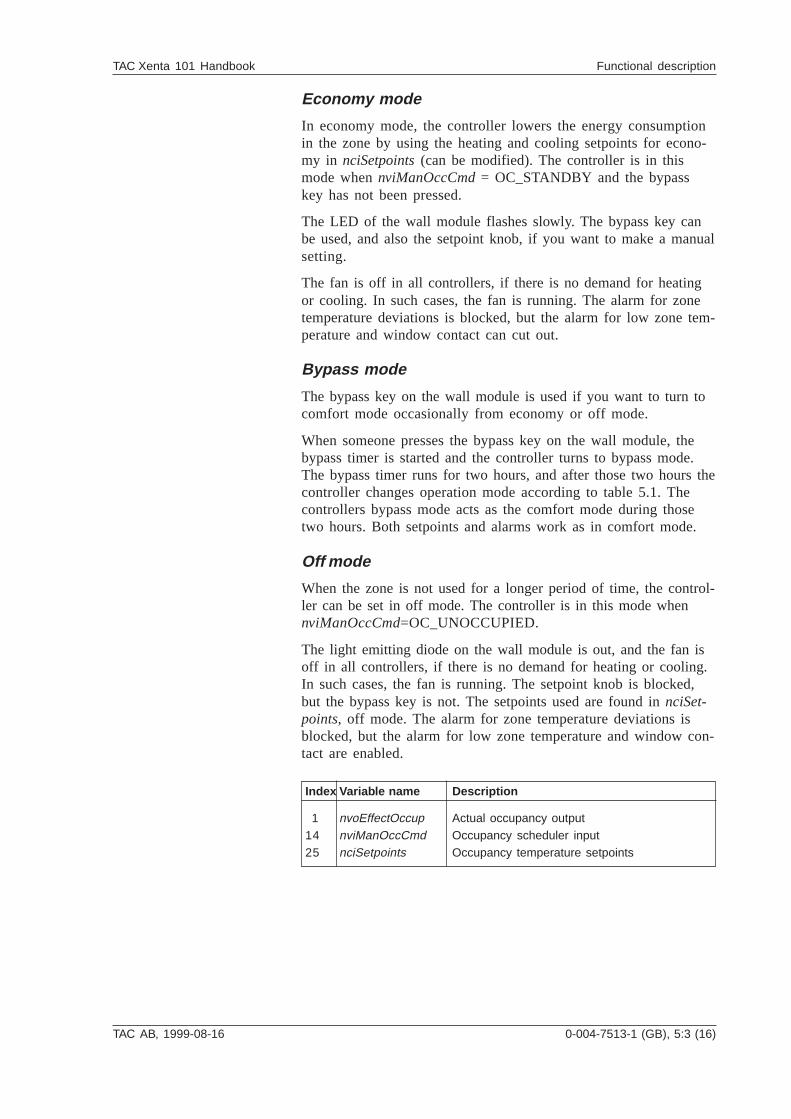
5 Functional description
5.1 GeneralThe controller’s function is determined by its node status (section3.3.2), different operations (section 5.2.1) and the ways to forcethe controller (section 5.2.2) for well-adapted zone temperaturcontrol. The controller has a built-in fan function, measures thezone temperature, and uses different methods to calculate set-points. Apart from the basic functions in chapter 5.2, the control-ler has a number of other possibilies to control the climate in thezone. There are information about these functions in chapter 5.3.
Each section in this chapter is ended with information on whichnetwork variables are used in the current control situation. If youneed details about the network variables’ characteristics, such asdefault values and accepted values, you find this in chapter 8.
5:2 (16), 0-004-7513-1 (GB) TAC AB, 1999-08-16
TAC Xenta 101 Handbook Functional description
5.2 The controller’s basic functions
5.2.1 Operation modes
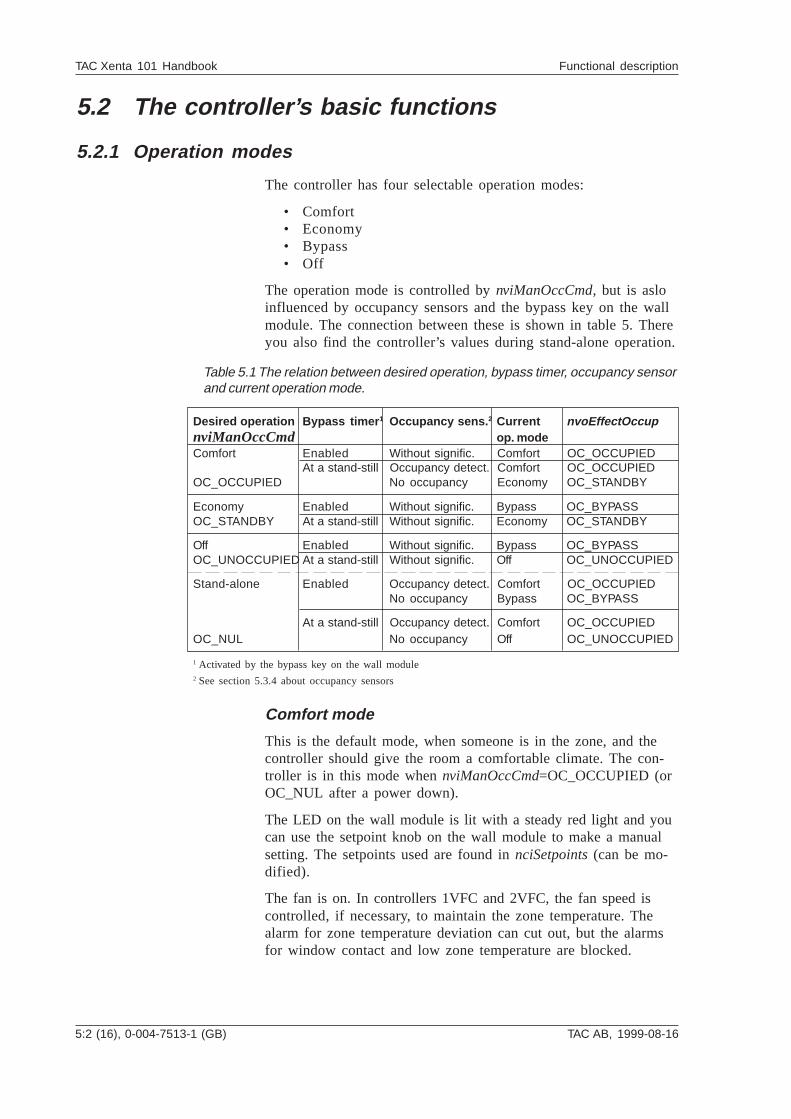
The controller has four selectable operation modes:
• Comfort• Economy• Bypass• Off
The operation mode is controlled by nviManOccCmd, but is asloinfluenced by occupancy sensors and the bypass key on the wallmodule. The connection between these is shown in table 5. Thereyou also find the controller’s values during stand-alone operation.
Desired operation Bypass timer 1 Occupancy sens. 2 Current nvoEffectOccupnviManOccCmd op. modeComfort Enabled Without signific. Comfort OC_OCCUPIED
At a stand-still Occupancy detect. Comfort OC_OCCUPIEDOC_OCCUPIED No occupancy Economy OC_STANDBY
Economy Enabled Without signific. Bypass OC_BYPASSOC_STANDBY At a stand-still Without signific. Economy OC_STANDBY
Off Enabled Without signific. Bypass OC_BYPASSOC_UNOCCUPIED At a stand-still Without signific. Off OC_UNOCCUPIED
Stand-alone Enabled Occupancy detect. Comfort OC_OCCUPIEDNo occupancy Bypass OC_BYPASS
At a stand-still Occupancy detect. Comfort OC_OCCUPIEDOC_NUL No occupancy Off OC_UNOCCUPIED
1 Activated by the bypass key on the wall module2 See section 5.3.4 about occupancy sensors
Comfort mode
This is the default mode, when someone is in the zone, and thecontroller should give the room a comfortable climate. The con-troller is in this mode when nviManOccCmd=OC_OCCUPIED (orOC_NUL after a power down).
The LED on the wall module is lit with a steady red light and youcan use the setpoint knob on the wall module to make a manualsetting. The setpoints used are found in nciSetpoints (can be mo-dified).
The fan is on. In controllers 1VFC and 2VFC, the fan speed iscontrolled, if necessary, to maintain the zone temperature. Thealarm for zone temperature deviation can cut out, but the alarmsfor window contact and low zone temperature are blocked.
Table 5.1 The relation between desired operation, bypass timer, occupancy sensorand current operation mode.
TAC AB, 1999-08-16 0-004-7513-1 (GB), 5:3 (16)
TAC Xenta 101 Handbook Functional description
Economy mode
In economy mode, the controller lowers the energy consumptionin the zone by using the heating and cooling setpoints for econo-my in nciSetpoints (can be modified). The controller is in thismode when nviManOccCmd = OC_STANDBY and the bypasskey has not been pressed.
The LED of the wall module flashes slowly. The bypass key canbe used, and also the setpoint knob, if you want to make a manualsetting.
The fan is off in all controllers, if there is no demand for heatingor cooling. In such cases, the fan is running. The alarm for zonetemperature deviations is blocked, but the alarm for low zone tem-perature and window contact can cut out.
Bypass mode
The bypass key on the wall module is used if you want to turn tocomfort mode occasionally from economy or off mode.
When someone presses the bypass key on the wall module, thebypass timer is started and the controller turns to bypass mode.The bypass timer runs for two hours, and after those two hours thecontroller changes operation mode according to table 5.1. Thecontrollers bypass mode acts as the comfort mode during thosetwo hours. Both setpoints and alarms work as in comfort mode.
Off mode
When the zone is not used for a longer period of time, the control-ler can be set in off mode. The controller is in this mode whennviManOccCmd=OC_UNOCCUPIED.
The light emitting diode on the wall module is out, and the fan isoff in all controllers, if there is no demand for heating or cooling.In such cases, the fan is running. The setpoint knob is blocked,but the bypass key is not. The setpoints used are found in nciSet-points, off mode. The alarm for zone temperature deviations isblocked, but the alarm for low zone temperature and window con-tact are enabled.
Index Variable name Description
1 nvoEffectOccup Actual occupancy output14 nviManOccCmd Occupancy scheduler input25 nciSetpoints Occupancy temperature setpoints
5:4 (16), 0-004-7513-1 (GB) TAC AB, 1999-08-16
TAC Xenta 101 Handbook Functional description
5.2.2 Forcing the controller
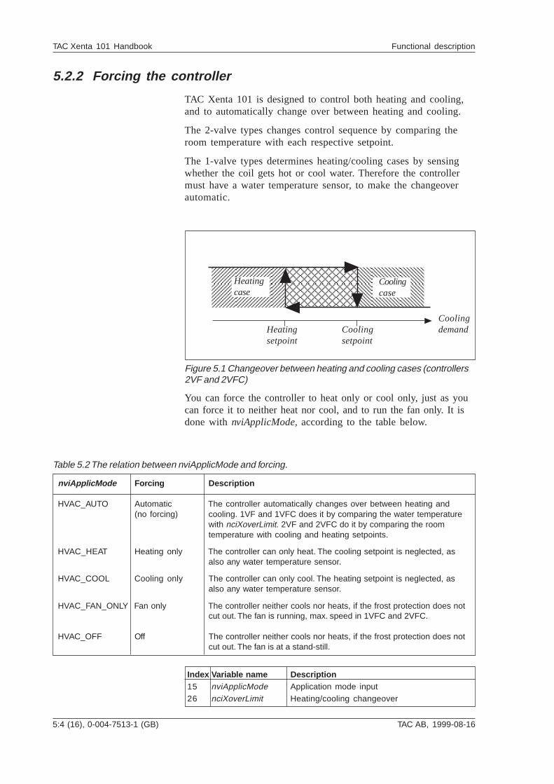
TAC Xenta 101 is designed to control both heating and cooling,and to automatically change over between heating and cooling.
The 2-valve types changes control sequence by comparing theroom temperature with each respective setpoint.
The 1-valve types determines heating/cooling cases by sensingwhether the coil gets hot or cool water. Therefore the controllermust have a water temperature sensor, to make the changeoverautomatic.
You can force the controller to heat only or cool only, just as youcan force it to neither heat nor cool, and to run the fan only. It isdone with nviApplicMode, according to the table below.
Figure 5.1 Changeover between heating and cooling cases (controllers2VF and 2VFC)
Coolingdemand
Coolingcase
Heatingcase
Heatingsetpoint
Coolingsetpoint
nviApplicMode Forcing Description
HVAC_AUTO Automatic The controller automatically changes over between heating and(no forcing) cooling. 1VF and 1VFC does it by comparing the water temperature
with nciXoverLimit. 2VF and 2VFC do it by comparing the roomtemperature with cooling and heating setpoints.
HVAC_HEAT Heating only The controller can only heat. The cooling setpoint is neglected, asalso any water temperature sensor.
HVAC_COOL Cooling only The controller can only cool. The heating setpoint is neglected, asalso any water temperature sensor.
HVAC_FAN_ONLY Fan only The controller neither cools nor heats, if the frost protection does notcut out. The fan is running, max. speed in 1VFC and 2VFC.
HVAC_OFF Off The controller neither cools nor heats, if the frost protection does notcut out. The fan is at a stand-still.
Table 5.2 The relation between nviApplicMode and forcing.
Index Variable name Description15 nviApplicMode Application mode input26 nciXoverLimit Heating/cooling changeover
TAC AB, 1999-08-16 0-004-7513-1 (GB), 5:5 (16)
TAC Xenta 101 Handbook Functional description
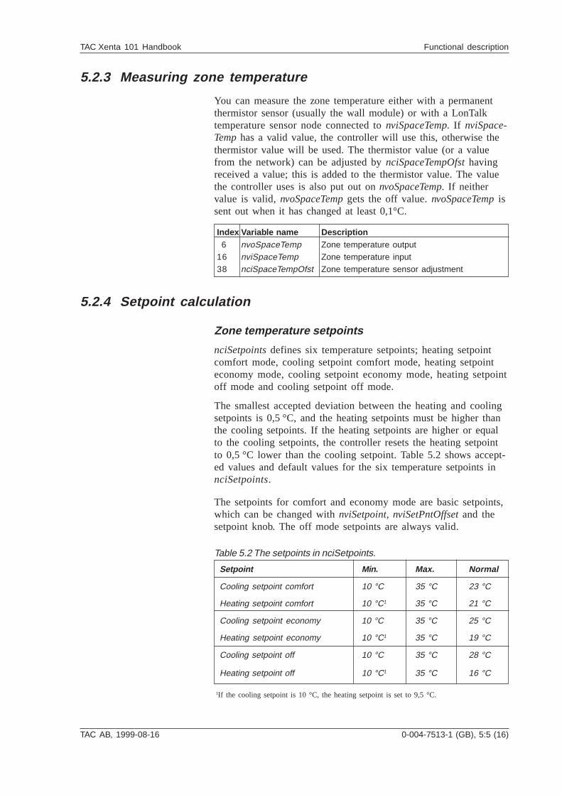
5.2.3 Measuring zone temperature
You can measure the zone temperature either with a permanentthermistor sensor (usually the wall module) or with a LonTalktemperature sensor node connected to nviSpaceTemp. If nviSpace-Temp has a valid value, the controller will use this, otherwise thethermistor value will be used. The thermistor value (or a valuefrom the network) can be adjusted by nciSpaceTempOfst havingreceived a value; this is added to the thermistor value. The valuethe controller uses is also put out on nvoSpaceTemp. If neithervalue is valid, nvoSpaceTemp gets the off value. nvoSpaceTemp issent out when it has changed at least 0,1°C.
Table 5.2 The setpoints in nciSetpoints.
Setpoint Min. Max. Normal
Cooling setpoint comfort 10 °C 35 °C 23 °C
Heating setpoint comfort 10 °C1 35 °C 21 °C
Cooling setpoint economy 10 °C 35 °C 25 °C
Heating setpoint economy 10 °C1 35 °C 19 °C
Cooling setpoint off 10 °C 35 °C 28 °C
Heating setpoint off 10 °C1 35 °C 16 °C
1If the cooling setpoint is 10 °C, the heating setpoint is set to 9,5 °C.
5.2.4 Setpoint calculation
Zone temperature setpoints
nciSetpoints defines six temperature setpoints; heating setpointcomfort mode, cooling setpoint comfort mode, heating setpointeconomy mode, cooling setpoint economy mode, heating setpointoff mode and cooling setpoint off mode.
The smallest accepted deviation between the heating and coolingsetpoints is 0,5 °C, and the heating setpoints must be higher thanthe cooling setpoints. If the heating setpoints are higher or equalto the cooling setpoints, the controller resets the heating setpointto 0,5 °C lower than the cooling setpoint. Table 5.2 shows accept-ed values and default values for the six temperature setpoints innciSetpoints.
The setpoints for comfort and economy mode are basic setpoints,which can be changed with nviSetpoint, nviSetPntOffset and thesetpoint knob. The off mode setpoints are always valid.
Index Variable name Description 6 nvoSpaceTemp Zone temperature output16 nviSpaceTemp Zone temperature input38 nciSpaceTempOfst Zone temperature sensor adjustment
5:6 (16), 0-004-7513-1 (GB) TAC AB, 1999-08-16
TAC Xenta 101 Handbook Functional description
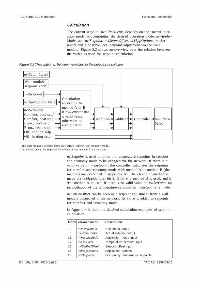
Calculation
The current setpoint, nvoEffectSetpt, depends on the current oper-ation mode, nvoUnitStatus, the desired operation mode, nviApplic-Mode, and nviSetpoint, nviSetpntOffset, nciAppOptions, nciSet-points and a possible local setpoint adjustment via the wallmodule. Figure 5.2 shows an overview over the relation betweenthe variables used for setpoint calculation.
nviSetpoint is used to allow the temperature setpoints in comfortand economy mode to be changed via the network. If there is avalid value on nviSetpoint, the controller calculates the setpointsfor comfort and economy mode with method A or method B (themethods are described in Appendix A). The choice of method ismade via nciAppOptions, bit 9. If bit 9=0 method B is used, and if9=1 method A is used. If there is no valid value on nviSetPoint, norecalculation of the temperature setpoints in nciSetpoints is made.
nviSetPntOffset can be seen as a setpoint adjustment from a wallmodule connected to the network. Its value is added to setpointsfor comfort and economy mode.
In Appendix A there are detailed calculation examples of setpointcalculation.
nciSetpointsComfort, cool.setp.Comfort, heat.setp.Econ., cool.setp.Econ., heat. setp.Off, cooling setp.Off, heating setp.
1 The wall module’s setpoint knob only affects comfort and economy mode. 2 In comfort mode, the setpoints for method A and method B are the same.
Figure 5.2 The relationen between variables for the setpoint calculation.
1
2
2
nviSetpntOffset
Wall modulesetpoint knob
nviSetpoint
nciAppOptions bit 9Calculationaccording tomethod A or Bif nviSetpoint hasa valid value,otherwise norecalculation
Addition Addition Controller nvoEffect-Setpt
Index Variable name Description
2 nvoUnitStatus Unit status output 5 nvoEffectSetpt Actual setpoint output15 nviApplicMode Application mode input
17 nviSetPoint Temperature setpoint input18 nviSetPntOffset Setpoint offset input24 nciAppOptions Application options25 nciSetpoints Occupancy temperature setpoints
TAC AB, 1999-08-16 0-004-7513-1 (GB), 5:7 (16)
TAC Xenta 101 Handbook Functional description
5.2.5 Control sequence with one valve output (controllers 1VF
and 1VFC)
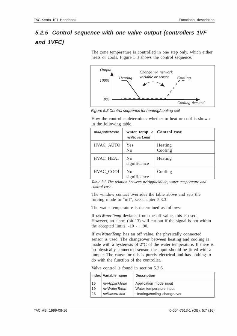
The zone temperature is controlled in one step only, which eitherheats or cools. Figure 5.3 shows the control sequence:
How the controller determines whether to heat or cool is shownin the following table.
nviApplicMode water temp. > Control casenciXoverLimit
HVAC_AUTO Yes HeatingNo Cooling
HVAC_HEAT No Heatingsignificance
HVAC_COOL No Coolingsignificance
Table 5.3 The relation between nviApplicMode, water temperature andcontrol case
The window contact overrides the table above and sets theforcing mode to “off”, see chapter 5.3.3.
The water temperature is determined as follows:
If nviWaterTemp deviates from the off value, this is used.However, an alarm (bit 13) will cut out if the signal is not withinthe accepted limits, -10 - + 90.
If nviWaterTemp has an off value, the physically connectedsensor is used. The changeover between heating and cooling ismade with a hysteresis of 2°C of the water temperature. If there isno physically connected sensor, the input should be fitted with ajumper. The cause for this is purely electrical and has nothing todo with the function of the controller.
Valve control is found in section 5.2.6.
Heating
Output
Cooling
Cooling demand0%
100%
Change via networkvariable or sensor
Figure 5.3 Control sequence for heating/cooling coil
Index Variable name Description
15 nviApplicMode Application mode input19 nviWaterTemp Water temperature input
26 nciXoverLimit Heating/cooling changeover
5:8 (16), 0-004-7513-1 (GB) TAC AB, 1999-08-16
TAC Xenta 101 Handbook Functional description
5.2.6 Control sequence with two valve outputs (controllers 2VF
and 2VFC)
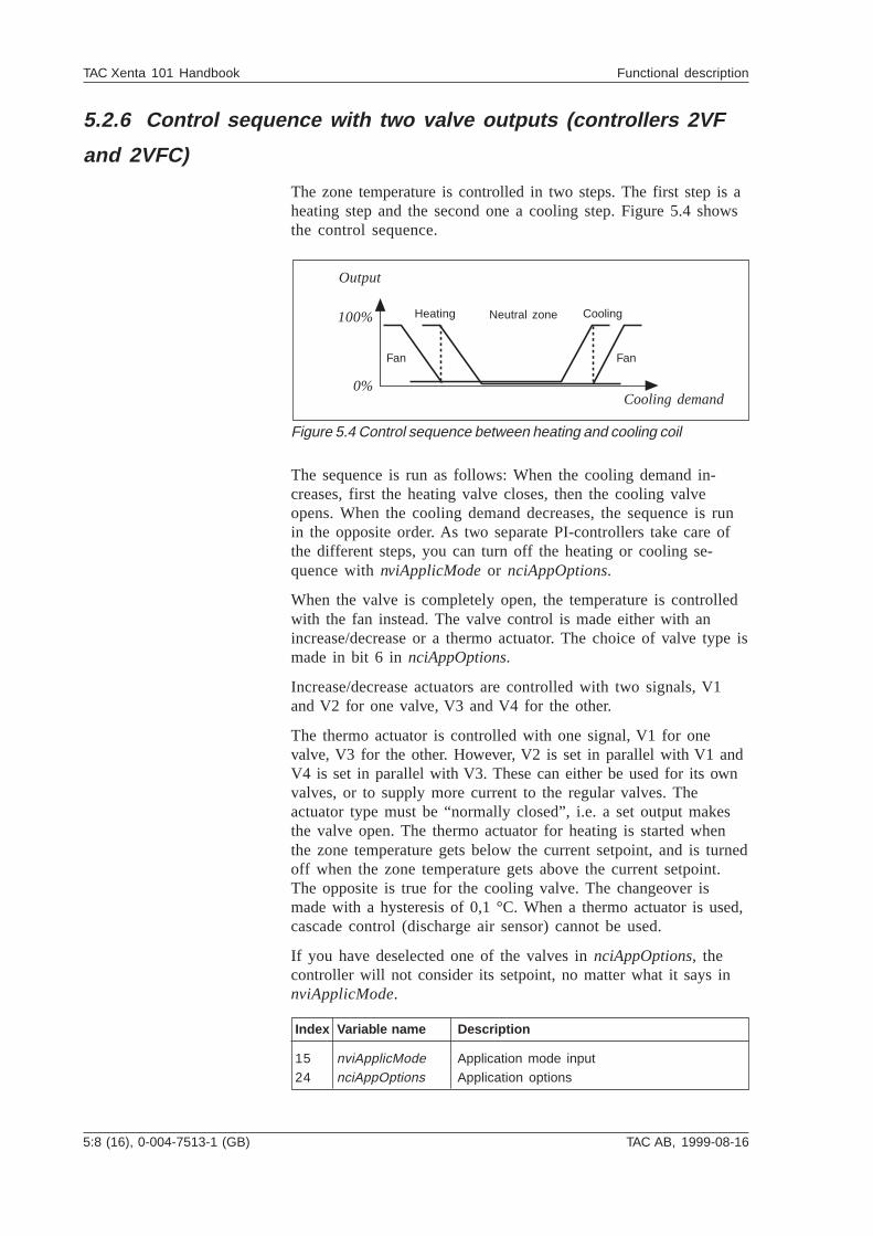
The zone temperature is controlled in two steps. The first step is aheating step and the second one a cooling step. Figure 5.4 showsthe control sequence.
The sequence is run as follows: When the cooling demand in-creases, first the heating valve closes, then the cooling valveopens. When the cooling demand decreases, the sequence is runin the opposite order. As two separate PI-controllers take care ofthe different steps, you can turn off the heating or cooling se-quence with nviApplicMode or nciAppOptions.
When the valve is completely open, the temperature is controlledwith the fan instead. The valve control is made either with anincrease/decrease or a thermo actuator. The choice of valve type ismade in bit 6 in nciAppOptions.
Increase/decrease actuators are controlled with two signals, V1and V2 for one valve, V3 and V4 for the other.
The thermo actuator is controlled with one signal, V1 for onevalve, V3 for the other. However, V2 is set in parallel with V1 andV4 is set in parallel with V3. These can either be used for its ownvalves, or to supply more current to the regular valves. Theactuator type must be “normally closed”, i.e. a set output makesthe valve open. The thermo actuator for heating is started whenthe zone temperature gets below the current setpoint, and is turnedoff when the zone temperature gets above the current setpoint.The opposite is true for the cooling valve. The changeover ismade with a hysteresis of 0,1 °C. When a thermo actuator is used,cascade control (discharge air sensor) cannot be used.
If you have deselected one of the valves in nciAppOptions, thecontroller will not consider its setpoint, no matter what it says innviApplicMode.
Index Variable name Description
15 nviApplicMode Application mode input24 nciAppOptions Application options
Heating
Output
Cooling
Cooling demand0%
100%
Figure 5.4 Control sequence between heating and cooling coil
Neutral zone
Fan Fan
TAC AB, 1999-08-16 0-004-7513-1 (GB), 5:9 (16)
TAC Xenta 101 Handbook Functional description
5.2.7 Fan control
On/off control
The controllers 1VF and 2VF use a relay output to control the fanon or off. In comfort and bypass mode, the fan runs constantly,and in economy and off mode, the fan is off, if there is no de-mand for heating or cooling. If necessary, the fan runs.
When the controller is forced into fan mode, the fan always run.When the controller is forced into off mode, the fan is off, apartfrom when the frost protection has cut out.
Speed control
The controllers 1VFC and 2VFC use output Y1 to control the fanspeed. nciMinFanSpeed (lowest fan speed) is used to set the fanspeed.
Increase/decrease actuator: In comfort and bypass mode, thefan runs at its lowest speed as long as the heating and/or coolingvalve can control the zone temperature. When either of the valvesis completely open, the controller controls the fan speed to be ableto control the temperature better.
Thermo actuator: In comfort and bypass mode, the fan runswhen the actuator output is enabled. The speed is controlled.
All actuators: In economy and off mode, the fan is off, if there isno demand for heating or cooling. If necessary, the fan runs at itslowest speed.
When the controller is forced into fan mode, the fan runs at itshighest speed. When the controller is forced into off mode, the fanis off, apart from when the frost protection has cut out.
See section 5.3.1 for further description of fan control.
Fan control and monitoring via a network
nvoFanSpeed (current fan speed) and fan_output in nvoUnitSta-tus (unit status) show current fan speed. nvoFanSpeed can alsoremote control a fan via the network.
Index Variable name Description
2 nvoUnitStatus Unit status output12 nvoFanSpeed Fan speed output37 nciMinFanSpeed Minimum fan speed
5:10 (16), 0-004-7513-1 (GB) TAC AB, 1999-08-16
TAC Xenta 101 Handbook Functional description
5.3 More about functions
5.3.1 Heating and cooling control
The zone temperature is controlled with a heating and coolingcontroller. In two-step control, the heating and cooling controllerswork in sequence. Both can be disabled, not depending on eachother, if you set the current network variables (see below).
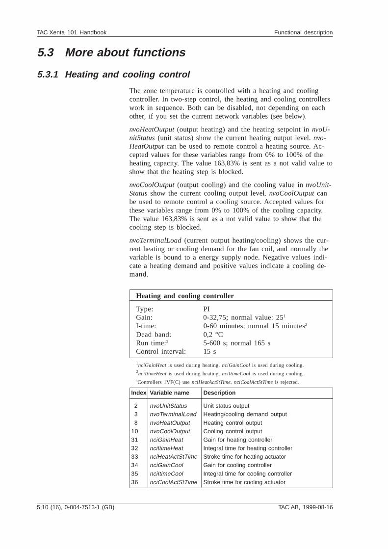
nvoHeatOutput (output heating) and the heating setpoint in nvoU-nitStatus (unit status) show the current heating output level. nvo-HeatOutput can be used to remote control a heating source. Ac-cepted values for these variables range from 0% to 100% of theheating capacity. The value 163,83% is sent as a not valid value toshow that the heating step is blocked.
nvoCoolOutput (output cooling) and the cooling value in nvoUnit-Status show the current cooling output level. nvoCoolOutput canbe used to remote control a cooling source. Accepted values forthese variables range from 0% to 100% of the cooling capacity.The value 163,83% is sent as a not valid value to show that thecooling step is blocked.
nvoTerminalLoad (current output heating/cooling) shows the cur-rent heating or cooling demand for the fan coil, and normally thevariable is bound to a energy supply node. Negative values indi-cate a heating demand and positive values indicate a cooling de-mand.
Heating and cooling controller
Type: PIGain: 0-32,75; normal value: 251
I-time: 0-60 minutes; normal 15 minutes2
Dead band: 0,2 °CRun time:3 5-600 s; normal 165 sControl interval: 15 s
1nciGainHeat is used during heating, nciGainCool is used during cooling.2nciItimeHeat is used during heating, nciItimeCool is used during cooling.3Controllers 1VF(C) use nciHeatActStTime. nciCoolActStTime is rejected.
Index Variable name Description
2 nvoUnitStatus Unit status output 3 nvoTerminalLoad Heating/cooling demand output
8 nvoHeatOutput Heating control output10 nvoCoolOutput Cooling control output31 nciGainHeat Gain for heating controller32 nciItimeHeat Integral time for heating controller33 nciHeatActStTime Stroke time for heating actuator34 nciGainCool Gain for cooling controller
35 nciItimeCool Integral time for cooling controller36 nciCoolActStTime Stroke time for cooling actuator
TAC AB, 1999-08-16 0-004-7513-1 (GB), 5:11 (16)
TAC Xenta 101 Handbook Functional description
The discharge air temperature setpoint can be limited to avoid thatthe controller lets too cool or too hot air into the zone (withnciDischAirMin and nciDischAirMax). The limits can be disabledby setting them to not valid values.
The controller sends the discharge air temperature in the variablenvoDischAirTemp. If the controller does not have a sensor, the notvalid value is sent. The variable is sent on the network when itsvalue has changed more than 0,5 °C since the last sendout.
Zone temperature controller
Type: PIGain: 0–32,75; normal value 251
I-time: 0–60 minutes; normal 15 minutes2
Dead band: 0,2 °CControl interval: 60 s
1nciGainHeat is used during heating, nciGainCool is used during cooling.2nciItimeHeat is used during heating, nciItimeCool is used during cooling.
Heating and cooling controller
Type: PIGain: 2I-time: 3 minutesDead band: 0,2 °CRun time: 5–600 s; normal 165 sControl interval: 15 s
5.3.2 Cascade control
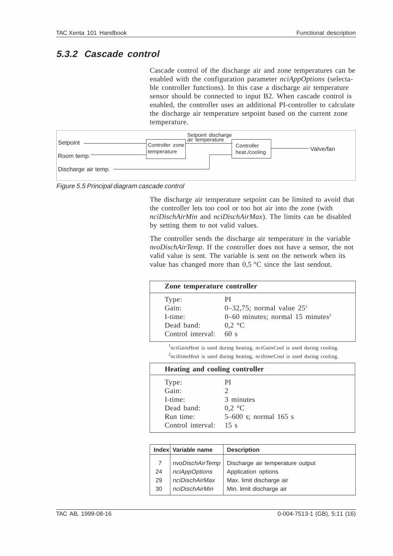
Cascade control of the discharge air and zone temperatures can beenabled with the configuration parameter nciAppOptions (selecta-ble controller functions). In this case a discharge air temperaturesensor should be connected to input B2. When cascade control isenabled, the controller uses an additional PI-controller to calculatethe discharge air temperature setpoint based on the current zonetemperature.
Setpoint
Room temp.
Discharge air temp.
Controller zonetemperature
Controllerheat./cooling Valve/fan
Setpoint dischargeair temperature
Figure 5.5 Principal diagram cascade control
Index Variable name Description
7 nvoDischAirTemp Discharge air temperature output 24 nciAppOptions Application options 29 nciDischAirMax Max. limit discharge air 30 nciDischAirMin Min. limit discharge air
5:12 (16), 0-004-7513-1 (GB) TAC AB, 1999-08-16
TAC Xenta 101 Handbook Functional description
5.3.3 Window contact
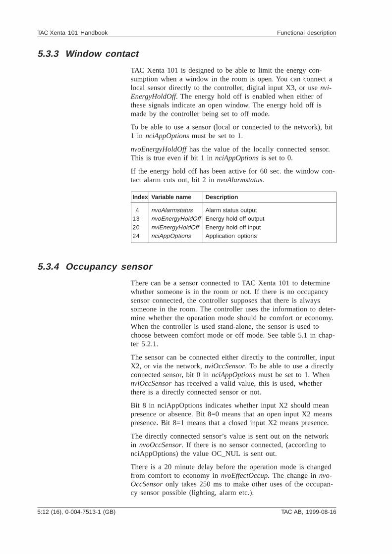
TAC Xenta 101 is designed to be able to limit the energy con-sumption when a window in the room is open. You can connect alocal sensor directly to the controller, digital input X3, or use nvi-EnergyHoldOff. The energy hold off is enabled when either ofthese signals indicate an open window. The energy hold off ismade by the controller being set to off mode.
To be able to use a sensor (local or connected to the network), bit1 in nciAppOptions must be set to 1.
nvoEnergyHoldOff has the value of the locally connected sensor.This is true even if bit 1 in nciAppOptions is set to 0.
If the energy hold off has been active for 60 sec. the window con-tact alarm cuts out, bit 2 in nvoAlarmstatus.
5.3.4 Occupancy sensor
There can be a sensor connected to TAC Xenta 101 to determinewhether someone is in the room or not. If there is no occupancysensor connected, the controller supposes that there is alwayssomeone in the room. The controller uses the information to deter-mine whether the operation mode should be comfort or economy.When the controller is used stand-alone, the sensor is used tochoose between comfort mode or off mode. See table 5.1 in chap-ter 5.2.1.
The sensor can be connected either directly to the controller, inputX2, or via the network, nviOccSensor. To be able to use a directlyconnected sensor, bit 0 in nciAppOptions must be set to 1. WhennviOccSensor has received a valid value, this is used, whetherthere is a directly connected sensor or not.
Bit 8 in nciAppOptions indicates whether input X2 should meanpresence or absence. Bit 8=0 means that an open input X2 meanspresence. Bit 8=1 means that a closed input X2 means presence.
The directly connected sensor’s value is sent out on the networkin nvoOccSensor. If there is no sensor connected, (according tonciAppOptions) the value OC_NUL is sent out.
There is a 20 minute delay before the operation mode is changedfrom comfort to economy in nvoEffectOccup. The change in nvo-OccSensor only takes 250 ms to make other uses of the occupan-cy sensor possible (lighting, alarm etc.).
Index Variable name Description
4 nvoAlarmstatus Alarm status output13 nvoEnergyHoldOff Energy hold off output
20 nviEnergyHoldOff Energy hold off input24 nciAppOptions Application options
TAC AB, 1999-08-16 0-004-7513-1 (GB), 5:13 (16)
TAC Xenta 101 Handbook Functional description
Index Variable name Description24 nciAppOptions Application options39 nvoOccSensor Occupancy sensor output40 nviOccSensor Occupancy sensor input
Index Variable name Description 2 nvoUnitStatus Unit status output 3 nvoTerminalLoad Heating/cooling demand output 8 nvoHeatOutput Heating control output33 nciHeatActStTime Stroke time for heating actuator41 nciHeatPrimMin Minimum output heating controller
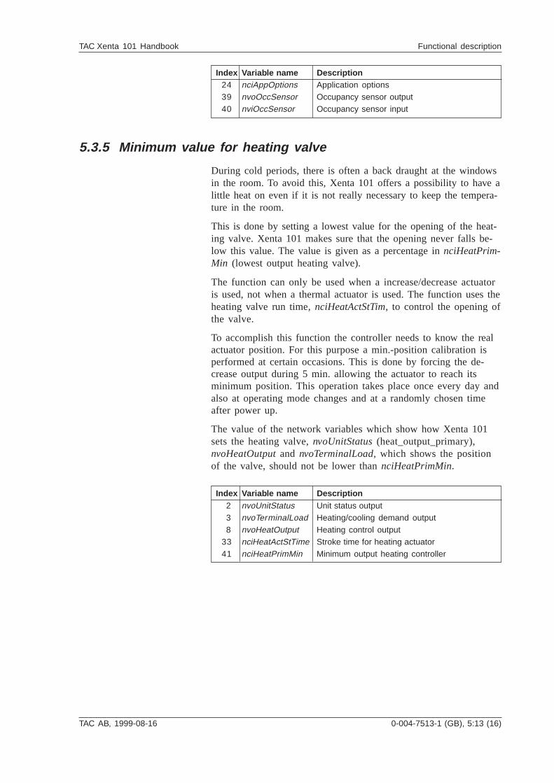
5.3.5 Minimum value for heating valve
During cold periods, there is often a back draught at the windowsin the room. To avoid this, Xenta 101 offers a possibility to have alittle heat on even if it is not really necessary to keep the tempera-ture in the room.
This is done by setting a lowest value for the opening of the heat-ing valve. Xenta 101 makes sure that the opening never falls be-low this value. The value is given as a percentage in nciHeatPrim-Min (lowest output heating valve).
The function can only be used when a increase/decrease actuatoris used, not when a thermal actuator is used. The function uses theheating valve run time, nciHeatActStTim, to control the opening ofthe valve.
To accomplish this function the controller needs to know the realactuator position. For this purpose a min.-position calibration isperformed at certain occasions. This is done by forcing the de-crease output during 5 min. allowing the actuator to reach itsminimum position. This operation takes place once every day andalso at operating mode changes and at a randomly chosen timeafter power up.
The value of the network variables which show how Xenta 101sets the heating valve, nvoUnitStatus (heat_output_primary),nvoHeatOutput and nvoTerminalLoad, which shows the positionof the valve, should not be lower than nciHeatPrimMin.
5:14 (16), 0-004-7513-1 (GB) TAC AB, 1999-08-16
TAC Xenta 101 Handbook Functional description
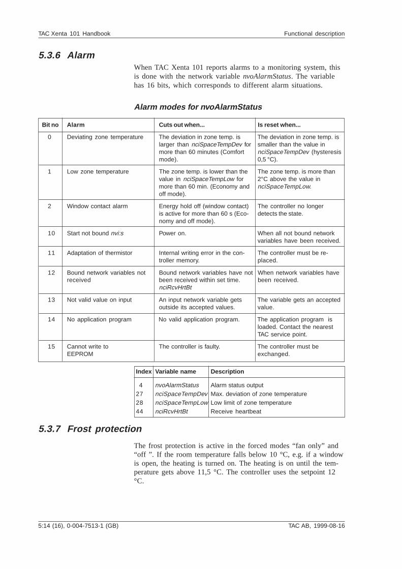
5.3.6 AlarmWhen TAC Xenta 101 reports alarms to a monitoring system, thisis done with the network variable nvoAlarmStatus. The variablehas 16 bits, which corresponds to different alarm situations.
Alarm modes for nvoAlarmStatus
Bit no Alarm Cuts out when... Is reset when...
0 Deviating zone temperature The deviation in zone temp. is The deviation in zone temp. islarger than nciSpaceTempDev for smaller than the value inmore than 60 minutes (Comfort nciSpaceTempDev (hysteresismode). 0,5 °C).
1 Low zone temperature The zone temp. is lower than the The zone temp. is more thanvalue in nciSpaceTempLow for 2°C above the value inmore than 60 min. (Economy and nciSpaceTempLow.off mode).
2 Window contact alarm Energy hold off (window contact) The controller no longeris active for more than 60 s (Eco- detects the state.nomy and off mode).
10 Start not bound nvi:s Power on. When all not bound networkvariables have been received.
11 Adaptation of thermistor Internal writing error in the con- The controller must be re-troller memory. placed.
12 Bound network variables not Bound network variables have not When network variables havereceived been received within set time. been received.
nciRcvHrtBt
13 Not valid value on input An input network variable gets The variable gets an acceptedoutside its accepted values. value.
14 No application program No valid application program. The application program isloaded. Contact the nearestTAC service point.
15 Cannot write to The controller is faulty. The controller must beEEPROM exchanged.
5.3.7 Frost protection
The frost protection is active in the forced modes “fan only” and“off ”. If the room temperature falls below 10 °C, e.g. if a windowis open, the heating is turned on. The heating is on until the tem-perature gets above 11,5 °C. The controller uses the setpoint 12°C.
Index Variable name Description
4 nvoAlarmStatus Alarm status output27 nciSpaceTempDev Max. deviation of zone temperature28 nciSpaceTempLow Low limit of zone temperature44 nciRcvHrtBt Receive heartbeat
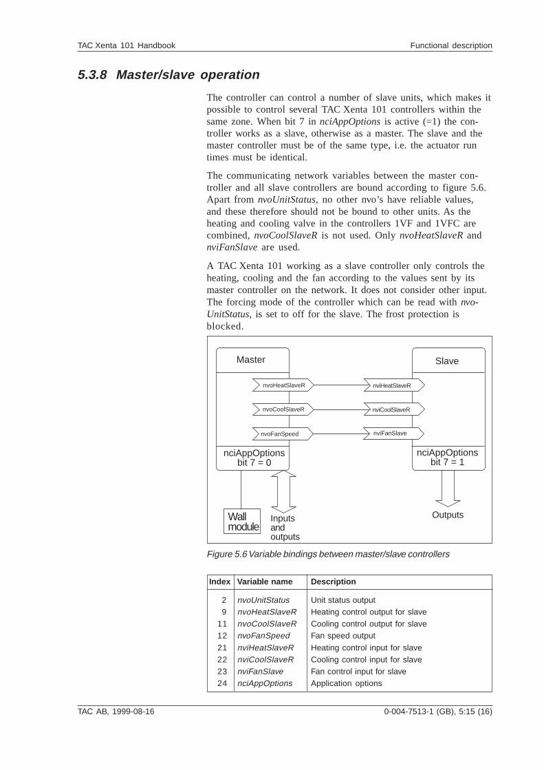
TAC AB, 1999-08-16 0-004-7513-1 (GB), 5:15 (16)
TAC Xenta 101 Handbook Functional description
5.3.8 Master/slave operation
The controller can control a number of slave units, which makes itpossible to control several TAC Xenta 101 controllers within thesame zone. When bit 7 in nciAppOptions is active (=1) the con-troller works as a slave, otherwise as a master. The slave and themaster controller must be of the same type, i.e. the actuator runtimes must be identical.
The communicating network variables between the master con-troller and all slave controllers are bound according to figure 5.6.Apart from nvoUnitStatus, no other nvo’s have reliable values,and these therefore should not be bound to other units. As theheating and cooling valve in the controllers 1VF and 1VFC arecombined, nvoCoolSlaveR is not used. Only nvoHeatSlaveR andnviFanSlave are used.
A TAC Xenta 101 working as a slave controller only controls theheating, cooling and the fan according to the values sent by itsmaster controller on the network. It does not consider other input.The forcing mode of the controller which can be read with nvo-UnitStatus, is set to off for the slave. The frost protection isblocked.
Master
nvoFanSpeed
nciAppOptionsbit 7 = 0
nvoCoolSlaveR
nvoHeatSlaveR nviHeatSlaveR
nviCoolSlaveR
nviFanSlave
nciAppOptionsbit 7 = 1
Slave
Inputsandoutputs
Wallmodule
Outputs
Figure 5.6 Variable bindings between master/slave controllers
Index Variable name Description
2 nvoUnitStatus Unit status output 9 nvoHeatSlaveR Heating control output for slave11 nvoCoolSlaveR Cooling control output for slave12 nvoFanSpeed Fan speed output
21 nviHeatSlaveR Heating control input for slave22 nviCoolSlaveR Cooling control input for slave23 nviFanSlave Fan control input for slave24 nciAppOptions Application options
5:16 (16), 0-004-7513-1 (GB) TAC AB, 1999-08-16
TAC Xenta 101 Handbook Functional description
Blank page
TAC AB, 1999-08-16 0-004-7513-1 (GB), 6:1 (4)
TAC Xenta 101 Handbook Trouble-shooting
6 Trouble-shooting
6.1 GeneralTAC Xenta 101 is normally a very reliable controller. If there areany problems, you can use the trouble-shooting tips in this chap-ter, preferably when the controller is run on a network, but alsowhen it is used stand-alone. If you need further help, please con-tact the nearest TAC service point.
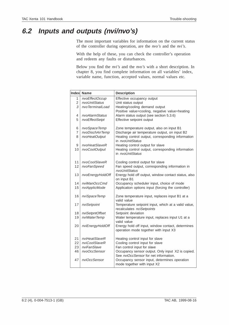
6:2 (4), 0-004-7513-1 (GB) TAC AB, 1999-08-16
TAC Xenta 101 Handbook Trouble-shooting
Index Name Description
1 nvoEffectOccup Effective occupancy output2 nvoUnitStatus Unit status output3 nvoTerminalLoad Heating/cooling demand output
Positive value=cooling, negative value=heating4 nvoAlarmStatus Alarm status output (see section 5.3.6)5 nvoEffectSetpt Effective setpoint output
6 nvoSpaceTemp Zone temperature output, also on input B17 nvoDischAirTemp Discharge air temperature output, on input B28 nvoHeatOutput Heating control output, corresponding information
in nvoUnitStatus9 nvoHeatSlaveR Heating control output for slave
10 nvoCoolOutput Heating control output, corresponding informationin nvoUnitStatus
11 nvoCoolSlaveR Cooling control output for slave12 nvoFanSpeed Fan speed output, corresponding information in
nvoUnitStatus13 nvoEnergyHoldOff Energy hold off output, window contact status, also
on input B114 nviManOccCmd Occupancy scheduler input, choice of mode15 nviApplicMode Application options input (forcing the controller)
16 nviSpaceTemp Zone temperature input, replaces input B1 at avalid value
17 nviSetpoint Temperature setpoint input, which at a valid value,recalculates nciSetpoints
18 nviSetpntOffset Setpoint deviation19 nviWaterTemp Water temperature input, replaces input U1 at a
valid value20 nviEnergyHoldOff Energy hold off input, window contact, determines
operation mode together with input X3
21 nviHeatSlaveR Heating control input for slave22 nviCoolSlaveR Cooling control input for slave23 nviFanSlave Fan control input for slave46 nvoOccSensor Occupancy sensor output. Only input X2 is copied.
See nviOccSensor for net information.47 nviOccSensor Occupancy sensor input, determines operation
mode together with input X2
6.2 Inputs and outputs (nvi/nvo’s)The most important variables for information on the current statusof the controller during operation, are the nvo’s and the nvi’s.
With the help of these, you can check the controller’s operationand redeem any faults or disturbances.
Below you find the nvi’s and the nvo’s with a short description. Inchapter 8, you find complete information on all variables’ index,variable name, function, accepted values, normal values etc.
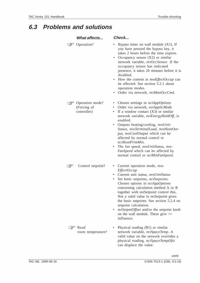
TAC AB, 1999-08-16 0-004-7513-1 (GB), 6:3 (4)
TAC Xenta 101 Handbook Trouble-shooting
Operation?
Operation mode?(Forcing ofcontroller)
Check...
• Bypass timer on wall module (X1). Ifyou have pressed the bypass key, ittakes 2 hours before the time expires.
• Occupancy sensor (X2) or similarnetwork variable, nviOccSensor. If theoccupancy sensor has indicatedpresence, it takes 20 minutes before it isdisabled.
• How the content in nvoEffectOccup canbe affected. See section 5.2.1 aboutoperation modes.
• Order via network, nviManOccCmd.
• Chosen settings in nciAppOptions• Order via network, nviApplicMode• If a window contact (X3) or similar
network variable, nviEnergyHoldOff, isenabled.
• Outputs heating/cooling, nvoUnit-Status, nvoTerminalLoad, nvoHeatOut-put, nvoCoolOutput which can beaffected by normal control ornciHeatPrimMin.
• The fan speed, nvoUnitStatus, nvo-FanSpeed which can be affected bynormal control or nciMinFanSpeed.
6.3 Problems and solutions
What affects...
cont.
Control setpoint? • Current operation mode, nvo-EffectOccup
• Current unit status, nvoUnitStatus• Set basic setpoints, nciSetpoints.
Chosen options in nciAppOptionsconcerning calculation method A or Btogether with nviSetpoint control this.Not a valid value in nviSetpoint givesthe basic setpoints. See section 5.2.4 onsetpoint calculation.
• nviSetpntOffset and/or the setpoint knobon the wall module. These give +/-influence.
Readroom temperature?
• Physical reading (B1) or similarnetwork variable, nviSpaceTemp. Avalid value on the network overrides aphysical reading. nciSpaceTempOfstcan displace the value.
6:4 (4), 0-004-7513-1 (GB) TAC AB, 1999-08-16
TAC Xenta 101 Handbook Trouble-shooting
What affects... Check...
The LED on the wallmodule?
• That the controller receives power alsowhen the LED is out.
• The controller when the service LED islit. This indicates that the controllerdoes not work correctly and should bereplaced.
• The controller when the service LED islit for 15 seconds and the goes out. Thisis not a fault, but an indication that thecontroller answers a “wink” commandfrom the network.
• Current operation.
• Only physical input (B2). This is usedfor cascade control according to choicewith nciAppOptions. The control ismax. and min. limited vianciDischAirMax and nciDischAirMin.See section 5.3.2 on cascade control.
Read discharge airtemperature?
• Current operation mode, nvoEffect-Occup
• Current values in nciSpaceTempDevand nciSpaceTempLow.
• If a window is open (window contact).See also section 5.3.6 on alarms.
That an alarm is set?
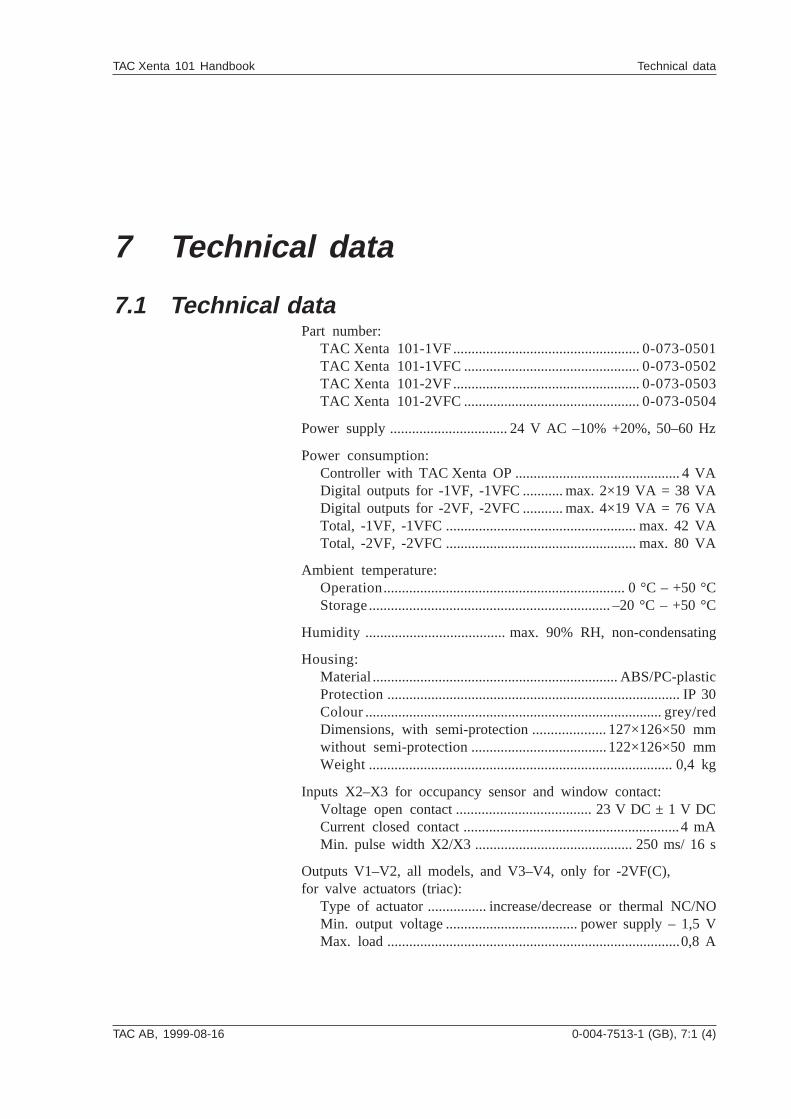
TAC AB, 1999-08-16 0-004-7513-1 (GB), 7:1 (4)
TAC Xenta 101 Handbook Technical data
7 Technical data
7.1 Technical dataPart number:
TAC Xenta 101-1VF...................................................0-073-0501TAC Xenta 101-1VFC................................................0-073-0502TAC Xenta 101-2VF...................................................0-073-0503TAC Xenta 101-2VFC................................................0-073-0504
Power supply ................................ 24 V AC –10% +20%, 50–60 Hz
Power consumption:Controller with TAC Xenta OP ............................................. 4 VADigital outputs for -1VF, -1VFC ........... max. 2×19 VA = 38 VADigital outputs for -2VF, -2VFC ........... max. 4×19 VA = 76 VATotal, -1VF, -1VFC .................................................... max. 42 VATotal, -2VF, -2VFC .................................................... max. 80 VA
Ambient temperature:Operation.................................................................. 0 °C – +50 °CStorage.................................................................. –20 °C – +50 °C
Humidity ...................................... max. 90% RH, non-condensating
Housing:Material...................................................................ABS/PC-plasticProtection................................................................................ IP 30Colour.................................................................................grey/redDimensions, with semi-protection ....................127×126×50 mmwithout semi-protection.....................................122×126×50 mmWeight................................................................................... 0,4 kg
Inputs X2–X3 for occupancy sensor and window contact:Voltage open contact ..................................... 23 V DC ± 1 V DCCurrent closed contact ...........................................................4 mAMin. pulse width X2/X3 ........................................... 250 ms/ 16 s
Outputs V1–V2, all models, and V3–V4, only for -2VF(C),for valve actuators (triac):
Type of actuator ................ increase/decrease or thermal NC/NOMin. output voltage .................................... power supply – 1,5 VMax. load ................................................................................0,8 A
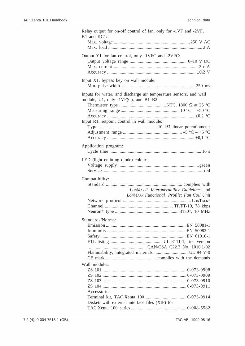
7:2 (4), 0-004-7513-1 (GB) TAC AB, 1999-08-16
TAC Xenta 101 Handbook Technical data
Relay output for on-off control of fan, only for -1VF and -2VF,K1 and KC1:
Max. voltage ...................................................................250 V ACMax. load ................................................................................... 2 A
Output Y1 for fan control, only -1VFC and -2VFC:Output voltage range .................................................. 0–10 V DCMax. current ............................................................................2 mAAccuracy.............................................................................. ±0,2 V
Input X1, bypass key on wall module:Min. pulse width ..................................................................250 ms
Inputs for water, and discharge air temperature sensors, and wallmodule, U1, only -1VF(C), and B1–B2:
Thermistor type .........................................NTC, 1800 Ω at 25 °CMeasuring range.................................................. –10 °C – +50 °CAccuracy............................................................................. ±0,2 °C
Input R1, setpoint control in wall module:Type.................................................... 10 kΩ linear potentiometerAdjustment range.................................................... –5 °C – +5 °CAccuracy............................................................................. ±0,1 °C
Application program:Cycle time ................................................................................. 16 s
LED (light emitting diode) colour:Voltage supply........................................................................greenService......................................................................................... red
Compatibility:Standard................................................................... complies with
LONMARK® Interoperability Guidelines andLONMARK Functional Profile: Fan Coil Unit
Network protocol............................................................ LONTALK ®
Channel............................................................ TP/FT-10, 78 kbpsNeuron® type........................................................ 3150®, 10 MHz
Standards/Norms:Emission...................................................................... EN 50081-1Immunity..................................................................... EN 50082-1Safety........................................................................... EN 61010-1ETL listing ............................................... UL 3111-1, first version................................................... CAN/CSA C22.2 No. 1010.1-92
Flammability, integrated materials ...............................UL 94 V-0CE mark ............................................. complies with the demands
Wall modules:ZS 101 ..........................................................................0-073-0908ZS 102 ..........................................................................0-073-0909ZS 103 ..........................................................................0-073-0910ZS 104 ..........................................................................0-073-0911Accessories:Terminal kit, TAC Xenta 100.....................................0-073-0914Diskett with external interface files (XIF) forTAC Xenta 100 series .................................................0-008-5582
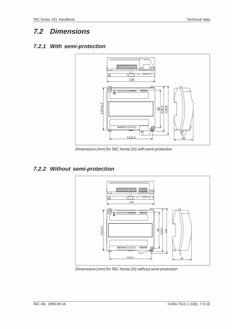
TAC AB, 1999-08-16 0-004-7513-1 (GB), 7:3 (4)
TAC Xenta 101 Handbook Technical data
126
110±
0,2
112±1
9811
8,2
126,
8
50
Dimensions (mm) for TAC Xenta 101 with semi-protection
7.2 Dimensions
7.2.1 With semi-protection
7.2.2 Without semi-protection
126
110±
0,2
112±1
9811
8,2
122
50
Dimensions (mm) for TAC Xenta 101 without semi-protection
7:4 (4), 0-004-7513-1 (GB) TAC AB, 1999-08-16
TAC Xenta 101 Handbook Technical data
Blank page
TAC AB, 1999-08-16 0-004-7513-1 (GB), 8:1 (8)
TAC Xenta 101 Handbook Communication
8 Communication
8.1 GeneralThe controller consists of two LonMark™ objects: the node object(section 8.5) and the controller object (section 8.6). These objectsare monitored by means of the network variables nviRequest (ob-ject request) and nvoStatus (object status).
The network variable nciLocation (position mark) is used whenconfiguring the basic parameters (section 4.1) to give a detaileddescription of the actual place where the controller is fitted. Thevariable receives an arbitrary string of signs and dividers as longas the string is no longer than 30 signs. You can program a certainlocation label, e.g.
TAMF.main.floor3.room343/RC40
A LNS based network management tool uses nciLocation when adata base should be recreated. The monitoring of an already in-stalled network is made by the LNS tool reading nciLocation, andthen using the information to give the node a subsystem name anda unit name. The string should therefore consist of a name and asearch path for the subsystem, followed by a slash and the unitname, i.e.
system.subsystem[.subsystem...]/unit name
8.2 Default settings and power onFor all network variables the following settings are valid:
• Number of sent messages per time unit: NONE• Service type: NOT CONFIRMED if not stated otherwise• Access check: NO, possible to configure: YES.• Polled: NO for all nvo and nci, YES for all nvi (startingup)• Synchronized: NO• Change/update only when the controller is not active on the
network; flags = NO• Restart of TAC Xenta 101 after change; flags = YES
All network variables have the same index as they have in themenu tree in the operator panel TAC Xenta OP. They represent theorder, in which they have been declared in the system program, asthe order is important for variables’ self documentatory string. The
8:2 (8), 0-004-7513-1 (GB) TAC AB, 1999-08-16
TAC Xenta 101 Handbook Communication
variables are of standard type or so called SNVT, and the valueseach SNVT can receive, are listed in the tables in this chapter.Apart from SNVT, there are also standard configuration parame-ters (SCPT) and parameter types for user configuration (UCPT). Ifyou want general information about which SNVT/SCPT/UCPTthere are and which values they can receive, the “The SNVT Mas-ter List and Programmer's Guide” on the internet addresswww.lonmark.org are a good source of information.
At power on, all variables for inputs and outputs (nvi and nvo) re-ceives their default values after a restart, as the configuration para-meters (nci) keep their earlier set values. After a restart all nvi’swill send a request to the nvo’s they are bound to (a poll).
8.3 Monitoring network variables, HeartbeatIn Xenta 101 there is a function, called Heartbeat, which can beconfigured to monitor input and output variables on the network.
In the overviews in this chapter, you can see whether the variableis monitored with Heartbeat in the column Hb.
Inputs
Some of the inputs in Xenta 101 are monitored in a way that thevariable must receive values within a certain time for it to beregarded as valid. If no value is received within this time, thevariable will return to its default value. Also, an alarm is enabled,bit 12 in nvoAlarmStatus.
Which outputs are monitored in this way, you find in the list ofnetwork variables in chapter 8.6.1.
The time is set with the variable nciRcvHrtBt. Its default value is0.0, which means that no monitoring is performed.
Outputs
The bound outputs are normally sent out when they are changed.Most outputs in Xenta 101 are monitored, so even if the valuesare not changed, they are sent out at even intervals.
Which outputs are monitored in this way, you find in the list ofnetwork variables in chapter 8.6.2.
The time is set with the variable nciSndHrtBt. Its normal value is0.0, which means that no monitoring is performed.
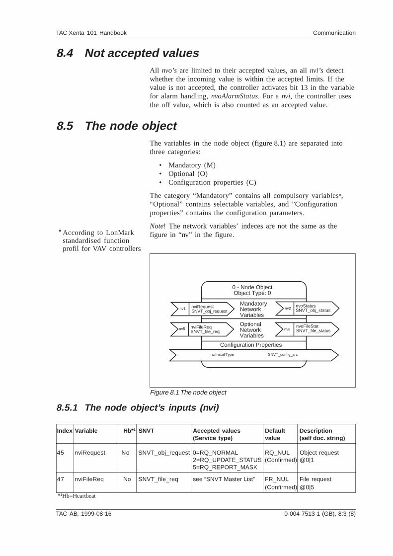
TAC AB, 1999-08-16 0-004-7513-1 (GB), 8:3 (8)
TAC Xenta 101 Handbook Communication
8.4 Not accepted valuesAll nvo’s are limited to their accepted values, an all nvi’s detectwhether the incoming value is within the accepted limits. If thevalue is not accepted, the controller activates bit 13 in the variablefor alarm handling, nvoAlarmStatus. For a nvi, the controller usesthe off value, which is also counted as an accepted value.
8.5 The node objectThe variables in the node object (figure 8.1) are separated intothree categories:
• Mandatory (M)• Optional (O)• Configuration properties (C)
The category “Mandatory” contains all compulsory variables*,“Optional” contains selectable variables, and ”Configurationproperties” contains the configuration parameters.
Note! The network variables’ indeces are not the same as thefigure in “nv” in the figure.
8.5.1 The node object’s inputs (nvi)
Index Variable Hb* 1 SNVT Accepted values Default Description(Service type) value (self doc. string)
45 nviRequest No SNVT_obj_request 0=RQ_NORMAL RQ_NUL Object request2=RQ_UPDATE_STATUS (Confirmed) @0|15=RQ_REPORT_MASK
47 nviFileReq No SNVT_file_req see “SNVT Master List” FR_NUL File request(Confirmed) @0|5
Figure 8.1 The node object
*1Hb=Heartbeat
According to LonMarkstandardised functionprofil for VAV controllers
*
nv1 nv2
nv6
nviRequestSNVT_obj_request
nvoStatusSNVT_obj_status
nvoFileStatSNVT_file_status
nciInstallType SNVT_config_src
Configuration Properties
MandatoryNetworkVariables
OptionalNetworkVariables
0 - Node ObjectObject Type: 0
nv5 nviFileReqSNVT_file_req
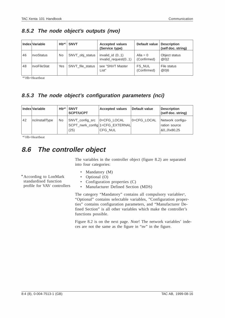
8:4 (8), 0-004-7513-1 (GB) TAC AB, 1999-08-16
TAC Xenta 101 Handbook Communication
8.5.2 The node object’s outputs (nvo)
Index Variable Hb* 1 SNVT Accepted values Default value Description(Service type) (self doc. string)
46 nvoStatus No SNVT_obj_status invalid_id (0..1) Alla = 0 Object statusinvalid_request(0..1) (Confirmed) @0|2
48 nvoFileStat Yes SNVT_file_status see ”SNVT Master FS_NUL File statusList” (Confirmed) @0|6
8.5.3 The node object’s configuration parameters (nci)
Index Variable Hb* 1 SNVT Accepted values Default value DescriptionSCPT/UCPT (self doc. string)
42 nciInstallType No SNVT_config_src 0=CFG_LOCAL 0=CFG_LOCAL Network configu-
SCPT_nwrk_config 1=CFG_EXTERNAL ration source(25) CFG_NUL &0,,0\x80,25
8.6 The controller objectThe variables in the controller object (figure 8.2) are separatedinto four categories:
• Mandatory (M)• Optional (O)• Configuration properties (C)• Manufacturer Defined Section (MDS)
The category “Mandatory” contains all compulsory variables*,“Optional” contains selectable variables, ”Configuration proper-ties” contains configuration parameters, and “Manufacturer De-fined Section” is all other variables which make the controller’sfunctions possible.
Figure 8.2 is on the next page. Note! The network variables’ inde-ces are not the same as the figure in “nv” in the figure.
*1 Hb=Heartbeat
*1 Hb=Heartbeat
According to LonMarkstandardised functionprofile for VAV controllers
*
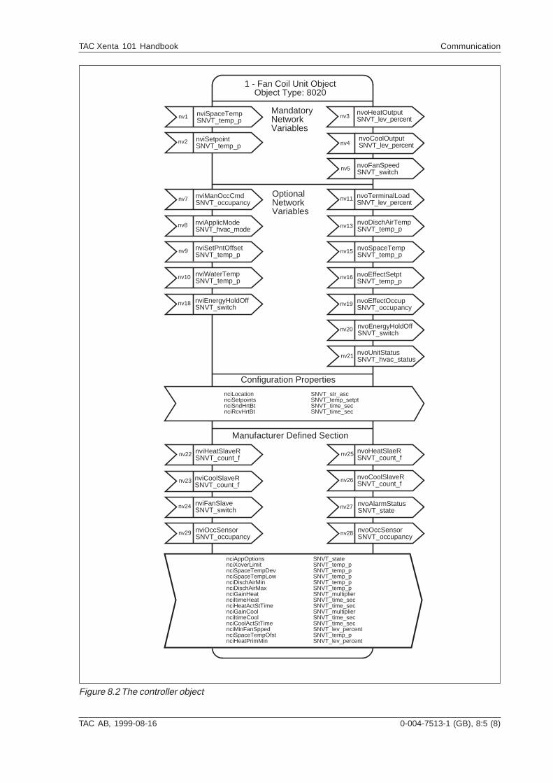
TAC AB, 1999-08-16 0-004-7513-1 (GB), 8:5 (8)
TAC Xenta 101 Handbook Communication
Figure 8.2 The controller object
nv1
nv2
nv3
nv4
nv5
nv7
nv8
nv9
nv10
nv18
nv11
nv13
nv16
nv15
nv19
nv20
nv21
nv25
nv26
nv27
nv28
nv22
nv23
nv24
nv29
nviSpaceTempSNVT_temp_p
nviSetpointSNVT_temp_p
nviManOccCmdSNVT_occupancy
nviApplicModeSNVT_hvac_mode
nviSetPntOffsetSNVT_temp_p
nviWaterTempSNVT_temp_p
nviEnergyHoldOffSNVT_switch
nviHeatSlaveRSNVT_count_f
nviCoolSlaveRSNVT_count_f
nviFanSlaveSNVT_switch
nviOccSensorSNVT_occupancy
nvoHeatOutputSNVT_lev_percent
nvoCoolOutputSNVT_lev_percent
nvoFanSpeedSNVT_switch
nvoTerminalLoadSNVT_lev_percent
nvoDischAirTempSNVT_temp_p
nvoSpaceTempSNVT_temp_p
nvoEffectSetptSNVT_temp_p
nvoEffectOccupSNVT_occupancy
nvoEnergyHoldOffSNVT_switch
nvoUnitStatusSNVT_hvac_status
nvoHeatSlaeRSNVT_count_f
nvoCoolSlaveRSNVT_count_f
nvoAlarmStatusSNVT_state
nvoOccSensorSNVT_occupancy
nciLocation SNVT_str_ascnciSetpoints SNVT_temp_setptnciSndHrtBt SNVT_time_secnciRcvHrtBt SNVT_time_sec
Configuration Properties
Manufacturer Defined Section
nciAppOptions SNVT_statenciXoverLimit SNVT_temp_pnciSpaceTempDev SNVT_temp_pnciSpaceTempLow SNVT_temp_pnciDischAirMin SNVT_temp_pnciDischAirMax SNVT_temp_pnciGainHeat SNVT_multipliernciItimeHeat SNVT_time_secnciHeatActStTime SNVT_time_secnciGainCool SNVT_multipliernciItimeCool SNVT_time_secnciCoolActStTime SNVT_time_secnciMinFanSpped SNVT_lev_percentnciSpaceTempOfst SNVT_temp_pnciHeatPrimMin SNVT_lev_percent
MandatoryNetworkVariables
OptionalNetworkVariables
1 - Fan Coil Unit ObjectObject Type: 8020
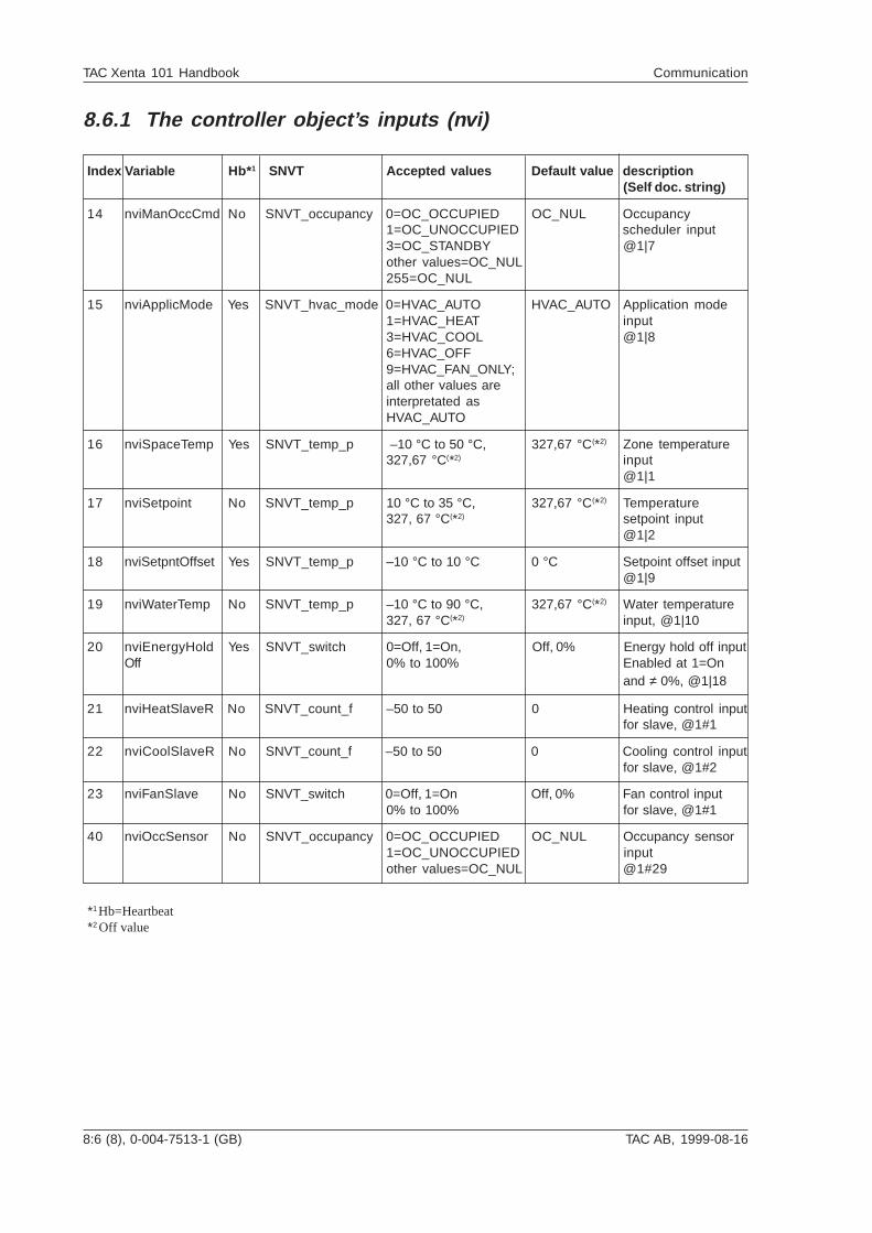
8:6 (8), 0-004-7513-1 (GB) TAC AB, 1999-08-16
TAC Xenta 101 Handbook Communication
8.6.1 The controller object’s inputs (nvi)
Index Variable Hb* 1 SNVT Accepted values Default value description(Self doc. string)
14 nviManOccCmd No SNVT_occupancy 0=OC_OCCUPIED OC_NUL Occupancy1=OC_UNOCCUPIED scheduler input3=OC_STANDBY @1|7other values=OC_NUL255=OC_NUL
15 nviApplicMode Yes SNVT_hvac_mode 0=HVAC_AUTO HVAC_AUTO Application mode1=HVAC_HEAT input3=HVAC_COOL @1|86=HVAC_OFF9=HVAC_FAN_ONLY;all other values areinterpretated asHVAC_AUTO
16 nviSpaceTemp Yes SNVT_temp_p –10 °C to 50 °C, 327,67 °C(*2) Zone temperature327,67 °C(*2) input
@1|1
17 nviSetpoint No SNVT_temp_p 10 °C to 35 °C, 327,67 °C(*2) Temperature327, 67 °C(*2) setpoint input
@1|2
18 nviSetpntOffset Yes SNVT_temp_p –10 °C to 10 °C 0 °C Setpoint offset input@1|9
19 nviWaterTemp No SNVT_temp_p –10 °C to 90 °C, 327,67 °C(*2) Water temperature327, 67 °C(*2) input, @1|10
20 nviEnergyHold Yes SNVT_switch 0=Off, 1=On, Off, 0% Energy hold off inputOff 0% to 100% Enabled at 1=On
and ≠ 0%, @1|18
21 nviHeatSlaveR No SNVT_count_f –50 to 50 0 Heating control inputfor slave, @1#1
22 nviCoolSlaveR No SNVT_count_f –50 to 50 0 Cooling control inputfor slave, @1#2
23 nviFanSlave No SNVT_switch 0=Off, 1=On Off, 0% Fan control input0% to 100% for slave, @1#1
40 nviOccSensor No SNVT_occupancy 0=OC_OCCUPIED OC_NUL Occupancy sensor1=OC_UNOCCUPIED inputother values=OC_NUL @1#29
*1 Hb=Heartbeat*2 Off value
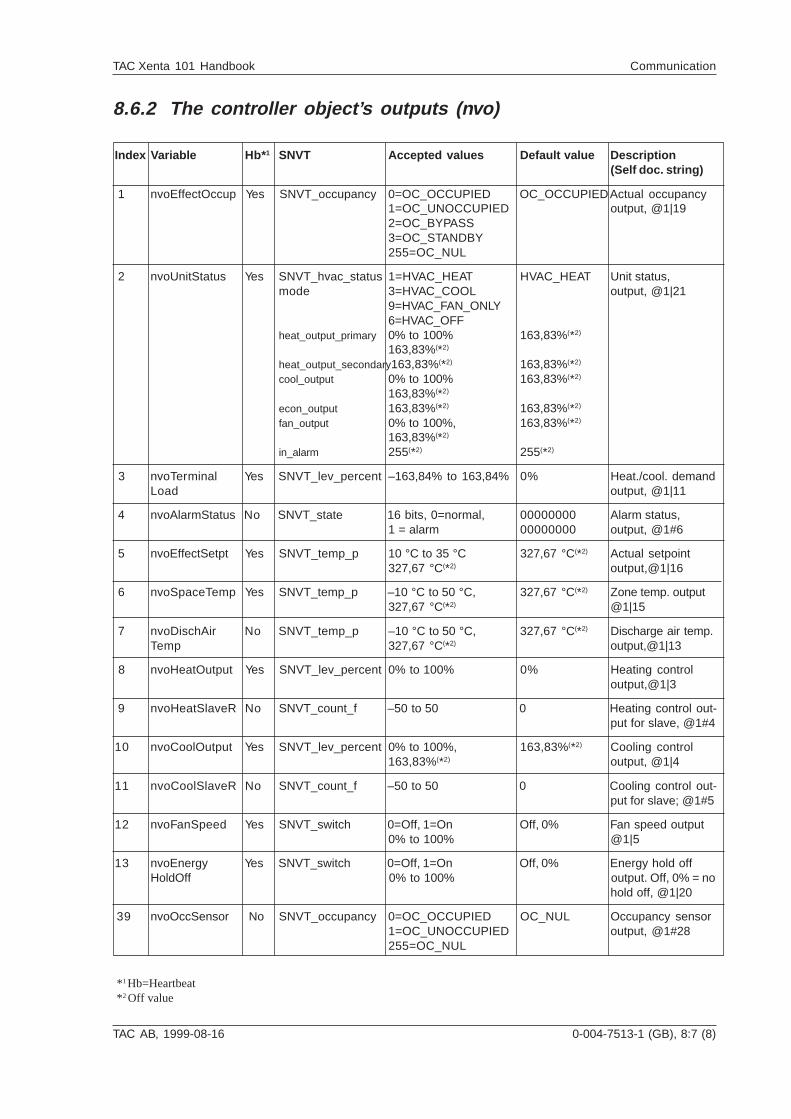
TAC AB, 1999-08-16 0-004-7513-1 (GB), 8:7 (8)
TAC Xenta 101 Handbook Communication
8.6.2 The controller object’s outputs (nvo)
Index Variable Hb* 1 SNVT Accepted values Default value Description(Self doc. string)
1 nvoEffectOccup Yes SNVT_occupancy 0=OC_OCCUPIED OC_OCCUPIEDActual occupancy1=OC_UNOCCUPIED output, @1|192=OC_BYPASS3=OC_STANDBY255=OC_NUL
2 nvoUnitStatus Yes SNVT_hvac_status 1=HVAC_HEAT HVAC_HEAT Unit status,mode 3=HVAC_COOL output, @1|21
9=HVAC_FAN_ONLY6=HVAC_OFF
heat_output_primary 0% to 100% 163,83%(*2)
163,83%(*2)
heat_output_secondary163,83%(*2) 163,83%(*2)
cool_output 0% to 100% 163,83%(*2)
163,83%(*2)
econ_output 163,83%(*2) 163,83%(*2)
fan_output 0% to 100%, 163,83%(*2)
163,83%(*2)
in_alarm 255(*2) 255(*2)
3 nvoTerminal Yes SNVT_lev_percent –163,84% to 163,84% 0% Heat./cool. demandLoad output, @1|11
4 nvoAlarmStatus No SNVT_state 16 bits, 0=normal, 00000000 Alarm status,1 = alarm 00000000 output, @1#6
5 nvoEffectSetpt Yes SNVT_temp_p 10 °C to 35 °C 327,67 °C(*2) Actual setpoint327,67 °C(*2) output,@1|16
6 nvoSpaceTemp Yes SNVT_temp_p –10 °C to 50 °C, 327,67 °C(*2) Zone temp. output327,67 °C(*2) @1|15
7 nvoDischAir No SNVT_temp_p –10 °C to 50 °C, 327,67 °C(*2) Discharge air temp.Temp 327,67 °C(*2) output,@1|13
8 nvoHeatOutput Yes SNVT_lev_percent 0% to 100% 0% Heating controloutput,@1|3
9 nvoHeatSlaveR No SNVT_count_f –50 to 50 0 Heating control out-put for slave, @1#4
10 nvoCoolOutput Yes SNVT_lev_percent 0% to 100%, 163,83%(*2) Cooling control163,83%(*2) output, @1|4
11 nvoCoolSlaveR No SNVT_count_f –50 to 50 0 Cooling control out-put for slave; @1#5
12 nvoFanSpeed Yes SNVT_switch 0=Off, 1=On Off, 0% Fan speed output0% to 100% @1|5
13 nvoEnergy Yes SNVT_switch 0=Off, 1=On Off, 0% Energy hold offHoldOff 0% to 100% output. Off, 0% = no
hold off, @1|20
39 nvoOccSensor No SNVT_occupancy 0=OC_OCCUPIED OC_NUL Occupancy sensor1=OC_UNOCCUPIED output, @1#28255=OC_NUL
* 1 Hb=Heartbeat* 2 Off value
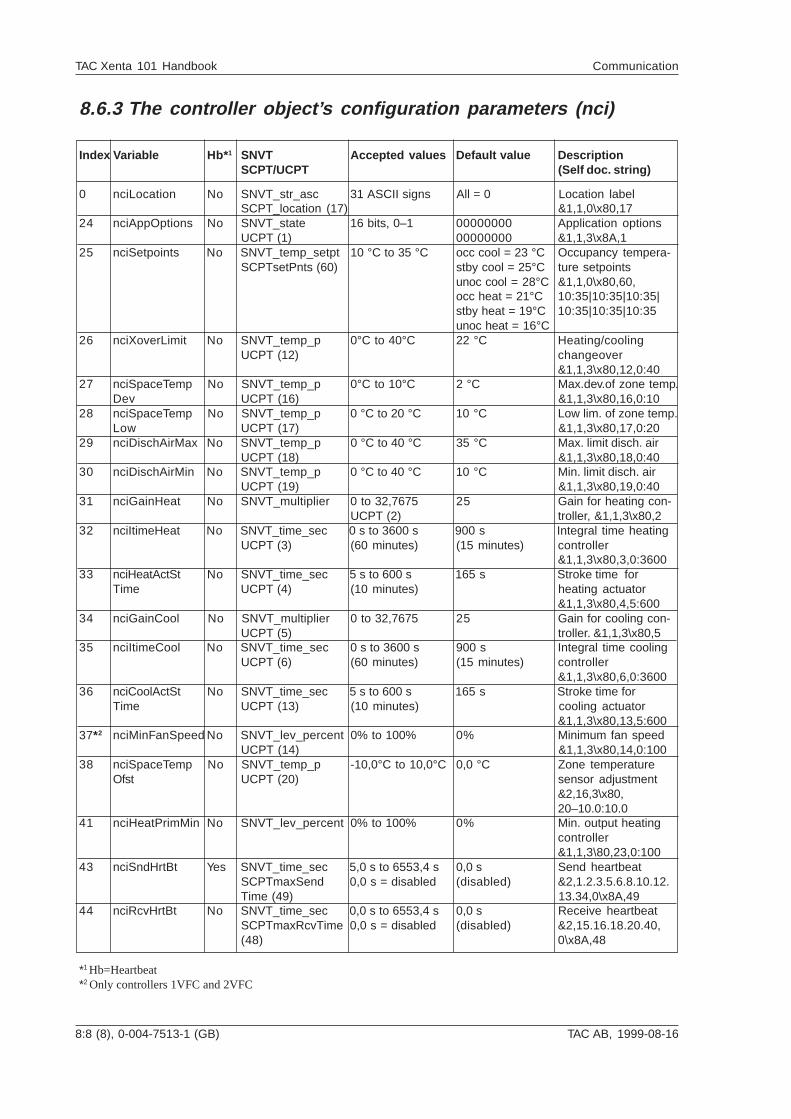
8:8 (8), 0-004-7513-1 (GB) TAC AB, 1999-08-16
TAC Xenta 101 Handbook Communication
8.6.3 The controller object’s configuration parameters (nci)
Index Variable Hb* 1 SNVT Accepted values Default value DescriptionSCPT/UCPT (Self doc. string)
0 nciLocation No SNVT_str_asc 31 ASCII signs All = 0 Location labelSCPT_location (17) &1,1,0\x80,17
24 nciAppOptions No SNVT_state 16 bits, 0–1 00000000 Application optionsUCPT (1) 00000000 &1,1,3\x8A,1
25 nciSetpoints No SNVT_temp_setpt 10 °C to 35 °C occ cool = 23 °C Occupancy tempera-SCPTsetPnts (60) stby cool = 25°C ture setpoints
unoc cool = 28°C &1,1,0\x80,60,occ heat = 21°C 10:35|10:35|10:35|stby heat = 19°C 10:35|10:35|10:35unoc heat = 16°C
26 nciXoverLimit No SNVT_temp_p 0°C to 40°C 22 °C Heating/coolingUCPT (12) changeover
&1,1,3\x80,12,0:4027 nciSpaceTemp No SNVT_temp_p 0°C to 10°C 2 °C Max.dev.of zone temp.
Dev UCPT (16) &1,1,3\x80,16,0:1028 nciSpaceTemp No SNVT_temp_p 0 °C to 20 °C 10 °C Low lim. of zone temp.
Low UCPT (17) &1,1,3\x80,17,0:2029 nciDischAirMax No SNVT_temp_p 0 °C to 40 °C 35 °C Max. limit disch. air
UCPT (18) &1,1,3\x80,18,0:4030 nciDischAirMin No SNVT_temp_p 0 °C to 40 °C 10 °C Min. limit disch. air
UCPT (19) &1,1,3\x80,19,0:4031 nciGainHeat No SNVT_multiplier 0 to 32,7675 25 Gain for heating con-
UCPT (2) troller, &1,1,3\x80,232 nciItimeHeat No SNVT_time_sec 0 s to 3600 s 900 s Integral time heating
UCPT (3) (60 minutes) (15 minutes) controller&1,1,3\x80,3,0:3600
33 nciHeatActSt No SNVT_time_sec 5 s to 600 s 165 s Stroke time forTime UCPT (4) (10 minutes) heating actuator
&1,1,3\x80,4,5:60034 nciGainCool No SNVT_multiplier 0 to 32,7675 25 Gain for cooling con-
UCPT (5) troller. &1,1,3\x80,535 nciItimeCool No SNVT_time_sec 0 s to 3600 s 900 s Integral time cooling
UCPT (6) (60 minutes) (15 minutes) controller&1,1,3\x80,6,0:3600
36 nciCoolActSt No SNVT_time_sec 5 s to 600 s 165 s Stroke time forTime UCPT (13) (10 minutes) cooling actuator
&1,1,3\x80,13,5:60037*2 nciMinFanSpeed No SNVT_lev_percent 0% to 100% 0% Minimum fan speed
UCPT (14) &1,1,3\x80,14,0:10038 nciSpaceTemp No SNVT_temp_p -10,0°C to 10,0°C 0,0 °C Zone temperature
Ofst UCPT (20) sensor adjustment&2,16,3\x80,20–10.0:10.0
41 nciHeatPrimMin No SNVT_lev_percent 0% to 100% 0% Min. output heatingcontroller&1,1,3\80,23,0:100
43 nciSndHrtBt Yes SNVT_time_sec 5,0 s to 6553,4 s 0,0 s Send heartbeatSCPTmaxSend 0,0 s = disabled (disabled) &2,1.2.3.5.6.8.10.12.Time (49) 13.34,0\x8A,49
44 nciRcvHrtBt No SNVT_time_sec 0,0 s to 6553,4 s 0,0 s Receive heartbeatSCPTmaxRcvTime 0,0 s = disabled (disabled) &2,15.16.18.20.40,(48) 0\x8A,48
*1 Hb=Heartbeat*2 Only controllers 1VFC and 2VFC
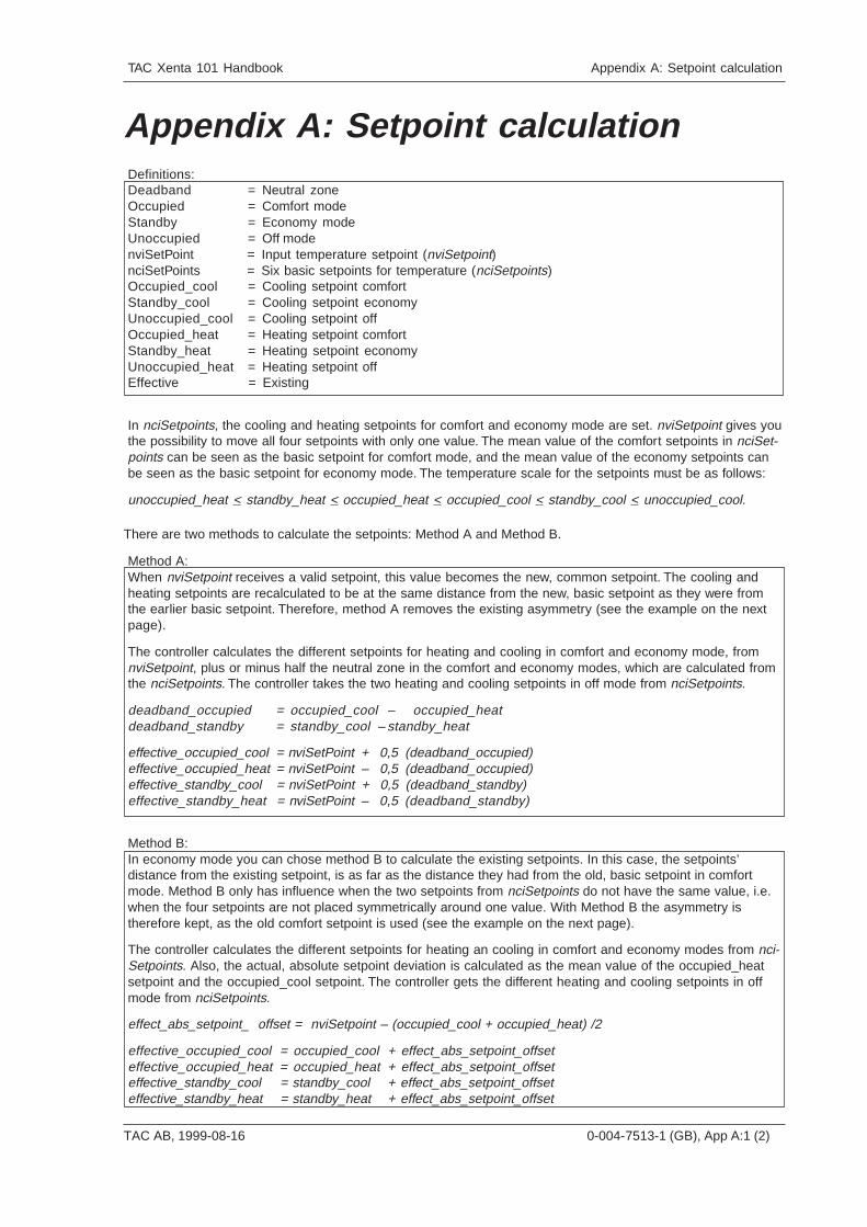
TAC Xenta 101 Handbook Appendix A: Setpoint calculation
TAC AB, 1999-08-16 0-004-7513-1 (GB), App A:1 (2)
Appendix A: Setpoint calculationDefinitions:Deadband = Neutral zoneOccupied = Comfort modeStandby = Economy modeUnoccupied = Off modenviSetPoint = Input temperature setpoint (nviSetpoint)nciSetPoints = Six basic setpoints for temperature (nciSetpoints)Occupied_cool = Cooling setpoint comfortStandby_cool = Cooling setpoint economyUnoccupied_cool = Cooling setpoint offOccupied_heat = Heating setpoint comfortStandby_heat = Heating setpoint economyUnoccupied_heat = Heating setpoint offEffective = Existing
In nciSetpoints, the cooling and heating setpoints for comfort and economy mode are set. nviSetpoint gives youthe possibility to move all four setpoints with only one value. The mean value of the comfort setpoints in nciSet-points can be seen as the basic setpoint for comfort mode, and the mean value of the economy setpoints canbe seen as the basic setpoint for economy mode. The temperature scale for the setpoints must be as follows:
unoccupied_heat < standby_heat < occupied_heat < occupied_cool < standby_cool < unoccupied_cool.
There are two methods to calculate the setpoints: Method A and Method B.
Method A:When nviSetpoint receives a valid setpoint, this value becomes the new, common setpoint. The cooling andheating setpoints are recalculated to be at the same distance from the new, basic setpoint as they were fromthe earlier basic setpoint. Therefore, method A removes the existing asymmetry (see the example on the nextpage).
The controller calculates the different setpoints for heating and cooling in comfort and economy mode, fromnviSetpoint, plus or minus half the neutral zone in the comfort and economy modes, which are calculated fromthe nciSetpoints. The controller takes the two heating and cooling setpoints in off mode from nciSetpoints.
deadband_occupied = occupied_cool – occupied_heatdeadband_standby = standby_cool – standby_heat
effective_occupied_cool = nviSetPoint + 0,5 (deadband_occupied)effective_occupied_heat = nviSetPoint – 0,5 (deadband_occupied)effective_standby_cool = nviSetPoint + 0,5 (deadband_standby)effective_standby_heat = nviSetPoint – 0,5 (deadband_standby)
Method B:In economy mode you can chose method B to calculate the existing setpoints. In this case, the setpoints’distance from the existing setpoint, is as far as the distance they had from the old, basic setpoint in comfortmode. Method B only has influence when the two setpoints from nciSetpoints do not have the same value, i.e.when the four setpoints are not placed symmetrically around one value. With Method B the asymmetry istherefore kept, as the old comfort setpoint is used (see the example on the next page).
The controller calculates the different setpoints for heating an cooling in comfort and economy modes from nci-Setpoints. Also, the actual, absolute setpoint deviation is calculated as the mean value of the occupied_heatsetpoint and the occupied_cool setpoint. The controller gets the different heating and cooling setpoints in offmode from nciSetpoints.
effect_abs_setpoint_ offset = nviSetpoint – (occupied_cool + occupied_heat) /2
effective_occupied_cool = occupied_cool + effect_abs_setpoint_offseteffective_occupied_heat = occupied_heat + effect_abs_setpoint_offseteffective_standby_cool = standby_cool + effect_abs_setpoint_offseteffective_standby_heat = standby_heat + effect_abs_setpoint_offset
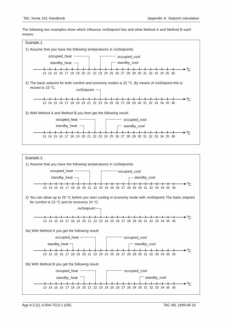
App A:2 (2), 0-004-7513-1 (GB) TAC AB, 1999-08-16
TAC Xenta 101 Handbook Appendix A: Setpoint calculation
The following two examples show which influence nviSetpoint has and what Method A and Method B eachmeans.
3635343332313029282726252423222120191817161514Co
13
occupied_heat
standby_heat
occupied_cool
standby_cool
3635343332313029282726252423222120191817161514Co
13
occupied_cool
standby_cool
occupied_heat
standby_heat
3635343332313029282726252423222120191817161514Co
13
nviSetpoint
1) Assume that you have the following temperatures in nciSetpoints:
3) With Method A and Method B you then get the following result:
2) The basic setpoint for both comfort and economy modes is 22 °C. By means of nviSetpoint this ismoved to 23 °C.
3a) With Method A you get the following result:
3b) With Method B you get the following result:
2) You can allow up to 29 °C before you start cooling in economy mode with nviSetpoint. The basic setpointfor comfort is 22 °C and for economy 24 °C.
1) Assume that you have the following temperatures in nciSetpoints:
Example 2.
3635343332313029282726252423222120191817161514Co
13
nviSetpoint
3635343332313029282726252423222120191817161514Co
13
occupied_cool
standby_cool
occupied_heat
standby_heat
3635343332313029282726252423222120191817161514Co
13
occupied_heat
standby_heat
occupied_cool
standby_cool
3635343332313029282726252423222120191817161514Co
13
occupied_heat
standby_heat
occupied_cool
standby_cool
Example 1.
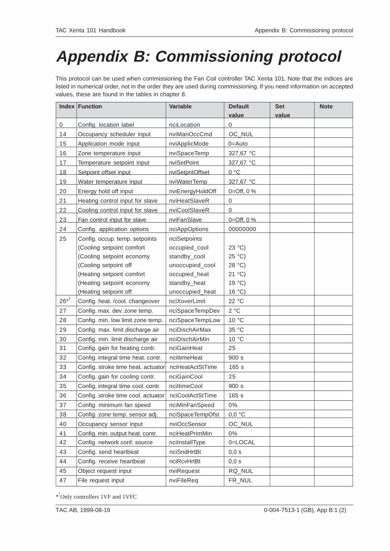
TAC AB, 1999-08-16 0-004-7513-1 (GB), App B:1 (2)
TAC Xenta 101 Handbook Appendix B: Commissioning protocol
*1Only controllers 1VF and 1VFC
This protocol can be used when commissioning the Fan Coil controller TAC Xenta 101. Note that the indices arelisted in numerical order, not in the order they are used during commissioning. If you need information on acceptedvalues, these are found in the tables in chapter 8.
Appendix B: Commissioning protocol
Index Function V ariable Default Set Note
value value
0 Config. location label nciLocation 0
14 Occupancy scheduler input nviManOccCmd OC_NUL
15 Application mode input nviApplicMode 0=Auto
16 Zone temperature input nviSpaceTemp 327,67 °C
17 Temperature setpoint input nviSetPoint 327,67 °C
18 Setpoint offset input nviSetpntOffset 0 °C
19 Water temperature input nviWaterTemp 327,67 °C
20 Energy hold off input nviEnergyHoldOff 0=Off, 0 %
21 Heating control input for slave nviHeatSlaveR 0
22 Cooling control input for slave nviCoolSlaveR 0
23 Fan control input for slave nviFanSlave 0=Off, 0 %
24 Config. application options nciAppOptions 00000000
25 Config. occup. temp. setpoints nciSetpoints
(Cooling setpoint comfort occupied_cool 23 °C)
(Cooling setpoint economy standby_cool 25 °C)
(Cooling setpoint off unoccupied_cool 28 °C)
(Heating setpoint comfort occupied_heat 21 °C)
(Heating setpoint economy standby_heat 19 °C)
(Heating setpoint off unoccupied_heat 16 °C)
26*1
Config. heat. /cool. changeover nciXoverLimit 22 °C
27 Config. max. dev. zone temp. nciSpaceTempDev 2 °C
28 Config. min. low limit zone temp. nciSpaceTempLow 10 °C
29 Config. max. limit discharge air nciDischAirMax 35 °C
30 Config. min. limit discharge air nciDischAirMin 10 °C
31 Config. gain for heating contr. nciGainHeat 25
32 Config. integral time heat. contr. nciItimeHeat 900 s
33 Config. stroke time heat. actuator nciHeatActStTime 165 s
34 Config. gain for cooling contr. nciGainCool 25
35 Config. integral time cool. contr. nciItimeCool 900 s
36 Config. stroke time cool. actuator nciCoolActStTime 165 s
37 Config. minimum fan speed nciMinFanSpeed 0%
38 Config. zone temp. sensor adj. nciSpaceTempOfst 0,0 °C
40 Occupancy sensor input nviOccSensor OC_NUL
41 Config. min. output heat. contr. nciHeatPrimMin 0%
42 Config. network conf. source nciInstallType 0=LOCAL
43 Config. send heartbeat nciSndHrtBt 0,0 s
44 Config. receive heartbeat nciRcvHrtBt 0,0 s
45 Object request input nviRequest RQ_NUL
47 File request input nviFileReq FR_NUL
App B:2 (2), 0-004-7513-1 (GB) TAC AB, 1999-08-16
TAC Xenta 101 Handbook Appendix B: Commissioning protocol
Blank page
TAC AB, 1999-08-16 0-004-7513-1 (GB), Reg:1 (2)
TAC Xenta 101 Handbook Index
Index
A
Alarm 5:15Ambient temperature 7:1Appendix A: Setpoint calculationAppendix B: Commissioning
protocol
B
Basic parameters 4:1Bound network variables 3:11Bypass key 2:3Bypass mode 5:3
C
Cable lengths 3:3Calculation 5:6Cascade control 5:12Comfort mode 5:2Commissioning 3:9Communication 8:1Communication possibilities 2:2Configuration parameters 4:1Configuration parameters (nci/
nvi’s) 3:11Connection terminals 3:4Control example 2:4Control sequence with one valve
output (controllers 1VF 5:8Controller object 8:4Controller’s basic functions 5:2
D
Data sheets for ZS 101–ZS 105 2:3
Dimensions 7:3Documentation 1:2
E
Electrical installation 3:3Energy consumption 7:1
F
Fan control 5:10Fan control and monitoring via
network 5:10Fast flashing 2:3Fitting 3:1Forcing the controller 5:4
Free-standing operation 3:12Frost protection 5:15Functional description 5:1
G
”Guide-lines for zonesystems” 2:2
H
Heartbeat 8:2Housing 7:1Humidity 7:1
I
Inputs and outputs (nvi/nvo’s) 6:2
Installation 3:1
L
LNS 1:3LonWorks™ 2:2
M
Master/slave operation 5:16Measuring zone temperature 5:6Mechanical installation 3:1Menu tree 8:1More about functions 2:1Min. value for heating
valve 5:14
N
nciAppOptions 4:1nciRcvHrtBt 4:1nciSndHrtBt 4:1Network installation 3:11Network management tool 3:11Network variables (index) 5:1neuron 1:3node 1:3Node object 8:3Node object configuration para-
meters (nci) 8:4Node object inputs (nvi) 8:3Node object outputs (nvo) 8:4Node status 3:10Normal settings and power
on 8:1Not accepted values 8:3nvoAlarmStatus 5:15
O
Occupancy sensor 5:13On/off control 5:10Operation modes 5:2Other configuration para-
meters 4:3Out, light 2:3
P
Power supply 7:1Problems and solutions 6:3
R
Red light emitting diode 2:3
S
Safety norm 3:3Self documentatory string 8:1Service pin 1:3Setpoint calculation 5:6Setpoint knob 2:3Slowly flashing 2:3Snap the controller onto a DIN
rail 3:1Speed control 5:10Steady light 2:3
T
Technical data 7:1Terminology 1:3Trouble-shooting 6:1
W
Wall modules 2:3Wall modules ZS 101–ZS
104 3:4Window contact 5:13Wink 1:3Wiring of TAC Xenta 101-
1VF 3:5Wiring of TAC Xenta 101-
1VFC 3:6Wiring of TAC Xenta 101-
2VF 3:7Wiring of TAC Xenta 101-
2VFC 3:8With semi-protection 7:3Without semi-protection 7:3
Reg:2 (2), 0-004-7513-1 (GB) TAC AB, 1999-08-16
TAC Xenta 101 Handbook Index
Z
Zone temperature setpoints 5:6Zone controller TAC Xenta 101-
1VF 2:4Zone controller TAC Xenta 101-
1VFC 2:5Zone controller TAC Xenta 101-
2VF 2:5Zone controller TAC Xenta 101-
2VFC 2:6
TAC AB, 1999-08-16
TAC Xenta 101 Handbook Reply form
You can help make this manual even better!Please help us make our documentation as good as possible. Use this form to let us know of anyerrors, unclear descriptions or suggested improvements.
Send the form to: Or e-mail to:
TAC AB [email protected]ägershillgatan 18SE-213 75 MALMÖSWEDEN
I have found the following errors and/or unclear descriptions in the “Xenta 101 Handbook”(part number 0-004-7513-0 (GB)):
On page:...................................................................................................................................................
..................................................................................................................................................................
..................................................................................................................................................................
I suggest the following improvements:
On page: ...................................................................................................................................................
..................................................................................................................................................................
..................................................................................................................................................................
Name: Company:
TAC AB, 1999-08-16
TAC Xenta 101 Handbook Reply form

TAC AB, 1999-08-16
TAC Xenta 101 Handbook Reply form

TAC AB, 1999-08-16
TAC Xenta 101 Handbook Reply form
TAC AB, Jägershillgatan 18, SE-213 75 MALMÖ, SWEDEN, +46 40 38 68 50 (switchboard)