Embed Size (px)
Citation preview
YOUR ONE -STOP SOURCE OF ELECTRONICS INFORMATION 08559
OCTOBER 1985 $1.95 CANADA $2.50
THE MAGAZINE FOR ELECTRONICS & COMPJ r ER ENTHUSIASTS
New Technology
NEW, QUIETER FM STEREO BROADCAST SYSTEM
Construction Project
ADVANCED FURNACE CONTROLLER BOOSTS HEATING EFFICIENCY
First Impressions Commodore's Wonder Computer: The Amiga Epson's LX -80 Printer Ericsson's Portable PC
TM
h4.,.
Sharp VHS Hi- = VCR Evaluated (p. 10)
Projects & Applications Measure Temperature with Any Voltmeter Practical Op -Amp Circuits A Testbench Audio Amplifier Switchyr Cures Computer Clutter Experiment with Sound- Detection Circuits
Permit No. 79
U.S. Postage Paid
Gordonsville, VA 22942
't% - Project 'AeaE ures Tempera-ure \Vith A iy Voltmeter t;p. 50)
Also in :his issue: Testing Sharp's Newest Hi -Fi VCR and Juki's $295 Letler-Guality Printer ... Lancaster Discusses Computerized Cubic Splines for Drawinç Freeform Curves ... Examining DX- Propagation Commodore -64 Software ... Latest Electronic /Computer Products & Nevis ... and more.
THE ANSWER TEK DUAL TRACE OSCILLOSCOPES BY ANY MEASURE
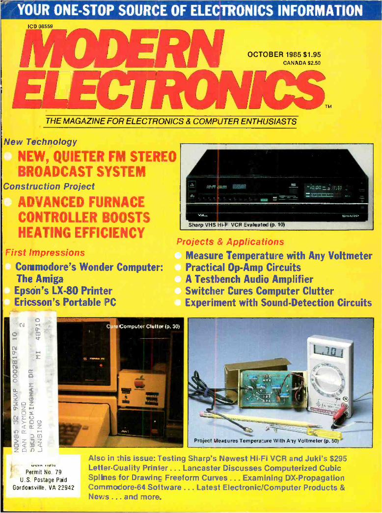
Now! Tek quality and expert advice are just a free phone call away!
The industry standard in CRT performance. Crisp, easy -to- read, bright CRT; 14kV accelerating potential, provides high writing rate and small spot size. Full size 8x10 cm display for measurement accuracy.
Display controls are flexible and easy to use. Sep- arate intensity controls reduce blooming in alter- nate sweep mode. Focus tracking minimizes control adjustment and BEAM FIND elimi- nates confusion.
Vertical sys- tem provides measurement assurance. Flat transient response and high accuracy ensures true reproduction of your signals. Fast risetime and high bandwidth is well suited for a variety of measurement.
Perform delayed sweep measure- ments accurately and easily. Both sweeps can be displayed alter- nately making dif- ferential measure- ments easy and accurate (1 %). An interlocking SEC /DIV control simplifies set -up.
Stable hands -off triggering. P -P AUTO detects sig- nal peaks, then sets the trigger level for you. Dis- play asynchronous signals using VERT MODE trig- gering. Indepen- dent TV field and line selection.
Front panel laid out by function for ease of use. Color coding aids the user in opera- tion. Functions and modes are placed logically. All nomenclature is clearly labeled, and protected behind a scratch - less Lexan surface.
Our direct order line gets you the industry's leading price /performance portables... and fast answers from experts! The 60 MHz single time base delay 2213A, the 60 MHz dual time base 2215A and the 100 MHz dual time base 2235 offer unprecedented reliability and affordability, plus the industry's first 3 -year warranty* on labor and parts, CRT included.
The cost: just $1275 for the 2213A, $1525 for the 2215A, $1750 for the 2235.t Even at these low prices, there's no scrimping on performance. You
have the bandwidth for digital and analog circuits. The sensitivity for low signal measurements. The sweep speeds for fast logic fami- lies. And delayed sweep for fast, accurate timing measurements. All scopes are UL Listed and CSA approved.
You can order, or obtain literature, through the Tek National Marketing Center. Tech- nical personnel, expert in scope applications, will answer your questions and expedite delivery. Direct orders include comprehen- sive 3 -year warranty *, operator's
manual, two 10X probes, 15 -day return policy and worldwide ser- vice backup.
Order toll free: 1- 800 -426 -2200, Ask for Rick. In Oregon, call collect: (503) 627 -9000. Or write Tektronix, Inc. P.O. Box 1700 Beaverton, OR 97075
Tektronix [.(IMMI I 1 1 f l f 1 I 1 i1 I I l 1 NI:I
Copyright 0 1985, Tektronix, Inc. All rights reserved. #TTA- 439 -3. tPrice F.O.B. Beaverton, OR. *3 -year warranty includes CRT.
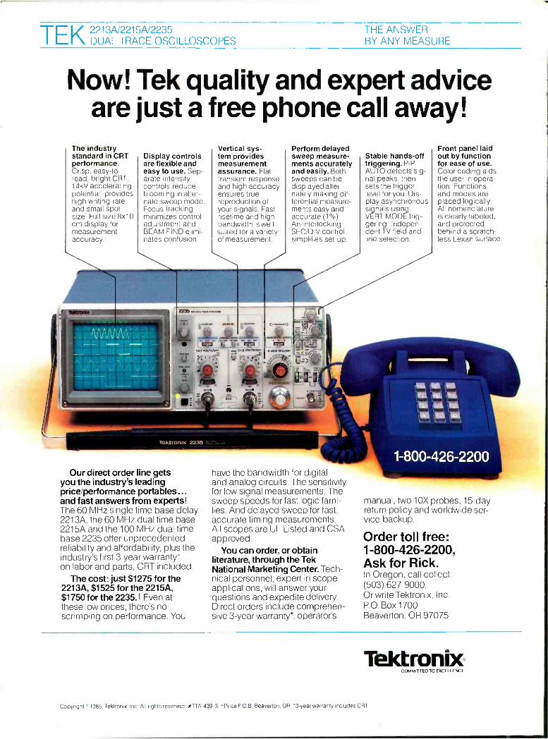
Where's Your ELECTRONICS Career Headed?
The Move You Make Today Can Shape Your Future Yes it's your move. Whether on a chess board or in your career, you should plan each move carefully. In electronics, you can move ahead faster and further with a
B. S. DEGREE Put professional knowledge and a COLLEGE DEGREE in your electronics career. Earn your degree through independent study at home, with Grantham College of Engineering. No commuting to class. Study at your own pace, while continuing your present job.
The accredited Grantham non -traditional degree program is intended for mature, fully employed workers who want to upgrade their careers . . . and who can successfully study electronics and supporting subjects through
INDEPENDENT STUDY, AT HOME
Independent Home Study Can Prepare You
Study materials, carefully written by the Gran- tham staff for independent study at home, are supplied by the College, and your technical questions related to those materials and the lesson tests are promptly answered by the Gran- tham teaching staff.
Recognition and Quality Assurance Grantham College of Engineering is accredited by the Accrediting Commission of the National Home Study Council.
All lessons and other study materials, as well as com- munications between the college and students, are in the English language. However, we have students in many foreign countries; about 80% of our students live in the United States of America.
r- -1 Grantham College of Engineering M-10-85
1
Free Details Available from: 0570 Humbolt Street, Los Alamitos, CA 90720
Please mail me your free catalog which explains your B.S. Degree independent -study program.
Grantham College of Engineering Name Age
10570 Humbolt Street Address
Los Alamitos, California 90720 City State Zip
ELECTRONICS RN
THE MAGAZINE FOR ELECTRONICS & COMPUTER ENTHUSIASTS
OCTOBER 1985
Hartford
1
+MERIDEN 1 Norwich
New London
LEGET
aven
14
30
4 13 12 11 1
2 3 4 5 6
(C) 324 QUAD OP AMP
26
50
VOLUME 2, NUMBER 4
FEATURES
14 Stereo FM That's as Quiet as Mono New development promises FM stereo reception as good as present -day mono. By Len Feldman
26 Using Op Amps Practical applications of the op amp in various circuits. By Robert A. Witte
30 Cure Computer Clutter Project lets you switch between color TV and video monitor, Koala Pad and joystick on Apple Ile. By Jeffrey I. Lackey
38 An Advanced Oil- Furnace Controller All- electronic controller conserves fuel and handles timing. By Duane M. Perkins
50 A °C/ °F Thermometer Accessory Construction project lets you measure temperatures with any voltmeter. By Bill Owen
56 Testbench Audio Amplifier Build a simple, inexpensive amplifier for your test - bench or modify for other audio needs. By C.R. Fischer
PRODUCT EVALUATIONS
10 Sharp Model VC -5F7Ú VHS Hi -Fi VCR By Stan Prentiss
86 Juki Model 6000 Daisywheel Printer By Joseph Peters
DEPARTMENTS
4 Editorial Our First Milestone. By Art Salsberg
5 Letters 6 Modern Electronics News
8 New Products 58 Electronics Notebook
Detecting Sound. By Forrest M. Mims III
62 Hardware Hacker Secrets of Cubic Splines and more. By Don Lancaster
70 PC Papers First Impressions: Epson LX -80, Ericsson Portable PC & Commodore Amiga. By Eric Grevstad
76 Software Focus The Computerized DX Edge. By John Richardson
78 Communications SW Station News & Schedule Updates. By Glenn Hauser
85 Books & Literature
96 Advertisers Index
2 / MODERN ELECTRONICS / October 1985
EDITORIAL STAFF Art Salsberg
Editor -in -Chief Alexander W. Burawa
Managing Editor Dorothy Kehrwieder Production Manager
FJizabeth Ryan Art Director
Barbara Scully Artist
Pat Le Blanc Richard Kishanuk Phototypographers
Hal Keith Illustrator
Larry Mulvehill Photographer
Leonard Feldman, Glenn Hauser, Don Lancaster, Forrest Mims III, Stan Prentiss, Charles Rubenstein
Contributing Editors
BUSINESS STAFF Richard A. Ross
Publisher Art Salsberg
Associate Publisher Dorothy Kehrwieder
General Manager Anthony C. Sparacino Newsstand Sales Director
Arlene Caggiano Accounting
Cheryl Chornicki Subscriber Services
SALES OFFICES Modern Electronics 76 North Broadway Hicksville, NY 11801
(516) 681 -2922
Eastern Advertising Representative Paul McGinnis Company
60 East 42nd Street New York, NY 10017
(212) 490-1021 Midwest Advertising Representative
Market /Media Associates 435 Locust Road
Wilmette, IL 60091 (312) 251 -2541 Ted Rickard
Western Advertising Representative JE Publishers Representatives
6855 Santa Monica Blvd., Suite 200 Los Angeles, CA 90038
(213) 467-2266 Jay Eisenberg, Director
San Francisco: (415) 864 -3252 Denver: (303) 595 -4331
Offices: 76 North Broadway, Hicksville, NY 11801. Tet ephone: (516) 681 -2922. Modern Electronics (ISSN 0748-
9889) is published monthly by Modern Electronics, Inc.
Application to mail at second class rates pending at
Hicksville, NY and other points. Subscription prices
(payable in US Dollars only): Domestic - one year S 16.97,
two years 531.00, three years 545.00; Canada /Mexico -one year 519.00, two years S35.00, three years S51.00;
Foreign - one year 521.00, two years 539.00, three years
557:00. Foreign Air Mail - one year 574.00, two years
5145.00, three years $216.00. Entire contents copyright 1985 by Modern Electronics, Inc. Modern Electronics or Modern Electronics, Inc. as-
sumes no responsibility for unsolicited manuscripts. Al- low six weeks for delivery of first issue and for change of address. Printed in the United States of America. Postmaster: Please send change of address notice to
Modern Electronics, Inc., 76 North Broadway, Hicks- ville, NY 11801.
ftadue Ihaek Parti Plaee® Over 1000 Items in Stock at Everyday Low Prices
We Have the Connectors You Need for Computer Interfacing
Solder -Type Subminiature "D" Connectors. Ideal for building your own RS -232 cables. Fig. Type Positions Cat. No. Each
1 Sub -D Male 25 276 -1547 2.99 2 Sub -D Female 25 276 -1548 3.99 3 Hood for Above 25 276 -1549 1.99
(4) Dustcaps. For Sub D 25 connectors. Help pre - vent moisture and dirt contamination. One ma e and one female. 276 -1546 Set 39¢
MONA 6
(5) Printer Connector. NEW LOW PRICE! 34- position solder -type connector for parallel printers. Heavy -duty metal -shielded construction for trouble - free service. Was $6.99. 276 -1534 4 99 (6) 6- Position DIN Plug. Fits joystick port of Tandy Color Computer 2. Use with inline jack to build your own joystick extension cord. 274 -020 1 19 (7) 6- Position Inline DIN Socket. For use with 6- pin DIN plug. 274 -021 99C
We Can Replace Virtually Any Entertainment or
Industrial Semiconductor
RADIO SHACK'S NEW
SPECIAL -ORDER SERVICE
If the IC or semiconductor you need is not part of our regular stock, our store manager will help you get it. He'll identify a suitable replacement, then special -order it from our warehouse. There's no postage to pay or other extra charges for this con- venient service!
CMOS and TTL Digital ICs
All Include
I Pin -Out and Specs
CMOS Cat. No. Each 4001 276 -2401 .99 4011 276-2411 .99 4013 276 -2413 1.19 4017 276 -2417 1.49 4049 276 -2449 1.19 4066 276-2466 1.19
TTL Cat. No. Each 7400 276 -1801 .89 7404 276 -1802 .99 7408 276 -1822 1.29 7447 276 -1805 1.69 7490 276 -1808 1.19
Computer Interface ICs
Type Cat. No. Each
MC1488 RS232 Quad Line Driver 276 -2520 1.79 MC1489 RS232 Quad Line Receiver 276 -2521 1.79 MOC3010 Triac -Output Optocoupler 276 -134 1.99
Check These Super Values!
9
(8) Small Enclosure and PC Board. A real bar- gain! The 13/16 x 37/1s x 25/16" enclosure is of rug- ged, yet easy -to -drill plastic. Internal PC board has 483 DIP- spaced solder- ringed holes. Two labels, hardware, snap -in rubber feet. 270 -291 ... 2.99 (9) 4" 120 VAC Cooling Fan. Whisper quiet and efficient. Moves heat away from computers, ham and hi -fi equipment. Also useful in solar heat sys- tems. 65 CFM. Leads for easy hookup. 411/16 x 411/16 x 21/2': U.L. recognized. 273 -241 15.95 (10) Electronic "Doorbell" Chime. Gives you the familiar "ding -dong" sound and it operates from one "D" cell. 43/4 "leads. 273 -067 ... 6.95
Voltage Regulator ICs
Type Function Cat. No. Each 7805 5 VDC Fixed 276 -1770 1.59 7812 12 VDC Fixed 276 -1771 1.59 7815 12 VDC Fixed 276 -1772 1.59
LM317T' 1.2 to 27 VDC 276 -1778 2.79 LM723 0 to 40 VDC 276 -1740 .99
14 -Pin DIP, others TO -220 case
Switch Values
11
(11) Rotary Switch. 2 -pole, 6- position. Rated 0.3 amp at 125 VAC. Single deck, non- shorting type.
1 /4 " -diamt pr shaft. 275 -1386 1 19 (12) NEW! 120 VAC SPDT Push -On /Push -Off. Round button. Rated 3 amps at 120 VAC. Lamp requires 12 volts, AC or DC. 1/2" mtg. hole. 275 -677 4 95
Voice Synthesizer IC
Heart of a Rewarding
Project!
SP0256 -AL2. This MOS LSI device uses a pro- gram stored in its built -in 16K ROM to synthesize natural sounding speech. Requires low -cost sup- port components and is easy to interface with most microcomputers. Requires 3.12 MHz clock crystal (available through Radio Shack). 28 -pin DIP with detailed specs and programming data. 5 VDC, sin- gle supply. 276 -1784 12.95
Learn About Electronics By Building Your Own Circuits
Only 249
Getting Started in Electron- ics. By Forrest Mims III. The perfect introduction to the ex- citing world of ICs and solid - state. It's written in easy -to- understand language by one of America's most popular technical au- thors. Features large schematic diagrams with cleanly labeled component values. 128 pages. 276 -5003 2 49
'VS.'i
Semiconductor Reference
Half Price! Reg. e
9 3.4 1985 Edition 272 Pages Illustrated
Exclusive substitution sec- tion lists over 80,000 semi types and their low -cost Radio Shack equivalents. Data on Radio Shack ICs, SCRs, LEDs diodes and opto devices. 276 -4008 Sale 1.75
TV RF Modulator
COL Only
Special urchase!
495
Compare our LOW price to mail - order offers on this high -quality de- vice! Originally for TI 99/4 computer, this prewired, metal -cased module provides a superior -quality TV signal on channel 3 or 4. 5 -pin DIN plug accepts video, audio and 12 VDC power input. Extra -long cable for easy hookup. With data. 277 -1015 4 95
Pocket -Size, 8 -Range Multitester
Saves 207
888 Reg. 10.95
Switched Ranges
2000 ohms -per -volt sensitivity, yet only 31/2x21/4x11/4 "and super durable. Ranges: AC and DC volts 0 -15, 0 -150, 0 -1000. DC current to 150 milliamps. Resistance to 100,000 ohms. With leads, manual. Requires "AA" battery. 22 -212 Sale 8.88
Digital Logic Probe With Tone Output s
1995 Overload Protected
The fast way to "peek inside" TTL, LS and CMOS digital circuits. Color - coded LEDs indicate high, low or pulsed logic states (up to 10 MHz). The simultaneous tone output frees your eyes for faster testing. With illus- trated instructions and user's tips. 22 -302 19.95
Sale! IC Inserter and Extractor Set
Cut 30%
488 Reg. 6.95
Handle DIP ICs The Safe Way
This easy -to -use set helps you re- move or install DIP ICs without bend- ing pins. The inserter features a built -in pin straightener. Both of the tools are groundable to protect static - sensitive MOS devices. 276 -1574 Sale, Set 4.88
Over 1000 items in stock: Binding posts, Books, Breadboards, Buzzers, Capacitors, Chokes, Clips, Connectors, Fuses, Hardware, ICs, Jacks, Knobs, Lamps, Multitesters, PC Boards, Plugs, Rectifiers,
NileRelays, Resistors, Switches, Tools, Transformers, Transistors, Wire, Zener Diodes, and more!
(1RC 1 .F. 380s, FREE IVFORM:1, 11(N (':AR1)
Radie jhack A DIVISION OF TANDY CORPORATION iiii,
Prices .,piIy .1? pad, i{,nlii,y RAflio Shack aid, , dr,t1 ,1,;,I,,}
Quick charge cordless soldering iron- Jp to 125 electronics jcin :s per charge. Total recharge in less than 4 hoLrs. Isolated tip des g`I. One of more than 2 dozer ISO -TIP and ORYX rons available. Wri:e for free catalog and reine of nearest distrixr..tor.
A Hot Tip on Cordless Soldering
No. '700 QUICK CHARGE
Cordless Soldering !ron
I
ORYX® WAHL CLIPPER CORPORATION Sterling, Illinois E10E1 (815) 62`ó525
CIR(1 F fia ON FRET INFORMATION CARO
Computer problems?
DON'T BLAME THE SOFTWARE! Isolators prevent:
CPU /printer /disk interaction Lightning or spike damage AC power Fine dîlsturbances RFI -EMI interference
Pat. #1.259.7115
Commercial Grade Isolators IS04 3 Isolated Sockets ISO-2 2 Isolated Socket Banks, 6 Sockets
Industrial Grade Isolators ISO-3 3 Double Isolated Sockets ISO-11 2 Double Isolated Banks, 6 Sockets
Laboratory Grade Isolators ISO- 17 4 Quad Isolated Sockets ISO-18 2 Quad Isolated Banks, 6 Sockets
$ 81.95 $ 81.95
$122.95 $122.95
$213.95 $180.95
Circuit Breaker, any model (Add.CB) Add $ 11.00
Remote Switch. any model (Add -RS) Add $ 20.0()
L37 Electronic Specialists, Inc. 171 S. Main St., :Sox 389, Natick, Mess. 01780 (617) 855-1532
Toll Fr ee Order Desk 1 -800- 225 -4878 MasterCard. VISA, American Express
CIRO I. F 2705 FRF}. INFORMATION CARD
4 / MODERN ELECTRONICS / October 1985
111111/EDITORIAL I/Ii1 Our First Milestone
Starting our second year of publication with this issue gives us some special pleasure. After all, the publishers of Popular Elec-
tronics had considered active electronics /computer hardware en- thusiasts to be virtually an archaic sect . It's clear that this is not so, judging from our responsive readers and growing number of ad- vertisers.
Not that it's been easy, but sweet life is born in pain. We recently added 37,000 readers who formerly subscribed to
defunct Computers & Electronics, PE's short -lived later name. They had previously subscribed to PE, so have a strong affinity for electronics. As a result, we've had an opportunity to read some letters from these people that were sent to C &E's circulation department. A sample here captures the essence of many others:
"I don't want more computer -only magazines. My original subscription was for Electronics. A few months after renewal of Electronics you switched to Computers & Electronics (a minimum of electronics)!!! I wrote cancelling my subscrip- tion, which was ignored...." Most of these new Modern Electronics readers are also into
computers, but want electronics as well, with more emphasis on the latter. MODERN ELECTRONICS was conceived to serve such technically oriented people, the majority of whom are in- volved professionally in some area of electronics.
With 12 issues under our belts, we reflected on the past year's publishing effort while working on this one. During our first one - year period we published a total of 747 pages of editorial matter or an average of 62'/ pages per issue plus covers and advertisements. This is a healthy editorial package that compares favorably with that of other technically oriented magazines established many years longer.
Our editorial mix spans the electronics world: Electronic pro- jects and tutorials lead, of course. In the feature article area, it
constituted 51.8% of the editorial matter. General technical pro- duct articles accounted for another 25.2 %, while computers (in- cluding computer- oriented projects) garnered 23.1% coverage.
Our columns and departments make up about 40% of the edi- torial material presented every month. These include Forrest Mims's "Electronics Notebook" electronic experiments, Don Lancaster's "Hardware Hacker," Eric Grevstad's "PC Papers," "New Products," "News," "Product Evaluations," and so on. To distinguish between the two, look for an author's byline or the absence of one. Columnists are identified, and their opinions and conclusions are solely their own; departments such as "New Products" are written in house.
An article index, October 1984 through December 1985, will be included in our year-end December issue. Back copies can be or- dered at $2.50 each. Also, should any readers like to write articles for Modern Electronics, ask us for our Author's Guide (enclose a stamped, self- addressed envelope).
We try to touch all bases every issue and believe we have a happy mix of electronics and computer information. You're the final ar- biter, though. Any suggestions or expressions of likes and dislikes are always most welcome. We'll take them all into account as we
continuously fine -tune the magazine. So let's hear from you.
Will/ill/LETTERS/il/if A Happy Discovery
I was most happy to discover your (rela- tively) new magazine on the stands. It's good to see all of those familiar names on the masthead and in the table of con - tents-so good that I've sent in a sub- scription order.
Jamie E. Hanrahan San Diego, CA
Correction In your July 1985 issue you show a sche-
matic drawing of a portable gas detector. If you look a little closer you'll see that when Si is closed there is a direct short between V + and ground.
The foil pattern is correct. Hopefully most of your readers used the PC board and did not wire -wrap this project.
R.D. Payne Salinas, CA
The V+ line in Fig. 1 should come down the anode side of the LEDs and terminate at pin 9 of IC 1. It should not continue on to the ground connection as shown. The pc guide in Fig. 2 is correct. -Ed.
Lancaster Booster Once again, here's a note to say you
folks are right on. Editorial slant is even better than P.E. in its time. Don L. is wonderful- comments on Laserwriter compatibility, etc.
Nicholas Bodley New York, NY
Down with page 53! Here's one vote against the acceptance
of future ads such as that on page 53 of the July 1985 issue. One can only assume the "Hacknet" ad is what it purports to be and doesn't represent a "sting" operation. Therefore, this ad for a service "... dedi- cated to computer intrusion ... and soft- ware piracy ..." isn't the sort of business with which you should associate, regard- less of the advertising revenue generated.
Michael Meyers Montclair, NJ
I am shocked by the appearance of the ad on p. 53 [Hacknet] of your July issue. Placing an ad for such an organization is nothing short of an endorsement for the illegal and unwanted access they so proudly proclaim.
Ren J. Tescher Williston, ND
We agree. The ad slid in at the last pro- duction moment. It will not be accepted again. -Ed.
Mid -East Video Fan Your magazine has more break-
throughs than Popular Electronics ever introduced in a single year. I read an arti- cle on Videocassettes in your May issue, and there you mentioned the latest play - only VCR made by a South Korean Com- pany, the Goldstar Electronics, the top - loading model VCP -400M, which carries a suggested retail price of $349.95 each. As a consumer I would like to know if there is any local distributor of the above product including video enhancer, chro- ma compensator, stabilizer, fader, and modulator, here in SAUDI ARABIA. If there weren't any, I only wish that you would recommend a best selection and the distributor's addresses.
Edgardo P. Generoso Buraidah Water Treatment Plant
Al- Motta, Buraidah, Gassim Kingdom of Saudi Arabia
Write to Goldstar Electronics, 1050 Wall St. West, Lyndhurst, NJ 07071. -Ed.
REPLANG FIVE BELTS AT ONCE IS SMARTER THAN
ONE ATATIME. It makes sense for your customers. And dollars for you. Sooner or later, every VCR belt needs replacing. And when one goes, the others aren't far behind. So make the most of it
4 with RCA's VCR Belt Kits (stock numbers
199094 and 199095) for RCA, Magnavox, Panasonic, Quasar,
Sylvania, and other VCRs. You'll save customers the expense of extra repair trips and make extra profit for yourself replacing all the belts at once.
The smart money's on RCA, for a whole line of VCR replacement parts and accessories. See your RCA VCR Parts Distributor or for more information, write: RCA Distributor and Special Products Division, Deptford, N.J. 08096- 2088. Attn: Sales Promotion Services.
CIRCLE 37 ON FREE INFORMATION CARD
RC,' VCR Parts
October 1985 / MODERN ELECTRONICS / 5
!lllltMODERN ELECTRONICS NEWS 1111/111
BORLAND SELLS MILLIONTH SOFTWARE PACKAGE. In only about two years since its start, Borland International announced it sold its millionth computer software package. The company's star rose sharply with the introduction of its low -cost desktop utility program, Side - Kick, a set of popup windows that can be called up in the middle of an applications program. As a result, it moved to new, larger facil- ities; 32,000 sq. ft. compared to its former 8,000 sq. ft.
FLOPPY DISK CAMERA. Konica unveiled a prototype still video system recently with a 2.2 lb. camera that uses a 1.85" floppy disk to store images. A prototype video player was revealed, too, that plays back the disk's recordings, either single or continuous frames, as well as a hard -copy printer.
COMMODORE'S AMIGA COMPUTER BOWS. The Amiga personal computer, a $1295 machine (excluding monitor) that promises to challenge Apple's Macintosh, was demonstrated in all its colorful graphics glory to a large croup of press people. Using the same Motorola 68000 CPU, its operation is faster than Mac's and can accommodate more user memory, as well as fea- turing full color performance. The desktop icons, windows, and mouse are all there. With Digital Research's GEM software giving IBM PC's and compatibles Mac -like operation, there are now three systems in this exciting design area.
SIR CLIVE BITES DUST. Sir Clive Sinclair gave up controlling interest in Sinclair Research as bills piled up during a soft computer -sales market this year. The company's QL computer has not yet been marketed in the U.S. except for one mail -order source. Sir Clive is still with the company, however, as "Lifetime President" and research consultant.
SWITCHING TRANSISTOR SPEED RECORD. Honeywell's Physical Science Center developed what's said to be the fastest semiconductor switching tran- sistor ever made, with current travelling between 25 GaAs transistor gates in a record 11.6 trillionths of a second. A self -aligned gate technique was used, depositing a larger amount of ions into the source and drain regions.
AUTOMATIC VEHICLE LOCATION. A mobile -to -fixed system available from Motorola provides accurate vehicle location up to 1 /8th of a mile. It uses the Federal Government's existing LORAN -C network, and a low frequency transmission system infrastructure. The system's database accommodates up to 2,000 street intersections and 200 user -defined sites.
VIDEOCASSETTE MOVIE VENDING MACHINES. Vending machines for videocassette movies have been introduced by Video Vendor, Skokie, IL. The machine underwent tests at a 7- Eleven store, where the maker says hundreds of customers are already using it. The machine takes cash (dollar bills, five -dollar bills or quarters) and can display up to 320 different movie cassettes for rent, virtually a wall of cassettes. Customers fill out an application listing their credit card's information. To rent a movie, a key pad is used to enter an account number and the number of the movie to be rented. After depositing appropriate charge, say, $2, the cassette is said to be "vended" in about 25 seconds. Video Vendor is being sold for $7,500. Might be the Eighties equivalent of the 24- hour laundromat business.
6 / MODERN ELECTRONICS / October 1985
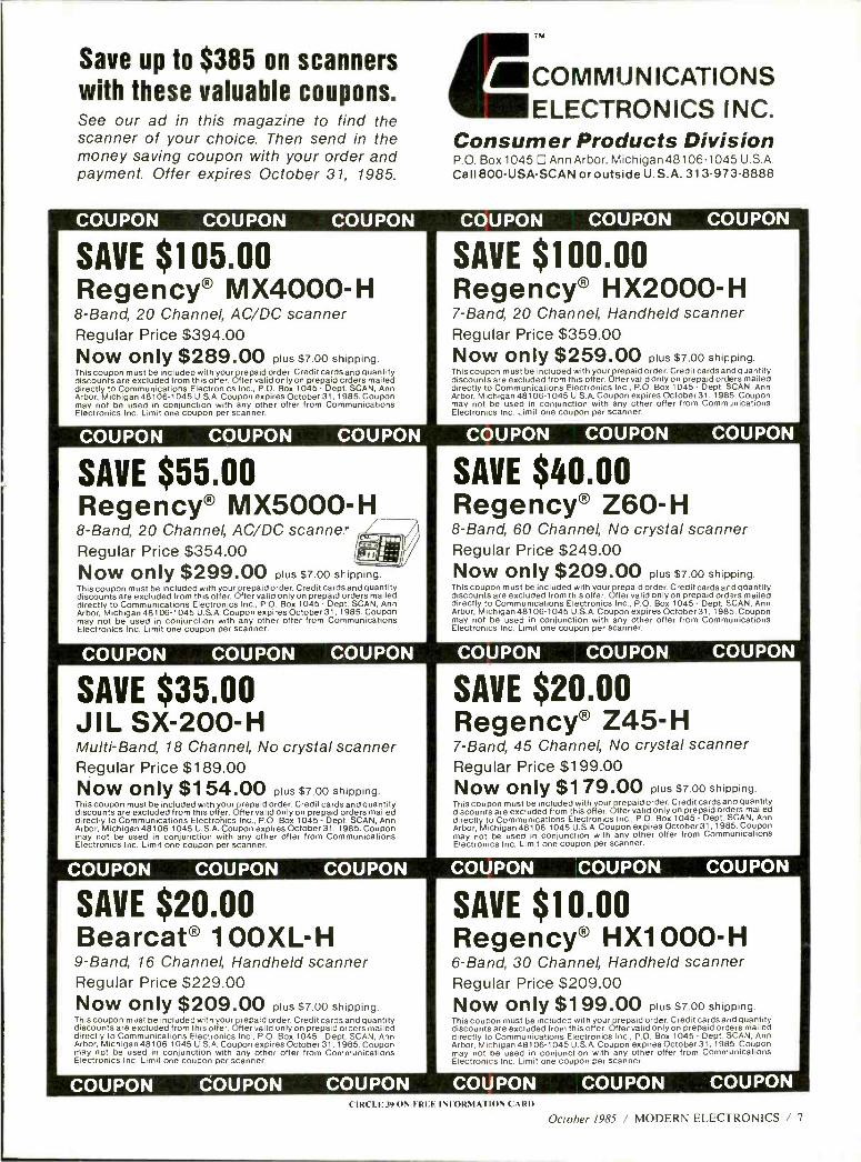
Save up to $385 on scanners with these valuable coupons. See our ad in this magazine to find the scanner of your choice. Then send in the money saving coupon with your order and payment. Offer expires October 31, 1985.
TM
/COMMUNICATIONS ELECTRONICS INC.
Consumer Products Division P.O. Box 1045 D Ann Arbor, Michigan 48106.1045 U.S.A. Call 800- USA -SCAN or outside U.S.A. 313-973-8888
COUPON COUPON COUPON
SAVE $105.00 Regency® MX4000 -H 8 -Band, 20 Channel, AC /DC scanner Regular Price $394.00 Now only $289.00 plus $7.00 shipping. This coupon must be included with your prepaid order. Credit cardsand quantity discounts are excluded from this offer. Offer valid only on prepaid crders mailed directly to Communications Electronics Inc., P.O. Box 1045 - DepL SCAN, Ann Arbor, Michigan 48106 -1045 U.S.A. Coupon expires October31, 1985. Coupon may not be used in conjunction with any other offer from Communications Electronics Inc. Limit one coupon per scanner.
COUPON COUPON COUPON
SAVE $55.00 Regency® MX5000 -H 8 -Band, 20 Channel, AC /DC scanner Regular Price $354.00 Now only $299.00 plus $7.00s1-ippjng. This coupon must be included with your prepaid order. Credit cards and quantity discounts are excluded from this offer. Offer valid only on prepaid orders mailed directly to Communications Electronics Inc., P.O. Box 1045 - Dept. SCAN, Ann Arbor, Michigan 48106 -1045 U.S.A. Coupon expires October 31, 1985. Coupon may not be used in conjunction with any other offer from Communications Electronics Inc. Limit one coupon per scanner.
COUPON COUPON COUPON
SAVE $35.00 J I L SX-200-H Multi -Band, 18 Channel, No crystal scanner Regular Price $189.00 Now only $154.00 plus $7.00 shipping. This coupon must be included with your prepaid order. Credit cards and quantity discounts are excluded from this offer. Offer valid only on prepaid orders mailed directly to Communications Electronics Inc., P.O. Box 1045 - Dept. SCAN, Ann Arbor, Michigan 48106 -1045 U.S.A. Coupon expires October 31, 1985. Coupon may not be used in conjunction with any other offer from Communications Electronics Inc. Limit one coupon per scanner.
COUPON COUPON COUPON
SAVE $20.00 Bearcat® 100X L- H 9 -Band, 16 Channel, Handheld scanner Regular Price $229.00 Now only $209.00 plus $7.00 shipping. This coupon must be included with your prepaid order. Credit cards and quantity discounts are excluded from this offer. Offer valid only on prepaid orders mailed directly to Communications Electronics Inc., P.O. Box 1045 - Dept. SCAN, Ann Arbor, Michigan 48106 -1045 U.S.A. Coupon expires October31 , 1985. Coupon may not be used in conjunction with any other offer from Communications Electronics Inc. Limit one coupon per scanner.
COUPON COUPON COUPON
COUPON COUPON COUPON
SAVE $100.00 Regency® HX2000 -H 7 -Band, 20 Channel, Handheld scanner Regular Price $359.00 Now only $259.00 plus $7.00 shipping. This coupon must be included with your prepaid order. Credit cards and quantity discounts are excluded from this offer. Offer valid only on prepaid orders mailed directly to Communications Electronics Inc., P.O. Box 1045 - Dept. SCAN, Ann Arbor, Michigan 48106 -1045 U.S.A. Coupon expires October 31. 1985. Coupon may not be used in conjunction with any other offer from Comm Jnications Electronics Inc. Limit one coupon per scanner.
COUPON COUPON COUPON
SAVE $40.00 Regency® Z60 -H 8-Band, 60 Channel, No crystal scanner Regular Price $249.00 Now only $209.00 plus $7.00 shipping. This coupon must be included with your prepaid order. Credit cards and gbantity discounts are excluded from this offer. Offer valid only on prepaid orders mailed directly to Communications Electronics Inc., P.O. Box 1045 - Dept. SCAN. Ann Arbor, Michigan 48106-1045 U.S.A. Coupon expires October 31, 1985. Coupon may not be used in conjunction with any other offer from Communications Electronics Inc. Limit one coupon per scanner.
COUPON COUPON COUPON
SAVE $20.00 Regency® Z45 -H 7 -Band, 45 Channel, No crystal scanner Regular Price $199.00 Now only $179.00 plus $7.00 shipping. This coupon must be included with your prepaid order. Credit cards and quantity discounts are excluded from this offer. Offer valid only on prepaid orders mailed directly to Communications Electronics Inc., P.O. Box 1045 - Dept. SCAN, Ann Arbor. Michigan 48106 -1045 U.S.A. Coupon expires October31 , 1985. Coupon may not be used in conjunction with any other offer from Communications Electronics Inc. Limit one coupon per scanner.
COUPON COUPON COUPON
SAVE $10.00 Regency® HX1000 -H 6 -Band, 30 Channel, Handheld scanner Regular Price $209.00 Now only $199.00 plus $7.00 shipping. This coupon must be included with your prepaid order. Credit cards and quantity discounts are excluded from this offer. Offer valid only on prepaid orders mailed directly to Communications Electronics Inc., P.O. Box 1045 - Dept. SCAN, Ann Arbor, Michigan 48106-1045 U.S.A. Coupon expires October 31, 1985. Coupon may not be used in conjunction with any other offer from Communications Electronics Inc. Limit one coupon per scanner.
COUPON COUPON COUPON ( IRCLE39ON FREE INFORMA IION CARD
October 1985 / MODERN ELECTRONICS / 7
VIII NEW PRODUCTS ÍI
For more information on products described, please circle the appropri- ate number on the Free Information Card bound into this issue or write to the manufacturer.
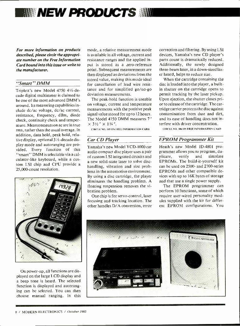
"Smart" DMM Triplett's new Model 4750 4'h -de- cade digital multimeter is claimed to be one of the most advanced DMM's around. Its measuring capabilities in- clude dc/ac voltage, dc/ac current, resistance, frequency, dBm, diode check, continuity check and temper- ature. Measurements on ac are in true rms, rather than the usual average. In addition, data hold, peak hold, rela- tive display, optional 3'h- decade dis- play mode and autoranging are pro- vided. Every function of this "smart" DMM is selectable via a cal- culator -like keyboard, while a cus- tom LSI chip and CPU provide a 25,000 -count resolution.
l
mode, a relative measurement mode is available in all voltage, current and resistance ranges and the applied in- put is stored as a zero -reference point. Subsequent measurements are then displayed as deviations from the stored value, making this mode ideal for cancellation of lead wire resis- tance and for simplified go /no -go deviation measurements.
The peak -hold function is useable on voltage, current and temperature measurements with the positive peak signal value stored for up to 12 hours. The Model 4750 DMM measures 7 "
x 3' /z " x 13/4 ".
CIRCLE NO. 105 ON FREE INFORMATION CARD
Car CD Player Yamaha's new Model YCD -1000 car audio compact disc player uses a pair of custom LSI integrated circuits and a new solid -state laser to solve disc - handling, vibration and size prob- lems in the automotive environment. By using a disc cartridge, the player eliminates the handling problem. A floating suspension removes the vi- bration problem.
One chip is for servo -control, laser focusing and tracking location. The other handles D/A conversion, error
correction and filtering. By using LSI devices, Yamaha's new CD player's parts count is dramatically reduced. Additionally, the newly designed three -beam laser, in a down -sized las- er heard, helps to reduce size.
When the cartridge containing the disc is loaded into the player, a built - in shutter on the cartridge opens to permit tracking by the laser pickup. Upon ejection, the shutter closes pri- or to release of the cartridge. The car- tridge carrier protects the disc against contamination from dust and dirt, and its ease of handling does not in- terfere with driver concentration.
CIRCLE NO. 106 ON FREE INFORMATION CARD
EPROM Programmer Kit Heath's new Model ID -4801 pro- grammer allows you to program, du- plicate, verify and simulate EPROMs. The build -it- yourself kit can be used on 2500- and 2700- series EPROMs and other compatible de- vices with up to 16K bytes of storage and that use a single power supply.
The EPROM programmer can perform 10 functions, some of which require user -wired personality mod- ules supplied with the kit for differ- ent EPROM configurations. You
On power -up, all functions are dis- played on the large LCD display and a beep tone is heard. The selected function is displayed and autorang- ing can be selected. You can then choose manual ranging. In this
8 / MODERN ELECTRONICS / October 1985
can load an EPROM with data stored in RAM and then verify the transfer. Data can also be loaded from an ex- isting EPROM into the program- mer's RAM. Also, the ID -4801 can be used to emulate ROM in an exter- nal device with connection of an ap- propriately wired cable.
Data can be transmitted and re- ceived between the programmer and a computer through an RS -232C ser- ial port equipped with a DB -25 con- nector. Data (in Intel hex format) transfer rate is 9600 baud. Informa- tion and mode entry are performed with a hex keypad that lets you select any memory address to examine, de- lete, change or enter data. Addresses can also be incremented and decre- mented, and RAM can be searched to locate one or two data bytes and dis- play data and memory address.
Contained in the ID -4801 are a 2K x 8 system ROM and 2K x 8 RAM, both of which can be expanded to 16K with optional add -ons. $349.95.
('IRCLE NO. 107 ON FREE INFORMATION CARD
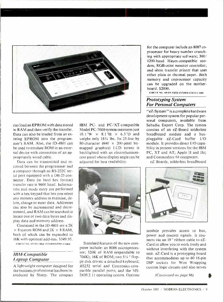
IBM - Compatible Laptop Computer A lightweight computer designed for the business professional has been in- troduced by Sharp. The compact
IBM PC- and PC /XT- compatible Model PC -7000 system measures just 16.1 "W x 8.1 "H x 6.3 "D and weighs only 183/4 lbs. Its 25 -line by 80- character (640 x 200 -pixel bit - mapped graphics) LCD screen is
backlighted with an electrolumines- cent panel whose display angle can be adjusted for best readability.
for the computer include an 8087 co- processor for heavy number crunch- ing with appropriate software; 300/ 1200 -baud Hayes -compatible mo- dem; RGB color monitor controller; and silent transfer printer that uses either plain or thermal paper. Both memory and coprocessor capacity can be upgraded on the mother - board. $2000.
CIRCLE NO. 108 ON FREE INFORMATION CARD
Prototyping System For Personal Computers "eZ- System" is a complete hardware development system for popular per- sonal computers, available from Sabadia Export Corp. The system consists of an eZ -Board solderless breadboard module and a bus - pluggable eZ -Card buffer I/O module. It provides direct I/O capa- bility in present versions for the IBM PC, XT and AT; Apple II and IIe; and Commodore 64 computers.
eZ Boards, solderless breadboard
Standard features of the new com- puter include: an 8086 microproces- sor; 320K of RAM (expandable to 704K); 16K of ROM; two 51/4 " flop- py disk drives; a detached keyboard; RS232 serial and Centronics -com- patible parallel ports; and the MS- DOS 2.11 operating system. Options
module provides access to bus, power and control signals. It con- nects via an 18 " ribbon cable to eZ- Card to allow you to work freely and without interfering with the system unit. eZ -Card is a protoyping board that accommodates up to 60 16 -pin DIP sockets for Wire Wrapping custom logic circuits and also serves
(Continued on page 96)
October 1985 / MODERN ELECTRONICS / 9
11111IIfPRODUCT EVALUATIONS AMMO Video /Audio
Sharp Model VC -5F7U VHS Hi -Fi VCR: Better - Than -Average Video & Great Hi -Fi Sound
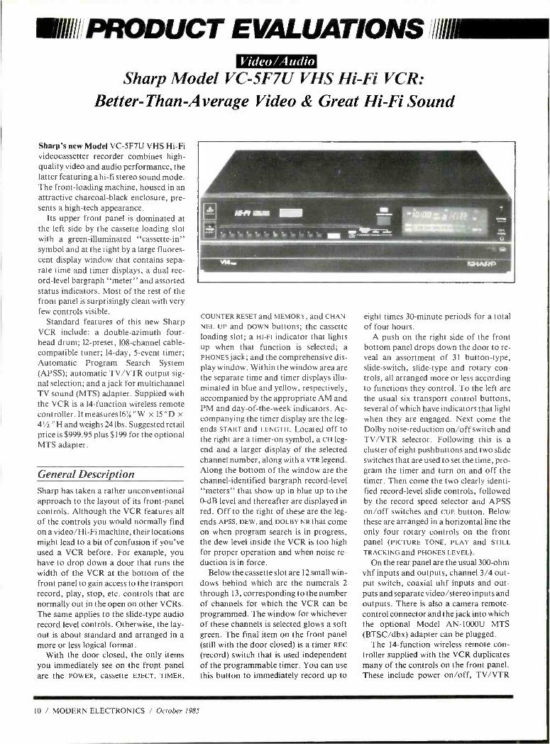
Sharp's new Model VC -SF7U VHS Hi -Fi videocassetter recorder combines high - quality video and audio performance, the latter featuring a hi -fi stereo sound mode. The front -loading machine, housed in an attractive charcoal -black enclosure, pre- sents a high -tech appearance.
Its upper front panel is dominated at the left side by the cassette loading slot with a green -illuminated "cassette -in" symbol and at the right by a large fluores- cent display window that contains sepa- rate time and timer displays, a dual rec- ord -level bargraph "meter" and assorted status indicators. Most of the rest of the front panel is surprisingly clean with very few controls visible.
Standard features of this new Sharp VCR include: a double -azimuth four - head drum; 12- preset, 108 -channel cable - compatible tuner; 14 -day, 5 -event timer; Automatic Program Search System (APSS); automatic TV /VTR output sig- nal selection; and a jack for multichannel TV sound (MTS) adapter. Supplied with the VCR is a 14- function wireless remote controller. It measures 16/, "W x 15 "D x 4'/ " H and weighs 24 lbs. Suggested retail price is $999.95 plus $199 for the optional MTS adapter.
General Description Sharp has taken a rather unconventional approach to the layout of its front -panel controls. Although the VCR features all of the controls you would normally find on a video /Hi -Fi machine, their locations might lead to a bit of confusion if you've used a VCR before. For example, you have to drop down a door that runs the width of the VCR at the bottom of the front panel to gain access to the transport record, play, stop, etc. controls that are normally out in the open on other VCRs. The same applies to the slide -type audio record level controls. Otherwise, the lay- out is about standard and arranged in a more or less logical format.
With the door closed, the only items you immediately see on the front panel are the POWER, cassette EJECT, TIMER,
COUNTER RESET and MEMORY, and CHAN-
NEL UP and DOWN buttons; the cassette loading slot; a HI -Fl indicator that lights up when that function is selected; a PHONES jack; and the comprehensive dis- play window. Within the window area are the separate time and timer displays illu- minated in blue and yellow, respectively, accompanied by the appropriate AM and PM and day -of- the -week indicators. Ac- companying the timer display are the leg- ends START and LENGTH. Located off to the right are a timer -on symbol, a CH leg- end and a larger display of the selected channel number, along with a VTR legend. Along the bottom of the window are the channel- identified bargraph record -level "meters" that show up in blue up to the 0 -dB level and thereafter are displayed in red. Off to the right of these are the leg- ends APSS, DEW, and DOLBY NR that come on when program search is in progress, the dew level inside the VCR is too high for proper operation and when noise re- duction is in force.
Below the cassette slot are 12 small win- dows behind which are the numerals 2
through 13, corresponding to the number of channels for which the VCR can be programmed. The window for whichever of these channels is selected glows a soft green. The final item on the front panel (still with the door closed) is a timer REC
(record) switch that is used independent of the programmable timer. You can use this button to immediately record up to
eight times 30- minute periods for a total of four hours.
A push on the right side of the front bottom panel drops down the door to re- veal an assortment of 31 button -type, slide- switch, slide -type and rotary con- trols, all arranged more or less according to functions they control. To the left are the usual six transport control buttons, several of which have indicators that light when they are engaged. Next come the Dolby noise -reduction on /off switch and TV /VTR selector. Following this is a cluster of eight pushbuttons and two slide switches that are used to set the time, pro- gram the timer and turn on and off the timer. Then come the two clearly identi- fied record -level slide controls, followed by the record speed selector and APSS on /off switches and CUE button. Below these are arranged in a horizontal line the only four rotary controls on the front panel (PICTURE TONE, PLAY and STILL
TRACKING and PHONES LEVEL).
On the rear panel are the usual 300 -ohm vhf inputs and outputs, channel 3/4 out- put switch, coaxial uhf inputs and out- puts and separate video /stereo inputs and outputs. There is also a camera remote - control connector and the jack into which the optional Model AN -1000U MTS (BTSC /dbx) adapter can be plugged.
The 14- function wireless remote con- troller supplied with the VCR duplicates many of the controls on the front panel. These include power on /off, TV /VTR
10 / MODERN ELECTRONICS / October 1985
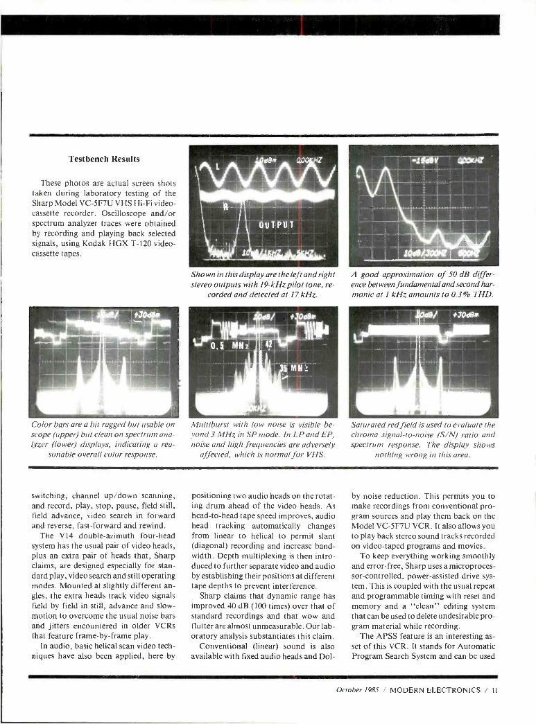
Testbench Results
These photos are actual screen shots taken during laboratory testing of the Sharp Model VC -5F7U VHS Hi -Fi video- cassette recorder. Oscilloscope and /or spectrum analyzer traces were obtained by recording and playing back selected signals, using Kodak HGX T -120 video- cassette tapes.
Shown in this display are the left and right stereo outputs with 19 -kHz pilot tone, re-
corded and detected at 17 kHz.
A good approximation of 50-dB differ- ence between fundamental and second har- monic at 1 kHz amounts to 0.3% THD.
Color bars are a bit ragged but usable on scope (upper) but clean on spectrum ana- lyzer (lower) displays, indicating a rea-
sonable overall color response.
Multiburst with low noise is visible be- yond 3 MHz in SP mode. In LP and EP, noise and high frequencies are adversely
affected, which is normal for VHS.
Saturated red field is used to evaluate the chroma signal -to -noise (S /N) ratio and spectrum response. The display shows
nothing wrong in this area.
switching, channel up /down scanning, and record, play, stop, pause, field still, field advance, video search in forward and reverse, fast -forward and rewind.
The V14 double -azimuth four -head system has the usual pair of video heads, plus an extra pair of heads that, Sharp claims, are designed especially for stan- dard play, video search and still operating modes. Mounted at slightly different an- gles, the extra heads track video signals field by field in still, advance and slow - motion to overcome the usual noise bars and jitters encountered in older VCRs that feature frame -by -frame play.
In audio, basic helical scan video tech- niques have also been applied, here by
positioning two audio heads on the rotat- ing drum ahead of the video heads. As head -to -head tape speed improves, audio head tracking automatically changes from linear to helical to permit slant (diagonal) recording and increase band- width. Depth multiplexing is then intro- duced to further separate video and audio by establishing their positions at different tape depths to prevent interference.
Sharp claims that dynamic range has improved 40 dB (100 times) over that of standard recordings and that wow and flutter are almost unmeasurable. Our lab- oratory analysis substantiates this claim.
Conventional (linear) sound is also available with fixed audio heads and Dol-
by noise reduction. This permits you to make recordings from conventional pro- gram sources and play them back on the Model VC -5F7U VCR. It also allows you to play back stereo sound tracks recorded on video -taped programs and movies.
To keep everything working smoothly and error -free, Sharp uses a microproces- sor- controlled, power- assisted drive sys- tem. This is coupled with the usual repeat and programmable timing with reset and memory and a "clean" editing system that can be used to delete undesirable pro- gram material while recording.
The APSS feature is an interesting as- set of this VCR. It stands for Automatic Program Search System and can be used
October 1985 / MODERN ELECTRONICS / II
PRODUCT EVALUATIONS .. Sharp Model VC -5F7U continued .. .
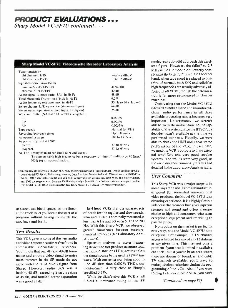
Sharp Model VC -5F7U Videocassette Recorder laboratory Analysis
Tuner sensitivity vhf channels 3/10 uhf channels 15/30
Signal -to -noise ratios (S /N) luminance (SP /LP /EP) chroma (SP /LP /EP)
Audio signal -to -noise ratio (S /N) in Hi -Fi Total Harmonic Distortion (THD) in Hi -FI Audio frequency response max. in Hi -Fi Stereo channel L/R separation (sine -wave input) Stereo signal separation (stereo input, Dolby on) Wow and flutter (NAB at 3 kHz /CCIR weighted)
SP LP EP
Tape speeds Recording /playback times Ac operating range Ac power required at 120V
record playback
NOTES: Dolby engated for audio S/N and stereo. To convert MHz high frequency luma response to "lines, MHz for an approximation.
- 6/ -8 dBmV -7/-5 dBmV
41/40 dB 40 dB 48 dB 0.3% 30 Hz to 20 kHz, - 6
64 dB 25 dB
0.003% 0.003% 0.0035% Normal for VHS Up to 8 hours 100 to 130 V ac
27.48 W rms 27.12 W rms
" multiply by 80 lines
Test equipment: Tektronix Models 7L5, 7L12 spectrum analyzers; Hameg Model HM605 oscilloscope; Sa- delco Model FS -3D VU field strength meter; Data Precision Models 945 and 1750 multimeters; B &K -Pre- cision 1260 NTSC color /multiburst and 3020 sweep function generators, 1035 Wow and Flutter meter, and 2007 stereo generator; Sencore VA48 video analyst (modified); a Sultzer resistance- coupled oscilla- tor; Kodak T -120 HGX videocassette; and RCA Model FLR -2622T TV receiver /monitor.
to search out blank spaces on the linear audio track to let you locate the start of a program without having to shuttle the tape back and forth.
Test Results This VCR gave us some of the best audio and video response results we've found in comparable videocassette recorders. You'll note that our 41- and 40 -dB lumi- nance and chroma video signal -to -noise measurements in the SP mode do not agree with the rated 50 -dB figure from Sharp. However, audio S/N was a healthy 48 dB, exceeding Sharp's rating of 45 dB, and nominal stereo separation was a good 25 dB.
In 4 -head VCRs that use separate sets of heads for the regular and slow speeds, wow and flutter is nominally measured at less than 6 Hz and between 6 Hz and 200 Hz. With this Sharp VCR, we observed greater similarities between measure- ments at all speeds (see Laboratory Anal- ysis table).
Spectrum -analyzer or meter- measur- ing devices do not produce accurate total harmonic distortion (THD) results unless the signal source being used is a pure sine wave. With our generator being good to - 55 dB (less than 0.002% THD), our measurement is very close to Sharp's specified 0.3 %.
While we didn't give this VCR a full
3.5 -MHz luminance rating in the SP
mode, resolution did approach this excel- lent figure. However, the falloff to 2.8 MHz in the EP mode didn't exactly com- plement the better SP figure. On the other hand, when tape speed is reduced to one - third of normal, both S/N and rolloff at high frequencies are usually adversely af- fected in all VCRs, though the deteriora- tion is far more pronounced in cheaper machines.
Considering that the Model VC -5F7U is touted as both a video and an audio ma- chine, audio performance in all three available processing modes becomes very important. Unfortunately, we weren't able to check the multichannel sound cap- ability of the system, since the BTSC /dbx decoder wasn't available at the time we performed out tests. Happily, we were able to check the Hi -Fi and linear stereo performance of the VCR. In each case, we used the VCR's outputs to drive exter- nal amplifiers and very good speaker systems. The results were very good, as shown in our spectrum -analyzer tests and detailed in the Laboratory Analysis table.
User Comment
This Sharp VCR was a major surprise in more ways than one. From a manufactur- er noted for somewhat unexceptional video products, the Model VC -5F7U is an elevating experience. It is a highly flexible videocassette recorder that gives superior pictures and sound and offers a major choice to high -end consumers who want exceptional equipment and are willing to pay the price.
No product on the market is perfect in every way, and the Model VC -5F7U is no exception. For example, its TV channel access is limited to a mix of any 12 stations at any given time. This may not pose a problem if your area is limited in available channels, but if you're in an area where there are dozens of broadcast and cable TV channels available, you'll have to make judicious selections during the pro- gramming of the VCR. Also, if you want to plug a camera into the VCR, you can't
(Continued on page 86)
12 / MODERN ELECTRONICS / October 1985
How Many Times Do You Intend To Let
"THE SAME DOG" Bite You ?
* Now many times have you worked all day long trying to diagnose the hi- voltage / LV regulator circuit of a set that is in shut down only to eventually find that a shorted video, color, vertical, tuner, AGC, or matrix circuit was causing the set to shut down and, to find that the hi- voltage / LV regulator circuit was working flawlessly all the time?
* How many times have you spent the day looking for a short that was causing the set to shut down, only to eventually find that an open vertical, video, matrix circuit or, an open HV multiplier was to blame?
* How many times have you worked all day on the same TV set, only to find out that the set's flyback transformer was defective?
* How many flyback transformers have you replaced only to find that the original flyback was not defective?
* How many horiz output transistors and Sony SG 613 SCRs have you destroyed while simply trying to figure out whether the flyback was good or bad?
* How many times have you been deceived by your flyback "ringer "? Can you even count the number of hours that your "ringer" has caused you lo waste?
* How many times have you condemned a flyback, only to find that a shorted scan derived B + source was causing the flyback to "appear" as though it were defective?
* How many hours have you wasted, working on a TV set, only to find that the CRT had a dynamically shorted 2nd anode (to primary element)?
* How many new sweep transformers have you unknowingly destroyed because a short existed in one of the scan derived B+ sources?
* How many times have you said to yourself, "I could fix this - - - -thing if I could only get it to fire up long enough to lite the screen? - - - without blowing an output transistor or a fuse . "
* How many additional bench jobs could you have gotten, had you been able to give an accurate, "on the spot" estimate on sets that were either in shut down or, not capable of coming on long enough for you to analyze them?
If you had been using our all new Super Tech HV circuit scanner, you would have had an accurate evaluation concerning all of the above in about one minute, at the push of just one single button.
It's true! Push just one test button and our HV circuit scanner will (1) Accurately prove or disprove the flyback, (2) Check for any possible shorts in any circuit that utilizes scan derived B + , (3) Check the scan derived power supplies themselves for shorted diodes and / or elec- trolytic capacitors, (4) Check for primary B + collector voltage and, (5) Check the horiz output stage for defects.
Our HV circuit scanner works equally well on sets with integrated or outboard HV multipliers. It will diagnose any brand, any age, solid state TV set including Sony. The only exceptions are sets which use an SCR for trace and, another for retrace (i.e., RCA CTC 40 etc.). Our scanner will not work on these sets.
In plain English, our HV circuit scanner is even easier to operate than a "plain vanilla" voltmeter.
First off, when you're using a scanner, you do not remove the flyback in order .to check it. In fact, you don't even unhook any of the wires that are connected to the flyback! All you do is:
(1) Remove the set's horiz output device, plug in the scanner's inter- face plug, then make one single ground connection. That's all you do to hook it up.
(2) If the primary LV supply is functional and, assuming that the emitter circuit of the horiz output stage has continuity, the scanner will tell you that it is ready to "scan" by illuminating the "ready" light, which is the while button on the test / run switch.
(3) Press the spring loaded (test) side of the test / run switch and the scanner will "look" for any type of a short that might exist anywhere on the secondary side of the flyback, including the HV multiplier, any circuit that relies on flyback generated B+ and, including the flyback itself (both primary and all secondary windings). It will simultaneously check for a shorted LV regulator device HV multiplier, or an open or "partially" open safety capacitor.
If a short or, an "excessive load" exists on one secondary winding, all other secondary windings will have "normal" output voltage in spite of the short. Only the shorted winding itself will have zero volts on it. This makes shorted scan derived B + sources incredibly easy to isolate. During this test, the 2nd anode voltage is being limited to approx 5 kv by the scanner.
If a short is present, the red "flyback" light will either lite, or flash (at various speeds), depending on which type of a short exists. If no shorts exist, the "flyback" light will be green.
Assuming that the "flyback" light is green, no shorts exist and, it is now time (and safe), to begin looking for open circuits which might be causing the set to shut down due to flyback run -a -way. It only stands to reason that if no shorted conditions exist, then one (or more) circuits will have to be open, otherwise, the TV set would be working!
(4) Now that you know that no shorts exists, push the "run" side of the test / run switch (the side that latches). Provided all of the other circuits in the TV set are functional, the scanner will now put a picture on the set's CRT screen that has full vertical and horiz deflection, normal audio, video and color.
Keep in mind that during this test, your scanner is:
(1) Circumventing all horiz osc /driver related shut down circuits, (2) Limiting the set's 2nd anode voltage to approx 20-25 kv, (3) Substituting the set's horiz osc /driver circuit and, as a result, eliminating any need that the set might have for an initial start up or B+ resupply circuit for the osc /driver.
Wait about 15 seconds for its filaments to warm up, then look at the CRT. Any circuits that are "open" will now produce an obvious symp- tom on the screen. Because the scanner has circumvented all of the set's shut down features, you can now use your old reliable "symptom to circuit analysis" technique to troubleshoot the problem, i.e., if the picture has no blue in it - - - repair the blue video or blue matrix circuit. If the picture has only partial vertical deflection - - - repair the vertical circuit, and so on. The scanner has effectively removed all of the stumbling blocks that would normally prevent you from diagnosing the problem. i.e., start up and shut down features, and allowed you to repair the TV set by using conventional techniques.
When you're using a scanner, all start up, shut down, dead set pro- blems are easy to solve. You don't need anyone to tell you just how dif- ficult these problems can be for those who don't have a scanner!!
Our Super Tech HV circuit scanner normally sells for only $49500.
VISA, MASTERCHARGE, C.O.D. ORDERS WELCOME
DIEHL ENGINEERING 6004 Estacado Ln. Amarillo, TX 79109
PHONE (806) 359 -1824 or (806) 359 -0329 Phone Orders Welcome
Since the Scanner only has two buttons to press, most technicians never need it but, our "Hot Line" is available to assist new owners in the operation of their scanner. Phone (806) 359 -0320.
CIRCLE 43 ON FREE INFORMATION CARD

EurmoracsMWERN October 1985
Stereo FM That's As Quiet As Mono
A new circuit development promises FM stereo reception with greatly improved signal -to -noise performance
By Len Feldman
ack in 1961, when the FCC chose one of five competing systems for broadcasting FM
stereo, there were 17,000,000 or so FM monophonic radios in use in this country. There were, obviously, no FM stereo radios around then. So, the FCC was more concerned with keeping things sounding good for the mono listener than they were for the future stereo listeners. Accordingly, they chose a transmission system that degraded the mono signal hardly at all, but one that, under weak signal conditions, degraded stereo signal - to -noise performance by as much as 23 dB. If that number doesn't im- press you, consider this: 23 dB repre- sents a change of 200 to 1 in power! In other words, if you try to tune in a distant FM station that sounds per- fectly fine in mono, when you switch over to stereo the background noise emanating from your loudspeakers will be 200 times more powerful.
From a broadcaster's point of view, that also means that a station's potential audience for stereo pro- gramming is considerably smaller than the size of the audience that can receive the signal in satisfactory monophonic, or single -channel, sound. Tests have shown, in fact, that the area of satisfactory coverage
N
oughkeepsie
Peekskill
Springfield MASS.
Providence
White Plains
LEGEND:
MonolFMXTM stereo - - Stereo
o io Scale (miles)
Fig. 1. Map shows effectiveness of FMX (solid contour lines) vs. ordinary stereo (dashed line) in Connecticut tests. Two sets of solid lines show how far out usable 60 -dB signal can be received from the transmitting antenna under different re-
ception conditions. Mono and FMX ranges are basically the same.
for typical stereo stations is only about one -fourth as great as that same station's mono coverage. Of course, the distant listeners who can't receive their favorite station in stereo can always switch to mono, but studies show that they are not likely to do so. Instead they'll more than likely tune to a stronger, nearby, quieter stereo station.
Increased FM Stereo Coverage Recently, Emil Torick of the CBS
14 / MODERN ELECTRONICS / October 1985
Technology Center revealed details of a new FM stereo transmission sys- tem that could provide stereo FM sta- tions with virtually the same extend- ed range of coverage achieved by mono stations having the same trans- mitter power, or up to a 400% in- crease. What makes the system par- ticularly attractive is its complete compatibility with existing stereo FM radios. Owners of such radios or FM tuners would continue to get the same kind of stereo FM that they've been getting. Purchasers of new, specially
designed tuners or receivers, on the other hand, would benefit from the new broadcast system and would find that even when they tune to stereo stations that were previously too noisy to be enjoyed, those sta- tions will now be as noise -free as they are when their old sets were switched over to mono reception.
Another nice thing about the new system, which CBS calls the "FMXTM Extended Range FM Stereo Sys- tem," is that no action on the part of the FCC is required for this system to be adopted by FM stations all over the country. If transmitter modifica- tion kits were available in sufficient quantity today, your favorite FM station could switch to this new sys- tem tomorrow! That's because the FCC has liberalized its rules regard- ing the use of subcarriers by FM sta- tions. Since this system involves the use of subcarriers within the pre- scribed frequency baseband author- ized by the FCC, stations could begin using the system at once. In fact, one Public Radio station, WPKT, in Meriden, Connecticut has been using the new system on an experimental basis for some time. Field tests have shown that this station's effective stereo coverage using FMX is just about the same as its mono coverage, as shown in Fig. 1. Mr. Torick, ever the precise engineer, told me that if you measure signal strength contour for 55 dB or 50 dB of signal -to -noise ratio instead of 60 dB, you might get "only" three times the area of cover- age -and not the 4003/4 increase in coverage which he measured for the station in Connecticut where the first tests were made.
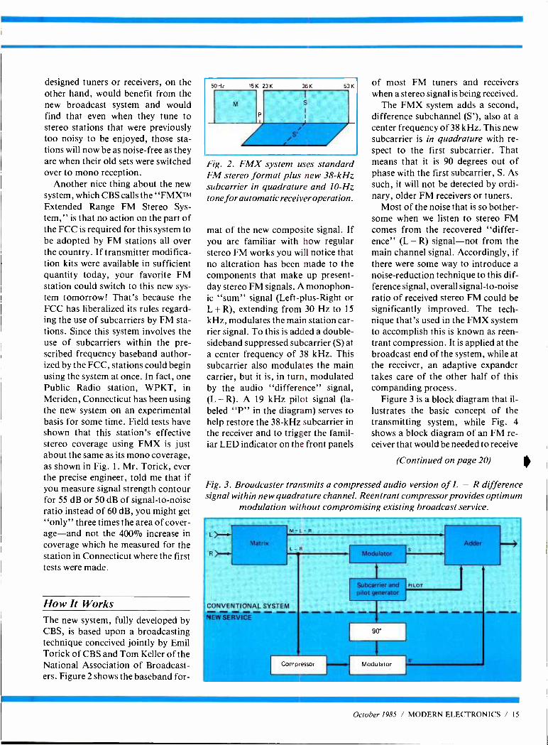
How It Works The new system, fully developed by CBS, is based upon a broadcasting technique conceived jointly by Emil Torick of CBS and Tom Keller of the National Association of Broadcast- ers. Figure 2 shows the baseband for-
50Hi 15K 23K 36 K 53K
Fig. 2. FMX system uses standard FM stereo format plus new 38 -kHz subcarrier in quadrature and 10 -Hz tone for automatic receiver operation.
mat of the new composite signal. If you are familiar with how regular stereo FM works you will notice that no alteration has been made to the components that make up present - day stereo FM signals. A monophon- ic "sum" signal (Left -plus -Right or L + R), extending from 30 Hz to 15
kHz, modulates the main station car- rier signal. To this is added a double - sideband suppressed subcarrier (S) at a center frequency of 38 kHz. This subcarrier also modulates the main carrier, but it is, in turn, modulated by the audio "difference" signal, (L - R). A 19 kHz pilot signal (la- beled "P" in the diagram) serves to help restore the 38 -kHz subcarrier in the receiver and to trigger the famil- iar LED indicator on the front panels
of most FM tuners and receivers when a stereo signal is being received.
The FMX system adds a second, difference subchannel (S'), also at a center frequency of 38 kHz. This new subcarrier is in quadrature with re- spect to the first subcarrier. That means that it is 90 degrees out of phase with the first subcarrier, S. As such, it will not be detected by ordi- nary, older FM receivers or tuners.
Most of the noise that is so bother- some when we listen to stereo FM comes from the recovered "differ- ence" (L - R) signal -not from the main channel signal. Accordingly, if there were some way to introduce a noise- reduction technique to this dif- ference signal, overall signal -to -noise ratio of received stereo FM could be significantly improved. The tech- nique that's used in the FMX system to accomplish this is known as reen- trant compression. It is applied at the broadcast end of the system, while at the receiver, an adaptive expander takes care of the other half of this companding process.
Figure 3 is a block diagram that il- lustrates the basic concept of the transmitting system, while Fig. 4 shows a block diagram of an FM re- ceiver that would be needed to receive
(Continued on page 20)
Fig. 3. Broadcaster transmits a compressed audio version of L -R difference signal within new quadrature channel. Reentrant compressor provides optimum
modulation without compromising existing broadcast service.
L - Matrix
R i- M=L R
L - R
CONVENTIONAL SYSTEM
Modulator
Subcarrier and pilot generator
NEW SERVICE
Cony ,-,sor
PILOT
Adder -4
90
Modulator s
October 1985 / MODERN ELECTRONICS / 15
Satellite Communications
Training from NRI!
Move into commercial satellite communications and home satellite TV with NRI's latest training breakthrough!
Explore Every Aspect of Satellite Trans- mission and Reception As You Assemble, Install, and Train With the Complete TVRO System Included in Your Course
Back in 1964, great excitement surrounded the launching of Syncom 2, the true forerunner of today's satellites. But not even the most hopeful of scientists believed that in less than 25 years, communications satellites would have such a tremendous impact on the professional and per- sonal lives of millions of people around the globe.
Today, thanks to the rapid development of satellite technology, a call to Paris is as clear and as easy to make as a call to your next door neighbor ... executives from multi -national corporations and even small businesses use video conferencing to "meet" without leaving their offices ... simultaneously a billion people witness a single event (a soccer game, an inauguration, a benefit rock concert) ... global weather maps transmitted from satel- lites allow meteorologists to forecast weather trends weeks
in advance ... and scientists now explore and investigate the mysteries of outer space without leaving their labs.
And, not surprisingly, these amazing applications of satellite technology have opened up exciting new opportu- nities for the technician trained to install, maintain, trouble- shoot and repair satellite communications equipment.
Home Satellite TV Is Just at the Start of Its Explosive Future
You've seen them in suburban backyards and alongside country farmhouses. Home satellite TV systems are springing up all across the country.
Already there are over a million TVRO (Television Receive -Only) systems in place in the U.S. alone, and experts predict that by 1990, a remarkable 60% of U.S. homes will have a satellite dish. Contributing to the field's phenomenal growth are the support of the FCC and Congress, steady improvement in product quality, the development of smaller dishes, and a growing consumer enthusiasm for satellite TV.
New Jobs, New Careers for the Trained Technician
Now you can take advantage of the exciting opportunities opening up in
this service- and support- intensive industry. NRI's new break-
through training prepares you to fill the increasing need for technicians to install, adjust, and repair earth station
Iliequipment, such as dishes, antennas, receivers, and
amplifiers. As an NRI- trained technician, you can concentrate
your efforts on consumer -oriented TVRO equipment. Or you can use your NRI training to build a career servicing larger commercial or military equipment used both to transmit and receive voice, data, and video signals. You'll also find opportunities in sales and system consulting, a role some expect to increase tenfold within the next five years on both the corporate and consumer levels.
NRI Brings Satellite Technology Down to Earth
Only NRI has the resources and the skills necessary to transform today's most sophisticated technology into understandable, step -by -step training.
NRI's new course in Satellite Communications gets you in on the ground floor of this booming technology. You are thoroughly trained in the necessary basic electronics, fundamental communications principles, and television transmission and operation.
Using the remarkable NRI Discovery Lab ®, you demon- strate first -hand many important points covered in your lessons. You perform critical tests and measurements with your digital multimeter. And, using your NRI Antenna Applications and Design Lab, you assemble and test various types of antennas and matching sections.
Then you concentrate on both commercial and con- sumer satellite earth station equipment, putting theory to practice as you assemble and install the 5' parabolic dish antenna system included in your course.
At -Home Training the Uniquely Successful NRI Way
It's hands -on train- ing, at home .. .
designed around the latest state -of- the -art electronic equip- ment you work with as part of your training. You start from scratch and "discover by doing" all the way up to the level of a fully qualified profes -- sional. You conduct - key experiments... perform vital tests.:. install your own system ... and you do it at the pace that suits you best.
But, most important to your success, you don't do it alone. Built into your NRI training is the enormous experience of our development specialists and instructors, whose long -proven training skills and personal guidance come to you on a one -to-one basis. They are always available for consultation and help.
Your Home Satellite TV System Brings Theory to Life!
The Wilson TVRO system included in your course comes complete with 5' parabolic dish antenna system, low - noise amplifier (LNA), down converter, receiver, low -loss coaxial cable, and even a permanent polar mount.
By training with an actual TVRO system, you'll come to understand the function and operation of a satellite earth station -knowledge that you can apply to both con- sumer and commercial equipment. And once you have completed your TVRO system, you'll have access to the best television entertainment available -direct from the satellite to your home.
Make Your Move Into the Future Today! Send for Your FREE NRI Catalog
Only NRI can train you at home for an exciting and rewarding career as a satellite communications technician. The knowledge and know -how you gain from your NRI training provide you with the soundest possible foundation for further growth with the industry. But now is the time to act. Return the post -paid card to us today. You will receive your 100 -page catalog free. It's filled with all the details you'll want to know about our training methods and materials and our more than 70 years of successful
innovation in at -home, hands -on career training -the kind of experience that enables NRI to provide the most effective training possible to prepare you for today's, and tomor- row's, high -tech opportun- ities. (If the card is missing, write to us at the address below.)
MOF ELECTRONICS
McGraw -Hill Continuing Education Center 3939 Wisconsin Avenue, NW Washington, DC 20016
We'll give you tomorrow.
October 1985 / MODERN ELECTRONICS / 19
Front end and IF subsection
L R
Stereo decoder IIL RI
Quadrature (IL - RI'
stereo decoder
Dematrix and deemphasis
iOUT
Expander and Norm /FMX switch
Audio out
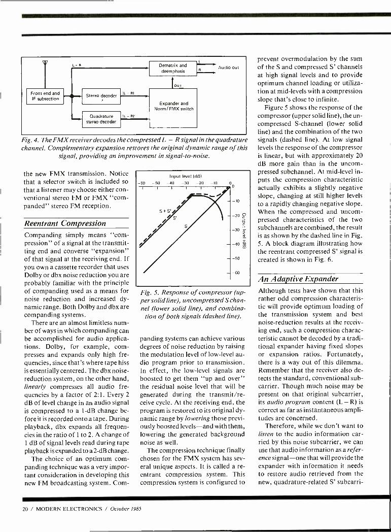
Fig. 4. The FMX receiver decodes the compressed L -R signal in the quadrature channel. Complementary expansion restores the original dynamic range of this
signal, providing an improvement in signal -to- noise.
the new FMX transmission. Notice that a selector switch is included so that a listener may choose either con- ventional stereo FM or FMX "corn- panded" stereo FM reception.
Reentrant Compression Companding simply means "corn - pression" of a signal at the transmit- ting end and converse "expansion" of that signal at the receiving end. If you own a cassette recorder that uses Dolby or dbx noise reduction you are probably familiar with the principle of companding used as a means for noise reduction and increased dy- namic range. Both Dolby and dbx are companding systems.
There are an almost limitless num- ber of ways in which companding can be accomplished for audio applica- tions. Dolby, for example, com- presses and expands only high fre- quencies, since that's where tape hiss is essentially centered. The dbx noise - reduction system, on the other hand, linearly compresses all audio fre- quencies by a factor of 2:1. Every 2
dB of level change in an audio signal is compressed to a 1 -dB change be- fore it is recorded onto a tape. During playback, dbx expands all frequen- cies in the ratio of 1 to 2. A change of 1 dB of signal levels read during tape playback is expanded to a 2-dB change.
The choice of an optimum corn - panding technique was a very impor- tant consideration in developing this new FM broadcasting system. Com-
Fig. 5. Response of compressor (up- per solid line), uncompressed S chan- nel (lower solid line), and combina-
tion of both signals (dashed line).
panding systems can achieve various degrees of noise reduction by raising the modulation level of low -level au- dio program prior to transmission. In effect, the low -level signals are boosted to get them "up and over" the residual noise level that will be generated during the transmit /re- ceive cycle. At the receiving end, the program is restored to its original dy- namic range by lowering those previ- ously boosted levels -and with them, lowering the generated background noise as well.
The compression technique finally chosen for the FMX system has sev- eral unique aspects. It is called a re- entrant compression system. This compression system is configured to
prevent overmodulation by the sum of the S and compressed S' channels at high signal levels and to provide optimum channel loading or utiliza- tion at mid -levels with a compression slope that's close to infinite.
Figure 5 shows the response of the compressor (upper solid line), the un- compressed S- channel (lower solid line) and the combination of the two signals (dashed line). At low signal levels the response of the compressor is linear, but with approximately 20 dB more gain than in the uncom- pressed subchannel. At mid -level in- puts the compression characteristic actually exhibits a slightly negative slope, changing at still higher levels to a rapidly changing negative slope. When the compressed and uncom- pressed characteristics of the two subchannels are combined, the result is as shown by the dashed line in Fig. 5. A block diagram illustrating how the reentrant compressed S' signal is created is shown in Fig. 6.
An Adaptive Expander Although tests have shown that this rather odd compression characteris- tic will provide optimum loading of the transmission system and best noise -reduction results at the receiv- ing end, such a compression charac- teristic cannot be decoded by a tradi- tional expander having fixed slopes or expansion ratios. Fortunately, there is a way out of this dilemma. Remember that the receiver also de- tects the standard, conventional sub - carrier. Though much noise may be present on that original subcarrier, its audio program content (L R) is
correct as far as instantaneous ampli- tudes are concerned.
Therefore, while we don't want to listen to the audio information car- ried by this noise subcarrier, we can use that audio information as a refer- ence signal -one that will provide the expander with information it needs to restore audio retrieved from the new, quadrature- related S' subcarri-
20 / MODERN ELECTRONICS / October 1985
From demodulators
FW rectifiers
Time constant
Variable -gain amplifier
Comparator
FW rectifier
S (NOISE REDUCED)
4
O V ref
CONVENTIONAL
NOISE REDUCED
O V ref
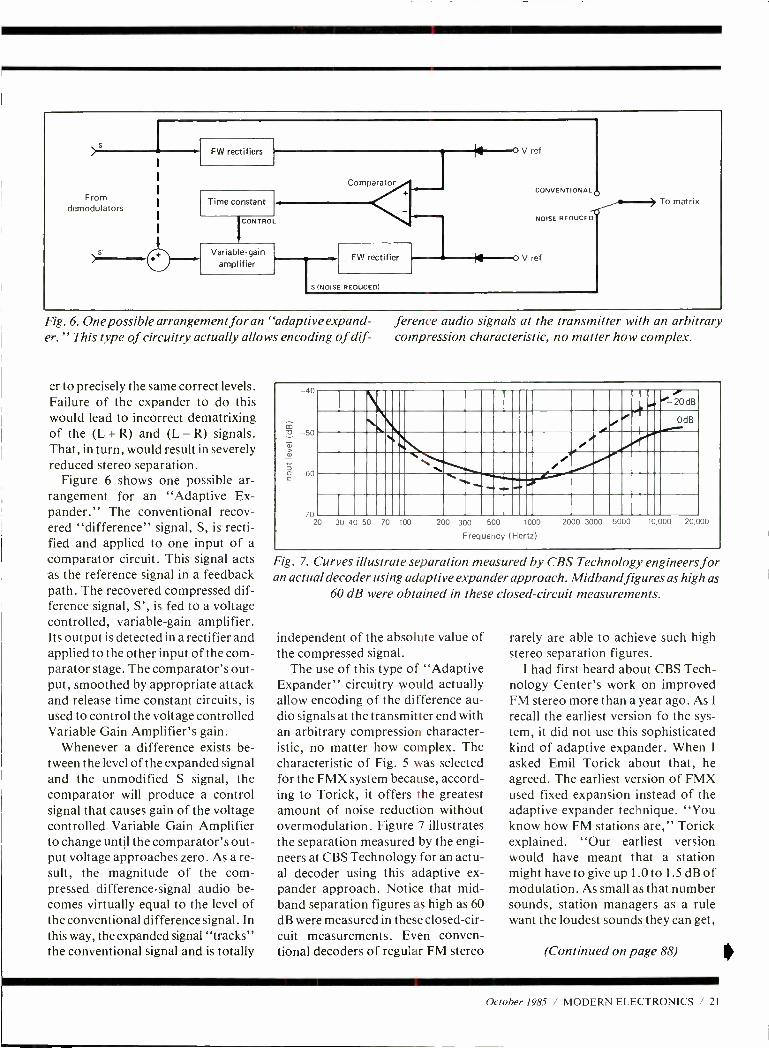
Fig. 6. One possible arrangement for an "adaptive expand- ference audio signals at the transmitter with an arbitrary er." This type of circuitry actually allows encoding of dif- compression characteristic, no matter how complex.
er to precisely the same correct levels. Failure of the expander to do this would lead to incorrect dematrixing of the (L + R) and (L - R) signals. That, in turn, would result in severely reduced stereo separation.
Figure 6 shows one possible ar- rangement for an "Adaptive Ex- pander." The conventional recov- ered "difference" signal, S, is recti- fied and applied to one input of a comparator circuit. This signal acts as the reference signal in a feedback path. The recovered compressed dif- ference signal, S', is fed to a voltage controlled, variable -gain amplifier. Its output is detected in a rectifier and applied to the other input of the com- parator stage. The comparator's out- put, smoothed by appropriate attack and release time constant circuits, is
used to control the voltage controlled Variable Gain Amplifier's gain.
Whenever a difference exists be- tween the level of the expanded signal and the unmodified S signal, the comparator will produce a control signal that causes gain of the voltage controlled Variable Gain Amplifier to change until the comparator's out- put voltage approaches zero. As a re- sult, the magnitude of the com- pressed difference -signal audio be- comes virtually equal to the level of the conventional difference signal. In this way, the expanded signal "tracks" the conventional signal and is totally
á ,
v
-40
-50
60
-70 20
,20dB
I 09
. e OdB
N. N. i i ,
r -... .... ... ....
30 40 50 70 100 200 300 500 1000 2000 3000 5000 10,000 20,000
Frequency (Hertz)
Fig. 7. Curves illustrate separation measured by CBS Technology engineers for an actual decoder using adaptive expander approach. Midband figures as high as
60 dB were obtained in these closed -circuit measurements.
independent of the absolute value of the compressed signal.
The use of this type of "Adaptive Expander" circuitry would actually allow encoding of the difference au- dio signals at the transmitter end with an arbitrary compression character- istic, no matter how complex. The characteristic of Fig. 5 was selected for the FMX system because, accord- ing to Torick, it offers the greatest amount of noise reduction without overmodulation. Figure 7 illustrates the separation measured by the engi- neers at CBS Technology for an actu- al decoder using this adaptive ex- pander approach. Notice that mid - band separation figures as high as 60 dB were measured in these closed -cir- cuit measurements. Even conven- tional decoders of regular FM stereo
rarely are able to achieve such high stereo separation figures.
I had first heard about CBS Tech- nology Center's work on improved FM stereo more than a year ago. As I
recall the earliest version fo the sys- tem, it did not use this sophisticated kind of adaptive expander. When I
asked Emil Torick about that, he agreed. The earliest version of FMX used fixed expansion instead of the adaptive expander technique. "You know how FM stations are," Torick explained. "Our earliest version would have meant that a station might have to give up 1.0 to 1.5 dB of modulation. As small as that number sounds, station managers as a rule want the loudest sounds they can get,
(Continued on page 88)
October 1985 / MODERN ELECTRONICS / 21
lifiIqÌïlÌIÌiPPIÏIÏ0I',1 i1
What can you do Just about
CIE can show you how. Computer technology. Satellite communications. Cable television. Cellular radio. Digital electronics. Robotics. Just a few of the hottest career areas in electronics. The ones everybody is talking about. The ones that are changing the way we live, the way we do business, the way we enter- tain ourselves. The best way to start a career in any of them? By learning the basic electronics theory and principles of how they work from CIE.
Join a leader. Leading the world in specialized electronics train- ing, CIE is the largest school of its kind with over 25,000 students at home and abroad. And with over 50 years of experience teaching electronics to thousands of men and women through proven
methods of independent study without class- room sessions.
Learn as much as you want, when you want. Whether you're interested in learning new skills or upgrading oid ones, earning a diploma or an A.A.S. degree, CIE can match your needs with courses and programs that let you start where you want, go as far as you want from a basic beginner course all the way to CIE's Associate in Applied Science Degree in Electronics -a comprehensive program that prepares you for advanced electronics careers.
Custom training equipment helps you learn. CIE believes in the importance of learning by
with electronics? anything.
doing. So most of our courses include special- ized training laboratories keyed to specific less- ons for practical experience through teaching experiments. Our CIE Microprocessor, for example, comes fully assembled and ready to use to teach you how a computer CPU works through a series of experiments you perform on your own.
Are you ready? If you're ready to do something now about your future, there's no waiting to enroll with CIE. Get all the information you need to enroll simply by calling us toll -free at 1 -800- 321 -2155 (in Ohio, 1- 800 -362 -2105). Or mail in the handy reply coupon or card to Cleveland Institute of Electronics, 1776 East 17th Street, Cleveland, Ohio 44114. CIRCLE 28 ON FREE INFORMATION CARD
World Headquarters Cleveland Institute of Electronics, Inc. 1776 East 17th Street Cleveland, Ohio 44114
I I Please send me your CIE Off -Campus Studies Catalog, including details about the Associate Degree program.
I understand there is no cost for the catalog and a CIE representative may call, but there is no obligation.
Print Name
Address Apt. No
City State Zip
Age Area Code /Phone No /
Check box for G.I. Bill bulletin on Educational Benefits
LI Veteran H Active Duty
MAIL TODAY! MO -42
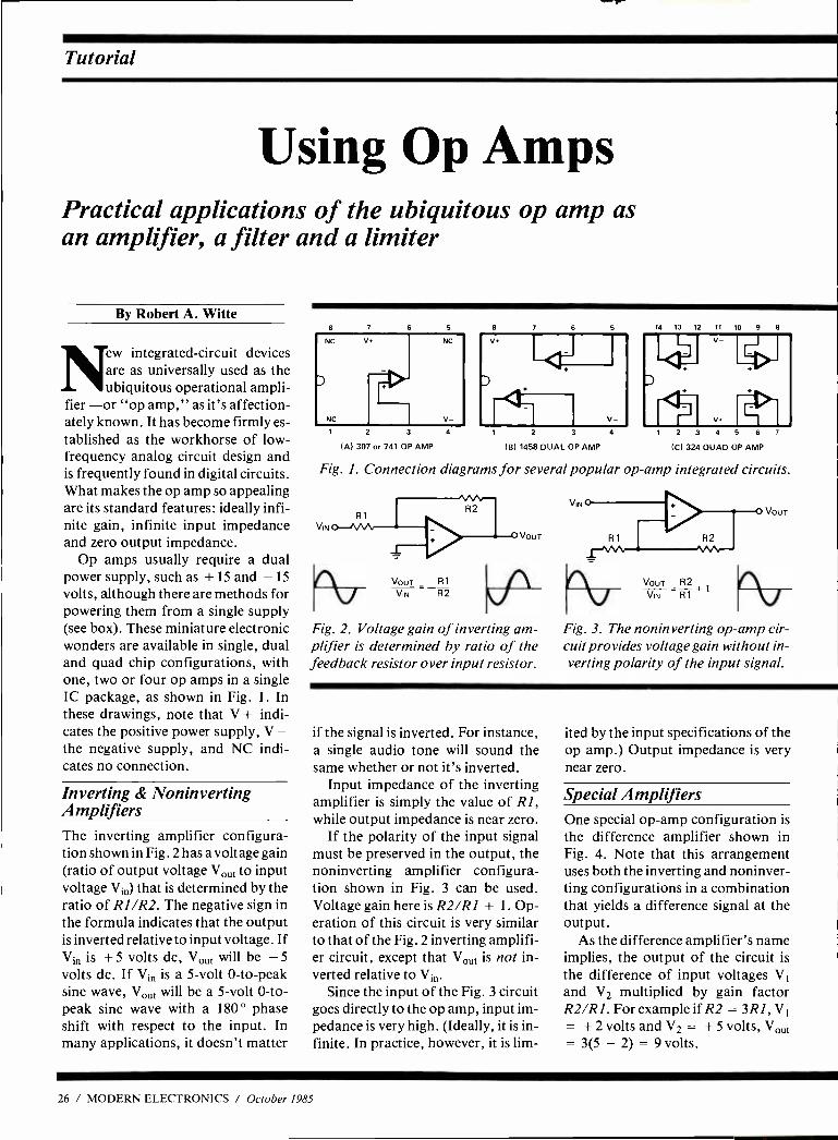
Tutorial
Using Op Amps Practical applications of the ubiquitous op amp as an amplifier, a filter and a limiter
By Robert A. Witte
ew integrated- circuit devices are as universally used as the ubiquitous operational ampli-
fier -or "op amp," as it's affection- ately known. It has become firmly es- tablished as the workhorse of low - frequency analog circuit design and is frequently found in digital circuits. What makes the op amp so appealing are its standard features: ideally infi- nite gain, infinite input impedance and zero output impedance.
Op amps usually require a dual power supply, such as + 15 and 15
volts, although there are methods for powering them from a single supply (see box). These miniature electronic wonders are available in single, dual and quad chip configurations, with one, two or four op amps in a single IC package, as shown in Fig. 1. In these drawings, note that V + indi- cates the positive power supply, V the negative supply, and NC indi- cates no connection.
Inverting & Noninverting Amplifiers The inverting amplifier configura- tion shown in Fig. 2 has a voltage gain (ratio of output voltage Vout to input voltage Vin) that is determined by the ratio of RI /R2. The negative sign in the formula indicates that the output is inverted relative to input voltage. If V1 is + 5 volts dc, Vo t will be 5
volts dc. If Vin is a 5 -volt 0 -to -peak sine wave, Vont will be a 5 -volt 0 -to- peak sine wave with a 180 ° phase shift with respect to the input. In many applications, it doesn't matter
NC V
NC
NC
3 4
(A) 307 or 741 OP AMP (B) 1458 DUAL OP AMP
4
14 13 12 11 10 9
V.
2 3 4 5 6
(C) 324 QUAD OP AMP
7
Fig. I. Connection diagrams for several popular op -amp integrated circuits.
VIN
VouT Ri VIN R2
VOUT
Fig. 2. Voltage gain of inverting am- plifier is determined by ratio of the feedback resistor over input resistor.
VIN
VOUT R2 VIN R1
VOUT
Fig. 3. The noninverting op -amp cir- cuit provides voltage gain without in- verting polarity of the input signal.
if the signal is inverted. For instance, a single audio tone will sound the same whether or not it's inverted.
Input impedance of the inverting amplifier is simply the value of R1, while output impedance is near zero.
If the polarity of the input signal must be preserved in the output, the noninverting amplifier configura- tion shown in Fig. 3 can be used. Voltage gain here is R2 /RI + 1. Op- eration of this circuit is very similar to that of the Fig. 2 inverting amplifi- er circuit, except that Vont is not in- verted relative to Vin.
Since the input of the Fig. 3 circuit goes directly to the op amp, input im- pedance is very high. (Ideally, it is in- finite. In practice, however, it is lim-
ited by the input specifications of the op amp.) Output impedance is very near zero.
Special Amplifiers One special op -amp configuration is the difference amplifier shown in Fig. 4. Note that this arrangement uses both the inverting and noninver- ting configurations in a combination that yields a difference signal at the output.
As the difference amplifier's name implies, the output of the circuit is the difference of input voltages V1
and V2 multiplied by gain factor R2 /R1. For example if R2 = 3R1, V = + 2 volts and V2 = + 5 volts, Vout = 3(5 2) = 9 volts.
26 / MODERN ELECTRONICS / October 1985
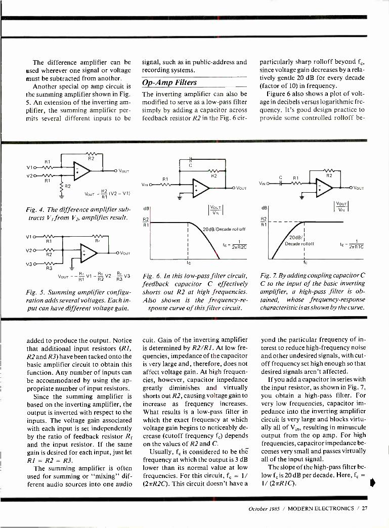
The difference amplifier can be used wherever one signal or voltage must be subtracted from another.
Another special op amp circuit is
the summing amplifier shown in Fig. S. An extension of the inverting am- plifier, the summing amplifier per- mits several different inputs to be
signal, such as in public- address and recording systems.
Op -Amp Filters The inverting amplifier can also be modified to serve as a low -pass filter simply by adding a capacitor across feedback resistor R2 in the Fig. 6 cir-
particularly sharp rolloff beyond fc,
since voltage gain decreases by a rela- tively gentle 20 dB for every decade (factor of 10) in frequency.
Figure 6 also shows a plot of volt- age in decibels versus logarithmic fre- quency. It's good design practice to provide some controlled rolloff be-
V1
V2
Fig. 4. The difference amplifier sub- tracts V1 from V2, amplifies result.
V1 R1
V2 R2
V3 R3
Vc)UT
VouT -RV1-R2V2 R3
5. Summing amplifier configu- ration adds several voltages. Each in- put can have different voltage gain.
VIN
dB
R2 R1
VOUT
VIN
VOUT
20dB/Decade rolloff
c
1
fc 2irR2C
Fig. 6. In this low-pass filter circuit, feedback capacitor C effectively shorts out R2 at high frequencies. Also shown is the frequency -re-
sponse curve of this filter circuit.
dB
R2
R1
VOUT
VIN
20dB/ Decade rolloff
fc
VOUT
1
fc 2aR1C
Fig. Z By adding coupling capacitor C C to the input of the basic inverting amplifier, a high-pass filter is ob- tained, whose frequency- response characteristic is as shown by the curve.
added to produce the output. Notice that additional input resistors (R1, R2 and R3) have been tacked onto the basic amplifier circuit to obtain this function. Any number of inputs can be accommodated by using the ap- propriate number of input resistors.
Since the summing amplifier is
based on the inverting amplifier, the output is inverted with respect to the inputs. The voltage gain associated with each input is set independently by the ratio of feedback resistor Rf and the input resistor. If the same gain is desired for each input, just let RI = R2 = R3.
The summing amplifier is often used for summing or "mixing" dif- ferent audio sources into one audio
cuit. Gain of the inverting amplifier is determined by R2 /R1. At low fre- quencies, impedance of the capacitor is very large and, therefore, does not affect voltage gain. At high frequen- cies, however, capacitor impedance greatly diminishes and virtually shorts out R2, causing voltage gain to increase as frequency increases. What results is a low -pass filter in which the exact frequency at which voltage gain begins to noticeably de- crease (cutoff frequency fc) depends on the values of R2 and C.
Usually, fc is considered to be th-e frequency at which the output is 3 dB lower than its normal value at low frequencies. For this circuit, fc = 1/ (2irR2C). This circuit doesn't have a
yond the particular frequency of in- terest to reduce high- frequency noise and other undesired signals, with cut- off frequency set high enough so that desired signals aren't affected.
If you add a capacitor in series with the input resistor, as shown in Fig. 7, you obtain a high -pass filter. For very low frequencies, capacitor im- pedance into the inverting amplifier circuit is very large and blocks virtu- ally all of Vi,,, resulting in minuscule output from the op amp. For high frequencies, capacitor impedance be- comes very small and passes virtually all of the input signal.
The slope of the high -pass filter be- low fc is 20 dB per decade. Here, fc = 1/ (271-R /C).
October 1985 / MODERN ELECTRONICS / 27
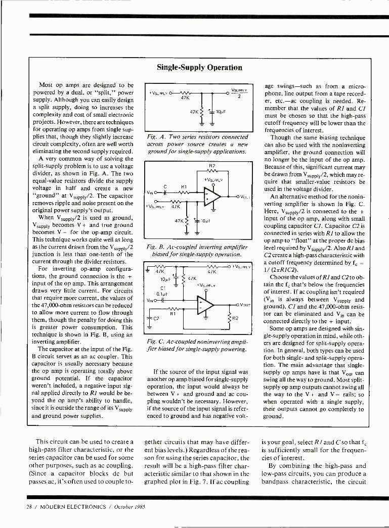
Most op amps are designed to be powered by a dual, or "split," power supply. Although you can easily design a split supply, doing so increases the complexity and cost of small electronic projects. However, there are techniques for operating op amps from single sup- plies that, though they slightly increase circuit complexity, often are well worth eliminating the second supply required.
A very common way of solving the split -supply problem is to use a voltage divider, as shown in Fig. A. The two equal -value resistors divide the supply voltage in half and create a new "ground" at Vsupply /2. The capacitor removes ripple and noise present on the original power supply's output.
When Vsuppiy /2 is used as ground, Vsupply becomes V + and true ground becomes V - for the op -amp circuit. This technique works quite well as long as the current drawn from the Vsupply /2 junction is less than one -tenth of the current through the divider resistors.
For inverting op -amp configura- tions, the ground connection is the + input of the op amp. This arrangement draws very little current. For circuits that require more current, the values of the 47,000 -ohm resistors can be reduced to allow more current to flow through them, though the penalty for doing this is greater power consumption. This technique is shown in Fig. B, using an inverting amplifier.
The capacitor at the input of the Fig. B circuit serves as an ac coupler. This capacitor is usually necessary because the op amp is operating totally above ground potential. If the capacitor weren't included, a negative input sig- nal applied directly to RI would be be- yond the op amp's ability to handle, since it is outside the range of its Vsuppty and ground power supplies.
Single -Supply Operation
Fig. A. Two series resistors connected across power source creates a new ground for single -supply applications.
Fig. B. Ac- coupled inverting amplifier biased for single -supply operation.
= 47K
10pFT
Cl 1 0.1pF
V
IC2
47K 47K
+VSUPPLV
+VSUPPLV
H2
VOUT
Fig. C. Ac- coupled noninverting ampli- fier biased for single -supply powering.
If the source of the input signal was another op amp biased for single -supply operation, the input would always be between V + and ground and ac cou- pling wouldn't be necessary. However, if the source of the input signal is refer- enced to ground and has negative volt-
age swings -such as from a micro- phone, line output from a tape record- er, etc. -ac coupling is needed. Re- member that the values of RI and CI must be chosen so that the high -pass cutoff frequency will be lower than the frequencies of interest.
Though the same biasing technique can also be used with the noninverting amplifier, the ground connection will no longer be the input of the op amp. Because of this, significant current may be drawn from Vsuppty /2, which may re- quire that smaller -value resistors be used in the voltage divider.
An alternative method for the nonin- verting amplifier is shown in Fig. C. Here, Vsupply /2 is connected to the + input of the op amp, along with small coupling capacitor CI. Capacitor C2 is connected in series with RI to allow the op amp to "float" at the proper dc bias level required by Vsuppiy /2. Also RI and C2 create a high -pass characteristic with a cutoff frequency determined by fc = 1/ (271-RIC2).
Choose the values of RI and C2 to ob- tain the fc that's below the frequencies of interest. If ac coupling isn't required (V1 is always between Vsupply and ground), CI and the 47,000 -ohm resis- tor can be eliminated and Vi can be connected directly to the + input.
Some op amps are designed with sin- gle- supply operation in mind, while oth- ers are designed for split -supply opera- tion. In general, both types can be used for both single- and split -supply opera- tion. The main advantage that single - supply op amps have is that Vout can swing all the way to ground. Most split - supply op amp outputs cannot swing all the way to the V + and V - rails; so when operated with a single supply, their outputs cannot go completely to ground.
This circuit can be used to create a high -pass filter characteristic, or the series capacitor can be used for some other purposes, such as ac coupling. (Since a capacitor blocks dc but passes ac, it's often used to couple to-
gether circuits that may have differ- ent bias levels.) Regardless of the rea- son for using the series capacitor, the result will be a high -pass filter char- acteristic similar to that shown in the graphed plot in Fig. 7. If ac coupling
is your goal, select R I and C so that fc
is sufficiently small for the frequen- cies of interest.
By combining the high -pass and low -pass circuits, you can produce a bandpass characteristic, the circuit
28 / MODERN ELECTRONICS / October 1985
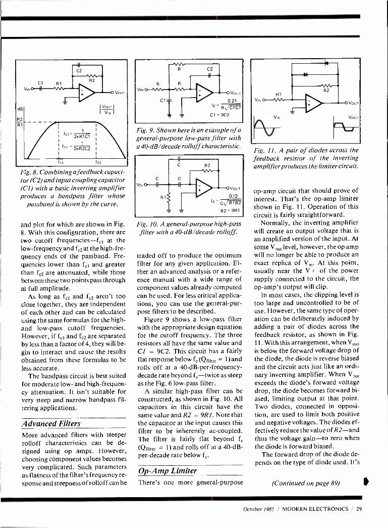
dB
R2 R1
Cl
\,n U-1 R1
C2
1011
fci f C2
Fig. 8. Combining a feedback capaci- tor (C2) and input coupling capacitor (C1) with a basic inverting amplifier produces a bandpass filter whose
passband is shown by the curve.
and plot for which are shown in Fig. 8. With this configuration, there are two cutoff frequencies -fc1 at the low- frequency and fc2 at the high -fre- quency ends of the passband. Fre- quencies lower than fc1 and greater than fc2 are attenuated, while those between these two points pass through at full amplitude.
As long as fef and fc2 aren't too close together, they are independent of each other and can be calculated using the same formulas for the high - and low -pass cutoff frequencies. However, if f, and fc2 are separated by less than a factor of 4, they will be- gin to interact and cause the results obtained from these formulas to be Tess accurate.
The bandpass circuit is best suited for moderate low- and high- frequen- cy attenuation. It isn't suitable for very steep and narrow bandpass fil- tering applications.
Advanced Filters More advanced filters with steeper rolloff characteristics can be de- signed using op amps. However, choosing component values becomes very complicated. Such parameters as flatness of the filter's frequency re- sponse and steepness of rolloff can be
R R
Cl
C2
VouT
0.21 lc
R C1C2
Cl = 9C2
Fig. 9. Shown here is an example of a general - purpose low -pass filter with a 40 -dB /decade rolloff characteristic.
V.
R2
VouT
0.13
fc C R1R2
R2 = 9R1
Fig. 10. A general- purpose high -pass filter with a 40 -dB /decade rolloff.
traded off to produce the optimum filter for any given application. Ei- ther an advanced analysis or a refer- ence manual with a wide range of component values already computed can be used. For less critical applica- tions, you can use the general -pur- pose filters to be described.
Figure 9 shows a low -pass filter with the appropriate design equation for the cutoff frequency. The three resistors all have the same value and Cl = 9C2. This circuit has a fairly flat response below fc (Qf111er = 1) and rolls off at a 40-dB- per -frequency- decade rate beyond fe-twice as steep as the Fig. 6 low -pass filter.
A similar high -pass filter can be constructed, as shown in Fig. 10. All capacitors in this circuit have the same value and R2 = 9R1. Note that the capacitor at the input causes this filter to be inherently ac- coupled. The filter is fairly flat beyond fc
(Qiilter = 1) and rolls off at a 40 -dB- per- decade rate below fc.
Op -Amp Limiter There's one more general -purpose
Rl VIN
VOUT
VOUT
Fig. 11. A pair of diodes across the feedback resistor of the inverting amplifier produces the limiter circuit.
op -amp circuit that should prove of interest. That's the op -amp limiter shown in Fig. 11. Operation of this circuit is fairly straightforward.
Normally, the inverting amplifier will create an output voltage that is
an amplified version of the input. At some Vo f level, however, the op amp will no longer be able to produce an exact replica of V;,,. At this point, usually near the V + of the power supply connected to the circuit, the op -amp's output will clip.
In most cases, the clipping level is
too large and uncontrolled to be of use. However, the same type of oper- ation can be deliberately induced by adding a pair of diodes across the feedback resistor, as shown in Fig. 11. With this arrangement, when Vout is below the forward voltage drop of the diode, the diode is reverse biased and the circuit acts just like an ordi- nary inverting amplifier. When Vo, exceeds the diode's forward voltage drop, the diode becomes forward bi- ased, limiting output at that point. Two diodes, connected in opposi- tion, are used to limit both positive and negative voltages. The diodes ef- fectively reduce the value of R2 -and thus the voltage gain -to zero when the diode is forward biased.
The forward drop of the diode de- pends on the type of diode used. It's
(Continued on page 89)
October 1985 / MODERN ELECTRONICS / 29
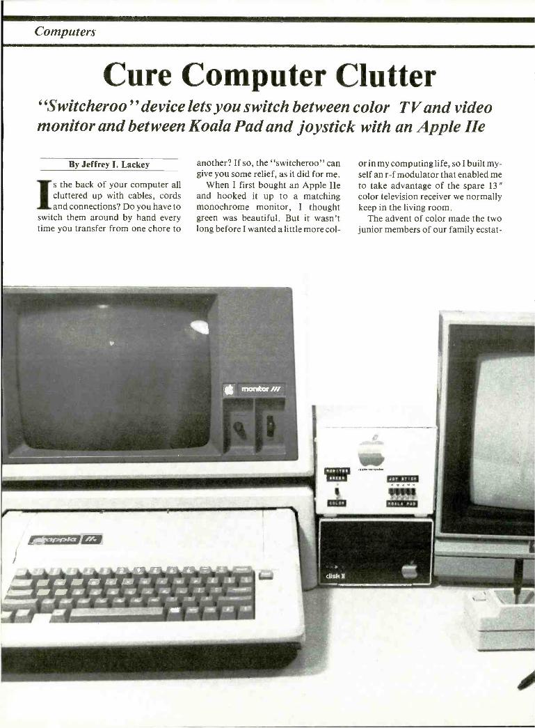
Computers
Cure Computer Clutter "Switcheroo " device lets you switch between color TV and video monitor and between Koala Pad and joystick with an Apple He
By Jeffrey I. Lackey
Is the back of your computer all cluttered up with cables, cords and connections? Do you have to
switch them around by hand every time you transfer from one chore to
another? If so, the "switcheroo" can give you some relief, as it did for me.
When I first bought an Apple IIe and hooked it up to a matching monochrome monitor, I thought green was beautiful. But it wasn't long before I wanted a little more col-
or in my computing life, so I built my- self an r -f modulator that enabled me to take advantage of the spare 13 "
color television receiver we normally keep in the living room.
The advent of color made the two junior members of our family ecstat-
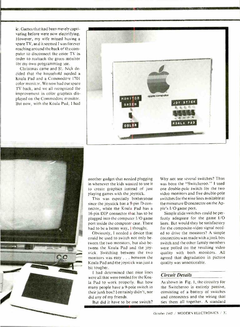
ic. Games that had been merely capti- vating before were now electrifying. However, my wife missed having a spare TV, and it seemed I was forever reaching around the back of the com- puter to disconnect the color TV in order to reattach the green monitor for my own programming use.
Christmas came and St. Nick de- cided that the household needed a Koala Pad and a Commodore 1701
color monitor. We now had our spare TV back, and we all recognized the improvement in color graphics dis- played on the Commodore monitor. But now, with the Koala Pad, I had
MON1TOR
BREEN
another gadget that needed plugging in whenever the kids wanted to use it to create graphics instead of just playing games with the joystick.
This was especially bothersome since the joystick has a 9 -pin D -con- nector, while the Koala Pad has a 16 -pin DIP connector that has to be plugged into the computer I/O game port inside the computer case. There had to be a better way, I thought.
Obviously, I needed a device that could be used to switch not only be- tween the two monitors, but also be- tween the Koala Pad and the joy- stick. Switching between the two monitors was easy ... between the Koala Pad and the joystick was just a bit tougher.
I had determined that nine lines were all that were needed for the Koa- la Pad to work properly. But how many people have a 9 -pole switch in their junk box? I certainly didn't, nor did any of my friends.
But did it have to be one switch?
Why not use several switches? Thus was born the "Switcheroo." I used one double -pole switch for the two video monitors and five double -pole switches for the nine lines available at the miniature D connector on the Ap- ple's I/O game port.
Simple slide switches could be per- fectly adequate for the game I/O lines. But would they be satisfactory for the composite -video signal need- ed to drive the monitors? A simple connection was made with a junk box switch and the other family members were polled on the resulting video quality with both monitors. All agreed that degradation in picture quality was unnoticeable.
Circuit Details
As shown in Fig. 1, the circuitry for the Switcheroo is entirely passive, consisting of a battery of switches and connectors and the wiring that ties them all together. A standard
October 1985 / MODERN ELECTRONICS / 31
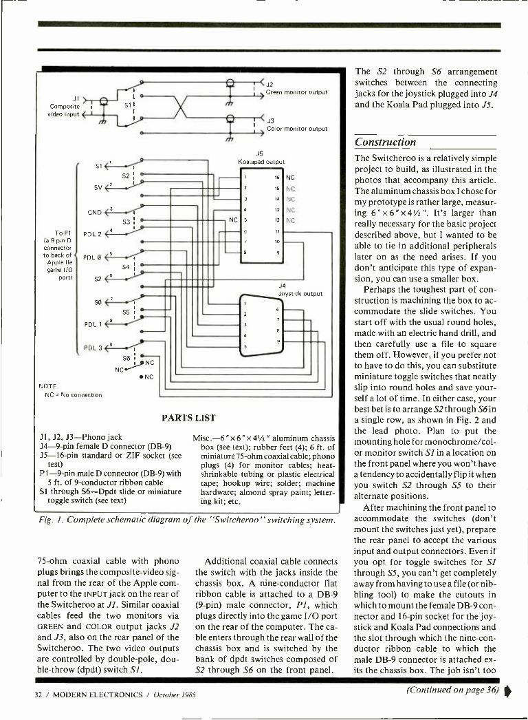
J1
Composite video input
% i
To P1
(a 9 pin D
connector to back of C
Apple Ile game I/O
port)
5V
GND
PDL 2
PDLO
S2
SO
1
l °
<4
S3 ¡ °
1 S4 I
°
B
S5
DL
PDL3<9 °
N
NOTE. NC = No connection.
^.
oNC
J2 Green monitor output
J3 Color monitor output
J5 Koalapad output
1 16 NC
2 15 NC
3 14 NC
4 13 NC
NC 5 12 NC
6 11
7 10
1
2
3
4
5
J4 Joystick output
7
8
PARTS LIST
J1, J2, J3 -Phono jack J4 -9 -pin female D connector (DB -9) J5 -16 -pin standard or ZIF socket (see
test) P1 -9 -pin male D connector (DB -9) with
5 ft. of 9- conductor ribbon cable Si through S6 -Dpdt slide or miniature
toggle switch (see text)
Misc. -6 " x 6 " x 41/2 " aluminum chassis box (see text); rubber feet (4); 6 ft. of miniature 75 -ohm coaxial cable; phono plugs (4) for monitor cables; heat - shrinkable tubing or plastic electrical tape; hookup wire; solder; machine hardware; almond spray paint; letter- ing kit; etc.
Fig. 1. Complete schematic diagram of the "Switcheroo" switching system.
75 -ohm coaxial cable with phono plugs brings the composite -video sig- nal from the rear of the Apple corn - puter to the INPUT jack on the rear of the Switcheroo at J1. Similar coaxial cables feed the two monitors via GREEN and COLOR output jacks J2 and J3, also on the rear panel of the Switcheroo. The two video outputs are controlled by double -pole, dou- ble -throw (dpdt) switch Si.
Additional coaxial cable connects the switch with the jacks inside the chassis box. A nine -conductor flat ribbon cable is attached to a DB -9 (9 -pin) male connector, PI, which plugs directly into the game I/O port on the rear of the computer. The ca- ble enters through the rear wall of the chassis box and is switched by the bank of dpdt switches composed of S2 through S6 on the front panel.
The S2 through S6 arrangement switches between the connecting jacks for the joystick plugged into J4 and the Koala Pad plugged into JS.
Construction The Switcheroo is a relatively simple project to build, as illustrated in the photos that accompany this article. The aluminum chassis box I chose for my prototype is rather large, measur- ing 6 " x 6 " x 4'h ". It's larger than really necessary for the basic project described above, but I wanted to be able to tie in additional peripherals later on as the need arises. If you don't anticipate this type of expan- sion, you can use a smaller box.
Perhaps the toughest part of con- struction is machining the box to ac- commodate the slide switches. You start off with the usual round holes, made with an electric hand drill, and then carefully use a file to square them off. However, if you prefer not to have to do this, you can substitute miniature toggle switches that neatly slip into round holes and save your- self a lot of time. In either case, your best bet is to arrange S2 through S6in a single row, as shown in Fig. 2 and the lead photo. Plan to put the mounting hole for monochrome /col- or monitor switch SI in a location on the front panel where you won't have a tendency to accidentally flip it when you switch S2 through S5 to their alternate positions.
After machining the front panel to accommodate the switches (don't mount the switches just yet), prepare the rear panel to accept the various input and output connectors. Even if you opt for toggle switches for S1 through SS, you can't get completely away from having to use a file (or nib- bling tool) to make the cutouts in which to mount the female DB -9 con- nector and 16 -pin socket for the joy- stick and Koala Pad connections and the slot through which the nine -con- ductor ribbon cable to which the male DB -9 connector is attached ex- its the chassis box. The job isn't too
32 / MODERN ELECTRONICS / October 1985 (Continued on page 36) 0
Professional Books That Help You Get Ahead -And Stay Ahead! PHASE -LOCKED LOOPS by R. G. Best, PHD 050/503 Pub. Pr., $37.50 Club Pr., $28.25
TRANSDUCERS: THEORY AND APPLICATIONS by J. A. Allocca and S. Allen 582997 -5 Pub. Pr., $27.95 Club Pr., $22.95
ELECTRONICS POCKET HANDBOOK by D. L. Metzger 582568 -6 Pub. Pr., $9.95 Club Pr., $6.75
INTEGRATED CIRCUITS APPLICATIONS by A. H. Seidman 582860 -X Pub. Pr., $39.95 Club Pr., $29.95
OPTICAL COMMUNICATION SYSTEMS by J. Gowar 582926 -6 Pub. Pr., $44.95 Club Pr., $32.50
MICROWAVE SEMICONDUCTOR CIRCUIT DESIGN by W. A. Davis 583044 -2 Pub. Pr., $47.50 Club Pr., $35.50
HIGH FREQUENCY SWITCHING POWER SUPPLIES: THEORY AND DESIGN by G. Chryssis 109/494 Pub. Pr., $38.50 Club Pr., $28.75
HANDBOOK OF MICROCOMPUTER BASED INSTRUMENTATION &
CONTROLS by J. D. Lenk 582866 -9 Pub. Pr., $22.95 Club Pr., $18.95
ELECTRONIC COMMUNICATIONS SYSTEMS by W. D. Stanley 582834 -0 Pub. Pr., $25.95 Club Pr., $20.95
MANUAL OF SATELLITE COMMUNICATIONS by E. Fthenakis 225/94X Pub. Pr., $40.95 Club Pr., $30.75
MICROPROCESSOR AND MICROCOMPUTER DATA DIGEST by W. H. Buchsbaum 582835 -9 Pub. Pr., $29.95 Club Pr., $22.50 INTERFACING TO MICROPROCESSORS by J. C. Cluley 114/099 Pub. Pr., $26.50 Club Pr., $19.95
ENCYCLOPEDIA OF COMPUTER SCIENCE AND ENGINEERING by A. Ralston & E. Reilly 582794 -8 Pub Pr., $87.50 Club Pr., $49.95
STANDARD HANDBOOK FOR ELECTRICAL ENGINEERS, 11 /e by D. G. Fink & H. W. Beaty 209/74X Pub. Pr., $79.95 Club Pr., $62.95
ELECTRONICS ENGINEERING FOR PROFESSIONAL ENGINEERS' EXAMS by C. R. Hafer 254/303 Pub. Pr., $32.50 Club Pr., $25.50 MODERN ELECTRONIC CIRCUITS REFERENCE MANUAL by J. Markus 404/461 Pub. Pr., $79.50 Club Pr., $57.95
ANTENNA THEORY: Analysis and Design by C. A. Balanis 582493 -0 Pub. Pr., $41.95 Club Pr., $29.95
ENGINEERING MATHEMATICS HANDBOOK, 2/e by J. J. Tuma 654/298 Pub. Pr., $41.50 Club Pr., $28.95
HANDBOOK OF SEMICONDUCTOR AND BUBBLE MEMORIES by W. A. Triebel & A. E. Chu 582376 -4 Pub. Pr., $24.95 Club Pr., $18.50
' °' ̂ "e ELECTRONICS AND CONTROL ENGINEERS' BOOK CLUB®and..
fl`)) O(frjÍj 1)`)!
800/0 New or Revised From First Edition!
ELECTRONICS ENGINEERS' HANDBOOK, 2/e by D. G. Fink & D. Christiansen 209/812 Pub. Pr., $83.50
Club Pr., $63.95
Keep up with current technology Sharpen your professional skills Be ready for new career opportunities Boost your earning power
New members! Any one of these great professional books for only . . $289 as
Premium with your 1st selection! Values up to $87.50
Why YOU should join now!
ENGINTÉERIÑG
FOR
PflOfESS1ON,AL
EXAMINA
GNARLESpMft
BEST AND NEWEST BOOKS IN YOUR FIELD -Books are selected from a
wide range of publishers by expert editors and consultants to give you continuing access to the best and latest books in your field.
BIG SAVINGS -Build your library and save money too! Savings ranging up
to 35% or more off publishers' list prices- usually 20% to 25%.
BONUS BOOKS -You will immediately begin to participate in our Bonus Book Plan that allows you savings up to 80% off the publishers' prices of many professional and general interest books!
CONVENIENCE -12 -14 times a year (about once every 3 -4 weeks) you receive the Club Bulletin FREE. It fully describes the Main Selection and alternate selections. A dated Reply Card is included. If you want the Main Selection, you simply do nothing -it will be shipped automatically. If you want an alternate selection -or no book at all -you simply indicate it on the Reply Card and return it by the date specified. You will have at least 10 days to decide. If, because of late delivery of the Bulletin you receive a Main Selec- tion you do not want, you may return it for credit at the Club's expense. As a Club member you agree only to the purchase of three books (including your first selection) during your first year of membership. Membership may be discontinued by either you or the Club at any time after you have pur- chased the first selection plus two additional books.
MAIL THIS COUPON TODAY
McGraw -Hill Book Clubs Electronics and Control Engineers' Book Club® PO. Box 582, Hightstown, N. J. 08520
Please enroll me as a member and send me the two books indicated, billing me for the $2.89 premium and my first selection at the Name discounted member's price, plus local tax, shipping and handling charges. I agree to pur- Address /Apt chase a minimum of two additional books dur- ing my first year of membership as outlined City /State /Zip under the Club plan described in this ad. A shipping and handling charge is added to all shipments.
Write Code No. of the Write Code No.
$ 2.89 selection here of First Selection here
Signature _
This order subject to acceptance by McGraw -Hill. All prices subject to change without notice. Offer good only to new members.
E33774
7
i
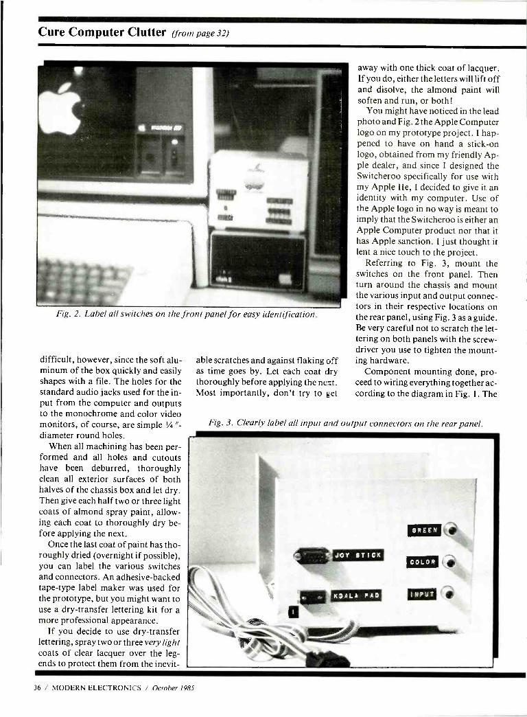
Cure Computer Clutter (from page 32)
Fig. 2. Label all switches on the front panel for easy identification.
difficult, however, since the soft alu- minum of the box quickly and easily shapes with a file. The holes for the standard audio jacks used for the in- put from the computer and outputs to the monochrome and color video monitors, of course, are simple '/ "-
diameter round holes. When all machining has been per-
formed and all holes and cutouts have been deburred, thoroughly clean all exterior surfaces of both halves of the chassis box and let dry. Then give each half two or three light coats of almond spray paint, allow- ing each coat to thoroughly dry be- fore applying the next.
Once the last coat of paint has tho- roughly dried (overnight if possible), you can label the various switches and connectors. An adhesive -backed tape -type label maker was used for the prototype, but you might want to use a dry- transfer lettering kit for a more professional appearance.
If you decide to use dry- transfer lettering, spray two or three very light coats of clear lacquer over the leg- ends to protect them from the inevit-
able scratches and against flaking off as time goes by. Let each coat dry thoroughly before applying the next. Most importantly, don't try to get
away with one thick coat of lacquer. If you do, either the letters will lift off and disolve, the almond paint will soften and run, or both!
You might have noticed in the lead photo and Fig. 2 the Apple Computer logo on my prototype project. I hap- pened to have on hand a stick -on logo, obtained from my friendly Ap- ple dealer, and since I designed the Switcheroo specifically for use with my Apple IIe, I decided to give it an identity with my computer. Use of the Apple logo in no way is meant to imply that the Switcheroo is either an Apple Computer product nor that it has Apple sanction. I just thought it lent a nice touch to the project.
Referring to Fig. 3, mount the switches on the front panel. Then turn around the chassis and mount the various input and output connec- tors in their respective locations on the rear panel, using Fig. 3 as a guide. Be very careful not to scratch the let- tering on both panels with the screw- driver you use to tighten the mount- ing hardware.
Component mounting done, pro- ceed to wiring everything together ac- cording to the diagram in Fig. 1. The
Fig. 3. Clearly label all input and output connectors on the rear panel.
36 / MODERN ELECTRONICS / October 1985
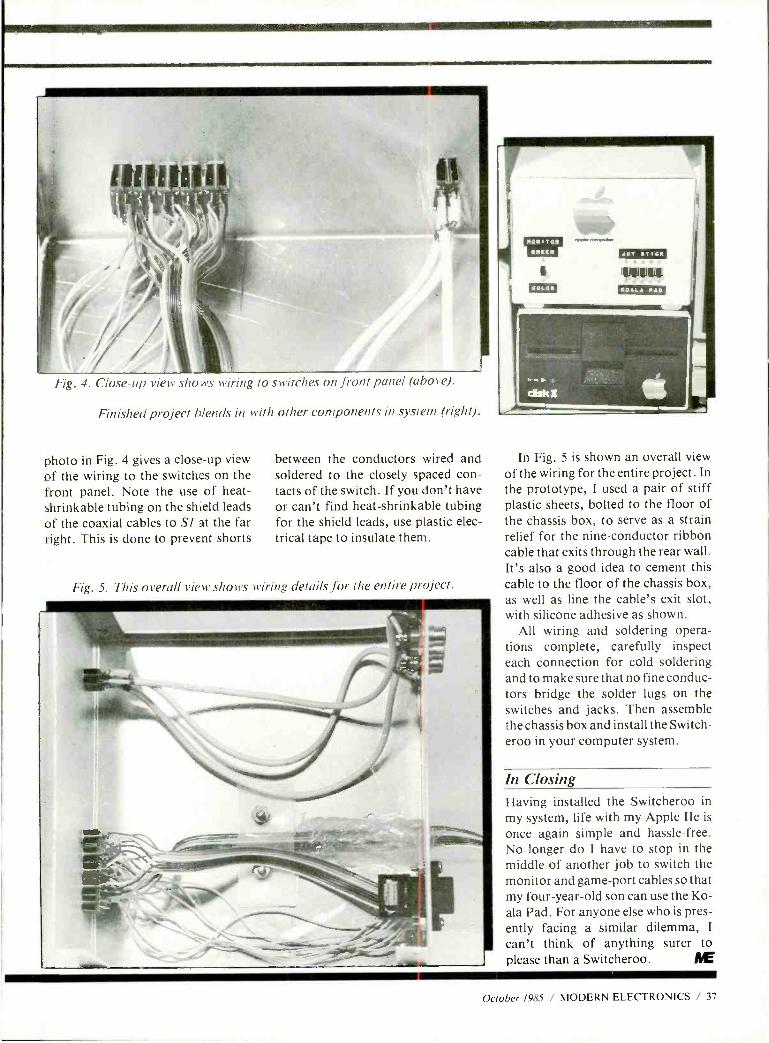
Fig. 4. Close -up view sho.ns wiring to s.witthes on front panel (above).
Finished project blends in with other components in system (right).
photo in Fig. 4 gives a close -up view of the wiring to the switches on the front panel. Note the use of heat - shrinkable tubing on the shield leads of the coaxial cables to Si at the far right. This is done to prevent shorts
between the conductors wired and soldered to the closely spaced con- tacts of the switch. If you don't have or can't find heat -shrinkable tubing for the shield leads, use plastic elec- trical tape to insulate them.
Fig. 5. This overall view shows wiring details for the entire project.
In Fig. 5 is shown an overall view of the wiring for the entire project. In the prototype, I used a pair of stiff plastic sheets, bolted to the floor of the chassis box, to serve as a strain relief for the nine -conductor ribbon cable that exits through the rear wall. It's also a good idea to cement this cable to the floor of the chassis box, as well as line the cable's exit slot, with silicone adhesive as shown.
All wiring and soldering opera- tions complete, carefully inspect each connection for cold soldering and to make sure that no fine conduc- tors bridge the solder lugs on the switches and jacks. Then assemble the chassis box and install the Switch - eroo in your computer system.
In Closing Having installed the Switcheroo in my system, life with my Apple IIe is
once again simple and hassle -free. No longer do I have to stop in the middle of another job to switch the monitor and game -port cables so that my four -year -old son can use the Ko- ala Pad. For anyone else who is pres- ently facing a similar dilemma, I
can't think of anything surer to please than a Switcheroo. AE'
October 1985 / MODERN ELECTRONICS / 37
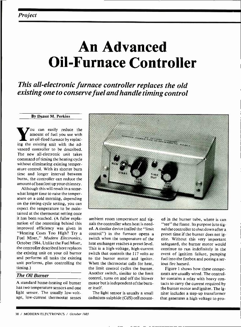
Project
An Advanced Oil -Furnace Controller
This all -electronic furnace controller replaces the old existing one to conserve fuel and handle timing control
By Duane M. Perkins
you can easily reduce the amount of fuel you use with an oil -fired furnace by replac-
ing the existing unit with the ad- vanced controller to be described. The new all- electronic unit takes command of timing the heating cycle without eliminating existing temper- ature control. With its shorter burn time and longer interval between burns, the controller can reduce the amount of heat lost up your chimney.
Although this will result in a some- what longer time to raise the temper- ature on a cold morning, depending on the timing -cycle setting, you can expect the temperature to be main- tained at the thermostat setting once it has been reached. (A fuller expla- nation of the reasoning behind this improved efficiency was given in "Heating Costs Too High? Try a Fuel Miser," Modern Electronics, October 1984. Unlike the Fuel Miser, the controller described here replaces the existing unit on your oil burner and performs all tasks the existing unit performs, plus controlling the timing.)
The Oil Burner A standard home -heating oil burner has two temperature sensors and one light sensor. The usually low -volt- age, low- current thermostat senses
ambient room temperature and sig- nals the controller when heat is need- ed. A similar device (called the "limit control ") in the furnace opens a switch when the temperature of the heat exchanger reaches a preset level. This is a high -voltage, high- current switch that controls the 117 volts ac to the burner motor and igniter. When the thermostat calls for heat, the limit control cycles the burner. Another switch, similar to the limit control, turns on and off the blower motor but is independent of the burn- er itself.
The light sensor is usually a small cadmium -sulphide (CdS) cell mount-
ed in the burner tube, where is can "see" the flame. Its purpose is to sig- nal the controller to shut down after a preset time if the burner does not ig- nite. Without this very important safeguard, the burner motor would continue to run indefinitely in the event of ignition failure, pumping fuel into the firebox and posing a ser- ious fire hazard.
Figure 1 shows how these compo- nents are usually wired. The control- ler contains a relay with heavy con- tacts to carry the current required by the burner motor and igniter. The ig- niter includes a step -up transformer that generates a high voltage to pro-
38 / MODERN ELECTRONICS / October 1985
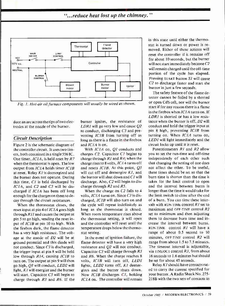
"...reduce heat lost up the chimney."
HOT o
117V a.c.
o NEUTRAL
MAIN SWITCH o LIMIT
CONTROL o Thermostat
Flame detector
BLOWER CONTROL
i
Controller
Blower motor
Burner motor
Igniter
Fig. 1. Hot -air oil furnace components will usually be wired as shown.
duce an arc across the tips of two elec- trodes at the nozzle of the burner.
Circuit Description Figure 2 is the schematic diagram of the controller circuit. It uses two tim- ers, both contained in a single 556 IC. One timer, ICIA, is held reset by R7 when the thermostat is open. The low output from ICIA holds timer ICIB at reset. Relay Kl is deenergized and the burner does not operate. During this time, Cl is held discharged by ICIA, and C2 and C3 will be dis- charged if ICIA has been off long enough for the charges on them to de- cay through the circuit resistances.
When the thermostat closes, the reset input at pin 4 of ICIA goes high through R11 and causes the output at pin 5 to go high, sending the reset in- put of ICIB at pin 10 to high. With the firebox dark, the flame detector has a very high resistance. The volt- age at the anode of D2 will be at ground potential and this diode will not conduct. Since C3 is discharged, the trigger input at pin 8 will be held low through R14, causing ICIB to turn on. The output at pin 9 will then go high, Q3 will conduct, LED2 will light, KI will energize and the burner will start. Capacitor C3 will begin to charge through R3 and R6. If the
burner ignites, the resistance of LDRI will go very low and cause Q2 to conduct, discharging C3 and pre- venting ICIB from turning off as long as there is a flame in the firebox and ICIA is on.
With ICIA on, QI conducts and charges C2. Capacitor Cl begins to charge through RI and R4; when the charge rises to 8 volts, ICIA turns off and resets ICIB. At this point, Q3 will cut off and deenergize KI, and the burner will shut down and CI will discharge. Also, C2 will begin to dis- charge through R2 and R5.
When the charge on C2 falls to 4
volts, ICIA turns on. Since C3 is dis- charged, ICIB will also turn on and the cycle will repeat indefinitely as long as the thermostat is closed. When room temperature rises above the thermostat setting, it will open and the controller will reset until the temperature drops below the thermo- stat setting.
In the event of ignition failure, the flame detector will have a very high resistance and Q2 will not conduct. Capacitor C3 will charge through R3 and R6. When the charge reaches 8
volts, ICIB will turn off, LEDI lights, LED2 turns off, Kl deener- gizes and the burner shuts down. Now IC1B discharges CI, holding IC1A on. The controller will remain
in this state until either the thermo- stat is turned down or power is re- moved. Either of these actions will
reset the controller if it remains off for about 10 seconds, but the burner will not start immediately because C2 will remain charged until the off -time portion of the cycle has elapsed. Pressing START button SI will cause C2 to discharge faster and start the burner in just a few seconds.
The safety feature of the flame de- tector cannot be foiled by a shorted or open CdS cell, nor will the burner start if for any reason there is a flame in the firebox when ICIA turns on. If LDR1 is shorted or has a low resis- tance when the burner is off, D2 will conduct and hold the trigger input at pin 8 high, preventing ICIB from turning on. When ICIA turns on, LEDI will light immediately and the circuit locks up until it is reset.
Potentiometers R1 and R2 allow you to set the run -time and off -time independently of each other such that changing the setting of one does not affect the other. To be useful, these times should be set so that the burn time is shorter than the time it takes for the limit control to open and the interval between burns is
longer than the time it would take for the limit switch to close after the end of a burn. You can time these inter- vals with RUN -TIME control RI set to maximum and OFF -TIME control R2 set to minimum and then adjusting them to decrease burn time and in- crease the interval between burns. RUN -TIME control RI will have a range of about 0.5 second to 10
minutes, OFF -TIME control R2 will range from about 1.5 to 7.5 minutes. The timeout interval is adjustable, via TIMEOUT control R3, from about 16 seconds to 1.6 minutes but should be set for about 45 seconds.
Relay KI should have contacts rat- ed to carry the current specified for your burner. A Radio Shack No. 275 -
218B with the two sets of contacts in
October 1985 / MODERN ELECTRONICS / 39
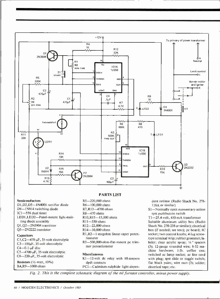
+12V o
R4
1K
Q1
2N3904
S1 O
START R5
220K
R1
1M RUN TIME
14
R12
22K M-
C2
470p F
R2
1M OF F - TIME
Cl 470N F
vu
DISCH
THRESH
TRIG
CONI GND
IC1A 1/2556
RES
OUT
4
5
3 C4
1NF
TF
R11
330
THERMOSTAT
LDR1
R14 10K
R7
4 7K
R3 500K
TIME -OUT
R6 100K
13
R9
1K
:"-IILLED2
10
To primary of power transformer
ON Neutral
Limit control L
Burner motor and igniter
B
Dl 1N4001
R8
470
12
D2 R15 1N914 15K
R13 4.7K
A 02 2N3904
11
Semiconductors D1,D2,D3- 1N4001 rectifier diode D4 -1N914 switching diode IC1 -556 dual timer LEDI,LED2 -Panel -mount light -emit-
ting diode assembly Q1 ,Q2-2N3904 transistor Q3- 2N2222 transistor
Capacitors C1,C2- 470 -µF, 35 -volt electrolytic C3- 100µF, 35 -volt electrolytic C4- 0.1 -µF disc C5- 4700 -µF, 35 -volt electrolytic C6- 220 -14F, 35 -volt electrolytic
Resistors (% -watt, 10 %) R4,R9 -1000 ohms
C3 +
loopFT
RES
DISCH
THRESH
TRIG
CONI
IC1B 1/2556
OUT
= Z LEDI
R10 15K
PARTS LIST
R5- 220,000 ohms R6- 100,000 ohms R7,R13 -4700 ohms R8-470 ohms R10,R15- 15,000 ohms R11 -330 ohms R12- 22,000 ohms R14- 10,000 ohms R1,R2- 1- megohm linear -taper poten-
tiometer R3- 500,000- ohm -flat -mount pc trim-
mer potentiometer
Miscellaneous K1 -12 -volt dc relay with 10- ampere
dpdt contacts PC1 -Cadmium-sulphide light -depen-
03 2N2222
dent resistor (Radio Shack No. 276 - 116A or similar)
SI- Normally open momentary- action spst pushbutton switch
T1- 25.4 -volt, 450 -mA transformer Suitable aluminum utility box (Radio Shack No. 270 -238 or similar); electrical box (if needed; see text); pc board; IC socket; two control knobs; 4 -lug screw - type terminal strip; rubber grommet; la- beler; clear acrylic spray; '/4 " spacers (3); 12 -gauge stranded wire; 6 -32 ma- chine hardware; 1 -lb. coffee can; switched ac lamp socket; ac line cord with plug; spst slide or toggle switch; flat black paint; wire nuts (3); solder; electrical tape; etc.
Fig. 2. This is the complete schematic diagram of the oil furnace controller, minus power supply.
40 / MODERN ELECTRONICS / October 1985
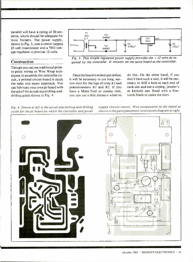
parallel will have a rating of 20 am- peres, which should be adequate for most burners. The power supply, shown in Fig. 3, uses a center -tapped 25 -volt transformer and a 7812 volt- age regulator to provide 12 volts.
Construction Though you can use traditional point - to -point wiring or Wire Wrap tech- niques to assemble the controller cir- cuit, a printed- circuit board is much the safer and easier approach. You can fabricate your own pc board with the aid of the actual -size etching -and- drilling guide shown in Fig. 4.
117V a.c.
T1 25V C T.
N
D3 1N4001
D4 1N4001 ---- _
C5 4700p GND
I
IN IC2 OUT
7812 1 C6
220µF
Fig. 3. This simple regulated power supply provides the + 12 volts dc re-
quired by the controller. It mounts on the same board as the controller.
Once the board is etched and drilled, it will be necessary to cut long, nar- row slots for the lugs of relay KI and potentiometers RI and R2. If you have a Moto -Tool or similar tool, you can use a thin abrasive wheel to
Fig. 4. Shown at left is the actual -size etching- and -drilling guide for the pc board on which the controller and power
do this. On the other hand, if you don't have such a tool, it will be nec- essary to drill a hole at each end of each slot and use a coping, jeweler's or keyhole saw fitted with a fine - tooth blade to make the slots.
supply circuits mount. Wire components to the board as shown in the parts placement /orientation diagram at right.
o o o
om
-01H -- -btl-
o
- 6H
ó
57
+,
i3mvnr
October 1985 / MODERN ELECTRONICS / 41
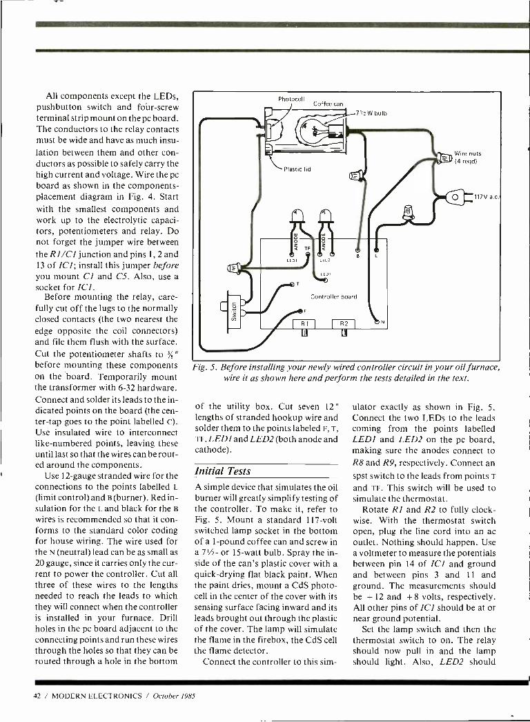
All components except the LEDs, pushbutton switch and foúr -screw terminal strip mount on the pc board. The conductors to the relay contacts must be wide and have as much insu- lation between them and other con- ductors as possible to safely carry the high current and voltage. Wire the pc board as shown in the components - placement diagram in Fig. 4. Start with the smallest components and work up to the electrolytic capaci- tors, potentiometers and relay. Do not forget the jumper wire between the RI /CI junction and pins 1, 2 and 13 of ICI; install this jumper before you mount Cl and C5. Also, use a
socket for ICI. Before mounting the relay, care-
fully cut off the lugs to the normally closed contacts (the two nearest the edge opposite the coil connectors) and file them flush with the surface. Cut the potentiometer shafts to Y8"
before mounting these components on the board. Temporarily mount the transformer with 6 -32 hardware. Connect and solder its leads to the in- dicated points on the board (the cen- ter -tap goes to the point labelled c). Use insulated wire to interconnect like- numbered points, leaving these until last so that the wires can be rout- ed around the components.
Use 12 -gauge stranded wire for the connections to the points labelled L
(limit control) and B (burner). Red in- sulation for the L and black for the B
wires is recommended so that it con- forms to the standard color coding for house wiring. The wire used for the N (neutral) lead can be as small as 20 gauge, since it carries only the cur- rent to power the controller. Cut all three of these wires to the lengths needed to reach the leads to which they will connect when the controller is installed in your furnace. Drill holes in the pc board adjacent to the connecting points and run these wires through the holes so that they can be routed through a hole in the bottom
Fig. 5. Before installing your newly wired controller circuit in your oil furnace, wire it as shown here and perform the tests detailed in the text.
of the utility box. Cut seven 12" lengths of stranded hookup wire and solder them to the points labeled F, T, TF, LEDI and LED2 (both anode and cathode).
Initial Tests
A simple device that simulates the oil burner will greatly simplify testing of the controller. To make it, refer to Fig. 5. Mount a standard 117 -volt switched lamp socket in the bottom of a 1 -pound coffee can and screw in a 7' - or 15 -watt bulb. Spray the in- side of the can's plastic cover with a quick- drying flat black paint. When the paint dries, mount a CdS photo- cell in the center of the cover with its sensing surface facing inward and its leads brought out through the plastic of the cover. The lamp will simulate the flame in the firebox, the CdS cell the flame detector.
Connect the controller to this sim-
ulator exactly as shown in Fig. 5. Connect the two LEDs to the leads coming from the points labelled LED] and LED2 on the pc board, making sure the anodes connect to R8 and R9, respectively. Connect an spst switch to the leads from points T
and TF. This switch will be used to simulate the thermostat.
Rotate RI and R2 to fully clock- wise. With the thermostat switch open, plug the line cord into an ac outlet. Nothing should happen. Use a voltmeter to measure the potentials between pin 14 of ICI and ground and between pins 3 and 11 and ground. The measurements should be + 12 and + 8 volts, respectively. All other pins of ICI should be at or near ground potential.
Set the lamp switch and then the thermostat switch to on. The relay should now pull in and the lamp should light. Also, LED2 should
42 / MODERN ELECTRONICS / October 1985
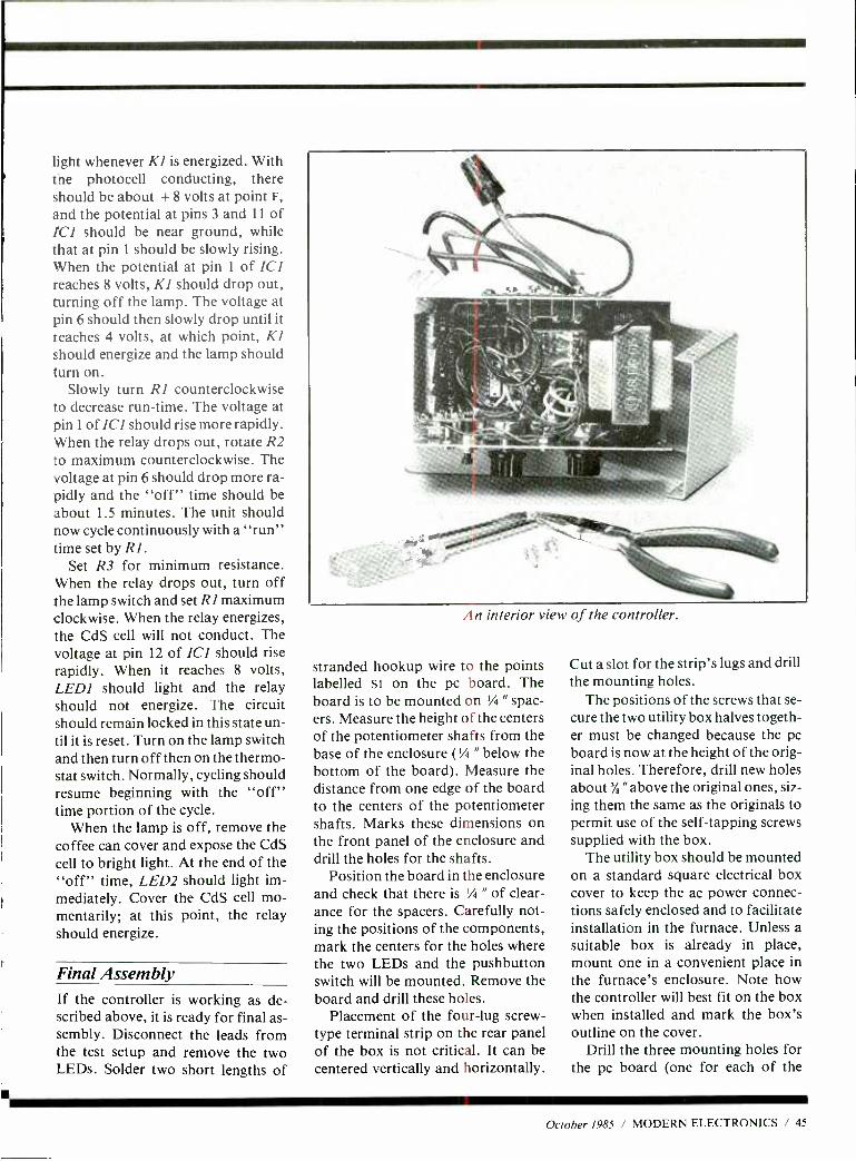
light whenever Kl is energized. With the photocell conducting, there should be about + 8 volts at point F,
and the potential at pins 3 and 11 of ICI should be near ground, while that at pin 1 should be slowly rising. When the potential at pin 1 of ICI reaches 8 volts, Kl should drop out, turning off the lamp. The voltage at pin 6 should then slowly drop until it teaches 4 volts, at which point, KI should energize and the lamp should turn on.
Slowly turn R1 counterclockwise to decrease run -time. The voltage at pin 1 of ICl should rise more rapidly. When the relay drops out, rotate R2 to maximum counterclockwise. The voltage at pin 6 should drop more ra- pidly and the "off" time should be about 1.5 minutes. The unit should now cycle continuously with a "run" time set by Rl.
Set R3 for minimum resistance. When the relay drops out, turn off the lamp switch and set RI maximum clockwise. When the relay energizes, the CdS cell will not conduct. The voltage at pin 12 of ICI should rise rapidly. When it reaches 8 volts, LEDI should light and the relay should not energize. The circuit should remain locked in this state un- til it is reset. Turn on the lamp switch and then turn off then on the thermo- stat switch. Normally, cycling should resume beginning with the "off" time portion of the cycle.
When the lamp is off, remove the coffee can cover and expose the CdS cell to bright light. At the end of the "off" time, LED2 should light im- mediately. Cover the CdS cell mo- mentarily; at this point, the relay should energize.
Final Assembly If the controller is working as de- scribed above, it is ready for final as- sembly. Disconnect the leads from the test setup and remove the two LEDs. Solder two short lengths of
An interior view of the controller.
stranded hookup wire to the points labelled st on the pc board. The board is to be mounted on 1/4 " spac- ers. Measure the height of the centers of the potentiometer shafts from the base of the enclosure (1/4 " below the bottom of the board). Measure the distance from one edge of the board to the centers of the potentiometer shafts. Marks these dimensions on the front panel of the enclosure and drill the holes for the shafts.
Position the board in the enclosure and check that there is 1/4 " of clear- ance for the spacers. Carefully not- ing the positions of the components, mark the centers for the holes where the two LEDs and the pushbutton switch will be mounted. Remove the board and drill these holes.
Placement of the four -lug screw - type terminal strip on the rear panel of the box is not critical. It can be centered vertically and horizontally.
Cut a slot for the strip's lugs and drill the mounting holes.
The positions of the screws that se- cure the two utility box halves togeth- er must be changed because the pc board is now at the height of the orig- inal holes. Therefore, drill new holes about % "above the original ones, siz- ing them the same as the originals to permit use of the self- tapping screws supplied with the box.
The utility box should be mounted on a standard square electrical box cover to keep the ac power connec- tions safely enclosed and to facilitate installation in the furnace. Unless a suitable box is already in place, mount one in a convenient place in the furnace's enclosure. Note how the controller will best fit on the box when installed and mark the box's outline on the cover.
Drill the three mounting holes for the pc board (one for each of the
October 1985 / MODERN ELECTRONICS / 45
transformer's mounting tabs and a third for the left -front hole in the board) through the bottom of the utility box. Set the bottom half of the box on the electrical box's cover, ori- ented properly in the drawn outline (the two mounting holes for the board at the T1 tab locations should overhang the edge of the lid by at least % ") and transfer the electrical box lid's outline to the bottom of the utility box. Mark the front -left board mounting hole outline on the top of the electrical box's lid and drill this hole. Fasten the two pieces together with 6 -32 machine hardware.
Next, drill two more screw holes through both metal pieces for two more sets of machine hardware. Make sure you position these holes where they will not interfere with ei- ther the circuit board assembly or proper mounting of the lid on the electrical box. Secure the two pieces together with 6 -32 x '/ " machine screws, lockwashers and nuts. Flip over the assembly and drill a '/ " hole through the bottom of the utility box, centering it within the large hole area of the electrical box lid. Deburr the newly drilled hole and then line it with a rubber grommet.
Thoroughly clean all exterior sur- faces of the utility box with fine steel wool. Then use a dry- transfer letter- ing kit or plastic tape labeler to iden- tify the controls, indicators and con- nectors. If you use a dry- transfer let- tering kit, spray two or three light coats of clear acrylic over all exterior surfaces of the box, allowing each coat to dry before applying the next.
When the acrylic has thoroughly dried, mount the terminal strip on the rear wall of the box. Feed three 6 -32 x 'h " machine screws up through
the three holes in the bottom of the utility box. Drop a VI " spacer onto each screw.
Place electrical tape over the sur- faces of the utility box adjacent to the section where the board's conductors
carry ac line power. Feed the ac pow- er leads from the board through the rubber grommet and lower the board onto the screws, making sure the shafts of RI and R2 properly seat in their holes in the front panel and that no conductors are caught between the board and spacers. Set TI in place over the protruding screws and an- chor with lockwashers and nuts. An- chor the front -left corner of the board in place with another lock - washer and nut.
Mount LEDI, LED2 and SI on the front panel. Tighten the board- secur- ing hardware and check to make sure that the nut and lockwasher at the left -front corner does not interfere with Cl or CS. Cut all wires on the upper side of the board to the lengths needed to complete the interconnec- tions and, referring back to Fig. 2, connect them to the proper points.
Before you close the utility box, it is a good idea to once again check the project for proper operation. To do this, use the test setup shown in Fig. 5
once again. This time, however, con- nect the photocell and thermostat switch to the terminal strip. This done, repeat the tests detailed above to be certain that all connections have been made correctly.
When the lamp turns off, press START pushbutton SI. In just a few seconds, the lamp should turn on. Adjust RI and R2 for the run and off times you want to initially try when the controller is installed and in con- trol of your furnace. Turn off the lamp switch and adjust R3 for a 45- second time -out. After each trial, use the thermostat switch to reset and then restart with the START switch.
Installation & Operation Before you attempt to install the con- troller in your furnace, make sure all ac power is disabled, preferably at the service box. Use wire nuts to con- nect the 117 -volt ac power leads to ex-
isting wiring. Also, ground the con- troller for safety, using bare 12- or 14 -gauge copper wire to connect to the existing ground lead. If it is neces- sary to extend the connections from the project to the existing wiring, use plastic -insulated three -conductor electrical cable with a ground wire.
Connect the flame -detector and thermostat wires to the contacts on the terminal strip on the rear of the controller and turn the thermostat all the way down. Apply power to the controller. Slowly turn up the ther- mostat until the burner kicks on. If the thermostat momentarily breaks after it makes, the off -time must elapse before the burner will start - or you can press the START button to get things rolling.
The burner should cycle according to the times previously set. Make any adjustments necessary if the control settings were moved during installa- tion. Remove power, disconnect the black burner lead and replace the wire nut on the lead to prevent grounding. Recheck for a 45- second time -out before LED2 turns on; re- adjust if necessary. Reconnect the burner lead and close up the box, us- ing the four self- tapping screws.
In Closing
Experience will tell if the times you set are judicious. If it takes longer than you would like to get the tem- perature up to the thermostat setting on a cold morning, increase the run- time or decrease the off -time. The limit to which you can go with either control is determined by the limit control cycle time. Economy is achieved by having the controller de- termine both portions of the cycle. The best compromise will probably be with a setting that runs the burner only long enough for the blower to start and starts the burner shortly af- ter the blower stops. LE
46 / MODERN ELECTRONICS / October 1985
DUALITY COMPONENTS - NOT MAIL ORDER "SECONDS"
ARIES ZERO INSERTION FORCE SOCKETS - cam actuated. true zero insertion- tin plated solder tail pins - capable of being plugged into dip sockets, including wire wrap.
Stock No.
11055 1105a 11057
058
No of Pins 1.9 10.49 50
24 4 98 54.35 53.90 25 515 4 -50 4.05 40 6 at 5.95 5.35 64 1202 1950 9.45
Ic.KOOLERS- from UNRRACKOñe.ip0oin over 2 watts
gg;°aerAlen'ce,e sl
collected C ooler on -
from top seat bottom le and
ckssioated wonlshake
Stock Morsene No. In IC Once
22225 14 5.29 22229 16 .29
i I I
SCREW MACHINED SOCKET a-- PINS, loose, packaged In bags of I ' 1P
100 Stock No. 11310 is solder tail with gold collet tin shell. Stock No l
11311 is wire wrap with gold collet as gold shell 'Oi
Stock .....
No description t Bag 5 Bap t0 Bps 11310 B4901100
solder till oms S 4.95 s 4.45 53.95 11311 wt,n
Pina 11 95 tors 9.50
WILD ROVER touch switch capsule. Operating Each keyboard pc. motion IS 005 without the use
\r1 ntacts. pad I a levered arm Extremety last on ih
bodies 15. ABS
and oil with low noise Normally open bodies and double shot area 1 15 VAC 1 6 amp -30 mililOhm re Ivor keys Mao rating: _ ,stance - 615 iadus by 60 thick 12 VDC @ 20mA
Contact Res: less than 9Ler O canna 70a.Ì1 Stock No 1 -9 10 8 UP 500 ohms Bounce: less 11291 2 os.5mm Se 95 Se so
1 2098 51 42 51 28 than 1 0 m sec 11292 8 ö 0 4 0 á 1 5 54 . 9 9 5 3 6 0
3 X 4 Elastomeric Keyboards YCYYRr. r. r
SUB CUB I and SUB 6 Digit LSI Counter Modules with LCD Readouts CUB II are high and Associated Stock No. Description Price quality, complete LSI 51070 Complete F nGion $45.00 Counter Modules wan Mounting Assemblies LCD readout. Modules plug in p.c. board (Stock No. 510711. SUB CUB I Complete function evaluation kit (Stock No. 51070) contains'. p. c. board 4.5V battery and variable frequency oscillator to supply train of count pulses Stock No. 51070 has L TEST 100011ons13
ATCH, RESET and l i Iq5]
buttons) PC. board unplugs for breach board work
51071
51072
51073
51074
SUB CUB li 51075
(includes batteries but does not include display counter) Mounting P.C. Board 0111
SUB-CUB I display counter module only SUB -CUB Il display counter module only Panel Bezel Evaluation Kit tor SUB -CUB 11 (does not include SUB -CUB II counter module) DATA SHEET
7.50
18.00
24.00
12.00
25
The Battery Just Wrap' Tool New bauery powered tool wraps ms,daled sore and 025 swam posts without neat for paea
qu ulhng and pre slopping Complete
wilh at and 100 M130 AWG woe Stock No usi ion Price
1l..13340 Bane, l
AMC tool waned
-'13 ant 30 A wire 559.95 13391 Replacement bit 10.35 13342 10011 blue replacement wire 7.54 13343 100 tt white replacement wire 7.54 13344 10011 yellow replacement wan 7.54 13345 100 It red epacemenl wvr 7.54
OK MACHINE AND TOOL IC INSERTION/ EXTRACTION KIT Includes DIP IC eatrac lors an0 Inserters to accommodate all ICs from 19 to 40 pins. Tools that engage conductive surfaces are CMOS sale and include ground ing 1995 s O S O $41.34
MICRO Chans -colorfulev,'a 55 charts eliminate the need to It"
umble through manuals and les Fully decoded- instant 1a Al access¡ ä0 totally comprehensive e gives
pin outs, cycle times, boy notes.etc .. etc Stock No n
v _.. 5595
SINTE
23011 aoaomiOebu 2301a 65021856)1 2301 a 8048 and relatives 5 95 23014 54/1400 TTL Rn.*, 23015 assit Algorithms 5 95
23016 80w6iogral!" from a Sam . 5.95 2301. wore. its _.
SINGLE ROW SOCKETS
Send 51 00 postage and handling for FREE COMPLETE CATALOG which includes coupon for 51.00 OFF purchase.
TI WIRE WRAP SOCKETS Tin plated
or I
contact 3 phosphbronze
wrap 100 Stock 1 -99 -499 500 No No Pins
11301 a 5.40 5.36 5.30 11302 14 .59 .54 .45 11303 18 .64 .58 .48 11304 18 .73 .66 .55 11305 20 .99 .90 .75 11306 22 1.12 1.02 .85 11307 24 1.25 1.14 .95 11308 28 1.52 1.38 1.15 11309 40 2.05 1.86 1.55
OPCOA
ra _vs Strip ut 25 collet sockets /pins-
mount odd-center components easily. Gold plated contacts.
Bots s11,100 break Stock No t -24 25 50 able to any number 10/ 40 S1.70 Si .50 $1.30 of contact position,: wanted í
Strip of 40 pins with single beam sockets Tin plated contacts.
Stock No. 1.99 100 500 1000 10850 51.09 S.90 5.82 5.72
PIN FORMING TOOL puts IC's on their true row to row
fr T1
spacing. One side Is
for. 300 centers, Flip tool ONE TOOL DOES over for devices 8 thru 40 PINS) 600 centers. Put device
n tool and squeeze. Stock No. Price Hand Tool 12 $19s NE W1 ANTI -STATIC MODEL
000 4
TI LOW PROFILE SOCKETS Tin plated copper alloy 688 contact pins with gas tight seal.
100 - N
k
1
2
F n
0 s
5.10 5.09 5.08 25.
.1-93
9
2
rJ
I
11203 11204 11205 11208 11207 11208 11209
16 .16 .15 .14 18 .18 .17 .15 20 .20 .18 .16 22 .22 .20 .18 24 .24 .22 .20 28 .28 .26 .25 4o 40 .37 .33
Single Digit Displays - Common Cathode Stock No. Color 1 100 12082 Red S1.12 S .99 12085 Green 1.84 1.83 12087 yellow 1.92 1.70 12089 Orange 2.08 1.84
Right Angle Socket for Abovr Displays
Stock No. 1 100 11010 51.24 S.99
OPTEL LCD's with pins
Stock No. 47005 Stock No. Descnphon 1 10 47005 3'h dig, 5" 5 5.955 5.50 47006 44g,.5' 5.95 5.50
Stock No 47006 47007 4 dig.. T' 11.90 11.00 B.B:B.B
8 BÌ8 B Stock No. 47007
SOCKET WRAP ID Dip socket -sleet plastic panels with numbered soles mom loca non l
-
Slip onto socket celore rapping to identity pins wire
Also wore on them for location IC part number. function etc
S loublesnoot ng« rig
repair 51.95
THERMOPROBE, Identifies Dead Components - Replaces Volt Meters! Identify dead components which do not emit heat. Just point thermistor probe within 1/16" of board - move over components and see which are Fite
per pack dead. 22300 521 95
C28 8th St., Box 410 CO. Frenchtown, NJ 08825
Scotchlleoa Breadboard Systems Basic kit comes with 24 various Dual Sockets, 40 various Plug Strips, wire and tools Kit can be used with any of the six boards.
Stock No. Descripion 03500 Basic Kit 03511 Basic board. 4.5 x 5.5 03508 Intel S8C-8010 Board. 12 o 6.75 03507 Motorola M -6800 Board. 9.75 o 6 03508 S-100 Board. 10 x 5.3 03509 Z -80 Board. 7 7 x 7 5 03510 Eurocard Board. 63 x 3.9
TOLL 800-526-5960
Price 579.95
19.50 64.95 42.95 36.95 39.95 21.95
We accept V15A. MC. C D. CHECK or M O -INCLUDE SHIPPING CHARGES
FREE In NJ (201) 996 -4093 N; ï .85s o
o ro 5100. -5300 Do
CIRCLE 95 ON FREE INFORMATION CARD
Over 75,000 active amateurs in over 125 countries throughout the world read and enjoy a different kind of ham magazine every month. They read CQ.
It's more than just a magazine. It's an institution.
SUBSCRIBE TODAY! O 3 a
a N
t0
U
o 888 `laó
w,..
a5 . 7 - w u
Co N 4-
o9^\h Ñe tewo,d^(,
50°Ke °, O GO^s
p^9°hl °t ód`s p^
he,g\ msso`^ Ot\oeem°N.V°d
io\d e tho1 p\Met ss to tte ó A °omrn. 10 he\ 9ó óoeetytoé eog M óm h\s h m to Ped 1o`e a^v s,ec°te uo^d s1H ̀ et^9 ó 1°f m°\gs1
és.e p ofN °oh Hp
eG°"o,ofV
vG h
e .h
ó
she
oo\dew
V .
sb oo
°
^ ' .0. (.00 ce ee \
o
h
M° oh\s Ï q, ,,1ght,\^ g9
°
rn
°
tt o e\sv\oVlzyf/ Gh °th
0 / ' / pv-a rog ¡M ,
4'Rove W
Pocket Corn II This is THE transceiver for aspr-
_ nq James or Dick Tracys in our community. Full 2-way transmis- sion and a size that fits secretly into your pocket A great gih for
any child Cat 0-1 101
$1695, PAIR ' 4
Signal Injector One of the handiest de- vices to have in your tool box Check out both audio and f.? circuits (harmo- nics extend to many MHz) simply and easily. Often the quickest method of fault finding (and one of the cheapest!) Self con- tained, with probe and earth clip. Cat x1270
The Dick Smith
A1140 MULTIMETER Almost a complete test bench in one package- no wonder its our best selling multimeterl With 100,000 ohm per volt sensitivity and ranges to cover every test set -up, this outstanding meter is all the hobbyist will ever need! Measures transist- ors Ico and Hfe for both NPN and PN P (also good for diode testing) and has an Inbuilt transistor oscillator for capacitance measurement. Cat 0-1140 s7650
RF Probe
V
Extend the useful range of your multi -
meter way up into the RF range with this neat probe. Frequency response is 150Khz to 30MHz (ref. 500KHz) Comes equipped with I banana plugs for direct multi - meter connection. Ideal for use with most multimeters.
Li dG $ o-495 1138
Pcr you LED
Tacho
P ólec \u
. 5000:,5,^ d
C a7ehms
^os .
6P \
`
f S
'
. 415
5
a
p, s e bV
5AM1 so5 'ot.
acesr ̂ 0( Y
EnyGte
2
g
a t
°
s
'
Z
( J ',
5
o' Eps bAhdnfuc5
ó A9 o
g
e \C5
,e\ePg Bt3
B,
ds'^ e O
9,c u' fi 0.od a ̂\sc5
CeNo
°5 ees u
A 0
<
oòooa ' to
Atg ts a
9, ^ost
h O ̂
o gs°gol,^eÒ s
A 4 \Ds
G
oddews, no,
a
I
GaB
^\Í%at q3
rpmV,Qo Y
de
Ks mC^es
5 o eas
ee
^^VomhgN v°,eos
Eo«o\55tV
55 ys^saS 95
Plot
C mhbCOeod
° z
rg.13t9 q5
^ ed gSu° ,e
90° óoK
o ytGo b s
e '2 p33 0b 8° s`t\s.se. Co'
sod`J°' O e^dge
9 i°^u etc.
Fc P0°oM1poeeo`^'ke/g a6sNe'su99CrA/Jr204/5
Electronics for Model Railways Now railway modellers can achieve a great de- gree of realism on their layouts. Level crossing flashing unit. scale fluo- rescent lamps, street signs. Devices to build. Cat 8 -3633
Qyviy 5330
Don't spend a fortune buying a tachometer - build your own and save! Displays engine speed in an analog form in an illuminated row of LED -s. Instructions included- a great kit! Cat K -3240 *
0144s1995 r - r >;a
'4411111:Ñr:= ... :.: :.. dneY
wove ,an
#tig N Met áe
vF Hove you priced a built up wattmeter lately? Just re- leased
500 4/ mFeaktuit
r is n g e assyhp o
ll re u ilcd
i rc u y .r DIRECTIVITY: Specifications
X35 INSERTION LOSS "4i*4FREQUENCY RE-
. SPONSE: usable over frog, range MWER
Cat K -631AX
PO2
Ov sstgsO'Dbs t^B Asen
t°+°Atea p tegpM,ousg s1Ndt. sa,r ravhedFrO.csca
w Gape il9rese ,°' isbg° sos 'K,a 000 QaOc
w twee!' onólpp som AOá
An Australian written and published book- intend- ed for tech students In electronics/electrical en- gineering fields, but has a mine of information for thy hobbyist too. Covers everything from intro- duction to rectifiers to switch mode supplies. Cat B -3623
e ,rf^° , Mla °,MOrW See
c1 th°sord ,ha 2q5 ZgP
4 GiAnr^, /7 W,
L
20db -0.3db
(narrow 400.520 MHz 100 waits
95 SEE AUG REVIEW
/ 73's
The Laser Experimenter's Handbook A hands -on guide to un- derstanding and applying modern laser and laser technology. Gives all the background and theory needed to build actual working lasers, including actual projects complete with data, plans, and op- erational .w -tes. Cat B-
Cat B -3900 Y Stereo Simulator Wish those old video movies had modern stereo sound? This low cost gadget turns almost any mono signal into amazingly good synthetic stereo!
Cat K -3421 $14"
ORDER TOLL FREE 1 -800 -332 537
Transistor assisted Ignition
Now gives even better performance than be- fore with circuit mods enabling high efficiency Er stability, plus special radial fin design heat- sink and die -cast box to get rid of that unwant- ed heat. Ideal for use in all conventional ignition vehicles (doesn't work real well on diesels! ) Cat Cat K-3301**
etéyS24"
Coiled Test wLeads at
meter lead' It wont MMP
t w h these leads.
rede too, weh
0 0 W é52Ó v
C TEST Clip Leads .
I
ll1
Cal
with ICs orientsomp. IC test yt r0th-
wh mfree W
50
ECONOMY `
Ideal ter the hobbyist! ad This Se 1
helwarkshol you should need for set
y of the 14 or toolbox. Screw in and
yob 1lseethat¡st unVersas tile' G quakt makes d one of
set at once that Cat W -4526 the best m town.
5995
wpAilgise
95.I
Universal Test Lead Set
Cat Q -1440
Beautifully mode. We believe this multimeter must be the best value available in America. President Ike insisted that we find a good quality LCD multi - meter that would sell for less than $3000 We worked at it for 3 months and found one!
SPECIFICATIONS ylf DC Volage - 0- 2.20-000v100 volts / DC
Current - 0- 2-20 volts (RMS) , /TA /mil /_G.
DC Current - 0 -2 -20 -200 mA V Resistance - 0'2K- 20K- 200K -2MEG Ohms 200 hour battery life. Full overload protection and diode check function Low low prceand guaranteed
Porgaiall Ignition
Killer Tie ultimate test lead set for the professional! Superb quality coiled test leads for ease and conven- ience. 18 different adaptor probes and plugs. Multi -way test leads makes it simple to carry out any test you desire. Screw in connector ends make this suitable for any meter. Cat W-
$1 295
Qp1co' dw CAR ALARM et Wie One of the most sophisticated, yet simple alarms
y around. It uses a tnggerng technique which makes it less prone to false alarms -a common problem with many car alarms. yet it will sense a voltage drop anywhere in the electrical system. For example, when a door is opened, or a jumper lead is applied to the starter, etc. It is housed in a virtually waterproof die -cast case to minimise ingress of moisture or fumes, and all connections are made to the terminal stop for ea s ostallation and removal.
,
Ingenious but simplecir- cuit basedon a 555 timer that literally kills your car ignition and then re -sets itself. making the thief think something is wrong with the engine. The theo- ry is he'll then go and pinch someone else's car instead. Cat K -3255 Cat K-3255**
S14q5
A 4
oBB(r kI1te0n9_Y
.N,
a
uÓscw t
k :f1a0wrpro
I
c.
°e
t
cbnotó,
'nU
me9a
Y
hoe e
!
Out 0 t e
ge
e
á y '1Ì
e k , t
vac"
C
v1b
1 e we 9p;
oMbnte r1r
r
0
.hák nqem rÿ 59mow,
g
e Te
nocléSgeg Cot
B-2370
$9a- 1
Y
-
ar
l
w
For lightweight
UHF /2m beams, TV & FM antennas
Why spend S5$ more on a heavy weight rotator when all you're turning is a small beam? Our fully automatic rotator is no slouch! With 50kg vertical loading plus wind load of 0.25 sq meters , it's ready for most TV, FM and '
VHF /UHF antennas. And the great news is it requires only a lightweight 3 core cable (very economical!)
V69
Digital ^ muNbároing, Trainer sequencers, umPlexersers, er>c l}
mSpecs: 1)P registers,
eLirt dP71 e tOrbatf2) POwPOwer jock devices
SW: Wu eight free SPU
buttons; uÌ5á Sw (Or ee (5) ÓC Ó% switches )iLOlc interconnected l OÑe Po V 750rt1,q
indicators; LED buffered logic
LED 80
5/4.95. suit (not
Ìnclu(yOk
clock 9 selection ma P Çomes
ale e3w M supply
°mP I COf 4Li25 1010up$119g5ea $ / training
7 995 Cat D -5003
H /DUTY ROTATOR
With a vertical load of up to 250kg and a wind load of 0.4 square meters. our new high load rotator is ideal for VHF beams, many HF beams and virtually all TV antennas. And best of all, unlike previous rotators. it requires just three con- ductors between the control unit and rotator - save SSS on long cable runs. Supplied complete with mast clamps and control unit, ready to mount on a flat tower plate. Cat D- Cat D -5005
Top value Standard
Panel Meters A high quality range of moving coil meters. with full scale accuracy better than 2 %. Pre -calibrated in 5 popular varieties; easily adapted to suit virtually any requirement with shunts and multipliers.
Dimensions: Mounting: Scale area - 2.3" x 1.2" Hole Required - 1.75" Overall - 21" x 2" Soft holes: 1.5" square
O-50uA 0-5A 0-20A (3500 ohms) (0.03 ohms (0.007 ohms Cat
shunt) shunt) at 0.2020 Cat 0 -2030 Cat 0 -2035
-20- +3VU $ (1.228 V /0dB)
Cat 0-2050 10 up 56.95 ea
0.1 mA 0-20v OC (200 ohms) (1 k ohms/V) Cat 0-2010 Cat 0-2040
ONLY
95
Large Panel Meters I> - -- In two ranges - 1 00uA 8 1 mA
Larger style for larger protects. Size is 4' s 3.25" , scale size 4" x 2"
o-1 mA O-1001iA (200 ohms) (3500 ohm) co 0-2060 Cri a -2070
P 9
UHFd15» LOAD
áÓ1;Tám6OH..r ca o
$15-
Microwave Leakage Detector Microwave ovens ers fantastic - da e mer completely sate? Yours cous be leaking aargerosrsaiatron! Check it out with this handy meter. No hone tes raquirnd a 1(-30C15. / l 1(-30C15.
I $895 v
ELECTRONIGS INCORPORATED IN THE STATE OF CALIFORNIA
ORDER TOLL FREE 1 -800 -332 5373
ENQUIRIES PHONE 12 HOURS A DAY! (415) 368 1066 (60m -ópm Poclllc time)
Quote your Vlso /mostercard e
LAMP LOAD Built ,nlo PL-259 plug - ida. or 21MHresranleso
psnows modulation Rated at SW
Cal D-7024 5295
100W LOAD 1155 ww et Re amateur
nye suds. area aaaro.ts
hcontinuous v° ns of heal. t00W M
Cat D.7010 $2950
Ede* "1.1 t Z 95 motor Get -0.2110 10 uP s3 65 ea
many imported
As used y etc.
casse 1 to 10 with Graduatcheck, mope u
talith In gale.91 ff a
125" x O 4' ais (dent
tine level adlustm meter. mounts
o nie with level, etc.
hole centres 2f xfey,lg, ole
10up$1095e0
Moving Iron Ranger
Rugged and accurate AC /DC metres ideal for power supplies, etc. Oval style meter, size app 2"
o-wide 1
a
oA 2.3" high
(AC a oc) $ 95 Cat 0. 2090 ea. o-40V 10 up $6.95 ea
(ac loci
STORES AT:
BERKELEY: 2474 Shattuck Ave., Ph:(415) 486 0755 REDWOOD CITY: 390 Convention Way, Ph:(415) 368 8844
SAN JOSE: 4980 Stevens Creek Blvd, Ph:(408) 241 2266 STORE HOURS: 10am -6pm EVERYDAY MAIL ORDERS: PO Box 8021, Redwood City, CA 94063 HEAD OFFICE: 390 Convention Way,
Redwood City, CA 94063 n p 5 PLUS SNIPPING
ORDERS 51.00 s' P INSIDE USA 5% OF ORDER TOTAL ` P
CIRCLE J6 ON FREE INFY)RM9TIOA t
CM a-20e0
`N\SNO PNO
1QP
(MIN $1.50) \ ?j EFTS OUTS4DS USA 10% OS ORDER A04, P '3 AO TOTAL (MIN \ r`r`QG
./ Q `N/
OV
0P.N\S txaedde016 'p
P S WHERE THE ELECTRONICS ENTHUSIAST IS #1
PS c O
tQ
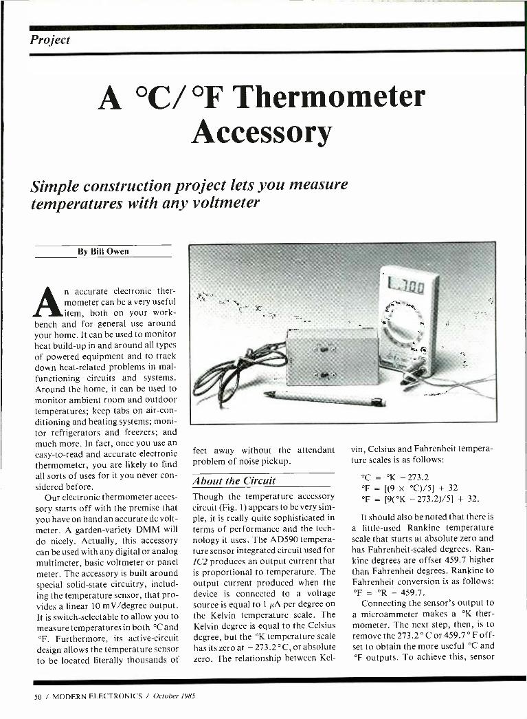
Project
A °C/ °F Thermometer Accessory
Simple construction project lets you measure temperatures with any voltmeter
By Bill Owen
An accurate electronic ther- mometer can be a very useful item, both on your work-
bench and for general use around your home. It can be used to monitor heat build -up in and around all types of powered equipment and to track down heat -related problems in mal- functioning circuits and systems. Around the home, it can be used to monitor ambient room and outdoor temperatures; keep tabs on air -con- ditioning and heating systems; moni- tor refrigerators and freezers; and much more. In fact, once you use an easy -to -read and accurate electronic thermometer, you are likely to find all sorts of uses for it you never con- sidered before.
Our electronic thermometer acces- sory starts off with the premise that you have on hand an accurate dc volt- meter. A garden- variety DMM will
do nicely. Actually, this accessory can be used with any digital or analog multimeter, basic voltmeter or panel meter. The accessory is built around special solid -state circuitry, includ- ing the temperature sensor, that pro- vides a linear 10 mV /degree output. It is switch -selectable to allow you to measure temperatures in both °C and °F. Furthermore, its active -circuit design allows the temperature sensor to be located literally thousands of
feet away without the attendant problem of noise pickup.
About the Circuit Though the temperature accessory circuit (Fig. 1) appears to be very sim- ple, it is really quite sophisticated in terms of performance and the tech- nology it uses. The AD590 tempera- ture sensor integrated circuit used for IC2 produces an output current that is proportional to temperature. The output current produced when the device is connected to a voltage source is equal to 1µA per degree on the Kelvin temperature scale. The Kelvin degree is equal to the Celsius degree, but the °K temperature scale has its zero at - 273.2 ° C, or absolute zero. The relationship between Kel-
vin, Celsius and Fahrenheit tempera- ture scales is as follows:
°C = °K - 273.2 °F = [(9 x °C) /5] + 32
°F = [9( °K - 273.2)/5] + 32.
It should also be noted that there is
a little -used Rankine temperature scale that starts at absolute zero and has Fahrenheit -scaled degrees. Ran- kine degrees are offset 459.7 higher than Fahrenheit degrees. Rankine to Fahrenheit conversion is as follows: °F = °R - 459.7.
Connecting the sensor's output to a microammeter makes a °K ther- mometer. The next step, then, is to remove the 273.2 ° C or 459.7 ° F off- set to obtain the more useful °C and °F outputs. To achieve this, sensor
50 / MODERN ELECTRONICS / October 1985
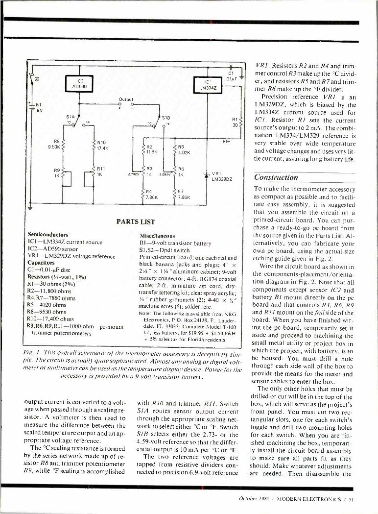
0 \ S2
81
= 9V
R8
9 53K
RB
1K
IC2 AD590
S1A
i R10 17.4K
R11
1K
Output 0 0
IC
LM334Z
2. 32V
S18 'C
.01µF =
R1
30
R2 11.8K
R3
1K 4.59áv
R5 4.02K
R6
1K
R4 R7
7.86K 7.86K
6.9V
4,VR1 LM329DZ
PARTS LIST
Semiconductors IC 1- LM334Z current source IC2 -AD590 sensor VR1- LM329DZ voltage reference Capacitors C1- 0.01 -µF disc Resistors (1/4-watt, 1%) R1 -30 ohms (2 %) R2- 11,800 ohms R4,R7 -7860 ohms R5 -4020 ohms R8 -9530 ohms RI0- 17,400 ohms R3,R6,R9,R11 -1000 -ohm pc -mount
trimmer potentiometers
Miscellaneous B1 -9 -volt transistor battery S1,S2 -Dpdt switch Printed -circuit board; one each red and black banana jacks and plugs; 4" x 21/4 " x 1 % " aluminum cabinet; 9 -volt battery connector; 4 -ft. RG174 coaxial cable; 2 -ft. miniature zip cord; dry - transfer lettering kit; clear spray acrylic; 1/4 " rubber grommets (2); 4-40 x % "
machine scres (6); solder; etc. Note: The following is available from NRG
Electronics, P.O. Box 24138, Ft. Lauder- dale, FL 33037: Complete Model T -100 kit, less battery, for $19.95 + $1.50 P &H + 50/o sales tax for Florida residents.
Fig. 1. This overall schematic of the thermometer accessory is deceptively sim- ple. The circuit is actually quite sophisticated. Almost any analog or digital volt- meter or multimeter can be used as the temperature display device. Power for the
accessory is provided by a 9 -volt transistor battery.
output current is converted to a volt- age when passed through a scaling re- sistor. A voltmeter is then used to measure the difference between the scaled temperature output and an ap- propriate voltage reference.
The °C scaling resistance is formed by the series network made up of re- sistor R8 and trimmer potentiometer R9, while °F scaling is accomplished
with RIO and trimmer R11. Switch SIA routes sensor output current through the appropriate scaling net- work to select either °C or °F. Switch SIB selects either the 2.73- or the 4.59 -volt reference so that the differ- ential output is 10 mA per °C or °F.
The two reference voltages are tapped from resistive dividers con- nected to precision 6.9 -volt reference
VR1. Resistors R2 and R4 and trim- mer control R3 make up the °C divid- er, and resistors R5 and R land trim- mer R6 make up the °F divider.
Precision reference VRI is an LM329DZ, which is biased by the LM334Z current source used for ICI. Resistor RI sets the current source's output to 2 mA. The combi- nation LM334/LM329 reference is very stable over wide temperature and voltage changes and uses very lit- tle current, assuring long battery life.
Construction To make the thermometer accessory as compact as possible and to facili- tate easy assembly, it is suggested that you assemble the circuit on a printed- circuit board. You can pur- chase a ready -to -go pc board from the source given in the Parts List. Al- ternatively, you can fabricate your own pc board, using the actual -size etching guide given in Fig. 2.
Wire the circuit board as shown in the components- placement /orienta- tion diagram in Fig. 2. Note that all components except sensor 1C2 and battery BI mount directly on the pc board and that controls R3, R6, R9 and RII mount on thefoil side of the board. When you have finished wir- ing the pc board, temporarily set it aside and proceed to machining the small metal utility or project box in which the project, with battery, is to be housed. You must drill a hole through each side wall of the box to provide the means for the meter and sensor cables to enter the box.
The only other holes that must be drilled or cut will be in the top of the box, which will serve as the project's front panel. You must cut two rec- tangular slots, one for each switch's toggle and drill two mounting holes for each switch. When you are fin- ished machining the box, temporari- ly install the circuit -board assembly to make sure all parts fit as they should. Make whatever adjustments are needed. Then disassemble the
October 1985 / MODERN ELECTRONICS / 51
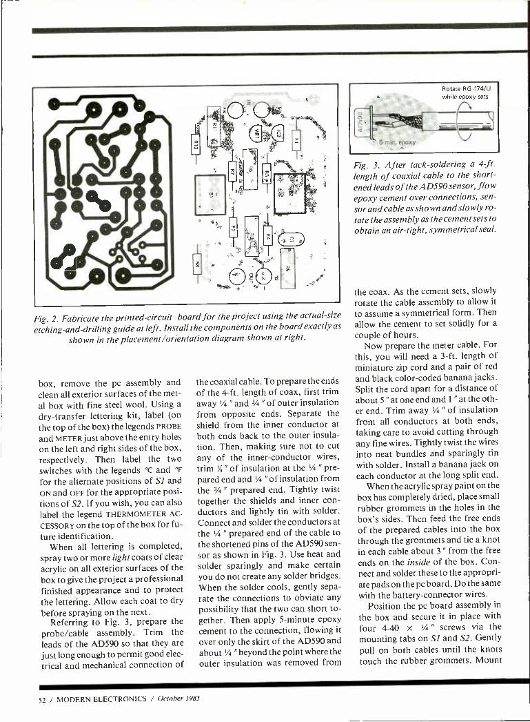
Rotate RG -174/U while epoxy sets
Fig. 2. Fabricate the printed- circuit board for the project using the actual -size
etching- and -drilling guide at left. Install the components on the board exactly as
shown in the placement /orientation diagram shown at right.
box, remove the pc assembly and clean all exterior surfaces of the met- al box with fine steel wool. Using a dry- transfer lettering kit, label (on the top of the box) the legends PROBE
and METER just above the entry holes on the left and right sides of the box, respectively. Then label the two switches with the legends °c and °F
for the alternate positions of SI and ON and OFF for the appropriate posi- tions of S2. If you wish, you can also label the legend THERMOMETER AC-
CESSORY on the top of the box for fu- ture identification.
When all lettering is completed, spray two or more light coats of clear acrylic on all exterior surfaces of the box to give the project a professional finished appearance and to protect the lettering. Allow each coat to dry before spraying on the next.
Referring to Fig. 3, prepare the probe /cable assembly. Trim the leads of the AD590 so that they are just long enough to permit good elec-
trical and mechanical connection of
the coaxial cable. To prepare the ends of the 4 -ft. length of coax, first trim away 1/4 " and 3/4 " of outer insulation from opposite ends. Separate the shield from the inner conductor at both ends back to the outer insula- tion. Then, making sure not to cut any of the inner- conductor wires, trim '/8" of insulation at the 1/4 " pre- pared end and 1/4 " of insulation from the 3/4 " prepared end. Tightly twist together the shields and inner con- ductors and lightly tin with solder. Connect and solder the conductors at the 1/4 " prepared end of the cable to the shortened pins of the AD590 sen- sor as shown in Fig. 3. Use heat and solder sparingly and make certain you do not create any solder bridges. When the solder cools, gently sepa- rate the connections to obviate any possibility that the two can short to- gether. Then apply 5- minute epoxy cement to the connection, flowing it over only the skirt of the AD590 and about '/4 "beyond the point where the outer insulation was removed from
Fig. 3. After tack -soldering a 4-ft. length of coaxial cable to the short- ened leads of the AD590 sensor, flow epoxy cement over connections, sen- sor and cable as shown and slowly ro- tate the assembly as the cement sets to obtain an air- tight, symmetrical seal.
the coax. As the cement sets, slowly rotate the cable assembly to allow it
to assume a symmetrical form. Then allow the cement to set solidly for a
couple of hours. Now prepare the meter cable. For
this, you will need a 3 -ft. length of miniature zip cord and a pair of red and black color -coded banana jacks. Split the cord apart for a distance of about 5 " at one end and 1 " at the oth- er end. Trim away 1/4 " of insulation from all conductors at both ends, taking care to avoid cutting through any fine wires. Tightly twist the wires into neat bundles and sparingly tin with solder. Install a banana jack on each conductor at the long split end.
When the acrylic spray paint on the box has completely dried, place small rubber grommets in the holes in the box's sides. Then feed the free ends of the prepared cables into the box through the grommets and tie a knot in each cable about 3 " from the free ends on the inside of the box. Con- nect and solder these to the appropri- ate pads on the pc board. Do the same with the battery- connector wires.
Position the pc board assembly in
the box and secure it in place with four 4 -40 x '/4 " screws via the mounting tabs on SI and S2. Gently pull on both cables until the knots touch the rubber grommets. Mount
52 / MODERN ELECTRONICS / October 1985
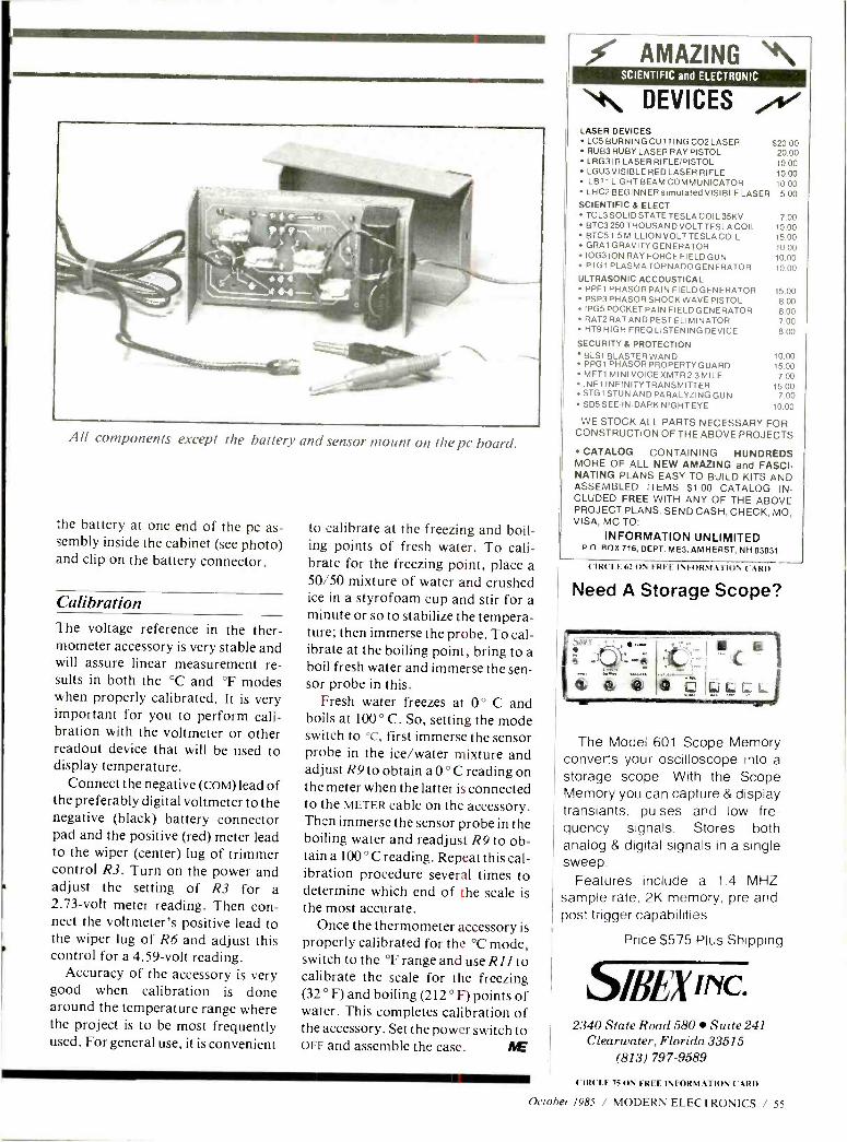
All components except the battery and sensor mount on the pc board.
the battery at one end of the pc as- sembly inside the cabinet (see photo) and clip on the battery connector.
Calibration The voltage reference in the ther- mometer accessory is very stable and will assure linear measurement re- sults in both the °C and °F modes when properly calibrated. It is very important for you to perform cali- bration with the voltmeter or other readout device that will be used to display temperature.
Connect the negative (coM) lead of the preferably digital voltmeter to the negative (black) battery connector pad and the positive (red) meter lead to the wiper (center) lug of trimmer control R3. Turn on the power and adjust the setting of R3 for a 2.73 -volt meter reading. Then con- nect the voltmeter's positive lead to the wiper lug of R6 and adjust this control for a 4.59 -volt reading.
Accuracy of the accessory is very good when calibration is done around the temperature range where the project is to be most frequently used. For general use, it is convenient
to calibrate at the freezing and boil ing points of fresh water. To cali brate for the freezing point, place 50/50 mixture of water and crushe ice in a styrofoam cup and stir for minute or so to stabilize the tempera ture; then immerse the probe. To cal ibrate at the boiling point, bring to boil fresh water and immerse the sen sor probe in this.
Fresh water freezes at 0 ° C and boils at 100 ° C. So, setting the mode switch to °c, first immerse the sensor probe in the ice /water mixture and adjust R9 to obtain a 0 ° C reading on the meter when the latter is connected to the METER cable on the accessory. Then immerse the sensor probe in the boiling water and readjust R9 to ob- tain a 100 ° C reading. Repeat this cal- ibration procedure several times to determine which end of the scale is the most accurate.
Once the thermometer accessory is properly calibrated for the °C mode, switch to the °F range and use R11 to calibrate the scale for the freezing (32 ° F) and boiling (212 ° F) points of water. This completes calibration of the accessory. Set the power switch to OFF and assemble the case. NE
a d a
a
AMAZING "\ SCIENTIFIC and ELECTRONIC *\ DEVICES /
LASER DEVICES LC5 BURNING CUTTING CO2 LASER $20.00 RUB3 RUBY LASER RAY PISTOL 20.00 LRG3IRLASERRIFLE /PISTOL 10.00 LGU3 VISIBLE RED LASER RIFLE 10.00 LBT1 LIGHT BEAM COMMUNICATOR 10.00 LHC2 BEGINNER simulated VISIBLE LASER 5.00
SCIENTIFIC & ELECT TCL3SOLIDSTATETESLACOIL35KV 7.00 BTC3 250 THOUSAND VOLTTESLA COIL 10.00 BTC51.5 MILLION VOLTTESLACOIL 15.00 GRA1 GRAVITY GENERATOR 10.00 IOG3ION RAY FORCE FIELD GUN 10.00 PTG1 PLASMA TORNADO GENERATOR 10.00
ULTRASONIC ACCOUSTICAL PPF1 PHASORPAIN FIELD GENERATOR 15.00 PSP3 PHASOR SHOCK WAVE PISTOL 8.00 IPG5 POCKET PAIN FIELD GENERATOR 8.00 RAT2RATANDPESTELIMINATOR 7.00 HT9 HIGH FREQ LISTENING DEVICE 8.00
SECURITY & PROTECTION BLS1 BLASTER WAND 10.00 PPG1 PHASORPROPERTYGUARD 15.00 MFT1 MINI VOICE XMTR2 -3 MILE 7.00 INF1 INFINITY TRANSMITTER 15.00
STG1 STUN AND PARALYZING GUN 7.00 SD5SEE -IN -DARK NIGHT EYE 10.00
WE STOCK ALL PARTS NECESSARY FOR CONSTRUCTION OF THE ABOVE PROJECTS
CATALOG CONTAINING HUNDREDS MORE OF ALL NEW AMAZING and FASCI- NATING PLANS EASY TO BUILD KITS AND ASSEMBLED ITEMS $1.00 CATALOG IN- CLUDED FREE WITH ANY OF THE ABOVE PROJECT PLANS. SEND CASH, CHECK, MO, VISA, MC TO:
INFORMATION UNLIMITED P O ROX 716, DEPT. ME3, AMHERST, NH 03031
CIRCLE 62 ON FREE INFORMATION ('.ARI)
Need A Storage Scope?
p
The Model 601 Scope Memory converts your oscilloscope into a
storage scope. With the Scope Memory you can capture & display transiants, pulses and low fre- quency signals. Stores both analog & digital signals in a single sweep.
Features include a 1.4 MHZ sample rate, 2K memory, pre and post trigger capabilities.
Price $575 Plus Shipping
S/flEx INC. 2340 State Road 580 Suite 241
Clearwater, Florida 33515 (813) 797 -9589
CIRCLE 75 ON FREE INFORMATION CARD
October 1985 / MODERN ELECTRONICS / 55
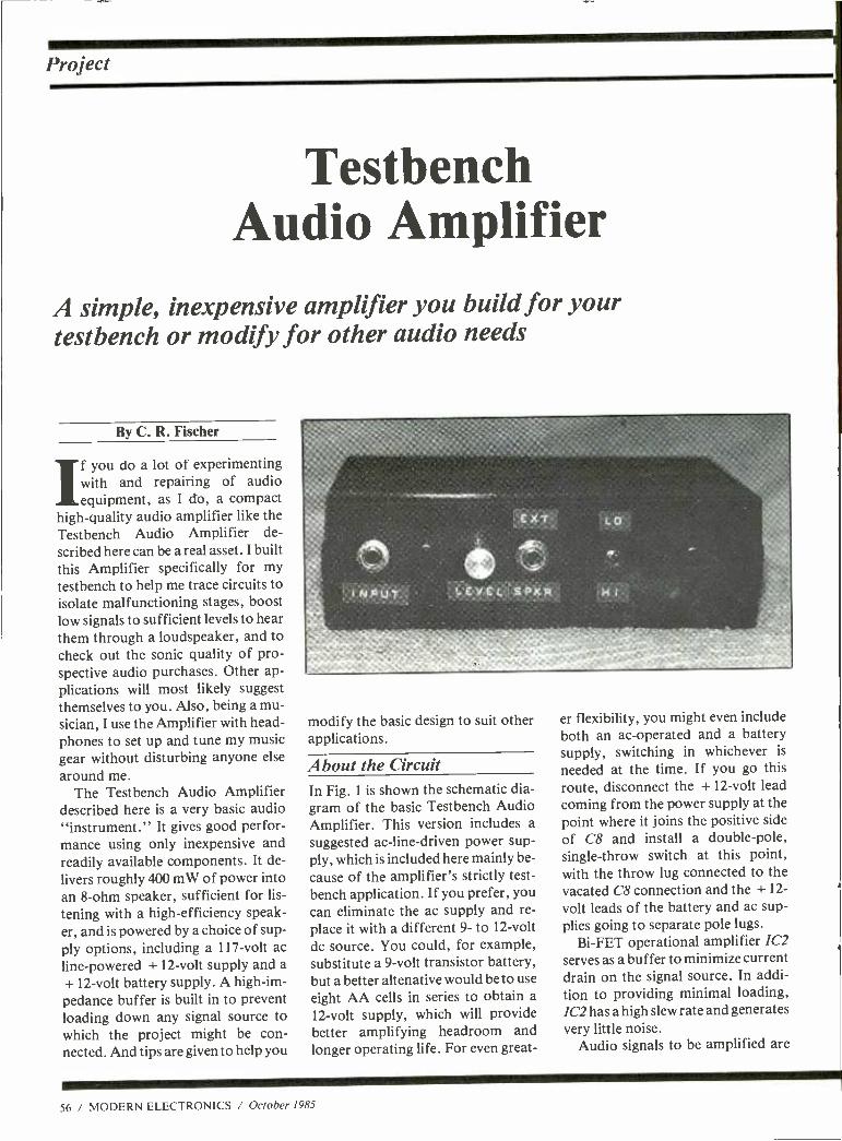
Project
Testbench Audio Amplifier
A simple, inexpensive amplifier you build for your testbench or modify for other audio needs
By C. R. Fischer
If you do a lot of experimenting with and repairing of audio equipment, as I do, a compact
high -quality audio amplifier like the Testbench Audio Amplifier de- scribed here can be a real asset. I built this Amplifier specifically for my
testbench to help me trace circuits to isolate malfunctioning stages, boost low signals to sufficient levels to hear them through a loudspeaker, and to check out the sonic quality of pro- spective audio purchases. Other ap- plications will most likely suggest themselves to you. Also, being a mu- sician, I use the Amplifier with head- phones to set up and tune my music gear without disturbing anyone else
around me. The Testbench Audio Amplifier
described here is a very basic audio "instrument." It gives good perfor- mance using only inexpensive and readily available components. It de-
livers roughly 400 mW of power into an 8 -ohm speaker, sufficient for lis-
tening with a high- efficiency speak- er, and is powered by a choice of sup- ply options, including a 117 -volt ac
line -powered + 12 -volt supply and a
+ 12 -volt battery supply. A high -im-
pedance buffer is built in to prevent loading down any signal source to which the project might be con- nected. And tips are given to help you
modify the basic design to suit other applications.
About the Circuit In Fig. 1 is shown the schematic dia- gram of the basic Testbench Audio Amplifier. This version includes a
suggested ac -line- driven power sup- ply, which is included here mainly be-
cause of the amplifier's strictly test- bench application. If you prefer, you can eliminate the ac supply and re-
place it with a different 9- to 12 -volt
dc source. You could, for example, substitute a 9 -volt transistor battery, but a better altenative would be to use
eight AA cells in series to obtain a
12 -volt supply, which will provide better amplifying headroom and longer operating life. For even great-
er flexibility, you might even include both an ac- operated and a battery supply, switching in whichever is
needed at the time. If you go this route, disconnect the + 12 -volt lead coming from the power supply at the point where it joins the positive side
of C8 and install a double -pole, single -throw switch at this point, with the throw lug connected to the vacated C8 connection and the + 12-
volt leads of the battery and ac sup- plies going to separate pole lugs.
Bi -FET operational amplifier 1C2
serves as a buffer to minimize current drain on the signal source. In addi- tion to providing minimal loading, 1C2 has a high slew rate and generates very little noise.
Audio signals to be amplified are
56 / MODERN ELECTRONICS / October 1985
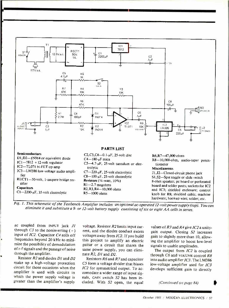
S1
J1 AUDIO INPUT
V
117V.a.c.
Ti
II
12.6V.a.c
+
RECT1 50V. 1A.
_ C1
2200µF
IC1
7812
C5 65 4. F 1K
R7 R4
47K 1011
fib 47K
R1 C4
2.7M ._..
180pF
C3 .1µF
Semiconductors DI,D2 -1N914 or equivalent diode ICI -7812 + 12 -volt regulator IC2 -TL071 bi -FET op amp IC3 -LM386 low -voltage audio ampli-
fier RECT1 -50 -volt, 1- ampere bridge rec-
tifier Capacitors C1- 2200 -8F, 35 -volt electrolytic
R2
1
C2
.1 F
R3
10K
D1
= 1N914
10K D2
= 1N914
IC2 T L071
í,Ú
1 F
IE
R8 10K
VOLUME
PARTS LIST
C2,C3,C6 -0.1 -, F, 25 -volt disc C4- 180-µF mica C5- 4.7 -µF, 25 -volt tantalum or elec-
trolytic C7- 220 -pF, 25 -volt electrolytic C8- 100 -µF, 25 -volt electrolytic Resistors (1/4-watt, 10 %) R1 -2.7 megohms R2 , R3 , R4- 10,000 ohms R5 -1000 ohms
4 220pF
852 SPEAKER
J2 PHONES
R6,R7- 47,000 ohms R8- 10,000 -ohm, audio -taper poten-
tiometer Miscellaneous J1,J2- Closed- circuit phone jack S1,S2 -Spst toggle or slide switch 8 -ohm speaker; pc board or perforated board and solder posts; sockets for IC2 and IC3;. shielded enclosure; control knob for R8; shielded cable; machine hardware; hookup wire; solder; etc.
Fig. 1. This schematic of the Testbench Amplifier includes 'an optional ac- operated 12- voltpo wersupply (top). You cat eliminate it and substitute a 9- or 12 -volt battery supply consisting of six or eight AA cells in series.
ac coupled from INPUT jack JI through C3 to the noninverting ( + ) input of 1C2. Capacitor C4 rolls off
A frequencies beyond 20 kHz to mini- mize the possibility of demodulation of r -f signals and the passage of noise through the amplifier.
Resistor R2 and diodes DI and D2 make up a high -voltage protection circuit for those occasions when the amplifier is used with circuits in which the power supply voltage is greater than the amplifier's supply
voltage. Resistor R2 limits input cur- rent, and the diodes conduct excess voltages away from 1C2. If you build this project to amplify an electric guitar or a circuit that shares the same power supply, you can elimi- nate R2, DI and D2.
Resistors R6 and R7 and capacitor CS form a voltage divider that biases 1C2 for symmetrical output. To ac- comodate a wider range of input sig- nals, GAIN switch S2 has been in- cluded. With S2 open, the equal
values of R3 and R4 give 1C2 a unity - gain output. Closing S2 increases gain to slightly more than 10, allow- ing the amplifier to boost low -level signals to usable amplitudes.
The output from 1C2 is coupled through C6 and VOLUME control R8 into audio amplifier 1C3. The LM386 low -voltage amplifier used for 1C3 develops sufficient gain to directly
(Continued on page 84)
October 1985 / MODERN ELECTRONICS / 57
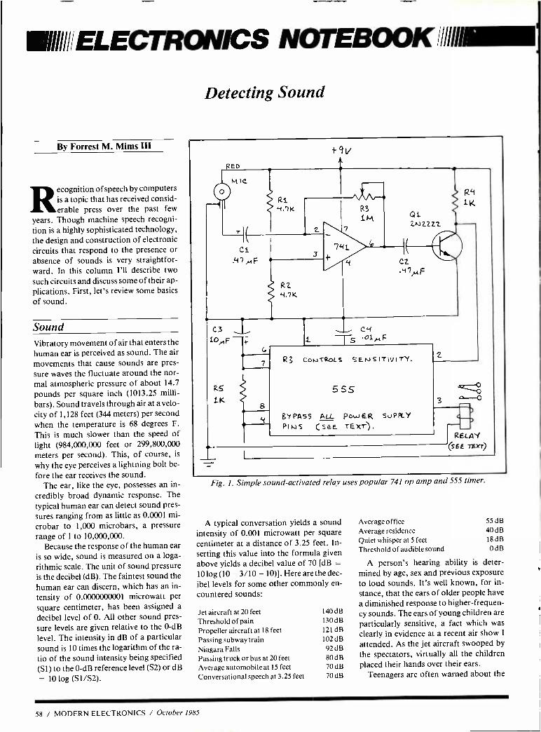
VIII ELECTRONICS NOTEBOOK /11111111EM
By Forrest M. Mims III
Recognition of speech by computers is a topic that has received consid- erable press over the past few
years. Though machine speech recogni- tion is a highly sophisticated technology, the design and construction of electronic circuits that respond to the presence or absence of sounds is very straightfor- ward. In this column I'll describe two
such circuits and discuss some of their ap- plications. First, let's review some basics of sound.
Sound Vibratory movement of air that enters the human ear is perceived as sound. The air
movements that cause sounds are pres- sure waves the fluctuate around the nor- mal atmospheric pressure of about 14.7
pounds per square inch (1013.25 milli-
bars). Sound travels through air at a velo-
city of 1,128 feet (344 meters) per second when the temperature is 68 degrees F.
This is much slower than the speed of light (984,000,000 feet or 299,800,000 meters per second). This, of course, is
why the eye perceives a lightning bolt be-
fore the ear receives the sound. The ear, like the eye, possesses an in-
credibly broad dynamic response. The typical human ear can detect sound pres- sures ranging from as little as 0.0001 mi-
crobar to 1,000 microbars, a pressure range of 1 to 10,000,000.
Because the response of the human ear is so wide, sound is measured on a loga- rithmic scale. The unit of sound pressure is the decibel (dB). The faintest sound the human ear can discern, which has an in-
tensity of 0.0000000001 microwatt per square centimeter, has been assigned a
decibel level of 0. All other sound pres-
sure levels are given relative to the 0 -dB
level. The intensity in dB of a particular sound is 10 times the logarithm of the ra-
tio of the sound intensity being specified (S1) to the 0 -dB reference level (S2) or dB
= 10 log (S1 /S2).
Detecting Sound
FED
+9v
M IC
E
R1
3
R2 4.7K
7,41
y
R3
M Q1 2Nz2zz
CZ .y7).,,F
t C3
iOp, F
R5
1K
C -1
-oi,., F
Rg coLITRoLs SENSITIVITY.
5 SS
g'iPASS ALL Pow ER SUPPLY
PINS (s6E TEXT).
C
7
RELAY (SEE TExr)
Fig. I. Simple sound -activated relay uses popular 741 op amp and 555 timer.
A typical conversation yields a sound intensity of 0.001 microwatt per square centimeter at a distance of 3.25 feet. In- serting this value into the formula given above yields a decibel value of 70 [dB =
10 log (10 -3/10 - 10)]. Herearethedec- ibel levels for some other commonly en- countered sounds:
Jet aircraft at 20 feet Threshold of pain Propeller aircraft at 18 feet Passing subway train Niagara Falls Passing truck or bus at 20 feet Average automobile at 15 feet Conversational speech at 3.25 feet
140 dB 130dB 121 dB 102dB 92 dB 80 dB 70 dB 70 dB
Average office Average residence Quiet whisper at 5 feet Threshold of audible sound
55dB 40dB 18 dB
O dB
A person's hearing ability is deter- mined by age, sex and previous exposure to loud sounds. It's well known, for in- stance, that the ears of older people have a diminished response to higher- frequen- cy sounds. The ears of young children are particularly sensitive, a fact which was
clearly in evidence at a recent air show I
attended. As the jet aircraft swooped by the spectators, virtually all the children placed their hands over their ears.
Teenagers are often warned about the
58 / MODERN ELECTRONICS / October 1985
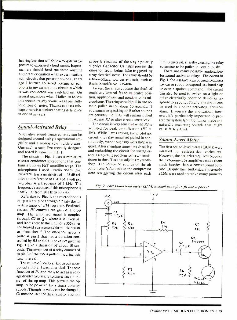
hearing loss that will follow long -term ex- posure to excessively loud music. Experi- menters should heed the same warning and practice caution when experimenting with circuits that generate sounds. Years ago I learned to avoid placing an ear- phone in my ear until the circuit to which is was connected was switched on. On several occasions when I failed to follow this procedure, my reward was a painfully loud tone or noise. Thanks to these mis- haps, there is a distinct hearing deficiency in one of my ears.
Sound - Activated Relay A sensitive sound -triggered relay can be designed around a single operational am- plifier and a monostable multivibrator. One such circuit I've recently designed and tested is shown in Fig. 1.
The circuit in Fig. 1 uses a miniature electret condenser microphone that con- tains a built -in FET amplifier stage. The microphone I used, Radio Shack No. 270 -092B, has a sensitivity of - 65 dB rel- ative to a reference of 0 dB of 1 volt per microbar at a frequency of 1 kHz. The frequency response of this microphone is nearly flat from 20 Hz to 10 kHz.
Referring to Fig. 1, the microphone's output is coupled through Cl into the in- verting input of a 741 op amp. Feedback resistor R3 controls the gain of the op amp. The amplified signal is coupled through C2 to Ql, where it is inverted, and from there to the input of a 555 timer configured as a monostable multivibrator or "one- shot." The one -shot issues a pulse at pin 3 that has a duration con- trolled by R5 and C3. The values given in Fig. 1 give a duration of about 10 sec- onds. The armature of a relay connected to pin 3 of the 555 is pulled in during this time interval.
The values of nearly all the circuit com- ponents in Fig. 1 are noncritical. The sole function of RI and R2 is to act as a volt- age divider to bias the noninverting ( + in- put of the op amp. This permits the op amp to be powered by a single -polarity supply. Though its value can be changed, CI must be used for the circuit to function
properly (because of the single -polarity supply). Capacitor C4 helps prevent the one -shot from being false -triggered by stray electrical noise. The relay should be a low- voltage, low- current unit, such as Radio Shack's No. 275 -004.
To test the circuit, rotate the shaft of sensitivity control R3 to its center posi- tion, apply power, and speak into the mi- crophone. The relay should pull in and re- main pulled in for about 10 seconds. If you continue speaking or if other sounds are present, the relay will remain pulled in. Adjust R3 to alter circuit sensitivity.
The circuit is very sensitive when R3 is adjusted for peak amplification (R3 = 1M). While I was testing the prototype circuit, the relay remained pulled in con- tinuously, even though my workshop was quiet. After spending some time checking and rechecking the circuit for wiring er- rors, I traced the problem to the air condi- tioner in the office that adjoins my work- shop. The combined sounds of the air conditioner's fan, motor and compressor were retriggering the circuit after each
timing interval, thereby causing the relay to appear to be pulled in continuously.
There are many possible applications for sound -activated relays. The circuit in Fig. 1, for instance, can be used to cause a toy car or robot to respond to a hand clap or even a spoken command. The circuit can also be used to switch on a light or other electrically operated device in re- sponse to a sound. Finally, the circuit can be used in a sound -activated intrusion alarm. If you try this application, how- ever, it's particularly important to pro- tect the system from both man-made and naturally occurring sounds that might cause false alarms.
Sound -Level Meter The first sound -level meters (SLMs) were installed in suitcase -size enclosures. However, the batteries required to power their vacuum -tube amplifiers made them much heavier than a conventional suit- case. Despite their bulky size, those early SLMs were used to make many pioneer-
Fig. 2. This sound level meter (SLM) is small enough to fit into a pocket.
October 1985 / MODERN ELECTRONICS / 59
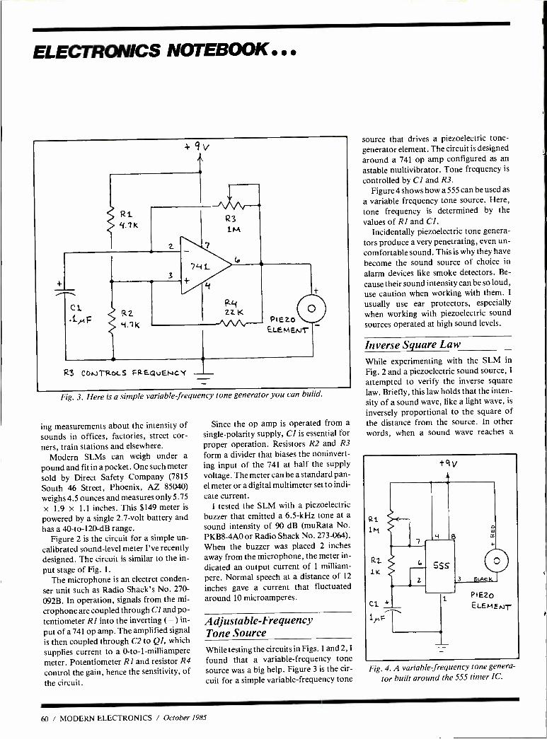
ELECTRONICS NOTEBOOK...
Fig. 3. Here is a simple variable frequency tone generator you can build.
ing measurements about the intensity of sounds in offices, factories, street cor- ners, train stations and elsewhere.
Modern SLMs can weigh under a
pound and fit in a pocket. One such meter sold by Direct Safety Company (7815
South 46 Street, Phoenix, AZ 85040)
weighs 4.5 ounces and measures only 5.75
x 1.9 x 1.1 inches. This $149 meter is
powered by a single 2.7 -volt battery and has a 40 -to- 120 -dB range.
Figure 2 is the circuit for a simple un-
calibrated sound -level meter I've recently designed. The circuit is similar to the in-
put stage of Fig. 1.
The microphone is an electret conden- ser unit such as Radio Shack's No. 270 -
092B. In operation, signals from the mi-
crophone are coupled through Cl and po- tentiometer RI into the inverting ( -) in-
put of a 741 op amp. The amplified signal
is then coupled through C2 to QI, which
supplies current to a 0 -to -l-milliampere meter. Potentiometer RI and resistor R4
control the gain, hence the sensitivity, of the circuit.
Since the op amp is operated from a
single -polarity supply, CI is essential for
proper operation. Resistors R2 and R3
form a divider that biases the noninvert- ing input of the 741 at half the supply voltage. The meter can be a standard pan- el meter or a digital multimeter set to indi-
cate current. I tested the SLM with a piezoelectric
buzzer that emitted a 6.5 -kHz tone at a
sound intensity of 90 dB (muRata No. PKB8 -4A0 or Radio Shack No. 273 -064).
When the buzzer was placed 2 inches
away from the microphone, the meter in-
dicated an output current of 1 milliam-
pere. Normal speech at a distance of 12
inches gave a current that fluctuated around 10 microamperes.
Adjustable- Frequency Tone Source While testing the circuits in Figs. 1 and 2, I
found that a variable- frequency tone source was a big help. Figure 3 is the cir-
cuit for a simple variable- frequency tone
source that drives a piezoelectric tone - generator element. The circuit is designed around a 741 op amp configured as an
astable multivibrator. Tone frequency is
controlled by CI and R3. Figure 4 shows how a 555 can be used as
a variable frequency tone source. Here, tone frequency is determined by the values of RI and Cl.
Incidentally piezoelectric tone genera- tors produce a very penetrating, even un- comfortable sound. This is why they have
become the sound source of choice in
alarm devices like smoke detectors. Be-
cause their sound intensity can be so loud, use caution when working with them. I
usually use ear protectors, especially when working with piezoelectric sound sources operated at high sound levels.
Inverse Square Law While experimenting with the SLM in
Fig. 2 and a piezoelectric sound source, I
attempted to verify the inverse square law. Briefly, this law holds that the inten- sity of a sound wave, like a light wave, is
inversely proportional to the square of the distance from the source. In other words, when a sound wave reaches a
tqv
PIEZO
ELEMENT
Fig. 4. A variable frequency tone genera-
tor built around the 555 timer IC.
60 / MODERN ELECTRONICS / October 1985
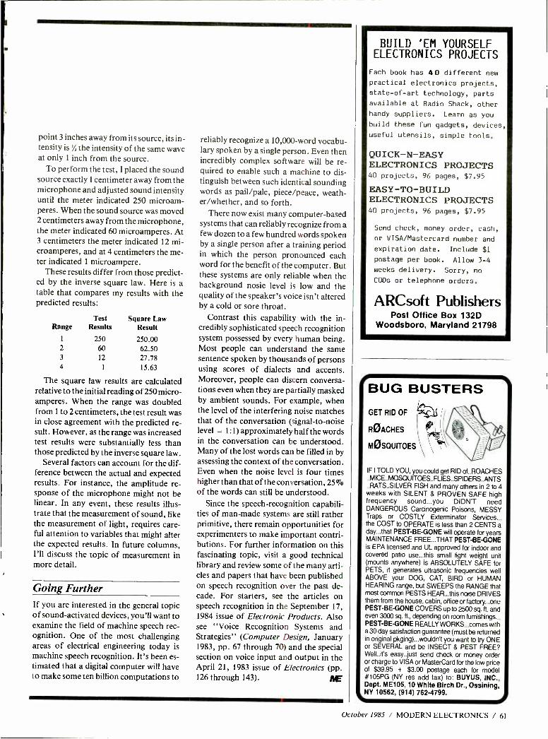
point 3 inches away from its source, its in- tensity is % the intensity of the same wave at only 1 inch from the source.
To perform the test, I placed the sound source exactly 1 centimeter away from the microphone and adjusted sound intensity until the meter indicated 250 microam- peres. When the sound source was moved 2 centimeters away from the microphone, the meter indicated 60 microamperes. At 3 centimeters the meter indicated 12 mi- croamperes, and at 4 centimeters the me- ter indicated 1 microampere.
These results differ from those predict- ed by the inverse square law. Here is a table that compares my results with the predicted results:
Test Square Law Range Results Result
1 250 250.00 2 60 62.50 3 12 27.78 4 1 15.63
The square law results are calculated relative to the initial reading of 250 micro- amperes. When the range was doubled from 1 to 2 centimeters, the test result was in close agreement with the predicted re- sult. However, as the range was increased test results were substantially less than those predicted by the inverse square law.
Several factors can account for the dif- ference between the actual and expected results. For instance, the amplitude re- sponse of the microphone might not be linear. In any event, these results illus- trate that the measurement of sound, like the measurement of light, requires care- ful attention to variables that might alter the expected results. In future columns, I'll discuss the topic of measurement in more detail.
Going Further If you are interested in the general topic of sound -activated devices, you'll want to examine the field of machine speech rec- ognition. One of the most challenging areas of electrical engineering today is machine speech recognition. It's been es- timated that a digital computer will have to make some ten billion computations to
reliably recognize a 10,000 -word vocabu- lary spoken by a single person. Even then incredibly complex software will be re- quired to enable such a machine to dis- tinguish between such identical sounding words as pail /pale, piece /peace, weath- er /whether, and so forth.
There now exist many computer -based systems that can reliably recognize from a few dozen to a few hundred words spoken by a single person after a training period in which the person pronounced each word for the benefit of the computer. But these systems are only reliable when the background nosie level is low and the quality of the speaker's voice isn't altered by a cold or sore throat.
Contrast this capability with the in- credibly sophisticated speech recognition system possessed by every human being. Most people can understand the same sentence spoken by thousands of persons using scores of dialects and accents. Moreover, people can discern conversa- tions even when they are partially masked by ambient sounds. For example, when the level of the interfering noise matches that of the conversation (signal -to -noise level = 1:1) approximately half the words in the conversation can be understood. Many of the lost words can be filled in by assessing the context of the conversation. Even when the noise level is four times higher than that of the conversation, 2507o
of the words can still be understood. Since the speech- recognition capabili-
ties of man -made systems are still rather primitive, there remain opportunities for experimenters to make important contri- butions. For further information on this fascinating topic, visit a good technical library and review some of the many arti- cles and papers that have been published on speech recognition over the past de- cade. For starters, see the articles on speech recognition in the September 17, 1984 issue of Electronic Products. Also see "Voice Recognition Systems and Strategies" (Computer Design, January 1983, pp. 67 through 70) and the special section on voice input and output in the April 21, 1983 issue of Electronics (pp. 126 through 143).
BUILD 'EM YOURSELF ELECTRONICS PROJECTS
Each book has 40 different new practical electronics projects,
state -of -art technology, parts
available at Radio Shack, other
handy suppliers. Learn as you
build these fun gadgets, devices,
useful utensils, simple tools.
QUICK -N -EASY ELECTRONICS PROJECTS 40 projects, 96 pages, $7.95
EASY -TO -BUILD ELECTRONICS PROJECTS 40 projects, 96 pages, $7.95
Send check, money order, cash,
or VISA /Mastercard number and
expiration date. Include $1
postage per book. Allow 3 -4
weeks delivery. Sorry, no
CODs or telephone orders.
ARCsoft Publishers Post Office Box 132D
Woodsboro, Maryland 21798
BUG BUSTERS GET RID OF I" ROACHES
MOSQUITOES
IF I TOLD YOU, you could get RID of..ROACHES . MICE.. MOSQUITOES.. FLIES..SPIDERS..ANTS
..RATS..SILVER FISH and many others in 2 to 4 weeks with SILENT & PROVEN SAFE high frequency sound...you DIDN'T need DANGEROUS Carcinogenic Poisons, MESSY Traps or COSTLY Exterminator Services... the COST to OPERATE is less than 2 CENTS a day...that PEST -BE -GONE will operate for years MAINTENANCE FREE...THAT PEST -BE -GONE is EPA licensed and UL approved for indoor and covered patio use...this small light weight unit (mounts anywhere) is ABSOLUTELY SAFE for PETS, it generates ultrasonic frequencies well ABOVE your DOG, CAT, BIRD or HUMAN HEARING range, but SWEEPS the RANGE that most common PESTS HEAR...this noise DRIVES them from the house, cabin, office or factory...one PEST -BE -GONE COVERS up to 2500 sq. ft. and even 3000 sq. ft., depending on room furnishings... PEST -BE -GONE REALLY WORKS...comes with a 30 day satisfaction guarantee (must be returned in original pkging)...wouldn't you want to try ONE or SEVERAL and be INSECT & PEST FREE? Well..it's easy..just send check or money order or charge to VISA or MasterCard for the low price of $39.95 + $3.00 postage each for model #105PG (NY res add tax) to BUYUS, INC., Dept. ME105, 10 White Birch Dr., Ossining, NY 10562, (914) 762 -4799.
October 1985 / MODERN ELECTRONICS / 61
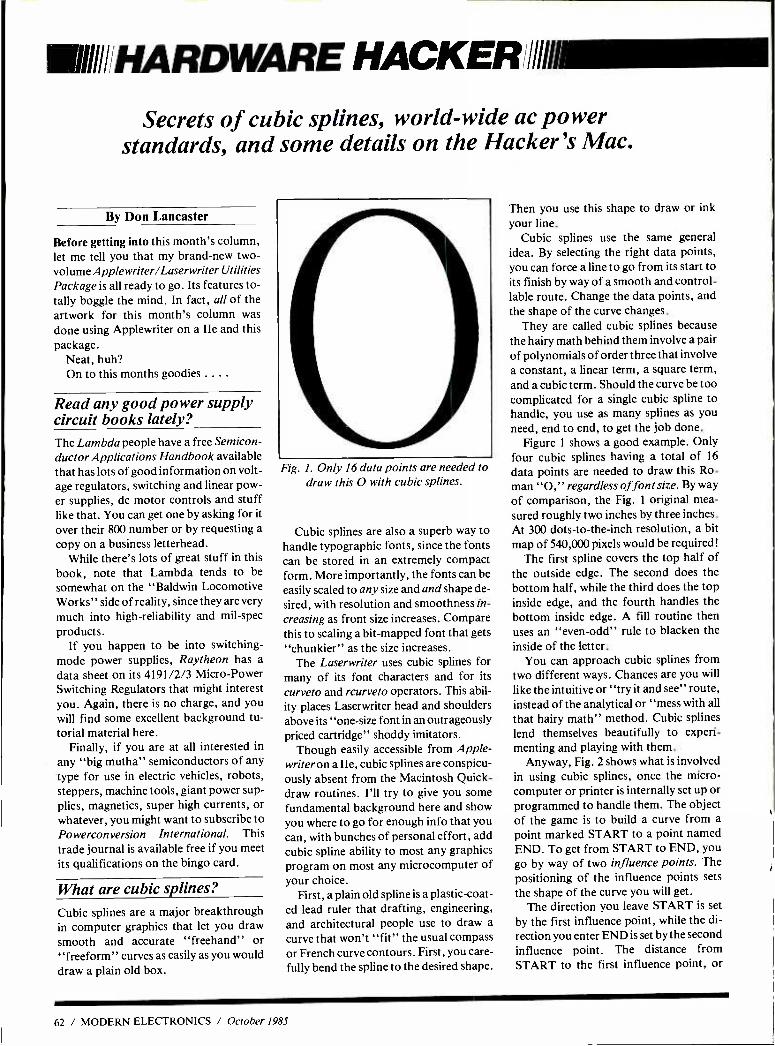
VIII HARDWARE HACKER/IIIIll1111111=M
Secrets of cubic splines, world -wide ac power standards, and some details on the Hacker's Mac.
By Don Lancaster
Before getting into this month's column, let me tell you that my brand -new two - volume Applewriter /Laserwriter Utilities Package is all ready to go. Its features to- tally boggle the mind. In fact, all of the artwork for this month's column was
done using Applewriter on a Ile and this package.
Neat, huh? On to this months goodies ... .
Read any good power supply circuit books lately? The Lambda people have a free Semicon- ductor Applications Handbook available that has lots of good information on volt- age regulators, switching and linear pow- er supplies, dc motor controls and stuff like that. You can get one by asking for it over their 800 number or by requesting a
copy on a business letterhead. While there's lots of great stuff in this
book, note that Lambda tends to be somewhat on the "Baldwin Locomotive Works" side of reality, since they are very
much into high -reliability and mil -spec products.
If you happen to be into switching - mode power supplies, Raytheon has a
data sheet on its 4191/2/3 Micro -Power Switching Regulators that might interest you. Again, there is no charge, and you will find some excellent background tu- torial material here.
Finally, if you are at all interested in
any "big mutha" semiconductors of any type for use in electric vehicles, robots, steppers, machine tools, giant power sup- plies, magnetics, super high currents, or whatever, you might want to subscribe to Powerconversion International. This trade journal is available free if you meet its qualifications on the bingo card.
What are cubic splines?
Cubic splines are a major breakthrough in computer graphics that let you draw smooth and accurate "freehand" or "freeform" curves as easily as you would
draw a plain old box.
Fig. I. Only 16 data points are needed to draw this O with cubic splines.
Cubic splines are also a superb way to handle typographic fonts, since the fonts can be stored in an extremely compact form. More importantly, the fonts can be easily scaled to any size and and shape de-
sired, with resolution and smoothness in-
creasing as front size increases. Compare this to scaling a bit -mapped font that gets "chunkier" as the size increases.
The Laserwriter uses cubic splines for many of its font characters and for its
curveto and rcurveto operators. This abil- ity places Laserwriter head and shoulders above its "one -size font in an outrageously priced cartridge" shoddy imitators.
Though easily accessible from Apple - writer on a Ile, cubic splines are conspicu- ously absent from the Macintosh Quick - draw routines. I'll try to give you some fundamental background here and show you where to go for enough info that you can, with bunches of personal effort, add cubic spline ability to most any graphics program on most any microcomputer of your choice.
First, a plain old spline is a plastic -coat- ed lead ruler that drafting, engineering, and architectural people use to draw a
curve that won't "fit" the usual compass or French curve contours. First, you care- fully bend the spline to the desired shape.
Then you use this shape to draw or ink your line.
Cubic splines use the same general idea. By selecting the right data points, you can force a line to go from its start to its finish by way of a smooth and control- lable route. Change the data points, and the shape of the curve changes.
They are called cubic splines because the hairy math behind them involve a pair of polynomials of order three that involve a constant, a linear term, a square term, and a cubic term. Should the curve be too complicated for a single cubic spline to handle, you use as many splines as you need, end to end, to get the job done.
Figure 1 shows a good example. Only four cubic splines having a total of 16
data points are needed to draw this Ro- man "O," regardless of font size. By way
of comparison, the Fig. 1 original mea- sured roughly two inches by three inches. At 300 dots -to- the -inch resolution, a bit map of 540,000 pixels would be required!
The first spline covers the top half of the outside edge. The second does the bottom half, while the third does the top inside edge, and the fourth handles the bottom inside edge. A fill routine then uses an "even -odd" rule to blacken the inside of the letter.
You can approach cubic splines from two different ways. Chances are you will
like the intuitive or "try it and see" route, instead of the analytical or "mess with all
that hairy math" method. Cubic splines lend themselves beautifully to experi- menting and playing with them.
Anyway, Fig. 2 shows what is involved in using cubic splines, once the micro- computer or printer is internally set up or programmed to handle them. The object of the game is to build a curve from a
point marked START to a point named END. To get from START to END, you go by way of two influence points. The positioning of the influence points sets
the shape of the curve you will get. The direction you leave START is set
by the first influence point, while the di-
rection you enter END is set by the second influence point. The distance from START to the first influence point, or
62 / MODERN ELECTRONICS / October 1985
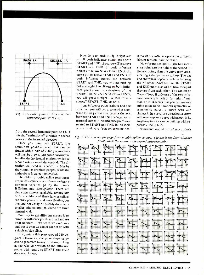
.
FIRST I.P. SECOND I.P.
START END
Fig. 2. A cubic spline is drawn via two "influence points" (I.P.$).
from the second influence point to END sets the "enthusiasm" at which the curve moves in the intended direction.
Once you have left START, the smoothest possible curve that can be drawn with a pair of cubic polynomials will then be drawn. One cubic polynomial handles the horizontal motion, while the second takes care of the vertical. The di- rection you head in is called the bias by the computer graphics people, while the enthusiasm is called the tension.
The oldest of cubic spline techniques are called Bezier curves. Newer and more powerful versions go by the names B- Splines and Beta -splines. There are also conic splines, available, among lots of others. Many of these fancier splines are more powerful and more flexible, but they are not easily or quickly done on a smaller microcomputer. Some are three dimensional.
One way to get different curves is to move the influence points around and see what happens. Let's see if we can't sec- ond -guess what we can or cannot do with a single cubic spline.
First, rotate this page around 360 de- grees. Obviously, the same shape curve can be generated in any direction, so long as the relative position of the influence points with regard to START and END does not change.
Now, let's get back to Fig. 2 right side up. If both influence points are above START and END, the curve will be above START and END. If both influence points are below START and END, the curve will be below START and END. If both influence points are between START and END, you will get nothing but a straight line. If one or both influ- ence points are on extensions of the straight line between START and END, you will get a straight line that "over- shoots" START, END, or both.
If one influence point is above and one is below, you will get a somewhat sine - wave- looking curve that crosses the axis between START and END. You get sym- metrical curves if the influence points are related to START and END in the same or mirrored ways. You get asymmetrical
curves if one influence point has different bias or tension than the other.
Now for the neat part. If the first influ- ence point is to the right of the second in- fluence point, then the curve may cross, creating a sharp cusp or a loop. The size and sharpness depends on how far away the influence points are from the START and END points, as well as how far apart they are from each other. You can get an "open" loop if only one of the two influ- ence points is far left or far right of nor- mal. Thus, it seems that you can use one cubic spline to do a smooth symmetric or asymmetric curve, a curve with one change in its curvature direction, a curve with one cusp, or a curve with a loop in it. Anything fancier can be built up with re- peated cubic splines.
Sometimes one of the influence points
Fig. 3. This is a sample page from a cubic spline catalog. The dot is the first influence point, while the square is the second influence point.
October 1985 / MODERN ELECTRONICS / 65
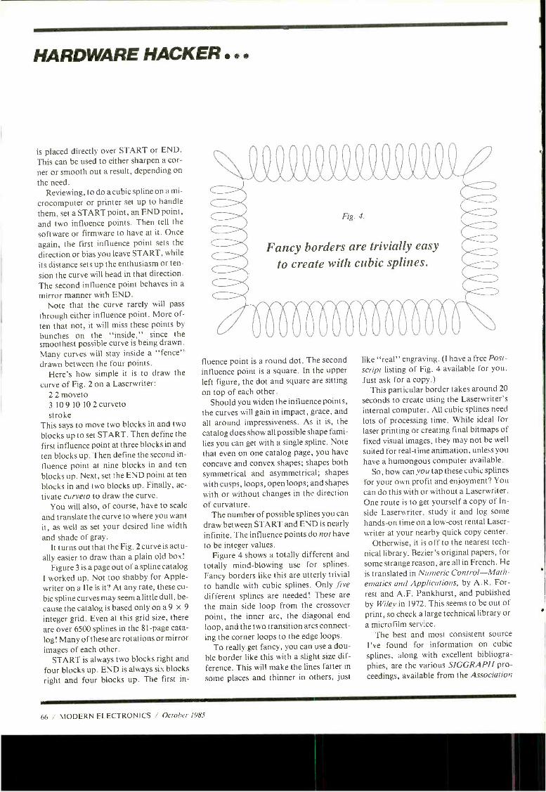
HARDWARE HACKER ..
is placed directly over START or END.
This can be used to either sharpen a cor-
ner or smooth out a result, depending on
the need. Reviewing, to do a cubic spline on a mi-
crocomputer or printer set up to handle
them, set a START point, an END point, and two influence points. Then tell the
software or firmware to have at it. Once
again, the first influence point sets the
direction or bias you leave START, while
its distance sets up the enthusiasm or ten-
sion the curve will head in that direction. The second influence point behaves in a
mirror manner with END. Note that the curve rarely will pass
through either influence point. More of-
ten that not, it will miss these points by
bunches on the "inside," since the smoothest possible curve is being drawn. Many curves will stay inside a "fence" drawn between the four points.
Here's how simple it is to draw the
curve of Fig. 2 on a Laserwriter: 2 2 moveto 3 10 9 10 10 2 curveto stroke
This says to move two blocks in and two
blocks up to set START. Then define the first influence point at three blocks in and ten blocks up. Then define the second in-
fluence point at nine blocks in and ten
blocks up. Next, set the END point at ten
blocks in and two blocks up. Finally, ac-
tivate curveto to draw the curve. You will also, of course, have to scale
and translate the curve to where you want it, as well as set your desired line width
and shade of gray. It turns out that the Fig. 2 curve is actu-
ally easier to draw than a plain old box!
Figure 3 is a page out of a spline catalog I worked up. Not too shabby for Apple - writer on a IIe is it? At any rate, these cu-
bic spline curves may seem a little dull, be-
cause the catalog is based only on a 9 x 9
integer grid. Even at this grid size, there are over 6500 splines in the 81 -page cata-
log! Many of these are rotations or mirror images of each other.
START is always two blocks right and
four blocks up. END is always six blocks
right and four blocks up. The first in-
Fancy borders are trivially easy
to create with cubic splines.
fluence point is a round dot. The second influence point is a square. In the upper left figure, the dot and square are sitting
on top of each other. Should you widen the influence points,
the curves will gain in impact, grace, and
all around impressiveness. As it is, the
catalog does show all possible shape fami- lies you can get with a single spline. Note that even on one catalog page, you have
concave and convex shapes; shapes both symmetrical and asymmetrical; shapes with cusps, loops, open loops; and shapes with or without changes in the direction of curvature.
The number of possible splines you can draw between START and END is nearly infinite. The influence points do not have
to be integer values. Figure 4 shows a totally different and
totally mind -blowing use for splines. Fancy borders like this are utterly trivial to handle with cubic splines. Only five different splines are needed! These are
the main side loop from the crossover point, the inner arc, the diagonal end
loop, and the two transition arcs connect- ing the corner loops to the edge loops.
To really get fancy, you can use a dou- ble border like this with a slight size dif-
ference. This will make the lines fatter in
some places and thinner in others, just
like "real" engraving. (I have a free Post- script listing of Fig. 4 available for you.
Just ask for a copy.) This particular border takes around 20
seconds to create using the Laserwriter's internal computer. All cubic splines need
lots of processing time. While ideal for laser printing or creating final bitmaps of fixed visual images, they may not be well
suited for real -time animation, unless you
have a humongous computer available. So, how can you tap these cubic splines
for your own profit and enjoyment? You
can do this with or without a Laserwriter. One route is to get yourself a copy of In-
side Laserwriter, study it and log some hands -on time on a low -cost rental Laser - writer at your nearby quick copy center.
Otherwise, it is off to the nearest tech- nical library. Bezier's original papers, for some strange reason, are all in French. He
is translated in Numeric Control -Math- ematics and Applications, by A.R. For- rest and A.F. Pankhurst, and published by Wiley in 1972. This seems to be out of print, so check a large technical library or a microfilm service.
The best and most consistent source I've found for information on cubic splines, along with excellent bibliogra- phies, are the various SIGGRAPH pro- ceedings, available from the Association
66 / MODERN ELECTRONICS / October 1985
MÄáT° 508 Central Ave.
WeatliOid, N.J. 07090 (201) 854-8008 /
Coils For Radio Elec's Feb. 84 TV Project, Toko WS T -1, T -2, L-1 (12uH) 8 L -2 (.071 uH) Complete Sat 01 All 4 Colla 8 50 MC1330- Prime (Moto) 2/1.00 BFO-85 Transistor 1 50 Disc Caps .001 of 20/1D0 74123 -Prime (Net) 3/1.00 470uí 35V (Radial) 3/1.00 470uí 18V (Axial) 4/1.00 2N3904 10/1.00 2N3906 10/1.00 1 N914 40/1.00 1N4148 40/1.00 1 N5231 B (5.1 V.Zener Diode) 5/1 00
78 27 824,7905 79 2 MT oor Match -3/ 00 Vlta Voltage (Unmarked, 60%
k% Mme) /May Include Posdive'Neg 8 Adjust 15/1.00 78L08 Voltage Reg( DM 106,10-92)20/ 1.00 PN2222A 20/1.00 2N3055 .50
15 (.15) Per IC TTL 20 /1.00
7403 7440 7495 7410 7442 74107 7436 7450 74151 7437 7474 74163 7438 7476 74393 15 Cant (.15) Per IC 74LSXX 74LS10 74LS86 74LS174 74LS20 741_5153 74LS257 74LS74 741.5158 74LS273 20 Cant (.20) Per IC CMOS 40018.4 11B, 40508
Opto (Ssolaattor(H11 G2.6PIN DIP) Specs 1.40 2716 Eprom 1 45 2732 Eprom 1 95 2784 Eprom 245 256K Dram 150ns Prime Hitachi (Ideal For Mac Upgrades8 Expansion Projects)... 4.95 8243(1/0 Expander IC) W/Specs 2 95 UDN 6118 (Display Driver IC- Specs) 85 UDN 6126 " UCN 41168.Osc/Freq Div Clock IC- Specs-5 //1 UCN 4801 (8 Chan Bi-Mos LatctVDriver)-1.00
LM380(ULN2280) .45 555 Timers (Ti) /1.00 NE556 (Dual Timer -Moto .50 741JOpAmp(Mini Dip Hi Rol Pkg) ...4/1.00 LM 1310 (Unmarked, Tested Prime) .....50 LM1889 .95 LM3900 45 AM /FM Radio IC (*2204 W /Specs -Hobby)
15/1.00 IC Sockets
8 Pin /.07, 14 Pin /.13. 16 Pin/ 15, 18 Pin /.17, 24 Pin /22, 28 Pin /.24 TO-5 Transistor Socket 7/1D0
7 Segment Display).3" 7 Segment D!splay(.6 Tri State LED's Jumbo Red LED's All 100% Prime-15/51, LED Mounting Texas InsV *994A Pins Made When Dip Switch -12 Dip Switch -8 Keyboard Push Audio Cable 22AWG Wire 27AWG Wire Mini Lubricator Soldering Iron Solder Sucker Molex Pins(7 Clock Module Display/ 12VOCTrne Rotary Switch Grant Alpha 7X5 (35 Total) 11 LED Bar LED's(Spectì7lyRed,Grn
Aired or(.5V,9V,1 Wall Plug Transformer 6.3V 1.2A Transformer 12V Center Tap Mini Audio Transformers 1N4007 1 N5059 200V 1N5060 (400V Zener Diodes-20V Zener Diodes-13V 2560.OKC Crystal 3.579545 ColorBurst 1.0 Mhz Crystal 6.0 Mhz Crystal TO-5 Heat Sinks TO-18 Heat Sinks Super Sub-PA .0015uf100V .0022uf100V .0027u1 100V .0033u1100V .0039u1100V .0056u1 100V 0082uí 100V 4.7uí 40V Lytic 47uí 25V Lytic 1000uí 185V Twist 3200uí 501 Ideal 5600uí 25V (Comp .1 of 50V Monolithics 22uí 50V Monolithics Chip Caps -Set .33uí 100V Dip .022uí 200V Wrapped 1 of 50V Wrapped 1,000 PC Resistor
Clips
Each Position
Position Button
(¡8
(201N)
Pir/Strip1100/$2, -Crystal
(5 Numeric
Red Graph
Transformer
1 Amp) 1 Amp)
(Bern) (Bern)
ni Ceramic 152 182 272 332 392 562 822 (Radial)
(Radial)
For
of 4 Mylar
Ass't
CommonGath) ....15 "CommonAnn) . ..65
3/100 -Diffused Lens, Prime (Ti)
100/$6,1,000/$57.50 B Rings 15/1.00
Keyboard- Inc/Data For Key Depressed. 4.95
2/1.00 4/1.00
Tops 30/1.00 30 Feet/1.00 50 Feet/1.00 50 Feet /1.00
Lubricant) ... 1.00 5 50
500/$4,1K/86 Controlled, Green
Set Switches/Data -4.95 Position, 5A 12514-3/1.00
Display 1.1/2" x 2' LED Matrix/Specs -4.95
Display -2.3/4 ", Rect Amb)Specs ... 2.69
V.185)RRegShpg 8.95 -241 525mA.... 1.50
1 20 2.50
10/1.00 20/1.00 15/1.00 10/100
1W 30/1.00 1W Glass 30/1.00
50 Crystal(HC -18) ....50
1 95 1 95
10/1.00 10/1.00
Cps (Alt 100V) 30/100 30/1.00 30/1.00 30/1.00 30/1.00 30/1.00 30/1.00 20/100 10/1.00
Lock 1 00 Power Supplies) -1.00
Grade 3-5/8"X11-3/1.00 10/1.00 20/1.00
2 Each 2.7 8 3.3pí -1.00 10/1.00
Mylar 15/1.00 Mylar 15/1.00
(30 Values) 1/2W -$3
Pots -1 Meg, Linear Taper 5 /1.00 Motion Detector Bds (Inc IC-S2) ... 7/10.00 Mot Del IC Only- ULN2232N 3/82- 20/10.00 Project Box/Lid For Detector 1.95 Miniature Speaker For Detector 25 Extensive Construction Article For Det. $1
Knobs er (0.15 A.C. Amperes)
15/1.00 95 Amme
Vo1VOHM Meter MVMNT (0-1K OHM, 0.3001) 2 95
6V Miniature Gear Motor .50 RFChokes- 1.8uh,8.2uh 12uh22uÁ10/1.00 22/44 Pin Edge Card Connector .50 34 PinConnector(For Drives) W /Hood.....75 BNC "T" Connector(UG-274) .95 Mixed Connector Ass't 10/1.00 1.5AMP 50V Bridge (GI, TO-5 Pkg) .50 25AM P 200V Bridge ( Soder Lug Tenn) 1.50 Zenith TV Replacement IC 81)1=181111 Each 221-42, 221 -43, 221 -45, 221-48, 221 -69, 221-79,221-87,221-96,221-104, 221 -105, 221-106 221 -140 2$0900 Horiz Output W /Damper Diode) -2.95 2$0117 B(Toshib-Horiz Output Trans) -1.95 Winegard 4 Bay Bowtie UHF Antenna-19.50
Box (Holds) 30 ICs-1.75 IC Storage Precision
500 OHM, rK 2K SPK 10k. 20K 50K 100K 200K, 500K 1M-.85 Eech -3/52 MherPTl VHa (SIngleTum n Trimme 100 OHM, 1 K 10K 25K 50K, 100K ... 4/51 Heat Sensitive Switch /150' C 10/1.00 Mixed Switch Ass't 10/1.00 Mixed Cod Asst 10/1.00 Rubber Feet 10/1.00 Buzzers 3/1.00 Chip Resistor 6.811 20/1.00 Chip Resistor )47010 20/1.00 Chip Cap )330pf) 20/1.00 Jumbo Red LEE6D W /Built In Resistor -30/51 MRF901(HobbyGrade80% 10/1.00 De- Soldering Braid 35-Wick) 5 Ft .90 IC Ass't (Hobby Grade. Some Marked) -30/51
a. f
20 Cent (.20) 74SCXX Series Special
Octal Interface Circuits Equivalent To 74LSXX Serles Low Power ISO-CMOS Technology Short Propagation Delay Improved Noise Margins High Current, Sink/Source Capability
745C137 -1 Of 8 Inverted Decoder. Latched 7490138 -1 Of8 Inverted Decoder 74SC139-1 Of4 Inverted Decoder 74SC237 -1 Of 8 Non -Inverted, Latched 74SC238-1 018 Non -Inverted 7450239 -1 014 Non -Inverted 745C240-Octal Butter /Line Driver -Inv 74SC241 -Octal Butter /Line Driver -N /I 74SC244 -Octal Butter /Line Driver -N /I 74SC245 -Octal Bus Transceiver -Non'! 745C373-Transparent Latch- Non /Inv
7450374 -D Type Flip -Flop. Non /Inv 74SC533- Transparent Latch -Inverted 74SC534 -D Type Flip-Flop Inverted 74SC540-Octal Buffer /Line Driver -Inv 745C541-Octal Buffer /Line Driver -N /I 74SC563- Transparent Latch. Inverted 74$0564 -D Type Flip -Flop, Inverted 74SC573-Transparent Latch Non /Inv 74SC574 -D Type Flip -Flop. Non /Inv Data Book For All Above as 2 50
Cypher IV Micro-Controller Kit -5119.50 4 MHz, 8 -Bit Microprocessor
(NAT 1 NS8073) Control Basic Interpreter On -Chip Auto-Start Operation At Power -On Fast 16 -Bit Multiply And Divide RS -232, Supports CATS Serial Link 24 Bi- Directional I/O Lines 18255Aí RAM Memory-2K Expandable To 16K Eprom Memory-Expandable To 16K Built In Eprom Programmer Parr ICenlronix Printer Interface Optional Real -Time Clock W /Backup
Pay TV Hardware Installation Kit Blow Out As Low As 52.95 + S3.50 Shipping Per Unit All Kits Contain 5 F Connectors. 300 to 74 OHM Balun 300 OHM Terminal Block 2 Ft 75 75 OHM Patch Cord 2 Ft 300 OHM Twin Lead. Nylon Cable Ties, And UHF Antenna Model *4124.82.95 Includes All Of The Above Plus 25 Feet Coaxial Cable And Mounting Hardware For Indoor Wall /Ceding Installation Modal 44880 -$2.95 Includes All Of The Above Plus 25 Feet Coaxial Cable And Attractive Expandable Pole /U-Bolt For Easy Indoor Installation Model *4845 -$3.95 Includes All Of The Above Plus 65 Feet Coaxial Cable Am; All Necessary U -Bolt Hardware
MODEL 705 Digital Multimeter
Dc Volage AC Voltage Dc current AC Current HI-1.0 Resistance Capacitance Node Tat Hrr tai
r00rV to 1000V 100pV to 750V o.l eA to 10A 0.1/1A to 10A 0.14 to 20M4 tpF to 20CF loread voltage rating transistor testing
5195
UHF -TV PREAMP (As featured in Radio Electronics March/ May articles. 1982) this inexpensive antenna mounted pre - amp can add more than 25 dB of gain to your system. Lots of satisfied customers and repeal orders for this high quality kit, which includes all component parts. PC BD, Case. Power Supply and Balun $34.50 Assembled Version $5750
Tema MICRO -MART accepts Visa MC and telephone CODs Minimum Order $1000 Shipping - U.S orders, $2.00 Canada and other countries 83 50 (includes ins) Shipping rate adjusted where applicable. NJ residents add 6% sales tax MICRO-MART 500 CENTRAL AYE., WESTFIELD. NJ 07090 (201( 6544006
CIRCLE NO. 127 ON FREE INFORMATION CARI)
CHANGE OF ADDRESS
MODERN ELECTRONICS 76 N. Broadway, HICkslrile, NY 11801
Planning to move? Please let us know six weeks in advance so you won't miss a single issue of MODERN ELECTRONICS Attach old label and print new address In space provided. Also Include your mailing label whenever you write concerning your subscription to ensure prompt service on your Inquiry.
ATTACH LABEL HERE
PLEASE PRINT NAME
ADDRESS
CITY STATE
DATE ZIP
Complete Schematics & Logic Diagrams
o Your Computer, Printer, Monitor, Disk Drives Whether you want to modify your computer system, repair it, or Just understand It, COMPUTERFACTS will make it happen. And It's so easy:
TAKEN NGI TE PRESSING THE THE A KEY
- fry .22v 'i 741.5175PC
Complete schematics Detailed explana- tions Pans list cross referenced to standard parts Disassembly Instructions Wiring diagrams ' Proper waveforms a voltages shown on schematics Troubleshooting techniques Block diagrams Test points Identified as high, low, or pulsing Quick parts location using grid -lined photographs
And much, much more!
For a limited time at low, introductory prices: Apple II 8 II Plus (together), Ile, Epson MX- 80F/T, MX -100, FX -80. A2M0003 disk drive, A3M0039 monitor, FX -100 printers $19 each Imagewriter printer $19 each
Radio Shack TRS -80 26 -1164 disk ATARI 400, 800 computers $19 each drive, 26 -1160 disk drive, DMP -120
printer $19 each Commodore 64 computer, 1541 disk drives, 1525 printer, 16 computer, 1701 Zenith ZVM -121, ZVM- 122A/123A. monitor, Plus /4 computer $19 each ZVM -131, ZVM -135 monitors $19 each
SPECIAL! COMPUTERFACTS for complete IBM PC system: keyboard, system board, power supply, disk drives, and printer adapter and color and monochrome adapters. All for only $37.50. Apple 11c, ATARI 800XL, Epson OX -10, IBM PCjr, TRS -80 Model 1 or Model III, Zenith Z150 systems. Only $39 each.
Plus many others. Write for list. Shipping and handling $3 first set, $1 each additional set. CA residents add 6% sales tax.
Visa /MC /AmEx ORDERS CALL: 1 -800- 443 -0100, Ext 540
or mail to Computing Technology, P.O. Box 1298, Ridgecrest. CA 93555
C IR('.I t 71 ON FREE INFORMATION CARD
HARDWARE HACKER
for Computer Machinery. These usually appear in the number -three issue of each year's ACM Computer Graphics quarter- ly. The 1983 and 1984 proceedings are es-
pecially useful. I've yet to see the 1985
SIGGRAPH stuff. The advance promo- tion promises one paper on conic splines.
An obvious money- making idea that involves splines would be to apply them directly to Apple or other HIRES graph- ics routines, so that free -form curves can be handled as gracefully as ordinary boxes can. They are also sorely needed by the Mac. What would be really neat is to be able to real -time move the influence points around.
Let me know what you discover in this fascinating new area.
What ac power plugs get used where in the world at what voltage and frequency? Did you know that the vast majority of countries in the world use 220 volts, 50 Hz
as their primary power standard? Or that some buildings in some developing coun- tries actually may have several different power lines connected to several different and totally incompatible power systems?
Did you also know that there are at
least 10 different major sizes and shapes of ac power plugs and sockets, all totally incompatible with each other?
This might affect you if you are plan- ning to travel and take a computer or test gear with you, or if you are being assigned to a foreign office, or if you are designing products you want to sell world -wide. You might also be interested in this if you
are catering to international tourists. What is used how and where? There's a great free book called Inter-
national Primary Power Components. This combined reference and catalog is
published by Panel Components Corp. It tells you all about all the voltages, fre- quencies and connectors as they are used everywhere in the world. As usual, you
NAMES AND NUMBERS
Golemics 2600 Tenth Street Berkeley, CA 94710 (415) 486-8344
Inside Laserwriter 467 Saratoga Avenue S621
San Jose, CA 95129 (408) 988-6009
Lambda Semiconductors 121 International Drive Corpus Christi, TX 78410 (800) 255 -9606
Panel Components Corp. Box 6626 Santa Rosa, CA 95406 (707) 578-5478
Powerconversion International 2472 Eastman Avenue U -34
Ventura, CA 93003 (805) 658-0933
Raytheon Semiconductor 350 Ellis Street Mountain View, CA 94039 (415) 968-9211
SIGGRAPH ACM 11 West 42nd Street New York, NY 10036 (212) 869 -7440
Howard W. Sams 4300 West 62nd Street Indianapolis, IN 46206 (800) 428 -SAMS
Synergetics Box 809 Thatcher, AZ 85552 (602) 428-4073
John Wiley & Sons 605 Third Avenue New York, NY 10158
(212) 850-6000
get a copy by way of a request on a busi-
ness letterhead or by telephone request. Most electronic equipment these days
have a removable cordset that plugs into a
standard three -prong socket called an IEC 320 connector. Among countless other places, you'll find these on Hewlett - Packard and Tektronix test equipment and on most personal computers.
All you may have to do to use test equipment in a different country is swap the cordset for the one that fits the ac wall
socket and flip a hidden or buried 110/ 220 switch to the proper position. But this can happen only if your piece of equip- ment operates either on both 110 and 220
volts or lets you switch between them. A 110 -volt anything could instantly
burn out on 220 volts! At the very least, all primary fuses will immediately blow.
While most modern electronic equip- ment can run at 50 or 60 Hz equally well,
many motors may not and could even be damaged. Any motors that are used for timing probably will run at the wrong speed. Certain phonograph turntables and clocks are obvious examples.
Be darn sure you read the label and check the switches before trying to run something at 220 volts or 240 volts. Con- versely, most equipment rated at 220 or 240 volts will not work at all on 110 or 120
volts. The extreme "brownout" can damage motors and such if they try to run too slow under too high a load.
Even if there is no 110/220 switch, the internal power supply in your computer or whatever may let you rewire the power transformer primary for 110 or 220.
Sometimes a pair of input windings is
provided. Wire them in parallel aiding for
110/120 volts or series aiding for 220/240 volts. Details will appear in the tech
manual for the instrument or computer in
use. As a general rule, if they don't tell
you about 220 -volt or 50 Hz operation, then you cannot do it.
The final option is to get an external 220/240 to 110/120 step -down trans- former big enough to handle the load. Plug the 220 side into the wall outlet and
68 / MODERN ELECTRONICS / October 1985
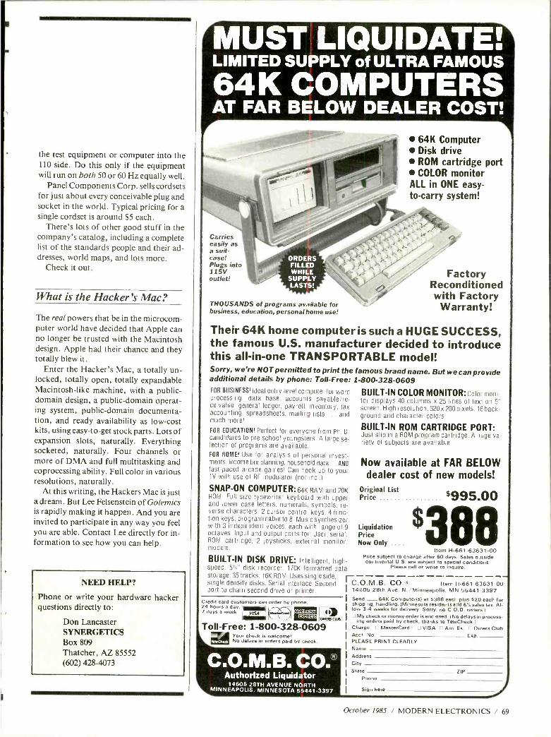
ti
the test equipment or computer into the 110 side. Do this only if the equipment will run on both 50 or 60 Hz equally well.
Panel Components Corp. sells cordsets for just about every conceivable plug and socket in the world. Typical pricing for a single cordset is around $5 each.
There's lots of other good stuff in the company's catalog, including a complete list of the standards people and their ad- dresses, world maps, and lots more.
Check it out.
What is the Hacker's Mac?
The real powers that be in the microcom- puter world have decided that Apple can no longer be trusted with the Macintosh design. Apple had their chance and they totally blew it.
Enter the Hacker's Mac, a totally un- locked, totally open, totally expandable Macintosh -like machine, with a public - domain design, a public- domain operat- ing system, public- domain documenta- tion, and ready availability as low -cost kits, using easy -to -get stock parts. Lots of expansion slots, naturally. Everything socketed, naturally. Four channels or more of DMA and full multitasking and coprocessing ability. Full color in various resolutions, naturally.
At this writing, the Hackers Mac is just a dream. But Lee Felsenstein of Golemics is rapidly making it happen. And you are invited to participate in any way you feel you are able. Contact Lee directly for in- formation to see how you can help.
NEED HELP?
Phone or write your hardware hacker questions directly to:
Don Lancaster SYNERGETICS Box 809 Thatcher, AZ 85552 (602) 428-4073
MUST LIQUIDATE: LIMITED SUPPLY of ULTRA FAMOUS
64K COMPUTERS AT FAR BELOW DEALER COST!
64K Computer Disk drive ROM cartridge port COLOR monitor
ALL in ONE easy - to -carry system!
Carries easily as a suit- case! Plugs into 115V outlet!
ORDERS FILLED WHILE
SUPPLY LASTS!
THOUSANDS of programs available for business, education, personal home use!
Factory Reconditioned with Factory
Warranty!
Their 64K home computer is such a HUGE SUCCESS, the famous U.S. manufacturer decided to introduce this all -in -one TRANSPORTABLE model! Sorry, we're NOT permitted to print the famous brand name. But we can provide additional details by phone: Toll -Free: 1- 800 -328 -0609 FOR BUSINESS! Ideal entry level computer for word processing. data base, accounts payable /re- ceivable, general ledger, payroll, inventory, tax accounting, spreadsheets, mailing lists ... and much more!
FOR EDUCATION! Perfect for everyone from Ph. D. candidates to pre -school youngsters. A large se- lection of programs are available. FOR HOME! Use for analysis of personal invest- ments, income tax planning, household data ... ANO fast -paced arcade games! Can hook up to your TV with use of RF modulator (not incl.).
SNAP -ON COMPUTER: 64K RAM and 20K ROM. Full size typewriter keyboard with upper and lower case letters, numerals, symbols, re- verse characters. 2 cursor control keys. 4 func- tion keys, programmable to 8. Music synthesizer with 3 independent voices, each with range of 9 octaves. Input and output ports for: User. serial, ROM cartridge. 2 joysticks, external monitor, modem
BUILT -IN DISK DRIVE: Intelligent, high- speed. 5' disk recorder. 170K formatted data
BUILT -IN COLOR MONITOR: Color moni- toi displays 40 columns x 25 lines of text on 5" screen. High resolution. 320 x 200 pixels. 16 back- ground and character colors
BUILT -IN ROM CARTRIDGE PORT: Just slip in a ROM program cartridge. A huge va- riety of subjects are available.
Now available at FAR BELOW dealer cost of new models!
Original List Price $995.00
Liquidation Price Now Only .. 88
Item H- 661- 63631 -00 Price subject to change after 60 days. Sales outside continental U.S. are subject to special conditions.
Please call or write to inquire.
storage; 35 tracks, 16K ROM. Uses single side, -- - single density disks. Serial interface. Second ' C.O.M.B. CO. R Item H -661- 63631 -00 port to chain second drive or printer. 14605 28th Ave. N. /Minneapolis. MN 55441 -3397
Credit card customers can order by phone, 24 hours a day, 7 days a week
lI nraeaw;av . !Di EXPRESS,
Toll-Free: 1- 800 -328 -0609 Your check is welcome' Ni, delays in orders paid by .:heck.
COMB. CO. Authorized Liquidator
14605 28TH AVENUE NORTH MINNEAPOLIS, MINNESOTA 55441 -3397
Send - 64K Computer(s) at $388 each plus $20 each for shipping, handling. (Minnesota residents add 6% sales tax. Al- low 3 -4 weeks for delivery. Sorry, no C.O.D. orders.) 17 My check or money order is enclosed. (No delays in process-
ing orders paid by check, thanks to TeleCheck.) Charge: O MasterCard. O VISA O Am. Ex. O Diners Club Acct. No. Exp PLEASE PRINT CLEARLY Name Address City State ZIP
Phone
Sign here
October 1985 / MODERN ELECTRONICS / 69
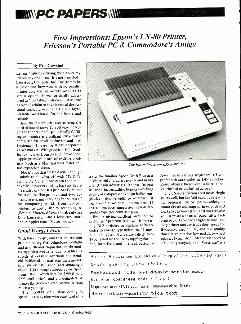
IIIi//PC PA PERS ill/
First Impressions: Epson's LX -80 Printer, Ericsson's Portable PC & Commodore's Amiga
By Eric Grevstad
Let me begin by denying the slander my
friends say about me: It's not true that I
hate Apple Computer Inc. The IIc may be
a closed -box bow -wow with no parallel printer port and the world's worst LCD screen option -it was originally adver- tised as "portable," which is just as true as Apple's claim to have invented the per- sonal computer -but the IIe is a loyal, versatile workhorse for the home and schools.
And the Macintosh, now gaining the hard disks and powerful software it need- ed a year and a half ago, is finally fulfill-
ing its promise as a brilliant, easy -to -use
computer for small businesses and pro- fessionals, if never for IBM's corporate office market. With president John Scul-
ley taking over from dreamer Steve Jobs, Apple promises a raft of exciting prod- ucts (such as a Mac that runs faster and has expansion slots).
No, it's not that I hate Apple- though I admit to showing off with MS -DOS, typing del *. bak in one -tenth the time it
takes Mac mousers to drag backup files to the trash can icon. It's just that I'd rather focus on the fine products and develop- ments appearing every day in the rest of the computing world, from low -cost
printers to exotic display technologies. (Besides, Modern Electronics already has Don Lancaster, who's forgotten more about Apples than I'll ever know.)
Good Words Cheap
With laser, ink -jet, and thermal- transfer printers taking the technology spotlight and new 18- and 24 -pin dot -matrix mod- els supplying typewriter quality at blazing speeds, it's easy to overlook one trend: old- fashioned dot -matrix printers are get- ting surprisingly good and amazingly cheap. I just bought Epson's new Spec-
trum LX -80, which lists for $299 (I paid $229 mail- order), and am delighted. A printer this good would have cost twice as
much a year ago. The LX -80's only shortcoming is
speed; its trusty nine -wire printhead gen-
The Epson Spectrum LX -80 printer.
erates the familiar Epson Draft Pica at a
mediocre 66 characters per second in my
tests (Epson advertises 100 cps). Its best feature is its versatility: besides switching to elite or compressed type (or italics, em-
phasized, double -width or whatever), it
can slow to a two -pass, unidirectional 15
cps to produce impressive near- letter-
quality type (see print samples). Besides giving excellent print for the
price, the Spectrum frees you from set-
ting DIP switches or sending software codes to change typestyles: the 11 most popular are part of a feature called Selec-
Type, available for use by tapping the on- line, form feed, and line feed buttons a
few times in various sequences. (If you prefer software codes or DIP switches, Epson obliges; there's even a switch to se-
lect slashed or unslashed zeroes.) The LX -80's friction feed holds single
sheets well, but fanfold paper is best with the optional tractor ($40)- which, to sound like an ad, snaps on in seconds and works like a charm (though it does require you to waste a sheet of paper after each print job). If you need a light- to medium - duty printer and can trade sheer speed for
flexibility, ease of use, and text quality that almost matches low -end daisy -wheel printers (which don't offer draft speed or 100 -odd typestyles), the "Spectrum" is a
Epson Spectrum LX --8O (:ira+t dual i ty pica (
quality pi c.: r.'i-al.i
Emphasized mode and double- strike mode
Elite or condensed mode (12 cpi)
Compressed mode (17.16 cpi) and compressed elite (20 cpi)
Near -letter -quality pica text
cpii
70 / MODERN ELECTRONICS / October 1985
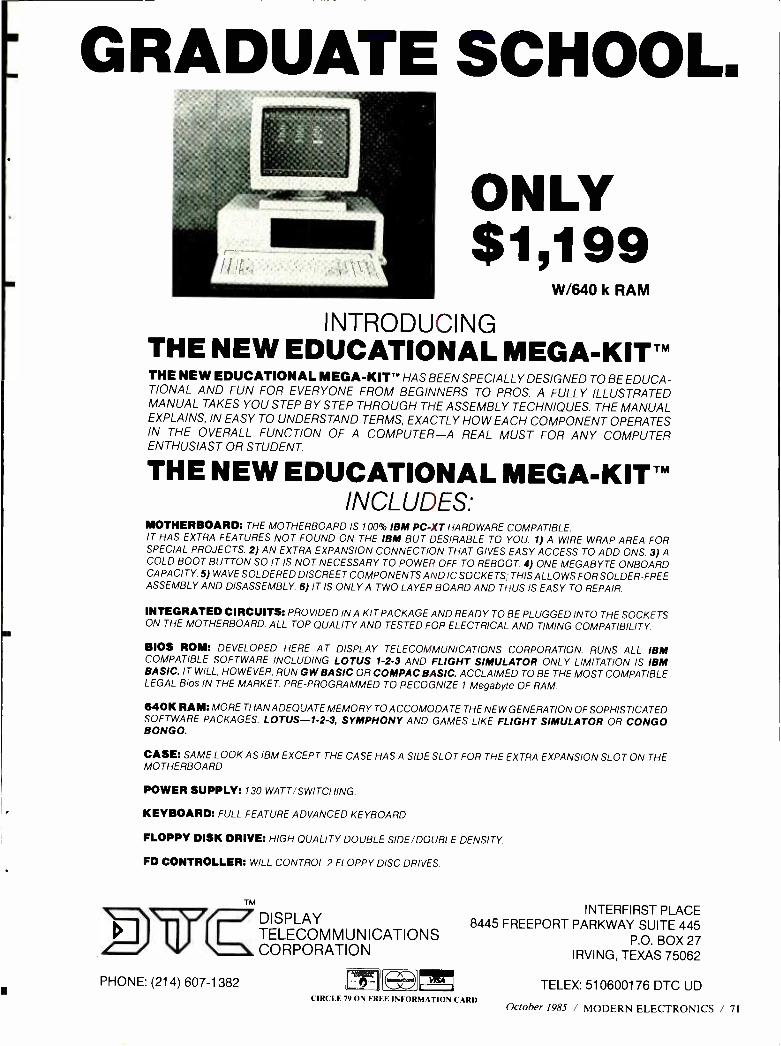
GRADUATE SCHOOL.
ONLY $1,199
W/640 k RAM
INTRODUCING THE NEW EDUCATIONAL MEGA -KITTM THE NEW EDUCATIONAL MEGA -KIT" HAS BEEN SPECIALLY DESIGNED TO BE EDUCA- TIONAL AND FUN FOR EVERYONE FROM BEGINNERS TO PROS. A FULLY ILLUSTRATED MANUAL TAKES YOU STEP BY STEP THROUGH THE ASSEMBLY TECHNIQUES. THE MANUAL EXPLAINS, IN EASY TO UNDERSTAND TERMS, EXACTLY HOW EACH COMPONENT OPERATES IN THE OVERALL FUNCTION OF A COMPUTER -A REAL MUST FOR ANY COMPUTER ENTHUSIAST OR STUDENT.
THE NEW EDUCATIONAL MEGA -KITTM INCLUDES:
MOTHERBOARD: THE MOTHERBOARD IS 100% IBM PC -XT HARDWARE COMPATIBLE. IT HAS EXTRA FEATURES NOT FOUND ON THE IBM BUT DESIRABLE TO YOU. 1) A WIRE WRAP AREA FOR SPECIAL PROJECTS. 2) AN EXTRA EXPANSION CONNECTION THAT GIVES EASY ACCESS TO ADD ONS. 3) A COLD BOOT BUTTON SO IT IS NOT NECESSARY TO POWER OFF TO REBOOT 4) ONE MEGABYTE ONBOARD CAPACITY. 5) WAVE SOLDERED DISCREET COMPONENTS AND IC SOCKETS; THIS ALLOWS FOR SOLDER -FREE ASSEMBLY AND DISASSEMBLY. 6) IT IS ONLY A TWO LAYER BOARD AND THUS IS EASY TO REPAIR.
INTEGRATED CIRCUITS: PROVIDED IN A KIT PACKAGE AND READY TO BE PLUGGED INTO THE SOCKETS ON THE MOTHERBOARD. ALL TOP QUALITY AND TESTED FOR ELECTRICAL AND TIMING COMPATIBILITY
BIOS ROM: DEVELOPED HERE AT DISPLAY TELECOMMUNICATIONS CORPORATION. RUNS ALL IBM COMPATIBLE SOFTWARE INCLUDING LOTUS 1 -2 -3 AND FLIGHT SIMULATOR ONLY LIMITATION IS IBM BASIC. IT WILL, HOWEVER, RUN GW BASIC OR COMPAC BASIC. ACCLAIMED TO BE THE MOST COMPATIBLE LEGAL Bios IN THE MARKET. PRE -PROGRAMMED TO RECOGNIZE 1 Megabyte OF RAM.
640K RAM: MORE THAN ADEQUATE MEMORY TO ACCOMODATE THE NEW GENERATION OF SOPHISTICATED SOFTWARE PACKAGES, LOTUS- 1 -2 -3, SYMPHONY AND GAMES LIKE FLIGHT SIMULATOR OR CONGO BONGO.
CASE: SAME LOOK AS IBM EXCEPT THE CASE HAS A SIDE SLOT FOR THE EXTRA EXPANSION SLOT ON THE MOTHERBOARD
POWER SUPPLY: 130 WATT /SWITCHING.
KEYBOARD: FULL FEATURE ADVANCED KEYBOARD.
FLOPPY DISK DRIVE: HIGH QUALITY DOUBLE SIDE /DOUBLE DENSITY.
FD CONTROLLER: WILL CONTROL 2 FLOPPY DISC DRIVES.
TM
EVE PHONE: (214) 607 -1382
DISPLAY TELECOMMUNICATIONS CORPORATION
CD
INTERFIRST PLACE 8445 FREEPORT PARKWAY SUITE 445
P.O. BOX 27 IRVING, TEXAS 75062
CIRCLE 79 ()N FRF E INFORMATION CAR»
TELEX: 510600176 DTC UD
October 1985 / MODERN ELECTRONICS / 71
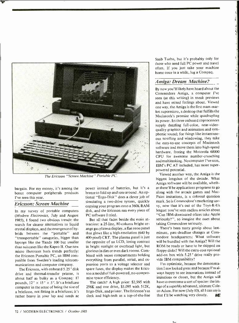
The Ericsson "Screen Machine" Portable PC.
bargain. For my money, it's among the better computer peripherals products I've seen this year.
Ericsson: Screen Machine In my survey of portable computers (Modern Electronics, July and August 1985), I found two obvious trends: the search for clearer alternatives to liquid crystal displays, and the emergence of hy- brids between the "portable" and "transportable" catagories, bigger than laptops like the Tandy 100 but smaller than suitcases like the Kapro II. One new micro illustrates both trends perfectly: the Ericsson Portable PC, an IBM com- patible from Sweden's leading telecom- munications and computer company.
The Ericsson, with onboard 5.25 " disk drive and thermal- transfer printer, is
about half as bulky as a Compaq: 17
pounds, 12 " x 15 " x 5 ". It's a briefcase computer in the sense of being the size of a briefcase, not fitting in a briefcase; it's rather heavy in your lap and needs ac
power instead of batteries, but it's a
breeze to fold up and tote around. An op- tional "Ergo- Disk" does a clever job of simulating a two -drive system, quickly copying your program onto a 360K RAM disk, and the Ericsson ran every piece of PC software I tried.
But all that fades beside the main at- traction: a 25 -line, 80- column bright or- ange gas plasma display, a flat neon panel that glows like a high -resolution (640 by 400- pixel) CRT. The plasma panel is just the opposite of an LCD, losing contrast in bright sunlight or overhead light, but glorious in dim or even dark rooms. Com- bined with secret compartments holding everything from parallel, serial, and ex-
pansion ports to a voltage selector and spare fuses, the display makes the Erics- son a model of full -powered, no- compro- mise space efficiency.
The catch? A high price: $2,995 with 256K and one drive, $5,095 with 512K, Ergo -Disk, and printer. The Ericsson's as
sleek and high -tech as a top -of- the -line
Saab Turbo, but it's probably only for those who need full PC power and travel often. If you just take your machine home once in a while, lug a Compaq.
Amiga: Dream Machine? By now you'll likely have heard about the Commodore Amiga, a computer I've seen (at this writing) in sneak previews and have mixed feelings about. Viewed one way, the Amiga is the first mass -mar- ket supermicro, a desktop that fulfills the Macintosh's promise while quadrupling its power. Its three onboard coprocessors supply dazzling full -color, near- video- quality graphics and animation and sym- phonic sound; for things like instantane- ous scrolling and windowing, they take the easy -to -use concepts of Macintosh software and move them into high -speed hardware, freeing the Motorola 68000 CPU for awesome number -crunching and multitasking. No computer I've seen, IBM's PC AT included, has more super - powered potential.
Viewed another way, the Amiga is the biggest longshot of the decade. What Amiga software will be available, wheth- er there'll be applications programs to go along with the arcade games and Mac - Paint imitations, is a colossal question mark. So is Commodore's marketing sav- vy, now that it's out of the Toys -R -Us
league: you've seen endless articles about "Can IBM -dominated ofices take Apple seriously ? ", so imagine the ones about taking Commodore seriously.
There's been nasty gossip about last - minute, past- deadline changes at Com- modore headquarters: What software will be bundled with the Amiga? Will the ROM be ready or have to be shipped on floppy disks? Will the extra -cost optional add -on box with 5.25 " drive really pro- vide IBM compatibility?
I'm optimistic, because the demonstra- tion I saw looked great and because I'm al- ways happy to see innovations instead of imitations or clones, but the Amiga will
have to overcome a sort of specter: the im-
age of a superbly advanced, ultimate Cole- co Adam. For now (July 10), all I can say is
that I'll be watching very closely. IUE
72 / MODERN ELECTRONICS / October 1985
A Great Gift Idea DON'T LET THE ELECTRONICS REVOLUTION PASS YOU OR A FRIEND BY! SUBSCRIBE TO
IMODELEaEromcs
Now you can reach out every month and learn about the latest innovations in consumer electronics and personal computers- what's new, how products and circuits work, and what leading authorities think of them.
*Stereo *Video *Home & Car Electronics *Test Instruments *Circuitry & Devices *Servicing
*Personal Computers *Communications *Construction Projects In every issue, authors lucidly explain how exciting, new
electronics ideas are applied ... issue forthright buying counsel ... present complete plans to build electronic devices to enhance products, even unique ones that are not yet being sold in the marketplace.
Feature articles, tutorials, and construction projects are the hallmarks of MODERN ELECTRONICS, the new monthly magazine for electronics and computer enthusiasts. Covering the entire spectrum of these fields, you'll gather insights in every important area to help you make buying decisions for work and play purposes ... improve performance of your present equipment ... increase your electronics competence ... and add to your practical and intellectual knowledge of electronics and computers.
To be sure you get this valuable information delivered to you regularly, and share the experiences of our writers and edi- tors- Forrest Mims, Len Feldman, Stan Prentiss, Charles Ru- benstein, Glenn Hauser, and many others -you can subscribe to MODERN ELECTRONICS today. As a Charter Subscriber, you'll save 45% off the newsstand price when you buy a one - year subscription for only $12.97. Or save 51% when you sub- scribe for two years at $22.97.
Just fill out the coupon and mail with your check, money order, or credit card information (Visa or MasterCard) to enter your Charter Subscription. Do it today to ensure earliest delivery!
MODERN ELECTRONICS 76 North Broadway, Hicksville, NY 11801
Please send me Modern Electronics for 2 Years 1 Year
Name
Street
City State Zip
2 Years (24 issues) $22.970
1 Year (12 issues) $12.970
Charge My Order To: Payment Enclosed $
[ ] MasterCard
VISA My acc*aat somber b:
1 1 1 1 1 1 1 1 1 1 1 1 1 1 1
With so many electronic catalogs out there, how does MCM stay at the top?
We strive to bring you the
best catalog in the industry. You'll find
our 132 page catalog packed with a full
line of test equipment, computer acces- sories, speakers, CATV equipment,
television parts and the largest selection of original Japanese
semiconductors in the country. Our product
selection puts us at the top; our low prices
and fast delivery are what keep
us there! CALL TODAY FOR YOUR FREE COPY OF CATALOG #10!
CALLTOLL FREE 1- 800 - 543 -4330
(]N OHIO CALL 1- 800 -762 -4315) (IN HAWAII OR ALASKA 1 -800- 858 -1849)
0 MCM ELECTRONICS A Olvaun OF VMEMEP MOUM W.
858 East Congress Park Drive Centervae, 01úp 45459 513- 434 -0031
SOURCE NO. ME -5
CIRCLE 85 ON FREE INFORMATION CARD
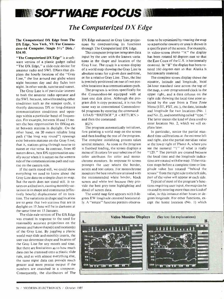
IIIiI'SOFT WARE FOCUS illl111
The Computerized DX Edge
The Computerized DX Edge from The DX Edge, New York, NY/For Commo- dore-64 Computer. /Single 5V2" Disk./ $34.95.
"The Computerized DX Edge" is a soft- ware version of a plastic gadget called "The DX Edge," a slide -rule device for amateur radio and SWL DXers that dis- plays the hourly location of the "Gray Line," the line around our globe where night becomes day and day fades into night. In other words, sunrise and sunset.
The Gray Line is of particular interest to both the amateur radio operator and the SWL because, notwithstanding other conditions such as the sunspot cycle, it sharply determines DX or long- distance communications conditions and open- ings within a particular band of frequen- cies. For example, between 10 and 15 me- ters the best opportunities for DXing ex- ist between stations in daylight. On the other hand, on 20 meters reliable long path ( "the long way round ") openings exist between stations on the Gray Line; that is, stations going through sunrise to sunset or vice versa. In contrast, from 40 meters down, best DX opportunities usu- ally occur when it is sunset on the western side of the communications path and sun- rise on the eastern side.
If the earth stood still, we could show everything we need to know about the Gray Line data on a simple chart or map. But the earth does not stand still. It ro- tates on a tilted axis, causing monthly var- iations in its shape and continuous (effec- tively hourly) displacement of its loca- tion. The variations in shape and location are so great that two stations that are in daylight on 15 June will be in darkness at the same time on 15 January.
The slide -rule version of The DX Edge was created in response to the need for reasonably accurate projections on the present and future shape(s) and location(s) of the Gray Line. By juggling a plastic world map slide and monthly inserts, the user can determine shape and location of the Gray Line for any month and time. But there are limitations as to how much data can be crammed onto a plastic slide rule, and as with almost everything else, the same input data can provide much greater and more precise output if the numbers are crunched in a computer. Consequently, the distributors of The
DX Edge enhanced its Gray Line projec- tions by computerizing its functions through The Computerized DX Edge.
This computer program integrates data input by the user with the known varia- tions in the shape and location of the Gray Line. The result is a screen display of a world map showing the Gray Line in absolute terms for a given date and time, or for a relative Gray Line. Thus, the line is precisely positioned on one of two pos- sible locations in a communications path.
The program is written specifically for the Commodore -64 equipped with at least one disk drive. Although the pro- gram disk is copy protected, it is run the same way as conventional Commodore - 64 programs by entering the command: LOAD "DXEDGE ",8 <RETURN>
and then the command: RUN The program automatically initializes,
first painting a world map on the screen and then loading the rest of the program. The complete initializing process takes several minutes. As soon as the program is finished loading, the screen displays a menu of 16 colors for user selection of the color attributes for color and mono- chrome monitors. In response to screen prompts the user selects the border, screen and text colors. For monochrome monitors the best results are attained with the recommended white border, black screen and white text because they pro- vide the best grey -tone highlighting and detail of screen data.
The world map first appears with 0 de- grees EW longitude centered horizontal- ly. A "rotate" function permits observa-
tions to be optimized by rotating the map so a particular country or area is shown in a specific part of the screen. For example, in video- screen photo "A" the display has been rotated 60 degrees east so that the East Coast of the U.S. is horizontally centered. In "B" the display has been ro- tated 160 degrees east so that Alaska is
horizontally centered. The complete screen display shows the
equator, latitude and longitude, local 24 -hour standard time across the top of the map, a user -programmed clock in the upper right, and a data column on the right side showing the local time zone se- lected by the user from a Time Zorie Menu (EST, PST, etc.), the date, latitude and longitude for two locations (No. 1
and No. 2), and something called "type." The latter means the kind of data used to enter location No. 2, which we will ex- plain later.
In particular, notice the partial stan- dard time calibrations at the extreme left and right, also the partial meridian value at the lower right of Photo A, where you see the numeral "1" of what is really "120." The partials are created because the local time and the longitude indica- tions are rotated with the map. If the rota- tion stops before a complete time or lon- gitude value has rotated "behind the screen" from the right side to the left side, part of the value will appear at each side.
Typical of most of the program's func- tions requiring user input, the map can be rotated by entering more than one kind of value, in this instance either hours or de- grees longitude. For other functions, ex- cept the home location (No. 1) which
Video Monitor Displays (See text for explanations)
A. ,,,SU SIC
_ miw11 911921112211
39-}-
66-
11.1121112
: ar 1111111111 mw
4 S86'7çi M T2 i WE i6 J.
76 / MODERN ELECTRONICS / October 1985
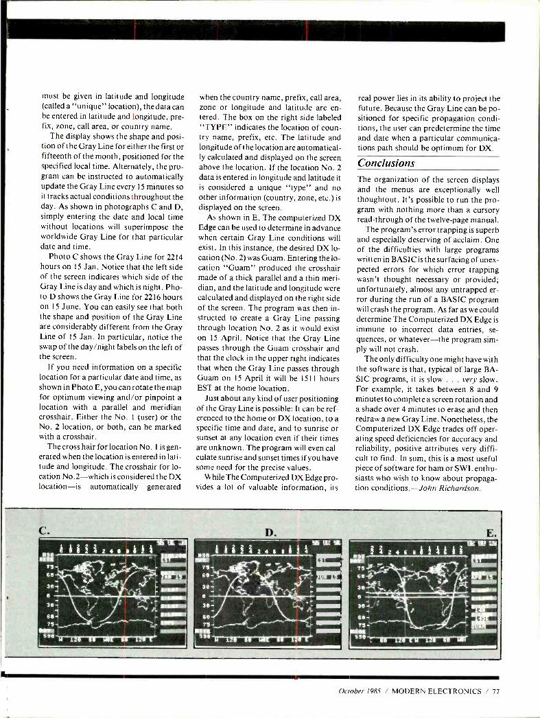
must be given in latitude and longitude (called a "unique" location), the data can be entered in latitude and longitude, pre- fix, zone, call area, or country name.
The display shows the shape and posi- tion of the Gray Line for either the first or fifteenth of the month, positioned for the specified local time. Alternately, the pro- gram can be instructed to automatically update the Gray Line every 15 minutes so it tracks actual conditions throughout the day. As shown in photographs C and D, simply entering the date and local time without locations will superimpose the worldwide Gray Line for that particular date and time.
Photo C shows the Gray Line for 2214 hours on 15 Jan. Notice that the left side of the screen indicates which side of the Gray Line is day and which is night. Pho- to D shows the Gray Line for 2216 hours on 15 June. You can easily see that both the shape and position of the Gray Line are considerably different from the Gray Line of 15 Jan. In particular, notice the swap of the day /night labels on the left of the screen.
If you need information on a specific location for a particular date and time, as shown in Photo E, you can rotate the map for optimum viewing and /or pinpoint a location with a parallel and meridian crosshair. Either the No. 1 (user) or the No. 2 location, or both, can be marked with a crosshair.
The cross hair for location No. 1 is gen- erated when the location is entered in lati- tude and longitude. The crosshair for lo- cation No.2 -which is considered the DX location -is automatically generated
when the country name, prefix, call area, zone or longitude and latitude are en- tered. The box on the right side labeled "TYPE" indicates the location of coun- try name, prefix, etc. The latitude and longitude of the location are automatical- ly calculated and displayed on the screen above the location. If the location No. 2 data is entered in longitude and latitude it is considered a unique "type" and no other information (country, zone, etc.) is displayed on the screen.
As shown in E, The computerized DX Edge can be used to determine in advance when certain Gray Line conditions will exist. In this instance, the desired DX lo- cation (No. 2) was Guam. Entering the lo- cation "Guam" produced the crosshair made of a thick parallel and a thin meri- dian, and the latitude and longitude were calculated and displayed on the right side of the screen. The program was then in- structed to create a Gray Line passing through location No. 2 as it would exist on 15 April. Notice that the Gray Line passes through the Guam crosshair and that the clock in the upper right indicates that when the Gray Line passes through Guam on 15 April it will be 1511 hours EST at the home location.
Just about any kind of user positioning of the Gray Line is possible: It can be ref- erenced to the home or DX location, to a specific time and date, and to sunrise or sunset at any location even if their times are unknown. The program will even cal- culate sunrise and sunset times if you have some need for the precise values.
While The Computerized DX Edge pro- vides a lot of valuable information, its
real power lies in its ability to project the future. Because the Gray Line can be po- sitioned for specific propagation condi- tions, the user can predetermine the time and date when a particular communica- tions path should be optimum for DX.
Conclusions The organization of the screen displays and the menus are exceptionally well thoughtout. It's possible to run the pro- gram with nothing more than a cursory read -through of the twelve -page manual.
The program's error trapping is superb and especially deserving of acclaim. One of the difficulties with large programs written in BASIC is the surfacing of unex- pected errors for which error trapping wasn't thought necessary or provided; unfortunately, almost any untrapped er- ror during the run of a BASIC program will crash the program. As far as we could determine The Computerized DX Edge is immune to incorrect data entries, se- quences, or whatever -the program sim- ply will not crash.
The only difficulty one might have with the software is that, typical of large BA- SIC programs, it is slow ... very slow. For example, it takes between 8 and 9 minutes to complete a screen rotation and a shade over 4 minutes to erase and then redraw a new Gray Line. Nonetheless, the Computerized DX Edge trades off oper- ating speed deficiencies for accuracy and reliability, positive attributes very diffi- cult to find. In sum, this is a most useful piece of software for ham or SWL enthu- siasts who wish to know about propaga- tion conditions. -John Richardson.
C.
i 24 8 8 8 2 i
43-a
36-. : - 3A - - . :.. LIME
se ..- 93 =,,,.-
M
October 1985 / MODERN ELECTRONICS / 77
Will/ill' COMMUNICATIONS /1/lili
Shortwave Station News & Schedule Updates
By Glenn Hauser
Here's a roundup of information to help you get the most out of your short- wave listening and DXing this fall. All
times are UTC. Alaska. KNLS finally gave up trying to
reach Europe this summer on its planned schedule of 1730 -2000 on 7355; a few weeks later it came back to try English at 0500 -0600 on 11960. The other English broadcast, beamed due west instead of due north, was planned to be on 9555 in
September at 0700 -0930 (via Bill Mat- thews, OH).
Australia. ABC's domestic shortwave stations in Perth, Melbourne, Brisbane, and formerly Sydney have been favorite listening for years, and soon they'll have company from three towns in the North- ern Territory, a part of the Outback where shortwave is long overdue as the most efficient way of serving sparsely -set- tled areas. Existing studios in Darwin and Alice Springs will feed three 50 -kW trans- mitters, in Alice Springs, Tennant Creek and Katherine, using the 6 -MHz band in
the day, 2 -MHz mornings and night (moving up to 9 and 3 MHz when the sun- spot count improves), probably making the switch around 0830 and 2230. Target date is before the end of this year (Rodney Norris, Australian DX News).
The Australians also operated Papua New Guinea's domestic shortwave ser- vice before independence. Radio Aus- tralia still provides a surrogate domestic service to PNG (friendly rather than hos- tile like Radio Free Europe /Radio Liber- ty /Radio Marti), in locally- accented "re- gional English" at 0800 -0945 and in Neo- Melanesian (or Pidgin) at 0945 -1100 on 5995, 6080, 9760. Night owls such as Da- vid Alpert in New York enjoy listening to this service for its local flavor but good rock music and complete news, while oth- er Radio Australia frequencies carry its
mainstream service. Meanwhile, PNG is
about to enter the television age. After much debate and considerable opposi- tion, a TV network based in Newcastle,
Australia, has been authorized to provide television to PNG -not including any foreign advertising. On its independence day, September 16, Papua, New Guinea, planned to change its name following a nationwide competition. See what name you hear on R. Australia, or on PGN's main frequencies of 9520 and 4890 kHz. Regional SW stations have been pro- mised power increases from 2 to 10 kW.
Austria. In our August English sched- ule, Radio Austria was misidentified as
"Radio Australia International." Per Austria's mailbag program, it's far from the first time those two countries with very little in common except a similar name, have been confused.
Brazil. The reorganization of the 49 -meter band shown in our June column is scheduled to go into effect October 5 at 0300 (midnight in Brazil), with the fol- lowing additions: 5980 (ex -5975) Ceara Radio Clube, Fortaleza; 6030 (ex -6105)
R. Globo, Rio; 6105 (ex -6030) R. Tupi, Rio; 6160 (ex -5965) R. Pampa, Porto Alegre; 6170 (ex -6165) R. Cultura, Sao Paulo; and 6175 -6195, 250 kW R. Naci- onal, Brasilia (via Antonio R. da Motta and Claudio R. Moraes).
Burkino Faso is the new name of Upper Volta, but at least the remarkably named capitol Ouagadougou has not yet been changed. Once a tough catch on SW, the power on 4815 seems to have been raised. The best time to hear it is 2300 -2400, its fi- nal hour each day after the even -stronger Africa No. 1, Gabon, closes on 4810. Both are mostly in French. Or you can try again from sign -on around 0530 week- days; the signal should be fading out by the later weekend sign -on time of 0700.
Canada. Radio Canada International wants to be heard in the Far East. A west
coast transmitter site would seem to be the answer, but it's not technically or eco- nomically feasible to put one on Vancou- ver Island. So RCI is trying to work out a
deal with some other international broad- caster to build a joint relay station some- where in the Far East. KYOI, Saipan, says it's not for sale, but does plan to sell
two hours of time to RCI each local
morning. RCI is already using existing stations in Hong Kong and Japan to broadcast once a week in English and Ja- panese. You may be able to hear the latter via NSB, Tokyo, Sats. 0830 -0900 on 3925, 6055, 9595. Elizabeth Gray, co- host of As It Happens, won't be back this fall. Despite critical acclaim, she got a
longer vacation than expected last June. Colombia. Minister of Communica-
tions Mrs. Noemi Sanin Posada has warned eleven radio stations to cease broadcasting programs by witches, magi- cians, sorcerers and fortune -tellers, or else; she's also concerned about over-en- thusiastic sports announcers inciting ag- gression and violence. We dearly wish we
could tell you which stations are in- volved. Perhaps the fortune tellers could move to Radio Marti, which broadcasts horoscopes to Cuba.
Cook Islands. Radio Cook Islands is
being heard better in North America now thanks to doubling its power from 500 watts to 1 kilowatt on 11760. Actually, it's always a few hundred Hz on the low
side, so look for a tell -tale heterodyne against 11760.0 stations, while hoping the latter will be weak enough not to block RCI. Depending on interference, you might hear it in the 0100 -0700 period; a good indicator of South Pacific reception quality is Tahiti on 11825.
Cuba. Here's a frequency to watch for action when Cuba's territory is violated: 5765 kHz SSB (variable). Bob Rankin in
Kansas reports in the Ozark Mountain DX Log that a Cuban Frontier Guard Forces net stands by here; he once heard a flurry of contacts during a half -hour period.
Egypt. The clandestine Voice of the Libyan People, mentioned in our Sep- tember column under Sudan, did make a
comeback, this time on 11975 kHz, in
Arabic at 1800 -2000 and 0400 -0600; jam- ming can be heavy.
Gabon. Africa Number One claims to be reaching a huge audience in French of 15 million; now they're thinking about starting an English service. Several of the French -speaking DJs already throw in
brief bits of English, and less than a min-
78 / MODERN ELECTRONICS / October 1985
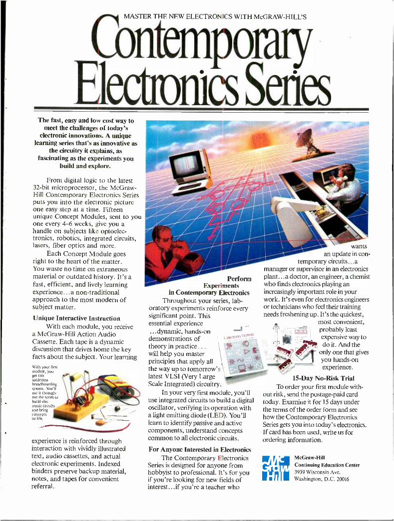
y MASTER THE NEW ELECTRONICS WITH MCGRAW- HILL'S
Contempo Males Series
The fast, easy and low cost way to meet the challenges of today's
electronic innovations. A unique learning series that's as innovative as
the circuitry it explains, as fascinating as the experiments you
build and explore.
From digital logic to the latest 32 -bit microprocessor, the McGraw - Hill Contemporary Electronics Series puts you into the electronic picture one easy step at a time. Fifteen unique Concept Modules, sent to you one every 4-6 weeks, give you a handle on subjects like optoelec- tronics, robotics, integrated circuits, lasers, fiber optics and more.
Each Concept Module goes right to the heart of the matter. You waste no time on extraneous material or outdated history. It's a fast, efficient, and lively learning experience... a non -traditional approach to the most modern of subject matter.
Unique Interactive Instruction With each module, you receive
a McGraw -Hill Action Audio Cassette. Each tape is a dynamic discussion that drives home the key facts about the subject. Your learning With your first module, you get this solderless breadboarding system. You'll use it through- out the series to build elec- tronic circuits
- -- ç and bring
to life.
experience is reinforced through interaction with vividly illustrated text, audio cassettes, and actual electronic experiments. Indexed binders preserve backup material, notes, and tapes for convenient referral.
Perform Experiments
in Contemporary Electronics Throughout your series, lab-
oratory experiments reinforce every significant point. This essential experience ...dynamic, hands -on demonstrations of theory in practice.. .
will help you master principles that apply all the way up to tomorrow's latest VLSI (Very Large Scale Integrated) circuitry.
In your very first module, you'll use integrated circuits to build a digital oscillator, verifying its operation with a light emitting diode (LED). You'll learn to identify passive and active components, understand concepts common to all electronic circuits.
For Anyone Interested in Electronics The Contemporary Electronics
Series is designed for anyone from hobbyist to professional. It's for you if you're looking for new fields of interest...if you're a teacher who
wants an update in con-
temporary circuits...a manager or supervisor in an electronics plant...a doctor, an engineer, a chemist who fords electronics playing an increasingly important role in your work. It's even for electronics engineers or technicians who feel their training needs freshening up. It's the quickest,
most convenient, probably least expensive way to
'7! do it. And the only one that gives
1 you hands -on experience.
15 -Day No -Risk Trial To order your first module with-
out risk, send the postage -paid card today. Examine it for 15 days under the terms of the order form and see how the Contemporary Electronics Series gets you into today's electronics. If card has been used, write us for ordering information.
r McGraw -Hut
Y Continuing Education Center 3939 Wisconsin Ave.
I I ill Washington, D.C. 20016
COMMUNICATIONS ...
ute of news headlines in English has been heard around 1200 and 1500 on 15200. Frequencies to check later in the day are 15475 and 4810, each 500 kilowatts.
Guam. KTWR started testing its new antennas for Australia on 11735 kHz be- fore 0900, per Mick Ogrizek in Australian DX news. A new out -of -band frequency has been authorized for US stations in the Pacific, 12025, used initially by KFBS, Saipan and KTWR, in various languages at various times. We expect the new AWR station will use it too. In SPEEDX- GRAM, Mel Hickman reported this plans to be on by year end with four 100 -kW transmitters, 16 hours per day in
20 languages to the western Pacific and East Asia.
Hungary. Radio Budapest listings in
August should have been bracketed so that all frequencies are used for all broad- casts between 0030 and 0330 (one hour later from late September).
Ireland. Legislation against pirate sta- tions has been pending; a couple to try for if they still exist: Radio Na Gael, 6340 kHz, from 2300 to 0900; Radio Dublin carrying "World Music Radio" (a legal entity in Holland), Sundays 0445 -0900; Mondays 0100 -0515 on 6910. W.M.R. hopes to gain its own transmitter soon on 9845, location unspecified but our guess is Italy.
Israel. Two frequencies in our August list have been adjusted -9435 instead of 9440, and before 2300, 11658 instead of 11655. Broadcasts should already be one hour later now, as Israel sensibly ends DST September 14, earlier than most oth- er countries. The then 1900 and 2130
broadcasts should have been bracketed to show all four frequencies applying to both.
Italy. Yet another private station has been carrying out shortwave tests. Radio Calabria Interantional, with 200 watts on 13630, Sats. & Suns. 1230 -1330. They planned to add a 1 kilowatt unit on 7615,
and two more transmissions on 13630,
0900 -1030 and 2200 -2300. Reports are wanted, and no return postage is neces- sary (Play -DX).
Kenya. Voice of Kenya registered this schedule for tests of its new 250- kilowatt transmitters at Koma Rock: 1230 -1530
and 1930 -2130 on 6050, 7225; 1530 -1930 on 9655 and 11745; 0600 -1600 on 9725
and 9635.
Korea, North. Radio P'yongyang has made several frequency changes for its
110- minute paeans to Kim I1 Sung in En- glish: to the Americas, 2300 on 9715, 9555; 1100 on 9977, 9750 (beware: South Korea also uses 9750); to other areas: 0600 on 12000, 11655, 9360; 0800 on 15340, 15245, 11830, 9765; 1300 on 15340, 11880; 1500 on 11880, 9977, 9625; 1700 on the same; 2000 on 11655, 9350,
6576 (Nagoya DX Circle via Australian DX News).
Korea, South. Radio Korea, in con- trast, makes few frequency changes but periodically changes times. Bill Matthews in Ohio provides the revised schedule of 1 -hour programs: to North America at 0200 on 11810, 15575; 0400 on 9570; 1400
on 9750, 15575. To other areas: 0200 on 7275; 0400 on 11820, 15575; 1100 on 7275, 15575; 1400 on 9570; 1600 on 9870;
1800 on 15575; 2200 on 7550, 6480; and 2300 on 15575. There are also 15- minute English news broadcasts scattered throughout the day on many of the same frequencies.
Mexico. It seems there was no hurry af- ter all to hear Radio Huayacocotla on 2390; Christian Zettl updates his July re-
port with news that for political reasons, the authorities have again denied a medi- umwave frequency to the station. So it's been distributing cheap shortwave con- verters to its listeners.
Mongolia. Radio Ulan Bator made some summer frequency changes, too late for our August listing; whether these will
continue into the fall, or again resemble the listing, is unclear. Try all possibilities to be sure, Mon. -Sat. for 35 minutes at: 1200 on 12015, 9615; 1255 and 1940 on 15305, 9575; 1445 on 12015, 9575 (via Joe Talbot, Alberta).
Pakistan. Add these slow- English news quarter -hours from Radio Pakistan: 0230 on 7315, 15175, 17660; 1100 on 15595,
17660; 1600 on 9885, 11675, 15595, 17660 (via Craig Seager, ADXN).
Philippines. Radio Veritas Asia, run by the Catholic church, broadcast a report in
July that it might have to close down due to lack of funds to pay maintenance costs of some 4 megapesos this year. Its latest English schedule showed 0200 -0225 on 15195, 1500 -1530 on 9570. Among the program titles were: "Explore the Philip- pines" Wed. 0205, "RV Listeners Inter- national" Sat. 0200; "Our Asian Memor- andum," Mon. 1505; "Women of Asis," Sat. 1517 (via Joe Talbot, Alta.). Several announcers at domestic Philippine sta- tions have been gunned down by terror- ists this year.
Puerto Rico. The Voice of America plans to build a major relay facility here, the keystone of its Caribbean network. The San Juan Star reported opposition from some politicians, who felt the U.S. had acted unilaterally without consulting the Puerto Ricans, and there was suspi- cion that the Cabo Rojo site might also be used for m ilitary training, since the Army Corps of Engineers is designing it. But A.C.E. is routinely responsible for build- ing VOA relay stations. Negative impact on tourism is supposed to be negligible, since it's on Bahia Sucia, "dirty bay," where no one wants to go, anyway. There are to be nine 500 kW shortwave, and one 100 kW mediumwave transmitters; 40,000 square feet of buildings, 60 -80 per- sonnel; construction cost is $150 million involving some 200 people between 1988
and 1990 (via David Solliday).
Romania. Radio Bucharest has a pro- gram on the UTC Monday 0400 broad- cast called "Radio Pictures " -we as- sume mental imagery is involved rather than slow -scan TV. Other topics by UTC day: Tue., "From Romania's Experi- ence,"; Wed., "Romania Today & To- morrow"; Thu., "Focus on Topical Questions "; Fri., "Listeners' Letter- box"; Sat., "Home News "; Sun., "Tour- ist News ". Check 11940, 11810, 9570, 9510, 6155, 5990 (via Kraig W. Krist).
Sri Lanka. After spending millions of marks to build a new relay station near
82 / MODERN ELECTRONICS / October 1985
Trincomalee, the Voice of Germany tem- porarily "abandoned" it this summer due to repeated Tamil terrorist attacks on people working at the station, not yet in full operation. Meanwhile, the VOA con- tinues building its new i elay station on an- other part of the island, near Chilaw, to be on the air by 1990 (ADXN). Syria. Despite announcements that it was on 13700, Damascus Radio's 1200 -1300 broadcast in English to North America has been heard on 11625, a frequency really too low this summer, but which should improve in the fall -unless they've changed it again.
Taiwan. Voice of Free China relays by WYFR in Florida on 5985 kHz contain these programs in quarter -hour segments at 0100 -0200 and 0500 -0600 on the UTC day shown; and the next UTC day (more or less) at 0200 -0300. All three move one hour later when DST ends. Daily, News and Comentary first; Let's Learn Chi- nese, last. The middle half: Sun., "Main Roads & Byways," "Mailbag Time "; Mon., "Journey into Chinese Culture," "Countdown "; Tue., "Spectrum ", "Spotlight "; Wed., "Mandarin Kitchen," "Jade Bells & Bamboo Pipes "; Thu., "Chinese Story" "World of Science "; Fri., "Life in ROC," "Chi- nese Music "; Sat., "People at Work," "Taiwan Economic Report ". (via Charles Weiss, OH). There's another broadcast at 0200 on 9680. If you want a greater challenge in hearing VOFC direct, the schedule has changed to: 0200 and 0300 on 15125, 11825, 11745, 9685; 2100 on 11860, 11825, 9765, 9600, 9510; 2200 on 11825, 9600 (via Robert Chester, Aus- tralia).
UKOGBANI. BBC dropped its Ascen- sion relay channel of 21660 this summer, intended for South Africa, but a useful off -the -back source for us in the 1330- 1600 period. Perhaps it'll be back with the southern spring. "The Last Night of the Proms," that cheerful audience- partici- pation concert, will be broadcast live at 1830 Sat., Sept. 14 when 15400, 15070 or 12095 might be audible here; after 2000, 15260 is definite. BBC ended its "Com- puter World" series about the time our
July column came out, but they do plan to revive it later, not necessarily at the same times.
United Nations. UN Radio has relied on VOA transmitters in the US and abroad but now plans to set up its own re- lay network of 250 -kW transmitters in Chile, Ethiopia, Iraq and Thailand -a motley group of countries; perhaps early this Fall, per ITU registrations uncovered by Bob Padula of ADXM.
U.S.A. Shortwave stations never seem to meet their initial target dates, and KVOH, Simi Valley, CA is no exception. As July 4 approached we found out that the debut had been pushed back to Thanksgiving (it seems a holiday is re- quired), due to problems in getting per- mits for the antennas from Ventura County; and the transmitter had not yet arrived. KCBI, Dallas, however, was bus- ily testing this summer to Europe on 11790 intermittently between 1400 and 2100 and in August was to go on R. Earth Sundays at 1800 -2100. WMLK, Bethel, PA, was also testing on 15110 around 1700 -1900, and 15150 at 0400 -0600. WRNO New Orleans changed some fre- quencies to: 2100 -2230 on 11705, 2230 -0100 on 9852.5. NDXE, Alabama, says it's not for sale, progress is slow.
Radio Marti faces a $2.5- million budg- et cut for violating separation between church and state, by broadcasting Catho- lic Mass to Cuba Sunday afternoons.
AFRTS, Los Angeles is useful for car- rying some network programs hard to find on local affiliates. "Newsmark," the now weekly CBS documentary, is sched- uled UTC Sundays 0230 and 0730, but the first time is subject to sports pre -emption, and the repeat is during the 2 -hour break for U.S. transmitters; David Alpert in New York suggests you try an SSB feeder presumably from England on 7572. "Monitoradio" should give us a taste of what the Christian Science Monitor's own shortwave station should be like if and when it goes on the air -AFRTS now carries this on Sundays at 2230, Mondays 0330, again- sports permitting. Pres. Reagan's weekly radio speech and the Democrat response an hour later are
scheduled Sats. 1606 and 1706, unless bumped by sports. We scanned the entire AM dial in South Florida during Rea - gan's talk, and found it carried on only one weak station. (All are one hour later by UTC after DST ends.) Skipper Thur- man in Chicago informs us that AFRTS can be heard not only on its usual short- wave frequencies, but also via satellite - Satcom F -1, transponder 20.
U.S.S.R. Radio Moscow made lots of seasonal frequency changes Sept. 1 for the North American Service at 2200- 0300, now scheduled on the following, not quite all at once: 15425, 15240, 12050, 11770, 11710, 9880, 9765, 9740, 9720, 9640, 9530, 7400, 7320, 7310, 7195, 7175, 7105, 6170. Radio Kiev at 2330 -2400 is on 9685, 11720, 11790, 13605, 15180; 0200- 0230 on 7175, 11720, 11790, 13605, 15180. There'll be more changes Oct. 1 as all these move one hour later (via Kraig W. Krist, Joe Talbot, James E. McDon- ald).
Vietnam. You have until Nov. 30 to en- ter the Voice of Vietnam's essay contest, "What Do You Know About Vietnam ?" which celebrates four different anniver- saries this year including the station's 40th. Listen in or write them for the exact questions. They invite not only written entries, but illustrations. Prizes aren't specified, but there's no mention of trips to the country, the grand prize in the Cuban equivalent.
Yugoslavia. R. Yugoslavia's 500 -kW transmitter project seems to be nearing completion at Bijcljiva, as a tentative fre- quency schedule has been registered. Among those planned for use in our eve- ning are 6100, 7240, 9620, 11805 and 11895.
Zaire. Soon after independence 25
years ago, Kinshasa started an external service in English, but it didn't last very long. Finally, they seem to be doing it
again. Chris Bagge in Massachusetts caught La Voix du Zaire on 15245 with a program in English about the music of Zaire, around 0130 UTC, but we could not immediately confirm this; Italy and Moscow were also on the frequency.
Good listening! hE
October 1985 / MODERN ELECTRONICS / 83
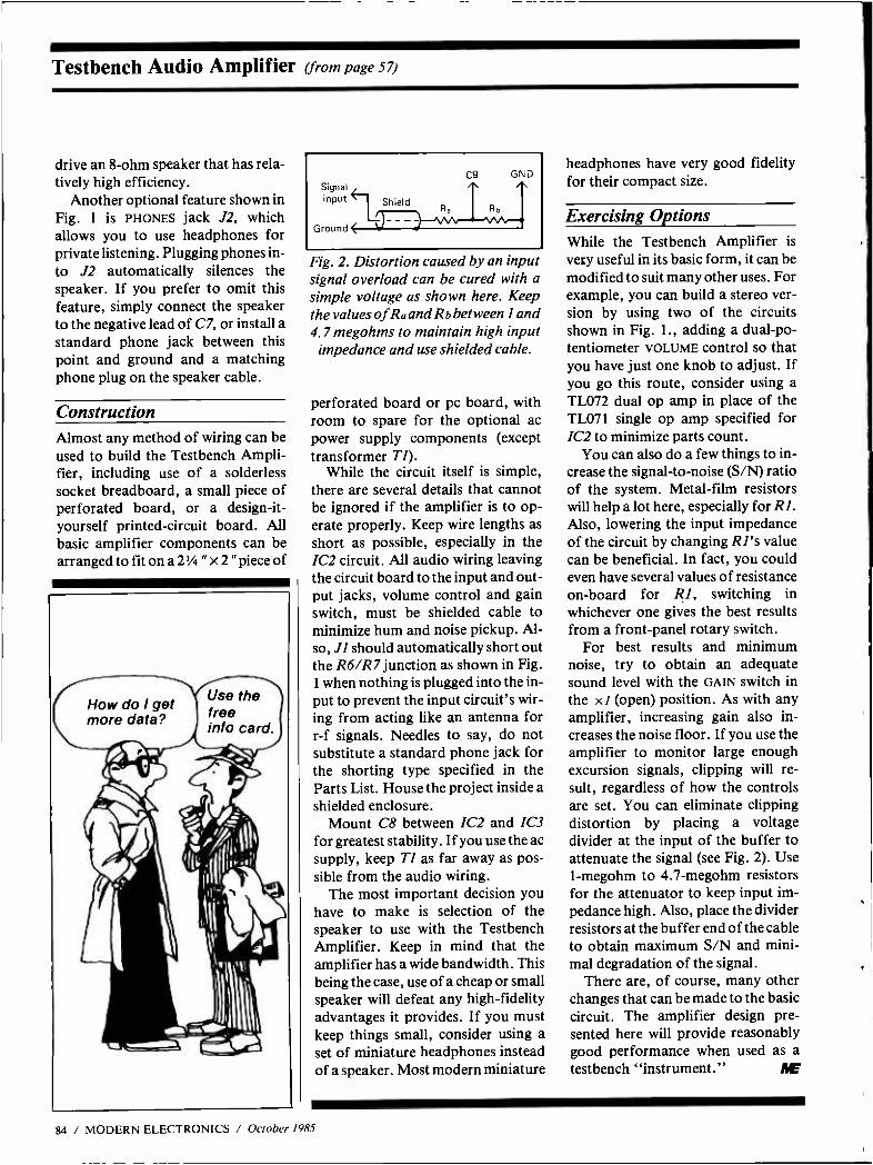
Testbench Audio Amplifier (from page 57)
drive an 8 -ohm speaker that has rela- tively high efficiency.
Another optional feature shown in Fig. 1 is PHONES jack J2, which allows you to use headphones for private listening. Plugging phones in- to J2 automatically silences the speaker. If you prefer to omit this feature, simply connect the speaker to the negative lead of C7, or install a standard phone jack between this point and ground and a matching phone plug on the speaker cable.
Construction Almost any method of wiring can be used to build the Testbench Ampli- fier, including use of a solderless socket breadboard, a small piece of perforated board, or a design -it- yourself printed- circuit board. All basic amplifier components can be arranged to fit on a 2 1/4 " x 2 "piece of
C9 GND Signal /. input Shield
.t
Ra R i,
Ground ( Y
Fig. 2. Distortion caused by an input signal overload can be cured with a simple voltage as shown here. Keep the values of Ra and Rb between 1 and 4.7 megohms to maintain high input
impedance and use shielded cable.
perforated board or pc board, with room to spare for the optional ac power supply components (except transformer TI).
While the circuit itself is simple, there are several details that cannot be ignored if the amplifier is to op- erate properly. Keep wire lengths as short as possible, especially in the 1C2 circuit. All audio wiring leaving the circuit board to the input and out- put jacks, volume control and gain switch, must be shielded cable to minimize hum and noise pickup. Al- so, J1 should automatically short out the R6 /R7 junction as shown in Fig. 1 when nothing is plugged into the in- put to prevent the input circuit's wir- ing from acting like an antenna for r -f signals. Needles to say, do not substitute a standard phone jack for the shorting type specified in the Parts List. House the project inside a shielded enclosure.
Mount C8 between IC2 and IC3 for greatest stability. If you use the ac supply, keep Tl as far away as pos- sible from the audio wiring.
The most important decision you have to make is selection of the speaker to use with the Testbench Amplifier. Keep in mind that the amplifier has a wide bandwidth. This being the case, use of a cheap or small speaker will defeat any high -fidelity advantages it provides. If you must keep things small, consider using a set of miniature headphones instead of a speaker. Most modern miniature
headphones have very good fidelity for their compact size.
Exercising Options While the Testbench Amplifier is
very useful in its basic form, it can be modified to suit many other uses. For example, you can build a stereo ver- sion by using two of the circuits shown in Fig. 1., adding a dual -po- tentiometer VOLUME control so that you have just one knob to adjust. If you go this route, consider using a TL072 dual op amp in place of the TL071 single op amp specified for IC2 to minimize parts count.
You can also do a few things to in- crease the signal -to -noise (S /N) ratio of the system. Metal -film resistors will help a lot here, especially for R1. Also, lowering the input impedance of the circuit by changing RI's value can be beneficial. In fact, you could even have several values of resistance on -board for R1, switching in whichever one gives the best results from a front -panel rotary switch.
For best results and minimum noise, try to obtain an adequate sound level with the GAIN switch in the x 1 (open) position. As with any amplifier, increasing gain also in- creases the noise floor. If you use the amplifier to monitor large enough excursion signals, clipping will re- sult, regardless of how the controls are set. You can eliminate clipping distortion by placing a voltage divider at the input of the buffer to attenuate the signal (see Fig. 2). Use 1- megohm to 4.7- megohm resistors for the attenuator to keep input im- pedance high. Also, place the divider resistors at the buffer end of the cable to obtain maximum S/N and mini- mal degradation of the signal.
There are, of course, many other changes that can be made to the basic circuit. The amplifier design pre- sented here will provide reasonably good performance when used as a
testbench "instrument." AE
84 / MODERN ELECTRONICS / October 1985
WJIII11LBOOKS 1/lili
The latest technical books and lit- erature in the electronics and corn - puter field.
Complete Guide to Modern VCR Trou- bleshooting and Repair by John D. Lenk. (Prentice -Hall, Inc. Hard cover. 332 pages. $27.95.)
Modern VCRs may be enormously complex, but if you use a logical ap- proach, you should be able to trouble- shoot and repair them with the same facil- ity as you do any other audio /video equipment. This is the premise of this lat- est book from a long -time master of servic- ing. Written for the technician who is al- ready familiar with the basics of television and magnetic recording, this book is or- ganized to help him quickly locate the in- formation needed to repair a malfunction- ing VCR, regardless of make or model.
Rather than getting you bogged down with details on a specific make or model, however, the author focuses attention on the circuits and secions that are common to all VCRs. Each is given a separate chapter of its own and is described in full detail, with each point made being illus- trated with drawings and schematic and block diagrams where appropriate.
The opening chapter gives you the ba- sics of Beta and VHS machines, while chapter 2 covers troubleshooting and re- pair procedures for VCRs. All subse- quent chapters are devoted to the com- mon circuits and sections, such as power supplies, remote -control circuits, me- chanical sections, video head configura- tions and so on through audio, video, special features and system control cir- cuits. With the information imparted in these chapters and the manufacturer's service literature, you should have a run- ning start toward repairing just about any videocassette recorder.
Electronics and Microcomputer Circuits by Roger Tokheim. (McGraw -Hill Book Co. Soft cover, 256 pages. $9.95.)
Almost 150 schematic diagrams of use- ful electronic projects you can build are contained in this book, enough to keep you busy for a long time. The circuits en- compass a host of applications ranging from electronic games like digital dice and a slot machine to such practical de- vices for the home as low- and high -tem- perature and burglar alarms to computer game -port interface circuits. There are also a number of circuits for automotive,
camping and outdoor, meter and test in- strument, music /sound -effects, and even timer and thermometer applications. All are arranged by category into 17 distinct chapters for easy lookup. And if you are a newcomer to electronics, there is an ap- pendix that explains the meanings of component symbols used in schematics.
Accompanying each project's sche- matic diagram is an explanation of how the circuit works and a detailed parts list. Where needed, construction hints and test tips are also supplied.
Most of the circuits in this book have appeared in print elsewhere. Hence, they are tried -and -true designs that you can be sure will work the first time out. None re- quire special tools or skills to build, ei- ther, making project assembly a relatively straightforward procedure for even the most complex circuit. If you want to build the circuitry on printed- circuit boards, you'll have to design and fabricate your own since etching- and -drilling guides are not given. You can, however, hand wire on perf board. The Automotive Security System Design Handbook by J. Daniel Gifford. (Tab Books. Soft cover. 227 pages. $12.95.)
Just about everything you need to know about automotive protection sys- tems and devices is covered in this author- itative book. Early on, you are told about thieves and vandals and what motivates them, to give you an idea of what you are up against. You are then given a run- down of the various electronic and non- electronic vehicle security systems cur- rently in use and told about their strengths and weaknesses. Guiding you through the techniques used in effective security system design, device construc- tion and installation, this book covers such diverse topics as tools needed, sen- sors required for just about every applica- tion you can imagine, and modifications that can improve a basic alarm system to make it more effective.
A section on main control boxes dis- cusses these items in general and provides instructions (including schematics) for a main box that you can build to serve as the core of a sophisticated automotive alarm system. Additional circuits illus- trate the add -ons that turn the main box into a complete system. You will find here information on power supplies, power and input conditioning, system controls and sensors, and audible and visible out-
put devices. Assembly and installation in- structions emphasize placement, conceal- ment and safety for both commercial and home -build alarm systems.
This is a helpful book if you want to protect your automotive investment.
NEW LITERATURE Kit & Assembled Products Catalog. A wide variety of kit and assembled elec- tronic products, including the new Per- sonal Loran navigational computer and a 16 -bit portable laptop computer, are showcased in the latest Heathkit catalog. Items listed and fully described in the col- orful 102 -page catalog range from test equipment and ham radio gear to video and hi -fi products to automotive and computer products and much more. All listings are accompanied by full technical specifications and include prices, and most are pictured in photos. For a free copy of the catalog, write to: Heath Co., Dept. 150 -585, Benton Harbor, MI 49022.
Full -Line Instrument Catalog. New audio, video and telephone test instru- ments are featured in B&K- Precision's No. BK -85 full -line catalog. Products are listed according to category for easy look- up. Complete specifications and feature - comparison charts are provided for B &K- Precision oscilloscopes, digital and ana- log multimeters, function generators, multifunction counters, power supplies, capacitance meters, CRT restorer /analy- zers, semiconductor testers, probes and accessories. For a free copy of the Cata- log BK -85, write to: B&K- Precision /Dy- nascan Corp., 6460 W. Cortland St., Chi- cago, IL 60635; Attn.: Advertising Dept. Electronics Bench Tools Catalog. A wide array of tools for the electronics work- bench are listed and described in a new full -color, 10 -page catalog available from OK Industries. The short -form catalog includes complete descriptions and tech- nical information on an array of pneu- matic and hand -held screwdrivers, preci- sion pliers, cutters and crimpers, and pc board holders. Also included are electric minidrills and grinders for prototype work, pc board rework, solder removal, lead -hole cleaning, grinding and polish- ing. For a free copy of the "Bench Tools" catalog, write to: Customer Service, OK Industries, 3455 Conner St., Bronx, NY 10475.
October 1985 / MODERN ELECTRONICS / 85
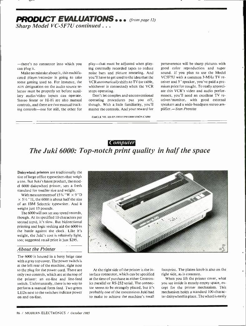
PRODUCT EVALUATIONS (from page 12)
Sharp Model VC -5F7Ú continued .. .
-there's no connector into which you can plug it.
Make no mistake about it, this multifa- ceted player /recorder is going to take some getting used to. For instance, the AUX designation on the audio source se- lector must be properly set before auxil- iary audio /video inputs can operate. Stereo linear or Hi -Fi are also manual controls, and there are two manual track- ing controls -one for still, the other for
play -that must be adjusted when play- ing externally recorded tapes to reduce noise bars and picture smearing. And you'll have to get used to the idea that the VCR automatically shifts to TV (or cable, whichever is connected) when the VCR stops operating.
Don't let complex and unconventional operating procedures put you off, though. With a little familiarity, you'll master the controls. And your reward for
CIRCLE NO. 126 ON FREE INFORMATION CARD
perseverence will be sharp pictures with good color reproduction and super sound. If you plan to use the Model VC5F7U with a common 3 -MHz TV re- ceiver and 3 " speaker, you've paid a pre- mium price for naught. To really appreci- ate this VCR's video and audio perfor- mance, you'll need an excellent TV re- ceiver /monitor, with good external speakers and a wide -bandpass stereo am- plifier. -Stan Prentiss
Computer
The Juki 6000: Top -notch print quality in half the space
Daisywheel printers are traditionally the size of large office typewriters that weigh a ton. But Juki's latest product, the mod- el 6000 daisywheel printer, sets a fresh standard for smaller size and weight.
With measurementsof 153/4 "W x 9 "D x 5'h " H, the 6000 is about half the size of an IBM Selectric typewriter. And it weighs just 13 pounds.
The 6000 will not set any speed records, though. At its specified 10 characters per second (cps), it's slow. But bidirectional printing and logic seeking aid the 6000 in the battle against the clock. Like it's weight, the Juki's cost is relatively light, too; suggested retail price is just $295.
About the Printer The 6000 is housed in a boxy beige case with a gray top cover. The power switch is
at the left rear of the machine, right next to the plug for the power cord. There are only two controls, which are at the top of the printer: an on -line and line -feed switch. Unfortunately, there is no way to perform a manual form feed. Two green LEDs next to the switches indicate power on and on -line.
At the right side of the printer is the in- terface connector, which can be specified at the time of purchase as either Centron- ics parallel or RS -232 serial. The connec- tor seems to be strangely placed, but it's probably one of the concessions Juki had to make to achieve the machine's small
footprint. The platen knob is also on the right side, as is common.
When you lift the printer cover, what you see inside is mostly empty space, ex- cept for the printer mechanism. This mechanism holds a standard 100- charac- ter daisywheel in place. The wheel is easily
86 / MODERN ELECTRONICS / October 1985
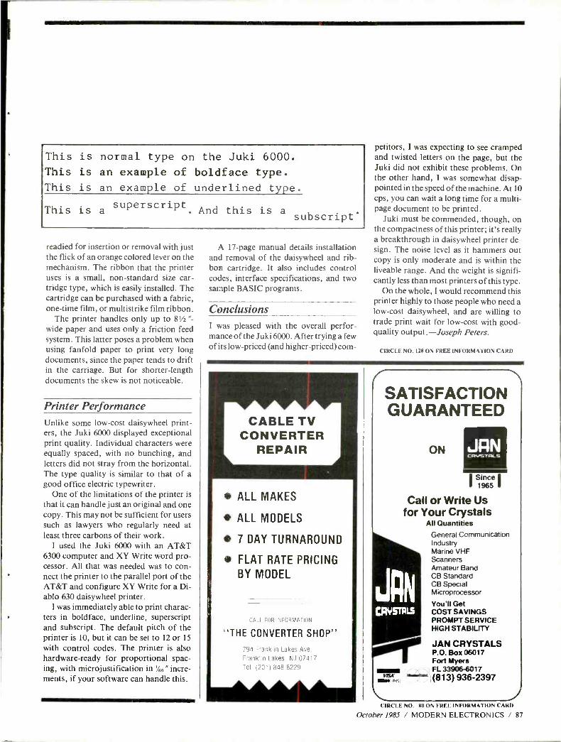
This is normal type on the Juki 6000.
This is an example of boldface type.
This is an example of underlined type.
This is a superscript.
And this is a subscript'
readied for insertion or removal with just the flick of an orange colored lever on the mechanism. The ribbon that the printer uses is a small, non -standard size car- tridge type, which is easily installed. The cartridge can be purchased with a fabric, one -time film, or multistrike film ribbon.
The printer handles only up to 8 % "-
wide paper and uses only a friction feed system. This latter poses a problem when using fanfold paper to print very long documents, since the paper tends to drift in the carriage. But for shorter -length documents the skew is not noticeable.
Printer Performance Unlike some low -cost daisywheel print- ers, the Juki 6000 displayed exceptional print quality. Individual characters were equally spaced, with no bunching, and letters did not stray from the horizontal. The type quality is similar to that of a good office electric typewriter.
One of the limitations of the printer is that it can handle just an original and one copy. This may not be sufficient for users such as lawyers who regularly need at least three carbons of their work.
I used the Juki 6000 with an AT &T 6300 computer and XY Write word pro- cessor. All that was needed was to con- nect the printer to the parallel port of the AT &T and configure XY Write for a Di- ablo 630 daisywheel printer.
I was immediately able to print charac- ters in boldface, underline, superscript and subscript. The default pitch of the printer is 10, but it can be set to 12 or 15
with control codes. The printer is also hardware -ready for proportional spac- ing, with microjustification in %" "incre- ments, if your software can handle this.
A 17 -page manual details installation and removal of the daisywheel and rib- bon cartridge. It also includes control codes, interface specifications, and two sample BASIC programs.
Conclusions I was pleased with the overall perfor- mance of the Juki 6000. After trying a few of its low- priced (and higher -priced) com-
petitors, I was expecting to see cramped and twisted letters on the page, but the Juki did not exhibit these problems. On the other hand, I was somewhat disap- pointed in the speed of the machine. At 10 cps, you can wait a long time for a multi - page document to be printed.
Juki must be commended, though, on the compactness of this printer; it's really a breakthrough in daisywheel printer de- sign. The noise level as it hammers out copy is only moderate and is within the liveable range. And the weight is signifi- cantly less than most printers of this type.
On the whole, I would recommend this printer highly to those people who need a low -cost daisywheel, and are willing to trade print wait for low -cost with good - quality output.- Joseph Peters.
CIRCLE NO. 128 ON FREE INFORMATION CARD
ALL MAKES
ALL MODELS
7 DAY TURNAROUND
FLAT RATE PRICING
BY MODEL
CALL FOR INFORMA IION
"THE CONVERTER SHOP"
794 Franklin Lakes Ave.
Franklin Lakes. NJ 07417 Tel. (201) 848 -8229
SATISFACTION GUARANTEED
ON JAN CRVSTRLS
Call or Write Us for Your Crystals
All Quantities
General Communication Industry Marine VHF Scanners Amateur Band CB Standard CB Special Microprocessor
You'll Get COST SAVINGS PROMPT SERVICE HIGH STABILITY
JAN
v .d..Cod EBY...
JAN CRYSTALS P.O. Box 06017 Fort Myers FL 33906-6017 (813) 936 -2397
CIRCLE NO. 80 ON FREE INFORM .ATION CARD
October 1985 / MODERN ELECTRONICS / 87
Stereo FM That's As Quiet As Mono (Irom page 21)
as a matter of competition, so this new approach doesn't penalize the station in that regard."
"What about reactions of current listeners to WPKT ?" I asked. "Has the station received any compláints from listeners who notice that some- thing has changed ?" Torick told me that at first, when the FMX system used to modulate the 19 kHz stereo pilot carrier as a way to switch on the FMX decoder at the receiving end, that modulation did affect the sound received by listeners to conventional FM stereo sets. "Now, we've changed that and we simply add a subaudible, 10 -Hz signal to provide the switching information and an indicator on the FMX receivers. Since we made that change there hasn't been a single complaint from any listeners to the station. They aren't even aware that the station is using the system experi-
mentally." That speaks well for the compatibility aspect of FMX.
A 25 -Year Old "Mistake" Many audio and FM experts feel that the Federal Communications Corn - mission was short -sighted when they approved the currently used system for FM stereo back in 1961. They provided us (and the rest of the world has since adopted) a transmission system which, while preserving the "status quo" for the mono listener, does not offer the same noise -free re- ception characteristics for the stereo listeners who, today, constitute a clear majority of all FM listeners. At the time of their decision, the idea of using companding for noise reduc- tion was several years off in the fu- ture. (Dolby introduced his famous noise -reduction system for home cas-
t v DESCRAMBLER PARTS
We stock the exact parts and PC Board for Radio
Electronic's February Article on building your own Cable TV Descrambler.
#701 PARTS PACKAGE $29.95 Includes all the original resistors, capacitors, diodes,
transistors, integrated circuits, coils and IF trans- formers (BKAN- K5552AXX).
#702 PC BOARD $12.95 Original etched 8 drilled silk -screened PC Board used
in the article.
#704 AC ADAPTOR $12.95 (14 volts DC @ 285MA)
Both #701 & #702 $39.00
FREE!! Reprint of Radio Electronics Article ON leilïup Your Own Coble TV Deecronbler with
eery purchase.
Add $4.00 Posuga & Handling
TOLL FREE 1- 800 -227 8529 (Orders Only)
1- 617 -339 -5372 (Information)
bW ELECTßOI'IICS,InC.
P.O. Box 800A ® Mansfield, MA 02048 INN
NEW AM STEREO RADIO OWNERS
V Does your new AM Stereo radio only receive Motorola stereo sta- tions?
If so, you're missing the best AM Stereo stations around the coun- try, which broadcast only Kahn/ Hazeltine stereo! (Write for Free station list.)
IITo hear both, add our patented au- tomatic- switching stereo system for $49.95, an easily installed out- board converter. With it, you'll also hear distant stations free of Motorola's "Platform Motion" and "Rain Noise."
Write: Kahn Consumer Products, Inc.
Box 178 Garden City, NY 11530
CIRCLE 30 ON FREE INFORMATION CARD
88 / MODERN ELECTRONICS / October 1985
l OtC1.E 67 ON FREE INFORMATION CARD
sette recorders in 1967 at an Audio Engineering Society Convention in Los Angeles -more than six years af- ter the FCC approval of FM stereo.) Almost twenty years later, when the TV industry was considering how to broadcast stereo over a TV audio channel, the need for companding was realized almost immediately, and the system selected includes a companding approach -in this case one developed by dbx. CBS was one of the proponents for a companding system to be used for stereo TV. Emil Torick tells me that the FMX idea grew out of that related effort.
Since CBS Technology introduced FMX at a professional engineering conference in Chicago last June, the company has been approached by many interested FM broadcasters. Mr. Torick tells me, too, that they've been talking to IC manufacturers who have shown an interest in tooling up appropriate decoder ICs for the FMX system. "You have more than a chicken -and -egg situation here," Torick concluded. "In order to inter- est FM stations in the idea you've got to be able to assure them that there will be receivers out there that can pick up the improved FM stereo sig- nal. And in order to interest receiver manufacturers in building receivers, there has to be a promise of IC avail- ability so that costs don't become prohibitive."
One thing we can all do to encour- age use of this clever system is to make our favorite FM stations aware of its existence. If you tell your favor- ite local FM station managers that there's a way for them to increase their useful stereo listening area by as much as four to one, just watch how fast they'll be picking up the phone to call CBS Technology Center in Stam- ford, Connecticut. In case you are an FM station engineer or manager and want to call, the number is (201) 327 -2000. Ask for Emil Torick or Eu- gene Cooper. Maybe, if we all act on this, we can undo a twenty -five year old mistake after all. AE
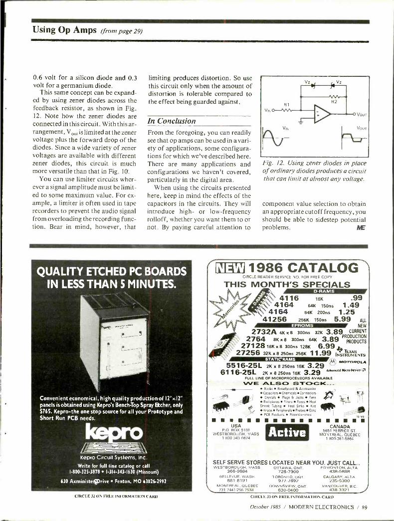
Using Op Amps ( %iorn page 29)
0.6 volt for a silicon diode and 0.3 volt for a germanium diode.
This same concept can be expand- ed by using zener diodes across the feedback resistor, as shown in Fig. 12. Note how the zener diodes are connected in this circuit. With this ar- rangement, Vor is limited at the zener voltage plus the forward drop of the diodes. Since a wide variety of zener voltages are available with different zener diodes, this circuit is much more versatile than that in Fig. 10.
You can use limiter circuits wher- ever a signal amplitude must be limit- ed to some maximum value. For ex- ample, a limiter is often used in tape recorders to prevent the audio signal from overloading the recording func- tion. Bear in mind, however, that
limiting produces distortion. So use this circuit only when the amount of distortion is tolerable compared to the effect being guarded against.
In Conclusion From the foregoing, you can readily see that op amps can be used in a vari- ety of applications, some configura- tions for which we've described here. There are many applications and configurations we haven't covered, particularly in the digital area.
When using the circuits presented here, keep in mind the effects of the capacitors in the circuits. They will introduce high- or low- frequency rolloff, whether you want them to or not. By paying careful attention to
R1
v,
VIN
v
Fig. 12. Using zener diodes in place of ordinary diodes produces a circuit that can limit at almost any voltage.
component value selection to obtain an appropriate cutoff frequency, you should be able to sidestep potential problems. AiE
QUALITY ETCHED PC BOARDS IN LESS THAN 5 MINUTES.
Convenient economical, high quality production of 12 "x 11"
panels is obtained using Kepro's Bench-Top Spray Etcher, only S76S. Kepro -the one stop source for all your Prototype and Short Run PCB needs.
Kepro Circuit Systems, Inc
Write for full line catalog or call 1- 800 -325 -3878 1 -314- 343 -1630 (Missouri)
630 Axministe,Wrive Fenton, MO 63026 -2992
CIRCLE 32 ON FREE INFORMATION CARD
( 01 4'x'11986 CATALOG CIRCLE READER SERVICE NO. FOR FREE COPY
THIS MONTH'S SPECIALS 4116
4164 4164
D-RAMS
16K .99 64K 150ns 1.49
64K 200ns 1.25 41256 256K 150ns 5.99 ALL
NEW
2732A 4K x 8 300ns 32K 3.89 CURRENT
2764 8K x 8 300ns 64K 3.89 PRN PRODUCT
ODUCTIOS
27128 16K x 8 300ns 128K 6.99 27256 32K x 8 250ns 256K 11.99 INS 2UMENTS
5516 -25L 2K x 8 250ns 16K 3.29 M' MOTOROLA
Advanced Micro Device+ 6116 -25L 2K x 8 250ns 16K 3.29 FULL LINE OF MICROPROCESSORS AVAILABLE
WE ALSO STOCK..- Books Breadboard & Accessories Capacitors Chemicals Connectors
-
-9 A Crystals Plugs & Jacks Fans
Enclosures Fuses
., Shrink Tubing Heat Sinks Kits j Knobs Peripherals Probes Opto PCB Products Potentiometers
USA P.O. BOX 9100
WESTBOROUGH, MASS 1- 800 -343 -0874
CANADA 5651 FERRIER ST.
MONTREAL, QUEBEC 1- 800 -361 -5884
Active
SELF SERVE STORES LOCATED NEAR YOU. JUST CALL... WESTBOROUGH, MASS. OTTAWA, ONT. EDMONTON, ALTA.
438 -5888 366 -9684 728 -7900 BELLEVUE, WASH. TORONTO, ONT.
881 -8191 977 -7692 MONTREAL, QUEBEC DOWNSVIEW, ONT. 731- 7441/256 -7538 630 -0400
CALGARY, ALTA. 235 -5300
VANCOUVER, B.C. 438 -3321
CIRCLE 33 ON FREE INFORMATION CARD
October 1985 / MODERN ELECTRONICS / 89
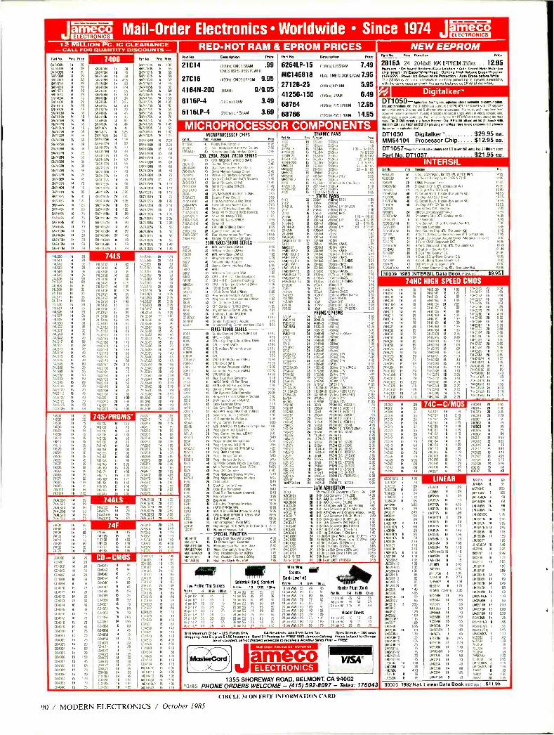
lam Mail -Order Electronics Worldwide Since 1974 lam 1 2 MILL ON PC. IC CLEARANCE - CALL FOR QUANTITY DISCOUNTS - - v . ..n... M . ..v... . ....rio NEW EEPROM
Part Na. Pins Irk°
5514055 SN14o1N 91174029 SN7403N 5574045 557955
5574065 5N7407N 5N7408N 55/409 94741021 5N741151 5X74125 5574135 557419 5574165 5574175 5574255 SN74215 5174226
554742314
91742514
5571265 5N7427N
5674285 51474306
5N74325
5N7433N SN1437N 5N743BN 5574395
5574105 9V7441N
5474425 561744311
SN1441N
9174454 5574465 SN7441N
5974484
5574545 5N7159N
5574605
5574755 5574725 64474734
4
1
4 29 1 35 4 49
1 59 4 59
/ 29
1 35
49 39 49 49 59
9
59 59
69
39
25
59
25 49
79
19
89
45
25
25
69
75
75
75 19
35 39 39
9
7400 5N1414N 55147514 5N7476/1 51747911 5N748á5 557482M 5N793N 55748544 55/486X 56748911 5174909 5574914 511749211
51749361
551404N 5N7195N 5N7a96N
5574978 5x1410pN 5x741055 S5)4102N
55741096 5N7aI16N
5N74121N 5N74122N 5N74123N 5N74125N
547412614 5N741289 5574132N 55741365
55741415 5N74142N
55741435
5N741448
SN74145N
5N74147N
5X7414815
51741501 54741515
517415211
5N14153N
5M4154N
55741555 557415674
5N74157N
1 39 45
1 39 / 495 1 89 / 149 6 55 6 .59 1 39 6 225 1 49
1 79 45 45
89 49 49
1 325 195
1 I 19
39
6 49
9
65
69
á5
9
49 19
59
1 69
6 89
6 395 395 395
65
129
49 9
49
49
99 149
49 59 49
24
11
16
16
21
16
14
16
21
11
16
16
Pari No Pins Price
5N14159N 5414160N 6N74161N 5574162N 5474163N 5N74164N SN74165N SI/74166N SN74167N 5N74170N 55/4121 557417384 5x741745 5N7417Y1
55741761 5x74177N
9474179N 5574I8á1
9N74181N 5x74182N
5x7418451
55741855 5174I9á1
5N14191N
5N74192N
5141419311
5N74194N
5N74195N
51741965
5N14t91N
54741984
58741994
5x742211
5174251N
54742/31 5N74276N
5574219N 94742834
51142615
5N74285N $47436511
55/4369 5N74367N
54743669
5x743991 511743934
95
59
59
6 59
1 59
4 69 8 69
fi 69 I 295 6 I 59
1 4 9s 6 85 6 59
e 59
4 79
1 79
6 149 / 69 / 195 6 105
16 229 16 229 16 69
16 69
16 69
16
65 16 69
I6 49
4 15
11 75
21 11.1
21 115 16
16 71
20 195
n 249 16 b 16
11 29 1e
16 5-
11
16
If a 14
749500 742501 741.502 741603 741.504 741605 741506 741_507
74508 741509 741510 741511 740514 740520 7(521 740526 740527 74528 740530 740532 741537 741535 741542 741517 740551 741573 7(574 74575 745576 7(585 7(586 741590
741597 74593 (5%
7(5107 7415109 7416112 7415122
7415123 7405125 1415126
35
29 39
35 99 99
35
35
35
35
79 35 29 35
39 39 39
35 39 49
ri 39 49 45 39 89 39 55
59 89
39 39 45 49
59 59
1415132 740519 7455138 745138 7425139 7(5145 7415,47 7(548 7415151 7415153 7415154 7415155 7415156 7415157 745158 1415160 7405161 7415167 7405163 7415164 7415165 7405168 7416169 1455110 1(5113 745114 7405115 745181 7405190
7456191 7(5192 7455493 7415194 7415195 7415196 7416497 7415221
7úS241 7415743
65 59 39
1 59
6 59
6 119 e 195 6 179 1 59 6 59
149 69
6 69
6 69 6 59
1 69 6 69 6 69 6 69 1 89 6 89
119 6 1.49
8 119 6 69 6 69
69 2 49
79
89 79
89 69 59
89 89
109 I09
93 10
28
0 I/
14/5244 r 1415215 26 I
1415251 16
14115253 16
7415257 16
7419258 16
1415260 11
1415266 11
7415273 0 )4L5279 16
7425280 11
7425299 11 74L5322 20 395 7415323 20 395 7415347 15 79
7415353 16 109 7415354 20 95 7425365 16 49 7415366 16
7415362 16
7115368 16
7(5373 20
7415374 25 7(5315 16
/425386 11
1425393 4 7425399 11
1(5490 11
7415533 25
7115534 21 7115540 26
/(5541 21
2415610 0 7(5641 n ]4L5644 20
745645 20
1(5670 IB 7415688 811595 811695 811597 811598
20
Ñ 20
20
219 219 219
49 295 149 149 149 7 49
Pon No Description Rice
21C14 120066) CMOS SRAM .99 CMOS USES LESS POWER
27C16 (45a16) CMOS EPROM 9.95
4164N -200 IMAM/ 9/9.95
61 16P -4 (2006) SRAM 3.49
6116LP -4 2006)LPSRAM 3.69
Pan No Descdptlm Price
6264LP-15
MC146818
27128-25
41256-150
68764
68766
05065) L.P. SRAM 7.49
REAL TIME CLOCK & RAM 7.95
12506) EPROM 5.95
(150115) DRAM 6.49
(45065) 21V EPROM 12.95
(3506s) 25V EPROM 14.95
MICROPROCESSOR COMPONENTS
74500 74502 74504 74505 74508 74509 74510 7451 74515 74520 74522 74530 74532 74537 74538 74564 74565 74574 74585 790 745112 745124
35 35 45
45
4 45
39 1 35
1 35 1 35 1 35 1 35
35 4 45
/ 99 4 89 1 9
4 55
6 199 4 55
6 55
6 275
74S /PROMS' 745132
745133 79135 745135 29138 74519 745140 745151 745153 79157 79158 145160 745169 19124 745175 79188' 745191 746195
745196
744500 744102 /441504 74A8506 7441510 7441530
4 59 4 59 4 59
1 59
4 59 1 59
1/ 15
16
11
16
16
1/ 11
II n 16
15
15
16
16
16
16
16
II
74ALS
189 45 89
19 89 89 69 9 99 99 96
229 429
09 I 0 175 149 149 149
19741 745242 745244 745251 745253 745257 145258 145273 745280 745281' 745288' 745299 745373 745374 245387' 745411' 745472 74&4,3' 745570' 145511' 79512' 145573'
20
n
195 219 219
15 99 16 99 16 99 15 99 20 239
89 16 179 16 179 n 595 0 249 n 249 16 195 n 495 n 4.95 21 195 16 295 11 295 11 /95 11 195
MICROPROCESSOR CHIPS M Mo Pins ream
03247 20 a:.
7955501 40 S.
Z80. ZEDA. Z808. Z8000 SERIES 20 10
280-01C 2e
299 DART 40 :e,
74/1632 II 65 2441574 II 79 7448510 16 79
74415112 4 69
7445138 16 125 744529 a 2.25 74415241 20 225 7445245 0 259 74415373 0 259 74415314 0 2.59
74100 /4F02 74F04 14608 ]4F10 7920 74132 74174
1 69 4 75
1 89 4 75
1 75
4 69 1 79
4 85
74186 II 115 7010 16 95 741138 16 169 14F19 16 149 79157 16 I 59 741158 16 169
741240 741244 741253 741257 741280 741373 79314 74F179
20 375 20 ' 49
IB 79
11 179 11 69 20 489 20 4.59
I6 199
04100 00401 00402 0400
0400 004009 004010 004011
0912 CÁ4013
00914 0915 0916 04011 004018 004019
0920 054021 04022 04023 00924 C04025
074026
04027 04028 004029 051030
mm 0109
1 29 NNI1rIlÌlll / 29
4 29
/ 89
/ 29
6 89
6 59
6 49
4 29
4 29
4 39
1 89
6 39
4 49
6 79
6 79
6 49
6 75
6 75
6 75
29
0 0 59 45
69
9 119
i9
6 75
004041
004042
004043
C04044
C01046
054047
C04048 04049 006050
00951 0952 004053 04056 04059 04060 004066
01068 001069 004010 0311071
004077 Cá4073 004075 004076 004011 004018 004041 004093 0134204 074098 004093
11
16
11
16
16
11
16
16
I6 16
16
16
16
21
IS
11
11
II
11
11
4 4 II II
11
4 11
11
15
14
16
69
79
69
79
89
89
59
39
39
0 79
295 3% 89
45
339
89 9
35
29 49
95 195 10
009003 004503 0450 C04507 004508 004510 06511 C04512 04514 04505 004516 04518 04519 04520 004522 004525 004528 04529 C04531
004538 0191511
C04513 0D6553 0114565
014583 131345131
004585 C04723 CA1224 04011110 1A01441 MC14112 MC14433 4C1449pP MC14572
6
6
6
149 69
129 19
95
85 85
BS 149 49
89
59 0
169 119 I'9 I 69
9 149 149
19
6 495 6 295
5 249 / 59
6 139
6 119 6 9
6 695 4 1195
6 795 1 1795
6 1 95
6 119
a'DMA PIO
5450 A 5101 110,7
s . 059
n013AR1
P10
9 Sew PO 1601 and R.05 Bonded° 9 Sena; 10 00x2101481 9 Se11a100 rlxk5 SNNCI%
46 Se.M 1m
9 CP1148538800411710 -1145110
21 Munter Timer Good 9 91141 Asmorro4us Pee grans 10 Deed Memo Access Caere 40 1%9% PO Interlace Convener 9 5e.1151 11.08 and 5.408 Bonded, 40
44 %Tr%%
(Lacks 77490 0 ¡Lacks SYNCBI
9 Sera' 10 10 CO 0453880N 616407 28 Counter qme Cocci 9 Oua1 Aswcnrolmus Per. mans 40 Parallel PO in edece Controller
1695 95
144 95
275 349 895
1249 295
1149 1149 1149 119
295 395 995
1295 395
1195 1195 1195
95 8 95
1195 1995 095
6500/6800/68606 SERIES 9 MO Mm Oak 1114111. 495 9 MO with CM& 124H4I 525 9 MPU wnh Cock 1315101 795 40 Verrone., Inter Adapter 275 9 Ve1441,9 Oler Adapter 4 95
25 A511c Comm 115114ce Ada0l 695 40 11%1 2 95
9 MPU wan Clock and HAM 595 9 CPI - 8.54 601COp Oscolla,so 695 9 026 - 8 61 rEMen3 C1aan91. 849 9 CPU - 8.61 da C54111812M41 149 24 12848 Sum RAM 2.75
24 128.6 5105 RAM r285141 595 M Perioherai i1le Adapt rf064001 275 40 Rnpneral met Master 1241171 4 95
9 CRT Coned% URIC° 995 65845 9 161 Control f061012564 1495 6850 24 Asynchronous Comm Adapter 295 6860 24 0640055 019114154005M 695 6805518 M MPR 15.04 18010 1995 684886 40 Greta, Purpose lnt Adapter 995 65661 28 Enhanced Rog Comm Interlace 126611 895
8000/80000 SERIES 9 Comm, %en1ed 08w11448110 1295
W CPU-So Chip 8-B3112805 RAMI 495 40 CPU - Ban HM05 1295 40 CPU w1Bas2 Mao Intense% 2995
.1A 40 CO 395 40 CPU 395
033 9 CHI 8.615-Chanee15M9n 1095 ^/ 1 9 CAI 16605.611 1995
9 A hire% Processor 155161 190 0.7 2 9 6le146 Processor 18516111 1250
6088 9 0%18116911 1495
8116 18 Dual Baud Rate Generator 949 4155 9 HM05 RAM 1 0 Hlnnme 495
8156 9 R0M 11' n nm 595 8202 9 1995
8203 40 dkr 2995 8205 16 H .1r 5555421 3.95
8222 24 -1015 225 8224 26 315 8238 20 +54281 395 8231 -5 20 n m 051515 1495
8243 n I,Ol -11Hí 495 8243 84 C ", 995 225013 9 Alms Con 995 8250 26 Roo 1113M PI nage Commune) 1025
8251 26 oO Cann .:.II 325 8253- 24 Nog Cdnm USAgII 349 8254 24 Rog Inlets, 349
6254 24 Prp9ramman -.1 9me1 1399
8255 40 Rog Rrrpher411i. .EPII 425
8257 9 Rog DMA Control.,
5MN1 425 19 8259 9 mpg 0611 595 8259 21 Rog. INC, rod Contrer 695 8272 0 054 MeD
MOM, 695
8272 9 Damn/ F1044 Onk Cent 14.95 8275 9 CR7 4 Cart 172011 1495 8275 40 Rog 5510MVdb 1549
8219 40 Rog IreyboaIOONIIry mte5ace 545
8282 9 %09 rd'OSpW lnlerace 6.45 8282 0 Gene 549 8284 20 0116411M scerve1 549 8287 20 Octal Bus ira6ceive 649 8288 20
Compiler Transceiver Mvenedl 645
8288 20 Bus 2495 8741 20 Bus Artier 19.95 8741 9 0640 LEP MPU Inleraæ 1995 8748 9 55105 EPROM 19.W 95
8249 9 4PR 5461 (EPROM MMS 12d 0491 2995 8755 9 CO w14Kx8 EPROM 6 128.8 MM. 2995 8115 9 EPRá4 1995
0188 0 W9n In19rx1116 14Án 4995 020 41
Numeric 16610%1 IB 811 We 8451 9500
800] 9 Hument Rppmssw En 1950 SPECIAL FUNCTION
MC3470P 11 Floppy 344 Pend Amp Syadn. 495 5151532174 16 N Campa Sync Generator 995 515816/49 24 Mcropracssw Real Terre Mock 895 51456149 16 Micro. Compa4k Ome Clock 695 4445359449 1 Rog 055110141101415e1 160111 1 79 4453691ST 8 Roo. OsSeaAIIDiedel 11081l 195
Cr rr 21 Real -Rate Clock %us RAM 195
PM No.
1021
41155.15
641.150 4169300 4145261 41.4262 4115270 6115280 51452963 8118 11256.150 41256200
2
Pm, DYNAMIC RAMS
4096r 12wns 16 16384.1 1150ns 16 1638141 121011 16 16364.1 1150m 11 65536.1 1150ns II 65.536.1 0305,4 1e 024.1 1300ns
22 2046.1 136511 11 4096.1 025551
22 4096.1 12004 11 8192x1 200ns
2101 210 21031. 2112 1
21 2n4X 2191 21193 2114X--2L 2147HN 21481141 16154045 51544141 45 5101 1015257 HM6116P2 HM6116LP2 1M6116P3 4M61168P3 5461161,4 15611fi8P4 4M6264%12 1111626419-12 HM62610.15 HM6264LP-15 218500
748921 79930 745189 745289
82510 82525
111 6.4x 1)
I125515
15 262.144x112
0
16 1316TO7A2Tii1
n 25644 16 102111 11 102441 11 25614 16 25644 le 102414 14 102444 4 102411 15 10444 N 4095,1 16 102414 18 1024,4 20 102444 n 25641 II 009611 i/ 20188 24 204848 24 204848 21 204858 21 2048,13 21 29488 n 819218 28 819283 21 8192.8 21 81928
6 25641 e 1644 6 256.4 1 102441 6 1644 6 1644
e 102411
7024 78452516 16152532 761552564 2708
1452716 271
27016 27161
2146(4,5 2732 2732/310 2132/375 2732(45
27032(30 215430 276425 2764(25 276445
2Ì 8-25 27128425 2725535 68764
644100 745287 145288 145387 245471 745472 715473 745474 745475 745476 745478 145570 745571 745572 715573 22523 825115 825123 825126 1125129 825130 825165 825191 04875181N
2107
16,49
9 1.39 - 01695
698549 122-911095
I II-9N95 35-8'195 35-85195
39s 95 .5V 010 Ik41
595
01 195
11250n5Ì L P 1915021 14 ( 9 14501518111 249 1455151 M05. 249 145011. 129 - 879.95 1450ns1 L P I 65 - 811295 120011. I 39 - 8/1095
204111LP 189 -8I134 9
Ij<C504QS1s1.
.
.
-
395
I45áasiCMOS 295
Ìt250r05i 01405 <95
1125Ónsj CI.Ptp5 815 3 95
1200111 C 3 9 Ì 1 120151 C LP CMOS
) i5 112551 LP 01405. 795 15OI51CMOS. 695 115061 L
1 LP P CMOS. 7 49
j50nsI 3101 225 5.95
1350nsjCf 165181 2 95
135413101 2.95
15404100 .1934151 395 1551 510.0. (745289) 2.25
PROMS /EPROMS 4 2568 110s)
4
2048.8 1450ns1 409658 145011) -
t 819246 II450n51.
4 102148 145041 / 20940 401113 voltage
2048.8 455u1 204840 CMOS 2018.0 1350551 204858 f550941 403648 1155111.
409648 12001a1 21V. 409648 12501161 201
409658 152,,e, 21 V
409658 13001S1 21V 819218 120%51 21V
10/4051
819248 1250ns121V 81928 125019112.55
21
2/ 2/ 24
21
74
21
21
28 21 21
29
28 2e a 21
16
16
16
16
20
20
20
000B01 4000003
4000801 (%0008 0091309
AA 16
020080 OAC0807 0000808 OAC030
0401 00 0 040100 0061022 0551222 OAC1230 O 401231 AY-3-1015D AY65-1013A
39' 5
549 1095
395 795 395 995 495 375 425 995 595 449
1195 2295
895
595 819248 455741210 .495 859248 ÇM021V 1195 16.6448 125505 128Ì(11V .595 6.36148 125061128512 55 195
3176848 12505 25E5114V1. 1195 819248 1450541 215 1295
32:fi 8 á3R'J64'óc 116730-1) 14 95
25644 FROM T5.16301.11 179 3248 PROM 05 7633111. 179 25611 PROM 0C16306U 195 25648 PROM 15. 1630911. 4 95 5128 PROM 75.63491 495 512.8 PROM OC.1163911 495 51248 PROM 75 105347529651 495 51248 PROM O.C. 16391. 495 102444 PROM TS. 6.95 0448 PROM TS 995
512,4 PROM D6.Ifi051. 295 51244 %0M TS 1631361 .. 295 10414 PROM OC II035511 495 I02444 PROM TS 18151211 . 495 324 PROM 51240 PR084 105 12 5151). 995 328 POMI 75 12751911 . 295 25644 89014 00 0275201
- 295
25614 PROM TS 1275211 . 295 51244 PROM 06. 27511 395
204959 18041 0ai5
1495 102418 PROM TS 18251811. 995
DATA ACQUISITNNI Mos kk 440 Convener .5510 -8V 2.95
0 8 -6I Á1D Commie' (1141501. 1495 26 661 AN Convene ' 1521541. 495 0 851 A/0 Converte' 1111551 349 21 091 AM Cone w/8-Channel Analog 995 28 8434 A/0 nr M 8 -615'0 CCoomew/1161- Cñennel Analog 14.95 9 S-84 AID Convene' 11805. 01k .I. 949 16 8 -M101Á Convene 1078 % Lin l
195 16 8011 214 Convener 1401408-71 149 16 8-8a 0A Converter (401400-81 225 20 8 -Be UUUpIp 01A Conn 105%019 595
4.49 201
8-84 A D/A Cow
Cony Malo 10% Lin
Comp-405N 795
18 101 0íA Cons 100%01¡11 (O;XNhI
595 104311 WA Cons Km
11 12 -134 0/4 Coat (0.2055 Lin )... 695 20 02-4 Cm 4 Up DIA C 1.05% Le.). 0495 n 12.84 Up DIA Cony 110% Lin.) 1395 9 255 Baud DART 425 40 301 Baud 0401 (091602).. 395
Port No. Pins Fun.ti
2816A 24 2048x8 16K E2PROM 350ns. . . 12.95 Features: On-board Address/Data Latches MloTim.d Byte Write ton chip timer) 55 55_43mNe /Beal Optional Nigh Voltage Erase/Program (121Á22V) ' Power Up /Down Wirt Protection 0080 Erase before write The 2816A is an ideal nonvolatile memory 7105Oing in- system alter /5%11N
0116 the same ease and with the same tealures as 28.48 514114 RAM%
Digitalker'° DT1050- 6NbaYM:,w..,w -. d....6..etM1 hemp 0.4.101414 lis. The 011050 Is a sanetard 01GRALIER kit encoded wM 137 separate
e useful words. 2 toms. ana 5 dINerenl Mere r:e durations. The sods and Iodes have neer.
assigned Imerele addresses. neking 17 passible lo ou1101 sr1de words or words corner II lrv:
into phrases 50 e v e n sentences The "w1æ' oul54I d me DT IS',:.. n nienrl ,,nn i;i .e. mar
1 164 911651 math d e Spat P111663111 roe. MM54164 110 merl and Al 121 001111 AIMS
11e21618851 and Ma521042P02 VI Pal One AN r gager 011 he 05 I re0ommenle0 "hem. flea MY 4.4.6 Pen
DT1050 Digitalker'M $29.95 ea. MM54104 Processor Chip $12.95 ea.
DT1057 -6MaM r 66950 aras., hen 137 h we s66 aIs III 2 5014s 114 specs
Part do. áT1057 . $21.95 ea.
M Y.
102020 502030 0151%
065EV5Y 105191 106E55151
01070 0/EV101 160%
20515 205055151 20á'.5P6 206CEV5Kd 207ÁI19 n1A551o1 211170
21TMIH 215105 215EV91 216401 21611%
17111
21751% 224111
226415 /Ki1
Perce
10 4 051100 Osplay M 72111611 6 72119901
9 3110114 7106 8 7116.
2A CMOS Reclson l0 DSptay
m ger M
0 Stopwml0n 0614. 73 0449400 Nnl a 3'v Dam A1O110 Om) 9 1C. 0115911 Ward. Display (Evaluation 00 9 3'x 594 Am (LED Cure) 9 IC Croat Board. 0540411E1NUalmn 150
9 l': 019rI Al0 L0 OS. HID l Bantry Vo11 InUaakr.
21 Cav MOS l0 Skpwal h?imer. 24 Stopwatch Cn1D. I1l IEVeluaon Kill 16 lore Generator.. I4 1MP Generale Chro. 41L 14,114411o11611
II 954r11414 Cemplle I1 O4 Counter D4. ÁTB IE1rMUd4511511
w4 Pot LCD
Wpay 0ecad6lwr Mcropmc 008574411
24 4 Funs DM SnpwOh OCT
21 1 Fmc Stopwatch Cho. KLB IEwlua4n MO
28 8 Or911 Unw Counter 0A. ZS 8 01911 Free. 044411100
28 4 D1g'ILED Up/Down C4r]nkrCA 28 4 D91t LED Up/Down Conner C C
9 lCD 4't C'g11 Up Counter 0a, 10 5 F nation Counter Cho KR IEw14a1
130009 1983 INTERSIL Data Book 1356.. . ...69.95 11
1495 1495
1495 1995 1049 995 10.55
4695 1095 2.25
1495 1695 495 795
595 849 795 895
1595 1949 3149 2149 1095 995
1095 9995
745000 744302 741003 748004 7410104 74100 744010 745011 140014 744020 741027 745030 741032 749532 744051 745058 741073 745074
745075 /411015 745685 741086 790107 /4X0109 7446112 790123 74140125 74110132 74110137 7446138
74HC HIGH SPEED CMOS 59 59 89
59
59 59 69
89 59
79 1.9
89 89
g 99 79
169 75
79 79
229 175 129 159 119
Low Pr6file piel Sockets
M M4. I9 160 10sp
8 on LP 16 14 13
4 %n LP 1 IS 14
I6pmLP 19 1 16
18 pm LP 25 24 23 0 on LP 30 27 25 22 on LP 31 28 26 24 on LP 33 30 28 28 wnLP 40 37 35 40 on LP 49 46 43
501921101IG61dI Standard
PM No 19 1098 1065
8515G 39 35 29 14 DO 0 49 45 .39 16 on 55 55 49 45
18do0 65 59 51
20 on S6 15 65 59 22 pin 5G 79 69 65
24 on 56 79 69 55 28 pin 0 .95 85 75
364110 125 115 99
40511% 1.39 125 115
Ore Wnp ¡jilt Sackett
Saldi Intl 4i3
PM Y. 19 100 100q on WW 55 49
10 on W.4 69 65 14pn1VSV 75 0 16 on WV/ 79 72 18 p1 WV4 95 85 0 on 1V15 1.19 109 22 on WV/ 129 I.19 24 pm VAN 1.35 1.19
28 on WYI 169 1.55
36 pin W441.89 I 79 9pin221/4 229 195
45 59
65 65 75 95
105 109 139 169 179
Nader Pillo RANI P441114. 14 100 18640
14 on HP 65 59 55
16 on HP 69 65 59
24 on HP 1 15 99 89
Healer C4MerS
14pn5C 15 13
16 pin HC .19 17
24 pin 0 29 25
12
15 22
010 hipping: Add 5%plus 911..50 Insurance Send SI
CA Residents: Add (1,Be Postage for FREE 1985 Jamee00Tax Catalog Pr
Spec Subject to Change
Send stamped, se0.addressed envelope to receive a MonMly Sales Flyer - FREE'
(Masté arel
Merl Order Elerlroni4sWOrldwr0e
lameco ELECTRONICS
VISA'
1355 SHOREWAY ROAD. BELMONT, CA 94002 10185 PHONE ORDERS WELCOME - (415) 592 -8097 - Telex: 176043
74000 7402 74C04 74('ÁB 74010 7914 74020 74030 74032 740042
799 7973 19/4
/4085 74086 /4089 74090 74093 /4095
29 35 35 35 35 59
35 35
39 I.19 179 69 59
I.39 29
595
109 119
D5002655 11071CP 11012CP 1107401 1
7198101,
110820P 1LO8/CN 1
11410911
115301024 101029 15309 143055 14430114 e
1IA306CN 1
LM3(BI( 1.4310021 1
0431155 6
043121 1513171
143115 1.64319351 1
1.513141 I/
003065 143201412
43204415 4320424
14432015 5320512 0320T-15 11320524 M322N II 432314 M324N I/ 432902
06433114 5
1043342
1M3352 LM3362 1M337MIP 1613371 0233811 LM339N 11
19134065 L543/á412 554340415 143416124 114391.5 1ÁO401-12 LM3t0T15 LM1340T24 LF341N 11
LA1348N 11
1613505 1135111 A
LF353N 1
7450139 6 1.05
7450147 6 1.29
7450151 5 .9 7440153 6 10 7441C154 / 265 74110157 6 99 74110158 5 99 745010 5 139 74140161 6 19 7410152 6 139 74X0163 6 139 1410164 1 1.35
740165 6 215 7411C166 6 2.49 740173 6 129 14110174 6 109 7400175 6 1.0 74110190 1 159 190191 5 159 7450192 5 149 790193 6 149 1480194 1 119 14110195 6 119 741C221 8 2.95 14140237 e 1/9 7411029 20 2.29 74110241 21 229 7480242 I/ 2.15 74410243 II 2.1S 7480244 26 229
rLLIIIauD1Ny 740107 11 79
740151 16 219 740154 24 325 140157 11 1.75
79160 16 119 79161 16 119 19162 16 119 79163 16 1 19
19164 11 129 710165 16 1 29 79173 II 89 140174 I6 I19 740175 16 I.19 79192 18 139 79193 IB 139 79195 11 1.29
740221 16 115
14110245 74110251 15 74110253 4 1450257 16
7440259 16
7450266 11
7450273 20
29C280 I/ 74110299 0
7440366 2410367 1410373 20
7480374 20
16
10
7410390 74110393 74110533
1410534 14110595 16
16
11
m
74104024 11
141101040 16
7450449 16
7901050 16
741104069 16
741104075 11
74104078 11
71110451 16
7904514 21
7904538 15
74N0Á54w f,
2
I 69 89
2.79 459 559 2 59
259 269 269 159
59 269 2.59 319 3.59 I 5
149 89
59 0
59 195
4.19 259 3.15
195 MUM J9
109 195 59
119 1.95
595 9
2 49
95 .99 69
0 1.25 .59
s9 2.19 119 349 159 135 135 1.35 135 9 85 85
05 e5
149 495
59
65 395 1.19
129 1.09
1.15 189 595
135 135 135 135
75 75 75 75
149
04 29
59 0
740240 740244 140113 740374 740901 140902 140903 740906 740907 740911 740912 710915 740917 19922 141.923 140925 740926 8095 007
ñ
0 II
11
II
II
195 I 95
129 229 59 29 59
59
II B9
28 895 28 895 11 1.19
n 895 IA 449 20 495 16 595 IS 595 11 69 16 69
LAC747X 14
1474814 e LF3551 I.0
11416650 10 1411565 e 0
LM1458014 1
14148811 11
L11489N 11
1011960 II
14160504
8511671N 11
14187214 II 14181784-911 1.418894 16
14189651 14
LA92002T
üN200DA 16
00220 16
NIY2207 11
%R220B 16
%N2211 N 1A2877P
'0M2878P
1429011 11
LM2902N II
1.4290711 I/ 1M0291N 1
1M39006 II
1830504 1
1109097 /
LM3919 18
1839155 11
1039165 11
7C413614 I/
10415159 1
HC4193NB 1
PC195TN 1p2504 I 425532 8
NE5534 1 7&1155 ]86124 791054 795105.45 ICL8038 11
LF3555 1835884
1613594 I
11437661 I
153135 I
1113771 1
1M300N 1M380N I
043815 I
1553825 I
1.543804 1
15130553 5613879
153096 I
LM139tN-01
1539211
14139315
1139851
LM399N
LF41255 n494CN I
T1490P
179 495 495 1.95
10 89
179 I49 I 95
179
1.19
119
59 45
395 595 195 219 159
NE531V 1.79
NE54011 IC5401t 295
NE5401 11 195
NE5504 14 1.95
NE555V 1 35
KRL555 8 0 15455611 I/ 79
NE5585 I6 159 NE5645 16 195
01456524 II 99
1M566C11 8 149
L45675 I .99
11551314 10 295 105711 16 249 4E5926 II 1.19
04103C4 1 1.49
191/155 4 69
1917194 II 79 0617235 II 49 LM13p8á4 I
L473311 14 0 1M13fi00N 16
1411394 II 195 1547T 1 99 76472 11 195
06174155 1 .9 76411 0 3.95
69 59
995 1.95
59
0 69
99 995
2.95
325 295 195
159 095
149 395 249 1.79
295 1.95
295 79
89
249 195
59
1.19
89 2.39
239 239
I 25 195
I 95 595 149 169 139
39
9 59
129 395 119 119
30003 1982 Nat. Linear Data Book 1952 pgs 1 .611.95
CIRCLE 34 ON FREE INFORMATION CARD
90 / MODERN ELECTRONICS / October 1985
jE Mail-Ord Commodore" Accessories
er Electronics Worldwide Since 1974 Jam * * * e * APPLE' Accessories * * * * IBM" Accessories
RS232 Adapter for VIC -20 and Commodore 64
The JE232CM allows connection of standard serial RS232 printers, modems, etc. to your VIC -20 and C -64. A 4 -pole switch allows the inversion of the 4 control lines. Com- plete installation and operation instructions included.
Plugs into User Port Provides Standard RS232 signal levels Uses 6 signals (Transmit, Receive, Clear to Send, Request to Send, Data Terminal Ready, Data Set Ready).
JE232CM $39.95
VOICE SYNTHESIZER FOR COMMODORE VIC -20 AND C -64
Plug -In - Talking in Minutes! JE520CM $99.95
TRS -80 Accessories MPI 51/4" DISK DRIVE
Use asa second disk drive Single - sided Single /double density Full- height drive 48 114 Documentation included Weight'. 17 lbs.
MPI51S $89.95
EXPAND TRS -80 MEMORY TRS -80 MODEL 1,111
Each Kit comes complete with eight MM52901UPO416/4116116K Dynamic RAMS and documentation for conversion. Model 1 16K equipped with Ex- panoon Interlace can be expanded to 48K with 2 Kits. Model SI Can be expanded from 16K to 48K using 2 Kits. Each Ki will expand computer by
TRS -16K3 200ns (Model Ill) $6.29 TRS -16K4 250ns (Model 1) $5.49
TRS -80 COLOR AND COLOR II Easy to Install Kit comes complete with 8 each 41641.20 1200ns) 64K Dynamic RAMS and documentation for conversion Converts TRS -80 Color Computers win D. E. ET, F and NC circuit boards to 32K Also consens TRS -80 Color Computer II to 64K. Flex DOS or OS -9 required to utilize full 64K RAM on all computers TRS-64K-2 $11.95
Update! TRS -80 MODEL IV, 4P Update! Easy to install Kits come complete with TAS -640 -218 ea 4164N- 201200ns) 64K Dynamic RAMs), TRS -64K -2PAL 18 ea 4164's plus PAL chip) and docu- mentation for conversion
TRS -64K-2 expands Model IV from 16K -64K or Model In a OP Porn 6414-12se Iw/Mem. Disks $11.95
TRS- 64K -2PAL Expands Model w (v/Black a wnne Monitors only) from 64K to 128K $29.95
TRS -80 Model 100 NEC Olivetti Easy to install module plugs right into the socket incremens memory in BK increments Complete with module and documentation for inslallatmn
M1008K (T11S40 MOde1100Expepebn1 $39.95 ea. or 3 for $99.95
NEC8KR (NEC PC -8201A a Olivetti At 10 $39.95 ea. or 3 for $99.95
NEW! NEW! TANDY 200 NEW! NEW! NEW! Fasy to v.tallmodulepiugsright Into trie increasingmemory m 24K. n e ants. Complete oath module 8 documentation for installation
M200R (Tandy 200 Expansion) $149.95 ea. or 2 for $274.95
PROMETHEUS MODEMS Intelligent 300/1200
Baud Modem with Real Time Clock/Calendar
The ProModem'" is a Bell 212A (300/1200) intelligent stand -alone modem Hayes command set compatible plus an additional extended command set Shown with alphanumeric display option.
PM 1200 RS -232 Stand -Alone Unit $299.95 OPTIONS FOR ProModem 1200
PM -COM (Procom Communication Software) $79.95 Please seedy Operating System
PM -OP (Options Processor) $79.95 P510 -64K loptions processor Memory - 64K) S 8.49 PM -ALP 1Aiehanumenc Display, $79.95
(Intl notions Processor.
PM- Special $149.95
DATA BOOKS
30009 Inkwell Data Book (1984) 59.95 Complete Line 1965 pages)
30013 Dlog Data Book (1884) 59.95 Microprocessors and support Chips 1846 pages)
210830 Intel Memory Components Nnabk. (1983/84) 514.95 Contains all Applications Notes, Miele Recur., Data sheets 6 other design inMmanon on Intel's RAMS, DRAMs. EPROMs. PPROMS and Bubble Memories 1880 page.,
230843 Intel Mloro-yetam Components Snebk (1983/84) 519.95 Contains Dala Shea. on ell of Intel's Microprocessors& peripherals - 1 vommes 12575 pagas)
30022 National Logic Data Book Sat (1984) 524.95 Volumes 18 n (3485 pape,' Contains informational National, Tn. product line and C04000 family
Wes 7000 70L. s. A5. Ls .rid ALS serres dencas, and MM54HC 7 7CHC i sevEn M 74HCT HlVL Speed Micro CM05 amity. MM54C I 10E family, and cMOS LS) I VLSI.
Muffin -Style & Sprite -Style Fans MUF60 (SPN3 -15 -2462) Howard Industries (4.68-sq.,60clm) $9.95 SU2C7 Reverse Flow EG &G Rotron 13 125" sq., 32c1m) $9.95
APPLE* Compatible Key: a = Apple II or 11+ CARDS
b = Apple lie
16K RAM Card (Language Card) The ARC -16K RAM Card allows the Apple Hand II+ computers to expand from 48K to 64K. Complete with instructions. Key: (a)
ARC -16K. $39.95
Z -80 CP /M Card The AZ80 -1 is Soft-card compatible. Used with CP /M related programs. Software not included. Key: (a,b) AZ80 -1 $49.95
EPROM Burner Card The AEB -2 allows user to program and work with standard EPROMs (2716, 2732 6 2764). Easy to use, on -board firmware. Menu contains the following options: Write, Read, Copy, Compare, Blank -Check and Monitor. Complete with instructions. Key: (a,b) AEB -2 $69.95
80- Column Card w /Soft Switch The A80 -C is an 80- column card designed for the Apple' II and II+ computers. The card is equipped with a soft switch which allows easy hookup for any monitor. The A80 -C also features inverse video capabilities. This card is similar to the Vtdexe" 80 column card. Complete with instructions. Key: (a)
A80 -C $74.95
Super Serial Card The ASSC -P is a serial card with a printer mode. It generates standard RS -232C signals and is similar to the Apple' Super Serial Card. Complete with instructions. Key: (a,b) ASSC -P $99.95
Parallel Graphics Printer Card w /64K Buffer The APC -64K is a parallel graphics printer card with a 64K buffer and graphic dump capabilities. Complete with instructions. Key: (a,b) APC -64K. $129.95
80- Column /64K RAM Card Extended 80- Column /64K RAM Card expands memory by 64K to give 128K when used with programs like VisiCalc'. Complete with instructions. Key: (b) JE864 $79.95
n . E APPLE II, II -. ik lk and Macintosh are registered trademarks of APPLE Computers is a registered trademark of Vie Corp Inc ..Vide/ is a registered trademark of Mdex Inc.
APPLE" Compatible 51/4" Half- Height Disk Drive
5 ?9`S
.00 uses Chinon Pinch -type mechanics 1431( formatted
storage 35 tracks - Super quiet Works with Apple Controllers or other compatibles (ACC-1) right Cam hiele wlrh eonneeto -Just plug into your controller
Size 5xr W x 140H x a "D ka 41bs. Key. lap)
ADD -12 $129.95
APPLE' Compatible 51 /a" Disk Drive & Controller Card
Uses shugart SA390 mecn a
s 143K formatted storage Color matches Apple Computer Works with A pM Controller or other Apple compatible controllers IACC -r i Complete with connector - mot plug into sour rbsk controller card 35 /racks Sae 6 W ' H x 6 -9 /16"0 WI 4'. lbs Key Ceti
ADD -514 (Disk Dnve) $149.95 ACC -1 (Controller Card) $ 49.95
APPLE' /lc Compatible 51/4" Half- Height Disk Drive
Same specs as ADD .2 (lee) except
ADD -11c. no .anlroer necesodry $129 95
IBM PC /XT Compatible Keyboard
L:._i.-! I I L. 11 I 11 f[ I] 1151y1,'1Iy111yl,tit
IIIItIIt1'
IBM -5151 (EguivalenttoKevtmne -51s1) $129.95
Additional Add -Ons Available!
MEMORY EXPANSION KITS IBM PC, PC XT and Compatibles
The IBM64K Kd will increase memory in 64K byte increments The Kit is simple to ImSull - lust insert the 9 64K RAM chips in the provided sockets and set the 2 groups of switches Conversion documentation included
IBM64K (Nine 200ns 64K RAMs) $9.95 IBM PC AT
Each kit comes complete with nine 128K dynamic RAMS and documentation conversion
IBM128K (Nine 250ns 128K RAMs) $79.95
IBM PCXT Equivalent 130 Watt Power Supply
UPGRADE YOUR PC!
Input: 110V @ 60Hz Output: +5VDC @ 15A, -5VDC @
0.5A, +12VDC @ 4.2A, -12VDC @ 0.5A Plug compatible connectors Fits into IBM PC Weight: 6 lbs.
IBM -PS $119.95
Prometheus Modems The ProModem 1200B/BS is a 1200/300 baud modem card which plugs into IBM PC and XT Provides a third serial Comport. Two versions available: 1200B (without software) and 1200BS with software) The PM1200BS is supplied with powerful MITE communications software from Mycroft labs.
PM1200B (without Software) $239.95 PM1200BS (with MITE Software) $274.95
Additional Apple* Compatible Products APF -1 Cooling Fan with surge protection Key: (a,b) $ 39.95 JE614 Numeric /Aux. Keypad -23 accessible functions Key: (b)- - $ 49.95 EAEC -1 Expanded Apple Enclosure Case only Key: (a) $ 49.95 KHP4007 Switching Power Supply Key: (a) $ 59.95 KB -A68 68 -Key Apple Keyboard only Key: (a) $ 69.95 MON -12G 12" Green Monitor with swivel stand Key: (a, b 8 llc) $ 79.95 JE520AP Voice Synthesizer - Plug -in, User Ready Key: (a,b) $119.95 KB -EA1 Apple Keyboard and Case Key: (a) $119.95 PM1200A Prometheus Internal Modem -2 cards Key: (a b) $299.95 PM1200M Prometheus Macintosh Ext. Modem Key: (Macintosh) $369.95
General Application Power Supplies Power /Mate Corp. REGULATED POWER SUPPLY
Input: 105- 125/210- 250VAC @ 47 -63Hz Line regulation: +-0.05% Three mounting surfaces Overvoltage protection UL recognized CSA certified Part No. Osepu1 size Weight Price
EMA5/6B 5V@3A/[email protected] 41k"Lx4'Wx2Va'H 2lbs. $29.95 EMA5/6C 5V@6A/6V@5A 5%"Lx4%'Wx21k"H 4lbs. $39.95
KEPCO/TDK 4- OUTPUT SWITCHING POWER SUPPLY Ideal for disk drive needs of CRT terminals, microcomputers and
video games Input: 115/230VAC, 50 /60Hz Output: +5V @ 5A, +12V 0 1.8A, +12V @ 2A, -12V @ 0.5A UL recognized CSA certified Size. 783 "L x 6- 3/16'W x 1iá "H Weight: 2 lbs.
MRM 174KF $39.95
4- CHANNEL SWITCHING POWER SUPPLY Microprocessor, mini -computer, terminal, medical equipment and
process control applications Input: 90- 130VAC, 47 -440Hz Out- put: +5VDC @ 5A, -5VDC @ 1A; +12VDC @ 1A, -12VDC @ 1A
Line regulations: +0.2% Ripple: 30mV p-p Load regulation: 51% Overcurrent protection Adj: 5V main output *10% Size: 63/4"L x 11),'W x 4- 15/16'H V eight: 1'h lbs.
FCS -604A $69.95 S10 Minimum Order - as Funds Only cu Residents: Add 6'r) %Salsa Tax Spec Sheets -30e each Shipping:Aad S%pkra SI.50 Insurance Send S1 Postage for FREE 19B5Jameco CMebg Prices Subject to Change
Send ASmped, serraddressed envelope to receive a Monthly Sales Flser - FREE,
'MasterCard J airécó ELECTRONICS
VISA*
1355 SHOREWAY ROAD, BELMONT,, CA 94002 10/85 PHONE ORDERS WELCOME - (415) 592 -8097 - Telex: 176043
P I.glet DISK DRIVES
Go
Documentation".---, Included
RFD480 (Remiss 51/4" DS full -ht I $ 79.95 FD55B (Teat 5V4" DS half -ht.) $119.95 SA455 (Shugart 51/4" OS hall -ht). - $109.95 TM100 -2 (Tendon 5w "DS full ht $129.95
51/4" DISK DRIVE ENCLOSURES Complete with power supply. switch, power cord.
fuseholder and connectors DDE-1FH (Houses 1 lull -hl 5'.- Soppy drivel $ 69.95 DDE -2H11
Sopppyaar arises 79.95 HDDE -1FH (Houses 1 hare drive $219.95
General Application Keyboards Mitsumi 54 -Key Unencoded All- Purpose Keyboard
SPST keyswitches 20 pin ribbon cable connection Low profile keys Features: cursor controls, control,
caps (lock), function, enter and shift keys Color (key- caps): grey Weight: 1 lb. Pinout incl. Size: 13'á "L x 4I,'W x34'1 KB54 $14.95
74 -Key ASCII Cherry Keyboard
7 -bit parallel ASCII Full Upper Case, Full Lower Case except I, m, n, o and p. Cursor keypad SPST mechani- cal keyswitches 26 -pin header connector Color: white
Size: 18 "L x 61('W x 11/4"H Spec included KB8201 (1700 mailable) $19.95
UV -EPROM ERASER 8 Chips - 21 Minutes
1 Chip - 15 Minutes
Erases all EPROMs. Erases up to 8 chips within 21 minutes (1 chip in 15 minutes). Maintains constant exposure distance of one inch. Special conductive foam liner eliminates static build -up. Built -in safety lock to prevent W exposure. Compact - only 9.001 x 170'W x 2.60 "H. Complete with holding tray for 8 chips.
DE -4 UV -EPROM Eraser $74.95 UVS -11EL Replacement Bulb $16.95
C1RCI.1- 35 ON FREE INFORMATION CARD
October 1985 ! MODERN ELECTRONICS / 91
MODERN ELECTRONICS MART Classified Commercial Rates: 90C per word, 15 -word minimum ($13.50) prepaid. (Word count includes name and address, ZIP code and abbreviation each count as one word; P.O. Box number and telephone number count as two words each.) Indicate free category heading. A special heading is available for a $6 surcharge. First word only is set boldface caps at no charge. Add 20% for additional boldface words. Mart Display Rates: 1 " x 1 col., $120; 2 " x 1 col., $230; 3 " x 1 col., $330. Prepayment dis- count 5% for 6 issues; 10% for 12 issues prepaid at once. (All advertisers with PO Box addresses must supply permanent address and telephone number. Copy is subject to publisher approval.) Mailing Information: Copy must be received by the publisher by the 20th of the third month preceding the cover date. Send Advertising material with check or money order to: Modern Electronics, Classified Department, 76 North Broadway, Hicksville, NY 11801.
VIDEO CABLE TV CONVERTERS! Why pay an outrageous monthly fee? All Jerrold Products including new Jerrold Tri -Mode or Bi- State, SB -3, Hamlin, M -35 -B, Oak VN -12, Zenith, and more. "New volt -guard surge protector." Dealers wanted. (Quantity Discounts). Send self addressed stamped envelope. (60C post- age) or call for information, (312) 637 -4408 Midwest Electronics. (C.O.D. orders accept- ed). 5143 W. Diversey, Chicago, Illinois 60639. NO ILLINOIS ORDERS ACCEPT- ED.
DESCRAMBLER manuals, Sinewave, Gated Pulse, SSAVI, $4.00 each, all three $10.00, DNF, 6690 7 Mile, So. Lyon, Mich. 48178.
THE LNA SPECIALISTS! Brand name! Lowest noise! Lowest prices! We will not be undersold! Send for prices: LNA, 201 E Southern, Suite 100, Dept. A, Tempe, AZ 85282.
LIFETIME
Quality Microwave TV Antennas Multi -Channel 1.9 to 2.7 GHz
40dB Gain True Parabolic 20 Inch Dish Complete System 684.95 (Shipping Incl.) Dealerships. Oty. Pricing. Replacement Parts
PhIIIIOS -Tech Electronics P.O. Box 34772 Phoenix. AZ 65067 (002) 947-7700 1$3.00 Credit all phone orders!'
WARRANTY MasterCard Visa COOS s SPEAKER CATALOG. a 1001 bargains in electronics. Save up to 50% call toll free 1- 800 -346- 2433 for ordering only. Order by
VISA/MC /AMX. No COD's. Missouri, Alaska, Hawaii call 1- 816 -842.5092, or write McGee Radio, 1901 McGee St., K.C., MO 64108. Postage for s catalog $1.00.
CABLE TV EQUIPMENT
Jerrold, Hamlin, Zenith -Many Others! Factory Units/ Lowest Dealer Prices. Complete illustrated catalog, $2.00.
Pacific Cable Co., Inc., 73251/2 Reseda Blvd., #505
Reseda, CA 91335 (818) 716 -5914
REVERBERATION FOR ORGANS
Solid state with controls for rever- beration and room size. EVERY ORGAN SHOULD OWN ONE. Send for free flyer -
DEVTRONIX ORGANS, INC. 6101 WAREHOUSE WAY
SACRAMENTO, CALIFORNIA 95826
VIDEO movies made easy - employ models on commission any location detailed information on distributors, etc. Send $5.00 S.A.S.E. to P.O. Box 88, Camillus, NY 13031 -0088.
FREE PAY -TV RECEPTION. "How -To" Book $5.00. DIPTRONICS, Box 80 -M, Lake Hiawatha, NJ 07034.
UNIQUE Satellite TV Manual for deal- ers /hobbyists. Includes step -by -step instruc- tions for system installation & tuning, pur- chasing, marketing, complete list of distribu- tors & equipment plus more. Rush $19.95 to SATELLITE COM. NETWORK, 204 W. 20th St., New York, NY 10011
PANASONIC ZENITH GE SYLVANIA QUASAR MAGNAVOX RCA SHARP HITACHI PHILCO SANYO SONY SAMSUNG SAMPO MGA TOSHIBA GOLDSTAR EXACT ORIGINAL PARTS FOR TV AND VCR. CALL NOW 800 -874- 1765 NY ONLY 800- 874 -1764.
CABLE and Subscription TV secret manual. Build your own descramblers, converters -
HBO, Showtime, Movie Channel, UHF. Lat- est theory, schematics, instructions, suppliers list. Send $8.95 to CABLETRONICS, Box 30502ME, Bethesda, MD 20814.
BUILD Your Own Satellite TV Receiving Sys- tem And Save! Instruction manuals, schemat- ics, circuit boards, parts kits! Send stamped envelope for complete product listing: XAN- DI, Box 25647, Dept. 30F, Tempe, AZ 85282.
CABLE TV Secrets - the outlaw publication the Cable Companies tried to Ban. HBO, Movie Channel, Showtime, Descramblers, Converters, etc. Suppliers list included. $8.95. Cable Facts, Box 711 -ME, Pataskala, Ohio 43062.
ZENITH SSAVI MANUAL. Original man- ual used by technicians. Theory of scram- bling, schematics, parts list, repair. For UHF and cable. For speedy delivery send $15.00 cash or money order. BAY STATE ELEC- TRONICS, PO Box 263, Accord, MA 02018.
SINE WAVE PATENT SECRETS complete- ly explains how their box works including au- thorization control; $6.00. S/W problem manual explains trouble shooting hookup; $4.00. Both, $8.00. Signal, Box 2512 -M, Cul- ver City, CA 90231.
92 / MODERN ELECTRONICS / October 1985
CABLE TV CONVERTERS & EQUIP- MENT. Plans and parts. Build or buy. FREE Information. C & D ELECTRONICS, 626 Flowerdale, Dept. ME, Ferndale, MI 48220.
TUNEABLE notch filters, brochure $1.00. D.K. Video, Box 63/6025, Margate, FL 33063.305- 752 -9202.
COMPUTERS APPLE OWNERS: Hard -sided carrying cases for Macintosh $100, Macintosh and external drive $130, and IIc $100. Send check or money order, or MC /Visa accepted. Justin Case Manufacturing Corp., 334 Main Street, Port Washington, NY 11050 (or telephone 516- 883- 2299).
COMMODORE -64 software. Satellite look angles program tape /disk $9.95 check /MO Satellite TV Engineering Program $19.95. Aurora Communications, P.O. Box 1174, Port Isabel, TX 78578.
DON'T BUY IT. BUILD IT! Unique book in- structs you to build 35 interfaces for your C -64. $16.95 postpaid. MICROPRESS, Box 388, Goleta, CA 93116.
TI -99/4A Software /Hardware bargains. Hard to find items. Huge selection. Fast Ser- vice. Free Catalog. TYNAMIC, Box 690, Hicksville, NY 11801.
ELECTRONICS' LIGHT chasers, color organs, rope lights. As- sembled, kits. Design Specialty, P.O. Box 1995, Huntington Beach, CA 92647.
LOGIC Probe. TTL /CMOS selectable. Re- sponse time 5ns. LED indicators. $35.50 plus $2.00 S /H. Logic Pulser. Pulses multifamily digital circuits. Repetition rate 0.5pps/ 400pps. Pulse width 10 micro seconds typical. $40.50 plus $2.00 S /H. Both for $70.00 plus $2.00 S /H. S.C. residences add 5'o tax. Fully Guaranteed. M.F. Enterprises, 105 Creekside Road, Greer, SC 29651.
DIGITAL KLOCK KIT plays 1 -of -12 melo- dies each quarter hour. Displays time, date, and other features. Send $2.25 for complete assembly plans and pricing to KERBER KLOCK KO., 36117 Hillcrest, Eastlake, Ohio 44094.
ELECTRONIC CATALOG. Over 4,500 items. Parts & components. Everything need- ed by the hobbyist or technician. $2.00 post- age & handling (U.S. Only), refundable with first $15.00 order. T &M Electronics, Dept. M, 472 East Main St., Patchogue, NY 11772. (516) 289-2520.
AUTOMOTIVE radio replacement parts. Delco, Ford Chrysler, Panasonic, etc. Laran Electronics, 3768 Boston Rd., Bronx, NY 10469 (212) 881 -9600; NY State: 800 -446- 4430; National: 800- 223 -8314.
ELECTRONIC Parts. 600 resistors, capaci- tors, diodes. All new, long leads. $6.00 ppd. Star -Tronics, Box 683, McMinnville, OR 97128.
PICTURE Flyer lists quality electronic sur- plus at low prices. Since 1970. Send for the last 3 issues. Star -Tronics, Box 683, McMinnville, OR 97128.
CAR stereo, C.B.'s, radar detectors, alarms, accessories. Dirt cheap! Free catalog. ELEC- TROMANIA, 51B Sunrise Highway, Lyn- brook, NY 11563.
LOW priced components - unusual surplus items. Free flyer. ELECTRONIX LTD, 3214 South Norton, Sioux Falls, SD 57105.
4000 VDC universal capacitor charger. Charges virtually any capacitor. Ideal for laser flash lamps. Send $5.00 for plans to Mike, PO Box 306, Centerton, AR 72719.
P. SOLID STATE
BUZZER
SLIM LINE COOLING FAN
EDGE CONNECTORS
ALL ARE 1.56 SPACING.
22/44 EDGE CONNECTOR PC style $2.00 each
10 for $13.00
22/44 EDGE CONNECTOR
solder lug $2.50 each style
28/56 EDGE CONNECTOR PC style $2.50 each
10 for $22.00
38/72 EDGE CONNECTOR PC. style $3.00 each
43/86 EDGE CONNECTOR
PC style $4.50 each
TRANSISTORS 2N706 4 for $1.00 2N2222A 3 for $1.00 PN2222A 4 for $1.00 2N2904 3 for $1.00 2N2904 3 for $1.00 2N2905 31or51.00 MJ2955 $1.50 2N3055 $1.00 PMD 101(40 $1.00 TIP 121 756 TIP 125 756
TRANSFORMERS
120 volt primaries ,I..ìcfl
5.6 volts @ 750 ma. $3.00 6 volts @ISO ma. $1.25 12 v.c.t. @ 200 ma. $2.00 18 volta @ 650 ma. $3.50 18 volts @ 1 amp $4.50 24 v.c.t. @ 200 ma. $2.50 24 v.c.t. @ 400 ma. $3.00 28 v.c.t. (§ 15 amps 820.00 30 v.c.t. @ 2 amps $5.00
WALL TRANSFORMERS
r ̂ _ all plug directly
into 120 vac outlet
4 VDC @70 ma. 'c $2.00 6 VAC @ 500 ma. $3.50 6 VDC (§ 750 ma. $6.50 9 VDC @ 500 ma. $5.00 12.5 VAC @ 265 ma. 63.00 24 VAC @ 250 ma. $3.00 MULTI -VOLTAGE 500 ma. 3,41/2,6,71/2,9 or 12 VDC $7.50
MINI -BOX
Pomona #2104.
Heavy -duty black phenolic project box with cover and screws. 23/4" X We X 11/2"
$1.00 EACH
a1Re.ï1 O. I í LOS ANGELES, CA STORE 05 S. Vermont Ave.
213 380 -8000
VAN NUYS, CA STORE 228 Sepulveda Blvd.
4
SOUND AND VIDEO MODULATOR
FOR T.I. COMPUTER
T.I. # UM1381 -1. Designed for use with T I com- puters. Can be used with video sources. Built -in A/B switch. Channel 3 or 4 selection switch.
="--"-it Operate on 12 vdc Hook up diagram included.
$10.00 EACH
Etri $# 99XM182 low noise fan. Measures 33/4" square x 1" deep. 21 Om. 23 db. 1700 rpm. SPECIAL PRICE ...912.50 each
2K 10 TURN MULTI -TURN POT
SPO 53E
TR4ÖL OL
#M0
85.00 EACH
A 875.00 VALUE ONLY 527501
Star #SMB -06L 6 vdc TTL compatible $1.00 each 10 for $9.00
TV REMOTE CONVERTER
Enhance the versatility of your video equipment. Converts cable TV stations to channel 2 or 3 Use with standard TV antenna to give your TV remote tuning capability. Converter operates on 115 VAC 36 channel selector with fine tuning on 25 ft. cord. Not decoder.
SUB- MINIATURE D TYPE
CONNECTORS
0=z19,1 DB -15 PLUG DB -15 SOCKET DB -15 HOOD DB -25 PLUG DB -25 SOCKET DB -25 HOOD
$2.75 $4.00 $1.50 $2.75 $3.50 51.25
PARALLEL PRINTER
CONNECTORS
Solder style 36 pin used on par- allel data cables
MALE CONNECTOR $5.50 each
FEMALE CONNECTOR $5.50 each
I.D.C. CONNECTORS Will press fit on
standard ribbon cable DB -25 PLUG $6.25 DB -25 Socket $6.75 36 PIN MALE $5.50 36 PIN FEMALE 55.50
TWIST -LOCK CONNECTOR
0)) Same as Switchcraft #12CL5M. 5 Conductor in -line plug and Chassis mount lack. Twist -lock style.
$2.50 /SET
8" P.A. SPEAKER C.T.S. Model8B3079 $5.00 each 8 ohms coil 3.0 oz. ferrite magnet CASE OF Typical response range: 8 SPEAKERS
100 - 10,000 hz. $32.00 Power rating 15 watts max. Drilled to mount line matcning transformers.
UNE CORDS
TWO WIRE 6 18/2 SPT -1 flat
6 18¡2 SPT -2 flat
6 16¡2 SJT round $1.25 each
THREE WIRE 6 18/3 flat
8 18/3 round
8 16/3 round
3 for $1.00
SI. 50 each
$2.00 each
$4.00 each
COMPUTER GRADE
CAPACITORS 2,000 mfd. 200 VDC 13/4 " DIA. x 5' HIGH
3,800 mfd. 40 VDC PA" DIA. x 3341 HIGH
8,400 mfd. 60 VDC t3 CIA. x4V4 -HIGH 9,700 mfd. 50 VDC
DIA. x 41/2" HIGH
31,000 mfd.15 VDC 114" DIA. x 4- HIGH 72,000 mid. 15 VDC 2" DIA. x 43/4- HIGH
185,000 mfd. 6 VDC 21/2" DIA. x 41/2" HIGH
$2.00
$1.00
$2.50
$3.00
$2.50
53.50
$1.50
TI SWITCHING POWER SUPPLY Compact. well -regulated switching power supply designed to power Texas Instruments computer equipment
INPUT. 14 - 25 vac @ 1 amp OUTPUT 12 vdc @. 350 ma.
- 5vß @ 1.2 amp - 5 vdc @200 ma SIZE 434 4,k x 1,k high 55.00 each
13.8 VDC REGULATED POWER SUPPLY These are sold state, fully regulated 13.8 vdc power suppli s Both feature 100% solid state construction. fuse protection, and L.E.D. power indicator. U L listed.
2 amp constant, 4 amp surge $18.00 each
525.00 each
D.C. CONVERTER
V 88 0t
Designed to provide a steady s 5 vdc 240 ma. from a battery supe y of 3.5 to 6.25 volts.
2'1.r x 1'/,, u1"/,, S1.50 each
MAIL ORDERS TO: PO. BOX 20406 Los Angeles. CA 90006
7 CONDUCTOR RIBBON CABLE
Spectra -strip red marker strip, 28 ga. stranded wire.
$5.00 per 100 roll
TWX - 5101010163 ALL ELECTRONIC
EASYLINK MBX - 62887748
RELAYS 5 AMP SOLID STATE
Heinemann Electric #101 -5A- 140 -5AMP CONTROL: 3 -32 vdc LOAD: 140 vac 5 amp SIZE 2" x 1' x ACM
85.00 each 10 for $45.00
ULTRA -MINIATURE 5 VDC RELAY Fujitsu # FBR211NED005M20 High sensitivity COIL: 120 ohms CONTACTS: lamp Mounts in 14 pin DIP socket
$1.25 each 10 for $10.00
MINIATURE 6 VDC RELAY
Aromat #RSD -6V Super Small S.PD.T relay GOld colbalt contacts rated
1 amp @ 30 vdc. Highly sensitive, TTL direct drive possible. 120 ohm
coil. Operate from 4.3 -6 vdc. COIL 120 ohms
l' /Jsx,a /,, 01.50 each 10 for $13.50
13 VDC RELAY r CONTACTS: S. PN.C. 10 amp @120 vac Energize coil to open contact.. -. COIL: 13 vdc 650 ohms
SPECIAL PRICE $1.00 each
4PDT RELAY
14 pin KH style 3 amp contacts... Utested SED
$1fully .70 each Specify cal voltage desired Either 24 vdc or 120 vac
LARGE QUANTITIES AVAILABLE
SOCKETS FOR KH RELAY 754 each
'¡,, I.6'1I ;,
SNAP ACTION SWITCH
Cherry elect. #E -21. N.O. or N.C. 0. lA contacts. Suitable for alarms and other low energy circuits. 14 lever
456 EACH 10 FOR 54.20
'SPECIAL PRICE* DUAL L.E.D. DISPLAYS
560 high. 7 segment L.E.D. read- outs. Mount in 24 pin DIP sockets...
MAN -6640 orange. c 756 each FRO-5148 red. c.c 75c each DL -527 red. ca 756 each
31/2" SPEAKER 8 ohm impedance. Full range speaker 8 oz magnet 4- diagonal
mounting centers
$2.50 each 10 for $20.00
SPRING LEVER
TwacaITERMINALS coded terminals on a sturdy 264' x 33/4- bakelite plate. Great for speaker enclosures or power supplie
$1.00 each 10 for $9.00
CASSETTE MECHANISM
New, stereo cassette mechanism. Includes record /playback and erase heads, 2 -12VDC motors ,
drive belts, pulleys, 3 -12VDC solenoids, pinch wheels and other mechanical parts. These parts .
used on other current model decks, would cost several times our selling price it purchased separately. Build your own audio or data recorder or use for spare parts. 534- X 342" X 3'41'
8750 EACH 2 FOR $12.50
MINIATURE TOGGLE SWITCHES ALL ARE RATED 5 AMPS @ 125 VAC
S.RD.T. S.PD.T. 0 S.P.D.T. (on-on) (on -on)
Solder lug terminals.
91.00 each 10 for $9.00 100 for $90.00
P.C. style non -threaded bushing. 754 each 10 for $7.00
S.PD.T. (on- off -on) P.C. style non -threaded bushing 756 each 10 for $7.00
S.P.D.T. (on -on) PC. lugs threaded bushing. $1.00 sac lo for $9.00 100 for $80.00
, I I I
(on- off-on) Solder lug terminals 81.00 each t 101or 59.00 100 for $30.00
D.RD.T. (on -on) Solder lug terminals.
82.00 each 10 for $19.00 );
100 for $160.00
STANDARD JUMBO DIFFUDED T 11/2
RED 10 for $1.50 100 for $13.00
GREEN 10 for $2.00 100 for $17.00
YELLOW 10 for $2.00 100 for $1700
FLASHER LED 5 volt operation red jumbo T 13/4
size S1.00sach
BI-POLAR jumbo T 1 size
2 for $1.70
LED HOLDERS Two piece holder for umbo LED 10 for 656 500 for $5.00
8
TOLL FREE ORDERS ONLY 1 -800- 826 -5432 (ORDER ONLY) (IN CALIFORNIA: 1- 800 -258 -6666) ALASKA, HAWAII. OR INFORMATION 213 380 -8000 NO C.O.D.!
CLEAR CLIPLITE LED HOLDER
Make LED a fancy indicator Clear 4 for $1.00
QUANTITIES LIMITED MINIMUM ORDER $10.00 USA: $3.00 SHIPPING FOREIGN ORDERS:
INCLUDING SUFFICIENT SHIPPING
ALIF RES. Aas,r. o
D.PS.T. LIGHTED ROCKER SWITCH
115 vac lighted rocker . snap mounts in h" x We hole. Orange lens. 16 amp contact $1.50
MINI -PUSH BUTTON S normally
momentary normally ogen W' bushing. Red button. 354 each 10 for $3.00
KEY ASSEMBLY ÿ S cr1. " 5 KEY
$1.00 each contains 5 single -pole normally open switches. Measures %.
long.
6 KEY $1.25 each
contains 6 single -pole normally open switches. Measures 4 3/4"
long
METAL OXIDE VARISTOR
Popular GE # 130LA10A vanstor h" diameter
$1.25 each
CIRCLE 55 ON FREE INFORMATION CARD
C0.11.11( ".VIC'.-1 TION.S.
NATIONAL ORGANIZATION -SCAN- NER OWNERS. NON -PROFIT, NEWS- LETTERS, UNBIASED TEST RESULTS, FREE U.S. FREQUENCY DIRECTORY! Annual membership - $9.00. N.O.S.O., Box 3047 -ME, Greenville, NC 27836 -3047.
FREE CB MODIFICATIONS CATALOG. Frequencies, sliders, FM, linears, books, kits, high -performance accessories. CBCI, Box 31500ME, Phoenix, AZ 85046. (602) 996- 8700.
COMMUNICATIONS plans, kits, books. 1750 Meter transceivers, AM /FM broadcast transmitters, ham /CB amplifiers, surveillance bugs,much more! Catalog $1.00. PANCOM, Box 130 -ME9, Paradise, CA 95969.
11 /SCELL/1 VE()(`.S
MEET PRETTY ORIENTAL GIRLS LO- CALLY, teenagers - 40's. Select yours from exciting Photo Directory. Samples, 32 photos, details - $1: Pacific, Box 6916, Los Angeles, CA 90069.
CORRESPONDENCE to Asia for lasting re- lationship. Free Information. AAWS -ME, Box 2777; Orcutt, CA 93455 -0777 Tel. No. 805- 937 -5230.
COOL IT!! Keep valuable electronic, comput- er, video & audio equipment cool. New, small, inexpensive fan, fits anywhere! Infinite life! Amazing specs! NO RFI! NO EMI! Free de- tails - 1 year warranty. Check, MO, COD $29.95 + $3.00 S&H. THE BEE FAN, At- mospheres, 1207 Eighth Avenue, NYC 11215 718- 788 -6799.
CASES: Carrying, Shipping, Special -pur- pose. Stock ... Custom. For more informa- tion, contact Justin Case Manufacturing Corp., 334 Main Street, Port Washington, NY 11050.
The INTELLIGENCE LIBRARY: A fasci- nating collection of unusual & restricted tech- nical manuals & books. Subjects include Elec- tronic Surveillance, Equipment Schematics, Locksmithing, Investigative & Covert Sci- ences and much more. Free brochure: MEN- TOR (Dept. M), 135 -53 N. Blvd., Flushing, NY 11354.
MacPAINTTM PRINTED CIRCUIT LAY- OUT PACKAGE Kiss tape and dots goodbye forever. Faster, much more accurate, cheaper, far more fun. New Don Lancaster package gives you professional results every time. Diskette and bonus book, only $23.50. SYN- ERGETICS, Box 809 -ME, Thatcher, AZ 85552. VISA /MC. (602) 428 -4073.
AWII TOOLKITS Eight Diskette sides crammed full of APPLEWRITERTM goodies: patches - sourcecode - microjustify -proportional space - disassembly script -an- swers - self -prompting glossaries - bonus book - bunches more. $39.50 for either DOS 3.3e or ProDOS 2.0 versions. SYNERGETICS, Box 809 -ME, Thatcher, AZ 85552. VISA /MC. (602) 428-4073.
ROBOTS "Movit" line, Easily assembled. You control. Great fun, educations. Free cata- log. ELECT ROMAN IA, 51A Sunrise High- way, Lynbrook, NY 11563.
ASIAN LADIES want correspondence for friendship, marriage. SUNSHINE INTER- NATIONAL, Dept. TR, Box 260, North Hollywood, CA 91603.
AUGHT
The Single Source for Sockets, Alcoswitches,
Knobs, Ribbon Cable Products, RDI Terminal Blocks, D -Subs,
Edge Cards, Telecon, RS -232 & Co -Axial Cables,
Gender Changers, UHF & BNC, Flat Cable, Accessories
1985 Catalogs Available
19s' a ' .,4,,J :i, . `.t.
1985 Catalog features Sockets, Switches, Knobs, Ribbon Cable Products Data Cable Products Catalog features D -Subs, Edge Cards, Telecon, RS -232 Cables, UHF & BNC, Flat Cable, Accessories 1985 Supplement features RDI Terminal Blocks
AUGAT Call these TOLL FREE numbers for
the name of the distributor or sales rep nearest you.
Nationwide (800) 336.36131 In Mass. (800) 428-5700
P.O. Box 659, 40 Perry Avenue, Attleboro, MA 02703
Service Is Our Business No Order Too Small
FR
CIRCLE 60 ON FRES. INFORMATION CARD
94 / MODERN ELECTRONICS / October 1985
AWII TOOLKITS Eight Diskette sides crammed full of APPLEWRITERTM goodies: patches - sourcecode - microjustify -proportional space - disassembly script -an- swers - self -prompting glossaries - bonus book - bunches more. $39.50 for either DOS 3.3e or ProDOS 2.0 versions. SYNERGETICS, Box 809 -ME, Thatcher, AZ 85552. VISA /MC. (602) 428-4073.
REPAIR YOUR OWN TV NEW ... REPAIR YOUR OWN TV . . .
EASY. Write, Research Rt. 3, Box 601BW, Colville, WA 99114.
INVENTORS INVENTORS Can you profit from your idea? Call AMERICAN INVENTORS COR- PORATION for free information. Over a de- cade of service. 1 -800- 338 -5656. In Massachu- setts call (413) 568 -3753.
MICRO- WONDERLAND ICs UNLIMITED
COMMODORE Parts for VIC -20, C- 64/128, PET: 651OCPU, 6525TPI, 6526CIA, 6560/ 67VIC, 6581SID, 82SIOOPLA, 74LS629 etc. KIM -1 Computers & Accessories. EPROMS. RAMS up to 256K, Digital & Analog. Lowest Prices, Discounts. Intel CHMOS & 80286 Kits. New Worlds' Simplest Melody & Voice ICs. Keep Your VIC -20, PET, 1541 Drive Cool: Replace Your Old MOS 6502/22/32 -New CMOS Versions & Much More In Stock. Thousands ICs by Mail. Buyers: We Can Beat Any U.S. Prices. We Are Here To Sell You Quantity Parts. Catalog - $3.00; Join Semi- conductor Revolution -Subscribe Our "Sili- con Journal." K. BOUFAL- CONSULTING SERVICES, 244 Fitzwater Street, Philadel- phia, PA 19147 (215) 925 -6469.
Call for your FREE 1986 CATALOG
We at Consolidated Electronics have filled this 128 page catalog with the best manufacturers and the highest quality products at the best possible price, and shipped to you in
24 hrs. or less.
CONSOLIDATED E L E C T R O N I C S
705 Watervliet Ave., Dayton, Ohio 45420 -2599
1- 800 -543 -3568 National & Canadian WATS
in Dayton call:(513) 252 -5662 Telex No: 288 -229 CIRCLE 61 ON FREE INFORMATION CARD
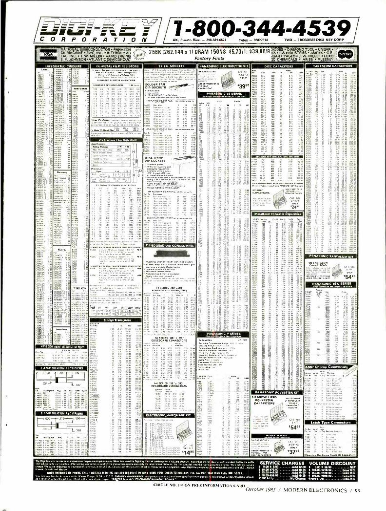
= I C O R P O R A T/ O N
1- 800 -344 -4539 AK, Puerto Rico - 218- 681 -b674 Telex - 62827914 TWX - 9103508982 DIGI KEY CORP
CIRCLE
OKMACHINE EEWC IINC.IINTE SNLAD 256K (262,144 x 1) DRAM 150NS $5.7011; $39.9519 ES DCWIND STTRESAMOEKGE. lEAC INC. J. W, MILLER AAVID ENGINE( GAR YAGEO J. W. MILLER LUXO E F' JOHNSON ATLANTICSEMICONDUC Factory Firsts 3C CHEMICALS ARIES PLESSEY
CD INTEGRATED
iá 60.56 1.1136
LWICN
0.61.LÚ
IAA IN 2.2
L
MVm
3.05C 12 3. 5134063 15 303
L30407 12 1 20
ur
CIRCUITS
r
4
In= .m.e,w po.rr.
v >aw set "` OMxe k 0.4. sp Va.. 500V
BTNORD BEBIROa YLUE TwsLL
iIII3:15MECI= mee Contee1 a m woven ena ngn 4.
°
DIP SOCKETS
9°7.7..
ITN TAIL ... No ......A
® ).m
evw
p m
t o
D '"?.:.?2""'L "7.. .rsm..r
WIRE WRAP { DIP SOCKETS _
N
.
maa
TEXAS INSTRUMENTS QUALITY
TIN PLATFO WIRE WRAP 61. 04. mu*. PA
m
WRAP
.t re 7 80 77 0
ww za zzam vnm
=I Is, , or ...RS CM. Nn.
P5200 -5b ONLY
P ts 96 d 439 CAPACITORS
MEDMIECIZEI1=111M1 Dm
0
Prom IS 0 500 75
Pme
7000 ICC 58
100 70
23 t
TANTALUM CAPACITORS
c° r. 3
71
10
22,
are u tm
815
18 10 Da 04
,: iá á7o a0á 4010 5 86 58130
R s, aaro CMO6
rw
00 rat 7e 7 970 at v o 7 or t.t . s ss 13 7
s 140 e7 N9 m) M2 590
t v9 973
PANASONIC LS SERIES
A. R.e«
°mp m
1 ®r M )
1 13 sea 13 20 a>'.
65.7 57 II.raj
2 2 25 18 54 12 83
B6 r " le ''
7
WOO
04 73 33 24 Al 3, 54 36
s
4 32 56 17 33
Now To Or., a. parr porme by ru
110 Wan PA MAN 81484 m[ m a 1aannn ,a. a9m M<w .n
5/ Carbon film Resstors
T
o 37 11 83 .7
3. 2
Sp opRh l S NM
r
,. ,°b..n,.
H
1
O
d
m
9 7 R2 7. 68K fal, _9,.,
7 42 390 3 63 33K 6706
,,n ....."
ASSORMAT 310 DISC u CAPACITORS
$ AT N
rM nun nn v e ñß8'
Metallized Polyester Capacitor
VW . ,
NC 29 0 7 64 2885
100 56 47 4 02 33.
-.
M 653
230 15
54824 .0 02
i
T I EDGEBOARD CONNECTORS
v
r .
Micro 174
.,
n
M.r sTn
.w sal ,w.r. ra ..r «mxo
RELIABLE coat ErrrcIENT C
mlwl. w..P . °mre0a.twrm In< E
k ¡ non, o
r.mrM .. d..Pr
,Rn ° ,..au y ra°d . .nr. :e a.n P
'PANASONIC TANTALUM KITTS
N TANTALUM CAPACITORS
§C5g3 CAT. NO. ¢IEf6Tÿ-1+. " E -KIT
nrs..s 6mSN
PANASONIC TSW SERIES
ra wi
13000 2 16 5. 167 CO
3000 1 51 II 61 105
15001 4 14 21 91 387 CC
m 1002 I 25 9M 87 ma 1 92 1437 /37
7m
B.
- - 2m
....mD ,wn a.n ., 0KO° c'
r'v IIE SERIES.l0g'R.200'
EDGEROARD CONNECTORS
26-17 4 70 05867 CS 17 3.
3623 630 61 40 3528 AA
0 A 26-49 10 CC 100 60 5 7a C5 50 7a
He SERIES .125. .80. 100ESOARD CONNECTORS
.° 9 9a so one 95 n
HE SERIES 160" 100 EDGESOARO CONNECTORS
. 1
-5 s. - a.i
A Un A
104 5064 10351 YOM 1
151 20 7tH Nv.
i-a z
n .013 m
CC
i ,rn.vaN w r5 475 .7n Mr LÿrN8
LM
Inteefece e.n
e...
ns
PANASONIC V- SERIES rr.yae M.r ak,e,r r.n c. ..dr.n
Es 4 066 TER
° Vsvrp
o
,ee.a °I.T Te4r.re -
.N°aN .
,
n . r
- P4612 0 2163
NAN 0 33 3. N 78 . 36 3 33 39 02 2011
. 5175
4116 200
52004 NO 15
ec 16.38431 D Rom
17 67 12 215. . r k S AMPSILICON
yyat b slate
rR t
,rery r m S.
m
MP Champ onnec nec OIR REC TIFIERS
r1.100 .205 -41.00 { I
N°° r
ss'..:84 r 74 15410140 lock
,
a .n Tw
en
eE°munL
PC ao.r,Nwn Ar
I ) .034 -4
.107
SIN^_ Y
moor sm.
.aS erwp
00 41 60 6m Iá Seta 111 m
170 METALLIZED POLYESTER
ASSOR 7 67. . 15 PoPutAll CAPACITORS RAMS
PANASONIC .. Lrry
6 yß P ;A'& CAT NG - 46'' E -KIT
S54"
40 CAPACITORS CAT. NO
dR0p6 3050P-Sit Il
0'" ONLY
:3786 eoa CPACUORe
3 AMP SILICON RECTIFIERS
1-1.000`4¡¡7-.375 1.000
ELECTRONIC HARDWARE KIT a
t.
1'b
CAT N0. 1E00.611
67486
e.... M Nee
^
Ea s Mounting Hardware Avelleble Sesnitly.
053 .210
P...
,Nmmt
T. Ch Key yowme discount and seryka charges are simple to apply. Most items sad by DigFKery may be COmbmed for a Volume discount Nems that are not discountable are identified by the suein SERVICE CHARGES -ND lollpwmg the pan number. After writing you, order, total an of the discountable Reins and apply the appropiale discount. To Ibis subtotal, add the non - t,aS,4 table items. then add the service clmrSe. We pet an 1.0w476 and insurance. eddrasses in the U.S.A., Canada and MalCO when check or money ord.. accompanies order. Dpi -Key only ships orderswrthin the continental U.S., Alaska. . 0.00-5 999 Add$0.75 Meese Canada and Mevrco. $ 10.00- $25.00 Add $0.75
WHEN ORDERING By PHONE, CALL 16003440536 105, Sall 216 -66166711. BY MAIL SEND YOUR ORDER T0: OIGFREV, P.O. Boa 677, Thiel River Falls, MN 56701. 8 25.00 -$49.99 Add 30.50 You may pay by chock. man order, Master Charge. VISA or C.0 D.OM. / -RFY GUARANTEE: Any ssd from Dyi Key r a vr,n 1., ru h r hvr n11 hr 1 rd or rrlrinrl $ 50.00- 399.99 Add $0.25 Na returned witmn90 days from teceiyt wnh a.5 3050lyour. avoice." PRIC ES SUBJECT TO CHANGE WIPNOUT NOTICE- $7000 &Up No Charge
VOLUME DISCOUNT 9 0.00 -$ 99.99 NET S 100.00- $249.99 Leis 10% $ 250.00- 3499.99 Lau 16 3 500.00- $999.99 Len 20% $10005 Up less 25%
NO. 1040N FREE INFORMATION CARD October 1985 / MODERN ELECTRONICS / 95
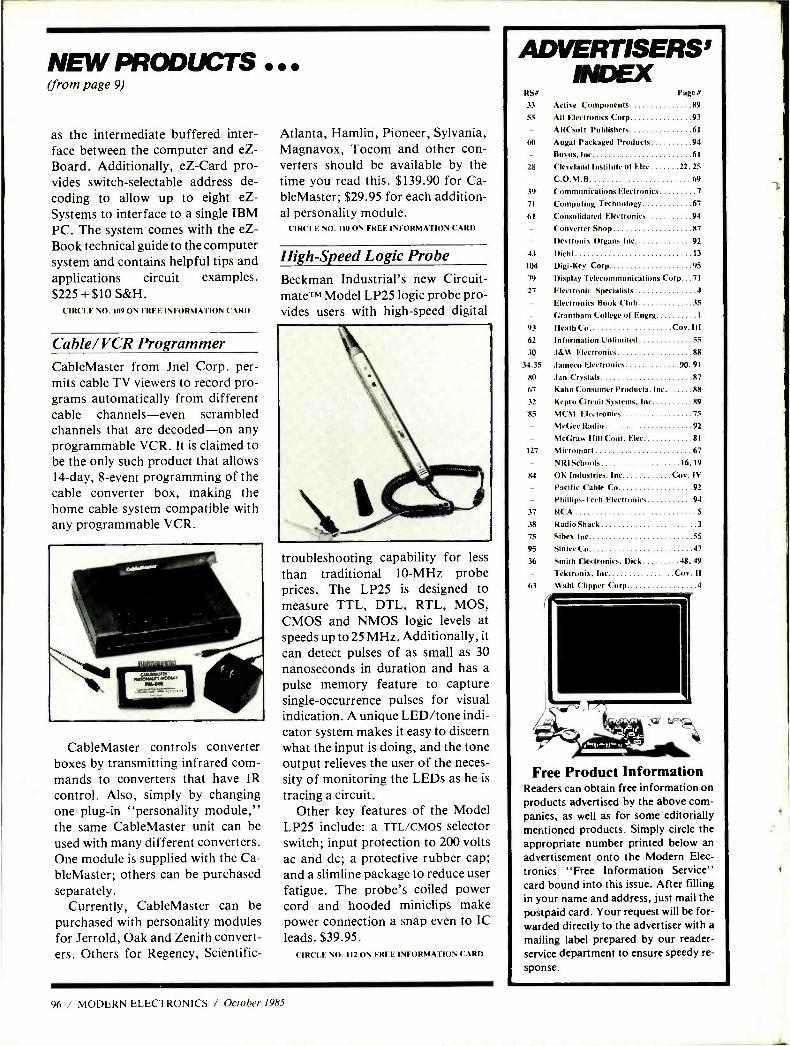
NEW PRODUCTS (from page 9)
as the intermediate buffered inter- face between the computer and eZ- Board. Additionally, eZ -Card pro- vides switch -selectable address de- coding to allow up to eight eZ- Systems to interface to a single IBM PC. The system comes with the eZ- Book technical guide to the computer system and contains helpful tips and applications circuit examples. $225 + $10 S &H.
CIR('I. F: O. 109 ON FRF.F: INFORMATION CARD
Cable /VCR Programmer CableMaster from Jnel Corp. per- mits cable TV viewers to record pro- grams automatically from different cable channels -even scrambled channels that are decoded -on any programmable VCR. It is claimed to be the only such product that allows 14 -day, 8 -event programming of the cable converter box, making the home cable system compatible with any programmable VCR.
CableMaster controls converter boxes by transmitting infrared com- mands to converters that have IR control. Also, simply by changing one plug -in "personality module," the same CableMaster unit can be used with many different converters. One module is supplied with the Ca- bleMaster; others can be purchased separately.
Currently, CableMaster can be purchased with personality modules for Jerrold, Oak and Zenith convert- ers. Others for Regency, Scientific-
Atlanta, Hamlin, Pioneer, Sylvania, Magnavox, Tocom and other con- verters should be available by the time you read this. $139.90 for Ca- bleMaster; $29.95 for each addition- al personality module.
CIRCLE NO. IIU ON FREE. INFORMATION CARD
High -Speed Logic Probe Beckman Industrial's new Circuit - mateTM Model LP25 logic probe pro- vides users with high -speed digital
troubleshooting capability for less
than traditional 10 -MHz probe prices. The LP25 is designed to measure TTL, DTL, RTL, MOS, CMOS and NMOS logic levels at speeds up to 25 MHz. Additionally, it
can detect pulses of as small as 30 nanoseconds in duration and has a
pulse memory feature to capture single- occurrence pulses for visual indication. A unique LED /tone indi- cator system makes it easy to discern what the input is doing, and the tone output relieves the user of the neces- sity of monitoring the LEDs as he is
tracing a circuit. Other key features of the Model
LP25 include: a TTL/CMOS selector switch; input protection to 200 volts ac and dc; a protective rubber cap; and a slimline package to reduce user fatigue. The probe's coiled power cord and hooded miniclips make power connection a snap even to IC leads. $39.95.
('IRCI.I: NO. 112 ON FREE INFORMATION CARD
96 / MODERN ELECTRONICS / October 1985
N
ADVERTISERS' INDEX
RSe l'age #
33 Active Components 89
55 All Electronics Corp 91
ARCsoft Publishers 61
60 Augat Packaged Products 94
- Buyus, Inc 61
28 Cleveland Institute of Flee 22, 25
- C.O.M.B. 69
39 Communications Electronics 7
71 Computing Technology 67
61 Consolidated Electronics 94
Converter Shop 87
Devironix Organs Inc 92
43 Diehl 13
104 Digi -Key Corp 95
79 Display Telecommunications Corp 71
27 Electronic Specialist 4
Electronics Book Club 35
Grantham College of Engrg 1
93 Heath('o (.ov'.III 62 Information Unlimited 55
30 J &w Electronics 88
34,35 Jameco Electronics 90, 91
80 Jan Crystals 87
67 Kahn Consumer Products, Inc 88
32 Kepro Circuit Systems, Inc 89
85 MCM Electronics 75
McGee Radio 92
- McGraw Hill Cont. Flee. 81
127 Micromarl 67
- NRI Schools 16, 19
84 OK Industries, Inc ('ov 1V
Pacific Cable Co 92
Phillips -Tech Electronics 94
37 RCA 5
38 Radio Shack 3
75 Sibex Inc. 55
95 Sinlec Co 47
36 Smith Electronics, Dick 48, 49
Tektronix, Inc ('ov. II 63 Wahl Clipper Corp 4
Free Product Information Readers can obtain free information on
products advertised by the above com- panies, as well as for some editorially mentioned products. Simply circle the
appropriate number printed below an
advertisement onto the Modern Elec-
tronics "Free Information Service" card bound into this issue. After filling in your name and address, just mail the
postpaid card. Your request will be for- warded directly to the advertiser with a
mailing label prepared by our reader -
service department to ensure speedy re-
sponse.
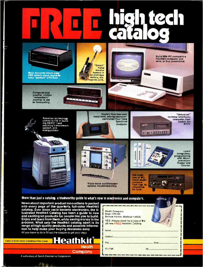
"Unit, ersal" terminal interfaces
computer, ham station for
RTT Y.
Most Accurate Clock uses SIBS atomic clock signal to keep "perfect" UTS time
Computerized weather station "remembers" weather to aid in forecasting.
Build IBN -PC compatib e Heathkit ;omputer and save, or buy assembled.
/ "Smart" metal
locator homes -in
on precious metals, dis-
regards junk.
Robotics t hnology comes to I f: it build- ing HERO I and teaching it rovemeit. speech. arc manipulation.
World's first low -cost hand -held, micreF rocessor-
controlled Real Time Spectrum Analyzer.
Learn computers,
programming wilt Micro- processor
Trainer and Course.
Triple -trace oscilloscJpe speeds troubleshooting.
Hw -54&). c ne of tri.a f nest mulü- purpose tam rigs in affordaile Ht fora.
I. saaigesaiikka
More than just a catalog a trustworthy guide to what's new in electronics and computes. News about important product innovations is packed into every page of the quarterly, full -color Heathkit catalog. Ever since racio became electronics, the il- lustrated Heathkit Catalog has been a guide to new and exciting kit products for people like you to build. Enjoy and learn from them, wile saving money in the process. What sets the Heathkit catalog apart is its range of high quality roducts and accurate informa- tion to help make your buyirg decisions easy. All you have to do is fill ou- He coupon to get yoLr copy
CIRCLE 93 ON FREE INFORMATION CARD Heathkit® Heath
Company A subsidiary of Zenith Electror cs Corporation
r Heath Company Dept. 079.344 Benton Harbor, Michigan 4902
YES Please send me a copy o rie all -new FREE Heathkit Zatalog.
Name
Addres,
City
CL -7EB
State
Zip
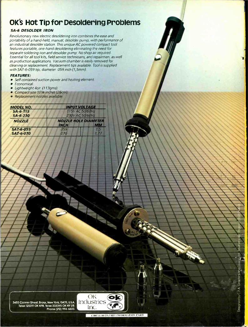
OK's Hot Tip for Desoldering Problems SA -6 DESOLDER IRON Revolutionary new electric desoldering iron combines the ease and portability of a hand -held, manual, desolder pump, with performance of an industrial desolder station. This unique AC powered compact tool features portable, one -hand desoldering eliminating the need for separate soldering iron and desolder pump. No shop air required. Essential for all tool kits, field service technicians, and repairmen, as well as production applications. Vacuum chamber is easily removed for cleaning or replacement. Replacement tips available. Tool is supplied with SAT -6 -059 tip; diameter .059 inch (1,5mm).
FEATURES: Self contained suction power and heating element. Economical. Lightweight 4oz. (113gms). Compact size 101/4 inches (26cm). Replacement nozzles available.
MODEL NO. INPUT VOLTAGE SA -6 -115 115V AC 50 /60Hz SA -6 -230 230V AC 50 /60Hz
NOZZLE NOZZLE HOLE DIAMETER INCH MM
SAT -6 -059 059 1, 5 SAT -6 -070 .070 1, 77
OK Industries
Inc.
_ a 111111111111111110111MMIL 111111111110111111
11111111 r111111111111111MIL t t1111111111111111111111111V
ar1111111111111111111111M won IMIL ''' __ __ ,.. . ___ 111-- m Ayr
4 !F 0 ' U
3455 Conner Street, Bronx, New York.10475, U.SA Telex 1250910K NYK. Telex 232395 OK NY UR.
Phone (212) 994 -6500.
CIRCLE 84ON F RI I INFORMATION CARD


![Design of On-Chip Crossbar Network Topology Using Chained Edge Partitioningdtl.yonsei.ac.kr/docs/International_Journal/[2010][COMPJ... · · 2014-03-10Design of On-Chip Crossbar](https://img.dokumen.tips/doc/110x75/5adb35597f8b9add658da793/design-of-on-chip-crossbar-network-topology-using-chained-edge-2010compj2014-03-10design.jpg)