Embed Size (px)
Citation preview

© Copyright 2010 Xilinx, Inc. All Rights Reserved.XILINX, the Xilinx logo, the Brand Window and other designated brands included herein are trademarks of Xilinx, Inc. All other trademarks are the property of their respective owners.
NOTICE OF DISCLAIMER: The information disclosed to you hereunder (the “Information”) is provided “AS-IS” with no warranty of any kind, express or implied. Xilinx does not assume any liability arising from your use of the Information. You are responsible for obtaining any rights you may require for your use of this Information. Xilinx reserves the right to make changes, at any time, to the Information without notice and at its sole discretion. Xilinx assumes no obligation to correct any errors contained in the Information or to advise you of any corrections or updates. Xilinx expressly disclaims any liability in connection with technical support or assistance that may be provided to you in connection with the Information. XILINX MAKES NO OTHER WARRANTIES, WHETHER EXPRESS, IMPLIED, OR STATUTORY, REGARDING THE INFORMATION, INCLUDING ANY WARRANTIES OF MERCHANTABILITY, FITNESS FOR A PARTICULAR PURPOSE, OR NONINFRINGEMENT OF THIRD-PARTY RIGHTS.
Revision History
Date Version Description10/05/10 12.3 Recompiled under 12.3.
07/23/10 12.2 Recompiled under 12.2.

Overview
Spartan-6 MultiBoot Capability Xilinx SP605 Board Software Requirements SP605 Setup Compiling the MultiBoot Design Run MultiBoot Design Spartan-6 MultiBoot Details References
Note: This presentation applies to the SP605

Spartan-6 MultiBoot Capability
What is MultiBoot?– The MultiBoot feature allows the FPGA application to load two or more FPGA
bitstreams under the control of the FPGA application. The FPGA application triggers a MultiBoot operation, causing the FPGA to reconfigure from a different configuration bitstream. After a MultiBoot operation is triggered, the FPGA restarts its configuration process as usual.
– More details can be found in UG380
MultiBoot Capability– FPGA application controlled configuration – Bitstream selection of multiple applications
Safe Update – Golden bitstream– Upgradeable bitstream– Failure recovery
• Possible Triggers (CRC error, IDCODE error, WDT timeout)
Note: Presentation applies to the SP605

SP605 MultiBoot Design Description
Description– Reconfiguration of FPGA based on error condition or command from user
logic. Spartan-6 MultiBoot logic used to clear configuration memory and restart the configuration process (REBOOT) from an external non-volatile memory (e.g. SPI Flash). Location of new bitstream is determined by dedicated Spartan-6 address registers (General_1 to General_4)
Reference Design IP– RTL state machine utilizing ICAP primitive and
IPROG command to initiate REBOOT– RTL counter– RTL logic for Pushbutton inputs and LED outputs
Reference Design Source and Application– rdf0028.zip– Available through http://www.xilinx.com/sp605
Note: Presentation applies to the SP605

Upgrade Example
MultiBoot: Process by which the FPGA selectively reprograms and reloads its bitstream from an attached external memory.
Safe update: Field updating bitstream storage with a new bitstream in such a manner to prevent any failure due to a failure in the update process. This is accomplished with the enhanced MultiBoot available in Spartan-6.
((( )))
Base Station
Remote Towers
Upgrading all systems to v1.3
S-6Design
Revisions
Can a multi-boot system be implemented without safe update design considerations?
Yes – If there are no potential for disruptions during flash loading
How is a system upgraded?1. New multi-boot image is created2. System setup to receive the new image3. User application erases section of Flash4. The new image is delivered into the system’s Flash5. User application resets system
1.2
1.0
1.3
Note: Presentation applies to the SP605

Xilinx SP605 Board
Note: Presentation applies to the SP605

ISE Software Requirement
Xilinx ISE 12.3 software
Note: Presentation applies to the SP605

Setup for the SP605 IBERT Designs
Connect a USB Type-A to Mini-B cable to the USB JTAG connector on the SP605 board– Connect this cable
to your PC

SP605 Setup
Set the mode pins for SPI Flash
– M0 = 1– M1 = 0

SP605 Setup
Disable System ACE– Turn S1 #4 off– Or remove CF
Card

SP605 Setup
Turn SP605 Board power on

Compile MultiBoot Design
Unzip the rdf0028.zip file– Available through http://www.xilinx.com/sp605
Note: Presentation applies to the SP605

Compile MultiBoot Design
At a command prompt, type:cd sp605_multibootrun_all_build_script.bat
Note: Takes about five minutes

Program SPI MultiBoot Design
Open iMPACTimpact
Note: Presentation applies to the SP605

Program SPI MultiBoot Design
Select– Create a new project– Configure devices using
Boundary Scan (JTAG)
Note: Presentation applies to the SP605

Program SPI MultiBoot Design
Right click on the “SPI/BPI ?” box and select Add SPI/BPI Flash…– Select the <Design path>\PROM_files\header_golden_multiboot.mcs
Note: Presentation applies to the SP605

Program SPI MultiBoot Design
In the Select Attached SPI/BPI GUI, select– SPI PROM– W25Q64BV– Data Width: 1
Note: Presentation applies to the SP605

Program SPI MultiBoot Design
Program the SPI Flash:– Right-click on the Flash and select Program
Note: Programming takes about fifteen minutes

Program SPI MultiBoot Design
Erase Before Programming must be selected
Note: Presentation applies to the SP605

Run MultiBoot Design
Cycle board power– The multiboot_image design boots
The LED pattern will show a double flash of the four LEDs Press SW7 (1)
– This issues a REBOOT command to Spartan-6 configuration logic
– The DONE led (DS17) (2) will go out momentarily
– The SP605 will reboot into the double flash design (3)
Note: Presentation applies to the SP605
2
1
3

Run MultiBoot Design
Press SW5 (1)– This will simulate a failed programming of the multiboot_image design– SW5 performs a sector erase at the start of the multiboot_image in Flash
Note: Presentation applies to the SP605
1

Run MultiBoot Design
Press SW7 (1)– This issues a REBOOT command to Spartan-6 configuration logic – The DONE led (DS17) (2) will go out momentarily– The SP605 will reboot into the golden_image, a single flash design (3)
This shows the loading of the golden original file in case of a programming failure
Note: Presentation applies to the SP605
2
1
3

Spartan-6 MultiBoot Details

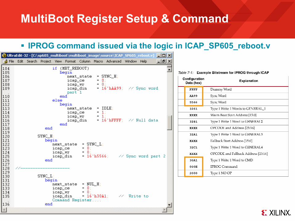
MultiBoot Register Setup & Command
General Configuration Registers– Sticky 16-bit registers that are maintained after reboot
• General 1, 2 - Set to hold address of Multi-boot bitstream • General 3, 4 - Set to hold address of Golden bitstream• General 5 - User Data
– All registers loaded at base address of Flash (SPI or BPI) and constant– Bitfiles and designs (ICAP commands) are independent of addressing
REBOOT command – Loads multi-boot image directly– Issued via ICAP to reload multi-boot address space– Jumps to address based on Strike Count, which increments on a failure
• Load Multi-boot (Gen 1,2) when Strike Count < 3• Load Golden (Gen 3,4) when Strike Count < 6
See UG380 for MultiBoot details
Note: Presentation applies to the SP605

MultiBoot Register Setup & Command
Below is a sample of the boot header HEX file, boot_header_only_SPI_x1.hex To change the Golden image and MultiBoot image address locations to a
different location in the SPI Flash– Edit the boot_header_only_SPI_x1.hex. See the highlighted numbers below.– Edit the promgen command in the run_all_build_script.bat. Specifically the promgen "-u
<address>" values need to match the boot header HEX value locations.
FFFFFFFF // DUMMYWORD, DUMMYWORD
AA995566 // SYNCWORD
31E1FFFF
32610000 // 32A1=GENERAL1 0x0000=address[15:0] MultiBoot image location
32810340 // 3281=GENERAL2 0x03=SPIx1 read command, 0x40=address[23:16] MultiBoot image address
32A10000 // 32A1=GENERAL3 0x0000=address[15:0] Golden image address location
32C10301 // 32C1=GENERAL4 0x03=SPIx1 read command, 0x01=address[23:16] of Golden image address
32E10000
30A10000
33012100
3201001F
30A1000E
20002000 // NOOP, NOOP
20002000 // NOOP, NOOP
Note: Presentation applies to the SP605
MultiBoot Register Setup & Command
IPROG command issued via the logic in ICAP_SP605_reboot.v

Baseline
Golden
User Data
Multi-boot
Baseline1 – Set General 1,2,3,4,5
and other registers2 – Issue Reboot
Configuration FailsAttempt up to 3 times
and increment Strike Count
Memory Map
Spartan-6 Memory Map & Flow Diagram
General 3,4
General 1,2
General 5
Start
Flow Diagram
Multi-boot3 – Configure4 – Run design 5 – Re-image flash6 – Issue Reboot
Golden 7 – Configure8 – Run design9 – Re-image Flash10 – Pulse PROG or
Power Cycle
Prot
ecte
d Se
ctor
s
Sector 16
Sector 14
Sector 1
Sector 0

Design Requirements
Spartan-6 Multi-boot and Golden Designs
Data Link
Send and receiveapplication data and new images
Flash access
Read and writeapplication data and new images
SPIOR
BPI
BitGen Options-g next_config_register_write:Enable
-g reset_on_error:yes
Ethernet,or other link
BaselineManually created with SYNC, General Registers, and REBOOT command
BitGen will auto create in tools as part of Golden image
Note: Presentation applies to the SP605
Multi-boot controllerw/ ICAP
- Track multi-boot attempts via General 5 and BOOT_STS for Strike Count- Issue REBOOT(Multi-boot Only)- Power cycle or Pulse Prog(Golden Only)

Upgrading Flash
Steps in the multi-boot and safe update process: Erase: What if the power goes down?
– Erased flash will contain all F’s in erased locations starting from bottom up
– Partial erasing will erase SYNC word and config attempts will time out
– CFG_TIMER will trigger reboot of “Golden Image”– CFG_TIMER value can be adjusted
Program: What if the power or data link goes down?– Loading bitfile in top down method will write the SYNC word last– The flash will be in the same condition as a partially erased
flash– Error management is now the same as Erased condition
Verify: Problems during this phase?– Any CRC error will trigger a reload of the Golden image
Re-start system – Issue REBOOT via ICAP from multi-boot application– Pulse PROG or cycle power to reset system after Golden load
Erased
Programmed
All F’s
.bit
SYNC word
Half ErasedEnd of .bit
All F’s
Half ProgrammedEnd of .bit
All F’s
Flash Memory States
00
FF
00
FF
00
FF
00
FF
Note: Presentation applies to the SP605

References

References
Spartan-6 Configuration– Spartan-6 FPGA Configuration User Guide – UG380
http://www.xilinx.com/support/documentation/user_guides/ug380.pdf

Documentation

Documentation
Spartan-6– Spartan-6 FPGA Family
http://www.xilinx.com/products/spartan6/index.htm
SP605 Documentation– Spartan-6 FPGA SP605 Evaluation Kit
http://www.xilinx.com/products/devkits/EK-S6-SP605-G.htm– SP605 Getting Started Guide
http://www.xilinx.com/support/documentation/boards_and_kits/ug525.pdf– SP605 Hardware User Guide
http://www.xilinx.com/support/documentation/boards_and_kits/ug526.pdf– SP605 Reference Design User Guide
http://www.xilinx.com/support/documentation/boards_and_kits/ug527.pdf