Embed Size (px)
Citation preview
- 1 -
XRT Smart Power® Hydraulic Generator System
Installation and Operators Manual
THE LIBERATOR

2
Smart Power® Liberator Installation & Operations Manual
Table of Contents Introduction
3
Pump I.D. & Hose Runs to Open Center Valve Valve location Component Installation Oil Reservoir Tank
4
Hose Schematic 12
Connecting Open Center Valve/Control Blocks & Pressure Adjustments
14
Hose Specifications
16
Fluid Specifications
17
Open Center Valves
21
4th Reel & Diverter Valve Schematic
28
Installation Check List
29
System Test
30
Troubleshooting Guide
31
Certificate of Warranty
32
Contact Information
33
MANUFACTURED BY: XRT Power Systems
A division of Hansen Marine Engineering, Inc. 32 Tioga Way
Marblehead, MA 01945

3
Introduction: Please read complete installation manual before attempting installation. The XRT Hydraulic Pump System is a dual level hydraulic pump designed to operate one, two or three hydraulic extrication tools at the same time. Each pump circuit has two pumps assigned providing a total of 6 possible pumps for three circuits. Each individual circuit is completed with a control block assembly and an open center valve. The XRT system provides rescue personnel the ability to operate 3 extrication tools simultaneously, independent of each other, in order to implement a rapid rescue attempt. XRT Power Systems manufactures models for both low-pressure systems (5,000 PSI) and high-pressure systems (10,000 PSI). NOTE: Each system has specific hose, and fluid requirements. The XRT Smart Power® Liberator System is a two-stage multiple tool port hydraulic and AC power truck mounted system. The XRT Pump is attached to the generator portion of the Smart Power® hydraulic generator system. This allows the XRT Tool Systems to be used regardless of input engine speed. Engine speed and electrical AC output can vary without interruption of use of the XRT Tool System. It utilizes open center valves and is mounted to the truck. When the selected tool or tools are engaged, the flow is diverted to the tool. At that point the tool will close steadily until it meets resistance. This causes the XRT low-pressure hydraulic pump to disengage, bypassing 75% of the total fluid and leaving 25% of the fluid to finish the work. When the tool is reversed, the flow resumes to the full flow to open the tool. Full flow and full pressure is provided at each power port via an engineered, dual level, pump system. The dual level system utilizes an individual pump for each level and an individual system for each power port. XRT Smart Power® Liberator System includes:
• Smart Power® Generator (10, 15 or 20 KW, 60 Hz) • 3.5 Gallon Stainless Steel Reservoir tank with sight gauge, temperature
gauge and filter assembly. • XRT Pump with fittings (mounted on the backend of the generator) • One Open Center Valve/Control Block assemblies per tool port ordered. • Owners & Installation manuals. • Oil Cooler • Suction Hose from reservoir to pump.
Note: Pressure and return hose for installation are not included. These lengths are dictated by the distance of the control valve from the pump, and must be ordered separately.
4
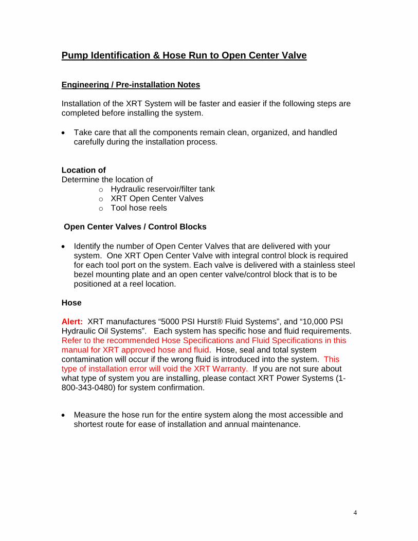
Pump Identification & Hose Run to Open Center Valve Engineering / Pre-installation Notes Installation of the XRT System will be faster and easier if the following steps are completed before installing the system.
• Take care that all the components remain clean, organized, and handled
carefully during the installation process. Location of Determine the location of
o Hydraulic reservoir/filter tank o XRT Open Center Valves o Tool hose reels
Open Center Valves / Control Blocks
• Identify the number of Open Center Valves that are delivered with your
system. One XRT Open Center Valve with integral control block is required for each tool port on the system. Each valve is delivered with a stainless steel bezel mounting plate and an open center valve/control block that is to be positioned at a reel location.
Hose Alert: XRT manufactures “5000 PSI Hurst® Fluid Systems”, and “10,000 PSI Hydraulic Oil Systems”. Each system has specific hose and fluid requirements. Refer to the recommended Hose Specifications and Fluid Specifications in this manual for XRT approved hose and fluid. Hose, seal and total system contamination will occur if the wrong fluid is introduced into the system. This type of installation error will void the XRT Warranty. If you are not sure about what type of system you are installing, please contact XRT Power Systems (1-800-343-0480) for system confirmation.
• Measure the hose run for the entire system along the most accessible and
shortest route for ease of installation and annual maintenance.

5
• Each power port for the system requires the following: o (2) Hoses in a run from the pump to the Control Blocks. These are
the pressure hoses. o (1) Hose in a run from the Control Block to the return manifold at
the filter on the reservoir tank. This is the return line. o One set of “Lead-In Lines” from each XRT Open Center Valve to
each hose reel. Often these lines are included with the Hose Reels.
• Note: Hoses are cut and fitted specifically for your vehicle. Be careful to
allow for proper hose length for your installation. Should you decide to order the hose from a local supplier, please refer to the Spec. Sheet (Page 13) for proper hose specifications.
Please contact XRT Power Systems at (781)-631-3282 to order the measured hose lengths, and for all engineering and installation questions.
Component Installation The following location guidelines should be observed during installation. Note: The XRT Pump System is delivered pre-mounted on the Smart Power® Generator. Disassembly of the pump is not necessary for the installation. The XRT pump will extend out approximately an additional 3.75” from the back end of the Smart Power® specification. Plan for that additional length when installing the generator. Follow normal Onan Protec® installation procedure for proper generator installation. If you have any technical questions before, during or after installation, please call the XRT Power Systems technical assistance line at 1-800-343-0480 ext. 125 (International Direct line 781-639-7125). Once the Generator is properly installed, you can begin installation of the XRT portion of the system, starting with System Layout. Caution: Do not engage the PTO/Generator until the XRT Powerhouse is properly installed, and filled with fluid.
6
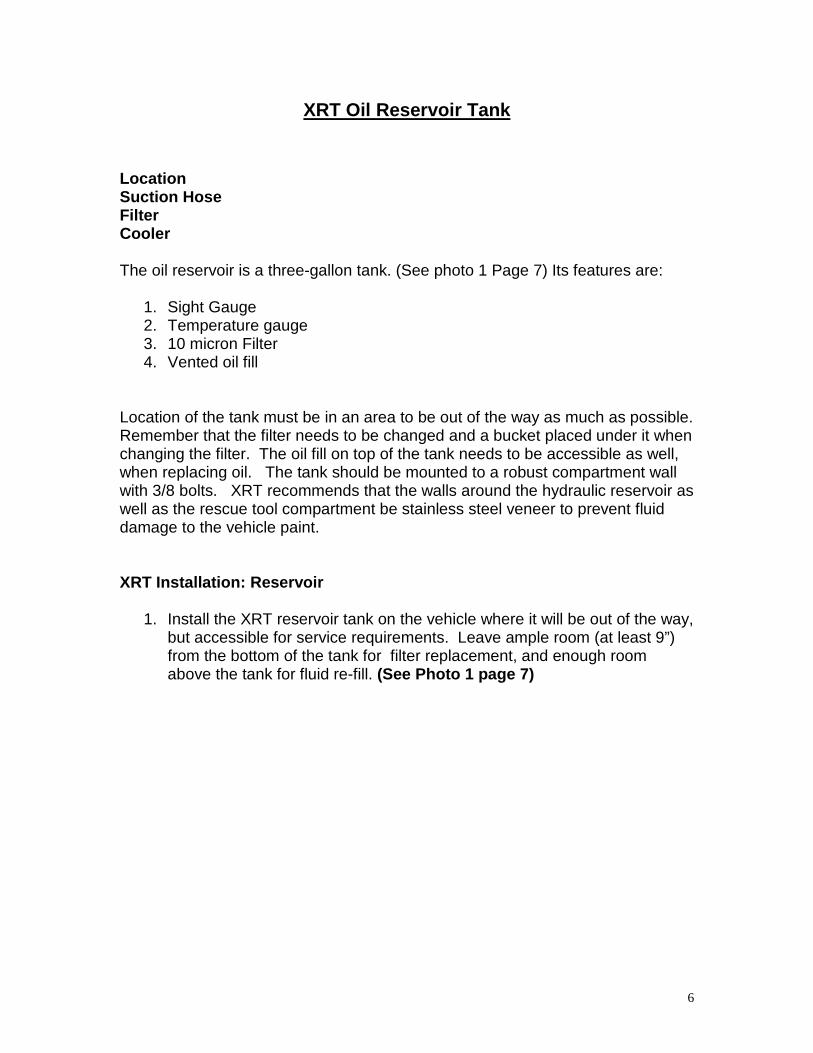
XRT Oil Reservoir Tank
Location Suction Hose Filter Cooler The oil reservoir is a three-gallon tank. (See photo 1 Page 7) Its features are:
1. Sight Gauge 2. Temperature gauge 3. 10 micron Filter 4. Vented oil fill
Location of the tank must be in an area to be out of the way as much as possible. Remember that the filter needs to be changed and a bucket placed under it when changing the filter. The oil fill on top of the tank needs to be accessible as well, when replacing oil. The tank should be mounted to a robust compartment wall with 3/8 bolts. XRT recommends that the walls around the hydraulic reservoir as well as the rescue tool compartment be stainless steel veneer to prevent fluid damage to the vehicle paint.
XRT Installation: Reservoir
1. Install the XRT reservoir tank on the vehicle where it will be out of the way, but accessible for service requirements. Leave ample room (at least 9”) from the bottom of the tank for filter replacement, and enough room above the tank for fluid re-fill. (See Photo 1 page 7)
7
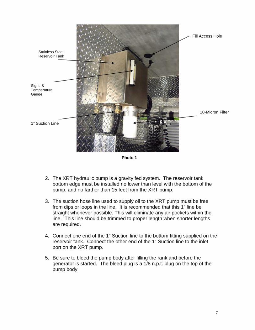
2. The XRT hydraulic pump is a gravity fed system. The reservoir tank bottom edge must be installed no lower than level with the bottom of the pump, and no farther than 15 feet from the XRT pump.
3. The suction hose line used to supply oil to the XRT pump must be free
from dips or loops in the line. It is recommended that this 1” line be straight whenever possible. This will eliminate any air pockets within the line. This line should be trimmed to proper length when shorter lengths are required.
4. Connect one end of the 1” Suction line to the bottom fitting supplied on the
reservoir tank. Connect the other end of the 1” Suction line to the inlet port on the XRT pump.
5. Be sure to bleed the pump body after filling the rank and before the generator is started. The bleed plug is a 1/8 n.p.t. plug on the top of the pump body
Stainless Steel Reservoir Tank
Sight & Temperature Gauge
1” Suction Line
10-Micron Filter
Photo 1
Fill Access Hole

8
Connecting Hose Lines
• Hose Lengths: Smart Power® system requires 3 hose connections; two
¼” pressure lines, and one 3/8” return line) per tool circuit. It is important to order the correct lengths of each pressure and return line, as these are custom to each vehicle. Each tool port requires one low pressure high flow ¼” orange hose line (Pump Group A), one high pressure low flow ¼” black or blue hose line (Pump Group B), and one 3/8” black return line.
Refer to the picture on the following page of the Smart Power® Liberator system, with each Pump Group identified.
Pump Group “A”, (See Photo 2) is the high volume, low-pressure pump group. Pictured here along with the assembly, it houses up to a total of three independent pumps. The orange hoses are attached to this pump. The maximum pressure on this pump is 2,000 PSI. See hose specifications
Pump Group A
Photo 2 Group A Low Pressure
High Volume

9
Pump Group “B” (See Photos Below) is the high pressure, low volume-cutting pump. Each radial tower is a pumping element. The blue/black hoses are attached here. The hydraulic fluid used dictates the type and pressure rating of this hose. The maximum operating pressure of this pump is 5000PSI if you have a Hurst System that uses Hurst Oil (Phosphate Esther) and 10,000PSI if you have a Hydraulic Oil System. See hose specifications.
Photo 3 Pump Group B
High Pressure – Low Volume
Pump Group B High Pressure ¼” Hose
1” Suction Hose Inlet from reservoir tank.
10
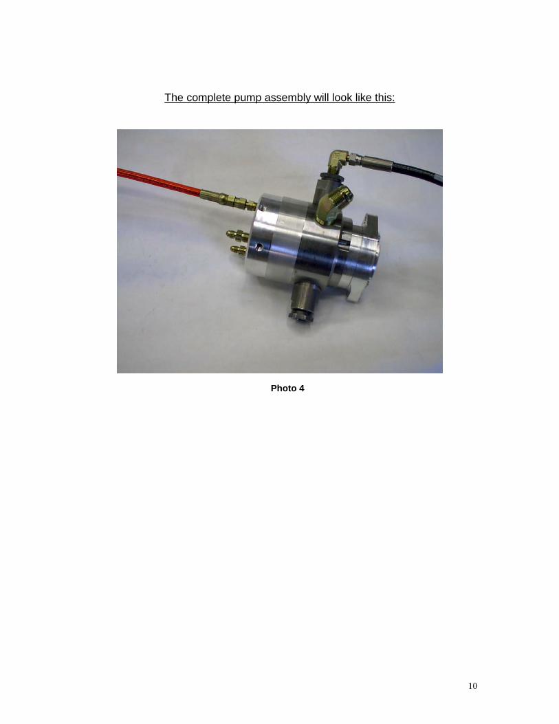
The complete pump assembly will look like this:
Photo 4

11
Photo 1 - Oil Reservoir Tank
Return Flow: Return lines are 3/8” in size. All Return lines go back to the reservoir. The line is specified in the hose specifications. The return pressure is approximately 35 PSI and the hose specification is more for stability than pressure.

12

13
• Installation Hint: • When two Open Center Valves are located in the same compartment, one
return line may be used. A maximum of two Open Center Valves/Control blocks may share a mutual return line back to the Return Block on the Stainless Steel shroud. The Return Block is designed to accommodate three returns.
• We recommend Red Lok-Tite 545 for all fittings. Do not use Teflon tape or other plumbing sealer.
• Hoses are cut and fitted specifically for your vehicle. Be careful to allow for proper hose length for your installation. Should you decide to order the hose from a local supplier, please refer to the Hose Specification Sheet for proper hose selection.
Please contact XRT Power Systems at (781)-639-7125 to order the measured hose lengths, and for all engineering and installation questions.

14
Connecting the Open Center Valves / Control Blocks: Each Open Center Valve / Control Block, (See Photo 5) has three hose connections. A metallic identification label has been placed on the back of each block to help identify the connections. NOTE: If the Valves that you are installing do not have the above-mentioned labels, please contact XRT Power Systems at 781-639-7125 for assistance. Otherwise refer to the picture below. Connect the orange line to the Group “A” fittings. Connect the black line to the Group “B” fittings. Since all line hoses (black or orange) originate from independent pumps, each Control Block requires (1) Black and (1) Orange hose to complete the circuit. The third line connected to each control block is the 3/8 Return line mentioned above. This line then goes to the return manifold on the reservoir. Pressure Adjustment: All XRT systems are tested as a complete system before they are shipped. Pressures are pre-set, but adjustments are sometimes necessary. Setting Pressure:
1. Connect a liquid filled pressure gauge that can handle up to 10,000 PSI on the pressure line at the end of the hose reel. This should be the male fitting.
2. Open the valve and let the pressure rise to maximum pressure. 3. Loosen Jamb nut on the High Pressure Adjuster (see picture #5) 4. With a flat screwdriver, adjust slowly the pressure. Turn the screw until
the desired pressure is set. 5. Re-lock the jamb nut. Close the valve, releasing the pressure.

15
Photo 5 – Open Center Valve/Control Block connection, Backside

16
Hose Specifications
Suction Line Hydraulic Oil - SAE 100R4-16 – Black Rubber hose (supplied) Hurst Oil Phosphate Ester - 12 PTFE with stainless steel over-braid (supplied) Both ends on either hose style have Female JIC Ends Return Line Return Line from control blocks to oil reservoir tank - Always use 3/8” for the return line. Parker Parflex 518-C SAE-100R7 3/8” diameter Both ends have 3/8” Female JIC fittings Note: This hose can be used with both Hydraulic Oil and Phosphate Ester fluid. The pressure on the return line is approximately 30 PSI. XRT recommends 518C Hose to allow for sharper bends in the hose routing. This hose is rated at 4000 PSI. This was selected for hose stability going around corners. Pump Group A – ¼” Low Pressure Line Low pressure line from group “A” pumps to control blocks. Parker Parflex 520N-4-100R8 x ¼” diameter (Working pressure of 5,000 PSI.) The hose can be used for any fluid. The pressure on this circuit is approximately 2000 PSI. We suggest using orange color hose. Both ends to have ¼” Female JIC fittings. Pump Group B – ¼” High Pressure Line – 5000 PSI For All Hurst® Fluid (Phosphate Esther Systems) High Pressure lines from group “B” pumps to control blocks. Parker Parflex 520N-4-100R8 x ¼” diameter with Female JIC fittings on both ends. The pressure on this circuit is 5000-5200 PSI, for phosphate ester systems. For Phosphate Ester Systems use the same spec as group “A” but use a different color, we suggest black hose Pump Group B – ¼” High Pressure Line – 10,500 PSI For all 10,500 PSI Hydraulic Oil Systems: Parker Polyflex 2245N-04V00 ¼” diameter with Female JIC fitting on both ends. The pressure on this circuit is approximately 10,000 PSI. We suggest black hose

17
Fluid Specifications CAPACITY
3.5 Gallons Systems I/II/III
Not including vehicle hoses
FLOWS
0-2000 PSI 240 cu in., 4 liters
2000-10000 PSI 60 cu in., 1 liter
2000-5000 PSI 120 cu in., 2 liter for Phosphate Ester Systems
FILTRATION
10 micron absolute
Filter No. XRT 412 or XRT 412 PE for Phosphate Ester Systems
OIL REQUIREMENTS
5000 PSI Hurst® Systems – Hurst® Oil
Alert: Phoenix Rescue System “Phosphate Ester” is not authorized for the XRT System
10,000 PSI Systems – ISO 22 W Hydraulic Oil
SEALANT REQUIREMENTS Loctite® 545 No liquid Teflon based sealants

18
Oil Cooler
Hydraulic Oil Cooler
Each XRT Smart Power® Liberator System includes an auxiliary oil cooler/fan that needs to be inserted into the oil flow circuit, and connected to 12 Volts. See pictures on next page. There are two 3/8” JIC male fittings at the bottom of the cooler. Connect one of the return lines from the Open Center Valve/Control Block to the right/left inlet port in the cooler, and connect another 3/8” line from the right/left connection back to the oil reservoir tank manifold to complete the cooling circuit. This needs to be inserted into only 1 circuit of the return lines
Oil Cooler
Connect the Red line to Positive (+). Connect the Black line to Negative (-).

19
Oil Cooler – Back Side
Connect one of the 3/8” return lines coming from an Open Center Valve/Control Block, into one of the 3/8” JIC fitting on the bottom of the cooler.
Complete the circuit by connecting another 3/8” line to the second fitting shown to one of the return fittings on the manifold assembly at the bottom of the reservoir tank. See picture on page (18).
20
21
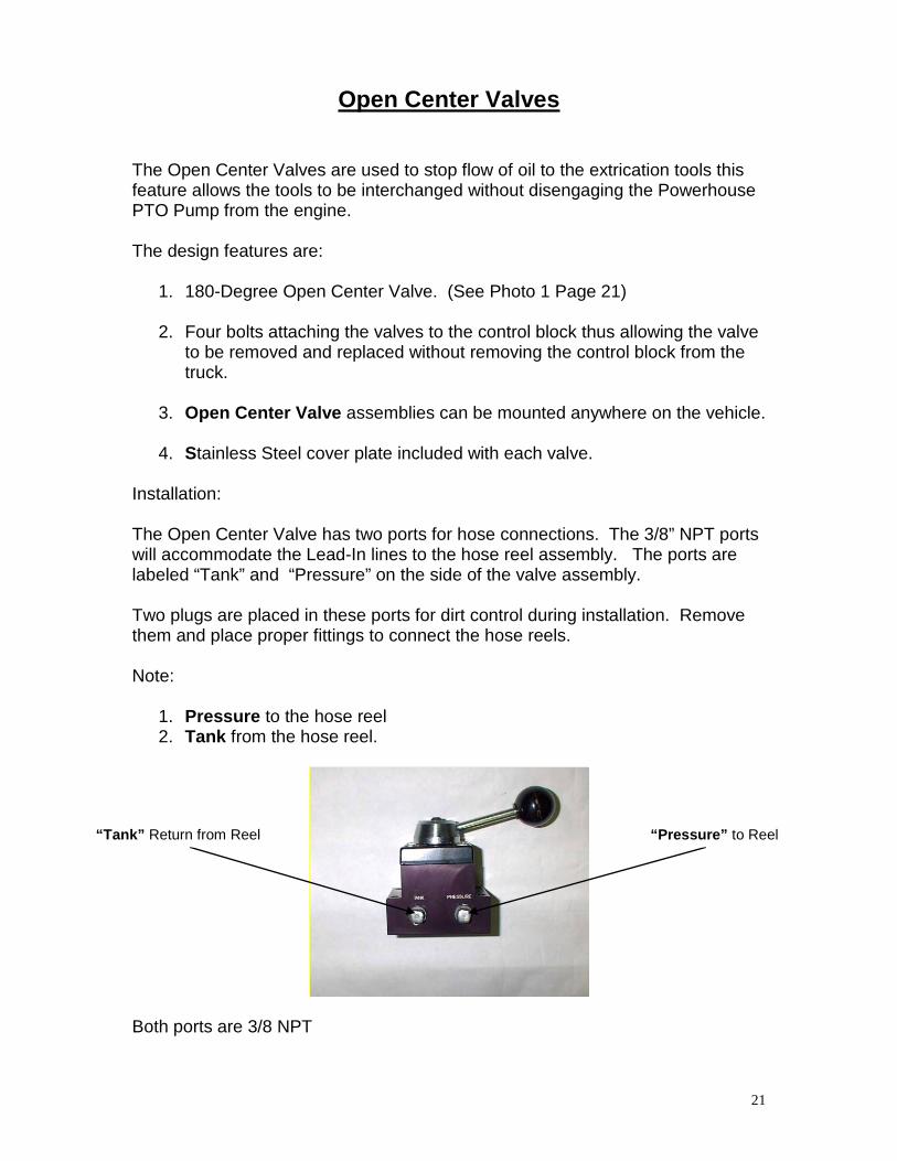
Open Center Valves
The Open Center Valves are used to stop flow of oil to the extrication tools this feature allows the tools to be interchanged without disengaging the Powerhouse PTO Pump from the engine. The design features are:
1. 180-Degree Open Center Valve. (See Photo 1 Page 21) 2. Four bolts attaching the valves to the control block thus allowing the valve
to be removed and replaced without removing the control block from the truck.
3. Open Center Valve assemblies can be mounted anywhere on the vehicle.
4. Stainless Steel cover plate included with each valve.
Installation: The Open Center Valve has two ports for hose connections. The 3/8” NPT ports will accommodate the Lead-In lines to the hose reel assembly. The ports are labeled “Tank” and “Pressure” on the side of the valve assembly. Two plugs are placed in these ports for dirt control during installation. Remove them and place proper fittings to connect the hose reels. Note:
1. Pressure to the hose reel 2. Tank from the hose reel.
Both ports are 3/8 NPT
“Tank” Return from Reel “Pressure” to Reel

22
Photo 1 – Open Center Valve w/Mounting Plate
Front Bumper Two tool Installation
23
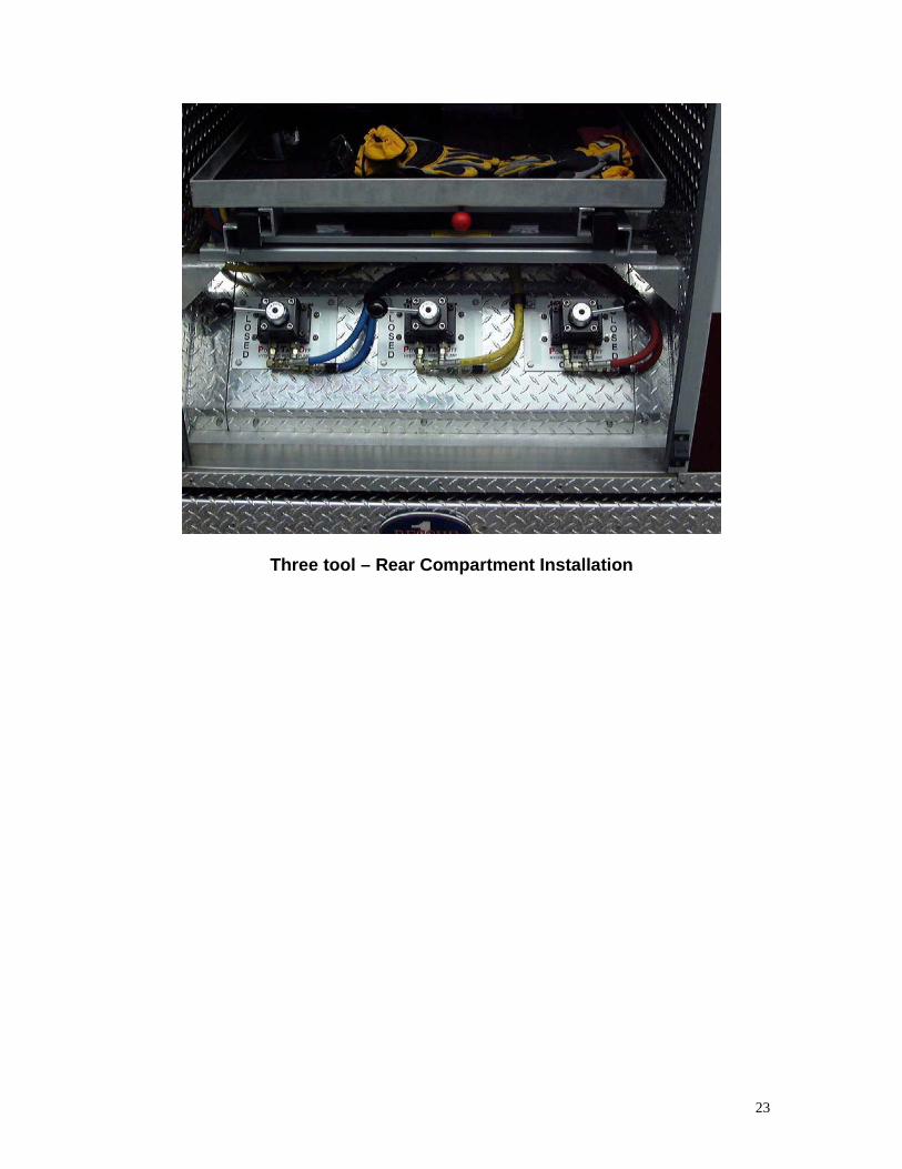
Three tool – Rear Compartment Installation

24
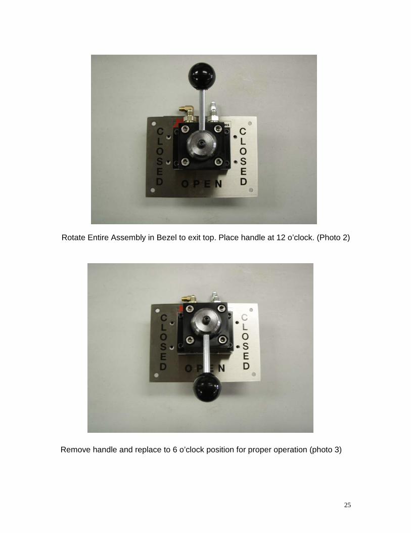
OPEN CENTER VALVE – TOP EXIT TO REELS When locating the open center valve hose routing should be considered during layout, particularly the connection to the reels. In layout if the hose exit to the reels is better leaving the top of the open center valve DO NOT REMOVE the plugs marked “A” and “B” for entry into the valve. Entry into the valve through “A” and “B” will render the open center valve inoperative. If exiting the open center valve toward the top is necessary then simply turn the entire open center valve assembly over there by having the “pressure” and “tank” ports facing upwards. Once this is done, the open center calve handle must be re-indexed to operate correctly. To re-index the valve simply place the valve handle in the 12 o’clock position, then remove the center retaining screw, remove the handle and replace on the splined shaft at the 6 o’clock position, replace the set screw. Turn the handle in both directions to ensure the valve swing is even, closed at 3 o’clock and 9 o’clock. The valve is now functional
Standard Bottom Exit (photo 1)
25
Rotate Entire Assembly in Bezel to exit top. Place handle at 12 o’clock. (Photo 2)
Remove handle and replace to 6 o’clock position for proper operation (photo 3)

26
The Diverter Valve The purpose of the diverter valve is to be able to add an additional reel to the vehicle. In doing so, you will be able to change the location of the active reel utilizing one of the pump circuits. Since the XRT has a maximum of three pump circuits a diverter valve can be added to any circuit to include a second reel to that circuit. A typical installation scenario would be two reels on the left side of the vehicle and two reels on the right side; since the XRT has only three pump circuits then one reel would not be active unless the diverter valve switched one of the pump circuits to that reel. The location of the diverter valve should be near the inactive reel. When the diverter valve is located here the diverter valve also can act as a dump valve for the tool operator. The tool operator can now interrupt the flow of the fluid to change tools without circling the truck to close the open center valve which would be located near the alternate reel. Features:
1. 3 diverter valves can be added to bring a 3 Tool XRT System to a total of 6 reel locations
2. Diverter valve will act as a dump valve

27

28

29
Installation Check List
1. Is the oil tank secure? Check its four mounting bolts. 2. The oil suction line to the XRT Pump is tight and secured level to frame of
the truck. 3. The high-pressure oil lines from the XRT pump are tight and secured to
the frame of the truck. Protective sleeves are used in high chafe areas. 4. The high pressure and return lines at the control blocks are tight and
protected from chaffing. 5. Set all open center valves in the CLOSED position to prepare for test. 6. Partially fill the hydraulic oil tank for the XRT Liberator system with the
appropriate oil for the tool system. CAUTION! Do not fill system with more than (1) gallon before looking under truck for leaks. Fill tank.
NOTE: On HOLMATRO Core Hose pull off all hose from the reels to allow proper filling.
7. Start generator and check for leaks. Run for 30 minutes before going to
System Test. 8. Proceed with System Test. To operate extrication tools using the XRT Liberator System: The Generator must to on:
1. With Generator On 2. Turn the Open Center Valve handle to the Open position. 3. Tools are active. 4. When done using the tools turn the valve to either closed position.

30
System Test Once the system is operational, it is necessary to check all functions and make any calibrations.
1. Let the system run for approximately 30 minutes before initial test. This lets all pumps run before being put under a high-pressure load. When the PTO is engaged the diesel engine should automatically go to a preset elevated idle. This is the proper speed (1800 rpm) for the generator operate. Contact XRT Power Systems with any questions regarding PTO Ratio.
2. All open center valves are to be set in the closed position. One at a time
connect, the hose reel ends together. Smoothly “open” the valve handle, this action will charge or bleed air from the hose reels. Repeat this for each valve and reel station.
3. Check fluid level in the tank and add as necessary. Filling one, two or
three reels of hose will take some fluid.
4. Close one open center valve and disconnect the two hoses from each other at the end of the hose reel.
5. Connect a pressure gauge to the male fitting on the end of the hose reel.
6. Smoothly “open” the open center valve. The pressure gauge should
immediately start to climb and go to the preset pressure for the system, if the pressure is too high or to low, then adjust the pressure on the control block and reseal. (See Control Block)
7. If the pressure does not climb when the open center valve is “opened”
then check the hoses from the open center valve to the hose reels. The hose are probably backwards. Swap the hoses and recheck.
8. Once all the open center valve stations are checked and calibrated, hook
up the tools and check operation.
9. Make sure all warning and operation labels are in place, reservoir is topped off, and open center valves are in the closed position. Inspect for leaks again. Disengage the PTO. The engine speed will return to idle and the system test is done.
See Specifications for pressures and fluid requirements

31
TROUBLESHOOTING GUIDE
All questions concerning the XRT should be directed to the Technical Service Department XRT Power Systems
1-800-343-0480. PROBLEM REMEDY All tools won’t close or open. 1. Low oil or no oil Fill with oil Some tools won’t close or open.
1. Selected wrong valve for Desired tool Turn on correct valve
All tools open, close and cut steady, But slow.
1. Low pressure pump seized or sheared. Replace low pressure pump.
Speed OK but tool(s) unable to cut. 1. Low on oil Fill with oil 2. Control block faulty Replace control block 3. High pressure check valve faulty Replace control block
For technical service, parts or questions, please call Toll free, 1-800-343-0480
Installation Warning
XRT Liberator system must be pressure checked before apparatus is put in service. Failure to check and confirm proper pressure to each tool port, may void warranty, and or cause failure during operation.

32
Certificate of Warranty For
XRT Hydraulic Rescue Pump Warranty:
• Each XRT hydraulic rescue pump is guaranteed against defects in material or workmanship from the original date of installation for two years or 2000 hours of use, whichever comes first, subject to the general limitations and exclusions set forth below.
• If it is determined, by an independent 3rd party representative of said tool manufacture, that the XRT pump system has caused damage to the hydraulic rescue tool that the system was built to power (as identified by the XRT serial number on the pump system), XRT Power Systems will repair, replace, or pay for repair or replacement of said tool, as set forth in tool manufactures warranty statement, subject to the general limitations and exclusions set forth below.
Warranty Terms: The obligation of XRT Power Systems under this warranty include free replacement of the necessary parts and shipping costs to return the equipment to the user, provided the inspection of the equipment has proved that the parts were defective at the time of purchase or where improperly designed or manufactured. An authorized XRT Power Systems representative can only perform the warranty inspection, and the purchaser will pay the shipping cost to the repair center. Said warranty shall remain in effect only if (1) such goods are used normally and properly in accordance with XRT Power Systems instructions as to maintenance and operation, whether given orally or set forth in manuals furnished by XRT Power Systems, and (2) the purchaser gives prompt notice to XRT Power Systems of any such defects and preserves and turns over all allegedly defective goods, parts or items. Exclusions: This warranty covers all defects in material and workmanship except: Any damage occurring during shipment of the goods (for which claims shall be presented to the carrier). Normal wear and tear parts and consumable parts and items including, o-ring replacement, hydraulic hose wear. Goods sold but not manufactured by XRT Power Systems, such as Parker Hannifin Hydraulic hose. Damage caused by repairs performed by persons other than authorized XRT service centers, or damage resulting from the use of parts other than genuine XRT parts. Damage as the result of improper or neglected reasonable maintenance. Limitation of Damages: XRT Power Systems obligation under this warranty is limited to repair and/or replacement, at XRT’s option. If XRT Power Systems determines, in its sole and final discretion, that the nature of the defect precludes remedy by repair and or replacement, XRT Power Systems reserves the right to satisfy any warranty obligation by refunding the full purchase price, on return of all defective goods to XRT Power Systems, shipping cost prepaid. Any action of breach of warranty or other action must be commenced within one year after such action arises, except where applicable law prohibit any such time restriction on the bringing of such an action.

33
Dear XRT Power System Customer, Congratulations on choosing XRT Power Systems & Westerbeke for your Fire Rescue apparatus. We value your business and will work with you from today on, to assure that our product surpasses your expectations in the field. Whether you are receiving a Westerbeke diesel generator with XRT, Onan PROTEC w/XRT or an XRT Powerhouse system, we would like you to be advised of the various phone/fax numbers as well as other way to communicate questions, and or problems to us. We are available Monday – Friday 8 am to 5 pm EST, ready to provide technical support, and to fill your parts orders. Phone Numbers to remember: Domestic & International: 781-631-3282 Sales Order Department: 1-781-639-7125 Fax: 781-639-1467 Parts Department: 781-631-3282 Fax: 781-639-7963 (available 24 hours a day) Technical Service: 781-639-7126 Fax: 781-639-8135 Warranty Department: 781-631-3282 Accounts Payable: 781-639-7124 General Questions: 781-639-7125 Email: [email protected] Web Site: www.xrtcombi.com We hope you keep these numbers for future reference. Please remember, we are here to provide you the support and service you need, and when you need it. Thank you again for you support of our product, we look forward to hearing from you.