Embed Size (px)
Citation preview
XPSMCMx Fieldbus Expansion Modules
EAV8283001 12/2014
EA
V8
283
001
.00
www.schneider-electric.com
XPSMCMx Fieldbus Expansion ModulesInstruction Sheet(Original Language)
12/2014
The information provided in this documentation contains general descriptions and/or technical characteristics of the performance of the products contained herein. This documentation is not intended as a substitute for and is not to be used for determining suitability or reliability of these products for specific user applications. It is the duty of any such user or integrator to perform the appropriate and complete risk analysis, evaluation and testing of the products with respect to the relevant specific application or use thereof. Neither Schneider Electric nor any of its affiliates or subsidiaries shall be responsible or liable for misuse of the information contained herein. If you have any suggestions for improvements or amendments or have found errors in this publication, please notify us.
No part of this document may be reproduced in any form or by any means, electronic or mechanical, including photocopying, without express written permission of Schneider Electric.
All pertinent state, regional, and local safety regulations must be observed when installing and using this product. For reasons of safety and to help ensure compliance with documented system data, only the manufacturer should perform repairs to components.
When devices are used for applications with technical safety requirements, the relevant instructions must be followed.
Failure to use Schneider Electric software or approved software with our hardware products may result in injury, harm, or improper operating results.
Failure to observe this information can result in injury or equipment damage.
© 2014 Schneider Electric. All rights reserved.
2 EAV8283001 12/2014
Table of Contents
About the Book. . . . . . . . . . . . . . . . . . . . . . . . . . . . . . . . . . . . . . . . . . . . . . . . . 5XPSMCMx Fieldbus Expansion Modules. . . . . . . . . . . . . . . . . . . . . . . . . . . . . 7
EAV8283001 12/2014 3

4 EAV8283001 12/2014
About the Book
At a Glance
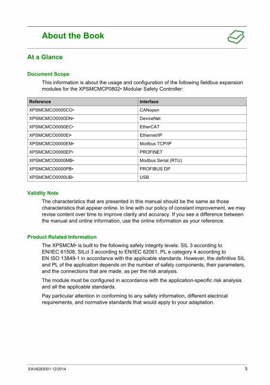
Document Scope
This information is about the usage and configuration of the following fieldbus expansion modules for the XPSMCMCP0802• Modular Safety Controller:
Validity Note
The characteristics that are presented in this manual should be the same as those characteristics that appear online. In line with our policy of constant improvement, we may revise content over time to improve clarity and accuracy. If you see a difference between the manual and online information, use the online information as your reference.
Product Related Information
The XPSMCM• is built to the following safety integrity levels: SIL 3 according to EN/IEC 61508, SILcl 3 according to EN/IEC 62061, PL e category 4 according to EN ISO 13849-1 in accordance with the applicable standards. However, the definitive SIL and PL of the application depends on the number of safety components, their parameters, and the connections that are made, as per the risk analysis.
The module must be configured in accordance with the application-specific risk analysis and all the applicable standards.
Pay particular attention in conforming to any safety information, different electrical requirements, and normative standards that would apply to your adaptation.
Reference Interface
XPSMCMCO0000CO• CANopen
XPSMCMCO0000DN• DeviceNet
XPSMCMCO0000EC• EtherCAT
XPSMCMCO0000EI• Ethernet/IP
XPSMCMCO0000EM• Modbus TCP/IP
XPSMCMCO0000EP• PROFINET
XPSMCMCO0000MB• Modbus Serial (RTU)
XPSMCMCO0000PB• PROFIBUS DP
XPSMCMCO0000UB• USB
EAV8283001 12/2014 5
NOTE: Configuration of the module is the sole responsibility of the installer or user.
For all matters concerning functional safety, if necessary, contact the competent safety authorities or the competent trade associations of your country.
Consult the specific product documentation and the relative product and/or application standards to ensure correct use of modules connected to the fieldbus expansion modules within your specific application.
The ambient temperature of the installed system must be compatible with the operating temperature parameters stated on the product label and in the product specifications.
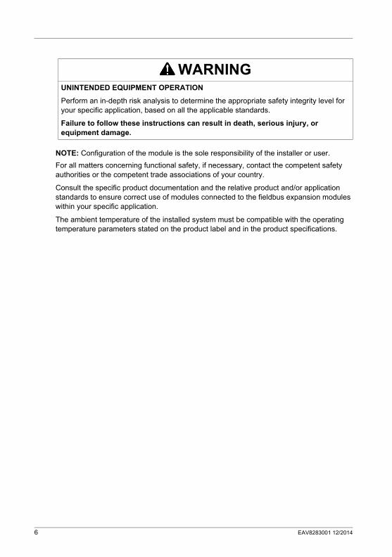
WARNINGUNINTENDED EQUIPMENT OPERATION
Perform an in-depth risk analysis to determine the appropriate safety integrity level for your specific application, based on all the applicable standards.
Failure to follow these instructions can result in death, serious injury, or equipment damage.
6 EAV8283001 12/2014
XPSMCMx Fieldbus Expansion Modules
EAV8283001 12/2014
XPSMCMx Fieldbus Expansion Modules
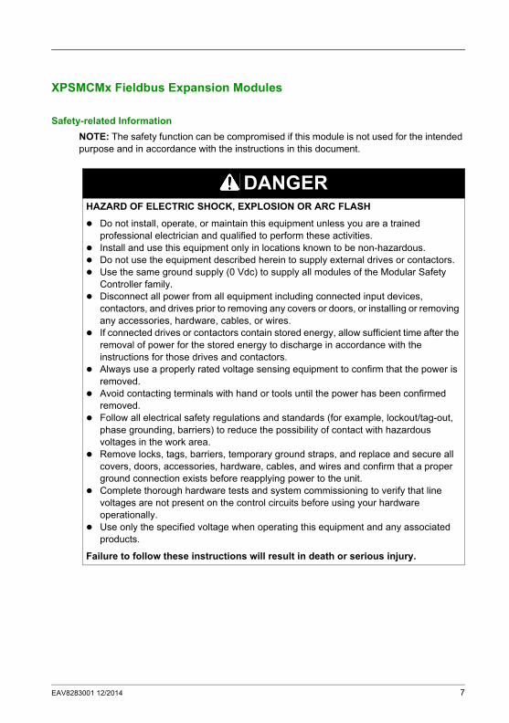
Safety-related Information
NOTE: The safety function can be compromised if this module is not used for the intended purpose and in accordance with the instructions in this document.
DANGERHAZARD OF ELECTRIC SHOCK, EXPLOSION OR ARC FLASH
Do not install, operate, or maintain this equipment unless you are a trained professional electrician and qualified to perform these activities.
Install and use this equipment only in locations known to be non-hazardous. Do not use the equipment described herein to supply external drives or contactors. Use the same ground supply (0 Vdc) to supply all modules of the Modular Safety
Controller family. Disconnect all power from all equipment including connected input devices,
contactors, and drives prior to removing any covers or doors, or installing or removing any accessories, hardware, cables, or wires.
If connected drives or contactors contain stored energy, allow sufficient time after the removal of power for the stored energy to discharge in accordance with the instructions for those drives and contactors.
Always use a properly rated voltage sensing equipment to confirm that the power is removed.
Avoid contacting terminals with hand or tools until the power has been confirmed removed.
Follow all electrical safety regulations and standards (for example, lockout/tag-out, phase grounding, barriers) to reduce the possibility of contact with hazardous voltages in the work area.
Remove locks, tags, barriers, temporary ground straps, and replace and secure all covers, doors, accessories, hardware, cables, and wires and confirm that a proper ground connection exists before reapplying power to the unit.
Complete thorough hardware tests and system commissioning to verify that line voltages are not present on the control circuits before using your hardware operationally.
Use only the specified voltage when operating this equipment and any associated products.
Failure to follow these instructions will result in death or serious injury.
EAV8283001 12/2014 7

NOTE: The observation of operating limits and duty cycles is of particular importance for equipment designed to perform a safety function. If this module has been subjected to electrical, mechanical, or environmental stresses in excess of its stated limits, do not use it.
User Responsibilities
The information provided in this documentation contains general descriptions and/or technical characteristics of the performance of the products contained herein. This documentation is not intended as a substitute for and is not to be used for determining suitability or reliability of these products for specific user applications. It is the duty of any such user, machine builder, or system integrator to perform the appropriate and complete risk analysis, evaluation, and testing of the products with respect to the relevant specific application or use thereof.
DANGERLOSS OF DESIGNATED SAFETY FUNCTION
Install the XPSMCM• Modular Safety Controller in an enclosure with a protection class of at least IP 54.
Always use an isolated power supply (PELV) to help prevent the application of line voltages to control circuitry in the case of short-circuits.
Failure to follow these instructions will result in death or serious injury.
WARNINGUNINTENDED EQUIPMENT OPERATION
Do not use the Modular Safety Controller in locations where explosive atmospheres are suspected, or are confirmed, to exist.
Do not use the Modular Safety Controller on mobile, moveable, or floating systems. Do not use the Modular Safety Controller for life support systems. Do not use the Modular Safety Controller in underground applications.
Failure to follow these instructions can result in death, serious injury, or equipment damage.
WARNINGUNINTENDED EQUIPMENT OPERATION
Do not exceed any of the rated values specified in this document. Immediately cease using and replace any module that has or might have been
subjected to conditions in excess of its rated operating limits.
Failure to follow these instructions can result in death, serious injury, or equipment damage.
8 EAV8283001 12/2014
Neither Schneider Electric nor any of its affiliates or subsidiaries shall be responsible or liable for misuse of the information contained herein. If you have any suggestions for improvements or amendments or have found discrepancies in this publication, notify Schneider Electric. All pertinent safety regulations must be observed when installing and using this product. For reasons of safety and to help ensure compliance with documented system data, only the manufacturer should perform repairs to components.
Qualified Personnel
Electrical equipment should be installed, operated, serviced, and maintained only by qualified personnel. A qualified person is one who has skills and knowledge related to the construction and operation of this electrical equipment and its installation, and has received safety training to recognize and avoid the hazards involved.
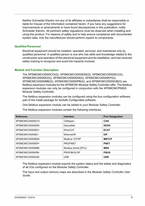
Module and Function Description
The XPSMCMCO0000CO(G), XPSMCMCO0000DN(G), XPSMCMCO0000EC(G), XPSMCMCO0000EI(G), XPSMCMCO0000EM(G), XPSMCMCO0000EP(G), XPSMCMCO0000MB(G), XPSMCMCO0000PB(G), and XPSMCMCO0000UB(G) are fieldbus expansion modules for the XPSMCM• Modular Safety Controller offer. The fieldbus expansion modules can only be configured in conjunction with the XPSMCMCP0802• Modular Safety Controller.
The fieldbus expansion modules can be configured using the bus configuration software, part of the install package for SoSafe Configurable software.
One fieldbus expansion module can be added to your Modular Safety Controller.
The fieldbus expansion modules contain the following interfaces:
The fieldbus expansion module exports the system status and the states and diagnostics of all I/Os configured on the Modular Safety Controller.
The input and output memory maps are described in the Modular Safety Controller User Guide.
Reference Interface Port Designation
XPSMCMCO0000CO• CANopen CAN
XPSMCMCO0000DN• DeviceNet DEVN
XPSMCMCO0000EC• EtherCAT ECAT
XPSMCMCO0000EI• Ethernet/IP EIP
XPSMCMCO0000EM• Modbus TCP/IP MBTCP
XPSMCMCO0000EP• PROFINET PNET
XPSMCMCO0000MB• Modbus Serial (RTU) MBS
XPSMCMCO0000PB• PROFIBUS DP PBUS
XPSMCMCO0000UB• USB USB
EAV8283001 12/2014 9
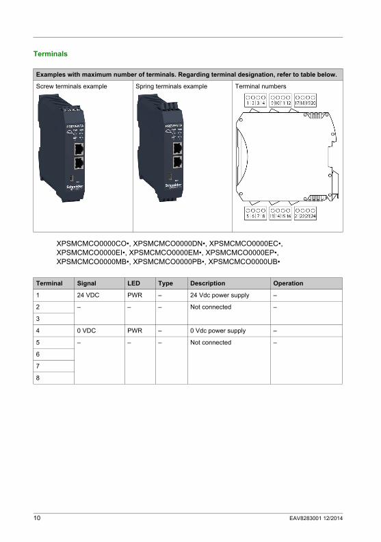
Terminals
XPSMCMCO0000CO•, XPSMCMCO0000DN•, XPSMCMCO0000EC•, XPSMCMCO0000EI•, XPSMCMCO0000EM•, XPSMCMCO0000EP•, XPSMCMCO0000MB•, XPSMCMCO0000PB•, XPSMCMCO0000UB•
Examples with maximum number of terminals. Regarding terminal designation, refer to table below.
Screw terminals example Spring terminals example Terminal numbers
Terminal Signal LED Type Description Operation
1 24 VDC PWR – 24 Vdc power supply –
2 – – – Not connected –
3
4 0 VDC PWR – 0 Vdc power supply –
5 – – – Not connected –
6
7
8
10 EAV8283001 12/2014

Wiring Example
Fieldbus expansion modules
Dimensions
* Screw terminals 108 mm (4.25 in) ** Spring terminals 118 mm (4.67 in) Mount the modules (Modular Safety Controller and any I/O expansion modules) within an IP54 rated
electric cabinet. The minimium clearance below and above the controller is 40 mm. Allow at least 100 mm distance between the cabinet door and the front face of the module(s). There are no clearances required on the left or right side of the module(s); however, other equipment in proximity may require larger distances and those clearances must also be taken into account.
EAV8283001 12/2014 11
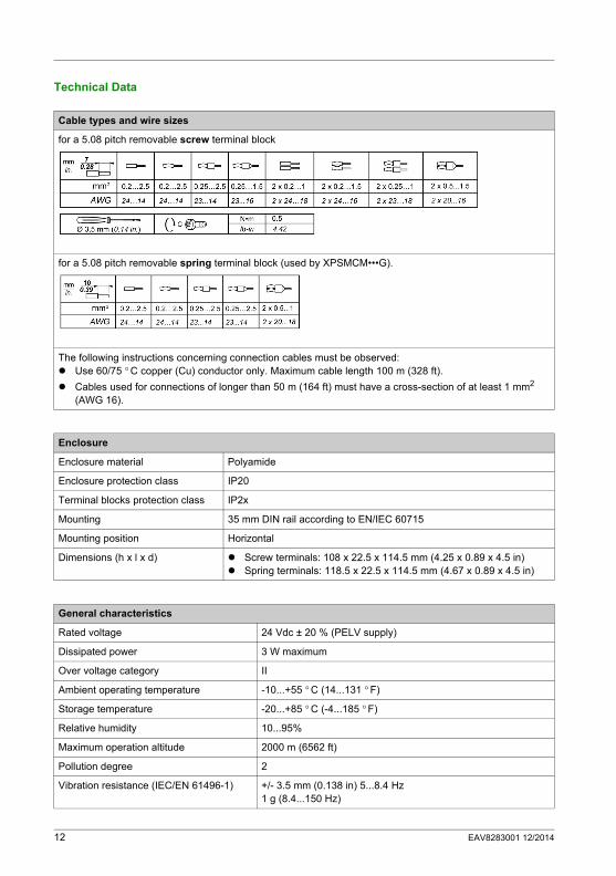
Technical Data
Cable types and wire sizes
for a 5.08 pitch removable screw terminal block
for a 5.08 pitch removable spring terminal block (used by XPSMCM•••G).
The following instructions concerning connection cables must be observed: Use 60/75 ° C copper (Cu) conductor only. Maximum cable length 100 m (328 ft).
Cables used for connections of longer than 50 m (164 ft) must have a cross-section of at least 1 mm2 (AWG 16).
Enclosure
Enclosure material Polyamide
Enclosure protection class IP20
Terminal blocks protection class IP2x
Mounting 35 mm DIN rail according to EN/IEC 60715
Mounting position Horizontal
Dimensions (h x l x d) Screw terminals: 108 x 22.5 x 114.5 mm (4.25 x 0.89 x 4.5 in) Spring terminals: 118.5 x 22.5 x 114.5 mm (4.67 x 0.89 x 4.5 in)
General characteristics
Rated voltage 24 Vdc ± 20 % (PELV supply)
Dissipated power 3 W maximum
Over voltage category II
Ambient operating temperature -10...+55 ° C (14...131 ° F)
Storage temperature -20...+85 ° C (-4...185 ° F)
Relative humidity 10...95%
Maximum operation altitude 2000 m (6562 ft)
Pollution degree 2
Vibration resistance (IEC/EN 61496-1) +/- 3.5 mm (0.138 in) 5...8.4 Hz1 g (8.4...150 Hz)
12 EAV8283001 12/2014
Shock resistance (IEC/EN 61496-1) 15 g (11 ms half-sine)
EMC Category Zone B
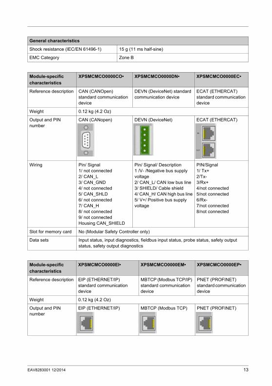
General characteristics
Module-specific
characteristics
XPSMCMCO0000CO• XPSMCMCO0000DN• XPSMCMCO0000EC•
Reference description CAN (CANOpen) standard communication device
DEVN (DeviceNet) standard communication device
ECAT (ETHERCAT) standard communication device
Weight 0.12 kg (4.2 Oz)
Output and PIN number
CAN (CANopen) DEVN (DeviceNet) ECAT (ETHERCAT)
Wiring Pin/ Signal1/ not connected2/ CAN_L3/ CAN_GND4/ not connected5/ CAN_SHLD6/ not connected7/ CAN_H8/ not connected9/ not connectedHousing CAN_SHIELD
Pin/ Signal/ Description1 /V- /Negative bus supply voltage2/ CAN_L/ CAN low bus line3/ SHIELD/ Cable shield4/ CAN_H/ CAN high bus line5/ V+/ Positive bus supply voltage
PIN/Signal1/ Tx+2/Tx-3/Rx+4/not connected5/not connected6/Rx-7/not connected8/not connected
Slot for memory card No (Modular Safety Controller only)
Data sets Input status, input diagnostics, fieldbus input status, probe status, safety output status, safety output diagnostics
Module-specific
characteristics
XPSMCMCO0000EI• XPSMCMCO0000EM• XPSMCMCO0000EP•
Reference description EIP (ETHERNET/IP) standard communication device
MBTCP (Modbus TCP/IP) standard communication device
PNET (PROFINET) standard communication device
Weight 0.12 kg (4.2 Oz)
Output and PIN number
EIP (ETHERNET/IP) MBTCP (Modbus TCP) PNET (PROFINET)
EAV8283001 12/2014 13
Wiring PIN/Signal1/ Tx+2/Tx-3/Rx+4/not connected5/not connected6/Rx-7/not connected8/not connected
Slot for memory card No (Modular Safety Controller only)
Data sets Input status, input diagnostics, fieldbus input status, probe status, safety output status, safety output diagnostics
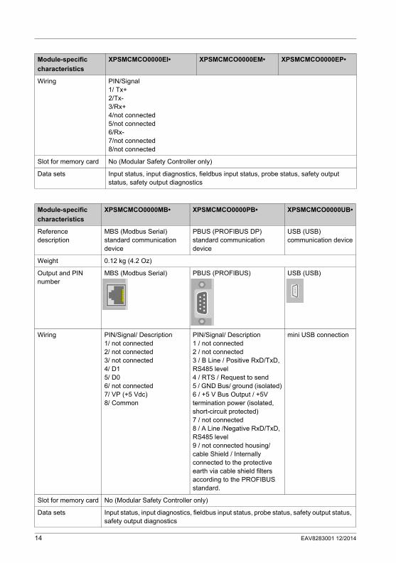
Module-specific
characteristics
XPSMCMCO0000EI• XPSMCMCO0000EM• XPSMCMCO0000EP•
Module-specific
characteristics
XPSMCMCO0000MB• XPSMCMCO0000PB• XPSMCMCO0000UB•
Reference description
MBS (Modbus Serial) standard communication device
PBUS (PROFIBUS DP) standard communication device
USB (USB) communication device
Weight 0.12 kg (4.2 Oz)
Output and PIN number
MBS (Modbus Serial) PBUS (PROFIBUS) USB (USB)
Wiring PIN/Signal/ Description1/ not connected2/ not connected3/ not connected4/ D15/ D06/ not connected7/ VP (+5 Vdc)8/ Common
PIN/Signal/ Description1 / not connected2 / not connected3 / B Line / Positive RxD/TxD, RS485 level4 / RTS / Request to send5 / GND Bus/ ground (isolated)6 / +5 V Bus Output / +5V termination power (isolated, short-circuit protected)7 / not connected8 / A Line /Negative RxD/TxD, RS485 level9 / not connected housing/ cable Shield / Internally connected to the protective earth via cable shield filters according to the PROFIBUS standard.
mini USB connection
Slot for memory card No (Modular Safety Controller only)
Data sets Input status, input diagnostics, fieldbus input status, probe status, safety output status, safety output diagnostics
14 EAV8283001 12/2014
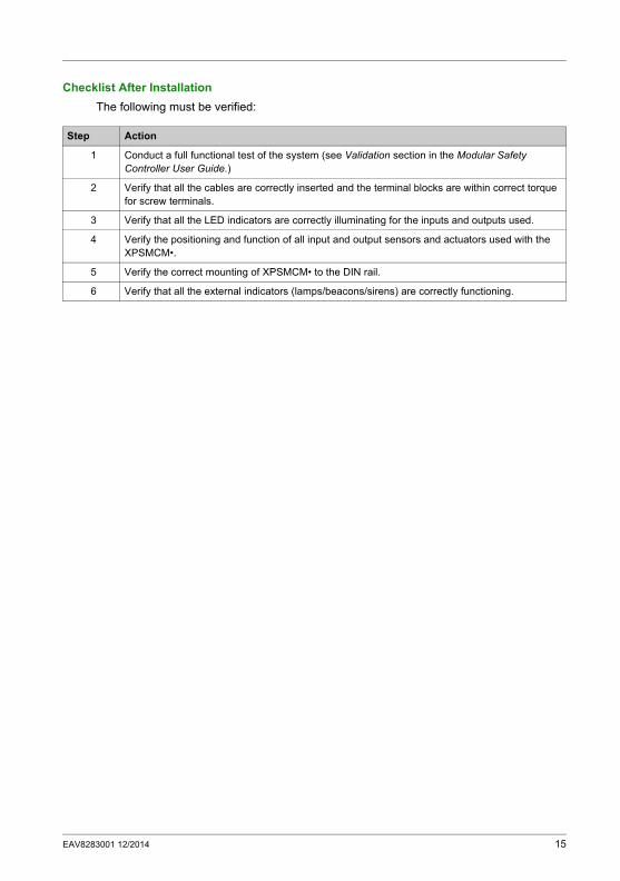
Checklist After Installation
The following must be verified:
Step Action
1 Conduct a full functional test of the system (see Validation section in the Modular Safety Controller User Guide.)
2 Verify that all the cables are correctly inserted and the terminal blocks are within correct torque for screw terminals.
3 Verify that all the LED indicators are correctly illuminating for the inputs and outputs used.
4 Verify the positioning and function of all input and output sensors and actuators used with the XPSMCM•.
5 Verify the correct mounting of XPSMCM• to the DIN rail.
6 Verify that all the external indicators (lamps/beacons/sirens) are correctly functioning.
EAV8283001 12/2014 15
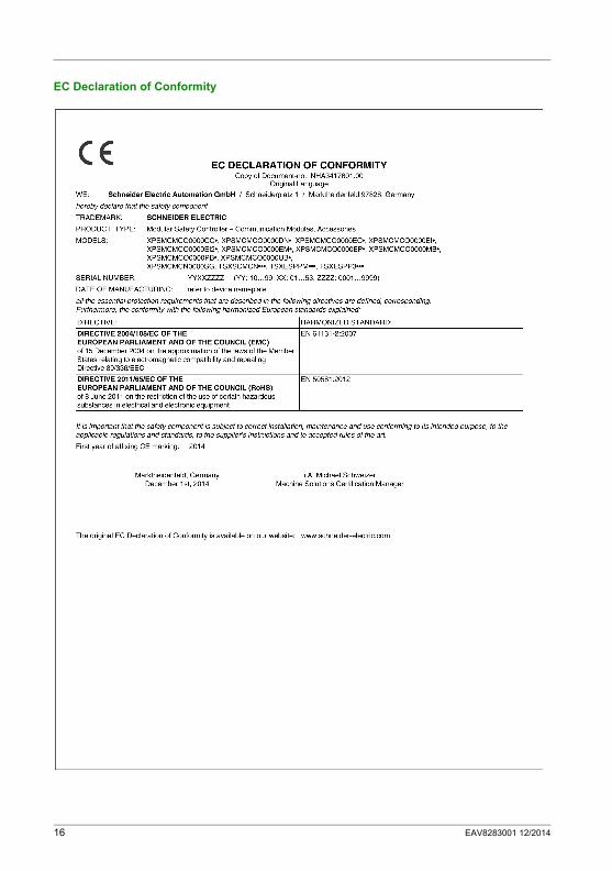
EC Declaration of Conformity
16 EAV8283001 12/2014