Embed Size (px)
Citation preview
XMOS AVB Design Guide
Version 4v0 - Draft
Publication Date: 2009/11/30
Copyright © 2009 XMOS Ltd. All Rights Reserved.
XMOS AVB Design Guide (4v0 - Draft) 2/29
1 Summary
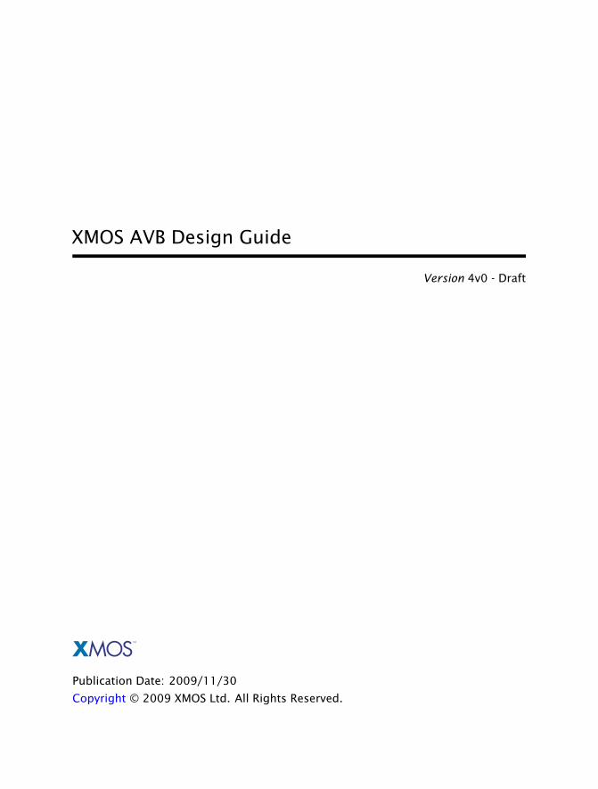
The XMOS Audio Visual Bridging (AVB) reference design can be used to streamsynchronized audio over an ethernet network. The XMOS solution is based on event-driven programmable devices, which can transmit and receive multiple audio streams,and implement both talker and listener functionality.
TALKER TALKER
LISTENERLISTENER
AVBNetwork
Audio Source(I2S, S/PDIF, USB)
Audio Source(I2S, S/PDIF, USB)
Audio Output(I2S, S/PDIF, USB)
Audio Output(I2S, S/PDIF, USB)
XMOSDevice
XMOSDevice
XMOSDevice PHY
PHY
PHY PHY
XMOSDevice
XMOS AVB Features
• Supports all endpoint requirements: ethernet interface, packet processing,timing synchronisation, configuration/stream setup and media rate recoverycan all be handled on device.
• Supports emerging AVB ethernet standards such as IEEE 802.1as, IEEE 801.1Qavand IEEE P1722.
• Flexible software based design implements both hardware interfaces and pro-tocol layers in the same environment allowing, flexibility in system design andeasy modification.
• Multiple audio hardware interfaces supported such as I2S, TDM and S/PDIF.
www.xmos.com
XMOS AVB Design Guide (4v0 - Draft) 3/29
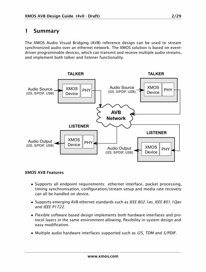
2 XMOS AVB Specification
Functionality
Provides ethernet interface, audio transport, precise timing protocol clocksynchronise and media clock recovery to streamed audio over ethernet.
Supported Standards
Ethernet IEEE 802.3 (via MII)
AVB QoS IEEE 802.1Qav
Precise Timing Protocol IEEE 1588v2 or IEEE 802.1as
AVB Audio Over Ethernet IEEE 1722
Audio Streaming IEC 61883-6
Supported Devices
XMOS Devices XS1-G4
XS1-G2
XS1-L2
Requirements
Development Tools XMOS Desktop Tools v9.9.1 orlater
Ethernet 1 × MII compatible 100Mbit PHY
or
2 × MII compatible 100Mbit PHY
or
1 × GMII compatible Gigabit PHY+ programmable logic device
Audio Audio input/output device (e.g.ADC/DAC audio CODEC)
PLL/Frequency synthesizer chip togenerate CODEC system clock
Boot/Storage Compatible SPI Flash Device
Licensing and Support
Reference code provided under license from XMOS.Contact [email protected] for details.
Reference code is maintained by XMOS Limited.
www.xmos.com
XMOS AVB Design Guide (4v0 - Draft) 4/29
3 Ethernet AVB Standards
Ethernet AVB consists of a collection of different standards that together allowaudio and video to be streamed over ethernet. The standards allow synchronized,uninterrupted streaming with multiple talkers and listeners on a switched networkinfrastructure.
3.1 802.1Qas
802.1Qas defines a precise timing protocol based on the IEEE 1558v2 protocol.It allows every device connected to the network to share a common global clock.The protocol allows devices to have a synchronized view of this clock to withinmicroseconds of each other, aiding media stream clock recovery and coordinatedAVB traffic control.
This protocol is implemented in the XMOS AVB solution.
3.2 802.1Qav
802.1Qav defines a standard for buffering and forwarding of traffic through thenetwork using particular flow control algorithms. It uses the global clock providedby 802.1as to synchronize traffic forwarding and gives predictable latency controlon media streams going through the network.
The XMOS AVB solution implements the requirements for endpoints defined by802.1av. This is done by traffic flow control in the transmit arbiter of the ethernetMAC component.
3.3 802.1Qat
802.1Qat defines a stream reservation protocol that provides end-to-end reservationof bandwidth across an AVB network.
This protocol is not currently implemented in the AVB solution. It could be imple-mented as part of the user application on an XMOS device or by a separate hostprocessor communicating with an XMOS device.
3.4 Emerging standards
3.4.1 IEEE P1722
IEEE P1722 defines an encapsulation protocol to transport audio streams over ether-net. It is complementary to the AVB standards and in particular allows timestamping
www.xmos.com
XMOS AVB Design Guide (4v0 - Draft) 5/29
of a stream based on the 802.1as global clock.
The XMOS AVB solution handles both transmission and receipt of audio streamsusing IEEE P1722. In addition it can use the 802.1as timestamps to accurately recoverthe sample rate clock of the audio to match on the listener side.
3.4.2 IEC 61883-6
IEC 61883-6 defines an audio data format that is contained in IEEE P1722 streams.
The XMOS AVB solution uses IEC 61883-6 to convey audio sample streams.
www.xmos.com
XMOS AVB Design Guide (4v0 - Draft) 6/29
4 XS1 Architecture
The XS1 architecture consists of one or more processing cores, called XCores™,which have the following properties:
• Each XCore can execute up to eight threads concurrently, each at a speed of upto 100 MIPS. Each thread has a dedicated register set enabling it to operate asa logical core.
• The eight threads share a single 64 KByte unified memory with no accesscollisions.
• Integer and fixed point operations are provided for efficient DSP and crypto-graphic operations.
• I/O general purpose pins are provided, which can be programmed from software.Thread execution is deterministic and hence each thread can implement a hardreal-time I/O task, regardless of the behavior of other threads.
• I/O pins are grouped into logical ports of width 1, 4, 8, 16 and 32 bits. Each portincorporates serialization/deserialization, synchronization with the externalinterface and precision timing.
• Each XCore incorporates eight timers that measure time relative to a 100 MHzreference clock.
The architecture is designed to support standard programming languages such as C.Extensions to standard languages, libraries, or the use of assembly language provideaccess to the full benefits of the instruction set.
4.1 XMOS XS1 Programmable Devices
The XS1 family is the first available implementation of the XS1 architecture. Itincludes the XS1-G4 device that integrates four XCore processors. Each device isconnected to a high performance switch interconnect via four internal links calledXMOS Links™. Each link is capable of transferring data at 800 Mbits/second. Theswitch provides full connectivity between the cores on the programmable device, andalso provides up to sixteen external XMOS Links. Each external link is capable oftransferring data at up to 400 Mbits/second.
Other members of the family include the XS1-L1, XS1-G2 and XS1-L2. XS1 devicescan be used standalone, or can be connected together using XMOS Links to create anetwork of XCore processors.
www.xmos.com
XMOS AVB Design Guide (4v0 - Draft) 7/29
4.2 Software Libraries
The XS1 architecture implements hardware as software, so that hardware solutionsare just software libraries. These software solutions are compiled and linked likeordinary C code into a binary file which can be loaded and executed on the device.
The XMOS AVB Reference Software is a library of source files that can be included ina larger application (templates and demos are provided with the reference design).The application can then be compiled and deployed onto a device to provide yourAVB hardware solution.
4.3 XC Language
The XMOS originated XC language [1] is based on C. XC is a concurrent and real-timeprogramming language designed to target the XS1 architecture. XC programs areeasy to write and debug, leading to programs that are free from deadlocks, raceconditions and memory violations and can be compiled to produce high performancemulticore designs.
XC uses channels to provide high-speed bidirectional communication and synchro-nization between channel ends within threads on the same processor, a differentprocessor on the same chip or a different chip.
www.xmos.com
XMOS AVB Design Guide (4v0 - Draft) 8/29
5 XMOS AVB System Description
Audio subsystem(s)
PLL driver
ConfigIP/UDP/TCP
AudioCODEC
PLL
GPIO
PHY
MAC1722talker
1722listener
1722packetrouter
PTPserver
Mediaclockserver
Audiointerface
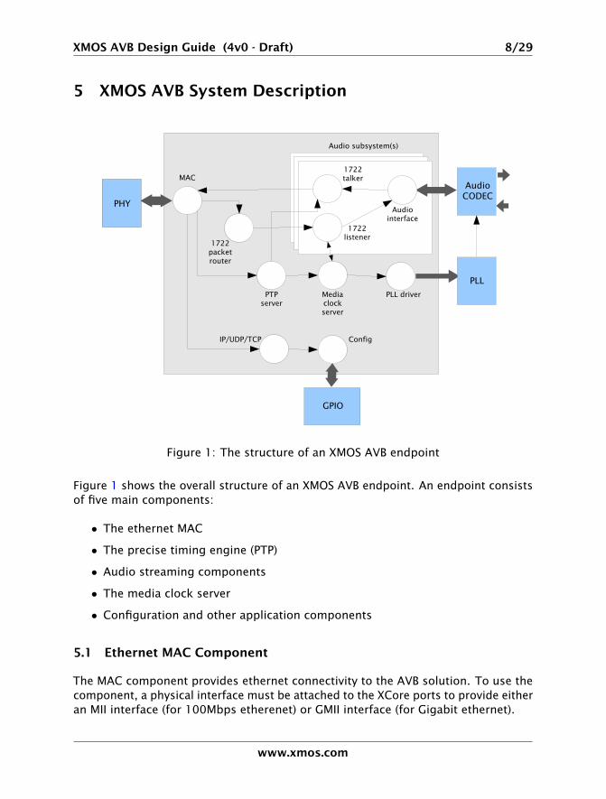
Figure 1: The structure of an XMOS AVB endpoint
Figure 1 shows the overall structure of an XMOS AVB endpoint. An endpoint consistsof five main components:
• The ethernet MAC
• The precise timing engine (PTP)
• Audio streaming components
• The media clock server
• Configuration and other application components
5.1 Ethernet MAC Component
The MAC component provides ethernet connectivity to the AVB solution. To use thecomponent, a physical interface must be attached to the XCore ports to provide eitheran MII interface (for 100Mbps etherenet) or GMII interface (for Gigabit ethernet).
www.xmos.com
XMOS AVB Design Guide (4v0 - Draft) 9/29
The MAC component supports two features that are necessary to implement AVBstandards with precise timing and quality constraints.
• Timestamping - allows receipt and transmission of ethernet frames to betimestamped with respect to a clock (i.e a 100MHz reference clock can providea resolution of 10ns).
• Bandwidth control - allows different channels to have different priorities andbandwidth restrictions to allow steady flow of outgoing media stream packets.The implementation provides flow control to satisfy the requirements of an AVBendpoint as specified in the upcoming 802.1Qav standard.
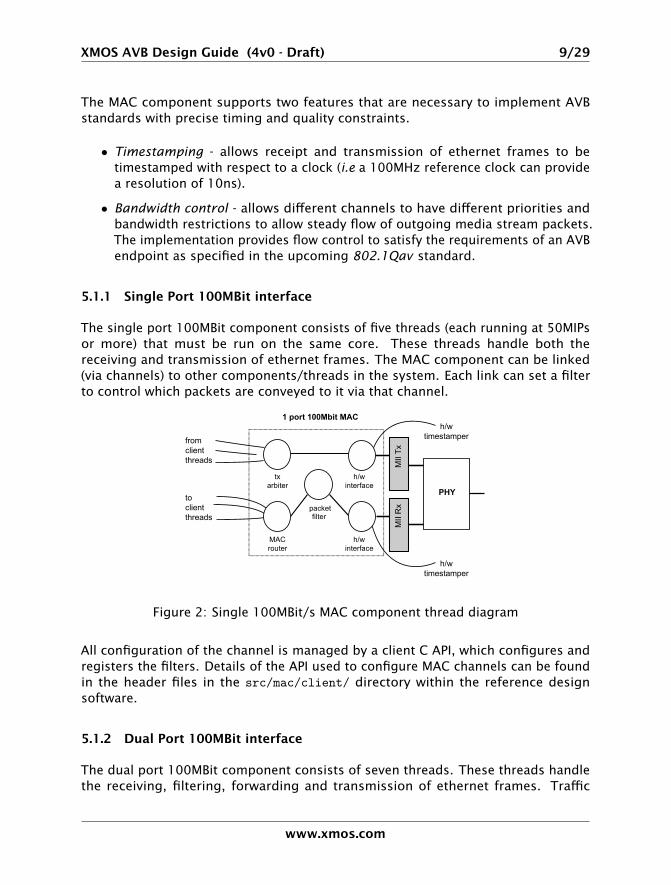
5.1.1 Single Port 100MBit interface
The single port 100MBit component consists of five threads (each running at 50MIPsor more) that must be run on the same core. These threads handle both thereceiving and transmission of ethernet frames. The MAC component can be linked(via channels) to other components/threads in the system. Each link can set a filterto control which packets are conveyed to it via that channel.
from clientthreads
toclientthreads
MACrouter
packetfilter
h/winterface
txarbiter
h/winterface
h/wtimestamper
h/wtimestamper
PHY
1 port 100Mbit MAC
MII
Rx
MII
Tx
Figure 2: Single 100MBit/s MAC component thread diagram
All configuration of the channel is managed by a client C API, which configures andregisters the filters. Details of the API used to configure MAC channels can be foundin the header files in the src/mac/client/ directory within the reference designsoftware.
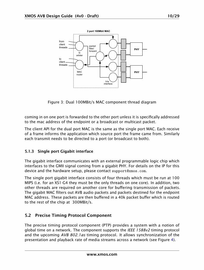
5.1.2 Dual Port 100MBit interface
The dual port 100MBit component consists of seven threads. These threads handlethe receiving, filtering, forwarding and transmission of ethernet frames. Traffic
www.xmos.com
XMOS AVB Design Guide (4v0 - Draft) 10/29
from clientthreads
toclientthreads
MACrouter
packetfilter/forward
h/winterface
txarbiter
2 port 100Mbit MAC
PHY
PHY
Figure 3: Dual 100MBit/s MAC component thread diagram
coming in on one port is forwarded to the other port unless it is specifically addressedto the mac address of the endpoint or a broadcast or multicast packet.
The client API for the dual port MAC is the same as the single port MAC. Each receiveof a frame informs the application which source port the frame came from. Similarlyeach transmit needs to be directed to a port (or broadcast to both).
5.1.3 Single port Gigabit interface
The gigabit interface communicates with an external programmable logic chip whichinterfaces to the GMII signal coming from a gigabit PHY. For details on the IP for thisdevice and the hardware setup, please contact [email protected].
The single port gigabit interface consists of four threads which must be run at 100MIPS (i.e. for an XS1-G4 they must be the only threads on one core). In addition, twoother threads are required on another core for buffering transmission of packets.The gigabit MAC filters out AVB audio packets and packets destined for the endpointMAC address. These packets are then buffered in a 40k packet buffer which is routedto the rest of the chip at 300MBit/s.
5.2 Precise Timing Protocol Component
The precise timing protocol component (PTP) provides a system with a notion ofglobal time on a network. The component supports the IEEE 1588v2 timing protocoland the upcoming AVB 802.1as timing protocol. It allows synchronization of thepresentation and playback rate of media streams across a network (see Figure 4).
www.xmos.com
XMOS AVB Design Guide (4v0 - Draft) 11/29
PTP
To MAC To client threads
PTP packetprocessor
PTP server
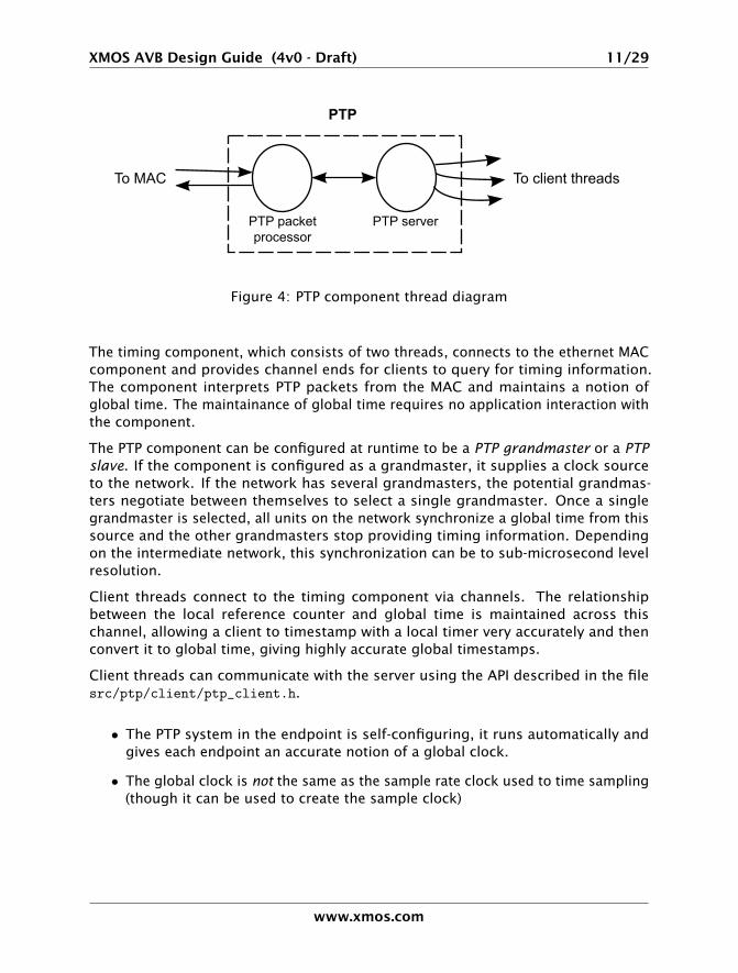
Figure 4: PTP component thread diagram
The timing component, which consists of two threads, connects to the ethernet MACcomponent and provides channel ends for clients to query for timing information.The component interprets PTP packets from the MAC and maintains a notion ofglobal time. The maintainance of global time requires no application interaction withthe component.
The PTP component can be configured at runtime to be a PTP grandmaster or a PTPslave. If the component is configured as a grandmaster, it supplies a clock sourceto the network. If the network has several grandmasters, the potential grandmas-ters negotiate between themselves to select a single grandmaster. Once a singlegrandmaster is selected, all units on the network synchronize a global time from thissource and the other grandmasters stop providing timing information. Dependingon the intermediate network, this synchronization can be to sub-microsecond levelresolution.
Client threads connect to the timing component via channels. The relationshipbetween the local reference counter and global time is maintained across thischannel, allowing a client to timestamp with a local timer very accurately and thenconvert it to global time, giving highly accurate global timestamps.
Client threads can communicate with the server using the API described in the filesrc/ptp/client/ptp_client.h.
• The PTP system in the endpoint is self-configuring, it runs automatically andgives each endpoint an accurate notion of a global clock.
• The global clock is not the same as the sample rate clock used to time sampling(though it can be used to create the sample clock)
www.xmos.com
XMOS AVB Design Guide (4v0 - Draft) 12/29
5.3 Audio Components
5.3.1 AVB Streams, Channels, Talkers and Listeners
Audio is transported in streams of data, where each stream may have multiplechannels. Endpoints producing the streams are called Talkers and those receivingthem are called Listeners. Each stream on the network has a unique 64-bit stream ID.
Routing is done using layer 2 ethernet addresses. Each stream is sent from a partic-ular source MAC address to a particular destination MAC address. The destinationMAC address may be a multicast address (i.e. several Listeners may receive it). Inaddition, AVB switches can reserve an end-to-end path with guaranteed bandwidthfor a stream. This is done by the Talker endpoint advertising the stream to theswitches and the Listener registering to receive it. If sufficient bandwidth is notavailable, this registration may fail.
Streams carry their own presentation time (the time that samples are due to beoutput) allowing multiple Listeners that receive the same stream to output in sync.
• Streams are encoded using the 1722 AVB transport protocol.
• All channels in a stream must be synchronized to the same sample clock.
• All the channels in a stream must come from the same Talker.
• Routing of audio streams uses ethernet layer 2 routing, which can be eitherunicast (one-to-one) or multicast (one-to-many).
• Routing is done at the stream level. All channels within a stream must be routedto the same place. However, a stream can be multicast to several Listeners,each of which picks out different channels.
• A single end point can be both a Talker and Listener.
• The stream ID is the only information you can obtain about a stream beforeregistering to listen to it. Any other information about the stream must becommunicated by a higher level protocol (see Section 5.5).
5.3.2 Internal Routing
As described in the previous section, an IEEE P1722 audio stream may consist ofmany channels. These channels need to be routed to particular audio I/Os on theendpoint. To achieve maximum flexibility the XMOS design uses intermediate localaudio streams to route audio.
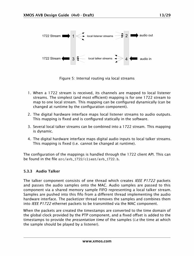
Figure 5 shows the breakdown of 1722 streams into local streams. The Figure showsfour points where transitions to and from local streams occur.
www.xmos.com
XMOS AVB Design Guide (4v0 - Draft) 13/29
local listener streams
local talker streams
1 2
3 4
1722 Stream
1722 Stream
audio out
audio in
Figure 5: Internal routing via local streams
1. When a 1722 stream is received, its channels are mapped to local listenerstreams. The simplest (and most efficient) mapping is for one 1722 stream tomap to one local stream. This mapping can be configured dynamically (can bechanged at runtime by the configuration component).
2. The digital hardware interface maps local listener streams to audio outputs.This mapping is fixed and is configured statically in the software.
3. Several local talker streams can be combined into a 1722 stream. This mappingis dynamic.
4. The digital hardware interface maps digital audio inputs to local talker streams.This mapping is fixed (i.e. cannot be changed at runtime).
The configuration of the mappings is handled through the 1722 client API. This canbe found in the file src/avb_1722/client/avb_1722.h.
5.3.3 Audio Talker
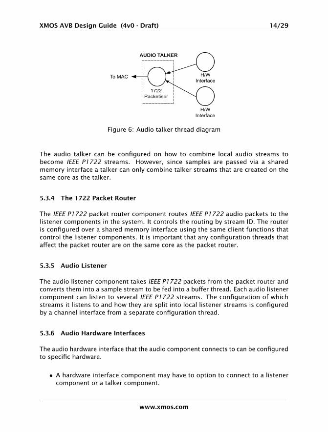
The talker component consists of one thread which creates IEEE P1722 packetsand passes the audio samples onto the MAC. Audio samples are passed to thiscomponent via a shared memory sample FIFO representing a local talker stream.Samples are pushed into this fifo from a different thread implementing the audiohardware interface. The packetizer thread removes the samples and combines theminto IEEE P1722 ethernet packets to be transmitted via the MAC component.
When the packets are created the timestamps are converted to the time domain ofthe global clock provided by the PTP component, and a fixed offset is added to thetimestamps to provide the presentation time of the samples (i.e the time at whichthe sample should be played by a listener).
www.xmos.com
XMOS AVB Design Guide (4v0 - Draft) 14/29
Figure 6: Audio talker thread diagram
The audio talker can be configured on how to combine local audio streams tobecome IEEE P1722 streams. However, since samples are passed via a sharedmemory interface a talker can only combine talker streams that are created on thesame core as the talker.
5.3.4 The 1722 Packet Router
The IEEE P1722 packet router component routes IEEE P1722 audio packets to thelistener components in the system. It controls the routing by stream ID. The routeris configured over a shared memory interface using the same client functions thatcontrol the listener components. It is important that any configuration threads thataffect the packet router are on the same core as the packet router.
5.3.5 Audio Listener
The audio listener component takes IEEE P1722 packets from the packet router andconverts them into a sample stream to be fed into a buffer thread. Each audio listenercomponent can listen to several IEEE P1722 streams. The configuration of whichstreams it listens to and how they are split into local listener streams is configuredby a channel interface from a separate configuration thread.
5.3.6 Audio Hardware Interfaces
The audio hardware interface that the audio component connects to can be configuredto specific hardware.
• A hardware interface component may have to option to connect to a listenercomponent or a talker component.
www.xmos.com
XMOS AVB Design Guide (4v0 - Draft) 15/29
1722 PacketAnalyser
SampleBuffer
From MAC
AUDIO LISTENER
From PTPComponent
Audio H/WInterface
AudioH/W
Clo
ck
H/W ClockGeneration
Audio ClockRecovery
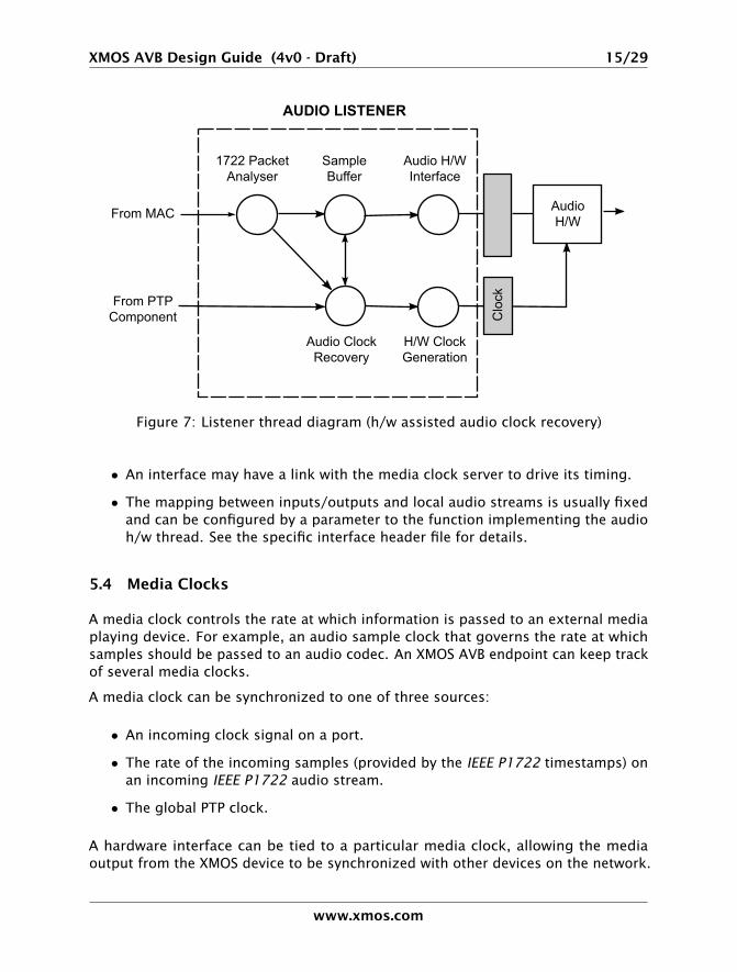
Figure 7: Listener thread diagram (h/w assisted audio clock recovery)
• An interface may have a link with the media clock server to drive its timing.
• The mapping between inputs/outputs and local audio streams is usually fixedand can be configured by a parameter to the function implementing the audioh/w thread. See the specific interface header file for details.
5.4 Media Clocks
A media clock controls the rate at which information is passed to an external mediaplaying device. For example, an audio sample clock that governs the rate at whichsamples should be passed to an audio codec. An XMOS AVB endpoint can keep trackof several media clocks.
A media clock can be synchronized to one of three sources:
• An incoming clock signal on a port.
• The rate of the incoming samples (provided by the IEEE P1722 timestamps) onan incoming IEEE P1722 audio stream.
• The global PTP clock.
A hardware interface can be tied to a particular media clock, allowing the mediaoutput from the XMOS device to be synchronized with other devices on the network.
www.xmos.com
XMOS AVB Design Guide (4v0 - Draft) 16/29
All media clocks are maintained by the media clock server component. This com-ponent takes one thread of processing and maintains the current state of all themedia clocks in the system. It then periodically updates other components with clockchange information to keep the system synchronized. The set of media clocks isdetermined by an array passed to the server at startup.
The media clock server component also receives information from the audio listenercomponent to track timing information of incoming IEEE P1722 streams. It then sendscontrol information back to ensure the listening component honors the presentationtime of the incoming stream.
5.4.1 Driving an external clock generator
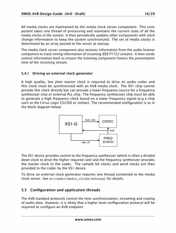
A high quality, low jitter master clock is required to drive an audio codec andthis clock must be synchronized with an AVB media clock. The XS1 chip cannotprovide this clock directly but can provide a lower frequency source for a frequencysynthesizer chip or external PLL chip. The frequency synthesizer chip must be ableto generate a high frequency clock based on a lower frequency signal (e.g a chipsuch as the Cirrus Logic CS2300 or similar). The recommended configuration is as inthe block diagram below:
XS1-G CODECbclk, lrclk
rate, ctl
mclk
FREQSYNTH
The XS1 device provides control to the frequency synthesizer (which is often a divideddown clock to drive the higher required rate) and the frequency synthesizer providesthe master clock to the codec. The sample bit clocks and word clocks are thenprovided to the codec by the XS1 device.
To drive an external clock generator requires one thread connected to the mediaclock server. See src/audio/media_clocks/external for details.
5.5 Configuration and application threads
The AVB standard protocols control the time synchronization, streaming and routingof audio data. However, it is likely that a higher level configuration protocol will berequired to configure an AVB endpoint.
www.xmos.com
XMOS AVB Design Guide (4v0 - Draft) 17/29
Such a protocol needs two parts: discovery and control. The discovery part mustdetermine higher level information about other endpoints on the network. Forexample:
• Discover which other Talkers/Listeners are on the network
• Discover which streams are available and meta-information about them (samplerate, description, global clock synchronization participation etc.)
The control part controls the device. For example it controls:
• The streams the Talker outputs/Listener inputs.
• Audio input/output (sample rate, gain, dsp etc.)
• Other non-audio aspects.
The AVB software solution includes a port of the uIP protocol stack which is asmall memory footprint stack that can be used for UDP/TCP communication to aidimplementation of an upper layer configuration protocol. Future software updates willinclude an implementation of Zeroconf standards (IP link local addressing, multicastDNS and DNS service discovery) to aid in initialisation and discovery. These librarieswill aid in supporting configuration protocols such as the forth-coming 1722.1 AVBstandard.
www.xmos.com
XMOS AVB Design Guide (4v0 - Draft) 18/29
6 System/Application Design
6.1 XMOS AVB Endpoint Capability
An XMOS AVB endpoint provides the ability to take IEEE 1722 audio streams fromethernet and output the audio data.
The number of audio channels the device can handle depends on the XMOS deviceused. The XS1 platform is very flexible and can provide other functions alongsideaudio (depending on how much audio is used) - this includes DSP functionality,controlling inputs and displays on a device or controlling non-AVB ethernet commu-nication.
The amount of audio available for the XS1-G4 and XS1-G2 devices is detailed in thefollowing sections. See Section 10 for more information on chip resource usage andhow these figures were determined. Please note that in a final application the exactcapability depends on the type of digital audio interface, the mapping between 1722and local streams, the complexity of the routing etc. and these figures are meantonly as a rough guide.
• The maximum channel count figures assume that more than two channels areused per AVB stream to maximize channel count.
• The maximum channel count assumes I2S or similar (e.g you cannot get maxi-mum number of channels if all are S/PDIF).
• At 100MBit/s, the capability on the XS1 for higher bit-rates are bounded bybandwidth and buffering in line with the AVB standard.
• For very high channel counts, it is assumed that a multi-channel multiplexed1-wire protocol (e.g. TDM) is used to reduce the required pin count.
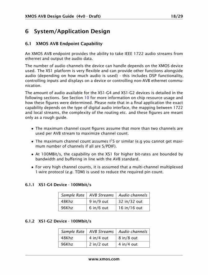
6.1.1 XS1-G4 Device - 100Mbit/s
Sample Rate AVB Streams Audio channels
48Khz 9 in/9 out 32 in/32 out
96Khz 6 in/6 out 16 in/16 out
6.1.2 XS1-G2 Device - 100Mbit/s
Sample Rate AVB Streams Audio channels
48Khz 4 in/4 out 8 in/8 out
96Khz 2 in/2 out 4 in/4 out
www.xmos.com
XMOS AVB Design Guide (4v0 - Draft) 19/29
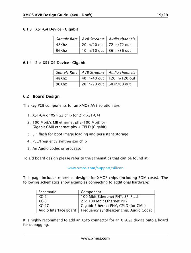
6.1.3 XS1-G4 Device - Gigabit
Sample Rate AVB Streams Audio channels
48Khz 20 in/20 out 72 in/72 out
96Khz 10 in/10 out 36 in/36 out
6.1.4 2 × XS1-G4 Device - Gigabit
Sample Rate AVB Streams Audio channels
48Khz 40 in/40 out 120 in/120 out
96Khz 20 in/20 out 60 in/60 out
6.2 Board Design
The key PCB components for an XMOS AVB solution are:
1. XS1-G4 or XS1-G2 chip (or 2 × XS1-G4)
2. 100 Mbit/s MII ethernet phy (100 Mbit) orGigabit GMII ethernet phy + CPLD (Gigabit)
3. SPI flash for boot image loading and persistent storage
4. PLL/frequency synthesizer chip
5. An Audio codec or processor
To aid board design please refer to the schematics that can be found at:
www.xmos.com/support/silicon
This page includes reference designs for XMOS chips (including BOM costs). Thefollowing schematics show examples connecting to additional hardware:
Schematic ComponentXC-2 100 Mbit Etherenet PHY, SPI FlashXC-3 2 × 100 Mbit Ethernet PHYXC-2G Gigabit Ethernet PHY, CPLD (for GMII)Audio Interface Board Frequency synthesizer chip, Audio Codec
It is highly recommend to add an XSYS connector for an XTAG2 device onto a boardfor debugging.
www.xmos.com
XMOS AVB Design Guide (4v0 - Draft) 20/29
6.3 Software Configuration/Design
Adapting the reference software to a particular application involves:
1. Adding specific functionality (configuration, dsp etc.)
2. Creating a top-level main function to run the required components.
3. Adapting compile time configuration parameters in avb_conf.h.
One of the most important aspects of the specific functionality is the configurationlayer (see Section 5.5).
The top-level main determines which components run on which cores and theirconfiguration (including the port mapping to specific hardware). The best way tocreate a top-level is to copy and adapt one of the demos. Instructions on how tocreate your own application files and build them can be found in the README in thesrc directory of the reference software.
6.4 Firmware upgrading
Every part of the XMOS AVB solution is implemented in software. This gives greatflexibility for field upgrades. Firmware can be upgraded over ethernet. A forthcominglibrary from XMOS will help provide secure firmware upgrades storing boot imageson a standard SPI flash chip. These boot images can be transferred to the device viaethernet over an application specific protocol.
www.xmos.com
XMOS AVB Design Guide (4v0 - Draft) 21/29
7 Licensing and Support Information
7.1 Reference Software License
The XMOS AVB Reference Software is distributed under license from XMOS. Forinformation about licensing please contact XMOS.
7.2 Support
The reference design is maintained by XMOS and is provided “as is” under the termsdescribed in Section 7.1. For details of priority support agreements and pricingplease contact XMOS. Any bugs and/or enhancement requests may be reported witha support ticket at www.xmos.com/support.
www.xmos.com
XMOS AVB Design Guide (4v0 - Draft) 22/29
8 XMOS AVB Software Reference
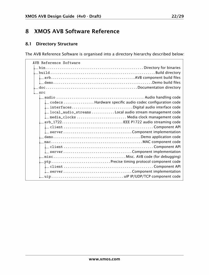
8.1 Directory Structure
The AVB Reference Software is organised into a directory hierarchy described below:
AVB Reference Softwarebin...................................................Directory for binariesbuild.......................................................Build directory
avb............................................AVB component build filesdemo....................................................Demo build files
doc................................................Documentation directorysrc
audio .............................................. Audio handling codecodecs................Hardware specific audio codec configuration codeinterfaces................................Digital audio interface codelocal_audio_streams............Local audio stream management codemedia_clocks ..........................Media clock management code
avb_1722................................IEEE P1722 audio streaming codeclient...............................................Component APIserver....................................Component implementation
demo..............................................Demo application codemac................................................MAC component code
client...............................................Component APIserver....................................Component implementation
misc......................................Misc. AVB code (for debugging)ptp...............................Precise timing protocol component code
client...............................................Component APIserver....................................Component implementation
uip......................................uIP IP/UDP/TCP component code
www.xmos.com
XMOS AVB Design Guide (4v0 - Draft) 23/29
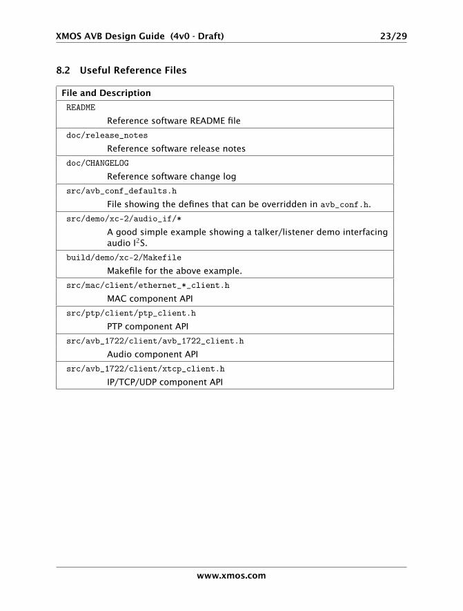
8.2 Useful Reference Files
File and Description
README
Reference software README file
doc/release_notes
Reference software release notes
doc/CHANGELOG
Reference software change log
src/avb_conf_defaults.h
File showing the defines that can be overridden in avb_conf.h.
src/demo/xc-2/audio_if/*
A good simple example showing a talker/listener demo interfacingaudio I2S.
build/demo/xc-2/Makefile
Makefile for the above example.
src/mac/client/ethernet_*_client.h
MAC component API
src/ptp/client/ptp_client.h
PTP component API
src/avb_1722/client/avb_1722_client.h
Audio component API
src/avb_1722/client/xtcp_client.h
IP/TCP/UDP component API
www.xmos.com
XMOS AVB Design Guide (4v0 - Draft) 24/29
9 Bandwidth Requirements
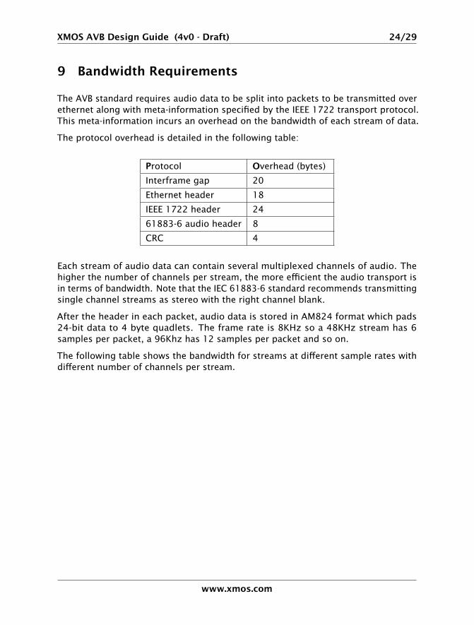
The AVB standard requires audio data to be split into packets to be transmitted overethernet along with meta-information specified by the IEEE 1722 transport protocol.This meta-information incurs an overhead on the bandwidth of each stream of data.
The protocol overhead is detailed in the following table:
Protocol Overhead (bytes)
Interframe gap 20
Ethernet header 18
IEEE 1722 header 24
61883-6 audio header 8
CRC 4
Each stream of audio data can contain several multiplexed channels of audio. Thehigher the number of channels per stream, the more efficient the audio transport isin terms of bandwidth. Note that the IEC 61883-6 standard recommends transmittingsingle channel streams as stereo with the right channel blank.
After the header in each packet, audio data is stored in AM824 format which pads24-bit data to 4 byte quadlets. The frame rate is 8KHz so a 48KHz stream has 6samples per packet, a 96Khz has 12 samples per packet and so on.
The following table shows the bandwidth for streams at different sample rates withdifferent number of channels per stream.
www.xmos.com

XMOS AVB Design Guide (4v0 - Draft) 25/29
Sample Rate Channels/Stream Mbps
48KHz 1 7.81
48KHz 2 7.81
48KHz 4 10.88
48KHz 8 17.02
48KHz 16 29.31
48KHz 32 53.89
96KHz 1 10.88
96KHz 2 10.88
96KHz 4 17.02
96KHz 8 29.31
96KHz 16 53.89
192KHz 1 17.02
192KHz 2 17.02
192KHz 4 29.31
192KHz 8 53.89
Note that the higher the number of channels per stream, the better the bandwidthusage (e.g. 4 × 8 channels streams uses less bandwidth than 16 × 2 channelstreams). The IEEE 1722 standard also specifies that only 75% of available bandwidthcan be used for traffic.
www.xmos.com
XMOS AVB Design Guide (4v0 - Draft) 26/29
10 Chip Resource Usage
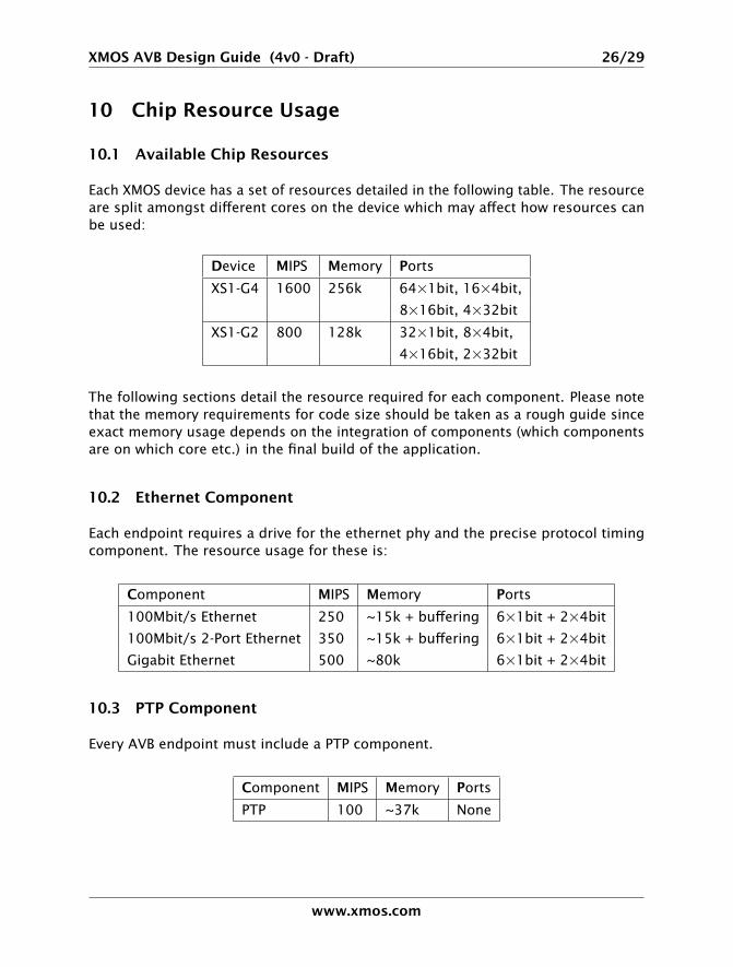
10.1 Available Chip Resources
Each XMOS device has a set of resources detailed in the following table. The resourceare split amongst different cores on the device which may affect how resources canbe used:
Device MIPS Memory Ports
XS1-G4 1600 256k 64×1bit, 16×4bit,
8×16bit, 4×32bit
XS1-G2 800 128k 32×1bit, 8×4bit,
4×16bit, 2×32bit
The following sections detail the resource required for each component. Please notethat the memory requirements for code size should be taken as a rough guide sinceexact memory usage depends on the integration of components (which componentsare on which core etc.) in the final build of the application.
10.2 Ethernet Component
Each endpoint requires a drive for the ethernet phy and the precise protocol timingcomponent. The resource usage for these is:
Component MIPS Memory Ports
100Mbit/s Ethernet 250 ~15k + buffering 6×1bit + 2×4bit
100Mbit/s 2-Port Ethernet 350 ~15k + buffering 6×1bit + 2×4bit
Gigabit Ethernet 500 ~80k 6×1bit + 2×4bit
10.3 PTP Component
Every AVB endpoint must include a PTP component.
Component MIPS Memory Ports
PTP 100 ~37k None
www.xmos.com
XMOS AVB Design Guide (4v0 - Draft) 27/29
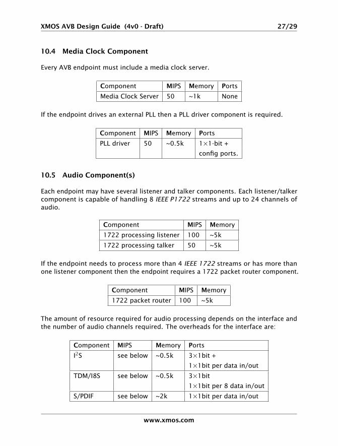
10.4 Media Clock Component
Every AVB endpoint must include a media clock server.
Component MIPS Memory Ports
Media Clock Server 50 ~1k None
If the endpoint drives an external PLL then a PLL driver component is required.
Component MIPS Memory Ports
PLL driver 50 ~0.5k 1×1-bit +
config ports.
10.5 Audio Component(s)
Each endpoint may have several listener and talker components. Each listener/talkercomponent is capable of handling 8 IEEE P1722 streams and up to 24 channels ofaudio.
Component MIPS Memory
1722 processing listener 100 ~5k
1722 processing talker 50 ~5k
If the endpoint needs to process more than 4 IEEE 1722 streams or has more thanone listener component then the endpoint requires a 1722 packet router component.
Component MIPS Memory
1722 packet router 100 ~5k
The amount of resource required for audio processing depends on the interface andthe number of audio channels required. The overheads for the interface are:
Component MIPS Memory Ports
I2S see below ~0.5k 3×1bit +
1×1bit per data in/out
TDM/I8S see below ~0.5k 3×1bit
1×1bit per 8 data in/out
S/PDIF see below ~2k 1×1bit per data in/out
www.xmos.com
XMOS AVB Design Guide (4v0 - Draft) 28/29
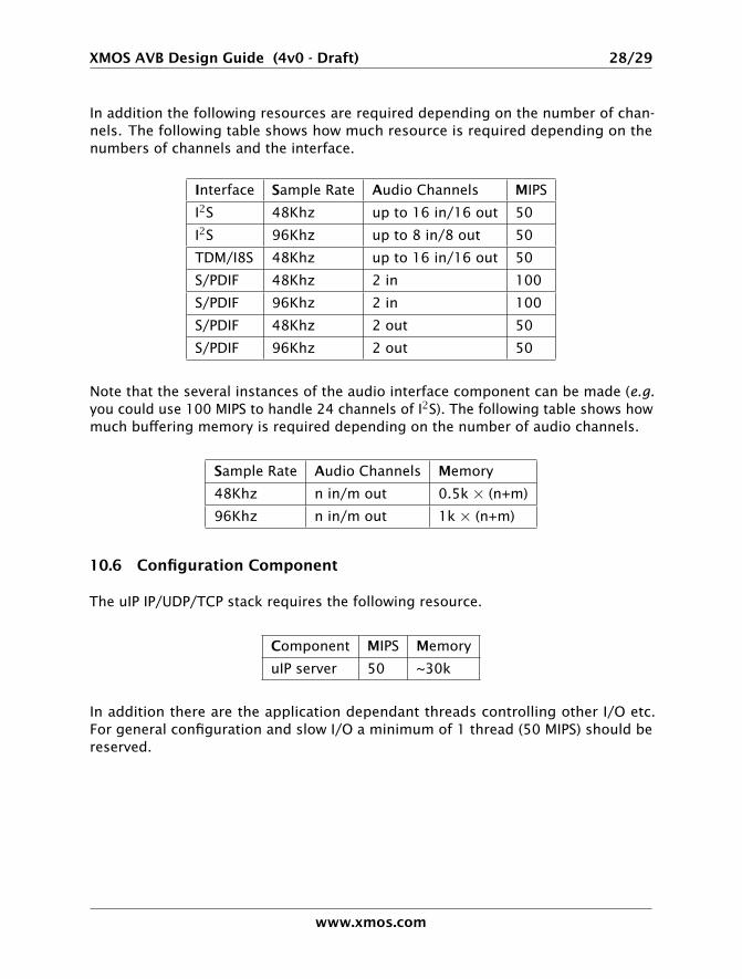
In addition the following resources are required depending on the number of chan-nels. The following table shows how much resource is required depending on thenumbers of channels and the interface.
Interface Sample Rate Audio Channels MIPS
I2S 48Khz up to 16 in/16 out 50
I2S 96Khz up to 8 in/8 out 50
TDM/I8S 48Khz up to 16 in/16 out 50
S/PDIF 48Khz 2 in 100
S/PDIF 96Khz 2 in 100
S/PDIF 48Khz 2 out 50
S/PDIF 96Khz 2 out 50
Note that the several instances of the audio interface component can be made (e.g.you could use 100 MIPS to handle 24 channels of I2S). The following table shows howmuch buffering memory is required depending on the number of audio channels.
Sample Rate Audio Channels Memory
48Khz n in/m out 0.5k × (n+m)
96Khz n in/m out 1k × (n+m)
10.6 Configuration Component
The uIP IP/UDP/TCP stack requires the following resource.
Component MIPS Memory
uIP server 50 ~30k
In addition there are the application dependant threads controlling other I/O etc.For general configuration and slow I/O a minimum of 1 thread (50 MIPS) should bereserved.
www.xmos.com
XMOS AVB Design Guide (4v0 - Draft) 29/29
Bibliography
[1] Douglas Watt and Richard Osborne and David May. XC Reference Manual (8.7).Website, 2008. http://www.xmos.com/published/xc87.
Disclaimer
XMOS Ltd. is the owner or licensee of this design, code, or Information (collectively,the “Information”) and is providing it to you “AS IS” with no warranty of any kind,express or implied and shall have no liability in relation to its use. XMOS Ltd. makesno representation that the Information, or any particular implementation thereof, isor will be free from any claims of infringement and again, shall have no liability inrelation to any such claims.
Copyright ©2009 XMOS Ltd. All Rights Reserved. XMOS and the XMOS logo areregistered trademarks of XMOS Ltd in the United Kingdom and other countries,and may not be used without written permission. Company and product namesmentioned in this document are the trademarks or registered trademarks of theirrespective owners. Where those designations appear in this document, and XMOSwas aware of a trademark claim, the designations have been printed with initialcapital letters or in all capitals.
www.xmos.com