Embed Size (px)
Citation preview
Xilinx ISE tutorial for FPGA Board
CMPE 415
Spring 2017 – Dr. Tinoosh Mohsenin.

1. Creating a New Project. (File>New Project). Give it a project name, select the project location
and click on next.
2. Select your necessary setting for the board you are using and click on Next.
3. You can always change the settings of the project if you select something wrong while creating
the project.4. Click on “Finish” and a New Project will be made.
5. Now right click on the Project > New Source.

6. Select Verilog Module, give it a file name and click on Next, in the next window click finish.
7. Write your Verilog code in the Verilog source that you have created. There is a Counter LED code at the end of the document in the Appendix-I for reference.
8. Add a New Source. This time, add the Implementation Constraint file > give it a name > click next
> then finish.
9. There is a sample ucf file for reference in Appendix-II.

10. Now Synthesize and implement the program by doing the following steps. Click on the Verilog
file first. Then click on Run.
11. Make sure everything runs without errors. After everything runs without errors a new window
opens. All the green marks show the program has run without the errors.
12. Creating a Testbench based on the Verilog module

a. Click on Project > New Source
b. Select Verilog Test Fixture, and name the file as “your_design_tb /
your_design_testbench” and click Next.
c. Choose the source, with which you want to associate the new source.
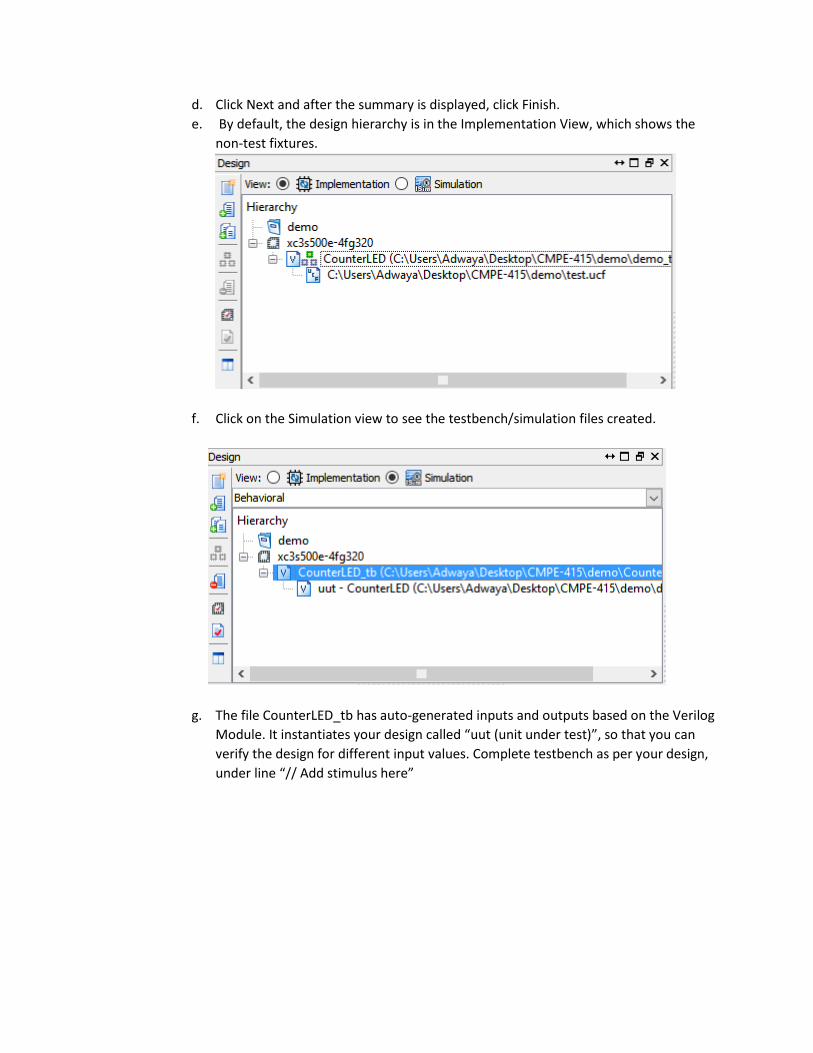
d. Click Next and after the summary is displayed, click Finish.
e. By default, the design hierarchy is in the Implementation View, which shows the
non-test fixtures.
f. Click on the Simulation view to see the testbench/simulation files created.
g. The file CounterLED_tb has auto-generated inputs and outputs based on the Verilog
Module. It instantiates your design called “uut (unit under test)”, so that you can
verify the design for different input values. Complete testbench as per your design,
under line “// Add stimulus here”

h. Run a Behavioral Check Syntax to have error-free code before simulating the
behavioral model.

i. Complete Testbench and click on the Simulate Behavioral Model, to verify the
design. This stage pops-up the ISim waveform debugger, where you can always
verify the design and its intended functionality.
13. Once the Verilog Module is simulated and you can see the desired output in the waveform, the
next step would be to deploy the design onto the FPGA board.
14. Now connect the FPGA board, Go back to the Project Navigator window (first window where
you did the synthesis in step 10), Double click on “Manage Configuration Project”
15. This pops-up another window ISE impact, here double click on “Boundary Scan” > Next right
click on the empty white space as shown in the Fig above and click on Initialize chain. (If any
crash happens here please look into Appendix-III for fixing this issue)

16. Now right click on the component and select “Program device”.

17. The device will Programmed and you will be able to see the blinking led’s as shown in the Image
Below.

Appendix-I
CounterLED Program.
`timescale 1ns / 1ps ////////////////////////////////////////////////////////////////////////////////// // Company: EEHPC // Engineer: Amey Kulkarni // Create Date: 11:16:47 01/21/2012 // Design Name: // Module Name: CounterLED // Project Name: // Target Devices: Spartan 3E and Artix-7 ( This is suppose to work for any board testing !!!) // Tool versions: // Description: I just created for Board testing. You can find ucf file and bit file in this folder ////////////////////////////////////////////////////////////////////////////////// module CounterLED(clk,rst,countOut1,countOut2,countOut3); input clk,rst; output countOut1,countOut2,countOut3; reg count1,count2,count3; reg [27:0]countTemp; assign countOut1=count1; assign countOut2=count2; assign countOut3=count3; always@(posedge clk) if(rst) begin countTemp<=32'd0; count1<=1'b0; count2<=1'b0; count3<=1'b0; end else if(countTemp==27'b000_1111_1111_1111_1111_1111_1111) begin // countTemp<=32'd0; count1<=count1+1'b1; countTemp<=countTemp+1'b1; end else if (countTemp==27'b011_1111_1111_1111_1111_1111_1111) begin count2<=count2+1'b1; countTemp<=countTemp+1'b1; end else if (countTemp==27'b111_1111_1111_1111_1111_1111_1111)

begin count3<=count3+1'b1; countTemp<=countTemp+1'b1; end else begin countTemp<=countTemp+1'b1; end endmodule
Appendix-II
Ucf file for LED Counter Verilog code.
#//////////////////////////////////////////////////////////////////////////////// # Company: EEHPC # Engineer: Amey Kulkarni # Create Date: 11:16:47 01/21/2012 # Design Name: # Module Name: CounterLED # Project Name: # Target Devices: Spartan 3E and Artix-7 ( This is suppose to work for any board testing !!!) # Uncomment Constraints based on the Boards # Tool versions: # Description: I just created for Board testing. You can find ucf file and bit file in this folder #//////////////////////////////////////////////////////////////////////////////// # Spartan 3E # Family: Spartan 3E, Device: xc3s500e Package : FG320, Speed : -4 #NET "countOut1" LOC = "E11" | IOSTANDARD = LVTTL | SLEW = SLOW | DRIVE = 8 ; #NET "countOut2" LOC = "E12" | IOSTANDARD = LVTTL | SLEW = SLOW | DRIVE = 8 ; #NET "countOut3" LOC = "F12" | IOSTANDARD = LVTTL | SLEW = SLOW | DRIVE = 8 ; # #NET "rst" LOC = "L13" | IOSTANDARD = LVTTL | PULLUP ; #NET "clk" LOC = "C9" | IOSTANDARD = LVCMOS33 ; # Artix-7 - Nexys Video Constraint File # Family : Artix-7 , Device : xc7a200t, Package : SBG484 , Speed : -1 NET "countOut1" LOC = "T14" | IOSTANDARD = LVTTL | SLEW = SLOW | DRIVE = 8 ; NET "countOut2" LOC = "T15" | IOSTANDARD = LVTTL | SLEW = SLOW | DRIVE = 8 ; NET "countOut3" LOC = "T16" | IOSTANDARD = LVTTL | SLEW = SLOW | DRIVE = 8 ; NET "rst" LOC = "E22" | IOSTANDARD = LVTTL | PULLUP ; NET "clk" LOC = "R4" | IOSTANDARD = LVCMOS33 ;
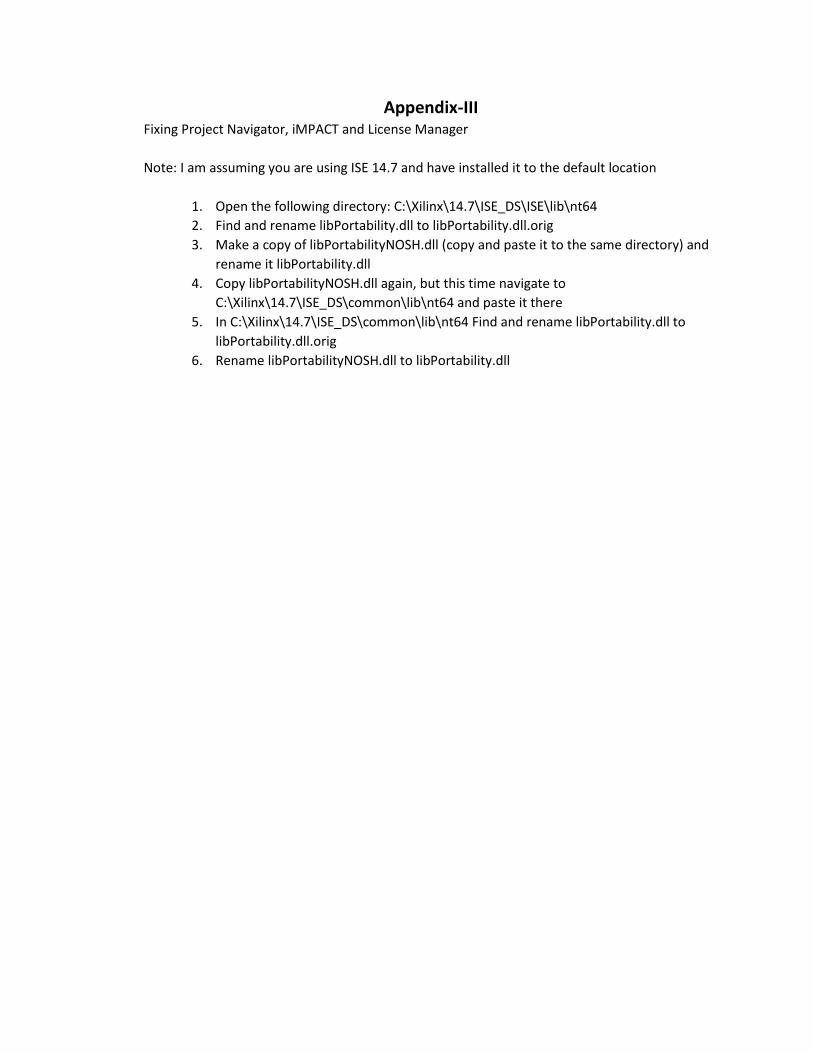
Appendix-III Fixing Project Navigator, iMPACT and License Manager
Note: I am assuming you are using ISE 14.7 and have installed it to the default location
1. Open the following directory: C:\Xilinx\14.7\ISE_DS\ISE\lib\nt64
2. Find and rename libPortability.dll to libPortability.dll.orig
3. Make a copy of libPortabilityNOSH.dll (copy and paste it to the same directory) and
rename it libPortability.dll
4. Copy libPortabilityNOSH.dll again, but this time navigate to
C:\Xilinx\14.7\ISE_DS\common\lib\nt64 and paste it there
5. In C:\Xilinx\14.7\ISE_DS\common\lib\nt64 Find and rename libPortability.dll to
libPortability.dll.orig
6. Rename libPortabilityNOSH.dll to libPortability.dll