Embed Size (px)
Citation preview
Order toll-free in the U.S. Call 877-877-BBOX (outside U.S. call 724-746-5500)FREE technical support, 24 hours a day, 7 days a week: Call 724-746-5500 or fax 724-746-0746Mailing address: Black Box Corporation, 1000 Park Drive, Lawrence, PA 15055-1018Web site: www.blackbox.com • E-mail: [email protected]
CUSTOMER SUPPORT
INFORMATION
MARCH 1999MX321A-232-R3 MX321AE-232-R3 MX321A-232-D48-R2MX321A-35-R2 MX321AE-35-R2 MX321A-35-D48-R2MX321A-36-R2 MX321AE-36-R2MX321A-530-R2 MX321AE-X21-R3
X.25 PAD-8
POWER
MAIN
SYNC ERR OFF TEST
RESETX.25 PAD-8
1 2 3 4 5 6 7 8
1 2 3 4 5 6 7 8

EMI/RFI AND SAFETY STATEMENTS
1
FEDERAL COMMUNICATIONS COMMISSION, INDUSTRY CANADA, AND EUROPEAN UNIONRADIO-FREQUENCY INTERFERENCE AND ELECTRICAL-SAFETY STATEMENTS
This equipment generates, uses, and can radiate radio frequency energy and if not installed and used properly, that is, in strict accordance with the manufacturer’s instructions, may cause interference to radiocommunication. It has been tested and found to comply with the limits for a Class A computing device inaccordance with the specifications in Subpart J of Part 15 of FCC rules, which are designed to providereasonable protection against such interference when the equipment is operated in a commercialenvironment. Operation of this equipment in a residential area is likely to cause interference, in which case the user at his own expense will be required to take whatever measures may be necessary to correct the interference.
Changes or modifications not expressly approved by the party responsible for compliance could void the user’sauthority to operate the equipment.
This digital apparatus does not exceed the Class A limits for radio noise emission from digital apparatus set out in IndustryCanada’s Radio Interference Regulation.
Le présent appareil numérique n’émet pas de bruits radioélectriques dépassant les limites applicables aux appareils numériquesde la classe A prescrites dans le Règlement sur le brouillage radioélectrique publié par Industrie Canada.
The X.25 PAD-8 conforms to the following standards of the European Union:
EMC: EN 55022 (1994) Limits and methods of measurement of radio disturbance characteristics of information technology equipment.
EN 50082-1 (1992) Electromagnetic compatibility—Generic immunity standards for residential, commercial, and light industry.
Safety: EN 60950 (1992/93) Safety of information technology equipment, including electrical business equipment.
The safety status of each of the ports on the X.25 PAD-8 is hereby declared according to EN 41003:
Safety Status PortsSELV 530, V.24, V.35, V.36, X.21, LANTNV-1 ISDN, 4W, DDS
SELV = Safety Extra-Low VoltageTNV-1 = Telecommunications Network Voltage within SELV limits and subject to overvoltages
X.25 PAD-8
2
INSTRUCCIONES DE SEGURIDAD (Normas Oficiales Mexicanas Electrical Safety Statement)1. Todas las instrucciones de seguridad y operación deberán ser leídas antes de que el aparato eléctrico sea operado.
2. Las instrucciones de seguridad y operación deberán ser guardadas para referencia futura.
3. Todas las advertencias en el aparato eléctrico y en sus instrucciones de operación deben ser respetadas.
4. Todas las instrucciones de operación y uso deben ser seguidas.
5. El aparato eléctrico no deberá ser usado cerca del agua—por ejemplo, cerca de la tina de baño, lavabo, sótanomojado o cerca de una alberca, etc..
6. El aparato eléctrico debe ser usado únicamente con carritos o pedestales que sean recomendados por el fabricante.
7. El aparato eléctrico debe ser montado a la pared o al techo sólo como sea recomendado por el fabricante.
8. Servicio—El usuario no debe intentar dar servicio al equipo eléctrico más allá a lo descrito en las instrucciones deoperación. Todo otro servicio deberá ser referido a personal de servicio calificado.
9. El aparato eléctrico debe ser situado de tal manera que su posición no interfiera su uso. La colocación del aparatoeléctrico sobre una cama, sofá, alfombra o superficie similar puede bloquea la ventilación, no se debe colocar enlibreros o gabinetes que impidan el flujo de aire por los orificios de ventilación.
10. El equipo eléctrico deber ser situado fuera del alcance de fuentes de calor como radiadores, registros de calor, estufasu otros aparatos (incluyendo amplificadores) que producen calor.
11. El aparato eléctrico deberá ser connectado a una fuente de poder sólo del tipo descrito en el instructivo deoperación, o como se indique en el aparato.
12. Precaución debe ser tomada de tal manera que la tierra fisica y la polarización del equipo no sea eliminada.
13. Los cables de la fuente de poder deben ser guiados de tal manera que no sean pisados ni pellizcados por objetoscolocados sobre o contra ellos, poniendo particular atención a los contactos y receptáculos donde salen del aparato.
14. El equipo eléctrico debe ser limpiado únicamente de acuerdo a las recomendaciones del fabricante.
15. En caso de existir, una antena externa deberá ser localizada lejos de las lineas de energia.
16. El cable de corriente deberá ser desconectado del cuando el equipo no sea usado por un largo periodo de tiempo.
17. Cuidado debe ser tomado de tal manera que objectos liquidos no sean derramados sobre la cubierta u orificios deventilación.
18. Servicio por personal calificado deberá ser provisto cuando:
A: El cable de poder o el contacto ha sido dañado; u
B: Objectos han caído o líquido ha sido derramado dentro del aparato; o
C: El aparato ha sido expuesto a la lluvia; o
D: El aparato parece no operar normalmente o muestra un cambio en su desempeño; o
E: El aparato ha sido tirado o su cubierta ha sido dañada.
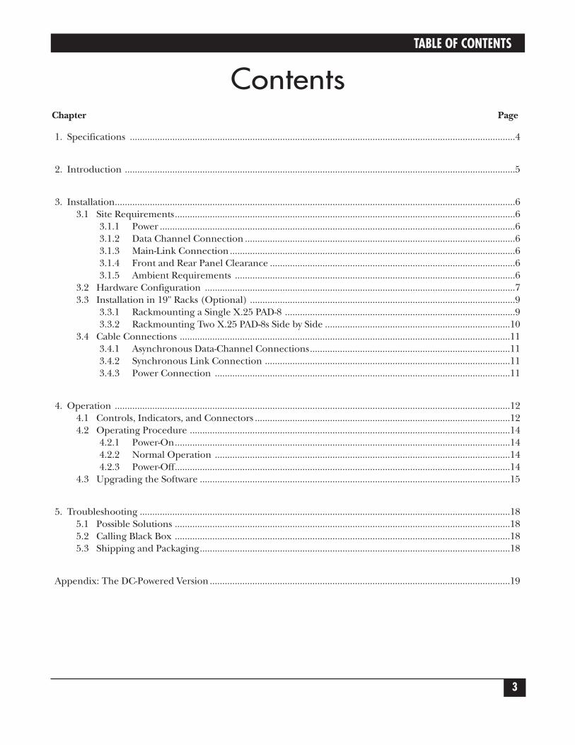
TABLE OF CONTENTS
3
ContentsChapter Page
1. Specifications ..........................................................................................................................................................4
2. Introduction ............................................................................................................................................................5
3. Installation................................................................................................................................................................63.1 Site Requirements........................................................................................................................................6
3.1.1 Power ..............................................................................................................................................63.1.2 Data Channel Connection ............................................................................................................63.1.3 Main-Link Connection ..................................................................................................................63.1.4 Front and Rear Panel Clearance ..................................................................................................63.1.5 Ambient Requirements ................................................................................................................6
3.2 Hardware Configuration ............................................................................................................................73.3 Installation in 19" Racks (Optional) ..........................................................................................................9
3.3.1 Rackmounting a Single X.25 PAD-8 ............................................................................................93.3.2 Rackmounting Two X.25 PAD-8s Side by Side ..........................................................................10
3.4 Cable Connections ....................................................................................................................................113.4.1 Asynchronous Data-Channel Connections................................................................................113.4.2 Synchronous Link Connection ..................................................................................................113.4.3 Power Connection ......................................................................................................................11
4. Operation ..............................................................................................................................................................124.1 Controls, Indicators, and Connectors ......................................................................................................124.2 Operating Procedure ................................................................................................................................14
4.2.1 Power-On......................................................................................................................................144.2.2 Normal Operation ......................................................................................................................144.2.3 Power-Off......................................................................................................................................14
4.3 Upgrading the Software ............................................................................................................................15
5. Troubleshooting ....................................................................................................................................................185.1 Possible Solutions ......................................................................................................................................185.2 Calling Black Box ......................................................................................................................................185.3 Shipping and Packaging............................................................................................................................18
Appendix: The DC-Powered Version ........................................................................................................................19

X.25 PAD-8
4
1. SpecificationsGENERAL
Indicators— (14) Front-mounted LEDs: (1) Power, (1) Main-link activity, (8) Sub-channelactivity, (1) Loss of synchronization, (1) Error, (1) Overflow, (1) Test
Packet Size— Up to 4096 bytes for X.25; up to 8192 bytes for other protocols
Throughput— 500 packets per second
Memory— 512 KB RAM
SYNCHRONOUS LINK
Interface and Connector— (1) port for all models:“-232” models: EIA/TIA RS-232/ITU-T V.24, DCE or DTE (DB25 female);“-35” models: ITU-T V.35, DCE or DTE (M/34 female);“-36” models: EIA/TIA RS-530/ITU-T V.36, DTE (DB25 female);“-X21” models: ITU-T X.21, DTE (DB15 female)
Data Rate— Up to 2 Mbps
Clock Source— External clocking for receive and transmit paths; internal clock for DCEinterfaces
ASYNCHRONOUS CHANNELS
Interface and Connectors— RS-232/V.24, DCE, proprietarily pinned on (8) RJ-45 female connectors
Data Rate— 75 bps to 115.2 kbps, programmable
Flow Control— XON/XOFF or RTS/CTS flow control, user-selectable
Channel Log-On Messages— Herald and bulletin, user-definable
Command Modes— ITU-T Rec. X.28 and proprietary extensions, ITU-T Rec. X.29
Terminal Handling— Enhanced, handling beyond ITU-T Rec. X.3 requirements
POWER
Supply Voltage— “A” models: 115 VAC, 50/60 Hz;“AE” models: 230 VAC, 50/60 Hz;“A-D48” models: +24, –24, +48, or –48 VDC
Consumption— 15 W
Fuse— 125 mA, 250 V
ENVIRONMENT
Temperature— 32 to 122°F (0 to 50°C)
Humidity— Up to 90%, noncondensing
PHYSICAL
Size— 1.7"H x 8.5"W x 9.5"D (4.3 x 21.6 x 24.1 cm)
Weight— 3.9 lb. (1.8 kg)

CHAPTER 2: Introduction
5
2. IntroductionThe X.25 PAD-8 provides easy, cost-effective access to a packet-switching network.
The X.25 PAD-8 has one synchronous port, which supports data rates up to 2 Mbps. The synchronous port canbe configured to either X.25 or Frame Relay. The port’s interface can be V.24, V.35, X.21, or RS-530. InterfacesV.24 and V.35 for the port can be either DCE or DTE layer 1 (depending on the model you order). Otherinterfaces are available; call Technical Support for more information.
The X.25 PAD-8 can connect up to eight asynchronous channels. The asynchronous channels can beconfigured as X.28 or SLIP and operate at data rates up to 115.2 kbps.
X.25 PAD-8
6
3. InstallationThe X.25 PAD-8 is delivered completely assembled. It can be installed as a desktop unit or mounted in a 19-inchrack. After installing the unit, see the Packet Switching Guide for instructions about configuring, operating,testing, and troubleshooting it.
3.1 Site Requirements
3.1.1 POWER
If your X.25 PAD-8 is an AC-powered model, install it within 5 feet (1.5 m) of an easily accessible grounded ACoutlet that supplies the appropriate voltage (115 or 230 VAC, depending on the model you ordered) for yourPAD-8. If your X.25 PAD-8 is a DC-powered mode, see the Appendix.
3.1.2 DATA-CHANNEL CONNECTIONS
The X.25 PAD-8 has eight RJ-45 connectors—one for each asynchronous data channel. The Packet SwitchingGuide provides pin allocations for these connectors.
3.1.3 MAIN-LINK CONNECTION
What type of main-link connector the X.25 PAD-8 has depends on which interface you ordered for it:
• RS-232/V24: DB25 female
• X.21: DB15 female
• V.35: M/34 (34-pin M-block) female
• RS-530: DB25 female
The Packet Switching Guide provides the pin allocations for these connectors.
3.1.4 FRONT- AND REAR-PANEL CLEARANCE
If the X.25 PAD-8 is installed in a 19-inch rack, leave at least 36 inches (91.4 cm) of frontal clearance foroperator access. Leave at least 4 inches (10.2 cm) clearance at the rear of the unit for interface-cableconnections.
3.1.5 AMBIENT REQUIREMENTS
Operate the X.25 PAD-8 in an area where the temperature does not exceed the range from 32 to 122°F (0 to 50°C) and the relative humidity does not exceed 90% (noncondensing).

CHAPTER 3: Installation
7
3.2 Hardware Configuration
CAUTION!To avoid the danger of an electrical shock, always turn the power switch off anddisconnect the power cable from the power source before opening the X.25 PAD-8.
As shown in Figure 3-1 below, the X.25 PAD-8 has one main circuit board which contains:
• (2) jumpers for hardware configuration of the X.25 PAD-8.
• A 68302 CPU that runs the X.25 PAD-8 software.
• FLASH memory that receives downloaded software from a connected terminal.
This section describes the functions of the internal jumpers, and provides step-by-step jumper-settinginstructions. The default settings for each jumper are also listed. (After installation, you’ll configure the X.25 PAD-8 with its command facility only. For more information, see the Packet Switching Guide.)
NOTEThe default settings of the X.25 PAD-8 jumpers are suitable for most applications. If your requirementsare different, set the jumpers in accordance with your requirements before you install the X.25 PAD-8.
Figure 3-1. X.25 PAD-8 components.
MAIN BOARD
COVER
CPU68302OCTAL
UART
FLASH
X.25 PAD-8
8
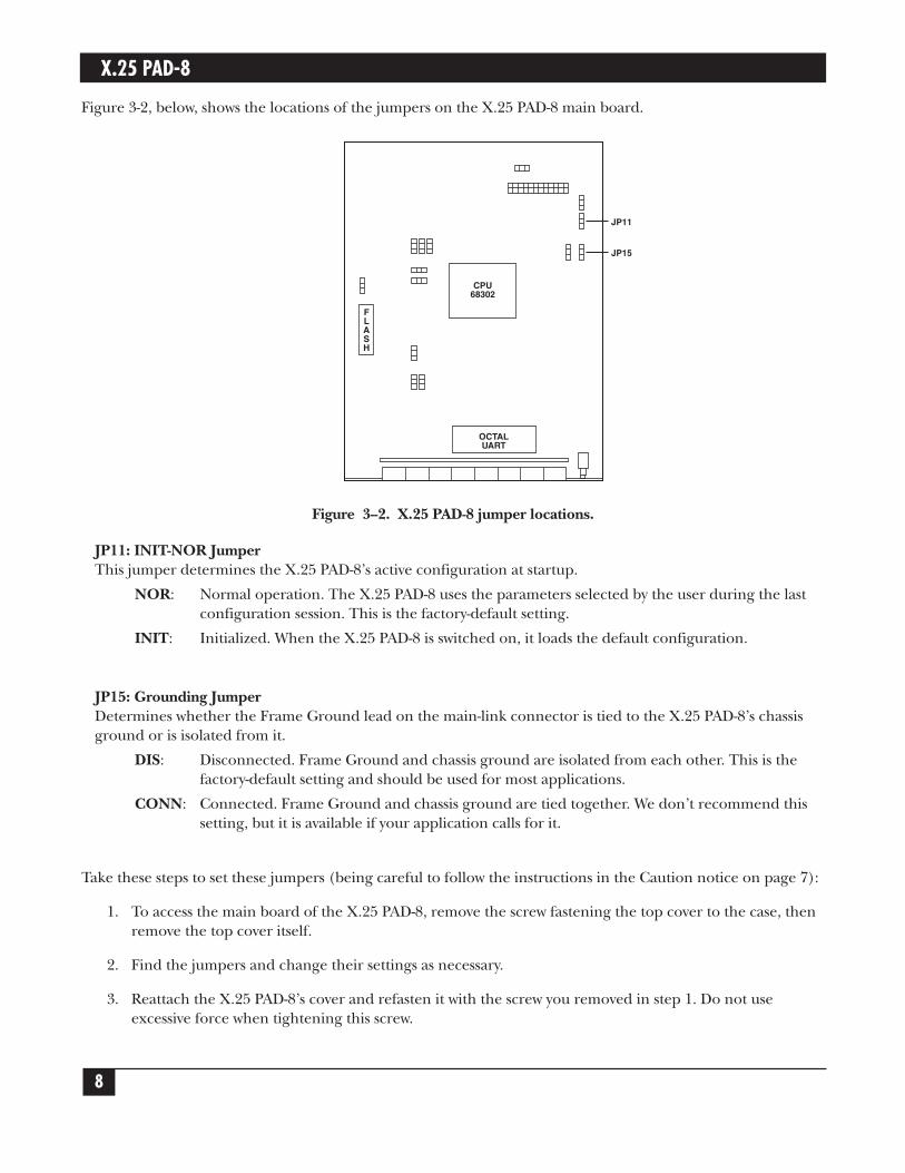
Figure 3-2, below, shows the locations of the jumpers on the X.25 PAD-8 main board.
Figure 3--2. X.25 PAD-8 jumper locations.
JP11: INIT-NOR JumperThis jumper determines the X.25 PAD-8’s active configuration at startup.
NOR: Normal operation. The X.25 PAD-8 uses the parameters selected by the user during the last configuration session. This is the factory-default setting.
INIT: Initialized. When the X.25 PAD-8 is switched on, it loads the default configuration.
JP15: Grounding JumperDetermines whether the Frame Ground lead on the main-link connector is tied to the X.25 PAD-8’s chassis ground or is isolated from it.
DIS: Disconnected. Frame Ground and chassis ground are isolated from each other. This is the factory-default setting and should be used for most applications.
CONN: Connected. Frame Ground and chassis ground are tied together. We don’t recommend this setting, but it is available if your application calls for it.
Take these steps to set these jumpers (being careful to follow the instructions in the Caution notice on page 7):
1. To access the main board of the X.25 PAD-8, remove the screw fastening the top cover to the case, thenremove the top cover itself.
2. Find the jumpers and change their settings as necessary.
3. Reattach the X.25 PAD-8’s cover and refasten it with the screw you removed in step 1. Do not useexcessive force when tightening this screw.
JP11
CPU68302
FLASH
OCTALUART
JP15
CHAPTER 3: Installation
9
3.3 Installation in 19" Racks (Optional)The X.25 PAD-8 can be installed in 19" racks. The X.25 PAD-8 height corresponds to 1U (1.75"). The width of the X.25 PAD-8 is slightly less than the available mounting width.
A rackmount kit (part number RM516) is available for the X.25 PAD-8. It includes two short brackets, a longbracket, two small U-brackets, and a set of eight screws and washers. This means that you can use it to installeither a single device or two devices side by side; all the necessary hardware is included in the kit either way.
CAUTION!Disconnect the units from AC power before performing the following procedures.
3.3.1 RACKMOUNTING A SINGLE X.25 PAD-8
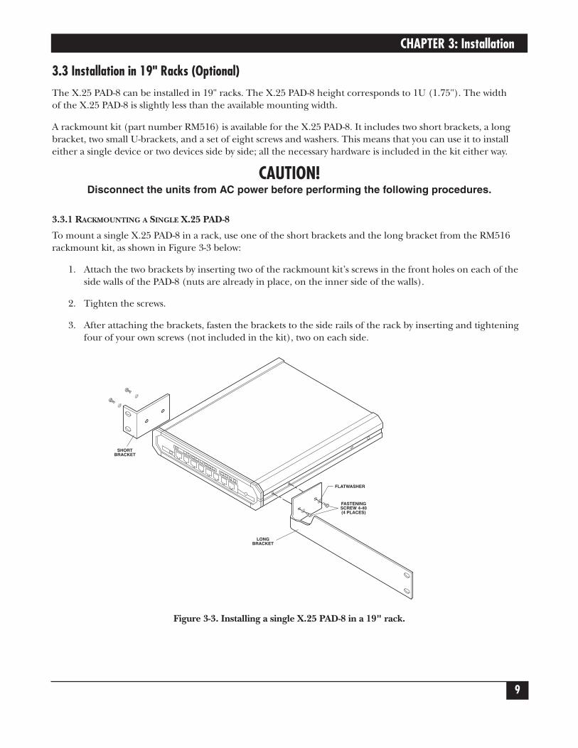
To mount a single X.25 PAD-8 in a rack, use one of the short brackets and the long bracket from the RM516rackmount kit, as shown in Figure 3-3 below:
1. Attach the two brackets by inserting two of the rackmount kit’s screws in the front holes on each of theside walls of the PAD-8 (nuts are already in place, on the inner side of the walls).
2. Tighten the screws.
3. After attaching the brackets, fasten the brackets to the side rails of the rack by inserting and tighteningfour of your own screws (not included in the kit), two on each side.
Figure 3-3. Installing a single X.25 PAD-8 in a 19" rack.
SHORTBRACKET
LONGBRACKET
FLATWASHER
FASTENINGSCREW 4-40(4 PLACES)

X.25 PAD-8
10
3.3.2 RACKMOUNTING TWO X.25 PAD-8S SIDE BY SIDE
To mount two X.25 PAD-8s in a rack side by side, use both of the short brackets and the U-brackets from theRM516 rackmount kit, as shown in Figure 3-4 below:
1. Remove the cover (1) from the PAD-8 that will sit on the right side of the rack.
2. Position one of the two U-brackets (2) over the slots inside of the inner left wall of the PAD-8. Align theU-bracket’s holes with the holes in the device wall.
3. Place flat washers (3A) over two long screws (3B). Insert the screws through the U-bracket into the holesin the PAD-8’s side wall.
4. Repeat steps 2 and 3 for the other U-bracket.
5. Hold the second PAD-8 close to the left wall of the first PAD-8. Tighten the four screws (one turn at atime for each) so that their ends emerge from the left wall and engage the holes in the right wall of thesecond PAD-8. Continue tightening the screws until their heads rest against the U-brackets and the twoPAD-8s are in contact.
6. Reassemble the cover on the first PAD-8.
7. Using four short screws (7B) and flat washers (7C), fasten one adapter bracket (7A) to the outer wall of each PAD-8.
8. Using four of your own screws, two on each side (not included in the kit), fasten the two PAD-8s to theside rails of the 19" rack.
Figure 3-4. Installing two X.25 PAD-8s in a 19" rack.
FLATWASHER(4 PLACES)
SHORTBRACKET
SHORTBRACKET
U BRACKET(2 PLACES)
COVER
ADAPTERBRACKET
(7A)
LONG SCREW (4 PLACES)
FLATWASHER (7C)(4 PLACES)
SHORT SCREW (7B)(4 PLACSE)
PUSHTOGETHER

CHAPTER 3: Installation
11
3.4 Cable ConnectionsThe X.25 PAD-8 has one connector on the rear panel that serves the synchronous link, and eight RJ-45connectors on the front panel for the asynchronous data channels.
3.4.1 ASYNCHRONOUS DATA-CHANNEL CONNECTIONS
X.25 PAD-8 channel interfaces are configured as DCE interfaces, thereby allowing direct connection, throughRS-232 cables, to DTE. If modems are used to extend the range (creating tail-end circuits), crossover cables arerequired. Channel interfaces are asynchronous, so clock signals are not supported or required.
The Packet Switching Guide lists the pin allocation for the X.25 PAD-8’s data-channel connectors, and alsoprovides typical wiring diagrams for straight-through and crossover cables.
3.4.2 SYNCHRONOUS LINK CONNECTION
Depending on which model of the X.25 PAD-8 you ordered, the synchronous link will be carried on one of these interfaces/connectors (always pinned out as DTE):
• RS-232/V24, DB25 female
• X.21, DB15 female
• V.35, M/34 female
• RS-530, DB25 female
The Packet Switching Guide lists the pin allocations for these link connectors.
NOTEThe user data cables and the synchronous link cables should be shielded, in order to comply with FCCrules. The X.25 PAD-8 and its data interfaces will work well even if the cables are not shielded, but someradio interference may occur.
3.4.3 POWER CONNECTION
AC power is supplied to the AC-powered versions of the X.25 PAD-8 through a 5-foot (1.5-m) power cordterminated by a standard 3-prong plug. Run this cord from the IEC 320 male power inlet on the PAD-8 to astandard grounded AC power outlet. (For details about connecting power to the DC-powered versions of thePAD-8, see the Appendix.)
WARNING!The X.25 PAD-8 unit should always be grounded through the protective earth lead ofthe power cord. To connect AC power to this unit, the mains plug should only beinserted into a socket outlet provided with protective earth contact. The protectiveaction must not be negated by use of an extension cord without a groundingconductor.
Whenever it is likely that the unit’s fuse (located in a bayonet-type fuse holder onthe unit’s rear panel) has been blown or damaged, make the unit inoperative andsecure it against unintended operation until the fuse can be replaced. Make sure thatonly fuses of the required rating, as marked on the rear panel, are used forreplacement. Do not use repaired fuses or short-circuit the fuse holder. Alwaysdisconnect the mains cable before removing or replacing the fuse.
Interrupting the grounding conductor, inside or outside the unit, or disconnectingthe protective earth contact, can make this unit dangerous!
X.25 PAD-8
12
4. OperationThe X.25 PAD-8 supports a wide range of applications. For example, it can function as any of these things:
• An access unit to X.25 private or public networks.
• An access server to X.25 ports of mainframes.
• A FRAD to run asynchronous data in X.25 packets over Frame Relay.
• A FRAD to run asynchronous data (using a protocol like SLIP) directly over Frame Relay.
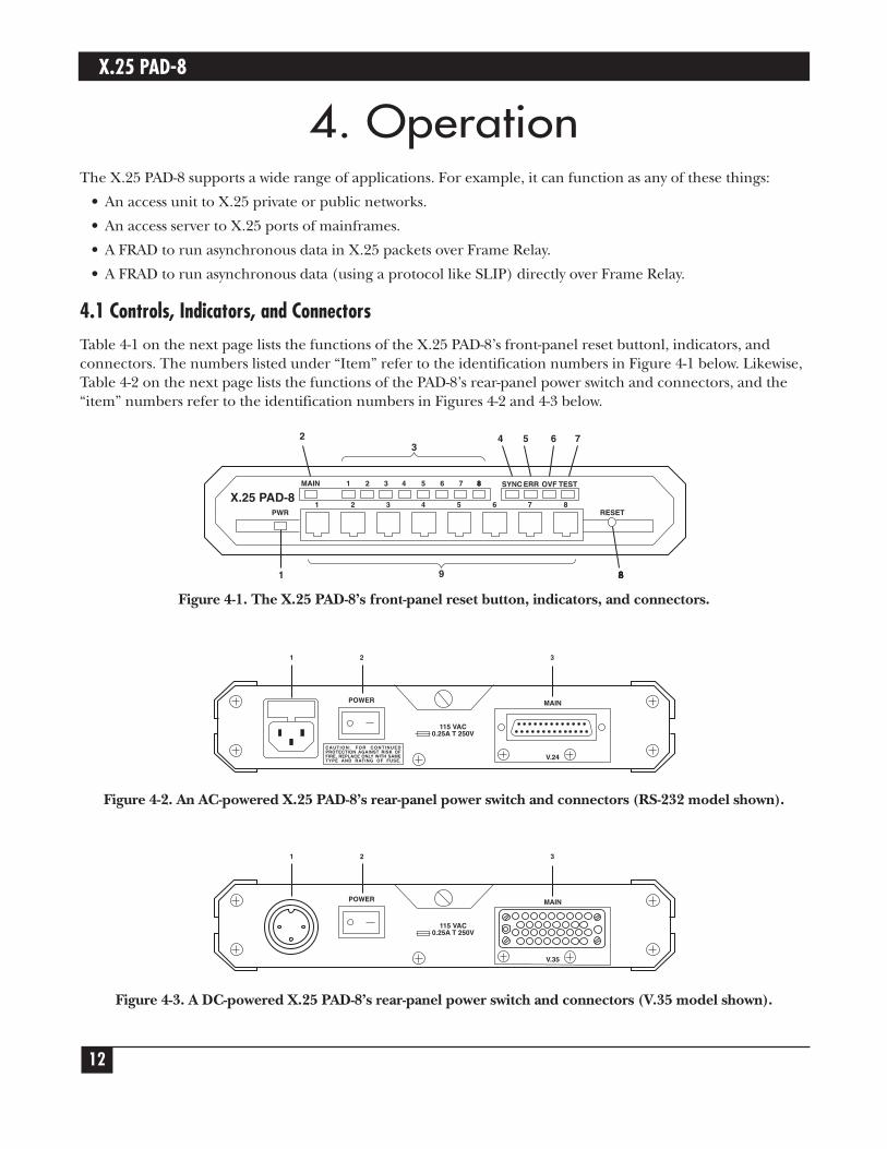
4.1 Controls, Indicators, and ConnectorsTable 4-1 on the next page lists the functions of the X.25 PAD-8’s front-panel reset buttonl, indicators, andconnectors. The numbers listed under “Item” refer to the identification numbers in Figure 4-1 below. Likewise,Table 4-2 on the next page lists the functions of the PAD-8’s rear-panel power switch and connectors, and the“item” numbers refer to the identification numbers in Figures 4-2 and 4-3 below.
Figure 4-1. The X.25 PAD-8’s front-panel reset button, indicators, and connectors.
Figure 4-2. An AC-powered X.25 PAD-8’s rear-panel power switch and connectors (RS-232 model shown).
Figure 4-3. A DC-powered X.25 PAD-8’s rear-panel power switch and connectors (V.35 model shown).
POWER MAIN
1
V.35
115 VAC0.25A T 250V
2 3
POWER MAIN
CAUTION: FOR CONTINUEDPROTECTION AGAINST RISK OFFIRE, REPLACE ONLY WITH SAMETYPE AND RATING OF FUSE.
1
V.24
115 VAC0.25A T 250V
2 3
SYNC ERR OVF TEST
87654321
MAIN 1 2 3 4 5 6 7 88
9
4 5 6 73
8
RESETPWR
X.25 PAD-8
881
2

CHAPTER 4: Operation
13
Table 4-1. Controls, Indicators, and Connectors
Item Control, Indicator, or Connector Function1 PWR Indicator On when the X.25 PAD-8 is powered.
2 Main Link Activity Indicators On when the link is active (receives or transmits frames).
3 Channel Activity Indicators On when the corresponding channel is active (receives or transmits data).(one for each channel)
4 SYNC Indicators Indicates X.25 PAD-8 synchronization status:Off when the X.25 PAD-8 not powered.On when the X.25 PAD-8 is powered and synchronized with the
corresponding peer.Blinks continuously when the X.25 PAD-8 is powered, but not
synchronized with its peer.
5 ERR Indicator On when a hardware malfunction was detected during the self-test.
6 OVF Indicator On when the X.25 PAD-8 buffers are full. This condition usually indicates that one of the DTE units connected to the X.25 PAD-8 does not respond to the X.25 PAD-8’s flow-control commands, a condition that may be caused by incorrect configuration of the X.25 PAD-8.
7 TEST Indicator On when the X.25 PAD-8 is in the diagnostics mode (a test loop is active). Traffic is not interrupted.
8 RESET Button Resets the X.25 PAD-8’s internal circuits (including the data buffers) and initiates the power-up self-test.
9 Channel Connectors Connection to X.25 PAD-8 channels (one connector per channel).
Table 4-2. X.25 PAD-8 Rear-Panel Controls and Indicators
Item Control or Connector Function1 Power Connector AC power connector with integral fuse.2 Power Switch Turns the X.25 PAD-8 on.3 Links Connectors Connection to link.

X.25 PAD-8
14
4.2 Operating ProcedureThe X.25 PAD-8 normally operates unattended. Operator intervention is only required when setting up theX.25 PAD-8 for the first time or when adapting it to new operational requirements.
NOTEThe X.25 PAD-8’s configuration is stored in nonvolatile memory and is not affected when power is turnedoff.
4.2.1 POWER-ON
1. Connect the power cable to the X.25 PAD-8’s rear power connector.
2. Set the power switch to ON. The PWR indicator should light.
If the link to its synchronous DTE/DCE peer is not operational yet, the SYNC indicator of the X.25 PAD-8blinks. Wait until the link becomes operational, and check that the SYNC indicator stops blinking andlights continuously.
3. Check that the ERR, OVF, and TEST indicators turn off after the X.25 PAD-8’s initial self-test.
4.2.2 NORMAL OPERATION
During normal operation, the PWR, SYNC, and MAIN indicators light continuously and the TEST, OVF, andERR indicators must remain off.
Channel-activity indicators blink according to the traffic load, and turn off if the channel is idle.
4.2.3 POWER-OFF
To turn the X.25 PAD-8 off, set the power switch to OFF.

CHAPTER 4: Operation
15
4.3 Upgrading the PAD-8‘s SoftwareBecause the X.25 PAD-8 has flash memory, you can upgrade its software without replacing its EPROMS. To doso, take these steps:
1. Connect a PC running terminal emulation to channel port 1 on the PAD-8. (Alternatively, if your PAD-8has an RS-232 main-link port, you can attach the PC to that port.) Configure the terminal emulator totransmit and receive at 9600 bps using no parity, 8 data bits, and 1 stop bit (“9600,N,8,1”).
2. Press a key on the terminal keyboard. You will be prompted to enter a password; just hit [Enter] (theSwitch’s default password state is no password at all). The Main menu will appear:
MAIN MENU
---------
1) CONFIGURE
2) SYSTEM CONTROL
3) DIAGNOSTICS
4) STATUS AND STATISTICS
5) LOGOUT
SELECT:
3. From the Main menu, select option 2. The System Control menu appears.
SYSTEM CONTROL MENU
-------------------
1) Link down
2) Link up
3) Clear Channel
4) Clear LCN
5) Update date
6) Update time
7) Reset statistics
8) Rearrange NOVRAM
9) Reset
10) Set default configuration
11) Disconnect dial link
12) Enable software upgrade
CR) EXIT
SELECT:
X.25 PAD-8
16
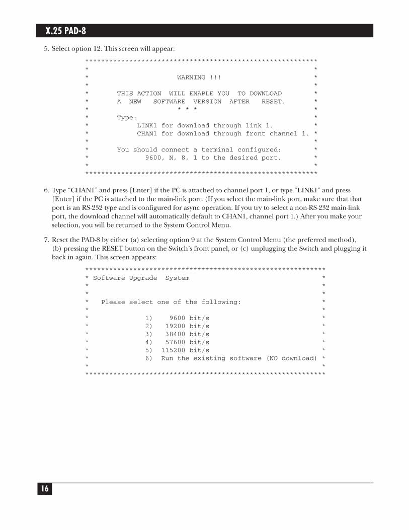
5. Select option 12. This screen will appear:
*********************************************************** ** WARNING !!! ** ** THIS ACTION WILL ENABLE YOU TO DOWNLOAD ** A NEW SOFTWARE VERSION AFTER RESET. ** * * * ** Type: ** LINK1 for download through link 1. ** CHAN1 for download through front channel 1. ** ** You should connect a terminal configured: ** 9600, N, 8, 1 to the desired port. ** ***********************************************************
6. Type “CHAN1” and press [Enter] if the PC is attached to channel port 1, or type “LINK1” and press[Enter] if the PC is attached to the main-link port. (If you select the main-link port, make sure that thatport is an RS-232 type and is configured for async operation. If you try to select a non-RS-232 main-linkport, the download channel will automatically default to CHAN1, channel port 1.) After you make yourselection, you will be returned to the System Control Menu.
7. Reset the PAD-8 by either (a) selecting option 9 at the System Control Menu (the preferred method),(b) pressing the RESET button on the Switch’s front panel, or (c) unplugging the Switch and plugging itback in again. This screen appears:
************************************************************* Software Upgrade System ** ** ** Please select one of the following: ** ** 1) 9600 bit/s ** 2) 19200 bit/s ** 3) 38400 bit/s ** 4) 57600 bit/s ** 5) 115200 bit/s ** 6) Run the existing software (NO download) ** *************************************************************
CHAPTER 4: Operation
17
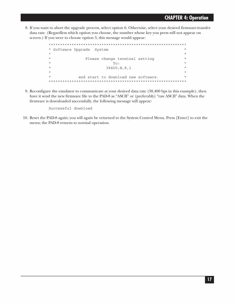
8. If you want to abort the upgrade process, select option 6. Otherwise, select your desired firmware-transferdata rate. (Regardless which option you choose, the number whose key you press will not appear onscreen.) If you were to choose option 3, this message would appear:
************************************************************* Software Upgrade System ** ** Please change terminal setting ** To: ** 38400,N,8,1 ** ** and start to download new software. *************************************************************
9. Reconfigure the emulator to communicate at your desired data rate (38,400 bps in this example), thenhave it send the new firmware file to the PAD-8 as “ASCII” or (preferably) “raw ASCII” data. When thefirmware is downloaded successfully, the following message will appear:
Successful download
10. Reset the PAD-8 again; you will again be returned to the System Control Menu. Press [Enter] to exit themenu; the PAD-8 returns to normal operation.

X.25 PAD-8
18
5. Troubleshooting5.1 Possible SolutionsIf a problem occurs, you can perform the following preliminary steps to return the X.25 PAD-8 to normaloperation.
To perform preliminary troubleshooting:
1. Check if the X.25 PAD-8 is turned on (PWR indicator is on).
2. Check if the cables are properly connected.
3. Check if the equipment connected to the X.25 PAD-8 is turned on and operates normally.
4. Check X.25 PAD-8’s LEDs.
5. Check if the configurations of the X.25 PAD-8 PAD and the remote PAD or switch correspond to therequirements of the attached equipment.
6. If steps 1 through 5 do not correct the problem, press RESET or turn the X.25 PAD-8 off and then onagain.
If the problem persists, see Chapter 5 in the Packet Switching Guide for other possible solutions.
5.2 Calling Black BoxIf you determine that your X.25 PAD-8 is malfunctioning, do not attempt to alter or repair the unit. It containsno user-serviceable parts. Contact Black Box at 724-746-5500.
Before you do, make a record of the history of the problem. We will be able to provide more efficient andaccurate assistance if you have a complete description, including:
• the nature and duration of the problem.
• when the problem occurs.
• the components involved in the problem.
• any particular application that, when used, appears to create the problem or make it worse.
• the results of any testing you’ve already done.
5.3 Shipping and PackagingIf you need to transport or ship your X.25 PAD-8:
• Package it carefully. We recommend that you use the original container.
• If you are shipping the X.25 PAD-8 for repair, make sure you include everything that came in the originalpackage. Before you ship, contact Black Box to get a Return Authorization (RA) number.

APPENDIX: The DC-Powered Version
19
Appendix: The DC-Powered Version
NOTEIgnore this appendix if your unit operates on AC power.
The DC-powered X.25 PAD-8 has a standard 3-pin male power-inlet connector on its rear panel (see Figure A-1below). The PAD-8 also comes with a matching female connector for attaching to your power-supply cord.
Figure A-1. The DC power inlet.
Make sure that the voltage polarity of the power-supply cord’s wires is correct:
• If your power-supply cord already has a compatible connector, just verify that the voltage polarity is asrequired.
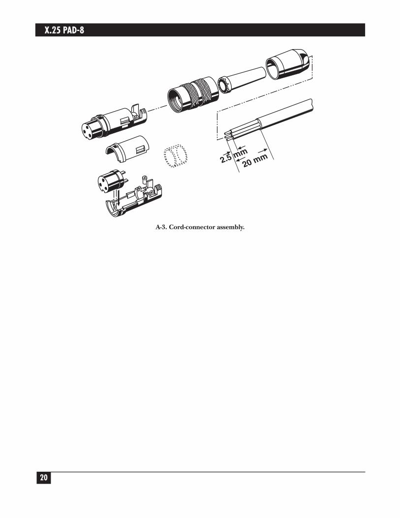
• If not, connect the wires of your power-supply cord to the supplied cable connector, according to thevoltage polarity shown in Figure A-2 below. Note that the solder side of the connector is shown. Refer toFigure A-3 on the next page for a detailed illustration of how to assemble this connector.
WARNING!Reversing the wires’ voltage polarity can cause serious damage to the unit.
Figure A-2. Voltage polarity (solder side) of the power cord’s female connector.
CHASSISGND
(Frame)
For -24 or -48 VDCGROUND
(0)1 3
2
VDC INPUT(Negative pole)
CHASSISGND
(Frame)
For +24 or +48 VDCVDC INPUT
(Positive pole)1 3
2
GROUND(0)
CHASSGND
48V+ -24V
X.25 PAD-8
20
A-3. Cord-connector assembly.
2.5 mm20 mm

1000 Park Drive • Lawrence, PA 15055-1018 • 724-746-5500 • Fax 724-746-0746
© Copyright 1999. Black Box Corporation. All rights reserved.


![CURVA EN R2 Y EN R3[1]](https://img.dokumen.tips/doc/110x75/55355f834a795941208b457e/curva-en-r2-y-en-r31.jpg)