Embed Size (px)
Citation preview
X-Port™ 20 Switch (XP20-2000i)
Installation Guide
for a
2000i with an
NEC MT860 or NEC MT1060
Projector
99-00486-00 Rev B0

FCC Warning This equipment has been tested and found to comply with the limits for a Class A digital device, pursuant to Part 15 of the FCC Rules. These limits are designed to provide reasonable protection against harmful interference when the equipment is operated in a commercial environment. This equipment generates, uses and can radiate radio frequency energy and, if not installed and used in accordance with the manufacturer’s instructions, may cause harmful interference to radio communications. Operation of this equipment in a residential area is likely to cause harmful interference, in which case the user will be required to correct the interference at his own expense. Trademark Notice SMART Board, X-Port and all SMART product logo types are trademarks of SMART Technologies Inc. All other third-party product and company names are mentioned for identification purposes only and may be trademarks of their respective owners.
Copyright Notice © 2004 SMART Technologies Inc. All rights reserved. No part of this publication may be reproduced, transmitted, transcribed, stored in a retrieval system or translated into any language in any form by any means without the prior written consent of SMART. Information in this manual is subject to change without notice and does not represent a commitment on the part of SMART.
U.S. Patent No. 5,448,263 and 6,141,000. Canadian Patent No. 2,058,219. Other U.S, Canadian and foreign patents pending.
99-00486-00 Rev B0

Contents
Installing the X-Port 20 Switch in a 2000i-DV/DVX..........................1 To install the X-Port 20 switch .................................................................. 1 To connect a Guest Laptop....................................................................... 7
Contacting SMART Technical Support ............................................8 General Inquiries ........................................................................................... 8 Warranty ........................................................................................................ 8
99-00486-00 Rev B0

99-00486-00 Rev B0

Installing the X-Port 20 in a 2000i with an NEC MT860 or MT1060 Projector These instructions show you how to:
• install an X-Port 20 switch in a 2000i that’s equipped with an NEC 860 or 1060 projector
• connect a guest laptop The X-Port 20 unit is an RS-232 serial switch for connecting a laptop to the interactive whiteboard. A user can then write over the displayed laptop image with a pen tray stylus and control the laptop by touching the interactive screen. With an X-Port 20 unit, the user can also switch between the laptop, the resident computer and a VCR/DVD player from the Control Panel on the 2000i.
Guest Laptop DB9 Serial IN
Serial OUT Ribbon Cable
Serial IN Gender Changer
IC Input Jack2
Components of the X-Port 20 Switch
You’ll need a Phillips® No. 1 screwdriver (not supplied) and a 5/32" hex key (not supplied with this kit, but available in the accessory kit for the 2000i) to perform this installation.
CAUTION: You should wear the supplied antistatic wrist strap throughout this installation. This wrist strap protects electronic components from damage due to electrostatic discharge. Attach the adhesive end of the strap to your wrist and wrap the copper tape on the other end around a grounded object.
To install the X-Port 20 switch 1. Shut down the computer. Then press and hold the Projector Standby button on the Control
Panel until it starts blinking rapidly. Wait until you hear the projector cooling fan stop (6–7 minutes), and then unplug the 2000i from the power outlet.
Projector Standby Button
2. Make sure the casters are locked and all four tip feet are extended.
X-Port 20 Switch Installation Guide for the 2000i 99-00486-00 Rev B0 1
3. Remove the sticker covering the lower DB9 opening. Place the supplied label over this opening.
DB9 Connector Opening(Sticker Removed)
Supplied Label2000i (Back Leg Removed for Clarity)
Computer 2
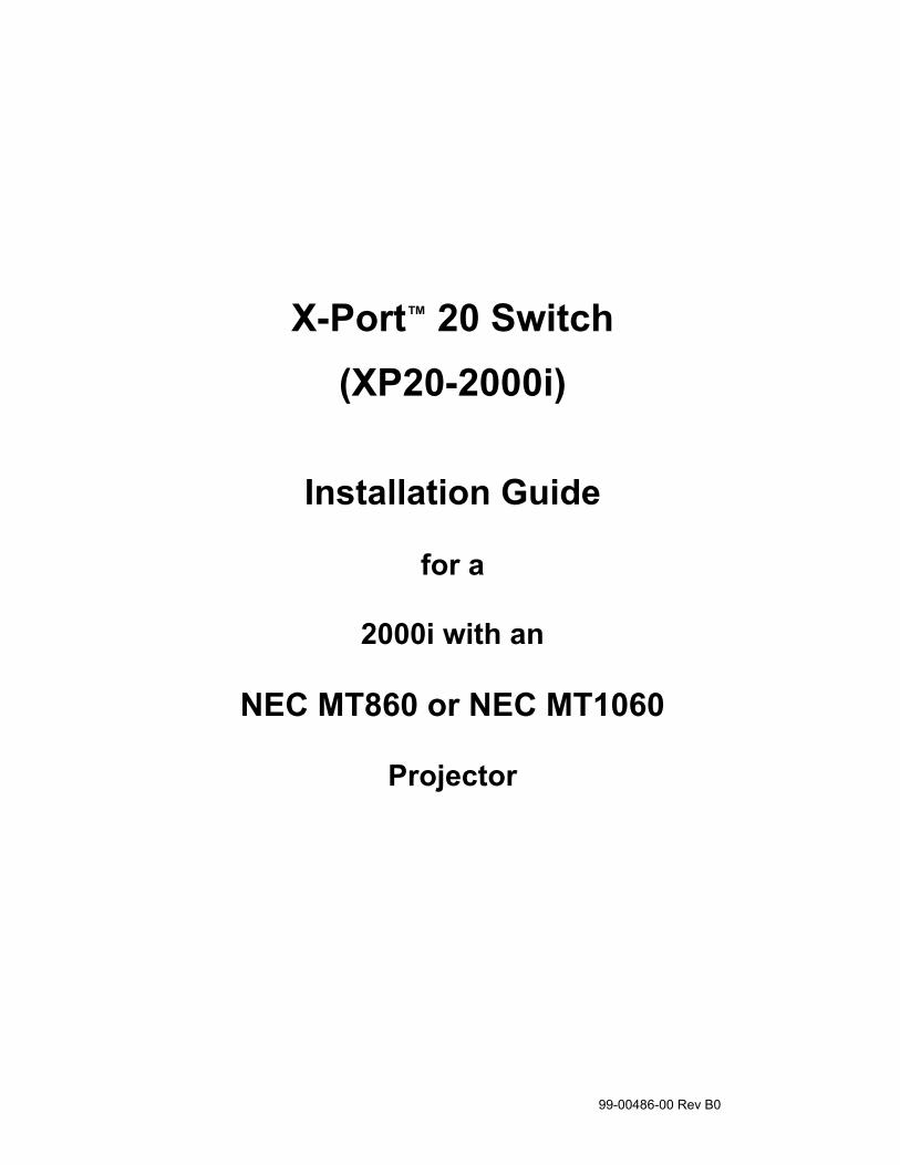
4. While propping up the Electronics tray with one hand (so it doesn’t fall suddenly), remove the
two button head screws on either side, using the 5/32" hex key (provided in the accessory kit for the 2000i). Put the screws in a safe place as you’ll need them to secure the Electronics tray at the end of this installation.
Button Head Screw Button Head Screw Location of Button Head Screws
X-Port 20 Switch Installation Guide for the 2000i 99-00486-00 Rev B0 2
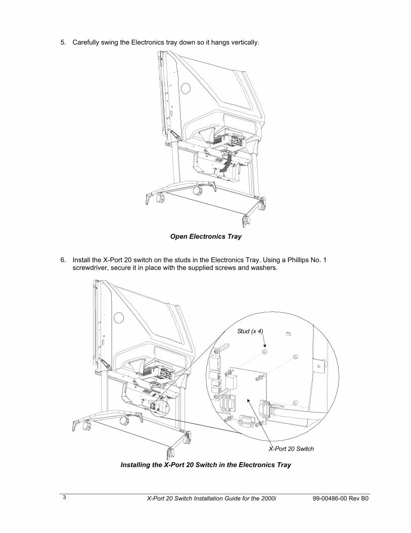
5. Carefully swing the Electronics tray down so it hangs vertically.
Open Electronics Tray
6. Install the X-Port 20 switch on the studs in the Electronics Tray. Using a Phillips No. 1 screwdriver, secure it in place with the supplied screws and washers.
X-Port 20 Switch
Stud (x 4)
Installing the X-Port 20 Switch in the Electronics Tray
X-Port 20 Switch Installation Guide for the 2000i 99-00486-00 Rev B0 3
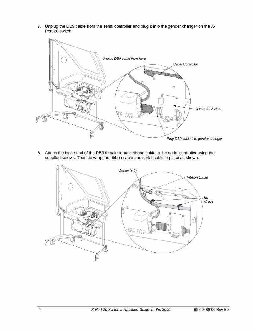
7. Unplug the DB9 cable from the serial controller and plug it into the gender changer on the X-Port 20 switch.
Unplug DB9 cable from here
Serial Controller
Plug DB9 cable into gender changer
X-Port 20 Switch
8. Attach the loose end of the DB9 female-female ribbon cable to the serial controller using the
supplied screws. Then tie wrap the ribbon cable and serial cable in place as shown.
Tie Wraps
Ribbon Cable
Screw (x 2)
X-Port 20 Switch Installation Guide for the 2000i 99-00486-00 Rev B0 4
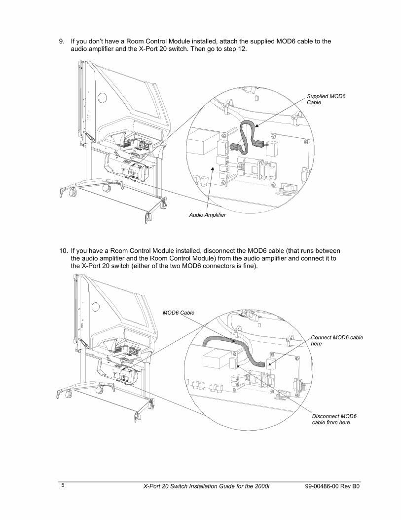
9. If you don’t have a Room Control Module installed, attach the supplied MOD6 cable to the audio amplifier and the X-Port 20 switch. Then go to step 12.
Supplied MOD6 Cable
Audio Amplifier
10. If you have a Room Control Module installed, disconnect the MOD6 cable (that runs between the audio amplifier and the Room Control Module) from the audio amplifier and connect it to the X-Port 20 switch (either of the two MOD6 connectors is fine).
MOD6 Cable
Disconnect MOD6 cable from here
Connect MOD6 cable here
X-Port 20 Switch Installation Guide for the 2000i 99-00486-00 Rev B0 5
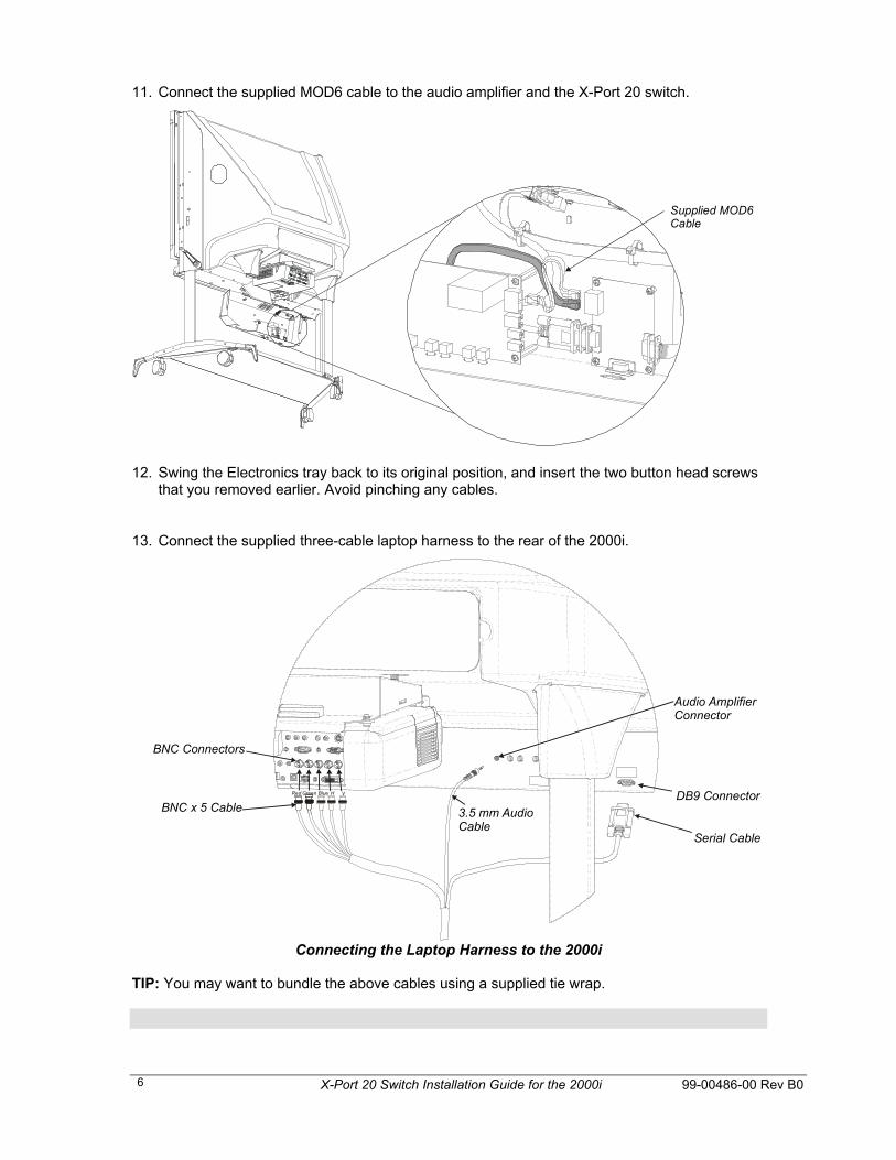
11. Connect the supplied MOD6 cable to the audio amplifier and the X-Port 20 switch.
Supplied MOD6 Cable
12. Swing the Electronics tray back to its original position, and insert the two button head screws
that you removed earlier. Avoid pinching any cables.
13. Connect the supplied three-cable laptop harness to the rear of the 2000i.
BNC x 5 Cable Red Green Blue H V
BNC Connectors
Serial Cable
DB9 Connector3.5 mm Audio Cable
Audio Amplifier Connector
Connecting the Laptop Harness to the 2000i
TIP: You may want to bundle the above cables using a supplied tie wrap.
X-Port 20 Switch Installation Guide for the 2000i 99-00486-00 Rev B0 6

To connect a Guest Laptop 1. Extend the laptop end of the umbilical from the rear of the 2000i until it reaches the
laptop/videoconferencing shelf.
2. Connect the three cables that comprise the laptop end of the umbilical − the Computer 2 Audio, Computer 2 Video and Computer 2 Serial − to the appropriate connectors on the guest laptop.
3. If the laptop is off, turn it on.
4. Press the Display Source button to switch to the guest-laptop video source.
The LED for the guest laptop (on the Control Panel) blinks slowly as the display source changes, and then remains illuminated once the guest laptop becomes the video source. If you continue to use the guest laptop video source for any period longer than a minute, you'll return to the host computer video source the next time you press the Display Source button. To use the VCR/DVD player video source, press the Display Source button twice, waiting only briefly between presses.
If the initialization screen does not appear on the interactive whiteboard
Try activating the external video port on your laptop computer. Some laptops can't display their internal screens and activate the external video port or external monitor at the same time. You may also need to deactivate the internal video port on your laptop or put the internal and external video ports into simultaneous display mode, so that the laptop displays on both the laptop monitor and the interactive whiteboard at the same time.
With newer laptops, you can synchronize the internal and external video ports at the software level, as follows:
1 From the Start menu, select Settings > Control Panel > Display.
2 Click the Refresh (or Monitor Refresh) tab.
3 Click the CRT/Panel option to activate simultaneous monitor and external video port display.
This may not be possible with older laptop models, in which case you’ll have to switch back and forth between the internal and external video port. If you aren't sure which commands or keyboard combinations are required to do this, check the user’s manual for your laptop.
You can now display the output of your laptop or external computer.
If the image on the screen is too large or too small The projector and external computer resolution may not match. To adjust your computer resolution
to match the projector resolution, click the Start button, and select Settings > Control Panel > Display. Click the Settings tab, and adjust the resolution accordingly.
5. Insert the SMART Board software CD into the laptop’s CD-ROM drive, and follow the on-screen instructions. After installing the software, you should orient the interactive screen to ensure that the cursor tracks your finger and the pen tray tools accurately. To do this, click the Orient button in the SMART Board tools and follow the on-screen instructions.
X-Port 20 Switch Installation Guide for the 2000i 99-00486-00 Rev B0 7
X-Port 20 Switch Installation Guide for the 2000i 99-00486-00 Rev B0 8
Customer Support SMART’s Technical Support team welcomes your call. However, you may want to contact your local reseller first if you experience problems with any SMART product. SMART’s resellers can readily provide you with quick advice so you can enjoy the benefits of the X-Port 20 switch for the Rear Projection SMART Board 2000i interactive whiteboard without delay.
Contacting SMART Technical Support All SMART software includes free telephone, fax and e-mail support. There are a number of ways to contact SMART Technical Support: Telephone: toll-free at 1.866.518.6791 or outside North America at +1.403.228.5940
(Available 7 a.m. − 6 p.m. Mountain Time from Monday to Friday) Fax: 403.245.0366 E-mail: [email protected] Web site: www.smarttech.com
Please note when you purchased the X-Port 20 switch, the reseller’s name and the serial number so we may better assist you.
General Inquiries Main switchboard: toll-free at 1.888.42.SMART or outside North America at +1.403.245.0333 Fax: 403.228.2500 E-mail: [email protected]
Our address: SMART Technologies Inc. Suite 300, 1207 − 11th Avenue SW Calgary, AB CANADA T3C 0M5
Warranty The X-Port 20 switch is covered by a one-year parts and labor warranty. Customers must return any defective merchandise to an authorized service center as directed by the distributor, dealer or manufacturer.
Shipping charges incurred from warranty service are paid as follows: The customer is responsible for shipping the system to the service center. SMART pays return shipping via ground service on any product returned for service within the warranty period. Any charges associated with a customer-requested rush order are billed to the customer. Following the warranty period, the customer is responsible for shipping the product to and from the service center. Read the warranty shipped with your X-Port 20 switch for details.