Embed Size (px)
Citation preview
b a 52306e 01 02 /2002
HOSKIN SCIENTIFIC LTD
AR
S T O
C A LR C L
M
O
6719 2
7 O
°C
m g /l
A R n gT P
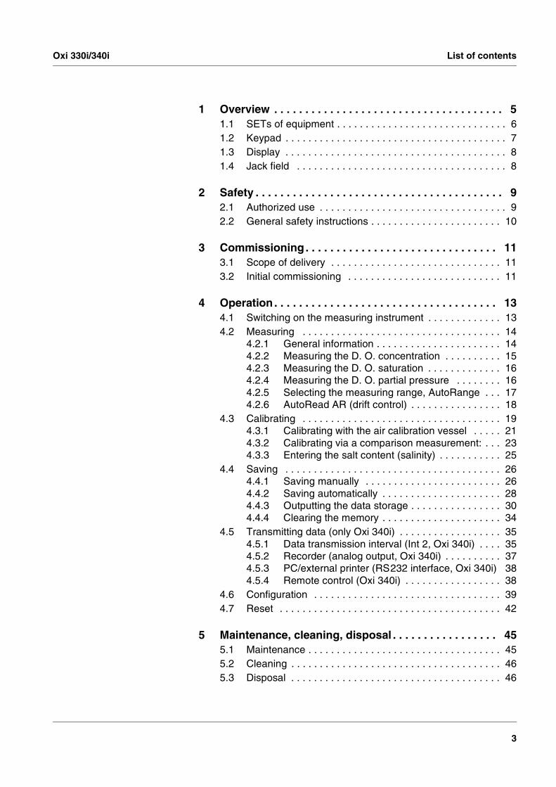
Oxygen measuring instrument
WTW Handheld meterOxi 330i/340i
239 East 6th Avenue,Vancouver, BC V5T 1J7Phone (604) 872-7894 Fax (604) 872-0281email [email protected] 4210 Morris Drive,Burlington, ON L7L 5L6Phone (905) 333-5510 Fax (905) 333-4976email [email protected] 8425 Devonshire,Montreal, PQ H4P 2L1Phone (514) 735-5267 Fax (514) 735-3454email [email protected]
Operating manual

Accuracy whengoing to press
The use of advanced technology and the high quality standard of our instruments are the result of continuous development. This may result in differences between this operating manual and your instrument. Al-so, we cannot guarantee that there are absolutely no errors in this man-ual. Therefore, we are sure you will understand that we cannot accept any legal claims resulting from the data, figures or descriptions.
Warranty We guarantee the instrument described for 3 years from the date of purchase. The instrument warranty covers manufacturing faults that are discov-ered within the warranty period. The warranty does not cover compo-nents that are replaced during maintenance work, e.g. batteries.
The warranty claim extends to restoring the instrument to readiness for use but not, however, to any further claim for damages. Improper han-dling or unauthorized opening of the instrument invalidates any warran-ty claim.
To ascertain the warranty liability, return the instrument and proof of purchase together with the date of purchase freight paid or prepaid.
Copyright © Weilheim 2002, WTW GmbH & Co. KGReproduction in whole - or even in part - is prohibited without the ex-press written permission of WTW GmbH, Weilheim & Co. KG.Printed in Germany.
Oxi 330i/340i List of contents
3
1 Overview . . . . . . . . . . . . . . . . . . . . . . . . . . . . . . . . . . . . . 51.1 SETs of equipment . . . . . . . . . . . . . . . . . . . . . . . . . . . . . . 61.2 Keypad . . . . . . . . . . . . . . . . . . . . . . . . . . . . . . . . . . . . . . . 71.3 Display . . . . . . . . . . . . . . . . . . . . . . . . . . . . . . . . . . . . . . . 81.4 Jack field . . . . . . . . . . . . . . . . . . . . . . . . . . . . . . . . . . . . . 8
2 Safety . . . . . . . . . . . . . . . . . . . . . . . . . . . . . . . . . . . . . . . . 92.1 Authorized use . . . . . . . . . . . . . . . . . . . . . . . . . . . . . . . . . 92.2 General safety instructions . . . . . . . . . . . . . . . . . . . . . . . 10
3 Commissioning . . . . . . . . . . . . . . . . . . . . . . . . . . . . . . . 113.1 Scope of delivery . . . . . . . . . . . . . . . . . . . . . . . . . . . . . . 113.2 Initial commissioning . . . . . . . . . . . . . . . . . . . . . . . . . . . 11
4 Operation . . . . . . . . . . . . . . . . . . . . . . . . . . . . . . . . . . . . 134.1 Switching on the measuring instrument . . . . . . . . . . . . . 134.2 Measuring . . . . . . . . . . . . . . . . . . . . . . . . . . . . . . . . . . . 14
4.2.1 General information . . . . . . . . . . . . . . . . . . . . . . 144.2.2 Measuring the D. O. concentration . . . . . . . . . . 154.2.3 Measuring the D. O. saturation . . . . . . . . . . . . . 164.2.4 Measuring the D. O. partial pressure . . . . . . . . 164.2.5 Selecting the measuring range, AutoRange . . . 174.2.6 AutoRead AR (drift control) . . . . . . . . . . . . . . . . 18
4.3 Calibrating . . . . . . . . . . . . . . . . . . . . . . . . . . . . . . . . . . . 194.3.1 Calibrating with the air calibration vessel . . . . . 214.3.2 Calibrating via a comparison measurement: . . . 234.3.3 Entering the salt content (salinity) . . . . . . . . . . . 25
4.4 Saving . . . . . . . . . . . . . . . . . . . . . . . . . . . . . . . . . . . . . . 264.4.1 Saving manually . . . . . . . . . . . . . . . . . . . . . . . . 264.4.2 Saving automatically . . . . . . . . . . . . . . . . . . . . . 284.4.3 Outputting the data storage . . . . . . . . . . . . . . . . 304.4.4 Clearing the memory . . . . . . . . . . . . . . . . . . . . . 34
4.5 Transmitting data (only Oxi 340i) . . . . . . . . . . . . . . . . . . 354.5.1 Data transmission interval (Int 2, Oxi 340i) . . . . 354.5.2 Recorder (analog output, Oxi 340i) . . . . . . . . . . 374.5.3 PC/external printer (RS232 interface, Oxi 340i) 384.5.4 Remote control (Oxi 340i) . . . . . . . . . . . . . . . . . 38
4.6 Configuration . . . . . . . . . . . . . . . . . . . . . . . . . . . . . . . . . 394.7 Reset . . . . . . . . . . . . . . . . . . . . . . . . . . . . . . . . . . . . . . . 42
5 Maintenance, cleaning, disposal . . . . . . . . . . . . . . . . . 455.1 Maintenance . . . . . . . . . . . . . . . . . . . . . . . . . . . . . . . . . . 455.2 Cleaning . . . . . . . . . . . . . . . . . . . . . . . . . . . . . . . . . . . . . 465.3 Disposal . . . . . . . . . . . . . . . . . . . . . . . . . . . . . . . . . . . . . 46

List of contents Oxi 330i/340i
4
6 What to do if... . . . . . . . . . . . . . . . . . . . . . . . . . . . . . . . . 47
7 Technical data . . . . . . . . . . . . . . . . . . . . . . . . . . . . . . . . 51
8 Lists . . . . . . . . . . . . . . . . . . . . . . . . . . . . . . . . . . . . . . . . 55

Oxi 330i/340i Overview
5
1 Overview
The compact precision handheld meter Oxi 330i/340i enables you to carry out oxygen (D. O.) measurements rapidly and reliably. The Oxi330i/340i handheld meter provides the maximum degree of op-erating comfort, reliability and measuring certainty for all applications.
The proven OxiCal® calibration procedure and the special AutoRead function support you in your work with the Oxi handheld meter.
NoteIf you need further information or application notes, you can obtain the following material from WTW:
� Application reports
� Primers
� Safety datasheets.
You will find information on available literature in the WTW catalog or via the Internet.
1 Keypad
2 Sample display
3 Jack field
AR
M
O
6719 2
7 O
°C
mg/l
ARngTP
RCL
STO
CAL
1
2
3

Overview Oxi 330i/340i
6
1.1 SETs of equipment
The measuring instrument is also available as part of individual SETs of equipment. You will find additional information on this and other ac-cessories in the WTW catalog or via the Internet.
Set (sample configuration):
1 Measuring instrument, Oxi 330i/340i
2 Stand
3 – 50 ml ELY/G electrolyte solution for D.O. probes
– 50 ml RL/G cleaning solution for D.O. probes
– 3 WP 90/3 exchange membrane heads
– SF300 abrasive film for D.O. probes
4 CellOx 325 D.O. probe with calibration vessel
5 Plug-in power supply, optional (340i only)

Oxi 330i/340i Overview
7
1.2 Keypad
Key functions
RUN/ENTER
ARRCLCAL
STOM
Select the measuring mode <M>:
– D. O. concentration
– D. O. saturation
– D. O. partial pressure
Save a measured value<STO>
Switch measuring instrument on/off <ON/OFF>
Calibration; Select the calibration procedure <CAL>
Display/transmit measured values <RCL>
Activate/deactivate the AutoRead function <AR>
Switch on the salt content correction, Increase values, scroll <� >
Switch off the salt content correction, Decrease values, scroll <�>
Confirm entries, start AutoRead <RUN/ENTER>
M
STO
CAL
RCL
AR
RUN/ENTER

Overview Oxi 330i/340i
8
1.3 Display
1.4 Jack field
WarningOnly connect probes to the measuring instrument that cannot return any voltages or currents that are not allowed (> SELV and > current cir-cuit with current limiting). Nearly all probes - especially WTW probes - fulfill these conditions.
1 D. O. probe
2 Plug-in power supply (optional) - Oxi 340i only
3 Serial Interface RS 232 / analog output (recorder) ,Oxi 340i only
AutoCal DINAutoCal TEC
mV/pH
1/cmK/%°F
TDS UpH Sal
S/m cmcmM
Lin
Tref25 Tref20
nLF RCLAuto Store
Time BaudDay.Month No.
IdentYear
S
88 .88 88
O
C
% mg/l
LoBat ARng AR
TP
1
Cal
°
mbarSal
Status display
Meas. value display
Function and temperature display
Sensor symbol
3
1 2

Oxi 330i/340i Safety
9
2 Safety
This operating manual contains basic instructions that you must follow during the commissioning, operation and maintenance of the measur-ing instrument. Consequently, all responsible personnel must read this operating manual before working with the measuring system. The op-erating manual must always be available within the vicinity of the mea-suring system.
Target group The measuring instrument was developed for work in the field and in the laboratory. We assume that, as a result of their professional training and experi-ence, the operators will know the necessary safety precautions to take when handling chemicals.
Safetyinstructions
The individual chapters of this operating manual use safety instructions such as the label shown below to indicate various hazards or dangers:
Warningindicates instructions that must be followed precisely in order to avoid the possibility of slight injuries or damage to the instrument or the envi-ronment.
Further notes
Noteindicates notes that draw your attention to special features.
Noteindicates cross-references to other documents, e.g. operating manu-als.
2.1 Authorized use
The authorized use of the measuring instrument consists exclusively of the measurement of the dissolved oxygen (D. O.) content of liquid me-dia in the field and laboratory. The technical specifications as given in chapter 7 TECHNICAL DATA must be observed. Only the operation and running of the measuring instru-ment according to the instructions given in this operating manual is au-thorized. Any other use is considered to be unauthorized.
Safety Oxi 330i/340i
10
2.2 General safety instructions
This instrument is built and inspected according to the relevant guide-lines and norms for electronic measuring instruments (see chapter 7 TECHNICAL DATA). It left the factory in a safe and secure technical condition.
Function and operatingsafety
The smooth functioning and operational safety of the measuring instru-ment can only be guaranteed if the generally applicable safety mea-sures and the specific safety instructions in this operating manual are followed during operation.
The smooth functioning and operational safety of the measuring instru-ment can only be guaranteed under the environmental conditions that are specified in chapter 7 TECHNICAL DATA.
If the instrument was transported from a cold environment to a warm environment, the formation of condensate can lead to the faulty func-tioning of the instrument. In this event, wait until the temperature of the instrument reaches room temperature before putting the instrument back into operation.
Safe operation If safe operation is no longer possible, the instrument must be taken out of service and secured against inadvertent operation!Safe operation is no longer possible if the measuring instrument:
� has been damaged in transport
� has been stored under adverse conditions for a lengthy period of time
� is visibly damaged
� no longer operates as described in this manual.
If you are in any doubt, please contact the supplier of the instrument.
Obligations of thepurchaser
The purchaser of the measuring instrument must ensure that the fol-lowing laws and guidelines are observed when using dangerous sub-stances:
� EEC directives for protective labor legislation
� National protective labor legislation
� Safety regulations
� Safety datasheets of the chemical manufacturers.
Oxi 330i/340i Commissioning
11
3 Commissioning
3.1 Scope of delivery
� Handheld meter, Oxi 330i or 340i
� Plug-in power supply, optional (340i only)
� Operating manual and short operating manual
� 4 batteries, 1.5 V Mignon type AA (in the instrument)
3.2 Initial commissioning
Perform the following activities:
� Set the date and time
� Connect the plug-in power supply, optional (340i only)
Setting the date andtime 1 Press the <M> key and hold it down.
2 Press the <ON/OFF> key.The display test appears briefly on the display.
3 Press the <RUN/ENTER> key repeatedly until the date ap-pears on the display.
4 Set the date of the current day with <�> <�>.
5 Confirm with <RUN/ENTER>.The date (month) flashes in the display.
6 Set the current month with <�> <�>.
7 Confirm with <RUN/ENTER>. The year appears on the display.
8 Set the current year with <�> <�>.
9 Confirm with <RUN/ENTER>. The hours flash on the display.
10 Set the current time with <�> <�>.
11 Confirm with <RUN/ENTER>. The minutes flash on the display.
12 Set the current time with <�> <�>.
13 Confirm with <RUN/ENTER>.The instrument switches to the measuring mode, the sensor symbol flashes.
14 Switch the instrument off using <ON/OFF>.
Commissioning Oxi 330i/340i
12
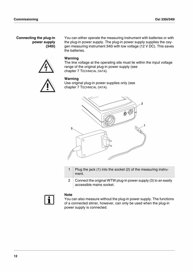
Connecting the plug-inpower supply
(340i)
You can either operate the measuring instrument with batteries or with the plug-in power supply. The plug-in power supply supplies the oxy-gen measuring instrument 340i with low voltage (12 V DC). This saves the batteries.
WarningThe line voltage at the operating site must lie within the input voltage range of the original plug-in power supply (see chapter 7 TECHNICAL DATA).
WarningUse original plug-in power supplies only (see chapter 7 TECHNICAL DATA).
NoteYou can also measure without the plug-in power supply. The functions of a connected stirrer, however, can only be used when the plug-in power supply is connected.
1 Plug the jack (1) into the socket (2) of the measuring instru-ment.
2 Connect the original WTW plug-in power supply (3) to an easily accessible mains socket.
2
13
Oxi 330i/340i Operation
13
4 Operation
4.1 Switching on the measuring instrument
Note The measuring instrument has an energy saving feature to avoid un-necessary battery depletion. The energy saving feature switches the measuring instrument off if no key has been pressed for an hour. The energy saving feature is not active when the AutoStore function is ac-tive.
Measuring instrument340i
The energy saving feature is also not active
� if the power is supplied by the plug-in power supply,
� if the communication cable and a PC with a running communication program are connected,
� if the recorder cable is connected,
� if the printer cable is connected (for external printers).
1 Connect the D. O. probe to the measuring instrument.
2 Press the <ON/OFF> key.The display test appears briefly on the display.The relative slope for the probe type that was just connected subsequently appears for approx. one second.The measuring instrument then automatically switches to the measuring mode that was last selected. The display shows the relevant measured value.

Operation Oxi 330i/340i
14
4.2 Measuring
4.2.1 General information
You can measure the following variables:
� D. O. concentration
� D. O. saturation
� D. O. partial pressure
The measuring instrument is supplied with the following functions:
� AutoRange (automatic measurement range selection),
� The AutoRead function (drift control) for checking the stability of the measurement signal. This ensures the reproducibility of the measur-ing signal. For details of how to switch the AutoRead function on/off, see section 4.2.6.
Preparatory activities Perform the following preparatory activities when you want to measure:
NoteIncorrect calibration of D. O. probes will result in incorrect measured values. Calibrate at regular intervals.
NoteThe Oxi 340i handheld oxygen meter automatically recognizes the type of D.O. sensor that is connected (CellOx 325 or DurOx 325).
Temperature sensor The D. O. probe has an integrated temperature sensor that always measures the current temperature of the test sample.
WarningWhen connecting an earthed PC/printer, measurements cannot be per-formed in earthed media as incorrect values would result. The RS232 interface is not galvanically isolated.
1 Connect the D. O. probe to the measuring instrument.
2 In conjunction with the D. O. probe, check or calibrate the mea-suring instument. How to calibrate is described in section 4.3.
3 Select the measuring mode with <M>.

Oxi 330i/340i Operation
15
4.2.2 Measuring the D. O. concentration
NoteWhen measuring the concentration of test samples with a salt content of more than 1 g/l, a salinity correction is required. For this, you have to measure and input the salinity of the measured medium first. This is de-scribed in section 4.3.3 ENTERING THE SALT CONTENT (SALINITY). Before measuring the oxygen, you have to switch on the salt content correction (see below).
You can measure the oxygen content without a salt content correction as follows:
Switching on/off the saltcontent correction
Proceed as follows to switch on the salt content correction:
1 Perform the preparatory activities according to section 4.2.1.
2 Immerse the D. O. probe in the test sample.
3 Press the <M> key repeatedly until the D. O. concentration in mg/l appears on the display.
ARng
%
LoBat Cal AR
8 °FSal
mbar
S
1
RCLAuto Store
1/cm/K%
TDS UpH SalmV/pH
S/m cmcmM
Lin
Tref25 Tref20
nLF
AutoCal DINAutoCal TEC
Time BaudDay.Month No.
IdentYear 6719 27
O
°C
mg/l
TP
1 In the D. O. concentration measuring mode, switch on the salt content correction with <� >. The SAL display indicator ap-pears on the display. The value that was entered is taken into consideration during the measurement (see section 4.3.3).
cmcmM
%
LoBat Cal AR
8 °F
mbar
S
1
RCLAuto Store
1/cm/K%
TDS UpH SalmV/pH
S/m
Lin
Tref25 Tref20
nLF
AutoCal DINAutoCal TEC
Time BaudDay.Month No.
IdentYear 6714 25
O
°C
mg/l
ARng
TP
Sal

Operation Oxi 330i/340i
16
4.2.3 Measuring the D. O. saturation
You can measure the D. O. saturation as follows:
4.2.4 Measuring the D. O. partial pressure
You can measure the D. O. partial pressure as follows:
2 Switch the salt content correction off with <�>. The SAL dis-play indicator is no longer displayed.
1 Perform the preparatory activities according to section 4.2.1.
2 Immerse the D. O. probe in the test sample.
3 Press the <M> key repeatedly until the saturation in % appears on the display.
1 Perform the preparatory activities according to section 4.2.1.
2 Immerse the D. O. probe in the test sample.
3 Press the <M> key repeatedly until the partial pressure in mbar appears on the display.
mg/l
LoBat Cal AR
8 °FSal
mbar
S
1
RCLAuto Store
1/cm/K%
TDS UpH SalmV/pH
S/m cmcmM
Lin
Tref25 Tref20
nLF
AutoCal DINAutoCal TEC
Time BaudDay.Month No.
IdentYear 6719 28
O
°CARng
TP
%
Oxi 330i/340i Operation
17
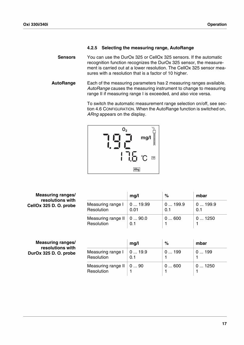
4.2.5 Selecting the measuring range, AutoRange
Sensors You can use the DurOx 325 or CellOx 325 sensors. If the automatic recognition function recognizes the DurOx 325 sensor, the measure-ment is carried out at a lower resolution. The CellOx 325 sensor mea-sures with a resolution that is a factor of 10 higher.
AutoRange Each of the measuring parameters has 2 measuring ranges available. AutoRange causes the measuring instrument to change to measuring range II if measuring range I is exceeded, and also vice versa.
To switch the automatic measurement range selection on/off, see sec-tion 4.6 CONFIGURATION. When the AutoRange function is switched on, ARng appears on the display.
Measuring ranges/resolutions with
CellOx 325 D. O. probe
Measuring ranges/resolutions with
DurOx 325 D. O. probe
%
LoBat Cal AR
8 °FSal
mbar
S
1
RCLAuto Store
1/cm/K%
TDS UpH SalmV/pH
S/m cmcmM
Lin
Tref25 Tref20
nLF
AutoCal DINAutoCal TEC
Time BaudDay.Month No.
IdentYear 6719 27
O
°C
mg/l
ARng
TP
mg/l % mbar
Measuring range I Resolution
0 ... 19.990.01
0 ... 199.90.1
0 ... 199.90.1
Measuring range IIResolution
0 ... 90.0 0.1
0 ... 6001
0 ... 12501
mg/l % mbar
Measuring range I Resolution
0 ... 19.90.1
0 ... 1991
0 ... 1991
Measuring range IIResolution
0 ... 901
0 ... 6001
0 ... 12501

Operation Oxi 330i/340i
18
4.2.6 AutoRead AR (drift control)
The AutoRead function (drift control) checks the stability of the mea-surement signal. The stability has a considerable effect on the repro-ducibility of the measured value.
Criteria With identical measurement conditions, the following applies:
1 Select the measuring mode with <M>.
2 Activate the AutoRead function with <AR>. The current mea-sured value is frozen (hold function).
3 Start AutoRead with <RUN/ENTER>.The AR display indicator flashes until a stable measured value is reached.
4 If necessary, start the next AutoRead measurement with <RUN/ENTER>.
5 To terminate the AutoRead function: Press the <AR> key.
7
RCL
%
LoBat Cal
8 °FSal
mbar
S
1Auto Store
1/cm/K%
TDS UpH SalmV/pH
S/m cmcmM
Lin
Tref25 Tref20
nLF
AutoCal DINAutoCal TEC
Time BaudDay.Month No.
IdentYear 6717 0
O
°C
mg/l
TP
ARng AR
Parameter Reproducibility Response time
D. O. concentration better than 0.05 mg/l > 10 seconds
D. O. saturation index better than 0.6 % > 10 seconds
D. O. partial pressure better than 0.6 mbar > 10 seconds

Oxi 330i/340i Operation
19
4.3 Calibrating
Why calibrate? D. O. probes age. This changes the slope of the D. O. probe. Calibra-tion determines the current slope of the probe and stores this value in the instrument. Thus, you should calibrate at regular intervals.
Separate calibration ofCellOx 325 and
DurOx 325
The Oxi 330i/340i handheld meter enables the two sensor types, CellOx 325 and DurOx 325, to be calibrated separately from one an-other. The calibration of a specific sensor type does not affect the cali-bration of the other sensor type. When connecting a sensor, the calibration data stored for the respective sensor type are automatically used.
Calibration procedures The Oxi 330i/340i provides 2 calibration procedures:
� Calibration in water vapor-saturated air. To calibrate the CellOx 325, use the OxiCal®-SL air calibration ves-sel (accessory), to calibrate the DurOx 325, use the OxiCal®-D air calibration vessel (contained in the scope of delivery of the sensor).
� Calibration via a comparison measurement (e. g. Winkler titration according to DIN EN 25813 or ISO 5813). At the same time, the rel-ative slope is adapted to the comparison measurement by a correc-tion factor.
When to calibrate? � After connecting another D. O. probe
� If the sensor symbol flashes, i. e. after the calibration interval has ex-pired
Setting thecalibration interval
The calibration interval (Int 3) is set to 14 days in the factory. You can select the interval in the range of 1 ... 999 days.
8LoBat
Time BaudDay.Month No.
IdentYear
Sal
%
mbar1S
RCLARStoreAuto
Cal
°F1/cm
/K%
TDS UpH SalmV/pH
S/m cmcmM
Lin
Tref25 Tref20
nLF
AutoCal DINAutoCal TEC
6719 27
O
°C
mg/l
ARng
TP
Operation Oxi 330i/340i
20
Printing the calibrationrecord (340i)
The calibration protocol contains the calibration data of the current cal-ibration. You can transmit the calibration protocol to a printer via the se-rial interface (see page 33).
NoteYou can automatically print a calibration protocol after the calibration. To do so, connect a printer to the interface according to section 4.5.3 before calibrating. After a valid calibration, the record is printed.
Sample printout:
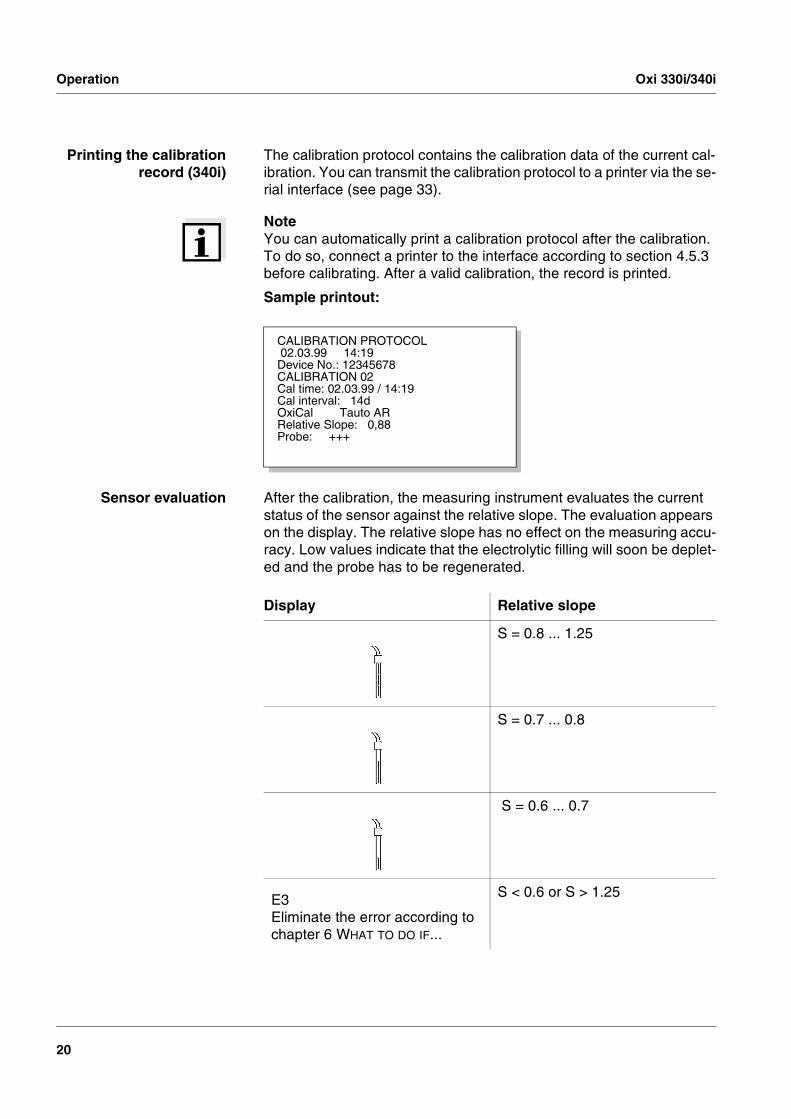
Sensor evaluation After the calibration, the measuring instrument evaluates the current status of the sensor against the relative slope. The evaluation appears on the display. The relative slope has no effect on the measuring accu-racy. Low values indicate that the electrolytic filling will soon be deplet-ed and the probe has to be regenerated.
CALIBRATION PROTOCOL 02.03.99 14:19Device No.: 12345678CALIBRATION 02Cal time: 02.03.99 / 14:19Cal interval: 14dOxiCal Tauto ARRelative Slope: 0,88Probe: +++
Display Relative slope
S = 0.8 ... 1.25
S = 0.7 ... 0.8
S = 0.6 ... 0.7
E3Eliminate the error according to chapter 6 WHAT TO DO IF...
S < 0.6 or S > 1.25
Oxi 330i/340i Operation
21
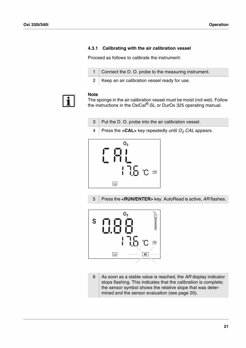
4.3.1 Calibrating with the air calibration vessel
Proceed as follows to calibrate the instrument:
NoteThe sponge in the air calibration vessel must be moist (not wet). Follow the instructions in the OxiCal®-SL or DurOx 325 operating manual.
1 Connect the D. O. probe to the measuring instrument.
2 Keep an air calibration vessel ready for use.
3 Put the D. O. probe into the air calibration vessel.
4 Press the <CAL> key repeatedly until O2 CAL appears.
5 Press the <RUN/ENTER> key. AutoRead is active, AR flashes.
6 As soon as a stable value is reached, the AR display indicator stops flashing. This indicates that the calibration is complete; the sensor symbol shows the relative slope that was deter-mined and the sensor evaluation (see page 20).
ARng
mg/l
8LoBat
Time BaudDay.Month No.
IdentYear
Sal
%
mbar1S
RCLARStoreAuto
°F1/cm
/K%
TDS UpH SalmV/pH
S/m cmcmM
Lin
Tref25 Tref20
nLF
AutoCal DINAutoCal TEC
671A LC
O
°C TP
Cal
ARng
mg/l
8LoBat
Time BaudDay.Month No.
IdentYear
Sal
%
mbar1
RCLStoreAuto
°F1/cm
/K%
TDS UpH SalmV/pH
S/m cmcmM
Lin
Tref25 Tref20
nLF
AutoCal DINAutoCal TEC
6718 80
O
°C TP
Cal AR
S

Operation Oxi 330i/340i
22
NoteIn chapter 6 WHAT TO DO IF... , you will find the measures to take for er-ror elimination.
7 Switch to the measuring mode with <M>.
ARng
mg/l
8LoBat
Time BaudDay.Month No.
IdentYear
Sal
%
mbar1
RCLStoreAuto
°F1/cm
/K%
TDS UpH SalmV/pH
S/m cmcmM
Lin
Tref25 Tref20
nLF
AutoCal DINAutoCal TEC
6718 80
O
°C TP
Cal AR
S

Oxi 330i/340i Operation
23
4.3.2 Calibrating via a comparison measurement
Proceed as follows to calibrate the instrument:
1 Connect the D. O. probe to the measuring instrument.
2 Press the <CAL> key repeatedly until O2 FAC appears.
3 Immerse the D. O. probe in the calibrating solution.
4 Press the <RUN/ENTER> key. The AutoRead measurement begins. If the measured value is stable, the instrument displays the determined measured value and the correction factor of the relative slope (initial value = 1.000).
5 Remove the D. O. probe from the calibrating solution.
6 Perform a comparison measurement (determine the nominal value). Leave the measuring instrument switched on until the nominal value is determined.
7 Set the displayed value on the measuring instrument to the nominal value with <�> <�>. This changes the related correc-tion factor of the relative slope.

Operation Oxi 330i/340i
24
NoteIf the correction factor deviates from 1.000, the display of the measured value units flashes.
8 Switch to the measuring mode with <M> or <RUN/ENTER> .

Oxi 330i/340i Operation
25
4.3.3 Entering the salt content (salinity)
A salt content correction is required in the oxygen concentration mea-surement of test samples with a salt content of more than 1 g/l. For this, you have to enter the salinity equivalent (the measured salinity) of the test sample (range 0.0 - 70.0) and to switch on the salinity correction.
Entering thesalt content
NoteHow to switch on the salt content correction is described on page 15.
Parameter Value range
Salinity 0.0 ... 70.0 in steps of 0.1
1 Determining the salinity of the test sample (any method).
2 Press the <CAL> key repeatedly until Sal appears on the dis-play.
3 Enter the salt content with <�> <�>.
4 Switch to the measuring mode with <M>.

Operation Oxi 330i/340i
26
4.4 Saving
The measuring instrument has an internal data memory. It can store up to 500 data records. A complete data record consists of:
� Storage location
� Date/time
� Measured value
� Temperature
� Temperature measuring procedure
� ID number
You can transmit measured values (data records) to the data storage in two ways:
� Save manually
� Switch on AutoStore (Int 1).
4.4.1 Saving manually
You can transmit a measured value to the data storage as follows:
1 Press the <STO> key.The current number (location number No.) of the next free stor-age location appears under the current measured value on the display.
2 Confirm with <RUN/ENTER>.The display switches to entering the ID number.
TP°C71
m
Sal
mg/l
8LoBat
Time BaudDay.Month
IdentYear
Salmbar1
S
RCLARAuto
Cal
°F1/cm
/K%
TDS UpHmV/pH
S/cmcmM
Lin
Tref25 Tref20
nLF
AutoCal DINAutoCal TEC
43 78
O
ARng
%
No.
Store

Oxi 330i/340i Operation
27
Message StoFullStoFullStoFullStoFull This message appears when all of the 500 storage locations are occu-pied.
You have the following options:
3 Using <�> <�>, enter the required ID number (1 ... 999).
4 Confirm with <RUN/ENTER>.The instrument changes to the measuring mode.
No.TP°C
m
Sal
mg/l
8LoBat
Time BaudDay.Month
Year
Salmbar1
S
RCLARAuto
Cal
°F1/cm
/K%
TDS UpHmV/pH
S/cmcmM
Lin
Tref25 Tref20
nLF
AutoCal DINAutoCal TEC
43 78
O
ARng
%
Store71Ident
Saving the current measured value. The oldest measured value (storage location 1) will be overwritten by this
Press <RUN/ENTER>.
Returning to the measuring mode without saving
press any key
Outputting the data storage see section 4.4.3
Clearing the memory see section 4.4.4

Operation Oxi 330i/340i
28
4.4.2 Saving automatically
The save interval (Int 1) determines the chronological interval between automatic save processes. After the fixed interval has expired, the current data record is transmit-ted to the storage and to the interface.
Setting the saveinterval:
The default setting for the save interval (Int 1) is OFF. By this, the AutoStore function is switched off. To switch the function on, set an interval (5 s, 10 s, 30 s, 1 min, 5 min, 10 min, 15 min, 30 min, 60 min):
1 Press the <RUN/ENTER> key and hold it down.
2 Press the <STO> key. Int 1 appears on the display.
3 Set the required interval between the saving procedures with <�> <�>.
4 Confirm with <RUN/ENTER>.The number of free memory locations appears on the display.
LoBatTref25nLF
/K%
RCL
Sal°
AR
TPC
Mm% mg/l
cmS/cm
S
8cm1/
°F
ARngCalLin
Tref20
SalTDS
mbar
OUpHmV/pH
AutoCal DINAutoCal TEC
Time BaudDay.Month No.
IdentYear FFOt 1n1
StoreAuto

Oxi 330i/340i Operation
29
NoteThe AutoStore function is interrupted if you start other functions, e.g. output the data storage. After the function is finished, the AutoStore function is continued. By this, however, temporal gaps in the recording of the measured values will occur.
Switching off AutoStore Switch AutoStore off by:
� setting the save interval (Int 1) to OFF, or
� switching the measuring instrument off and then on again.
5 As soon as all of the 500 storage locations are occupied, AutoStore is terminated (Int 1 = OFF). If there are not enough storage locations available for your measurements:
– Output and backup the data storage (see page 30) and
– clear the memory (see page 34).
6 Confirm with <RUN/ENTER>.The prompt for the ID number appears on the display.
7 Set the required ID number with <�> <�>.
8 Confirm with <RUN/ENTER>.The instrument switches to the Oxi measuring mode and starts the measuring and saving process.AutoStore flashes on the display.
erF9 99
S
1
LoBatTref25nLF
/K%
RCL
Sal°
AR
TPC
Mm% mg/l
cmS/cm
cm1/°F
ARngCalLin
Tref20
SalTDS
mbar
OUpHmV/pH
AutoCal DINAutoCal TEC
Time BaudDay.Month No.
Year 1StoreAuto
Ident

Operation Oxi 330i/340i
30
4.4.3 Outputting the data storage
You can output the contents of the data storage:
� Stored data on the display
� Calibration data on the display
� Stored data on the serial interface (only Oxi 340i)
� Calibration protocol to the interface (only Oxi 340i)
Outputting stored dataon the display
You can perform the following activities:
1 Press the <RCL> key repeatedly until StO dISP appears on the display.
2 Press the <RUN/ENTER> key. A measured value appears on the display. The storage location of the data record is displayed for approx. 2 s, then the respective temperature appears.
Display further elements of the data record (ID number, date, time, storage location)
Press <RUN/ENTER>.
Advance one data record (storage location) Press <�>
Go back one data record (storage location) Press <�>
StoreAuto
Ident
S
1
LoBatTref25nLF
/K%Sal
°
AR
TPC
Mm% mg/l
cmS/cm
cm1/°F
ARngCalLin
Tref20
SalTDS
mbar
OUpHmV/pH
AutoCal DINAutoCal TEC
Time BaudDay.Month No.
Year pS T OdIs
RCL
No.
StoreAuto
% /KSal1/cm
°F8
%mV/pH
mS/cmcmM
Sal
LoBat
Time BaudDay.Month
IdentYear
mbar1S
ARCal
TDS UpH
Lin
Tref25 Tref20
nLF
AutoCal DINAutoCal TEC
0 36O
ARng
mg/l
RCL
TP°C52 0

Oxi 330i/340i Operation
31
NoteIf you want to search for a certain element (e.g. date), proceed as fol-lows:
Outputting stored datato the interface (only Oxi
340i)
NoteYou can cancel the transmission with <M> or <RUN/ENTER>.
After the instrument number, the printout contains the complete storage contents in ascending order of the storage location numbers.
1 Using <RUN/ENTER>, select the element (e.g. date).
2 Press <�> or <�> repeatedly until the required date appears on the display.After approx. 2 s the temperature of the displayed measured value appears.
1 Press the <RCL> key repeatedly until Sto SEr appears on the display.
2 Press the <RUN/ENTER> key. The complete storage content is transmitted to the interface; during the data transmission the numbers of the currently transmitted storage locations run through. After the data trans-mission, the measuring instrument automatically switches to the measuring mode.
StoreAuto
Ident
S
1
LoBatTref25nLF
/K%Sal
°
AR
TPC
Mm% mg/l
cmS/cm
cm1/°F
ARngCalLin
Tref20
SalTDS
mbar
OUpHmV/pH
AutoCal DINAutoCal TEC
Time BaudDay.Month No.
Year RS t o
S ERCL
Operation Oxi 330i/340i
32
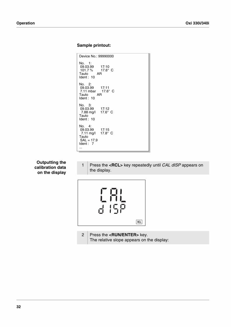
Sample printout:
Outputting thecalibration data
on the display
Device No.: 99990000
No. 1: 09.03.99 17:10 101.7 % 17.6° CTauto ARIdent : 10
No. 2: 09.03.99 17:11 7.11 mbar 17.6° CTauto ARIdent : 10
No. 3: 09.03.99 17:12 7.88 mg/l 17.6° CTautoIdent : 10
No. 4: 09.03.99 17:15 7.11 mg/l 17.8° CTauto SAL = 17.9Ident : 7...
1 Press the <RCL> key repeatedly until CAL dISP appears on the display.
2 Press the <RUN/ENTER> key. The relative slope appears on the display:
ARngConCal
StoreAuto
0No.
LoBat
Day.Month
Year Ident
UpH
AR
%°F°C TP
mV/pHmol/L
TempErrorAutoCal DIN CalError
AutoCal TEC
Time Baud1S
mg/L% ppm
ISE
LC Apis
RCL
d
Oxi 330i/340i Operation
33
Outputting the calibra-tion protocol on the
interface (only Oxi 340i)
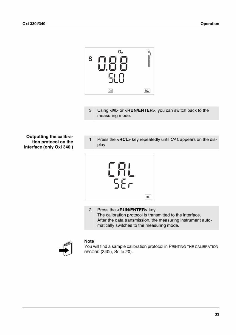
NoteYou will find a sample calibration protocol in PRINTING THE CALIBRATION RECORD (340I), Seite 20).
3 Using <M> or <RUN/ENTER>, you can switch back to the measuring mode.
1 Press the <RCL> key repeatedly until CAL appears on the dis-play.
2 Press the <RUN/ENTER> key. The calibration protocol is transmitted to the interface. After the data transmission, the measuring instrument auto-matically switches to the measuring mode.
dARngConCal
StoreAuto
0No.
LoBat
Day.Month
Year Ident
UpH
AR
%°F°C TP
mV/pHmol/L
TempErrorAutoCal DIN CalError
AutoCal TEC
Time Baud1S
mg/L% ppm
ISE
LC Ars e
RCL

Operation Oxi 330i/340i
34
4.4.4 Clearing the memory
With this function, you can delete stored data records. 500 storage lo-cations will then be available again.
NoteThe Clear memory function only appears when there are data records stored in the memory. Otherwise, the measuring instrument automati-cally switches to the measuring mode.
Proceed as follows to clear all data records:
NoteThe calibration data remain stored and can be called up.
1 Switch off the measuring instrument.
2 Press the <STO> key and hold it down.
3 Press the <ON/OFF> key.The display test appears briefly on the display.Subsequently, Sto clr appears.
4 Confirm the clearing process with <RUN/ENTER>.Pressing any other key prevents the clearing, the data records will remain stored.
RCL
dAuto
Ident
S
1
LoBatTref25nLF
/K%Sal
°
AR
TPC
Mm% mg/l
cmS/cm
cm1/°F
ARngCalLin
Tref20
SalTDS
mbar
OUpHmV/pH
AutoCal DINAutoCal TEC
Time BaudDay.Month No.
Year rS t o
c lStore

Oxi 330i/340i Operation
35
4.5 Transmitting data (only Oxi 340i)
You have the following possibilities of transmitting data:
� One of the following options:
– With the AutoStore function (page 28), measured values are periodically saved internally (save interval Int 1) and output on the interface.
– With the Data transmission interval function (Int 2), measured values are periodically output on the interface (see below).
� With the Output data storage function (page 30), calibration data or saved measured values are output on the interface.
� Via the analog recorder output (page 37), measured values are out-put as voltage values.
� With the KOM pilot communication kit (accessory), data can be transmitted bidirectionally (page 38).
NoteIf you connect a recorder (analog output), the output on the digital in-terface is switched off.
4.5.1 Data transmission interval (Int 2, Oxi 340i)
The interval to the data transmission (Int 2) determines the chronolog-ical interval between automatic data transmissions. After the selected interval expires, the current data record is transmitted to the interface.
NoteWhen the AutoStore function is active, the data transmission is per-formed according to the setting of the save interval (Int 1). Set the save interval (Int 1) to OFF to activate the Data transmission interval (Int 2).
Operation Oxi 330i/340i
36
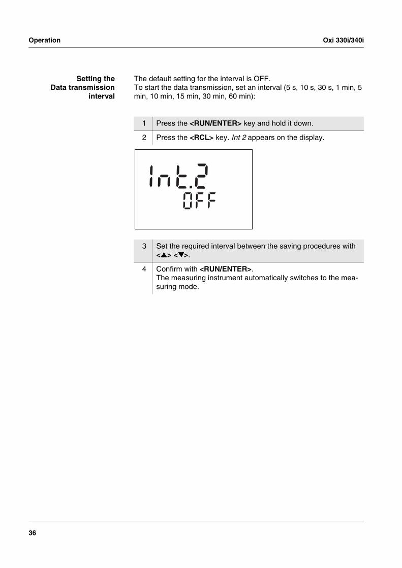
Setting theData transmission
interval
The default setting for the interval is OFF. To start the data transmission, set an interval (5 s, 10 s, 30 s, 1 min, 5 min, 10 min, 15 min, 30 min, 60 min):
1 Press the <RUN/ENTER> key and hold it down.
2 Press the <RCL> key. Int 2 appears on the display.
3 Set the required interval between the saving procedures with <�> <�>.
4 Confirm with <RUN/ENTER>. The measuring instrument automatically switches to the mea-suring mode.
StoreAutoLoBat
Tref25nLF
/K%
RCL
Sal°
AR
TPC
Mm% mg/l
cmS/cm
S
8cm1/
°F
ARngCalLin
Tref20
SalTDS
mbar
OUpHmV/pH
AutoCal DINAutoCal TEC
Time BaudDay.Month No.
IdentYear FFOt 2n1

Oxi 330i/340i Operation
37
4.5.2 Recorder (analog output, Oxi 340i)
You can transmit data to a recorder via the analog output. Connect the analog output to the recorder via the AK323 interface cable. The data output automatically switches to Recorder output.
Socket assignment
NoteThe analog output is activated automatically in the cable by connecting 2 and 3.
The signal range of the analog output depends on the measured vari-able and the measuring range:
Concentration
Saturation
D. O. partial pressure
1 free2 Plug coding3 Ground4 Analog output
1 2
34
RS 232REC
(internal resistance < 5 Ohm)
Measuring range Voltage Resolution
0 ... 19.99 mg/l 0 ... 1999 mV 0.01 mg/l per 1 mV
0 ... 90.0 mg/l 0 ... 900 mV 0.1 mg/l per 1 mV
Measuring range Voltage Resolution
0 ... 199.9 0 ... 1999 mV 0.1 % per 1 mV
0 ... 600 % 0 ... 600 mV 1 % per 1 mV
Measuring range Voltage Resolution
0 ... 199.9 mbar 0 ... 1999 mV 0.1 mbar per 1 mV
0 ... 1250 mbar 0 ... 1250 mV 1 mbar per 1 mV
Operation Oxi 330i/340i
38
4.5.3 PC/external printer (RS232 interface, Oxi 340i)
Via the RS 232 interface, you can transmit the data to a PC or an ex-ternal printer. Use the AK340/B (PC) or AK325/S (ext. printer) cable to connect the interface to the instruments. The data output automatically switches to the RS232 interface.
WarningThe RS232 interface is not galvanically isolated. When connecting an earthed PC/printer, measurements cannot be per-formed in earthed media as incorrect values would result.
Set up the following transmission data on the PC/printer:
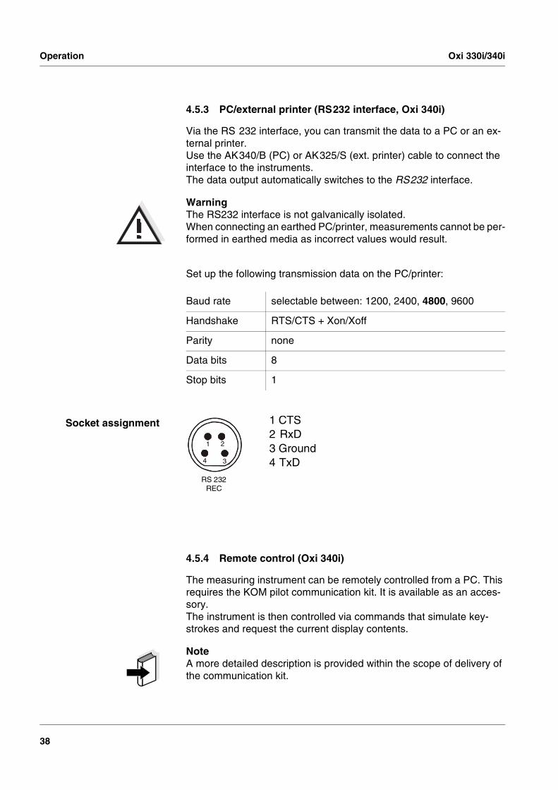
Socket assignment
4.5.4 Remote control (Oxi 340i)
The measuring instrument can be remotely controlled from a PC. This requires the KOM pilot communication kit. It is available as an acces-sory.The instrument is then controlled via commands that simulate key-strokes and request the current display contents.
NoteA more detailed description is provided within the scope of delivery of the communication kit.
Baud rate selectable between: 1200, 2400, 4800, 9600
Handshake RTS/CTS + Xon/Xoff
Parity none
Data bits 8
Stop bits 1
1 CTS2 RxD3 Ground4 TxD
1 2
34
RS 232REC

Oxi 330i/340i Operation
39
4.6 Configuration
You can adapt the measuring instrument to your individual require-ments. To do this, the following parameters can be changed (the status on delivery is marked in bold):
NoteYou can leave the configuration menu at any time with <M> . The pa-rameters that have already been changed are stored.
Baud rate (Oxi 340i)
Baud rate 1200, 2400, 4800, 9600
Air pressure display Current value in mbar (no input possible)
Calibration interval (Int 3) 1 ... 14 ... 999 d
AutoRange ARng On or off
Date/time Any
1 Switch off the measuring instrument.
2 Press the <M> key and hold it down.
3 Press the <ON/OFF> key.The display test appears briefly on the display. The measuring instrument then switches automatically to the setting of the baud rate.
4 Select the required Baud rate with <�> <�>.
5 Confirm with <RUN/ENTER>. The current air pressure in mbar appears on the display.
Day.Month No.Time
1 2 Mm% mg/l
cmS/cm
Smbar
mV/pH
tnStoreAuto
LoBatTref25nLF
/K%
RCL
Sal°
AR
TPCcm1/
°F
ARngCalLin
Tref20
SalTDS OUpH
AutoCal DINAutoCal TEC
IdentYear 0084Baud

Operation Oxi 330i/340i
40
Displaying the airpressure
Calibration interval
AutoRange (automaticselection of the mea-
surement range)
6 Confirm with <RUN/ENTER>. Int 3 appears on the display.
Baud
4Day.Month No.Time
1 Mm% mg/l
cmS/cm
S mV/pH
tnStoreAuto
LoBatTref25nLF
/K%
RCL
Sal°
AR
TPCcm1/
°F
ARngCalLin
Tref20
SalTDS OUpH
AutoCal DINAutoCal TEC
IdentYear 949mbarP
7 Set the required interval in days with <�> <�>.
8 Confirm with <RUN/ENTER>.ARng appears on the display.
°C1 TP
ARng
mg/l
LoBat
BaudDay.Month No.
IdentYear
Sal
%
mbar
S
RCLARStoreAuto
°F1/cm
/K%
TDS UpH SalmV/pH
S/m cmcmM
Lin
Tref25 Tref20
nLF
AutoCal DINAutoCal TEC
41t 3n
O
1d
Time
Cal
9 Using <�> <�>, switch between no and YES.YES: Switch on AutoRange.no: Switch off AutoRange.
10 Confirm with <RUN/ENTER>.on the display.
Sal/K% TPC°°F
Store
cm1/1S
Mm% mg/l
cmS/cm
mV/pH
mbarBaud
4Day.Month No.Time
AutoLoBat
Tref25nLF RCLARCalLin
Tref20
SalTDS UpH
AutoCal DINAutoCal TEC
IdentYear SEYARng
nrAO

Oxi 330i/340i Operation
41
Date and time
11 Set the date of the current day with <�> <�>.
12 Confirm with <RUN/ENTER>.The date (month) flashes in the display.
13 Set the current month with <�> <�>.
14 Confirm with <RUN/ENTER>.The year appears on the display.
15 Set the current year with <�> <�>.
16 Confirm with <RUN/ENTER>.The hours flash on the display.
17 Set the current time with <�> <�>.
18 Confirm with <RUN/ENTER>.The minutes flash on the display.
19 Set the current time with <�> <�>.
20 Confirm with <RUN/ENTER>.The measuring instrument automatically switches to the mea-suring mode.
S
1 Mm% mg/l
cmS/cm
mbar
mV/pH
D i sStoreAuto
Ident
LoBatTref25nLF
/K%Sal
°
AR
TPCcm1/
°F
ARngCalLin
Tref20
SalTDS OUpH
AutoCal DINAutoCal TEC
Time BaudNo.
Year 4090Day.Month
Operation Oxi 330i/340i
42
4.7 Reset
You can reset (initialize) the measurement parameters and the config-uration parameters separately from one another.
Measurementparameters
The following measured parameters (O2 InI) are reset to the default condition:
NoteThe calibration data gets lost when the measuring parameters are re-set. Recalibrate after performing a reset.
Configurationparameters
The following configuration parameters (InI) are reset to the delivery status:
Resetting themeasuring parameters
Measuring mode D. O. concentration
AutoRange automatic measure-ment range selection
On (YES)
Relative slope 1.00
Correction factor of the relative slope
1.000
Salinity equivalent 0.0
Salt content correction off
Baud rate 4800
Interval 1(automatic save) OFF
Interval 2(for data transmission) OFF
1 Press the <RUN/ENTER> key and hold it down.
2 Press the <CAL> key.

Oxi 330i/340i Operation
43
Resetting the configura-tion parameters
3 Using <�> <�>, switch between no and YES.YES: Resetting the measuring parametersno: Retaining settings.
4 Confirm with <RUN/ENTER>.The measuring instrument switches to the configuration pa-rameters.
UpH
ARng
Y
Sal
Sal/K% TPC°°F
Store
cm1/1S
Mm% mg/l
cmS/cm
mV/pH
mbarBaud
4Day.Month No.Time
AutoLoBat
Tref25nLF RCLARCalLin
Tref20
TDS
AutoCal DINAutoCal TEC
IdentYear onInI
O
OUpH
ARng
Y
Sal
Sal/K% TPC°°F
Store
cm1/1S
Mm% mg/l
cmS/cm
mV/pH
mbarBaud
4Day.Month No.Time
AutoLoBat
Tref25nLF RCLARCalLin
Tref20
TDS
AutoCal DINAutoCal TEC
IdentYear onInI
5 Using <�> <�>, switch between no and YES.YES: Resetting the configuration parametersno: Retaining settings.
6 Confirm with <RUN/ENTER>.The measuring instrument automatically switches to the mea-suring mode.

Operation Oxi 330i/340i
44

Oxi 330i/340i Maintenance, cleaning, disposal
45
5 Maintenance, cleaning, disposal
5.1 Maintenance
The measuring instrument is almost maintenance-free. The only maintenance task is replacing the batteries.LoBat indicates that the batteries should be changed. The batteries are then largely depleted.
Replacing the batteries
WarningMake sure that the poles of the batteries are the right way round.The ± signs on the batteries must correspond to the ± signs in the bat-tery compartment. Only use leakproof alkaline manganese batteries.
1 Open the housing after the instrument has been switched off:– Undo the four screws on the underside of the instrument
– Pull down the lower cover (1).
2 If necessary, take the four depleted batteries (2) out of the bat-tery compartment.
3 Place four new batteries (type Mignon AA) in the battery com-partment.
4 Close the lower cover (1).
1
2

Maintenance, cleaning, disposal Oxi 330i/340i
46
NoteFor the maintenance of the sensors, follow the corresponding operating manual.
5.2 Cleaning
Occasionally wipe the outside of the measuring instrument with a damp, lint-free cloth. Disinfect the housing with isopropanol as re-quired.
WarningThe housing is made of a synthetic material (ABS). Thus, avoid contact with acetone and similar detergents that contain solvents. Remove any splashes immediately.
5.3 Disposal
Packing This measuring instrument is sent out in a protective transport packing. We recommend: Keep the packing material. The original packing pro-tects the instrument against damage during transport.
Batteries This note refers to the battery regulation that applies in the Federal Re-public of Germany. We would ask end-consumers in other countries to follow their local statutory provisions.
NoteThis instrument contains batteries. Batteries that have been removed must only be disposed of at the recycling facility set up for this purpose or via the retail outlet. It is illegal to dispose of them in household refuse.
Measuring instrument Dispose of the measuring instrument as electronic waste at an appro-priate collection point. It is illegal to dispose of the instrument in house-hold refuse.
Oxi 330i/340i What to do if...
47
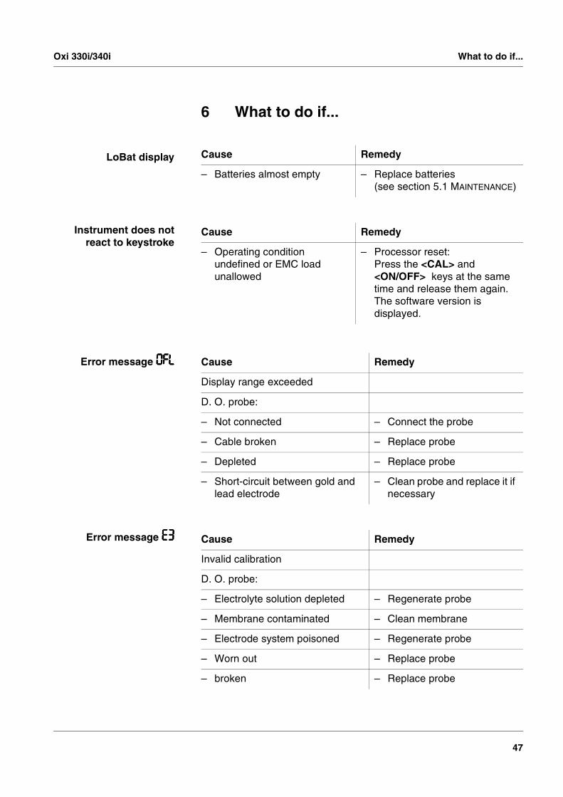
6 What to do if...
LoBat display
Instrument does notreact to keystroke
Error message 0FL0FL0FL0FL
Error message E3E3E3E3
Cause Remedy
– Batteries almost empty – Replace batteries(see section 5.1 MAINTENANCE)
Cause Remedy
– Operating condition undefined or EMC load unallowed
– Processor reset:Press the <CAL> and <ON/OFF> keys at the same time and release them again. The software version is displayed.
Cause Remedy
Display range exceeded
D. O. probe:
– Not connected – Connect the probe
– Cable broken – Replace probe
– Depleted – Replace probe
– Short-circuit between gold and lead electrode
– Clean probe and replace it if necessary
Cause Remedy
Invalid calibration
D. O. probe:
– Electrolyte solution depleted – Regenerate probe
– Membrane contaminated – Clean membrane
– Electrode system poisoned – Regenerate probe
– Worn out – Replace probe
– broken – Replace probe
What to do if... Oxi 330i/340i
48
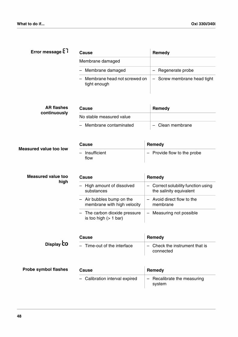
Error message E7E7E7E7
AR flashescontinuously
Measured value too low
Measured value toohigh
Display totototo
Probe symbol flashes
Cause Remedy
Membrane damaged
– Membrane damaged – Regenerate probe
– Membrane head not screwed on tight enough
– Screw membrane head tight
Cause Remedy
No stable measured value
– Membrane contaminated – Clean membrane
Cause Remedy
– Insufficient flow
– Provide flow to the probe
Cause Remedy
– High amount of dissolved substances
– Correct solubility function using the salinity equivalent
– Air bubbles bump on the membrane with high velocity
– Avoid direct flow to the membrane
– The carbon dioxide pressure is too high (> 1 bar)
– Measuring not possible
Cause Remedy
– Time-out of the interface – Check the instrument that is connected
Cause Remedy
– Calibration interval expired – Recalibrate the measuring system

Oxi 330i/340i What to do if...
49
Message StoFullStoFullStoFullStoFull
You would like to knowwhich software version
is in the instrument
Cause Remedy
– All memory locations are full – Output data storage and clear data storage
Cause Remedy
– e.g. question of the WTW service department
– Press the <CAL> and <ON/OFF> keys at the same time and release them again. The software version is displayed.

What to do if... Oxi 330i/340i
50

Oxi 330i/340i Technical data
51
7 Technical data
Dimensions and weight
Mechanical structure
Electrical safety
Test certificates
Ambient conditions
Measuring ranges/resolutions with
CellOx 325 D. O. probe
Measuring ranges/resolutions with
DurOx 325 D. O. probe
Measuring range/resolu-tion of temperature
Length [mm] 172
Width [mm] 80
Height [mm] 37
Weight [kg] Approx. 0.3
Type of protection IP 66
Protective class III
GS, cETLus, CE
Storage - 25 °C ... + 65 °C
Operation -10 °C ... + 55 °C
Climatic class 2
mg/l % mbar
Measuring range I Resolution
0 ... 19.990.01
0 ... 199.90.1
0 ... 199.90.1
Measuring range II Resolution
0 ... 90.0 0.1
0 ... 6001
0 ... 12501
mg/l % mbar
Measuring range I Resolution
0 ... 19.90.1
0 ... 1991
0 ... 1991
Measuring range II Resolution
0 ... 901
0 ... 6001
0 ... 12501
°C
Measuring range (Resolution) 0 ... 50.0 (0.1)
Technical data Oxi 330i/340i
52
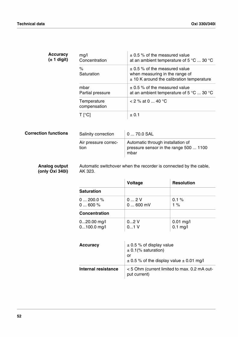
Accuracy(± 1 digit)
Correction functions
Analog output(only Oxi 340i)
Automatic switchover when the recorder is connected by the cable, AK 323.
mg/lConcentration
± 0.5 % of the measured valueat an ambient temperature of 5 °C ... 30 °C
%Saturation
± 0.5 % of the measured valuewhen measuring in the range of ± 10 K around the calibration temperature
mbarPartial pressure
± 0.5 % of the measured valueat an ambient temperature of 5 °C ... 30 °C
Temperature compensation
< 2 % at 0 ... 40 °C
T [°C] ± 0.1
Salinity correction 0 ... 70.0 SAL
Air pressure correc-tion
Automatic through installation of pressure sensor in the range 500 ... 1100 mbar
Voltage Resolution
Saturation
0 ... 200.0 %0 ... 600 %
0 ... 2 V0 ... 600 mV
0.1 %1 %
Concentration
0...20.00 mg/l0...100.0 mg/l
0...2 V0...1 V
0.01 mg/l0.1 mg/l
Accuracy ± 0.5 % of display value± 0.1(% saturation)or± 0.5 % of the display value ± 0.01 mg/l
Internal resistance < 5 Ohm (current limited to max. 0.2 mA out-put current)

Oxi 330i/340i Technical data
53
Serial interface (onlyOxi 340i)
Automatic switchover when a PC or a printer is connected via the cable, AK 340/B or AK 325/S.
Power supply
Type RS 232, data output
Baud rate Selectable 1200, 2400, 4800, 9600 baud
Data bits 8
Stop bit 2
Parity None
Handshake RTS/CTS + Xon/Xoff
Cable length Max. 15m
Batteries 4 x 1.5 V alkali-manganese batteries, Type AA
Operational life Approx. 3000 operating hours
Mains (only Oxi 340i) The following specifications apply to all plug-in power supplies: Connection max. Overvoltage category IIPlug-in power supply with Euro plug:FRIWO FW1199, 11.7864Friwo Part. No. 1762613Input: 230 V ~ / 50 Hz / 5.6 VAOutput: 12 V = / 130 mA / 1.56 VA
Plug-in power supply with US plug:FRIWO FW1199, 11.7880Friwo Part. No. 1794043Input: 120 V ~ / 60 Hz / 6 VAOutput: 12 V = / 150 mA
Plug-in power supply with UK plug:FRIWO FW1199, 11.7872Friwo Part No. 1816491Input: 230V ~ / 50 Hz / 5.6 VAOutput: 12 V = / 130 mA / 1.56 VA
Technical data Oxi 330i/340i
54
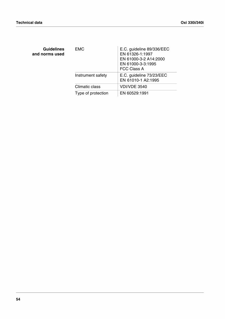
Guidelinesand norms used
EMC E.C. guideline 89/336/EECEN 61326-1:1997EN 61000-3-2 A14:2000EN 61000-3-3:1995FCC Class A
Instrument safety E.C. guideline 73/23/EECEN 61010-1 A2:1995
Climatic class VDI/VDE 3540
Type of protection EN 60529:1991
Oxi 330i/340i Lists
55
8 Lists
This chapter provides additional information and orientation aids.
Abbreviations The list of abbreviations explains the indicators and the abbreviations that appear on the display and in the manual.
Specialist terms The glossary briefly explains the meaning of the specialist terms. How-ever, terms that should already be familiar to the target group are not described here.
Index The index will help you to find the topics that you are looking for.
Lists Oxi 330i/340i
56
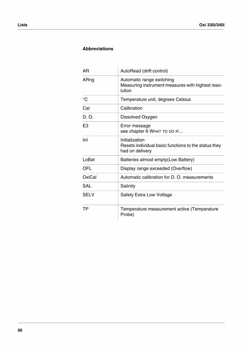
Abbreviations
AR AutoRead (drift control)
ARng Automatic range switchingMeasuring instrument measures with highest reso-lution
°C Temperature unit, degrees Celsius
Cal Calibration
D. O. Dissolved Oxygen
E3 Error message see chapter 6 WHAT TO DO IF...
InI InitializationResets individual basic functions to the status they had on delivery
LoBat Batteries almost empty(Low Battery)
OFL Display range exceeded (Overflow)
OxiCal Automatic calibration for D. O. measurements
SAL Salinity
SELV Safety Extra Low Voltage
TP Temperature measurement active (Temperature Probe)

Oxi 330i/340i Lists
57
Glossary
Adjusting To manipulate a measuring system so that the relevant value (e. g. the displayed value) differs as little as possible from the correct value or a value that is regarded as correct, or that the difference remains with-in the tolerance.
Amperometry Name of a measuring technique. The signal (depending on the mea-sured parameter) of the probe is the electric current. The electrical voltage remains constant.
AutoRange Name of the automatic selection of the measuring range.
AutoRead WTW name for a function to check the stability of the measured value.
Calibration Comparing the value from a measuring system (e. g. the displayed value) to the correct value or a value that is regarded as correct. Of-ten, this expression is also used when the measuring system is adjust-ed at the same time (see adjusting).
D. O. partial pressure Pressure caused by the oxygen in a gas mixture or liquid.
D. O. saturation Short name for the relative D. O. saturation. Note: The D. O. saturation value of air-saturated water and the D. O. saturation value of oxygen-saturated water are different.
Measured parameter The measured parameter is the physical dimension determined by measuring, e. g. pH, conductivity or D. O. concentration.
Measured value The measured value is the special value of a measured parameter to be determined. It is given as a combination of the numerical value and unit (e. g. 3 m; 0.5 s; 5.2 A; 373.15 K).
Measuring system The measuring system comprises all the devices used for measuring, e. g. measuring instrument and probe. In addition, there is the cable and possibly an amplifier, terminal strip and armature.
Molality Molality is the quantity (in Mol) of a dissolved substance in 1000 g sol-vent.
OxiCal® WTW name for a procedure to calibrate D. O. measuring systems in water vapor saturated air.
Reset Restoring the original condition of all settings of a measuring system.
Resolution Smallest difference between two measured values that can be dis-played by a measuring instrument.

Lists Oxi 330i/340i
58
Salinity The absolute salinity SA of seawater corresponds to the relationship of the mass of dissolved salts to the mass of the solution (in g/Kg). In practice, this dimension cannot be measured directly. Therefore, the practical salinity is used for oceanographic monitoring. It is deter-mined by measuring the electrical conductivity.
Salt content General designation for the quantity of salt dissolved in water.
Slope The slope of a linear calibration function.
Slope (relative) Designation used by WTW in the D. O. measuring technique. It ex-presses the relationship of the slope value to the value of a theoretical reference probe of the same type of construction.
Standard solution The standard solution is a solution where the measured value is known by definition. It is used to calibrate a measuring system.
Test sample Designation of the sample ready to be measured. Normally, a test sample is made by processing the original sample. The test sample and original sample are identical if the test sample was not processed.
Oxi 330i/340i Index
59
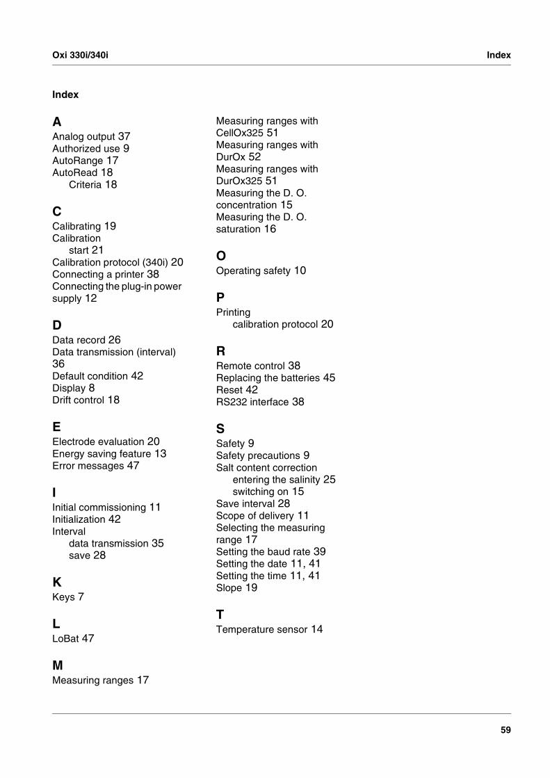
Index
AAnalog output 37Authorized use 9AutoRange 17AutoRead 18
Criteria 18
CCalibrating 19Calibration
start 21Calibration protocol (340i) 20Connecting a printer 38Connecting the plug-in power supply 12
DData record 26Data transmission (interval) 36Default condition 42Display 8Drift control 18
EElectrode evaluation 20Energy saving feature 13Error messages 47
IInitial commissioning 11Initialization 42Interval
data transmission 35save 28
KKeys 7
LLoBat 47
MMeasuring ranges 17
Measuring ranges with CellOx325 51Measuring ranges with DurOx 52Measuring ranges with DurOx325 51Measuring the D. O. concentration 15Measuring the D. O. saturation 16
OOperating safety 10
PPrinting
calibration protocol 20
RRemote control 38Replacing the batteries 45Reset 42RS232 interface 38
SSafety 9Safety precautions 9Salt content correction
entering the salinity 25switching on 15
Save interval 28Scope of delivery 11Selecting the measuring range 17Setting the baud rate 39Setting the date 11, 41Setting the time 11, 41Slope 19
TTemperature sensor 14

Index Oxi 330i/340i
60