Embed Size (px)
Citation preview

cod. 1-5302-858
WORKSHOP MANUAL1003 FOCS Engine Series


- 3 -
PREFACE
- Every attempt has been made to present within this service manual, accurate and up to date technicalinformation.However, development on the LOMBARDINI series is continuous.Therefore, the information within this manual is subject to change without notice and without obligation.
- The information contained within this service manual is the sole property of LOMBARDINI.As such, no reproduction or replication in whole or part is allowed without the express written permission ofLOMBARDINI.
Information presented within this manual assumes the following:
1 - The person or people performing service work on LOMBARDINI series engines is properly trained andequipped to safely and professionally perform the subject operation;
2 - The person or people performing service work on LOMBARDINI series engines possesses adequate hand andLOMBARDINI special tools to safely and professionally perform the subject service operation;
3 - The person or people performing service work on LOMBARDINI series engines has read the pertinentinformation regarding the subject service operations and fully understands the operation at hand.
- This manual was written by the manufacturer to provide technical and operating information to authorisedLOMBARDINI after-sales service centres to carry out assembly, disassembly, overhauling, replacement andtuning operations.
- As well as employing good operating techniques and observing the right timing for operations, operators must readthe information very carefully and comply with it scrupulously.
- Time spent reading this information will help to prevent health and safety risks and financial damage.Written information is accompanied by illustrations in order to facilitate your understanding of every step of theoperating phases.
1003 FOCSEngine Series
FOCS Workshop Manual_cod. 1.5302.858_1° ed_ rev. 00

- 4 - FOCS Workshop Manual_cod. 1.5302.858_1° ed_ rev. 00
-
CUSE/ATLO1 31.10.20080 31.10.20081-5302-858 51199
Draftingbody
Documentcode Edition Issue date
Reviewdate
ModelN° Revision
REGISTRATION OF MODIFICATIONS TO THE DOCUMENT
Any modifications to this document must be registered by the drafting body, by completing the following table.
Endorsed

- 5 -FOCS Workshop Manual_cod. 1.5302.858_1° ed_ rev. 00
-
CHAPTER INDEX
1 GENERAL REMARKS AND SAFETY INFORMATION .................................................................. Pag. 9-11
GENERAL SAFETY DURING OPERATING PHASES .................................................................................................... 11GENERAL SERVICE MANUAL NOTES ............................................................................................................................ 9GLOSSARY AND TERMINOLOGY ................................................................................................................................... 9SAFETY AND ENVIRONMENTAL IMPACT ....................................................................................................................11SAFETY AND WARNING DECALS ................................................................................................................................. 10SAFETY REGULATIONS ........................................................................................................................................... 10-11WARRANTY CERTIFICATE............................................................................................................................................... 9
2 TECHNICAL INFORMATION .................................................................................................................. 12-17
MANUFACTURER AND ENGINE IDENTIFICATION ................................................................................................ 14-15PERFORMANCE DIAGRAMS .......................................................................................................................................... 16TECHINICAL SPECIFICATIONS ..................................................................................................................................... 17TROUBLE SHOOTING ............................................................................................................................................... 12-13
3 MAINTENANCE - RECOMMENDED OIL TYPE - REFILLING .............................................................. 18-21
ACEA Regualtions - ACEA Sequences ............................................................................................................................ 19API / MIL Sequence .......................................................................................................................................................... 19COOLANT ......................................................................................................................................................................... 21FUEL RECOMMENDATIONS .......................................................................................................................................... 21International specifications ............................................................................................................................................... 19LUBRICANT ...................................................................................................................................................................... 19PRESCRIBED LUBRICANT ............................................................................................................................................. 20ROUTINE ENGINE MAINTENANCE ............................................................................................................................... 18SAE Classification ........................................................................................................................................................... 19
4 DISASSEMBLY / REASSEMBLY ........................................................................................................... 22-53
Alternator/Cooling fan belt drive ....................................................................................................................................... 25Big end bearing ................................................................................................................................................................. 46Camshaft ........................................................................................................................................................................... 36Camshaft journals and housings - Dimensions (mm) ..................................................................................................... 36Camshaft lobe measurement ........................................................................................................................................... 36Camshaft timing ................................................................................................................................................................ 28Camshaft timing - Belt Reassembly ................................................................................................................................28Camshaft timing - Belt Tightening and Fastening ........................................................................................................... 29Camshaft timing - Belt tightening tool ............................................................................................................................. 29Camshaft timing pulley ..................................................................................................................................................... 28Camshaft timing pulley - Disassembly/Assembly ........................................................................................................... 28Camshaft timing pulley - Reference marks ..................................................................................................................... 28Camshaft, disassembly .................................................................................................................................................... 36Camshaft, journal and housing measurement ................................................................................................................ 36Central main bearing caps ............................................................................................................................................... 48Check the clearances between the bearings and the journal .......................................................................................... 48Clearances between the bearings and corresponding pins ............................................................................................51CONNECTING ROD ......................................................................................................................................................... 46Connecting rod alignment ................................................................................................................................................ 47Connecting rod with bearings and pin ............................................................................................................................. 46Connecting tod, weight ..................................................................................................................................................... 46Crankcase vacuum regulator valve .................................................................................................................................. 33Crankshaft axial clearance ............................................................................................................................................... 49Crankshaft front and back oil seal rings ..........................................................................................................................50Crankshaft timing pulley ................................................................................................................................................... 28Crankshaft, check journals and crank .............................................................................................................................. 50Crankshaft, lubrication lines ............................................................................................................................................. 50Cylinder head assembly ................................................................................................................................................... 45
This manual contains pertinent information regarding the repair of LOMBARDINI water-cooled, indirect injection Dieselengines type LDW 1003: updated October 31st, 2008.
CHAPTER INDEX

- 6 - FOCS Workshop Manual_cod. 1.5302.858_1° ed_ rev. 00
-
Cylinder head tightening procedure ................................................................................................................................. 45Cylinder head, removal ..................................................................................................................................................... 37Cylinder roughness ........................................................................................................................................................... 47Cylinder, class ...................................................................................................................................................................47CYLINDERS ...................................................................................................................................................................... 47Driving pulley ....................................................................................................................................................................26E.G.R. Circuit ....................................................................................................................................................................23E.G.R. Circuit - Disassembly/Reassembly ...................................................................................................................... 24Exhaust manifold ..............................................................................................................................................................25Flywheel ............................................................................................................................................................................ 26Fuel rail ............................................................................................................................................................................. 34Governor springs ..............................................................................................................................................................31Head gasket ...................................................................................................................................................................... 44Injection pump control rod ................................................................................................................................................ 34Intake manifold – Remote air filter ................................................................................................................................... 23Intake, exhaust, injection camshaft lobe height ..............................................................................................................37Journal and connecting rod pins diameters ..................................................................................................................... 51Main bearings and connecting rod big ends diameters ..................................................................................................51Oil pan, removal ............................................................................................................................................................... 41Oil pump - Disassembly/Reassembly .............................................................................................................................. 32PISTON ............................................................................................................................................................................. 42Piston clearance ............................................................................................................................................................... 44Piston ring, Clearance between grooves (mm) ............................................................................................................... 43Piston ring, mounting order .............................................................................................................................................. 43Piston rings - End gaps (mm) .......................................................................................................................................... 43Piston supply ..................................................................................................................................................................... 42Piston, assembly ............................................................................................................................................................... 44Piston, class ...................................................................................................................................................................... 42Piston, disassembly and inspection ................................................................................................................................. 42Piston, weight ....................................................................................................................................................................43Pre-combustion chamber .................................................................................................................................................40Pre-combustion chamber ring nut removal ..................................................................................................................... 40Pre-combustion chamber, installation ............................................................................................................................. 41Pre-combustion chamber, removal .................................................................................................................................. 41Pump/injector unit - Disassembly .................................................................................................................................... 35Pump/injector unit - non-return valve ............................................................................................................................... 34Rear and forward main bearing caps ............................................................................................................................... 48RECOMMENDATIONS FOR DISASSEMBLING AND ASSEMBLING ........................................................................... 22RECOMMENDATIONS FOR OVERHAULS AND TUNING ............................................................................................22Rocker arm assembly .......................................................................................................................................................35Rocker arm cover ..............................................................................................................................................................32Rocker arm cover gasket ..................................................................................................................................................33Rocker arm pivot, dismounting and remounting ............................................................................................................. 35Shoulder half rings ............................................................................................................................................................ 49Shoulder half rings, oversized elements ..........................................................................................................................49Speed governor ................................................................................................................................................................. 30Speed governor - Limiting speed governor ...................................................................................................................... 31Speed governor - Reassembly ......................................................................................................................................... 31Speed governor components ...........................................................................................................................................30Stop pin rings, dismounting and remounting ................................................................................................................... 42Tightening pulley ............................................................................................................................................................... 27Timing belt / Timing pulley arrangement ......................................................................................................................... 27Timing belt cover ..............................................................................................................................................................27Timing belt removal .......................................................................................................................................................... 27Vacuum pump and vacuum pump flange ........................................................................................................................ 25Valve / Rocker arm clearance .......................................................................................................................................... 33Valve guide insertion ........................................................................................................................................................39Valve guides and valve guide housings ........................................................................................................................... 39Valve recess and seat sealing width ................................................................................................................................40Valve seats and housings - .............................................................................................................................................. 40Valve springs ..................................................................................................................................................................... 38Valve stem sealing rings - Reassembly ........................................................................................................................... 38Valve timing - Angles ........................................................................................................................................................30Valve timing check ............................................................................................................................................................ 29Valve, specifications ......................................................................................................................................................... 39Valves ................................................................................................................................................................................38
Chapter index

- 7 -FOCS Workshop Manual_cod. 1.5302.858_1° ed_ rev. 00
-
5 LUBRIFICATION CIRCUIT ..................................................................................................................... 54-57
Internal oil filter and oil sump return pipe ........................................................................................................................ 55Oil filter cartridge ..............................................................................................................................................................56Oil pressure check ............................................................................................................................................................ 56Oil pressure regulating valve ............................................................................................................................................56Oil pump ............................................................................................................................................................................ 55Oil pump, clearance between rotors ................................................................................................................................55
6 COOLANT CIRCUIT ............................................................................................................................... 58-59
COOLANT CIRCUIT ......................................................................................................................................................... 58Coolant circulation pump, components ........................................................................................................................... 59Radiator and compensation, check and seal tank cap. ..................................................................................................59Thermostatic valve ............................................................................................................................................................ 59
7 FUEL SYSTEM ....................................................................................................................................... 60-67
Fuel feeding / injection circuit ........................................................................................................................................... 60Fuel filter detached from the tank (on request) ............................................................................................................... 60Fuel lift pump ....................................................................................................................................................................60Fuel pump drive rod projection - Assembly ..................................................................................................................... 60Injection advance ..............................................................................................................................................................65Injection advance control and regulation ......................................................................................................................... 65Injection pump assembly/disassembly ............................................................................................................................ 62Injection pumps delivery balancing .................................................................................................................................. 67Injector, nozzle projection ................................................................................................................................................. 64Injector, spark arrester ...................................................................................................................................................... 64Instrument connection ...................................................................................................................................................... 66Plunger barrel ring nut assembly/disassembly ................................................................................................................ 62Plunger injection pump reassembly ................................................................................................................................. 62Preliminary steps to pump/injector unit delivery balancing test ..................................................................................... 66Pump/injector unit ............................................................................................................................................................. 61Pump/injector unit se.no. 6590.290 control data. ........................................................................................................... 63Pump/injector unit, components ......................................................................................................................................61Pumping element ..............................................................................................................................................................62Setting of injector ..............................................................................................................................................................64Static injection advance tuning ........................................................................................................................................ 66Test head B assembly ...................................................................................................................................................... 66
8 ELECTRIC SYSTEM ............................................................................................................................... 68-73
Alternator, 14V 33A ......................................................................................................................................................... 68Alternator, 14V 33A - Performance Curve ...................................................................................................................... 68Coolant high temperature lamp sensor ............................................................................................................................ 72Electric starting layout (12V) with alternator 14V 33A ................................................................................................... 69Oil pressure switch ........................................................................................................................................................... 72Pre-heating glow plug ....................................................................................................................................................... 70Pre-heating plug control unit with coolant temperature sensor ......................................................................................71Pre-heating water temperature thermistor and Water temperature indicator thermal contact ......................................72STARTER MOTOR - Bosch DW 12V 1,1 KW ................................................................................................................ 70Starter motor, Bosch DW 12V 1,1 KW - Performance Curve ........................................................................................ 70Temperature sensor for control unit ................................................................................................................................. 71Wiring diagram for pre-heating gear case ....................................................................................................................... 71
9 SETTINGS ............................................................................................................................................... 74-77
E.G.R. calibration ............................................................................................................................................................. 77Injection pump flow limiter and engine torque gearing device ........................................................................................ 75Pump injection delivery setting ........................................................................................................................................ 75Pump injection delivery standard setting without dynamometric brake ......................................................................... 75Pump/injector unit delivery setting with braked engine ................................................................................................... 76
Chapter index

- 8 - FOCS Workshop Manual_cod. 1.5302.858_1° ed_ rev. 00
- Chapter index
Pump/injector unit timing with speed governor ............................................................................................................... 74Required settings (as most commonly applies) ..............................................................................................................76Setting the idle maximum (standard) ............................................................................................................................... 74Setting the idle minimum (standard) ................................................................................................................................74Setting the stop ................................................................................................................................................................. 74SPEED SETTINGS ........................................................................................................................................................... 74
10 STORAGE ............................................................................................................................................... 78-79
ENGINE STORAGE .......................................................................................................................................................... 78PREPARING THE ENGINE FOR OPERATION AFTER PROTECTIVE TREATMENT ................................................. 79PROTECTIVE TREATMENT ............................................................................................................................................78
11 TORQUE SPECIFICATIONS AND USE OF SEALANT ....................................................................... 80-81
Table of tightening torques for standard screws (coarse thread) ................................................................................... 81Table of tightening torques for standard screws (fine thread) ........................................................................................ 81Table of tightening torques for the main components ..................................................................................................... 80
12 SPECIAL TOOLS ......................................................................................................................................... 82

- 9 -FOCS Workshop Manual_cod. 1.5302.858_1° ed_ rev. 00
1
- The products manufactured by LOMBARDINI S.r.l. are warranted to be free from conformity defects for a period of 24 monthsfrom the date of delivery to the first end user.
- For engines fitted to stationary equipment, working at constant load and at constant and/or slightly variable speed within thesetting limits, the warranty covers a period up to a limit of 2000 working hours, if the above mentioned period (24 months) isnot expired.
- If no hour-meter is fitted , 12 working hours per calendar day will be considered.- For what concerns the parts subject to wear and deterioration (injection/feeding system, electrical system, cooling system,
sealing parts, non-metallic pipes, belts) warranty covers a maximum limit of 2000 working hours, if the above mentioned period(24 months) is not expired.
- For correct maintenance and replacement of these parts, it is necessary to follow the instructions reported in the documentationsupplied with each engine.
- To ensure the engine warranty is valid, the engine installation, considering the product technical features, must be carried outby qualified personnel only.
- The list of the LOMBARDINI S.r.l. authorized dealers is reported in the “Service” booklet, supplied with each engine.- Special applications involving considerable modifications to the cooling/lubricating system (for ex.: dry oil sump), filtering
system, turbo-charged models, will require special written warranty agreements.- Within the above stated periods LOMBARDINI S.r.l. directly or through its authorized network will repair and/or replace free
of charge any own part or component that, upon examination by LOMBARDINI S.r.l. or by an authorized LOMBARDINI S.r.l.agent, is found to be defective in conformity, workmanship or materials.
- Any other responsibility/obligation for different expenses, damages and direct/indirect losses deriving from the engine use orfrom both the total or partial impossibility of use, is excluded.
- The repair or replacement of any component will not extend or renew the warranty period.
LOMBARDINI S.r.l. warranty obligations here above described will be cancelled if:
- LOMBARDINI S.r.l. engines are not correctly installed and as a consequence the correct functional parameters are notrespected and altered.
- LOMBARDINI S.r.l. engines are not used according to the instructions reported in the “Use and Maintenance” bookletsupplied with each engine.
- Any seal affixed to the engine by LOMBARDINI S.r.l. has been tampered with or removed.- Spare parts used are not original LOMBARDINI S.r.l..- Feeding and injection systems are damaged by unauthorized or poor quality fuel types.- Electrical system failure is due to components, connected to this system, which are not supplied or installed by
LOMBARDINI S.r.l..- Engines have been disassembled, repaired or altered by any part other than an authorized LOMBARDINI agent.
- Following expiration of the above stated warranty periods and working hours, LOMBARDINI S.r.l. will have no furtherresponsibility for warranty and will consider its here above mentioned obligations for warranty complete.
- Any warranty request related to a non-conformity of the product must be addressed to the LOMBARDINI S.r.l. service agents.
GENERAL SERVICE MANUAL NOTES
1 - Use only genuine LOMBARDINI S.r.l. repair parts.Failure to use genuine LOMBARDINI S.r.l. parts could result in sub-standard performance and low longevity.
2 - All data presented are in metric format. That is, dimensions are presented in millimeters (mm), torque is presented inNewton-meters (Nm), weight is presented in kilograms (Kg), volume is presented in liters or cubic centimeters (cc) andpressure is presented in barometric units (bar).
GENERAL REMARKS AND SAFETY INFORMATION
WARRANTY CERTIFICATE
GLOSSARY AND TERMINOLOGY
For clarity, here are the definitions of a number of terms used recurrently in the manual.
- Cylinder number one: is the flywheel side piston .- Rotation direction: anticlockwise «viewed from the flywheel side of the engine».

- 10 - FOCS Workshop Manual_cod. 1.5302.858_1° ed_ rev. 00
1
− LOMBARDINI Engines are built to supply their performances in a safe and long-lasting way.To obtain these results, it is essential for users to comply with the servicing instructions given in the relative manual along withthe safety recommendations listed below.
− The engine has been made according to a machine manufacturer's specifications and all actions required to meet the essentialsafety and health safeguarding requisites have been taken, as prescribed by the current laws in merit.All uses of the engine beyond those specifically established cannot therefore be considered as conforming to the use definedby LOMBARDINI which thus declines all liability for any accidents deriving from such operations.
− The following indications are dedicated to the user of the machine in order to reduce or eliminate risks concerning engineoperation in particular, along with the relative routine maintenance work.
− The user must read these instructions carefully and become familiar with the operations described.Failure to do this could lead to serious danger for his personal safety and health and that of any persons who may be in thevicinity of the machine.
• The engine may only be used or assembled on a machine by technicians who are adequately trained about its operation andthe deriving dangers.This condition is also essential when it comes to routine and, above all, extraordinary maintenance operations which, in thelatter case, must only be carried out by persons specifically trained by LOMBARDINI and who work in compliance with theexisting documentation.
− Variations to the functional parameters of the engine, adjustments to the fuel flow rate and rotation speed, removal of seals,demounting and refitting of parts not described in the operation and maintenance manual by unauthorized personnel shallrelieve LOMBARDINI from all and every liability for deriving accidents or for failure to comply with the laws in merit.
− On starting, make sure that the engine is as horizontal as possible, unless the machine specifications differ.In the case of manual start-ups, make sure that the relative actions can take place without the risk of hitting walls or dangerousobjects, also considering the movements made by the operator.Pull-starting with a free cord (thus excluding self-winding starting only), is not permitted even in an emergency.
− Make sure that the machine is stable to prevent the risk of overturning.− Become familiar with how to adjust the rotation speed and stop the engine.− Never start the engine in a closed place or where there is insufficient ventilation.
Combustion creates carbon monoxide, an odourless and highly poisonous gas.Lengthy stays in places where the engine freely exhausts this gas can lead to unconsciousness and death.
− The engine must not operate in places containing inflammable materials, in explosive atmospheres, where there is dust thatcan easily catch fire unles specific, adequate and clearly indicated precautions have been taken and have been certified forthe machine.
− To prevent fire hazards, always keep the machine at least one meter from buildings or from other machinery.− Children and animals must be kept at a due distance from operating machines in order to prevent hazards deriving from
their operation.− Fuel is inflammable.
The tank must only be filled when the engine is off.Thoroughly dry any spilt fuel and move the fuel container away along with any rags soaked in fuel or oil.Make sure that no soundproofing panels made of porous material are soaked in fuel or oil.Make sure that the ground or floor on which the machine is standing has not soaked up any fuel or oil.
− Fully tighten the tank plug each time after refuelling.Do not fill the tank right to the top but leave an adequate space for the fuel to expand.
− Fuel vapour is highly toxic.Only refuel outdoors or in a well ventilated place.
− Do not smoke or use naked flames when refuelling.− The engine must be started in compliance with the specific instructions in the operation manual of the engine and/or
machine itself.Do not use auxiliary starting aids that were not installed on the original machine (e.g. Startpilot’).
− Before starting, remove any tools that were used to service the engine and/or machine.Make sure that all guards have been refitted.
General remarks and safety information
- Important remarks and features of the text are highlightedusing symbols, which are explained below:
Danger – AttentionThis indicates situations of grave danger which, if ignored,may seriously threaten the health and safety of individuals.
SAFETY AND WARNING DECALS
Caution – WarningThis indicates that it is necessary to take proper precautionsto prevent any risk to the health and safety of individualsand avoid financial damage.
ImportantThis indicates particularly important technical informationthat should not be ignored.
SAFETY REGULATIONS
- 11 -FOCS Workshop Manual_cod. 1.5302.858_1° ed_ rev. 00
1
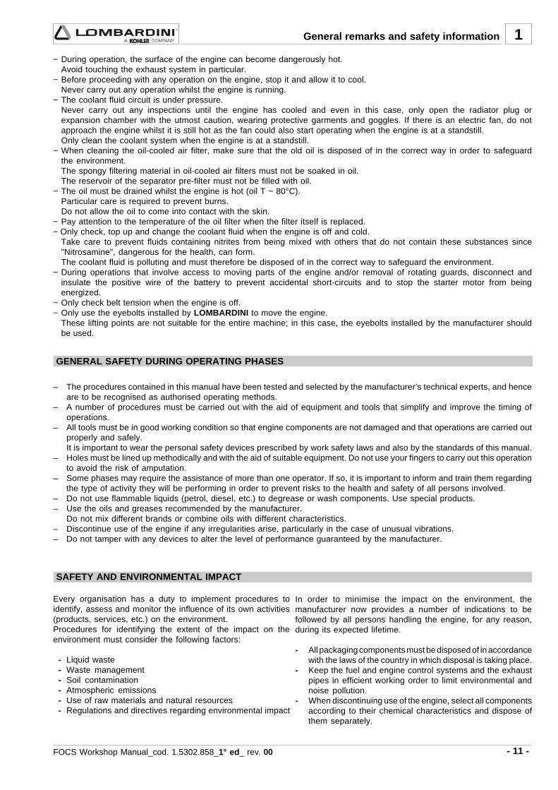
− During operation, the surface of the engine can become dangerously hot.Avoid touching the exhaust system in particular.
− Before proceeding with any operation on the engine, stop it and allow it to cool.Never carry out any operation whilst the engine is running.
− The coolant fluid circuit is under pressure.Never carry out any inspections until the engine has cooled and even in this case, only open the radiator plug orexpansion chamber with the utmost caution, wearing protective garments and goggles. If there is an electric fan, do notapproach the engine whilst it is still hot as the fan could also start operating when the engine is at a standstill.Only clean the coolant system when the engine is at a standstill.
− When cleaning the oil-cooled air filter, make sure that the old oil is disposed of in the correct way in order to safeguardthe environment.The spongy filtering material in oil-cooled air filters must not be soaked in oil.The reservoir of the separator pre-filter must not be filled with oil.
− The oil must be drained whilst the engine is hot (oil T ~ 80°C).Particular care is required to prevent burns.Do not allow the oil to come into contact with the skin.
− Pay attention to the temperature of the oil filter when the filter itself is replaced.− Only check, top up and change the coolant fluid when the engine is off and cold.
Take care to prevent fluids containing nitrites from being mixed with others that do not contain these substances since"Nitrosamine", dangerous for the health, can form.The coolant fluid is polluting and must therefore be disposed of in the correct way to safeguard the environment.
− During operations that involve access to moving parts of the engine and/or removal of rotating guards, disconnect andinsulate the positive wire of the battery to prevent accidental short-circuits and to stop the starter motor from beingenergized.
− Only check belt tension when the engine is off.− Only use the eyebolts installed by LOMBARDINI to move the engine.
These lifting points are not suitable for the entire machine; in this case, the eyebolts installed by the manufacturer shouldbe used.
General remarks and safety information
GENERAL SAFETY DURING OPERATING PHASES
– The procedures contained in this manual have been tested and selected by the manufacturer’s technical experts, and henceare to be recognised as authorised operating methods.
– A number of procedures must be carried out with the aid of equipment and tools that simplify and improve the timing ofoperations.
– All tools must be in good working condition so that engine components are not damaged and that operations are carried outproperly and safely.It is important to wear the personal safety devices prescribed by work safety laws and also by the standards of this manual.
– Holes must be lined up methodically and with the aid of suitable equipment. Do not use your fingers to carry out this operationto avoid the risk of amputation.
– Some phases may require the assistance of more than one operator. If so, it is important to inform and train them regardingthe type of activity they will be performing in order to prevent risks to the health and safety of all persons involved.
– Do not use flammable liquids (petrol, diesel, etc.) to degrease or wash components. Use special products.– Use the oils and greases recommended by the manufacturer.
Do not mix different brands or combine oils with different characteristics.– Discontinue use of the engine if any irregularities arise, particularly in the case of unusual vibrations.– Do not tamper with any devices to alter the level of performance guaranteed by the manufacturer.
SAFETY AND ENVIRONMENTAL IMPACT
Every organisation has a duty to implement procedures toidentify, assess and monitor the influence of its own activities(products, services, etc.) on the environment.Procedures for identifying the extent of the impact on theenvironment must consider the following factors:
- Liquid waste - Waste management - Soil contamination - Atmospheric emissions - Use of raw materials and natural resources - Regulations and directives regarding environmental impact
In order to minimise the impact on the environment, themanufacturer now provides a number of indications to befollowed by all persons handling the engine, for any reason,during its expected lifetime.
- All packaging components must be disposed of in accordancewith the laws of the country in which disposal is taking place.
- Keep the fuel and engine control systems and the exhaustpipes in efficient working order to limit environmental andnoise pollution.
- When discontinuing use of the engine, select all componentsaccording to their chemical characteristics and dispose ofthem separately.

- 12 - FOCS Workshop Manual_cod. 1.5302.858_1° ed_ rev. 00
2
POSSIBLE CAUSE
TROUBLE
FU
EL
CIR
CU
ITE
LE
CT
RIC
SY
ST
EM
MA
INT
EN
AN
CE
SE
TT
ING
S R
EP
AIR
S
TROUBLE SHOOTING
THE ENGINE MUST BE STOPPED IMMEDIATELY WHEN:1) - The engine rpms suddenly increase and decrease;2) - A sudden and unusual noise is heard;3) - The colour of the exhaust fumes suddenly darkens;4) - The oil pressure indicator light turns on while running.
TABLE OF LIKELY ANOMALIES AND THEIR SYMPTOMSThe following table contains the possible causes of some failures which may occur during operation.Always perform these simple checks before removing or replacing any part.
TECHNICAL INFORMATION
Clogged fuel pipes
Clogged fuel filter
Air or water in the fuel circuit
Tank cap breather blocked
Faulty fuel pump
Lack of fuel
Excessive valve clearancesAbsence of valve clearancesIncorrect speed governor leveragesSpeed governor spring broken or disengagedIdle lowWorn out or stuck ringsWorn out cylindersWorn out valve guidesBad valve sealBearing shells of bearing cap - piston rod -rocker worn outE.G.R. valve blocked openGovernor leverages not runningCylinder head gasket damagedFaulty timing systemSupplementary starter spring broken ordisengaged
Clogged air filter
Prolonged operation at idle
Incomplete run-in
Overloaded engine
Glow plug fuse burned
Faulty glow plug control relay
Flat batteryUnclear or mistaken cable connectionFaulty starter switchFaulty starting motorFaulty glow plugs
Eng
ine
over
heat
s
Oil
and
fuel
drip
ping
from
the
exha
ust
Exc
essi
ve o
ilco
nsum
ptio
n
Oil
leve
l inc
reas
e
Oil
prea
ssur
e to
o lo
w
Whi
te s
mok
e
Bla
ck s
mok
e
Non
-uni
form
spe
ed
No
acce
lera
tion
Eng
ine
star
ts b
ut s
tops
Eng
ine
does
not
sta
rt
Hig
h no
ise
leve
l
Inad
equa
tepe
rfor
man
ce

- 13 -FOCS Workshop Manual_cod. 1.5302.858_1° ed_ rev. 00
2
INJE
CT
ION
LU
BR
ICA
TIO
NC
IRC
UIT
CO
OL
ING
CIR
CU
IT
POSSIBLE CAUSE
TROUBLE
Technical information
High oil levelLow oil levelDirty or blocked pressure regulation valveWorn oil pumpAir to the oil suction hoseFaulty manometer or pressure switchOil in sump suction hose blockedOil in sump drainage pipe blockedFaulty spray nozzles (Turbo engines only)
Damaged injectorDamaged injection pump valveIncorrectly calibrated injectorWorn or damaged pumping elementIncorrect injection pump delivery setting(delivery equalisation)Hardened pump/injector control rodCracked or broken pre-combustionchamberIncorrect adjustment of the injectionsystems (delivery equalisation advance)Insufficient refrigerant fluid
Defective fan, radiator, or radiator cap
Defective thermostatic valve
Loss of refrigerant fluid from the radiator,hoses, engine crankshaft or water pump.Inside of radiator or coolant lines obstructed.
Defective or worn water pump
Alternator fan drive belt loose or torn
Heat exchange surface of the radiator clogged
Eng
ine
over
heat
s
Oil
and
fuel
drip
ping
from
the
exha
ust
Exc
essi
ve o
ilco
nsum
ptio
n
Oil
leve
l inc
reas
e
Oil
prea
ssur
e to
o lo
w
Whi
te s
mok
e
Bla
ck s
mok
e
Non
-uni
form
spe
ed
No
acce
lera
tion
Eng
ine
star
ts b
ut s
tops
Eng
ine
does
not
sta
rt
Hig
h no
ise
leve
l
Inad
equa
tepe
rfor
man
ce

- 14 - FOCS Workshop Manual_cod. 1.5302.858_1° ed_ rev. 00
2 Technical information
MANUFACTURER AND ENGINE IDENTIFICATION
Engine type
Engine serial number
Maximum operating speed
Number of the customer version(form K)
Manufacturer identification
Approval data

- 15 -FOCS Workshop Manual_cod. 1.5302.858_1° ed_ rev. 00
N°
mm
mm
Cm³
Nm
RPM
g/KWh
Kg/h
Kg
l./1'
m³/min
Kg.
αααααααααα
LDW
1003
3
75
77.6
1028
22,8:1
3600
19
58
@ 2200
300
0,013
87
1850
63
300
35°
25°
2Technical information
Cylinders
Bore
Stroke
Displacements
Compression rate
Rpm
Maximum power N 80/1269/CEE-ISO 1585-DIN 70020
Maximum torque
Specific fuel consumption**
Oil consumption **
Dry weight of engine
Combustion air volume at 3600 Rpm
Cooling air volume at 3600 Rpm
Axial load allowed on crankshaft (both directions)
Max tilt Instant operation (up to 1 min)
Intermittent operation (up to 30 min)
** At max. power
ENGINE TYPE

- 16 - FOCS Workshop Manual_cod. 1.5302.858_1° ed_ rev. 00
Nm
0
10
20
30
40
50
60
70
rpm
1200 1300 1400 1500 1600 1700 1800 1900 2000 2100 2200 2300 2400 2500 2600 2700 2800 2900 3000 3100 3200 3300 3400 3500 3600 3700
600
400
320
290
270
260
255250
250
245
304294
287
260256250256
244
2
LDW 1003
Technical information
N (80/1269/CEE - ISO 1585 - DIN 70020)AUTOMOTIVE RATING: intermittent operation with variable speed and variable load.
The above power values refer to an engine fitted with air cleaner and standard muffler, after testing and at theenvironmental conditions of 20°C and 1 bar. Max. power tolerance is 5%. Power decreases by approximately 1% every100 m di altitude and by 2% every 5°C above 25°C.
Note: Consult LOMBARDINI for power, torque curves and specific consumptions at rates differing from those given above.
ImportantNon-approval by Lombardini for any modifications releases the company from any damages incurred by theengine.
PERFORMANCE DIAGRAMS

- 17 -FOCS Workshop Manual_cod. 1.5302.858_1° ed_ rev. 00
2
A
B
C
J
K
L
M
216
176,3
88
86
30
S
T
U
V
30
266
383
63,5
58
12
157,4
135D
E
F
G
H
I
155,8
145,2
25
13
306,1
397,7
334,5
141,9
148,7
16
W
X
Y
Z
A1
N
O
P
Q
R
239,1
181,2
351,7
268,1
A N
CD
EFHIG
L
J
K
MB
O
P
Q
R
S
TU
V
W
X Y Z
A1
Technical information
DIMENSIONS (mm)
TECHNICAL SPECIFICATIONS

- 18 - FOCS Workshop Manual_cod. 1.5302.858_1° ed_ rev. 00
1
33
20 30 40 6050 80 90 130 140 150( x 1000 Km )
10 70 100 110 120
1 1,5 2 32,5 4 4,5 6,5 7 7,5(6) 3,5 5 5,5 6
ImportantNon compliance with the instructions provided in the chart entails risk of technical damages to the machine and/orthe system. Carry out maintenance regularly (after predefined number of km, or within the time intervals scheduled).Continue the periodical maintenance after 100,000 km by starting from 7,500 km.
ORDINARY MAINTENANCE
OPERATION
FREQUENCY x KM
CHECK
REPLACEMENT
MAINTENANCE - RECOMMENDED OIL TYPE - REFILLING
ROUTINE ENGINE MAINTENANCE
Radiator finsValve and rockerarms clearanceEngine oilSolenoid valveoperationFuel pipes andconnectionsCoolant
Alternator beltTiming beltAir filter elementEngine oilOil filterFuel filterCoolant
Alternator beltTiming beltFuel pipe
CLEANING
COMPONENT
EVERY 100.000 km (or when disassembling)
EVERY 4 years
EVERY 3.500 Km
EVERY 50.000 Km
EVERY 10.000 Km
EVERY 3.500 Km
EVERY 10.000 Km
EVERY 10.000 Km
EVERY 10.000 Km
- 19 -FOCS Workshop Manual_cod. 1.5302.858_1° ed_ rev. 00
3
123456789012345678901234567890SAE 20W*1234567890123456789123456789012345678912345678901234567891234567890123456789SAE 30*1234567890123456
12345678901234561234567890123456SAE 40*123456789012345678901234
123456789012345678901234123456789012345678901234SAE 10W-30**123456789012345678901234567891234567890123456789012345678912345678901234567890123456789SAE 10W-40**123456789012345678901234567890121123456789012345678901234567890121123456789012345678901234567890121SAE 10W-60**1234567890123456789012345
12345678901234567890123451234567890123456789012345
12345678901234567890123456712345678901234567890123456712345678901234567890123456712345678901234567890123456789
1234567890123456789012345678912345678901234567890123456789
SAE 15W-40 **
SAE 15W-40 **
SAE 20W-60 **
SAE 5W-30 ***
SAE 0W-30 ***
-30
-25
-20
-15
-10
-5 0
+5
+10
+15
+20
+25
+30
+35
+40
+45123456789012
123456789012123456789012SAE 10W*
+50
-35
-40
SAE 5W-40 ***
123456789012345123456789012345123456789012345123456789012345
12345678901123456789011234567890112345678901CF CE CD CC SC SD SE SF SG
L- 46152 D / E
SHAPI SJ SLCH-4 CG-4 CF-4
MIL
CF-2
123456789012345678123456789012345678123456789012345678
123456789011234567890112345678901
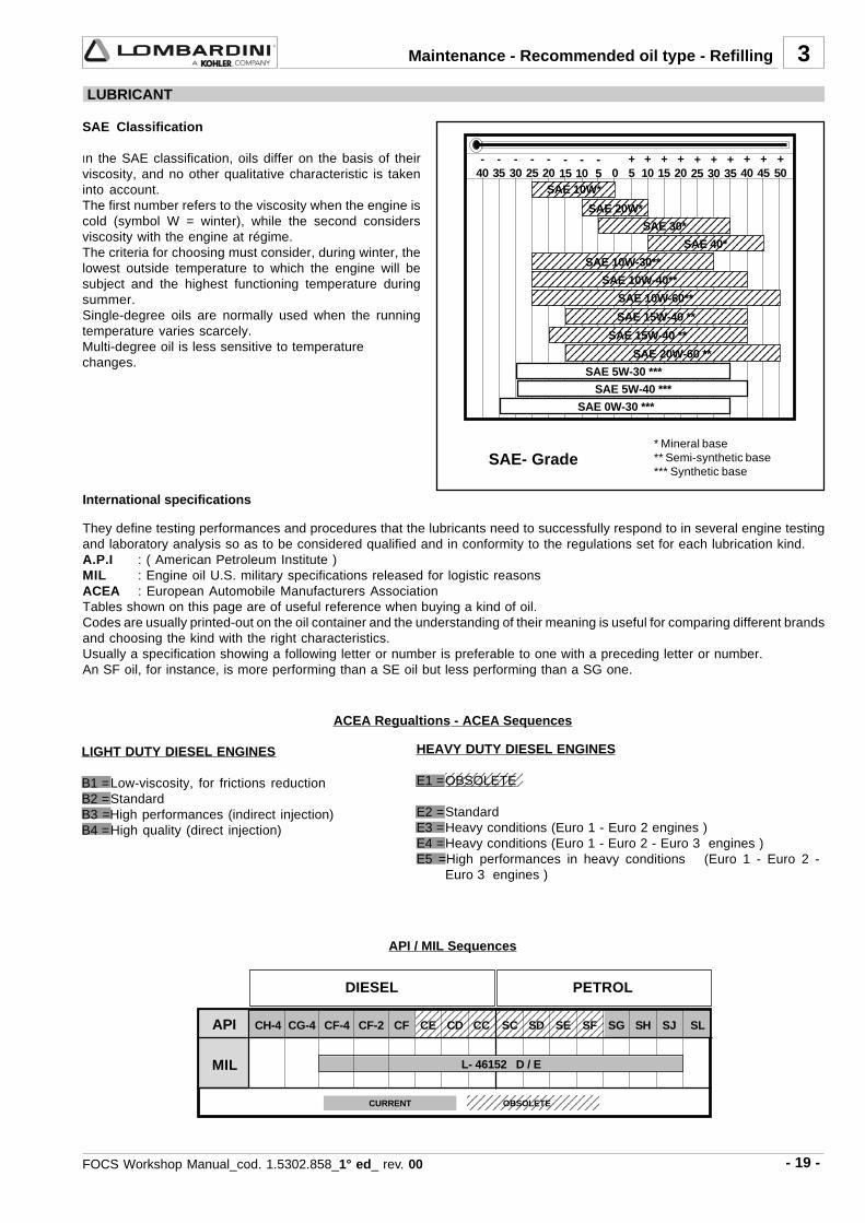
International specifications
They define testing performances and procedures that the lubricants need to successfully respond to in several engine testingand laboratory analysis so as to be considered qualified and in conformity to the regulations set for each lubrication kind.A.P.I : ( American Petroleum Institute )MIL : Engine oil U.S. military specifications released for logistic reasonsACEA : European Automobile Manufacturers AssociationTables shown on this page are of useful reference when buying a kind of oil.Codes are usually printed-out on the oil container and the understanding of their meaning is useful for comparing different brandsand choosing the kind with the right characteristics.Usually a specification showing a following letter or number is preferable to one with a preceding letter or number.An SF oil, for instance, is more performing than a SE oil but less performing than a SG one.
API / MIL Sequences
LIGHT DUTY DIESEL ENGINES
B1 =Low-viscosity, for frictions reductionB2 =StandardB3 =High performances (indirect injection)B4 =High quality (direct injection)
HEAVY DUTY DIESEL ENGINES
E1 =OBSOLETE
E2 =StandardE3 =Heavy conditions (Euro 1 - Euro 2 engines )E4 =Heavy conditions (Euro 1 - Euro 2 - Euro 3 engines )E5 =High performances in heavy conditions (Euro 1 - Euro 2 -
Euro 3 engines )
ACEA Regualtions - ACEA Sequences
OBSOLETE
DIESEL PETROL
CURRENT
LUBRICANT
SAE Classification
In the SAE classification, oils differ on the basis of theirviscosity, and no other qualitative characteristic is takeninto account.The first number refers to the viscosity when the engine iscold (symbol W = winter), while the second considersviscosity with the engine at régime.The criteria for choosing must consider, during winter, thelowest outside temperature to which the engine will besubject and the highest functioning temperature duringsummer.Single-degree oils are normally used when the runningtemperature varies scarcely.Multi-degree oil is less sensitive to temperaturechanges.
* Mineral base** Semi-synthetic base*** Synthetic base
SAE- Grade
Maintenance - Recommended oil type - Refilling

- 20 - FOCS Workshop Manual_cod. 1.5302.858_1° ed_ rev. 00
AGIP SINT 20005 W 40
API SJ / CF 4ACEA A3-96 B3-96MIL - L-46152 D/E
3
LDW 1003
4,1
3,1
4,0
3,0
max
min
max
min
specifications
PRESCRIBED LUBRICANT
In the countries where AGIP products are not available, use oil API CF/SH for Diesel engines or oil corresponding to themilitary specification MIL-L-2104 C/46152 D.
OIL CAPACITY
OIL VOLUME(OIL FILTER INCLUDED)
OIL VOLUME(WITHOUT OIL FILTER)
Litres
Litres
Danger – Attention- The engine may be damaged if operated with insufficient lube oil. It is also dangerous to supply too much lube oil
to the engine because a sudden increase in engine rpm could be caused by its combustion.
- Use proper lube oil preserve your engine. Good quality or poor quality of the lubricating oil has an affect on engineperformance and life.
- If inferior oil is used, or if your engine oil is not changed regularly, the risk of piston seizure, piston ring sticking,and accelerated wear of the cylinder liner, bearing and other moving components increases significantly.
- Always use oil with the right viscosity for the ambient temperature in which your engine is being operated.
Danger – Attention- The used engine oil can cause skin-cancer if kept frequently in contact for prolonged periods.
- If contact with oil cannot be avoided, wash carefully your hands with water and soap as soon as possible.
- Do not disperse the oil in the ambient, as it has a high pollution power.
Maintenance - Recommended oil type - Refilling

- 21 -FOCS Workshop Manual_cod. 1.5302.858_1° ed_ rev. 00
3
1,30
LDW 1003
API CF4 - CG4
API CF
Maintenance - Recommended oil type - Refilling
COOLANT
Danger – Attention- The fluid coolant circuit is pressurized. Inspections must only be made when the engine has cooled and even in
this case, the radiator or expansion chamber plug must be unscrewed with the utmost caution.- If an electric fan is installed, do not approach a hot engine since the fan itself could start up even when the
engine is at a standstill.- Coolant fluid is polluting, it must therefore be disposed of in the correct way. Do not litter.
The anti-freeze protection liquid (AGIP ANTIFREEZE SPEZIAL) must be used mixed with water, preferably decalcified. Thefreezing point of the cooling mixture depends on the product concentration in water, it is therefore recommended to use a 50%diluted mixture which guarantees a certain degree of optimal protection. As well as lowering the freezing point, the permanentliquid also raises the boiling point.
Coolant refueling
For information concerning the capacity of Lombardini radiators, please contact Lombardini directly.The total volume for refilling the cooling liquid varies according to the type of engine and radiator.
FUEL RECOMMENDATIONS
Purchase diesel fuel in small quantities and store in clean, approved containers. Clean fuel prevents the diesel fuel injectorsand pumps from clogging. Do not overfill the fuel tank.Leave room for the fuel to expand. Immediately clean up any spillage during refueling.
Never store diesel fuel in galvanized containers; diesel fuel and the galvanized coating react chemically to each other, producingflaking that quickly clogs filters or causes fuel pump or injector failure.
High sulfur content in fuel may cause engine wear. In those countries where diesel has a high sufur content, its is advisable tolubricate the engine with a high alkaline oil or alternatively to replace the lubricating oil recommended by the manufacturermore frequently. The regions in which diesel normally has a low sulfur content are Europe, North America, and Australia.
FUEL TYPEFor best results, use only clean, fresh, commercial-grade diesel fuel. Diesel fuels that satisfy the following specifications aresuitable for use in this engine: ASTM D-975 - 1D or 2D, EN590, or equivalent.
FUELS FOR LOW TEMPERATURES
It is possible to run the engine at temperatures below 0°C using special winter fuels. These fuels reduce the formation of paraffinin diesel at low temperatures. If paraffin forms in the diesel, the fuel filter becomes blocked interrupting the flow of fuel.
Fuel can be: - Summer up to 0°C- Winter up to -10°C- Alpine up to -20°C- Arctic up to -30°C
BIODIESEL FUELFuels containing less than 20% methyl ester or B20, are suitable for use in thisengine. Biodiesel fuels meeting the specification of BQ-9000 or equivalent arerecommended. DO NOT use vegetable oil as a biofuel for this engine.Any failures resulting from the use of fuels other than recommended will not bewarranted.
AVIATION FUELAviation fuels suitable for use in this engine include JP5, JP4, JP8 and, JET-A(if 5 percent oil is added).
Fuel with low sulphur content
Fuel with high sulphur content
EMISSION CONTROL INFORMATION
LOW SULFUR FUEL ORULTRA LOW SULFUR FUEL ONLY
EPA /CARB emission label must beattached near the fuel inlet.
PRESCRIBED LUBRICANT
ENGINE TYPE
CAPACITY (Litres) Without radiator
- 22 - FOCS Workshop Manual_cod. 1.5302.858_1° ed_ rev. 00
4
ImportantTo locate specific topics, the reader should refer to the index.
– Besides disassembly and reassembly operations this chapter also includes checking and setting specifications, dimensions,repair and operating instructions.
– Always use original LOMBARDINI spare parts for proper repair operations.
– The operator must wash, clean and dry components and assemblies before installing them.
– The operator must make sure that the contact surfaces are intact, lubricate the coupling parts and protect those that areprone to oxidation.
– Before any intervention, the operator should lay out all equipment and tools in such a way as to enable him to carry outoperations correctly and safely.
– For safety and convenience, you are advised to place the engine on a special rotating stand for engine overhauls.
– Before proceeding with operations, make sure that appropriate safety conditions are in place, in order to safeguard theoperator and any persons involved.
– In order to fix assemblies and/or components securely, the operator must tighten the fastening parts in a criss-cross oralternating pattern.
– Assemblies and/or components with a specific tightening torque must initially be fastened at a level lower than the assignedvalue, and then subsequently tightened to the final torque.
DISASSEMBLY / REASSEMBLY
RECOMMENDATIONS FOR OVERHAULS AND TUNING
ImportantTo locate specific topics, the reader should refer to the index.
– Before any intervention, the operator should lay out all equipment and tools in such a way as to enable him to carry outoperations correctly and safely.
– The operator must comply with the specific measures described in order to avoid errors that might cause damage to theengine.
– Before carrying out any operation, clean the assemblies and/or components thoroughly and eliminate any deposits orresidual material.
– Wash the components with special detergent and do not use steam or hot water.
– Do not use flammable products (petrol, diesel, etc.) to degrease or wash components. Use special products.
– Dry all washed surfaces and components thoroughly with a jet of air or special cloths before reassembling them.
– Apply a layer of lubricant over all surfaces to protect them against oxidation.
– Check all components for intactness, wear and tear, seizure, cracks and/or faults to be sure that the engine is in goodworking condition.
– Some mechanical parts must be replaced en bloc, together with their coupled parts (e.g. valve guide/valve etc.) as specifiedin the spare parts catalogue.
Danger - AttentionDuring repair operations, when using compressed air, wear eye protection.
RECOMMENDATIONS FOR DISASSEMBLING AND ASSEMBLING
- 23 -FOCS Workshop Manual_cod. 1.5302.858_1° ed_ rev. 00
4
2
1
1
1
2 2
22
108
4
6
5
1
1112
2
7
13
3 9810
Disassembly / Reassembly
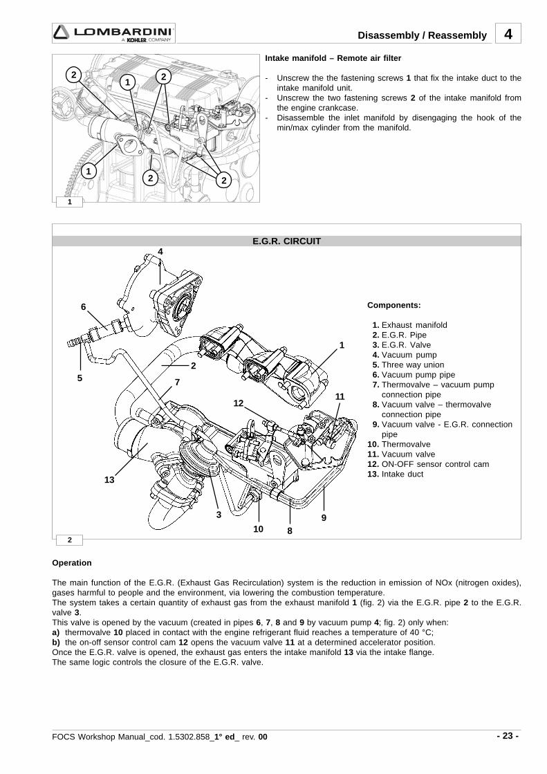
Components:
1. Exhaust manifold 2. E.G.R. Pipe 3. E.G.R. Valve 4. Vacuum pump 5. Three way union 6. Vacuum pump pipe 7. Thermovalve – vacuum pump
connection pipe 8. Vacuum valve – thermovalve
connection pipe 9. Vacuum valve - E.G.R. connection
pipe10. Thermovalve11. Vacuum valve12. ON-OFF sensor control cam13. Intake duct
Intake manifold – Remote air filter
- Unscrew the the fastening screws 1 that fix the intake duct to theintake manifold unit.
- Unscrew the two fastening screws 2 of the intake manifold fromthe engine crankcase.
- Disassemble the inlet manifold by disengaging the hook of themin/max cylinder from the manifold.
E.G.R. CIRCUIT
Operation
The main function of the E.G.R. (Exhaust Gas Recirculation) system is the reduction in emission of NOx (nitrogen oxides),gases harmful to people and the environment, via lowering the combustion temperature.The system takes a certain quantity of exhaust gas from the exhaust manifold 1 (fig. 2) via the E.G.R. pipe 2 to the E.G.R.valve 3.This valve is opened by the vacuum (created in pipes 6, 7, 8 and 9 by vacuum pump 4; fig. 2) only when:a) thermovalve 10 placed in contact with the engine refrigerant fluid reaches a temperature of 40 °C;b) the on-off sensor control cam 12 opens the vacuum valve 11 at a determined accelerator position.Once the E.G.R. valve is opened, the exhaust gas enters the intake manifold 13 via the intake flange.The same logic controls the closure of the E.G.R. valve.

- 24 - FOCS Workshop Manual_cod. 1.5302.858_1° ed_ rev. 00
3
6
4
5
7
6
4
4
4
5
6
5
E.G.R. CircuitDisassembly:
- Disengage the control rod catch 1 with a screwdriver from theaccelerator control rod 2 (fig. 3).
- Disconnect the accelerator control rod from the acceleratorcontrol lever 3 (fig. 3).
- Disconnect the thermovalve – vacuum pump connection pipes(7, fig. 2) and vacuum valve – thermovalve connection pipe (8,fig. 2) from the thermovalve (10, fig.2).
- Unscrew the two fastening screws 5 that fix the E.G.R. pipe 6 tothe E.G.R. valve 4 (fig. 4).
- Remove the intake manifold. See "Intake manifold – Remote airfilter" on page 23 (Figure 1).
- Unscrew the fastening screws of the E.G.R. pipe supportbracket 7 (fig. 5) from the engine crankcase and disengage theE.G.R. pipe from the exhaust manifold.
Reassembly:
When reassembling pay attention to the repositioning of thegaskets and to the precise connection of the pipes (6, 7, 8, 9, fig.2).These pipes should be carefully fitted on the appropriateconnections.
Tighten the screws to specified torque, see "Table of tighteningtorques for the main components" on page 80.
For the calibration of the E.G.R. system see "E.G.R. calibration"on page 77.
Disassembly / Reassembly

- 25 -FOCS Workshop Manual_cod. 1.5302.858_1° ed_ rev. 00
4
10a 10b
9
7
8
2
1
1
1
1 4 3 56
72
8
2
1
Disassembly / Reassembly
Alternator/Cooling fan belt drive
Danger - AttentionCheck the belt tension only with the engine off.
Tension adjustment.Loosen screws 1 and 2.Adjust the belt tension so that a 100N force at the midpoint of thebelt center (as shown) results in a 10-15mm deflection.
See page 18 for periodic maintenance details.
Vacuum pump and vacuum pump flange
Unscrew the three fastening screws 1 that fix the vacuum pump tothe flange and remove the vacuum pump.Unscrew the fastening screws that fix the flange to the enginecrankcase and remove it.
Components:
1. Vacuum pump2. Clic clamp 86-503. Vacuum pump flange4. Vacuum pump gasket-5. O-ring6. Three-way union for vacuum pump7. Vacuum pump pipe8. Screw
When reassembling, tighten the screws 8 that fix the flange to thecylinder head to the specified torque of 10 Nm.
Exhaust manifold - engines with EGR
Remove the E.G.R. pipe 1.Unscrew the locking nuts 2 and remove the exhaust manifold andthe seal.
Note: When reassembling the exhaust manifold, check that theinside is properly clean and free from cracks or breaks.
Note: Replace the gasket each time the manifold is reassembled.
Tighten the nuts at the prescribed torque of 25 Nm.

- 26 - FOCS Workshop Manual_cod. 1.5302.858_1° ed_ rev. 00
11
4
12
Flywheel
Danger - AttentionDuring dismounting be particularly careful not to let theflywheel fall, as this can be very dangerous for the operator.Use protective goggles while removing the starter ring gear.
Unscrew the screws that fasten it to the crankshaft.In order to replace the ring gear, it is necessary to disassemble theflywheel.Cut the ring gear in several places using a chisel and remove it.Heat the new ring gear uniformly and keep it at a temperature of300°C for 15÷20 minutes.Insert the ring gear into its seat and place it carefully on the rim of theflywheel.eave to the ring gear to cool gently before reassembling the flywheel.
When refitting tighten the screws at 80 Nm.
Driving pulley
ImportantTo loosen or screw in screw 1 at the set torque you mustalways stop the crankshaft and not other parts of the engine.
Lock the crankshaft.Remove the pulley, after having unscrewed central screw 1 andproceed with the four lateral screws.The central bolt 1 is left-handed.
When reassembling, apply some Moly-slip antiseizure compoundon the screw thread and tighten at 360 Nm.
Note: When pulley reference mark A aligns with the timing coverreference mark B, the flywheel side piston is at TDC.
Disassembly / Reassembly

- 27 -FOCS Workshop Manual_cod. 1.5302.858_1° ed_ rev. 00
4
13
14
15
17
16
18
Timing belt cover
Loosen the five screws and remove the cover.
When rifitting tighten the screws at a torque of 10 Nm.
Check the peripheral rubber sealing gasket and the two dust-protection rings of the two pulleys, if mounted.
Disassembly / Reassembly
Tightening pulley
Components:
1 Nut2 Washer3 Pulley4 Bearing5 Shaft/Support6 Mounting plate7 Tensioning lever
Timing belt removal
ImportantWhen you remove the distributor belt replace it even if itsprescribed operation time has not expired yet.
Danger – AttentionAlways check that the positive pole of the battery is insulated.
Remove the belt tensioner 1.Remove the timing belt off the timing pulley.
For assembly see fig. 22÷25.
Timing belt / Timing pulley arrangement
Components:
1 Camshaft pulley2 Timing belt3 Crankshaft pulley4 Coolant pump pulley5 Belt tensioner pulley
- 28 - FOCS Workshop Manual_cod. 1.5302.858_1° ed_ rev. 00
4
19
20
21
22 23
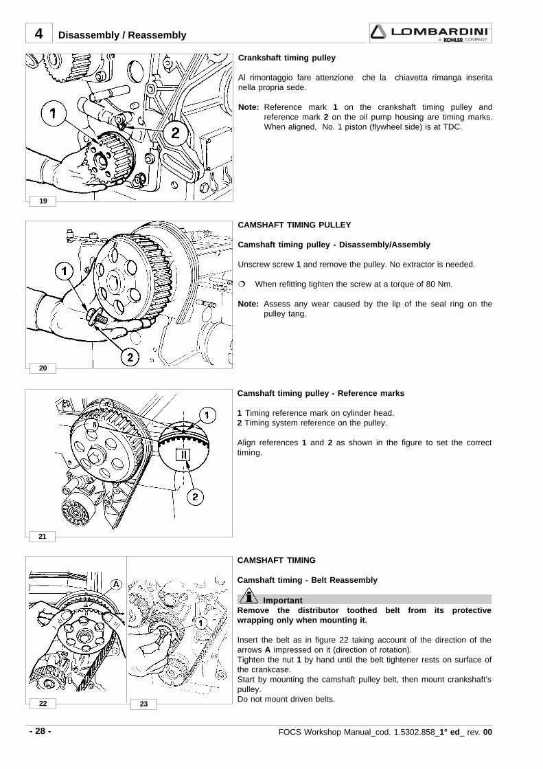
Crankshaft timing pulley
Al rimontaggio fare attenzione che la chiavetta rimanga inseritanella propria sede.
Note: Reference mark 1 on the crankshaft timing pulley andreference mark 2 on the oil pump housing are timing marks.When aligned, No. 1 piston (flywheel side) is at TDC.
Camshaft timing pulley - Reference marks
1 Timing reference mark on cylinder head.2 Timing system reference on the pulley.
Align references 1 and 2 as shown in the figure to set the correcttiming.
CAMSHAFT TIMING PULLEY
Camshaft timing pulley - Disassembly/Assembly
Unscrew screw 1 and remove the pulley. No extractor is needed.
When refitting tighten the screw at a torque of 80 Nm.
Note: Assess any wear caused by the lip of the seal ring on thepulley tang.
CAMSHAFT TIMING
Camshaft timing - Belt Reassembly
ImportantRemove the distributor toothed belt from its protectivewrapping only when mounting it.
Insert the belt as in figure 22 taking account of the direction of thearrows A impressed on it (direction of rotation).Tighten the nut 1 by hand until the belt tightener rests on surface ofthe crankcase.Start by mounting the camshaft pulley belt, then mount crankshaft’spulley.Do not mount driven belts.
Disassembly / Reassembly

- 29 -FOCS Workshop Manual_cod. 1.5302.858_1° ed_ rev. 00
4
25
26
24
Disassembly / Reassembly
Camshaft timing - Belt Tightening and Fastening
Insert the torque wrench in the suitable tool so that the A axis ofthe key fig. 25 is at 90° to the B axis of the tool in fig. 24.Tighten in clockwise direction at 20 Nm.
Maintaining the belt tension, tighten nut 3 with another torquewrench at 40 Nm, after having remounted the drive pulley.
Rotate the crankshaft a few times and check that the tension is asdescribed above.
The check must be carried out with the appropriate Nippon Densotension measuring instrument (halfway along the longest section ofthe belt), the value for a cold engine must be 15±2 Kg.
Valve timing check
A = Intake valveB = Exhaust valve
Rotate the engine in the normal direction of rotation until the No. 1piston (flywheel side) approaches TDC- compression strokeCheck the balance of intake and exhaust valves A and B placing thetwo micrometers testers on the valve collars.
Camshaft timing - Belt tightening tool
Position belt preload tool 7107-1460-049 1 over the timing belt idleradjustment ear 2.See "Camshaft timing - Belt Tightening and Fastening".
- 30 - FOCS Workshop Manual_cod. 1.5302.858_1° ed_ rev. 00
4
27
28
30
29
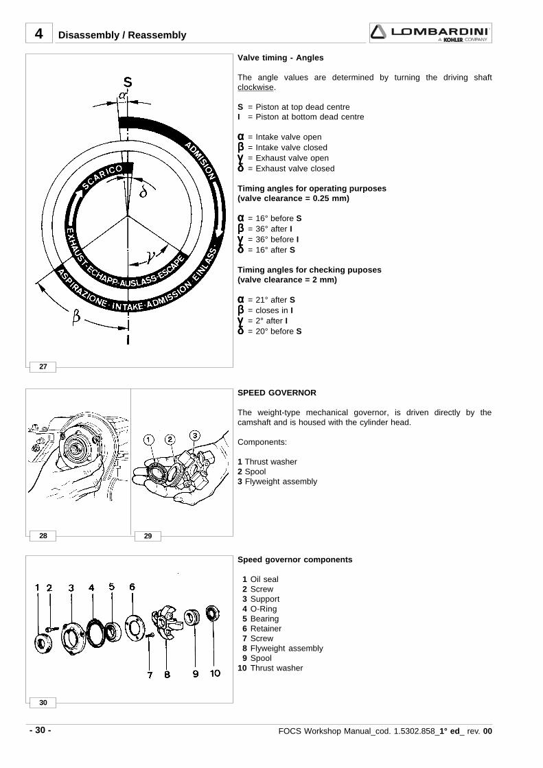
Valve timing - Angles
The angle values are determined by turning the driving shaftclockwise.
S = Piston at top dead centreI = Piston at bottom dead centre
ααααα = Intake valve openβββββ = Intake valve closedγγγγγ = Exhaust valve openδδδδδ = Exhaust valve closed
Timing angles for operating purposes(valve clearance = 0.25 mm)
ααααα = 16° before Sβββββ = 36° after Iγγγγγ = 36° before Iδδδδδ = 16° after S
Timing angles for checking puposes(valve clearance = 2 mm)
ααααα = 21° after Sβββββ = closes in Iγγγγγ = 2° after Iδδδδδ = 20° before S
Disassembly / Reassembly
SPEED GOVERNOR
The weight-type mechanical governor, is driven directly by thecamshaft and is housed with the cylinder head.
Components:
1 Thrust washer2 Spool3 Flyweight assembly
Speed governor components
1 Oil seal 2 Screw 3 Support 4 O-Ring 5 Bearing 6 Retainer 7 Screw 8 Flyweight assembly 9 Spool10 Thrust washer

- 31 -FOCS Workshop Manual_cod. 1.5302.858_1° ed_ rev. 00
4
31 32
33
34
Disassembly / Reassembly
Governor springs
Unscrew the pin that attaches it to the cylinder head.To remove it as shown in the figure it is necessary to dismount thecamshaft. It could also be removed from the accelerator box side byunscrewing the torque gearing device.Before reassembling it, check value A (45 to 46 mm) and theparallelism of the two levels B that must not exceed 0.05 mm.
Speed governor - Limiting speed governor
With applications for the automotive sector the regulator spring (C,fig. 31) is replaced by a device (plunger barrel) that only enables aconstant speed at the minimum and maximum rpm rating.
Components:
1 Nut2 Idle speed spring3 Max. speed spring4 Case5 Register6 Spring ring7 Actuation rod
Speed governor - Reassembly
Caution – WarningWhile reassembling, check the integrity of the componentsand check that they operate correctly.Bad operation of the speed governor can cause seriousdamage to the engine and to people being near to it.
Remount in reverse order to Fig. 30.When inserting the bearing in the camshaft, do it so that the fourblocks enter opened, so that they can receive the hose and closeover it.Check the integrity of the sealing rings of the cover.
Tighten the three screws at a torque of 10 Nm.
Note: With the speed governor mounted the camshaft axialclearance should be zero.

- 32 - FOCS Workshop Manual_cod. 1.5302.858_1° ed_ rev. 00
35
36
37 38
4
4
2
13
5
Oil pump - Reassembly
The pump rotors should be coupled on the same side, seereferences 2 and 3.Replace the O-ring 1.
Tighten the fastening screws to the crankcase at 25 Nm and thoseof the plate at 10 Nm.
See page 55 for technical details.
OIL PUMP
Oil pump - disassembly
The FOCS oil pump is supplied as an assembly. Lombardinitherefore recommends that the oil pump be handled as an assemblyfrom a service standpointLombardini does not recommend that the oil pump be disassembled,then reassembled for purposes of installation on the engine exceptduring emergency situations.
Rotate the crankshaft until the crankshaft timing pulley keyway isvertical as shown. Remove the oil pump assembly retaining bolts.When the crankshaft timing pulley keyway is vertical, the oil pumpdrive keyway A will be at 3:00 o’clock allowing removal of the oilpump assembly via relief B.
ROCKER ARM COVER
The engine control components are all on the cylinder head.The cover contains part of the lubrication duct of the camshaft andof the rocker arms, as well as part of the engine vent system.
Components:
1 Oil preassure switch2 Camshaft lubrification port3 Rocker arm lubrification port4 Oil exhaust hose from sump vent system5 Air valve with oil decanting wire gauze
Note: During remounting be careful with oil exhaust hose 4 thatneeds to be properly inserted into its housing on the cylinderhead.
Disassembly / Reassembly
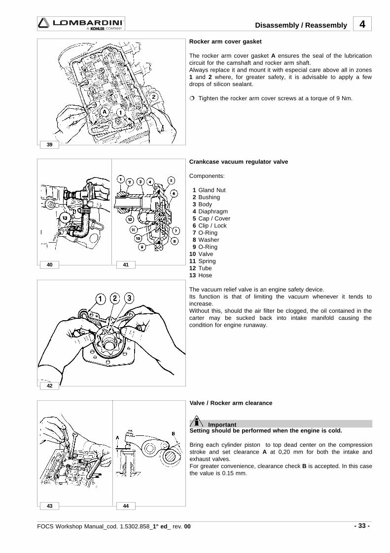
- 33 -FOCS Workshop Manual_cod. 1.5302.858_1° ed_ rev. 00
39
4
40 41
42
43 44
Rocker arm cover gasket
The rocker arm cover gasket A ensures the seal of the lubricationcircuit for the camshaft and rocker arm shaft.Always replace it and mount it with especial care above all in zones1 and 2 where, for greater safety, it is advisable to apply a fewdrops of silicon sealant.
Tighten the rocker arm cover screws at a torque of 9 Nm.
Crankcase vacuum regulator valve
Components:
1 Gland Nut 2 Bushing 3 Body 4 Diaphragm 5 Cap / Cover 6 Clip / Lock 7 O-Ring 8 Washer 9 O-Ring10 Valve11 Spring12 Tube13 Hose
The vacuum relief valve is an engine safety device.Its function is that of limiting the vacuum whenever it tends toincrease.Without this, should the air filter be clogged, the oil contained in thecarter may be sucked back into intake manifold causing thecondition for engine runaway.
Disassembly / Reassembly
Valve / Rocker arm clearance
ImportantSetting should be performed when the engine is cold.
Bring each cylinder piston to top dead center on the compressionstroke and set clearance A at 0,20 mm for both the intake andexhaust valves.For greater convenience, clearance check B is accepted. In this casethe value is 0.15 mm.

- 34 - FOCS Workshop Manual_cod. 1.5302.858_1° ed_ rev. 00
3001WDL
B D E
51,1÷5,0 5,6÷59,5 1,7÷0,7
45
47
48
46
49
4
Pump/injector unit - non-return valve
Non-return valve A immediately stops the engine whenever the stopis activated.
Dimensions (mm):
Note: If the value of B is not achieved, the two rings C are notsubject to enough compression to ensure the seal; any fuelloss would contaminate the lubrication oil and consequentlydamage the engine, F = metal gasket.
Fuel rail
When removing the fuel feeding pumps A, with the rail holders B,pay attention that the sealing O-rings C remain in their seats.
When refitting tighten the rail holder screws at a torque of 4 Nm.
Injection pump control rod
The injection pump control rod will link injectors to the enginegovernor.Screws 1 and 2 are pivoted on the delivery control lever of eachpump/injector B, unscrew the screws and remove spring 3.When refitting tighten the screws 1 and 2 at a torque of 1,1 Nmand make sure that they stop on lever B of each pump/injector andnot on rod A.
To carry out the delivery equalisation of the injection pumps seepage 67.To carry out the timing of the injection pumps and speedgovernor see page 74.
Disassembly / Reassembly

- 35 -FOCS Workshop Manual_cod. 1.5302.858_1° ed_ rev. 00
4
50
51
mm B-CB-C
A 00,1÷0
B 000,81÷989,71140,0÷510,0 090,0
C 030,81÷510,81
52 53
Pump/injector unit - Disassembly
When the removal (but not replacement) of a unit injector isrequired the following procedure may be used to avoid the need forother adjustments:Rotate the crankshaft until the unit injector cam lobe 2 forces thecam follower 1 to the highest position, then insert a suitable sized(hardened) pin into the hole 3 and rotate the crankshaft until thecam follower 1 is at the lowest position. In this way the injectionadvance regulator 4 remains calibrated.
Note: If you dismount more than one pump/injector unit, makesure to reinstall them in the appropriate housing (withrelative drive rod 5); before mounting lubricate the drive rodat its two ends with MOLYSLIP, AS COMPOUND 40 type.
Rocker arm assembly
Remove the nuts attaching the rocker arm assembly to the cylinderhead.
When refitting tighten the nuts at a torque of 40 Nm.
The pin, that is hollow inside to allow lubrication, is closed at itsends by two caps.
Note: The rocker arm assembly may be removed without removalof the unit injectors.
Disassembly / Reassembly
limit value
Rocker arm pivot, dismounting and remounting
To remove pivot 1 from the support 2 it's necessary to drill out pin 3using a 4mm drill bit.On remounting insert a new pin and reinsert it in bearing surface A(0 to 1 mm).Check the rod’s state of wear and tear (diam. B) and that of therocker arm holes (diam. C).Remove the closing caps 4 at the end and carefully clean inside.
Dimensions (mm):

- 36 - FOCS Workshop Manual_cod. 1.5302.858_1° ed_ rev. 00
A B B-AB-A
060,73÷530,73 000,73÷579,63 580,0÷530,0 071,0
54
56
58
59
55
57
4
CAMSHAFT
Camshaft, disassembly
Loosen the screws and remove the cover 1.Check gasket ring 2 for integrity.Remove the drive rod from the fuel pump.Gently remove the camshaft, slight rotations may be required toavoid binding the camshaft lobes against the camshaft bearingsurface bores.
Note: The lift pump drive eccentric 3 is included on the flywheel endof the camshaft and fixed with a screw.
In case of replacement tighten the eccentric screw at a torque of 80Nm.
Camshaft, journal and housing measurement
Use an inside micrometer gauge for housing diameters and an outsidemicrometer gauge for journal diameters.
Camshaft journals and housings - Dimensions (mm)
limit value
Camshaft lobe measurement
Use an outside micrometer gauge.
Disassembly / Reassembly
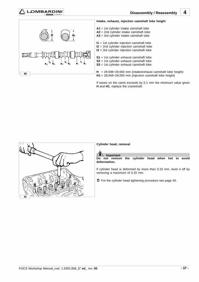
- 37 -FOCS Workshop Manual_cod. 1.5302.858_1° ed_ rev. 00
4
60
61
Intake, exhaust, injection camshaft lobe height
A1 = 1st cylinder intake camshaft lobeA2 = 2nd cylinder intake camshaft lobeA3 = 3rd cylinder intake camshaft lobe
I1 = 1st cylinder injection camshaft lobeI2 = 2nd cylinder injection camshaft lobeI3 = 3rd cylinder injection camshaft lobe
S1 = 1st cylinder exhaust camshaft lobeS2 = 1st cylinder exhaust camshaft lobeS3 = 1st cylinder exhaust camshaft lobe
H = 29,598÷29,650 mm (intake/exhaust camshaft lobe height)H1 = 28,948÷29,000 mm (injection camshaft lobe height)
If wears on the cams exceeds by 0.1 mm the minimum value givenH and H1, replace the crankshaft.
Disassembly / Reassembly
Cylinder head, removal
ImportantDo not remove the cylinder head when hot to avoiddeformation.
lf cylinder head is deformed by more than 0.10 mm, level it off byremoving a maximum of 0.20 mm.
For the cylinder head tightening procedure see page 45.

- 38 - FOCS Workshop Manual_cod. 1.5302.858_1° ed_ rev. 00
62
64
63
65
4
66
VALVES
To remove the valves it is necessary to remove the collets; place aspacer under the valve head, press strongly on the spring cap asshown in the picture.
Components: 1 Valve stem2 Valve stem seal ring3 Spring seat4 Spring5 Spring cap6 Collets
Valve stem sealing rings - Reassembly
To prevent deformation of the sealing ring 1 as it is inserted onto thevalve guide, insert it onto tool "7107-1460-047" 2 (after lubricatingthe sealing ring) and proceed as shown int the picture ensuring thatgasket 1 is completely fitted.
Valve springs
Measure free height with a gauge.
Free height A = 46 mm.
Note: If the free height A is less than 43,5 mm replace the spring.
Disassembly / Reassembly

- 39 -FOCS Workshop Manual_cod. 1.5302.858_1° ed_ rev. 00
4
67
ααααα1 = 60° 30' ÷ 60° 45'
A B C D E
6,63÷4,63 450,11÷540,11 810,11÷000,11 02,6÷08,5 58,9÷57,9
A B C
0,04÷5,93 020,7÷500,7 099,6÷069,6
68
69
C 34,40
ααααα = 45° 30' ÷ 45° 45'D 30,20
Valve, specifications
Exhaust valve AShaft and head are made of 2 different materials.
2 Welded joint3 Chromium-plated joint4 Portion made of: ........ X 45 Cr Si 8 UNI 39925 Portion made of: ........ X 70 Cr Mn NI N 216 UNI 3992
Intake valve BMaterial: X 45 Cr Si 8 UNI 3992
1 = Chromium-plated joint
Valve guides and valve guide housings
Both intake and exhasut valve guides are identical dimensionally andare made from phosphoric gray iron with a pearlitic matrix:
Dimensions (mm):
Note: Valve guides are supplied in finished form, further machiningis prohibited.Valve guides with outside diameter B increased by 0.5 mm.are available.
Valve guide insertion
Fit the guides with a punch taking account of value A in relation tothe cylinder head surface.
Dimensions (mm):
Clearance (mm):
(B-C) = 0,015÷0,050 (B- C) limite usura = 0,10
Disassembly / Reassembly

- 40 - FOCS Workshop Manual_cod. 1.5302.858_1° ed_ rev. 00
4
70
mm
A 542,53÷022,53
°54÷'35°44 °06÷'35°95B 513,53÷603,53
C 142,13÷022,13
D 613,13÷803,13
ααααα ααααα1
71
73
72
74 75
mm
D 0,1÷7,0 3,1
S 6,1 0,2
Valve seats and housings -
Dimensions (mm)
Press valve seats into the housings
Note: Valve seatsare supplied in finished form, further machining isprohibited.
Valve recess and seat sealing width
Dimensions (mm):
Grind valve seats with fine emery paste.After grinding check the valve recess D relative to the cylinder headsurface and the seat sealing width S.
PRE-COMBUSTION CHAMBER
Components:
1 Pre-combustion chamber2 Pre-heating glow plug3 Pre-combustion chamber ring nut4 Cylinder head
The pre-combustion chamber does not normally require removal orservice, if service is necessary follow the procedure described below.
Pre-combustion chamber ring nut removal
The pre-combustion chamber is fixed to the cylinder head by a ringnut, so before removing the pre-combustion chamber it is necessaryto unscrew the pre-combustion chamber ring nut.Use the special tool "7107-1460-027" 1 to romve the ring nut 2.
Disassembly / Reassembly
Limit value
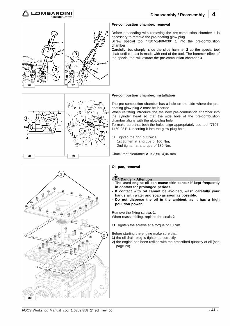
- 41 -FOCS Workshop Manual_cod. 1.5302.858_1° ed_ rev. 00
4
76
78
77
79
80
1
2
Pre-combustion chamber, removal
Before proceeding with removing the pre-combustion chamber it isnecessary to remove the pre-heating glow plug.Screw special tool "7107-1460-030" 1 into the pre-combustionchamber.Carefully, but sharply, slide the slide hammer 2 up the special toolshaft until contact is made with end of the tool. The hammer effect ofthe special tool will extract the pre-combustion chamber 3.
Pre-combustion chamber, installation
The pre-combustion chamber has a hole on the side where the pre-heating glow plug 2 must be inserted.When re-fitting introduce the the new pre-combustion chamber intothe cylinder head so that the side hole of the pre-combustionchamber aligns with the glow-plug hole.To make sure that both the holes align appropriately use tool "7107-1460-031" 1 inserting it into the glow-plug hole.
Tighten the ring nut twice:1st tighten at a torque of 100 Nm,2nd tighten at a torque of 180 Nm.
Chack that clearance A is 3,56÷4,04 mm.
Disassembly / Reassembly
Oil pan, removal
Danger - Attention- The used engine oil can cause skin-cancer if kept frequently
in contact for prolonged periods.- If contact with oil cannot be avoided, wash carefully your
hands with water and soap as soon as possible.- Do not disperse the oil in the ambient, as it has a high
pollution power.
Remove the fixing screws 1.When reassembling, replace the seals 2.
Tighten the screws at a torque of 10 Nm.
Before starting the engine make sure that:1) the oil drain plug is tightened correctly2) the engine has been refilled with the prescribed quantity of oil (see
page 20).

- 42 - FOCS Workshop Manual_cod. 1.5302.858_1° ed_ rev. 00
4
81
83
85
82
84
A 000,57÷099,47 049,47÷039,47
070,0÷050,0B 010,57÷000,57 059,47÷049,47
C 020,57÷010,57 069,47÷059,47
PISTON
Remove the connecting rod big end cap.Remove the piston-connecting rod assembly.
Note: The combustion chamber is a Ricardo type.
Piston, disassembly and inspection
Remove the stop rings and remove the pin (see fig. 83).Remove the piston rings and clean the slot.Measure diameter Q at height A from the base of skirt (A = 9 mm).If the diameter is worn more than the 0.05 mm minimum givenvalue, replace piston and rings.
Note: The provided oversize elements are of 0.50 mm and 1.00 mm
Stop pin rings, dismounting and remounting
Extract the ring inserting a pointed tool in hollow A.
On remounting, insert rings with the points turned downwards insidethe corners ( ααααα = 15°).
Piston, class
The pistons are subdivided according to their diameters into categories: A, B, C. These references, are shown on the top ofthe piston (see fig. 82).
Piston supply:
Pistons at the nominal diameter are only supplied in category A.Pistons oversized by 0.50 and 1.00 mm are supplied with reference to the increased level on the piston crown: Ø 75.5 – 76.0 .
Class Ø Cylinder - mm Ø Piston - mm Clearance - mm
Disassembly / Reassembly

- 43 -FOCS Workshop Manual_cod. 1.5302.858_1° ed_ rev. 00
4
86
A
°1 54,0÷52,0
0.1°2 54.0÷52,0
°3 54,0÷02,0
87
88
A 521,0÷090,0
B 580,0÷050.0
C 570,0÷040,0
90
89
Disassembly / Reassembly
Piston, weight
Weigh pistons when replacing them in order to avoid unbalance.The difference in weight should not exceed 4 g.
limit valuePiston ring
Piston rings - End gaps (mm)
Place piston rings squarely into the unworn part of the lower cylinderand measure the end gap A.
Piston ring, Clearance between grooves (mm)
Piston ring, mounting order
A = 1° ring (internal tapered and torsional)B = 2° ring (internal tapered and torsional)C = 3° Oil control ringD = Chrome-plated areaE = Chrome-plated area
Note: When there is writing on the surface of a piston ring, mountthat surface with face upward.
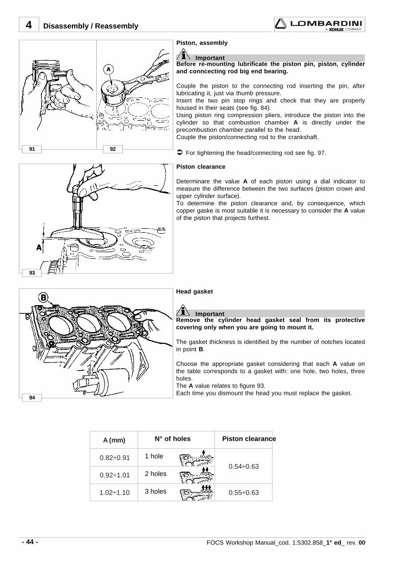
- 44 - FOCS Workshop Manual_cod. 1.5302.858_1° ed_ rev. 00
4
91
93
92
94
)mm(A
19.0÷28.036.0÷45.0
10.1÷29.0
01.1÷20.1 36.0÷55.0
Piston clearance
Determinare the value A of each piston using a dial indicator tomeasure the difference between the two surfaces (piston crown andupper cylinder surface).To determine the piston clearance and, by consequence, whichcopper gaske is most suitable it is necessary to consider the A valueof the piston that projects furthest.
Piston, assembly
ImportantBefore re-mounting lubrificate the piston pin, piston, cylinderand conncecting rod big end bearing.
Couple the piston to the connecting rod inserting the pin, afterlubricating it, just via thumb pressure.Insert the two pin stop rings and check that they are properlyhoused in their seats (see fig. 84).Using piston ring compression pliers, introduce the piston into thecylinder so that combustion chamber A is directly under theprecombustion chamber parallel to the head.Couple the piston/connecting rod to the crankshaft.
For tightening the head/connecting rod see fig. 97.
Disassembly / Reassembly
Head gasket
ImportantRemove the cylinder head gasket seal from its protectivecovering only when you are going to mount it.
The gasket thickness is identified by the number of notches locatedin point B.
Choose the appropriate gasket considering that each A value onthe table corresponds to a gasket with: one hole, two holes, threeholes.The A value relates to figure 93.Each time you dismount the head you must replace the gasket.
N° of holes Piston clearance
1 hole
2 holes
3 holes
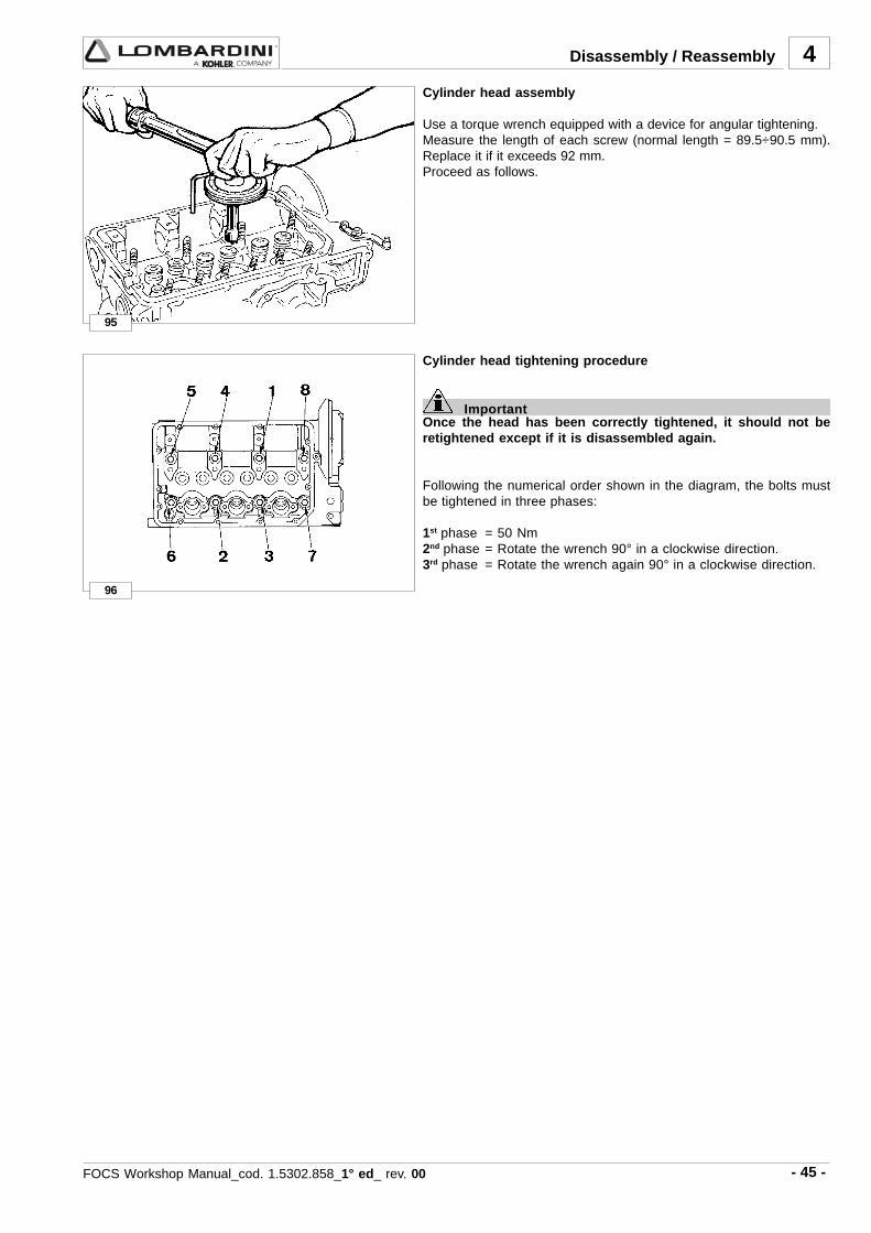
- 45 -FOCS Workshop Manual_cod. 1.5302.858_1° ed_ rev. 00
4
95
96
Disassembly / Reassembly
Cylinder head assembly
Use a torque wrench equipped with a device for angular tightening.Measure the length of each screw (normal length = 89.5÷90.5 mm).Replace it if it exceeds 92 mm.Proceed as follows.
Cylinder head tightening procedure
ImportantOnce the head has been correctly tightened, it should not beretightened except if it is disassembled again.
Following the numerical order shown in the diagram, the bolts mustbe tightened in three phases:
1st phase = 50 Nm2nd phase = Rotate the wrench 90° in a clockwise direction.3rd phase = Rotate the wrench again 90° in a clockwise direction.

- 46 - FOCS Workshop Manual_cod. 1.5302.858_1° ed_ rev. 00
4
98
100
99
97
Disassembly / Reassembly
Connecting rod with bearings and pin
Dimensions (mm):
B = 20,015÷20,025C = 40,021÷40,050 ..... (bearing tightened at 40 Nm)D = 19,996÷20,000E = 54,000÷55,100(B-D) = 0,015÷0,039 (B-D) limit value = 0,060
Note: When driving the small end bearing make sure both oilholesare aligned.
Connecting rod, weight
Weigh connecting rods when replacing them in order to avoidunbalance.The difference in weight should not exceed 10 g.The difference in weight of the pre-assembled connecting rod, pistonand pin must not exceed 14 g.
CONNECTING ROD
Caution – WarningWhile reassembling the big end bearings, we suggest cleaningall parts thoroughly, as well as proper greasing in order toavoid risks of seizure at the first start.
Big end bearing
After connecting rod from crankshaft disconnection, check thefollowing.While reassembling, be sure the two centring notches A an B areon the same side.
Tighten the connecting rod big end cap screws simultaneously ata torque of 40 Nm.
Note: The big end bearing is supplied both at the nominal valueand undersized by 0.25 and 0.50 mm.

- 47 -FOCS Workshop Manual_cod. 1.5302.858_1° ed_ rev. 00
4
101 102
103
105
104
106
Disassembly / Reassembly
CYLINDERS
Reset the dial gauge with a calibrated ring: check the diameter D inpoints 1, 2 and 3; repeat the same operation rotating the dial gaugeby 90° at the same heights.Check any wear in zone X where the piston rings operate and if it isgreater than the 0.05 mm max limit given adjust the cylinder to thenext increased value.
75.000 mm max limit.
Cylinder, class
The pistons (A, B, C) locations are shown on the piston crownwhile those for the cylinders are found on the crankcase in thepoints shown by the arrows, see picture.
Note: The cylinders are not to be changed.
Cylinder roughness
Caution – WarningDo not treat the cylinder’s internal surfaces with an emerycloth.
The angle of the crossed processing marks must be between 45°and 55°. These must be uniform and distinct in both directions.Average roughness must be between 0.5 and 1 µm.The whole surface of the cylinder affected by contact with the pistonrings must be rendered with the plateau method.
Connecting rod alignment
Using a gauge on a comparison plan, check the axial alignment byplacing the connecting rod on a V-blocks as shown.Maximum Axial Mis-alignment = 0,015mm, Limit =0,030mm.Minor mis-alignment may be corrected by skillfully and graduallyworking the connecting rod between centers on a press.

- 48 - FOCS Workshop Manual_cod. 1.5302.858_1° ed_ rev. 00
4
107
108 109
110 111
Disassembly / Reassembly
Rear and forward main bearing caps
ImportantBefore the final tightening and after it, using a ground bar,check the coplanarity of the horizontal and vertical levels.
On remounting the rear main bearing cap 1 replace the lateralrubber gaskets 2, keeping in mind that projections A and B of thesupport must be 0,5÷1,0 mm; cut off any exceeding portions.Do the same with the front bearing cap.Before reintroducing the bearings in the crankcase, place betweentheir surfaces two plates C and D - 0.1 mm thick - se.no.7107-1460-053.
Tighten the screws at a torque of 60 Nm.
Note: It is advisable to apply a few drops of silicon sealant on thesurface of the gasket slot 2.
Central main bearing caps
The central support caps are marked with locations that can benumbers as in the diagram or dots.The same locations are given on the crankcase.Couple the caps with the same references and on the same side. Inany case locate the bearing’s two centring notches that are to befound on the same side.
Tighten the screws simultaneously at a torque of 60 Nm.
Check the clearances between the bearings and the journal
Use the ”Perfect Circle Plastigage” type calibrated wire A and put itat the centre of the bearing with a bit of grease.
Tighten the screws at a torque of 60 Nm.
Find out the clearance value checking the wire’s compression withthe appropriate graduated scale supplied in the same pack andavailable on the market.
For clearance values between the journals, connecting rod pinand the relevant bearings see page 51.

- 49 -FOCS Workshop Manual_cod. 1.5302.858_1° ed_ rev. 00
4
112
113 114
A mm 313,0÷031,0 5,0
B mm 01,32÷50,32 05,32
C **B *A
dtS 029,22÷787,22 001,32÷050,32
313,0÷031,01a 021,32÷789,22 003,32÷052,32
2a 022,32÷780,3 004,32÷053,32
3a 023,32÷781,32 005,32÷054,32
115 116
Disassembly / Reassembly
Shoulder half rings
So as to keep them in their seats during assembly, put a bit ofgrease.The half-rings must be assembled with the slots A as in the figure.Thickness of half-rings is equal to 2.31÷2.36 mm.They are supplied as spare parts as increased thickness 0.1 and 0.2mm, see below.
Crankshaft axial clearance
After tightening the main bearings measure the axial clearance Abetween the crankshaft flywheel side shoulder and the main bearinghalf rings.
If the clearance is not within the given value check value B.If need be, fit oversized half rings, see below.
Limit valueRef. Clearance
Shoulder half rings, oversized elements
Dimensions (mm):
* A of Fig. 113.** B of Fig. 114.
Grinding B as per relevant table, you can mount the following halfrings:
1st Oversized element Half rings 1 and 2 + 0.10 mm on both sidesof the bearing
2nd Oversized element Half rings 1 and 2 + 0.10 mm on one side ofthe support and + 0.20 mm on the otherside.
3rd Oversized element Half rings 1 and 2 + 0.20 mm on both sidesof the bearing.

- 50 - FOCS Workshop Manual_cod. 1.5302.858_1° ed_ rev. 00
117
118
119 120
4
Crankshaft front and back oil seal rings
The front oil seal ring 1 inserted into the oil pump cover and the backone 2, in the flywheel side flange.If warped, hardened, or cracked, replace them.
For the replacement:- Carefully clean the housing- Keep the ring immersed in engine oil for about half an hour.- Drive it into its housing with a buffer exercising a uniform pressure
on the whole front surface. Be sure that the two surfaces A and Bmeet on the same level.
- Refill the interior hollow with grease and lubricate the seal lip withthickened oil.
Note: Before major engine overhaul, in case of oil leakage in theseal area of rings 3 and 4, you can remedy this by replacingthe rings and pushing them about 2 mm deeper with respectto the previous ones.If the rings are black it means zones 3 and 4 of the crankshaftare tempered. In this case it is necessary to remount a ring ofthe same colour.If the rings are brown it means that zones 3 and 4 of thecrankshaft are not tempered. In this case it is necessary toremount brown coloured rings.
Crankshaft, lubrication lines
Caution – WarningDuring repairs, when compressed air is used it is important towear protective goggles.
Put the crankshaft in a bath of crude oil.Use compressed air to clean the inside of the lines.Reposition the new caps in their seating and check the seal.
Crankshaft, check journals and crank
Use a micrometer for the outsides.
Disassembly / Reassembly
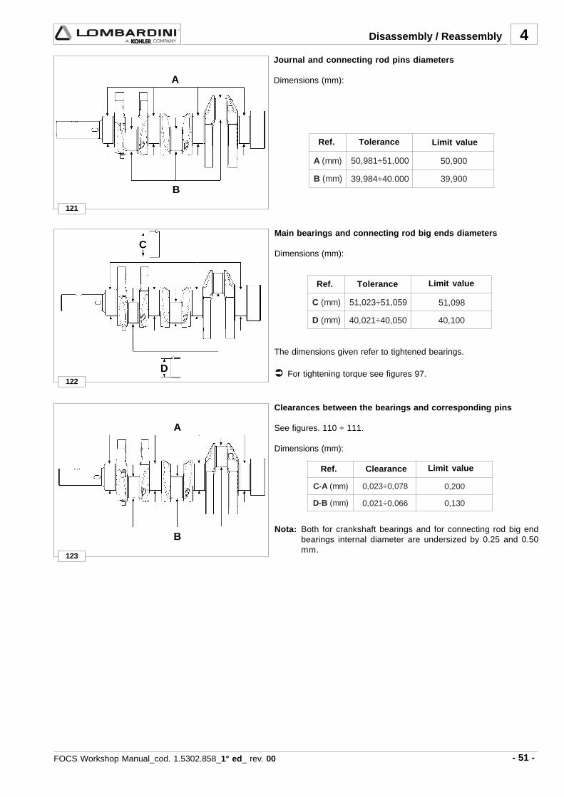
- 51 -FOCS Workshop Manual_cod. 1.5302.858_1° ed_ rev. 00
4
121
A )mm( 000,15÷189,05 009,05
B )mm( 000.04÷489,93 009,93
A
B
122
123
C )mm( 950,15÷320,15 890,15
D )mm( 050,04÷120,04 001,04
A-C )mm( 870,0÷320,0 002,0
B-D )mm( 660,0÷120,0 031,0
A
B
C
D
Journal and connecting rod pins diameters
Dimensions (mm):
Disassembly / Reassembly
Ref. Tolerance Limit value
Clearances between the bearings and corresponding pins
See figures. 110 ÷ 111.
Dimensions (mm):
Nota: Both for crankshaft bearings and for connecting rod big endbearings internal diameter are undersized by 0.25 and 0.50mm.
Main bearings and connecting rod big ends diameters
Dimensions (mm):
The dimensions given refer to tightened bearings.
For tightening torque see figures 97.
Ref. Tolerance
Ref. Clearance Limit value
Limit value

- 52 - FOCS Workshop Manual_cod. 1.5302.858_1° ed_ rev. 00
4
. .....................................................................................................................................................
. .....................................................................................................................................................
. .....................................................................................................................................................
. .....................................................................................................................................................
. .....................................................................................................................................................
. .....................................................................................................................................................
. .....................................................................................................................................................
. .....................................................................................................................................................
. .....................................................................................................................................................
. .....................................................................................................................................................
. .....................................................................................................................................................
. .....................................................................................................................................................
. .....................................................................................................................................................
. .....................................................................................................................................................
. ....................................................................................................................................................
. .....................................................................................................................................................
. .....................................................................................................................................................
. .....................................................................................................................................................
. .....................................................................................................................................................
. .....................................................................................................................................................
. .....................................................................................................................................................
. .....................................................................................................................................................
. .....................................................................................................................................................
. .....................................................................................................................................................
. .....................................................................................................................................................
. .....................................................................................................................................................
. .....................................................................................................................................................
. .....................................................................................................................................................
. .....................................................................................................................................................
Disassembly / Reassembly

- 53 -FOCS Workshop Manual_cod. 1.5302.858_1° ed_ rev. 00
4
. .....................................................................................................................................................
. .....................................................................................................................................................
. .....................................................................................................................................................
. .....................................................................................................................................................
. .....................................................................................................................................................
. .....................................................................................................................................................
. .....................................................................................................................................................
. .....................................................................................................................................................
. .....................................................................................................................................................
. .....................................................................................................................................................
. .....................................................................................................................................................
. .....................................................................................................................................................
. .....................................................................................................................................................
. .....................................................................................................................................................
. ....................................................................................................................................................
. .....................................................................................................................................................
. .....................................................................................................................................................
. .....................................................................................................................................................
. .....................................................................................................................................................
. .....................................................................................................................................................
. .....................................................................................................................................................
. .....................................................................................................................................................
. .....................................................................................................................................................
. .....................................................................................................................................................
. .....................................................................................................................................................
. .....................................................................................................................................................
. .....................................................................................................................................................
. .....................................................................................................................................................
. .....................................................................................................................................................
Disassembly / Reassembly

- 54 - FOCS Workshop Manual_cod. 1.5302.858_1° ed_ rev. 00
124
5
- The oil viscosity must suit the ambient temperature inwhich the engine operates.
Danger – Attention- Old engine oil can cause skin cancer if repeatedly left in
contact with the skin and for long periods of time.Wear protective gloves to avoid touching used oil.
- If contact with the oil is unavoidable, you are advised towash your hands with soap and water as soon as possible.Dispose of old oil in the correct way as it is highly polluting.
Danger – Attention- The engine can be damaged if allowed to operate with
insufficient oil. It is also dangerous to add too muchoil because its combustion may lead to a sharpincrease in the rotation speed.
- Use suitable oil in order to protect the engine.Nothing more than lubrication oil can influence theperformances and life of an engine.
- Use of an inferior quality oil or failure to regularlychange the oil will increase the risk of piston seizure,will cause the piston rings to jam and will lead to rapidwear on the cylinder liner, the bearings and all othermoving parts. Engine life will also be notably reduced.
LUBRIFICATION CIRCUIT
Components:
1 Pressure gauge 9 Oil filler cap2 Rocker shaft 10 Camshaft3 Connecting rod pin 11 Oil pressure regulating valve4 Oil filter cartridge 12 Oil pump5 Journal 13 Crankshaft6 Oil drain plug 14 Oil suction filter7 Oil dipstick8 Bleed
LUBRIFICATION CIRCUIT
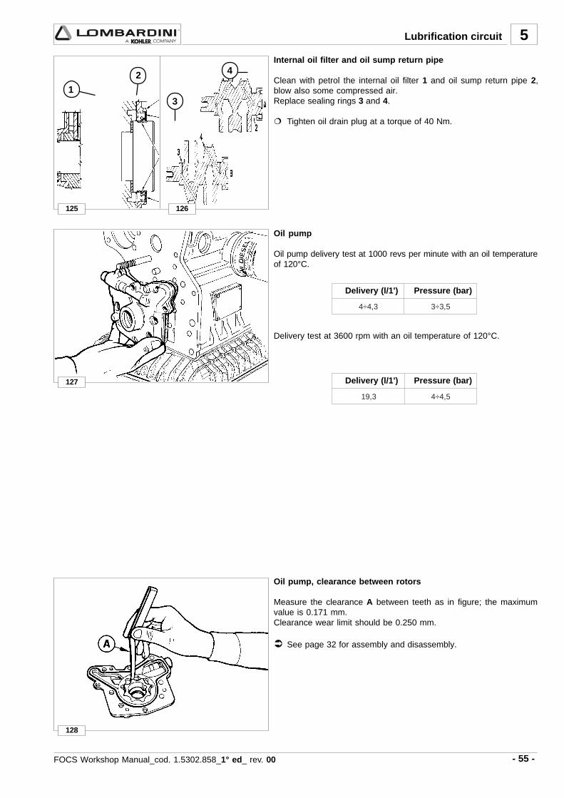
- 55 -FOCS Workshop Manual_cod. 1.5302.858_1° ed_ rev. 00
127
128
126
5
3,4÷4 5,3÷3
3,91 5,4÷4
125
1
2
3
4Internal oil filter and oil sump return pipe
Clean with petrol the internal oil filter 1 and oil sump return pipe 2,blow also some compressed air.Replace sealing rings 3 and 4.
Tighten oil drain plug at a torque of 40 Nm.
Oil pump
Oil pump delivery test at 1000 revs per minute with an oil temperatureof 120°C.
Delivery test at 3600 rpm with an oil temperature of 120°C.
Oil pump, clearance between rotors
Measure the clearance A between teeth as in figure; the maximumvalue is 0.171 mm.Clearance wear limit should be 0.250 mm.
See page 32 for assembly and disassembly.
Lubrification circuit
Delivery (l/1') Pressure (bar)
Delivery (l/1') Pressure (bar)
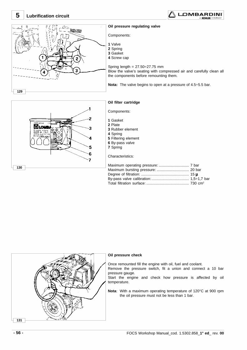
- 56 - FOCS Workshop Manual_cod. 1.5302.858_1° ed_ rev. 00
130
131
5
129
Oil filter cartridge
Components:
1 Gasket2 Plate3 Rubber element4 Spring5 Filtering element6 By-pass valve7 Spring
Characteristics:
Maximum operating pressure: ............................. 7 barMaximum bursting pressure: ............................... 20 barDegree of filtration: .............................................. 15 µµµµµBy-pass valve calibration: .................................... 1,5÷1,7 barTotal filtration surface: ......................................... 730 cm2
Oil pressure check
Once remounted fill the engine with oil, fuel and coolant.Remove the pressure switch, fit a union and connect a 10 barpressure gauge.Start the engine and check how pressure is affected by oiltemperature.
Nota: With a maximum operating temperature of 120°C at 900 rpmthe oil pressure must not be less than 1 bar.
Oil pressure regulating valve
Components:
1 Valve2 Spring3 Gasket4 Screw cap
Spring length = 27.50÷27.75 mmBlow the valve’s seating with compressed air and carefully clean allthe components before remounting them.
Nota: The valve begins to open at a pressure of 4.5÷5.5 bar.
Lubrification circuit

- 57 -FOCS Workshop Manual_cod. 1.5302.858_1° ed_ rev. 00
. .....................................................................................................................................................
. .....................................................................................................................................................
. .....................................................................................................................................................
. .....................................................................................................................................................
. .....................................................................................................................................................
. .....................................................................................................................................................
. .....................................................................................................................................................
. .....................................................................................................................................................
. .....................................................................................................................................................
. .....................................................................................................................................................
. .....................................................................................................................................................
. .....................................................................................................................................................
. .....................................................................................................................................................
. .....................................................................................................................................................
. .....................................................................................................................................................
. .....................................................................................................................................................
. .....................................................................................................................................................
. .....................................................................................................................................................
. .....................................................................................................................................................
. .....................................................................................................................................................
. .....................................................................................................................................................
. .....................................................................................................................................................
. .....................................................................................................................................................
. .....................................................................................................................................................
. .....................................................................................................................................................
. .....................................................................................................................................................
. .....................................................................................................................................................
. .....................................................................................................................................................
-Notes
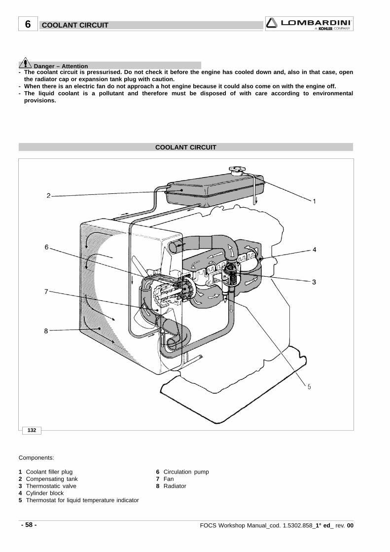
- 58 - FOCS Workshop Manual_cod. 1.5302.858_1° ed_ rev. 00
132
6
Components:
1 Coolant filler plug 6 Circulation pump2 Compensating tank 7 Fan3 Thermostatic valve 8 Radiator4 Cylinder block5 Thermostat for liquid temperature indicator
COOLANT CIRCUIT
Danger – Attention- The coolant circuit is pressurised. Do not check it before the engine has cooled down and, also in that case, open
the radiator cap or expansion tank plug with caution.- When there is an electric fan do not approach a hot engine because it could also come on with the engine off.- The liquid coolant is a pollutant and therefore must be disposed of with care according to environmental
provisions.
COOLANT CIRCUIT
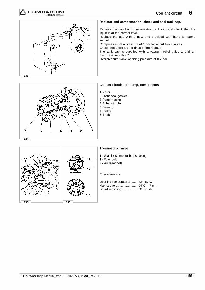
- 59 -FOCS Workshop Manual_cod. 1.5302.858_1° ed_ rev. 00
133
134
135 136
6
Radiator and compensation, check and seal tank cap.
Remove the cap from compensation tank cap and check that theliquid is at the correct level.Replace the cap with a new one provided with hand air pumpsocket.Compress air at a pressure of 1 bar for about two minutes.Check that there are no drips in the radiator.The tank cap is supplied with a vacuum relief valve 1 and anoverpressure valve 2.Overpressure valve opening pressure of 0.7 bar.
Thermostatic valve
1 - Stainless steel or brass casing2 - Wax bulb3 - Air relief hole
Characteristics:
Opening temperature: ........ 83°÷87°CMax stroke at: .................... 94°C = 7 mmLiquid recycling: ................. 30÷80 l/h.
Coolant circulation pump, components
1 Rotor2 Front seal gasket3 Pump casing4 Exhaust hole5 Bearing6 Pulley7 Shaft
Coolant circuit

- 60 - FOCS Workshop Manual_cod. 1.5302.858_1° ed_ rev. 00
138
139
140
7
137
Fuel pump drive rod projection - Assembly
Rotate the timing shaft so that the eccentric is on the base radiusand the drive rod is in place in its spherical seat in the control bush.The projection A of the drive rod 2 from the head level should be2÷2.5 mm.The check should be carried out with cam 1 at rest, as shown in thefigure.Tighten the two fuel pump fastening nuts at 24 Nm.Check the length of the drive rod and if it is not the right size,replace it.Drive rod length = 153.15÷153.35 mm.
Fuel lift pump
Components:1 Fuel lift pump2 Push rod3 Seal ring
The fuel pump is membrane type. It is driven by camshaft cam viaa drive rod.It is equipped with an external manual fuel lever.
Characteristics:With the control cam at 1500 rpm the delivery rate is 75 l/hours andthe self-adjusting pressure is at 0.55 to 0.65 bar.
Fuel filter detached from the tank (on request)
1 Air relief valve2 Bearing3 Cartridge4 Rubber element5 Filtering element
Cartridge characteristics:Filtering paper: ................................ PF 905Filtering surface: .............................. 2400 cm2
Degree of filtration: .......................... 2÷3 µµµµµMaximum operating pressure: ........ 4 bar
See page 18 for periodic maintenance details.
FUEL SYSTEM
Fuel feeding / injection circuit
Components: 1 Fuel Tank 2 Fuel filter 3 Fuel feeding tube 4 Fuel lift pump 5 lnjection pump 6 Injector 7 Fuel rail passage rubber joint 8 Injector exhaust pipe 9 Fuel tank cap10 Solenoid valve
Note: The tank complete with filter is supplied on request.

- 61 -FOCS Workshop Manual_cod. 1.5302.858_1° ed_ rev. 00
141
142
7
Pump/injector unit
Designed by LOMBARDINI, the pump/injector is exclusive to FOCSseries engines.The injection system includes three identical pumps/injector units,each one of which feeds a cylinder.
Pump/injector unit, components
1 Seeger ring A Ring nut 2 Tappet B O-ring 3 Stop plate C Nozzle 4 Plunger D Spacer 5 Spring E Pressure rod 6 Screw F Spring 7 Bearing G Spacer 8 Lever I Casing 9 Ring nut L Control spiral10 Plunger guide O-ring M Plunger guide11 Cylinder12 Delivery valve13 Gasket14 Spring15 Filler16 Pin When remounting the injector tighten ring nut A at 70 Nm17 O-ring18 Non-return valve19 O-ring20 Cap screw (old type)21 Metal gasket (new type)
Fuel system
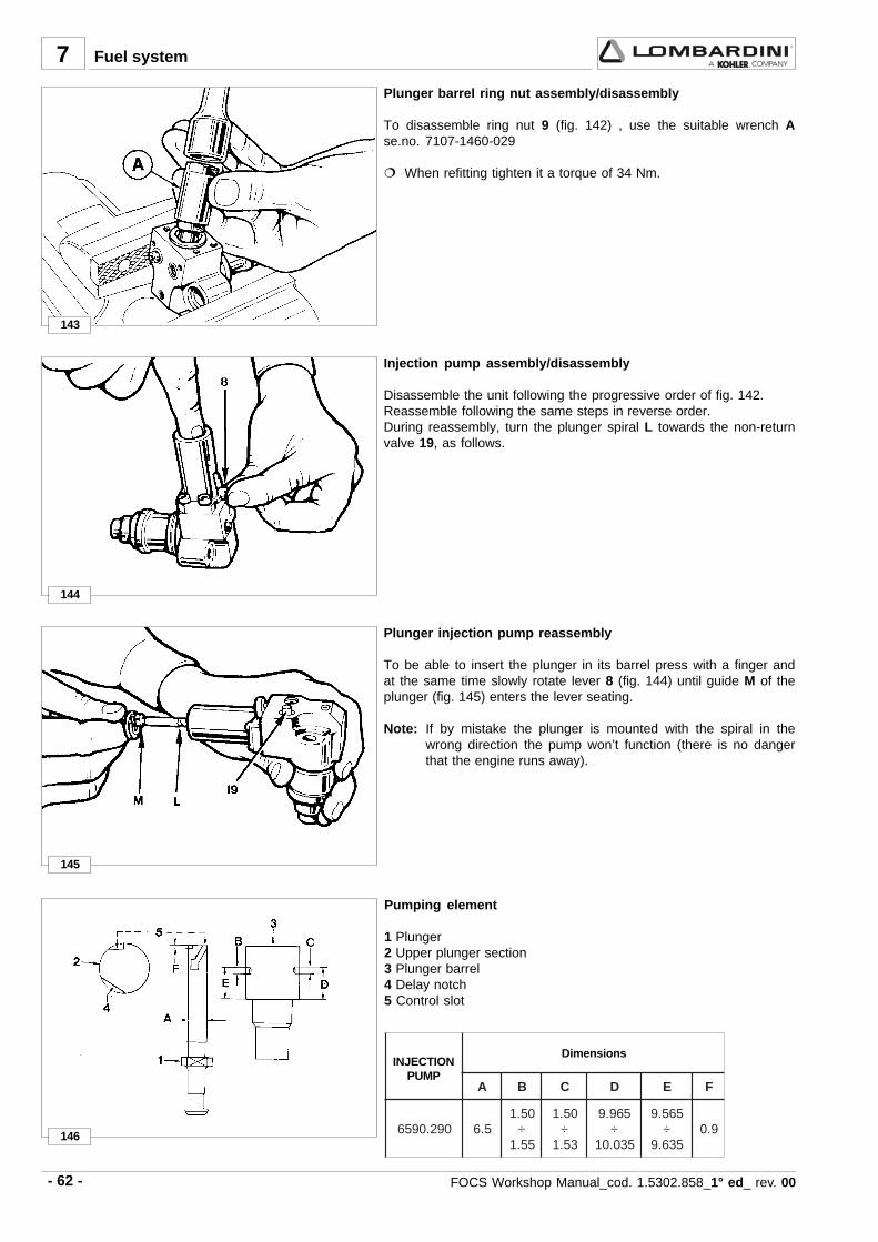
- 62 - FOCS Workshop Manual_cod. 1.5302.858_1° ed_ rev. 00
144
145
7
146
A B C D E F
092.0956 5.605.1
÷55.1
05.1÷
35.1
569.9÷
530.01
565.9÷
536.99.0
143
Plunger injection pump reassembly
To be able to insert the plunger in its barrel press with a finger andat the same time slowly rotate lever 8 (fig. 144) until guide M of theplunger (fig. 145) enters the lever seating.
Note: If by mistake the plunger is mounted with the spiral in thewrong direction the pump won’t function (there is no dangerthat the engine runs away).
Injection pump assembly/disassembly
Disassemble the unit following the progressive order of fig. 142.Reassemble following the same steps in reverse order.During reassembly, turn the plunger spiral L towards the non-returnvalve 19, as follows.
INJECTIONPUMP
Dimensions
Fuel system
Pumping element
1 Plunger2 Upper plunger section3 Plunger barrel4 Delay notch5 Control slot
Plunger barrel ring nut assembly/disassembly
To disassemble ring nut 9 (fig. 142) , use the suitable wrench Ase.no. 7107-1460-029
When refitting tighten it a torque of 34 Nm.

- 63 -FOCS Workshop Manual_cod. 1.5302.858_1° ed_ rev. 00
7
5,9 0063 32÷91
5,9 0021 42÷51
003 83÷53
147
235-4 6590.290 13° ÷ 14° > 3600 g/min
148
Rod stroke form max deliveryposition (mm)
start position
mm3/strokeRpm (*)
Fuel system
Pump/injector unit se.no. 6590.290 control data.
1 Delivery control lever on stop position.2 Delivery control lever on maximum delivery position.
Injector setting pressure: 140÷155 bar* Rpm rating is that of the crankshaft.
start position
REFERENCEN° CODE N°
INJECTIONADVANCE VALUE SPECIAL TOOLS
ADVANCE / INJECTOR SETTING ........ 1460.074T.D.C. ..................................................... 1460.048
OFFSET HOLES
REFERENCE NUMBER
CURRENT PUMP INJECTOR

- 64 - FOCS Workshop Manual_cod. 1.5302.858_1° ed_ rev. 00
7
150
152
151
149
Injector, spark arrester
Every time you remove the pump/injector you must replace thespark arrester, the copper gasket, the oil O-ring, as well as the 2 fuelO-rings.Insert the spark arrester in the injector housing with surface Apointing upwards.
Tighten simultaneously both nuts that fasten it to the head at 20Nm.For engines with the injectors fixed with self-locking nuts, tightenthe nuts at 23 Nm.
See page 18 for periodic maintenance details.
Injector, nozzle projection
To avoid excessive compression of the spark arrester A (fig. 152),check projection B of the nozzle (fig. 150).B = 6.80÷7.05 mm.If this measure is larger put spacer 2 between ring nut 1 and coppergasket 3.0.25 mm thick spacers are available.
Fuel system
Setting of injector
Remove the non-return valve leaving its metal gasket and fit a capscrew in its place, that is part of tooling 7107-1460-074.Mount then head 1 and coupling 2.Then connect a hand pump as shown in the picture.The pressure setting must be 140÷155 mm bar.

- 65 -FOCS Workshop Manual_cod. 1.5302.858_1° ed_ rev. 00
7
ααααα
092-0956 4-532 0063> °51÷°31
ααααα )mm(
°81 864.2
°71 502.2
°61 659.1
°51 127.1
°41 105.1
°31 692.1
°21 501.1
°11 039.0
°01 967.0
°9 326.0
°8 394.0
°7 873.0
°6 772.0
153
154
Fuel system
Code Reference n° Rpm
Injection advance
Injection advance control and regulation
- Dismount the rocker arm cover (see page 32).- Position the device on the head, in contact with cylinder no. 1.- Mount the dial gauge on the valve controlled by tool ref. 1460.048.- Via lever 1 of the tool, open the valve until it comes into contact
with the piston.- Then rotate the crankshaft until the TDC is read in the dial gauge.
Then reset the hundredths.- Remove the fuel pipes.- Remove the O-ring in contact with the non-return valve and
replace it with the appropriate gasket - equipment component partref. 1460.074. Once the check has been completed, remove thegasket and refit the O-ring.Connect tool 1460.074 on pump 1. This will automatically positionthe control lever to the maximum delivery. The tool is providedwith 3÷4 couplings for connection to a tank that must be not lowerthan 30 cm from the pumps level. Coupling 2 is equipped with aplastic pipe 5 with internal drip collecting wire.
- Put cylinder 1 under compression and open the tank tap. Fueldiesel will start to flow out from coupling 2.
- Slowly rotate the engine towards TDC 1 until the diesel fuel stopsleaking out.
- At this point with lever 1 (of fig. 153) move again the valve until ittouches the piston and read on the dial gauge how manyhundredths are missing from the previously reset value (TDC).
- To convert hundredths into degrees, consult the table below.- Repeat the operation on the other cylinders.

- 66 - FOCS Workshop Manual_cod. 1.5302.858_1° ed_ rev. 00
7
155
156
157 158
159
Static injection advance tuning
If the injection advance value found does not correspond to thepreviously described value, adjust the screw E and repeat the test.Rotating screw E by ½ turn will change the injection advance by 5°.If turned clockwise, injection is advanced.In the opposite direction, injection is delayed.
Fuel system
Test head B assembly
Remove fuel pipe A and mount one test head B in its place perpump/injector.The test heads complete with pipes are supplied together withinstrument ref. 7104-1460-069.
Preliminary steps to pump/injector unit delivery balancing test
Closing the oilhole
To perform this test you must remove the rocker arms cover andclose hole 1 with an M 8x1.25 or M 10x1.5 screw (on latest modelengines) not longer than 8 mm. Also remove the copper gasket.If the camshaft and rocker arms are dry, lubricate them with engineoil.
Note: If you only want to check the nozzle it is not necessary tobalance the deliveries; provided that when you dismount therod you do not loosen adjusting screws 1 and 2 (fig. 160).
Instrument connection
Place the instrument 1, se.no. 7104-1460-127 at least 20 cm abovethe pump/injector level.Connect pipe A (outlet from every instrument test piece) with pipe A(inlet of every pump/injector) and pipe B (return to the instrument)with pipe B (outlet from the pump/injector).Open tap 2 and 3 of each pipe and fill the instrument with diesel.Start the engine and bring it to 1500 rpm idle running.Close the fuel supply to the engine from the instrument’s tank usinglever 4 and after 1 minute observe the levels in the test piece.If a level goes down more than the others it is necessary to decreasethe delivery of the corresponding pump (see below) and vice versato increase the delivery if the level increases.

- 67 -FOCS Workshop Manual_cod. 1.5302.858_1° ed_ rev. 00
7
160
Fuel system
Injection pumps delivery balancing
In case the balancing error read on the test pieces is greater than 2cm³/min, then injection pumps deliveries should be adjusted.Plate 4 and rod 3 are blocked by screws 1 and 2. Loosen them.Move plate 4 rightwards with respect to rod 3 if you want toincrease delivery.If moved leftwards delivery decreases. Make very small movementswith the plate.
Tighten screws 1 and 2 at a torque of 1,1 Nm.
Note: Each time a pump/injector is replaced it is necessary tobalance the deliveries.

- 68 - FOCS Workshop Manual_cod. 1.5302.858_1° ed_ rev. 00
8
161
162
1
Alternator, 14V 33A
Nominal voltage ................. 12VNominal current output ...... 55AMaximum Rpm .................. 18.000 giri/1'Rotation (viewed at puley end): Clockwise
Tighten nut 1 at a torque of 60÷70Nm.
Alternator, 14V 33A - Performance Curve
The curve was obtained at room temperature of +25°C with 13,5 Vbattery voltage.
Note: The rpm shown on the table are referred to the alternator.Engine rpm/alternator rpm ratio, with driving pulley diameter105 mm = 1:1,79.
ELECTRIC SYSTEM

- 69 -FOCS Workshop Manual_cod. 1.5302.858_1° ed_ rev. 00
8
6,1 66 013 88 033
163
Electric System
Electric starting layout (12V) with alternator 14V 33A
1 Alternator 2 Starter Motor 3 Battery 4 Glow Plugs 5 Coolant temperature thermistor 6 Glow Plug Controller / Timer 7 Key Switch 8 System Fuse, 50 A 9 Fuse (Accessory)- 5A10 Fuel Solenoid Valve11 Glow Plug Indicator Lamp12 Coolant High Temperature Lamp13 Coolant High Temperature Switch14 Oil Pressure (Low) Lamp15 Oil Pressure Switch16 Alternator Charging Lamp17 Air Filter High Restriction Indicator Lamp18 Air Filter Restriction Switch19 Low Fuel Level Lamp20 Low Fuel Level Switch21 Diode
A Accessory PositionB Off PositionC On PositionD Starting Position
For electrical connections of the pre-heating gear case, seefigure 170.
Note: Battery 3 not supplied by LOMBARDINI.For assembly we recommend a battery with the followingcharacteristics, see table below.
Starter motor class(epicyclic type) Kw
Capacity K20 -Ah
Rapid dischargeintensity
(DIN Standards at -18°C) A
Capacity K20 -Ah
Rapid dischargeintensity
(DIN Standards at -18°C) A
Normal starting conditionsHeavy-duty starting conditions
(max allowed)
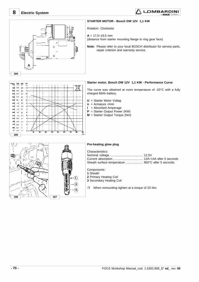
- 70 - FOCS Workshop Manual_cod. 1.5302.858_1° ed_ rev. 00
8
164
165
A
166 167
STARTER MOTOR - Bosch DW 12V 1,1 KW
Rotation: Clockwise
A = 17,5÷19,5 mm(distance from starter mounting flange to ring gear face)
Note: Please refer to your local BOSCH distributor for service parts,repair criterion and warranty service.
Starter motor, Bosch DW 12V 1,1 KW - Performance Curve
The curve was obtained at room temperature of -20°C with a fullycharged 66Ah battery.
U = Starter Motor Voltagn = Armature r/minI = Absorbed AmperageP = Starter Output Power (KW)M = Starter Output Torque (Nm)
Electric System
Pre-heating glow plug
Characteristics:Nominal voltage ........................................ 12,5VCurrent absorption .................................... 12A÷14A after 5 secondsSheath surface temperature ..................... 850°C after 5 seconds.
Components:1 Sheath2 Primary Heating Coil3 Secondary Heating Coil
When remounting tighten at a torque of 20 Nm.

- 71 -FOCS Workshop Manual_cod. 1.5302.858_1° ed_ rev. 00
8
068110007072400420001
045
03-02-01-
002+04+
04÷0303÷5202÷6181÷3111÷7
8÷6
091÷071
168
171 172
170
3 4
1
576
2
169
Electric System
Pre-heating plug control unit with coolant temperature sensor
To avoid white smoke immediately following start-up post-heat forabout 180 seconds, see table
Post-heat
Glow-plug heat time(sec.)
Pre-heatCoolant temp.
°CResistance
(ohm)
Thermistor input
Temperature sensor for control unit
In engines fitted with the above-mentioned type of control unit, theintroduction of the glow plugs depends on a temperature sensor thatvaries preheating temperature in relation to the coolant temperature.
Characteristics:
Temperature range ............... -30 ÷ +50°CVoltage range........................ 6÷24 VTemperature max. ................ 150°CMax. tightening torque. ......... 30 Nm.
Wiring diagram for pre-heating gear case
1 6 mm2 cable to "30" terminal of key-switch2 1,5 mm2 cable to ground3 1,5 mm2 cable to "15/54" terminal of key-switch4 2,5 mm2 cable to "50" terminal of key-switch5 6 mm2 cable to glowplugs6 1 mm2 cable to glowplugs warning light (max.2w)7 1 mm2 cable to water temperature transducer
Tim
e (s
ec.)
Pre glow time at 11v
Temp. °C
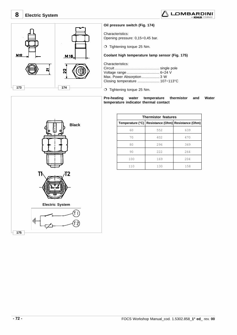
- 72 - FOCS Workshop Manual_cod. 1.5302.858_1° ed_ rev. 00
8
175
06 255 936
07 204 074
08 692 943
09 222 462
001 961 402
011 031 851
173 174
Black
Electric System
Electric System
Thermistor features
Temperature (°C) Resistance (Ohm) Resistance (Ohm)
Oil pressure switch (Fig. 174)
Characteristics:Opening pressure: 0,15÷0,45 bar.
Tightening torque 25 Nm.
Coolant high temperature lamp sensor (Fig. 175)
Characteristics:Circuit ............................................. single poleVoltage range................................. 6÷24 VMax. Power Absorption .................. 3 WClosing temperature ...................... 107÷113°C
Tightening torque 25 Nm.
Pre-heating water temperature thermistor and Watertemperature indicator thermal contact

- 73 -FOCS Workshop Manual_cod. 1.5302.858_1° ed_ rev. 00
. .....................................................................................................................................................
. .....................................................................................................................................................
. .....................................................................................................................................................
. .....................................................................................................................................................
. .....................................................................................................................................................
. .....................................................................................................................................................
. .....................................................................................................................................................
. .....................................................................................................................................................
. .....................................................................................................................................................
. .....................................................................................................................................................
. .....................................................................................................................................................
. .....................................................................................................................................................
. .....................................................................................................................................................
. .....................................................................................................................................................
. .....................................................................................................................................................
. .....................................................................................................................................................
. .....................................................................................................................................................
. .....................................................................................................................................................
. .....................................................................................................................................................
. .....................................................................................................................................................
. .....................................................................................................................................................
. .....................................................................................................................................................
. .....................................................................................................................................................
. .....................................................................................................................................................
. .....................................................................................................................................................
. .....................................................................................................................................................
. .....................................................................................................................................................
. .....................................................................................................................................................
-Notes
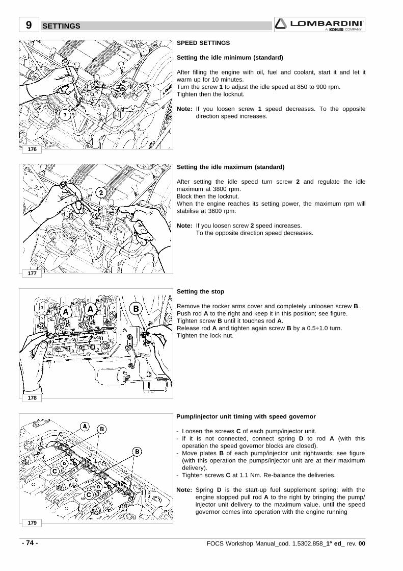
- 74 - FOCS Workshop Manual_cod. 1.5302.858_1° ed_ rev. 00
176
177
178
179
9
SPEED SETTINGS
Setting the idle minimum (standard)
After filling the engine with oil, fuel and coolant, start it and let itwarm up for 10 minutes.Turn the screw 1 to adjust the idle speed at 850 to 900 rpm.Tighten then the locknut.
Note: If you loosen screw 1 speed decreases. To the oppositedirection speed increases.
Setting the stop
Remove the rocker arms cover and completely unloosen screw B.Push rod A to the right and keep it in this position; see figure.Tighten screw B until it touches rod A.Release rod A and tighten again screw B by a 0.5÷1.0 turn.Tighten the lock nut.
Pump/injector unit timing with speed governor
- Loosen the screws C of each pump/injector unit.- If it is not connected, connect spring D to rod A (with this
operation the speed governor blocks are closed).- Move plates B of each pump/injector unit rightwards; see figure
(with this operation the pumps/injector unit are at their maximumdelivery).
- Tighten screws C at 1.1 Nm. Re-balance the deliveries.
Note: Spring D is the start-up fuel supplement spring: with theengine stopped pull rod A to the right by bringing the pump/injector unit delivery to the maximum value, until the speedgovernor comes into operation with the engine running
Setting the idle maximum (standard)
After setting the idle speed turn screw 2 and regulate the idlemaximum at 3800 rpm.Block then the locknut.When the engine reaches its setting power, the maximum rpm willstabilise at 3600 rpm.
Note: If you loosen screw 2 speed increases.To the opposite direction speed decreases.
SETTINGS
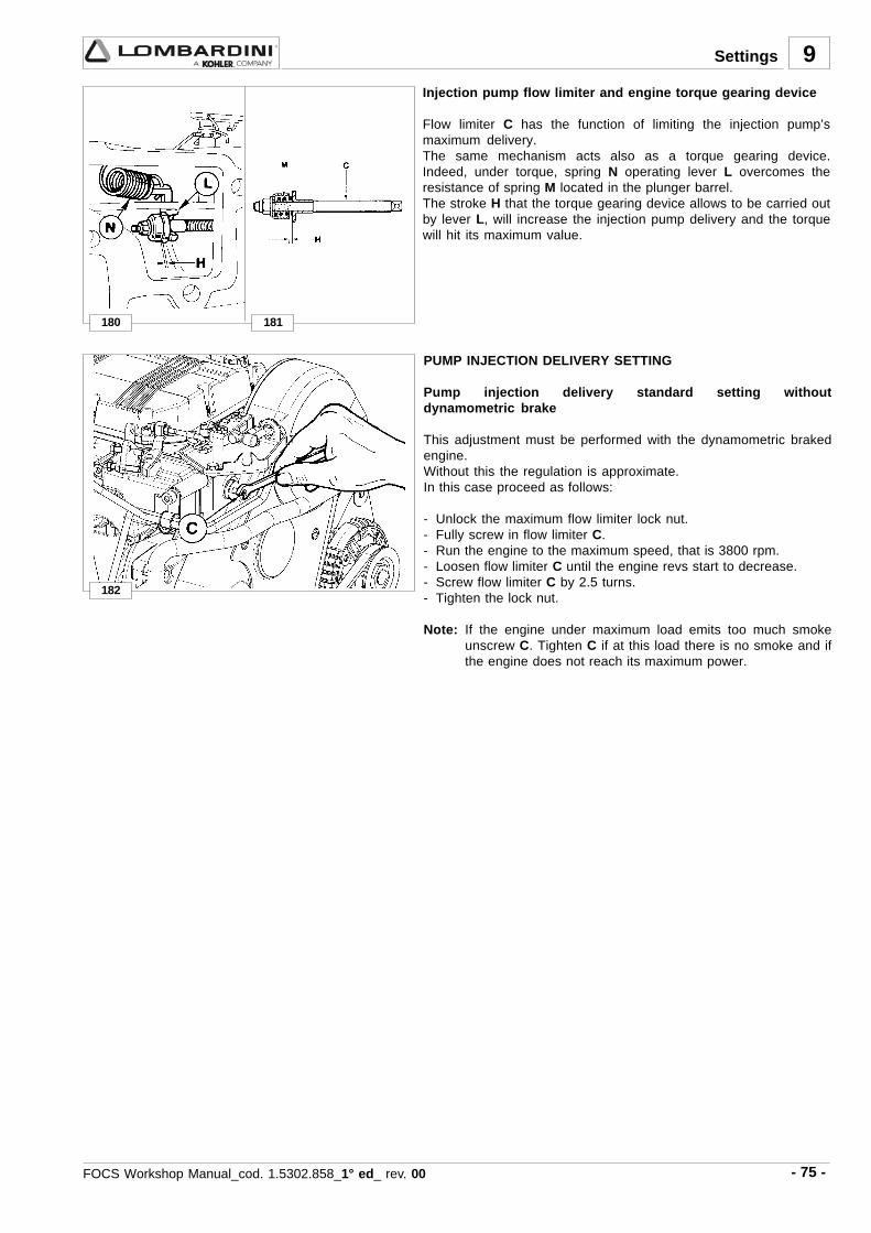
- 75 -FOCS Workshop Manual_cod. 1.5302.858_1° ed_ rev. 00
180 181
9
182
Injection pump flow limiter and engine torque gearing device
Flow limiter C has the function of limiting the injection pump’smaximum delivery.The same mechanism acts also as a torque gearing device.Indeed, under torque, spring N operating lever L overcomes theresistance of spring M located in the plunger barrel.The stroke H that the torque gearing device allows to be carried outby lever L, will increase the injection pump delivery and the torquewill hit its maximum value.
Settings
PUMP INJECTION DELIVERY SETTING
Pump injection delivery standard setting withoutdynamometric brake
This adjustment must be performed with the dynamometric brakedengine.Without this the regulation is approximate.In this case proceed as follows:
- Unlock the maximum flow limiter lock nut.- Fully screw in flow limiter C.- Run the engine to the maximum speed, that is 3800 rpm.- Loosen flow limiter C until the engine revs start to decrease.- Screw flow limiter C by 2.5 turns.- Tighten the lock nut.
Note: If the engine under maximum load emits too much smokeunscrew C. Tighten C if at this load there is no smoke and ifthe engine does not reach its maximum power.

- 76 - FOCS Workshop Manual_cod. 1.5302.858_1° ed_ rev. 00
wK hwK/g
30010022 31 35÷75 462÷852
0063 91 55÷45 492÷982
9
183
Specific fuel consumption
Time (sec) per100 cm3
Power*( N curve )
RpmEngine
Required settings (as most commonly applies)
* Refers to power curve N (see pages 16) and after run-in.
Settings
Pump/injector unit delivery setting with braked engine
1) Run the engine to the maximum speed.2) Screw flow limiter C (see fig. 182).3) Load the engine up to the power and number of revs required by
the application’s manufacturer.4) Check that consumption is within the values allowed for in the
settings table (see below).If consumption is not within the given figures, it is necessary tochange the balance conditions shown to the brake, altering theload and the speed governor. Redo the consumption check on thestabilised engine.
5) Unscrew limiter C until the engine rpm start to decrease. Lock thelimiter using the lock nut.
6) Completely release the brake and check the rpm at which theengine stabilises.The performance of the speed governor must meet the classrequired by the application’s manufacturer.
7) Stop the engine.8) Recheck the valve clearance with the engine cold.

- 77 -FOCS Workshop Manual_cod. 1.5302.858_1° ed_ rev. 00
184
9
E.G.R. calibration
Mount a T-branch on vacuum valve - E.G.R. valve connection pipe1, and connect it to a vacuum pressure gauge with 1 bar bottomscale so as to be able to read the degree of vacuum within the pipe.
Note: It is also possible to use a mercury column, 1 metre long,since the maximum suction pressure exerted by the vacuumpump is 720 mmHg.
Adjust the position of the accelerator lever via the regulator block, sothat the internal adjusting nut 2, is about 5 mm from the end of thethread.
Accelerate the engine up to 3.600 rpm (with valve closed: thismeans that the value showed on the vacuum pressure gauge or onthe mercury column should be 0.In case it is different from zero, adjust the regulator block nuts tomove it, in relation to the rod 3, in the direction that goes from theflywheel to the timing.
With the brake at a braking curve N=constant, “load” the engineslowing it down to 2.800 rpm.
Acting on the accelerator look for the E.G.R. valve closing point(pressure of the vacuum pressure gauge or mercury gauge equal tozero).
Note: Pay attention to determine the precise closing point: byslightly accelerating the engine the vacuum value in theE.G.R. operation pipe should immediately increase.
Measure the engine consumption in order to calculate the mm3/stroke value.
If the calculated value is less than 18.8 mm3/stroke, adjust theadjusting nut making it closer to the end of the rod 3 to “increase thecalibration”.
When the required value of 18.8 mm3/stroke has been reached (anda power of around 7 KW) tighten the adjusting nuts.
Settings

- 78 - FOCS Workshop Manual_cod. 1.5302.858_1° ed_ rev. 00
10 STORAGE
- When the engines are not for more than 6 months, they have to be protected performing the operations described inthe following pages.
- If the engine is not to be used for extensive periods, check the storage area conditions and the type of packaging andmake sure that these are suitable for correct storage.If necessary, cover the engine with a proper protective sheet.
- Avoid storing the engine in direct contact with the ground, in environments that are humid and exposed to bad weather,near high voltage electric lines, etc.
Important
If, after the first 6 months, the engine is still not used, it is necessary to carry out a further measure to extendthe protection period (see “Protective treatment”).
1 - Pour in the engine housing AGIP RUSTIA C protective oil up to the maximum level.2 - Fill up with fuel containing 10% AGIP RUSTIA NT.3 - Make sure that the coolant is up to the maximum level.4 - Start the engine and keep it idle at minimum speed for some minutes.5 - Bring the engine to ¾ of the maximum speed for 5÷10 minutes.6 - Turn off the engine.7 - Empty out completely the fuel tank.8 - Spray SAE 10W on the exhaust and intake manifolds.9 - Seal the exhaust and intake ducts to prevent foreign bodies from entering.10 - Thoroughly clean all external parts of the engine using suitable products.11 - Treat non-painted parts with protective products (AGIP RUSTIA NT).12 - Loosen the alternator/fan belt.13 - Cover the engine with a proper protective sheet.
Caution - Warning
In countries in which AGIP products are not available, find an equivalent product (with specifications: MIL-L-21260C).
Important
Maximum every 24 months of inactivity, the engine must be started up by repeating all "Engine Storage"operations.
ENGINE STORAGE
PROTECTIVE TREATMENT

- 79 -FOCS Workshop Manual_cod. 1.5302.858_1° ed_ rev. 00
10Storage
PREPARING THE ENGINE FOR OPERATION AFTER PROTECTIVE TREATMENT
After the storage period and before starting up the engine and preparing it for operation, you need to perform certainoperations to ensure maximal efficiency conditions.
1 - Remove the protective sheet.2 - Remove any sealing devices from the exhaust and intake ducts.3 - Use a cloth soaked in degreasing product to remove the protective treatment from the external parts.5 - Inject lubricating oil (no more than 2 cm3) into the intake ducts.6 - Adjust the alternator/fan belt tension.7 - Turn the engine manually to check the correct movement and smoothness of the mechanical parts.8 - Refill the tank with fresh fuel.9 - Make sure that the oil and the coolant are up to the maximum level.10 - Start the engine and after some minutes bring it to ¾ of the maximum speed for 5-10 minutes.11 - Turn off the engine.12 - Remove the oil drain plug (see “Oil replacement”) and discharge the AGIP RUSTIA NT protective oil while the engine is
hot.13 - Pour new oil (see "Table of lubricants") up to the maximum level.14 - Replace the filters (air, oil, fuel) with original spare parts.15 - Empty the cooling circuit completely and pour in the new coolant up to the maximum level.
Caution - Warning
Over time, a number of engine components and lubricants lose their properties, so it is important consideringwhether they need replacing, also based on age (see Replacement table).
Important
Maximum every 24 months of inactivity, the engine must be started up by repeating all "Engine Storage"operations.

- 80 - FOCS Workshop Manual_cod. 1.5302.858_1° ed_ rev. 00
1,140
2015109
6010
105
24408
20*40
12**5015
7360802540***4
80
M 3 spec.8x1
12x1,2520X1,5
66x1
M 10M 6
M 65x0,88x1,5M 10
8x1,25M 8
M 10
M 630x1,5
10x1,2510
12x1,56x1
16x1,5 sin.10x1,2512x1,512x1,5
18TCEI 4x1,5
10x1,5
45÷46 - p. 3497 - p. 46
166÷167 - p. 70
39 - p. 33107÷111 - p. 48
80 - p. 41
34 - p. 31
140 - p. 6025 - p. 29
152 - p. 6451 - p. 35
73÷79 - p. 40÷417÷8 - p. 25
12 - p. 2620 - p. 28
173 - p. 72125÷126 - p. 55
95÷96 - p. 4547 - p. 3411 - p. 26
270270638
Silicon7091
270242
242
11
Riference(figure and page n°)
TORQUE SPECIFICATIONS AND USE OF SEALANT
TABLE OF TIGHTENING TORQUES FOR THE MAIN COMPONENTS
POSITIONTorque( Nm )
Diam. & pitch( mm ) Sealant
Injection pump control rodConnecting rod ****
Glow-plugsOil filter cartridge (M 20x1,5 union)Camshaft bearing (M 6 screws)Rocker arm coverMain bearing capsOil pan
Camshaft bearing support screwGlow-plug cable nutsFuel lift pump nutsBelt tensioner nutExternal Stop control lever nutPump/injector unit fixing nutRocker arm assembly support nutFuel pump camFlywheel side oil seal ring flangePre-combustion chamber ring nutVacuum pump fixing screwsBelt tensionerCrankcaseSpeed governor lever screwDriving pulleyCamshaft timing pulleyOil pressure switchOil drain plugCylinder headùInjection pipeFlywheel
* Tighten the two nuts that fasten each pump/injector unit at the same time. For engines with the injectors fixed with self-locking nuts, tighten the nuts at 23 Nm.
** Tighten these in two phases: the first phase at 100 Nm, the second phase at 180 Nm. See page 40-41, figures 73-79.*** See page 45**** Aluminium connecting rod with 35 Nm tightening torque.
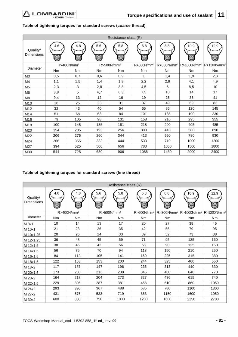
- 81 -FOCS Workshop Manual_cod. 1.5302.858_1° ed_ rev. 00
M3
M4
M5
M6
M8
M10
M12
M14
M16
M18
M20
M22
M24
M27
M30
R>400N/mm2 R>500N/mm2 R>600N/mm2 R>800N/mm2 R>1000N/mm2 R>1200N/mm2
Nm
0,7
1,5
3
5
13
25
43
68
105
145
205
275
355
525
725
Nm
0,6
1,4
2,8
4,7
12
23
40
63
98
135
193
260
333
500
680
Nm
0,9
1,8
3,8
6,3
16
31
54
84
131
181
256
344
444
656
906
Nm
1
2,2
4,5
7,5
19
37
65
101
158
218
308
413
533
788
1088
Nm
1,4
2,9
6
10
25
49
86
135
210
290
410
550
710
1050
1450
4.6 4.8 5.6 5.8 6.8 8.8 10.9 12.9
Nm
0,5
1,1
2,3
3,8
9,4
18
32
51
79
109
154
206
266
394
544
Nm
1,9
4,1
8,5
14
35
69
120
190
295
405
580
780
1000
1500
2000
Nm
2,3
4,9
10
17
41
83
145
230
355
485
690
930
1200
1800
2400
R>400N/mm2 R>500N/mm2 R>600N/mm2 R>800N/mm2 R>1000N/mm2 R>1200N/mm2
Nm
10
21
20
36
38
56
84
122
117
173
164
229
293
431
600
Nm
14
28
26
48
45
75
113
163
157
230
218
305
390
575
800
Nm
13
26
24
45
42
70
105
153
147
213
204
287
367
533
750
Nm
17
35
33
59
56
94
141
203
196
288
273
381
488
719
1000
Nm
20
42
39
71
68
113
169
244
235
345
327
458
585
863
1200
Nm
27
56
52
95
90
150
225
325
313
460
436
610
780
1150
1600
Nm
38
79
73
135
125
210
315
460
440
640
615
860
1100
1600
2250
Nm
45
95
88
160
150
250
380
550
530
770
740
1050
1300
1950
2700
4.6 4.8 5.6 5.8 6.8 8.8 10.9 12.9
11
M 8x1
M 10x1
M 10x1,25
M 12x1,25
M 12x1,5
M 14x1,5
M 16x1,5
M 18x1,5
M 18x2
M 20x1,5
M 20x2
M 22x1,5
M 24x2
M 27x2
M 30x2
Table of tightening torques for standard screws (coarse thread)
Resistance class (R)
Quality/Dimensions
Diameter
Resistance class (R)
Quality/Dimensions
Diameter
Table of tightening torques for standard screws (fine thread)
Torque specifications and use of sealant

- 82 - FOCS Workshop Manual_cod. 1.5302.858_1° ed_ rev. 00
7107-1460-127
7107-1460-030
7107-1460-053
7107-1460-029
7107-1460-027
7107-1460-031
7107-1460-047
7107-1460-048
7107-1460-049
7107-1460-074
12
Injection pumps delivery balancinginstrument
Precombustion chamber extractor
Sheet metal for insertion of main bearings inthe crankcase
Ring nut wrench for fastening pump/injectorpumping element
Precombustion chamber wrench
Precombustion chamber adjusting rod
Device for mounting valve guide gasket,intake and exhaust side
Valve lowering device for injection advancecontrol
Timing belt tightening tool
Tool for injection advance control and settingof injector for pump/injector unit: se.no.6590-290
SPECIAL TOOLS DESCIPTION PART N°.
SPECIAL TOOLS

- 83 -FOCS Workshop Manual_cod. 1.5302.858_1° ed_ rev. 00
. .....................................................................................................................................................
. .....................................................................................................................................................
. .....................................................................................................................................................
. .....................................................................................................................................................
. .....................................................................................................................................................
. .....................................................................................................................................................
. .....................................................................................................................................................
. .....................................................................................................................................................
. .....................................................................................................................................................
. .....................................................................................................................................................
. .....................................................................................................................................................
. .....................................................................................................................................................
. .....................................................................................................................................................
. .....................................................................................................................................................
. .....................................................................................................................................................
. .....................................................................................................................................................
. .....................................................................................................................................................
. .....................................................................................................................................................
. .....................................................................................................................................................
. .....................................................................................................................................................
. .....................................................................................................................................................
. .....................................................................................................................................................
. .....................................................................................................................................................
. .....................................................................................................................................................
. .....................................................................................................................................................
. .....................................................................................................................................................
. .....................................................................................................................................................
. .....................................................................................................................................................
-Notes

. .....................................................................................................................................................
. .....................................................................................................................................................
. .....................................................................................................................................................
. .....................................................................................................................................................
. .....................................................................................................................................................
. .....................................................................................................................................................
. .....................................................................................................................................................
. .....................................................................................................................................................
. .....................................................................................................................................................
. .....................................................................................................................................................
. .....................................................................................................................................................
. .....................................................................................................................................................
. .....................................................................................................................................................
. .....................................................................................................................................................
. .....................................................................................................................................................
. .....................................................................................................................................................
. .....................................................................................................................................................
. .....................................................................................................................................................
. .....................................................................................................................................................
. .....................................................................................................................................................
. .....................................................................................................................................................
. .....................................................................................................................................................
. .....................................................................................................................................................
. .....................................................................................................................................................
. .....................................................................................................................................................
. .....................................................................................................................................................
. .....................................................................................................................................................
. .....................................................................................................................................................
- 84 - Manuale officina FOCS_cod. 1.5302.350_7° ed_ rev. 06
- Notes


La Lombardini si riserva il diritto di modificare in qualunque momento i dati contenuti in questa pubblicazione.Lombardini se rèserve le droit de modifier, à n'importe quel moment, les données reportées dans cette publication.
Data reported in this issue can be modified at any time by Lombardini.Lombardini behält sich alle Rechte vor, diese Angabe jederzeit zu verändern.
La Lombardini se reserva el derecho de modificar sin previo aviso los datos de esta publicación.
42100 Reggio Emilia – Italia - ITALYVia Cav. del Lavoro Adelmo Lombardini, 2 - Cas. Post. 1074
Tel. (+39) 0522 3891 - Telex 530003 Motlom I – Telegr.: LombarmotorR.E.A. 227083 - Reg. Impr. RE 10875
Cod. fiscale e Partita IVA 01829970357 - CEE Code IT 01829970357
E-MAIL: [email protected]: http://www.lombardini.it
cod. 1-5302-858
1003 FOCS Engine Series


![[Manual] Lombardini](https://img.dokumen.tips/doc/110x75/544de6e9af7959f7178b4fa3/manual-lombardini.jpg)