Embed Size (px)
Citation preview
United States Patent [19]
Saito et al.
USOO5867824A
5,867,824 Feb. 2, 1999
Patent Number:
Date of Patent:
[11]
[45]
[54] WORKFLOW METHOD AND SYSTEM OTHER PUBLICATIONS THEREFOR
Sandy Kemsley, “The Evolution of Work?oW (Electronic [75] Inventors: Takashi Saito, Koube; Shunsuke Work?oW Management Systems)”, Computing Canada, v
Akifuji, Wakou; Hiroshi Tsuji, Itami; 20, n 4, p. 32, Feb. 16, 1994. Hiroshi Majima> Yokohama; Tetsuji Nina Burns, “Just Go With the (Work)?oW”, PC Week, v 10, Toge, Koube, 9110f Japan 11 47, pp. N5—N6, Nov. 1993.
[73] Assignee. Hitachi Ltd_ Tokyo Japan NeW Work?oW System “Goes Beyond StaffWare, Work ' ’ ’ ’ horse and Rhapsody”, Computergram International, n 1809.
[21] Appl. No.: 546,912 NOV‘ 1991' _ Gordon, Martin; In good Form (WordPerfect Informs) (Soft
I22l Flled? Oct- 23, 1995 Ware Review) (Evaluation); PC User; n213, p55(1), Jun. 16,
[30] Foreign Application Priority Data 1993'
Oct. 26, 1994 [JP] Japan .................................. .. 6-262208 Primary Examiner_Emanue] Todd VoeltZ
[51] Int. Cl? .................................................... .. G06F 17/60 Assistant Examiner—w?liam N- Hughet [52] U S C] 705 /9_ 380/23 380/25 Attorney, Agent, or Firm—Fay Sharpe Beall Fagan Minnich
395/187.01; 395/200.68; 395/200.69; 395/2007; 8‘ McKee 395/200.71; 395/200.72; 395/200.73; 395/200.74; [57] ABSTRACT
707/9 [58] Field of Search ................................... .. 395/207, 209, A WOIk?OW System Comprising a plurality of WOrk?OW
395/18701, 200_68_200_74; 380/23, 25; subsystems connected to a LAN (Local Area Network), 705/9; 707/9 these Work?oW subsystems being composed of servers and
clients, and provides a Work?oW system Which permits an [56] References Cited integrated management of the de?nitions of the business
processes placed under decentralized management, through us PATENT DOCUMENTS the server managing shipping documents, BPs (Business
4503 499 3/1985 Mason et a1__ Processes) describing shipping routes of shipping docu 4:932:026 6/1990 Dev 6] a] _ ments in the subsystem, and business process connection
data to connect the BPs. FOREIGN PATENT DOCUMENTS
94/18620 8/1994 WIPO . 2 Claims, 10 Drawing Sheets
SERVER 110
SP DEFINITION 150 SP DEFINITION MANAGEMENT UNIT 240]
BP DEFINITION 3 I EQANCE EXIT DOCUMENT MANAGEMENT UNIT 220
d 1 450 CI 2 45 d 3 450 O O “M no e no e no e node4 “0P9 node “0519 nofe OUT IN OUT IN OUT IN
QUEUE QUEUE QUEUE QUEUE QUEUE QUEUE
420 410 , |420| 410' I 420 I 410 E ‘a = :. a'E "3E / / \ 1
430 /\// | 430 ’\3\ \ L / / NETWORK CONTROLLER \ \ 210 |
LAN //\~ 440 \ \/\ 440 <3 / I
130 CLIENT , _ CLIENT
U.S. Patent Feb. 2, 1999 Sheet 1 0f 10 5,867,824
FIG. 1
14o
/ WAN
sERvER 11o sERvER 110
‘ED 160 ‘52) BP SHIPPING BP CON- BP DEFI- DOCU- DEFI.
13o NITION MENT 130 NITION
LAN LAN . . .
CLIENT CLIENT CLIENT
L k L IE! IE! IE!
WORKFLOW MANAGEMENT SUBSYSTEM 180 WORKFLOW MANAGEMENT SUBSYSTEM 180
FIG. 2
NETwoRK 526°
SERVER 110
I NETwoRKCoNTRoLLER 21(? I
I DOCUMENT MANAGEMENT UNIT 220
BP CONNECTION BP DEFINITION DATA MANAG E- MANAGEMENT MENT UNIT 230 UNIT 240
I I I l/O CoNTRoLLER 25o ]
I
DEFI‘ NITION
Sheet 2 0f 10 5,867,824 U.S. Patent Feb. 2, 1999
FIG. 3
BP DEFINITION 2 353 N‘ 360 E
f BP DEFINITION 1 30“ f EXIT ‘ \TRANCE
node1 node2 node3
SERVER B
K BP DEFINITION a 37“ EN- 380 385
node2 node1
SERVER A
375 node1 node2 node3 n0de4
SERVER C
FIG. 4
sERvER 11o
BP DEFINITION MANAGEMENT UNIT 240]
| EN TRANCE EXIT 450 DOCUMENT MANI‘ISGEMENT UNIT 4 220
d d d node1 node2 node3 nOde4 “0 e "o e "039 "9:18 OUT IN OUT IN OUT IN
QUEUE QUEUE QUEUE QUEUE QUEUE QUEUE
420 410' |42o| 410' |420| 410 E 47E : AVE HE / I \ \
439 T\// | 430“ \ L / / NETWORK CONTROLLER \ \ 210 I
LAN //L 440 \ \’\ 44o . I
130 CLIENT
U.S. Patent Feb. 2, 1999 Sheet 3 0f 10 5,867,824
FIG. 5
PREVIOUS BP EXIT LOCATION 510 NEXT BP ENTRANCE LOCATION 520
BP DEFINITION EXIT NODE NAME BP DEFINITION ENTRANCE NODE SERVER NAME NAME 511 512 NAME 521 NAME 522 523
BP DEFINITION 1 node 5 BP DEFINITION 2 node 1 SERVER 5
BP DEFINITION 1 node 6 BP DEFINITION 3 node 1 SERVER C
\D 500 SP CONNECTION TABLE
FIG. 6
NEXT 5p PREVIOUS BP EXIT LOCATION 620 NEXT Bp PREVIOUS BP EXIT LOCATION 620
DEFINITION 5P DEFINlTlON SERVER NAME DEFINITION BP DEFINITION SERVER NAME NAME 610 NAME 621 622 NAME 610 NAME 621 622
BP DEFINITION 2 BP DEFINITION 1 SERVER A BP DEFINITION 3 BP DEFINITION I SERVER A
E L“ 600 SECURITY TABLE I a) 650 SECURITY TABLE I b)
U.S. Patent Feb. 2, 1999 Sheet 4 0f 10
FIG. 7
NEXT SERVER PREVIOUS SERVER
5,867,824
DOCUMENT MANAGEMENT UNIT CALLS OUT 705 NETWORK CONTROLLER CALLS OUT A START- 735 A RETRIEVAL FUNCTION IN THE BP CONNEC- P] IN FUNCTION IN THE DOCUMENT MANAGEMENT TION DATA MANAGEMENT UNIT BY GIvING UNIT BY THE DELIVERED SHIPPING DOCUMENT FJ THE CURRENT BP DEFINITION NAME AND THE ASA PARAMETER EXIT NODE NAME AS PARAMETERS |
I DOCUMENT MANAGEMENT UNIT TAKES OUT BP CONNECTION DATA MANAGEMENT UNIT FROM THE SHIPPING DOCUMENT INDICATED 740 RETRIEvES A BP CONNECTION TABLE ENTRY, 710 IN THE PARAMETER ,THE PREVIOUS BP DEF- ,J IN WHICH THE PREVIOUS BP EXIT LOCATION C/ INITION NAME AND SERVER NAME AND THE HAS THE BP DEFINITION NAME AND THE EXIT NEXT BP DEFINITION NAME NODE NAME OF THE PARAMETERS I
1 DOCUMENT MANAGEMENT UNIT CALLS OUT A BP CONNECTION DATA MANAGEMENT UNIT RE- TEST FUNCTION IN THE BP CONNECTION DATA 745 TURNS TO THE DOCUMENT MANAGEMENT UNIT, 715 MANAGEMENT UNIT,BY GIvING THE PREVIOUS O/ THE NEXT BP ENTRANCE LOCATION IN THE HE C/ BP DEFINITION NAME AND SERVER NAME, AND TFIIEVED BP CONNECTION TABLE ENTRY THE NEXT BP DEFINITION NAME
I I DOCUMENT MANAGEMENT UNIT SETS THE RE- 720 DP CONNECTION DATA MANAGEMENT RE TRIEvED NEXT BP ENTRANCE LOCATION IN THE ,J TRIEvES A SECURITY TABLE ENTRY IN WHICH 750 SHIPPING DOCUMENT AS A NEXT BP ENTRANCE THE PREVIOUS BP EXIT LOCATION AND THE rJ LOCATION NEXT BP DEFINITION NAME HAS THE PREVIOUS
| SP DEFINITION NAME AND SERVER NAME, AND DOCUMENT MANAGEMENT UNIT CALLS OUT A 725 THE NEXT BI’ DEFINITION NAME OF THE PA—
DELIvERY FUNCTION IN THE NETWORK CON- 0/ FIAMETERS TROL UNIT BY GIvING THE SHIPPING DOCU- I MENT AS A PARAMETER BP CONNECTION DATA MANAGEMENT UNIT 755
‘ RETURNES THE FLAG INDICATING WHETHER 5/ THE NETWORK CONTROLLER DELIvERS THE THERE WAS AN ENTRY To THE SECURITY
SHIPPING DOCUMENT TO THE SERVER MAN- 730 l AGING A NEXT BP CONFIRRING THE NEXT BP rJ THE DOCUMENT MANAGEMENT UNIT ENTERS ENTRANCE LOCATION IN THE SHIPPING DOC- THE SHIPPING DOCUMENT INDICATED BY THE 760 UMENT INDICATED BY THE PARAMETER PARAMETER, INTO THE IN OUEUE OF THE EN- r\/
I TRANCE NODE IN THE BP DEFINITION INDICA TED BY THE NEXT BP ENTRANCE LOCATION WHEN THE FLAG IS "YES" ,AND EXECUTES THE PROCESS FOR BP CONNECTION ERROR, WHEN THE FLAG IS "NO"
U.S. Patent Feb. 2, 1999 Sheet 5 0f 10 5,867,824
FIG. 8
PREvIous sERvER NAME s11
BF’ EX'T BP DEFINITION NAME 812 LOCATION
810 EXIT NODE NAME 813
NEXT BP sERvER NAME s21
ENTRANCE BP DEFINITION NAME 822 LOCATION
820 ENTRANCE NODE NAME 823
DOCUMENT DATA s30
800 DATA STRUCTURE OF THE SHIPPING DOCUMENT
FIG. 9
( BP DE FINITION 4 90m
930 EN- 91 o TRANCE Q
905
I
I
I 9151/ ,’node5 node? I
,1 sERvER,D I
1/ | I l
f BP DEFINITION 5 951A, ,' 965 ’
SERVER E
U.S. Patent Feb. 2, 1999 Sheet 6 0f 10
FIG. 10
5,867,824
PREVIOUS BP EXIT LOCATION 1010 NEXT BP ENTRANCE LOCATION 1 020
NAME
BP DEFINITION
101 1
CALL NODE NAME
1012 NAME BP DEFINITION
1021
ENTRANCE NODE NAME 1022
SERVER NAME 1 023
BP DEFINITION 4 node 3 BP DEFINITION 5 node 1 SERVER E
. o
1000 BP CONNECTION TABLE
FIG. 11
PREVIOUS BP EXIT LOCATION 1110 NEXT BP ENTRANCE LOCATION 1120
BP DEFINITION
NAME 1111
CALL NODE NAME
1112
BP DEFINITION
NAME 1121
EXIT NODE
NAME 1122 SERVER NAME
1113
RETURN NODE NAME IN THE PREVIOUS BP
1130
BP DEFINITION 4 node 3 BP DEFINITION 5 node 2 SERVER E node 4
BP DEFINITION 4 node 3 BP DEFINITION 5 node 3 SERVER E node 5
000 000
1100 BP RETURN TABLE
U.S. Patent Feb. 2, 1999 Sheet 7 0f 10
FIG. 12
PREVIOUS SERVER
DOCUMENT MANAGEMENT UNIT PUSHES THE CURRENT BP DEFINITION NAME,CALL NODE NAME AND SERVER NAME INTO THE STACK OF PREVIOUS BPS IN THE SHIPPING DOCUMENT
1 205
I DOCUMENT MANAGEMENT UNIT CALLS OUT A RETRIEVAL FUNCTION IN THE BP CONNECTION DATA MANAGEMENT UNIT BY GIVING THE CUR RENT BP DEFINITION NAME AND CALL NODE NAME AS PARAMETERS
I BP CONNECTION DATA MANAGEMENT UNIT RETRIEVES A BP CONNECTION TABLE ENTRY IN WHICH THE PREVIOUS BP CALL LOCATION HAS THE SAME VALUES AS THE BP DEFINITION NAME AND CALL NODE NAME OF THE PARAME
1215
TERs
I BP CONNECTION DATA MANAGEMENT UNIT RE TURNS TO THE DOCUMENT MANAGEMENT UNIT, THE NEXT BP ENTRANCE LOCATION IN THE RE TRIEVED BP CONNECTION TABLE ENTRY
DOCUMENT MANAGEMENT UNIT SETS THE RE TRIEVED NEXT BP ENTRANCE LOCATION IN THE SHIPPING DOCUMENT AS A NEXT BP ENTRANCE
I 225
LOCATION
I DOCUMENT MANAGEMENT UNIT CALLS OUT A DELIVERY FUNCTION IN THE NETWORK CON TROL UNIT BY GIVING THE SHIPPING DOCU MENT AS A PARAMETER
1230
I THE NETWORK CONTROLLER DELIVERS THE SHIPPING DOCUMENT TO THE SERVER MAN AGING A NEXT BP CONFIRRING THE NEXT BP ENTRANCE LOCATION IN THE SHIPPING DOC UMENT INDICATED BY THE PARAMETER
I——__
NEXT SERVER
5,867, 824
NETWORK CONTROLLER CALLS OUT A START IN FUNCTION IN THE DOCUMENT MANAGEMENT UNIT BY THE DELIVERED SHIPPING DOCUMENT
1 240
,J
As A PARAMETER
I DOCUMENT MANAGEMENT UNIT TAKES OUT THE NEXT BP ENTRANCE LOCATION FROM THE SHIPPING DOCUMENT INDICATED BY
1245
,J
THE PARAMETER
I DOCUMENT MANAGEMENT UNIT PUSHES THE SHIPPING DOCUMENT INTO THE IN QUEUE OF THE ENTRANCE NODE IN THE BP DEFINITION INDICATED BY THE NEXT BP ENTRANCE LOCA_ TION
1250
U.S. Patent Feb. 2, 1999
FIG.
PREVIOUS SERVER NEXT SERVER
Sheet 8 0f 10
13
5,867,824
DOCUMENT MANAGEMENT UNIT POPS UP NETWORK CONTROL UNIT CALLS OUT THE RE- 1330 A PREVIOUS BP EXIT LOCATION FROM THE 1305 TURN FUNCTION IN THE DOCUMENT MANAGE- h] STACK OF PREVIOUS BPS IN THE SHIPPING ~/ MENT UNIT BY GIVING THE DELIVERED SHIP DOCUMENT PING DOCUMENT AS A PARAMETER
I I DOCUMENT MANAGEMENT UNIT SETS THE 1310 DOCUMENT MANAGEMENT UNIT TAKES OUT 1335 POPPED PREVIOUS BP CALL LOCATION IN A] THE NEXT BP ENTRANCE LOCATION AND THE A] THE SHIPPING DOCUMENT AS THE NEXT BP PREVIOUS BP EXIT LOCATION IN THE SHIPPING ENTRANCE LOCATION DOCUMENT INDICATED BY THE PARAMETER
I I DOCUMENT MANAGEMENT UNIT SETS vTHE DOCUMENT MANAGEMENT UNIT CALLS OUT CURRENT BP DEFINITION NAME AND CALL 1315 THE RETRIEVAL FUNCTION IN THE BP CONNEC- 1340 NODE NAME IN THE SHIPPING DOCUMENT C] TION DATA MANAGEMENT UNIT BY GIVING THE 5/ AS A PREVIOUS BP EXIT LOCATION NEXT BP DEFINITION NAME AND ENTRANCE
| NODE NAME, AND THE PREVIOUS BP DEFINI DOCUMENT MANAGEMENT UNIT CALLS OUT A TION NAME, EXIT NODE NAME AND SERVER DELIVERY FUNCTION IN THE NETWORK CON- I320‘ NAME AS THE PARAMETERS
TROL UNIT BY GIVING THE SHIPPING DOCU- C/ I MENT AS A PARAMETER BP CONNECTION DATA MANAGEMENT UNIT RE
I TRIEVES A BP RETURN TABLE ENTRY IN WHICH
THE NETWORK CONTROLLER DELNERS THE 1325 THE PREVIOUS BP LOCATION AND THE NEXT BP 1345 LOCATION HAS THE NEXT BP DEFINITION NAME SHIPPING DOCUMENT TO THE SERVER MAN- A] J
AGING A NEXT BP CONFIRRING THE NEXT BP AND ENTRANCE NODE NAME‘ AND THE PREV" ENTRANCE LOCATION IN THE SHIPPING DOC- OUS 8P DEF'N'T'ON NAME‘ EXIT NODE NAME UMENT INDICATED BY THE PARAMETER AND SERVER NAME OF THE PARAMETERS
I———— BP CONNECTION DATA MANAGEMENT UNIT RETURNS To THE DOCUMENT MANAGEMENT 135° UNIT,THE RETURN NODE NAME IN RETURN TABLE ENTRY OBTAINED AS THE RESULT OF THE RETRIEVAL
I DOCUMENT MANAGEMENT UNIT ENTERS THE SHIPPING DOCUMENT INTO THE IN QUEUE OF 1355 THE RETURN NODE INDICATED BY THE BP DEF- ,J INITION NAME IN THE NEXT BP ENTRANCE LO CATION IN THE SHIPPING DOCUMENT AND THE RETRIEVED RETURN NODE NAME
U.S. Patent
1505 ~
Feb. 2, 1999 Sheet 9 0f 10
FIG. 14
PREVIOUS SERVER NAME 1411
BF’ EX'T BP DEFINITION NAME 1412 LOCATION
1410 EXIT NODE NAME 1413
NEXT BP SERVER NAME 1421
ENTRANCE BP DEFINITION NAME 1422 LOCATION
1420 ENTRANCE NODE NAME 1423
DOCUMENT DATA 1430
SERVER NAME 1441
BP DEFINITION NAME 1442
CALL NODE NAME 1443
STACK OF PREVIOUS BPS 1440
5,867,824
1400 DATA STRUCTURE OF THE SHIPPING DOCUMENT
FIG. 15
/ BF’ DEFINITION 6 1500\ EXIT
1535
EN‘ node3 node5 n°de7 TRANCE SERVER A SERVER B
KAMURA) YAMADA
n0de1 node2 1515 1525 ‘SERVER A EXIT ‘1545
@NAKA C) node4\ node6 nodeB "M69
1510 SERVER A] SERVER C SERVER C SUZUKI SATO YAMAMOTO
\152o \1530 \1540
U.S. Patent Feb. 2, 1999 Sheet 10 0f 10 5,867,824
FIG. 16
( BF’ DEFINITION 4 90m
930
905 935 node1 node2 node3
FIG. 17
WIITEMPLATE FOR THE BP DEFINITION 5 170A
EXIT I 71 0
EN- —>@/\/ TRANCE node2
1705 node1 EXIT ,r 1720
node3
5,867,824 1
WORKFLOW METHOD AND SYSTEM THEREFOR
BACKGROUND OF THE INVENTION
1. Field of the Invention The present invention relates to the Work?oW system
Which creates BP (business process) de?nitions describing the shipping routes and automates the circulation of the electronic documents by referring thereto, and in particular to the Work?oW method and its system Which determine the destinations of the electronic documents to be delivered to a plurality of sites, by coordinating the BP de?nitions describ ing the shipping routes Within the sites When the electronic documents are to be delivered to a plurality of sites.
2. Description of the Prior Art With the progress in of?ce automation of the clerical
Works in recent years, attention has been draWn to the Work?oW system Which provides an effective circulation of electronic documents among the personnel concerned. The Work?oW systems supporting joint Works by groups of people are disclosed in “The Nikkei Computer” (May 2, 1994, Vol. 336, pp. 57 to 67). Work?oW systems are also mentioned in the US. Pat. No. 4,503,499 “Controlled Work ?oW System”, US. Pat. No. 4,932,026 “Apparatus for Distributing Data Processing across a Plurality of Loci of Control”, and Japanese Patent Laid-Open 4-77030 (1992) “Electronic mail circulation method and the system thereof”. According to Us. Pat. No. 4,503,499, the electronic ship ping documents are restricted to those stored in one server; it does not disclose a system to deliver the electronic documents stored in a plurality of servers. The US. Pat. No. 4,932,026 and Japanese Patent Laid-Open 4-77030 (1992) do disclose the system to deliver the electronic documents stored in a plurality of servers, With folloWing restrictions:
(1) The shipping route must have been determined When the electronic document is created.
(2) To modify the shipping route in the middle, the user is required to modify the shipping route on an interac tive basis, using the route editor.
In the prior art Work?oW method, the managing people of the Work?oW method have described the entire business process as one BP process.
This method has the advantages of: (1) creating BP de?nitions featuring a high degree of
completeness; and (2) ensuring easy BP de?nition management; Whereas it
has the disadvantages that: (1) those creating the BP de?nitions are required to
have the entirety of the business process to be de?ned; and
(2) the BP de?nition managing people are different from those executing the business process described by the BP de?nition, failing to ensure timely main tenance of the BP de?nition in conformity to the execution.
In the large-scale Work?oW system, the business process to be de?ned is also large-siZed, making it dif?cult for any person to understand it. Furthermore, there are a plurality of sites Where the business process is eXecuted, making it impossible for one person to manage all BP de?nitions. Thus, in large-siZed Work?oW systems, it is preferred to make decentraliZed management of the BP de?nitions at a plurality of sites, and to deliver the electronic documents through coordination of these management Works.
SUMMARY OF THE INVENTION
To solve said problems, the object of the present invention is to provide a Work?oW method and system therefor, Which
20
25
30
35
40
45
50
55
60
65
2 provide an effective circulation of the electronic documents, despite decentraliZed management of the BP de?nition. Namely, the object of the present invention is to provide achieve the folloWing functions of:
(1) ensuring circulation of the electronic documents decentraliZed in a plurality of sites by coordinating a plurality of BP de?nitions placed under decentraliZed management;
(2) ensuring the compatibility of the connection interfaces for a plurality of BP de?nitions placed under decen traliZed management When creating BP de?nitions; and
(3) providing the security function for coordination of BP de?nitions, thereby avoiding disturbance due to con nection of illegal BP de?nitions.
To achieve these targets, the present invention relates to the Work?oW method and system therefor in the system Which delivers the electronic documents to a plurality of terminals, and is characteriZed in that it
(1) generates at least one business process de?nition describing the entrance and eXit of the shipping route of said electronic documents, and the shipping route for the terminals betWeen said entrance and said eXit; and
(2) moves along the shipping route, based on the BP connection data shoWing the connection relationship from the eXit of at least one generated business process de?nition to the entrance of one of the local and remote business process de?nitions.
Furthermore, the present invention relates to the Work?oW method and system therefor in the system Where electronic documents are delivered to the transmission line connected With a plurality of subsystems and to a plurality of terminals inside said plurality of subsystems, With a plurality of servers connected.
In at least tWo of the ?rst and second subsystems in said subsystems, the present invention
(1) generates at least one business process de?nitions describing the shipping route With respect to the entrance and eXit of the shipping route of said elec tronic documents and also describing the shipping route of the terminals leading from said entrance to said eXit,
(2) stores inside said ?rst subsystem the BP connection data to link among the business process de?nitions inside the ?rst and second subsystems, and
(3) delivers the electronic documents from said ?rst subsystem to the terminals inside said second subsystem, based on said BP connection data.
To be more speci?c, according to the present invention, the BP de?nition describing the shipping route of the elec tronic document is provided With the information specifying the entrance and eXit for circulation, and the entrance and eXit of mutually differing BP de?nitions are linked. Furthermore, according to the present invention, the BP de?nition is provided With a call-out port and return port in addition to the entrance and eXit, and the call-out port and entrance, and eXit and return port of the mutually differing BP de?nitions are respectively connected. In the present invention, BP de?nitions created by the user in one batch are divided to generate a plurality of connectable BP de?nitions, Which are delivered to each management site. In the present invention, furthermore, a template of the connectable BP de?nition is created from the neWly created BP de?nition, and is stored as a basis to create the neXt BP de?nitions.
Moreover, the present invention has the BP de?nition provided With BP connection securities.
Based on the con?guration mentioned above, the present invention has the effects and folloWing functions:
5,867,824 3
The entrance and exit of the BP de?nition are linked, and the call-out port and entrance, and exit and return port are connected respectively. Circulation of electronic documents is implemented by coordination of the BP de?nitions describing the business processes inside said sites placed under decentraliZed management in each site. Furthermore, BP de?nitions created by the user in one batch are divided to generate a plurality of connectable BP de?nitions, Which are delivered to each management site. A template of the connectable BP de?nition is created from the neWly created BP de?nition, and is stored as a basis to create the next BP de?nitions, thereby solving the problems of compatibility involved in the connection interface When connecting the BP de?nitions placed under decentraliZed management. The present invention, moreover, ensures security Which has been a problem in connecting the BP de?nitions placed under decentraliZed management.
The foregoing and other objects, advantages, manner of operation and novel features of the present invention Will be understood from the folloWing detailed description When read in connection With the accompanying draWings.
BRIEF DESCRIPTION OF THE DRAWINGS
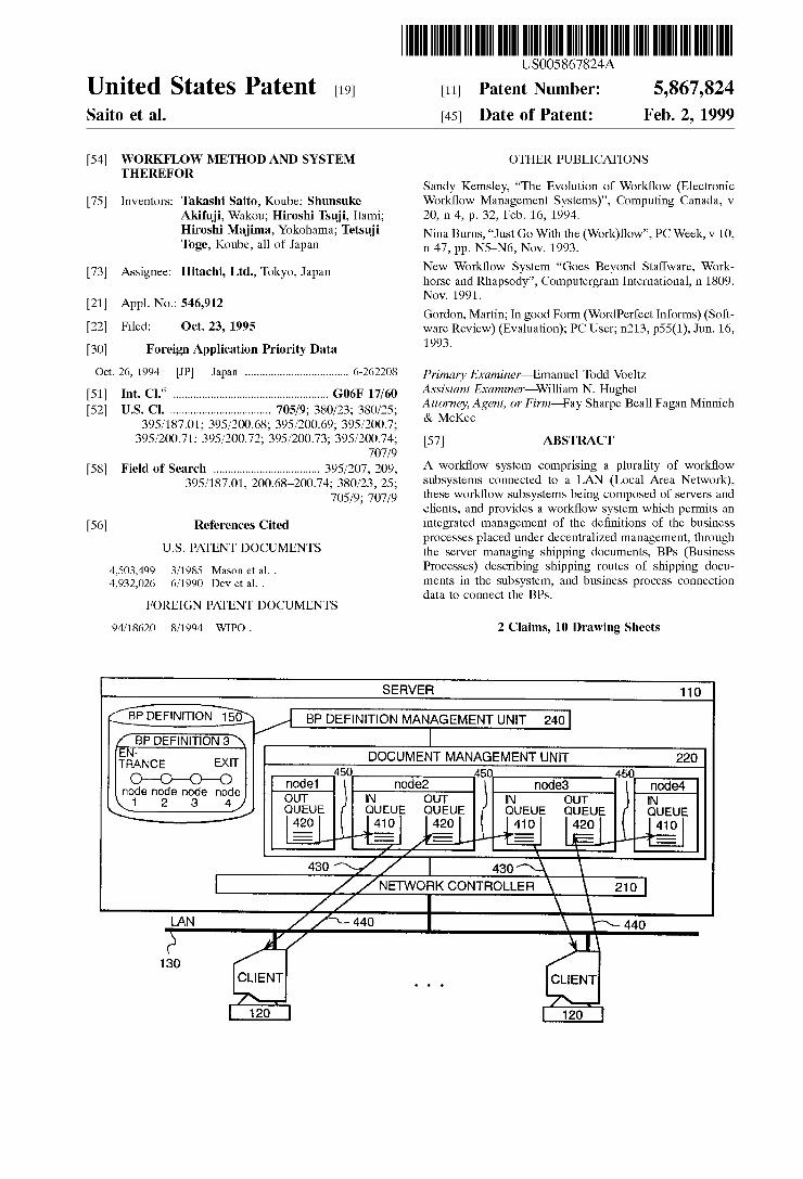
FIG. 1 is a draWing illustrating an embodiment of the con?guration of the Work?oW system according to the present invention;
FIG. 2 is a draWing illustrating an embodiment in the block diagram representing the Work?oW server according to the present invention;
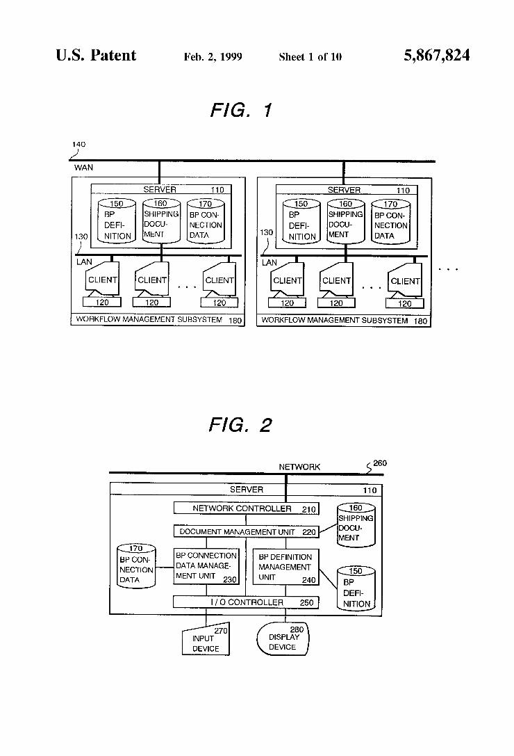
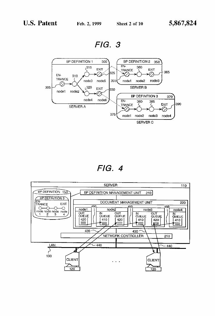
FIG. 3 is a schematic draWing representing the connection of the BP de?nition used to illustrate the present embodi ment;
FIG. 4 is a schematic draWing representing the shipping control of the shipping document used to illustrate the present embodiment;
FIG. 5 is a draWing illustrating the BP connection table as one of the BP connection data in the present embodiment;
FIG. 6 is a draWing illustrating the security table as one of the BP connection
FIG. 7 is a How chart shoWing the connection process in the present embodiment;
FIG. 8 is a draWing shoWing the shipping document data structure in the present embodiment;
FIG. 9 is a schematic draWing representing the connection of the BP de?nition used to illustrate the present embodi ment;
FIG. 10 is a draWing illustrating the BP connection table as one of the BP connection data in the present embodiment;
FIG. 11 is a draWing illustrating the BP return table as one of the BP connection
FIG. 12 is a How chart shoWing the connection process in the present embodiment;
FIG. 13 is a How chart shoWing the connection process in the present embodiment;
FIG. 14 is a draWing shoWing the shipping document data structure in the present embodiment;
FIG. 15 is a draWing shoWing the BP de?nition used to illustrate the present embodiment;
FIG. 16 is a draWing shoWing the BP de?nition used to illustrate the present embodiment;
FIG. 17 is a draWing shoWing the BP de?nition template used to illustrate the present embodiment;
15
25
35
45
55
65
4 DETAILED DESCRIPTION OF PREFERRED
EMBODIMENTS
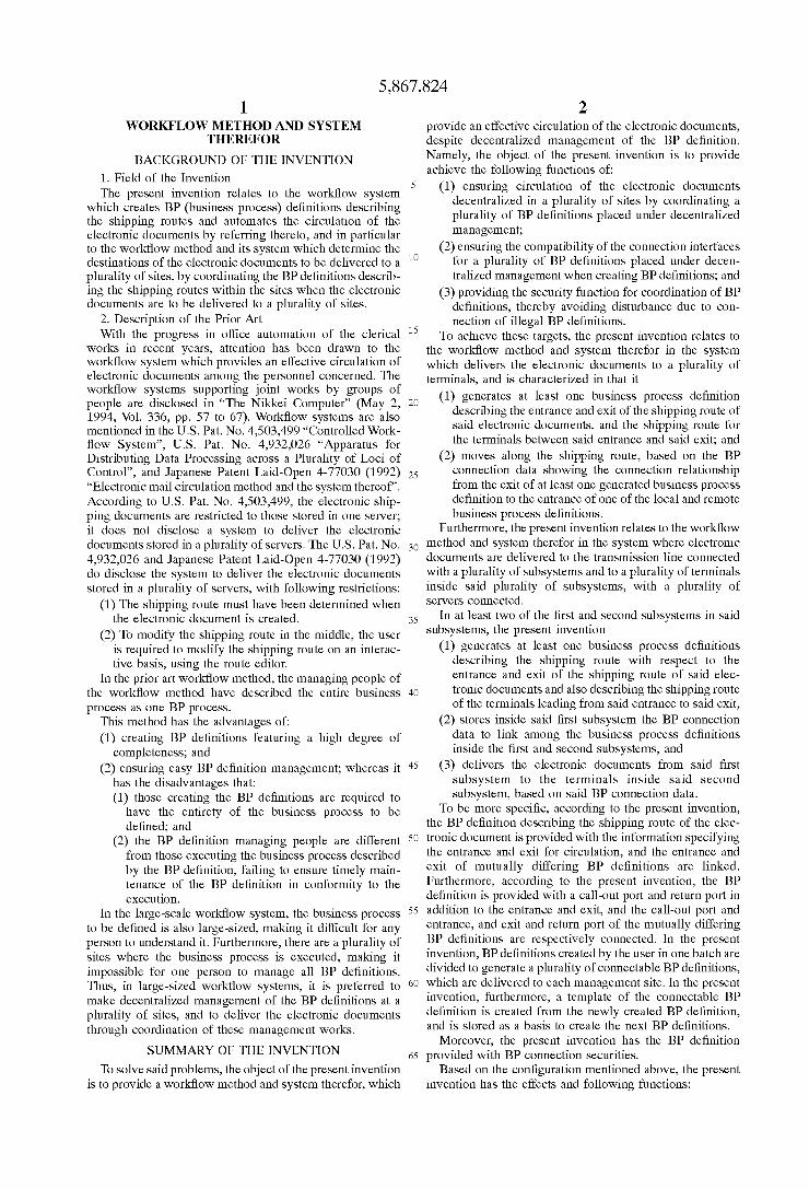
(Embodiment 1) FIG. 1 is a system con?guration draWing illustrating an
embodiment of the Work?oW system according to the present invention; In the system shoWn in the draWing, a Work?oW subsystem (180) comprising a server (110) and a plurality of clients (120) is connected to a plurality of WAN (Wide Area Network) (140). When the Work?oW subsystem is connected to the WAN as shoWn in this example, each Work?oW subsystem represents a locally decentraliZed busi ness establishment such as Tokyo Of?ce and Osaka Of?ce. When each Work?oW subsystem represents a functional
division such as Labor Section or Material Procurement Section, each Work?oW subsystem is a LAN (Local Area NetWork), not WAN. Where there are a great number of clients (120) contained in the Work?oW subsystem (180), a plurality of the servers (110) are used to decentraliZed the loads. The folloWing three types of information are managed by the server (110) included in the Work?oW subsystem (180):
(1) BP de?nition (150) describing the shipping route of the electronic document to be circulated in the Work How subsystem
(2) BP connection data (170) used to connect betWeen BP de?nitions
(3) Shipping document (160) being delivered in the Work?oW subsystem
FIG. 2 is a draWing related to the processing block constituting the server (110). The folloWing describes the server (110) processing element in the ?rst place. The netWork control unit (210) provides communications
control through the netWork betWeen the clients (120) inside a Work?oW subsystem (180) and the sever (110) of the remote Work?oW subsystem (180). In the communications With the clients (120), information on the shipping document (160) and delivery conditions of the shipping document (160) is sent to the clients (120) at the request from the clients (120). In the communications With the server (110) inside the remote Work Work?oW subsystem (180), the shipping document (160) is sent to the remote server (110) at the request from the document management unit (220). Receiving the shipping document (160) sent from the server (110) in the remote Work?oW subsystem (180), it transfers it to the document management unit (220). The document management unit (220) manages the ship
ping document (160) and the next BP location described in the BP de?nition (150) by associating them, and executes preprocessing to transmit the shipping document (160) to the remote server (110), by referring to the BP connection data (170). The BP connection data management unit (230) and the BP de?nition management unit (240) manage the BP connection data (170) created by the user and the BP de?nition (150), respectively, and execute retrieval process at the retrieval request, thereby notifying other processing units of the retrieved result. Receiving input from the user via the input device (270), the input/output control unit (250) issues processing request to the document management unit (220), the BP connection data management unit (230) or the BP de?nition management unit (240), or displays on the display device (280) the processed result obtained from the document management unit (220), the BP connection data management unit (230) or the BP de?nition management unit (240).
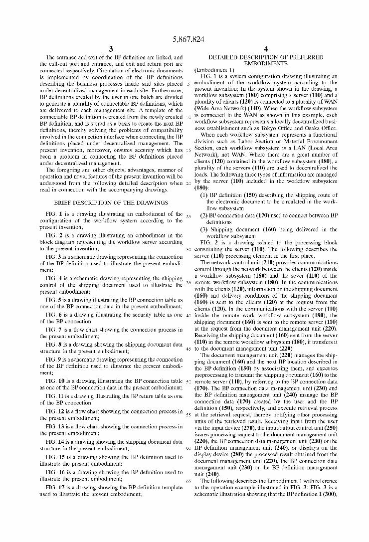
The folloWing describes the Embodiment 1 With reference to the operation example illustrated in FIG. 3: FIG. 3 is a schematic illustration shoWing that the BP de?nition 1 (300),
5,867,824 5
the BP de?nition 2 (350) and the BP de?nition 3 (370) managed independently server A, server B and server C are connected With one another. In FIG. 3, the BP de?nition (150) is described in the data How model, and the next BP location and the shipping route are described by the node and arc, respectively. One BP de?nition (150) contains the entrance node and exit node, in addition to the processing node representing one process to be treated in the Work?oW subsystem (180) to Which the BP de?nition managing server (110) pertains. The entrance node is a node to execute process of receiving the data from other BP de?nitions, While the exit node is a node to execute process of trans mitting the data to other BP de?nitions. The entrance and exit nodes are the nodes to provide compatibility With other BP de?nitions. According to the BP de?nition 1, for example, node 2 (310), node 3 (315) and node 4 (320) are processing nodes, and node 1 (305) is an entrance node, While node 5 (325) and node 6 (330) are exit nodes.
FIG. 4 is a schematic draWing representing the shipping document (160) delivery method in the Work?oW subsystem (180). The document management unit (220) is provided With the IN queue (410) and OUT queue (420) to enter the shipping documents corresponding to the processing node in the BP de?nition. The entrance node has only the OUT queue (420), While the exit node has only the IN queue (410). Those in charge of the Work on the client (120) and application pick up the shipping document (160) from the IN queue (410) corresponding to the processing node to Which they are assigned, and, after executing the process, return it to the OUT queue (420) corresponding to the processing node. Referring to the BP de?nition (150), the document management unit (220) transfers to the IN queue (410) corresponding to the next processing node the shipping document (160) in the OUT queue (420). The exit node can be linked to the entrance node of other BP de?nitions (150) by the BP connection data (170). In this case, by making reference to the BP connection data (170), the document management unit (220) transfers to the server (110) man aging the BP de?nition (150) of the next BP location the shipping document (160) of the IN queue (410) correspond ing to the exit node.
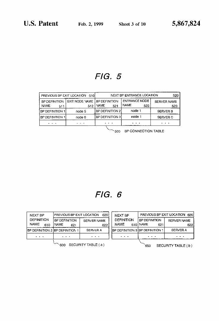
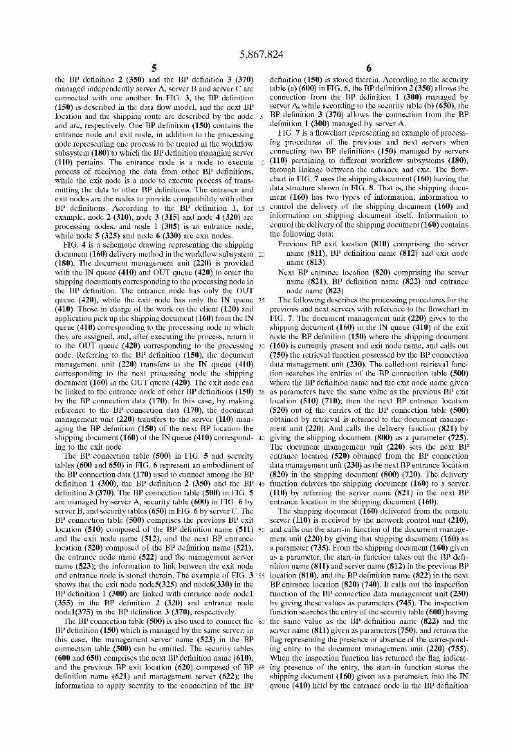
The BP connection table (500) in FIG. 5 and security tables (600 and 650) in FIG. 6 represent an embodiment of the BP connection data (170) used to connect among the BP de?nition 1 (300), the BP de?nition 2 (350) and the BP de?nition 3 (370). The BP connection table (500) in FIG. 5 are managed by server A, security table (600) in FIG. 6 by server B, and security tables (650) in FIG. 6 by server C. The BP connection table (500) comprises the previous BP exit location (510) composed of the BP de?nition name (511) and the exit node name (512), and the next BP entrance location (520) composed of the BP de?nition name (521), the entrance node name (522) and the management server name (523); the information to link betWeen the exit node and entrance node is stored therein. The example of FIG. 3 shoWs that the exit node node5(325) and node6(330) in the BP de?nition 1 (300) are linked With entrance node node1 (355) in the BP de?nition 2 (320) and entrance node node1(375) in the BP de?nition 3 (370), respectively.
The BP connection table (500) is also used to connect the BP de?nition (150) Which is managed by the same server; in this case, the management server name (523) in the BP connection table (500) can be omitted. The security tables (600 and 650) comprises the next BP de?nition name (610), and the previous BP exit location (620) composed of BP de?nition name (621) and management server (622); the information to apply security to the connection of the BP
10
15
25
35
45
55
65
6 de?nition (150) is stored therein. According to the security table (a) (600) in FIG. 6, the BP de?nition 2 (350) alloWs the connection from the BP de?nition 1 (300) managed by server A, While according to the security table (b) (650), the BP de?nition 3 (370) alloWs the connection from the BP de?nition 1 (300) managed by server A.
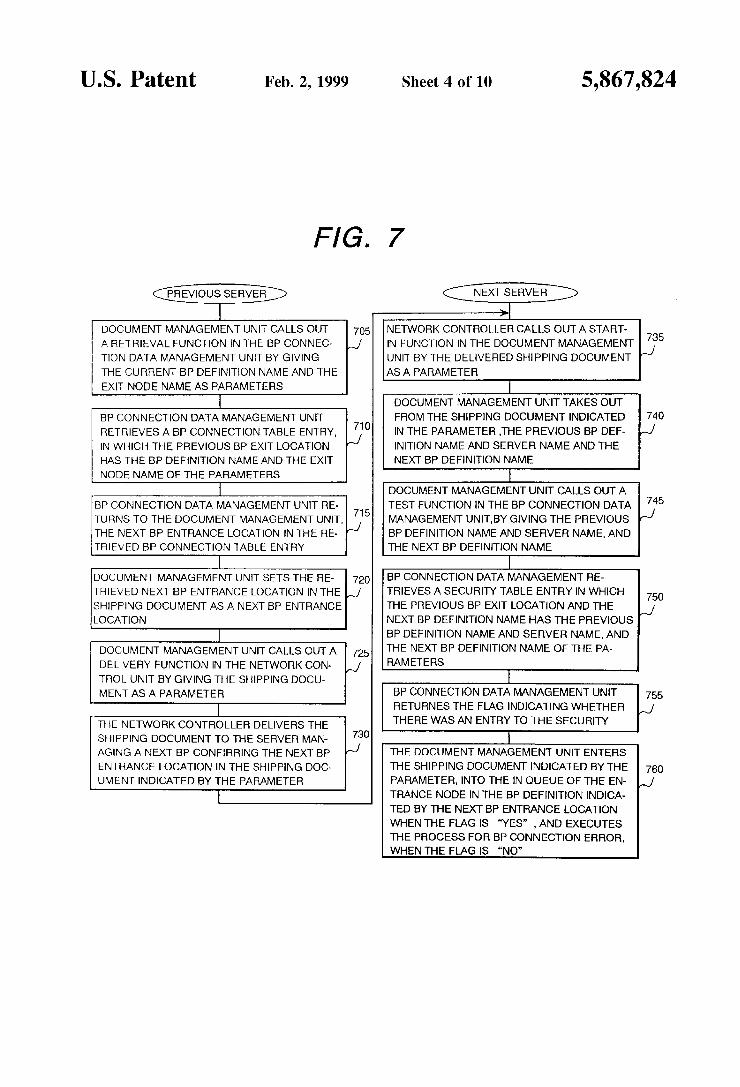
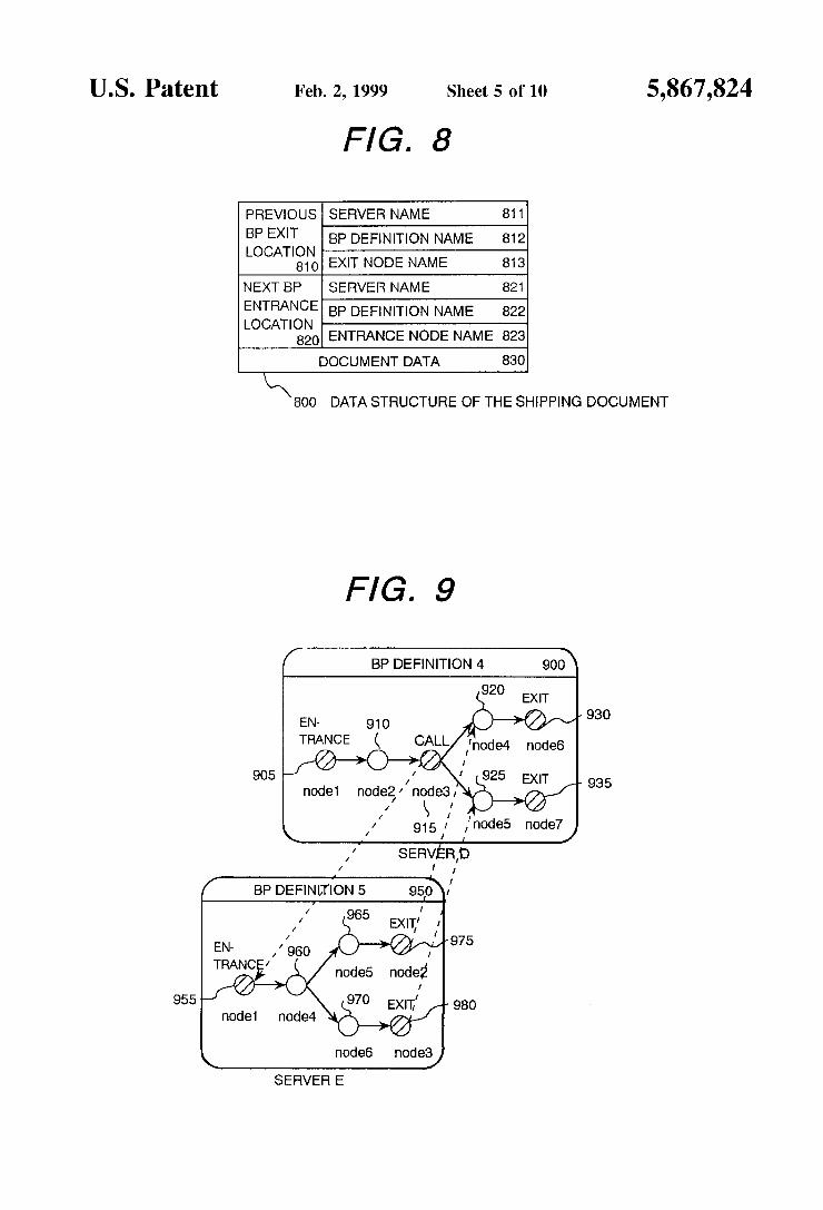
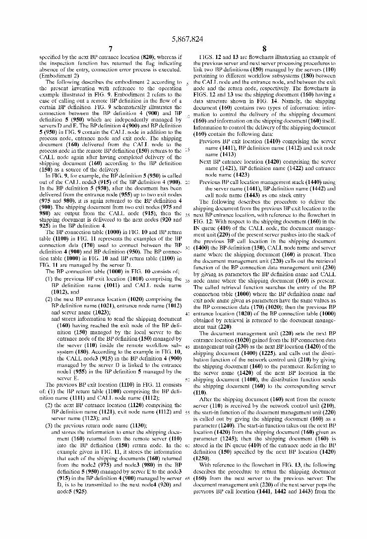
FIG. 7 is a ?oWchart representing an example of process ing procedures of the previous and next servers When connecting tWo BP de?nitions (150) managed by servers (110) pertaining to different Work?oW subsystems (180), through linkage betWeen the entrance and exit. The ?oW chart in FIG. 7 uses the shipping document (160) having the data structure shoWn in FIG. 8. That is, the shipping docu ment (160) has tWo types of information; information to control the delivery of the shipping document (160) and information on shipping document itself. Information to control the delivery of the shipping document (160) contains the folloWing data:
Previous BP exit location (810) comprising the server name (811), BP de?nition name (812) and exit node name (813)
Next BP entrance location (820) comprising the server name (821), BP de?nition name (822) and entrance node name (823)
The folloWing describes the processing procedures for the previous and next servers With reference to the ?oWchart in FIG. 7. The document management unit (220) gives to the shipping document (160) in the IN queue (410) of the exit node the BP de?nition (150) Where the shipping document (160) is currently present and exit node name, and calls out (750) the retrieval function possessed by the BP connection data management unit (230). The called-out retrieval func tion searches the entries of the BP connection table (500) Where the BP de?nition name and the exit node name given as parameters have the same value as the previous BP exit location (510) (710); then the next BP entrance location (520) out of the entries of the BP connection table (500) obtained by retrieval is returned to the document manage ment unit (220). And calls the delivery function (821) by giving the shipping document (800) as a parameter (725). The document management unit (220) sets the next BP entrance location (520) obtained from the BP connection data management unit (230) as the next BP entrance location (820) in the shipping document (800) (720). The delivery function delivers the shipping document (160) to a server (110) by referring the server name (821) in the next BP entrance location in the shipping document (160). The shipping document (160) delivered from the remote
server (110) is received by the netWork control unit (210), and calls out the start-in function of the document manage ment unit (220) by giving that shipping document (160) as a parameter (735). From the shipping document (160) given as a parameter, the start-in function takes out the BP de? nition name (811) and server name (812) in the previous BP location (810), and the BP de?nition name (822) in the next BP entrance location (820) (740). It calls out the inspection function of the BP connection data management unit (230) by giving these values as parameters (745). The inspection function searches the entry of the security table (600) having the same value as the BP de?nition name (822) and the server name (811) given as parameters (750), and returns the ?ag representing the presence or absence of the correspond ing entry to the document management unit (220) (755). When the inspection function has returned the ?ag indicat ing presence of the entry, the start-in function stores the shipping document (160) given as a parameter, into the IN queue (410) held by the entrance node in the BP de?nition
5,867,824 7
speci?ed by the next BP entrance location (820); Whereas if the inspection function has returned the ?ag indicating absence of the entry, connection error process is executed. (Embodiment 2)
The following describes the embodiment 2 according to the present invention With reference to the operation example illustrated in FIG. 9. Embodiment 2 refers to the case of calling out a remote BP de?nition in the How of a certain BP de?nition. FIG. 9 schematically illustrates the connection betWeen the BP de?nition 4 (900) and BP de?nition 5 (950) Which are independently managed by servers D and E. The BP de?nition 4 (900) and BP de?nition 5 (950) in FIG. 9 contain the CALL node in addition to the process node, entrance node and exit node. The shipping document (160) delivered from the CALL node to the process node in the remote BP de?nition (150) returns to the CALL node again after having completed delivery of the shipping document (160) according to the BP de?nition (150) as a source of the delivery.
In FIG. 9, for example, the BP de?nition 5 (950) is called out of the CALL node3 (915) of the BP de?nition 4 (900). In the BP de?nition 5 (950), after the document has been delivered from the entrance node (955) up to tWo exit nodes (975 and 980), it is again returned to the BP de?nition 4 (900). The shipping document from tWo exit nodes (975 and 980) are output from the CALL node (915); then the shipping document is delivered to the next nodes (920 and 925) in the BP de?nition 4.
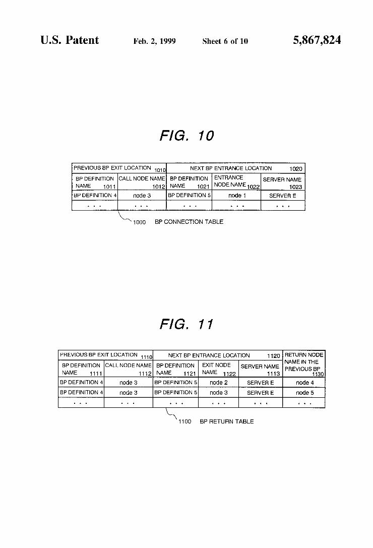
The BP connection table (1000) in FIG. 10 and BP return table (1100) in FIG. 11 represents the examples of the BP connection data (170) used to connect betWeen the BP de?nition 4 (900) and BP de?nition (950). The BP connec tion table (1000) in FIG. 10 and BP return table (1100) in FIG. 11 are managed by the server D.
The BP connection table (1000) in FIG. 10 consists of; (1) the previous BP exit location (1010) comprising the BP de?nition name (1011) and CALL node name
(1012), and (2) the next BP entrance location (1020) comprising the BP de?nition name (1021), entrance node name (1012) and server name (1023); and stores information to send the shipping document
(160) having reached the exit node of the BP de? nition (150) managed by the local server to the entrance node of the BP de?nition (150) managed by the server (110) inside the remote Work?oW sub system (180). According to the example in FIG. 10, the CALL node3 (915) in the BP de?nition 4 (900) managed by the server D is linked to the entrance node1 (955) in the BP de?nition 5 managed by the server E.
The previous BP exit location (1110) in FIG. 11 consists of: (1) the BP return table (1100) comprising the BP de? nition name (1111) and CALL node name (1112);
(2) the next BP entrance location (1120) comprising the BP de?nition name (1121), exit node name (1112) and server name (1123); and
(3) the previous return node name (1130); and stores the information to enter the shipping docu ment (160) returned from the remote server (110) into the BP de?nition (150) return node. In the example given in FIG. 11, it stores the information that each of the shipping documents (160) returned from the node2 (975) and node3 (980) in the BP de?nition 5 (950) managed by server E to the node3 (915) in the BP de?nition 4 (900) managed by server D, is to be transmitted to the next node4 (920) and node5 (925).
10
15
25
35
45
55
65
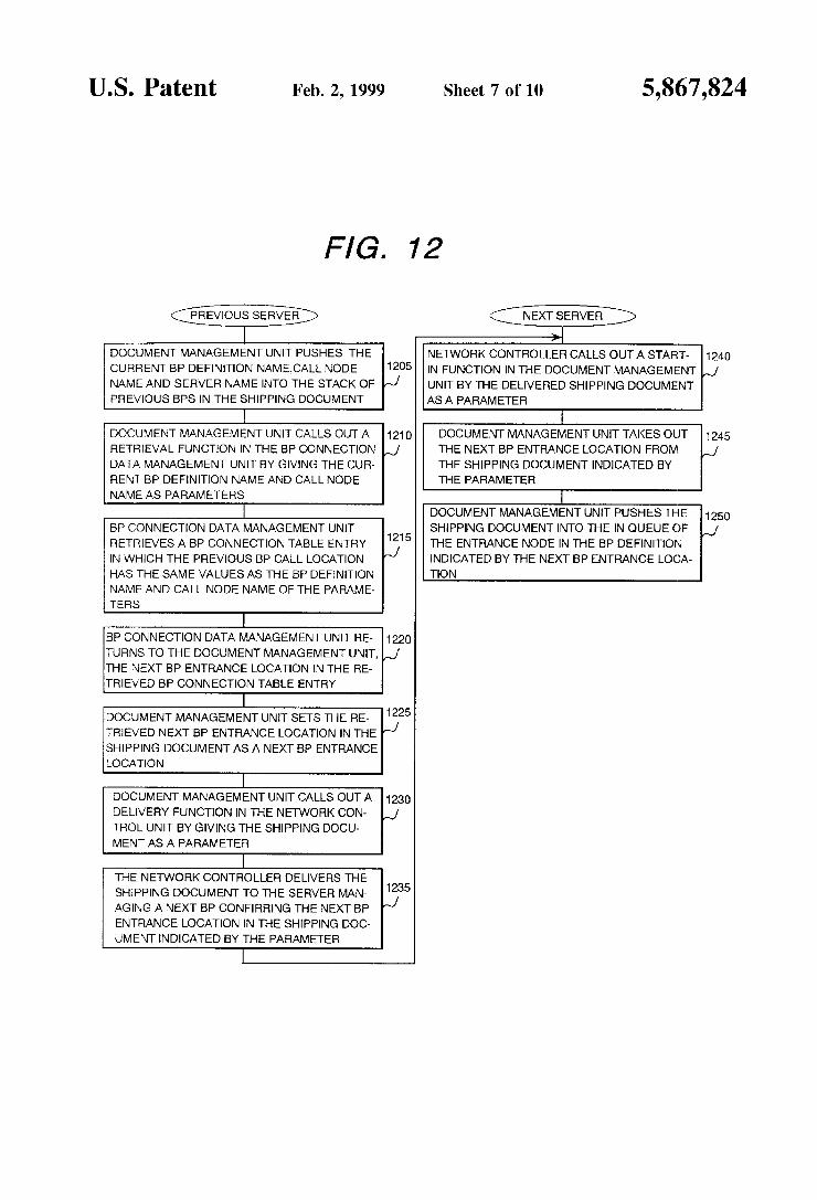
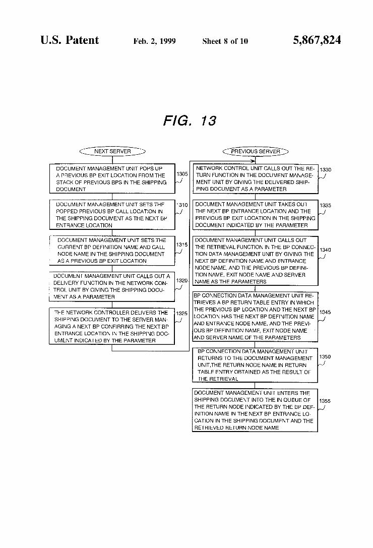
8 FIGS. 12 and 13 are ?oWcharts illustrating an example of
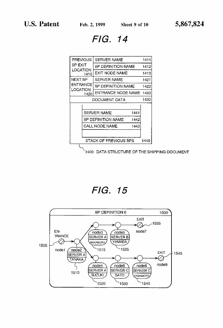
the previous server and next server processing procedures to link tWo BP de?nitions (150) managed by the servers (110) pertaining to different Work?oW subsystems (180) betWeen the CALL node and the entrance node, and betWeen the exit node and the return node, respectively. The ?oWcharts in FIGS. 12 and 13 use the shipping document (160) having a data structure shoWn in FIG. 14. Namely, the shipping document (160) contains tWo types of information: infor mation to control the delivery of the shipping document (160) and information on the shipping document (160) itself. Information to control the delivery of the shipping document (160) contain the folloWing data:
Previous BP exit location (1410) comprising the server name (1411), BP de?nition name (1412) and exit node name (1413)
Next BP entrance location (1420) comprising the server name (1421), BP de?nition name (1422) and entrance node name (1423)
Previous BP call location management stack (1440) using the server name (1441), BP de?nition name (1442) and call node name (1443) as one stack entry
The folloWing describes the procedure to deliver the shipping document from the previous BP exit location to the next BP entrance location, With reference to the ?oWchart in FIG. 12: With respect to the shipping document (160) in the IN queue (410) of the CALL node, the document manage ment unit (220) of the present server pushes into the stack of the previous BP call location in the shipping document (1400) the BP de?nition (150), CALL node name and server name Where the shipping document (160) is present. Then the document management unit (220) calls out the retrieval function of the BP connection data management unit (230) by giving as parameters the BP de?nition name and CALL node name Where the shipping document (160) is present. The called retrieval function searches the entry of the BP connection table (1000) Where the BP de?nition name and exit node name given as parameters have the same values as the BP connection data (170) (1020); then the previous BP entrance location (1020) of the BP connection table (1000) obtained by retrieval is returned to the document manage ment unit (220). The document management unit (220) sets the next BP
entrance location (1020) gained from the BP connection data management unit (230) as the next BP location (1420) of the shipping document (1400) (1225), and calls out the distri bution function of the netWork control unit (210) by giving the shipping document (160) to the parameter. Referring to the server name (1420) of the next BP location in the shipping document (1400), the distribution function sends the shipping document (160) to the corresponding server (110).
After the shipping document (160) sent from the remote server (110) is received by the netWork control unit (210), the start-in function of the document management unit (220) is called out by giving the shipping document (160) as a parameter (1240). The start-in function takes out the next BP location (1420) from the shipping document (160) given as parameter (1245); then the shipping document (160) is stored in the IN queue (410) of the entrance node in the BP de?nition (150) speci?ed by the next BP location (1420) (1250). With reference to the ?oWchart in FIG. 13, the folloWing
describes the procedure to return the shipping document (160) from the next server to the previous server: The document management unit (220) of the next server pops the previous BP call location (1441, 1442 and 1443) from the
5,867,824
stack of previous BP call location (1440) of the shipping document (1400), and set the previous BP call location as the next BP location (1420) of the shipping document (1400) (1310). Then the document management unit (220) sets as the previous BP location (1410) the BP de?nition name (159) and exit node name Where the shipping document (160) is present (1315), and calls out the distribution func tion of the netWork control unit (210) by giving the shipping document (160). Referring to the server name (1421) of the next entrance location (1420) in the shipping document (1400) given as parameter, the netWork control unit (210) delivers the shipping document (160) to the server of the next BP entrance location (1325).
The shipping document (160) delivered from the remote server (110) received by the netWork control unit (210) to call out the return function of the document management unit (220) by giving the shipping document (160) as a parameter (1330). The return function takes out the next BP entrance location (1420) and the previous BP exit location (1410) from the shipping document (160) given as a param eter (1335). They are given as parameters to call out the retrieval function of the BP connection data management unit (230) (1340). The return retrieval function searches the entry of the BP return table (1100) to Which the previous BP entrance location (1410) and the next BP exit location (1420) given as parameters are applicable (1345), thereby returning the return node name (1130) in the entry to the document management unit (220). The return function places the shipping document into the IN queue (410) of the node Which is speci?ed by the return node name (1130) returned by the return retrieval function, and Which is speci?ed by the BP de?nition name (1422) of the next BP entrance location in the shipping document (1400) (1355). Embodiment 3 When connecting the BP de?nitions created indepen
dently on a plurality of servers by a plurality of users, incompatibility problems are likely to occur to the connec tion interfaces among the BP de?nitions. Embodiments 3 and 4 illustrate hoW to provide support to adjust the con nection interfaces. When an end user has created one business process as one
BP de?nition (150) and registered it in the server (110), the server (110) divides the BP de?nition (150) to create a plurality of BP de?nitions, Which are delivered to the management server (110). The folloWing describes this procedure as Embodiment 3. Embodiment 3 shoWs the case Where the end user creates the BP de?nition (1500) shoWn in FIG. 15 and registers it into the server (110). The processing node of the BP de?nition (1500) shoWn in FIG. 15 contains the user to execute the process represented by the processing node and the name of the server for that user, in addition to the node name. The BP de?nition management unit (240) divides the processing node under BP de?nition into several groups, according to the grouping rules intro duced beloW:
If the same server is used by those executing the process in the processing node connected by an arc, their processing nodes pertain to the same group.
If different servers are used by those executing the process in the processing node connected by an arc, their processing nodes pertain to different groups.
According to the above rule, the processing node in the BP de?nition (1500) shoWn in FIG. 15 is divided into three groups; (1) 1st group comprising node2 (1510), node3 (1515) and node4 (1520),
(2) 2nd group comprising node5 (1525) alone, and (3) 3rd group comprising node6 (1530) and node8 (1540).
5
35
40
10 Next, to create one BP de?nition (150) for each group, the
BP de?nition management unit (240) provides an addition of the entry node and exit node according to the grouping rules introduced beloW:
If an arc has no initial node in a graph comprising the processing node pertaining to a group and the arcs coming in and out of that processing node, add the entrance node to the initial position of that arc.
If an arc has no terminal node in a graph comprising the processing node and the arcs coming in and out of that processing node, add the exit node to the terminal position of that arc.
FIG. 3 illustrated above shoWs three BP de?nitions Which are gained by dividing FIG. 15. Furthermore, the BP de? nition management unit (240) creates the BP connection data (170) to link betWeen the exit and entrance nodes added to connect the BP de?nition (150) obtaining by division. FIGS. 5 and 6 shoW the BP connection data (170) created by the BP de?nition management unit (240) to connect three BP de? nitions after the division shoWn in FIG. 3. Lastly, the BP de?nition (180) created by division and the BP connection data (170) to connect them are put together for each man agement server to create a system document. The system document is a special document used by the Work?oW subsystem for operation. When the BP de?nition management unit (240) gives the
system document as a parameter to call out the start-in function of the document management unit (220), the docu ment management unit (220) delivers the system document according to the setup BP de?nition. The setup BP de?nition describes shipping order of system documents, and that the setup BP de?nition is generated While the Work?oW system is operated, thereby executing the Work required for Work How system operation by delivering the system document according this de?nition. In the above example, three system documents are created; (1) a system document comprising the BP de?nition 1 (300) and BP connection table (500), (2) a system document comprising the BP de?nition 2 (350) and the security table (a) (600) and (3) a system document comprising the BP de?nition 3 (370) and the security table (b) (650). These system documents each are sent to servers A, B and C according to the setup BP de?nition. The system documents sent to the remote server (110) are delivered according to the setup BP de?nition of that server (110); ?nally, the BP de?nition (150) and the BP connection data (170) are managed by the BP connection data management unit (230) of those servers. Embodiment 4 When the end user has created the BP de?nition (150)
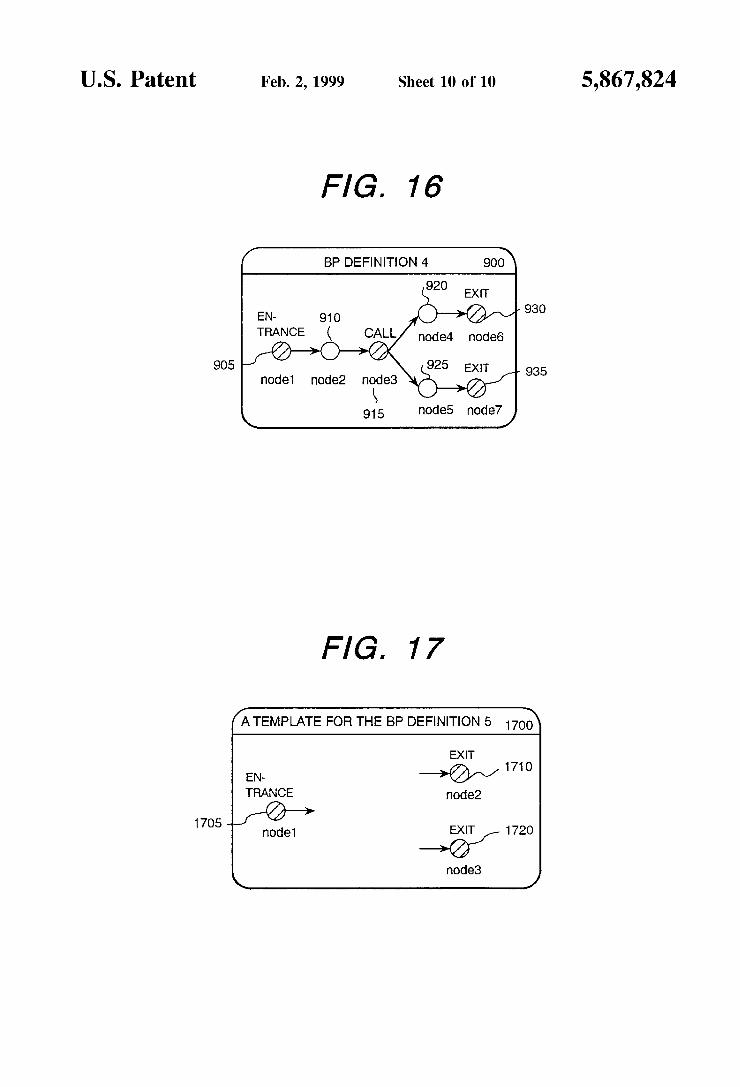
including the CALL node, and has registered it into the server (110), the server (110) creates the template of the BP de?nition to be connected, according to that BP de?nition (150), and sends it to the next management server (110). In the next server, the end user creates the BP de?nition (110) based on the delivered template of the BP de?nition. This is illustrated in the present Embodiment. Assume that the end user has created the BP de?nition 4
(900) shoWn in FIG. 16, and has registered it into the server (110). The BP de?nition 5 (900) shoWn in FIG. 16 contains a CALL node, and the BP connection table (1000) in FIG. 10 and the BP return table (1100) in FIG. 11 are set in the BP connection data (170) of this CALl node. In this case, the BP de?nition management unit (240) creates the template (1700) of the BP de?nition as illustrated in FIG. 17. the template (1700) of the BP de?nition comprises only the entrance and exit nodes linked to the CALL and return nodes. In the template (1700) of the BP de?nition, the BP
5,867,824 11
de?nition name, entrance node name and exit node name are assigned With the names speci?ed by the BP connection data (170) of FIGS. 10 and 11.
Next, the BP de?nition management unit (240) creates a system document containing the BP de?nition template (1700), and gives it as a parameter to call out the start-in function of the document management unit (220). The document management unit (220) delivers the system docu ment according to the setup BP de?nition, and sent it to the remote server (110). The remote server (110) delivers the system document according to the setup BP de?nition of that server (110). By delivering the system document, the user creates the BP de?nition (150) based on the delivered template of the BP de?nition. The created BP de?nition (150) is stored in the BP de?nition management unit (240). As discussed above, the present invention alloWs a plu
rality of decentraliZed BP de?nitions to be connected. This permits the BP de?nition describing the business process of a site to be managed independently by the site, ensuring easy modi?cation of the BP de?nition in conformity to the operating conditions. Furthermore, the present invention provides a support for the decentraliZed management of BP de?nitions. When the business processes over a plurality of sites are described, the present invention provides an auto matic compatibility of the BP de?nition connecting inter faces.
The invention claimed is: 1. A Work?oW method in a system delivering electronic
documents to a plurality of terminals in a plurality of servers With a transmission line interconnecting said servers, said method comprising:
in each of at least a ?rst server and a second server among
said plurality of servers, generating at least one busi ness process de?nition describing data How among terminals including an entrance terminal, an eXit terminal, and a shipping route of said electronic docu ments from said entrance terminal to said eXit terminal;
inside said ?rst server, storing business process connec tion data Which links the business process de?nition generated inside the ?rst server to the business process de?nition generated inside the second server;
10
15
25
35
12 inside said second server, storing connection security
information on the delivery of electronic documents from said ?rst server to said second server;
based on said stored connection security information, determining Whether said second server should accept the delivery of electronic documents from said ?rst server.
2. A Work?oW system for delivery of electronic docu ments to a plurality of terminals in a plurality of servers, the system comprising:
a transmission line connecting said servers;
in each of at least a ?rst and a second of said servers, means for generating at least one business process de?nition describing data How among the terminals including an entrance terminal, an eXit terminal, and a shipping route of the electronic documents from said entrance terminal to said eXit terminal;
a ?rst storing means for storing business process connec tion data Which links the business process de?nitions generated inside the ?rst server to another business process de?nition;
a second storing means for storing business process connection data Which links the business process de? nitions generated inside the second server to another business process de?nition;
a security information storing means for storing, inside said second server, connection security information on the delivery of electronic documents from said ?rst server to said second server;
a delivery means for delivering the electronic documents from said ?rst server to the terminals inside said second server, based on said business process connection data stored inside said ?rst server; and,
a means Which uses said stored connection security infor mation for determining Whether said second server accepts the delivery of electronic documents from said ?rst server.