Embed Size (px)
DESCRIPTION
tools required for wood work
Citation preview
are
CHAPTER 3
WOODWORKING TOOLS, MATERIALS, ANDMETHODS
As a Builder, hand and power woodworking toolsessential parts of your trade. To be a proficient
woodworking craftsman, you must be able to use andmaintain a large variety of field and shop toolseffectively. To perform your work quickly,accurately, and safely, you must select and use thecorrect tool for the job at hand. Without the propertools and the knowledge to use them, you waste time,reduce efficiency, and may injure yourself or others.
Power tools not only are essential in performingspecific jobs, but also play an important role in yourdaily work activities. Keep in mind that you areresponsible for knowing and observing all safetyprecautions applicable to the tools and equipment youoperate. For additional information on the topicsdiscussed in this chapter, you are encouraged to studyTools and Their Uses, NAVEDTRA 10085-B2.Because that publication contains a detaileddiscussion of common tools used by Builders, we willnot repeat that information in this chapter.
In this chapter, several of the most commonpower tools used by Builders are briefly described.Their uses, general characteristics, attachments, andsafety and operating features are outlined. To becomeskilled with these power tools and hand tools, youmust use them. You should also study themanufacturer’s operator and maintenance guides foreach tool you use for additional guidance. We willalso be covering materials and methods ofwoodworking.
POWER TOOLS
LEARNING OBJECTIVE: Upon completingthis section, you should be able to determinethe proper use and maintenance requirementsof portable power tools.
Your duties as a Builder include developing andimproving your skills and techniques when workingwith different power tools. In this section, we’llidentify and discuss the most common power toolsthat are in the Builder’s workshop or used on thejobsite. We’ll also discuss safety precautions as they
relate to the particular power tool under discussion.You must keep in mind and continually stress to yourcrew that woodworking power tools can bedangerous, and that safety is everyone’s responsi-bility.
SHOP TOOLS
As a Builder, you might be assigned to a shop.Therefore, you will need to know some of thecommon power tools and equipment found there.
Shop Radial Arm Saw
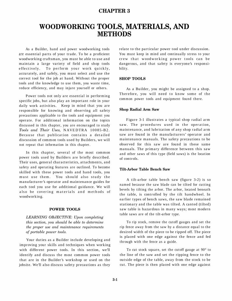
Figure 3-1 illustrates a typical shop radial armsaw. The procedures used in the operation,maintenance, and lubrication of any shop radial armsaw are found in the manufacturers’ operator andmaintenance manuals. The safety precautions to beobserved for this saw are found in these samemanuals. The primary difference between this sawand other saws of this type (field saws) is the locationof controls.
Tilt-Arbor Table Bench Saw
A tilt-arbor table bench saw (figure 3-2) is sonamed because the saw blade can be tilted for cuttingbevels by tilting the arbor. The arbor, located beneaththe table, is controlled by the tilt handwheel. Inearlier types of bench saws, the saw blade remainedstationary and the table was tilted. A canted (tilted)saw table is hazardous in many ways; most moderntable saws are of the tilt-arbor type.
To rip stock, remove the cutoff gauges and set therip fence away from the saw by a distance equal to thedesired width of the piece to be ripped off. The pieceis placed with one edge against the fence and fedthrough with the fence as a guide.
To cut stock square, set the cutoff gauge at 90° tothe line of the saw and set the ripping fence to theoutside edge of the table, away from the stock to becut. The piece is then placed with one edge against
3-1
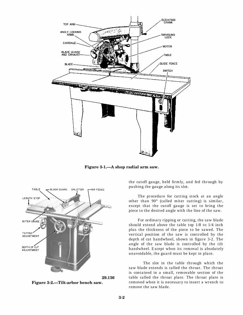
Figure 3-1.—A shop radial arm saw.
29.136Figure 3-2.—Tilt-arbor bench saw.
the cutoff gauge, held firmly, and fed through bypushing the gauge along its slot.
The procedure for cutting stock at an angleother than 90° (called miter cutting) is similar,except that the cutoff gauge is set to bring thepiece to the desired angle with the line of the saw.
For ordinary ripping or cutting, the saw bladeshould extend above the table top 1/8 to 1/4 inchplus the thickness of the piece to be sawed. Thevertical position of the saw is controlled by thedepth of cut handwheel, shown in figure 3-2. Theangle of the saw blade is controlled by the tilthandwheel. Except when its removal is absolutelyunavoidable, the guard must be kept in place.
The slot in the table through which thesaw blade extends is called the throat. The throatis contained in a small, removable section of thetable called the throat plate. The throat plate isremoved when it is necessary to insert a wrench toremove the saw blade.
3-2
The blade is held on the arbor by the arbor nut. A sawis usually equipped with several throat plates,containing throats of various widths. A wider throat isrequired when a dado head is used on the saw. A dadohead consists of two outside grooving saws (whichare much like combination saws) and as manyintermediate chisel-type cutters (called chippers) asare required to make up the designated width of thegroove or dado. Grooving saws are usually I/S-inchthick; consequently, one grooving saw will cut a1/8-inch groove, and the two, used together, will cut a1/4-inch groove. Intermediate cutters come invarious thicknesses.
Observe the following safety precautions whenoperating the tilt-arbor table bench saw:
Do not use a ripsaw blade for crosscutting or acrosscut saw blade for ripping. When rippingand crosscutting frequently, you should installa combination blade to eliminate constantlychanging the blade. Make sure the saw blade issharp, unbroken, and free from cracks beforeusing. The blade should be changed if itbecomes dull, cracked, chipped, or warped.
Be sure the saw blade is set at proper heightabove the table to cut through the wood.
Avoid the hazard of being hit by materialscaused by kickbacks by standing to one side ofthe saw.
Always use a push stick to push short, narrowpieces between the saw blade and the gauge.
Keep stock and scraps from accumulating onthe saw table and in the immediate workingarea.
Never reach over the saw to obtain materialfrom the other side.
When cutting, do not feed wood into the sawblade faster than it will cut freely and cleanly.
Never leave the saw unattended with the poweron.
Band Saw
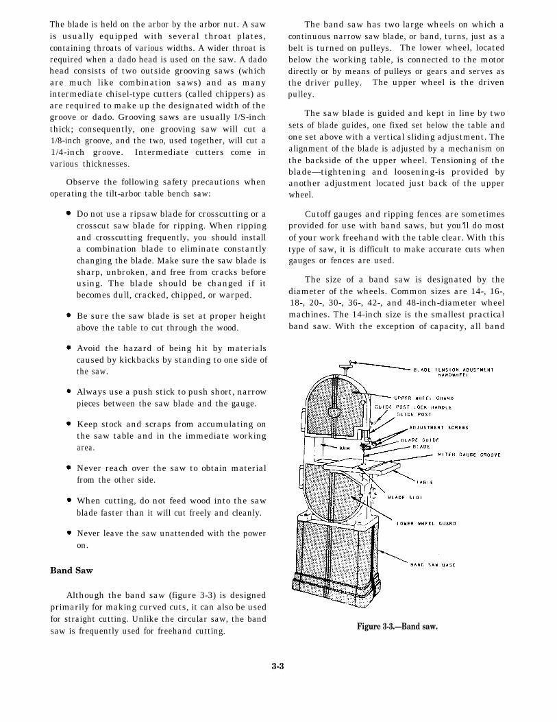
Although the band saw (figure 3-3) is designedprimarily for making curved cuts, it can also be usedfor straight cutting. Unlike the circular saw, the bandsaw is frequently used for freehand cutting.
3-3
The band saw has two large wheels on which acontinuous narrow saw blade, or band, turns, just as abelt is turned on pulleys. The lower wheel, locatedbelow the working table, is connected to the motordirectly or by means of pulleys or gears and serves asthe driver pulley. The upper wheel is the drivenpulley.
The saw blade is guided and kept in line by twosets of blade guides, one fixed set below the table andone set above with a vertical sliding adjustment. Thealignment of the blade is adjusted by a mechanism onthe backside of the upper wheel. Tensioning of theblade—tightening and loosening-is provided byanother adjustment located just back of the upperwheel.
Cutoff gauges and ripping fences are sometimesprovided for use with band saws, but you’ll do mostof your work freehand with the table clear. With thistype of saw, it is difficult to make accurate cuts whengauges or fences are used.
The size of a band saw is designated by thediameter of the wheels. Common sizes are 14-, 16-,18-, 20-, 30-, 36-, 42-, and 48-inch-diameter wheelmachines. The 14-inch size is the smallest practicalband saw. With the exception of capacity, all band
Figure 3-3.—Band saw.
saws are much the same with regard to maintenance,operation, and adjustment.
A rule of thumb used by many Seabees is that thewidth of the blade should be one-eighth the minimumradius to be cut. Therefore, if the piece on hand has a4-inch radius, the operator should select a 1/2-inchblade. Don’t construe this to mean that the minimumradius that can be cut is eight times the width of theblade; rather, the ratio indicates the practical limit forhigh-speed band saw work.
Blades, or bands, for band saws are designated bypoints (tooth points per inch), thickness (gauge), andwidth. The required length of a blade is found byadding the circumference of one wheel to twice thedistance between the wheel centers. Length can varywithin a limit of twice the tension adjustment range.
Band saw teeth are shaped like the teeth in a handripsaw blade, which means that their fronts are filed at90° to the line of the saw. Reconditioning proceduresare the same as those for a hand ripsaw, except thatvery narrow band saws with very small teeth mustusually be set and sharpened by special machines.
Observe the following safety precautions whenoperating a band saw:
Keep your fingers away from the movingblade.
Keep the table clear of stock and scraps so yourwork will not catch as you push it along.
Keep the upper guide just above the work, notexcessively high.
Don’t use cracked blades. If a blade developsa click as it passes through the work, theoperator should shut off the power because theclick is a danger signal that the blade is crackedand may be ready to break. After the saw bladehas stopped moving, it should be replaced withone in proper condition.
If the saw blade breaks, the operator shouldshut off the power immediately and not attemptto remove any part of the saw blade until themachine is completely stopped.
If the work binds or pinches on the blade, theoperator should never attempt to back the workaway from the blade while the saw is in motionsince this may break the blade. The operatorshould always see that the blade is workingfreely through the cut.
A band saw should not be operated in alocation where the temperature is below 45°F.The blade may break from the coldness.
Using a small saw blade for large work orforcing a wide saw on a small radius is badpractice. The saw blade should, in all cases, beas wide as the nature of the work will permit.
Band saws should not be stopped by thrusting apiece of wood against the cutting edge or sideof the band saw blade immediately after thepower has been shut off; doing so may causethe blade to break. Band saws with36-inch-wheel diameters and larger shouldhave a hand or foot brake.
Particular care should be taken whensharpening or brazing a band saw blade toensure the blade is not overheated and thebrazed joints are thoroughly united andfinished to the same thickness as the rest of theblade. It is recommended that all band sawblades be butt welded where possible; thismethod is much superior to the old style ofbrazing.
Drill Press
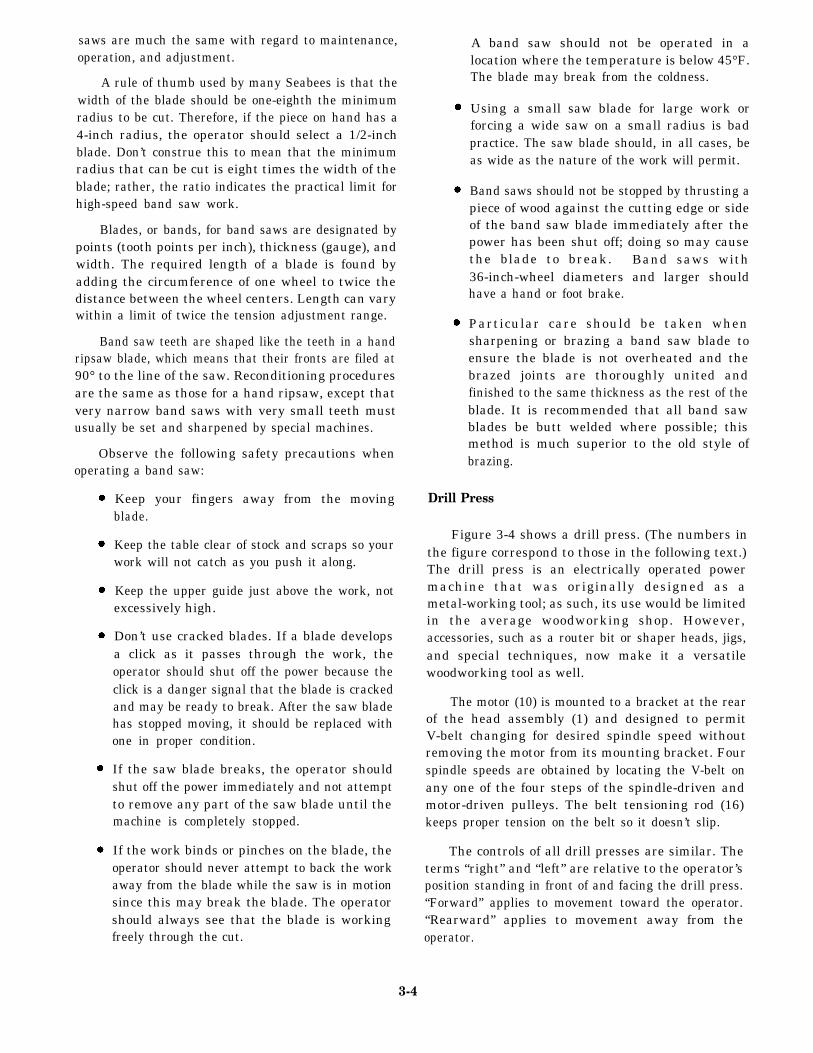
Figure 3-4 shows a drill press. (The numbers inthe figure correspond to those in the following text.)The drill press is an electrically operated powermachine that was originally designed as ametal-working tool; as such, its use would be limitedin the average woodworking shop. However,accessories, such as a router bit or shaper heads, jigs,and special techniques, now make it a versatilewoodworking tool as well.
The motor (10) is mounted to a bracket at the rearof the head assembly (1) and designed to permitV-belt changing for desired spindle speed withoutremoving the motor from its mounting bracket. Fourspindle speeds are obtained by locating the V-belt onany one of the four steps of the spindle-driven andmotor-driven pulleys. The belt tensioning rod (16)keeps proper tension on the belt so it doesn’t slip.
The controls of all drill presses are similar. Theterms “right” and “left” are relative to the operator’sposition standing in front of and facing the drill press.“Forward” applies to movement toward the operator.“Rearward” applies to movement away from theoperator.
3-4
The on/off switch (11) is located in the front ofthe drill press for easy access.
The spindle and quill feed handles (2) radiatefrom the spindle and quill pinion feed (3) hub, whichis located on the lower right-front side of the headassembly (1). Pulling forward and down on any oneof the three spindle and quill feed handles, whichpoint upward at the time, moves the spindle and quillassembly downward. Release the feed handle (2) andthe spindle and quill assembly return to the retractedor upper position by spring action.
The quill lock handle (4) is located at the lowerleft-front side of the head assembly. Turn the quilllock handle clockwise to lock the quill at a desiredoperating position. Release the quill by turning thequill lock handle counterclockwise. However, in
most cases, the quill lock handle will be in thereleased position.
The head lock handle (5) is located at the left-rearside of the head assembly. Turn the head leek handleclockwise to lock the head assembly at a desiredvertical height on the bench column. Turn the headlock handle counterclockwise to release the headassembly. When operating the drill press, you mustensure that the head lock handle is tight at all times.
The head support collar handle (6) is located atthe right side of the head support collar and below thehead assembly. The handle locks the head supportcollar, which secures the head vertically on the benchcolumn, and prevents the head from dropping whenthe head lock handle is released. Turn the headsupport collar lock handle clockwise to lock thesupport to the bench column and counterclockwise to
Figure 3-4.—Drill press.
3-5
release the support. When operating the drill press,ensure that the head support collar lock handle is tightat all times.
As you face the drill press, the tilting table lockhandle is located at the right-rear side of the tiltingtable bracket. The lockpin secures the table at ahorizontal or 45° angle. This allows you to move thetable to the side, out of the way for long pieces ofwood. The table support collar (8) allows you to raiseor lower the table. Turn the tilting table lock handlecounterclockwise to release the tilting table bracket soit can be moved up and down or around the benchcolumn. Lock the tilting table assembly at the desiredheight by turning the lock handle clockwise. Whenoperating the drill press, ensure that the tilting tablelock handle is tight at all times.
The adjustable locknut (14) is located on thedepth gauge rod (17). The purpose of the adjustablelocknut is to regulate depth drilling. Turn theadjustable locknut clockwise to decrease thedownward travel of the spindle. The locknut must besecured against the depth pointer (13) when operatingthe drill press. The depth of the hole is shown on thedepth scale (15).
Observe the following safety precautions whenoperating a drill press:
Make sure that the drill is properly secured inthe chuck (12) and that the chuck key (9) isremoved before starting the drill press.
Make sure your material is properly secured.
Operate the feed handle with a slow, steadypressure to make sure you don’t break the drillbit or cause the V-belt to slip.
Make sure all locking handles are tight and thatthe V-belt is not slipping.
Make sure the electric cord is securelyconnected and in good shape.
Make sure you are not wearing hanging orloose clothing.
Listen for any sounds that may betrouble.
After you have finished operatingpress, make sure the area is clean.
signs of
the drill
Woodworking Lathe
The woodworking lathe is, without question, theoldest of all woodworking machines. In its earlyform, it consisted of two holding centers with thesuspended stock being rotated by an endless rope belt.It was operated by having one person pull on the ropehand over hand while the cutting was done by asecond person holding crude hand lathe tools on animprovised beam rest.
The actual operations of woodturning performedon a modern lathe are still done to a great degree withwoodturner’s hand tools. However, machine lathework is coming more and more into use with theintroduction of newly designed lathes for thatpurpose.
The lathe is used in turning or shaping rounddrums, disks, and any object that requires a truediameter. The size of a lathe is determined by themaximum diameter of the work it can swing over itsbed. There are various sizes and types of wood lathes,ranging from very small sizes for delicate work tolarge surface or bull lathes that can swing jobs 15 feetin diameter.
Figure 3-5 illustrates a type of lathe that you mayfind in your shop. It is made in three sizes to swing16-, 20-, and 24-inch diameter stock. The lathe hasfour major parts: bed, headstock, tailstock, and toolrest.
The lathe shown in figure 3-5 has an iron bed andcomes in assorted lengths. The bed is a broad, flatsurface that supports the other parts of the machine.
The headstock is mounted on the left end of thelathe bed. All power for the lathe is transmittedthrough the headstock. It has a fully enclosed motorthat gives variable spindle speed. The spindle isthreaded at the front end to receive the faceplates. Afaceplate attachment to the motor spindle is furnishedto hold or mount small jobs having large diameters.There is also a flange on the rear end of the spindle toreceive large faceplates, which are held securely byfour stud bolts.
The tailstock is located on the right end of thelathe and is movable along the length of the bed. Itsupports one end of the work while the other end isbeing turned by the headstock spur. The tail centercan be removed from the stock by simply backing thescrew. The shank is tapered to center the pointautomatically.
3-6
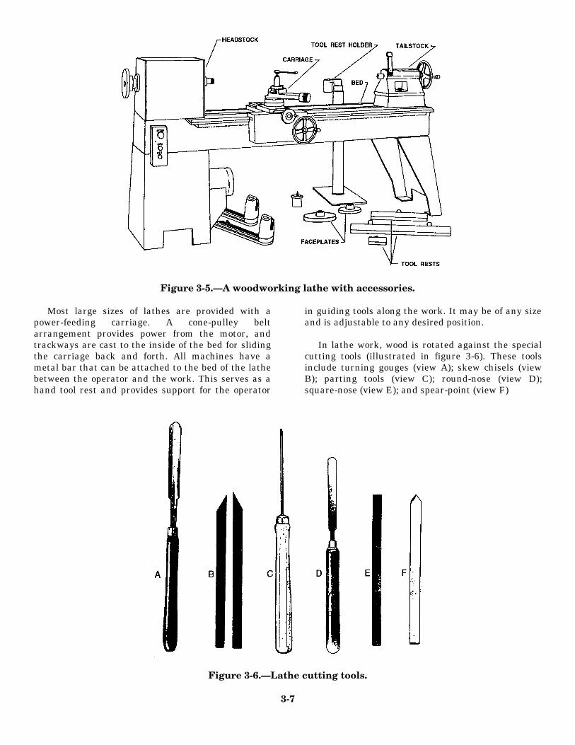
Figure 3-5.—A woodworking lathe with accessories.
Most large sizes of lathes are provided with apower-feeding carriage. A cone-pulley beltarrangement provides power from the motor, andtrackways are cast to the inside of the bed for slidingthe carriage back and forth. All machines have ametal bar that can be attached to the bed of the lathebetween the operator and the work. This serves as ahand tool rest and provides support for the operator
in guiding tools along the work. It may be of any sizeand is adjustable to any desired position.
In lathe work, wood is rotated against the specialcutting tools (illustrated in figure 3-6). These toolsinclude turning gouges (view A); skew chisels (viewB); parting tools (view C); round-nose (view D);square-nose (view E); and spear-point (view F)
Figure 3-6.—Lathe cutting tools.
3-7
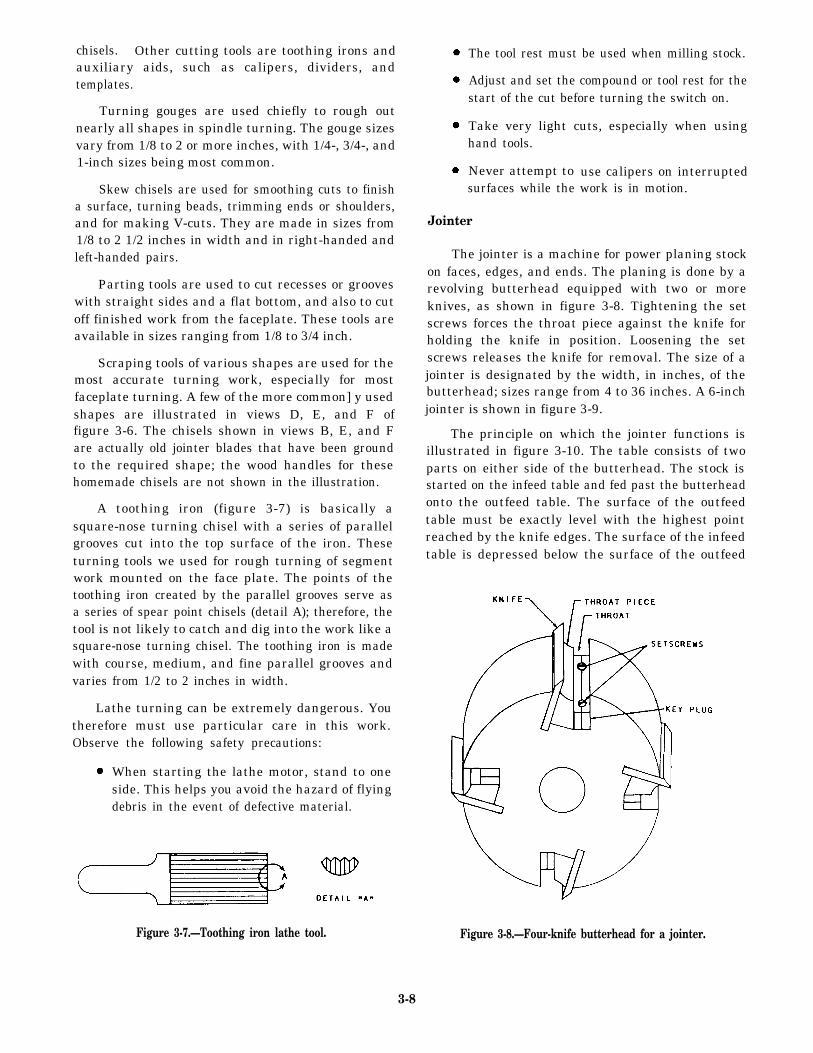
chisels. Other cutting tools are toothing irons andauxiliary aids, such as calipers, dividers, andtemplates.
Turning gouges are used chiefly to rough outnearly all shapes in spindle turning. The gouge sizesvary from 1/8 to 2 or more inches, with 1/4-, 3/4-, and1-inch sizes being most common.
Skew chisels are used for smoothing cuts to finisha surface, turning beads, trimming ends or shoulders,and for making V-cuts. They are made in sizes from1/8 to 2 1/2 inches in width and in right-handed andleft-handed pairs.
Parting tools are used to cut recesses or grooveswith straight sides and a flat bottom, and also to cutoff finished work from the faceplate. These tools areavailable in sizes ranging from 1/8 to 3/4 inch.
Scraping tools of various shapes are used for themost accurate turning work, especially for mostfaceplate turning. A few of the more common] y usedshapes are illustrated in views D, E, and F offigure 3-6. The chisels shown in views B, E, and Fare actually old jointer blades that have been groundto the required shape; the wood handles for thesehomemade chisels are not shown in the illustration.
A toothing iron (figure 3-7) is basically asquare-nose turning chisel with a series of parallelgrooves cut into the top surface of the iron. Theseturning tools we used for rough turning of segmentwork mounted on the face plate. The points of thetoothing iron created by the parallel grooves serve asa series of spear point chisels (detail A); therefore, thetool is not likely to catch and dig into the work like asquare-nose turning chisel. The toothing iron is madewith course, medium, and fine parallel grooves andvaries from 1/2 to 2 inches in width.
Lathe turning can be extremely dangerous. Youtherefore must use particular care in this work.Observe the following safety precautions:
When starting the lathe motor, stand to oneside. This helps you avoid the hazard of flyingdebris in the event of defective material.
Figure 3-7.—Toothing iron lathe tool.
The tool rest must be used when milling stock.
Adjust and set the compound or tool rest for thestart of the cut before turning the switch on.
Take very light cuts, especially when usinghand tools.
Never attempt tosurfaces while the
Jointer
use calipers on interruptedwork is in motion.
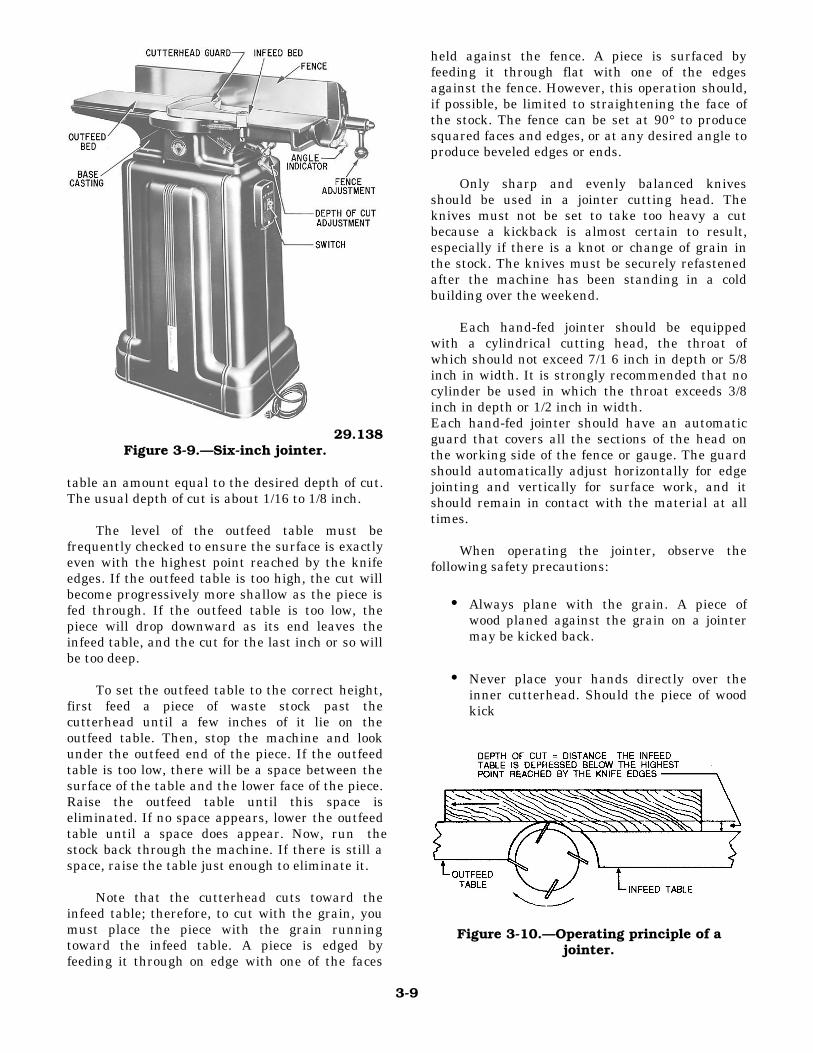
The jointer is a machine for power planing stockon faces, edges, and ends. The planing is done by arevolving butterhead equipped with two or moreknives, as shown in figure 3-8. Tightening the setscrews forces the throat piece against the knife forholding the knife in position. Loosening the setscrews releases the knife for removal. The size of ajointer is designated by the width, in inches, of thebutterhead; sizes range from 4 to 36 inches. A 6-inchjointer is shown in figure 3-9.
The principle on which the jointer functions isillustrated in figure 3-10. The table consists of twoparts on either side of the butterhead. The stock isstarted on the infeed table and fed past the butterheadonto the outfeed table. The surface of the outfeedtable must be exactly level with the highest pointreached by the knife edges. The surface of the infeedtable is depressed below the surface of the outfeed
Figure 3-8.—Four-knife butterhead for a jointer.
3-8
29.138Figure 3-9.—Six-inch jointer.
table an amount equal to the desired depth of cut.The usual depth of cut is about 1/16 to 1/8 inch.
The level of the outfeed table must befrequently checked to ensure the surface is exactlyeven with the highest point reached by the knifeedges. If the outfeed table is too high, the cut willbecome progressively more shallow as the piece isfed through. If the outfeed table is too low, thepiece will drop downward as its end leaves theinfeed table, and the cut for the last inch or so willbe too deep.
To set the outfeed table to the correct height,first feed a piece of waste stock past thecutterhead until a few inches of it lie on theoutfeed table. Then, stop the machine and lookunder the outfeed end of the piece. If the outfeedtable is too low, there will be a space between thesurface of the table and the lower face of the piece.Raise the outfeed table until this space iseliminated. If no space appears, lower the outfeedtable until a space does appear. Now, run thestock back through the machine. If there is still aspace, raise the table just enough to eliminate it.
Note that the cutterhead cuts toward theinfeed table; therefore, to cut with the grain, youmust place the piece with the grain runningtoward the infeed table. A piece is edged byfeeding it through on edge with one of the faces
held against the fence. A piece is surfaced byfeeding it through flat with one of the edgesagainst the fence. However, this operation should,if possible, be limited to straightening the face ofthe stock. The fence can be set at 90° to producesquared faces and edges, or at any desired angle toproduce beveled edges or ends.
Only sharp and evenly balanced knivesshould be used in a jointer cutting head. Theknives must not be set to take too heavy a cutbecause a kickback is almost certain to result,especially if there is a knot or change of grain inthe stock. The knives must be securely refastenedafter the machine has been standing in a coldbuilding over the weekend.
Each hand-fed jointer should be equippedwith a cylindrical cutting head, the throat ofwhich should not exceed 7/1 6 inch in depth or 5/8inch in width. It is strongly recommended that nocylinder be used in which the throat exceeds 3/8inch in depth or 1/2 inch in width.Each hand-fed jointer should have an automaticguard that covers all the sections of the head onthe working side of the fence or gauge. The guardshould automatically adjust horizontally for edgejointing and vertically for surface work, and itshould remain in contact with the material at alltimes.
When operating the jointer, observe thefollowing safety precautions:
• Always plane with the grain. A piece ofwood planed against the grain on a jointermay be kicked back.
• Never place your hands directly over the
inner cutterhead. Should the piece of woodkick
Figure 3-10.—Operating principle of ajointer.
3-9
back, your hands will drop on the blades. Startwith your hands on the infeed bed. When the pieceof wood is halfway through, reach around withyour left hand and steady the piece of wood on theoutfeed bed. Finish with both your hands on theoutfeed bed.
• Never feed a piece of wood with your thumbor finger against the end of the piece ofwood being fed into the jointer. Keep yourhands on top of the wood at all times.
• Avoid jointing short pieces of wood
whenever possible. Joint a longer piece ofwood and then cut it to the desired size. Ifyou must joint a piece of wood shorter than18 inches, use a push stick to feed it throughthe jointer.
• Never use a jointer with dull cutter blades.
Dull blades have a tendency to kick thepiece, and a kickback is always dangerous.
• Keep the jointer table and the floor around
the jointer clear of scraps, chips, andshavings. Always stop the jointer beforebrushing off and cleaning up those scraps,chips, and shavings.
• Never joint a piece of wood that containsloose knots.
• Keep your eyes and undivided attention on
the jointer as you are working. Do not talkto anyone while operating the jointer.
Remember, the jointer is one of the mostdangerous machines in the woodworking shop.Only experienced and responsible personnelshould be allowed to operate it using the basicsafety precautions provided above.
Surfacer
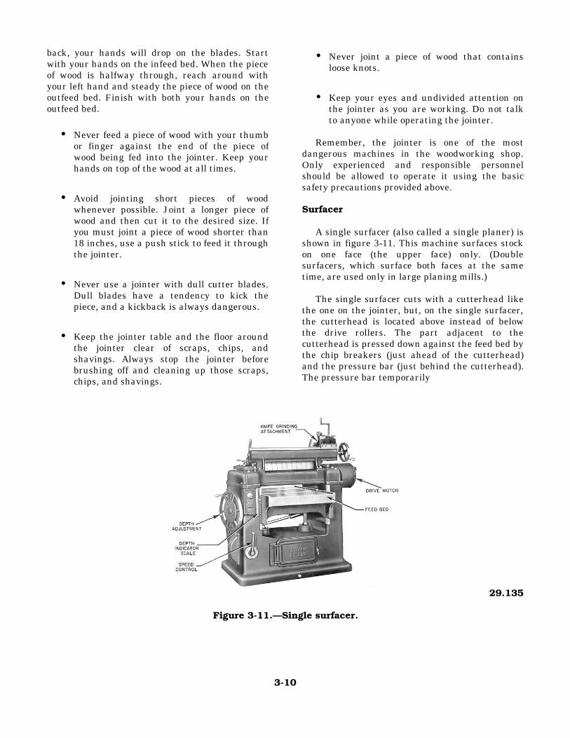
A single surfacer (also called a single planer) isshown in figure 3-11. This machine surfaces stockon one face (the upper face) only. (Doublesurfacers, which surface both faces at the sametime, are used only in large planing mills.)
The single surfacer cuts with a cutterhead likethe one on the jointer, but, on the single surfacer,the cutterhead is located above instead of belowthe drive rollers. The part adjacent to thecutterhead is pressed down against the feed bed bythe chip breakers (just ahead of the cutterhead)and the pressure bar (just behind the cutterhead).The pressure bar temporarily
29.135
Figure 3-11.—Single surfacer.
3-10
straightens out any warp a piece may have; a piecethat goes into the surfacer warped will come out stillwarped. This is not a defect in the machine; thesurfacer is designed for surfacing only, not for truingwarped stock. If true plane surfaces are desired, oneface of the stock (the face that goes down in thesurfacer) must be trued on the jointer before the pieceis feed through the surfacer. If the face that goesdown in the surfacer is true, the surfacer will planethe other face true.
Observe the following safety precautions whenoperating a surfacer:
• The cutting head should be covered by metalguards.
• Feed rolls should be guarded by a hood or asemicylindrical guard.
• Never force wood through the machine. • If a piece of wood gets stuck, turn off the
surfacer and lower the feed bed.
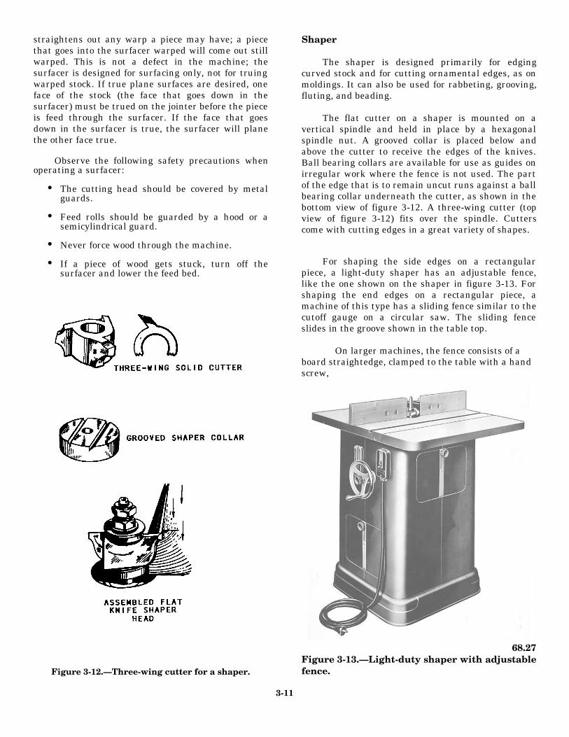
Figure 3-12.—Three-wing cutter for a shaper.
Shaper
The shaper is designed primarily for edgingcurved stock and for cutting ornamental edges, as onmoldings. It can also be used for rabbeting, grooving,fluting, and beading.
The flat cutter on a shaper is mounted on avertical spindle and held in place by a hexagonalspindle nut. A grooved collar is placed below andabove the cutter to receive the edges of the knives.Ball bearing collars are available for use as guides onirregular work where the fence is not used. The partof the edge that is to remain uncut runs against a ballbearing collar underneath the cutter, as shown in thebottom view of figure 3-12. A three-wing cutter (topview of figure 3-12) fits over the spindle. Cutterscome with cutting edges in a great variety of shapes.
For shaping the side edges on a rectangularpiece, a light-duty shaper has an adjustable fence,like the one shown on the shaper in figure 3-13. Forshaping the end edges on a rectangular piece, amachine of this type has a sliding fence similar to thecutoff gauge on a circular saw. The sliding fenceslides in the groove shown in the table top.
On larger machines, the fence consists of aboard straightedge, clamped to the table with a handscrew,
68.27Figure 3-13.—Light-duty shaper with adjustablefence.
3-11
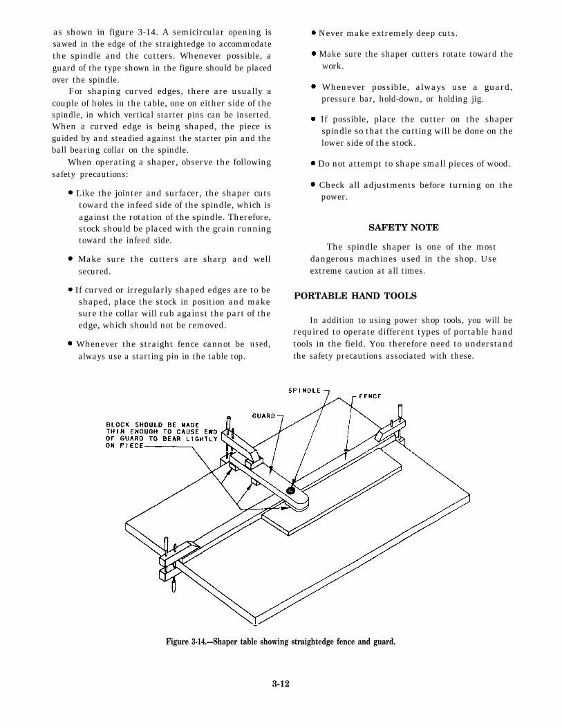
as shown in figure 3-14. A semicircular opening issawed in the edge of the straightedge to accommodatethe spindle and the cutters. Whenever possible, aguard of the type shown in the figure should be placedover the spindle.
For shaping curved edges, there are usually acouple of holes in the table, one on either side of thespindle, in which vertical starter pins can be inserted.When a curved edge is being shaped, the piece isguided by and steadied against the starter pin and theball bearing collar on the spindle.
When operating a shaper, observe the followingsafety precautions:
Like the jointer and surfacer, the shaper cutstoward the infeed side of the spindle, which isagainst the rotation of the spindle. Therefore,stock should be placed with the grain runningtoward the infeed side.
Make sure the cutters are sharp and wellsecured.
If curved or irregularly shaped edges are to beshaped, place the stock in position and makesure the collar will rub against the part of theedge, which should not be removed.
Whenever the straight fence cannot bealways use a starting pin in the table top.
used,
Never make extremely deep cuts.
Make sure the shaper cutters rotate toward thework.
Whenever possible, always use a guard,pressure bar, hold-down, or holding jig.
If possible, place the cutter on the shaperspindle so that the cutting will be done on thelower side of the stock.
Do not attempt to shape small pieces of wood.
Check all adjustments before turning on thepower.
SAFETY NOTE
The spindle shaper is one of the mostdangerous machines used in the shop. Useextreme caution at all times.
PORTABLE HAND TOOLS
In addition to using power shop tools, you will berequired to operate different types of portable handtools in the field. You therefore need to understandthe safety precautions associated with these.
Figure 3-14.—Shaper table showing straightedge fence and guard.
3-12
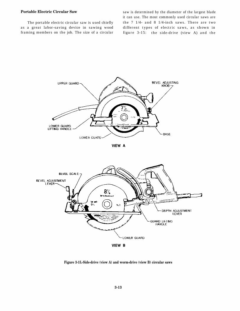
Portable Electric Circular Saw saw is determined by the diameter of the largest bladeit can use. The most commonly used circular saws are
The portable electric circular saw is used chiefly the 7 1/4- and 8 1/4-inch saws. There are twoas a great labor-saving device in sawing wood different types of electric saws, as shown inframing members on the job. The size of a circular figure 3-15: the side-drive (view A) and the
Figure 3-15.-Side-drive (view A) and worm-drive (view B) circular saws
3-13
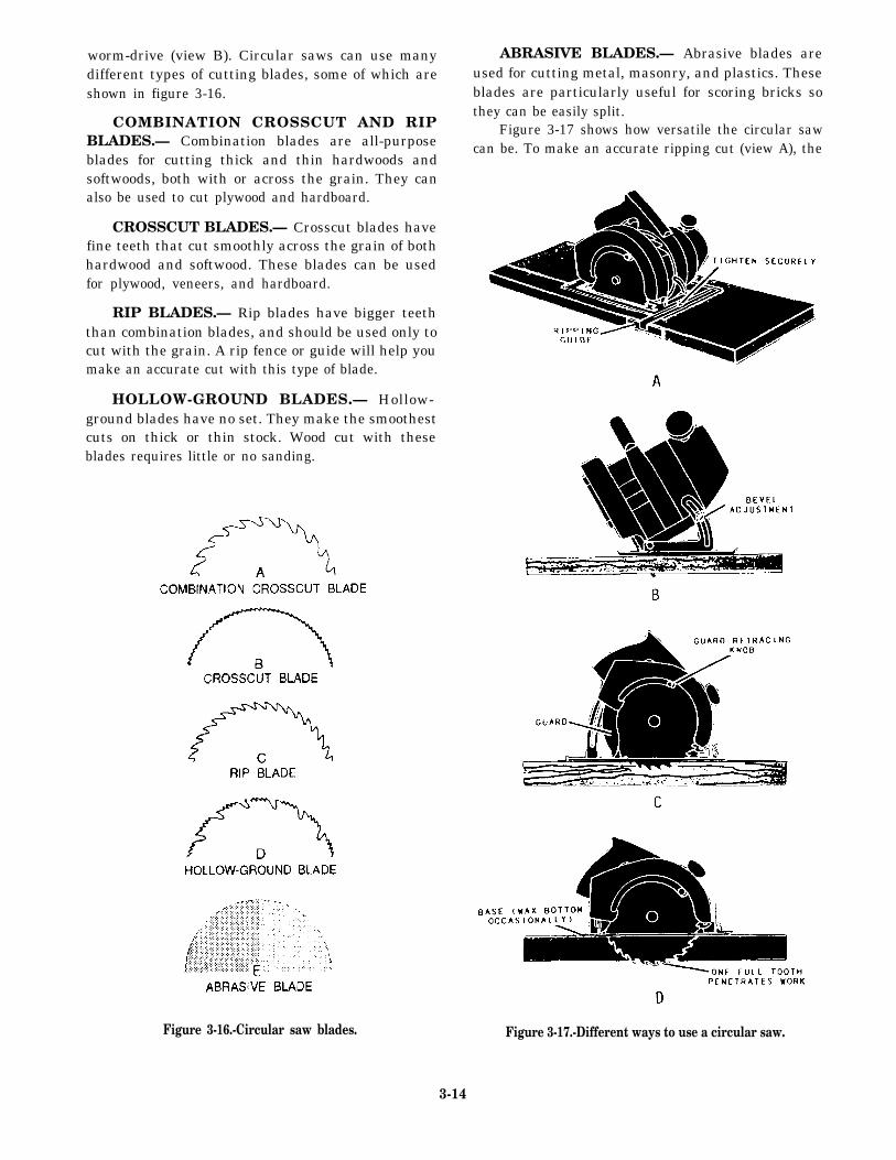
worm-drive (view B). Circular saws can use manydifferent types of cutting blades, some of which areshown in figure 3-16.
COMBINATION CROSSCUT AND RIPBLADES.— Combination blades are all-purposeblades for cutting thick and thin hardwoods andsoftwoods, both with or across the grain. They canalso be used to cut plywood and hardboard.
CROSSCUT BLADES.— Crosscut blades havefine teeth that cut smoothly across the grain of bothhardwood and softwood. These blades can be usedfor plywood, veneers, and hardboard.
RIP BLADES.— Rip blades have bigger teeththan combination blades, and should be used only tocut with the grain. A rip fence or guide will help youmake an accurate cut with this type of blade.
HOLLOW-GROUND BLADES.— Hollow-ground blades have no set. They make the smoothestcuts on thick or thin stock. Wood cut with theseblades requires little or no sanding.
ABRASIVE BLADES.— Abrasive blades areused for cutting metal, masonry, and plastics. Theseblades are particularly useful for scoring bricks sothey can be easily split.
Figure 3-17 shows how versatile the circular sawcan be. To make an accurate ripping cut (view A), the
Figure 3-16.-Circular saw blades. Figure 3-17.-Different ways to use a circular saw.
3-14
ripping guide is set a distance away from the sawequal to the width of the strip to be ripped off. It isthen placed against the edge of the piece as a guide forthe saw. To make a bevel angle cut up to 45° (viewB), you just set the bevel adjustment knob to the angleyou want and cut down the line. To make a pocket cut(views C and D), a square cut in the middle of a pieceof material, you retract the guard back and tilt the sawso that it rests on the front of the base. Then, loweringthe rear of the saw into the material, hold it there untilit goes all the way through the wood. Then, followyour line.
Observe the following safety precautions whenoperating a circular saw:
Don’t force the saw through heavy cuttingstock. If you do, you may overload the motorand damage it.
Before using the saw, carefully examine thematerial to be cut and free it of nails or othermetal objects. Cutting into or through knotsshould be avoided, if possible.
Disconnect the saw from its power sourcebefore making any adjustments or repairs tothe saw. This includes changing the blade.
Make sure all circular saws are equipped withguards that automatically y adjust themselves tothe work when in use so that none of the teethprotrude above the work. Adjust the guardover the blade so that it slides out of its recess
and covers the blade to the depth of the teethwhen you lift the saw off the work.
Wear goggles or face shields while using thesaw and while cleaning up debris afterward.
Grasp the saw with both hands and hold itfirmly against the work. Take care to preventthe saw from breaking away from the work andthereby causing injury.
Inspect the blade at frequent intervals andalways after it has locked, pinched, or burnedthe work. Disconnect the saw from the powersource before performing this inspection.
Inspect daily the electric cords that you use forcuts or breaks. Before cutting boards, makesure the cord is not in the way of the blade.
Saber Saw
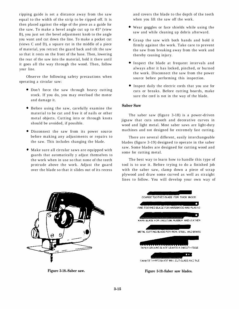
The saber saw (figure 3-18) is a power-drivenjigsaw that cuts smooth and decorative curves inwood and light metal. Most saber saws are light-dutymachines and not designed for extremely fast cutting.
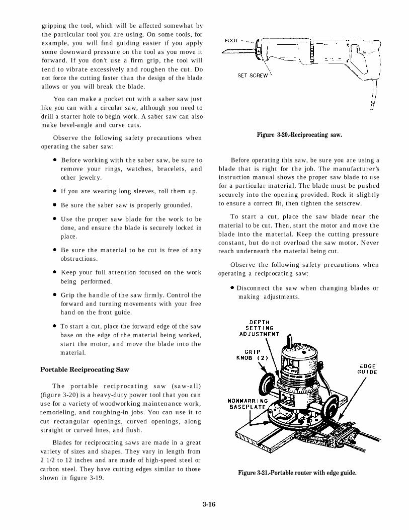
There are several different, easily interchangeableblades (figure 3-19) designed to operate in the sabersaw. Some blades are designed for cutting wood andsome for cutting metal.
The best way to learn how to handle this type oftool is to use it. Before trying to do a finished jobwith the saber saw, clamp down a piece of scrapplywood and draw some curved as well as straightlines to follow. You will develop your own way of
Figure 3-18.-Saber saw.
3-15
Figure 3-19.-Saber saw blades.
gripping the tool, which will be affected somewhat bythe particular tool you are using. On some tools, forexample, you will find guiding easier if you applysome downward pressure on the tool as you move itforward. If you don’t use a firm grip, the tool willtend to vibrate excessively and roughen the cut. Donot force the cutting faster than the design of the bladeallows or you will break the blade.
You can make a pocket cut with a saber saw justlike you can with a circular saw, although you need todrill a starter hole to begin work. A saber saw can alsomake bevel-angle and curve cuts.
Observe the following safety precautions whenoperating the saber saw:
Before working with the saber saw, be sure toremove your rings, watches, bracelets, andother jewelry.
If you are wearing long sleeves, roll them up.
Be sure the saber saw is properly grounded.
Use the proper saw blade for the work to bedone, and ensure the blade is securely locked inplace.
Be sure the material to be cut is free of anyobstructions.
Keep your full attention focused on the workbeing performed.
Grip the handle of the saw firmly. Control theforward and turning movements with your freehand on the front guide.
To start a cut, place the forward edge of the sawbase on the edge of the material being worked,start the motor, and move the blade into thematerial.
Portable Reciprocating Saw
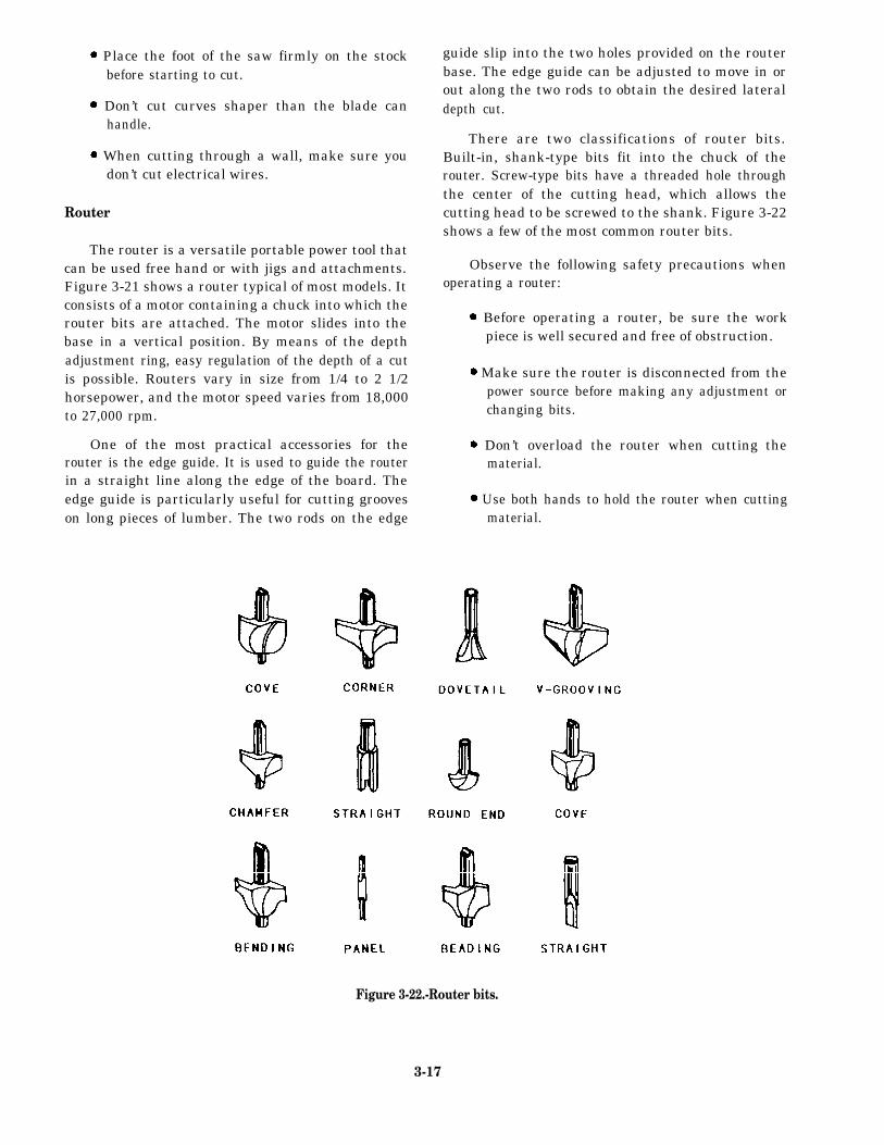
The portable reciprocating saw (saw-all)(figure 3-20) is a heavy-duty power tool that you canuse for a variety of woodworking maintenance work,remodeling, and roughing-in jobs. You can use it tocut rectangular openings, curved openings, alongstraight or curved lines, and flush.
Blades for reciprocating saws are made in a greatvariety of sizes and shapes. They vary in length from2 1/2 to 12 inches and are made of high-speed steel orcarbon steel. They have cutting edges similar to thoseshown in figure 3-19.
Figure 3-20.-Reciprocating saw.
Before operating this saw, be sure you are using ablade that is right for the job. The manufacturer’sinstruction manual shows the proper saw blade to usefor a particular material. The blade must be pushedsecurely into the opening provided. Rock it slightlyto ensure a correct fit, then tighten the setscrew.
To start a cut, place the saw blade near thematerial to be cut. Then, start the motor and move theblade into the material. Keep the cutting pressureconstant, but do not overload the saw motor. Neverreach underneath the material being cut.
Observe the following safety precautions whenoperating a reciprocating saw:
Disconnect the saw when changing blades ormaking adjustments.
Figure 3-21.-Portable router with edge guide.
3-16
Place the foot of the saw firmly on the stockbefore starting to cut.
Don’t cut curves shaper than the blade canhandle.
When cutting through a wall, make sure youdon’t cut electrical wires.
Router
The router is a versatile portable power tool thatcan be used free hand or with jigs and attachments.Figure 3-21 shows a router typical of most models. Itconsists of a motor containing a chuck into which therouter bits are attached. The motor slides into thebase in a vertical position. By means of the depthadjustment ring, easy regulation of the depth of a cutis possible. Routers vary in size from 1/4 to 2 1/2horsepower, and the motor speed varies from 18,000to 27,000 rpm.
One of the most practical accessories for therouter is the edge guide. It is used to guide the routerin a straight line along the edge of the board. Theedge guide is particularly useful for cutting grooveson long pieces of lumber. The two rods on the edge
guide slip into the two holes provided on the routerbase. The edge guide can be adjusted to move in orout along the two rods to obtain the desired lateraldepth cut.
There are two classifications of router bits.Built-in, shank-type bits fit into the chuck of therouter. Screw-type bits have a threaded hole throughthe center of the cutting head, which allows thecutting head to be screwed to the shank. Figure 3-22shows a few of the most common router bits.
Observe the following safety precautions whenoperating a router:
Before operating a router, be sure the workpiece is well secured and free of obstruction.
Make sure the router is disconnected from thepower source before making any adjustment orchanging bits.
Don’t overload the router when cutting thematerial.
Use both hands to hold the router when cuttingmaterial.
Figure 3-22.-Router bits.
3-17

Portable Power Plane
The portable electric power plane (figure 3-23) iswidely used for trimming panels, doors, frames, andso forth. It is a precision tool capable of exact depthof cut up to 3/16 inch on some of the heavier models.However, the maximum safe depth of cut on anymodel is 3/32 inch in any one pass.
The power plane is essentially a high-speed motorthat drives a cutter bar, containing either straight orspiral blades, at high speed.
Operating the power plane is simply a matter ofsetting the depth of cut and passing the plane over thework. First, make careful measurements of the piece,where it is to fit, and determine how much materialhas to be removed. Then, the stock being planedshould be held in a vise, clamped to the edge of abench, or otherwise firmly held. Check thesmoothness and straightness of all the edges.
If a smoothing cut is desired, make that cut firstand then recheck the dimensions. Make as manypasses as necessary with the plane to reach the desireddimensions, checking frequently so as not to removetoo much material. The greater the depth of the cut,the slower you must feed the tool into the work. Feedpressure should be enough to keep the tool cutting,but not so much as to slow it down excessively. Keepwood chips off the work because they can mar thesurface of the stock as the tool passes over them.Keep your hands away from the butterhead or bladeswhen a cut is finished.
The L-shaped base, or fence, of the plane shouldbe pressed snugly against the work when planing,assuring that the edge will be cut square. For bevelcuts, loosen the setscrew on the base, set the base atthe desired bevel, and then retighten the setscrew.
Figure 3-23.-Portable electric power plane.
3-18
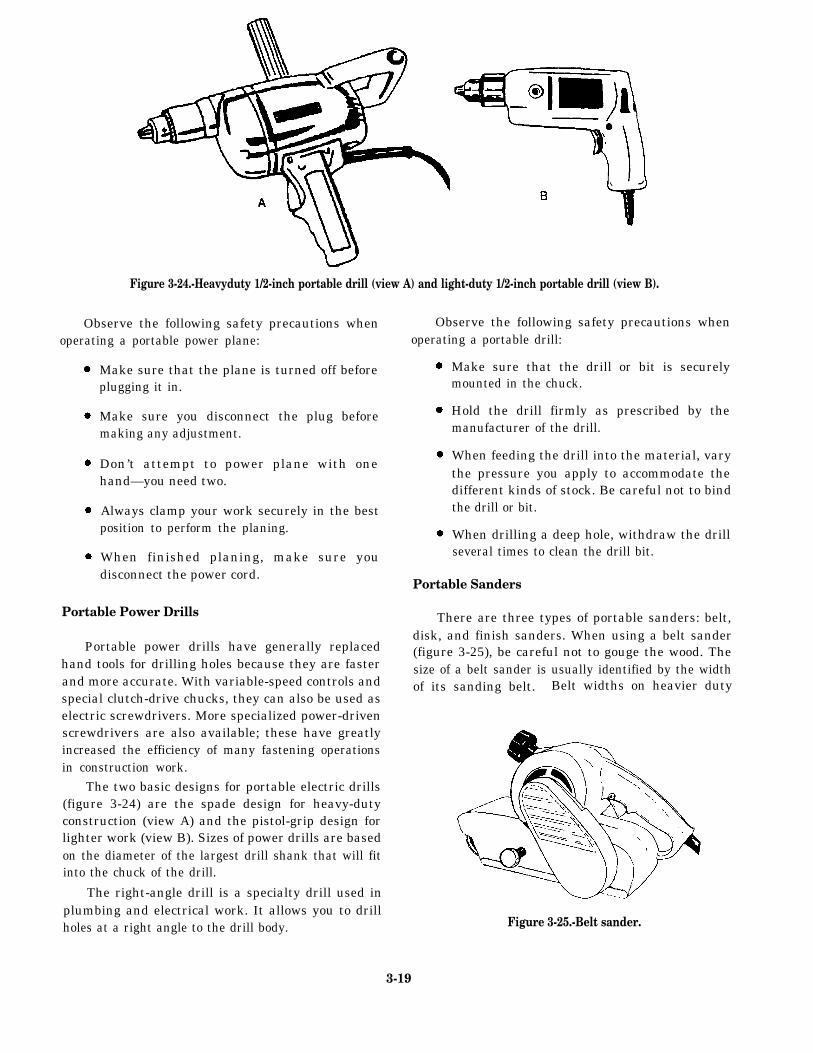
Figure 3-24.-Heavyduty 1/2-inch portable drill (view A) and light-duty 1/2-inch portable drill (view B).
Observe the following safety precautions whenoperating a portable power plane:
Make sure that the plane is turned off beforeplugging it in.
Make sure you disconnect the plug beforemaking any adjustment.
Don’t attempt to power plane with onehand—you need two.
Always clamp your work securely in the bestposition to perform the planing.
When finished planing, make sure youdisconnect the power cord.
Portable Power Drills
Portable power drills have generally replacedhand tools for drilling holes because they are fasterand more accurate. With variable-speed controls andspecial clutch-drive chucks, they can also be used aselectric screwdrivers. More specialized power-drivenscrewdrivers are also available; these have greatlyincreased the efficiency of many fastening operationsin construction work.
The two basic designs for portable electric drills(figure 3-24) are the spade design for heavy-dutyconstruction (view A) and the pistol-grip design forlighter work (view B). Sizes of power drills are basedon the diameter of the largest drill shank that will fitinto the chuck of the drill.
The right-angle drill is a specialty drill used inplumbing and electrical work. It allows you to drillholes at a right angle to the drill body.
Observe the following safety precautions whenoperating a portable drill:
Make sure that the drill or bit is securelymounted in the chuck.
Hold the drill firmly as prescribed by themanufacturer of the drill.
When feeding the drill into the material, varythe pressure you apply to accommodate thedifferent kinds of stock. Be careful not to bindthe drill or bit.
When drilling a deep hole, withdraw the drillseveral times to clean the drill bit.
Portable Sanders
There are three types of portable sanders: belt,disk, and finish sanders. When using a belt sander(figure 3-25), be careful not to gouge the wood. Thesize of a belt sander is usually identified by the widthof its sanding belt. Belt widths on heavier duty
Figure 3-25.-Belt sander.
3-19
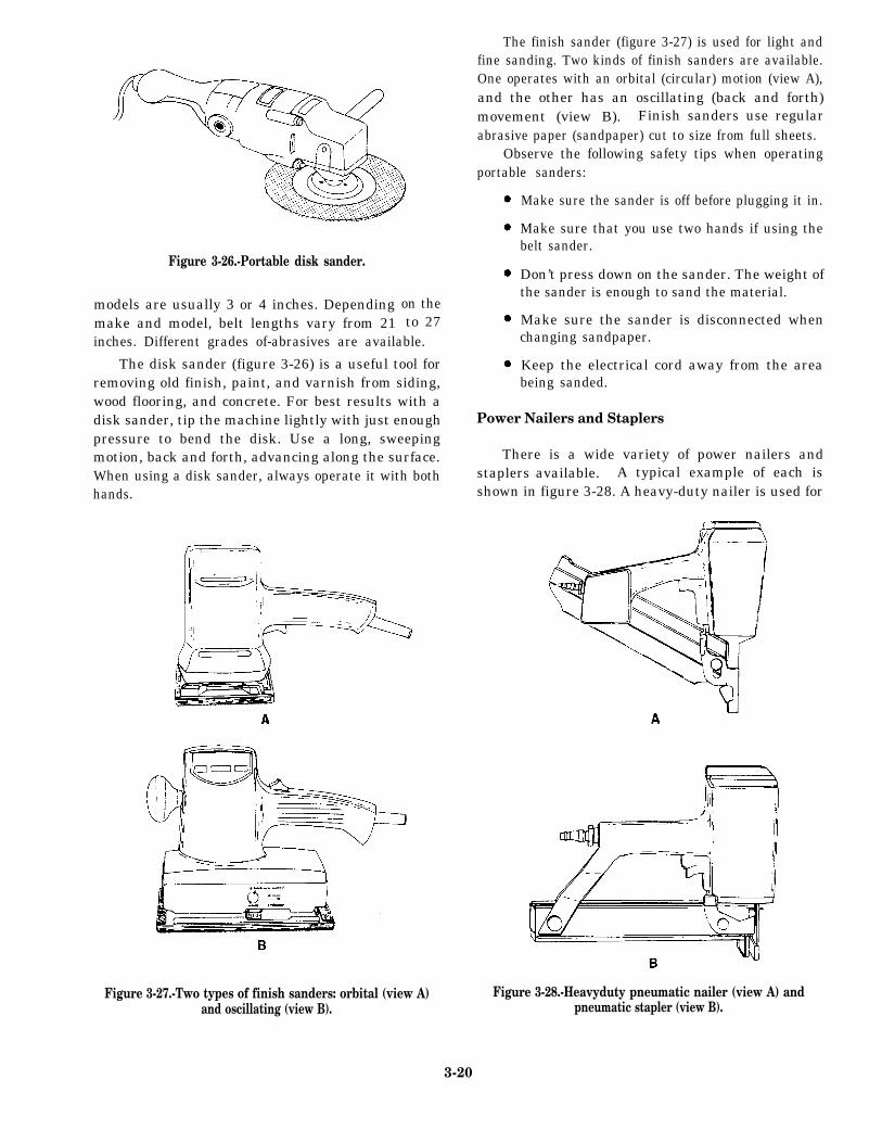
Figure 3-26.-Portable disk sander.
models are usually 3 or 4 inches. Dependingmake and model, belt lengths vary from 21
on theto 27
inches. Different grades of-abrasives are available.
The disk sander (figure 3-26) is a useful tool forremoving old finish, paint, and varnish from siding,wood flooring, and concrete. For best results with adisk sander, tip the machine lightly with just enoughpressure to bend the disk. Use a long, sweepingmotion, back and forth, advancing along the surface.When using a disk sander, always operate it with bothhands.
The finish sander (figure 3-27) is used for light andfine sanding. Two kinds of finish sanders are available.One operates with an orbital (circular) motion (view A),and the other has an oscillating (back and forth)movement (view B). Finish sanders use regularabrasive paper (sandpaper) cut to size from full sheets.
Observe the following safety tips when operatingportable sanders:
Make sure the sander is off before plugging it in.
Make sure that you use two hands if using thebelt sander.
Don’t press down on the sander. The weight ofthe sander is enough to sand the material.
Make sure the sander is disconnected whenchanging sandpaper.
Keep the electrical cord away from the areabeing sanded.
Power Nailers and Staplers
There is a wide variety of power nailers andstaplers available. A typical example of each isshown in figure 3-28. A heavy-duty nailer is used for
Figure 3-27.-Two types of finish sanders: orbital (view A)and oscillating (view B).
Figure 3-28.-Heavyduty pneumatic nailer (view A) andpneumatic stapler (view B).
3-20

framing or sheathing work; finish nailers are used forpaneling or trimming. There is also a wide variety ofstaplers that you can use for jobs, such as fasteningsheeting, decking, or roofing. These tools are oftendriven by compressed air. The amount of pneumatic,or air, pressure required to operate the tool depends onthe size of the tool and the type of operation you areperforming. Check the manufacturer’s manual for theproper air pressure to operate the tool.
The power nailer and power stapler are greattimesaving tools, but they are also very dangeroustools. Observe the following safety precautions whenusing them:
Use the correct air pressure for the particulartool and job.
Use the right nailer or stapler for the job andalso the correct nails and staples.
Keep the nose of the tool pointed away fromyour body.
When you are not using a nailer or stapler or ifyou are loading one, disconnect the airsupply.
MATERIALS
LEARNING OBJECTIVE: Upon completingthis section, you should be able to identify thetypes, sources, uses, and characteristics ofthe common woods used on variousconstruction projects.
Of all the different construction materials, woodis probably the most often used and perhaps the mostimportant. The variety of uses of wood is practicallyunlimited. Few Seabee construction projects areaccomplished without using some type of wood. It isused for permanent structures as well as concreteforms, scaffolding, shoring, and bracing, which maybe used again and again. The types, sources, uses,and characteristics of common woods are given intable 3-1. The types of classifications of wood for alarge project are usual] y designated in the projectspecifications and included in the project drawings.
Table 3-1.-Common Woods
TYPES SOURCES USES CHARACTERISTICS
Oars, boat thwarts, benches, Strong, heavy, hard, tough, elastic,gratings, hammer handles, close straight grain, shrinks very
ASH East of Rockies cabinets, ball bats, wagon little, takes excellent finish, lasts wellconstruction, farm imple-ments
Cabinetwork, imitation Similar to birch but not so durable
East of mahogany furniture, wood when exposed to weather, shrinks and
Mississippi and dowels, capping, boat trim, checks considerably, close grain,BEECH
southeastern interior finish, tool handles, light or dark red color
Canada turnery, shoe lasts, carving,flooring
East of Cabinetwork, imitation Hard, durable, fine grain, even
Mississippi River mahogany furniture, wood texture, heavy, stiff, strong, tough,
and north of gulf dowels, capping, boat trim, takes high polish, works easily, forms
BIRCH coast states, interior finish, tool handles, excellent base for white enamel
southeast turnery, carving finish, but not durable when exposed.
Canada, and Heartwood is light to dark reddish
Newfoundland brown in color
3-21
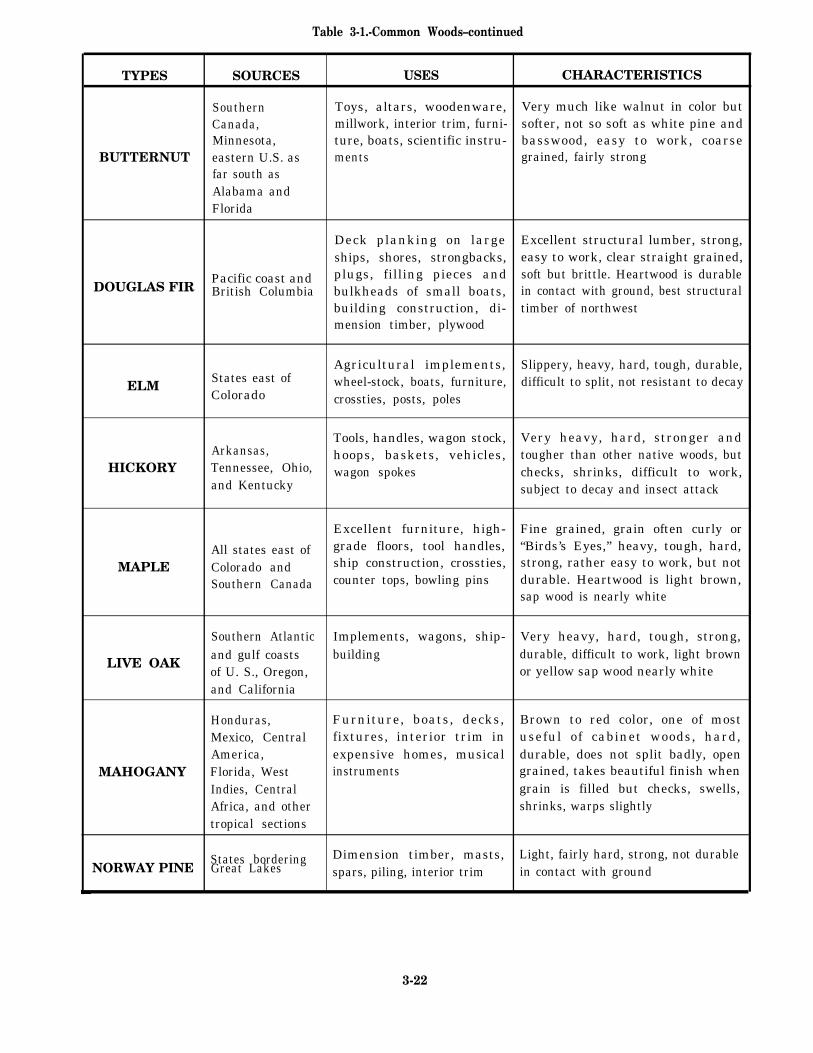
Table 3-1.-Common Woods–continued
TYPES SOURCES USES CHARACTERISTICS
Southern Toys, altars, woodenware, Very much like walnut in color butCanada, millwork, interior trim, furni- softer, not so soft as white pine andMinnesota, ture, boats, scientific instru- basswood, easy to work, coarse
BUTTERNUT eastern U.S. as ments grained, fairly strongfar south asAlabama andFlorida
Deck planking on large Excellent structural lumber, strong,ships, shores, strongbacks, easy to work, clear straight grained,
DOUGLAS FIRPacific coast and plugs, filling pieces and soft but brittle. Heartwood is durableBritish Columbia bulkheads of small boats, in contact with ground, best structural
building construction, di- timber of northwestmension timber, plywood
Agricultural implements, Slippery, heavy, hard, tough, durable,
ELMStates east of wheel-stock, boats, furniture, difficult to split, not resistant to decayColorado crossties, posts, poles
Tools, handles, wagon stock, Very heavy, hard, stronger andArkansas, hoops, baskets, vehicles, tougher than other native woods, but
HICKORY Tennessee, Ohio, wagon spokes checks, shrinks, difficult to work,and Kentucky subject to decay and insect attack
Excellent furniture, high- Fine grained, grain often curly or
All states east of grade floors, tool handles, “Birds’s Eyes,” heavy, tough, hard,
MAPLE Colorado and ship construction, crossties, strong, rather easy to work, but not
Southern Canada counter tops, bowling pins durable. Heartwood is light brown,sap wood is nearly white
Southern Atlantic Implements, wagons, ship- Very heavy, hard, tough, strong,
LIVE OAKand gulf coasts building durable, difficult to work, light brownof U. S., Oregon, or yellow sap wood nearly whiteand California
Honduras, Furniture, boats, decks, Brown to red color, one of mostMexico, Central fixtures, interior trim in useful of cabinet woods, hard,America, expensive homes, musical durable, does not split badly, open
MAHOGANY Florida, West instruments grained, takes beautiful finish whenIndies, Central grain is filled but checks, swells,Africa, and other shrinks, warps slightlytropical sections
States bordering Dimension timber, masts, Light, fairly hard, strong, not durableNORWAY PINE Great Lakes spars, piling, interior trim in contact with ground
3-22
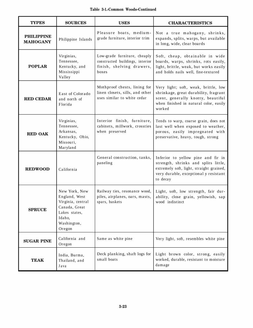
Table 3-1.-Common Woods–Continued
TYPES SOURCES USES CHARACTERISTICS
Pleasure boats, medium- Not a true mahogany, shrinks,PHILIPPINEMAHOGANY
Philippine Islands grade furniture, interior trim expands, splits, warps, but availablein long, wide, clear boards
Virginias, Low-grade furniture, cheaply Soft, cheap, obtainable in wideTennessee, constructed buildings, interior boards, warps, shrinks, rots easily,
POPLAR Kentucky, and finish, shelving drawers, light, brittle, weak, but works easilyMississippi boxes and holds nails well, fine-texturedValley
Mothproof chests, lining for Very light; soft, weak, brittle, low
East of Colorado linen closets, sills, and other shrinkage, great durability, fragrant
RED CEDAR and north of uses similar to white cedar scent, generally knotty, beautiful
Florida when finished in natural color, easilyworked
Virginias, Interior finish, furniture, Tends to warp, coarse grain, does notTennessee, cabinets, millwork, crossties last well when exposed to weather,
RED OAKArkansas, when preserved porous, easily impregnated withKentucky, Ohio, preservative, heavy, tough, strongMissouri,Maryland
General construction, tanks, Inferior to yellow pine and fir inpaneling strength, shrinks and splits little,
REDWOOD California extremely soft, light, straight grained,very durable, exceptional y resistantto decay
New York, New Railway ties, resonance wood, Light, soft, low strength, fair dur-England, West piles, airplanes, oars, masts, ability, close grain, yellowish, sapVirginia, central spars, baskets wood indistinct
SPRUCECanada, GreatLakes states,Idaho,Washington,Oregon
SUGAR PINECalifornia and Same as white pine Very light, soft, resembles white pineOregon
India, Burma, Deck planking, shaft logs for Light brown color, strong, easily
TEAK Thailand, and small boats worked, durable, resistant to moisture
Java damage
3-23
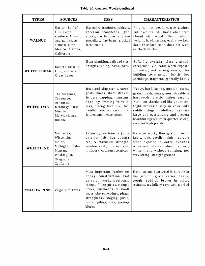
Table 3-1.-Common Woods–Continued
TYPES SOURCES USES CHARACTERISTICS
Eastern half of Expensive furniture, cabinets, Fine cabinet wood, coarse grainedU.S. except interior woodwork, gun but takes beautiful finish when poressouthern Atlantic stocks, tool handles, airplane closed with wood filler, medium
WALNUT and gulf coasts, propellers, fine boats, musical weight, hard, strong, easily worked,some in New instruments dark chocolate color, does not warpMexico, Arizona, or check brittleCalifornia
Boat planking, railroad ties, Soft, lightweight, close grained,
Eastern coast of shingles, siding, posts, poles exceptionally durable when exposed
WHITE CEDAR U. S., and around to water, not strong enough for
Great Lakes building construction, brittle, lowshrinkage, fragment, generally knotty
Boat and ship stems, stern- Heavy, hard, strong, medium coarse
The Virginias, posts, knees, sheer strakes, grain, tough, dense, most durable of
Tennessee, fenders, capping, transoms, hardwoods, elastic, rather easy to
Arkansas, shaft logs, framing for build- work, but shrinks and likely to check.
WHITE OAK Kentucky, Ohio, ings, strong furniture, tool Light brownish grey in color with
Missouri, handles, crossties, agricultural reddish tinge, medullary rays are
Maryland, and implements, fence posts large and outstanding and present
Indiana beautiful figures when quarter sawed,receives high polish
Minnesota, Patterns, any interior job or Easy to work, fine grain, free ofWisconsin, exterior job that doesn’t knots, takes excellent finish, durableMaine, require maximum strength, when exposed to water, expands
WHITE PINEMichigan, Idaho, window sash, interior trim, when wet, shrinks when dry, soft,Montana, millwork, cabinets, cornices white, nails without splitting, notWashington, very strong, straight grainedOregon, andCalifornia
Most important lumber for Hard, strong, heartwood is durable inheavy construction and the ground, grain varies, heavy,exterior work, keelsons, tough, reddish brown in color,risings, filling pieces, clamps, resinous, medullary rays well marked
YELLOW PINE Virginia to Texas floors, bulkheads of smallboats, shores, wedges, plugs,strongbacks, staging, joists,posts, piling, ties, pavingblocks
3-24
LUMBER
The terms "wood" "lumber," and "timber" areoften spoken of or written in ways to suggest that theirmeanings are alike or nearly so. But in the Builder’slanguage, the terms have distinct, separate meanings.Wood is the hard, fibrous substance that forms themajor part of the trunk and branches of a tree.Lumber is wood that has been cut and surfaced for usein construction work. Timber is lumber that is5 inches or more in both thickness and width.
SEASONING OF LUMBER
Seasoning of lumber is the result of removingmoisture from the small and large cells of wood—drying. The advantages of seasoning lumber are toreduce its weight; increase its strength and resistanceto decay; and decrease shrinkage, which tends toavoid checking and warping after lumber is placed. Aseldom used and rather slow method of seasoninglumber is air-drying in a shed or stacking in the open
until dry. A faster method, known as kiln drying, haslumber placed in a large oven or kiln and dried withheat, supplied by gas- or oil-fired burners. Lumber isconsidered dry enough for most uses when its moisturecontent has been reduced to about 12 or 15 percent. Asa Builder, you will learn to judge the dryness of lumberby its color, weight, smell, and feel. Also, after thelumber is cut, you will be able to judge the moisturecontent by looking at the shavings and chips.
DEFECTS AND BLEMISHES
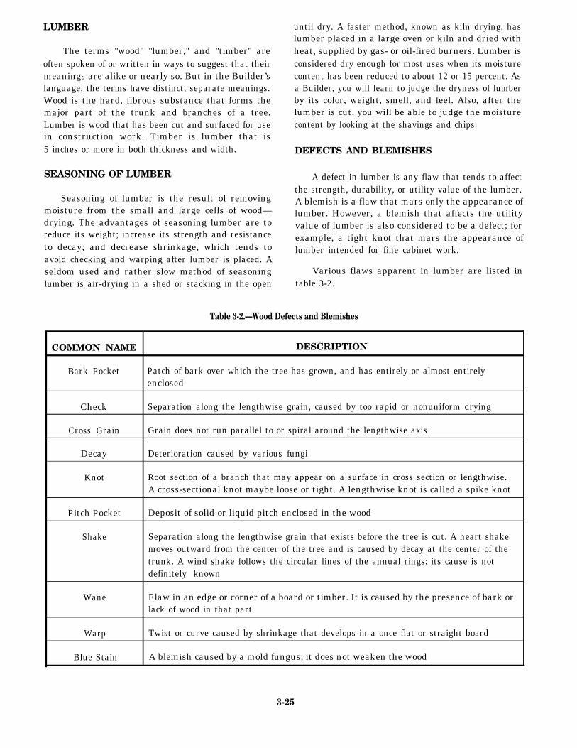
A defect in lumber is any flaw that tends to affectthe strength, durability, or utility value of the lumber.A blemish is a flaw that mars only the appearance oflumber. However, a blemish that affects the utilityvalue of lumber is also considered to be a defect; forexample, a tight knot that mars the appearance oflumber intended for fine cabinet work.
Various flaws apparent in lumber are listed intable 3-2.
Table 3-2.—Wood Defects and Blemishes
COMMON NAME DESCRIPTION
Bark Pocket Patch of bark over which the tree has grown, and has entirely or almost entirelyenclosed
Check Separation along the lengthwise grain, caused by too rapid or nonuniform drying
Cross Grain Grain does not run parallel to or spiral around the lengthwise axis
Decay Deterioration caused by various fungi
Knot Root section of a branch that may appear on a surface in cross section or lengthwise.A cross-sectional knot maybe loose or tight. A lengthwise knot is called a spike knot
Pitch Pocket Deposit of solid or liquid pitch enclosed in the wood
Shake Separation along the lengthwise grain that exists before the tree is cut. A heart shakemoves outward from the center of the tree and is caused by decay at the center of thetrunk. A wind shake follows the circular lines of the annual rings; its cause is notdefinitely known
Wane Flaw in an edge or corner of a board or timber. It is caused by the presence of bark orlack of wood in that part
Warp Twist or curve caused by shrinkage that develops in a once flat or straight board
Blue Stain A blemish caused by a mold fungus; it does not weaken the wood
3-25
CLASSIFICATION OF LUMBER
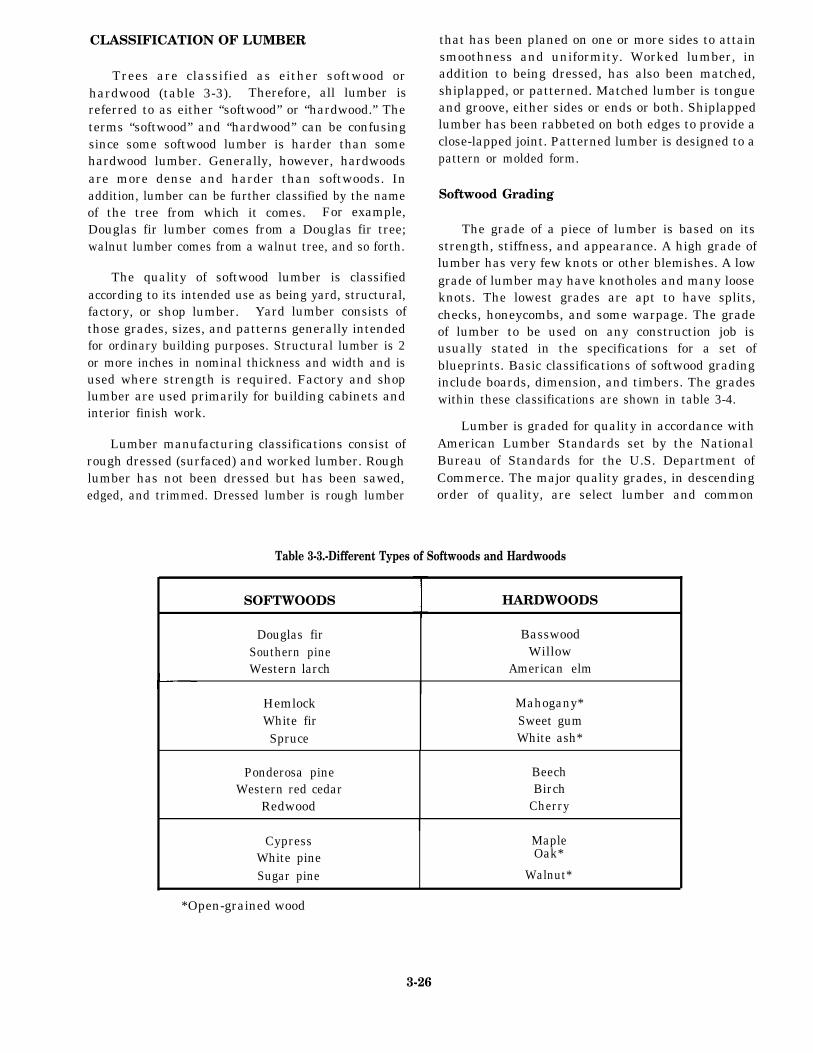
Trees are classified as either softwood orhardwood (table 3-3). Therefore, all lumber isreferred to as either “softwood” or “hardwood.” Theterms “softwood” and “hardwood” can be confusingsince some softwood lumber is harder than somehardwood lumber. Generally, however, hardwoodsare more dense and harder than softwoods. Inaddition, lumber can be further classified by the nameof the tree from which it comes. For example,Douglas fir lumber comes from a Douglas fir tree;walnut lumber comes from a walnut tree, and so forth.
The quality of softwood lumber is classifiedaccording to its intended use as being yard, structural,factory, or shop lumber. Yard lumber consists ofthose grades, sizes, and patterns generally intendedfor ordinary building purposes. Structural lumber is 2or more inches in nominal thickness and width and isused where strength is required. Factory and shoplumber are used primarily for building cabinets andinterior finish work.
Lumber manufacturing classifications consist ofrough dressed (surfaced) and worked lumber. Roughlumber has not been dressed but has been sawed,edged, and trimmed. Dressed lumber is rough lumber
that has been planed on one or more sides to attainsmoothness and uniformity. Worked lumber, inaddition to being dressed, has also been matched,shiplapped, or patterned. Matched lumber is tongueand groove, either sides or ends or both. Shiplappedlumber has been rabbeted on both edges to provide aclose-lapped joint. Patterned lumber is designed to apattern or molded form.
Softwood Grading
The grade of a piece of lumber is based on itsstrength, stiffness, and appearance. A high grade oflumber has very few knots or other blemishes. A lowgrade of lumber may have knotholes and many looseknots. The lowest grades are apt to have splits,checks, honeycombs, and some warpage. The gradeof lumber to be used on any construction job isusually stated in the specifications for a set ofblueprints. Basic classifications of softwood gradinginclude boards, dimension, and timbers. The gradeswithin these classifications are shown in table 3-4.
Lumber is graded for quality in accordance withAmerican Lumber Standards set by the NationalBureau of Standards for the U.S. Department ofCommerce. The major quality grades, in descendingorder of quality, are select lumber and common
Table 3-3.-Different Types of Softwoods and Hardwoods
SOFTWOODS HARDWOODS
Douglas fir BasswoodSouthern pine WillowWestern larch American elm
Hemlock Mahogany*White fir Sweet gumSpruce White ash*
Ponderosa pine BeechWestern red cedar Birch
Redwood Cherry
Cypress MapleWhite pine Oak*
Sugar pine Walnut*
*Open-grained wood
3-26
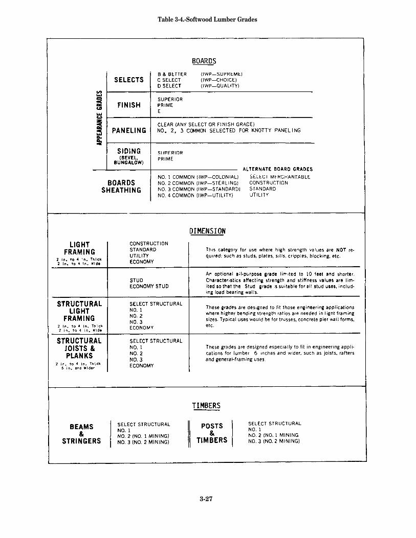
Table 3-4.-Softwood Lumber Grades
3-27
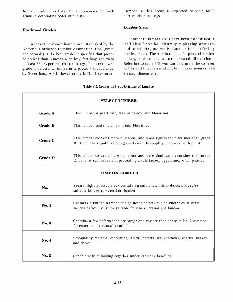
lumber. Table 3-5 lists the subdivisions for eachgrade in descending order of quality.
Hardwood Grades
Grades of hardwood lumber are established by theNational Hardwood Lumber Association. FAS (firstsand seconds) is the best grade. It specifies that piecesbe no less than 6-inches wide by 8-feet long and yieldat least 83 1/3 percent clear cuttings. The next lowergrade is selects, which permits pieces 4-inches wideby 6-feet long. A still lower grade is No. 1 common.
Lumber in this group is expected to yield 6623percent clear cuttings.
Lumber Sizes
Standard lumber sizes have been established inthe United States for uniformity in planning structuresand in ordering materials. Lumber is identified bynominal sizes. The nominal size of a piece of lumberis larger than the actual dressed dimensions.Referring to table 3-6, you can determine the commonwidths and thicknesses of lumber in their nominal anddressed dimensions.
Table 3-5.-Grades and Subdivisions of Lumber
SELECT LUMBER
Grade A This lumber is practically free of defects and blemishes
Grade B This lumber contains a few minor blemishes
Grade CThis lumber contains more numerous and more significant blemishes than gradeB. It must be capable of being easily and thoroughly concealed with paint
Grade DThis lumber contains more numerous and more significant blemishes than gradeC, but it is still capable of presenting a satisfactory appearance when painted
COMMON LUMBER
No. 1Sound, tight-knotted stock containing only a few minor defects. Must besuitable for use as watertight lumber
No. 2Contains a limited number of significant defects but no knotholes or otherserious defects. Must be suitable for use as grain-tight lumber
No. 3Contains a few defects that are larger and coarser than those in No. 2 common;for example, occasional knotholes
No. 4Low-quality material containing serious defects like knotholes, checks, shakes,and decay
No. 5 Capable only of holding together under ordinary handling
3-28
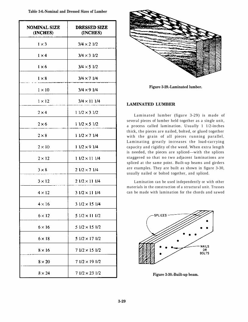
Table 3-6.-Nominal and Dressed Sizes of Lumber
Figure 3-29.-Laminated lumber.
LAMINATED LUMBER
Laminated lumber (figure 3-29) is made ofseveral pieces of lumber held together as a single unit,a process called lamination. Usually 1 1/2-inchesthick, the pieces are nailed, bolted, or glued togetherwith the grain of all pieces running parallel.Laminating greatly increases the load-carryingcapacity and rigidity of the weed. When extra lengthis needed, the pieces are spliced—with the splicesstaggered so that no two adjacent laminations arespliced at the same point. Built-up beams and girdersare examples. They are built as shown in figure 3-30,usually nailed or bolted together, and spliced.
Lamination can be used independently or with othermaterials in the construction of a structural unit. Trussescan be made with lamination for the chords and sawed
Figure 3-30.-Built-up beam.
3-29
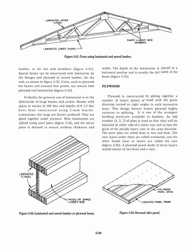
Figure 3-31.-Truss using laminated and sawed lumber.
lumber, or for the web members (figure 3-31).Special beams can be constructed with lamination forthe flanges and plywood or sawed lumber, for theweb, as shown in figure 3-32. Units, such as plywoodbox beams and stressed skin panels, can contain bothplywood and lamination (figure 3-33).
Probably the greatest use of lamination is in thefabrication of large beams and arches. Beams withspans in excess of 100 feet and depths of 8 1/2 feethave been constructed using 2-inch boards.Laminations this large are factory produced. They areglued together under pressure. Most laminations arespliced using scarf joints (figure 3-34), and the entirepiece is dressed to ensure uniform thickness and
Figure 3-32.-Laminated and sawed lumber or plywood beam.
width. The depth of the lamination ishorizontal position and is usually the full
placed in awidth of the
beam (figure 3-35).
PLYWOOD
Plywood is constructednumber of layers (plies) of
by gluing together awood with the grain
direction turned at right angles in each successivelayer. This design feature makes plywood highlyresistant to splitting. It is one of the strongestbuilding materials available to Seabees. An oddnumber (3, 5, 7) of plies is used so that they will bebalanced on either side of a center core and so that thegrain of the outside layers runs in the same direction.The outer plies are called faces or face and back. Thenext layers under these are called crossbands, and theother inside layer or layers are called the core(figure 3-36). A plywood panel made of three layerswould consist of two faces and a core.
Figure 3-33.-Stressed skin panel.
3-30
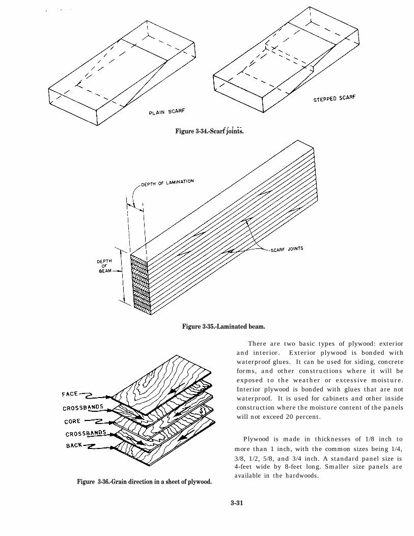
Figure 3-34.-Scarf joints.
Figure 3-35.-Laminated beam.
There are two basic types of plywood: exteriorand interior. Exterior plywood is bonded withwaterproof glues. It can be used for siding, concreteforms, and other constructions where it will beexposed to the weather or excessive moisture.Interior plywood is bonded with glues that are notwaterproof. It is used for cabinets and other insideconstruction where the moisture content of the panelswill not exceed 20 percent.
Figure 3-36.-Grain direction in a sheet of plywood.
Plywood is made in thicknesses of 1/8 inch tomore than 1 inch, with the common sizes being 1/4,3/8, 1/2, 5/8, and 3/4 inch. A standard panel size is4-feet wide by 8-feet long. Smaller size panels areavailable in the hardwoods.
3-31
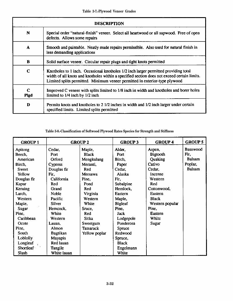
Table 3-7.-Plywood Veneer Grades
Table 3-8.-Classification of Softwood Plywood Rates Species for Strength and Stiffness
3-32
Plywood can be worked quickly and easily withcommon carpentry tools. It holds nails well andnormally does not split when nails are driven close tothe edges. Finishing plywood presents no unusualproblems; it can be sanded or texture coated with apermanent finish or left to weather naturally.
There is probably no other building material asversatile as plywood. It is used for concrete forms, walland roof sheathing, flooring, box beams, soffits,stressed-skin panels, paneling, shelving, doors,furniture, cabinets, crates, signs, and many other items.
Softwood Plywood Grades
All plywood panels are quality graded based onproducts standards (currently PS 1/74). The grade ofeach type of plywood is determined by the kind ofveneer (N, A, B, C, or D) used for the face and back ofthe panel and by the type of glue used in construction.The plywood veneer grades are shown in table 3-7.
Many species of softwood are used in makingplywood. There are five separate plywood groupsbased on stiffness and strength. Group 1 includes thestiffest and strongest; group 5 includes the weakestwoods. A listing of groupings and associated woodsis shown in table 3-8.
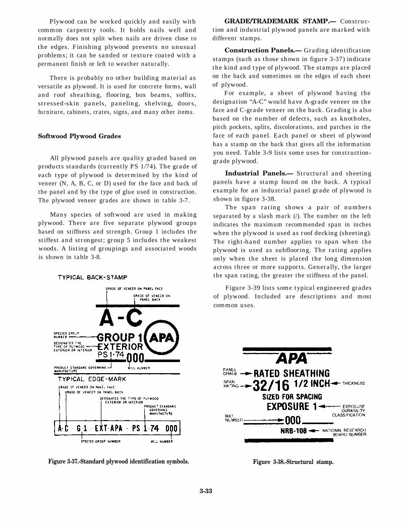
Figure 3-37.-Standard plywood identification symbols.
GRADE/TRADEMARK STAMP.— Construc-tion and industrial plywood panels are marked withdifferent stamps.
Construction Panels.— Grading identificationstamps (such as those shown in figure 3-37) indicatethe kind and type of plywood. The stamps are placedon the back and sometimes on the edges of each sheetof plywood.
For example, a sheet of plywood having thedesignation “A-C” would have A-grade veneer on theface and C-grade veneer on the back. Grading is alsobased on the number of defects, such as knotholes,pitch pockets, splits, discolorations, and patches in theface of each panel. Each panel or sheet of plywoodhas a stamp on the back that gives all the informationyou need. Table 3-9 lists some uses for construction-grade plywood.
Industrial Panels.— Structural and sheetingpanels have a stamp found on the back. A typicalexample for an industrial panel grade of plywood isshown in figure 3-38.
The span rating shows a pair of numbersseparated by a slash mark (/). The number on the leftindicates the maximum recommended span in incheswhen the plywood is used as roof decking (sheeting).The right-hand number applies to span when theplywood is used as subflooring. The rating appliesonly when the sheet is placed the long dimensionacross three or more supports. Generally, the largerthe span rating, the greater the stiffness of the panel.
Figure 3-39 lists some typical engineered gradesof plywood. Included are descriptions and mostcommon uses.
Figure 3-38.-Structural stamp.
3-33
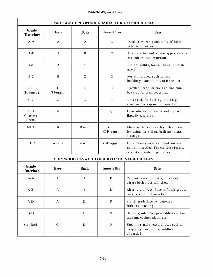
Table 3-9.-Plywood Uses
SOFTWOOD PLYWOOD GRADES FOR EXTERIOR USES
Grade(Exterior)
Face Back Inner Plies Uses
A-A A A C Outdoor where appearance of bothsides is important
A-B A B C Alternate for A-A where appearance ofone side is less important
A-C A C C Siding, soffits, fences. Face is finishgrade
B-C B C C For utility uses, such as farmbuildings, some kinds of fences, etc.
C-C C C C Excellent base for tile and linoleum,(Plugged) (Plugged) backing for wall coverings
C-C C C C Unsanded, for backing and roughconstruction exposed to weather
B-B B B C Concrete forms. Reuse until woodConcrete literally wears out
Forms
MDO B B or C C or Medium density overlay. Ideal baseC-Plugged for paint; for siding, built-ins, signs,
displays
HDO A or B A or B C-Plugged High density overlay. Hard surface;no paint needed. For concrete forms,cabinets, counter tops, tanks
SOFTWOOD PLYWOOD GRADES FOR INTERIOR USES
Grade(Interior)
Face Back Inner Plies Uses
A-A A A D Cabinet doors, built-ins, furniturewhere both sides will show
A-B A B D Alternate of A-A. Face is finish grade,back is solid and smooth
A-D A D D Finish grade face for paneling,built-ins, backing
B-D B D D Utility grade. One paintable side. Forbacking, cabinet sides, etc
Standard C D D Sheathing and structural uses such astemporary enclosures, subfloor.Unsanded
3-34
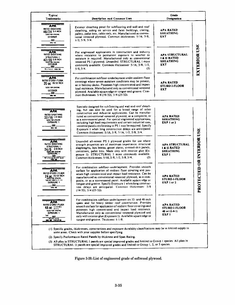
Figure 3-39.-List of engineered grade of softwood plywood.
3-35
Exposure Ratings.— The grade/trademark stamplists the exposure durability classification for plywood.There are two basic types or ratings: exterior andinterim. The exterior type has a 100-percent waterproofglue line, and the interior type has a highlymoisture-resistant glue line. However, panels can bemanufactured in three exposure durabilityclassifications: Exterior, Exposure 1, and Exposure 2.
Panels marked “Exterior” can be used where thereis continual exposure to weather and moisture. Panelsmarked “Exposure 1“ can withstand moisture duringextended periods, but they should be used onlyindoors. Panels marked “Exposure 2“ can be used inprotected locations. They may be subjected to somewater leakage or high humidity but generally shouldbe protected from weather.
Most plywood is made withglue. However, interior panelsintermediate or interior glue.
Hardwood Plywood Grades
waterproof exteriormay be made with
Hardwood plywood panels are primarily used fordoor skins, cabinets, and wall paneling. TheHardwood Plywood Manufacturers’ Association hasestablished a grading system with the followinggrades: premium (A), good grade (1), sound grade(2), utility grade (3), and backing grade (4). Forexample, an A-3 grade hardwood plywood wouldhave a premium face and a utility back. A 1-1 gradewould have a good face and a good back.
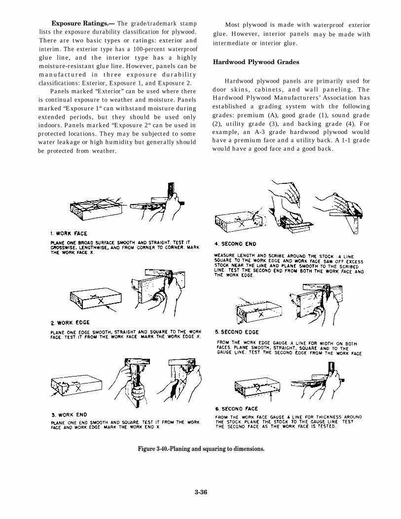
Figure 3-40.-Planing and squaring to dimensions.
3-36
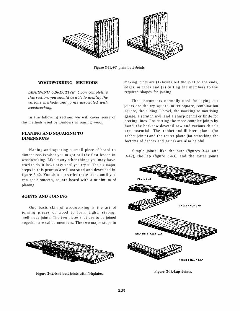
Figure 3-41.-90° plain butt Joints.
WOODWORKING METHODS
LEARNING OBJECTIVE: Upon completingthis section, you should be able to identify thevarious methods and joints associated withwoodworking.
In the following section, we will cover some ofthe methods used by Builders in joining wood.
PLANING AND SQUARING TODIMENSIONS
Planing and squaring a small piece of board todimensions is what you might call the first lesson inwoodworking. Like many other things you may havetried to do, it looks easy until you try it. The six majorsteps in this process are illustrated and described infigure 3-40. You should practice these steps until youcan get a smooth, square board with a minimum ofplaning.
JOINTS AND JOINING
One basic skill of woodworking is the art ofjoining pieces of wood to form tight, strong,well-made joints. The two pieces that are to be joinedtogether are called members. The two major steps in
making joints are (1) laying out the joint on the ends,edges, or faces and (2) cutting the members to therequired shapes for joining.
The instruments normally used for laying outjoints are the try square, miter square, combinationsquare, the sliding T-bevel, the marking or mortisinggauge, a scratch awl, and a sharp pencil or knife forscoring lines. For cutting the more complex joints byhand, the hacksaw dovetail saw and various chiselsare essential. The rabbet-and-fillister plane (forrabbet joints) and the router plane (for smoothing thebottoms of dadoes and gains) are also helpful.
Simple joints, like the butt (figures 3-41 and3-42), the lap (figure 3-43), and the miter joints
Figure 3-42.-End butt joints with fishplates.
3-37
Figure 3-43.-Lap Joints.
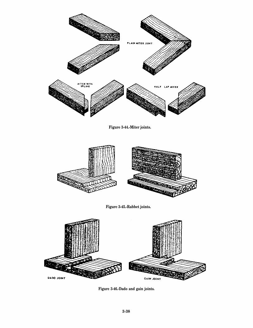
Figure 3-44.-Miter joints.
Figure 3-45.-Rabbet joints.
Figure 3-46.-Dado and gain joints.
3-38
(figure 3-44), are used mostly in rough or finish
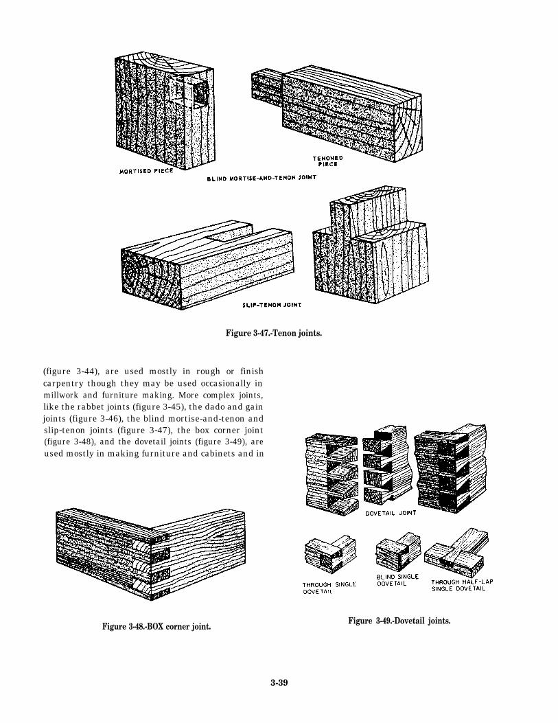
Figure 3-47.-Tenon joints.
carpentry though they may be used occasionally inmillwork and furniture making. More complex joints,like the rabbet joints (figure 3-45), the dado and gainjoints (figure 3-46), the blind mortise-and-tenon andslip-tenon joints (figure 3-47), the box corner joint(figure 3-48), and the dovetail joints (figure 3-49), areused mostly in making furniture and cabinets and in
Figure 3-48.-BOX corner joint.Figure 3-49.-Dovetail joints.
3-39
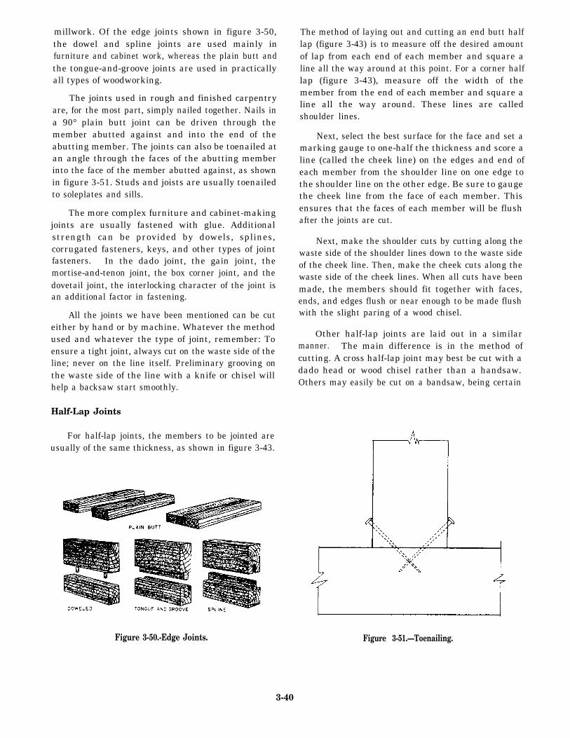
millwork. Of the edge joints shown in figure 3-50,the dowel and spline joints are used mainly infurniture and cabinet work, whereas the plain butt andthe tongue-and-groove joints are used in practicallyall types of woodworking.
The joints used in rough and finished carpentryare, for the most part, simply nailed together. Nails ina 90° plain butt joint can be driven through themember abutted against and into the end of theabutting member. The joints can also be toenailed atan angle through the faces of the abutting memberinto the face of the member abutted against, as shownin figure 3-51. Studs and joists are usually toenailedto soleplates and sills.
The more complex furniture and cabinet-makingjoints are usually fastened with glue. Additionalstrength can be provided by dowels, splines,corrugated fasteners, keys, and other types of jointfasteners. In the dado joint, the gain joint, themortise-and-tenon joint, the box corner joint, and thedovetail joint, the interlocking character of the joint isan additional factor in fastening.
All the joints we have been mentioned can be cuteither by hand or by machine. Whatever the methodused and whatever the type of joint, remember: Toensure a tight joint, always cut on the waste side of theline; never on the line itself. Preliminary grooving onthe waste side of the line with a knife or chisel willhelp a backsaw start smoothly.
Half-Lap Joints
For half-lap joints, the members to be jointed areusually of the same thickness, as shown in figure 3-43.
The method of laying out and cutting an end butt halflap (figure 3-43) is to measure off the desired amountof lap from each end of each member and square aline all the way around at this point. For a corner halflap (figure 3-43), measure off the width of themember from the end of each member and square aline all the way around. These lines are calledshoulder lines.
Next, select the best surface for the face and set amarking gauge to one-half the thickness and score aline (called the cheek line) on the edges and end ofeach member from the shoulder line on one edge tothe shoulder line on the other edge. Be sure to gaugethe cheek line from the face of each member. Thisensures that the faces of each member will be flushafter the joints are cut.
Next, make the shoulder cuts by cutting along thewaste side of the shoulder lines down to the waste sideof the cheek line. Then, make the cheek cuts along thewaste side of the cheek lines. When all cuts have beenmade, the members should fit together with faces,ends, and edges flush or near enough to be made flushwith the slight paring of a wood chisel.
Other half-lap joints are laid out in a similarmanner. The main difference is in the method ofcutting. A cross half-lap joint may best be cut with adado head or wood chisel rather than a handsaw.Others may easily be cut on a bandsaw, being certain
Figure 3-50.-Edge Joints. Figure 3-51.—Toenailing.
3-40
to cut on the waste side of the lines and making alllines from the face of the material.
Miter Joints
A miter joint is made by mitering (cutting at anangle) the ends or edges of the members that are to bejoined together (figure 3-44). The angle of the mitercut is one-half of the angle formed by the joinedmembers. In rectangular mirror frames, windows,door casing boxes, and the like, adjacent membersform a 90° angle, and, consequently, the correct anglefor mitering is one-half of 90°, or 45°. For membersforming an equal-sided figure with other than foursides (such as an octagon or a pentagon), the correctmitering angle can be found by dividing the numberof sides the figure will have into 180° and subtractingthe result from 90°. For an octagon (an eight-sidedfigure), determine the mitering angle by subtractingfrom 90°180° divided by 8 or 90° minus 22.5° equals67.5°. For a pentagon (a five-sided figure), the angle is
Members can be end mitered to 45° in the woodenmiter box and to any angle in the steel miter box bysetting the saw to the desired angle, or on the circularsaw, by setting the miter gauge to the desired angle.Members can be edge mitered to any angle on thecircular saw by tilting the saw to the required angle.
Sawed edges are sometimes unsuitable for gluing.However, if the joint is to be glued, the edges can bemitered on a jointer, as shown in figure 3-52.
SAFETY NOTE
This is a dangerous operation and cautionshould be taken.
Since abutting surfaces of end-mitered membersdo not hold well when they are merely glued, theyshould be reinforced. One type of reinforcement isthe corrugated fastener. This is a corrugated strip ofmetal with one edge sharpened for driving into thejoint. The fastener is placed at a right angle to the linebetween the members, half on one member and halfon the other, and driven down flush with the member.The corrugated fastener mars the appearance of thesurface into which it is driven; therefore, it is usedonly on the backs of picture frames and the like.
A more satisfactory type of fastener for a jointbetween end-mitered members is the slip feather.This is a thin piece of wood or veneer that is glued
Figure 3-52.-Beveling on a jointer for a mitered edge joint.
into a kerf cut in the thickest dimension of the joint.First, saw about halfway through the wood from theouter to the inner corner, then apply glue to both sidesof the slip feather, pushing the slip feather into thekerf. Clamp it tightly and allow the glue to dry. Afterit has dried, remove the clamp and chisel off theprotruding portion of the slip feather.
A joint between edge-mitered members can alsobe reinforced with a spline. This is a thick piece ofwood that extends across the joint into grooves cut inthe abutting surfaces. A spline for a plain miter jointis shown in figure 3-44. The groove for a spline canbe cut either by hand or by a circular saw.
Grooved Joints
A three-sided recess running with the grain is calleda groove, and a recess running across the grain is calleda dado. A groove or dado that does not extend all theway across the wood is called a stopped groove or astopped dado. A stopped dado is also known as a gain(figure 3-46). A two-sided recess running along an edgeis called a rabbet T (figure 3-45). Dadoes, gains, andrabbets are not, strictly speaking, grooves; but joints thatinclude them are generally called grooved joints.
A groove or dado can be cut with a circular saw asfollows: Lay out the groove or dado on the end wood(for a groove) or edge wood (for a dado) that will firstcome in contact with the saw. Set the saw to thedesired depth of the groove above the table, and set
3-41
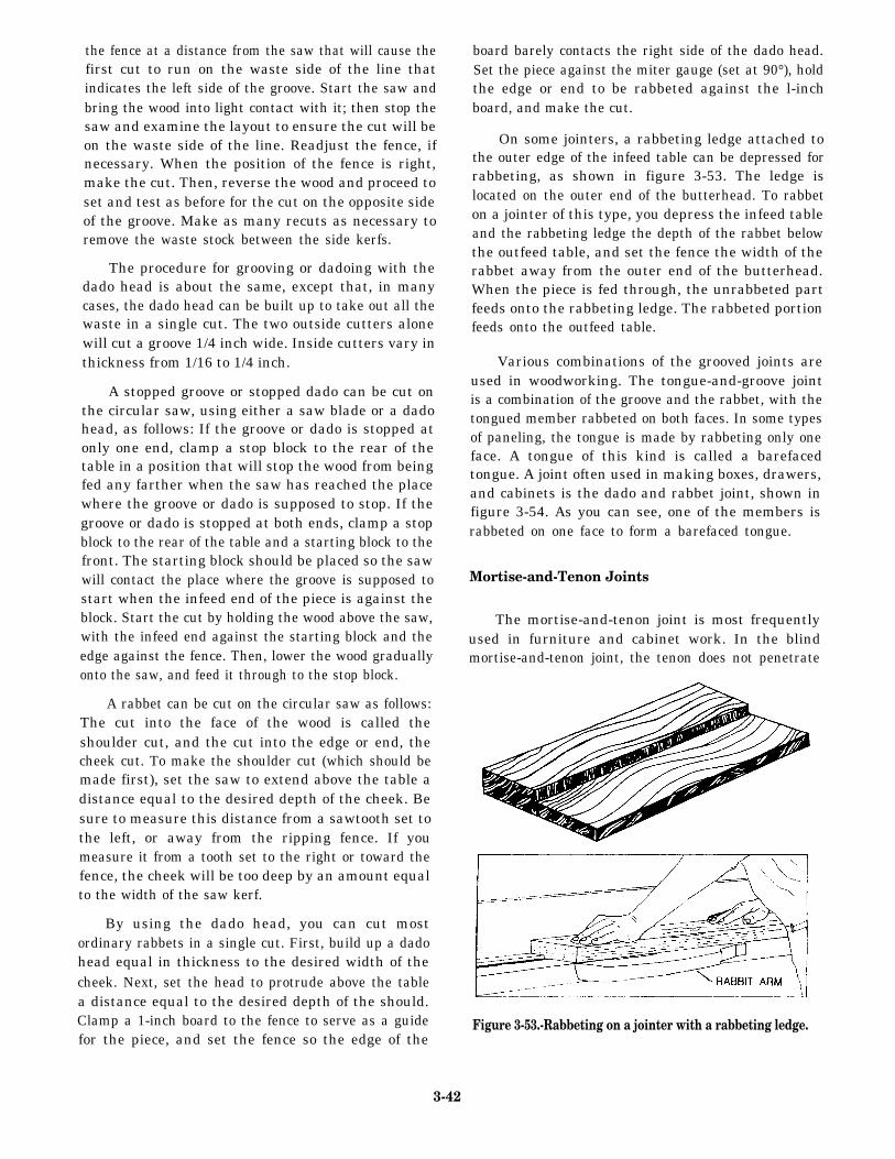
the fence at a distance from the saw that will cause thefirst cut to run on the waste side of the line thatindicates the left side of the groove. Start the saw andbring the wood into light contact with it; then stop thesaw and examine the layout to ensure the cut will beon the waste side of the line. Readjust the fence, ifnecessary. When the position of the fence is right,make the cut. Then, reverse the wood and proceed toset and test as before for the cut on the opposite sideof the groove. Make as many recuts as necessary toremove the waste stock between the side kerfs.
The procedure for grooving or dadoing with thedado head is about the same, except that, in manycases, the dado head can be built up to take out all thewaste in a single cut. The two outside cutters alonewill cut a groove 1/4 inch wide. Inside cutters vary inthickness from 1/16 to 1/4 inch.
A stopped groove or stopped dado can be cut onthe circular saw, using either a saw blade or a dadohead, as follows: If the groove or dado is stopped atonly one end, clamp a stop block to the rear of thetable in a position that will stop the wood from beingfed any farther when the saw has reached the placewhere the groove or dado is supposed to stop. If thegroove or dado is stopped at both ends, clamp a stopblock to the rear of the table and a starting block to thefront. The starting block should be placed so the sawwill contact the place where the groove is supposed tostart when the infeed end of the piece is against theblock. Start the cut by holding the wood above the saw,with the infeed end against the starting block and theedge against the fence. Then, lower the wood graduallyonto the saw, and feed it through to the stop block.
A rabbet can be cut on the circular saw as follows:The cut into the face of the wood is called theshoulder cut, and the cut into the edge or end, thecheek cut. To make the shoulder cut (which should bemade first), set the saw to extend above the table adistance equal to the desired depth of the cheek. Besure to measure this distance from a sawtooth set tothe left, or away from the ripping fence. If youmeasure it from a tooth set to the right or toward thefence, the cheek will be too deep by an amount equalto the width of the saw kerf.
By using the dado head, you can cut mostordinary rabbets in a single cut. First, build up a dadohead equal in thickness to the desired width of thecheek. Next, set the head to protrude above the tablea distance equal to the desired depth of the should.Clamp a 1-inch board to the fence to serve as a guidefor the piece, and set the fence so the edge of the
board barely contacts the right side of the dado head.Set the piece against the miter gauge (set at 90°), holdthe edge or end to be rabbeted against the l-inchboard, and make the cut.
On some jointers, a rabbeting ledge attached tothe outer edge of the infeed table can be depressed forrabbeting, as shown in figure 3-53. The ledge islocated on the outer end of the butterhead. To rabbeton a jointer of this type, you depress the infeed tableand the rabbeting ledge the depth of the rabbet belowthe outfeed table, and set the fence the width of therabbet away from the outer end of the butterhead.When the piece is fed through, the unrabbeted partfeeds onto the rabbeting ledge. The rabbeted portionfeeds onto the outfeed table.
Various combinations of the grooved joints areused in woodworking. The tongue-and-groove jointis a combination of the groove and the rabbet, with thetongued member rabbeted on both faces. In some typesof paneling, the tongue is made by rabbeting only oneface. A tongue of this kind is called a barefacedtongue. A joint often used in making boxes, drawers,and cabinets is the dado and rabbet joint, shown infigure 3-54. As you can see, one of the members israbbeted on one face to form a barefaced tongue.
Mortise-and-Tenon Joints
The mortise-and-tenon joint is most frequentlyused in furniture and cabinet work. In the blindmortise-and-tenon joint, the tenon does not penetrate
Figure 3-53.-Rabbeting on a jointer with a rabbeting ledge.
3-42
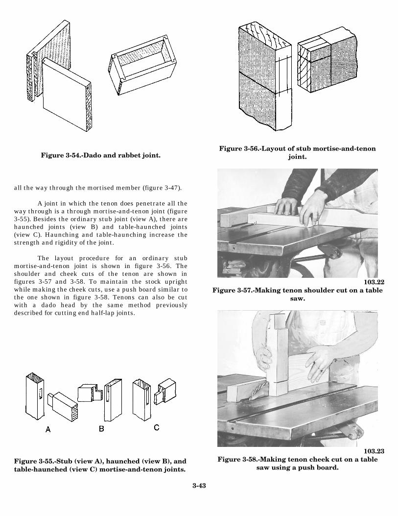
Figure 3-54.-Dado and rabbet joint.
all the way through the mortised member (figure 3-47).
A joint in which the tenon does penetrate all theway through is a through mortise-and-tenon joint (figure3-55). Besides the ordinary stub joint (view A), there arehaunched joints (view B) and table-haunched joints(view C). Haunching and table-haunching increase thestrength and rigidity of the joint.
The layout procedure for an ordinary stubmortise-and-tenon joint is shown in figure 3-56. Theshoulder and cheek cuts of the tenon are shown infigures 3-57 and 3-58. To maintain the stock uprightwhile making the cheek cuts, use a push board similar tothe one shown in figure 3-58. Tenons can also be cutwith a dado head by the same method previouslydescribed for cutting end half-lap joints.
Figure 3-55.-Stub (view A), haunched (view B), andtable-haunched (view C) mortise-and-tenon joints.
Figure 3-56.-Layout of stub mortise-and-tenonjoint.
103.22Figure 3-57.-Making tenon shoulder cut on a table
saw.
103.23Figure 3-58.-Making tenon cheek cut on a table
saw using a push board.
3-43
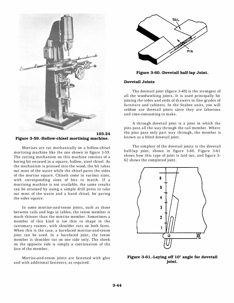
103.24Figure 3-59.-Hollow-chisel mortising machine.
Mortises are cut mechanically on a hollow-chiselmortising machine like the one shown in figure 3-59.The cutting mechanism on this machine consists of aboring bit encased in a square, hollow, steel chisel. Asthe mechanism is pressed into the wood, the bit takesout most of the waste while the chisel pares the sidesof the mortise square. Chisels come in various sizes,with corresponding sizes of bits to match. If amortising machine is not available, the same resultscan be attained by using a simple drill press to takeout most of the waste and a hand chisel, for paringthe sides square.
In some mortise-and-tenon joints, such as thosebetween rails and legs in tables, the tenon member ismuch thinner than the mortise member. Sometimes amember of this kind is too thin to shape in thecustomary reamer, with shoulder cuts on both faces.When this is the case, a barefaced mortise-and-tenonjoint can be used. In a barefaced joint, the tenonmember is shoulder cut on one side only. The cheekon the opposite side is simply a continuation of theface of the member.
Mortise-and-tenon joints are fastened with glueand with additional fasteners, as required.
Figure 3-60.-Dovetail half-lap Joint.
Dovetail Joints
The dovetail joint (figure 3-49) is the strongest ofall the woodworking joints. It is used principally forjoining the sides and ends of drawers in fine grades offurniture and cabinets. In the Seabee units, you willseldom use dovetail joints since they are laboriousand time-consuming to make.
A through dovetail joint is a joint in which thepins pass all the way through the tail member. Wherethe pins pass only part way through, the member isknown as a blind dovetail joint.
The simplest of the dovetail joints is the dovetailhalf-lap joint, shown in figure 3-60. Figure 3-61shows how this type of joint is laid out, and figure 3-62 shows the completed joint.
Figure 3-61.-Laying off 10° angle for dovetailjoint.
3-44
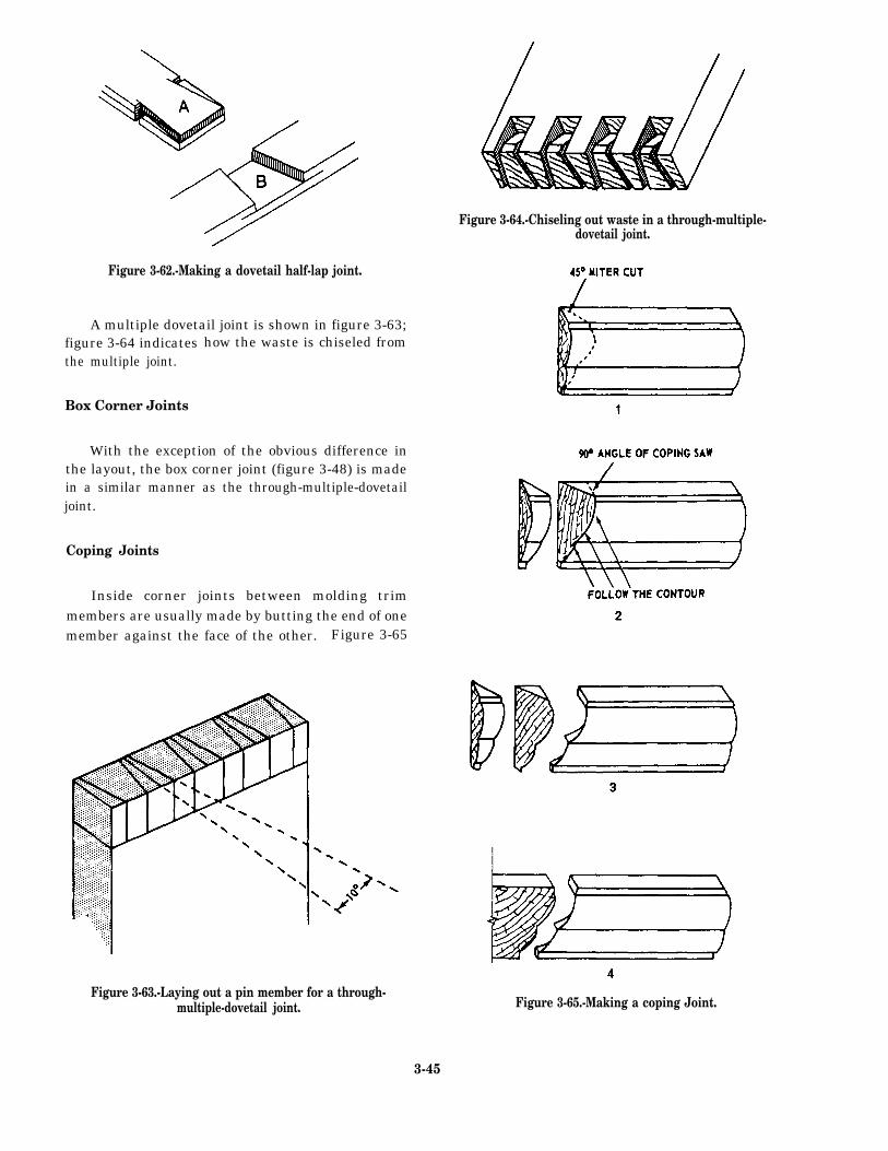
dovetail joint.
Figure 3-62.-Making a dovetail half-lap joint.
A multiple dovetail joint is shown in figure 3-63;figure 3-64 indicatesthe multiple joint.
Box Corner Joints
how the waste is chiseled from
With the exception of the obvious difference inthe layout, the box corner joint (figure 3-48) is madein a similar manner as the through-multiple-dovetailjoint.
Coping Joints
Inside corner joints between molding trimmembers are usually made by butting the end of onemember against the face of the other. Figure 3-65
Figure 3-63.-Laying out a pin member for a through-multiple-dovetail joint.
Figure 3-64.-Chiseling out waste in a through-multiple-
Figure 3-65.-Making a coping Joint.
3-45
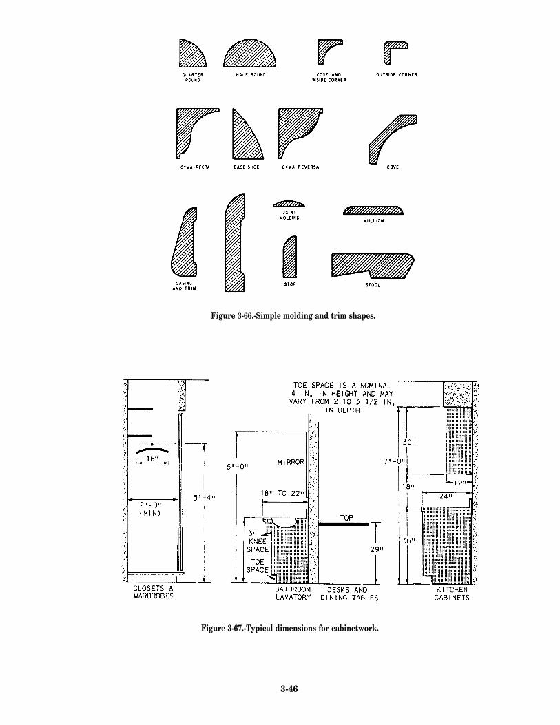
Figure 3-66.-Simple molding and trim shapes.
Figure 3-67.-Typical dimensions for cabinetwork.
3-46
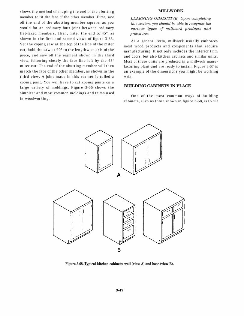
shows the method of shaping the end of the abuttingmember to tit the face of the other member. First, sawoff the end of the abutting member square, as youwould for an ordinary butt joint between ordinaryflat-faced members. Then, miter the end to 45°, asshown in the first and second views of figure 3-65.Set the coping saw at the top of the line of the mitercut, hold the saw at 90° to the lengthwise axis of thepiece, and saw off the segment shown in the thirdview, following closely the face line left by the 45°miter cut. The end of the abutting member will thenmatch the face of the other member, as shown in thethird view. A joint made in this reamer is called acoping joint. You will have to cut coping joints on alarge variety of moldings. Figure 3-66 shows thesimplest and most common moldings and trims usedin woodworking.
MILLWORK
LEARNING OBJECTIVE: Upon completingthis section, you should be able to recognize thevarious types of millwork products andprocedures.
As a general term, millwork usually embracesmost wood products and components that requiremanufacturing. It not only includes the interior trimand doors, but also kitchen cabinets and similar units.Most of these units are produced in a millwork manu-facturing plant and are ready to install. Figure 3-67 isan example of the dimensions you might be workingwith.
BUILDING CABINETS IN PLACE
One of the most common ways of buildingcabinets, such as those shown in figure 3-68, is to cut
Figure 3-68.-Typical kitchen cabinets: wall (view A) and base (view B).
3-47
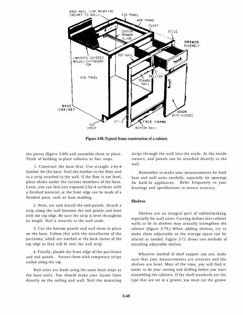
the pieces (figure 3-69) and assemble them in place.Think of building in-place cabinets in four steps.
1. Construct the base first. Use straight 2-by-4lumber for the base. Nail the lumber to the floor andto a strip attached to the wall. If the floor is not level,place shims under the various members of the base.Later, you can face any exposed 2-by-4 surfaces witha finished material, or the front edge can be made of afinished piece, such as base molding.
Figure 3-69.-Typical frame construction of a cabinet.
2. Next, cut and install the end panels. Attach astrip along the wall between the end panels and levelwith the top edge. Be sure the strip is level throughoutits length. Nail it securely to the wall studs.
3. Cut the bottom panels and nail them in placeon the base. Follow this with the installation of thepartitions, which are notched at the back corner of thetop edge so they will fit over the wall strip.
4. Finally, plumb the front edge of the partitionsand end panels. Secure them with temporary stripsnailed along the top.
Wall units are made using the same basic steps asthe base units. You should make your layout linesdirectly on the ceiling and wall. Nail the mounting
strips through the wall into the studs. At the insidecorners, end panels can be attached directly to thewall.
Remember to make your measurements for bothbase and wall units carefully, especially for openingsfor built-in appliances. Refer frequently to yourdrawings and specifications to ensure accuracy.
Shelves
Shelves are an integral part of cabinetmaking,especially for wall units. Cutting dadoes into cabinetwalls to fit in shelves may actually strengthen thecabinet (figure 3-70.) When adding shelves, try tomake them adjustable so the storage space can bealtered as needed. Figure 3-71 shows two methods ofinstalling adjustable shelves.
Whatever method of shelf support you use, makesure that your measurements are accurate and theshelves are level. Most of the time, you will find iteasier to do your cutting and drilling before you startassembling the cabinets. If the shelf standards are thetype that are set in a groove, you must cut the groove
3-48
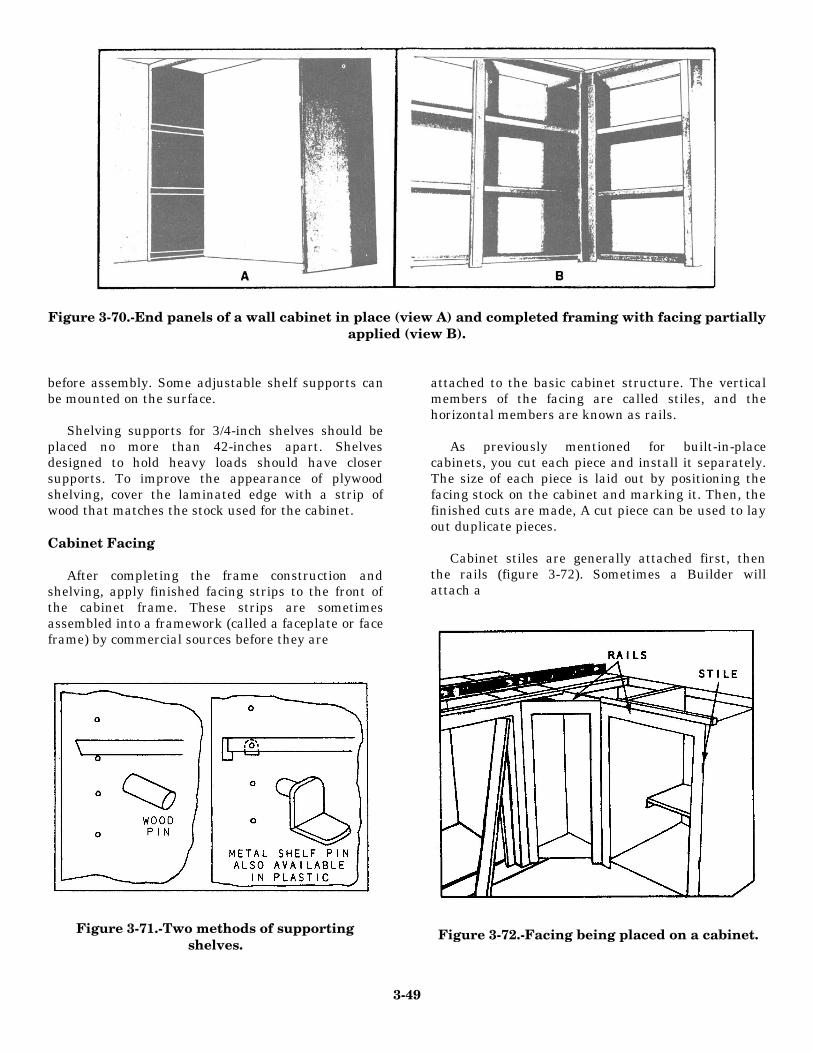
Figure 3-70.-End panels of a wall cabinet in place (view A) and completed framing with facing partiallyapplied (view B).
before assembly. Some adjustable shelf supports canbe mounted on the surface.
Shelving supports for 3/4-inch shelves should beplaced no more than 42-inches apart. Shelvesdesigned to hold heavy loads should have closersupports. To improve the appearance of plywoodshelving, cover the laminated edge with a strip ofwood that matches the stock used for the cabinet.
Cabinet Facing
After completing the frame construction andshelving, apply finished facing strips to the front ofthe cabinet frame. These strips are sometimesassembled into a framework (called a faceplate or faceframe) by commercial sources before they are
Figure 3-71.-Two methods of supportingshelves.
attached to the basic cabinet structure. The verticalmembers of the facing are called stiles, and thehorizontal members are known as rails.
As previously mentioned for built-in-placecabinets, you cut each piece and install it separately.The size of each piece is laid out by positioning thefacing stock on the cabinet and marking it. Then, thefinished cuts are made, A cut piece can be used to layout duplicate pieces.
Cabinet stiles are generally attached first, thenthe rails (figure 3-72). Sometimes a Builder willattach a
Figure 3-72.-Facing being placed on a cabinet.
3-49
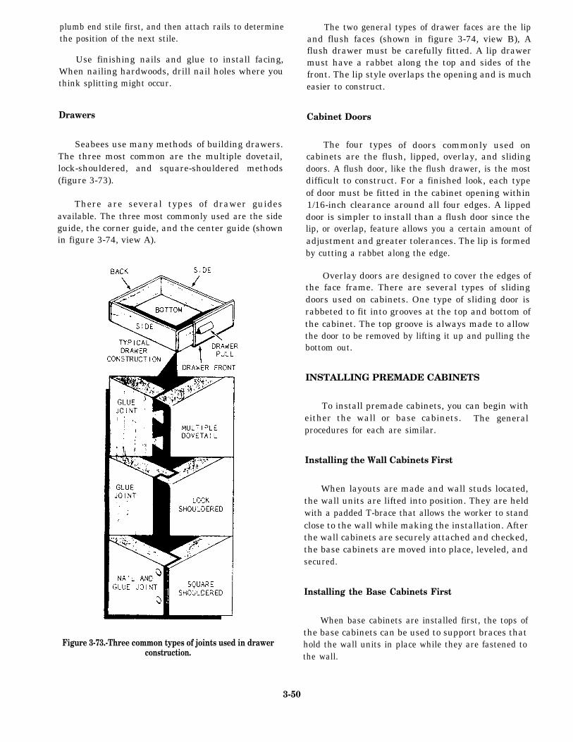
plumb end stile first, and then attach rails to determinethe position of the next stile.
Use finishing nails and glue to install facing,When nailing hardwoods, drill nail holes where youthink splitting might occur.
Drawers
Seabees use many methods of building drawers.The three most common are the multiple dovetail,lock-shouldered, and square-shouldered methods(figure 3-73).
There are several types of drawer guidesavailable. The three most commonly used are the sideguide, the corner guide, and the center guide (shownin figure 3-74, view A).
The two general types of drawer faces are the lipand flush faces (shown in figure 3-74, view B), Aflush drawer must be carefully fitted. A lip drawermust have a rabbet along the top and sides of thefront. The lip style overlaps the opening and is mucheasier to construct.
Cabinet Doors
The four types of doors commonly used oncabinets are the flush, lipped, overlay, and slidingdoors. A flush door, like the flush drawer, is the mostdifficult to construct. For a finished look, each typeof door must be fitted in the cabinet opening within1/16-inch clearance around all four edges. A lippeddoor is simpler to install than a flush door since thelip, or overlap, feature allows you a certain amount ofadjustment and greater tolerances. The lip is formedby cutting a rabbet along the edge.
Overlay doors are designed to cover the edges ofthe face frame. There are several types of slidingdoors used on cabinets. One type of sliding door israbbeted to fit into grooves at the top and bottom ofthe cabinet. The top groove is always made to allowthe door to be removed by lifting it up and pulling thebottom out.
Figure 3-73.-Three common types of joints used in drawerconstruction.
INSTALLING PREMADE CABINETS
To install premade cabinets, you can begin witheither the wall or base cabinets. The generalprocedures for each are similar.
Installing the Wall Cabinets First
When layouts are made and wall studs located,the wall units are lifted into position. They are heldwith a padded T-brace that allows the worker to standclose to the wall while making the installation. Afterthe wall cabinets are securely attached and checked,the base cabinets are moved into place, leveled, andsecured.
Installing the Base Cabinets First
When base cabinets are installed first, the tops ofthe base cabinets can be used to support braces thathold the wall units in place while they are fastened tothe wall.
3-50
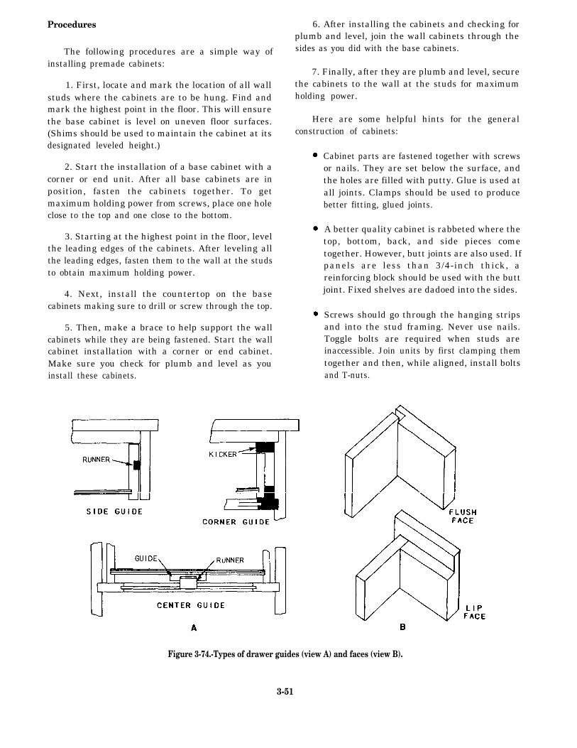
Procedures
The following procedures are a simple way ofinstalling premade cabinets:
1. First, locate and mark the location of all wallstuds where the cabinets are to be hung. Find andmark the highest point in the floor. This will ensurethe base cabinet is level on uneven floor surfaces.(Shims should be used to maintain the cabinet at itsdesignated leveled height.)
2. Start the installation of a base cabinet with acorner or end unit. After all base cabinets are inposition, fasten the cabinets together. To getmaximum holding power from screws, place one holeclose to the top and one close to the bottom.
3. Starting at the highest point in the floor, levelthe leading edges of the cabinets. After leveling allthe leading edges, fasten them to the wall at the studsto obtain maximum holding power.
4. Next, install the countertop on the basecabinets making sure to drill or screw through the top.
5. Then, make a brace to help support the wallcabinets while they are being fastened. Start the wallcabinet installation with a corner or end cabinet.Make sure you check for plumb and level as youinstall these cabinets.
6. After installing the cabinets and checking forplumb and level, join the wall cabinets through thesides as you did with the base cabinets.
7. Finally, after they are plumb and level, securethe cabinets to the wall at the studs for maximumholding power.
Here are some helpful hints for the generalconstruction of cabinets:
Cabinet parts are fastened together with screwsor nails. They are set below the surface, andthe holes are filled with putty. Glue is used atall joints. Clamps should be used to producebetter fitting, glued joints.
A better quality cabinet is rabbeted where thetop, bottom, back, and side pieces cometogether. However, butt joints are also used. Ifpanels are less than 3/4-inch thick, areinforcing block should be used with the buttjoint. Fixed shelves are dadoed into the sides.
Screws should go through the hanging stripsand into the stud framing. Never use nails.Toggle bolts are required when studs areinaccessible. Join units by first clamping themtogether and then, while aligned, install boltsand T-nuts.
Figure 3-74.-Types of drawer guides (view A) and faces (view B).
3-51
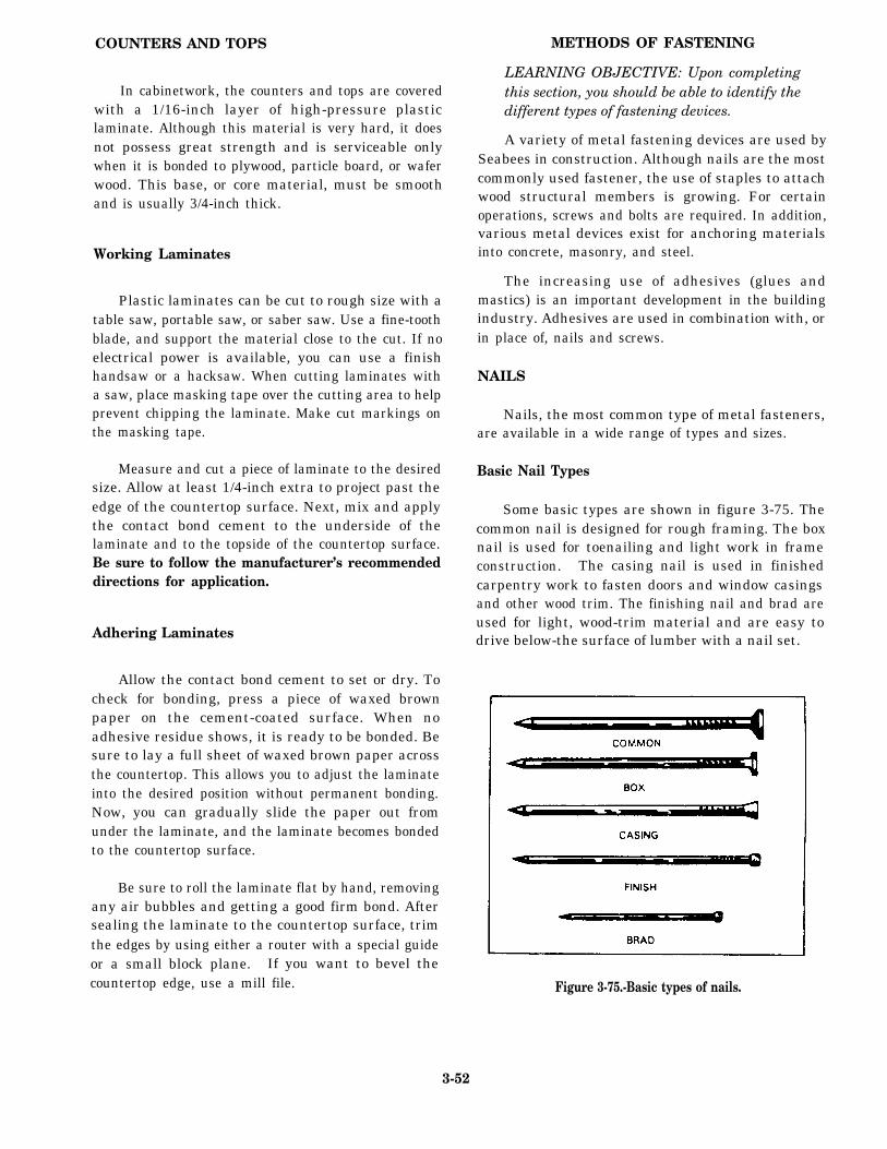
COUNTERS AND TOPS
In cabinetwork, the counters and tops are coveredwith a 1/16-inch layer of high-pressure plasticlaminate. Although this material is very hard, it doesnot possess great strength and is serviceable onlywhen it is bonded to plywood, particle board, or waferwood. This base, or core material, must be smoothand is usually 3/4-inch thick.
Working Laminates
Plastic laminates can be cut to rough size with atable saw, portable saw, or saber saw. Use a fine-toothblade, and support the material close to the cut. If noelectrical power is available, you can use a finishhandsaw or a hacksaw. When cutting laminates witha saw, place masking tape over the cutting area to helpprevent chipping the laminate. Make cut markings onthe masking tape.
Measure and cut a piece of laminate to the desiredsize. Allow at least 1/4-inch extra to project past theedge of the countertop surface. Next, mix and applythe contact bond cement to the underside of thelaminate and to the topside of the countertop surface.Be sure to follow the manufacturer’s recommendeddirections for application.
Adhering Laminates
Allow the contact bond cement to set or dry. Tocheck for bonding, press a piece of waxed brownpaper on the cement-coated surface. When noadhesive residue shows, it is ready to be bonded. Besure to lay a full sheet of waxed brown paper acrossthe countertop. This allows you to adjust the laminateinto the desired position without permanent bonding.Now, you can gradually slide the paper out fromunder the laminate, and the laminate becomes bondedto the countertop surface.
Be sure to roll the laminate flat by hand, removingany air bubbles and getting a good firm bond. Aftersealing the laminate to the countertop surface, trimthe edges by using either a router with a special guideor a small block plane. If you want to bevel thecountertop edge, use a mill file.
METHODS OF FASTENING
LEARNING OBJECTIVE: Upon completingthis section, you should be able to identify thedifferent types of fastening devices.
A variety of metal fastening devices are used bySeabees in construction. Although nails are the mostcommonly used fastener, the use of staples to attachwood structural members is growing. For certainoperations, screws and bolts are required. In addition,various metal devices exist for anchoring materialsinto concrete, masonry, and steel.
The increasing use of adhesives (glues andmastics) is an important development in the buildingindustry. Adhesives are used in combination with, orin place of, nails and screws.
NAILS
Nails, the most common type of metal fasteners,are available in a wide range of types and sizes.
Basic Nail Types
Some basic types are shown in figure 3-75. Thecommon nail is designed for rough framing. The boxnail is used for toenailing and light work in frameconstruction. The casing nail is used in finishedcarpentry work to fasten doors and window casingsand other wood trim. The finishing nail and brad areused for light, wood-trim material and are easy todrive below-the surface of lumber with a nail set.
Figure 3-75.-Basic types of nails.
3-52
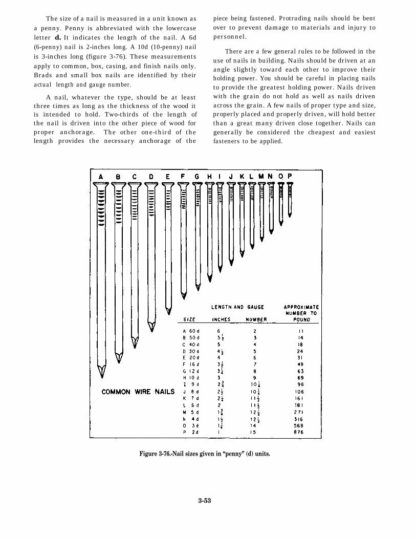
The size of a nail is measured in a unit known asa penny. Penny is abbreviated with the lowercaseletter d. It indicates the length of the nail. A 6d(6-penny) nail is 2-inches long. A 10d (10-penny) nailis 3-inches long (figure 3-76). These measurementsapply to common, box, casing, and finish nails only.Brads and small box nails are identified by theiractual length and gauge number.
A nail, whatever the type, should be at leastthree times as long as the thickness of the wood itis intended to hold. Two-thirds of the length ofthe nail is driven into the other piece of wood forproper anchorage. The other one-third of thelength provides the necessary anchorage of the
piece being fastened. Protruding nails should be bentover to prevent damage to materials and injury topersonnel.
There are a few general rules to be followed in theuse of nails in building. Nails should be driven at anangle slightly toward each other to improve theirholding power. You should be careful in placing nailsto provide the greatest holding power. Nails drivenwith the grain do not hold as well as nails drivenacross the grain. A few nails of proper type and size,properly placed and properly driven, will hold betterthan a great many driven close together. Nails cangenerally be considered the cheapest and easiestfasteners to be applied.
Figure 3-76.-Nail sizes given in “penny” (d) units.
3-53
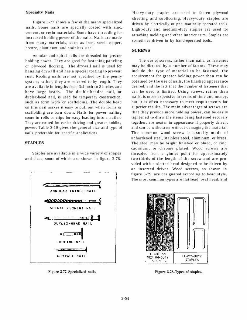
Specialty Nails
Figure 3-77 shows a few of the many specializednails. Some nails are specially coated with zinc,cement, or resin materials. Some have threading forincreased holding power of the nails. Nails are madefrom many materials, such as iron, steel, copper,bronze, aluminum, and stainless steel.
Annular and spiral nails are threaded for greaterholding power. They are good for fastening panelingor plywood flooring. The drywall nail is used forhanging drywall and has a special coating to preventrust. Roofing nails are not specified by the pennysystem; rather, they are referred to by length. Theyare available in lengths from 3/4 inch to 2 inches andhave large heads. The double-headed nail, orduplex-head nail, is used for temporary construction,such as form work or scaffolding. The double headon this nail makes it easy to pull out when forms orscaffolding are torn down. Nails for power nailingcome in rolls or clips for easy loading into a nailer.They are coated for easier driving and greater holdingpower. Table 3-10 gives the general size and type ofnails preferable for specific applications.
STAPLES
Staples are available in a wide variety of shapesand sizes, some of which are shown in figure 3-78.
Heavy-duty staples are used to fasten plywoodsheeting and subflooring. Heavy-duty staples aredriven by electrically or pneumatically operated tools.Light-duty and medium-duty staples are used forattaching molding and other interior trim. Staples aresometimes driven in by hand-operated tools.
SCREWS
The use of screws, rather than nails, as fastenersmay be dictated by a number of factors. These mayinclude the type of material to be fastened, therequirement for greater holding power than can beobtained by the use of nails, the finished appearancedesired, and the fact that the number of fasteners thatcan be used is limited. Using screws, rather thannails, is more expensive in terms of time and money,but it is often necessary to meet requirements forsuperior results. The main advantages of screws arethat they provide more holding power, can be easilytightened to draw the items being fastened securelytogether, are neater in appearance if properly driven,and can be withdrawn without damaging the material.The common wood screw is usually made ofunhardened steel, stainless steel, aluminum, or brass.The steel may be bright finished or blued, or zinc,cadmium, or chrome plated. Wood screws arethreaded from a gimlet point for approximatelytwo-thirds of the length of the screw and are pro-vided with a slotted head designed to be driven byan inserted driver. Wood screws, as shown infigure 3-79, are designated according to head style.The most common types are flathead, oval head, and
Figure 3-77.-Specialized nails. Figure 3-78.-Types of staples.
3-54

Table 3-10.-Size, Type, and Use of Nails
3 -55
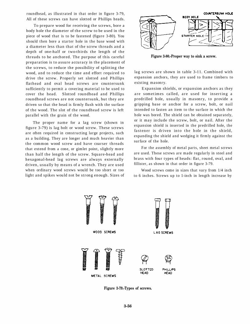
roundhead, as illustrated in that order in figure 3-79,All of these screws can have slotted or Phillips heads.
To prepare wood for receiving the screws, bore abody hole the diameter of the screw to be used in thepiece of wood that is to be fastened (figure 3-80). Youshould then bore a starter hole in the base wood witha diameter less than that of the screw threads and adepth of one-half or two-thirds the length of thethreads to be anchored. The purpose of this carefulpreparation is to assure accuracy in the placement ofthe screws, to reduce the possibility of splitting thewood, and to reduce the time and effort required todrive the screw. Properly set slotted and Phillipsflathead and oval head screws are countersunksufficiently to permit a covering material to be used tocover the head. Slotted roundhead and Phillipsroundhead screws are not countersunk, but they aredriven so that the head is firmly flush with the surfaceof the wood. The slot of the roundhead screw is leftparallel with the grain of the wood.
The proper name for a lag screw (shown infigure 3-79) is lag bolt or wood screw. These screwsare often required in constructing large projects, suchas a building. They are longer and much heavier thanthe common wood screw and have coarser threadsthat extend from a cone, or gimlet point, slightly morethan half the length of the screw. Square-head andhexagonal-head lag screws are always externallydriven, usually by means of a wrench. They are usedwhen ordinary wood screws would be too short or toolight and spikes would not be strong enough. Sizes of
Figure 3-80.-Proper way to sink a screw.
lag screws are shown in table 3-11. Combined withexpansion anchors, they are used to frame timbers toexisting masonry.
Expansion shields, or expansion anchors as theyare sometimes called, are used for inserting apredrilled hole, usually in masonry, to provide agripping base or anchor for a screw, bolt, or nailintended to fasten an item to the surface in which thehole was bored. The shield can be obtained separately,or it may include the screw, bolt, or nail. After theexpansion shield is inserted in the predrilled hole, thefastener is driven into the hole in the shield,expanding the shield and wedging it firmly against thesurface of the hole.
For the assembly of metal parts, sheet metal screwsare used. These screws are made regularly in steel andbrass with four types of heads: flat, round, oval, andfillister, as shown in that order in figure 3-79.
Wood screws come in sizes that vary from 1/4 inchto 6 inches. Screws up to 1-inch in length increase by
Figure 3-79.-Types of screws.
3-56
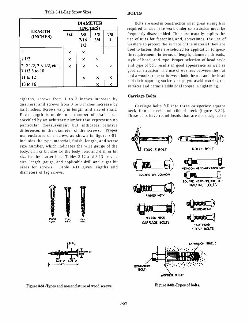
Table 3-11.-Lag Screw Sizes
eighths, screws from 1 to 3 inches increase byquarters, and screws from 3 to 6 inches increase byhalf inches. Screws vary in length and size of shaft.Each length is made in a number of shaft sizesspecified by an arbitrary number that represents noparticular measurement but indicates relativedifferences in the diameter of the screws. Propernomenclature of a screw, as shown in figure 3-81,includes the type, material, finish, length, and screwsize number, which indicates the wire gauge of thebody, drill or bit size for the body hole, and drill or bitsize for the starter hole. Tables 3-12 and 3-13 providesize, length, gauge, and applicable drill and auger bitsizes for screws. Table 3-11 gives lengths anddiameters of lag screws.
Figure 3-81.-Types and nomenclature of wood screws.
BOLTS
Bolts are used in construction when great strength isrequired or when the work under construction must befrequently disassembled. Their use usually implies theuse of nuts for fastening and, sometimes, the use ofwashers to protect the surface of the material they areused to fasten. Bolts are selected for application to speci-fic requirements in terms of length, diameter, threads,style of head, and type. Proper selection of head styleand type of bolt results in good appearance as well asgood construction. The use of washers between the nutand a wood surface or between both the nut and the headand their opposing surfaces helps you avoid marring thesurfaces and permits additional torque in tightening.
Carriage Bolts
Carriage bolts fall into three categories: squareneck finned neck and ribbed neck (figure 3-82).These bolts have round heads that are not designed to
Figure 3-82.-Types of bolts.
3-57
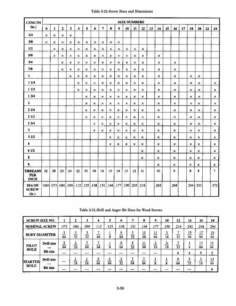
Table 3-12.-Screw Sizes and Dimensions
Table 3-13.-Drill and Auger Bit Sizes for Wood Screws
3-58
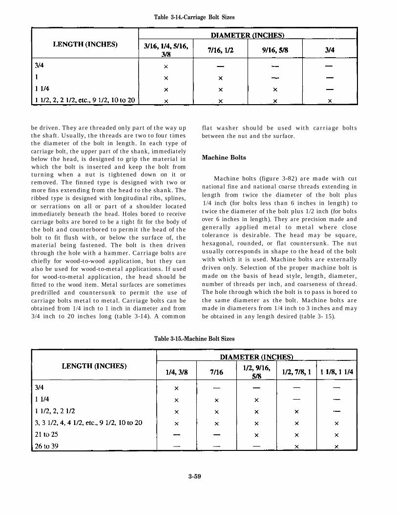
Table 3-14.-Carriage Bolt Sizes
be driven. They are threaded only part of the way upthe shaft. Usually, the threads are two to four timesthe diameter of the bolt in length. In each type ofcarriage bolt, the upper part of the shank, immediatelybelow the head, is designed to grip the material inwhich the bolt is inserted and keep the bolt fromturning when a nut is tightened down on it orremoved. The finned type is designed with two ormore fins extending from the head to the shank. Theribbed type is designed with longitudinal ribs, splines,or serrations on all or part of a shoulder locatedimmediately beneath the head. Holes bored to receivecarriage bolts are bored to be a tight fit for the body ofthe bolt and counterbored to permit the head of thebolt to fit flush with, or below the surface of, thematerial being fastened. The bolt is then driventhrough the hole with a hammer. Carriage bolts arechiefly for wood-to-wood application, but they canalso be used for wood-to-metal applications. If usedfor wood-to-metal application, the head should befitted to the wood item. Metal surfaces are sometimespredrilled and countersunk to permit the use ofcarriage bolts metal to metal. Carriage bolts can beobtained from 1/4 inch to 1 inch in diameter and from3/4 inch to 20 inches long (table 3-14). A common
flat washer should be used with carriage boltsbetween the nut and the surface.
Machine Bolts
Machine bolts (figure 3-82) are made with cutnational fine and national coarse threads extending inlength from twice the diameter of the bolt plus1/4 inch (for bolts less than 6 inches in length) totwice the diameter of the bolt plus 1/2 inch (for boltsover 6 inches in length). They are precision made andgenerally applied metal to metal where closetolerance is desirable. The head may be square,hexagonal, rounded, or flat countersunk. The nutusually corresponds in shape to the head of the boltwith which it is used. Machine bolts are externallydriven only. Selection of the proper machine bolt ismade on the basis of head style, length, diameter,number of threads per inch, and coarseness of thread.The hole through which the bolt is to pass is bored tothe same diameter as the bolt. Machine bolts aremade in diameters from 1/4 inch to 3 inches and maybe obtained in any length desired (table 3- 15).
Table 3-15.-Machine Bolt Sizes
3-59
Stove Bolts
Stove bolts (figure 3-82) are less precisely madethan machine bolts. They are made with either flat orround slotted heads and may have threads extendingover the full length of the body, over part of the body,or over most of the body. They are generally usedwith square nuts and applied metal to metal, wood towood, or wood to metal. If flatheaded, they arecountersunk. If roundheaded, they are drawn flush tothe surface.
Expansion Bolt
An expansion bolt (figure 3-82) is a bolt used inconjunction with an expansion shield to provideanchorage in substances in which a threaded fasteneralone is useless. The shield, or expansion anchor, isinserted in a predrilled hole and expands when thebolt is driven into it. It becomes wedged firmly in thehole, providing a secure base for the grip of thefastener.
Toggle Bolts
A toggle bolt (figure 3-82) is a machine screwwith a spring-action, wing-head nut that folds back asthe entire assembly is pushed through a prepared holein a hollow wall. The wing head then springs openinside the wall cavity. As the screw is tightened, thewing head is drawn against the inside surface of thefinished wall material. Spring-action, wing-headtoggle bolts are available in a variety of machinescrew combinations. Common sizes range from 1/8inch to 3/8 inch in diameter and 2 inches to 6 inches inlength. They are particularly useful with sheetrockwall surfaces.
Molly Bolt
The molly bolt or molly expansion anchor(figure 3-82) is used to fasten small cabinets, towelbars, drapery hangers, mirrors, electrical fixtures, andother lightweight items to hollow walls. It is insertedin a prepared hole. Prongs on the outside of the shieldgrip the wall surfaces to prevent the shield fromturning as the anchor screw is being driven. As thescrew is tightened, the shield spreads and flattensagainst the interior of the wall. Various sizes of screwanchors can be used in hollow walls 1/8 inch to 1 3/4inches thick.
Figure 3-83.-Driftpin (driftbolt).
Driftpins
Driftpins are long, heavy, threadless bolts used tohold heavy pieces of timber together (figure 3-83).They have heads that vary in diameter from 1/2 to1 inch and in length from 18 to 26 inches. The term“driftpin” is almost universally used in practice.However, for supply purposes, the correct designationis driftbolt.
To use the driftpin, you make a hole slightlysmaller than the diameter of the pin in the timber. Thepin is driven into the hole and is held in place by thecompression action of the wood fibers.
CORRUGATED FASTENERS
The corrugated fastener is one of the many meansby which joints and splices are fastened in smalltimber and boards. It is used particularly in the miterjoint. Corrugated fasteners are made of 18- to22-gauge sheet metal with alternate ridges andgrooves; the ridges vary from 3/16 to 5/ 16 inch, centerto center. One end is cut square; the other end issharpened with beveled edges. There are two types ofcorrugated fasteners: one with the ridges runningparallel (figure 3-84, view A); the other with ridgesrunning at a slight angle to one another (figure 3-84,view B), The latter type has a tendency to compressthe material since the ridges and grooves are closer atthe top than at the bottom. These fasteners are madein several different lengths and widths. The widthvaries from 5/8 to 1 1/8 inches; the length varies from1/4 to 3/4 inch. The fasteners also are made withdifferent numbers of ridges, ranging from three to sixridges per fastener. Corrugated fasteners are used in anumber of ways—to fasten parallel boards together,as in fastening tabletops; to make any type of joint;and as a substitute for nails where nails may split thetimber. In small timber, corrugated fasteners havegreater holding power than nails. The proper methodof using the fasteners is shown in figure 3-84.
ADHESIVES
Seabees use many different types of adhesives invarious phases of their construction projects. Glues
3-60
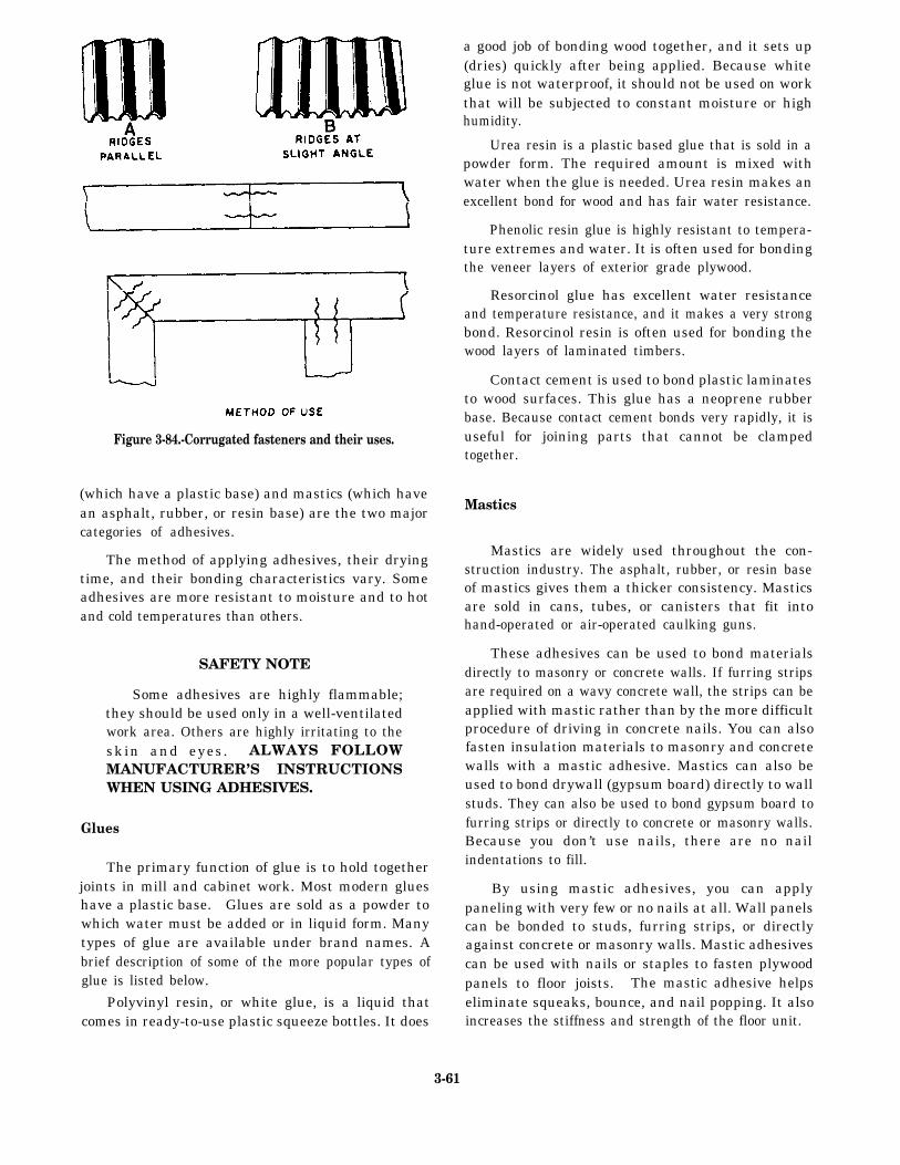
Figure 3-84.-Corrugated fasteners and their uses.
(which have a plastic base) and mastics (which havean asphalt, rubber, or resin base) are the two majorcategories of adhesives.
The method of applying adhesives, their dryingtime, and their bonding characteristics vary. Someadhesives are more resistant to moisture and to hotand cold temperatures than others.
SAFETY NOTE
Some adhesives are highly flammable;they should be used only in a well-ventilatedwork area. Others are highly irritating to theskin and eyes. ALWAYS FOLLOWMANUFACTURER’S INSTRUCTIONSWHEN USING ADHESIVES.
Glues
The primary function of glue is to hold togetherjoints in mill and cabinet work. Most modern glueshave a plastic base. Glues are sold as a powder towhich water must be added or in liquid form. Manytypes of glue are available under brand names. Abrief description of some of the more popular types ofglue is listed below.
Polyvinyl resin, or white glue, is a liquid thatcomes in ready-to-use plastic squeeze bottles. It does
a good job of bonding wood together, and it sets up(dries) quickly after being applied. Because whiteglue is not waterproof, it should not be used on workthat will be subjected to constant moisture or highhumidity.
Urea resin is a plastic based glue that is sold in apowder form. The required amount is mixed withwater when the glue is needed. Urea resin makes anexcellent bond for wood and has fair water resistance.
Phenolic resin glue is highly resistant to tempera-ture extremes and water. It is often used for bondingthe veneer layers of exterior grade plywood.
Resorcinol glue has excellent water resistanceand temperature resistance, and it makes a very strongbond. Resorcinol resin is often used for bonding thewood layers of laminated timbers.
Contact cement is used to bond plastic laminatesto wood surfaces. This glue has a neoprene rubberbase. Because contact cement bonds very rapidly, it isuseful for joining parts that cannot be clampedtogether.
Mastics
Mastics are widely used throughout the con-struction industry. The asphalt, rubber, or resin baseof mastics gives them a thicker consistency. Masticsare sold in cans, tubes, or canisters that fit intohand-operated or air-operated caulking guns.
These adhesives can be used to bond materialsdirectly to masonry or concrete walls. If furring stripsare required on a wavy concrete wall, the strips can beapplied with mastic rather than by the more difficultprocedure of driving in concrete nails. You can alsofasten insulation materials to masonry and concretewalls with a mastic adhesive. Mastics can also beused to bond drywall (gypsum board) directly to wallstuds. They can also be used to bond gypsum board tofurring strips or directly to concrete or masonry walls.Because you don’t use nails, there are no nailindentations to fill.
By using mastic adhesives, you can applypaneling with very few or no nails at all. Wall panelscan be bonded to studs, furring strips, or directlyagainst concrete or masonry walls. Mastic adhesivescan be used with nails or staples to fasten plywoodpanels to floor joists. The mastic adhesive helpseliminate squeaks, bounce, and nail popping. It alsoincreases the stiffness and strength of the floor unit.
3-61

RECOMMENDED READING LIST You therefore need to ensure that you arestudying the latest revision.
NOTE Carpentry I, Headquarters, EN5155, U.S. ArmyEngineering School, Fort Belvoir, Va., 1988.
Although the following references werecurrent when this TRAMAN was published, Carpentry III, Headquarters, EN0533, U.S. Armytheir continued currency cannot be assured. Engineering School, Fort Belvoir, Va., 1987.
3-62