Embed Size (px)
Citation preview

WLAN 802.11n: From SISO to MIMO Application Note
Products:
| R&SSMW200A
| R&SSMU200A
| R&SAMU200A
| R&SSMJ100A
| R&SSMBV100A
| R&SSMATE200A
| R&SFSQ
| R&SFSV
| R&SCMW270
| R&SCMW500
New wireless applications demand ever increasing data rates from both cellular and non-cellular networks. To satisfy these needs in non-cellular networks, the IEEE 802.11 (WLAN) standard - the most commonly used standard for wireless local area networks today - is continually being extended. This application note discusses WLAN standard IEEE 802.11n. It first describes the most important amendments to previous releases and the ambitious new measurement tasks. Then, it describes how to deal with these tasks using Rohde & Schwarz instruments. The main focus here is on transmission over several TX and RX antennas (MIMO). Building multistandard signals using Rohde & Schwarz generators is also described. Screenshots from the analyzer taken on 802.11n signals complete the document.
App
licat
ion
Not
e
Det
lev
Lieb
l
04_2
011
- 1M
A17
9_10
e
Table of Contents
1MA179_10e Rohde & Schwarz WLAN 802.11n: From SISO to MIMO 2
Table of Contents
1 Overview ................................................................................. 3
2 Amendments to the Physical Layer...................................... 4
3 IEEE 802.11n Tests ................................................................ 7
4 Principles of MIMO Testing ................................................. 10
5 Generating MIMO Signals.................................................... 15
5.1 Common WLAN Settings...........................................................................16
5.2 Instrument-Specific Setups.......................................................................23
6 Generating WLAN Multistandard Signals .......................... 33
7 Analyzing MIMO Signals...................................................... 34
7.1 Radio Communication Tester ...................................................................34
7.2 Vector Signal Analyzer ..............................................................................37
7.3 Measurement Results ................................................................................44
8 Summary............................................................................... 55
9 Literature............................................................................... 55
10 Additional Information......................................................... 56
11 Ordering Information ........................................................... 57

Overview
Common WLAN Settings
1MA179_10e Rohde & Schwarz WLAN 802.11n: From SISO to MIMO 3
1 Overview New wireless applications demand ever increasing data rates from both cellular and non-cellular networks. To satisfy these needs in non-cellular networks, the IEEE 802.11 (WLAN) standard - the most commonly used standard for wireless local area networks today - is continually being extended. For the WLAN products of today and tomorrow, Rohde & Schwarz generators, analyzers, and radiocommunications testers offer very easy-to-use measurements for IEEE standards 802.11 a,b,g, and n, permitting efficient testing of chips, modules and devices. Rohde & Schwarz provides test equipment suitable for both R&D and production. This application note discusses WLAN standard IEEE 802.11n. It first describes the most important amendments to previous releases and the ambitious new measurement tasks. Then, it describes how to deal with these tasks using Rohde & Schwarz instruments. The main focus here is on transmission over several TX and RX antennas (MIMO). Building multistandard signals using Rohde & Schwarz generators is also described. Screenshots from the analyzer taken on 802.11n signals complete the document. Rohde & Schwarz continually implement new additional features and functions into their T&M instruments. This application note therefore reflects only the current situation. The following instruments are mentioned: Vector Signal Generators: ● R&S®SMW200A (referred to as SMW) Firmware 3.01.009.04 or later ● R&S®SMU200A (referred to as SMU) Firmware 2.10.111.153 or later ● R&S®AMU200A (referred to as AMU) Firmware 2.10.111.153 or later ● R&S®SMATE200A (referred to as SMATE) Firmware 2.10.111.153 or later ● R&S®SMJ100A (referred to as SMJ) Firmware 2.10.111.153 or later ● R&S®SMBV100A (referred to as SMBV) Firmware 2.15.085.78 or later Signal Analyzers: ● R&S®FSQ (referred to as FSQ) Firmware 4.65 SP1 or later ● R&S®FSV (referred to as FSV) Firmware 1.70 or later Wideband Connectivity Tester: ● R&S®CMW270 (referred to as CMW) Firmware 2.0.20 or later Wideband Radio Communication Tester: ● R&S®CMW500 (referred to as CMW) Firmware 2.0.20 or later Simulation Software: ● R&S®WinIQSIM2TM (referred to as WinIQSIM2) Version 2.10.111.91 or later

Amendments to the Physical Layer
Common WLAN Settings
1MA179_10e Rohde & Schwarz WLAN 802.11n: From SISO to MIMO 4
2 Amendments to the Physical Layer In order to bring about a significant increase in data throughput, IEEE 802.11-2007 has been expanded in 2009 to include Amendment 5, creating IEEE 802.11n. Amendment 5 contains the new Clause 20, which specifies the high throughput physical layer (HT PHY). In contrast to WLAN stations (STA) as defined in IEEE standard 802.11b, a, or g, high throughput stations (HT STA) have a number of additional attributes in the physical (PHY) and medium access (MAC) layers. The most significant are: New packet formats (PCLP physical data unit [PPDU] formats) New TX modes, 20 MHz and 40 MHz transmission bandwidth New modulation and coding schemes (MCS) Frame aggregation in the MAC; the maximum length of a physical data unit is 65535 octets Multiple input, multiple output (MIMO), with spatial multiplexing, space-time block coding (STBC), and spatial mapping These measures increase the data rate up to 600 Mbps. Fig. 1 shows the packet formats used for WLAN 802.11n:
Fig. 1: Packet formats for IEEE 802.11n.
The 802.11 a/g format, also called the legacy format, cannot provide any higher throughput. Legacy frames are included exclusively for maintaining backward compatibility with IEEE 802.11 a/g. The HT mixed format includes the legacy elements short training field (L-STF), long training field (L-LTF), and signal field (L-SIG) in the header. This ensures compatibility between the HT mixed frame and the IEEE 802.11 a/g standard. Its expanded modulation and coding schemes (MCS) permit significant increases in throughput. The new HT greenfield format is not compatible with the legacy mode. This format permits the highest data rates. IEEE 802.11n uses OFDM like IEEE 802.11a/g. In 20 MHz mode, there are 64 subcarriers (like for IEEE 802.11 a/g), while there are 128 subcarriers in 40 MHz mode. Table 1 shows the TX modes specified in IEEE 802.11n and the frequency spectrum used by Legacy mode, Mixed mode, and Greenfield mode.

Amendments to the Physical Layer
Common WLAN Settings
1MA179_10e Rohde & Schwarz WLAN 802.11n: From SISO to MIMO 5
Table 1: TX modes and bandwidths.
Another new feature is channel sounding. This feature adds one or more enhanced training fields to the PPDU; these can help to improve the radio channel estimation. In L-duplicate mode, the upper channel is rotated by +90° relative to the lower channel. (This can be easily achieved by the I/Q Swap function of the R&S generators.) T&M instruments intended for testing 802.11n stations are faced with great challenges. One lies in the variety of new signals to be generated and analyzed. (At present, there are 77 modulation and coding schemes.) A second challenge lies in the new demands that the MIMO technology places on test equipment. Where before only one TX signal had to be measured or only one RX signal generated, the test equipment must now process up to four RF signals (chains) simultaneously. One significant factor is whether only production tests are required, or whether the instrument will have to handle detailed and complex R&D test sequences. With their advanced WLAN options, Rohde & Schwarz instruments cope very easily with the IEEE 802.11n enhancements. The CMW radio communication tester is an optimal, cost-effective solution for production environment. The AMU, SMATE, SMU, and SMBV generators and the FSQ / FSV analyzers are available for use in both R&D and production. Generators and analyzers can be cascaded as needed so that the test setup adapts to the task. IEEE 802.11 is intended for use with a wide range of instruments. Unlike routers, for example, the limited space on WLAN USB sticks can barely hold four antennas for 4x MIMO. The price pressure associated with low-cost devices requires that producers implement only a minimum of functions. The power consumption often determines which functions are included. For these reasons, IEEE 802.11n makes some features mandatory, while others are optional. Table 2 provides an overview of the properties:

Amendments to the Physical Layer
Common WLAN Settings
1MA179_10e Rohde & Schwarz WLAN 802.11n: From SISO to MIMO 6
Properties Mandatory Optional
Legacy format, compatible to a, b, g x
HT Mixed format x
HT Greenfield format x
20 MHz: up to 4 spatial streams x
40 MHz: up to 4 spatial streams x
BPSK, QPSK, 16QAM, 64QAM x
Forward error correction convolutional coding (FEC) x
Low density parity check coding (LDPC) x
400 ns short guard interval (TX and RX) x
Beamforming x
Space-time block coding (STBC) x
HT non AP: all equal modulation rates for one spatial stream (MCS 0 through 7) using 20 MHz bandwidth
x
HT AP: all equal modulation rates for one and two spatial streams (MCS 0 through 15) using 20 MHz bandwidth
x
Table 2: Mandatory and optional features of IEEE 802.11n. Rohde & Schwarz instruments support all mandatory and almost all optional requirements for the IEEE 802.11n physical layer. This includes signal processing for the RX tests; i.e. generating standardized signals for PER and sensitivity measurements with the corresponding modulation and coding schemes. It also includes the simultaneous analysis of all TX signals for an STA in the time, frequency, and code domain. Rohde & Schwarz generators can additionally provide both static (non-fading) and dynamic (fading) simulation of the transmission medium. These options far exceed the requirements of the standard. They are, however, indispensable in R&D when optimizing the design of a receiver. Rohde & Schwarz analyzers can also mathematically demap the spatial mapping of an STA. This makes it possible to measure the spatial and space time streams directly and identify undesired I/Q impairments and coupling during signal processing. The next chapter discusses the effects of the new standard on the design and functioning of the tests required for the various areas of application.

IEEE 802.11n Tests
Common WLAN Settings
1MA179_10e Rohde & Schwarz WLAN 802.11n: From SISO to MIMO 7
3 IEEE 802.11n Tests IEEE 802.11n high throughput stations not only have to comply with the Amendment 5 enhancements, they also have to be backward compatible: HT stations that operate in the 5 GHz band must be capable of communicating with stations that comply with the 802.11a standard. These HT stations must therefore also pass the tests for non-HT stations that comply with the 802.11a standard (Clause 17 tests). HT stations that operate in the 2.4 GHz band must be capable of communicating with stations that comply with the 802.11b and g standard. These HT stations must therefore also pass the tests for non-HT stations that comply with the 802.11b and g standard (Clause 18 and Clause 19 tests). Table 3 and Table 4 compare the RF tests for 802.11a/g, 802.11b, and 802.11n1. These tables list the test names and the chapter numbers where they can be found in the standard.
802.11 TX test requirements
a/g b n
Transmit spectrum mask 17.3.9.2 18.4.7.3 20.3.21.1
Spectral flatness 17.3.9.6.2 20.3.21.2
Transmit power 17.3.9.1 18.4.7.2 20.3.21.3
Transmit power control 18.4.7.2
Transmit center frequency tolerance 17.3.9.4 18.4.7.4 20.3.21.4
Symbol clock frequency tolerance 17.3.9.5 18.4.7.5 20.3.21.6
Transmit center frequency leakage 17.3.9.6.1 203.21.7.2
Transmitter constellation error, EVM 17.3.9.6.3 18.4.7.8 20.3.21.7.4
Power-on/off ramp 18.4.7.6
Predicted carrier suppression 18.4.7.7
Spurious compliance 17.3.9.3 18.4.6.8 20.3.16
Table 3: TX test requirements.
1 Not listed in Table 3 and Table 4 are the packet alignment (20.3.21.5), CCA sensitivity (20.3.22.5), received channel power indicator (20.3.22.6), and reduced interframe space (20.3.22.7) tests. These tests are not pure RF tests, since they include events in the MAC layer. This is why manufacturers have to offer specific options that report the events in the MAC layer "outwards". Rohde & Schwarz instruments can easily generate the necessary RF tests signals.

IEEE 802.11n Tests
Common WLAN Settings
1MA179_10e Rohde & Schwarz WLAN 802.11n: From SISO to MIMO 8
802.11 RX test requirements
a/g b n
Receiver minimum input sensitivity (PER) 17.3.10.1 18.4.8.1 20.3.22.1
Adjacent channel rejection 17.3.10.2 18.4.8.3 20.3.22.2
Non-adjacent channel rejection 17.3.10.3 20.3.22.3
Receiver maximum input level (PER) 17.3.10.4 18.4.8.2 20.3.22.4
Clear Channel Assessment (CCA) sensitivity 17.3.10.5 18.4.8.4 20.3.22.5
Table 4: RX test requirements. At first glance it does not appear that the new standard includes any new RF tests. This is correct in principle. However, the 802.11n tests are different from those for 802.11 a/g/b as a result of the increased signal complexity and the number of participating antennas (MIMO). These changes have increased the effort for signal generation and analysis. Even though the WLAN options for Rohde & Schwarz instruments perform most of the work automatically and in accordance with the standard, instrument configuration is more extensive. For example, the signal for each MIMO TX antenna - which has to be simulated for the RX tests - is compiled from multiple streams, each of which can use different modulation. Table 5 shows the most characteristic values for several of the 77 modulation and coding schemes (MCS) available with IEEE 802.11n.
802.11 Modulation and Coding Schemes
MCS Index
No of Spatial
Streams
Modulation Stream 1/2/3/4
Coding Rate
Data Rate
Guard Int. = 800ns
20 MHz
Data Rate
Guard Int. = 800ns
40 MHz
Data Rate
Guard Int. = 400ns
20 MHz
Data Rate
Guard Int. = 400ns
40 MHz
0 1 BPSK 1/2 6.5 13.5 7.2 15.0
1 1 QPSK 1/2 13.0 27.0 14.4 30.0
2 1 QPSK 3/4 19.5 40.5 21.7 45.0
3 1 16-QAM 1/2 26.0 54.0 28.9 60.0
4 1 16-QAM 3/4 39.0 81.0 43.3 90.0
5 1 64-QAM 2/3 52.0 108.0 57.8 120.0
6 1 64-QAM 3/4 58.5 121.5 65.0 135.0
7 1 64-QAM 5/6 65.0 135.0 72.2 150.0
15 2 64-QAM 5/6 130.0 270.0 144.4 300.0
31 4 64-QAM 5/6 260.0 540.0 288.9 600.0
Table 5: Several modulation and coding schemes (data rates in Mbps).

IEEE 802.11n Tests
Common WLAN Settings
1MA179_10e Rohde & Schwarz WLAN 802.11n: From SISO to MIMO 9
The large number of TX and RX signals involved in each test frequently makes multiple instruments necessary for signal generation and analysis. You find suitable test setups in the sections "Generating MIMO Signals" and "Analyzing MIMO Signals" of this application note. The information provided here will also help you configure all instruments correctly without skipping any steps. However, to keep the application note a manageable size, it does not cover the tests for 802.11 a/b/g, which remain mandatory. Instead, this application note is limited to tests for the IEEE 802.11n standard. Support for 802.11 a/b/g measurements can be found elsewhere, including [2] and in the Rohde & Schwarz WLAN option manuals. These are available for download from the Rohde & Schwarz website www.Rohde-Schwarz.com under the individual instruments.

Principles of MIMO Testing
Common WLAN Settings
1MA179_10e Rohde & Schwarz WLAN 802.11n: From SISO to MIMO 10
4 Principles of MIMO Testing Multiple input / multiple output (MIMO) is now being used in many wireless communication systems to increase data throughput and to improve the robustness of the transmission. MIMO is used with LTE and WiMAXTM, as well as for WLAN since the introduction of IEEE 802.11n. An overview of the theory and T&M requirements for MIMO can be found in the application note "Introduction to MIMO" [4], and more in-depth explanations are provided in [5], for example. This chapter is limited to the use of MIMO for WLAN, the implementation in line with IEEE 802.11n, and the available T&M solutions. Unlike previous radio transmission methods, MIMO uses multiple transmit and receive antennas. And unlike antenna diversity, true MIMO transmits different signals over the individual antennas. These signals are also subjected to different coding, delay, and amplitude and phase control during processing. The MIMO terminology emphasizes the transmission medium between the stations, not the stations themselves. In other words, "n x m" MIMO means that n antennas feed into the transmission medium between the stations (STAs) and m antennas read from it. IEEE 802.11n specifies up to four RX/TX antenna pairs. As a result of the large number of manufacturers and the wide range of equipment configurations, a station with a specific number of transmit and receive antennas is often paired with a station with a different number of transmit and receive antennas. For example, Fig. 2 shows a combination of one station with four TX and RX antennas and another station with two TX and three RX antennas.
Fig. 2:Combination of two different stations.
When STA1 in the example above operates as the transmitter and STA2 as the receiver, this is considered to be 4x3 MIMO; the view is from left to right. When STA2 works as the transmitter and STA1 as the receiver, it is considered to be 2x4 MIMO; the view is from right to left.

Principles of MIMO Testing
Common WLAN Settings
1MA179_10e Rohde & Schwarz WLAN 802.11n: From SISO to MIMO 11
802.11n specifies to use the same number of RX and TX antennas during testing. However, when assessing a receiver in R&D, measurements must be performed using all possible combinations. 802.11n also specifies a direct cable connection between the transmit and receive antennas. During receiver development, however, it is essential that the transmission medium along with its characteristics be included. Therefore, in addition to pure signal generation, Rohde & Schwarz generators also permit a flexible simulation of the transmission medium: multipath propagation / fading simulation is an option for SMU or the combination of AMU and SMATE, additional white Gaussian noise (AWGN) is available for all generators mentioned in this application note. Receiver tests In the WLAN standard, the formats of the RX and the TX frames (packets) are the same. RX and TX tests use the same packets, either in legacy, in mixed mode, or in Greenfield format. Fig. 3 on page 12 shows how the Rohde & Schwarz generators process the TX signals. This figure shows the block diagram for 4x4 MIMO; i.e. the maximum number of TX and RX antennas, with a static simulation of the transmission medium. This type of configuration is needed for the receiver test receiver minimum input sensitivity (20.3.22.1), for example. For every RX input on the DUT, a separate generator is provided that generates all four TX antenna signals, simulates the transmission medium in an antenna matrix, and carries out RF upconversion. The baseband configuration is exactly the same for generators A to D (in the red blocks) so that TX signals with the same index are always identical. Signal processing is carried out the same as in every 802.11n module. The green blocks represent an additional transmission medium simulation function available with Rohde & Schwarz generators, which provides every DUT antenna with portions of all four TX signals over four individual paths in the transmission medium. You can define the parameters for these paths by magnitude and phase using the complex elements wνµ of antenna matrix W. The signals are processed and combined in the baseband; afterwards the resulting signals are upconverted to the RF band. This means that the following sum signals are present at the outputs of generators O1 to O4 instead of TX1 to TX4:
O1 = w11.TX1 + w12.TX2 + w13.TX3 + w14.TX4 O2 = w21.TX1 + w22.TX2 + w23.TX3 + w24.TX4 O3 = w31.TX1 + w32.TX2 + w33.TX3 + w34.TX4 O4 = w41.TX1 + w42.TX2 + w43.TX3 + w44.TX4

Principles of MIMO Testing
Common WLAN Settings
1MA179_10e Rohde & Schwarz WLAN 802.11n: From SISO to MIMO 12
Fig. 3: Signal processing for 4x4 MIMO.
A direct cable connection between TX ports (on the tester) and RX ports (on the DUT) with the same index is simulated by setting the diagonal elements of the matrix to "1" and the remaining elements to "0", as shown in Fig. 4 on page 13:

Principles of MIMO Testing
Common WLAN Settings
1MA179_10e Rohde & Schwarz WLAN 802.11n: From SISO to MIMO 13
Fig. 4: Signal processing for 4x4 MIMO without simulating the transmit channel.
In addition to this static simulation in which the individual transmission paths are assigned constant losses and phase shifts, the AMU and SMU can also be used to generate dynamic fading profiles. If necessary, you can even generate phase-correlated signals. Neither is required by the standard, but can be useful in R&D. This application note includes examples; the topic is discussed in detail in [7].

Principles of MIMO Testing
Common WLAN Settings
1MA179_10e Rohde & Schwarz WLAN 802.11n: From SISO to MIMO 14
Transmitter tests Transmitter tests involve an analysis of the DUT TX signals. This should be as precise as possible, without any losses or crosstalk caused by a channel simulation. A MIMO signal might be composed of up to four spatial streams. This is done using a mapping matrix. The analyzers can undo this, measure the spatial streams directly, and localize I/Q impairments and undesired signal couplings inside the DUT. Refer to Chapter 7, Analyzing MIMO Signals, on page 34 for more information.

Generating MIMO Signals
Common WLAN Settings
1MA179_10e Rohde & Schwarz WLAN 802.11n: From SISO to MIMO 15
5 Generating MIMO Signals MIMO signals for WLAN can be generated using various Rohde & Schwarz instruments. Naturally, the hardware setups will differ. However, the procedure for signal processing remains the same. The WinIQSIM2 simulation software is needed for generating WLAN 802.11n signals with the CMW. Use WinIQSIM2 to create the modulation data as arbitrary waveform files (ARB files) on a PC and to transfer them to the CMW hard drive. Then start the ARB signal generator on the CMW. When using the vector signal generators, either configure the signal processing directly on the instrument (direct mode) or, like with the CMW, load and start ARB files you created beforehand with WinIQSIM2. Table 6 shows the current generation options:
WLAN MIMO signal generation
Subheadline
Instruments2 Modes MIMO static MIMO fading
CMW ARB 2 x 2
4 x 4 in preparation
-
SMBV direct + ARB 4 x 4 -
SMU direct + ARB 4 x 4 2 x 4, 4 x 2
AMU / SMATE direct + ARB 4 x 4 2 x 4, 4 x 2
Table 6: Signal sources for WLAN MIMO signals. WLAN 802.11n specifies up to four TX / RX antenna chains. The "MIMO static" column in Table 6 shows that the generators can handle this maximum configuration. (Combine several generators if necessary.) The CMW can currently be used for 2x2 MIMO, 4x4 is in preparation. 802.11n does not include any fading tests. However, chip manufacturers do require some signals with fading during development. To meet this requirement, Rohde & Schwarz offers flexible fading profiles in the SMU as well as in the AMU plus SMATE instrument combination. For testing in production where fading is not required, the CMW radio communication tester and the SMBV vector signal generators are cost-effective choices. The next chapter describes how to configure the instruments and generate ARB files.
2 The CMW, the AMU / SMATE combination, and the SMBV are suited for use in the 2.4 GHz and the 5 GHz bands. One channel of a 2-channel SMU is suited for both bands, one exclusively for use in the 2.4 GHz band.

Generating MIMO Signals
Common WLAN Settings
1MA179_10e Rohde & Schwarz WLAN 802.11n: From SISO to MIMO 16
5.1 Common WLAN Settings
The WinIQSIM2 simulation software is needed for generating WLAN 802.11n signals with the CMW radio communication tester. Use it to generate ARB files, which you can then transfer to the CMW hard drive. On the vector signal generators you can also work with ARB files, or you can configure the signal processing directly on the instrument. Both approaches are done in the same way, because the WinIQSIM2 GUI is identical to that on the generators. This section describing the signal generation therefore applies equally to the CMW, SMBV, SMU, and AMU / SMATE. A few individual settings remain e.g. to trigger or synchronize different instrument combinations. These settings are described in the Instrument-Specific Setups section 5.2 on page 23. Fig. 5 is the block diagram of the signal processing in a Rohde & Schwarz generator.
Fig. 5: Signal processing in the Rohde & Schwarz generator.
The block outlined in red on the left contains the elements for IEEE 802.11n-compliant signal processing, as performed by every WLAN station. Fig. 5 shows the maximum configuration, with two FEC encoders, four spatial streams, four space time streams, and four TX antennas. Depending on the number of antennas, the physical mode, and the current modulation and coding scheme, not all elements are always needed. For example, the legacy mode works with only one FEC encoder. Some coding schemes use one, some two, some three, some four spatial streams, and so on.

Generating MIMO Signals
Common WLAN Settings
1MA179_10e Rohde & Schwarz WLAN 802.11n: From SISO to MIMO 17
Rohde & Schwarz generators provide up to four TX signals (in the baseband) at the output of the red block. As discussed in the previous section, the green block contains the additional functions provided by Rohde & Schwarz generators for simulating the transmission medium. Here you can also generate up to 4x1 MIMO using only one instrument. Each generator (or each generator path inside a 2-channel instrument) produces exactly one RF signal for one RX antenna on the DUT. Therefore, the number of required generators (or generator paths) equals the number of RX antennas on the DUT: four RX antennas require four times the signal processing, as shown in Fig. 5 on page 16. The signal processing, i.e. the configuration of the modules in the red blocks, is identical for all participating generators. The configuration of the participating generators differs only in the mapping inside the green block. To configure the several generators ► Start by configuring the first instrument. (If you use a two-channel SMU or AMU,
configure the first path (A). The second path, B, can be configured automatically corresponding to the settings of path A.)
► Save the WLAN settings to a memory stick and transfer them to the next instrument.
► Update the output mapping of the TX signals on the second instrument, and continue in that manner.
A baseband signal is available at the output of the green block. This signal can be further manipulated in the generators (located in the I/Q block in Fig. 5). Asymmetries, offsets, and especially fading profiles and additional white Gaussian noise (AWGN) can be added here. In a final step, the signal is upconverted to the RF band. The next section describes at first the antenna mapping (in the green block), followed by the frame configuration (in the red block).

Generating MIMO Signals
Common WLAN Settings
1MA179_10e Rohde & Schwarz WLAN 802.11n: From SISO to MIMO 18
Mapping TX signals to the output ► In either the generator or the WinIQSIM2 GUI, move to the Baseband block and
click config, then select IEEE 802.11n.
Fig. 6: Selecting the standard.
The IEEE 802.11n main screen is displayed. Fig. 7 shows the screen of the SMU (or AMU) which is used as example signal generator in the following.
Fig. 7: IEEE 802.11n main screen (SMU / AMU).
► Click Transmit Antenna Setup. The TX Antenna Setup screen is displayed. The example in Fig. 8 shows four TX antennas. ► Enter the number of TX antennas here.
Fig. 8: TX antenna mapping.

Generating MIMO Signals
Common WLAN Settings
1MA179_10e Rohde & Schwarz WLAN 802.11n: From SISO to MIMO 19
Fig. 8 represents the following equation:
Generator Output = TX Antenna Matrix x TX Signals ► Define the wµν elements for the TX antenna matrix in the block outlined in green.
You can select either cylindrical or Cartesian format.
If you want to simulate a direct cable connection between the DUT and the generators, set all of the elements in the matrix to null, with the exception of the diagonal elements. This is the default setting as shown in Fig. 8. Using the SMBV instrument or the WinIQSIM2 simulation software only O1 or O2 or O3 or O4 can be activated. The AMU and the SMU with the paths A and B can generate two output signals. On this instruments activate either O1 and O2, or O3 and O4. This completes the configuration of the TX mapping (in the green block in Fig. 5). ► Return to the IEEE 802.11n main screen.
Now, configure the generation of the frames (in the red block in Fig. 5). Frame configuration
Fig. 9: IEEE 802.11n main screen (SMU / AMU). ► In the main screen, select the Transmission Bandwidth for your WLAN signal. The
options are 20 MHz and 40 MHz.
The field Configure Baseband B from Baseband A in Fig. 9 is only present on a 2-channel SMU or AMU (not on the SMBV). ► Select this checkbox, and all settings made for baseband A are automatically
applied to baseband B.
► Click Frame Block Configuration.
The following screen is displayed:

Generating MIMO Signals
Common WLAN Settings
1MA179_10e Rohde & Schwarz WLAN 802.11n: From SISO to MIMO 20
Fig. 10: Frame block configuration.
Here you define the basic parameters for a definable number of frames that are cyclically repeated during output.
(You can also configure sequences of frames using different WLAN modes. Refer to Chapter 6 "Generating WLAN Multistandard Signals" on page 33, for more information.)
Fig. 10 shows all configuration options. The physical mode (legacy, mixed mode, Greenfield) is represented by the color in the upper window: Orange represents Legacy, yellow is Mixed Mode, green is Greenfield, and blue is Channel Sounding. To prevent input errors, some options are blocked; for example, Sounding is not available in Legacy mode. When a transmission bandwidth of 20 MHz is selected in the main screen, the options HT-40 MHz, HT-Duplicate, and so on are not available. ► Enter the basic parameters here.
► Click PPDU Config.
The screen for configuring the physical data unit is displayed. Fig. 11 shows the block diagram for the signal processing in accordance with the IEEE 802.11n standard. (Depending on the current mode and the modulation and coding scheme, not all elements are required.) Fig. 12 shows the available configuration parameters. The NTX TX signals are created from a number of space time streams NSTS. These are derived from a number of spatial streams NSS. The following applies:
NSS ≤ NSTS ≤ NTX
The number of TX signals, space time streams, and spatial streams used is defined by the mode (Legacy / Mixed / Greenfield) and by the modulation and coding scheme. When NSS < NSTS, the space time block coder (STBC) distributes the spatial streams to the space time streams using a diversity coding scheme. In the spatial mapping block, the space time streams are divided among the TX antennas. The standard provides three modes for this purpose: ● Direct mapping (1-to-1 mapping from space time stream to TX) ● Spatial expansion (multiplication with a matrix) ● Beamforming (user mode; currently not supported)

Generating MIMO Signals
Common WLAN Settings
1MA179_10e Rohde & Schwarz WLAN 802.11n: From SISO to MIMO 21
Fig. 11: Block diagram for signal processing. The PPDU window now allows you to set all parameters flexibly.
Fig. 12: PPDU configuration. Fig. 12 shows the configuration of a data packet for four TX antennas, four spatial streams and four space time streams. This is the maximum configuration for 600 Mbps (MCS31).

Generating MIMO Signals
Common WLAN Settings
1MA179_10e Rohde & Schwarz WLAN 802.11n: From SISO to MIMO 22
In the case of sounding, you can edit the field for the number of Extended Spatial Streams. The Space Time Block Coding field indicates active when the number of space time streams is larger than the number of spatial streams (NSTS > NSS). For each spatial stream, you define the modulation based on the modulation and coding scheme. Options are BPSK (in legacy mode), QPSK, 16QAM, and 64 QAM. Click Spatial Mapping to display an additional screen in which you can select between Direct Mapping and Spatial Expansion. That screen also allows you to enter separate values for a cyclic shift delay (CSD) for the individual space time streams. The block with the data symbols (red in Fig. 12) is normally supplied by the MAC layer (layer 2). It is called the Service Data Unit (SDU) and is made up of a MAC header, the frame body with the user data, and a checksum (FCS). You can choose whether you want to fill in the data block in Fig. 12 only with data, or whether you want to include the layer 2 information. In this case, proceed as follows: ► Click Configure Mac Header and FCS.
Fig. 13: Configuring the MAC header and the FCS.
► Define your individual settings here and switch the MAC Header to On.
This completes the configuration (for a TX with WinIQSIM2 and SMBV or for two TX signals with AMU / SMU). ► Return to the main screen.
Fig. 14: WLAN main screen.

Generating MIMO Signals
Instrument-Specific Setups
1MA179_10e Rohde & Schwarz WLAN 802.11n: From SISO to MIMO 23
► Switch the State to On.
If you are working with WinIQSIM2, ► Transfer the waveform file to the hard drive of the target instrument.
Otherwise ► Click Save / Recall and save the WLAN settings to a memory stick.
► Copy the settings to the next generator.
► In Transmit Antennas Setup of this generator, switch the current output to On.
5.2 Instrument-Specific Setups
CMW radio communication tester The WLAN functions of the CMW radio communication tester are optimized for production. To provide a favorable price/performance ratio, the CMW functionality is oriented toward actual use. Signal impairments such as I/Q offsets, fading profiles, or additional white Gaussian noise are not needed in production. Instead, the emphasis is on providing a high degree of flexibility and ensuring that the instrument remains usable for measurement tasks in the future, as well. Signal generation in the CMW radio communication tester is therefore carried out in arbitrary waveform generators (ARBs) and is not dependent on any standards. Up to two ARBs can currently be used in one instrument, which means it can generate two TX signals. (Four TX signals are in preparation.) Radiocommunications testers check the RX and TX characteristics of a DUT. This section covers the RX tests; i.e. the generation of test signals with a defined data pattern at a precise level. See the section 7.1 "Radio Communication Tester" on page 34 for a description of how the CMW measures 4x4 MIMO TX signals from a DUT. CMWs work in both WLAN frequency bands. To generate test signals ► Use WinIQSIM2 to create the ARB files as described in the previous section, then
transfer the files to the CMW hard drive.
A suitable path on the CMW hard drive is D:\Rohde-Schwarz\CMW\Data\waveform The CMW is a standalone tester, it does not require external hardware. ► Connect RF1COM and RF3COM to the DUT as shown in Fig. 15.

Generating MIMO Signals
Instrument-Specific Setups
1MA179_10e Rohde & Schwarz WLAN 802.11n: From SISO to MIMO 24
► To ensure that both ARB generators are started at the same time, use a common
external trigger signal.
Fig. 15: Hardware setup usind the CMW. On the CMW ► Add the two general-purpose generators to the CMW task list: Press the SIGNAL
GEN hardkey and then select the checkboxes for GPRF1 and GPRF2; see Fig. 16.
Fig. 16: Adding the generators to the task list. Now configure the basic parameters Routing, Frequency, Level, Baseband Mode, and Trigger. ► Press the TASK hardkey and then click the GPRF1 softkey.
The basic configuration screen is displayed; see Fig. 17 on page 25. ► Routing: Map GPRF1 to connector RF1COM and converter to RFTX1.
► Baseband Mode: Select ARB.
► Enter the ARB File Names (with complete path).
► Trigger Source: Select Base1: External TRIG A.
Repeat these steps for GPRF2. Map GPRF2 to connector RF3COM and converter to RFTX2, then enter the name of the second ARB file. The remaining entries are the same for both generators.

Generating MIMO Signals
Instrument-Specific Setups
1MA179_10e Rohde & Schwarz WLAN 802.11n: From SISO to MIMO 25
Fig. 17: Basic CMW configuration. To start the generators, perform the following steps for GPRF1 and then for GPRF2: ► Click the GPRF Generator softkey.
► Press the ON / OFF hardkey.
The two generators start synchronously as soon as a trigger signal is present at port TRIG A. You can stop the generators individually by pressing the ON / OFF hardkey. SMBV vector signal generator The SMBV generators are cost-effective instruments you can use in both the 2.4 GHz and 5 GHz band. This type of generator is suitable when fading is not required. Multiple SMBV generators can be used to generate an almost unlimited number of TX signals. IEEE 802.11n specifies up to four RX/TX antennas. Fig.18 on page 26 shows a hardware setup for this maximum configuration that allows you to generate four signals and statically simulate all paths from the TX to the RX antennas in the transmission channel.

Generating MIMO Signals
Instrument-Specific Setups
1MA179_10e Rohde & Schwarz WLAN 802.11n: From SISO to MIMO 26
Fig.18: Hardware setup for four static chains with the SMBV. The upper generator is the master and it can be triggered manually or with an external pulse. For a MIMO system, the time alignment of all TX signals is required. Therefore, the master SMBV supplies a trigger signal and the baseband clock for the slaves. (The trigger signal is modulated to the clock signal.) This signal is forwarded by the slave generators. The synchronization of the RF oscillators is ensured via the 10 MHz references. Make the following settings for synchronizing the four baseband units: Master SMBV: ► In the Trigger/Marker/Clock screen, set Sync Mode to Sync Master.
► Click Set Synchronisation Settings.
If you are working with an internal trigger (i.e. manual triggering) ► Set the trigger Source to Internal (Fig. 19, lower left).

Generating MIMO Signals
Instrument-Specific Setups
1MA179_10e Rohde & Schwarz WLAN 802.11n: From SISO to MIMO 27
If you are working with an external trigger signal ► Set the trigger Source to External and enable Syn. Output To Ext. Trigger (Fig. 19,
lower right).
This compensates for the time required to process the external trigger signal in the master.
Fig. 19: Baseband synchronization with internal and external triggers. Slave SMBVs: ► Set the 10 MHz reference to External.
► In the Trigger/Marker/Clock screen, set Sync Mode to Sync Slave.
► Click Set Synchronisation Settings.
► Set the trigger Source to External.
If the master is working with an external trigger ► Select Syn. Output To Ext. Trigger.
If the master is working with an internal trigger (i.e. manual triggering) ► Clear Syn. Output To Ext. Trigger.
► Click Execute Trigger.
Fig. 20: Synchronizing slave SMBVs.

Generating MIMO Signals
Instrument-Specific Setups
1MA179_10e Rohde & Schwarz WLAN 802.11n: From SISO to MIMO 28
Note: The trigger signal is transmitted with an uncertainty of 1 - 3 ns per instrument. This is not critical as long as no beamforming measurements are performed. More precise instrument synchronization is possible; see the application note "Guidelines for MIMO Test Setups" [5] for a second recommended configuration. The application note "Phase Adjustment of Two MIMO Signal Sources with Option B90" [7] describes how to set the RF outputs so that they are phase-coherent. These options are not needed for standard applications. SMU, AMU, SMATE The SMU high-end generators and the AMU / SMATE combination are particularly useful when generating signals with fading. For pure baseband applications when no RF signals are required, the AMU supplies I/Q outputs with MIMO fading for two TX signals. For WLAN applications in the 2.4 GHz band, the SMU supplies two TX signals with MIMO fading. For applications up to 6 GHz, use the AMU plus SMATE combination. The AMU generates the baseband signal along with MIMO fading; the SMATE serves purely as an upconverter into the RF band. (You can also use two SMBVs in place of an SMATE.) Two SMUs, two AMUs, or two AMU plus SMATE combinations can be connected together for 2x4 MIMO fading scenario, or to feed four RX antennas statically. Fig. 21 shows this type of hardware setup.
Fig. 21: Hardware setup for four chains with the SMU. To ensure that both generators are started at the same time, use a common external trigger signal. The synchronization of the instruments is ensured via the 10 MHz references. (For 4x2 MIMO fading, two RF combiners are additionally required, see further below.)

Generating MIMO Signals
Instrument-Specific Setups
1MA179_10e Rohde & Schwarz WLAN 802.11n: From SISO to MIMO 29
Configure the first generator for static signals. ► To do this, follow the steps as described in "Common WLAN Settings" on page 16.
► In the WLAN main screen, select the checkbox Configure Baseband B from Baseband A.
Fig. 22: WLAN main screen.
This automatically applies the baseband A settings to baseband B. After the first generator has been configured ► Click Save/Recall (Fig. 22) and save the WLAN settings to a memory stick.
► Copy the settings to the second generator.
► In the Transmit Antennas Setup, set basebands C and D to On.
Set the 10 MHz reference in the first generator to Internal and in the second to External. ► Switch the State for both generators to On (Fig. 22).
► Wait until both instruments have finished their setting, then apply the trigger signal.
Fading To generate faded signals with AMU plus SMATE, refer to the Rohde & Schwarz application note 1GP51, "Guidelines for MIMO Test Setups - Part 2" [7]. There you can find hardware setups for various combinations as well as detailed, step-by-step instructions for instrument configuration. Therefore, the following description includes only two examples, 2x4 and 4x2 MIMO.

Generating MIMO Signals
Instrument-Specific Setups
1MA179_10e Rohde & Schwarz WLAN 802.11n: From SISO to MIMO 30
Impairments, Fading and AWGN are performed as the last step of the I/Q processing. In Fig. 23, this area is highlighted in blue. When fading is activated the mapping matrix is the unit matrix with ones on the main diagonal and zeros elsewhere.
Fig. 23: Where fading is accomplished. 2x4 MIMO fading using the SMU Two 2-channel generators are needed to feed the four RX antennas. Baseband A is configured exactly the same in both generators, as is baseband B.
Fig. 24: 2x4 MIMO fading.
Each generator output (RX1 to RX4 on the DUT) receives a signal that is made up of a weighted sum of TX1 and TX2. Unlike with the static simulation of the transmission medium by an antenna mapping matrix, as described above, the path attenuations and phases change over time.

Generating MIMO Signals
Instrument-Specific Setups
1MA179_10e Rohde & Schwarz WLAN 802.11n: From SISO to MIMO 31
Fig. 25: 2x4 MIMO fading: data paths inside the generator. 4x2 MIMO fading using the SMU Two 2-channel generators are required here, as well. In this setup, basebands A, B, C, and D generate the (various) signals TX1 to TX4.
Fig. 26: 4x2 MIMO fading.

Generating MIMO Signals
Instrument-Specific Setups
1MA179_10e Rohde & Schwarz WLAN 802.11n: From SISO to MIMO 32
The partial signals are then combined using RF combiners as shown in Fig. 27.
Fig. 27: 4x2 MIMO fading: data paths.
Generating WLAN Multistandard Signals
Instrument-Specific Setups
1MA179_10e Rohde & Schwarz WLAN 802.11n: From SISO to MIMO 33
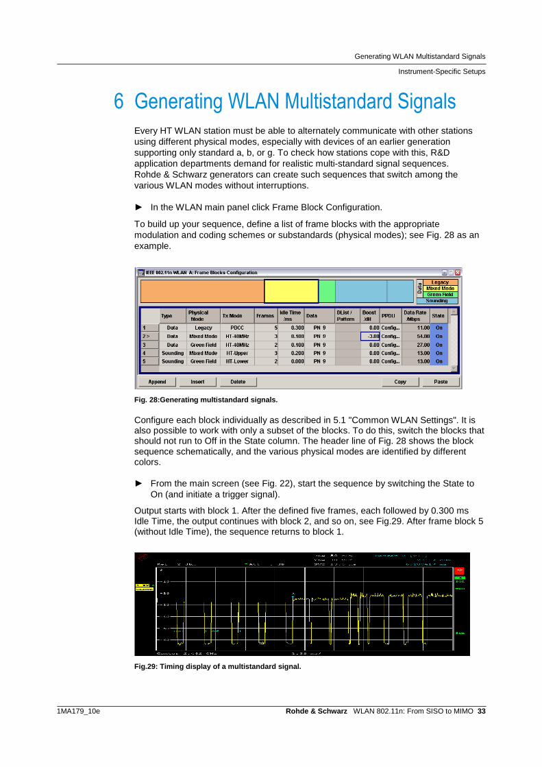
6 Generating WLAN Multistandard Signals Every HT WLAN station must be able to alternately communicate with other stations using different physical modes, especially with devices of an earlier generation supporting only standard a, b, or g. To check how stations cope with this, R&D application departments demand for realistic multi-standard signal sequences. Rohde & Schwarz generators can create such sequences that switch among the various WLAN modes without interruptions. ► In the WLAN main panel click Frame Block Configuration.
To build up your sequence, define a list of frame blocks with the appropriate modulation and coding schemes or substandards (physical modes); see Fig. 28 as an example.
Fig. 28:Generating multistandard signals. Configure each block individually as described in 5.1 "Common WLAN Settings". It is also possible to work with only a subset of the blocks. To do this, switch the blocks that should not run to Off in the State column. The header line of Fig. 28 shows the block sequence schematically, and the various physical modes are identified by different colors. ► From the main screen (see Fig. 22), start the sequence by switching the State to
On (and initiate a trigger signal).
Output starts with block 1. After the defined five frames, each followed by 0.300 ms Idle Time, the output continues with block 2, and so on, see Fig.29. After frame block 5 (without Idle Time), the sequence returns to block 1.
Fig.29: Timing display of a multistandard signal.

Analyzing MIMO Signals
Radio Communication Tester
1MA179_10e Rohde & Schwarz WLAN 802.11n: From SISO to MIMO 34
7 Analyzing MIMO Signals
7.1 Radio Communication Tester
The WLAN option CMW-K652 of the CMW radio communication tester is optimized for production. Unlike in R&D, the focus here is on ensuring that DUTs operate correctly as WLAN devices with as few measurements as possible and in the shortest amount of time. This is generally the case when the most important physical characteristics - such as RX sensitivity, TX transmit power, and frequency and modulation accuracy (EVM) - lie within a specified range. Section 5.2 on page 23 showed how to use a CMW to generate MIMO TX signals for the RX tests of a DUT. This section describes transmitter tests: how one single CMW (with option CMW-K652) measures up to 4 added MIMO TX signals simultaneously from one DUT. Fig.30 shows the test setup and the operation.
Fig.30: Hardware setup for TX tests.
In the test setup, all TX signals of the DUT are added. This could be done in a shielded chamber or by using a 4 to 1 combiner (e.g. Mini-Circuits ZN4PD1-63W+). The CMW gets one composite RF signal.

Analyzing MIMO Signals
Radio Communication Tester
1MA179_10e Rohde & Schwarz WLAN 802.11n: From SISO to MIMO 35
The evaluation inside the CMW is based on space time streams, see Fig.30. Hence for a meaningful result the spatial mapping matrix should be set to direct mapping. This causes a one-to-one mapping of space time streams to TX antennas. Thus a broken TX chain (no power) will be reliably detected and a damaged chain identified by its bad EVM. TX measurements are handled inside the CMW by the WLAN Multi Evaluation task. If this task is not yet visible in the task bar, press the hardkey Measure, and enable a taskbar entry for WLAN Multi Eval. 1. ► Select the task WLAN Multi Evaluation 1. In the window which opens now
► Press the softkey Config...
The Configuration window opens:
Fig.31: WLAN configuration for TX tests. Take Fig.31 as an example. ► Enter Band and Frequency.
► Enter as Expected Nominal Power the DUT's peak burst power.
► 0 dB is recommended as the User Margin.
Then enter the WLAN settings: ► Select 802.11n Comp. MIMO. Set the Burst Type and Band Width; see Fig.31.

Analyzing MIMO Signals
Radio Communication Tester
1MA179_10e Rohde & Schwarz WLAN 802.11n: From SISO to MIMO 36
Fig.32 shows the measurement result for a signal using the MCS 1 modulation and coding scheme. (In the example, only two TX signals are enabled.)
Fig.32: TX measurement result for MSC1.
A single measurement returns the three TX items that are most important in production: the EVM, the Power, and the Center Frequency Error. The statistical displays Current / Average / Max. Results, and Standard Deviation are very helpful in R&D as well as in production. The CMW (with CMW-KM652 option) is a successful balance of very short test times, attractive purchase price, and good test coverage in the production of WLAN MIMO modules.

Analyzing MIMO Signals
Vector Signal Analyzer
1MA179_10e Rohde & Schwarz WLAN 802.11n: From SISO to MIMO 37
7.2 Vector Signal Analyzer
For the various SISO and MIMO measurement tasks, the FSQ and FSV analyzers are the ideal solution with their wide range of measurements options. Below, you find the tests sorted by category, and Fig. 33 on page 38 shows how to access the individual categories directly via the softkeys. Global Results ● Capture Buffer versus Time ● Result Summary: EVM, Frequency Error, Symbol Clock Error ● Result Summary: I/Q Offset, Gain Imbalance, Burst Power, Crest Factor, Pilot
BER, Stream EVM Power vs Time (PVT) ● Full Burst ● Rise / Fall Time Definition EVM ● EVM versus Symbol ● EVM versus Carrier ● Frequency and Phase Error Spectrum ● Spectrum Flatness and Group Delay ● Spectrum Mask ● Spectrum FFT ● Spectrum ACPR Constellation ● Constellation versus Symbol ● Constellation versus Carrier Statistics ● Complementary Cumulative Distribution Function (CCDF) ● Bit Stream ● Signal Field The FSQ and FSV analyzers are a combination of vector signal analyzer and spectrum analyzer. They are used to measure signals in the I/Q domain as well as in the frequency domain. The frequency domain tests are Spectrum Mask and Spectrum ACPR. All other tests evaluate their results from the I/Q baseband. For I/Q as well as for frequency domain, one recording is sufficient to get all of these measurements results at once, ensuring a short testing time.
Analyzing MIMO Signals
Vector Signal Analyzer
1MA179_10e Rohde & Schwarz WLAN 802.11n: From SISO to MIMO 38
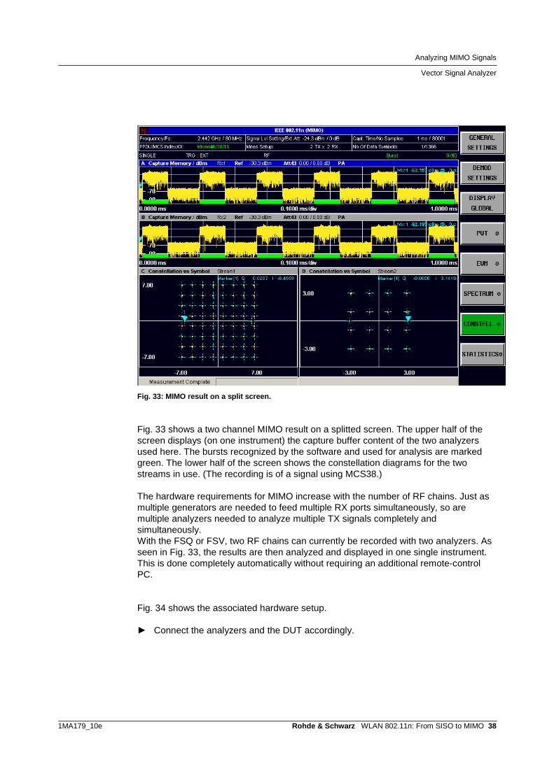
Fig. 33: MIMO result on a split screen.
Fig. 33 shows a two channel MIMO result on a splitted screen. The upper half of the screen displays (on one instrument) the capture buffer content of the two analyzers used here. The bursts recognized by the software and used for analysis are marked green. The lower half of the screen shows the constellation diagrams for the two streams in use. (The recording is of a signal using MCS38.) The hardware requirements for MIMO increase with the number of RF chains. Just as multiple generators are needed to feed multiple RX ports simultaneously, so are multiple analyzers needed to analyze multiple TX signals completely and simultaneously. With the FSQ or FSV, two RF chains can currently be recorded with two analyzers. As seen in Fig. 33, the results are then analyzed and displayed in one single instrument. This is done completely automatically without requiring an additional remote-control PC. Fig. 34 shows the associated hardware setup. ► Connect the analyzers and the DUT accordingly.

Analyzing MIMO Signals
Vector Signal Analyzer
1MA179_10e Rohde & Schwarz WLAN 802.11n: From SISO to MIMO 39
Fig. 34: Hardware setup for 2x2 MIMO. The lower analyzer operates as the master. (Only the master needs the WLAN option FS-K91n, the slave doesn't.) The master configures the slave analyzer and controls the recording process via LAN. ► Use a crossover cable to connect the LAN ports of the two instruments. Both
instruments should be assigned fixed IP addresses (no DHCP). It is not recommended to remote-control the test setup over a wide-meshed network. A possible latency makes the time the master needs to configure the slave indeterminable.
► After you changed the IP addresses, switch the instruments off and then back on again so that the new IP addresses will be recognized by the WLAN option.
Master and slave are synchronized by the 10 MHz reference and a common external trigger signal: ► Set one analyzer to REF ext. and the other to REF int., then connect the 10 MHz
ports accordingly. This is the only setting that is not performed automatically by the master!
Pressing the softkey Run SGL (single) or Run Cont (continuous) initiates arming of the external trigger inputs for the involved analyzers. After that, the setup is ready to get triggered. Once triggered, when the recording has finished, the master reads the memory content of the slave, after which it analyzes and displays the results of both antenna signals.

Analyzing MIMO Signals
Vector Signal Analyzer
1MA179_10e Rohde & Schwarz WLAN 802.11n: From SISO to MIMO 40
Instrument configuration The analyzer has two softkeys used for configuration: GENERAL SETTINGS and DEMOD SETTINGS (see also Fig. 33 on page 38). ► On the analyzer, select the WLAN operating mode (softkeys).
► Click the GENERAL SETTINGS softkey.
This opens the General Settings screen; see Fig. 35.
Fig. 35:General WLAN settings. ► Select the standard IEEE 802.11n (MIMO).
► Enter the operating frequency.
► Set the Trigger Mode to External.
Use the default values for the remaining General Settings. ► Go to the STC/MIMO tab. This opens the screen for the IP addresses; see Fig. 36.
Fig. 36:WLAN STC/MIMO settings.

Analyzing MIMO Signals
Vector Signal Analyzer
1MA179_10e Rohde & Schwarz WLAN 802.11n: From SISO to MIMO 41
► Set the DUT MIMO Configuration to 2 TX Antennas.
► Enter the IP address for the slave analyzer.
(Use the default values of the Advanced Settings.) Spatial demapping Fig. 37 shows a portion of the signal processing in the DUT and the signal restoration in the master analyzer.
Fig. 37: MIMO spatial mapping and demapping.
In the Spatial Mapping block (on the left), which is implemented in every 802.11n module, the antenna signals are derived from the internal space time streams by control of a matrix. The space time streams can use different modulation schemes, such as 64 QAM for stream 1 and 16 QAM for stream 2 (e.g. with modulation and coding scheme 38). The master analyzer reconstructs the original streams in order to determine the individual symbol constellations or to calculate the EVM values. It uses his own recorded data and the data recorded by the slave, provided via LAN. To demap the signal mix, the master must know which spatial mapping was used on the transmit side (if applicable, the space time block coding (STBC) is also automatically decoded in the analyzer).

Analyzing MIMO Signals
Vector Signal Analyzer
1MA179_10e Rohde & Schwarz WLAN 802.11n: From SISO to MIMO 42
To enter the spatial mapping at the analyzer ► Click the DEMOD SETTING softkey.
► Go to the MIMO Settings tab.
Fig. 38: Spatial mapping configuration.
The FSQ analyzer supports the following three mapping modes: ● Direct Mapping ● Spatial Expansion ● Variable Mapping (User Mapping). The matrices for Direct Mapping and Spatial Expansion are defined in the standard. However, you can enter a time shift delay (CSD) for every TX chain. In the User Mapping mode, the matrix elements can be entered as complex values. This permits unrestricted testing and optimization in R&D. ► Set the spatial mapping that was used.
The Demod Settings and Advanced Demod tabs provide a variety of additional setting options that serve primarily as recording filters. Fig. 39 and Fig. 40 are shown here as illustrations only. Refer to the Operating Manual [3] for detailed information. Initially, it is best to work with the default Demod Settings (i.e. Auto all, see Fig. 39).
Fig. 39: WLAN demodulation settings

Analyzing MIMO Signals
Vector Signal Analyzer
1MA179_10e Rohde & Schwarz WLAN 802.11n: From SISO to MIMO 43
Fig. 40 gives you an overview of the Advanced Demod settings. You see the default values which are taken when Auto all is set in the Demod Setting window (Fig. 39). And you see the possible entries.
Fig. 40: WLAN advanced demodulation configuration.
Start recording
Click the RUN SGL (single) or RUN CONT (continuous) softkey. This causes the master to configure the slave. When this has finished, the setup is ready to get triggered.

Analyzing MIMO Signals
Measurement Results
1MA179_10e Rohde & Schwarz WLAN 802.11n: From SISO to MIMO 44
7.3 Measurement Results
From the extensive list of measurements - as described at beginning of section 7.2 - the following measurements are described in detail: Global Results ● Result Summary: EVM, Frequency Error, Symbol Clock Error ● Result Summary: I/Q Offset, Gain Imbalance, Burst Power, Crest Factor, Pilot
BER, Stream EVM Power vs Time (PVT) ● Rise / Fall Time Definition EVM ● EVM versus Carrier Spectrum ● Spectrum Flatness and Group Delay ● Spectrum Mask Constellation ● Constellation versus Symbol ● Constellation versus Carrier Statistics ● Complementary Cumulative Distribution Function (CCDF) All measurements decribed can be done using the FSQ or using the FSV analyzers (master equipped with the K91n options). The following screenshots are taken from the FSQ; screenshots of the FSV may sligthly differ. Result summary The global result summary (Fig. 41) provides an overview of the most important parameters for the transmitter in the DUT. This example shows a measurement of a mixed mode signal with MCS38 and 40 MHz bandwidth.

Analyzing MIMO Signals
Measurement Results
1MA179_10e Rohde & Schwarz WLAN 802.11n: From SISO to MIMO 45
Fig. 41: Global result summary. The error vector magnitude (EVM) distills the overall signal quality for the entire TX chain into a single numeric value. Amongst the DUT power, the Center Frequency accuracy and the Symbol Clock Error a good EVM is the prerequisite to allow devices to interoperate with each other. Except for the power, the Global result summary presents all these basic items on one screen. Fig. 41 provides an overview for all MIMO channels. The min. and max. values show the current variation. Values are green when the limits in the standard are met; otherwise, they are red. The results in Fig. 41 provide an important pass-fail verdict for production testing. In R&D, on the other hand, it's more important to know where a high EVM is coming from. For this purpose, the display as shown in Fig. 42 supplies somewhat more expanded measurement results — which were obtained using exactly the same recording.
Fig. 42: Stream results. Again, this figure shows the measurement results for a mixed mode signal with MCS38 and 40 MHz bandwidth. In this display, the measurement results are organized by stream. This allows to have a closer look inside the DUT.

Analyzing MIMO Signals
Measurement Results
1MA179_10e Rohde & Schwarz WLAN 802.11n: From SISO to MIMO 46
Before discussing this Result Summary, some information about the RX, TX, and Stream labels on the analyzer display should be provided: MIMO highlights the transmission medium. n x m MIMO means that n antennas feed into the transmission channel, and m antennas "read" from it. This paradigm was applied when using the analyzer as a quasi RX station. Fig. 43 shows once again the signal processing in the DUT. When RX is displayed on the analyzer, this means that the signal is being considered which is received at the analyzer input (e.g. the Burst Power and the Crest Factor that is measured here). IQ Offset and Gain Imbalance provide the asymmetries for the TX baseband signals. Other results are converted to values deeper inside the DUT by the analyzer.
Fig. 43: Signal processing in a WLAN module.
The Stream label in the FSQ display identifies those values for which the analyzer has demapped the spatial mapping. This applies, for example, to the constellation diagrams and the EVM results. The pilot EVM is linked to the space time streams, and the data EVM to the spatial streams (if applicable, the analyzer also decodes the space time block coding STBC). Spectrum Flatness and Group Delay (discussed below) can be evaluated for the TX signals as well as for space time streams. Thus the analyzer delivers measurement results you can use to optimize your DUTs. A high EVM in Fig. 42 is caused primarily by I/Q asymmetries or by signal clipping in one or more chains. This is why this display includes the measurement results for I/Q gain imbalance, and the crest factor. On the one hand, it is possible to apply intended signal clipping in the baseband as a power compression in order to avoid having to overdimension the TX output stages as well as to limit the demands on the power supply. The measurement results as shown in Fig. 42 provide a good check as to how close you come to the permissible EVM limits.

Analyzing MIMO Signals
Measurement Results
1MA179_10e Rohde & Schwarz WLAN 802.11n: From SISO to MIMO 47
On the other hand, undesired signal clipping can be caused by overloaded TX output stages. You can see this because the measured crest factor is too small and signal shoulders appear in the adjacent channel power ratio display. (When you use an Rohde & Schwarz generator to generate the transmit signal, you will receive a reliable indication of the normal crest factor for your signal. The crest factor of the generated signal is displayed there.) Additional points of reference are provided by a measurement of the complementary cumulative distribution function (CCDF). Complementary cumulative distribution function (CCDF) With the CCDF, you observe the signal statistics. In the y-axis, the CCDF shows how often the actual signal power exceeds the average power. The x-axis indicates by how many dB the actual power exceeds the average. The maximum x-value is the crest factor.
Fig. 44: CCDF of an MCS38 signal without clipping. Fig. 44 again shows the measurement results for a mixed mode signal with MCS38 and 40 MHz bandwidth, without clipping. You can see a crest factor of approximately 14 dB and a probability of approximately 0.0001 (= 0.01 %). Clipping shifts the measured curve to the left. When you generate your transmit signal using an Rohde & Schwarz generator, you will also receive objective CCDF curves as a reference. Rohde & Schwarz generators supply signals with and without user-defined clipping. You can display these on the generator, or remeasure them with the analyzer. This allows you to determine the extent to which clipping - either desired or undesired - is present. EVM versus carrier / symbol The EVM versus Carrier display on the FSQ allows you to determine whether the data EVM is affected by the subcarrier frequency.
Analyzing MIMO Signals
Measurement Results
1MA179_10e Rohde & Schwarz WLAN 802.11n: From SISO to MIMO 48
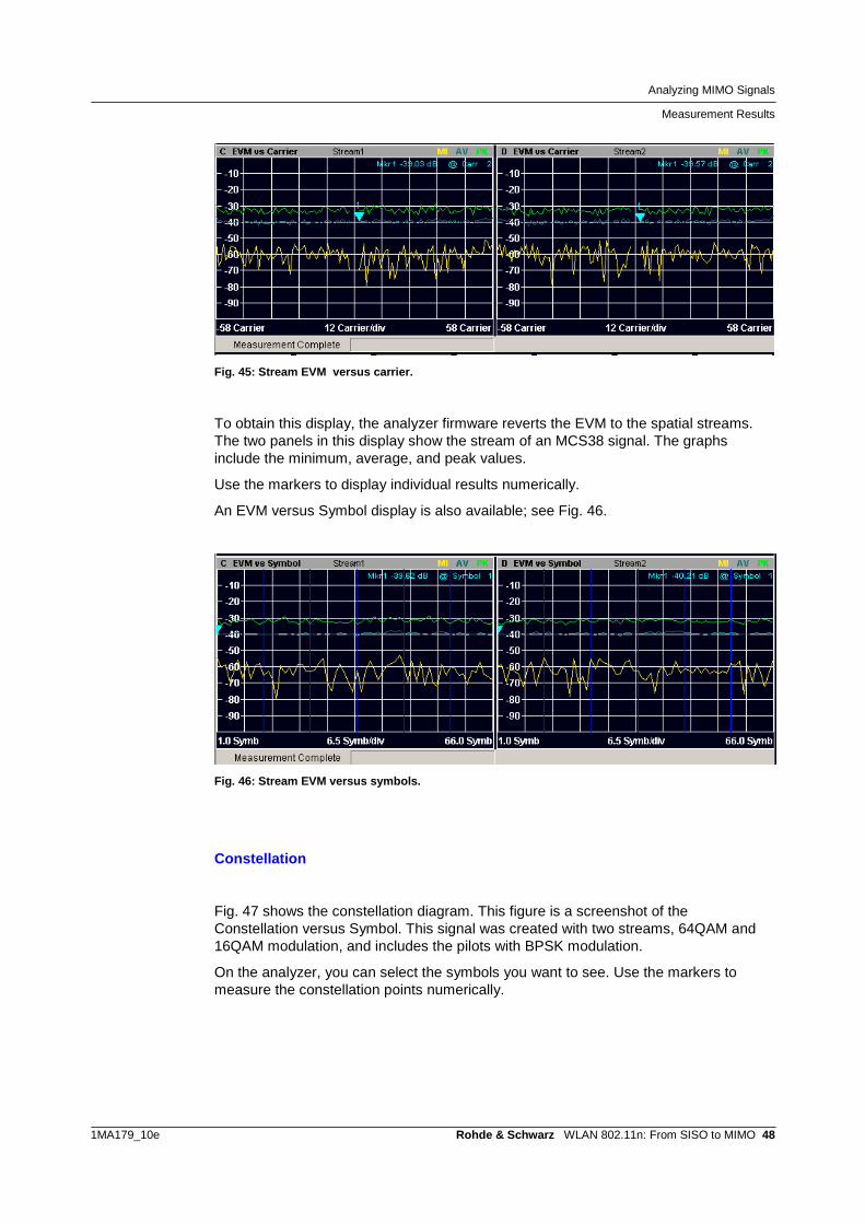
Fig. 45: Stream EVM versus carrier.
To obtain this display, the analyzer firmware reverts the EVM to the spatial streams. The two panels in this display show the stream of an MCS38 signal. The graphs include the minimum, average, and peak values.
Use the markers to display individual results numerically.
An EVM versus Symbol display is also available; see Fig. 46.
Fig. 46: Stream EVM versus symbols.
Constellation
Fig. 47 shows the constellation diagram. This figure is a screenshot of the Constellation versus Symbol. This signal was created with two streams, 64QAM and 16QAM modulation, and includes the pilots with BPSK modulation.
On the analyzer, you can select the symbols you want to see. Use the markers to measure the constellation points numerically.

Analyzing MIMO Signals
Measurement Results
1MA179_10e Rohde & Schwarz WLAN 802.11n: From SISO to MIMO 49
Fig. 47: Stream constellation versus symbol.
A somewhat different representation of the constellation is shown in Fig. 48:
Fig. 48: Stream constellation versus carrier.
This figure shows the Constellation versus Carrier display obtained from the same signal. The I/Q values are displayed in the y-axis, with the I values in yellow and the Q values in blue. Fig. 48 provides a good overview of whether the modulation quality is affected by the subcarrier frequency.
Again, use the makers to select and numerically display individual results.
Rise / fall time definition
It is important to analyze the realtime behaviour of the transmit signals in order to ensure that various stations can communicate without problems. Signal edges that are too flat interfere with bursts in other time slots. If they are too steep, they can cause undesired spurious emissions or affect the DUT power supply which might even increase the EVM.

Analyzing MIMO Signals
Measurement Results
1MA179_10e Rohde & Schwarz WLAN 802.11n: From SISO to MIMO 50
Fig. 49: Power versus time: rise and fall times.
The analyzer therefore includes special marker functions that allow the rise and fall times to be measured exactly. The display of minimum, average, and maximum values is useful when calibrating the DUT. Spectrum flatness, spectrum group delay Again, Fig. 50 shows the block diagram of a 2-channel IEEE 802.11n DUT. If all blocks inside the device were purely digital, each analyzer would receive only its destined TX signal. However, in the analog parts of the DUT, and along the way from DUT to the analyzer (e.g. if you measure over the air), there might be crosstalk between the two channels. This area is shaded in Fig. 50.
Fig. 50: Where crosstalk could occurr.

Analyzing MIMO Signals
Measurement Results
1MA179_10e Rohde & Schwarz WLAN 802.11n: From SISO to MIMO 51
You can check this crosstalk for Spectrum Flatness and Spectrum Group Delay; measurement results are evaluated separately for the direct wanted paths and the unwanted cross paths. On the analyzer you have to ► Select between the physical and the effective channel (MEAS, SPECTRUM,
NEXT, CHN SEL EFF / PHY).
When the physical channel is selected, you will be informed about which portions of the ideal TX1 and TX2 signals you receive at the first, and which portions at the second analyzer, see Fig. 51.
Fig. 51: Paths using the physical channel. Fig. 52 shows the measurement results. You see two direct and two cross portions, as for 2x2 MIMO: the windows C and F display the wanted signals, the windows D and E the signals coming from the other TX, i.e. the crosstalk.
Fig. 52: Measurement results of the physical channel.

Analyzing MIMO Signals
Measurement Results
1MA179_10e Rohde & Schwarz WLAN 802.11n: From SISO to MIMO 52
► To examine a window zoom it to full screen (hardkey DISP, softkey FULL
SCREEN).
The blue dots are the measurement results. Normally, more than one burst will be recorded. So the analyzer provides for each carrier as many dots as bursts are read in. If the signal is stable, the dots coincident for each carrier, and the total spectrum is flat (windows C and F). If the signal varies during the recording, you see more than one dot in vertical direction, and there is no spectrum flatness (windows D and E). The yellow line connects the averaged results. Use the markers to display the measurement values for the individual carriers numerically. Ideally, a DUT will not have any (physical) cross-components. In this case, the results shown in windows D and E represent random noise. The physical crosstalk between two signals is independent of the data content. Thus, using different spatial mapping methods will not influence the measurement results of the physical channel. When the effective channel is selected, you will be informed about which portions of space time stream1 and 2 you receive at the first, and which portions of space time stream1 and 2 you receive at the second analyzer, see Fig. 53.
Fig. 53: Paths using the effective channel.
In this case, you may check the spatial mapping. Ideally, with Direct Spatial Mapping there should be only the direct streams, see Fig. 54 on page 53: The windows C and F show stream1 and 2; the windows D and E provide no valid signals.

Analyzing MIMO Signals
Measurement Results
1MA179_10e Rohde & Schwarz WLAN 802.11n: From SISO to MIMO 53
Fig. 54: Spectrum Flatness of the physical or the effective channel using Direct Mapping. Because for Direct Spatial Mapping the signals before and after the Spatial Mapping are the same, we get the same measurement results as for the physical channel.
However, using Spatial Expansion, both streams are fully visible at the master and at the slave analyzer, see Fig. 55. In this case the crosstalk is covered up by contribution of the cross paths in the spatial mapping matrix.
Fig. 55: Spectrum Flatness of the effective channel using Spatial Expansion. Fig. 56 shows the Group Delay of the effective channel using Spatial Expansion.
Fig. 56: Group delay of the effective channel using Spatial Expansion.

Analyzing MIMO Signals
Measurement Results
1MA179_10e Rohde & Schwarz WLAN 802.11n: From SISO to MIMO 54
Fig. 56 reveils whether the group delay is dependent on the frequency. Too small baseband filters can be detected here. Use the markers to display the measurement values for the individual carriers numerically. Spectrum emission mask
Fig. 57: Spectrum emission mask. This figure shows a signal which is compliant to the IEEE 802.11n spectrum emission mask. For each frequency segment the points with the minimum distance to the mask are marked. The upper half of the screen lists the frequency segments and the numerical results. You can use the pre-programmed specifications from the standard, or you can define your own mask and your own segments. Spectrum emission mask and ACPR represent the RF signal at the master analyzer.

Summary
Measurement Results
1MA179_10e Rohde & Schwarz WLAN 802.11n: From SISO to MIMO 55
8 Summary This application note provides an overview of the current measurement capabilities for WLAN 802.11n MIMO offered by Rohde & Schwarz instruments. It describes how Rohde & Schwarz instruments can be used to easily generate and analyze standard-compliant MIMO signals. The Rohde & Schwarz generators and analyzers deliver all test and measurement capabilities needed in the development of WLAN chips and modules. For cost-effective solutions for development and production use the SMBV vector signal generator and the CMW radio communication tester. The generation and analysis of MIMO signals increases the hardware requirements; in other words, more measurement instruments are needed. However, the instrument firmware is optimized so that measurements are almost as easy to perform as for SISO. Please keep in mind that this application note is just a snapshot of our current offerings. Rohde & Schwarz works continually to expand the functions of its T&M instruments. If your application presents challenges not addressed here, please do not hesitate to contact your closest Rohde & Schwarz office, or e-mail us at [email protected].
9 Literature [1] IEEE Std 802.11n-2009, Amendment 5: Enhancements for higher throughput,
2009 [2] Rohde & Schwarz: WLAN Tests According to Standard 802.11a/b/g,
Application Note 1GP67, 2010 [3] Rohde & Schwarz: IEEE 802.11n, Digital Standard for Rohde & Schwarz
Signal Generators, Operating Manual 1171.5519.12 [4] Rohde & Schwarz: Introduction to MIMO, Application Note 1MA142, 2010 [5] Biglieri, Calderbank, Constantinides, Goldsmith, Paulraj, Poor: MIMO Wireless
Communications, Cambridge University Press, 2007 [6] Rohde & Schwarz: Guidelines for MIMO Test Setups - Part 1, Application Note
1GP50, 2010 [7] Rohde & Schwarz: Guidelines for MIMO Test Setups - Part 2, Application Note
1GP50, 2010 [8] Rohde & Schwarz: Phase Adjustment of Two MIMO Signal Sources with
Option B90 (Phase Coherence), Application Note 1GP67, 2010

Additional Information
Measurement Results
1MA179_10e Rohde & Schwarz WLAN 802.11n: From SISO to MIMO 56
10 Additional Information This Application Note is updated from time to time. Please visit the website http://www.rohde-schwarz.com/appnote/1MA179 in order to download the latest version. Please send your comments and suggestions regarding this application note to [email protected] Please visit also our technology sites at www.rohde-schwarz.com/technologies/mimo .

Ordering Information
Measurement Results
1MA179_10e Rohde & Schwarz WLAN 802.11n: From SISO to MIMO 57
11 Ordering Information Signal generators R&S®AMU200A Baseband Signal Generator 1402.4090.02 R&S®AMU-B10 ARB 64 Msample 1402.5300.02 R&S®AMU-B13 Maseband Main Module 1402.5500.02 R&S®AMU-K54 Dig. Standard IEEE 802.11n 1402.9705.02 R&S®AMU-B14 Fading Simulator 1402.5600.02 R&S®AMU-B15 Fading Simulator Extension 1402.5700.02 R&S®AMU-K74 MIMO Fading 1402.9857.02 R&S®AMU-K254 Dig. Standard IEEE 802.11n (WinIQSIM)1402.9757.02 R&S®SMATE200A Vector Signal Generator 1400.7005.02 R&S®SMATE-B103 RF Path A 100 kHz to 3 GHz 1401.1000.02 R&S®SMATE-B106 RF Path A 100 kHz to 6 GHz 1401.1200.02 R&S®SMATE-B203 RF Path B 100 kHz to 3 GHz 1401.1400.02 R&S®SMATE-B206 RF Path B 100 kHz to 6 GHz 1401.1600.02 R&S®SMU200A Vector Signal Generator 1141.2005.02 R&S®SMU-B103 RF Path A 100 kHz to 3 GHz 1141.8603.02 R&S®SMU-B106 RF Path A 100 kHz to 6 GHz 1141.8803.02 R&S®SMU-B203 RF Path B 100 kHz to 3 GHz 1141.9500.02 R&S®SMU-B10 ARB 64 Msample 1141.7007.02 R&S®SMU-B13 Baseband Main Module 1141.8003.02 R&S®SMU-K54 Dig. Standard IEEE 802.11n 1408.7562.02 R&S®SMU-B14 Fading Simulator 1160.1800.02 R&S®SMU-B15 Fading Simulator Extension 1160.2288.02 R&S®SMU-K74 MIMO Fading 1408.7762.02 R&S®SMU-K254 Dig. Standard IEEE 802.11n (WinIQSIM)1408.7610.02 R&S®SMBV100A Vector Signal Generator 1407.6004.02 R&S®SMBV-B103 RF Path 100 kHz to 3.2 GHz 1407.9603.02 R&S®SMBV-B106 RF Path 100 kHz to 6 GHz 1407.9703.02 R&S®SMBV-B10 ARB 32 Msample (120 MHz, realtime) 1407.8607.02 R&S®SMBV-B51 Baseband Generator, ARB only 1407.9003.02 R&S®SMBV-B55 Memory Extension for ARB, 256 MS 1407.9203.02 R&S®SMBV-B92 Harddisc 1407.9403.02 R&S®SMBV-K54 Dig. Standard IEEE 802.11n 1415.8160.02 R&S®SMBV-K254 Dig. Standard IEEE 802.11n (WinIQSIM)1415.8354.02 R&S®SMW200A Vector Signal Generator 1412.0000.02 R&S®SMW-B106 RF Path A 100 kHz to 6 GHz 1413.0104.02 R&S®SMW-B206 RF Path B 100 kHz to 6 GHz 1413.0904.02 R&S®SMW-B13T Baseband Main Module, two I/Q paths 1413.3003.02 R&S®SMW-B10 ARB 64 Msample (120 MHz, realtime) 1413.1200.02 R&S®SMW-K512 ARB Memory Extension to 1 Gsample 1413.6919.02 R&S®SMW-K54 Dig. Standard IEEE 802.11a,b,g,n 1413.4139.02

Ordering Information
Measurement Results
1MA179_10e Rohde & Schwarz WLAN 802.11n: From SISO to MIMO 58
Spectrum analyzers R&S®FSQxx 20 Hz to 40 GHz 1155.5001.xx R&S®FSQ-K91 WLAN IEEE 802.11 a/b/g/j TX Application Firmware 1157.3129.02 R&S®FSQ-K91N Upgrade of FSQ-K91 to 802.11n 1308.9387.02 R&S®FSVxx 20 Hz to 40 GHz 1307.9002.xx R&S®FSV-K91 WLAN IEEE 802.11 a/b/g/j TX Application Firmware 1310.8903.02 R&S®FSV-K91N Upgrade of FSV-K91 to 802.11n 1310.9468.16 Radio Communication Tester CMW270 Wireless Connectivty Tester 1201.0002K75 CMW-PS272 Basic Assembly 1202.9303.02 (Frequency Range 70 MHz to 3.3 GHz) CMW500 Wideband Radio Communication Tester 1201.0002K50 CMW-PS502 Mainframe 1202.5408.02 (Frequency Range 70 MHz to 3.3 GHz) CMW-KB036 Ext. Freq. Range 3.3 GHz to 6 GHz 1203.0851.02 CMW-S550A Baseband Interconnection Board 1202.4801.02 (fixed link) CMW-B570B RF converter module (TRX) 1202.8659.03 CMW-B590A RF Frontend Module 1202.8707.02 CMW-S590A RF Frontend Module 1202.5108.02 CMW-S600D Front Panel with Display/Keypad 1202.0102.05 CMW-B100A Baseband Measurement Unit 1202.8607.02 CMW-B110A ARB + Realtime Baseband Generator 1202.5508.02 CMW-KM650 TX Measurement WLAN 11a/b/g 1203.1658.02 CMW-KM651 TX Measurement WLAN 11n 1203.9159.02 CMW-KM652 TX MISO Measurement WLAN 11n 1203.9207.02 CMW-KW650 En. WinIQSIM2 Waveforms 11a/b/g 1203.1258.02 CMW-KW651 En. WinIQSIM2 Waveforms 11n 1203.9259.02 CMW-B571B RF up-converter module (TX) 1202.9203.02

About Rohde & Schwarz Rohde & Schwarz is an independent group of companies specializing in electronics. It is a leading supplier of solutions in the fields of test and measurement, broadcasting, radiomonitoring and radiolocation, as well as secure communications. Established more than 75 years ago, Rohde & Schwarz has a global presence and a dedicated service network in over 70 countries. Company headquarters are in Munich, Germany.
Environmental commitment ● Energy-efficient products ● Continuous improvement in
environmental sustainability ● ISO 14001-certified environmental
management system
Regional contact Europe, Africa, Middle East +49 89 4129 12345 [email protected] North America 1-888-TEST-RSA (1-888-837-8772) [email protected] Latin America +1-410-910-7988 [email protected] Asia/Pacific +65 65 13 04 88 [email protected] This application note and the supplied programs may only be used subject to the conditions of use set forth in the download area of the Rohde & Schwarz website. R&S® is a registered trademark of Rohde & Schwarz GmbH & Co. KG; Trade names are trademarks of the owners.
Rohde & Schwarz GmbH & Co. KG Mühldorfstraße 15 | D - 81671 München Phone + 49 89 4129 - 0 | Fax + 49 89 4129 – 13777 www.rohde-schwarz.com


![System-Level Impact of Multi-User Diversity in SISO and ...output (SISO) channels can be created, which greatly enhances link capacity of the MIMO channel [1], [2], [7]–[13]. A tradeoff](https://img.dokumen.tips/doc/110x75/6021949bc098aa318b2b0578/system-level-impact-of-multi-user-diversity-in-siso-and-output-siso-channels.jpg)