Embed Size (px)
Citation preview

After Sales Support TEL: 1300 884 987
1
Wireless Video/Audio Sender
What Your 1 Year Warranty Means Great care has gone into the manufacture of this product and it should therefore provide you with years of good service when used properly. In the event of product failure within its intended use over the course of the first year after the date of purchase, we will remedy the problem as quickly as possible once it has been brought to our attention. In the unlikely event of such an occurrence, or if you require any information about the product please contact us via our after sales support services, details of which can be found in this manual and on the product itself.
After Sales Support TEL: 1300 884 987
2
Contents Safety Instructions .........................................................................................4 Controls .............................................................................................................7
Transmitter ..................................................................................................7 Receiver ........................................................................................................8
About this Appliance....................................................................................9 Assigning the Radio Transmitter and Receiver ........................... 10
Controlling the Audio/Video Source Remotely ..................... 10 Scart or Cinch...................................................................................... 10 Range..................................................................................................... 10 Example Use........................................................................................ 11
Scope of Delivery ........................................................................................ 12 Cables Supplied ................................................................................. 12 Packaging............................................................................................. 12
Connecting the Transmitter.................................................................... 13 Setting Up................................................................................................. 13 Via SCART Connection.......................................................................... 13 No SCART Connection.......................................................................... 13
Example of Transmitter Setup...................................................... 14 Infrared Extender (for Remote Controls) ....................................... 15
Using more than One Device........................................................ 15 Source 1 and Source 2 ..................................................................... 16 Example of Transmitter Setup with Two Devices.................. 17
Connecting the Mains Adapter......................................................... 18 Selecting a Channel............................................................................... 18
Connecting the Transmitter to a Computer ..................................... 19 How to Proceed ...................................................................................... 19
After Sales Support TEL: 1300 884 987
3
Connecting the Receiver.......................................................................... 23 Setting Up................................................................................................. 23 Connecting via a DIN AV Cinch Cable ............................................ 23 Connecting via the SCART Adapter................................................. 23 Connection Using an Aerial................................................................ 23
Example of Receiver Setup ............................................................ 24 Interposing a Device ............................................................................. 25 Connecting the Mains Adapter......................................................... 25 Selecting a Channel............................................................................... 25 Selecting the Source ............................................................................. 25
Setting Channels ......................................................................................... 26 Troubleshooting.......................................................................................... 27
No Audio/Video Transmission...................................................... 27 Poor Reception Quality ................................................................... 27 The Remote Control does not React .......................................... 27
Technical data .............................................................................................. 28 Transmitter .......................................................................................... 28 Receiver ................................................................................................ 28
Declaration of Conformity ....................................................................... 29
After Sales Support TEL: 1300 884 987
4
Safety Instructions Please read these instructions carefully before using the system and note the warnings in the operating instructions. • Always keep the operating instructions close
to hand. If you sell the appliance or give it away, please ensure that you also pass on these instructions.
• Never allow children to use electrical appliances unattended.
Environmental Requirements • Protect the device from moisture and heat. • Avoid placing the devices in poorly ventilated areas (such as
between shelves or where curtains or furniture can block the vents).
• Do not allow foreign bodies or liquids to get into the device. Do not expose the devices to water. Do not place objects that are filled with water, such as vases, on the device.
• Naked flames such as lit candles must not be placed on the devices.
• The rubber feet on the devices may leave marks on furniture surfaces. Place the devices on a suitable underlay if necessary.
Proper Use Your radio transmission system is used for transmitting audio and video signals wirelessly. Never use the system for any other purpose. The system transmits signals from an audio / video source to any other system that processes the audio / video signals.

After Sales Support TEL: 1300 884 987
5
Power Connection • Connect the mains adapters to easily accessible
230V ~ 50Hz power sockets only. • Use only the mains adapters supplied. • Never try to connect the mains adapters to other
connectors as this may damage the devices. • Unplug the device if you will be away for a long
period of time.
Faults • Remove the mains adapter(s) from the power socket
immediately if the mains adapter, the connection cable or the devices are damaged.
• If the appliance is not going to be used for long periods, remove the plug from the mains socket.
• Never try to open and/or repair the devices yourself. • Contact our service centre or qualified personnel.
Health Issues The low transmitting power of the devices eliminates any danger to health according to the current state of research and technology.
Cleaning and Care • Use a soft, dry cloth to clean the devices. • Never use cleaning solutions that could damage the surface
of the devices. Never spray cleaning fluids directly onto the devices.
After Sales Support TEL: 1300 884 987
6
Disposal At the end of its life ensure that the device is disposed of in an environmentally appropriate manner. This may be a local collection point for old devices. Seek the advice of your local management site about the on-site possibilities for disposing of waste.

After Sales Support TEL: 1300 884 987
7
Controls
Transmitter
Front View Left Side
Top Bottom
Rear
1. On/off switch
2. Audio/video transmitter aerial
3. Aerial 433 MHz
4. Channel switch
5. Input for infrared extender
6. AV cinch input (source 2)
7. Switch source 1/2
8. AV-DIN input (source 1)
9. AV-DIN output
10. DC input 7.2 V 320 mA

After Sales Support TEL: 1300 884 987
8
Receiver
Front View Left Side
Top Bottom
Rear
1. On/off switch
2. Audio/video receiver aerial
3. Aerial 433 MHz
4. Channel switch
5. TO TV: 75 Ohm aerial output
6. AV-DIN output
7. Switch source 1/2 (hold down for 10 seconds)
8. DC input 7.2 V 250 mA

After Sales Support TEL: 1300 884 987
9
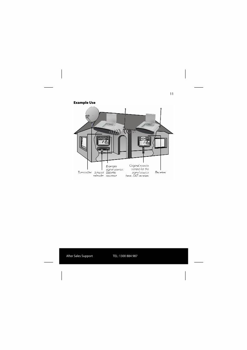
About this Product Your radio transmission system transmits signals wirelessly from an audio/video source to another audio/video device. Typically, the radio signals are sent from a source with an aerial (e.g. a SAT receiver) to another device without an aerial (e.g. a different TV in the building) so that the first device's aerial can
be used for the second device. You can use the source remote control to control this device via the receiver. Your system will work over distances of up to approximately 100m outdoors and approximately 30m indoors. The range also depends on the nature of the wall and ceiling materials. It is also possible to connect the radio transmission system to a PC, for instance to transmit digital presentations onto a TV.
Possible Signal Transmitters and Receivers Typically, the system may be used to transfer the television reception from a satellite receiver, as the source, to another television in your house. Other audio/video sources can be a DVD recorder, a video recorder or a television, a settop box for PayTV or even a PC card. The device connected to the receiver may be, for example, a television or an amplifier.
Audio/video source remote control

After Sales Support TEL: 1300 884 987
10
Assigning the Radio Transmitter and Receiver The transmitter in the radio transmission system is connected to the audio/video source and the receiver is connected to a television or video recorder. The three-core AV cinch cable or the SCART adapter is used to connect the three types of signal – video, audio right and audio left – to the system.
Controlling the Audio/Video Source Remotely You can use the audio/video source remote control to control these devices from the point where the receiver is located. The infrared signals are converted and transmitted as radio signals. The transmitter converts the radio signals back into an infrared signal. The three infrared transmitters in the infrared extender then send these signals on to the relevant devices.
Scart or Cinch If the audio/video source has a SCART connection, use the SCART adapter for the transmitter. If the device connected to the receiver has a SCART connection use the SCART adapter for the receiver. If the device connected to the receiver does not have a SCART connection, use the DIN-AV cinch cable or a 75 Ohm aerial cable. If the audio/video source has a 3.5mm audio output use the audio adapter supplied.
Range Audio and video signals are transmitted in the 2.4GHz range. The range is approx. 100m in the open air and approx. 30m inside. The range may be less depending on environmental conditions.
After Sales Support TEL: 1300 884 987
11
Example Use

After Sales Support TEL: 1300 884 987
12
Scope of Delivery Remove all packing materials. When unpacking, ensure that the following parts are included: • Transmitter • 1x 6V AC adaptor with Australian plug (for transmitter) • Receiver • 1x 6V AC adaptor with Australian plug (for receiver)
Cables Supplied • 1x IR extender cable with three emitters • 1x SCART-to-3.5mm plug adapter • 1x 3 RCA to 3 RCA AV cable • 3 x DIN to RCA cable • 4 x RCA scart adapter
Packaging The radio transmission system is packaged to protect it against transportation damage. Packaging is raw material and can be re-used or added to the recycling system.

After Sales Support TEL: 1300 884 987
13
Connecting the Transmitter
Setting Up
• Place the transmitter on a sturdy surface. • Align the flat side of the transmitter aerial with the receiver. The transmitter is connected to an audio/video source. This can be a SAT receiver, a video recorder, a DVD player, a television or even a graphics card (see below).
Via SCART Connection If the audio/video source has a SCART connection, connect the DIN to RCA cable for the A/V input (supplied) to this device's SCART output using the SCART adapter (supplied), and the A/V input to the transmitter.
No SCART Connection If the audio/video source has no SCART connection, connect the AV cinch cable (supplied) to this device's A/V cinch output, and the AV cinch input to the transmitter. • Connect the three plugs at the other end of the AV cinch
cable to the connectors with corresponding colours on the transmitter.
• The yellow plug is for a video connection, the red one is for audio right, and the white one is for audio left.
• If you want to transmit sound signals only, connect the audio plugs only.
• If you want to connect the transmitter to a 3.5mm audio jack on an audio/video source, use the audio adapter and connect it to the audio plugs on the AV cable.
• To send the video signal on to a TV set positioned where the transmitter has been set up, connect the DIN SCART cable for the A/V output to the SCART input on the TV.

After Sales Support TEL: 1300 884 987
14
Example of Transmitter Setup The following diagram shows a typical arrangement with a satellite receiver and a TV on the transmitter side:
After Sales Support TEL: 1300 884 987
15
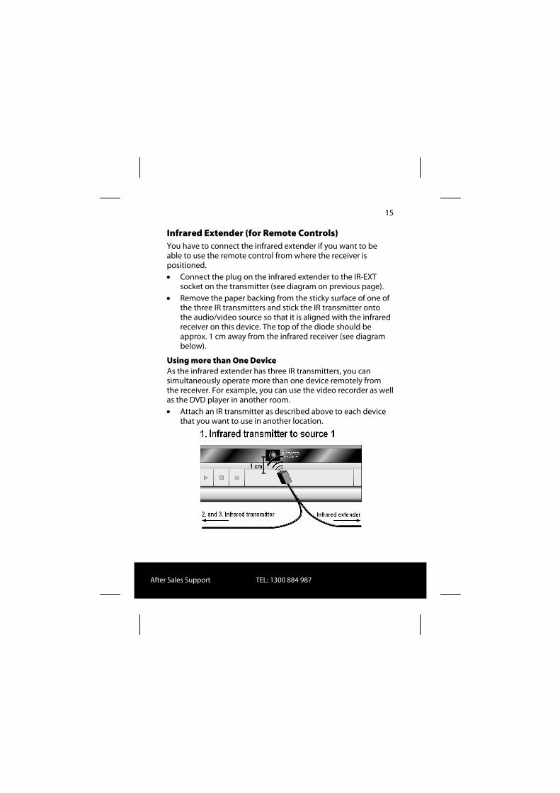
Infrared Extender (for Remote Controls) You have to connect the infrared extender if you want to be able to use the remote control from where the receiver is positioned. • Connect the plug on the infrared extender to the IR-EXT
socket on the transmitter (see diagram on previous page). • Remove the paper backing from the sticky surface of one of
the three IR transmitters and stick the IR transmitter onto the audio/video source so that it is aligned with the infrared receiver on this device. The top of the diode should be approx. 1 cm away from the infrared receiver (see diagram below).
Using more than One Device As the infrared extender has three IR transmitters, you can simultaneously operate more than one device remotely from the receiver. For example, you can use the video recorder as well as the DVD player in another room. • Attach an IR transmitter as described above to each device
that you want to use in another location.

After Sales Support TEL: 1300 884 987
16
Source 1 and Source 2 You can now use the SOURCE 1/2 switch on the transmitter to choose which signal is transmitted to the TV connected to the A/V output. • If you have connected the device to the transmitter's A/V
input, the device is defined as Source 1, whereas it will be Source 2 if connected to the transmitter's AV cinch input.
You can also connect a second device to the transmitter that can send signals from this device to the receiver and control this device remotely from there.

After Sales Support TEL: 1300 884 987
17
Example of Transmitter Setup with Two Devices The following diagram shows a typical arrangement with a satellite receiver, a TV and a DVD player on the transmitter side:

After Sales Support TEL: 1300 884 987
18
Connecting the Mains Adapter
• Connect the mains adapter to the 6V socket (DC 7.2 V) on the transmitter.
• Remove the protective cover and insert the mains adapter into the socket (230V ~ 50Hz).
• Set the ON/OFF switch to the ON position. The red operating LED will light up.
• Open up the transmitter aerial and align it with the receiver.
Selecting a Channel
• Use the channel switch at the bottom of the device to select a channel (A/B/C/D) to which the signal is to be sent.

After Sales Support TEL: 1300 884 987
19
Connecting the Transmitter to a Computer You can also connect the transmitter to a computer in order to transmit computer output to a television, for example. It does not usually make sense to transmit computer output to a TV for running computer applications, since the TV’s screen display is not usually good enough to display the higher resolution computer image.
If you want to show videos or presentations, however, displaying them via the TV is highly recommended.
The following requirements have to be fulfilled: • Your computer has a video output that provides video
images suitable for a TV. • The operating system and the drivers for your graphics card
support video output.
How to Proceed Output via video output is activated differently depending on your operating system and graphics card. As there are numerous combinations of these, we can only provide general instructions here. Please check the operating instructions for your computer or graphics card to see how you can divert the image to video output. The following example requires a PC running the Windows® 98 operating system or above. • Close all programs and switch off your computer. • Refer to the operating instructions for your PC and follow
the instructions for using video output. • Connect the yellow plug on the AV cinch cable to the
graphics card’s video output. If your graphics card does not have a cinch output, use a suitable adapter (optional accessory).

After Sales Support TEL: 1300 884 987
20
• Connect the red and white plugs on the AV cinch cable to your PC’s audio output. PCs usually have 3.5mm stereo jacks, so you can use the adapter supplied.
• Now connect the free end of the AV cinch cable to the corresponding coloured connectors on the transmitting station.
• Now switch on the transmitting station, the receiving station and your TV, and choose the appropriate video channel on your TV.
• Start your PC and wait until the operating system has fully loaded.
• Click once on the Desktop with your right mouse button and choose ”Properties” to display the ”Display Properties”:

After Sales Support TEL: 1300 884 987
21
• Now click on ”Settings” to configure your PC’s output. Various graphics cards can differ enormously here.
You should therefore check the relevant operating instructions to see how you should proceed. You can usually use the F1 key to call up online help, which provides you with detailed information. If all the settings are correct, the image from the PC will now be displayed on the TV.

After Sales Support TEL: 1300 884 987
22
Trademarks MS DOS® and Windows® are registered trademarks of Microsoft®.
Pentium® is a registered trademark of Intel®.
Limitation of Liability for Loss of Data/Consequential Losses Backup:
To avoid loss of data you should back up all data to external media (such as CD-R) each time you change your PC system. MEDION AG accepts no liability for loss of data.
Functionality:
The enormous differences between operating systems and graphics cards mean that we cannot guarantee the functionality described in this section ("Connecting the transmitter to a computer"). Please contact a specialist supplier or expert.
Consequential losses:
When you connect the radio transmission system to your computer, you must take note of the operating instructions for your computer, the software used and additional components.
We are not liable for damages or loss of data that were caused by incorrect or improper use.
After Sales Support TEL: 1300 884 987
23
Connecting the Receiver
Setting Up
• Place the receiver on a sturdy surface. • Position the receiver so that the front with the LED
operating indicator is facing you. • If you are using the remote control from the audio/video
source, point it towards the receiver. • Open up the transmitter aerial and align it with the
transmitter until you have the optimal image. There are several ways to receive the transmitter’s audio/video signals on a different device.
Connecting via a DIN AV Cinch Cable
• Connect the DIN AV cinch cable to the receiver's A/V output and the corresponding sockets on the receiving device (e.g. the TV).
Connecting via the SCART Adapter
• Connect the DIN AV cinch cable to the receiver's A/V output and the SCART adapter for the receiver.
• Plug the SCART adapter labelled "Receiver" into the SCART input on the receiving device (e.g. the TV).
Connection Using an Aerial If the receiving device does not have a SCART connection nor connectors for the AV cinch cable, you can also use a 75 Ohm aerial cable. Please note that sound or vision quality may be slightly poorer. • Connect an aerial cable with the TO TV connector to the
receiver and the corresponding connector on the device.

After Sales Support TEL: 1300 884 987
24
• On your TV, choose channel 36 for displaying the signal or tune the stations in on your TV.
Example of Receiver Setup The diagram below shows a typical setup for the receiver and a TV, either with the DIN AV cinch cable and SCART adapter or with a 75 Ohm aerial cable on the receiver side.

After Sales Support TEL: 1300 884 987
25
Interposing a Device Instead of connecting the receiver directly to the television, you can also interpose a different audio/video device. This could be a video recorder, for example, which you can then connect with the receiver as already described.
Connecting the Mains Adapter
• Connect the mains adapter to the 7.2 Volt connector on the receiver.
• Plug the mains adapter into an easily accessible socket (230V ~ 50Hz).
• Turn on the receiving device, such as the television, and set the receiver’s ON/OFF switch to the ON position. The red operating LED will light up.
Selecting a Channel Check that the receiver is set to the same channel (A/B/C/D) as the transmitter.
Selecting the Source If you have connected two devices to the transmitter, you can now use the SOURCE 1/2 switch to switch between the receiver of the first (Source 1) and the second (Source 2) device. • To do this, keep the SOURCE 1/2 button at the rear of the
receiver pressed down for around 10 seconds, until the device switches over.
• You can also press down any button on the remote control belonging to a device that is connected to the transmitter for 10 seconds, and it will switch devices.

After Sales Support TEL: 1300 884 987
26
Setting Channels Your radio transmission system has four channels – i.e., four different frequencies can be used. The channel switch is on the bottom of both devices. • Set the transmitter and receiver to the same channels. • Test which channel (A/B/C or D) provides the best reception. • You can also use the four channels to operate up to four
radio transmission systems. Note that the radio signals that are created during operation may affect other radio systems such as a WLAN system. In this case, switch to a different channel for transmitting the signal.

After Sales Support TEL: 1300 884 987
27
Troubleshooting If errors occur, check first that the system was set up correctly. The following overview may help you:
No Audio/Video Transmission • Are all mains adapters plugged in? • Are the transmitter and the receiver switched on? • Are the channels for the transmitter and the receiver the
same? • Is the transmission source switched on? • Walls and ceilings can reduce the signal range. • Check the connections to the connected devices.
Poor Reception Quality • Realign the transmitter and receiver aerials. • Change the position of the transmitter and the receiver
slightly. • Interference can be caused by several factors, such as radio
waves from other devices. • Other radio systems such as a WLAN system may similarly
affect radio transmissions. If possible, switch to a different channel on the other radio system.
• Choose a different channel.
The Remote Control does not React • Point the remote control directly towards the receiver. • The infrared transmitter’s diodes should be approx. 1 cm
away from the infrared receiver of the audio/video source. • Have you aligned your infrared diodes correctly?

After Sales Support TEL: 1300 884 987
28
Technical data
Transmitter: Mains adapter Input: 230V ~ 50Hz Output: 7.2 V 320 mA 4 channels Frequency range: 5725 - 5875 GHz Connections: 2 audio cinch 1 video cinch 1 DIN output 1 DIN input Feedback channel for remote control signal: 433MHz
Receiver: Mains adapter Input: 230V ~ 50Hz Output: 7.2 V 250 mA 4 channels Frequency range: 5725 - 5875 GHz Connections: 1 DIN output 1 aerial output 75 Ohm Subject to technical changes.

After Sales Support TEL: 1300 884 987
29
Declaration of conformity The devices comply with the European guidelines for radio equipment and telecommunications equipment. (R&TTE 1999/5/EG). The following harmonized standards were used: 1. Safety: - EN 60950 2. Electromagnetic compatibility: - EN 301489 - EN 300683 3. Efficient use of the radio frequency spectrum: - EN 300220-1-3 - I-ETS 300440