Embed Size (px)
Citation preview
1
Wireless Passive RFID Crack Width Sensor forStructural Health Monitoring
S. Caizzone, E. DiGiampaolo
Abstract—All mechanical structures are subject to deformationand cracks, due to fatigue, stress and/or environmental factors. Itis therefore of uttermost importance to monitor the mechanicalcondition of critical structures, in order to prevent catastrophicfailures, but also to minimize maintenance costs, i.e. avoidunnecessary inspections. A number of technologies and systemscan be used for this purpose: among them, the ones proposingthe use of wireless passive crackmeters have a strong impactpotential, in terms of simplicity of installation and measurementand low cost. The present work hence shows a crack widthwireless radio frequency identification (RFID) sensor, developedfor applications on various materials (such as concrete and metal)and able to detect sub-millimeter deformations occurring on theobject on which it is placed. A design method based on highsensitivity phase detection is shown.
Index Terms—RFID, array, mutual coupling, sensors, wirelesscommunications, SHM, crack monitoring
I. INTRODUCTION
Structural health monitoring (SHM) systems [1] are auto-mated tools, aimed at rapidly identifying the onset of structuraldamage and at tracking the condition of structures duringforced or natural excitation. They resort to novel sensing tech-nologies by combining extensive monitoring infrastructureswith specific algorithms. With the increase in the demand forsuch systems and because of the large set of applications, thefield of SHM has embraced a number of different technologiesthat differ in terms of complexity, measurement accuracy,life span and cost. A comprehensive review of the topicincluding physical monitoring principles, sensors, systems,signal processing and applications is shown in [2]. Regardingthe used techniques, it is possible to distinguish among in-situ, on-demand and remote monitoring techniques. The firstfamily is based on the deployment of several local sensorspermanently coupled with structural elements: accelerometers,fiber optics, ultrasonic devices are some examples. The secondfamily of techniques is based on instrumentation brought tothe measurement site on-demand: X-ray, infrared thermogra-phy, laser scanning, microwave radar are the most commonones. Finally, the third family resorts to sensors far from theinfrastructure site, such as those based on photogrammetry andinterferometry techniques. To limit the discussion to the area ofin-situ SHM systems, the available techniques can be divided
S. Caizzone is with the Institute of Communications and Navigation, Ger-man Aerospace Center (DLR), Oberpfaffenhofen, Germany, as well as with theDISP, University of Roma Tor Vergata, Italy. E-mail: [email protected].
E. DiGiampaolo is with the Dipartimento di Ingegneria Industrialee dell’Informazione e Economia, University of L’Aquila, Italy. E-mail:[email protected].
into two groups, according to the use of wired or wirelesstechnology.
Among the wired ones, high measuring precision and greatresolution can be obtained, for instance, using fiber opticsystems (e.g.[3][4]). However, such systems involve a timeconsuming installation, due, among others, to wiring problems;moreover, they are quite expensive, because of the complicatedmanufacturing as well as the extensive signal processing.
On the other hand, thanks to the fast and easy installation,wireless sensors are gaining a growing interest. A summaryreview is reported in [5]. In active wireless systems, eachsensor node is typically battery-powered and permits a longdistance transmission of the measured data. Although com-mercial solutions are appearing on the market, their cost andcomplexity is still relatively high and their autonomy limitedby the lifespan of the battery (e.g. [6]).
Passive wireless systems, instead, harvest their energy fromthe environment or collect it from the powered read-outunit during the wireless communication: they have a simplerelectronics and enable hence lower costs, at the expense ofsome sensor performance. Despite this reduction in obtainableperformance, they appear as most appealing for the perva-siveness that their low cost could enable. In practice, a largedeployment of such sensors can be used [7] as an indicativemonitoring ecosystem, where passive sensors would provideinitial information and detect criticalities with a low costinfrastructure spread out over the area to monitor: only thelocations exhibiting problematic evolution of the monitoredparameters would then be assessed with more precise (andexpensive) technologies. This concept is for instance wellsuited for monitoring the evolution of already existing cracks(such as in historical buildings) or of junctions prone to cracks,similarly to what is often done with cheap visual crackmeters.In this case, a low-cost wireless passive sensor, able to detectsub-mm crack width variations with a dynamic range of afew mms, could become an enabler for a whole new set ofindicative monitoring use cases.
A review of passive wireless sensors for SHM is reported in[8]. We will take into consideration only chip-less and RFIDsensors here for brevity: they exploit the shift of resonancefrequency of an antenna due to a modification of the antennageometry or the underlying substrate because of a mechanicalstress. Rectangular [9] and circular [10] microstrip patchantennas have been used in chip-less systems: they exploitthe change of the resonant frequency due to the change ofthe characteristic dimensions of the antenna, provoked by thestrain applied on the antenna, and record it wirelessly bymeans of a second antenna connected to a vector network

analyzer (VNA). The read distance is in general short (i.e. tensof centimeters) while the measurement accuracy can be good.A small microresonator structure that generates an amplitudepeak in the radar cross-section at resonance is instead proposedin [11]. The frequency-domain backscatter signature of theresonator includes its ID and the measured value. The trans-duction of the strain information into the signal is obtainedby a variation of the capacitive element of the resonatoralong with the measured quantity. Sub millimeter measurementaccuracy is achieved, but a large frequency band is used and aspectrum analyzer is required. The operating distance is below1m. Another interesting solution is proposed in [12], where atwo-element antenna array is placed on the two sides of thecrack and the evolution of the latter is monitored by exploitingthe changes in array radiation characteristics when the distancebetween the elements changes. However, the system is notstandardized and requires a precise measurement readout, withexpensive equipment.
The previous examples have the drawback of high costsand/or complicated measurement read-out. On the other hand,RFID sensors could help in overwhelming such issues, thanksto their ease of installation and wireless readout. Moreover, theuse of a fully standardized identification technology (ultrahighfrequency (UHF) RFID EPC1Gen 2) has the benefit of lowcost of commercial off the shelf (COTS) components. A fewpassive RFID designs have been proposed in recent literatureto serve as deformation/crack sensors. They all exploit detun-ing of the tag due to deformation of the structure. A metal plateis used in [14] to detune an RFID tag applied on a beam as itgets deformed. Deformation is measured by monitoring the tagbackscatter signal strength and the minimum turn on power.A rectangular microstrip patch antennas in combination withIC chips is proposed in [15], forming an RFID strain sensorwhose resonant frequency changes along with change in itsdimension due to strain. A meander dipole antenna is used in[16] as a strain sensor exploiting the change of the turn-onpower in consequence of the detuning due to the stretching ofthe meander. Detuning based sensors however sacrifice readrange for the sake of sensing: the read range reduction, due totag detuning, can also be of the order of 10 dB. In [17], instead,the authors have demonstrated that phase information fromRFID tags can be usefully exploited to infer deformation of ad-hoc designed couplet of RFID tags, only weakly affecting theread range. The coupling between two (dipole) antennas is inthat case exploited, somehow similarly to the concept proposedin [12], but allowing here for compensation of the varying self-impedance through the mutual impedance. A comparison ofthe different system approaches, with a summary of achievableperformance and required setup, is shown in Tab. I.
The present work, taking cue from [17], explores how toadapt and optimize the design of RFID passive sensors forcrack monitoring in environments considered to be RFID-harsh, either because of relatively high dielectric losses (likein concrete) or because of the presence of metallic materials.
Passive RFID sensors do in fact depend on the surroundingenvironment, because they rely on wireless measurement ofantenna-related parameters.
Dipoles, for instance, as the ones used in [17], are not
suitable for this kind of applications because of their reknowndependence on the underneath material. On the other hand,microstrip patch antennas, thanks to their ground plane, aresubstantially less influenced by the underlying materials thandipole-type antennas: in fact, the ground plane helps in insu-lating the antenna from what is underneath, effectively makingthe antenna almost insensitive to the underlying material. Forthe former reasons, a microstrip antenna has been consid-ered in this work: the miniaturized planar-inverted-F antenna(PIFA) proposed in [18] (with a realized gain around -8 dBi)served as starting point for the present investigation.
Systemtypology
Relevantparameters Performance Measurement
set-upResolution Read Range
Chip-less
resonantfrequency[9],[10],[11]
sub-mm <1 m complex(VNA-based)
null-patternposition [12] few mm >>1m complex
RFIDdetuning-based
backscatteredpower [14] few mm
~1 mspecificequipmentturn-on power
[15] sub-mm
turn-on power[16] sub-mm simple
(COTS-based)
RFIDphase-based
phase ofbackscatteredsignal ([17] andpresent work)
sub-mm >1 m simple(COTS-based)
Table ICOMPARISON OF DIFFERENT TECHNOLOGIES FOR CRACK WIDTH
ENLARGEMENT DETECTION IN SHM APPLICATIONS
A proper design for the adequate antenna typology incouplet configuration will be shown in this work, enabling thesensor to gain in terms of applicability on various materialsand releasing it from the need for in situ structure-dependentcalibration. The size of the tag antenna (including also theground plane) is moreover an issue, with miniaturized solu-tions being preferred because of minor obstruction concerns inreal-life structures as well as of the inherently local nature ofcrack measurement. However, miniaturized antennas are morestrongly influenced by the surrounding environment, as theirfields are not totally confined, but extend to nearby objects.
A proper trade-off between miniaturization and materialindependence is found in Sec. II.C.
The paper is divided as follows: the theoretical backgroundand the design approach will be shown in Sec. II, whilemeasurements of the prototype are presented in Sec. III.Finally, conclusions are drawn in Sec. IV.
II. THEORY AND DESIGN METHOD
A. Theoretical Background
The envisaged system is shown in Fig. 1: it is composedof an RFID reader, wirelessly interrogating a couplet of RFIDtags, each placed on one edge of a crack on the surface of thestructure to monitor.
If two close RFID tags, strongly coupled with each other,are considered, it is possible to achieve a good variation ofthe phase of the backscattered field with respect to variation

of their mutual distance [17], hence having the chance to turnthe RFID couplet into a deformation sensor.
Figure 1. Envisaged system layout: an RFID reader wirelessly interrogatesa couplet of RFID tags placed on a cracked wall-like structure and retrievesdeformation data
However, particular care has to be taken in order to limitthe variation of the useful read range of the tags during thesensing process: as a matter of fact, coupling as well asdetuning can worsen the power requirements of tags (i.e. tagscould be readable only from a shorter distance). To avoid theshortening of the communication distance, a trade-off analysisbetween the communication (i.e. read range) and sensing (i.e.deformation) requirements shall be implemented. The final aimof the design is to develop a sensor with good phase (andhence crack width) sensitivity and, at the same time, no drasticvariation in communication capabilities (i.e. read range) alongthe sensing process.
For what concerns sensing, the phase of the tag n (n = 1, 2)of a couplet of symmetric tags can be expressed [17] as
ϕn[d] = ϕZ + ϕ0 = (1)
= arg
− ZS [d]− ZM [d] + ZC
(ZS [d] + ZC) (ZS [d] + ZM [d] + ZC)
+ ϕ0
where ZS is the self impedance of one tag, ZM is the mutualimpedance, ZC the chip scavenging impedance and d is themutual distance between the tags.ϕ0 is defined as ϕ0 = argf(rn) = ϕr + ϕh, where
f(rn) ∝ λ2
π2
√PinRradR /2GRR
radn GOCn (hn · hR)2
e−j2krn
4r2n(2)
and where λ is the wavelength, Pin is the power suppliedby the reader, RradR and Rradn [d] are, respectively, the radiationresistance of the reader and of the n-th tag antenna, GR is thegain of the reader antenna, GOCn [d] the gain of the n-th tag(when the other tag is in open circuit condition), hR and hn[d]are respectively the effective height unitary vector of the readerand of the n-th tag antenna.
The phase of the tag is thus composed of three parts:
ϕn = ϕZ + ϕ0 = ϕZ + ϕr + ϕh (3)
The first one (ϕZ) depends only from the impedance matrixand the chip impedance (being the first term of Eq. 1); the
second one (ϕr = −2krn) is determined by the reader-tagsdistance and the third one from the phase of the product ofeffective heights of reader and tag (ϕh = arg(hn · hR)2).It will here be assumed that the measurement setup is fixed,meaning that the distance and orientation between reader andtags do not change for subsequent measurements. Consideringthat the distance d between the tags has a range of few mm,corresponding to hundredths of λ, we can assume that theeffective height of the tag will not change strongly in the rangeof d. Therefore, ϕr and ϕh can be assumed constant with thecrack evolution and therefore the phase change will only bedue to ϕZ .
Communication properties on the other hand depend mainlyon the power transmission coefficient τn and realized gainGn, which influence the power scavenging capability, andthe modulation efficiency MEn, that affects the capabilityof correct demodulation of the signal backscattered from thenth tag to the reader [20]. Both parameters can be optimizedas functions of the self and mutual impedances, obtainingdifferent trade-offs in terms of τn and MEn.
The power scavenging capability, maximized around theHermite condition Zin,n = Z∗
chip, is usually expressed interms of power transmission coefficient [17]:
τn[d] =4RCR
radS [d]
|Zin,n[d] + ZC |2(4)
whereRradS and RC are respectively the self radiation resis-tance and chip resistance, while Zin,n is the input impedance,and realized gain
Gn[d] = GOCn [d]τn[d]χn (5)
with χn =∣∣∣hn · hR∣∣∣2being the polarization mismatch
coefficient.The modulation efficiency ME shall instead be maximized
for optimizing the modulated backscattered power and can bewritten as [20]
MEn[d] =4R2
in,n[d]∣∣[ZOFFC − ZONC
∣∣2∣∣Zin,n + ZONC∣∣2 ∣∣Zin,n + ZOFFC
∣∣2 (6)
thus with a clear dependence on both the modulationimpedances of the RFID chip, ZONC and ZC
OFF , and onZin,n. The modulation efficiency is particularly important inthe case of up-link limited systems. In the case of down-linklimited systems, e.g. for typical passive systems as well asfor the solution presented in this work, it is instead essentialto optimize the scavenged power required for turning on thechip. It is worth recalling that also passive systems can beup-link limited, for instance when the latest top performingRFID chips, with their constant improvement in terms ofsensitivity, are used, together with simple (and not extremelysensitive) readers: in such case, the modulation efficiency shallbe considered as the parameter to optimize, implying the needfor measuring the actual values of both impedance states ofthe chip [21]. In our case, however, by performing a powerbudget calculation [22] with the used NXP G2XM chip, thesystem has been proven down-link limited and therefore the

realized gain, incorporating all the necessary phenomena (i.e.impedance matching through τn, polarization mismatch χn,antenna gain GOCn ), will be in the following the parameter tooptimize for the communication capability.
Figure 2. Isolines of: a) realized gain; b) phase over mutual distance andfrequency for a couplet of PIFA antennas
Fig. 2 shows Gn and ϕn of one tag of a couplet of PIFAantennas (see Fig. 3) versus frequency and mutual distance,giving a rationale for the use of (the phase of) coupled tagsfor deformation monitoring.
It can in fact be seen that in a particular area of the graph(marked by the black vertical line and corresponding to aspecific working frequency), Gn has few variations, implyingminimal degradation of communication performance (i.e. Gnis almost constant), while phase is strongly varying withmutual distance, especially in the first millimeters. Operationin a zone with such properties could therefore be particularlysuitable to satisfy both requirements on communication andsensing, which, on the other hand, would not be satisfied atthe same time in other regions of the plot.
Figure 3. Proposed crack width sensor, composed of two RFID tags placedeach on one edge of a cracked structure (top view). Each tag consists of aPIFA antenna. Relevant design parameters are shown
B. Design Procedure
The performance of the sensor (in terms of phase andrealized gain variations) can be optimized by means of anappropriate choice of the design parameters of the antennacouplet, which then become degrees of freedom (DOFs) forthe optimization process. The design parameters that mainly
affect the tuning of the chosen antenna (Fig. 3) are a (thewidth of the H-slot) and n (the slit length).
It is therefore possible to optimize the performance of theRFID couplet, choosing n and a as DOFs and 4ϕmin andGnmin as requirements.
The optimization constraints can be formally expressed asϕn(dmax)− ϕn(dmin) ≥ ∆ϕn,min
Gn(d) ≥ Gn,min(7)
∀n, ∀dε[dmin; dmax]
In other words, only configurations (i.e. given values of aand n) of the antennas satisfying simultaneously requirementson minimal variation of phase and minimal realized gain alongthe whole process (i.e. for the whole interval of distances) canbe accepted for the final design.
In the optimization process, we choose the followingrequirements for communication and sensing Gn,min =−16 dBi and ∆ϕn,min = 80 ° with a range of distances[dmin; dmax] = [1; 3] mm. The choice of the minimumvalue of realized gain is related to the specific kind ofantenna adopted: in this case, the miniaturization of the singleantenna (as shown in [18]) as well as the additional lossesdue to coupling do not allow for high gain values. However,Gn,min = −16 dBi still seems a reasonable value, as it guar-antees a read range of around 1.5 m for an equivalent isotropicradiated power (EIRP) of 3.2 W and with the used microchip(i.e. a NXP G2XM with a sensitivity pc,n of -15 dBm), whichis large enough for the proposed application. Even better readranges can be obtained if using more performing chips, i.e.chips with lower sensitivities. The choice of the minimumvalue of the phase difference ∆ϕn,min originates from thedesired sensitivity of the couplet, i.e. the desired variation ofthe phase over a given interval of distance. ∆ϕn,min shall behigh enough to easily distinguish the phase variation due tothe crack enlargement, with respect to the phase resolutionof the reader. Higher values will thus enable finer crack widthresolutions. On the other hand, if the requested ∆ϕn,min is toohigh, the optimization process might not converge. A balancedvalue has hence been chosen, enabling to clearly distinguishsub-mm displacements.
Figure 4. Proposed deformation sensor (side view). The sliding plexiglassstructure is mutuated from visual crackmeters
In order to ensure maximal applicability of the sensor onareas made of different materials (for instance, the concreteblocks of buildings as well as metallic plates of an avionic
part), the two RFID tags have been equipped with a Plexiglassliding support (Fig. 4), that ensures a similar and controlledrelative positioning and sliding of the tags on every structurethey might be placed on. In the present work, only a slidingof the tags along the direction that connects one tag to theother will be considered, i.e. only an enlargement of the crackwidth will be taken into account.
Due to the fact that the used antennas are miniaturized, theyare not totally able to confine the fringing field produced at theedges of the PIFA antennas. The use of an additional and largerlayer of copper below the tags may help therefore in reducingthe field interacting with underlying materials, improving thetags’ invariance from the structure below. For such reason,the upper surface of the lower horizontal Plexiglas sheet isfully covered with a thin copper foil (referred to as "extendedground"). The width of the copper sheet (and of the Plexiglas)has at first been assumed as relatively big (Wextgnd= 200 mm),in order to ensure isolation from the underlying material: thisdimension can of course be diminished if the specific appli-cation requires a smaller lateral footprint, however with thedisadvantage of a decreased independence from the underlyingmaterial, as shown in Sec. II.C.
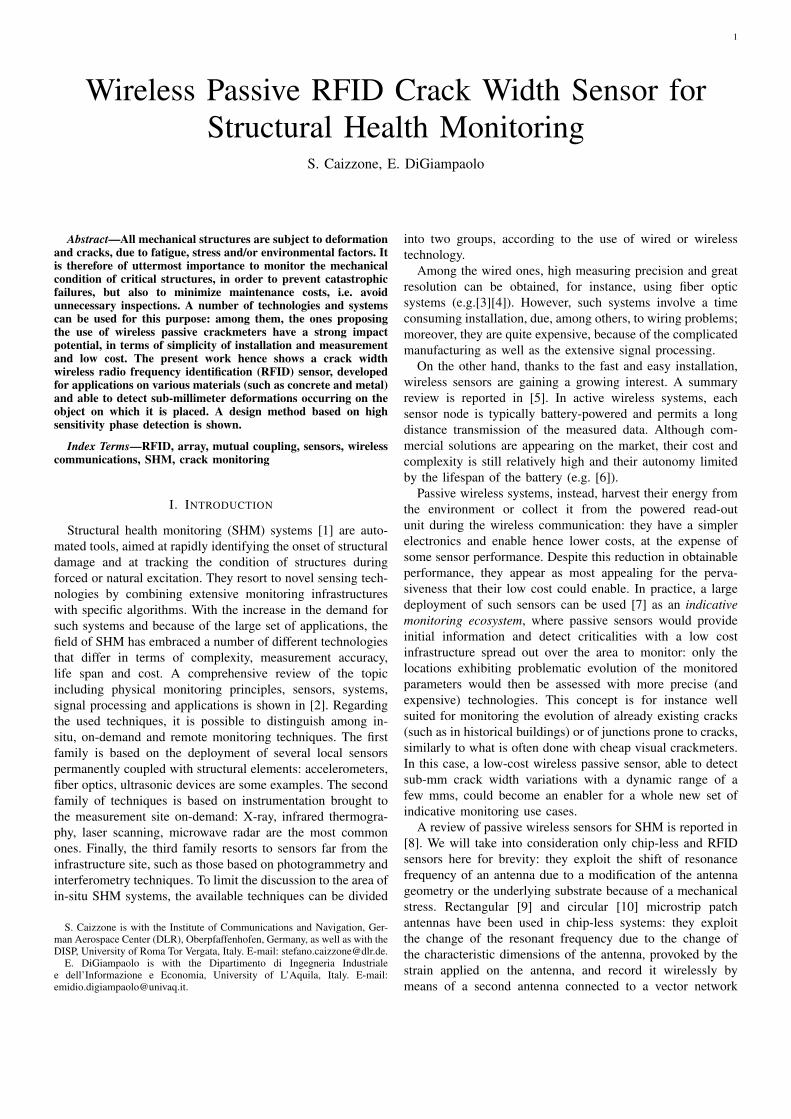
Figure 5. 4ϕ vs. Gn chart for two strongly-coupled PIFA antennas placedover two concrete plates (as in Fig. 12) with n and a as degrees of freedom.Blue and red areas highlight regions of the parameters domain where optimalperformance, in terms of communication and sensing, are obtained.
Considering the requirements expressed above and havingassumed that the sensor, comprising the couplet of tags andthe Plexiglas support, is fixed on two adjacent concrete plates(with dimensions 50x25x10 cm) and that a NXP G2XM chipis used (with Zc = 15− j135 Ω at fRFID = 867MHz), theresulting 4ϕ and Gn chart is plotted in Fig. 5.
Considering the intersection of admissible regions for com-munication and sensing, shown respectively as blue and redareas in Fig. 5, optimal results are found for n = 15.0 mmand a = 4.2mm .
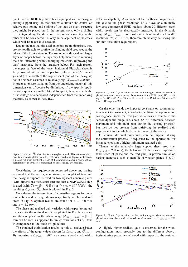
The phase and realized gain variation with respect to mutualdistance for the optimal result are plotted in Fig. 6: a strongvariation of phase in the whole range [dmin; dmax] = [1; 3]mm can be seen, as opposed to limited variations of Gn , thusin compliance to the trade-off guidelines.
The obtained optimization results permit to evaluate betterthe effects of the target values chosen for 4ϕmin and Gnmin.By imposing a 4ϕmin = 80 °, we ensure a good crack width
detection capability. As a matter of fact, with such requirementand due to the phase resolution of 3 ° available in manylow-cost commercial RFID readers, about 30 different crackwidth levels can be theoretically measured in the dynamicrange [dmin; dmax]: this results in a theoretical crack widthresolution ∂d < 0.1 mm, therefore abundantly satisfying thesub-mm resolution requirement.
Figure 6. G and ∆ϕ variations as the crack enlarges, when the sensor isplaced over two concrete plates. Dimensions of the PIFA [mm]:Wg = 45,Lg = 34, W = 43, L = 33, i = 12, m = 2, n = 15.05, b = 10, a = 4.2,h = 4, Wextgnd = 200
On the other hand, the imposed constraint on communica-tion is not too stringent, in order to facilitate the optimizationconvergence: some realized gain variations are visible in thesensor dynamic range (i.e. about 3.5 dB difference betweenmaximum and minimum gain during the sensing process),but they do not prevent from satisfying the realized gainrequirement in the whole dynamic range of the sensor.
Of course, different constraints can be imposed duringthe optimization process, if requested by the application, forinstance choosing a higher minimum realized gain.
Thanks to the relatively large copper sheet used (i.e.Wextgnd = 200 mm), the behaviour of the sensor impedance(and hence of phase and realized gain) is proven similar onvarious materials, such as metallic or wooden plates (Fig. 7).
Figure 7. G and ∆ϕ variations as the crack enlarges, when the sensor isplaced over two plates made of wood, metal or concrete. Wextgnd = 200mm.
A slightly higher realized gain is observed for the woodconfiguration, most probably due to the different absorb-ing/scattering properties of wood with respect to the residual
fields at the edge of the extended ground plane (see Sec.II.C). This results however simply in a better communicationcapability for the sensor when placed on wood. No phasevariation is instead recorded when placing the sensor ondifferent materials, hence enforcing the suitability of thisdesign for use on different materials.
The design procedure can therefore be summarized in thefollowing steps:
• Identify the range of crack widths of interest, i.e.[dmin; dmax], the required measurement resolution ∂dand the minimum read range r
• Derive requirements on ∆ϕn,min and Gn,min from theprevious specifications. In particular:
– ∆ϕn,min > ∂ϕ∂d (dmax − dmin), with ∂ϕ the phase
resolution of the reader and ∂d the required sensorresolution;
– Gn,min =pc,n
( λ4πr )
2PinGRχn
with pc,n being the chip
sensitivity and GR the gain of the reader antenna.• Optimize the antenna layout until the requirements are
satisfied, e.g. by means of an electromagnetic (e.m.)solver.
C. Effects of Ground Plane Miniaturization
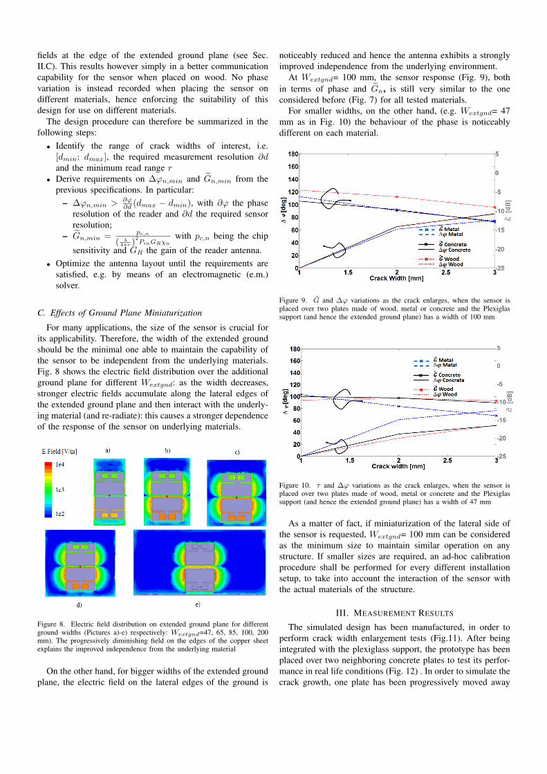
For many applications, the size of the sensor is crucial forits applicability. Therefore, the width of the extended groundshould be the minimal one able to maintain the capability ofthe sensor to be independent from the underlying materials.Fig. 8 shows the electric field distribution over the additionalground plane for different Wextgnd: as the width decreases,stronger electric fields accumulate along the lateral edges ofthe extended ground plane and then interact with the underly-ing material (and re-radiate): this causes a stronger dependenceof the response of the sensor on underlying materials.
Figure 8. Electric field distribution on extended ground plane for differentground widths (Pictures a)-e) respectively: Wextgnd=47, 65, 85, 100, 200mm). The progressively diminishing field on the edges of the copper sheetexplains the improved independence from the underlying material
On the other hand, for bigger widths of the extended groundplane, the electric field on the lateral edges of the ground is
noticeably reduced and hence the antenna exhibits a stronglyimproved independence from the underlying environment.
At Wextgnd= 100 mm, the sensor response (Fig. 9), bothin terms of phase and Gn, is still very similar to the oneconsidered before (Fig. 7) for all tested materials.
For smaller widths, on the other hand, (e.g. Wextgnd= 47mm as in Fig. 10) the behaviour of the phase is noticeablydifferent on each material.
Figure 9. G and ∆ϕ variations as the crack enlarges, when the sensor isplaced over two plates made of wood, metal or concrete and the Plexiglassupport (and hence the extended ground plane) has a width of 100 mm
Figure 10. τ and ∆ϕ variations as the crack enlarges, when the sensor isplaced over two plates made of wood, metal or concrete and the Plexiglassupport (and hence the extended ground plane) has a width of 47 mm
As a matter of fact, if miniaturization of the lateral side ofthe sensor is requested, Wextgnd= 100 mm can be consideredas the minimum size to maintain similar operation on anystructure. If smaller sizes are required, an ad-hoc calibrationprocedure shall be performed for every different installationsetup, to take into account the interaction of the sensor withthe actual materials of the structure.
III. MEASUREMENT RESULTS
The simulated design has been manufactured, in order toperform crack width enlargement tests (Fig.11). After beingintegrated with the plexiglass support, the prototype has beenplaced over two neighboring concrete plates to test its perfor-mance in real life conditions (Fig. 12) . In order to simulate thecrack growth, one plate has been progressively moved away
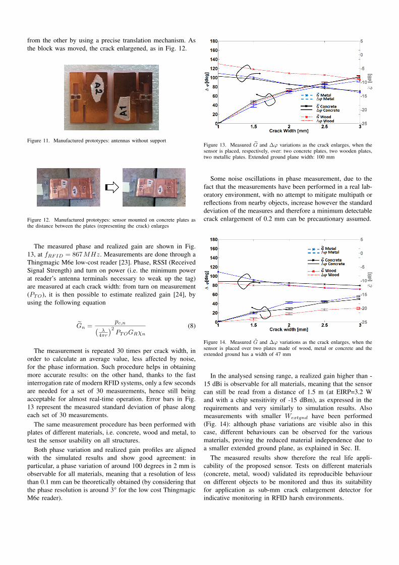
from the other by using a precise translation mechanism. Asthe block was moved, the crack enlargened, as in Fig. 12.
Figure 11. Manufactured prototypes: antennas without support
Figure 12. Manufactured prototypes: sensor mounted on concrete plates asthe distance between the plates (representing the crack) enlarges
The measured phase and realized gain are shown in Fig.13, at fRFID = 867MHz. Measurements are done through aThingmagic M6e low-cost reader [23]. Phase, RSSI (ReceivedSignal Strength) and turn on power (i.e. the minimum powerat reader’s antenna terminals necessary to weak up the tag)are measured at each crack width: from turn on measurement(PTO), it is then possible to estimate realized gain [24], byusing the following equation
Gn =pc,n(
λ4πr
)2PTOGRχn
(8)
The measurement is repeated 30 times per crack width, inorder to calculate an average value, less affected by noise,for the phase information. Such procedure helps in obtainingmore accurate results: on the other hand, thanks to the fastinterrogation rate of modern RFID systems, only a few secondsare needed for a set of 30 measurements, hence still beingacceptable for almost real-time operation. Error bars in Fig.13 represent the measured standard deviation of phase alongeach set of 30 measurements.
The same measurement procedure has been performed withplates of different materials, i.e. concrete, wood and metal, totest the sensor usability on all structures.
Both phase variation and realized gain profiles are alignedwith the simulated results and show good agreement: inparticular, a phase variation of around 100 degrees in 2 mm isobservable for all materials, meaning that a resolution of lessthan 0.1 mm can be theoretically obtained (by considering thatthe phase resolution is around 3° for the low cost ThingmagicM6e reader).
Figure 13. Measured G and ∆ϕ variations as the crack enlarges, when thesensor is placed, respectively, over: two concrete plates, two wooden plates,two metallic plates. Extended ground plane width: 100 mm
Some noise oscillations in phase measurement, due to thefact that the measurements have been performed in a real lab-oratory environment, with no attempt to mitigate multipath orreflections from nearby objects, increase however the standarddeviation of the measures and therefore a minimum detectablecrack enlargement of 0.2 mm can be precautionary assumed.
Figure 14. Measured G and ∆ϕ variations as the crack enlarges, when thesensor is placed over two plates made of wood, metal or concrete and theextended ground has a width of 47 mm
In the analysed sensing range, a realized gain higher than -15 dBi is observable for all materials, meaning that the sensorcan still be read from a distance of 1.5 m (at EIRP=3.2 Wand with a chip sensitivity of -15 dBm), as expressed in therequirements and very similarly to simulation results. Alsomeasurements with smaller Wextgnd have been performed(Fig. 14): although phase variations are visible also in thiscase, different behaviours can be observed for the variousmaterials, proving the reduced material independence due toa smaller extended ground plane, as explained in Sec. II.
The measured results show therefore the real life appli-cability of the proposed sensor. Tests on different materials(concrete, metal, wood) validated its reproducible behaviouron different objects to be monitored and thus its suitabilityfor application as sub-mm crack enlargement detector forindicative monitoring in RFID harsh environments.
IV. CONCLUSION
The possibility to monitor crack progression on concretestructures by means of a passive RFID based wireless sensorsystem has been here demonstrated and validated, both bysimulation and laboratory measurement. A trade-off betweencommunication capabilities and crack enlargement sensitivityhas been shown by means of a parametric design method, en-abling good sensing with limited communication degradation.Good agreement between simulated and measured results isfound when the sensor is placed on concrete structures, aswell as on various other materials, proving that the proposedsensor is usable as a generic wireless crack meter. Differentapplications are foreseeable, such as monitoring of concretewalls in ancient buildings or metallic frameworks in bridgesor aeronautic structures. The proposed system is designed for1D crack enlargement: more complicated structures, able toslide on two orthogonal planes, can be also foreseen.
Due to the use of phase as sensing parameter, some mea-surement precautions have been adopted: on the one hand,multiple measurement samples for each crack width diminishthe effects of spurious noise on phase and hence help inachieving more accurate read-outs, without nevertheless im-pacting drastically on the total measuring time, i.e. allowingfor almost real-time measurement. On the other hand, thesystem is dependent on the distance between reader and tagsand therefore a fixed measurement setup was employed, so thatthe distance and orientation between reader and tags do notvary all along the sensing process. Such constraint is howevernot limiting in many test environments, where the monitoringinfrastructure can be considered fixed. A setup independentphase parameter is an open issue for further research, alreadybeing tackled by the authors.
REFERENCES
[1] P.C. Chang, A. Flatau, S.C. Liu, “Review paper: health monitoring ofcivil infrastructure”, Structural Health Monitoring, vol. 2, no. 3, pp.257-267, Sept. 2003
[2] Encyclopedia of Structural Health Monitoring, John Wiley and Sons,Inc., 2014 DOI: 10.1002/9780470061626
[3] F. Ravet, F. Briffod, B. Glisic, M. Nikles, D. Inaudi, "Submillimetercrack detection with Brillouin-based fiber-optic sensors", IEEE SensorsJ., vol. 9, no. 11, pp. 1391-1397, Nov. 2009
[4] M. Ramakrishnan, G. Rajan, Y. Semenova, G. Farrell, "Hybrid fiber opticsensor system for measuring the strain, temperature and thermal strainof composite materials", IEEE Sensors J., vol. 14, no. 8, pp. 2571-2578,Aug. 2014
[5] J. P. Lynch, K. J. Loh, “A summary review of wireless sensors andsensor networks for structural health monitoring”, Shock Vib. Dig., vol.38, pp. 91–128, 2006.
[6] A. Ledeczi, T. Hay, P. Volgyesi, D. R. Hay, A. Nadas, S. Jayaraman,"Wireless acoustic emission sensor network for structural monitoring",IEEE Sensors J., vol. 9, no. 11, pp. 1370-1377, Nov. 2009
[7] P. Kalansuriya, R. Bhattacharyya, S. Sarma, "RFID tag antenna-basedsensing for pervasive surface crack detection", IEEE Sensors J., vol. 13,no. 5, pp. 1564-1570, May 2013
[8] A. Deivasigamani, A. Daliri, C. Wang, and S. John, ’A review of passivewireless sensors for structural health monitoring’, Modern AppliedScience, vol. 7, no. 2, pp. 57-76, 2013
[9] S. Deshmukh, H. Huang,”Wireless interrogation of passive antennasensors”, Measurement Science and Technology, 21, 035201, 2010
[10] A. Daliri, A. Galehdar, S. John, C.H. Wang, W.S.T. Rowe, K. Ghorbani,“Wireless strain measurement using circular microstrip patch antennas”,Sensors and Actuators A: Physical, 184, 86-92, 2012
[11] C. Mandel, M. Schussler, R. Jakoby, "A wireless passive strain sensor,"IEEE Sensors, vol., no., pp.207,210, 28-31 Oct. 2011
[12] V. Rizzoli, A. Costanzo, E. Montanari, A. Benedetti, "A new wirelessdisplacement sensor based on reverse design of microwave and millime-ter wave antenna array", IEEE Sensors J., vol. 9, no. 11, pp. 1557-1566,Nov. 2009
[13] C. Occhiuzzi, S. Caizzone, G. Marrocco, “Passive UHF RFID antennasfor sensing applications: principles, methods and classifications”, IEEEAntennas Propag. Mag., vol.55, no. 6, pp. 14-34, Dec. 2013
[14] R. Bhattacharyya, C. Floerkemeier, and S. Sarma, “Towards tag antennabased sensing - an RFID displacement sensor,” IEEE 2009 Int. Conf. onRFID, pp. 95 –102, Orlando (USA), Apr. 2009
[15] X. Yi, C. Cho et al., "Wireless strain and crack sensing using a foldedpatch antenna", Proc. of European Conf. on Antennas and Propag.(EUCAP) 2012, Prague (Czech Rep.), Mar. 2012
[16] C. Occhiuzzi, C., Paggi, G. Marrocco, “Passive RFID strain-sensor basedon meander-line antennas”, IEEE Trans. Antennas Propag., 59(12),4836-4840, 2011
[17] S. Caizzone, E. DiGiampaolo, G. Marrocco, “Wireless crack monitoringby stationary phase measurements from coupled RFID tags”, IEEETrans. Antennas Propag. , vol. 62, no. 12, pp. 6412-6419, Dec. 201
[18] S. Manzari, S. Pettinari, G. Marrocco, "Miniaturised wearable UHF-RFID tag with tuning capability," Electronics Letters , vol.48, no.21,pp.1325,1326, Oct. 2012
[19] G. Marrocco, "RFID Grids: Part I—electromagnetic theory," IEEETrans. Antennas Propag. , vol.59, no.3, pp.1019-1026, Mar. 2011
[20] J.C. Bolomey, S. Capdevila, L. Jofre, J. Romeu, "ElectromagneticModeling of RFID-Modulated Scattering Mechanism. Application toTag Performance Evaluation," Proc. of the IEEE , vol. 98, no. 9, pp.1555-1569, Sept. 2010
[21] S. Capdevila, L. Jofre, J. Romeu, J.C. Bolomey, "Efficient ParametricCharacterization of the Dynamic Performance of an RFID IC", IEEEMicrowave and Wireless Comp. Letters, vol. 22, no. 8, pp. 436-438,Aug. 2012
[22] J.D. Griffin, G. D. Durgin, "Complete Link Budgets for Backscatter-Radio and RFID Systems", IEEE Antennas Prop. Mag., vol. 51, no. 2,pp. 11-26, Apr. 2009
[23] Datasheet M6e High Performance 4-Port UHF RFID module. Available:www.thingmagic.com
[24] S. Caizzone, G. Marrocco, "RFID Grids: Part II—experimentations,"IEEE Trans. Antennas Propag. , vol.59, no.8, Aug. 2011