Embed Size (px)
Citation preview
Wireless Networks (ECE 645) Final Project
Project by GROUP -5,
Fatema Zohora ID#31256141
Sai Dheera Dyuti Gundu ID#31262669
Vinodh Jerald Shekar ID#31328835
Pankitkumar Khant ID#31264973
Under the guidance of,
Dr. Byron Chen Date of Submission: 05/11/2015
ii
Table of Contents
List of Figures ................................................................................................................................ iv
List of Tables ................................................................................................................................. iv
Chapter 1 - GEO-LOCATION........................................................................................................ 1
1.2 Evolution and History ........................................................................................................... 1
1.3 Applications .......................................................................................................................... 2
Chapter 2 - LTE ARCHITECTURE ............................................................................................... 3
1.1 Overview of LTE Architecture ............................................................................................. 3
1.1.1 Evolved UMTS Radio Access Network/E-UTRAN ...................................................... 3
1.1.2 Evolved Packet Core ...................................................................................................... 3
1.2 LTE Radio Protocol Architecture ......................................................................................... 4
1.2.1 User Plane ...................................................................................................................... 4
1.2.2 Control Plane ................................................................................................................. 5
1.3 LTE Protocol Layers ............................................................................................................. 5
Chapter 3 - GEOLOCATION IN LTE ........................................................................................... 7
3.1 General Aspects of LTE positioning .................................................................................... 7
3.1.1 Control Plane Positioning .............................................................................................. 7
3.1.2 User Plane Positioning ................................................................................................... 8
3.2 Positioning Protocols in LTE ................................................................................................ 8
3.2.1 LPP – Location Positioning Protocol ............................................................................. 8
3.2.2 SUPL- Secure User Plane Protocol ................................................................................ 8
3.3 LTE Positioning Technologies ............................................................................................. 9
Chapter 4 - INDOOR GEOLOCATION ...................................................................................... 10
4.1 Introduction ............................................................................................................................. 10
4.2 Indoor Geolocation System ................................................................................................ 10
4.2.1 Network Based System Architecture: .......................................................................... 10
4.2.2 Mobile Based System Architecture: ............................................................................ 11
4.3 Indoor Geolocation Measuring Principles and Positioning Algorithm .............................. 11
4.3.1 Triangulation ................................................................................................................ 11
4.3.1.1 Lateration Techniques ........................................................................................... 11
iii
4.3.1.2 Angulation Techniques: ........................................................................................ 14
4.3.2 Scene Analysis: ............................................................................................................ 14
4.4 Indoor Geolocation Wireless Technologies: ....................................................................... 14
4.4.1 GPS –Based: ................................................................................................................ 15
4.4.2 WLAN (IEEE 802.11) ................................................................................................. 15
4.4.3 RFID ............................................................................................................................ 15
4.4.4 UWB ............................................................................................................................ 16
Chapter 5 - GEOLOCATION TECHNOLOGIES ....................................................................... 17
5.1 iOS Geolocation .................................................................................................................. 17
5.1.1 Introduction .................................................................................................................. 17
5.1.2 Example of Location Based Services........................................................................... 17
5.1.3 Privacy Setting ............................................................................................................. 18
5.2 Android Geolocation ........................................................................................................... 18
5.2.1 Introduction .................................................................................................................. 18
5.2.1 Android Application Programming Interface (API) .................................................... 18
5.3 GLONASS System ............................................................................................................. 19
5.4 How Can GLONASS and GPS Work Together? ............................................................... 19
Chapter 6 - CONCLUSION .......................................................................................................... 20
References ..................................................................................................................................... 21
iv
List of Figures
Figure 2.1 Simplified LTE Architecture ......................................................................................... 3
Figure 2.2 Evolved Packet Core ..................................................................................................... 3
Figure 2.3 Classification of Radio Protocol Architecture ............................................................... 4
Figure 2.4 U-Plane Protocol Stack and Entities.............................................................................. 5
Figure 2.5 C-Plane Protocol Stack and Entities .............................................................................. 5
Figure 3.1 LTE LBS Architecture .................................................................................................. 7
Figure 3.2 Control Plane Positioning .............................................................................................. 7
Figure 3.3 User Plane Positioning .................................................................................................. 8
Figure 3.4 E-CID ............................................................................................................................ 9
Figure 3.5 TDOA ............................................................................................................................ 9
Figure 3.6 A-GNSS ......................................................................................................................... 9
Figure 4.1 Overall Architecture of Indoor Geolocation Systems ................................................. 10
Figure 4.2 Indoor Positioning ....................................................................................................... 11
Figure 4.3 TOA ............................................................................................................................. 12
Figure 4.4 TDOA .......................................................................................................................... 12
Figure 4.5 Received Signal Phase ................................................................................................. 13
Figure 4.6 AOA Techniques ......................................................................................................... 14
Figure 4.7 Indoor Geolocation Technologies ............................................................................... 15
Figure 4.8 RFID System ............................................................................................................... 16
Figure 5.1 System Architecture: Enhanced Location Based Services .......................................... 17
Figure 5.2 Android API ................................................................................................................ 18
List of Tables
Table 1.1 Geolocation Categorization ............................................................................................ 2
Table 3.1 Positioning Methods for LTE ......................................................................................... 9
1
Chapter 1 - GEO-LOCATION
Where is one at this very moment? This simple question has always held significant bearing and its
answer, a complex desirability. Be that as it may, a new set of services are making it even more relevant.
Services that can save one money, time and even save one’s life. All of it beginning with just this simple
question and its much desired answer. These new services, called, Location Based Services (LBS) exploit
knowledge about where a service user, typically someone with a mobile information device, is located. And this
collection of a client's location data is broadly known as “Geolocation”. Geolocation may be more formally
defined as "the methodology of discovering, deciding and giving the precise area of a PC, organizing gadget or
gear. It empowers gadget area in light of geological directions and estimations”.
Despite the fact that, geolocation in itself is not a new concept, it hadn’t caught on as a life
complementing service till 2008. But now, life as we know it cannot be imagined without these location based
services. And with the take-off of Long Term Evolution and a rich set of the services it offers being based on
location information, the need to consider geolocation taking into account this 4G innovation is obvious. The
aim of this report is to provide the reader with a basic understanding of the workings of wireless geolocation in
LTE, while also touching upon geolocation as an individual topic. It takes the long route by stating off with a
brief introduction to geolocation in chapter one and further moves on to present certain fundamentals of LTE
architecture that are pertinent to understanding geolocation in chapter two. The third chapter at its core deals
with how geolocation is handled within an LTE network and the various methods of geolocation available
within an LTE network. The fourth chapter focuses on indoor-geolocation, since it is where most time is spent
in today’s world. The fourth chapter focuses on how geo-location is handled by the two giants in the operating
system war, Android and Apple, on their platforms.
1.2 Evolution and History
The conception of geolocation, while not in the same form as it is used today, began many millennia
before. The ancient Greeks were the first to use triangulation to estimate their position with the help of stars,
over 2000 years ago. Between the 1920’s to 1940’s, the Naval Research Laboratory explored the use of radio
waves for detection and ranging of objects and developed what we now call the Radar technology. But, it was
with the launch of the Soviet Union’s ‘Sputnik’ satellite into space that positioning using satellites would come
into existence. The United States Navy capitalized on this idea in 1959 by developing ‘Transit’, a series of six
satellites used to triangulate the position of submarines [1] [2]. The first concrete steps towards the future global
positioning system, a system that relied completely upon satellites for positioning, took place during a meeting
2
in 1973 between heads of the US military and the overall system was decided to be name Navstar Global
Positioning System, or Navstar GPS. Through the 1980s the U.S military mapped out how GPS would function
and serve military purposes. But, by 1983 Ronald Regan the then president of U.S declared GPS for non-
military personnel use to enhance safety [1] [2]. Since then, GPS continued to grow with the first handheld GPS
collector dispatched in 1989. By, 1999 an organization called “Benson Esc” has already dispatched a GPS
phone to serve business purposes. In the year 2000 Google maps debuted into the industry, bringing to the table
a new way of life. A life ruled by accuracy, location pinpoints and location based services. [1][2]
1.3 Applications
Listed in the Table 1.1 are the drivers, applications, enabling technologies and the key issues of
geolocation, categorized according to the markets they are concerned with.
MARKET KEY LOCATION
BASED SERVICE
DRIVERS
KEY LOCATION BASED
SERVICE APPLICATIONS
ENABLING
TECHNOLOGIES
KEY ISSUES
BUSINESS Growth in Mobile
Employees
Desire/need for
constant
Information and
communications
Work force Management
Asset tracking
Manufacturing/Warehousing
Transportation
Health care
GPS
Terrestrial Network-
Based(TDOA)
RFID
Location Enabled
Wi-Fi
Convincing value
propositions
Technology
Convergence
Ease of Adoption
CONSUMER Safety and security
concerns
Continued cellular
penetration and
increasing users
Personal And Family
Tracking ,safety,health
Applications
Social networking
Navigation
GPS
Terrestrial Network-
Based(TDOA)
Location Enabled
Wi-Fi
Privacy
User Interface
,handset platforms
Indoor Performance
PUBLIC
SECTOR
Terrorism
Emergency
communications
disconnects
Emergency communications
Backup to Existing Systems
GPS
Terrestrial Network-
Based(TDOA)
Interoperability
Reliability
Table 1.1 Geolocation Categorization
3
Chapter 2 - LTE ARCHITECTURE
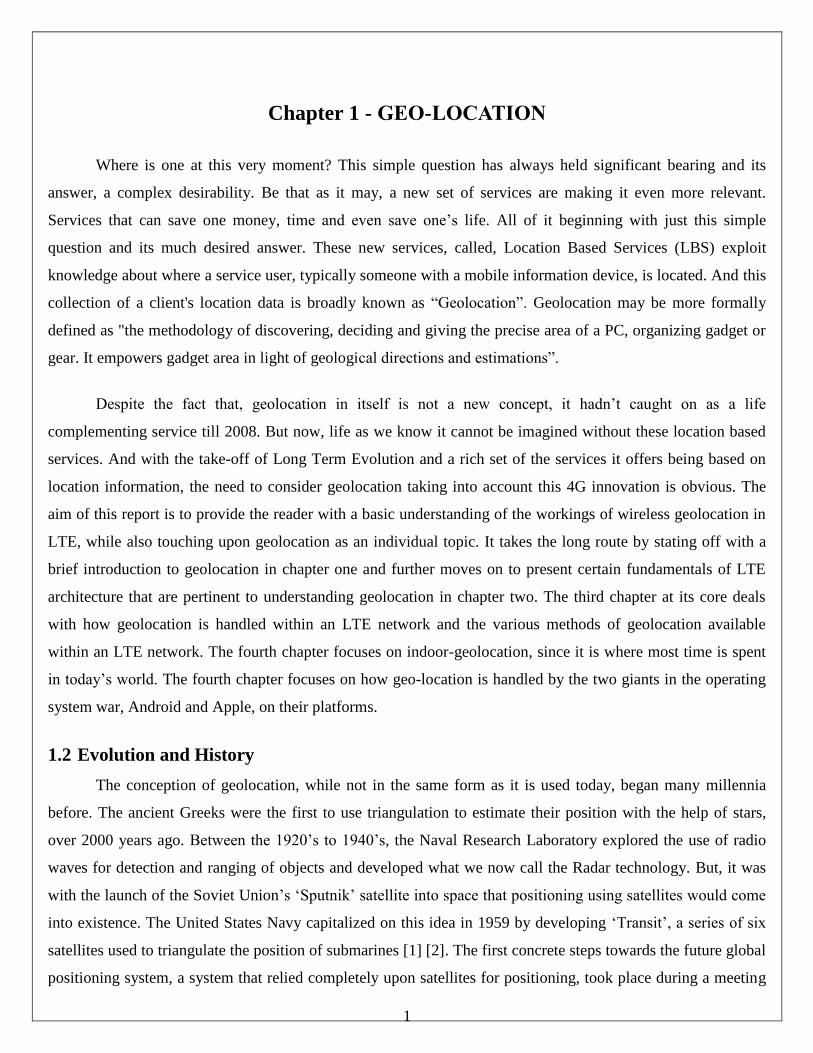
1.1 Overview of LTE Architecture
In contrast to the circuit-switched model of previous cellular systems, Long Term Evolution (LTE) has
been designed to support only packet-switched services. It aims to provide seamless Internet Protocol (IP)
connectivity between user equipment (UE) and the packet data network (PDN), without any disruption to the
end users’ applications during mobility. Below is a simplified version of the LTE architecture which depicts
some of the important components within this Evolved Packet Service (EPS) network.
Figure 2.1 Simplified LTE Architecture [19]
1.1.1 Evolved UMTS Radio Access Network/E-UTRAN
The E-UTRAN is the access part of the Evolved Packet Service (EPS). It handles the radio
communication between the User Equipment and the Evolved Packet Core. The E-UTRAN contains only one
component which are the eNodeB’s. The eNB is the hardware that is connected to the UE which sends and
receive radio transmission signals to and from all its mobiles. They also control low level operations such as
handover commands by sending them signaling information [4].
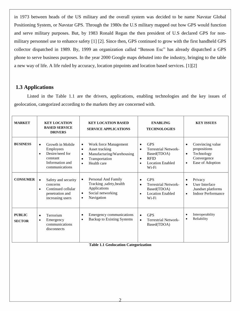
1.1.2 Evolved Packet Core
The EPC is the core network of the LTE system and an evolution of the packet switched architecture
used in GPRS/UMTS. The figure below depicts some of the more important entities within the EPC.
Figure 2.2 Evolved Packet Core [19]
4
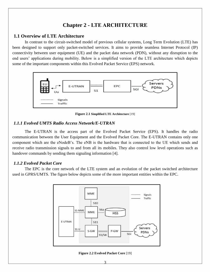
1.2 LTE Radio Protocol Architecture
The task of exchanging information between the network entities requires a high degree of co-operation
between the involved parties. Protocols are a set of rules or conventions that make communication possible and
much easier when the communicating parties adhere to them. The LTE’s layered protocol architecture allows
the protocols and the services they provide to be grouped into a hierarchy of layers. Furthermore, the radio
protocol architecture for LTE can also logically be separated into two planes, the USER PLANE and the
CONTROL PLANE, based on the user data and signaling respectively. This functional split helps the
operators dimension and adapt their network easily.
Figure 2.3 Classification of Radio Protocol Architecture [19]
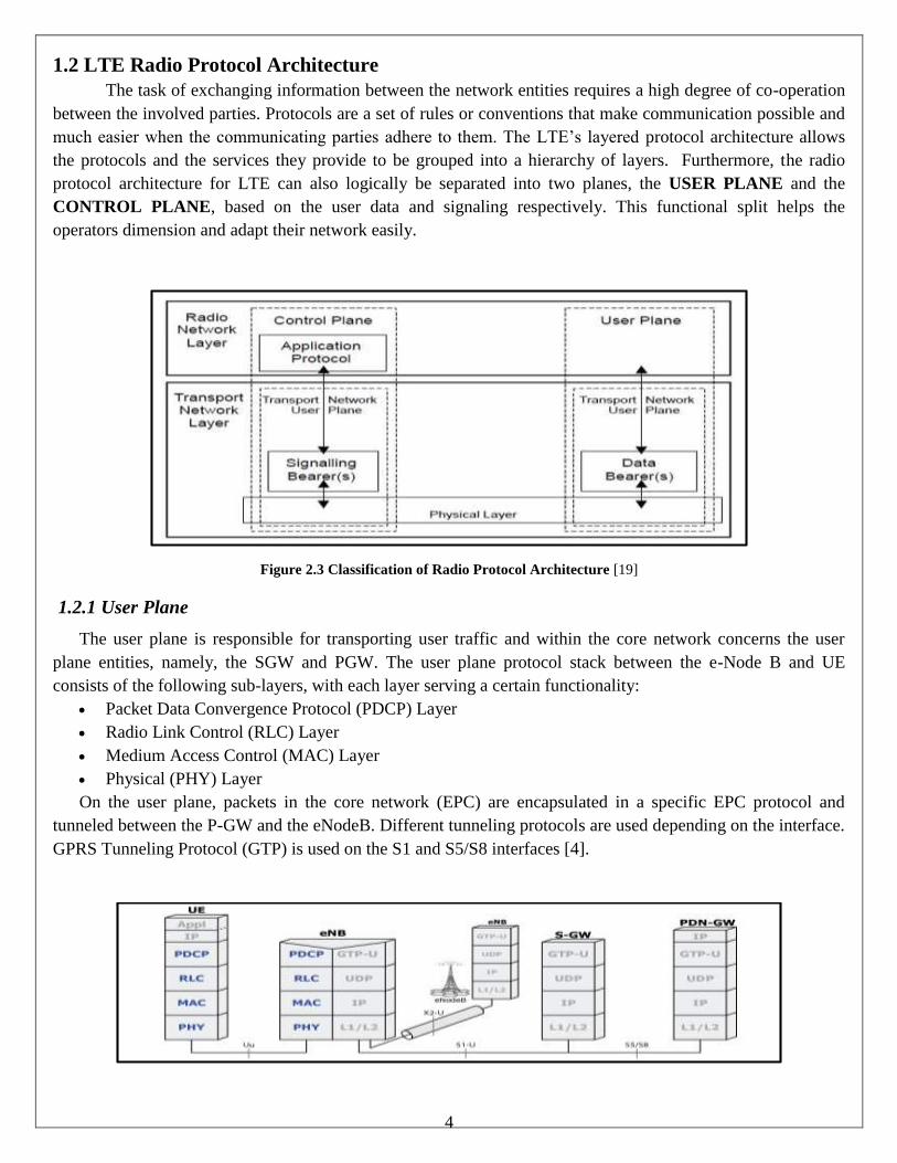
1.2.1 User Plane
The user plane is responsible for transporting user traffic and within the core network concerns the user
plane entities, namely, the SGW and PGW. The user plane protocol stack between the e-Node B and UE
consists of the following sub-layers, with each layer serving a certain functionality:
Packet Data Convergence Protocol (PDCP) Layer
Radio Link Control (RLC) Layer
Medium Access Control (MAC) Layer
Physical (PHY) Layer
On the user plane, packets in the core network (EPC) are encapsulated in a specific EPC protocol and
tunneled between the P-GW and the eNodeB. Different tunneling protocols are used depending on the interface.
GPRS Tunneling Protocol (GTP) is used on the S1 and S5/S8 interfaces [4].
5
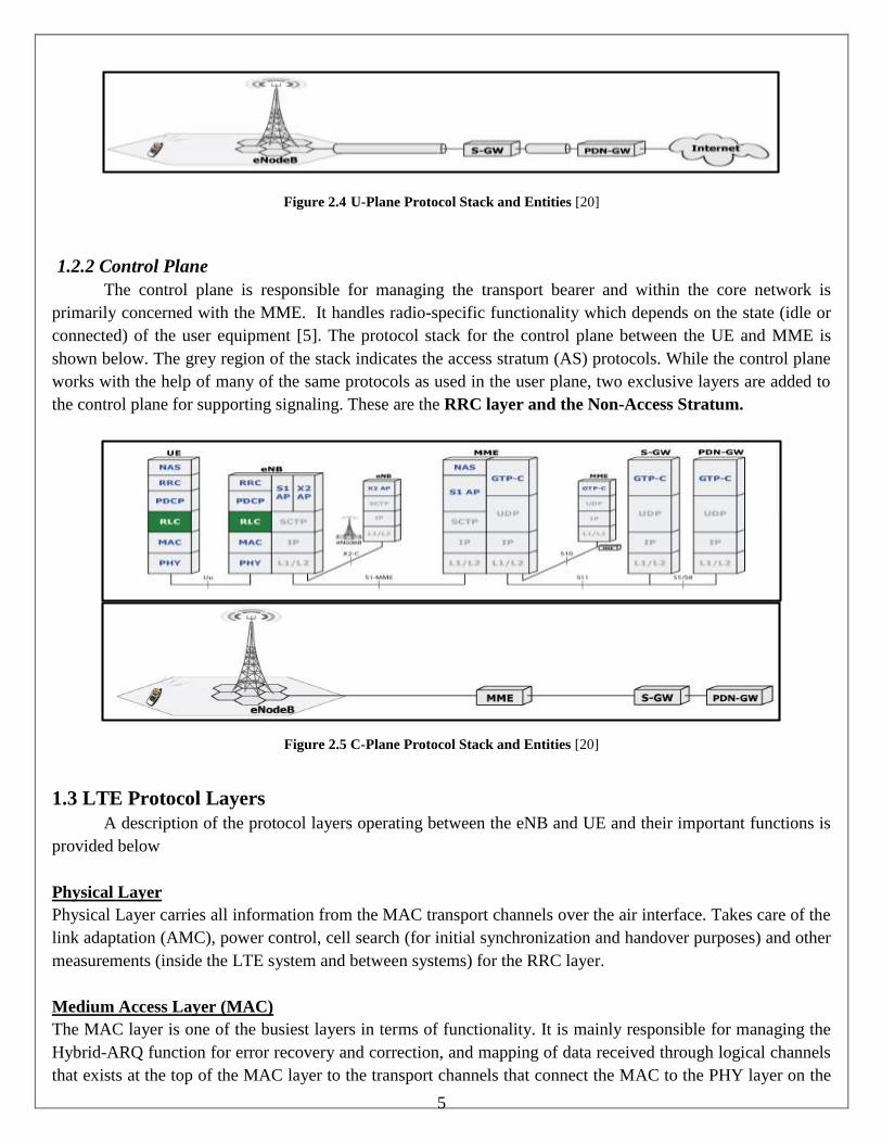
Figure 2.4 U-Plane Protocol Stack and Entities [20]
1.2.2 Control Plane
The control plane is responsible for managing the transport bearer and within the core network is
primarily concerned with the MME. It handles radio-specific functionality which depends on the state (idle or
connected) of the user equipment [5]. The protocol stack for the control plane between the UE and MME is
shown below. The grey region of the stack indicates the access stratum (AS) protocols. While the control plane
works with the help of many of the same protocols as used in the user plane, two exclusive layers are added to
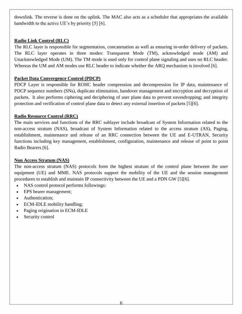
the control plane for supporting signaling. These are the RRC layer and the Non-Access Stratum.
Figure 2.5 C-Plane Protocol Stack and Entities [20]
1.3 LTE Protocol Layers
A description of the protocol layers operating between the eNB and UE and their important functions is
provided below
Physical Layer
Physical Layer carries all information from the MAC transport channels over the air interface. Takes care of the
link adaptation (AMC), power control, cell search (for initial synchronization and handover purposes) and other
measurements (inside the LTE system and between systems) for the RRC layer.
Medium Access Layer (MAC)
The MAC layer is one of the busiest layers in terms of functionality. It is mainly responsible for managing the
Hybrid-ARQ function for error recovery and correction, and mapping of data received through logical channels
that exists at the top of the MAC layer to the transport channels that connect the MAC to the PHY layer on the
6
downlink. The reverse is done on the uplink. The MAC also acts as a scheduler that appropriates the available
bandwidth to the active UE’s by priority [5] [6].
Radio Link Control (RLC)
The RLC layer is responsible for segmentation, concatenation as well as ensuring in-order delivery of packets.
The RLC layer operates in three modes: Transparent Mode (TM), acknowledged mode (AM) and
Unacknowledged Mode (UM). The TM mode is used only for control plane signaling and uses no RLC header.
Whereas the UM and AM modes use RLC header to indicate whether the ARQ mechanism is involved [6].
Packet Data Convergence Control (PDCP)
PDCP Layer is responsible for ROHC header compression and decompression for IP data, maintenance of
PDCP sequence numbers (SNs), duplicate elimination, handover management and encryption and decryption of
packets. It also performs ciphering and deciphering of user plane data to prevent eavesdropping; and integrity
protection and verification of control plane data to detect any external insertion of packets [5][6].
Radio Resource Control (RRC)
The main services and functions of the RRC sublayer include broadcast of System Information related to the
non-access stratum (NAS), broadcast of System Information related to the access stratum (AS), Paging,
establishment, maintenance and release of an RRC connection between the UE and E-UTRAN, Security
functions including key management, establishment, configuration, maintenance and release of point to point
Radio Bearers [6].
Non Access Stratum (NAS)
The non-access stratum (NAS) protocols form the highest stratum of the control plane between the user
equipment (UE) and MME. NAS protocols support the mobility of the UE and the session management
procedures to establish and maintain IP connectivity between the UE and a PDN GW [5][6].
NAS control protocol performs followings:
EPS bearer management;
Authentication;
ECM-IDLE mobility handling;
Paging origination in ECM-IDLE
Security control
7
Chapter 3 - GEOLOCATION IN LTE
3.1 General Aspects of LTE positioning
The positioning methods in LTE rely on the high level network architecture. There are three main elements
involved in the process, the Location Service Client (LCS), the LCS Server (LS) and the LCS Target. A client is
predominantly the application requesting the location services and is available on the LCS target. This service
obtains the location information by sending a request to the server. The location server is a physical or logical entity
that collects measurements and other location information from the device and base station and assists the device
with measurements and estimating its position. The server basically processes the request from the client and
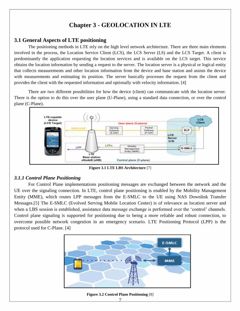
provides the client with the requested information and optionally with velocity information. [4]
There are two different possibilities for how the device (client) can communicate with the location server.
There is the option to do this over the user plane (U-Plane), using a standard data connection, or over the control
plane (C-Plane).
Figure 3.1 LTE LBS Architecture [7]
3.1.1 Control Plane Positioning
For Control Plane implementations positioning messages are exchanged between the network and the
UE over the signaling connection. In LTE, control plane positioning is enabled by the Mobility Management
Entity (MME), which routes LPP messages from the E-SMLC to the UE using NAS Downlink Transfer
Messages.[5] The E-SMLC (Evolved Serving Mobile Location Center) is of relevance as location server and
when a LBS session is established, assistance data message exchange is performed over the ‘control’ channels.
Control plane signaling is supported for positioning due to being a more reliable and robust connection, to
overcome possible network congestion in an emergency scenario. LTE Positioning Protocol (LPP) is the
protocol used for C-Plane. [4]
Figure 3.2 Control Plane Positioning [8]
8
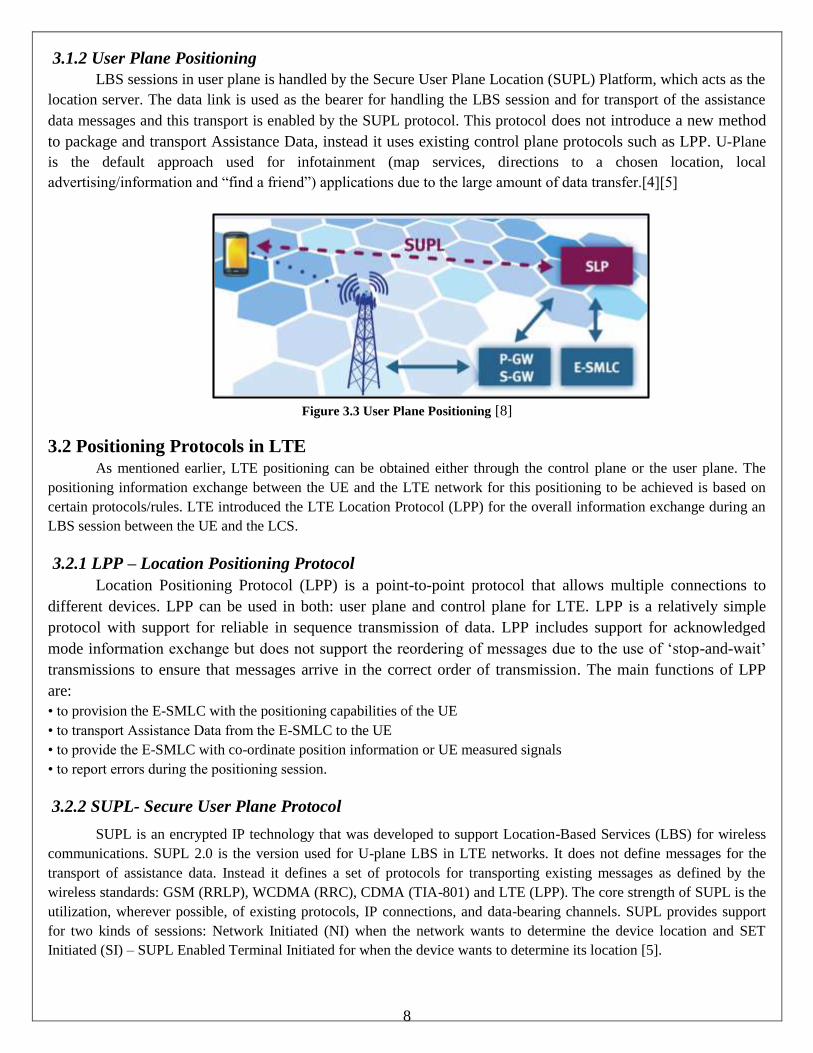
3.1.2 User Plane Positioning
LBS sessions in user plane is handled by the Secure User Plane Location (SUPL) Platform, which acts as the
location server. The data link is used as the bearer for handling the LBS session and for transport of the assistance
data messages and this transport is enabled by the SUPL protocol. This protocol does not introduce a new method
to package and transport Assistance Data, instead it uses existing control plane protocols such as LPP. U-Plane
is the default approach used for infotainment (map services, directions to a chosen location, local
advertising/information and “find a friend”) applications due to the large amount of data transfer.[4][5]
Figure 3.3 User Plane Positioning [8]
3.2 Positioning Protocols in LTE As mentioned earlier, LTE positioning can be obtained either through the control plane or the user plane. The
positioning information exchange between the UE and the LTE network for this positioning to be achieved is based on
certain protocols/rules. LTE introduced the LTE Location Protocol (LPP) for the overall information exchange during an
LBS session between the UE and the LCS.
3.2.1 LPP – Location Positioning Protocol
Location Positioning Protocol (LPP) is a point-to-point protocol that allows multiple connections to
different devices. LPP can be used in both: user plane and control plane for LTE. LPP is a relatively simple
protocol with support for reliable in sequence transmission of data. LPP includes support for acknowledged
mode information exchange but does not support the reordering of messages due to the use of ‘stop-and-wait’
transmissions to ensure that messages arrive in the correct order of transmission. The main functions of LPP
are:
• to provision the E-SMLC with the positioning capabilities of the UE
• to transport Assistance Data from the E-SMLC to the UE
• to provide the E-SMLC with co-ordinate position information or UE measured signals
• to report errors during the positioning session.
3.2.2 SUPL- Secure User Plane Protocol
SUPL is an encrypted IP technology that was developed to support Location-Based Services (LBS) for wireless
communications. SUPL 2.0 is the version used for U-plane LBS in LTE networks. It does not define messages for the
transport of assistance data. Instead it defines a set of protocols for transporting existing messages as defined by the
wireless standards: GSM (RRLP), WCDMA (RRC), CDMA (TIA-801) and LTE (LPP). The core strength of SUPL is the
utilization, wherever possible, of existing protocols, IP connections, and data-bearing channels. SUPL provides support
for two kinds of sessions: Network Initiated (NI) when the network wants to determine the device location and SET
Initiated (SI) – SUPL Enabled Terminal Initiated for when the device wants to determine its location [5].
9
Figure 3.5 TDOA [8]
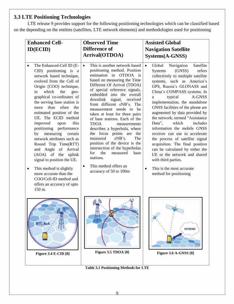
3.3 LTE Positioning Technologies
LTE release 9 provides support for the following positioning technologies which can be classified based
on the depending on the entities (satellites, LTE network elements) and methodologies used for positioning
Enhanced Cell-
ID(ECID)
Observed Time
Difference of
Arrival(OTDOA)
Assisted Global
Navigation Satellite
Systems(A-GNSS)
The Enhanced-Cell ID (E-
CID) positioning is a
network based technique,
evolved from the Cell of
Origin (COO) technique,
in which the geo-
graphical co-ordinates of
the serving base station is
more than often the
estimated position of the
UE. The ECID method
improved upon this
positioning performance
by measuring certain
network attributes such as
Round Trip Time(RTT)
and Angle of Arrival
(AOA) of the uplink
signal to position the UE.
This method is slightly
more accurate than the
COO/Cell-ID method and
offers an accuracy of upto
150 m.
This is another network based
positioning method. Position
estimation in OTDOA is
based on measuring the Time
Different Of Arrival (TDOA)
of special reference signals,
embedded into the overall
downlink signal, received
from different eNB’s. The
measurement needs to be
taken at least for three pairs
of base stations. Each of the
TDOA measurements
describes a hyperbola, where
the focus points are the
measured eNB’s. The
position of the device is the
intersection of the hyperbolas
for the measured base
stations.
This method offers an
accuracy of 50 to 100m
Global Navigation Satellite
Systems (GNSS) refers
collectively to multiple satellite
systems, such as America’s
GPS, Russia’s GLONASS and
China’s COMPASS systems. In
a typical A-GNSS
implementation, the standalone
GNSS facilities of the phone are
augmented by data provided by
the network, termed “Assistance
Data”, which includes
information the mobile GNSS
receiver can use to accelerate
the process of satellite signal
acquisition. The final position
can be calculated by either the
UE or the network and shared
with third parties.
This is the most accurate
method for positioning
Table 3.1 Positioning Methods for LTE
Figure 3.4 E-CID [8] Figure 3.6 A-GNSS [8]

10
Chapter 4 - INDOOR GEOLOCATION
4.1 Introduction An indoor geolocation system is a geolocation system that operates indoors. Indoor geolocation systems
have emerged as a means to render localization and navigation inside buildings to people and personnel due to
limited capabilities of outdoor systems in such environments. Indoor location sensing systems have become
very popular in recent years.
Since wireless information access is now widely available, there is a high demand for accurate positioning in
wireless networks, including indoor and outdoor environments. The process of determining a location is called
location sensing, geolocation, position location, or radiolocation, if it uses wireless technologies.
4.2 Indoor Geolocation System
Similar to the cellular geolocation system, the architecture of indoor geolocation systems can be roughly
grouped into two main categories: mobile-based architecture and network-based architecture.
4.2.1 Network Based System Architecture:
Most of the indoor geolocation applications proposed to date have been focused on network-based
system architecture as shown in Fig. 1
Figure 4.1 Overall Architecture of Indoor Geolocation Systems [10]
The geolocation base stations (GBS) extract location metrics from the radio signals transmitted by the
mobile station and relay the information to a geolocation control station (GCS). The connection between GBS
and GCS can be either wired or wireless. Then the position of the mobile station is estimated, displayed and
tracked at the GCS. [10]
Indoor Geolocation System
Network Based
Architecture
Mobile Based
Architecture
11
4.2.2 Mobile Based System Architecture:
With the mobile-based system architecture, the mobile station estimates self-position by measuring
received radio signals from multiple fixed GBS. Compared to mobile-based architecture, the network-based
system has the advantage that the mobile station can be implemented as a simple structured transceiver with
small size and low power consumption that can be easily carried by people or attached to valuable equipment as
a tag. [10]
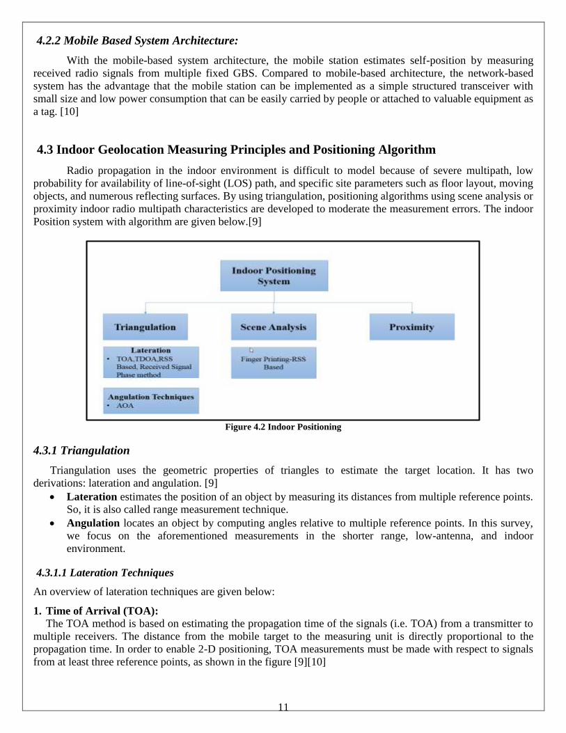
4.3 Indoor Geolocation Measuring Principles and Positioning Algorithm
Radio propagation in the indoor environment is difficult to model because of severe multipath, low
probability for availability of line-of-sight (LOS) path, and specific site parameters such as floor layout, moving
objects, and numerous reflecting surfaces. By using triangulation, positioning algorithms using scene analysis or
proximity indoor radio multipath characteristics are developed to moderate the measurement errors. The indoor
Position system with algorithm are given below.[9]
Figure 4.2 Indoor Positioning
4.3.1 Triangulation
Triangulation uses the geometric properties of triangles to estimate the target location. It has two
derivations: lateration and angulation. [9]
Lateration estimates the position of an object by measuring its distances from multiple reference points.
So, it is also called range measurement technique.
Angulation locates an object by computing angles relative to multiple reference points. In this survey,
we focus on the aforementioned measurements in the shorter range, low-antenna, and indoor
environment.
4.3.1.1 Lateration Techniques
An overview of lateration techniques are given below:
1. Time of Arrival (TOA): The TOA method is based on estimating the propagation time of the signals (i.e. TOA) from a transmitter to
multiple receivers. The distance from the mobile target to the measuring unit is directly proportional to the
propagation time. In order to enable 2-D positioning, TOA measurements must be made with respect to signals
from at least three reference points, as shown in the figure [9][10]
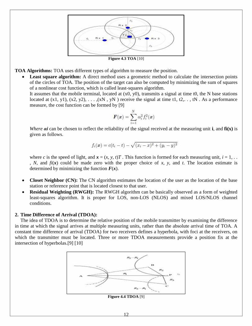
12
Figure 4.3 TOA [10]
TOA Algorithms: TOA uses different types of algorithm to measure the position.
Least square algorithm: A direct method uses a geometric method to calculate the intersection points
of the circles of TOA. The position of the target can also be computed by minimizing the sum of squares
of a nonlinear cost function, which is called least-squares algorithm.
It assumes that the mobile terminal, located at (x0, y0), transmits a signal at time t0, the N base stations
located at (x1, y1), (x2, y2), . . . ,(xN , yN ) receive the signal at time t1, t2,. . , tN . As a performance
measure, the cost function can be formed by [9]
Where αi can be chosen to reflect the reliability of the signal received at the measuring unit i, and fi(x) is
given as follows.
where c is the speed of light, and x = (x, y, t)T . This function is formed for each measuring unit, i = 1, . .
, N, and fi(x) could be made zero with the proper choice of x, y, and t. The location estimate is
determined by minimizing the function F(x).
Closet Neighbor (CN): The CN algorithm estimates the location of the user as the location of the base
station or reference point that is located closest to that user.
Residual Weighting (RWGH): The RWGH algorithm can be basically observed as a form of weighted
least-squares algorithm. It is proper for LOS, non-LOS (NLOS) and mixed LOS/NLOS channel
conditions.
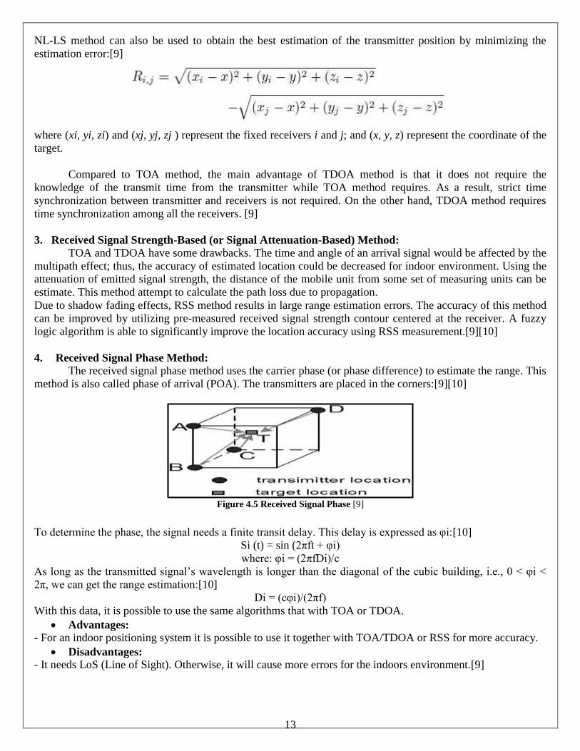
2. Time Difference of Arrival (TDOA): The idea of TDOA is to determine the relative position of the mobile transmitter by examining the difference
in time at which the signal arrives at multiple measuring units, rather than the absolute arrival time of TOA. A
constant time difference of arrival (TDOA) for two receivers defines a hyperbola, with foci at the receivers, on
which the transmitter must be located. Three or more TDOA measurements provide a position fix at the
intersection of hyperbolas.[9] [10]
Figure 4.4 TDOA [9]
13
NL-LS method can also be used to obtain the best estimation of the transmitter position by minimizing the
estimation error:[9]
where (xi, yi, zi) and (xj, yj, zj ) represent the fixed receivers i and j; and (x, y, z) represent the coordinate of the
target.
Compared to TOA method, the main advantage of TDOA method is that it does not require the
knowledge of the transmit time from the transmitter while TOA method requires. As a result, strict time
synchronization between transmitter and receivers is not required. On the other hand, TDOA method requires
time synchronization among all the receivers. [9]
3. Received Signal Strength-Based (or Signal Attenuation-Based) Method:
TOA and TDOA have some drawbacks. The time and angle of an arrival signal would be affected by the
multipath effect; thus, the accuracy of estimated location could be decreased for indoor environment. Using the
attenuation of emitted signal strength, the distance of the mobile unit from some set of measuring units can be
estimate. This method attempt to calculate the path loss due to propagation.
Due to shadow fading effects, RSS method results in large range estimation errors. The accuracy of this method
can be improved by utilizing pre-measured received signal strength contour centered at the receiver. A fuzzy
logic algorithm is able to significantly improve the location accuracy using RSS measurement.[9][10]
4. Received Signal Phase Method:
The received signal phase method uses the carrier phase (or phase difference) to estimate the range. This
method is also called phase of arrival (POA). The transmitters are placed in the corners:[9][10]
Figure 4.5 Received Signal Phase [9]
To determine the phase, the signal needs a finite transit delay. This delay is expressed as φi:[10]
Si (t) = sin (2πft + φi)
where: φi = (2πfDi)/c
As long as the transmitted signal’s wavelength is longer than the diagonal of the cubic building, i.e., 0 < φi <
2π, we can get the range estimation:[10]
Di = (cφi)/(2πf)
With this data, it is possible to use the same algorithms that with TOA or TDOA.
Advantages:
- For an indoor positioning system it is possible to use it together with TOA/TDOA or RSS for more accuracy.
Disadvantages:
- It needs LoS (Line of Sight). Otherwise, it will cause more errors for the indoors environment.[9]
14
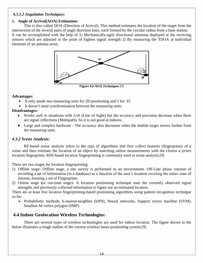
4.3.1.2 Angulation Techniques:
1. Angle of Arrival(AOA) Estimation:
This is also called DOA (Direction of Arrival). This method estimates the location of the target from the
intersection of the several pairs of angle direction lines, each formed by the circular radius from a base station.
It can be accomplished with the help of 1) Mechanically-agile directional antennas deployed at the receiving
sensors which are adjusted to the point of highest signal strength 2) By measuring the TDOA at individual
elements of an antenna array.
Figure 4.6 AOA Techniques [9]
Advantages:
It only needs two measuring units for 2D positioning and 3 for ·D.
It doesn’t need synchronization between the measuring units.
Disadvantages:
Works well in situations with LoS (Line of Sight) but the accuracy and precision decrease when there
are signal reflections (Multipath). So it is not good at indoors.
Large and complex hardware - The accuracy also decreases when the mobile target moves further from
the measuring units
4.3.2 Scene Analysis:
RF-based scene analysis refers to the type of algorithms that first collect features (fingerprints) of a
scene and then estimate the location of an object by matching online measurements with the closest a priori
location fingerprints. RSS-based location fingerprinting is commonly used in scene analysis.[9]
There are two stages for location fingerprinting:
1) Offline stage- Offline stage, a site survey is performed in an environment. Off-Line phase consists of
recording a set of Information (in a database) as a function of the user’s location covering the entire zone of
interest, forming a set of Fingerprints
2) Online stage (or run-time stage)- A location positioning technique uses the currently observed signal
strengths and previously collected information to figure out an estimated location.
There are at least five location fingerprinting-based positioning algorithms using pattern recognition technique
so far:
Probabilistic methods, k-nearest-neighbor (kNN), Neural networks, Support vector machine (SVM),
Smallest M-vertex polygon (SMP)
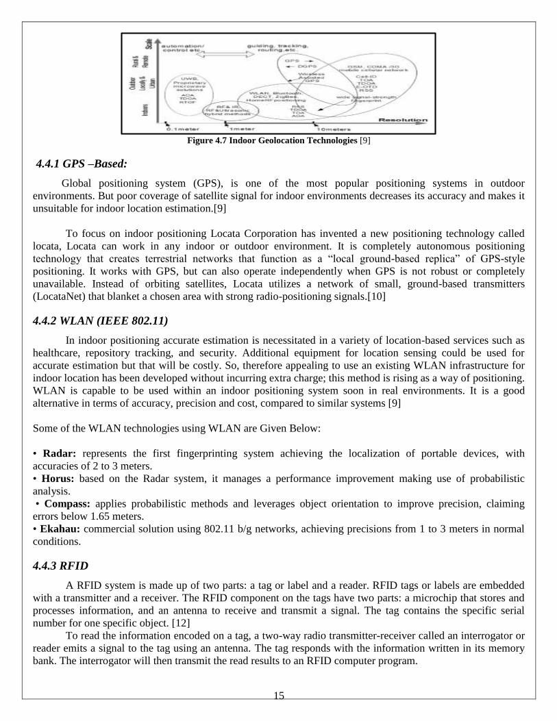
4.4 Indoor Geolocation Wireless Technologies:
There are several types of wireless technologies are used for indoor location. The figure shown in the
below illustrates a rough outline of the current wireless bases positioning system:[9]
15
Figure 4.7 Indoor Geolocation Technologies [9]
4.4.1 GPS –Based:
Global positioning system (GPS), is one of the most popular positioning systems in outdoor
environments. But poor coverage of satellite signal for indoor environments decreases its accuracy and makes it
unsuitable for indoor location estimation.[9]
To focus on indoor positioning Locata Corporation has invented a new positioning technology called
locata, Locata can work in any indoor or outdoor environment. It is completely autonomous positioning
technology that creates terrestrial networks that function as a “local ground-based replica” of GPS-style
positioning. It works with GPS, but can also operate independently when GPS is not robust or completely
unavailable. Instead of orbiting satellites, Locata utilizes a network of small, ground-based transmitters
(LocataNet) that blanket a chosen area with strong radio-positioning signals.[10]
4.4.2 WLAN (IEEE 802.11)
In indoor positioning accurate estimation is necessitated in a variety of location-based services such as
healthcare, repository tracking, and security. Additional equipment for location sensing could be used for
accurate estimation but that will be costly. So, therefore appealing to use an existing WLAN infrastructure for
indoor location has been developed without incurring extra charge; this method is rising as a way of positioning.
WLAN is capable to be used within an indoor positioning system soon in real environments. It is a good
alternative in terms of accuracy, precision and cost, compared to similar systems [9]
Some of the WLAN technologies using WLAN are Given Below:
• Radar: represents the first fingerprinting system achieving the localization of portable devices, with
accuracies of 2 to 3 meters.
• Horus: based on the Radar system, it manages a performance improvement making use of probabilistic
analysis.
• Compass: applies probabilistic methods and leverages object orientation to improve precision, claiming
errors below 1.65 meters.
• Ekahau: commercial solution using 802.11 b/g networks, achieving precisions from 1 to 3 meters in normal
conditions.
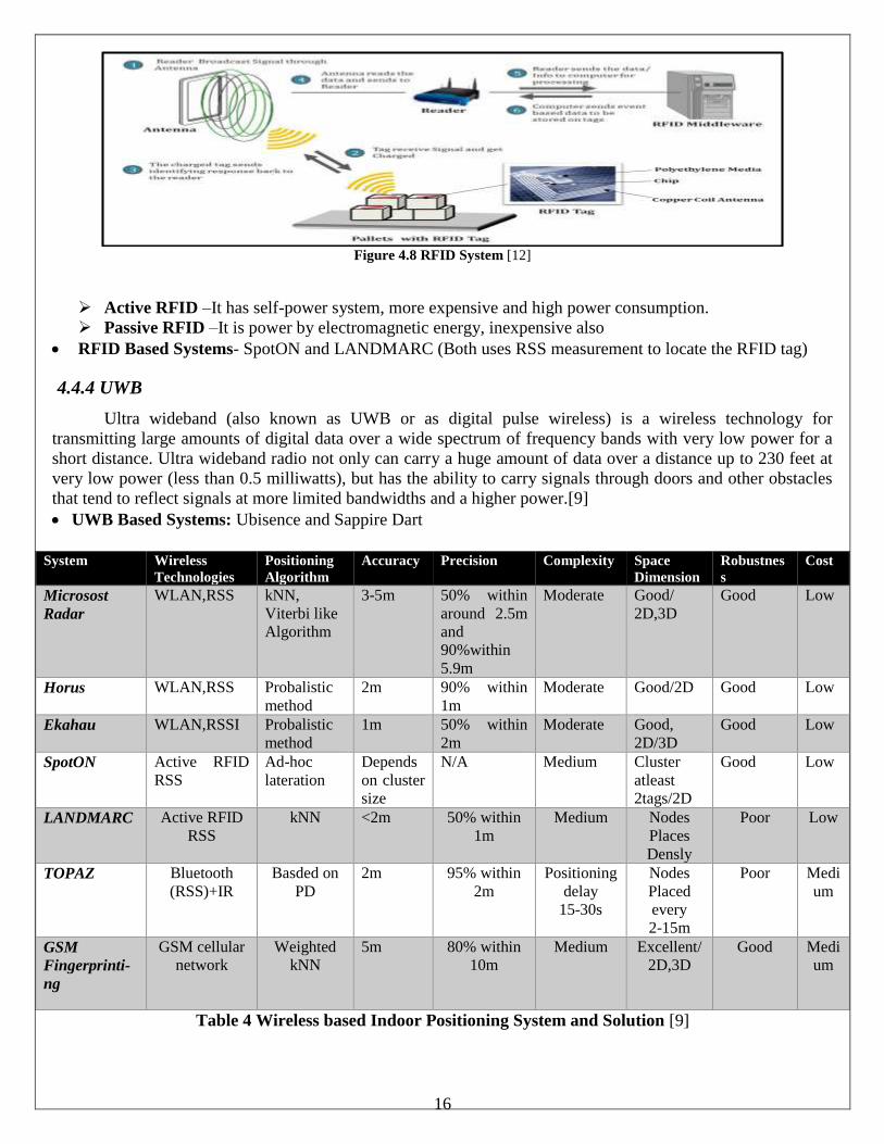
4.4.3 RFID
A RFID system is made up of two parts: a tag or label and a reader. RFID tags or labels are embedded
with a transmitter and a receiver. The RFID component on the tags have two parts: a microchip that stores and
processes information, and an antenna to receive and transmit a signal. The tag contains the specific serial
number for one specific object. [12]
To read the information encoded on a tag, a two-way radio transmitter-receiver called an interrogator or
reader emits a signal to the tag using an antenna. The tag responds with the information written in its memory
bank. The interrogator will then transmit the read results to an RFID computer program.
16
Figure 4.8 RFID System [12]
Active RFID –It has self-power system, more expensive and high power consumption.
Passive RFID –It is power by electromagnetic energy, inexpensive also
RFID Based Systems- SpotON and LANDMARC (Both uses RSS measurement to locate the RFID tag)
4.4.4 UWB
Ultra wideband (also known as UWB or as digital pulse wireless) is a wireless technology for
transmitting large amounts of digital data over a wide spectrum of frequency bands with very low power for a
short distance. Ultra wideband radio not only can carry a huge amount of data over a distance up to 230 feet at
very low power (less than 0.5 milliwatts), but has the ability to carry signals through doors and other obstacles
that tend to reflect signals at more limited bandwidths and a higher power.[9]
UWB Based Systems: Ubisence and Sappire Dart
Table 4 Wireless based Indoor Positioning System and Solution [9]
System Wireless
Technologies
Positioning
Algorithm
Accuracy Precision Complexity Space
Dimension
Robustnes
s
Cost
Microsost
Radar
WLAN,RSS kNN,
Viterbi like
Algorithm
3-5m 50% within
around 2.5m
and
90%within
5.9m
Moderate Good/
2D,3D
Good Low
Horus WLAN,RSS Probalistic
method
2m 90% within
1m
Moderate Good/2D Good Low
Ekahau WLAN,RSSI Probalistic
method
1m 50% within
2m
Moderate Good,
2D/3D
Good Low
SpotON Active RFID
RSS
Ad-hoc
lateration
Depends
on cluster
size
N/A Medium Cluster
atleast
2tags/2D
Good Low
LANDMARC Active RFID
RSS
kNN <2m 50% within
1m
Medium Nodes
Places
Densly
Poor Low
TOPAZ Bluetooth
(RSS)+IR
Basded on
PD
2m 95% within
2m
Positioning
delay
15-30s
Nodes
Placed
every
2-15m
Poor Medi
um
GSM
Fingerprinti-
ng
GSM cellular
network
Weighted
kNN
5m 80% within
10m
Medium Excellent/
2D,3D
Good Medi
um
17
Figure 5.1 System Architecture: Enhanced Location Based
Services [14]
Chapter 5 - GEOLOCATION TECHNOLOGIES
5.1 iOS Geolocation
5.1.1 Introduction
Apple is continuously trying to improve its iPhone geo-location technology. The geo-location
techniques used by apple are Wi-Fi based, GPS AGPS, Compass and Network based. [13] In GPS is used
satellite navigation. For AGPS, it is the improved version of GPS. In Wi-Fi it used MAC addressing and in
network based it used the base station ID. The compass is used for the direction of the client.
The system used here is the MAC OSx. The language used for coding is C, C++ and the database is apple.
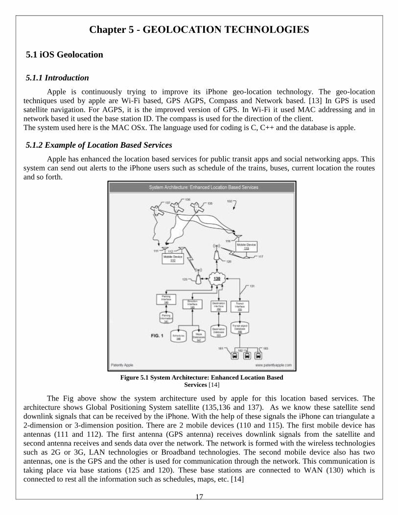
5.1.2 Example of Location Based Services
Apple has enhanced the location based services for public transit apps and social networking apps. This
system can send out alerts to the iPhone users such as schedule of the trains, buses, current location the routes
and so forth.
The Fig above show the system architecture used by apple for this location based services. The
architecture shows Global Positioning System satellite (135,136 and 137). As we know these satellite send
downlink signals that can be received by the iPhone. With the help of these signals the iPhone can triangulate a
2-dimension or 3-dimension position. There are 2 mobile devices (110 and 115). The first mobile device has
antennas (111 and 112). The first antenna (GPS antenna) receives downlink signals from the satellite and
second antenna receives and sends data over the network. The network is formed with the wireless technologies
such as 2G or 3G, LAN technologies or Broadband technologies. The second mobile device also has two
antennas, one is the GPS and the other is used for communication through the network. This communication is
taking place via base stations (125 and 120). These base stations are connected to WAN (130) which is
connected to rest all the information such as schedules, maps, etc. [14]
18
Figure 5.2 Android API
5.1.3 Privacy Setting
Apple also provides privacy for the users who are not willing to share their location. Location Services
uses GPS, Bluetooth, and crowd-sourced Wi-Fi hotspot and cell tower locations to determine the user’s
approximate location. Apple gives the option of turning off the location services by going in the settings option
or users can grant permission to access their location for each app that uses the location service. [15]
5.2 Android Geolocation
5.2.1 Introduction
The geo-location methods used by android are same as apple i.e. Wi-Fi based, GPS AGPS, Compass and
Network based. In GPS is used satellite navigation. For AGPS, it is the improved version of GPS. In Wi-Fi it
used MAC addressing and in network based it used the base station ID. The compass is used for the direction of
the client.
The system used here is the Linux. The language used for coding is C, C++ and Java. The database is Google.
The android phone incorporates two devices for geo-location. First, the GPS APIs which provide latitude and
longitude coordinates. Second, the magnetometer/compass can be used to provide direction relative to the earth
magnetic poles through an API.
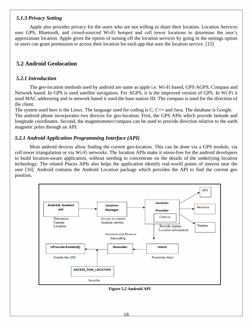
5.2.1 Android Application Programming Interface (API)
Most android devices allow finding the current geo-location. This can be done via a GPS module, via
cell tower triangulation or via Wi-Fi networks. The location APIs make it stress-free for the android developers
to build location-aware application, without needing to concentrate on the details of the underlying location
technology. The related Places APIs also helps the application identify real-world points of interest near the
user [16]. Android contains the Android Location package which provides the API to find the current geo
position.
19
A brief description of how the above entities work to determine the location is provided below:
● Location Manager: The location manager class provides access to the Android location service. This
service allows to access location providers, to resister location update.
● Location Provider: The location provider class is the superclass of the different location provider which
delivers the information about the current location. Android device have many location Provider but in
most cases the following location provider available:
● GPS: Use the GPS receiver in the android device to find the best location via satellites.
● Network: Uses the mobile network or Wi-Fi network to find the best location.
● Passive: Allows participating in location of updates of other components to save energy.
● Intent: User can also register an Intent which allows defining a proximity alert; this alert will be
triggered if the device enters an area given by a latitude, longitude and radius.
● Geo-coder: The Geo-coder class find the geo-coordinates for a given address and possible address for
given geo-coordinates. This process is known as forward and reverse geocoding.
● Security: If user wants to access the GPS sensor, user needs the ACCESS_FINE_LOCATION
permission.
● Prompt the user to Enabled GPS: - The user can decide if the GPS is enabled or not. User can find if a
Location Manager is enabled via the is ProviderEnabled() method.[17]
5.3 GLONASS System
GLONASS (Global Navigation Satellite System) is a space-based satellite navigation system operated
by the Russian Aerospace Defense Forces. It can be an alternative to GPS. It provides real time position and
velocity determination. GLONASS has 29 satellite constellations in total, but only 24 are operational covering
the earth. The Russian Government is really trying very hard to commercialize GLONASS project by offering
various GLONASS based navigation devices. The functioning of GLONASS is similar to GPS but may be not
as accurate as the GPS. If these two systems work to gather then a more accurate location can be given to the
user. [18]
5.4 How Can GLONASS and GPS Work Together?
If GLONASS and GPS both are accessed together then a device access about 55 Satellite constellations.
Hence this will result in enhance location accuracy, reliability and speed. It will also help the users to get
location at places where satellites of one system might not be available or blocked due to some reason. Now
days, the manufacturing companies are considering devices with antennas for both the navigation systems. This
combination has been referred to as a Dual Core location based service.
20
Chapter 6 - CONCLUSION
Geolocation has always been and is clearly going to continue to be a big part of our day-to-day lives
going forward. It helps bring the knowledge of geographical position to improve the real, everyday things we
need to do. With location-enhanced searches on smart phones, mobile PCs and tablets, we can just do them
faster and smarter. And with the roll out of the 4G LTE technology which has been nothing less than ground
breaking and the data processing speeds that it offers, the possibilities are limitless for wireless geolocation
applications.
This report aims to be a quick study of the process of geo-location and the main geo-location
technologies namely, E-CID, AGNSS and TDOA, available for the LTE system. It provides a brief overview of
the LTE architecture for better understanding of the positioning process that was covered in the chapter that
followed. While, traditional satellite and network-element based geo-positioning is highly feasible for the great
outdoors, because of the path-loss that is experienced indoors, these systems cannot work properly and require
modifications. The call for explicit indoor geolocation methodologies because of the amount of time that is
spent indoors by the people of today, has sparked extensive research into the field of indoor geolocation
techniques and systems, which this paper explores and summarizes. But, geolocation does not exist as an
independent entity. This location information serves a higher purpose in the form of the applications and
services it is used for. Be it social, commercial, medical or military applications. The report also shows the
technologies used by android and apple to find any specific locations. A small idea about GLONASS is also
explained in the report.
When geo-location features first emerged for non-military use, it was mainly used for way-finding or
terrain mapping applications such as mobile maps. But, we have come a long way since then with geolocation
now being used in just about every field. In the medical field geolocation has found to be very useful for
locating patients and expensive equipment. Thus, saving time and lives. And the use of geolocation for military
purposes was how it all began, as we know. Despite initial reservations, it has also found a firm foothold in our
social lives and is being used to enhance user experience in every possible way. It is safe to say that with the
constantly evolving technology and wireless standards, geolocation technologies will continue to develop to
keep pace and provide many more applications.
21
References
[1] http://en.wikipedia.org/wiki/Geolocation
[2] www.floatlearning.com
[3] http://floatlearning.com/?s=geo+location
[4] Alcatel Lucent. “The LTE Network Architecture; A comprehensive tutorial.” Strategic White Paper (2009)
[5] Innovations, Telesystem. "LTE in a Nutshell." White Paper (2010).
[6] Freescale Semiconductor, Inc. “Long Term Evolution Protocol Overview.” White Paper (2008)
[7] Rohde & Schwarz GmbH & Co. KG “LTE Location Based Services Technology Introduction.” White Paper
(2013)
[8] Spirent. “An Overview of LTE Positioning.” White Paper (2012)
[9] Hui, L., et al., Survey of Wireless Indoor Positioning Techniques and Systems. Systems, Man, and
Cybernetics, Part C: Applications and Reviews, IEEE Transactions on, 2007. 37(6): p. 1067-1080.
[10] Kaveh Pahlavan, Xinrong Li, Mika Ylianttila, Ranvir Chana, Matti Latva-aho, An Overview of Wireless
Indoor Geolocation Techniques and Systems, Lecture Notes in Computer Science Volume 1818, 2000, pp 1-13
[11] http://www.locata.com/technology/locata-tech-explained/
[12] http://www.epc-rfid.info/rfid
[13] https://www.apple.com/business/docs/iOS_Security_Guide.pdf
[14]http://www.patentlyapple.com/patently-apple/2010/01/apple-iphone-to-gain-social-networking-public-
transit-apps.html
[15] https://support.apple.com/en-us/HT203033
[16] https://developer.android.com/google/play-services/location.html
[17] http://www.vogella.com/tutorials/AndroidLocationAPI/article.html
[18] http://en.wikipedia.org/wiki/GLONASS
[19] http://www.tutorialspoint.com/lte/
[20] www.masterltefaster.com