Embed Size (px)
Citation preview

WIRELESS 11N LONG RANGE OUTDOOR AP / CBENS500EXT User GuideV1.0

TABLE OF CONTENTS
NTS
0-vi0-viii
1-1
1-2
. . . . . . . . . . . . . . . . . . . . . . . .1-2
. . . . . . . . . . . . . . . . . . . . . . . .1-2
. . . . . . . . . . . . . . . . . . . . . . . .1-3
. . . . . . . . . . . . . . . . . . . . . . . .1-4
. . . . . . . . . . . . . . . . . . . . . . . .1-4
. . . . . . . . . . . . . . . . . . . . . . . .1-4
. . . . . . . . . . . . . . . . . . . . . . . .1-4
. . . . . . . . . . . . . . . . . . . . . . . .1-5
1-6
I
TABLE OF CONTE
ConventionsCopyright
Product Overview
Package Contents
Product Overview
Hardware Features . . . . . . . . . . . . . . . . . . . . . . . . . . .
Software Features . . . . . . . . . . . . . . . . . . . . . . . . . . . .
Benefits . . . . . . . . . . . . . . . . . . . . . . . . . . . . . . . . . . .
Technical Specification . . . . . . . . . . . . . . . . . . . . . . . . .
Hardware Specification . . . . . . . . . . . . . . . . . . . . . . .
Software Specification. . . . . . . . . . . . . . . . . . . . . . . .
Environment & Mechanical. . . . . . . . . . . . . . . . . . . . .
Wireless Specification . . . . . . . . . . . . . . . . . . . . . . . .
Product Layout
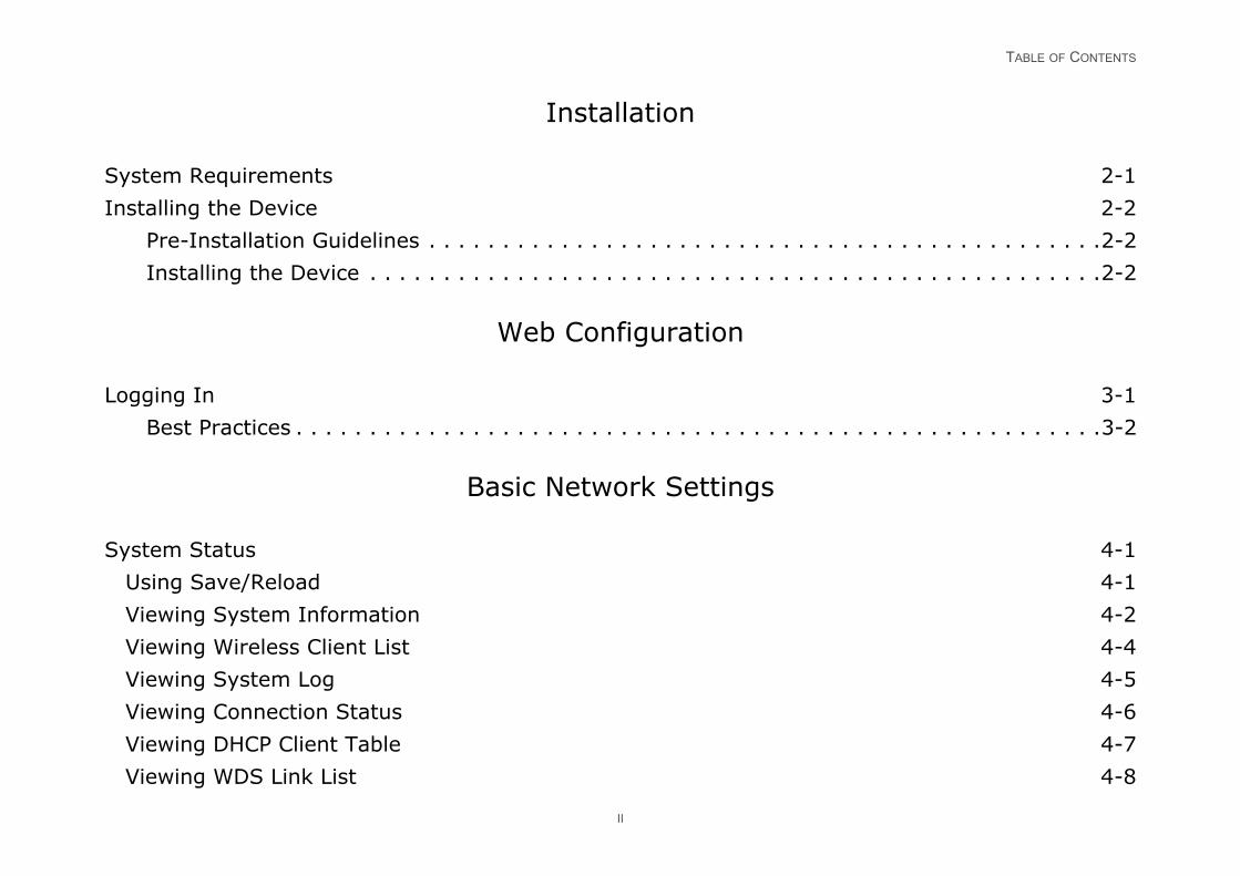
TABLE OF CONTENTS
2-1
2-2
. . . . . . . . . . . . . . . . . . . .2-2
. . . . . . . . . . . . . . . . . . . .2-2
3-1
. . . . . . . . . . . . . . . . . . . .3-2
4-1
4-1
4-2
4-4
4-5
4-6
4-7
4-8
II
Installation
System Requirements
Installing the Device
Pre-Installation Guidelines . . . . . . . . . . . . . . . . . . . . . . . . . .
Installing the Device . . . . . . . . . . . . . . . . . . . . . . . . . . . . . .
Web Configuration
Logging In
Best Practices . . . . . . . . . . . . . . . . . . . . . . . . . . . . . . . . . . .
Basic Network Settings
System Status
Using Save/Reload
Viewing System Information
Viewing Wireless Client List
Viewing System Log
Viewing Connection Status
Viewing DHCP Client Table
Viewing WDS Link List
TABLE OF CONTENTS
4-9
4-9
4-10
4-11
4-12
4-12
. . . . . . . . . . . . . . . . . . . .4-12
. . . . . . . . . . . . . . . . . . . .4-13
. . . . . . . . . . . . . . . . . . . .4-14
. . . . . . . . . . . . . . . . . . . .4-15
4-17
4-18
4-19
4-21
4-22
4-22
. . . . . . . . . . . . . . . . . . . .4-22
. . . . . . . . . . . . . . . . . . . .4-24
. . . . . . . . . . . . . . . . . . . .4-25
. . . . . . . . . . . . . . . . . . . .4-27
III
System Setup
Configuring Operation Mode
Configuring IP Settings
Configuring Spanning Tree Settings
Router Setup
Configuring WAN Settings
Static IP. . . . . . . . . . . . . . . . . . . . . . . . . . . . . . . . . . . . . .
Dynamic IP. . . . . . . . . . . . . . . . . . . . . . . . . . . . . . . . . . . .
Point-to-Point Protocol over Ethernet (PPPoE). . . . . . . . . . . .
Point-to-Point Tunnelling Protocol (PPTP) . . . . . . . . . . . . . . .
Configuring LAN Settings
Configuring VPN Pass-Through
Configuring Port Forwarding
Configuring Demilitarized Zone
Configuring Wireless LAN
Configuring Wireless Settings
Access Point Mode. . . . . . . . . . . . . . . . . . . . . . . . . . . . . . .
Client Bridge Mode . . . . . . . . . . . . . . . . . . . . . . . . . . . . . .
WDS Bridge Mode . . . . . . . . . . . . . . . . . . . . . . . . . . . . . . .
Client Router Mode . . . . . . . . . . . . . . . . . . . . . . . . . . . . . .
TABLE OF CONTENTS
4-28
. . . . . . . . . . . . . . . . . . .4-28
. . . . . . . . . . . . . . . . . . .4-29
. . . . . . . . . . . . . . . . . . .4-30
. . . . . . . . . . . . . . . . . . .4-31
. . . . . . . . . . . . . . . . . . .4-32
. . . . . . . . . . . . . . . . . . .4-33
. . . . . . . . . . . . . . . . . . .4-34
4-35
4-36
4-37
. . . . . . . . . . . . . . . . . . .4-37
. . . . . . . . . . . . . . . . . . .4-38
4-39
4-39
4-40
4-41
4-43
4-44
4-45
4-46
IV
Configuring Wireless Security
Wired Equivalent Privacy (WEP) . . . . . . . . . . . . . . . . . . . . . .
Wi-Fi Protected Access Pre-Shared Key (WPA-PSK) . . . . . . . . .
Wi-Fi Protected Access 2 Pre-Shared Key (WPA2-PSK). . . . . . .
Wi-Fi Protected Access Pre-Shared Key (WPA-PSK) Mixed . . . .
Wi-Fi Protected Access (WPA) . . . . . . . . . . . . . . . . . . . . . . . .
Wi-Fi Protected Access 2 (WPA2) . . . . . . . . . . . . . . . . . . . . .
Wi-Fi Protected Access (WPA) Mixed . . . . . . . . . . . . . . . . . . .
Configuring Wireless MAC Filter
Configuring WDS Link Settings
Configuring Wireless Advanced Settings
Wireless Traffic Shaping. . . . . . . . . . . . . . . . . . . . . . . . . . . .
Client Limit. . . . . . . . . . . . . . . . . . . . . . . . . . . . . . . . . . . . .
Management Setup
Configuring Administrator Account
Configuring Management VLAN
Configuring SNMP
Configuring Backup/Restore Settings
Configuring Auto Reboot Settings
Configuring Firmware Upgrade
Configuring System Time
TABLE OF CONTENTS
4-47
. . . . . . . . . . . . . . . . . . . .4-47
. . . . . . . . . . . . . . . . . . . .4-48
4-49
4-50
4-51
4-52
4-53
4-54
A-1
B-1
C-1
V
Configuring Wi-Fi Schedule
Add a Schedule Service . . . . . . . . . . . . . . . . . . . . . . . . . . .
Schedule Services Table. . . . . . . . . . . . . . . . . . . . . . . . . . .
Configuring Command Line Interface
Configuring Logging
Configuring Diagnostics
Viewing Device Discovery
Configure Denial of Service Protection
Logging Out
Appendix A
Federal Communication Commission Interference Statement
Appendix B
Industry Canada Statement
Appendix C
WorldWide Technical Support
CONVENTIONS
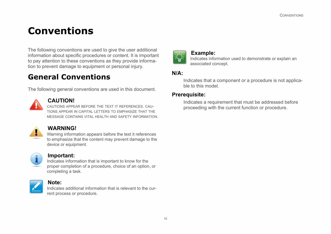
t a component or a procedure is not applica-del.
quirement that must be addressed before ith the current function or procedure.
e:nformation used to demonstrate or explain an concept.
VI
Conventions
The following conventions are used to give the user additional information about specific procedures or content. It is important to pay attention to these conventions as they provide informa-tion to prevent damage to equipment or personal injury.
General Conventions
The following general conventions are used in this document.
N/A:Indicates thable to this mo
Prerequisite:Indicates a reproceeding w
CAUTION!CAUTIONS APPEAR BEFORE THE TEXT IT REFERENCES. CAU-TIONS APPEAR IN CAPITAL LETTERS TO EMPHASIZE THAT THE MESSAGE CONTAINS VITAL HEALTH AND SAFETY INFORMATION.
WARNING!Warning information appears before the text it references to emphasize that the content may prevent damage to the device or equipment.
Important:Indicates information that is important to know for the proper completion of a procedure, choice of an option, or completing a task.
Note:Indicates additional information that is relevant to the cur-rent process or procedure.
!
!
ExamplIndicates iassociated

CONVENTIONS
VII
Typographical Conventions
The following typographical conventions are used in this docu-ment:
Italics
Indicates book titles, directory names, file names, path names, and program/process names.
Constant width
Indicates computer output shown on a computer screen, includ-ing menus, prompts, responses to input, and error messages.
Constant width bold
Indicates commands lines as entered on the computer. Vari-ables contained within user input are shown in angle brackets (< >).
Bold
Indicates keyboard keys that are pressed by the user.

COPYRIGHT
VIII
Copyright
This user guide and its content is copyright of © EnGenius Net-works, 2012. All rights reserved.
Any redistribution or reproduction in part or in whole in any form is prohibited.
Do not distribute, transmit, store in any form of electronic retrieval system or commercially exploit the content without the expressed written permission of EnGenius Networks.

Product Overview
Chapter 1

PRODUCT OVERVIEW PACKAGE CONTENTS
1-1
1.1 Package Contents
ENS500EXT
Quick Start Guide
Technical Support Card
Pole Mounting Strap x2
Wall Mounting Screw Set
PoE Injector (EPE-1212) with Power Adapter
Two detachable 5 dBi high gain omni-directional antennas
PRODUCT OVERVIEW PRODUCT OVERVIEW
dicators have the best transmit and receive ic communication
: Support proprietary 24V passive power
eatures
: 4 SSID supported. Each SSID can set or WAN access setting
t-to-Point Protocol over Ethernet at Client This function will keep trying when failed or
to-Point Tunneling Protocol (PPTP) is a plementing virtual private networks
hrough: Support VLAN Pass-through
grade: Upgrading firmware via web ng are reserved after upgrade
kup: Reset to factory default. User can ing into a file via WEB
Route: Built-in PING function & Trace n in Web GUI
IB II(RFC1213), Private MIB
2c, V3
1-2
1.2 Product Overview
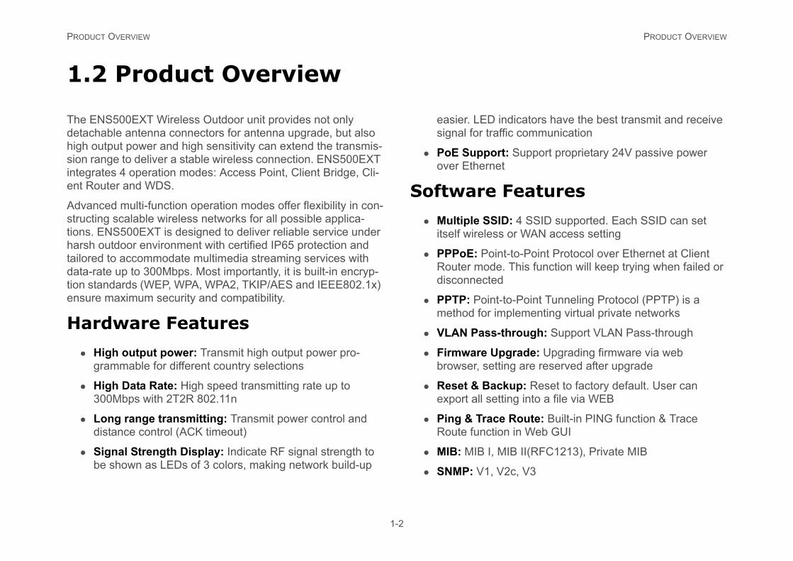
The ENS500EXT Wireless Outdoor unit provides not only detachable antenna connectors for antenna upgrade, but also high output power and high sensitivity can extend the transmis-sion range to deliver a stable wireless connection. ENS500EXT integrates 4 operation modes: Access Point, Client Bridge, Cli-ent Router and WDS.
Advanced multi-function operation modes offer flexibility in con-structing scalable wireless networks for all possible applica-tions. ENS500EXT is designed to deliver reliable service under harsh outdoor environment with certified IP65 protection and tailored to accommodate multimedia streaming services with data-rate up to 300Mbps. Most importantly, it is built-in encryp-tion standards (WEP, WPA, WPA2, TKIP/AES and IEEE802.1x) ensure maximum security and compatibility.
Hardware Features
High output power: Transmit high output power pro-grammable for different country selections
High Data Rate: High speed transmitting rate up to 300Mbps with 2T2R 802.11n
Long range transmitting: Transmit power control and distance control (ACK timeout)
Signal Strength Display: Indicate RF signal strength to be shown as LEDs of 3 colors, making network build-up
easier. LED insignal for traff
PoE Supportover Ethernet
Software F
Multiple SSIDitself wireless
PPPoE: PoinRouter mode.disconnected
PPTP: Point-method for im
VLAN Pass-t
Firmware Upbrowser, setti
Reset & Bacexport all sett
Ping & TraceRoute functio
MIB: MIB I, M
SNMP: V1, V
PRODUCT OVERVIEW BENEFITS
nsions to Ethernet networks
work managers in dynamic environments to caused by moves, extensions to networks, .
ckup
can implement WLANs to provide backup applications running on wired networks.
in training/educational
rporations and students at universities are a re wireless connectivity can be used to facili-mation, information exchanges, and learn-
1-3
Benefits
The ENS500EXT is the ideal product around which you can build your WLAN. The following list summarizes a few key advantages that WLANs have over wired networks:
Ideal for hard-to-wire environments
There are many scenarios where cables cannot be used to con-nect networking devices. Historic and older buildings, open areas, and busy streets, for example, make wired LAN installa-tions difficult, expensive, or impossible.
Temporary workgroups
WLANs make it easy to provide connectivity to temporary work-groups that will later be removed. Examples include parks, ath-letic arenas, exhibition centers, disaster-recovery shelters, temporary offices, and construction sites.
Ability to access real-time information
With a WLAN, workers who rely on access to real-time informa-tion, such as doctors and nurses, point-of-sale employees, mobile workers, and warehouse personnel, can access the data they need and increase productivity, without having to look for a place to plug into the network.
Frequently changed environments
WLANs are well suited for showrooms, meeting rooms, retail stores, and manufacturing sites where workplaces are rear-ranged frequently.
Wireless exte
WLANs enable netminimize overheadand other changes
Wired LAN ba
Network managersfor mission-critical
Mobility withfacilities
Training sites at cofew examples whetate access to inforing.
PRODUCT OVERVIEW TECHNICAL SPECIFICATION
WDS Bridge / WDS Station
upported
ccounting
/ VLAN Pass-through
ot
uling
ption-64/128/152 bit
2 Personal (WPA-PSK using TKIP or AES)
2 Enterprise (WPA-EAP using TKIP)
in beacons
ss filtering, up to 50 field
TA (Client) connected list
t & Mechanical
Range:
-20°C~70°C
0°C to 80°C
n-condensing): 0%~90% typical
1-4
Technical Specification
Hardware Specification
Physical Interface:
2 x RJ-45 for 10/100 Fast Ethernet; one port is compat-ible with PoE
1 x Reset Button
Power Requirements:
Active Ethernet (Power over Ethernet)
Proprietary PoE design
Power Adapter 24V / 0.6A
Software Specification
Operation Mode: Client Bridge, Access Point, Client Router, WDS AP, WDS Bridge, WDS Station
Wireless/Network:
Auto Channel Selection (Setting varies by Regular Domains)
Obey Regulatory Power
Distance Control (802.1x ACK (acknowledgement) timeout)
CLI Supported
802.1x Supplicant (CB Mode)
4 SSIDs
WDS AP /
Multicast S
RADIUS A
VLAN Tag
Auto Rebo
WiFi Sched
Security:
WEP Encry
WPA/WPA
WPA/WPA
Hide SSID
MAC addre
Wireless S
QoS: WMM
Environmen
Temperature
Operating
Storage -3
Humidity (no
Dimensions
PRODUCT OVERVIEW TECHNICAL SPECIFICATION
ecification
and: 802.11a/n
0 Mbps
Detachable SMA Connector
imum power of the radio frequency band may nt depending on local regulations.
1-5
with antenna: 100mm (4”) x 37.5mm (1.375””) x 205mm (8”) (W x D x H)
without antenna: 100mm (4”) x 37.5mm (1.37”) x 189mm (7.375”) (W x D x H)
Weight
with antenna: 242g (0.11 lbs) ± 2g
without antenna: 275g (0.125lbs) ±2g
Wireless Sp
Frequency B
Data rate: 30
Antenna: 2 x
Note:The maxbe differe
PRODUCT OVERVIEW PRODUCT LAYOUT
DESCRIPTION
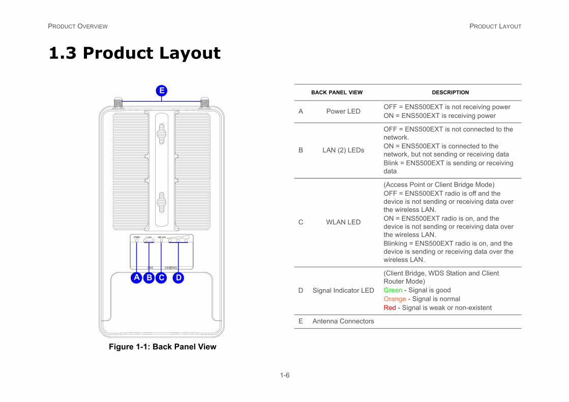
OFF = ENS500EXT is not receiving powerON = ENS500EXT is receiving power
s
OFF = ENS500EXT is not connected to the network.ON = ENS500EXT is connected to the network, but not sending or receiving dataBlink = ENS500EXT is sending or receiving data
(Access Point or Client Bridge Mode)OFF = ENS500EXT radio is off and the device is not sending or receiving data over the wireless LAN.ON = ENS500EXT radio is on, and the device is not sending or receiving data over the wireless LAN.Blinking = ENS500EXT radio is on, and the device is sending or receiving data over the wireless LAN.
LED
(Client Bridge, WDS Station and Client Router Mode)Green - Signal is goodOrange - Signal is normalRed - Signal is weak or non-existent
tors
1-6
1.3 Product Layout
Figure 1-1: Back Panel View
A B C D
E BACK PANEL VIEW
A Power LED
B LAN (2) LED
C WLAN LED
D Signal Indicator
E Antenna Connec
PRODUCT OVERVIEW PRODUCT LAYOUT
1-7
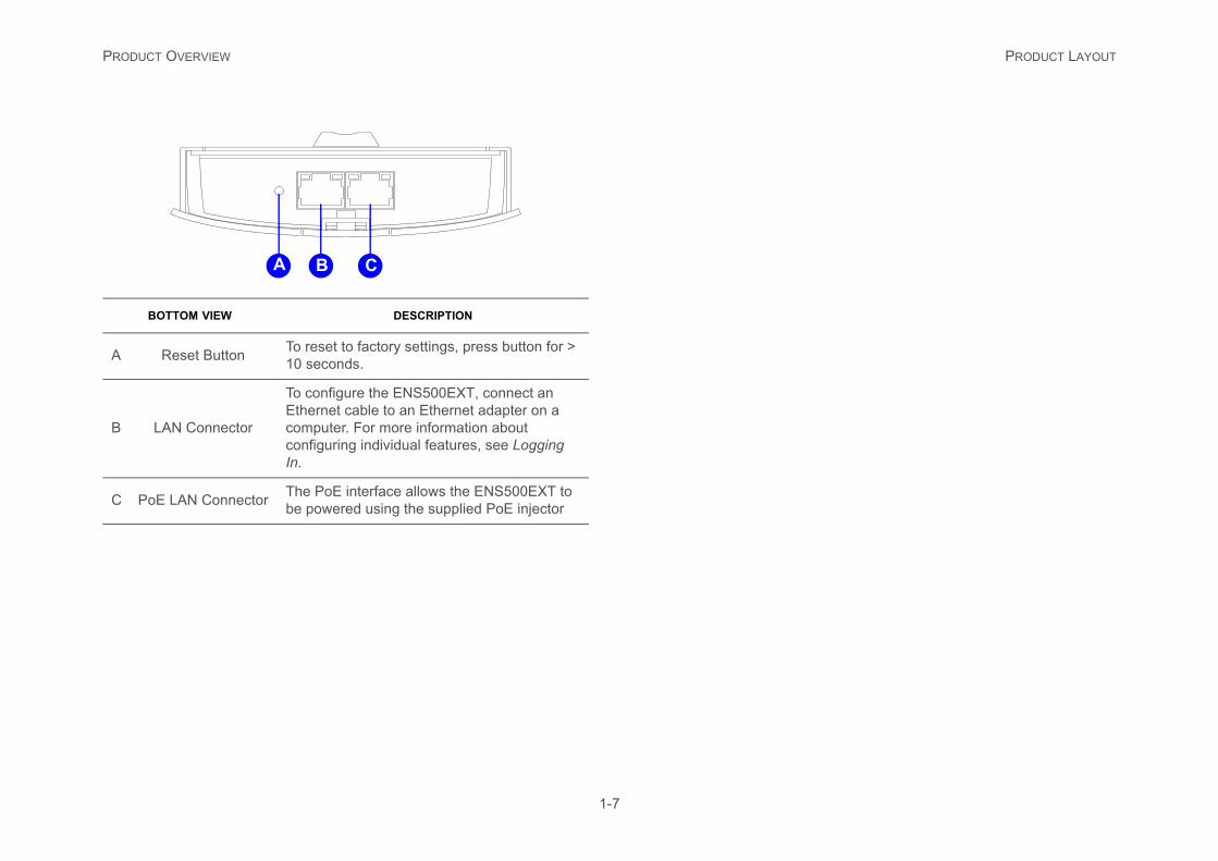
BOTTOM VIEW DESCRIPTION
A Reset Button To reset to factory settings, press button for > 10 seconds.
B LAN Connector
To configure the ENS500EXT, connect an Ethernet cable to an Ethernet adapter on a computer. For more information about configuring individual features, see Logging In.
C PoE LAN Connector The PoE interface allows the ENS500EXT to be powered using the supplied PoE injector
A B C

Installation
Chapter 2
INSTALLATION SYSTEM REQUIREMENTS
2-1
2.1 System Requirements
To install the ENS500EXT, you need the following:
Computer (Windows, Linux, Mac OS X Operating System)
Web Browser (Internet Explorer, FireFox, Chrome, Safari)
Network Interface equipped: (one of the following)
Wired connectivity: Network Interface with an open RJ-45 Ethernet Port
Wireless Connectivity:
Embedded 802.11n Wi-Fi wireless networking, IEEE 802.11a/n compatible
Wi-Fi Card, USB Wi-Fi Dongle (802.11 a/n)
An existing router or access point (AP) with SSID broad-cast
1x CAT5e Ethernet Cable
INSTALLATION INSTALLING THE DEVICE
the Device
00EXT, use the following procedure to n a pole and refer to the figure below.
bottom cover protecting the RJ-45 connec-
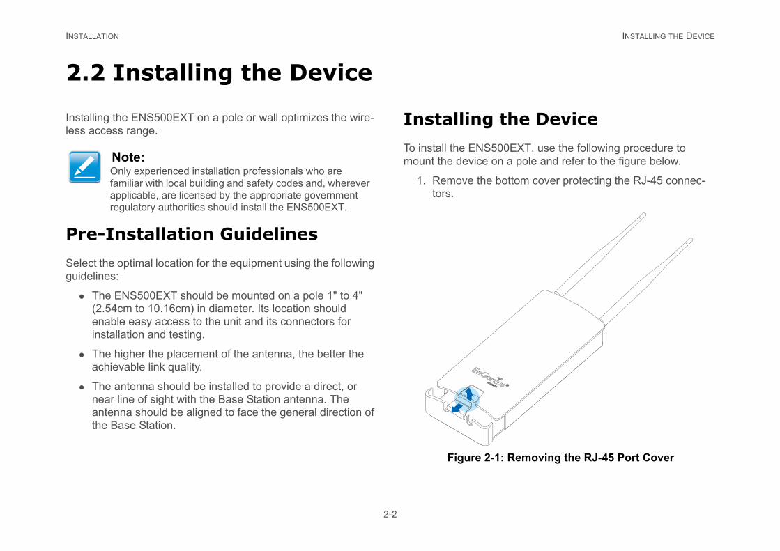
1: Removing the RJ-45 Port Cover
2-2
2.2 Installing the Device
Installing the ENS500EXT on a pole or wall optimizes the wire-less access range.
Pre-Installation Guidelines
Select the optimal location for the equipment using the following guidelines:
The ENS500EXT should be mounted on a pole 1" to 4" (2.54cm to 10.16cm) in diameter. Its location should enable easy access to the unit and its connectors for installation and testing.
The higher the placement of the antenna, the better the achievable link quality.
The antenna should be installed to provide a direct, or near line of sight with the Base Station antenna. The antenna should be aligned to face the general direction of the Base Station.
Installing
To install the ENS5mount the device o
1. Remove the tors.
Figure 2-
Note:Only experienced installation professionals who are familiar with local building and safety codes and, wherever applicable, are licensed by the appropriate government regulatory authorities should install the ENS500EXT.
INSTALLATION INSTALLING THE DEVICE
Ethernet cable into the LAN port of the PoE onnect the other end of Ethernet cable to
of the PC.
2-2: Installing the ENS500EXT
cure the two antennas to the top of the .
PoE
LAN
2-3
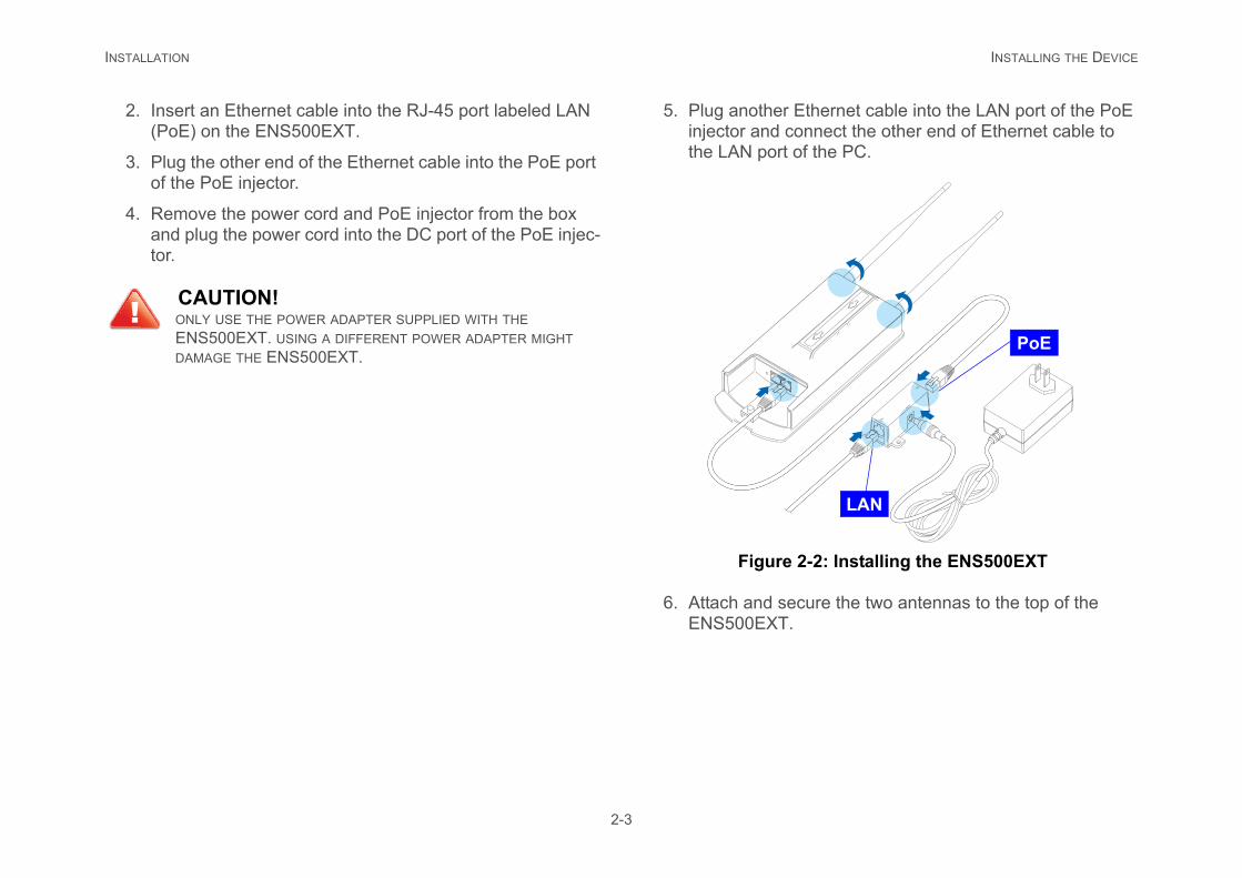
2. Insert an Ethernet cable into the RJ-45 port labeled LAN (PoE) on the ENS500EXT.
3. Plug the other end of the Ethernet cable into the PoE port of the PoE injector.
4. Remove the power cord and PoE injector from the box and plug the power cord into the DC port of the PoE injec-tor.
5. Plug anotherinjector and cthe LAN port
Figure
6. Attach and seENS500EXT
CAUTION!ONLY USE THE POWER ADAPTER SUPPLIED WITH THE ENS500EXT. USING A DIFFERENT POWER ADAPTER MIGHT DAMAGE THE ENS500EXT.
!
INSTALLATION INSTALLING THE DEVICE
dhesive label to a position on the wall where e to install the ENS500EXT.
-4: Screw Layout Adhesive Label
2-4
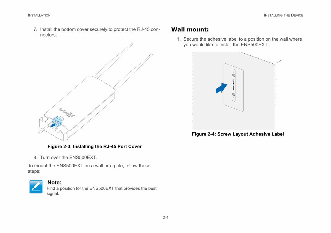
7. Install the bottom cover securely to protect the RJ-45 con-nectors.
Figure 2-3: Installing the RJ-45 Port Cover
8. Turn over the ENS500EXT.
To mount the ENS500EXT on a wall or a pole, follow these steps:
Wall mount:
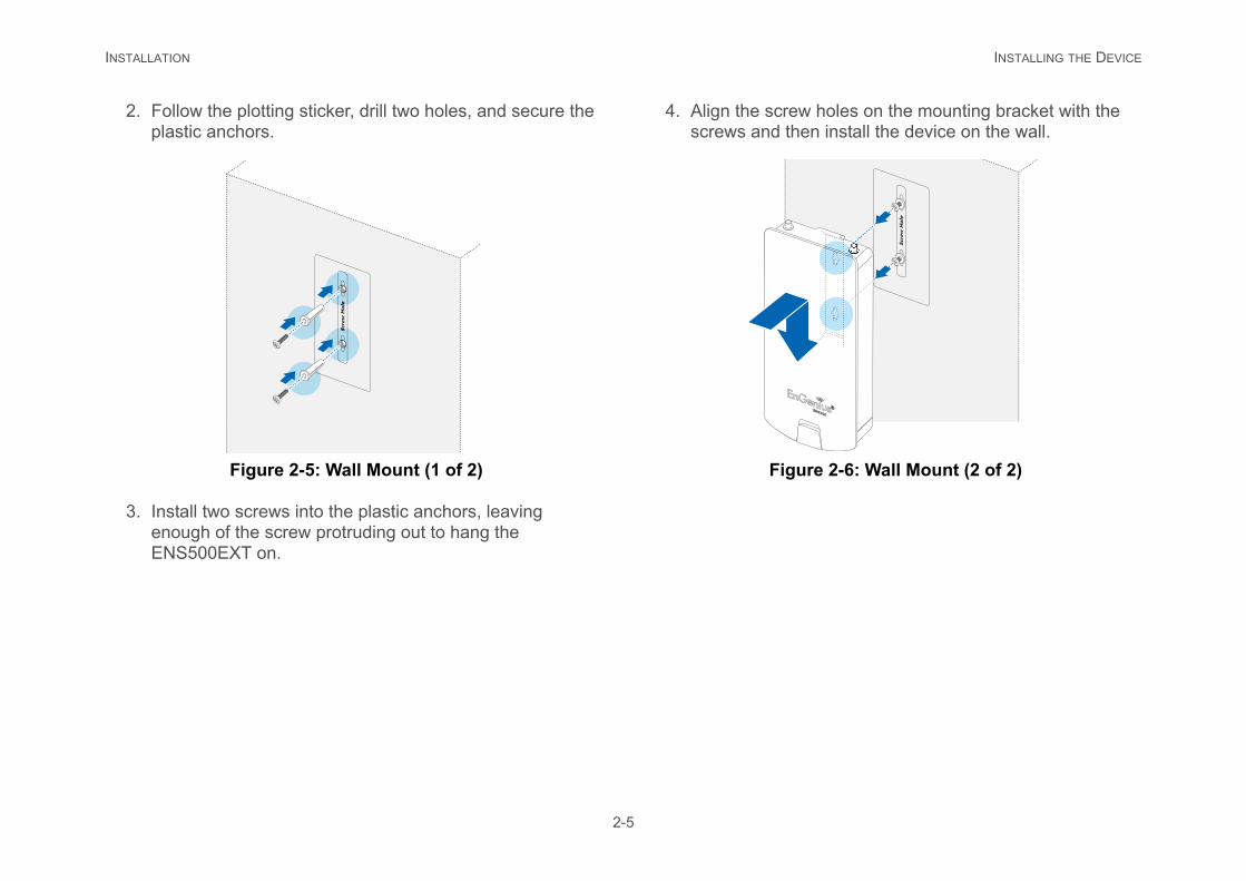
1. Secure the ayou would lik
Figure 2
Note:Find a position for the ENS500EXT that provides the best signal.
INSTALLATION INSTALLING THE DEVICE
w holes on the mounting bracket with the hen install the device on the wall.
ure 2-6: Wall Mount (2 of 2)
2-5
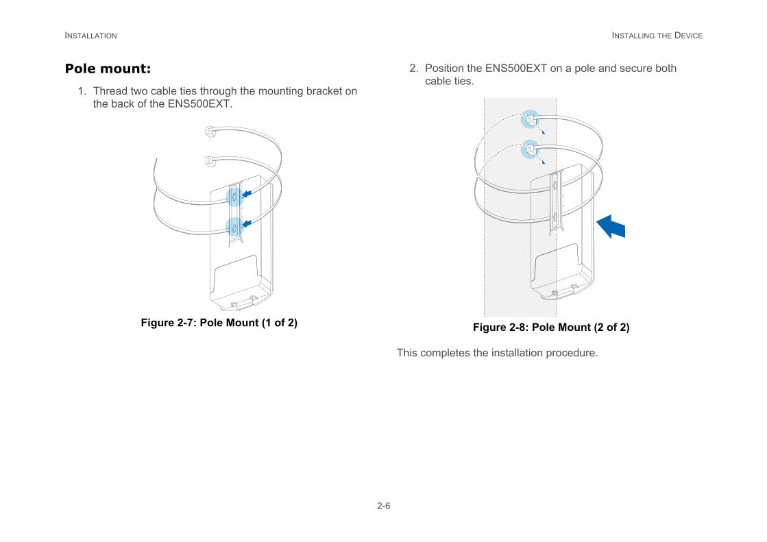
2. Follow the plotting sticker, drill two holes, and secure the plastic anchors.
Figure 2-5: Wall Mount (1 of 2)
3. Install two screws into the plastic anchors, leaving enough of the screw protruding out to hang the ENS500EXT on.
4. Align the screscrews and t
Fig
INSTALLATION INSTALLING THE DEVICE
NS500EXT on a pole and secure both
ure 2-8: Pole Mount (2 of 2)
installation procedure.
2-6
Pole mount:
1. Thread two cable ties through the mounting bracket on the back of the ENS500EXT.
Figure 2-7: Pole Mount (1 of 2)
2. Position the Ecable ties.
Fig
This completes the

Web Configuration
Chapter 3
WEB CONFIGURATION LOGGING IN
creen appears, enter admin for the user-ld and admin for the password in the bottom
2: Windows Security Login Dialog
ontinue or Reset to abort the login.
to use the instructions in the following chap-e ENS500EXT.
3-1
3.1 Logging In
The ENS500EXT has a built-in Web Configurator that lets you manage the unit from any location using a Web browser that supports HTTP and has Javascript installed.
After configuring the computer for TCP/IP using the procedure appropriate for your operating system, use that computer’s Web browser to log in to the ENS500EXT Web Configurator.
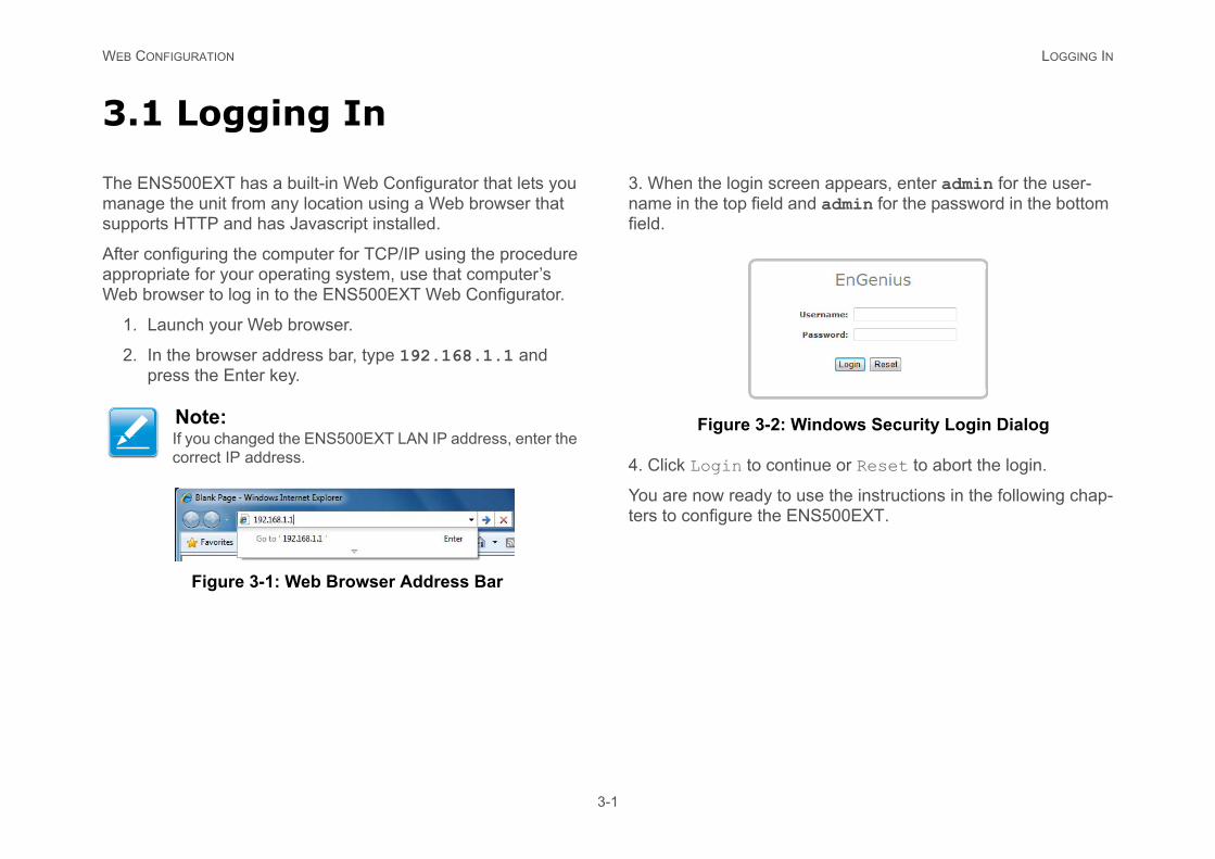
1. Launch your Web browser.
2. In the browser address bar, type 192.168.1.1 and press the Enter key.
Figure 3-1: Web Browser Address Bar
3. When the login sname in the top fiefield.
Figure 3-
4. Click Login to c
You are now readyters to configure th
Note:If you changed the ENS500EXT LAN IP address, enter the correct IP address.
WEB CONFIGURATION BEST PRACTICES
3-2
Best Practices
Perform the following procedures regularly to make the ENS500EXT more secure and manage the ENS500EXT more effectively.
Change the default password Use a password that is not easy to guess and that contains different characters, such as numbers and letters. The ENS500EXT username cannot be changed. For more information, see Configur-ing Administrator Account.
Back up the configuration and be sure you know how to restore it. Restoring an earlier working configuration can be useful if the ENS500EXT becomes unstable or crashes. If you forget your password, you will have to reset the ENS500EXT to its factory default settings and lose any customized override settings you configured. However, if you back up an earlier configuration, you will not have to completely reconfigure the ENS500EXT. You can simply restore your last configuration. For more infor-mation, see Configuring Backup/Restore Settings.
Basic Network Settings
Chapter 4
BASIC NETWORK SETTINGS SYSTEM STATUS
4-1
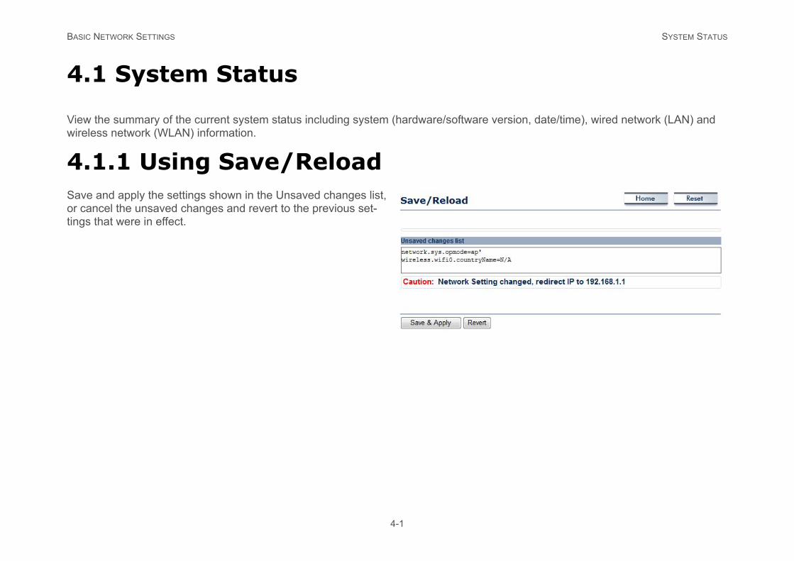
4.1 System Status
View the summary of the current system status including system (hardware/software version, date/time), wired network (LAN) and wireless network (WLAN) information.
4.1.1 Using Save/ReloadSave and apply the settings shown in the Unsaved changes list, or cancel the unsaved changes and revert to the previous set-tings that were in effect.
BASIC NETWORK SETTINGS VIEWING SYSTEM INFORMATION
4-2
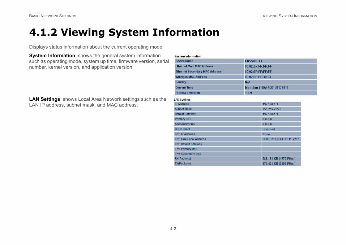
4.1.2 Viewing System InformationDisplays status information about the current operating mode.
System Information shows the general system information such as operating mode, system up time, firmware version, serial number, kernel version, and application version.
LAN Settings shows Local Area Network settings such as the LAN IP address, subnet mask, and MAC address.
BASIC NETWORK SETTINGS VIEWING SYSTEM INFORMATION
4-3
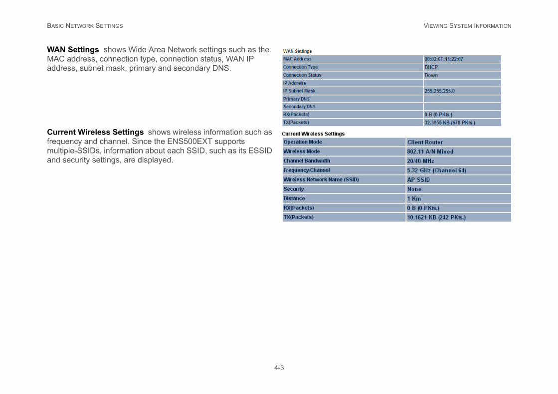
WAN Settings shows Wide Area Network settings such as the MAC address, connection type, connection status, WAN IP address, subnet mask, primary and secondary DNS.
Current Wireless Settings shows wireless information such as frequency and channel. Since the ENS500EXT supports multiple-SSIDs, information about each SSID, such as its ESSID and security settings, are displayed.
BASIC NETWORK SETTINGS VIEWING WIRELESS CLIENT LIST
4-4
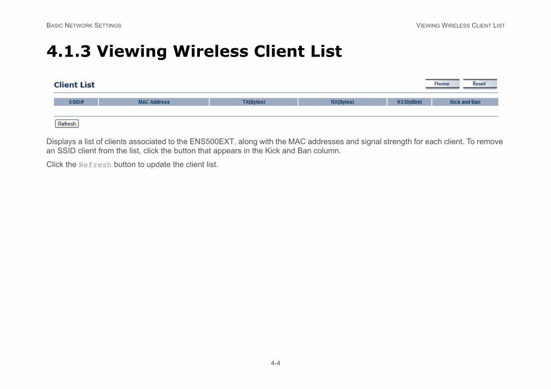
4.1.3 Viewing Wireless Client List
Displays a list of clients associated to the ENS500EXT, along with the MAC addresses and signal strength for each client. To remove an SSID client from the list, click the button that appears in the Kick and Ban column.
Click the Refresh button to update the client list.
BASIC NETWORK SETTINGS VIEWING SYSTEM LOG
4-5
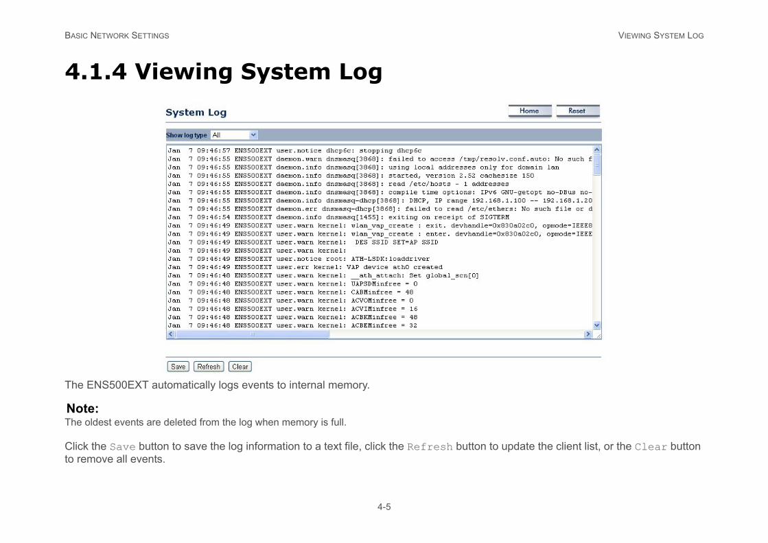
4.1.4 Viewing System Log
The ENS500EXT automatically logs events to internal memory.
Note:The oldest events are deleted from the log when memory is full.
Click the Save button to save the log information to a text file, click the Refresh button to update the client list, or the Clear button to remove all events.
BASIC NETWORK SETTINGS VIEWING CONNECTION STATUS
4-6
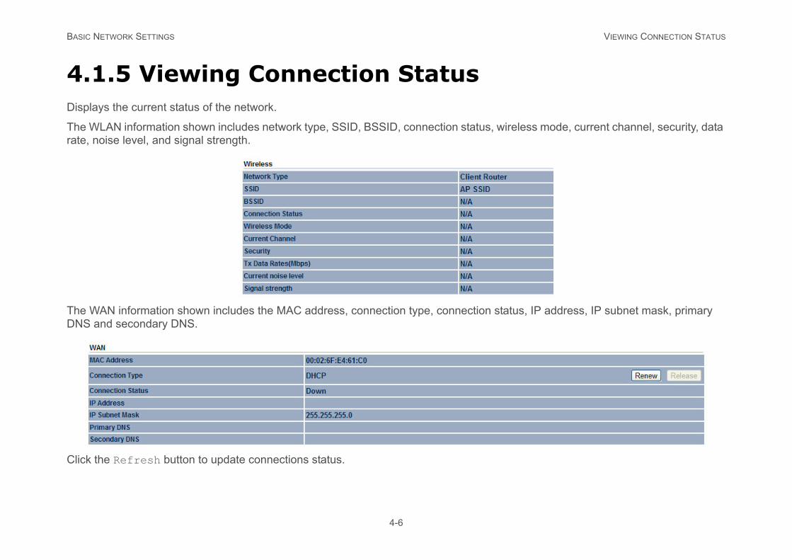
4.1.5 Viewing Connection StatusDisplays the current status of the network.
The WLAN information shown includes network type, SSID, BSSID, connection status, wireless mode, current channel, security, data rate, noise level, and signal strength.
The WAN information shown includes the MAC address, connection type, connection status, IP address, IP subnet mask, primary DNS and secondary DNS.
Click the Refresh button to update connections status.
BASIC NETWORK SETTINGS VIEWING DHCP CLIENT TABLE
4-7
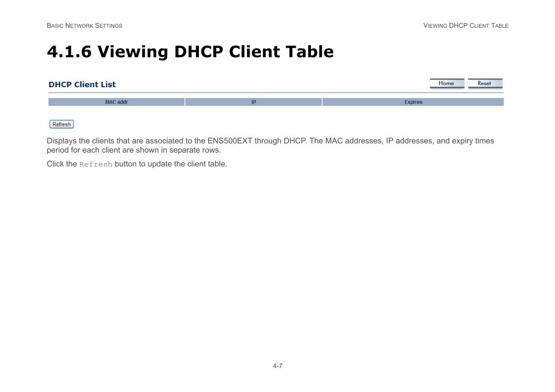
4.1.6 Viewing DHCP Client Table
Displays the clients that are associated to the ENS500EXT through DHCP. The MAC addresses, IP addresses, and expiry times period for each client are shown in separate rows.
Click the Refresh button to update the client table.
BASIC NETWORK SETTINGS VIEWING WDS LINK LIST
4-8
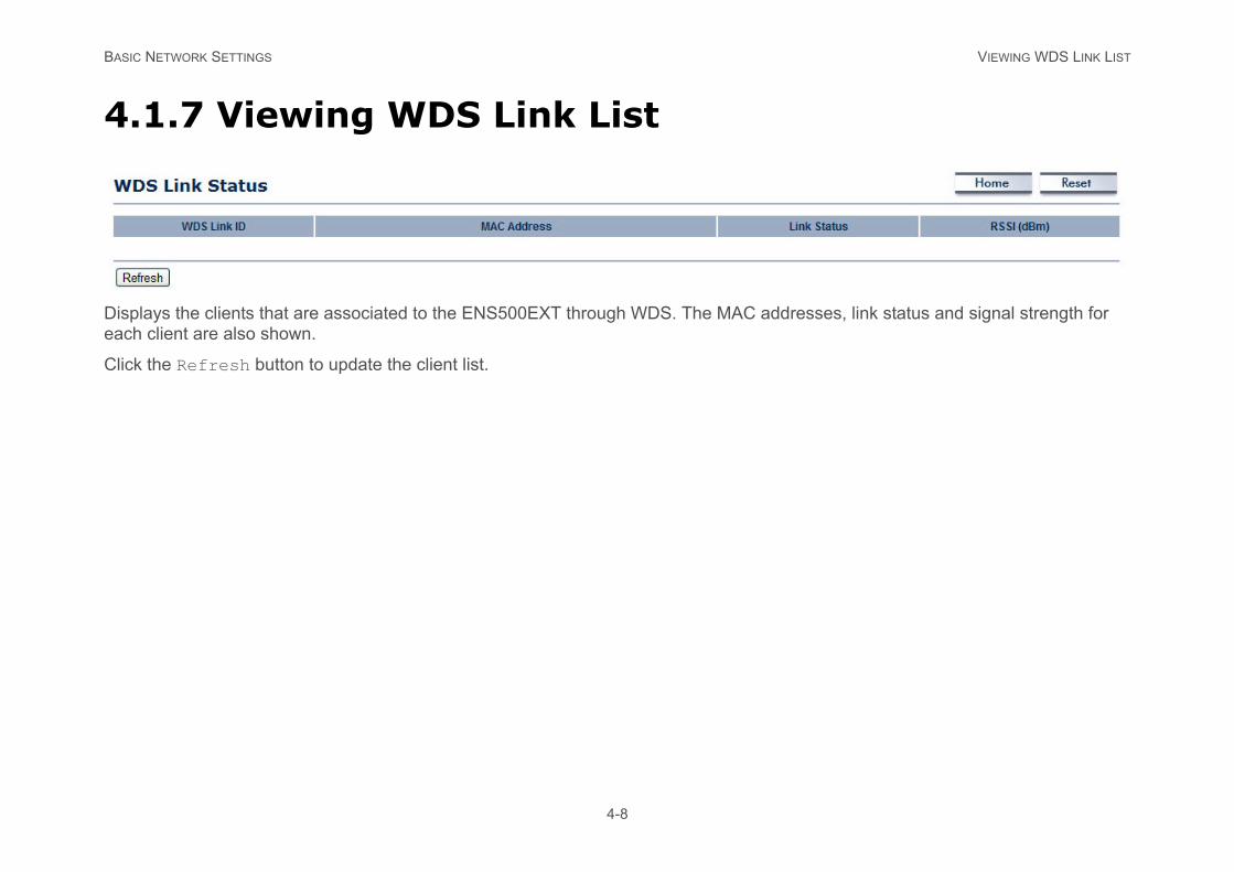
4.1.7 Viewing WDS Link List
Displays the clients that are associated to the ENS500EXT through WDS. The MAC addresses, link status and signal strength for each client are also shown.
Click the Refresh button to update the client list.
BASIC NETWORK SETTINGS SYSTEM SETUP
4-9
4.2 System Setup
The following sections explain the features and functionality of the ENS500EXT in access point mode, client bridge mode, WDS access point mode, WDS bridge mode, WDS station mode and client router mode.
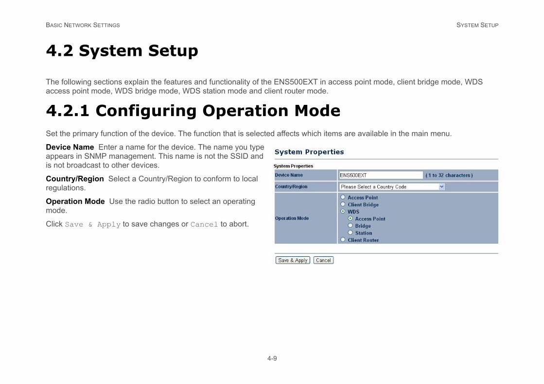
4.2.1 Configuring Operation ModeSet the primary function of the device. The function that is selected affects which items are available in the main menu.
Device Name Enter a name for the device. The name you type appears in SNMP management. This name is not the SSID and is not broadcast to other devices.
Country/Region Select a Country/Region to conform to local regulations.
Operation Mode Use the radio button to select an operating mode.
Click Save & Apply to save changes or Cancel to abort.
BASIC NETWORK SETTINGS CONFIGURING IP SETTINGS
4-10
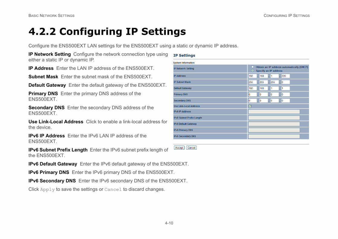
4.2.2 Configuring IP SettingsConfigure the ENS500EXT LAN settings for the ENS500EXT using a static or dynamic IP address.
IP Network Setting Configure the network connection type using either a static IP or dynamic IP.
IP Address Enter the LAN IP address of the ENS500EXT.
Subnet Mask Enter the subnet mask of the ENS500EXT.
Default Gateway Enter the default gateway of the ENS500EXT.
Primary DNS Enter the primary DNS address of the ENS500EXT.
Secondary DNS Enter the secondary DNS address of the ENS500EXT.
Use Link-Local Address Click to enable a link-local address for the device.
IPv6 IP Address Enter the IPv6 LAN IP address of the ENS500EXT.
IPv6 Subnet Prefix Length Enter the IPv6 subnet prefix length of the ENS500EXT.
IPv6 Default Gateway Enter the IPv6 default gateway of the ENS500EXT.
IPv6 Primary DNS Enter the IPv6 primary DNS of the ENS500EXT.
IPv6 Secondary DNS Enter the IPv6 secondary DNS of the ENS500EXT.
Click Apply to save the settings or Cancel to discard changes.
BASIC NETWORK SETTINGS CONFIGURING SPANNING TREE SETTINGS
4-11
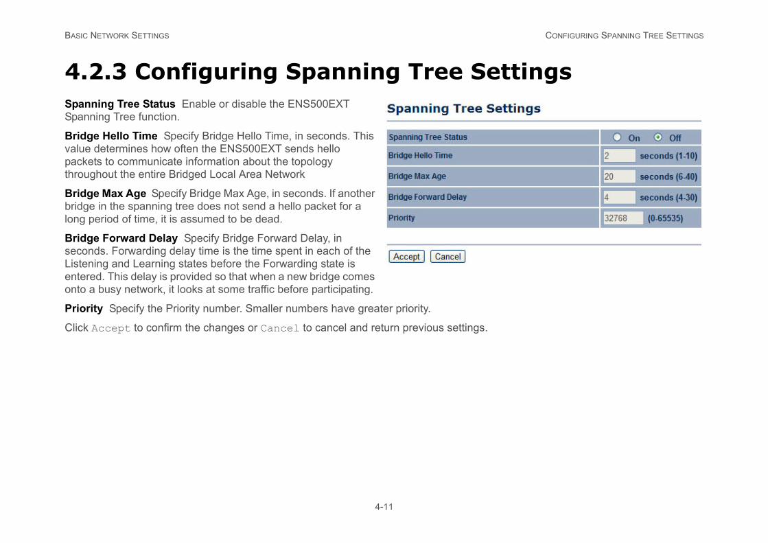
4.2.3 Configuring Spanning Tree SettingsSpanning Tree Status Enable or disable the ENS500EXT Spanning Tree function.
Bridge Hello Time Specify Bridge Hello Time, in seconds. This value determines how often the ENS500EXT sends hello packets to communicate information about the topology throughout the entire Bridged Local Area Network
Bridge Max Age Specify Bridge Max Age, in seconds. If another bridge in the spanning tree does not send a hello packet for a long period of time, it is assumed to be dead.
Bridge Forward Delay Specify Bridge Forward Delay, in seconds. Forwarding delay time is the time spent in each of the Listening and Learning states before the Forwarding state is entered. This delay is provided so that when a new bridge comes onto a busy network, it looks at some traffic before participating.
Priority Specify the Priority number. Smaller numbers have greater priority.
Click Accept to confirm the changes or Cancel to cancel and return previous settings.
BASIC NETWORK SETTINGS ROUTER SETUP
PPoE or PPTP.
4-12
4.3 Router Setup
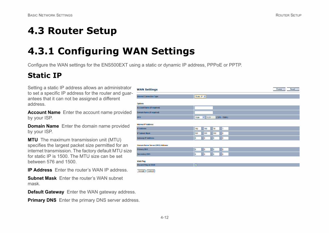
4.3.1 Configuring WAN SettingsConfigure the WAN settings for the ENS500EXT using a static or dynamic IP address, P
Static IP
Setting a static IP address allows an administrator to set a specific IP address for the router and guar-antees that it can not be assigned a different address.
Account Name Enter the account name provided by your ISP.
Domain Name Enter the domain name provided by your ISP.
MTU The maximum transmission unit (MTU) specifies the largest packet size permitted for an internet transmission. The factory default MTU size for static IP is 1500. The MTU size can be set between 576 and 1500.
IP Address Enter the router’s WAN IP address.
Subnet Mask Enter the router’s WAN subnet mask.
Default Gateway Enter the WAN gateway address.
Primary DNS Enter the primary DNS server address.
BASIC NETWORK SETTINGS DYNAMIC IP
nterface or Disable to block pings on the hackers to test whether the IP address is
m the ISP.
ary DNS servers manually.
nterface or Disable to block pings on the hackers to test whether the IP address is
4-13
Secondary DNS Enter the secondary DNS server address.
Discard Ping on WAN Check to Enable to recognize pings on the ENS500EXT WAN iENS500EXT WAN interface. Note: Pinging IP addresses is a common method used by valid. Blocking pings provides some extra security from hackers.
Click Accept to save the settings or Cancel to discard changes.
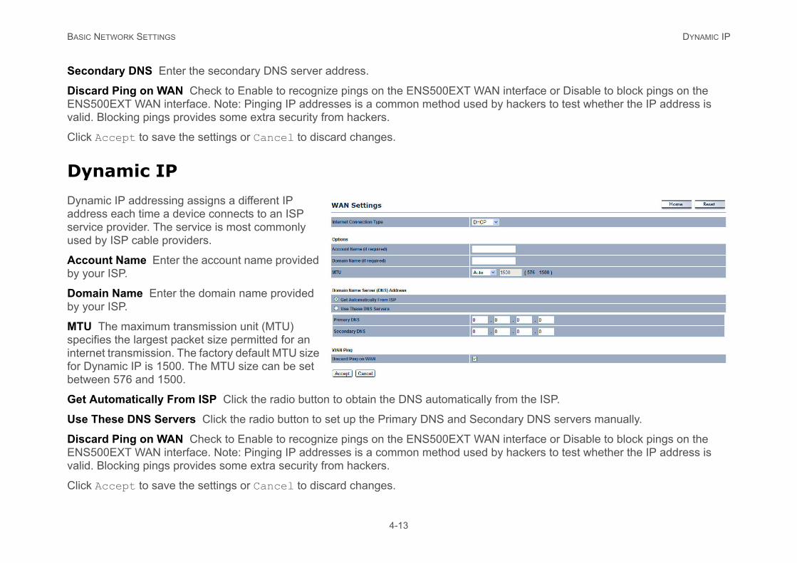
Dynamic IP
Dynamic IP addressing assigns a different IP address each time a device connects to an ISP service provider. The service is most commonly used by ISP cable providers.
Account Name Enter the account name provided by your ISP.
Domain Name Enter the domain name provided by your ISP.
MTU The maximum transmission unit (MTU) specifies the largest packet size permitted for an internet transmission. The factory default MTU size for Dynamic IP is 1500. The MTU size can be set between 576 and 1500.
Get Automatically From ISP Click the radio button to obtain the DNS automatically fro
Use These DNS Servers Click the radio button to set up the Primary DNS and Second
Discard Ping on WAN Check to Enable to recognize pings on the ENS500EXT WAN iENS500EXT WAN interface. Note: Pinging IP addresses is a common method used by valid. Blocking pings provides some extra security from hackers.
Click Accept to save the settings or Cancel to discard changes.
BASIC NETWORK SETTINGS POINT-TO-POINT PROTOCOL OVER ETHERNET (PPPOE)
period once the internet lose connection.
m the DHCP server.
ary DNS servers manually.
nterface or Disable to block pings on the hackers to test whether the IP address is
4-14
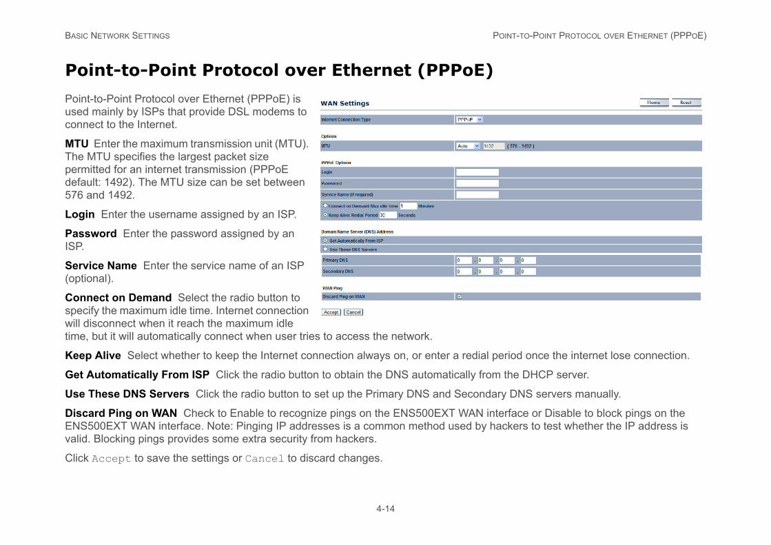
Point-to-Point Protocol over Ethernet (PPPoE)
Point-to-Point Protocol over Ethernet (PPPoE) is used mainly by ISPs that provide DSL modems to connect to the Internet.
MTU Enter the maximum transmission unit (MTU). The MTU specifies the largest packet size permitted for an internet transmission (PPPoE default: 1492). The MTU size can be set between 576 and 1492.
Login Enter the username assigned by an ISP.
Password Enter the password assigned by an ISP.
Service Name Enter the service name of an ISP (optional).
Connect on Demand Select the radio button to specify the maximum idle time. Internet connection will disconnect when it reach the maximum idle time, but it will automatically connect when user tries to access the network.
Keep Alive Select whether to keep the Internet connection always on, or enter a redial
Get Automatically From ISP Click the radio button to obtain the DNS automatically fro
Use These DNS Servers Click the radio button to set up the Primary DNS and Second
Discard Ping on WAN Check to Enable to recognize pings on the ENS500EXT WAN iENS500EXT WAN interface. Note: Pinging IP addresses is a common method used by valid. Blocking pings provides some extra security from hackers.
Click Accept to save the settings or Cancel to discard changes.
BASIC NETWORK SETTINGS POINT-TO-POINT TUNNELLING PROTOCOL (PPTP)
it has been inactive for a period of time, st.
select this option. Then specify how often e ENS500EXT automatically re-establishes
4-15
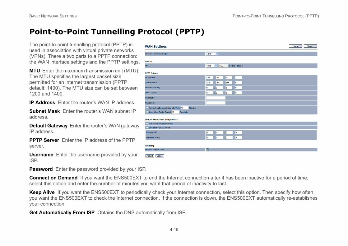
Point-to-Point Tunnelling Protocol (PPTP)
The point-to-point tunnelling protocol (PPTP) is used in association with virtual private networks (VPNs). There a two parts to a PPTP connection: the WAN interface settings and the PPTP settings.
MTU Enter the maximum transmission unit (MTU). The MTU specifies the largest packet size permitted for an internet transmission (PPTP default: 1400). The MTU size can be set between 1200 and 1400.
IP Address Enter the router’s WAN IP address.
Subnet Mask Enter the router’s WAN subnet IP address.
Default Gateway Enter the router’s WAN gateway IP address.
PPTP Server Enter the IP address of the PPTP server.
Username Enter the username provided by your ISP.
Password Enter the password provided by your ISP.
Connect on Demand If you want the ENS500EXT to end the Internet connection after select this option and enter the number of minutes you want that period of inactivity to la
Keep Alive If you want the ENS500EXT to periodically check your Internet connection,you want the ENS500EXT to check the Internet connection. If the connection is down, thyour connection
Get Automatically From ISP Obtains the DNS automatically from ISP.

BASIC NETWORK SETTINGS POINT-TO-POINT TUNNELLING PROTOCOL (PPTP)
ary DNS servers manually.
nterface or Disable to block pings on the hackers to test whether the IP address is
4-16
Use These DNS Servers Click the radio button to set up the Primary DNS and Second
Discard Ping on WAN Check to Enable to recognize pings on the ENS500EXT WAN iENS500EXT WAN interface. Note: Pinging IP addresses is a common method used by valid. Blocking pings provides some extra security from hackers.
Click Accept to save the settings or Cancel to discard changes.
BASIC NETWORK SETTINGS CONFIGURING LAN SETTINGS
4-17
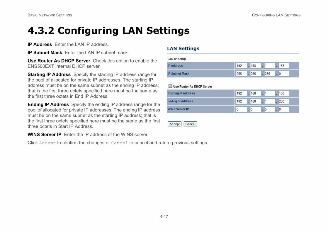
4.3.2 Configuring LAN SettingsIP Address Enter the LAN IP address.
IP Subnet Mask Enter the LAN IP subnet mask.
Use Router As DHCP Server Check this option to enable the ENS500EXT internal DHCP server.
Starting IP Address Specify the starting IP address range for the pool of allocated for private IP addresses. The starting IP address must be on the same subnet as the ending IP address; that is the first three octets specified here must be the same as the first three octets in End IP Address.
Ending IP Address Specify the ending IP address range for the pool of allocated for private IP addresses. The ending IP address must be on the same subnet as the starting IP address; that is the first three octets specified here must be the same as the first three octets in Start IP Address.
WINS Server IP Enter the IP address of the WINS server.
Click Accept to confirm the changes or Cancel to cancel and return previous settings.
BASIC NETWORK SETTINGS CONFIGURING VPN PASS-THROUGH
4-18
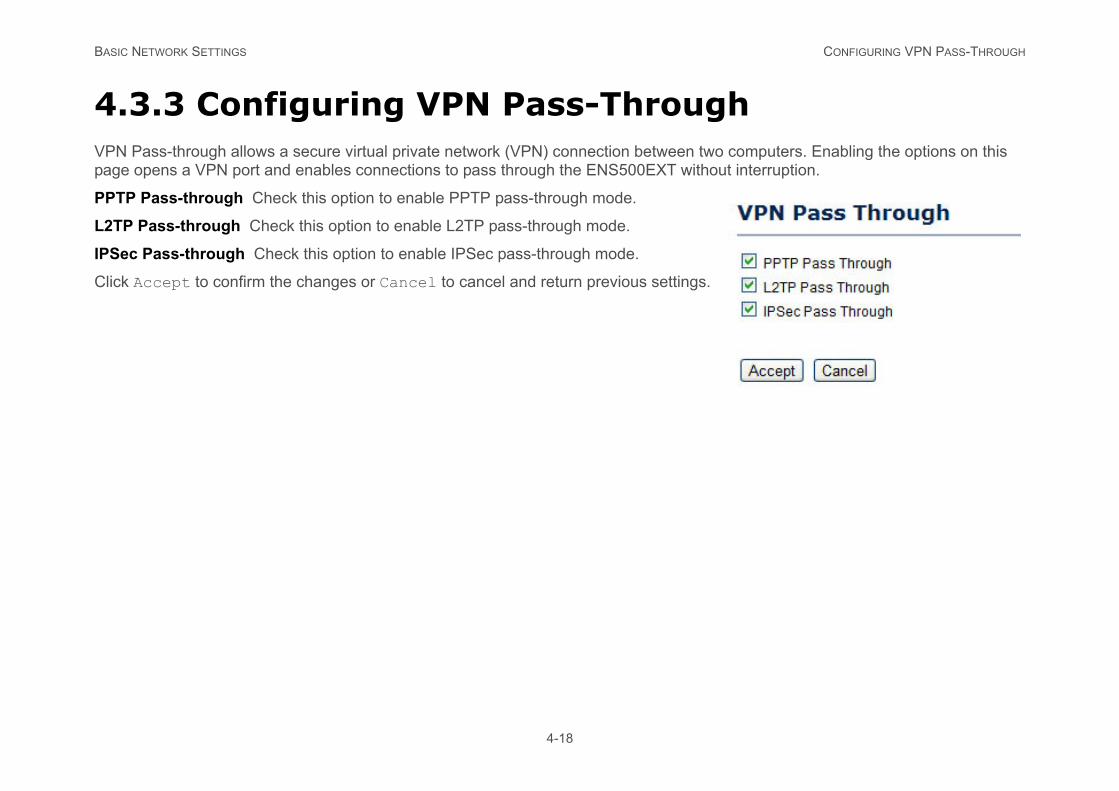
4.3.3 Configuring VPN Pass-ThroughVPN Pass-through allows a secure virtual private network (VPN) connection between two computers. Enabling the options on this page opens a VPN port and enables connections to pass through the ENS500EXT without interruption.
PPTP Pass-through Check this option to enable PPTP pass-through mode.
L2TP Pass-through Check this option to enable L2TP pass-through mode.
IPSec Pass-through Check this option to enable IPSec pass-through mode.
Click Accept to confirm the changes or Cancel to cancel and return previous settings.
BASIC NETWORK SETTINGS CONFIGURING PORT FORWARDING
over a single WAN IP address. The router ort and protocol and forwards the packets to devices behind the firewall.
h.
4-19
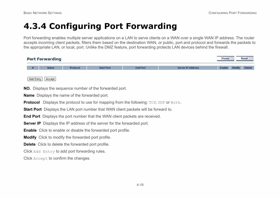
4.3.4 Configuring Port ForwardingPort forwarding enables multiple server applications on a LAN to serve clients on a WANaccepts incoming client packets, filters them based on the destination WAN, or public, pthe appropriate LAN, or local, port. Unlike the DMZ feature, port forwarding protects LAN
NO. Displays the sequence number of the forwarded port.
Name Displays the name of the forwarded port.
Protocol Displays the protocol to use for mapping from the following: TCP, UDP or Bot
Start Port Displays the LAN port number that WAN client packets will be forward to.
End Port Displays the port number that the WAN client packets are received.
Server IP Displays the IP address of the server for the forwarded port.
Enable Click to enable or disable the forwarded port profile.
Modify Click to modify the forwarded port profile.
Delete Click to delete the forwarded port profile.
Click Add Entry to add port forwarding rules.
Click Accept to confirm the changes.
BASIC NETWORK SETTINGS CONFIGURING PORT FORWARDING
4-20
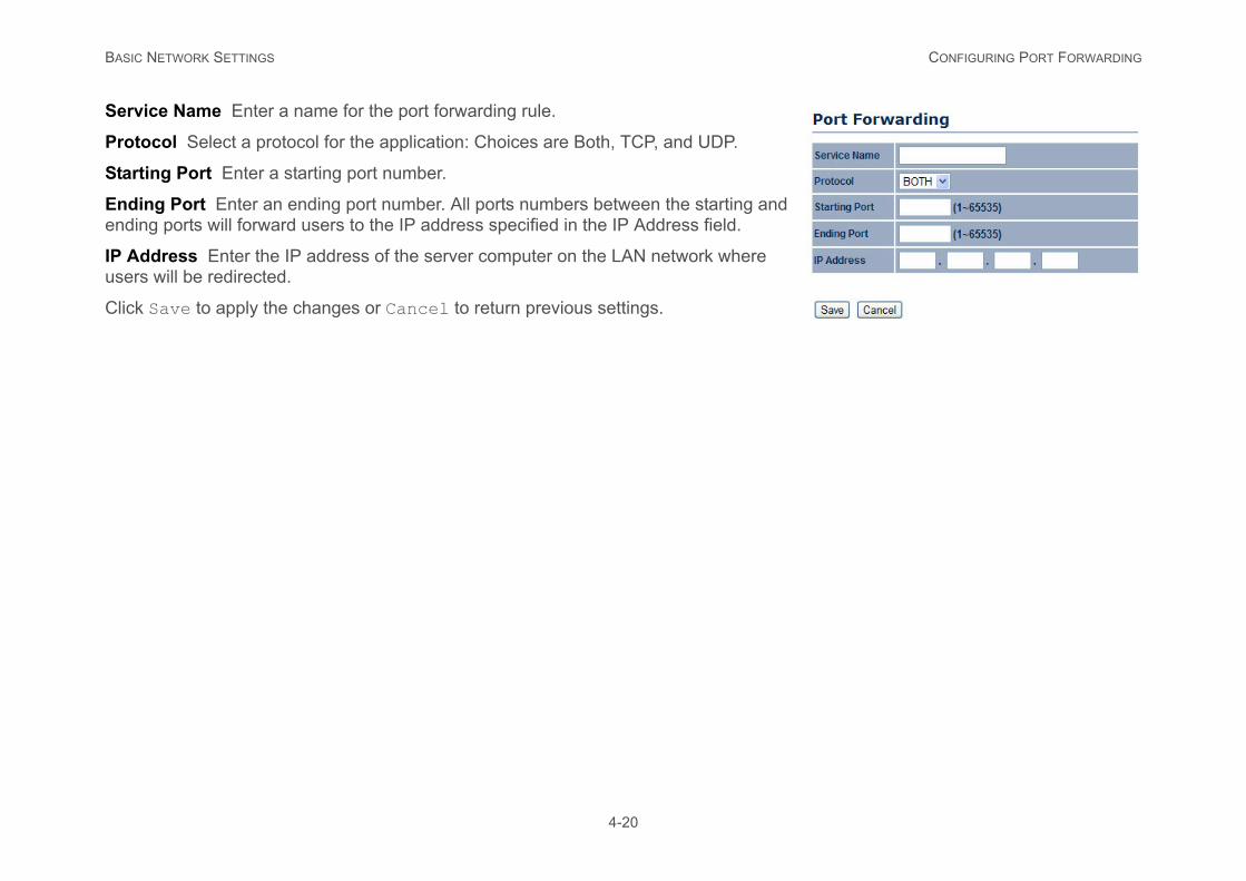
Service Name Enter a name for the port forwarding rule.
Protocol Select a protocol for the application: Choices are Both, TCP, and UDP.
Starting Port Enter a starting port number.
Ending Port Enter an ending port number. All ports numbers between the starting and ending ports will forward users to the IP address specified in the IP Address field.
IP Address Enter the IP address of the server computer on the LAN network where users will be redirected.
Click Save to apply the changes or Cancel to return previous settings.
BASIC NETWORK SETTINGS CONFIGURING DEMILITARIZED ZONE
4-21
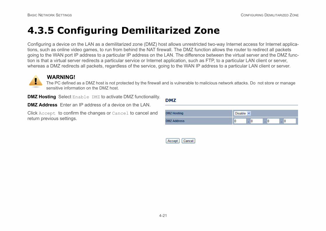
4.3.5 Configuring Demilitarized ZoneConfiguring a device on the LAN as a demilitarized zone (DMZ) host allows unrestricted two-way Internet access for Internet applica-tions, such as online video games, to run from behind the NAT firewall. The DMZ function allows the router to redirect all packets going to the WAN port IP address to a particular IP address on the LAN. The difference between the virtual server and the DMZ func-tion is that a virtual server redirects a particular service or Internet application, such as FTP, to a particular LAN client or server, whereas a DMZ redirects all packets, regardless of the service, going to the WAN IP address to a particular LAN client or server.
DMZ Hosting Select Enable DMZ to activate DMZ functionality.
DMZ Address Enter an IP address of a device on the LAN.
Click Accept to confirm the changes or Cancel to cancel and return previous settings.
WARNING!The PC defined as a DMZ host is not protected by the firewall and is vulnerable to malicious network attacks. Do not store or manage sensitive information on the DMZ host.
!
BASIC NETWORK SETTINGS CONFIGURING WIRELESS LAN
sle operating modes.
t device within range can connect to the
odify the settings in this section without a thor-
4-22
4.4 Configuring Wireless LAN
4.4.1 Configuring Wireless SettingInstructions on how to configure the wireless and security settings for each of the possib
Access Point Mode
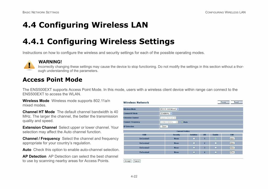
The ENS500EXT supports Access Point Mode. In this mode, users with a wireless clienENS500EXT to access the WLAN.
Wireless Mode Wireless mode supports 802.11a/n mixed modes.
Channel HT Mode The default channel bandwidth is 40 MHz. The larger the channel, the better the transmission quality and speed.
Extension Channel Select upper or lower channel. Your selection may affect the Auto channel function.
Channel / Frequency Select the channel and frequency appropriate for your country’s regulation.
Auto Check this option to enable auto-channel selection.
AP Detection AP Detection can select the best channel to use by scanning nearby areas for Access Points.
WARNING!Incorrectly changing these settings may cause the device to stop functioning. Do not mough understanding of the parameters.
!
BASIC NETWORK SETTINGS ACCESS POINT MODE
ssing the network, you can arrange the nt to enable extra SSIDs.
4-23
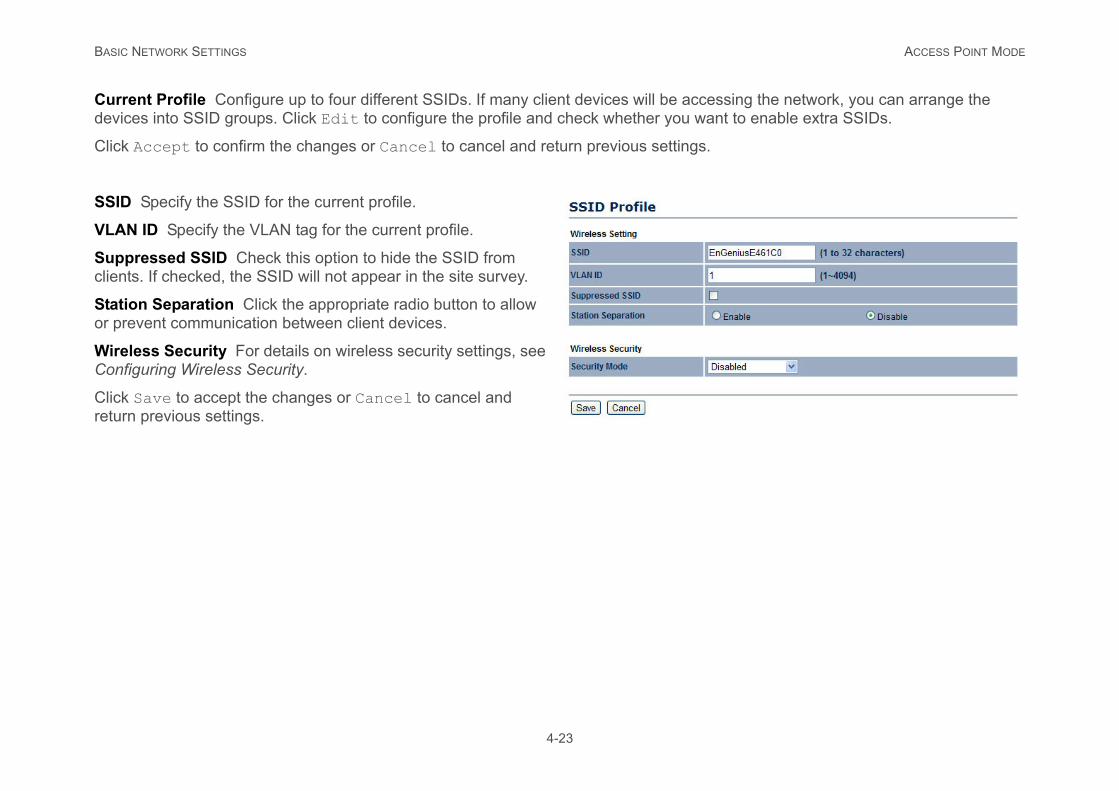
Current Profile Configure up to four different SSIDs. If many client devices will be accedevices into SSID groups. Click Edit to configure the profile and check whether you wa
Click Accept to confirm the changes or Cancel to cancel and return previous settings.
SSID Specify the SSID for the current profile.
VLAN ID Specify the VLAN tag for the current profile.
Suppressed SSID Check this option to hide the SSID from clients. If checked, the SSID will not appear in the site survey.
Station Separation Click the appropriate radio button to allow or prevent communication between client devices.
Wireless Security For details on wireless security settings, see Configuring Wireless Security.
Click Save to accept the changes or Cancel to cancel and return previous settings.
BASIC NETWORK SETTINGS CLIENT BRIDGE MODE
y are on the same physical network. Since P information generated by the server reach
4-24
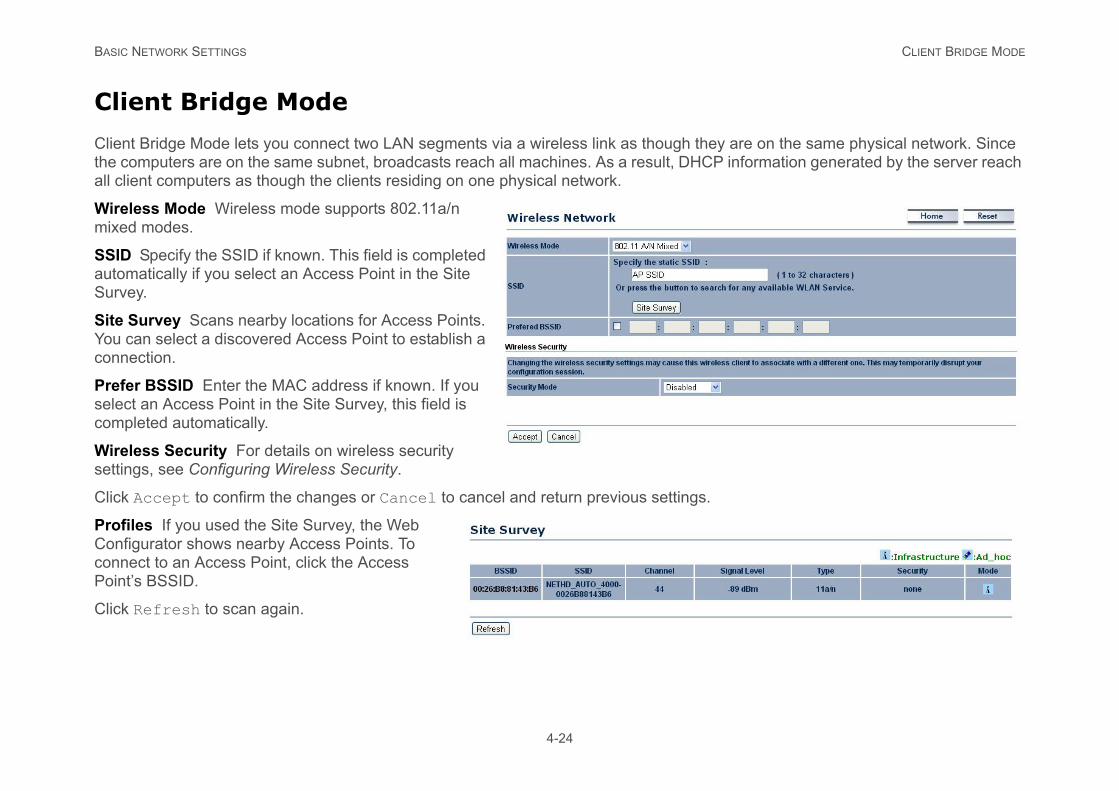
Client Bridge Mode
Client Bridge Mode lets you connect two LAN segments via a wireless link as though thethe computers are on the same subnet, broadcasts reach all machines. As a result, DHCall client computers as though the clients residing on one physical network.
Wireless Mode Wireless mode supports 802.11a/n mixed modes.
SSID Specify the SSID if known. This field is completed automatically if you select an Access Point in the Site Survey.
Site Survey Scans nearby locations for Access Points. You can select a discovered Access Point to establish a connection.
Prefer BSSID Enter the MAC address if known. If you select an Access Point in the Site Survey, this field is completed automatically.
Wireless Security For details on wireless security settings, see Configuring Wireless Security.
Click Accept to confirm the changes or Cancel to cancel and return previous settings.
Profiles If you used the Site Survey, the Web Configurator shows nearby Access Points. To connect to an Access Point, click the Access Point’s BSSID.
Click Refresh to scan again.
BASIC NETWORK SETTINGS WDS BRIDGE MODE
ks by linking several wireless access points rohibitive, restricted or physically impossible.
4-25
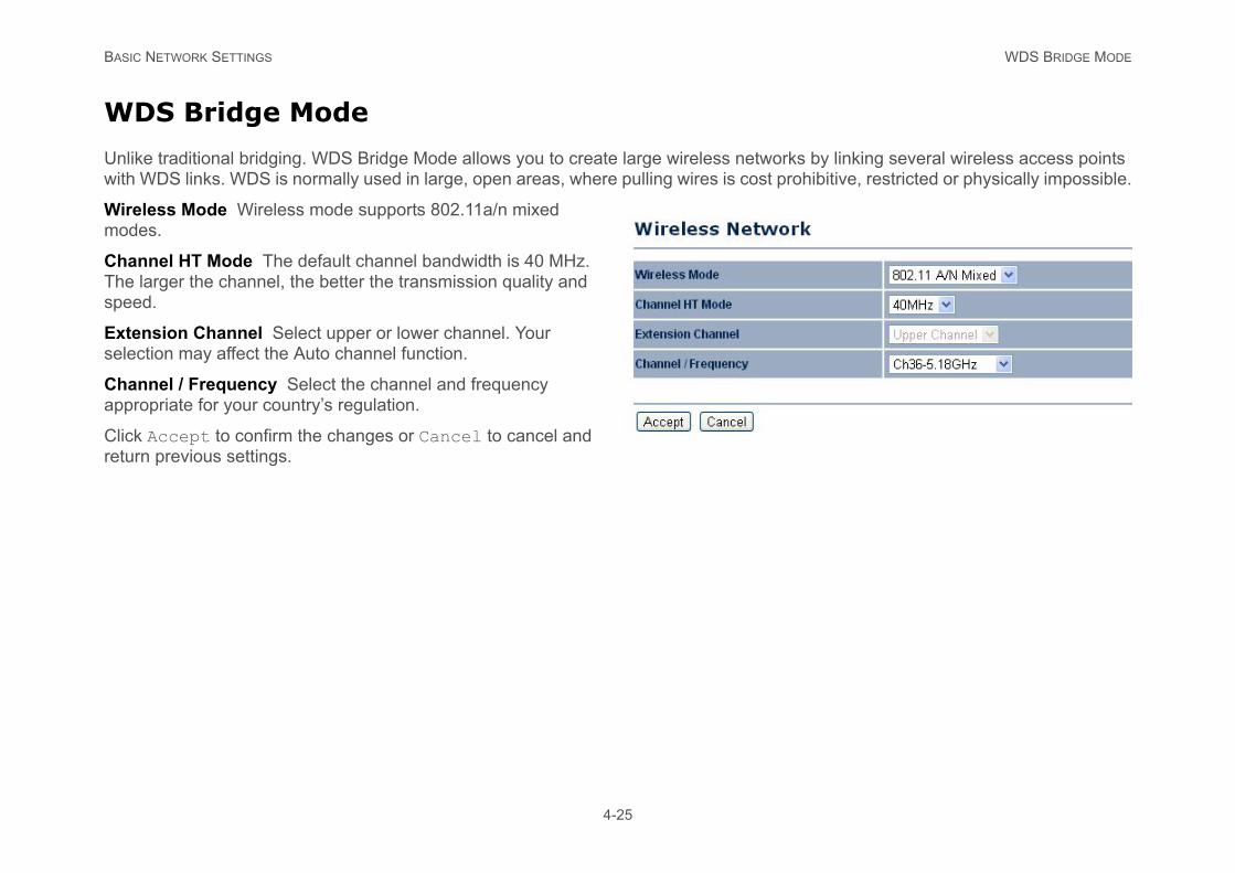
WDS Bridge Mode
Unlike traditional bridging. WDS Bridge Mode allows you to create large wireless networwith WDS links. WDS is normally used in large, open areas, where pulling wires is cost p
Wireless Mode Wireless mode supports 802.11a/n mixed modes.
Channel HT Mode The default channel bandwidth is 40 MHz. The larger the channel, the better the transmission quality and speed.
Extension Channel Select upper or lower channel. Your selection may affect the Auto channel function.
Channel / Frequency Select the channel and frequency appropriate for your country’s regulation.
Click Accept to confirm the changes or Cancel to cancel and return previous settings.
BASIC NETWORK SETTINGS WDS BRIDGE MODE
4-26
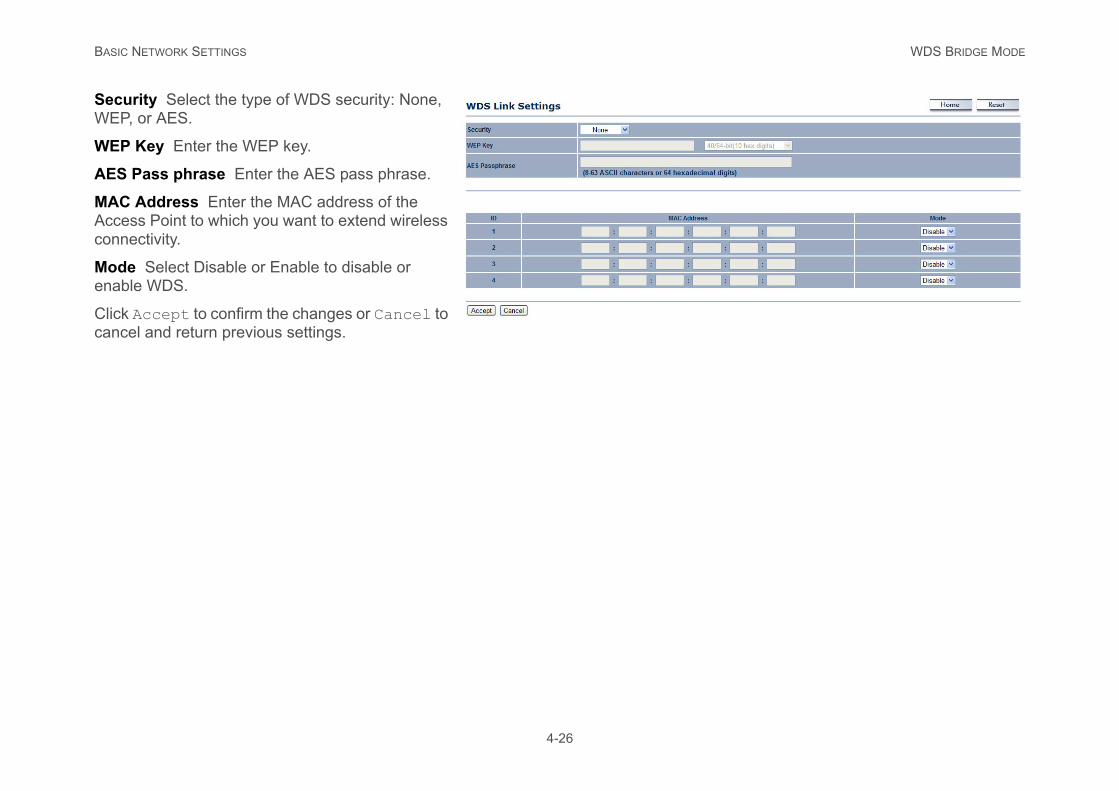
Security Select the type of WDS security: None, WEP, or AES.
WEP Key Enter the WEP key.
AES Pass phrase Enter the AES pass phrase.
MAC Address Enter the MAC address of the Access Point to which you want to extend wireless connectivity.
Mode Select Disable or Enable to disable or enable WDS.
Click Accept to confirm the changes or Cancel to cancel and return previous settings.
BASIC NETWORK SETTINGS CLIENT ROUTER MODE
. It also supports VPN pass-through for sen-
4-27
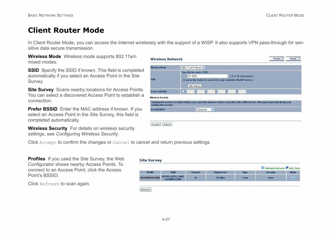
Client Router Mode
In Client Router Mode, you can access the Internet wirelessly with the support of a WISPsitive data secure transmission.
Wireless Mode Wireless mode supports 802.11a/n mixed modes.
SSID Specify the SSID if known. This field is completed automatically if you select an Access Point in the Site Survey.
Site Survey Scans nearby locations for Access Points. You can select a discovered Access Point to establish a connection.
Prefer BSSID Enter the MAC address if known. If you select an Access Point in the Site Survey, this field is completed automatically.
Wireless Security For details on wireless security settings, see Configuring Wireless Security.
Click Accept to confirm the changes or Cancel to cancel and return previous settings.
Profiles If you used the Site Survey, the Web Configurator shows nearby Access Points. To connect to an Access Point, click the Access Point’s BSSID.
Click Refresh to scan again.
BASIC NETWORK SETTINGS CONFIGURING WIRELESS SECURITY
des: WEP, WPA-PSK, WPA2-PSK, WPA-K.
nnection mode will change from 802.11n to
4-28
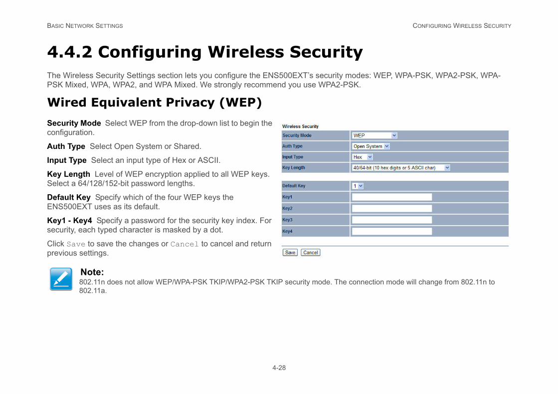
4.4.2 Configuring Wireless SecurityThe Wireless Security Settings section lets you configure the ENS500EXT’s security moPSK Mixed, WPA, WPA2, and WPA Mixed. We strongly recommend you use WPA2-PS
Wired Equivalent Privacy (WEP)
Security Mode Select WEP from the drop-down list to begin the configuration.
Auth Type Select Open System or Shared.
Input Type Select an input type of Hex or ASCII.
Key Length Level of WEP encryption applied to all WEP keys. Select a 64/128/152-bit password lengths.
Default Key Specify which of the four WEP keys the ENS500EXT uses as its default.
Key1 - Key4 Specify a password for the security key index. For security, each typed character is masked by a dot.
Click Save to save the changes or Cancel to cancel and return previous settings.
Note:802.11n does not allow WEP/WPA-PSK TKIP/WPA2-PSK TKIP security mode. The co802.11a.
BASIC NETWORK SETTINGS WI-FI PROTECTED ACCESS PRE-SHARED KEY (WPA-PSK)
PSK)
ed by a dot.
nnection mode will change from 802.11n to
4-29
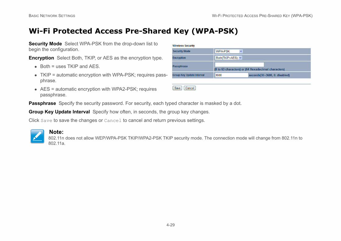
Wi-Fi Protected Access Pre-Shared Key (WPA-
Security Mode Select WPA-PSK from the drop-down list to begin the configuration.
Encryption Select Both, TKIP, or AES as the encryption type.
Both = uses TKIP and AES.
TKIP = automatic encryption with WPA-PSK; requires pass-phrase.
AES = automatic encryption with WPA2-PSK; requires passphrase.
Passphrase Specify the security password. For security, each typed character is mask
Group Key Update Interval Specify how often, in seconds, the group key changes.
Click Save to save the changes or Cancel to cancel and return previous settings.
Note:802.11n does not allow WEP/WPA-PSK TKIP/WPA2-PSK TKIP security mode. The co802.11a.
BASIC NETWORK SETTINGS WI-FI PROTECTED ACCESS 2 PRE-SHARED KEY (WPA2-PSK)
A2-PSK)
ed by a dot.
nnection mode will change from 802.11n to
4-30
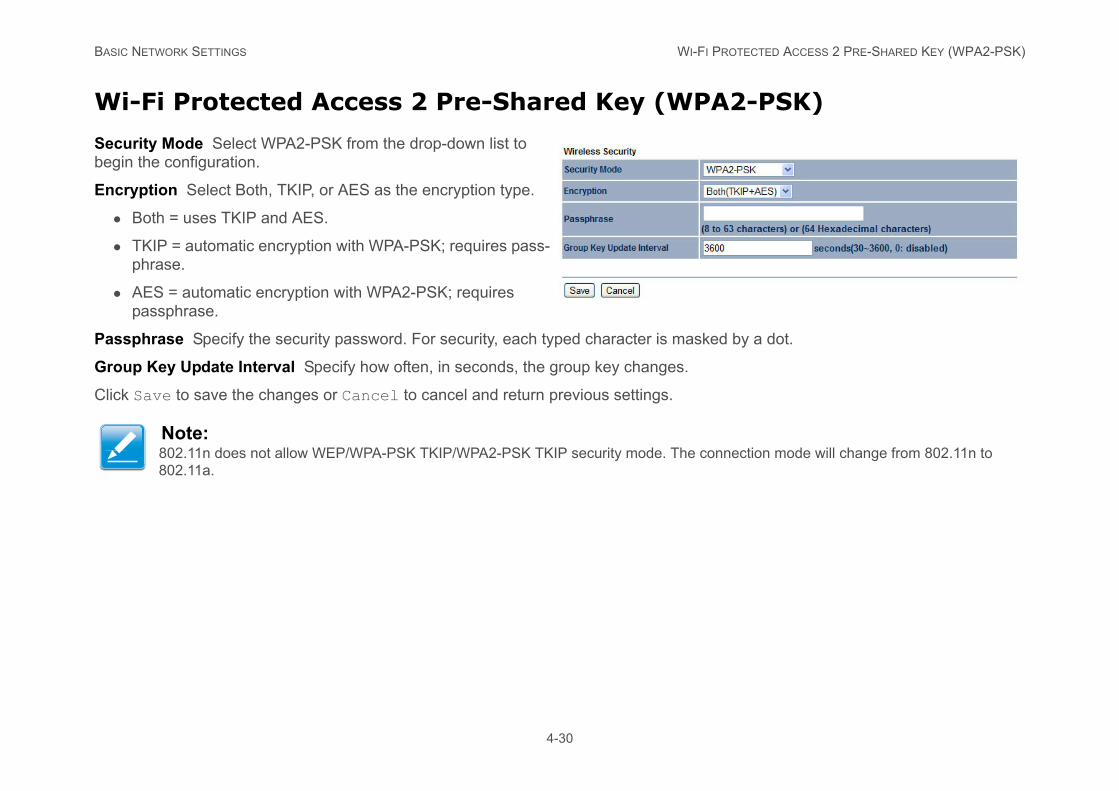
Wi-Fi Protected Access 2 Pre-Shared Key (WP
Security Mode Select WPA2-PSK from the drop-down list to begin the configuration.
Encryption Select Both, TKIP, or AES as the encryption type.
Both = uses TKIP and AES.
TKIP = automatic encryption with WPA-PSK; requires pass-phrase.
AES = automatic encryption with WPA2-PSK; requires passphrase.
Passphrase Specify the security password. For security, each typed character is mask
Group Key Update Interval Specify how often, in seconds, the group key changes.
Click Save to save the changes or Cancel to cancel and return previous settings.
Note:802.11n does not allow WEP/WPA-PSK TKIP/WPA2-PSK TKIP security mode. The co802.11a.
BASIC NETWORK SETTINGS WI-FI PROTECTED ACCESS PRE-SHARED KEY (WPA-PSK) MIXED
PSK) Mixed
ed by a dot.
t allow WEP/WPA-PSK TKIP/WPA2-PSK TKIP
4-31
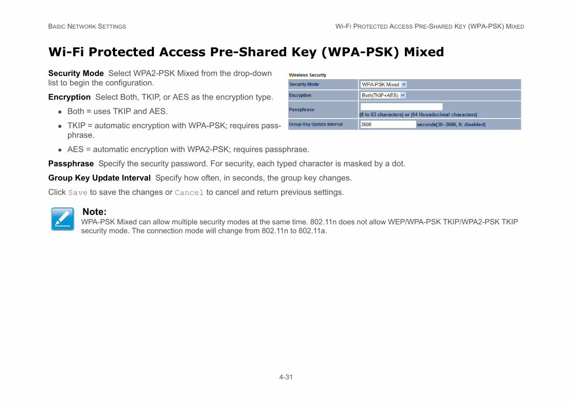
Wi-Fi Protected Access Pre-Shared Key (WPA-
Security Mode Select WPA2-PSK Mixed from the drop-down list to begin the configuration.
Encryption Select Both, TKIP, or AES as the encryption type.
Both = uses TKIP and AES.
TKIP = automatic encryption with WPA-PSK; requires pass-phrase.
AES = automatic encryption with WPA2-PSK; requires passphrase.
Passphrase Specify the security password. For security, each typed character is mask
Group Key Update Interval Specify how often, in seconds, the group key changes.
Click Save to save the changes or Cancel to cancel and return previous settings.
Note:WPA-PSK Mixed can allow multiple security modes at the same time. 802.11n does nosecurity mode. The connection mode will change from 802.11n to 802.11a.

BASIC NETWORK SETTINGS WI-FI PROTECTED ACCESS (WPA)
s for authentication. Default port is 1813.
server.
ction mode will change from 802.11n to
4-32
Wi-Fi Protected Access (WPA)
Security Mode Select WPA from the drop-down list to begin the configuration.
Encryption Select Both, TKIP, or AES as the encryption type.
Both = uses TKIP and AES.
TKIP = automatic encryption with WPA-PSK; requires pass-phrase.
AES = automatic encryption with WPA2-PSK; requires passphrase.
Radius Server Specify the IP address of the RADIUS server.
Radius Port Specify the port number that your RADIUS server uses for authentication. Default port is 1812.
Radius Secret Specify RADIUS secret furnished by the RADIUS server.
Group Key Update Interval Specify how often, in seconds, the group key changes.
Radius Accounting Select to enable or disable RADIUS accounting.
Radius Accounting Server Specify the IP address of the RADIUS accounting server.
Radius Accounting Port Specify the port number that your RADIUS accounting server use
Radius Accounting Secret Specify RADIUS accounting secret furnished by the RADIUS
Interem Accounting Interval Specify the interem accounting interval (60 - 600 seconds).
Click Save to save the changes or Cancel to cancel and return previous settings.
Note:802.11n does not allow WEP/WPA-PSK TKIP/WPA2-PSK TKIP security mode. The conne802.11a.
BASIC NETWORK SETTINGS WI-FI PROTECTED ACCESS 2 (WPA2)
es for authentication. Default port is 1813.
server.
ction mode will change from 802.11n to
4-33
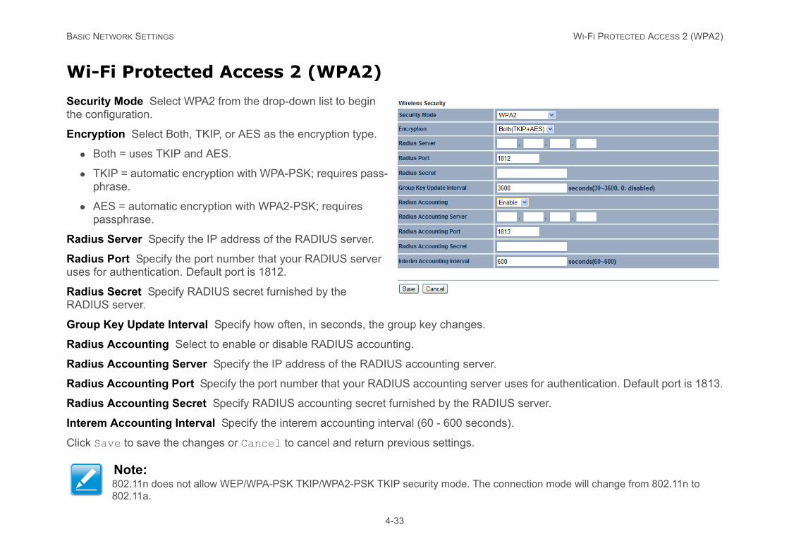
Wi-Fi Protected Access 2 (WPA2)
Security Mode Select WPA2 from the drop-down list to begin the configuration.
Encryption Select Both, TKIP, or AES as the encryption type.
Both = uses TKIP and AES.
TKIP = automatic encryption with WPA-PSK; requires pass-phrase.
AES = automatic encryption with WPA2-PSK; requires passphrase.
Radius Server Specify the IP address of the RADIUS server.
Radius Port Specify the port number that your RADIUS server uses for authentication. Default port is 1812.
Radius Secret Specify RADIUS secret furnished by the RADIUS server.
Group Key Update Interval Specify how often, in seconds, the group key changes.
Radius Accounting Select to enable or disable RADIUS accounting.
Radius Accounting Server Specify the IP address of the RADIUS accounting server.
Radius Accounting Port Specify the port number that your RADIUS accounting server us
Radius Accounting Secret Specify RADIUS accounting secret furnished by the RADIUS
Interem Accounting Interval Specify the interem accounting interval (60 - 600 seconds).
Click Save to save the changes or Cancel to cancel and return previous settings.
Note:802.11n does not allow WEP/WPA-PSK TKIP/WPA2-PSK TKIP security mode. The conne802.11a.
BASIC NETWORK SETTINGS WI-FI PROTECTED ACCESS (WPA) MIXED
es for authentication. Default port is 1813.
server.
low WEP/WPA-PSK TKIP/WPA2-PSK TKIP
4-34
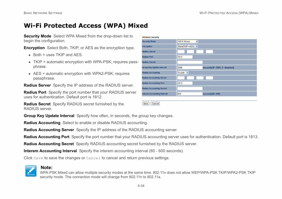
Wi-Fi Protected Access (WPA) Mixed
Security Mode Select WPA Mixed from the drop-down list to begin the configuration.
Encryption Select Both, TKIP, or AES as the encryption type.
Both = uses TKIP and AES.
TKIP = automatic encryption with WPA-PSK; requires pass-phrase.
AES = automatic encryption with WPA2-PSK; requires passphrase.
Radius Server Specify the IP address of the RADIUS server.
Radius Port Specify the port number that your RADIUS server uses for authentication. Default port is 1812.
Radius Secret Specify RADIUS secret furnished by the RADIUS server.
Group Key Update Interval Specify how often, in seconds, the group key changes.
Radius Accounting Select to enable or disable RADIUS accounting.
Radius Accounting Server Specify the IP address of the RADIUS accounting server.
Radius Accounting Port Specify the port number that your RADIUS accounting server us
Radius Accounting Secret Specify RADIUS accounting secret furnished by the RADIUS
Interem Accounting Interval Specify the interem accounting interval (60 - 600 seconds).
Click Save to save the changes or Cancel to cancel and return previous settings.
Note:WPA-PSK Mixed can allow multiple security modes at the same time. 802.11n does not alsecurity mode. The connection mode will change from 802.11n to 802.11a.
BASIC NETWORK SETTINGS CONFIGURING WIRELESS MAC FILTER
4-35
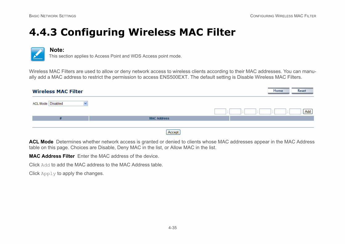
4.4.3 Configuring Wireless MAC Filter
Wireless MAC Filters are used to allow or deny network access to wireless clients according to their MAC addresses. You can manu-ally add a MAC address to restrict the permission to access ENS500EXT. The default setting is Disable Wireless MAC Filters.
ACL Mode Determines whether network access is granted or denied to clients whose MAC addresses appear in the MAC Address table on this page. Choices are Disable, Deny MAC in the list, or Allow MAC in the list.
MAC Address Filter Enter the MAC address of the device.
Click Add to add the MAC address to the MAC Address table.
Click Apply to apply the changes.
Note:This section applies to Access Point and WDS Access point mode.
BASIC NETWORK SETTINGS CONFIGURING WDS LINK SETTINGS
4-36
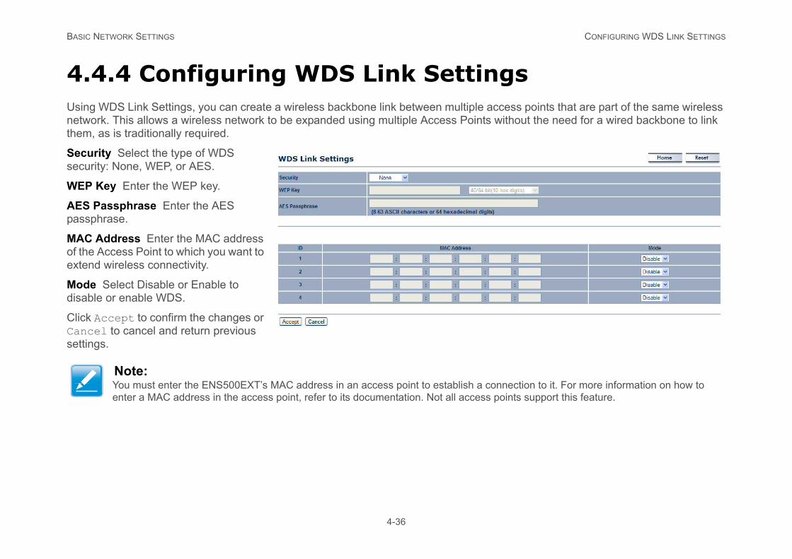
4.4.4 Configuring WDS Link SettingsUsing WDS Link Settings, you can create a wireless backbone link between multiple access points that are part of the same wireless network. This allows a wireless network to be expanded using multiple Access Points without the need for a wired backbone to link them, as is traditionally required.
Security Select the type of WDS security: None, WEP, or AES.
WEP Key Enter the WEP key.
AES Passphrase Enter the AES passphrase.
MAC Address Enter the MAC address of the Access Point to which you want to extend wireless connectivity.
Mode Select Disable or Enable to disable or enable WDS.
Click Accept to confirm the changes or Cancel to cancel and return previous settings.
Note:You must enter the ENS500EXT’s MAC address in an access point to establish a connection to it. For more information on how to enter a MAC address in the access point, refer to its documentation. Not all access points support this feature.
BASIC NETWORK SETTINGS CONFIGURING WIRELESS ADVANCED SETTINGS
ed Settingssection. Leave these settings to their default
es more bandwidth.
y drop high-speed connections.
packets, but increases packet sizes.
ific SSID.
4-37
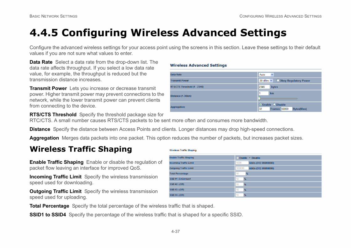
4.4.5 Configuring Wireless AdvancConfigure the advanced wireless settings for your access point using the screens in this values if you are not sure what values to enter.
Data Rate Select a data rate from the drop-down list. The data rate affects throughput. If you select a low data rate value, for example, the throughput is reduced but the transmission distance increases.
Transmit Power Lets you increase or decrease transmit power. Higher transmit power may prevent connections to the network, while the lower transmit power can prevent clients from connecting to the device.
RTS/CTS Threshold Specify the threshold package size for RTC/CTS. A small number causes RTS/CTS packets to be sent more often and consum
Distance Specify the distance between Access Points and clients. Longer distances ma
Aggregation Merges data packets into one packet. This option reduces the number of
Wireless Traffic Shaping
Enable Traffic Shaping Enable or disable the regulation of packet flow leaving an interface for improved QoS.
Incoming Traffic Limit Specify the wireless transmission speed used for downloading.
Outgoing Traffic Limit Specify the wireless transmission speed used for uploading.
Total Percentage Specify the total percentage of the wireless traffic that is shaped.
SSID1 to SSID4 Specify the percentage of the wireless traffic that is shaped for a spec
BASIC NETWORK SETTINGS CLIENT LIMIT
d to connect to this access point.
4-38
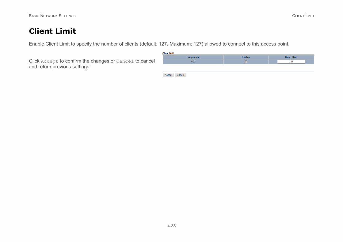
Client Limit
Enable Client Limit to specify the number of clients (default: 127, Maximum: 127) allowe
Click Accept to confirm the changes or Cancel to cancel and return previous settings.
BASIC NETWORK SETTINGS MANAGEMENT SETUP
4-39
4.5 Management Setup
The Management section lets you configure administration, management VLAN, SNMP settings, backup/restore settings, firmware upgrade, time settings, and log settings. This chapter describes these settings.
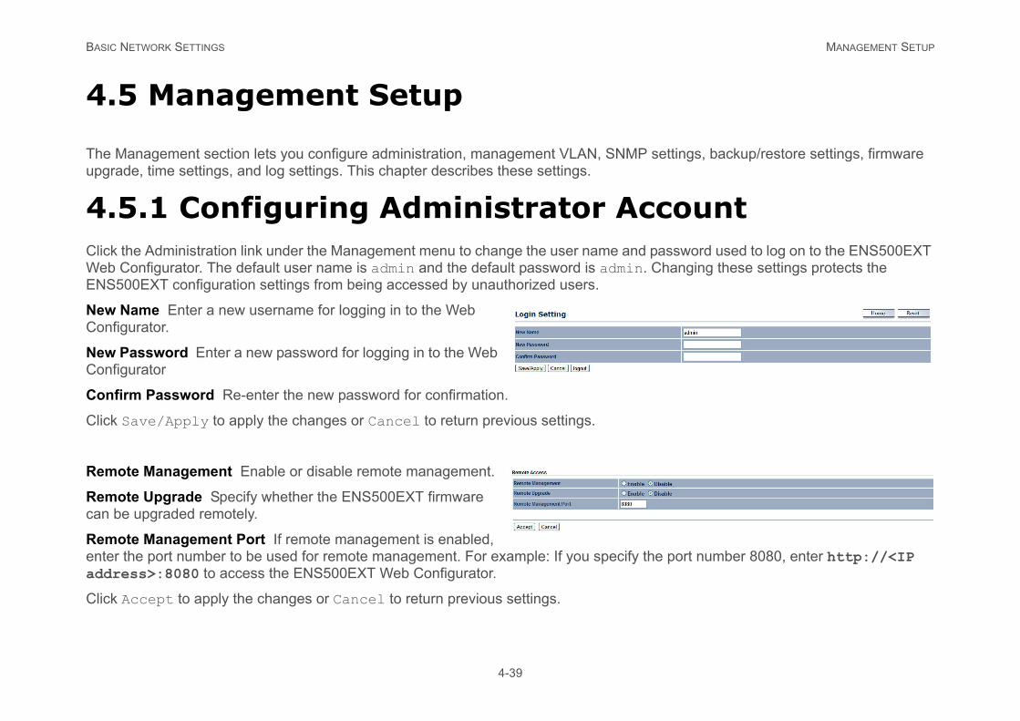
4.5.1 Configuring Administrator AccountClick the Administration link under the Management menu to change the user name and password used to log on to the ENS500EXT Web Configurator. The default user name is admin and the default password is admin. Changing these settings protects the ENS500EXT configuration settings from being accessed by unauthorized users.
New Name Enter a new username for logging in to the Web Configurator.
New Password Enter a new password for logging in to the Web Configurator
Confirm Password Re-enter the new password for confirmation.
Click Save/Apply to apply the changes or Cancel to return previous settings.
Remote Management Enable or disable remote management.
Remote Upgrade Specify whether the ENS500EXT firmware can be upgraded remotely.
Remote Management Port If remote management is enabled, enter the port number to be used for remote management. For example: If you specify the port number 8080, enter http://<IP address>:8080 to access the ENS500EXT Web Configurator.
Click Accept to apply the changes or Cancel to return previous settings.
BASIC NETWORK SETTINGS CONFIGURING MANAGEMENT VLAN
4-40
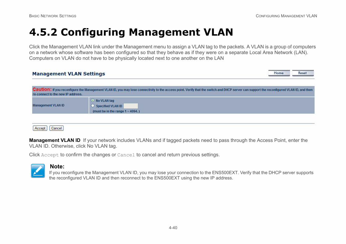
4.5.2 Configuring Management VLANClick the Management VLAN link under the Management menu to assign a VLAN tag to the packets. A VLAN is a group of computers on a network whose software has been configured so that they behave as if they were on a separate Local Area Network (LAN). Computers on VLAN do not have to be physically located next to one another on the LAN
Management VLAN ID If your network includes VLANs and if tagged packets need to pass through the Access Point, enter the VLAN ID. Otherwise, click No VLAN tag.
Click Accept to confirm the changes or Cancel to cancel and return previous settings.
Note:If you reconfigure the Management VLAN ID, you may lose your connection to the ENS500EXT. Verify that the DHCP server supports the reconfigured VLAN ID and then reconnect to the ENS500EXT using the new IP address.
BASIC NETWORK SETTINGS CONFIGURING SNMP
conditions that warrant administrative atten-
4-41
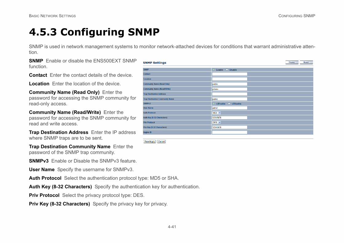
4.5.3 Configuring SNMPSNMP is used in network management systems to monitor network-attached devices fortion.
SNMP Enable or disable the ENS500EXT SNMP function.
Contact Enter the contact details of the device.
Location Enter the location of the device.
Community Name (Read Only) Enter the password for accessing the SNMP community for read-only access.
Community Name (Read/Write) Enter the password for accessing the SNMP community for read and write access.
Trap Destination Address Enter the IP address where SNMP traps are to be sent.
Trap Destination Community Name Enter the password of the SNMP trap community.
SNMPv3 Enable or Disable the SNMPv3 feature.
User Name Specify the username for SNMPv3.
Auth Protocol Select the authentication protocol type: MD5 or SHA.
Auth Key (8-32 Characters) Specify the authentication key for authentication.
Priv Protocol Select the privacy protocol type: DES.
Priv Key (8-32 Characters) Specify the privacy key for privacy.
BASIC NETWORK SETTINGS CONFIGURING SNMP
4-42
Engine ID Specify the engine ID for SNMPv3.
Click Save/Apply to apply the changes or Cancel to return previous settings.
BASIC NETWORK SETTINGS CONFIGURING BACKUP/RESTORE SETTINGS
4-43
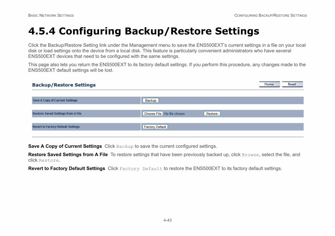
4.5.4 Configuring Backup/Restore SettingsClick the Backup/Restore Setting link under the Management menu to save the ENS500EXT’s current settings in a file on your local disk or load settings onto the device from a local disk. This feature is particularly convenient administrators who have several ENS500EXT devices that need to be configured with the same settings.
This page also lets you return the ENS500EXT to its factory default settings. If you perform this procedure, any changes made to the ENS500EXT default settings will be lost.
Save A Copy of Current Settings Click Backup to save the current configured settings.
Restore Saved Settings from A File To restore settings that have been previously backed up, click Browse, select the file, and click Restore.
Revert to Factory Default Settings Click Factory Default to restore the ENS500EXT to its factory default settings.
BASIC NETWORK SETTINGS CONFIGURING AUTO REBOOT SETTINGS
4-44
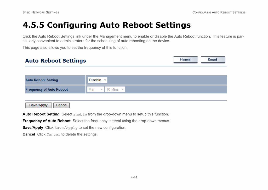
4.5.5 Configuring Auto Reboot SettingsClick the Auto Reboot Settings link under the Management menu to enable or disable the Auto Reboot function. This feature is par-ticularly convenient to administrators for the scheduling of auto rebooting on the device.
This page also allows you to set the frequency of this function.
Auto Reboot Setting Select Enable from the drop-down menu to setup this function.
Frequency of Auto Reboot Select the frequency interval using the drop-down menus.
Save/Apply Click Save/Apply to set the new configuration.
Cancel Click Cancel to delete the settings.
BASIC NETWORK SETTINGS CONFIGURING FIRMWARE UPGRADE
4-45
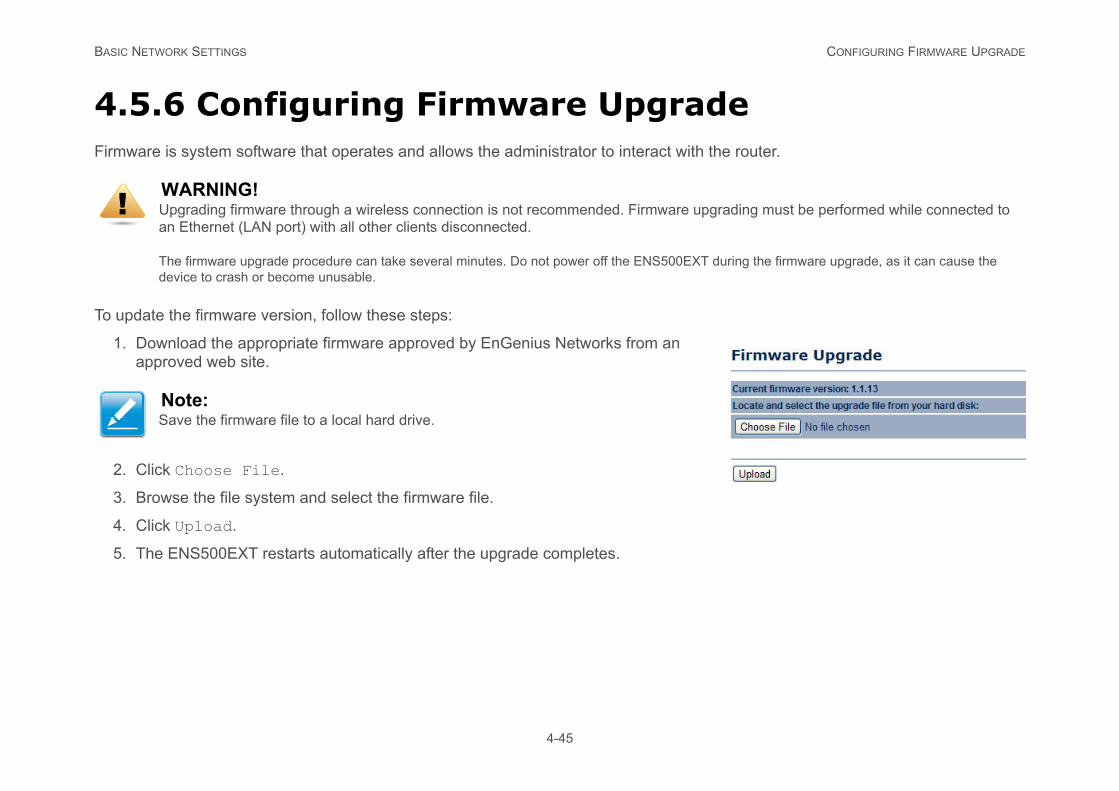
4.5.6 Configuring Firmware UpgradeFirmware is system software that operates and allows the administrator to interact with the router.
To update the firmware version, follow these steps:
1. Download the appropriate firmware approved by EnGenius Networks from an approved web site.
2. Click Choose File.
3. Browse the file system and select the firmware file.
4. Click Upload.
5. The ENS500EXT restarts automatically after the upgrade completes.
WARNING!Upgrading firmware through a wireless connection is not recommended. Firmware upgrading must be performed while connected to an Ethernet (LAN port) with all other clients disconnected.
The firmware upgrade procedure can take several minutes. Do not power off the ENS500EXT during the firmware upgrade, as it can cause the device to crash or become unusable.
Note:Save the firmware file to a local hard drive.
!
BASIC NETWORK SETTINGS CONFIGURING SYSTEM TIME
4-46
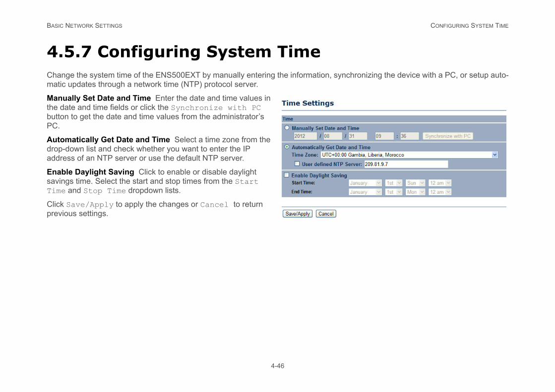
4.5.7 Configuring System TimeChange the system time of the ENS500EXT by manually entering the information, synchronizing the device with a PC, or setup auto-matic updates through a network time (NTP) protocol server.
Manually Set Date and Time Enter the date and time values in the date and time fields or click the Synchronize with PC button to get the date and time values from the administrator’s PC.
Automatically Get Date and Time Select a time zone from the drop-down list and check whether you want to enter the IP address of an NTP server or use the default NTP server.
Enable Daylight Saving Click to enable or disable daylight savings time. Select the start and stop times from the Start Time and Stop Time dropdown lists.
Click Save/Apply to apply the changes or Cancel to return previous settings.
BASIC NETWORK SETTINGS CONFIGURING WI-FI SCHEDULE
ates on a routine basis.
4-47
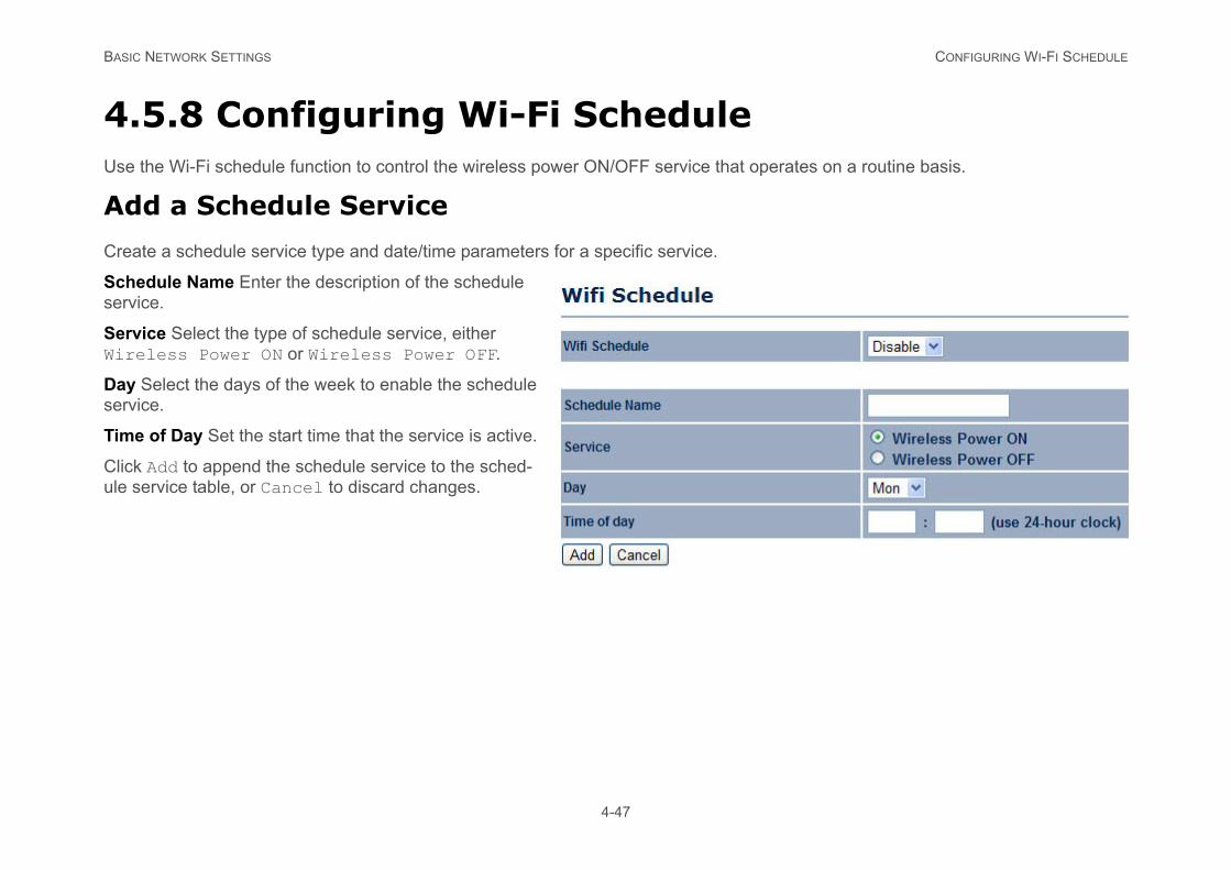
4.5.8 Configuring Wi-Fi ScheduleUse the Wi-Fi schedule function to control the wireless power ON/OFF service that oper
Add a Schedule Service
Create a schedule service type and date/time parameters for a specific service.
Schedule Name Enter the description of the schedule service.
Service Select the type of schedule service, either Wireless Power ON or Wireless Power OFF.
Day Select the days of the week to enable the schedule service.
Time of Day Set the start time that the service is active.
Click Add to append the schedule service to the sched-ule service table, or Cancel to discard changes.
BASIC NETWORK SETTINGS SCHEDULE SERVICES TABLE
ocol (NTP) server. For details on how to con-
es of each service displayed are:
r OFF.
ervices.
4-48
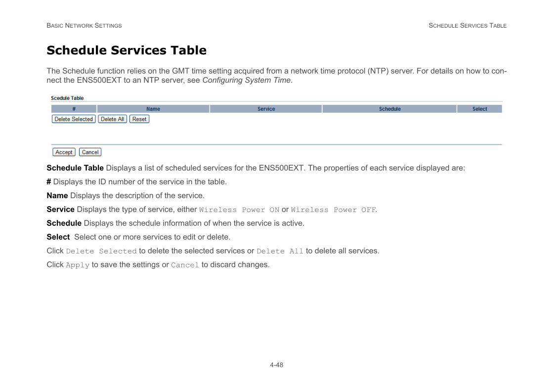
Schedule Services Table
The Schedule function relies on the GMT time setting acquired from a network time protnect the ENS500EXT to an NTP server, see Configuring System Time.
Schedule Table Displays a list of scheduled services for the ENS500EXT. The properti
# Displays the ID number of the service in the table.
Name Displays the description of the service.
Service Displays the type of service, either Wireless Power ON or Wireless Powe
Schedule Displays the schedule information of when the service is active.
Select Select one or more services to edit or delete.
Click Delete Selected to delete the selected services or Delete All to delete all s
Click Apply to save the settings or Cancel to discard changes.
BASIC NETWORK SETTINGS CONFIGURING COMMAND LINE INTERFACE
4-49
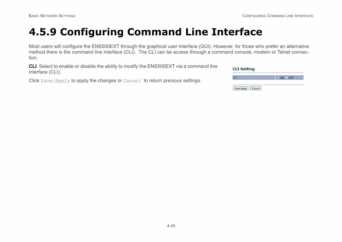
4.5.9 Configuring Command Line InterfaceMost users will configure the ENS500EXT through the graphical user interface (GUI). However, for those who prefer an alternative method there is the command line interface (CLI). The CLI can be access through a command console, modem or Telnet connec-tion.
CLI Select to enable or disable the ability to modify the ENS500EXT via a command line interface (CLI).
Click Save/Apply to apply the changes or Cancel to return previous settings.
BASIC NETWORK SETTINGS CONFIGURING LOGGING
4-50
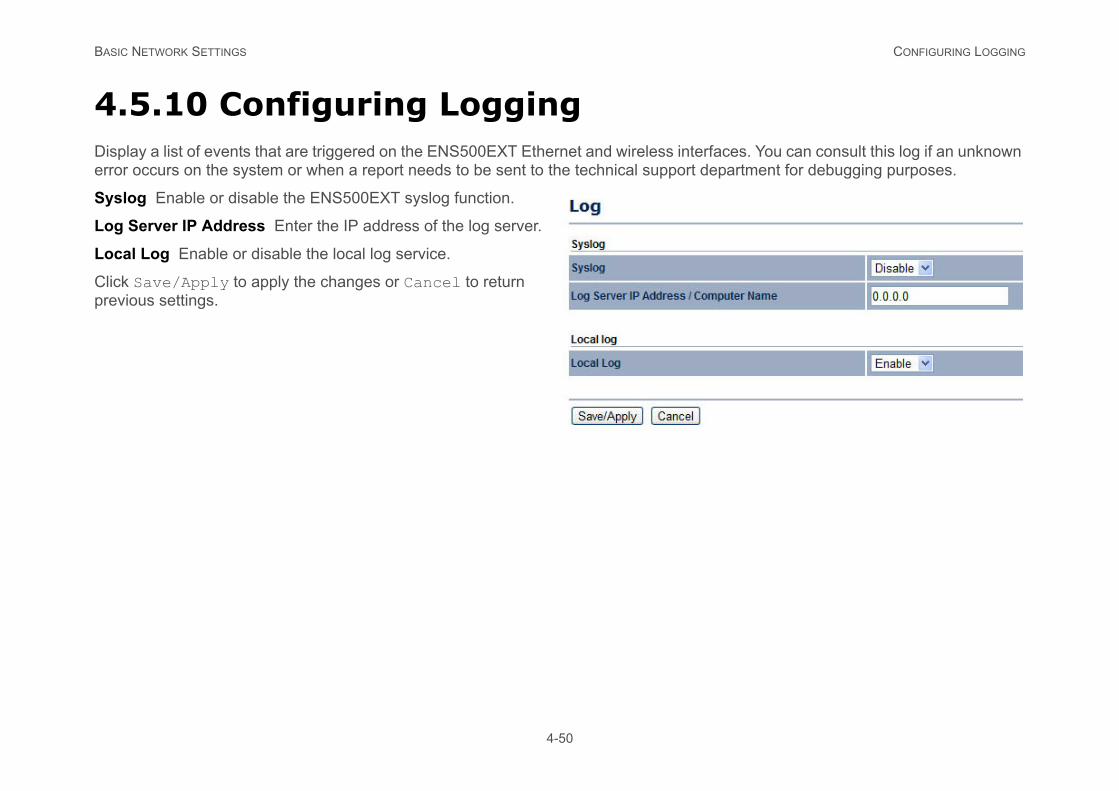
4.5.10 Configuring LoggingDisplay a list of events that are triggered on the ENS500EXT Ethernet and wireless interfaces. You can consult this log if an unknown error occurs on the system or when a report needs to be sent to the technical support department for debugging purposes.
Syslog Enable or disable the ENS500EXT syslog function.
Log Server IP Address Enter the IP address of the log server.
Local Log Enable or disable the local log service.
Click Save/Apply to apply the changes or Cancel to return previous settings.
BASIC NETWORK SETTINGS CONFIGURING DIAGNOSTICS
4-51
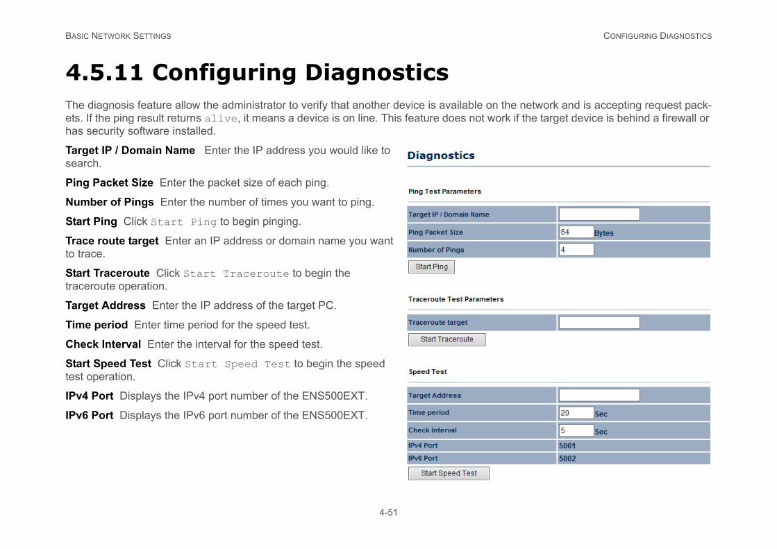
4.5.11 Configuring DiagnosticsThe diagnosis feature allow the administrator to verify that another device is available on the network and is accepting request pack-ets. If the ping result returns alive, it means a device is on line. This feature does not work if the target device is behind a firewall or has security software installed.
Target IP / Domain Name Enter the IP address you would like to search.
Ping Packet Size Enter the packet size of each ping.
Number of Pings Enter the number of times you want to ping.
Start Ping Click Start Ping to begin pinging.
Trace route target Enter an IP address or domain name you want to trace.
Start Traceroute Click Start Traceroute to begin the traceroute operation.
Target Address Enter the IP address of the target PC.
Time period Enter time period for the speed test.
Check Interval Enter the interval for the speed test.
Start Speed Test Click Start Speed Test to begin the speed test operation.
IPv4 Port Displays the IPv4 port number of the ENS500EXT.
IPv6 Port Displays the IPv6 port number of the ENS500EXT.
BASIC NETWORK SETTINGS VIEWING DEVICE DISCOVERY
4-52
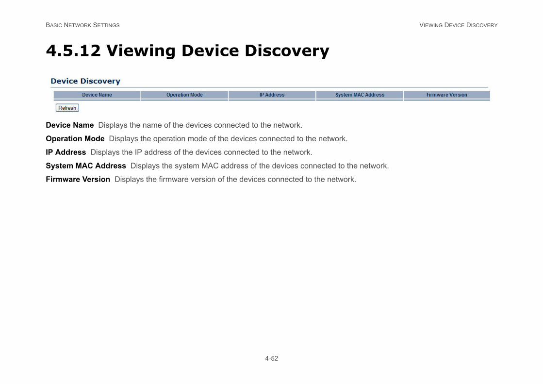
4.5.12 Viewing Device Discovery
Device Name Displays the name of the devices connected to the network.
Operation Mode Displays the operation mode of the devices connected to the network.
IP Address Displays the IP address of the devices connected to the network.
System MAC Address Displays the system MAC address of the devices connected to the network.
Firmware Version Displays the firmware version of the devices connected to the network.
BASIC NETWORK SETTINGS CONFIGURE DENIAL OF SERVICE PROTECTION
4-53
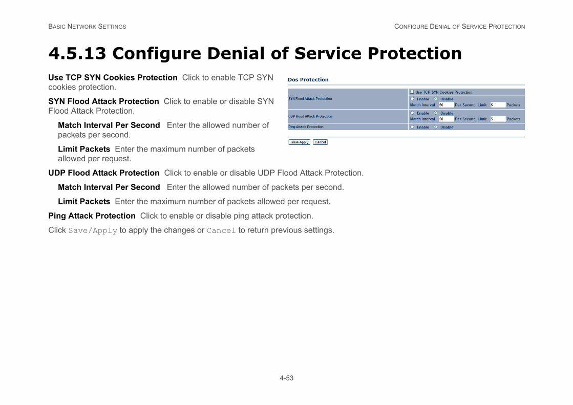
4.5.13 Configure Denial of Service ProtectionUse TCP SYN Cookies Protection Click to enable TCP SYN cookies protection.
SYN Flood Attack Protection Click to enable or disable SYN Flood Attack Protection.
Match Interval Per Second Enter the allowed number of packets per second.
Limit Packets Enter the maximum number of packets allowed per request.
UDP Flood Attack Protection Click to enable or disable UDP Flood Attack Protection.
Match Interval Per Second Enter the allowed number of packets per second.
Limit Packets Enter the maximum number of packets allowed per request.
Ping Attack Protection Click to enable or disable ping attack protection.
Click Save/Apply to apply the changes or Cancel to return previous settings.
BASIC NETWORK SETTINGS LOGGING OUT
4-54
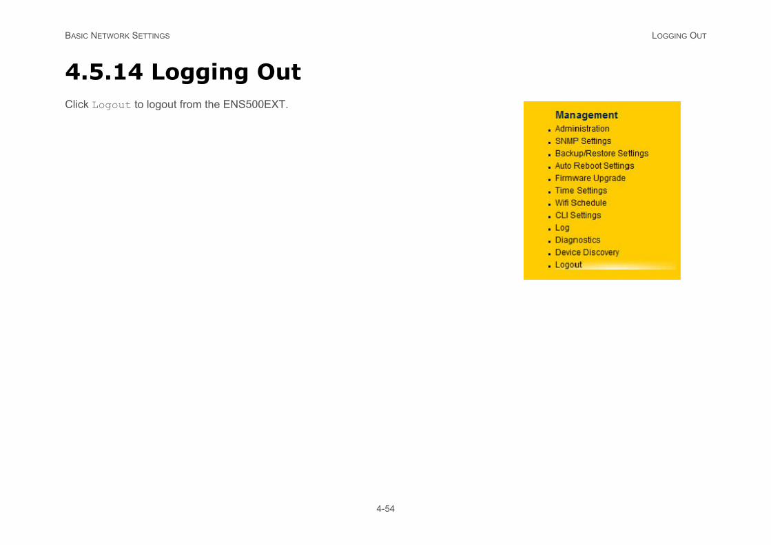
4.5.14 Logging OutClick Logout to logout from the ENS500EXT.
APPENDIX A FEDERAL COMMUNICATION COMMISSION INTERFERENCE STATEMENT
n Interference
device, pursuant to Part 15 of the FCC ference in a residential installation. This nd used in accordance with the instructions, ee that interference will not occur in a partic- reception, which can be determined by turn- one of the following measures:
ceiver is connected.
g two conditions: (1) This device may not cluding interference that may cause unde-
pliance could void the user's authority to oper-
A-1
Appendix A
Federal Communication CommissioStatement
This equipment has been tested and found to comply with the limits for a Class B digitalRules. These limits are designed to provide reasonable protection against harmful interequipment generates uses and can radiate radio frequency energy and, if not installed amay cause harmful interference to radio communications. However, there is no guarantular installation. If this equipment does cause harmful interference to radio or televisioning the equipment off and on, the user is encouraged to try to correct the interference by
Reorient or relocate the receiving antenna.
Increase the separation between the equipment and receiver.
Connect the equipment into an outlet on a circuit different from that to which the re
Consult the dealer or an experienced radio/TV technician for help.
This device complies with Part 15 of the FCC Rules. Operation is subject to the followincause harmful interference, and (2) this device must accept any interference received, insired operation.
FCC Radiation Exposure Statement
WARNING!Any changes or modifications not expressly approved by the party responsible for comate this equipment.
!

APPENDIX A FEDERAL COMMUNICATION COMMISSION INTERFERENCE STATEMENT
ed environment.nment, under 47 CFR 2.1093 paragraph (d)(2).nna or transmitter.
A-2
Important:This equipment complies with FCC radiation exposure limits set forth for an uncontrollThis device complies with FCC RF Exposure limits set forth for an uncontrolled enviroThis transmitter must not be co-located or operating in conjunction with any other ante

APPENDIX B INDUSTRY CANADA STATEMENT
B-1
Appendix B
Industry Canada Statement
This device complies with RSS-210 of the Industry Canada Rules. Operation is subject to the following two conditions: (1) This device may not cause harmful interference, and (2) this device must accept any interference received, including interference that may cause undesired operation.
Ce dispositif est conforme à la norme CNR-210 d'Industrie Canada applicable aux appareils radio exempts de licence. Son fonc-tionnement est sujet aux deux conditions suivantes: (1) le dispositif ne doit pas produire de brouillage préjudiciable, et (2) ce disposi-tif doit accepter tout brouillage reçu, y compris un brouillage susceptible de provoquer un fonctionnement indésirable.
Important:Radiation Exposure Statement: This equipment complies with IC radiation exposure limits set forth for an uncontrolled environment. This equipment should be installed and operated with minimum distance 20cm between the radiator & your body.
Déclaration d'exposition aux radiations: Cet équipement est conforme aux limites d'exposition aux rayonnements IC établies pour un environnement non contrôlé. Cet équipement doit être installé et utilisé avec un minimum de 20 cm de distance entre la source de rayonnement et votre corps.

APPENDIX C WORLDWIDE TECHNICAL SUPPORT
SERVICE INFORMATION
www.engeniuscanada.com
Toll Free: (+1) 888-397-2788Local: (+1) 905-940-8181
Monday - Friday9:00AM to 5:30PM EST (GMT-5)
www.engeniustech.com
Toll Free: (+1) 888-735-7888Local: (+1) 714-432-8668
Monday - Friday8:00 AM to 4:30 PM PST (GMT-8)
C-1
Appendix C
WorldWide Technical Support
REGION/COUNTRY OF PURCHASE SERVICE CENTRE
Canada
CANADA web site
contact numbers
hours of operation
USA
LOS ANGELES, USA web site
contact numbers
hours of operation
APPENDIX C WORLDWIDE TECHNICAL SUPPORT
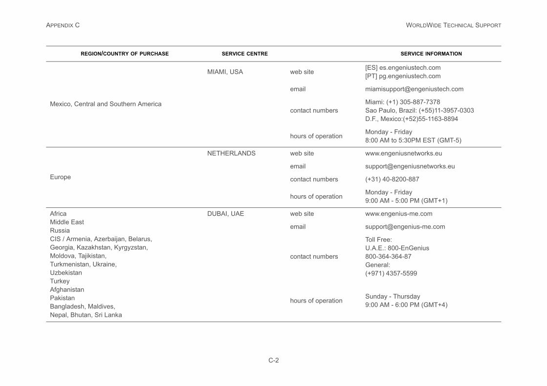
[ES] es.engeniustech.com[PT] pg.engeniustech.com
Miami: (+1) 305-887-7378Sao Paulo, Brazil: (+55)11-3957-0303D.F., Mexico:(+52)55-1163-8894
Monday - Friday8:00 AM to 5:30PM EST (GMT-5)
www.engeniusnetworks.eu
(+31) 40-8200-887
Monday - Friday9:00 AM - 5:00 PM (GMT+1)
www.engenius-me.com
Toll Free:U.A.E.: 800-EnGenius800-364-364-87General:(+971) 4357-5599
Sunday - Thursday9:00 AM - 6:00 PM (GMT+4)
SERVICE INFORMATION
C-2
Mexico, Central and Southern America
MIAMI, USA web site
contact numbers
hours of operation
Europe
NETHERLANDS web site
contact numbers
hours of operation
AfricaMiddle EastRussiaCIS / Armenia, Azerbaijan, Belarus,Georgia, Kazakhstan, Kyrgyzstan,Moldova, Tajikistan,Turkmenistan, Ukraine,UzbekistanTurkeyAfghanistanPakistanBangladesh, Maldives,Nepal, Bhutan, Sri Lanka
DUBAI, UAE web site
contact numbers
hours of operation
REGION/COUNTRY OF PURCHASE SERVICE CENTRE
APPENDIX C WORLDWIDE TECHNICAL SUPPORT
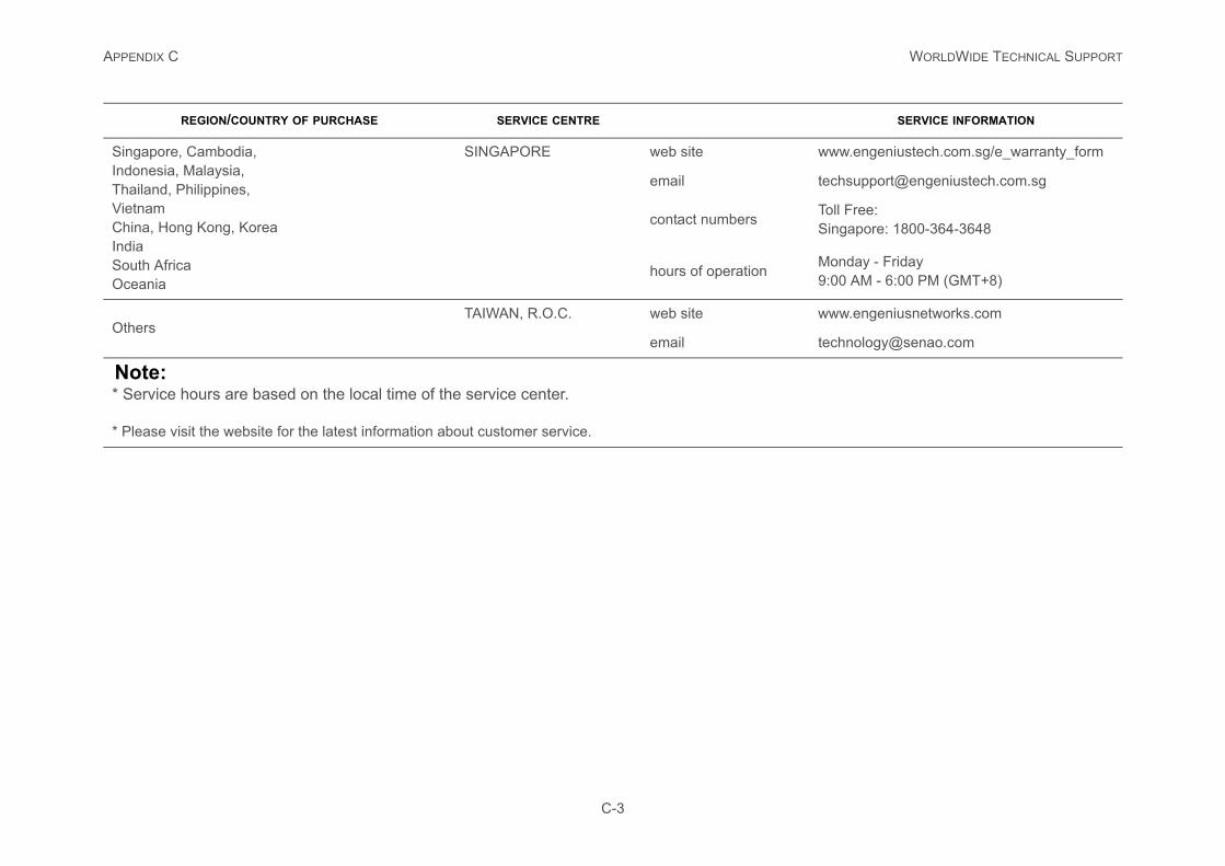
www.engeniustech.com.sg/e_warranty_form
Toll Free:Singapore: 1800-364-3648
Monday - Friday9:00 AM - 6:00 PM (GMT+8)
www.engeniusnetworks.com
SERVICE INFORMATION
C-3
Singapore, Cambodia,Indonesia, Malaysia,Thailand, Philippines,VietnamChina, Hong Kong, KoreaIndiaSouth AfricaOceania
SINGAPORE web site
contact numbers
hours of operation
OthersTAIWAN, R.O.C. web site
Note:* Service hours are based on the local time of the service center.
* Please visit the website for the latest information about customer service.
REGION/COUNTRY OF PURCHASE SERVICE CENTRE