Embed Size (px)
Citation preview

WIRED REMOTE CONTROLLER
(Optional parts)
MODEL NAME :UTY-RVNMUTY-RVNYN
DTR_OP005E_022012.12.12
For Zone Controller functions using this remote controller, refer to "ZONE CONTROL SYSTEM (DTR_OP006E)".

- (OP005 - 01) -
WIR
ED R
EMO
TE
CONT
ROLL
ER
WIR
ED R
EMO
TE
CONT
ROLL
ER
FEATURES11 MODEL��
UTY-RVNM, UTY-RVNYNLarge and full-dot liquid crystal screen ●Screen with backlight can be seen even in the dark ●Wide and large keys easy to press, user-intuitive arrow key ●
Mode
Menu
Cool
Monitor
Set temp. Fan
High° F80
Mo 10:00AM
Icon check:
Temperature unit [°C] Temperature unit [°F]
FEATURES��Group & Individual Control�z
Up to 16 indoor units can be simultaneously controlled. ●Controller is two installation possibility in one indoor unit. ●And controller up to two installation possibility per group control.
User-friendly operation�z
Large backlight LED screen ●Large easy-to-see operation panel ●Multiple Language Supporting ●(English, German, French, Spanish, Russian, Portuguese, Italian, Greek, and Turkish)

- (OP005 - 02) -
WIR
ED R
EMO
TE
CONT
ROLL
ER
WIR
ED R
EMO
TE
CONT
ROLL
ER
MAIN FUNCTIONS��Auto off timer�z
The indoor unit automatically turns ●off after a set time has passed.The time interval for which auto off ●works can be set.
Ex) At interval time hour (17:00 to 24:00) to prevent forgetting to turn off
Set interval time hour (17:00 to 24:00)
Set off time (30 to 240 minutes)
17:00 24:00
ON Auto OFF
OFF
Set temperature auto return�z
The setting temperature automatically ●returns to the previous setting temperature.The time range in which the set ●temperature can be changed is 10 to 120 minutes.
Setting temp.Cooling operation
2422
Set temperature change Auto return
11:40 13:40Time
Settable time range10 to 120 minutes
Setting temp.Heating operation
Set temperature change Auto return
11:40 13:40Time
Settable time range10 to 120 minutes
(°C)7672
(°F)
2523
(°C)7874
(°F)
Set temperature upper and lower limit setting�z
The set temperature range can be ●set for each operation mode.(Cooling / Heating / Auto)
Original temp.setting range
Lower limitsetting
During Cooling30
25
18Original temp.setting range
Upper limitsetting
During Heating(°C)88
78
64
(°F)30
25
16
(°C)88
78
60
(°F)

- (OP005 - 03) -
WIR
ED R
EMO
TE
CONT
ROLL
ER
WIR
ED R
EMO
TE
CONT
ROLL
ER
Weekly timer function�z
Not only time setting On/Off, but also setting of the operation mode and set temperature can be ●set by Weekly timer function. Two types of setting: Weekly 1 and Weekly 2 for summer and winter are possible.
Weekly 1
Set T
emp.
Time
80
687072747678
26(°F) (°C)
202122232425
Set T
emp.
80
687072747678
26(°F) (°C)
202122232425
10:00
22°C
12:00 14:00 17:00 20:00 23:59
Setting menu in remote controller
On
Off
Weekly 2
Time10:00 12:00 14:00 17:00 20:00 23:59
Setting menu in remote controller
On
Off
Weekly 1
Set T
emp.
Time
80
687072747678
26(°F) (°C)
202122232425
Set T
emp.
80
687072747678
26(°F) (°C)
202122232425
10:00
22°C
12:00 14:00 17:00 20:00 23:59
Setting menu in remote controller
On
Off
Weekly 2
Time10:00 12:00 14:00 17:00 20:00 23:59
Setting menu in remote controller
On
Off
Child lock�z
This function locks all control. ●
Part lock�z
This function locks the setting of functions other ●than Mode, Set temp., Fan.
Management (Pass word)�zUnwanted functions can be restricted. ●Password is necessary to operate. ●
Functions with this mark are restricted.
- (OP005 - 04) -
WIR
ED R
EMO
TE
CONT
ROLL
ER
WIR
ED R
EMO
TE
CONT
ROLL
ER
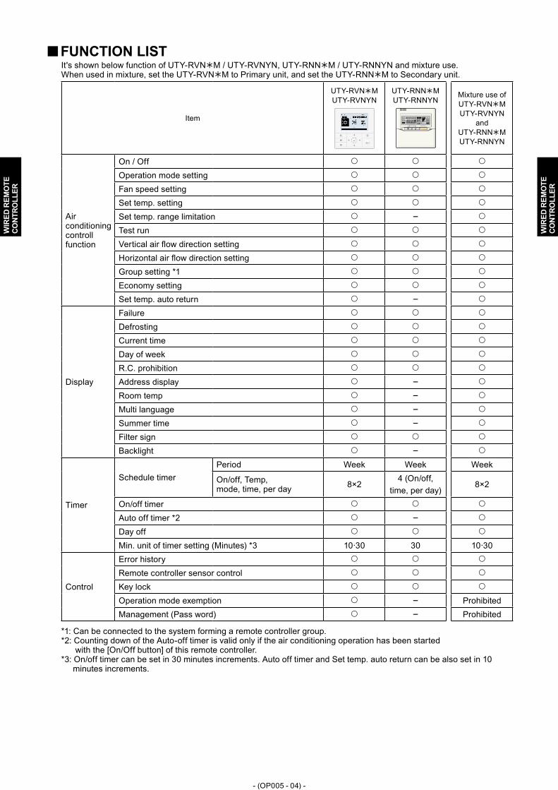
FUNCTION LIST��It's shown below function of UTY-RVNM / UTY-RVNYN, UTY-RNNM / UTY-RNNYN and mixture use.When used in mixture, set the UTY-RVNM to Primary unit, and set the UTY-RNNM to Secondary unit.
Item
UTY-RVNM UTY-RVNYN
UTY-RNNM UTY-RNNYN
Mixture use of UTY-RVNM UTY-RVNYN
and UTY-RNNM UTY-RNNYN
Airconditioning controll function
On / Off
Operation mode setting
Fan speed setting
Set temp. setting
Set temp. range limitation -
Test run
Vertical air flow direction setting
Horizontal air flow direction setting
Group setting *1
Economy setting
Set temp. auto return -
Display
Failure
Defrosting
Current time
Day of week
R.C. prohibition
Address display -
Room temp -
Multi language -
Summer time -
Filter sign
Backlight -
Timer
Schedule timerPeriod Week Week Week
On/off, Temp, mode, time, per day 8×2
4 (On/off,time, per day)
8×2
On/off timer
Auto off timer *2 -
Day off
Min. unit of timer setting (Minutes) *3 10·30 30 10·30
Control
Error history
Remote controller sensor control
Key lock
Operation mode exemption - ProhibitedManagement (Pass word) - Prohibited
*1: Can be connected to the system forming a remote controller group. *2: Counting down of the Auto-off timer is valid only if the air conditioning operation has been started with the [On/Off button] of this remote controller.*3: On/off timer can be set in 30 minutes increments. Auto off timer and Set temp. auto return can be also set in 10 minutes increments.
- (OP005 - 05) -
WIR
ED R
EMO
TE
CONT
ROLL
ER
WIR
ED R
EMO
TE
CONT
ROLL
ER
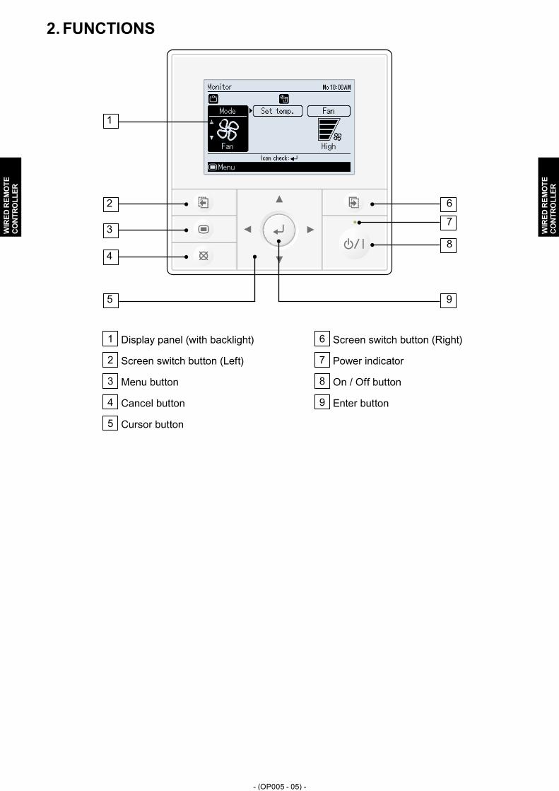
FUNCTIONS21
1
2 6
8
73
4
5 9
1 Display panel (with backlight)
2 Screen switch button (Left)
3 Menu button
4 Cancel button
5 Cursor button
6 Screen switch button (Right)
7 Power indicator
8 On / Off button
9 Enter button

- (OP005 - 06) -
WIR
ED R
EMO
TE
CONT
ROLL
ER
WIR
ED R
EMO
TE
CONT
ROLL
ER
SPECIFICATIONS31 SPECIFICATIONS��
Dimensions [H x W x D]: mm (in.) 120 (4-23/32) x 120 (4-23/32) x 21.3 (27/32)
Weight: g (oz.) 220 (7.8)
WIRING SPECIFICATIONS��Use Cable size Wire type Remarks
Remote controller cable
0.33 mm2
( 22AWG ) Polar 3 coreUTY-RVNM Use sheathed PVC cable.
UTY-RVNYNUse shielded cable (field supplied) inaccordance with the regional cable standard.

- (OP005 - 07) -
WIR
ED R
EMO
TE
CONT
ROLL
ER
WIR
ED R
EMO
TE
CONT
ROLL
ER
DIMENSIONS41
120 (4-23/32)
120
(4-2
3/32
)
21.3(27/32)
30(1-3/16)
45.3
(1-2
5/32
)
12.5
(1/2
)
4.5
(3/1
6)
4.5
(3/1
6)
15.3
(19/
32)
63.5
(2-1
/2)
83.5
(3-9
/32)
23(29/32)
9 (11/32)
4.5 (3/16)
33.5(1-5/16)
Front View Side View Rear View
Unit : mm (in.)
- (OP005 - 08) -
WIR
ED R
EMO
TE
CONT
ROLL
ER
WIR
ED R
EMO
TE
CONT
ROLL
ER
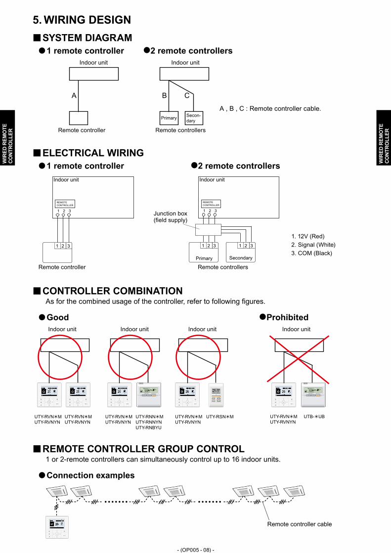
WIRING DESIGN51 SYSTEM DIAGRAM��1 remote controller �z z2 remote controllers
Primary Secon-dary
A B C
Indoor unit Indoor unit
Remote controller Remote controllers
A , B , C : Remote controller cable.
ELECTRICAL WIRING��1 remote controller �z z2 remote controllers
Indoor unit
REMOTECONTROLLER
1 2 3
1 2 3
Primary Secondary
Indoor unit
1 2 3
1 2 3 1 2 3
REMOTECONTROLLER
Remote controller Remote controllers
1. 12V (Red)2. Signal (White)3. COM (Black)
Junction box (field supply)
CONTROLLER COMBINATION��As for the combined usage of the controller, refer to following figures.
Good �z zProhibited
UTY-RVNMUTY-RVNYN
UTY-RNNMUTY-RNNYNUTY-RNBYUUTB-UD
UTY-RVNMUTY-RVNYN
UTY-RSNM UTY-RVNMUTY-RVNYN
UTB-UBUTY-RVNMUTY-RVNYN
UTY-RVNMUTY-RVNYN
SET TEMP. START/STOP SET TEMP. START/STOP
Indoor unit Indoor unit Indoor unit Indoor unit
REMOTE CONTROLLER GROUP CONTROL��1 or 2-remote controllers can simultaneously control up to 16 indoor units.
Connection examples�z
Remote controller cable

- (OP005 - 09) -
WIR
ED R
EMO
TE
CONT
ROLL
ER
WIR
ED R
EMO
TE
CONT
ROLL
ER
INSTALLATION61
1) Installation space.
220 (8-21/32) ormore*
Unit : mm (in.)
30 (1-3/16)or more
30 (1-3/16)or more
30 (1-3/16)or more
* Please secure enough space where a flat screwdriver to take off a case can be inserted.
2) Processing of the remote controller cable.
8(5/16)
8 (5/16)8 (5/16)
30 (1-3/16)
45 (1-25/32)
55 (2-5/32)
Unit : mm (in.)
1. 12V (Red)2. Signal (White)3. COM (Black)
For UTY-RVNYNFix the near end of the Tube with the cable tie (large) firmly. ●
Do not fix the functional earthing wire with the cable tie (large).
Connect the functional earthing wire of remote controller and the remote controller cable, ●and perform the insulation.
3) Insert the flat-blade screwdriver and remove the front case and rear case by twisting it slightly.

- (OP005 - 10) -
WIR
ED R
EMO
TE
CONT
ROLL
ER
WIR
ED R
EMO
TE
CONT
ROLL
ER
4) Installing the remote controller
A1 When attaching to switch box:(1) Seal the wiring hole of the remote controller cable.(2) Put a remote controller cable through the hole of the rear case.(3) Fix the rear case by securing it with attached screws (2 places).
B1 When attaching to the wall directly:(1) Seal the wiring hole of the remote controller cable.(2) Put a remote controller cable through the back hole of the rear case of the main body.(3) Fix the rear case by securing it with attached screws (2 places).
C1 When routing the cable on-wall:(1) Cut off the cable guide of the front case with using a knife or a nipper.(2) Deburr the edge of the cable guide.
(3) Fix the rear case by securing it with attached screws (2 places).

- (OP005 - 11) -
WIR
ED R
EMO
TE
CONT
ROLL
ER
WIR
ED R
EMO
TE
CONT
ROLL
ER
5) Connect the cable to the terminals on the front case. Fix the cable together with the sheath with the cable tie. Cut off the excess cable tie.
Tightening torqueTerminal screw 0.8 to 1.2N • m (8 to 12 lbf • in)
1. 12V (Red)
2. Signal (White)
3. COM (Black)
Cable tie(small)
Remote controller cable (sheath)
Hole for cable tie
2 mm (3/32 in)GOOD PROHIBITED
To avoid an excessive tension or pressure to the terminal block, fix the remote controller cable with the cable tie properly.
CAUTIONBe careful to avoid breaking the cable by over-tightening the cable tie. ●When connecting the remote controller cables, do not over-tighten the screws. ●
6) Attach the front case.Insert after adjusting upper part of front case. ●When insert the front case, do not pinch the cable. ●
Front case
Good
Click!
No good No good No goodPROHIBITEDGOOD
CAUTIONInsert the upper case firmly. If improperly attached, it will cause the upper case to fall off. ●

- (OP005 - 12) -
WIR
ED R
EMO
TE
CONT
ROLL
ER
WIR
ED R
EMO
TE
CONT
ROLL
ER
FUNCTION SETTING71 SWITCH SETTING7-11
DIP Switch
SW1 Memory backup setting
SW2 Dual remote controller setting
Switch position�z
DIP Switch setting�z
Memory backup setting ●Set to ON to use batteries for the memory backup.If batteries are not used, all of settings stored in memory will be deleted if there is a power failure.
(u...Factory setting)
SW1 Memory backup
u OFF Invalidity
ON Validity
Dual remote controller setting ●Set the remote controller SW2 according to the following table.
(u...Factory setting)
Number of remote controller
Primary unit Secondary unit
SW2 SW2
u 1 (Normal) OFF -
2 (Dual) OFF ON
1 2 31 2 3
1 2 3
Indoor unit
Remote controller cable
Primary unit Secondary unit
Remote controller
Junction box (field supply)

- (OP005 - 13) -
WIR
ED R
EMO
TE
CONT
ROLL
ER
WIR
ED R
EMO
TE
CONT
ROLL
ER
INDOOR UNIT (setting by controller)7-21 Function setting for indoor unit can be done by using the remote controller. As for the "FUNCTION SETTING", refer to the DESIGN & TECHNICAL MANUAL for each product.
1) When [Menu button] is pressed twice while “Monitor” screen is displayed, it switches to the “Submenu” screen. If [Menu button] is pressed while the “Submenu” screen is displayed, the display returns to the “Monitor” screen.
Back: Setting:
Date and timeSubmenu [1/2]
Monitor
ScreenFilter signR.C. sensor controlRoom temp. display
OffOff
Mo 10:00
2) Press the [Screen switch button (Left)] and [Screen switch button (Right)] simultaneously for 5 seconds to switch to “Service” screen.
Back Sett ing:
Service Mo 10:00
Funct ion sett ingError historyI.U.address ver i f icat ionVers ion
Test run
3) Select [Function setting] with pressing the [Cursor button (Up/Down)], and press the [Enter button].
Back: Sett ing:
Service Mo 10:00
Funct ion sett ingError historyI.U.address ver i f icat ionVers ion
Test run
4) Select [R.C. address] of the target indoor unit with pressing the [Cursor button (Up/Down)]. (R.C. Address : Remote Controller Address)
Cancel: OK:
Function sett ing Mo 10:00
R.C. Function Setting address No. No.
00 00 00
Version Error history
5) Select the [Function No.] with pressing the [Cursor button (Left/Right)], and select the Function No. to be set with pressing the [Cursor button (Up/Down)].
Cancel: OK:
Function sett ing Mo 10:00
R.C. Function Setting address No. No.
Version Error history
00 00 00
6) Select the [Setting No.] with pressing the [Cursor button (Left/Right)], and select the Setting No. to be set with pressing the [Cursor button (Up/Down)],and press the [Enter button].
Cancel: OK:
Function sett ing Mo 10:00
R.C. Function Setting address No. No.
Version Error history
00 00 00

- (OP005 - 14) -
WIR
ED R
EMO
TE
CONT
ROLL
ER
WIR
ED R
EMO
TE
CONT
ROLL
ER
REMOTE CONTROLLER7-31
Perform the following operations within 3 minutes after turning on the power.
1) Enter the “Service” screen. When [Menu button] is pressed twice while “Monitor” screen is displayed, it switches to the “Submenu” screen. Press the [Screen switch button (Left)] and [Screen switch button (Right)] simultaneously for 5 seconds to switch to “Service” screen.
Back: Setting:
Date and timeSubmenu [1/2]
Monitor
ScreenFilter signR.C. sensor controlRoom temp. display
OffOff
Mo 10:00
MenuBack: Sett ing:
Service Mo 10:00
Funct ion sett ingError historyI.U.address ver i f icat ionVers ion
Test run
2) Press the [Screen switch button (Left)] and [Enter button] and [Cursor button (Downward)] simultaneously for 5 seconds.
3) Switches to the “R.C. function setting” screen.
Operation mode exemptionThe specified operation mode can be removed from the operation mode menu of the wired remote controller.* This does not mean that the operation mode is exempted from the indoor unit.
Check the operation modes you want to exempt. ●Note :
In the case of dual remote control operation, make the primary unit and the ●secondary unit setting the same. Even if only the primary unit is set, it will not be reflected at the secondary unit.
After setting, always perform operation (operation in other than the exempted ●modes). Since the indoor unit memorizes the last operation, overwriting the memory operation mode is unnecessary.
Set temp. range (Initial)The set temperature range of the wired remote controller can be restricted from the beginning.
Set the set temperature range of each operation mode. ●Note :
In the case of dual remote controller operation, make the primary unit and ●secondary unit settings the same. Even if only the primary unit is set, it is not reflected at the secondary unit.After setting, always perform operation. ●Since the indoor unit memorizes the last operation, overwriting of the memory operation mode is unnecessary.
Room temp. correctionThe value sensed by the temperature sensor listed in the wired remote controller can be corrected.
Set the correction value. ●

- (OP005 - 15) -
WIR
ED R
EMO
TE
CONT
ROLL
ER
WIR
ED R
EMO
TE
CONT
ROLL
ER
ACCESSORY PARTS81
Name and shapeQ'ty Summary
UTY-RVNM UTY-RVNYN
Installation manual
1 1
Instruction book for installation
Operating manual
1 1
Instruction book for operation
Remote controller cable1 -
For connecting the remote controller
Connecting cable
1 1
For connecting the remote controller cable to the wall mounted type and the floor type indoor unit
Screw (M4 × 16 mm) 2 2
For installing the remote controller
Cable tie (Small)1 1
For remote controller and remote controller cable binding
Cable tie (Large)- 1
For remote controller andremote controller cable binding
Tube- 1
To protect wiring
Screw (M4 × 14 mm) 1 1
For installing the remote controller cable to the indoor unit
Cable clamper1 1
For installing the remote controller cable to the indoor unit


