Embed Size (px)
Citation preview
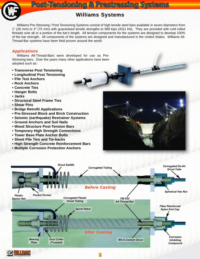
Williams Pre-Stressing / Post Tensioning Systems consist of high tensile steel bars available in seven diameters from1" (26 mm) to 3" (75 mm) with guaranteed tensile strengths to 969 kips (4311 kN). They are provided with cold rolledthreads over all or a portion of the bar's length. All tension components for the systems are designed to develop 100%of the bar strength. All components of the systems are designed and manufactured in the United States. Williams All-Thread-Bar systems have been field proven around the world.
WWilliams Systemsilliams Systems
Before CastingBefore Casting
After CastingAfter Casting
®
FORM ENGINEERING CORP.
• Transverse Post Tensioning• Longitudinal Post Tensioning• Pile Test Anchors• Rock Anchors• Concrete Ties• Hanger Bolts• Jacks• Structural Steel Frame Ties• Shear Pins• Bridge Retrofit Applications• Pre-Stressed Block and Brick Construction• Seismic (earthquake) Restrainer Systems• Ground Anchors and Soil Nails• Wood Structure Post-Tension Bars• Temporary High Strength Connections• Tower Base Plate Anchor Bolts• Sheet Pile Ties and Tie-backs• High Strength Concrete Reinforcement Bars• Multiple Corrosion Protection Anchors
ApplicationsApplicationsWilliams All-Thread-Bars were developed for use as Pre-
Stressing bars. Over the years many other applications have beenadopted such as:
150 KSI 150 KSI All-Thread-BarAll-Thread-Bar
®
FORM ENGINEERING CORP.
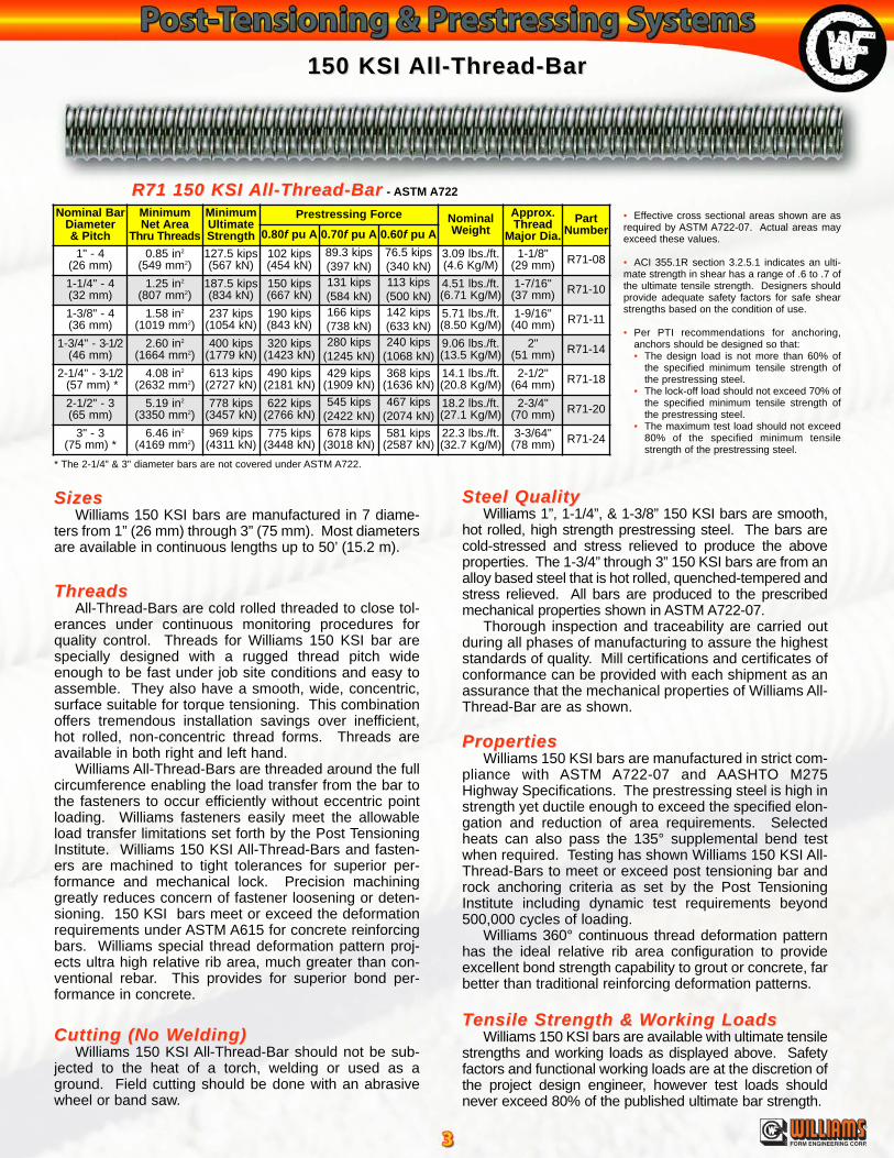
• Effective cross sectional areas shown are asrequired by ASTM A722-07. Actual areas mayexceed these values.
• ACI 355.1R section 3.2.5.1 indicates an ulti-mate strength in shear has a range of .6 to .7 ofthe ultimate tensile strength. Designers shouldprovide adequate safety factors for safe shearstrengths based on the condition of use.
• Per PTI recommendations for anchoring,anchors should be designed so that:• The design load is not more than 60% of
the specified minimum tensile strength ofthe prestressing steel.
• The lock-off load should not exceed 70% ofthe specified minimum tensile strength ofthe prestressing steel.
• The maximum test load should not exceed80% of the specified minimum tensilestrength of the prestressing steel.
R71 150 KSI R71 150 KSI All-Thread-BarAll-Thread-Bar - ASTM A722
Cutting (No WCutting (No Welding)elding)Williams 150 KSI All-Thread-Bar should not be sub-
jected to the heat of a torch, welding or used as aground. Field cutting should be done with an abrasivewheel or band saw.
SizesSizesWilliams 150 KSI bars are manufactured in 7 diame-
ters from 1” (26 mm) through 3” (75 mm). Most diametersare available in continuous lengths up to 50’ (15.2 m).
Steel QualitySteel QualityWilliams 1”, 1-1/4”, & 1-3/8” 150 KSI bars are smooth,
hot rolled, high strength prestressing steel. The bars arecold-stressed and stress relieved to produce the aboveproperties. The 1-3/4” through 3” 150 KSI bars are from analloy based steel that is hot rolled, quenched-tempered andstress relieved. All bars are produced to the prescribedmechanical properties shown in ASTM A722-07.
Thorough inspection and traceability are carried outduring all phases of manufacturing to assure the higheststandards of quality. Mill certifications and certificates ofconformance can be provided with each shipment as anassurance that the mechanical properties of Williams All-Thread-Bar are as shown.
TTensile Strength &ensile Strength & WWorking Loadsorking LoadsWilliams 150 KSI bars are available with ultimate tensile
strengths and working loads as displayed above. Safetyfactors and functional working loads are at the discretion ofthe project design engineer, however test loads shouldnever exceed 80% of the published ultimate bar strength.
PropertiesPropertiesWilliams 150 KSI bars are manufactured in strict com-
pliance with ASTM A722-07 and AASHTO M275Highway Specifications. The prestressing steel is high instrength yet ductile enough to exceed the specified elon-gation and reduction of area requirements. Selectedheats can also pass the 135° supplemental bend testwhen required. Testing has shown Williams 150 KSI All-Thread-Bars to meet or exceed post tensioning bar androck anchoring criteria as set by the Post TensioningInstitute including dynamic test requirements beyond500,000 cycles of loading.
Williams 360° continuous thread deformation patternhas the ideal relative rib area configuration to provideexcellent bond strength capability to grout or concrete, farbetter than traditional reinforcing deformation patterns.
ThreadsThreadsAll-Thread-Bars are cold rolled threaded to close tol-
erances under continuous monitoring procedures forquality control. Threads for Williams 150 KSI bar arespecially designed with a rugged thread pitch wideenough to be fast under job site conditions and easy toassemble. They also have a smooth, wide, concentric,surface suitable for torque tensioning. This combinationoffers tremendous installation savings over inefficient,hot rolled, non-concentric thread forms. Threads areavailable in both right and left hand.
Williams All-Thread-Bars are threaded around the fullcircumference enabling the load transfer from the bar tothe fasteners to occur efficiently without eccentric pointloading. Williams fasteners easily meet the allowableload transfer limitations set forth by the Post TensioningInstitute. Williams 150 KSI All-Thread-Bars and fasten-ers are machined to tight tolerances for superior per-formance and mechanical lock. Precision machininggreatly reduces concern of fastener loosening or deten-sioning. 150 KSI bars meet or exceed the deformationrequirements under ASTM A615 for concrete reinforcingbars. Williams special thread deformation pattern proj-ects ultra high relative rib area, much greater than con-ventional rebar. This provides for superior bond per-formance in concrete.
Nominal BarDiameter& Pitch
MinimumNet Area
Thru Threads
MinimumUltimateStrength
Prestressing Force NominalWeight
Approx.Thread
Major Dia.Part
Number0.80f pu A 0.70f pu A 0.60f pu A1" - 4
(26 mm)0.85 in2
(549 mm2)127.5 kips(567 kN)
102 kips(454 kN)
89.3 kips(397 kN)
76.5 kips(340 kN)
3.09 lbs./ft.(4.6 Kg/M)
1-1/8"(29 mm) R71-08
1-1/4" - 4(32 mm)
1.25 in2
(807 mm2)187.5 kips(834 kN)
150 kips(667 kN)
131 kips(584 kN)
113 kips(500 kN)
4.51 lbs./ft.(6.71 Kg/M)
1-7/16"(37 mm) R71-10
1-3/8" - 4(36 mm)
1.58 in2
(1019 mm2)237 kips
(1054 kN)190 kips(843 kN)
166 kips(738 kN)
142 kips(633 kN)
5.71 lbs./ft.(8.50 Kg/M)
1-9/16"(40 mm) R71-11
1-3/4" - 3-1/2(46 mm)
2.60 in2
(1664 mm2)400 kips
(1779 kN)320 kips
(1423 kN)280 kips
(1245 kN)240 kips
(1068 kN)9.06 lbs./ft.(13.5 Kg/M)
2"(51 mm) R71-14
2-1/4" - 3-1/2(57 mm) *
4.08 in2
(2632 mm2)613 kips
(2727 kN)490 kips
(2181 kN)429 kips
(1909 kN)368 kips
(1636 kN)14.1 lbs./ft.(20.8 Kg/M)
2-1/2"(64 mm) R71-18
2-1/2" - 3(65 mm)
5.19 in2
(3350 mm2)778 kips
(3457 kN)622 kips
(2766 kN)545 kips
(2422 kN)467 kips
(2074 kN)18.2 lbs./ft.(27.1 Kg/M)
2-3/4"(70 mm) R71-20
3" - 3(75 mm) *
6.46 in2
(4169 mm2)969 kips
(4311 kN)775 kips
(3448 kN)678 kips
(3018 kN)581 kips
(2587 kN)22.3 lbs./ft.(32.7 Kg/M)
3-3/64"(78 mm) R71-24
* The 2-1/4” & 3" diameter bars are not covered under ASTM A722.
®
FORM ENGINEERING CORP.
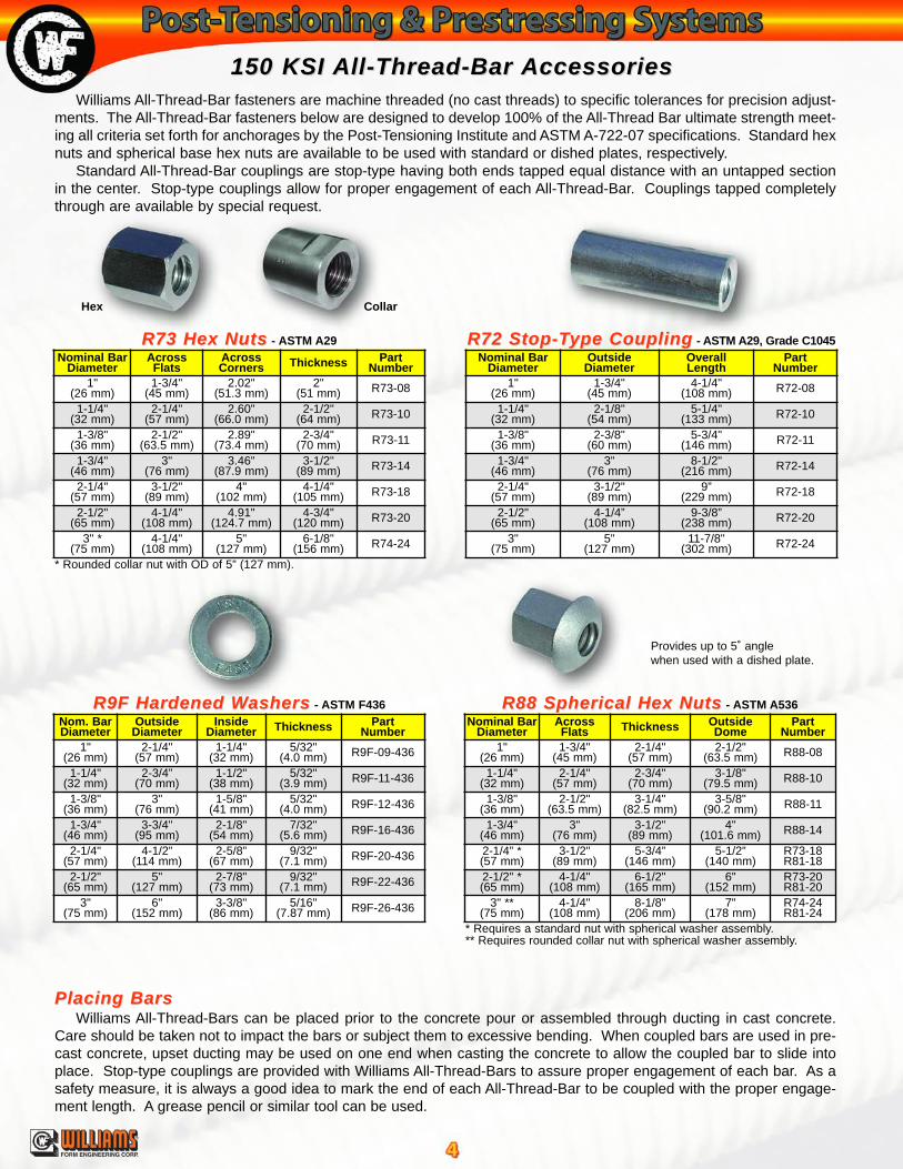
150 KSI 150 KSI All-Thread-Bar All-Thread-Bar AccessoriesAccessoriesWilliams All-Thread-Bar fasteners are machine threaded (no cast threads) to specific tolerances for precision adjust-
ments. The All-Thread-Bar fasteners below are designed to develop 100% of the All-Thread Bar ultimate strength meet-ing all criteria set forth for anchorages by the Post-Tensioning Institute and ASTM A-722-07 specifications. Standard hexnuts and spherical base hex nuts are available to be used with standard or dished plates, respectively.
Standard All-Thread-Bar couplings are stop-type having both ends tapped equal distance with an untapped sectionin the center. Stop-type couplings allow for proper engagement of each All-Thread-Bar. Couplings tapped completelythrough are available by special request.
Placing BarsPlacing BarsWilliams All-Thread-Bars can be placed prior to the concrete pour or assembled through ducting in cast concrete.
Care should be taken not to impact the bars or subject them to excessive bending. When coupled bars are used in pre-cast concrete, upset ducting may be used on one end when casting the concrete to allow the coupled bar to slide intoplace. Stop-type couplings are provided with Williams All-Thread-Bars to assure proper engagement of each bar. As asafety measure, it is always a good idea to mark the end of each All-Thread-Bar to be coupled with the proper engage-ment length. A grease pencil or similar tool can be used.
* Requires a standard nut with spherical washer assembly.** Requires rounded collar nut with spherical washer assembly.
Nominal BarDiameter
OutsideDiameter
OverallLength
PartNumber
1"(26 mm)
1-3/4"(45 mm)
4-1/4"(108 mm) R72-08
1-1/4"(32 mm)
2-1/8"(54 mm)
5-1/4"(133 mm) R72-10
1-3/8"(36 mm)
2-3/8"(60 mm)
5-3/4"(146 mm) R72-11
1-3/4"(46 mm)
3"(76 mm)
8-1/2"(216 mm) R72-14
2-1/4"(57 mm)
3-1/2"(89 mm)
9”(229 mm) R72-18
2-1/2"(65 mm)
4-1/4”(108 mm)
9-3/8”(238 mm) R72-20
3"(75 mm)
5"(127 mm)
11-7/8"(302 mm) R72-24
Nom. BarDiameter
OutsideDiameter
InsideDiameter Thickness Part
Number1"
(26 mm)2-1/4"
(57 mm)1-1/4"
(32 mm)5/32"
(4.0 mm) R9F-09-436
1-1/4"(32 mm)
2-3/4”(70 mm)
1-1/2"(38 mm)
5/32"(3.9 mm) R9F-11-436
1-3/8"(36 mm)
3"(76 mm)
1-5/8"(41 mm)
5/32"(4.0 mm) R9F-12-436
1-3/4"(46 mm)
3-3/4"(95 mm)
2-1/8"(54 mm)
7/32"(5.6 mm) R9F-16-436
2-1/4"(57 mm)
4-1/2”(114 mm)
2-5/8”(67 mm)
9/32"(7.1 mm) R9F-20-436
2-1/2"(65 mm)
5"(127 mm)
2-7/8"(73 mm)
9/32"(7.1 mm) R9F-22-436
3"(75 mm)
6"(152 mm)
3-3/8"(86 mm)
5/16"(7.87 mm) R9F-26-436
Nominal BarDiameter
AcrossFlats Thickness Outside
DomePart
Number1"
(26 mm)1-3/4"
(45 mm)2-1/4"
(57 mm)2-1/2"
(63.5 mm) R88-08
1-1/4"(32 mm)
2-1/4"(57 mm)
2-3/4"(70 mm)
3-1/8"(79.5 mm) R88-10
1-3/8"(36 mm)
2-1/2"(63.5 mm)
3-1/4"(82.5 mm)
3-5/8"(90.2 mm) R88-11
1-3/4"(46 mm)
3"(76 mm)
3-1/2"(89 mm)
4"(101.6 mm) R88-14
2-1/4” *(57 mm)
3-1/2"(89 mm)
5-3/4”(146 mm)
5-1/2”(140 mm)
R73-18R81-18
2-1/2" *(65 mm)
4-1/4"(108 mm)
6-1/2"(165 mm)
6"(152 mm)
R73-20R81-20
3" **(75 mm)
4-1/4"(108 mm)
8-1/8"(206 mm)
7"(178 mm)
R74-24R81-24
* Rounded collar nut with OD of 5” (127 mm).
Provides up to 5˚ anglewhen used with a dished plate.
Nominal BarDiameter
AcrossFlats
AcrossCorners Thickness Part
Number1"
(26 mm)1-3/4"
(45 mm)2.02"
(51.3 mm)2"
(51 mm) R73-08
1-1/4"(32 mm)
2-1/4"(57 mm)
2.60"(66.0 mm)
2-1/2"(64 mm) R73-10
1-3/8"(36 mm)
2-1/2"(63.5 mm)
2.89"(73.4 mm)
2-3/4"(70 mm) R73-11
1-3/4"(46 mm)
3"(76 mm)
3.46"(87.9 mm)
3-1/2"(89 mm) R73-14
2-1/4"(57 mm)
3-1/2"(89 mm)
4"(102 mm)
4-1/4"(105 mm) R73-18
2-1/2"(65 mm)
4-1/4"(108 mm)
4.91"(124.7 mm)
4-3/4"(120 mm) R73-20
3" *(75 mm)
4-1/4"(108 mm)
5"(127 mm)
6-1/8"(156 mm) R74-24
R73 Hex NutsR73 Hex Nuts - ASTM A29 R72 Stop-TR72 Stop-Type Couplingype Coupling - ASTM A29, Grade C1045
R88 Spherical Hex NutsR88 Spherical Hex Nuts - ASTM A536R9F Hardened WR9F Hardened Washersashers - ASTM F436
Hex Collar
®
FORM ENGINEERING CORP.
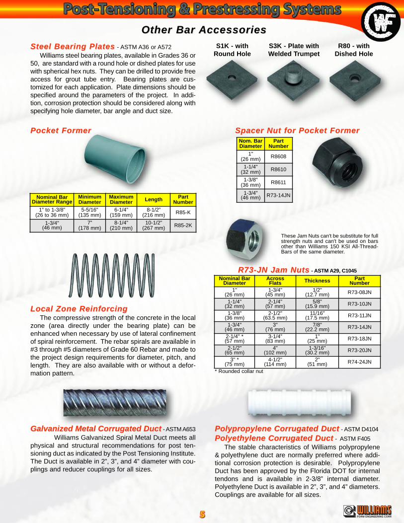
Other Bar Other Bar AccessoriesAccessoriesSteel Bearing PlatesSteel Bearing Plates - ASTM A36 or A572
Williams steel bearing plates, available in Grades 36 or50, are standard with a round hole or dished plates for usewith spherical hex nuts. They can be drilled to provide freeaccess for grout tube entry. Bearing plates are cus-tomized for each application. Plate dimensions should bespecified around the parameters of the project. In addi-tion, corrosion protection should be considered along withspecifying hole diameter, bar angle and duct size.
S1K - withRound Hole
R80 - withDished Hole
Pocket FormerPocket Former
Nominal BarDiameter Range
MinimumDiameter
MaximumDiameter Length Part
Number1” to 1-3/8”
(26 to 36 mm)5-5/16"
(135 mm)6-1/4”
(159 mm)8-1/2”
(216 mm) R85-K
1-3/4"(46 mm)
7”(178 mm)
8-1/4”(210 mm)
10-1/2”(267 mm) R85-2K
Nom. BarDiameter
PartNumber
1"(26 mm) R8608
1-1/4"(32 mm) R8610
1-3/8"(36 mm) R8611
1-3/4"(46 mm) R73-14JN
Spacer Nut for Pocket FormerSpacer Nut for Pocket Former
Galvanized Metal Corrugated DuctGalvanized Metal Corrugated Duct - ASTM A653Williams Galvanized Spiral Metal Duct meets all
physical and structural recommendations for post ten-sioning duct as indicated by the Post Tensioning Institute.The Duct is available in 2”, 3”, and 4” diameter with cou-plings and reducer couplings for all sizes.
Polypropylene Corrugated DuctPolypropylene Corrugated Duct - ASTM D4104
Polyethylene Corrugated DuctPolyethylene Corrugated Duct - ASTM F405The stable characteristics of Williams polypropylene
& polyethylene duct are normally preferred where addi-tional corrosion protection is desirable. PolypropyleneDuct has been approved by the Florida DOT for internaltendons and is available in 2-3/8” internal diameter.Polyethylene Duct is available in 2”, 3”, and 4” diameters.Couplings are available for all sizes.
Local Zone ReinforcingLocal Zone ReinforcingThe compressive strength of the concrete in the local
zone (area directly under the bearing plate) can beenhanced when necessary by use of lateral confinementof spiral reinforcement. The rebar spirals are available in#3 through #5 diameters of Grade 60 Rebar and made tothe project design requirements for diameter, pitch, andlength. They are also available with or without a defor-mation pattern.
S3K - Plate withWelded Trumpet
* Rounded collar nut
Nominal BarDiameter
AcrossFlats Thickness Part
Number1"
(26 mm)1-3/4"
(45 mm)1/2"
(12.7 mm) R73-08JN
1-1/4"(32 mm)
2-1/4"(57 mm)
5/8"(15.9 mm) R73-10JN
1-3/8"(36 mm)
2-1/2"(63.5 mm)
11/16"(17.5 mm) R73-11JN
1-3/4"(46 mm)
3"(76 mm)
7/8"(22.2 mm) R73-14JN
2-1/4" *(57 mm)
3-1/4”(83 mm)
1”(25 mm) R73-18JN
2-1/2"(65 mm)
4"(102 mm)
1-3/16"(30.2 mm) R73-20JN
3" *(75 mm)
4-1/2"(114 mm)
2"(51 mm) R74-24JN
These Jam Nuts can't be substitute for fullstrength nuts and can't be used on barsother than Williams 150 KSI All-Thread-Bars of the same diameter.
R73-JN Jam NutsR73-JN Jam Nuts - ASTM A29, C1045
®
FORM ENGINEERING CORP.
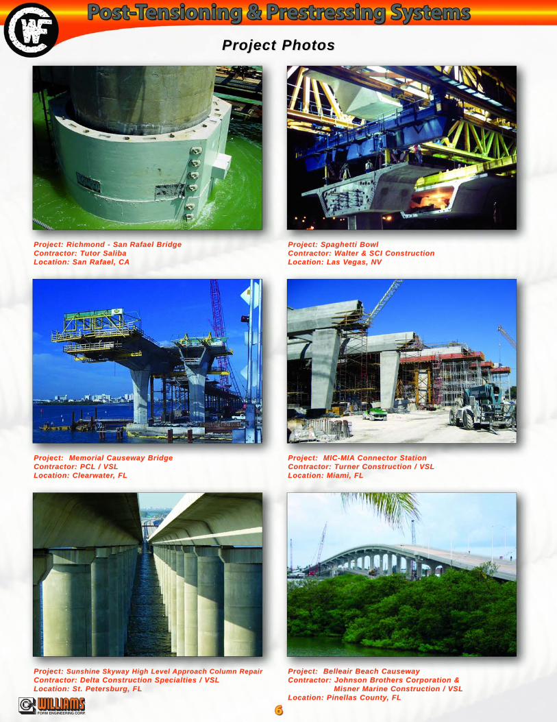
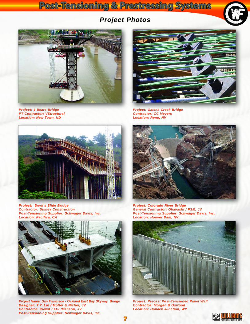
Project PhotosProject Photos
Project: Richmond - SanProject: Richmond - San Rafael BridgeRafael BridgeContractor: TContractor: Tutor Salibautor SalibaLocation: San Rafael, CALocation: San Rafael, CA
Project: Memorial Causeway BridgeProject: Memorial Causeway BridgeContractor: PCLContractor: PCL / VSL/ VSLLocation: ClearwaterLocation: Clearwater, FL, FL
Project: Project: Sunshine Skyway High Level Sunshine Skyway High Level Approach Column RepairApproach Column RepairContractor: Delta Construction Specialties / VSLContractor: Delta Construction Specialties / VSLLocation: St. Petersburg, FLLocation: St. Petersburg, FL
Project: Belleair Beach CausewayProject: Belleair Beach CausewayContractor: Johnson Brothers Corporation &Contractor: Johnson Brothers Corporation &
Misner Marine Construction / VSLMisner Marine Construction / VSLLocation: Pinellas CountyLocation: Pinellas County, FL, FL
Project: Spaghetti BowlProject: Spaghetti BowlContractor: WContractor: Walter &alter & SCI ConstructionSCI ConstructionLocation: Las VLocation: Las Vegas, NVegas, NV
Project: MIC-MIAProject: MIC-MIA Connector StationConnector StationContractor: TContractor: Turner Construction / VSLurner Construction / VSLLocation: Miami, FLLocation: Miami, FL
®
FORM ENGINEERING CORP.
Project: 4 Bears BridgeProject: 4 Bears BridgePT Contractor: VStructuralPT Contractor: VStructuralLocation: New TLocation: New Town, NDown, ND
Project: Devil’Project: Devil’s Slide Bridges Slide BridgeContractor: Disney ConstructionContractor: Disney ConstructionPost-TPost-Tensioning Supplier: Schwager Davis, Inc.ensioning Supplier: Schwager Davis, Inc.Location: Pacifica, CALocation: Pacifica, CA
Project Name: San Francisco - Oakland East Bay Skyway BridgeProject Name: San Francisco - Oakland East Bay Skyway BridgeDesigner: TDesigner: T.Y.Y. Lin / Mof. Lin / Moffet & Nichol, JVfet & Nichol, JVContractor: Kiewit / FCI /Manson, JVContractor: Kiewit / FCI /Manson, JVPost-TPost-Tensioning Supplier: Schwager Davis, Inc.ensioning Supplier: Schwager Davis, Inc.
Project PhotosProject Photos
Project: Precast Post-TProject: Precast Post-Tensioned Panel Wensioned Panel WallallContractor: Morgan &Contractor: Morgan & OswoodOswoodLocation: Hoback Junction, WYLocation: Hoback Junction, WY
Project: Galena Creek BridgeProject: Galena Creek BridgeContractor: CCContractor: CC MeyersMeyersLocation: Reno, NVLocation: Reno, NV
Project: Colorado River BridgeProject: Colorado River BridgeGeneral Contractor: Obayashi / PSM, JVGeneral Contractor: Obayashi / PSM, JVPost-TPost-Tensioning Supplier: Schwager Davis, Inc.ensioning Supplier: Schwager Davis, Inc.Location: Hoover Dam, NVLocation: Hoover Dam, NV
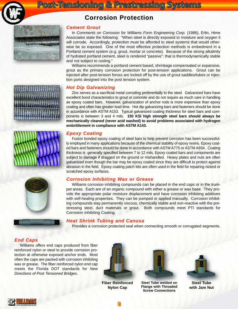
Heat Shrink THeat Shrink Tubing and Canusaubing and CanusaProvides a corrosion protected seal when connecting smooth or corrugated segments.
Hot Dip GalvanizingHot Dip GalvanizingZinc serves as a sacrificial metal corroding preferentially to the steel. Galvanized bars have
excellent bond characteristics to grout or concrete and do not require as much care in handlingas epoxy coated bars. However, galvanization of anchor rods is more expensive than epoxycoating and often has greater lead time. Hot dip galvanizing bars and fasteners should be donein accordance with ASTM A153. Typical galvanized coating thickness for steel bars and com-ponents is between 3 and 4 mils. 150 KSI high strength steel bars should always bemechanically cleaned (never acid washed) to avoid problems associated with hydrogenembrittlement in compliance with ASTM A143.
Epoxy CoatingEpoxy CoatingFusion bonded epoxy coating of steel bars to help prevent corrosion has been successful-
ly employed in many applications because of the chemical stability of epoxy resins. Epoxy coat-ed bars and fasteners should be done in accordance with ASTM A775 or ASTM A934. Coatingthickness is generally specified between 7 to 12 mils. Epoxy coated bars and components aresubject to damage if dragged on the ground or mishandled. Heavy plates and nuts are oftengalvanized even though the bar may be epoxy coated since they are difficult to protect againstabrasion in the field. Epoxy coating patch kits are often used in the field for repairing nicked orscratched epoxy surfaces.
Corrosion Inhibiting WCorrosion Inhibiting Wax or Greaseax or GreaseWilliams corrosion inhibiting compounds can be placed in the end caps or in the trum-
pet areas. Each are of an organic compound with either a grease or wax base. They pro-vide the appropriate polar moisture displacement and have corrosion inhibiting additiveswith self-healing properties. They can be pumped or applied manually. Corrosion inhibit-ing compounds stay permanently viscous, chemically stable and non-reactive with the pre-stressing steel, duct materials or grout. Both compounds meet PTI standards forCorrosion Inhibiting Coating.
Corrosion ProtectionCorrosion ProtectionCement GroutCement Grout
In Comments on Corrosion for Williams Form Engineering Corp. (1986), Erlin, HimeAssociates state the following: “When steel is directly exposed to moisture and oxygen itwill corrode. Accordingly, protection must be afforded to steel systems that would other-wise be so exposed. One of the most effective protection methods is embedment in aPortland cement system (e.g. grout, mortar or concrete). Because of the strong alkalinityof hydrated portland cement, steel is rendered “passive”; that is thermodynamically stableand not subject to rusting.”
Williams recommends a portland cement based, shrinkage compensated or expansive,grout as the primary corrosion protection for post-tension applications. Grout can beinjected after post-tension forces are locked off by the use of grout saddles/tubes or injec-tion ports designed into the post tension system.
Steel Tubewith Jam Nut
Steel Tube welded onFlange with ThreadedScrew Connections
Fiber ReinforcedNylon Cap
®
FORM ENGINEERING CORP.
End CapsEnd CapsWilliams offers end caps produced from fiber
reinforced nylon or steel to provide corrosion pro-tection at otherwise exposed anchor ends. Mostoften the caps are packed with corrosion inhibitingwax or grease. The fiber reinforced nylon end capmeets the Florida DOT standards for NewDirections of Post Tensioned Bridges.
T3PT3P Heavy Duty Plastic Grout THeavy Duty Plastic Grout TubeubeFurnished in product lengths or in rolls.
Grouting Grouting AccessoriesAccessories
Super PlasticizerSuper PlasticizerPlasticizer is available and is used as a water reduc-
er for ease of pumping grout through tubes at lowerwater to cement ratios.
O.D. I.D.3/8”
(9.5 mm)1/4”
(6.4 mm)1/2”
(12.7 mm)3/8”
(9.5 mm)5/8”
(15.9 mm)1/2”
(12.7 mm)3/4”
(19.1 mm)5/8”
(15.9 mm)3/4”*
(19.1 mm)5/8”*
(15.9 mm)
Grout Saddle SystemGrout Saddle SystemComplete with two plastic ties. For 3/4” O.D. corru-
gated tube.
GroutingGroutingGrouting equipment shall be capable of properly mix-
ing a low water to portland cement mix ratio. Equipmentshall be capable of pumping at pressures up to 200 PSI.Standby equipment for flushing must be available.Grouting procedures should always assure the duct isgrouted from the lowest gravitational point and vented tothe highest.
Colloidal Grout PlantColloidal Grout PlantThe heavy duty, high volume Colloidal Grout Plant is
favored for precision post-tension grouting. The unit fea-tures a high speed shear mixer that thoroughly wets eachparticle and discharges the mixed material into a 13 cubicfoot capacity agitating holding tank. A direct coupled pro-gressing cavity pump delivers slurries at a rate of up to 20gpm and pressures of up to 261 psi. The unit easily mixesand pumps slurries of Portland cement, fly ash, bentonite,and lime flour. All controls are conveniently located on theoperator platform for easy one-man control.
PumpPump Type: 31.6 progressing cavityOutput/Pressure: variable up to 20 gpm, 261 psi
Colloidal MixerMix Tank: 13.0 CF with bottom clean outMixing Pump: 2 x 3 x 6 diffuser-type centrifugalHolding Tank: 13.0 CF paddle agitating
Drive PowerAir: 300 CFM, 100 psi
Physical SpecificationsDimensions: 96”L x 60”W x 63”HWeight: 1800-2800 lbs.
Grout Saddle
CorrugatedGrout Tube
De-Air Valve
* Corrugated Grout Tube
®
FORM ENGINEERING CORP.
Intake Valve
BrassFitting
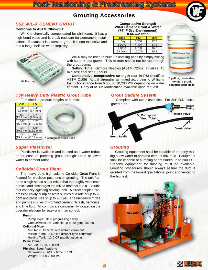
S5Z WIL-X CEMENT GROUTS5Z WIL-X CEMENT GROUTConforms to ASTM C845-76 T
Wil-X is chemically compensated for shrinkage. It has ahigh bond value and is crack resistant for permanent instal-lations. Because it is a cement-grout, it is non-explosive andhas a long shelf life when kept dry.
5 gallon, resealable,moisture proof,
polypropylene pails94 lbs. bag
Compressive StrengthWil-X Cement Grout & Water
(74° F Dry Environment)0.44 w/c ratio
Wil-X may be used to build up leveling pads by simply mixingwith sand or pea gravel. This mixture should not be run throughthe grout pump.
Setting Time: Gilmore Needles (ASTM C266). Initial set 45minutes; final set 10 hours.
Comparative compressive strength test in PSI (modifiedASTM C109) Actual strengths as mixed according to WilliamsInstructions range from 6,000 to 10,200 PSI depending on watercontent. Copy of ASTM Modification available upon request.
Time PSI MPa1 Day 3,200 22.23 Days 4,800 33.17 Days 6,700 46.2
28 Days 10,200 70.3

R71 150 KSI R71 150 KSI All-Thread-Bar TAll-Thread-Bar Torque Torque Tension Chartension ChartAll data based on greased (MolyCoat Gn) threads and surfaces.
T1Z Long Fitting TT1Z Long Fitting Tool ool AdaptersAdaptersFor torquing hex nuts, the deep
socket fits over the bar’s end. Workswith torque wrench or impact gun.Available with a 1-1/2” square drive.
K3F Long Fitting WK3F Long Fitting Wrench rench AdapterAdapterFor applying torque to recessed nuts that are under tension
when using open frame hydraulicjacks. Available in all sizes.
T8Z Manual TT8Z Manual Torque Worque WrenchrenchFor applying torque to the nut. Available for 1” to 1-3/8” dia.
with a 1” square drive for up to 1,000 ft.-lbs. capacity.
T8Z-04 TT8Z-04 Torque Multiplier (4:1)orque Multiplier (4:1)For use with T8Z Torque Wrench.
Available with a 1” squaredrive input and 1-1/2” output for upto 4,000 ft.-lbs. maximum torque.
TTensioningensioning
ft. -
lbs.
Load in Kips
T3Z Hex Knocker WT3Z Hex Knocker WrenchrenchHex Knocker Wrenches
are used for safe hex nutadjustment inside of openframe jacks.
®
FORM ENGINEERING CORP.
TTorque Equipmentorque Equipment
Torque TensioningThe high quality rolled thread of Post-Tensioning Bars can be torque tensioned in limited situations up to 60% of the
bar's ultimate strength. This eliminates the costly and time-consuming process of lifting heavy jacking equipment on andoff with a crane. The entire process takes only minutes by workers already in place and relieves expensive crane equip-ment to be utilized elsewhere on the project. Due to many variables of a torque tension relationship, Williams does notrecommend the torque method ofapplying the load as an accuratesubstitute for direct tensioningwith a hydraulic jack.
Tensioning By JackingTensioning by jacking can be
accomplished with the variouscapacity tensioning jacks shownbelow. Williams T80 Post-Tensioning Jacks are designed tobe especially helpful for recessedsituations, while the T7Z HydraulicTest Jacks are designed for openareas. Jacks are matched withelectric or air pumps. Jacks maybe purchased or rented asrequired. Rental equipment pack-ages include ram on mountedstand, hoses, pull rod, gauges,power unit and knocker wrench fortransferring the load from the jackto the anchor head.
T8Z Hydraulic TT8Z Hydraulic Torque Worque WrenchrenchThe hydraulic torque wrench is used for tensioning
anchors in tight fitting locations where it would be difficultto use an hydraulic jack. The wrench is also recom-mended for use when setting the large diameter Spin-Lock anchors. The torque wrenches are light weight andcan achieve a maximum of 7,400 ft-lbs. All HydraulicTorque Wrenches have 1-1/2” square drive outputs.
MaximumTorque Length Height Weight
5,590 ft./lbs.(773 kg/M)
11.11"(279 mm)
4.49"(114 mm)
16.75 lbs.(7.6 kg)
7,400 ft./lbs.(1,023 kg/M)
10.74"(273 mm)
7"(178 mm)
19 lbs.(11.3 kg)

®
FORM ENGINEERING CORP.
T80 Post-TT80 Post-Tension Hydraulic Jacksension Hydraulic JacksWith the T80 series the enclosed bearing housing contains a geared socket drive to tighten the bolt hex nut during
tensioning. Test jack housing will accommodate up to a 16” deep pocket (The 200 ton accommodates a 14-1/2” pock-
T7Z Open Frame Hydraulic JacksT7Z Open Frame Hydraulic JacksUsed for testing and pre-stressing All-Thread-Bars. Available with up to 5-1/8” center hole. Unit comes with ram,
pump, gauge, hoses, jack stand, high strength coupling, high strength test rod, plate, hex nut and knocker wrench.
RamDirectional
Lever Hose fromBottom Fitting
on Jack to Pump
Nut
HydraulicJack
High StrengthExtension Rod
Base
Hose from Pump toTop Fitting on Jack
JackGauge
Hydraulic Pump(Air or Electric Drive
High StrengthCoupling
Plate
Certification of gauge accuracy available on request prior to shipment only.
Hydraulic JacksHydraulic Jacks
JackCapacity
PumpMethod
RamHeight
BaseSize
RamTravel
MinimumTotal Ram& FrameHeight
MaximumTest RodDiameter
RamArea
Approx.Total Ram& FrameWeight
60 tons(534 kN)
Hand, Air, or ElectricDouble Acting
9-1/2"(241 mm)
GearBox: 8.5" x 20.5"(215 x 520 mm)Nose: 3.63" Dia.
(92 mm Dia.)
5"(127 mm)
33"(838 mm)
2"(51 mm)
12.31 in2
(7,942 mm2)122 lbs.(55 kg)
60 tons(534 kN)
Hand, Air, or ElectricDouble Acting
12-3/4”(324 mm)
6-1/2”(165 mm)
36”(914 mm)
2”(51 mm)
12.73 in2
(8,213 mm2)225 lbs.(102 kG)
100 tons(890 kN)
Air or ElectricDouble Acting
13-1/2"(343 mm)
GearBox: 8.5" x 20.5"(216 x 520 mm)Nose: 4.63" Dia.(118 mm Dia.)
6"(152 mm)
39"(990 mm)
3-1/8"(79 mm)
20.63 in2
(13,310 mm2)270 lbs.(123 kg)
150 tons(1334 kN)
Air or ElectricDouble Acting
12-1/4"(311 mm)
5"(127 mm)
28"(965 mm)
2-1/2"(64 mm)
30.1 in2
(19,419 mm2)243 lbs.(110 kg)
200 tons(1779 kN)
Air or ElectricDouble Acting
16"(406 mm)
Frame:11”x11”x19.75”Nose: 7” Dia.
8"(203 mm)
43"(1097 mm)
4"(102 mm)
40.45 in2
(26,097 mm2)455 lbs.(203 kg)
JackCapacity
PumpMethod
RamHeight
BaseSize
RamTravel
MinimumTotal Ram& FrameHeight
MaximumTest RodDiameter
RamArea
Approx.Total Ram& FrameWeight
10 tons(89 kN)
HandSingle Acting
5-5/16”(135 mm)
3” Diameter(76 mm)
2-1/2”(64 m)
8-3/8”(213 mm)
3/4”(19 mm)
2.12 in2
(1,368 mm2)12 lbs.(5.4 kg)
30 tons(267 kN)
HandSingle Acting
6-1/16”(154 mm)
8" x 8"(203 x 203 mm)
3”(76 mm)
19”(483 mm)
1-1/4”(32 mm)
5.89 in2
(3,800 mm2)80 lbs.(36 kg)
60 tons(534 kN)
Hand, Air, or ElectricDouble Acting
9-1/2"(241 mm)
8" x 8"(203 x 203 mm)
5"(127 mm)
29"(737 mm)
2"(51 mm)
12.31 in2
(7,942 mm2)153 lbs.(69 kg)
60 tons(534 kN)
Hand, Air, or ElectricDouble Acting
12-3/4”(324 mm)
9” x 9”(228 x 228 mm)
6-1/2”(165 mm)
29”(737 mm)
2”(51 mm)
12.73 in2
(8,213 mm2)225 lbs.(102 kg)
100 tons(890 kN)
Air or ElectricDouble Acting
13-1/2”(343 mm)
9” x 9”(228 x 228 mm)
6"(152 mm)
35”(889 mm)
3-1/8”(79 mm)
20.63 in2
(13,310 mm2)270 lbs.(123 kg)
100 tons(890 kN)
Air or ElectricDouble Acting
12-3/8"(314 mm)
9" x 9"(228 x 228 mm)
6"(152 mm)
28"(711 mm)
2"(51 mm)
20.03 in2
(12,923 mm2)192 lbs.(87 kg)
150 tons(1334 kN)
Air or ElectricDouble Acting
12-1/4"(311 mm)
12" x 12"(305 x 305 mm)
5"(127 mm)
32-1/4"(819 mm)
2-1/2"(64 mm)
30.1 in2
(19,419 mm2)350 lbs.(159 kg)
200 tons(1779 kN)
Air or ElectricDouble Acting
16"(406 mm)
12" x 12"(305 x 305 mm)
8"(203 mm)
34"(864 mm)
4"(102 mm)
40.45 in2
(26,097 mm2)518 lbs.(235 kg)
300 tons(2670 kN)
ElectricDouble Acting
27-1/2"(699 mm)
15" Dia.(381 mm)
15"(381 mm)
50-1/2"(1283 mm)
5-3/8"(137 mm)
78.5 in2
(50,645 mm2)1,400 lbs.(635 kg)
400 tons(3558 kN)
ElectricDouble Acting
18-3/4"(476 mm)
15" Dia.(381 mm)
6"(152 mm)
45-3/4"(1162 mm)
4-1/4"(108 mm)
91.5 in2
(59,032 mm2)1,300 lbs.(590 kg)
400 tons(3558 kN)
ElectricDouble Acting
20-3/8”(518 mm)
17” Dia.(432 mm)
8”(203 mm)
49”(1245 mm)
5”(127 mm)
118.2in2
(76,258 mm2)1,500 lbs.(680 kg)
670 Industrial RoadLondon, ON, N5V 1V1Phone: (519) 659-9444
Fax: (519) 659-5880
Laval, P.Q.Phone: (450) 962-2679
Fax: (450) 962-2680
FORM HARDWARE & ROCK BOLT (Canada) LTD.
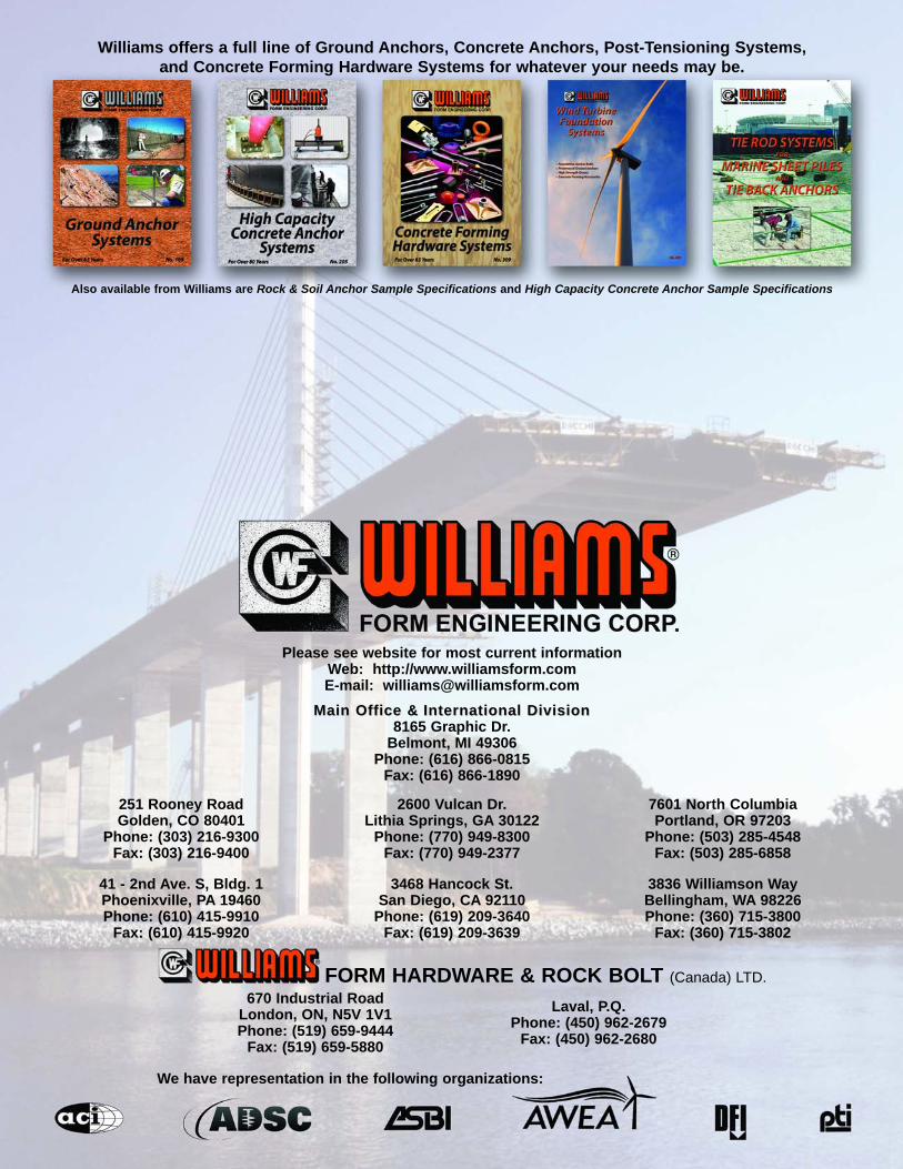
Williams offers a full line of Ground Anchors, Concrete Anchors, Post-Tensioning Systems,and Concrete Forming Hardware Systems for whatever your needs may be.
Also available from Williams are Rock & Soil Anchor Sample Specifications and High Capacity Concrete Anchor Sample Specifications
251 Rooney RoadGolden, CO 80401
Phone: (303) 216-9300Fax: (303) 216-9400
2600 Vulcan Dr.Lithia Springs, GA 30122
Phone: (770) 949-8300Fax: (770) 949-2377
7601 North ColumbiaPortland, OR 97203
Phone: (503) 285-4548Fax: (503) 285-6858
41 - 2nd Ave. S, Bldg. 1Phoenixville, PA 19460Phone: (610) 415-9910
Fax: (610) 415-9920
3468 Hancock St.San Diego, CA 92110
Phone: (619) 209-3640Fax: (619) 209-3639
3836 Williamson WayBellingham, WA 98226Phone: (360) 715-3800
Fax: (360) 715-3802
Please see website for most current informationWeb: http://www.williamsform.comE-mail: [email protected]
Main Office &Main Office & International DivisionInternational Division8165 Graphic Dr.
Belmont, MI 49306Phone: (616) 866-0815
Fax: (616) 866-1890
We have representation in the following organizations: