Embed Size (px)
Citation preview

William Stallings William Stallings Computer Organization and Architectureand Architecture8th Edition
Chapter 3Top Level View of Computer Function and Interconnection
Program Conceptg p• Hardwired systems are inflexible
G l h d d• General purpose hardware can do different tasks, given correct control i lsignals
• Instead of re-wiring, supply a new set of control signals

What is a program?p g• A sequence of steps
h h l l• For each step, an arithmetic or logical operation is done
• For each operation, a different set of control signals is needed
Function of Control Unit• For each operation a unique code is
providedprovided—e.g. ADD, MOVE
• A hardware segment accepts the code and issues the control signals
• We have a computer!We have a computer!

Componentsp• The Control Unit and the Arithmetic and
Logic Unit constitute the Central Logic Unit constitute the Central Processing Unit
d i i d i h• Data and instructions need to get into the system and results out—Input/output
• Temporary storage of code and results is needed—Main memoryy
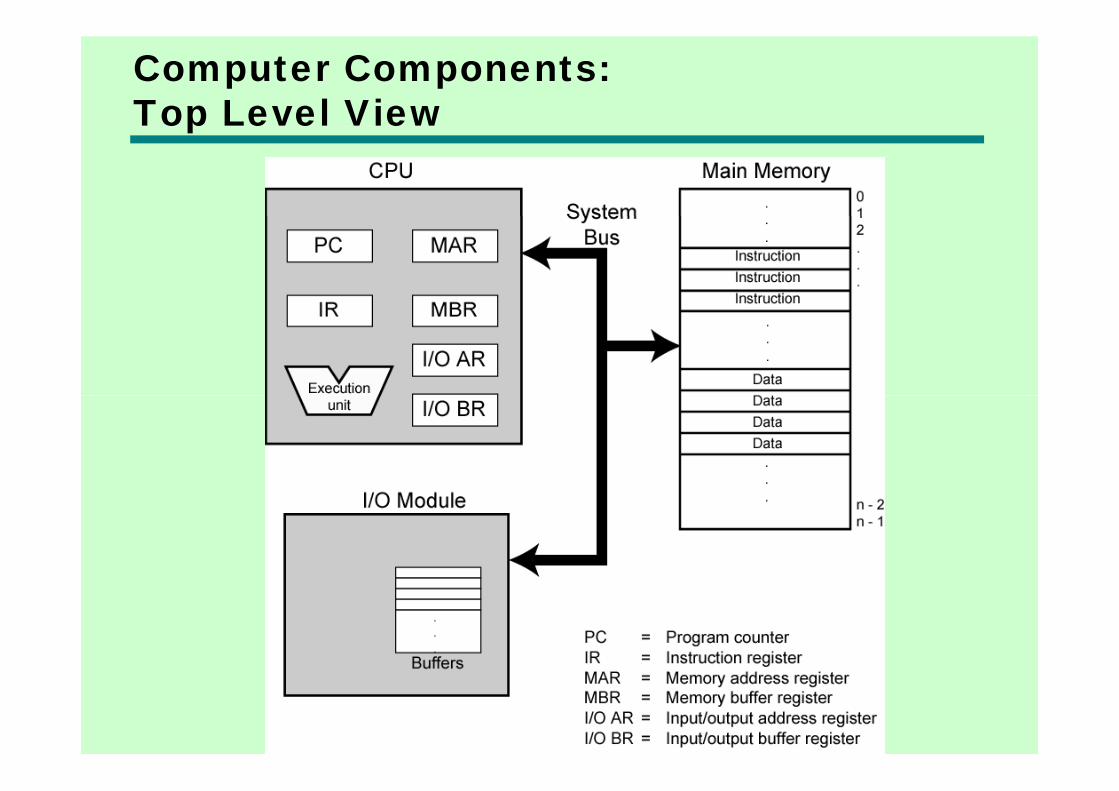
Computer Components:Top Level Viewp

Instruction Cycley• Two steps:
F t h—Fetch—Execute

Fetch Cycley• Program Counter (PC) holds address of
next instruction to fetchnext instruction to fetch• Processor fetches instruction from
l i i d b Cmemory location pointed to by PC• Increment PC
—Unless told otherwise• Instruction loaded into Instruction Instruction loaded into Instruction
Register (IR)• Processor interprets instruction and • Processor interprets instruction and
performs required actions
Execute Cycley• Processor-memory
d t t f b t CPU d i —data transfer between CPU and main memory• Processor I/O
—Data transfer between CPU and I/O module• Data processingp g
—Some arithmetic or logical operation on data• ControlControl
—Alteration of sequence of operations—e g jumpe.g. jump
• Combination of above

Example of Program Executionp g
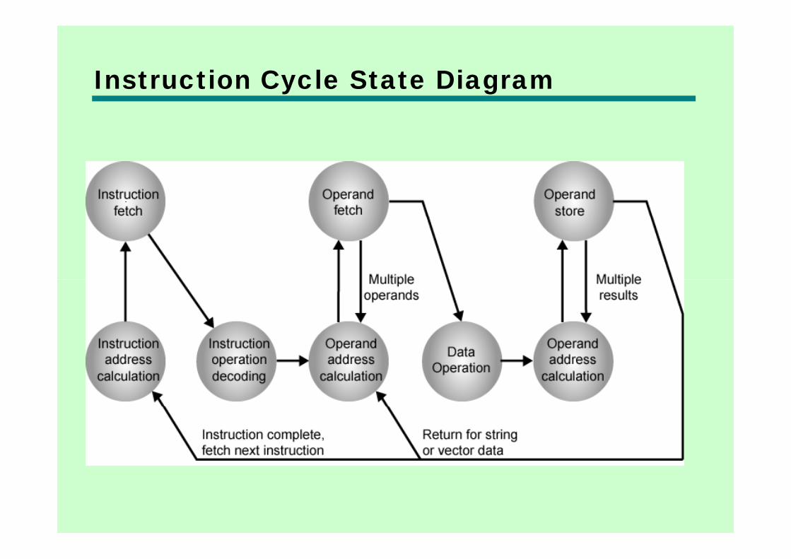
Instruction Cycle State Diagramy g
Interruptsp• Mechanism by which other modules (e.g.
I/O) may interrupt normal sequence of I/O) may interrupt normal sequence of processing
• Program—e.g. overflow, division by zero
• Timer—Generated by internal processor timery p—Used in pre-emptive multi-tasking
• I/OI/O—from I/O controller
• Hardware failure• Hardware failure—e.g. memory parity error

Program Flow Controlg
Interrupt Cyclep y• Added to instruction cycle
h k f• Processor checks for interrupt—Indicated by an interrupt signal
• If no interrupt, fetch next instruction• If interrupt pending:If interrupt pending:
—Suspend execution of current program —Save contextSave context—Set PC to start address of interrupt handler
routine—Process interrupt—Restore context and continue interrupted Restore context and continue interrupted
program

Transfer of Control via Interruptsp
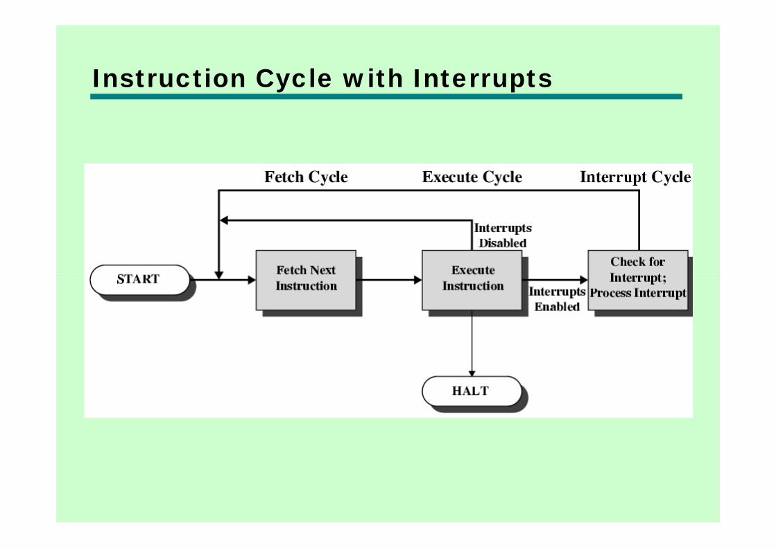
Instruction Cycle with Interruptsy p

Program TimingShort I/O Wait
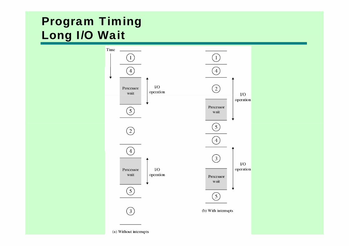
Program TimingLong I/O Waitg

Instruction Cycle (with Interrupts) -State Diagramg

Multiple Interruptsp p• Disable interrupts
P ill i f th i t t hil t —Processor will ignore further interrupts whilst processing one interruptInterrupts remain pending and are checked —Interrupts remain pending and are checked after first interrupt has been processed
—Interrupts handled in sequence as they occur—Interrupts handled in sequence as they occur• Define priorities
L i it i t t b i t t d b —Low priority interrupts can be interrupted by higher priority interruptsWhen higher priority interrupt has been —When higher priority interrupt has been processed, processor returns to previous interruptinterrupt
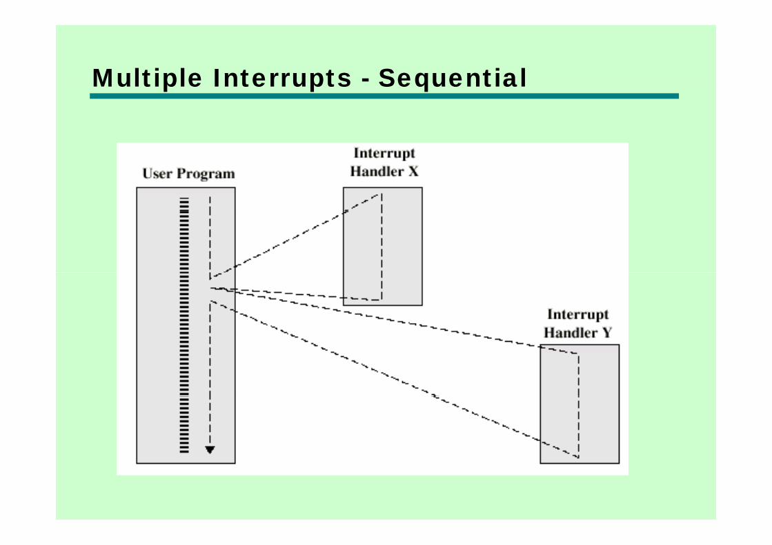
Multiple Interrupts - Sequentialp p q

Multiple Interrupts – Nestedp p
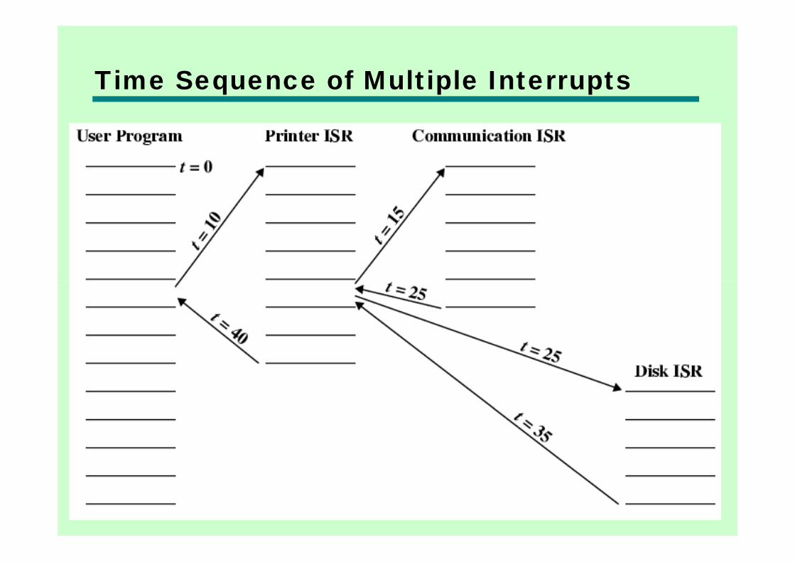
Time Sequence of Multiple Interruptsq p p

Connectingg• All the units must be connected
ff f f d ff• Different type of connection for different type of unit—Memory—Input/Output—CPU
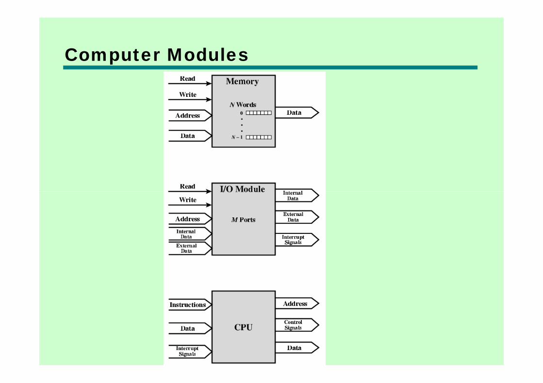
Computer Modulesp

Memory Connectiony• Receives and sends data
dd ( f l )• Receives addresses (of locations)• Receives control signals
—Read—Write—Timing

Input/Output Connection(1)p p ( )• Similar to memory from computer’s
viewpointviewpoint• Output
—Receive data from computer—Send data to peripheral
• Input—Receive data from peripheralp p—Send data to computer
Input/Output Connection(2)p p ( )• Receive control signals from computer
S d l l h l• Send control signals to peripherals—e.g. spin disk
• Receive addresses from computer—e.g. port number to identify peripheralg p y p p
• Send interrupt signals (control)

CPU Connection• Reads instruction and data
d ( f )• Writes out data (after processing)• Sends control signals to other units• Receives (& acts on) interrupts

Buses• There are a number of possible
interconnection systemsinterconnection systems• Single and multiple BUS structures are
most common• e.g. Control/Address/Data bus (PC)• e.g. Unibus (DEC-PDP)
What is a Bus?• A communication pathway connecting two
or more devicesor more devices• Usually broadcast • Often grouped
—A number of channels in one bus—e.g. 32 bit data bus is 32 separate single bit
channels• Power lines may not be shown
Data Bus• Carries data
R b th t th i diff b t —Remember that there is no difference between “data” and “instruction” at this level
Width i k d t i t f • Width is a key determinant of performance
b—8, 16, 32, 64 bit
Address bus• Identify the source or destination of data
C d d• e.g. CPU needs to read an instruction (data) from a given location in memory
• Bus width determines maximum memory capacity of system—e.g. 8080 has 16 bit address bus giving 64k
address space
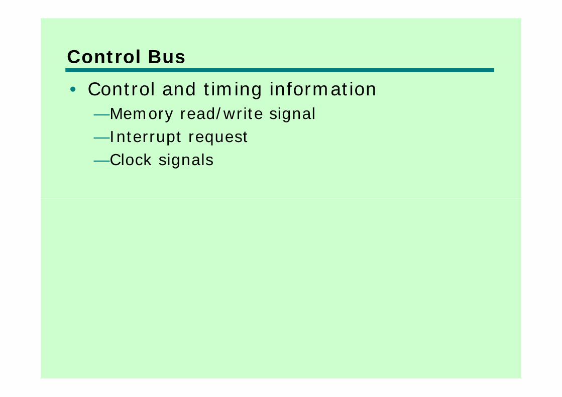
Control Bus• Control and timing information
M d/ it i l—Memory read/write signal—Interrupt request
Cl k i l—Clock signals

Bus Interconnection Scheme
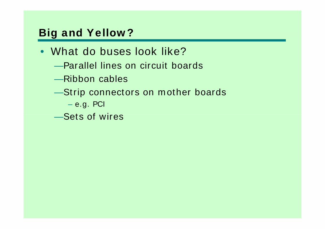
Big and Yellow?g• What do buses look like?
P ll l li i it b d—Parallel lines on circuit boards—Ribbon cables
S i h b d—Strip connectors on mother boards– e.g. PCI
Sets of i es—Sets of wires
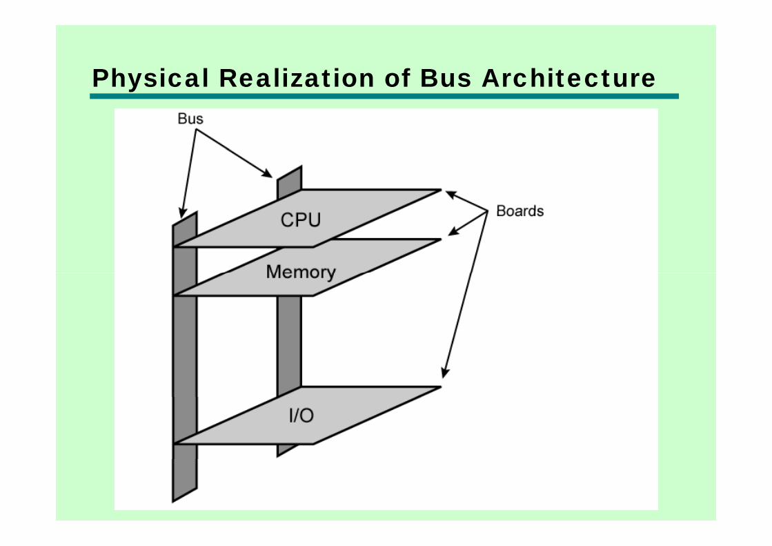
Physical Realization of Bus Architecturey

Single Bus Problemsg• Lots of devices on one bus leads to:
P ti d l—Propagation delays– Long data paths mean that co-ordination of bus use
can adversely affect performancecan adversely affect performance– If aggregate data transfer approaches bus capacity
• Most systems use multiple buses to Most systems use multiple buses to overcome these problems
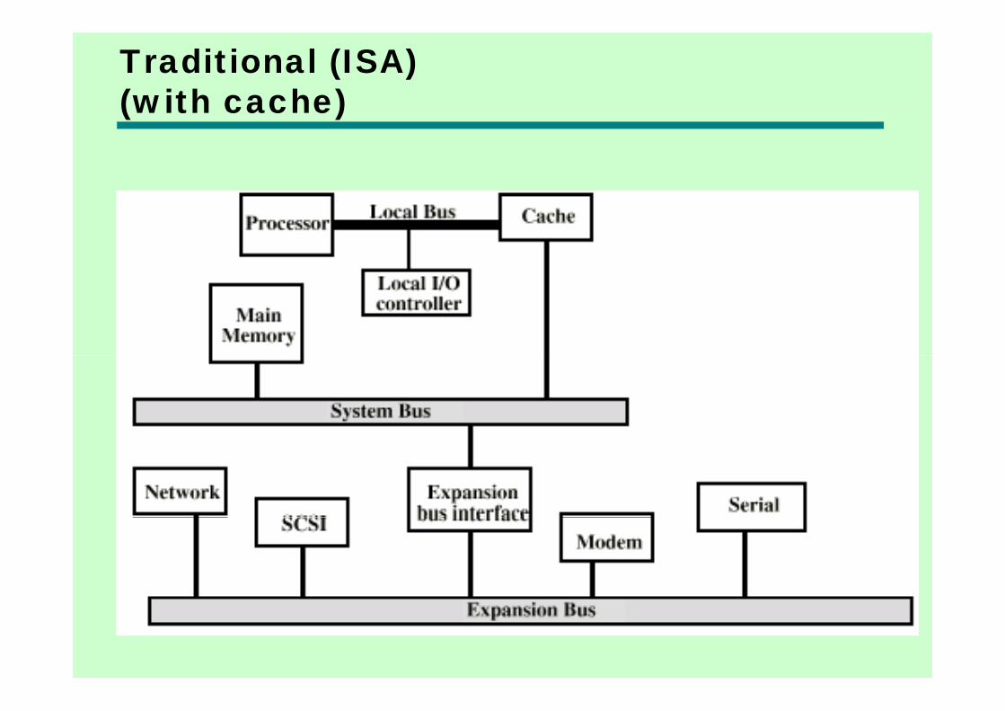
Traditional (ISA)(with cache)( )

High Performance Busg

Bus Typesyp• Dedicated
S t d t & dd li—Separate data & address lines• Multiplexed
—Shared lines—Address valid or data valid control line—Advantage - fewer lines—Disadvantages
– More complex control– Ultimate performance
Bus Arbitration• More than one module controlling the bus
C d ll• e.g. CPU and DMA controller• Only one module may control bus at one
time• Arbitration may be centralised or b t at o ay be ce t a sed o
distributed

Centralised or Distributed Arbitration• Centralised
Si l h d d i t lli b —Single hardware device controlling bus access– Bus Controller– Arbiter– Arbiter
—May be part of CPU or separate• Distributed• Distributed
—Each module may claim the busC t l l i ll d l—Control logic on all modules
Timingg• Co-ordination of events on bus
S h• Synchronous—Events determined by clock signals—Control Bus includes clock line—A single 1-0 is a bus cycle—All devices can read clock line—Usually sync on leading edge—Usually a single cycle for an event
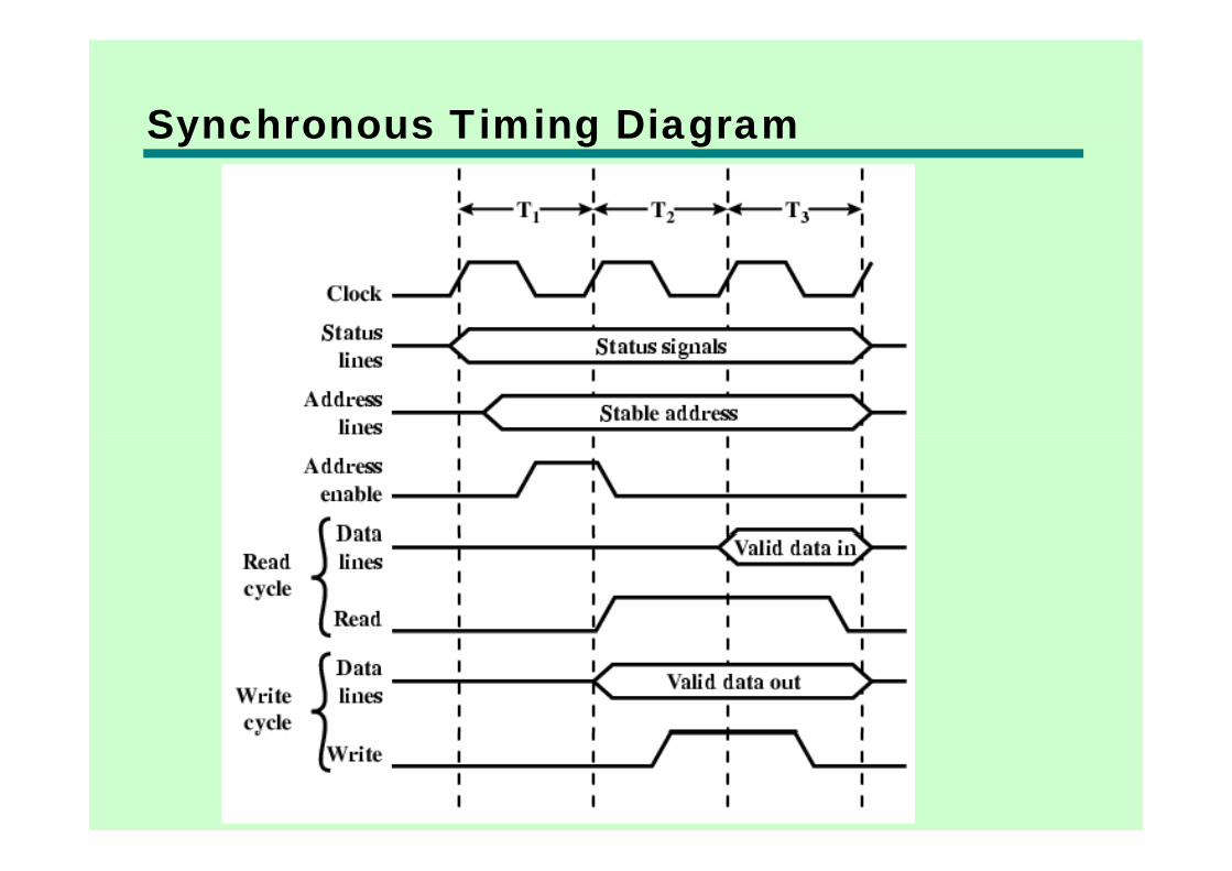
Synchronous Timing Diagramy g g

Asynchronous Timing – Read Diagramy g g
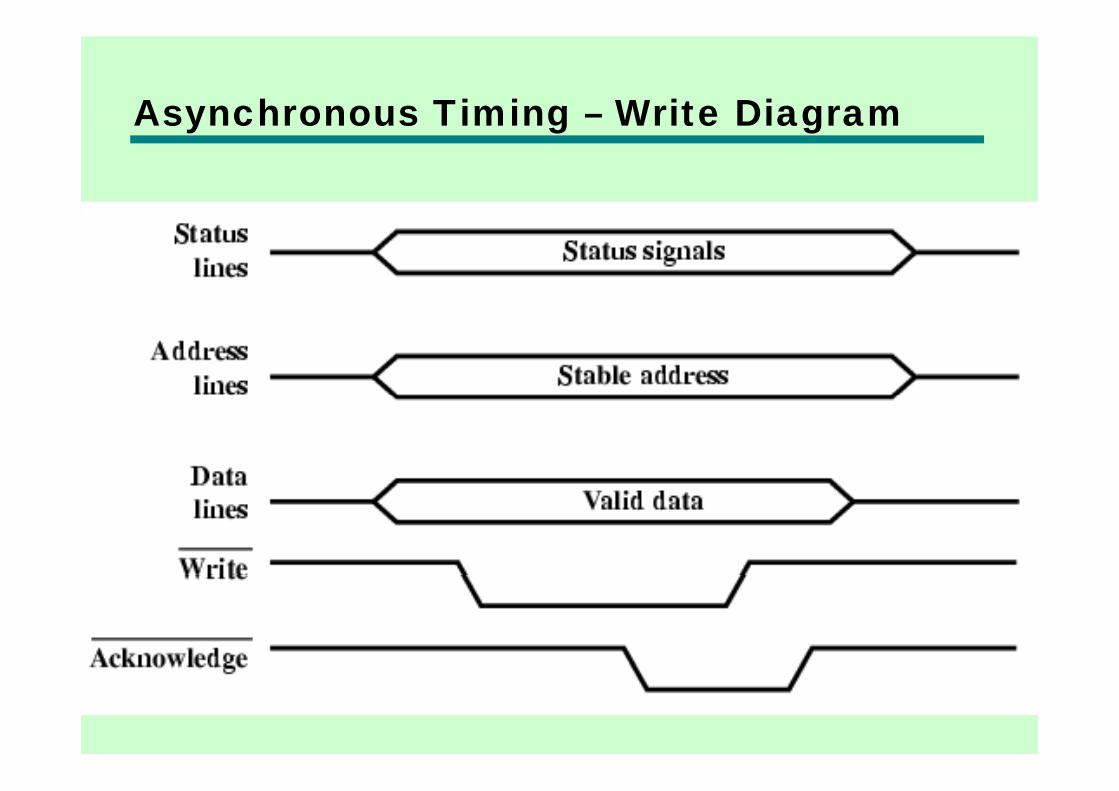
Asynchronous Timing – Write Diagramy g g

PCI Bus• Peripheral Component Interconnection
l l d bl d• Intel released to public domain• 32 or 64 bit• 50 lines
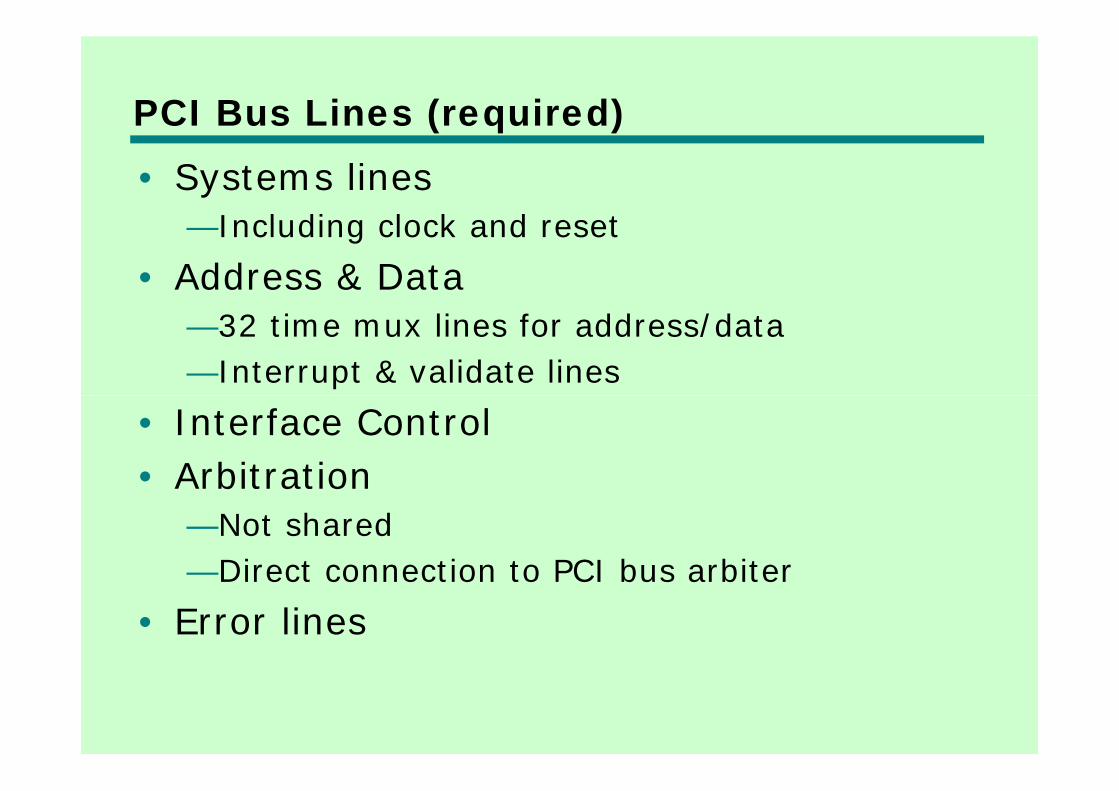
PCI Bus Lines (required)( q )• Systems lines
I l di l k d t—Including clock and reset• Address & Data
—32 time mux lines for address/data—Interrupt & validate lines
• Interface Control• ArbitrationArbitration
—Not shared—Direct connection to PCI bus arbiterDirect connection to PCI bus arbiter
• Error lines
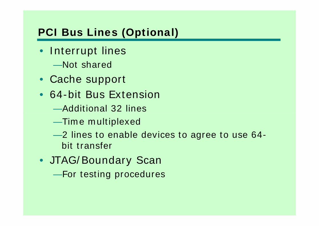
PCI Bus Lines (Optional)( p )• Interrupt lines
N t h d—Not shared• Cache support• 64-bit Bus Extension
—Additional 32 lines—Time multiplexed—2 lines to enable devices to agree to use 64-g
bit transfer• JTAG/Boundary Scan/ y
—For testing procedures
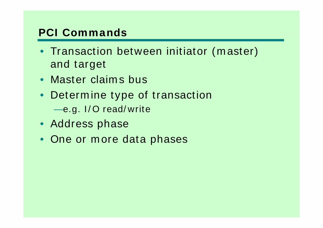
PCI Commands• Transaction between initiator (master)
and targetand target• Master claims bus• Determine type of transaction
—e.g. I/O read/write• Address phase• One or more data phases• One or more data phases

PCI Read Timing Diagramg g

PCI Bus Arbiter

PCI Bus Arbitration

Foreground Readingg g• Stallings, chapter 3 (all of it)
d / f/ b /b /• www.pcguide.com/ref/mbsys/buses/
• In fact, read the whole site!• www pcguide com/• www.pcguide.com/


![Sistemi Operativi [William Stallings]](https://img.dokumen.tips/doc/110x75/543cd117b1af9fc42e8b4811/sistemi-operativi-william-stallings.jpg)


