Embed Size (px)
Citation preview
International:
Connect One Ltd. 20 Atir Yeda Street Kfar Saba 44643, Israel Phone: +972-9-766-0456 Fax: +972-9-766-0461 Email: [email protected] http://www.connectone.com
USA: Connect One Semiconductors, Inc. 560 S. Winchester Blvd. Suite 500 San Jose, CA 95128 Tel: (408) 572-5675 Fax: (408) 572-5601
Pub. No. 20-1000-07, May 2011
iChip WiFi Configuration
June 2011
Ver. 2.00
Copyright © Connect One Ltd., 2008-2011
Connect One
Configuring WiFi on iChip CO2128/CO2144 2
The information in this document is subject to change without notice and shall not be
construed as a commitment on the part of Connect One.
Connect One assumes no liability for any errors that may appear in this document.
The software described in this document is furnished under a license agreement and may
be used or copied only in accordance with the terms of such a license agreement. It is
forbidden by law to copy the software on any medium except as specifically allowed in
the license agreement. No part of this document may be reproduced or transmitted in any
form or by any means, electronic or mechanical, including but not limited to
photocopying, recording, transmitting via fax and/or modem devices, scanning, and/or
information storage and retrieval systems for any purpose without the express written
consent of Connect One.
iChip, AT+i, Secure Socket iWiFi, miniSocket iWiFi, Nano WiReach and Connect One
are trademarks of Connect One Ltd.
Copyright 2000-20011 Connect One Ltd. All rights reserved.
Connect One
Configuring WiFi on iChip CO2128/CO2144 3
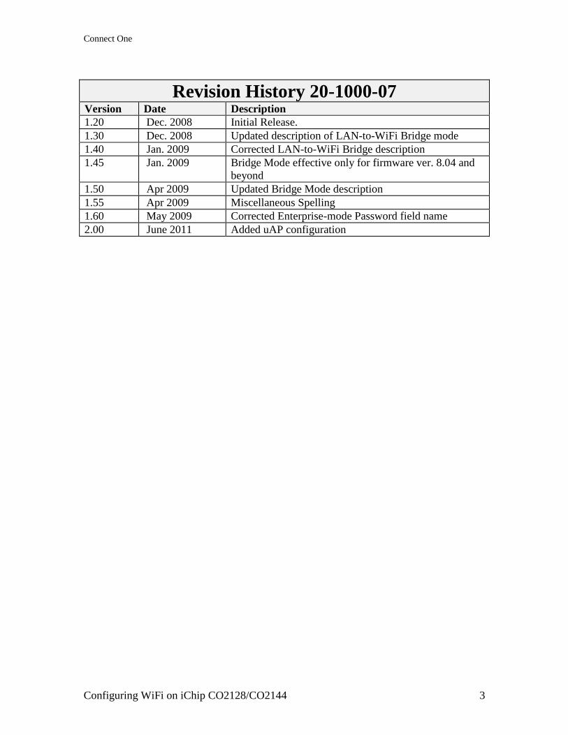
Revision History 20-1000-07 Version Date Description
1.20 Dec. 2008 Initial Release.
1.30 Dec. 2008 Updated description of LAN-to-WiFi Bridge mode
1.40 Jan. 2009 Corrected LAN-to-WiFi Bridge description
1.45 Jan. 2009 Bridge Mode effective only for firmware ver. 8.04 and
beyond
1.50 Apr 2009 Updated Bridge Mode description
1.55 Apr 2009 Miscellaneous Spelling
1.60 May 2009 Corrected Enterprise-mode Password field name
2.00 June 2011 Added uAP configuration
Connect One
Configuring WiFi on iChip CO2128/CO2144 4
Table of Contents
Introduction ......................................................................................................................... 5
Initial Connection................................................................................................................ 5
WiFi Related Reports .......................................................................................................... 5
RP11 ................................................................................................................................ 5
!RP11 .............................................................................................................................. 6
RP10 ................................................................................................................................ 6
!RP10 .............................................................................................................................. 6
RP20 ................................................................................................................................ 6
Connecting to a Specific Access Point ............................................................................... 7
Multiple Access Points ....................................................................................................... 7
WiFi Security Configuration............................................................................................... 8
Wired Equivalent Privacy (WEP) Security..................................................................... 8
Wireless Protected Access (WPA/WPA2) Pre-Shared key (PSK) Security ................... 9
Enterprise Mode Security ............................................................................................. 10
AD-HOC Mode ................................................................................................................. 12
Security in AD-HOC mode ........................................................................................... 12
IP Address Assignment in AD-HOC mode .................................................................. 12
Ad-Hoc mode Behavior in a MultiSSID environment ................................................. 13
iChip Behavior in the Event of a Lost Link ...................................................................... 13
WiFi related Power Management .................................................................................... 13
Introduction ................................................................................................................... 13
Roaming with Wireless-LAN ........................................................................................... 15
Introduction ................................................................................................................... 15
iChip Behavior when AP Signal Becomes Weak ......................................................... 16
Roaming Parameters Description ..................................................................................... 17
+iWROM — Enable Roaming in WiFi ........................................................................ 17
+iWPSI — Periodic WiFi Scan Interval ....................................................................... 17
+iWSRL — SNR Low Threshold ................................................................................. 17
+iWSRH — SNR High Threshold ................................................................................ 17
Monitoring WiFi Performance in iChip‘s Configuration Web Site.................................. 18
Configuring LAN-to-WiFi Bridge Mode.......................................................................... 19
Introduction and Scope ................................................................................................. 19
General Description ...................................................................................................... 19
New AT+I Commands to support LAN-to-WiFi Mode ............................................... 22
AT+iBRM – Bridge Mode ........................................................................................ 22
AT+iMACF – MAC Forward ................................................................................... 22
Micro Access-Point (uAP) Mode...................................................................................... 23
Supported AP functionality........................................................................................... 23
Non-Configurable AP Parameter Settings .................................................................... 23
Configurable iChip Parameters used in AP mode ........................................................ 24
iChip AT+i Commands used in relation to uAP mode ................................................. 24

Connect One
Configuring WiFi on iChip CO2128/CO2144 5
Introduction
iChip CO2128, iChip CO2144, Secure Socket iWiFi, miniSocket iWiFi and Nano
WiReach support 802.11b/g WiFi connectivity using the Marvel 8686 WiFi chipset.
The iChip firmware contains built-in drivers that support the WiFi chipset as well as a
WPA/WPA2 supplicant allowing for a choice of WEP or WPA/WPA2 PSK or Enterprise
mode security over the wireless connection.
iChip contains a variety of parameters associated with WiFi connectivity, which permit
configuring the connection profile and its characteristics. iChip may be configured for a
WiFi connection in infrastructure mode via an Access Point (AP) or as part of a local
WiFi cluster using Ad-Hoc mode.
iChip also supports a Roaming mode, allowing it to seamlessly transfer between Access
Points, in support of mobile devices that need to be on the move across geographical
distances larger than the AP‘s supported range.
Several reports are made available to monitor the WiFi environment and quality of
connection.
This document details the commands and parameters that are used to configure, control
and monitor a WiFi connection when using an iChip based product.
Initial Connection
Assuming all WiFi related parameters are cleared to their default value, as is the case
after a Factory-Defaults setting (AT+iFD), iChip will attempt to associate and connect to
the closest available Access Point (AP) that does not have any security configured. When
iChip senses several AP‘s in its vicinity, it determines the closest AP according to the
strongest received signal.
If no secure-less AP is detected, iChip will endlessly continue trying to locate one.
WiFi Related Reports
Several iChip reports are related to information regarding the WiFi environment.
RP11
The AT+iRP11 report instructs iChip to scan the environment and report all Access
Points (AP‘s) in its vicinity.
For example,
AT+iRP11
Jetta,WPA2,1
GANG_TEST,NONE,1
Bora,NONE,1
Levanto,WEP,1
Sirocco,WPA,1
Blue-I The Lab,WEP,1
Mistral,WEP,1
3Com,NONE,1
I/OK
Each response line contains one AP details including its SSID, Security setting and signal
strength (0-low; 1-good; 2-excellant).
Connect One
Configuring WiFi on iChip CO2128/CO2144 6
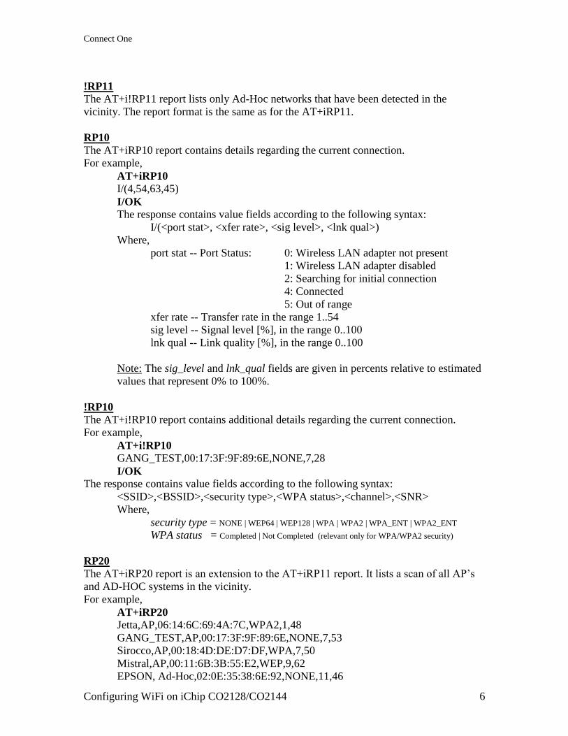
!RP11
The AT+i!RP11 report lists only Ad-Hoc networks that have been detected in the
vicinity. The report format is the same as for the AT+iRP11.
RP10
The AT+iRP10 report contains details regarding the current connection.
For example,
AT+iRP10
I/(4,54,63,45)
I/OK
The response contains value fields according to the following syntax:
I/(<port stat>, <xfer rate>, <sig level>, <lnk qual>)
Where,
port stat -- Port Status: 0: Wireless LAN adapter not present
1: Wireless LAN adapter disabled
2: Searching for initial connection
4: Connected
5: Out of range
xfer rate -- Transfer rate in the range 1..54
sig level -- Signal level [%], in the range 0..100
lnk qual -- Link quality [%], in the range 0..100
Note: The sig_level and lnk_qual fields are given in percents relative to estimated
values that represent 0% to 100%.
!RP10
The AT+i!RP10 report contains additional details regarding the current connection.
For example,
AT+i!RP10
GANG_TEST,00:17:3F:9F:89:6E,NONE,7,28
I/OK
The response contains value fields according to the following syntax:
<SSID>,<BSSID>,<security type>,<WPA status>,<channel>,<SNR>
Where,
security type = NONE | WEP64 | WEP128 | WPA | WPA2 | WPA_ENT | WPA2_ENT
WPA status = Completed | Not Completed (relevant only for WPA/WPA2 security)
RP20
The AT+iRP20 report is an extension to the AT+iRP11 report. It lists a scan of all AP‘s
and AD-HOC systems in the vicinity.
For example,
AT+iRP20
Jetta,AP,06:14:6C:69:4A:7C,WPA2,1,48
GANG_TEST,AP,00:17:3F:9F:89:6E,NONE,7,53
Sirocco,AP,00:18:4D:DE:D7:DF,WPA,7,50
Mistral,AP,00:11:6B:3B:55:E2,WEP,9,62
EPSON, Ad-Hoc,02:0E:35:38:6E:92,NONE,11,46
Connect One
Configuring WiFi on iChip CO2128/CO2144 7
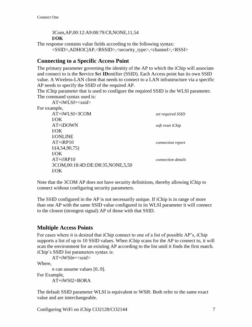
3Com,AP,00:12:A9:08:79:C8,NONE,11,54
I/OK
The response contains value fields according to the following syntax:
<SSID>,ADHOC|AP,<BSSID>,<security_type>,<channel>,<RSSI>
Connecting to a Specific Access Point
The primary parameter governing the identity of the AP to which the iChip will associate
and connect to is the Service Set IDentifier (SSID). Each Access point has its own SSID
value. A Wireless-LAN client that needs to connect to a LAN infrastructure via a specific
AP needs to specify the SSID of the required AP.
The iChip parameter that is used to configure the required SSID is the WLSI parameter.
The command syntax used is:
AT+iWLSI=<ssid>
For example,
AT+iWLSI=3COM set required SSID
I/OK
AT+iDOWN soft reset iChip
I/OK
I/ONLINE
AT+iRP10 connection report
I/(4,54,90,75)
I/OK
AT+i!RP10 connection details
3COM,00:18:4D:DE:D8:35,NONE,5,50
I/OK
Note that the 3COM AP does not have security definitions, thereby allowing iChip to
connect without configuring security parameters.
The SSID configured in the AP is not necessarily unique. If iChip is in range of more
than one AP with the same SSID value configured in its WLSI parameter it will connect
to the closest (strongest signal) AP of those with that SSID.
Multiple Access Points
For cases where it is desired that iChip connect to one of a list of possible AP‘s, iChip
supports a list of up to 10 SSID values. When iChip scans for the AP to connect to, it will
scan the environment for an existing AP according to the list until it finds the first match.
iChip‘s SSID list parameters syntax is:
AT+iWSIn=<ssid>
Where,
n can assume values [0..9].
For Example,
AT+iWSI2=BORA
The default SSID parameter WLSI is equivalent to WSI0. Both refer to the same exact
value and are interchangeable.
Connect One
Configuring WiFi on iChip CO2128/CO2144 8
AP scanning always begins with WLSI (or WST0) and commences to WSI1 only if no
AP with WLSI is found. Scanning continues with the next WSIn until a matching AP is
found, a WSIn parameter is empty or all 10 SSID‘s have been scanned.
If a matching AP is found, iChip will attempt to associate and connect to it. Otherwise, it
will reiterate scanning the entire list again.
Note that the order of the SSID values in the list defines the connection priority.
Furthermore, note that if a WSIn value is cleared, iChip will not scan past that element
even if additional values exist further down the list.
WiFi Security Configuration
iChip supports several WiFi security standards when connecting to an AP in
infrastructure mode. iChip parameters are used to configure the security setting that is to
be used for each AP to which iChip will connect. The security standards supported are:
WEP with 64 bit keys
WEP with 128 bit keys
WPA with TKIP encryption in PSK mode
WPA2 with AES encryption in PSK mode
WPA-TKIP Enterprise PEAP-MSCHAPv2 with RADIUS server
WPA2-AES Enterprise PEAP-MSCHAPv2 with RADIUS server
The iChip parameter WSTn defines the security method used by the AP. n is determined
according to the matching SSID with which iChip connected to the AP.
The possible values for WSTn are:
0 = No Security
1 = WEP64
2 = WEP128
3 = WPA PSK
4 = WPA2 PSK
5 = WPA Enterprise
6 = WPA2 Enterprise
Wired Equivalent Privacy (WEP) Security
When using WEP security the AP and client need to agree on an encryption/decryption
key that is either 5 bytes for WEP64 or 13 bytes for WEP128. iChip contains a 4-key
repository for WEP keys, However, only one of those keys is active at a time. A fifth
parameter contains the index of the WEP key to use. The idea behind this scheme is the
ability to change the use of a key with a simple change of index value and without
erasing the actual key value, so it is ready for reuse at a later time. This scheme applies
only to the default SSID stored in WST0 (also called WLSI). WEP keys for additional
AP‘s who‘s SSID is defined in WST1 to WST9 are single keys stored for each SSID.
The 4-key repository used with WSI0 is stored in the WLKn iChip parameters, where n is
in the range [1..4]. the index of the active key to be used is stored in WLKI.
For example,
AT+iWLK1=12AA4F5C32
AT+iWLK2=A4FF232218
… etc.
AT+iWLKI=2 defines use of the WEP key stored in WLK2 (A4FF232218).
Connect One
Configuring WiFi on iChip CO2128/CO2144 9
It is not necessary to configure all 4 WEP keys. Setting a value to one key would be
enough, provided that the WLKI parameter contains the index to the configured WLKn
parameter.
Single WEP keys may also be defined for multi-SSID environments. The iChip
parameter list used is WKYn, with n in the range [1..9] and corresponding to the AP with
SSID stored in WSIn.
For example,
AT+iWKY1=34FB1C2356
AT+iWKY2=AF4D66EF10
etc.
A checklist setting for a WEP environment will entail configuring the following
parameters:
1. AT+iWLSI=<ssid> SSID of required AP.
2. AT+iWST0=<1 or 2> Define WEP64 or WEP128 security.
3. AT+iWLK1=<WEP key> Define a WEP key using Hex digits.
4. AT+iWLKi=<WEP key> With WLSI (WSI0) you may define additional WEP keys. 1=2..4
5. AT+iWLKI=1 Define which WEP key to use. Relevant only to WLSI (WSI0).
6. AT+iWSIi=<ssid> Define additional AP’s for a multi-SSID environment. i=1..9.
7. AT+iWKYi=<WEP key> Define single WEP keys for use in a multi-SSID environment. i=1..9
8. AT+iWSTi=<1 or 2> Define WEP64 or WEP128 security. i=1..9
WEP security has several vulnerabilities and can be rather easily cracked. It is advised
not to use WEP security in security sensitive networks.
Wireless Protected Access (WPA/WPA2) Pre-Shared key (PSK) Security
WPA/WPA2 PSK mode is based on a shared key encryption/decryption scheme using
encryption methods that are significantly stronger than those used for WEP. An agreed
upon Pass-phrase is configured in both the AP and the client and used together with the
SSID to create a symmetric encryption/decryption key, which in turn is used with TKIP
(WPA) or AES (WPA2) cipher engines.
When configuring iChip for WPA/WPA2 PSK mode security, the Pass Phrase needs to
be configured in the WLPP parameter.
For example,
AT+iWLPP=<passphrase>
The passphrase used is an ASCII string consisting of 8-83 characters.
In multi-SSID environments each SSID setting can have a separate associated passphrase
configured in the iChip parameter list WPPn. n corresponds to the SSID stored in WSIn.
WLPP and WPP0 are equivalent and refer to the same exact value.
When setting or updating a passphrase, iChip requires about 20 seconds before returning
the I/OK, since it needs to calculate a convolution between the passphrase and the SSID.
Similarly, when a passpharse exists, updating the corresponding SSID will acquire the
same delay.
Connect One
Configuring WiFi on iChip CO2128/CO2144 10
A checklist setting for a WPA/WPA2 environment will entail configuring the following
parameters:
1. AT+iWLSI=<ssid> SSID of required AP.
2. AT+iWST0=<3 or 4> Define WPA or WPA2 PSK security.
3. AT+iWLPP=<passphrase> Define the passphrase.
4. AT+iWSIi=<ssid> Define additional AP’s for a multi-SSID environment. i=1..9.
5. AT+iWPPi=<passphrase > Define passphrases for a multi-SSID environment. i=1..9
6. AT+iWSTi=<3 or 4> Define WPA or WPA2 PSK security. i=1..9
Enterprise Mode Security
The Enterprise Mode WiFi security approach focuses on a framework for providing
centralized authentication and dynamic key distribution for encryption.
Central to this proposal are two main elements:
• IEEE 802.1x: a standard for port-based network access control.
• EAP: Extensible Authentication Protocol that allows wireless client adapters
to communicate with different back-end servers such as a Remote Access
Dial-In User Service (RADIUS server).
iChip supports Enterprise Mode WiFi security from firmware version 8.01 and
above.
Two related parameters have been added in order to support configuration of Enterprise
Mode:
+iEUSN – Enterprise User-Name: which contains the Radius Domain and
specific client‘s User-Name.
+iEPSW – Enterprise Password: which contains the Password associated with the
User-Name in EUSN.
The EUSN parameter syntax is:
AT+iEUSN=<Domain>\<user-name>
Where,
Domain is the RADIUS server domain name
user-name is a User-Name defined in the RADIUS server with remote
login rights.
For example,
AT+iEUSN=RADIUS\userA
The EPSW parameter syntax is:
AT+iEPSW=<password>
password must be the correct password defined in the RADIUS server for the User
configured in EUSN.
In addition, the RADIUS server‘s certificate must be authenticated by iChip as part of the
Enterprise Mode negotiation. Therefore, the RADIUS server‘s CA (Certificate Authority)
Connect One
Configuring WiFi on iChip CO2128/CO2144 11
must be stored in iChip‘s CA parameter. The CA parameter accepts a standard PEM
coded certificate.
For example,
AT+iCA= ----BEGIN CERTIFICATE-----
MIIEizCCA3OgAwIBAgIQPcRpW5Ybo6FKV8k5zcDBDTANBgkqhkiG9w0BAQUFADBE
MRUwEwYKCZImiZPyLGQBGRYFbG9jYWwxFjAUBgoJkiaJk/IsZAEZFgZyYWRpdXMx
EzARBgNVBAMTCkV4YW1wbGUgQ0EwHhcNMDgwNzIxMDYwMDU2WhcNMTMwNzIxMDYx
MDE2WjBEMRUwEwYKCZImiZPyLGQBGRYFbG9jYWwxFjAUBgoJkiaJk/IsZAEZFgZy
YWRpdXMxEzARBgNVBAMTCkV4YW1wbGUgQ0EwggEiMA0GCSqGSIb3DQEBAQUAA4IB
DwAwggEKAoIBAQCXvtkwCDXMCRXBLRsSi7zFbAmJyyowyp+l6GLJTkGEB6jmmus1
dCeKxi55skw5M+MeIy2TgUzf2iV0a4kSgHUaGuiGqia8kcE3yGQa4kq241JOCb/w
m6bx9p0xVFdCyXSBqTFTRTUFkpq074QDnwLbhGmuhBnt22p3xs3LKI+y3lp3v1Gf
z0EJ2yRX1ye/J+skUIZvaFPhrw+85CfPcMLcPvfQ+2t3VJs89NBuak8WZJOn7sMl
zNSmbwA1wIrLt4kkqk6pOKAJ0un9izosWUaP0/qjhG7P2ccVkYAcWWq1ocgIMnZU
AAVSfPM2KUiRQGNm+rDJYF0Yrdw2BrdTLlDnAgMBAAGjggF3MIIBczATBgkrBgEE
AYI3FAIEBh4EAEMAQTALBgNVHQ8EBAMCAYYwDwYDVR0TAQH/BAUwAwEB/zAdBgNV
HQ4EFgQUPBNIhTMs/pnCcqlJTEv4hpAqaL0wggELBgNVHR8EggECMIH/MIH8oIH5
oIH2hoG3bGRhcDovLy9DTj1FeGFtcGxlJTIwQ0EsQ049cmFkaXVzLXRzdCxDTj1D
RFAsQ049UHVibGljJTIwS2V5JTIwU2VydmljZXMsQ049U2VydmljZXMsQ049Q29u
ZmlndXJhdGlvbixEQz1yYWRpdXMsREM9bG9jYWw/Y2VydGlmaWNhdGVSZXZvY2F0
aW9uTGlzdD9iYXNlP29iamVjdENsYXNzPWNSTERpc3RyaWJ1dGlvblBvaW50hjpo
dHRwOi8vcmFkaXVzLXRzdC5yYWRpdXMubG9jYWwvQ2VydEVucm9sbC9FeGFtcGxl
JTIwQ0EuY3JsMBAGCSsGAQQBgjcVAQQDAgEAMA0GCSqGSIb3DQEBBQUAA4IBAQCK
3GxozfOp6IiSRHNx08zfKXPXyDZrfItsy6FYSk/aLNAUW6y6BdwyCIDSLSDCGawD
ToPiA3reu0rRStrEUWq3D9JnzDoOL3h4MzGL6ddzN6SVigKOCvDxX31bZiq+h73i
8XbfgpSNdKpu96itfRlDdBa9mFegfyTIBI5Z472iFKIHoSKfdTjfCh6Mf5+SGSdF
9GlcRPPTQOrxe7FKzdW+4lShWBanxOOSW3a5q7SbIc4a1dP1xOmzRauwIjkSW00J
pUaHscjALqJlsKqkSwrUNFlWxxvzVsMEfyJE/fEr87XhjeeKrPXV2ex44bvyaJBt
LEk8tY2O5JcAPTIKrMBO
-----END CERTIFICATE--------
I/OK
The WSTn parameter receives values 5 or 6 to define Enterprise Mode security:
If WSTn=5, iChip shall try to associate only to AP‘s that publish WPA-IE-
802.1x (and not PSK) in their beacon.
If WSTn=6, iChip shall try to associate only to AP‘s that publish RSN-IE-802.1x
(and not PSK) in their beacon.
A checklist setting for Enterprise security environment will entail configuring the
following parameters:
1. AT+iCA=<ca> Certificate Authority that signed the RADIUS server’s
certificate. 2. AT+iWLSI=<ssid> SSID of required AP.
3. AT+iWST0=<5 or 6> Define WPA or WPA2 Enterprise security
4. AT+iEUSN=<dom>\<usr> Define RADIUS Domain & User-Name
5. AT+iEPSW=<pass> Define User’s Password
6. AT+iWSIi=<ssid> Define additional AP’s for a multi-SSID environment. i=1..9.
7. AT+iWSTi=<5 or 6> Define WPA or WPA2 Enterprise security. i=1..9
Configuring a RADIUS Server
The following link may be consulted in order to configure a RADIUS server on a
Windows Server machine:
http://support.mof.go.th/radius_windows.html
Connect One
Configuring WiFi on iChip CO2128/CO2144 12
AD-HOC Mode
On wireless computer networks, AD-HOC mode is a method for wireless devices to
directly communicate with each other. Operating in AD-HOC mode allows all wireless
devices within range of each other to discover and communicate in peer-to-peer fashion
without involving central Access Points. To set up an AD-HOC wireless network, each
wireless adapter must be configured for AD-HOC mode as opposed to the alternative
infrastructure mode. In addition, all wireless adapters on an AD-HOC network must use
the same SSID and the same channel number.
The first system configured for AD-HOC mode is called the Creator. It knows that is
first, since it tries to sense if there are other systems in its vicinity in AD-HOC mode
(using the same SSID and communicating on the same channel) – and cannot discover
any. Additional systems are called Joiners, since they sense that other AD-HOC systems
with the specified SSID exist on the specified channel and they join in.
The AD-HOC network is self-maintained and will continue to exist even if the Creator
goes offline. Note that in an AD-HOC network, all members of the network must:
1. Have the same SSID
2. Use the same channel
3. Be in range of all other systems
iChip supports AD-HOC mode configuration by setting the WiFi channel and setting an
SSID value that is preceded by the ‗!‘ character. The ‗!‘ is not part of the SSID. For
example, to setup an AD-HOC SSID of ―MYNET‖ specify in iChip ―!MYNET‖.
A checklist setting for AD-HOC will entail configuring the following parameters:
1. AT+iWLCH=<channel> Channel number in the range 1 to 11. 12 or 13 may be used in
some countries as well. 2. AT+iWLSI=!<ssid> SSID of required AD-HOC Network.
Security in AD-HOC mode
Only WEP64 or WEP128 security may be implemented when in AD-HOC mode. See
WEP security above for configuration details.
IP Address Assignment in AD-HOC mode
AD-HOC mode only provides for connectivity at the WiFi level. If an AD-HOC
connection needs to support TCP/IP communications each participant system must
somehow get an IP address. Furthermore, all IP addresses need to be on the same subnet.
As in other situations, IP addresses can either be pre-assigned in a fixed manner or one of
the systems needs to act as a DHCP server. Note however, that when basing a solution on
a DHCP server, the DHCP server must be part of the AD-HOC network before the other
participants can get IP addresses and start communications.
An iChip can act as a DHCP server, if needed, by setting the DIP and DPSZ parameters.
More information on this can be sought in the AT+i Programmers Manual.

Connect One
Configuring WiFi on iChip CO2128/CO2144 13
Ad-Hoc mode Behavior in a MultiSSID environment
After power-up or hardware or software reset, iChip starts scanning for APs or Ad-
Hoc networks in its vicinity, at intervals set by the WPSI parameter. iChip first
refers to the value in the WLSI parameter. If WLSI refers to anAd-Hoc network,
iChip scans for all Ad-Hoc networks in its vicinity. It attempts to join the first Ad-
Hoc network whose SSID is listed in the WSIn parameter. If, however, after three
consecutive scans, no such network is found – iChip creates its own network
according to the WLSI (WSI0) SSID and stops scanning.
If WLSI is set to (!), iChip scans only for any available Ad-Hoc network (regardless
its SSID) and tries to connect to the network with the best signal. (correlates to
WLSI="").
If WLSI is set to (*), iChip will not scan and remain disconnected.
iChip Behavior in the Event of a Lost Link
If the WiFi connection is lost while no active connection is underway, iChip starts
periodic scanning for APs and attempts to connect to the AP having the highest priority.
After associating with an AP, iChip starts its DHCP client and monitors the SNR level of
the AP it is associated with.
If the WiFi connection is lost during active operation, iChip waits for an IP activity
command from the host. When such a command is sent, iChip performs a software reset
and starts scanning for APs. iChip responds to the host with ERROR(074) to indicate
that the current connection has been lost.
WiFi related Power Management
Introduction
The Power Management mechanism in iChip controls both the CO2128/CO2144 power
modes as well as the Marvell 8686 power modes.
iChip‘s power management is enabled by setting the PSE (Power Save Enable) parameter
to a value between 1 and 255 (the default value is 0 and means that the power saving
mechanism is disabled). The PSE value is given in seconds and defines the number of
idle seconds that will cause iChip to go into power save mode.
The Marvell‘s 8686 power management is enabled by setting the WLPS (Wireless Power
Save) parameter to a value between 1 and 5 (the default value is 0 and means that the
Wireless power saving mechanism is disabled). The WLPS value is given in number of
beacons periods, where the beacon period is determined by the AP.
In Ad-Hoc networks, the value of the ATIM window controls whether the power save
operation is permitted in the network or not. If the value of the ATIM window is 0, than
the participating stations are not permitted to enter power save mode. The value of the
ATIM window is chosen by the Ad-Hoc creator and then the same value is adopted by all
the joiners.
When iChip is the creator it sets the ATIM window to a non zero value if WLPS is non
zero. With a non-zero ATIM window value, every station participating in the Ad-Hoc
network needs to be awake during the ATIM window, which follows a receipt of the
Connect One
Configuring WiFi on iChip CO2128/CO2144 14
beacon. During this window any participating node may notify a peer that it has
information to send. If the peer acknowledges, the sending and receiving node stay awake
for the duration of the beacon period and exchange information. Other systems are
allowed to doze (enter Sleep mode) for the duration of the Beacon period after the ATIM
window is done. The ATIM window value is in units of TU (=1.024mSec).
iChip Power Modes :
The iChip frimware has 3 power modes:
Normal mode – in this mode, the firmware checks if it needs to enter sleep mode
every 40 ms.
Several conditions must be fulfilled before entering sleep mode:
o The PSE parameter value is non-zero (i.e. between 1 and 255 seconds).
o The number of seconds that have elapsed without any activity on the Host
serial port is more than the value of the PSE parameter.
o The number of seconds that have elapsed without incoming data from the
WiFi (network) is more than the value of the PSE parameter.
o There is no ongoing DHCP process (i.e. iChip has a valid IP address).
o There is no data waiting to be transmitted on one or more of the active
sockets.
o In case of Serial-NET mode, there is no data to send.
Sleep mode – if ALL of the conditions above are fulfilled and if iChip is
associated with an AP or connected to an Ad-Hoc network, iChip enters Sleep
mode.
In Sleep mode, the firmware shuts down most of its peripherals and if the WLPS
parameter is set, it forces the Marvell 8686 chip into Sleep mode as well.
Any activity on the Host serial port or incoming data from the WiFi, restores
iChip to Normal mode.
Deep Sleep mode – iChip enters Deep Sleep mode if and only if iChip is not
connected to an AP or in Ad-Hoc mode.
In this mode, iChip periodically scans for an AP and if fails to associate, it forces
the Marvell 8686 chip into Deep Sleep mode and goes to sleep.
The periodic scan for an AP is governed by the WPSI (Wireless Scan Interval)
parameter. WPSI contains a value in seconds. When iChip is in Deep-Sleep mode
it wakes up every WPSI seconds, forces the Marvel 8686 chip out of Deep Sleep
mode and scans again.
If an association succeeds, Deep Sleep mode is no longer used and iChip reverts
the Marvell 8686 into Sleep mode.
Marvell 8686 chipset Power Modes:
As mentioned above, the Marvell 8686 chipset has 2 power-save modes:
Deep Sleep mode –used only when iChip is not associated to an AP and not in
Ad-Hoc mode.
Power Save mode –used when iChip is associated to an AP or in Ad-Hoc mode.
Notes
o The Marvel 8686 chipset goes into Sleep mode only after at least one
beacon period of inactivity.
Connect One
Configuring WiFi on iChip CO2128/CO2144 15
o When associating to an AP, the sleep duration is determined by the
WLPS parameter‘s value multiplied by the beacon period. The beacon
period is determined by the AP configuration.
o When in Ad-Hoc network, the sleep duration in milliseconds is
determined by the beacon period (regardless of the WLPS parameter).
The beacon period is determined by the Ad-Hoc network creator.
In Ad-Hoc, the sleep duration equals the beacon period. Meaning:
each member in the Ad-Hoc network that enters sleep mode, must
wake up every beacon period for a period specify in the ATIM
window.
o In Ad-Hoc networks, during every beacon period and during the
ATIM window, to the WiFi chipset will either stay awake for the
entire next beacon period in order to handle incoming or outgoing
data, or go back to sleep.
Power Management implications:
The PSE parameter indicates the number of seconds the iChip must be Idle before
entering Sleep mode or Deep Sleep mode.
Power Save is tightest if the PSE value is set to its minimum value (PSE = 1).
When the iChip is associated to an AP, the WLPS parameter determines the duration
of the WiFi sleep period.
Power Save is optimized if PSE=1 and WLPS=5.
When the iChip is NOT associated to an AP, the WPSI parameter determines the
duration of the Deep Sleep cycle period.
In this case, Power Save is optimized as long as the WPSI parameter is set to a large
value. Be aware that during WPSI seconds, the iChip does not attempt to scan and
connect to any AP.
While in Power Save, throughput may be reduced.
A checklist setting for a Power-Save environment will entail configuring the following
parameters:
1. AT+iPSE=<idle> Enter Power-Save mode after idling for <idle> seconds
2. AT+iWLPS=<beacs> When in Sleep Mode shut down WiFi for <beacs> beacons
3. AT+iWPSI=<rescan> When WiFi is shutdown, rescan for APs every <rescan> seconds
Roaming with Wireless-LAN
Introduction
When set to operate in Roaming mode, iChip can roam seamlessly among Access Points
(APs) that share the same SSID and the same security configuration, without interrupting
its ongoing IP connectivity. iChip also has a monitoring mechanism that is sensitive to
drops in AP signal strength. When iChip detects such a drop, it automatically starts
searching for APs in its vicinity that have a stronger signal, while still remaining
connected to the current AP.
The following parameters are required to set iChip to Roaming mode:
WROM — Enables Roaming mode.
Connect One
Configuring WiFi on iChip CO2128/CO2144 16
WPSI — Sets the time interval between consecutive scans that iChip performs for
APs in its vicinity.
WSRL — Sets a low SNR threshold for iChip in Roaming mode.
WSRH — Sets a high SNR threshold for iChip in Roaming mode.
Note that the AT+i!RP10 and AT+iRP20 reports, described above, provide useful
information pertaining to Roaming.
iChip Behavior when AP Signal Becomes Weak
When the beacon signal of the AP to which iChip is associated becomes weak (SNR
drops below the LOW level set by the WSRL parameter), iChip starts periodic scans for
APs having an SNR above the High threshold set by the WSRH parameter.
When in Roaming mode, iChip attempts to connect to the AP that appears first on the list
of SSIDs specified by the WSIn parameter, while remaining connected to the current AP.
If association with the new AP fails, iChip continues scanning until it succeeds
connecting to an AP with a stronger signal. When in Roaming mode, and a new
association succeeds, iChip does not restart its DHCP client and the current session
remains uninterrupted.
In comparison, when iChip is not in Roaming mode, iChip remains connected to an AP
as long as it has an open active socket, or until triggered by a Link Loss event. In this
case, iChip ignores any decrease in AP signal strength while having open active sockets.
However, when iChip is not in Roaming mode and no active sockets are open, iChip
starts periodic scanning for APs having an SNR level above the High (WSRH) threshold.
iChip attempts to connect to the AP that has the highest priority (according to the WSIn
list). After associating with a new AP, iChip will start its DHCP client.
A checklist setting for a Roaming environment will entail configuring the following
parameters:
4. AT+iROM=1 Configure Roaming mode
5. AT+iWSRL=<low_th> LOW SNR threshold, below which scanning commences
6. AT+iWSRH=<High_th> High SNR threshold, above which re-association occurs
7. AT+iWPSI=<rescan> When under LOW SNR, rescan for APs every <rescan> seconds
Connect One
Configuring WiFi on iChip CO2128/CO2144 17
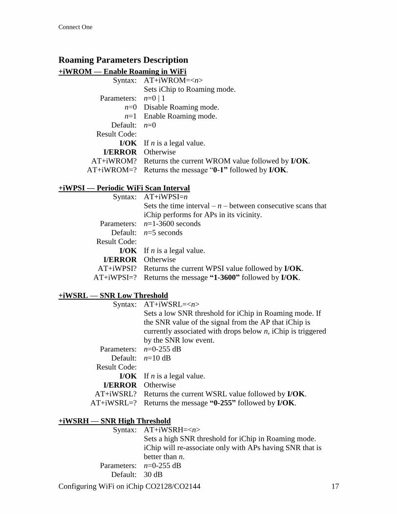
Roaming Parameters Description
+iWROM — Enable Roaming in WiFi
Syntax: AT+iWROM=<n>
Sets iChip to Roaming mode.
Parameters: n=0 | 1
n=0 Disable Roaming mode.
n=1 Enable Roaming mode.
Default: n=0
Result Code:
I/OK If n is a legal value.
I/ERROR Otherwise
AT+iWROM? Returns the current WROM value followed by I/OK.
AT+iWROM=? Returns the message ―0-1” followed by I/OK.
+iWPSI — Periodic WiFi Scan Interval
Syntax: AT+iWPSI=n
Sets the time interval – n – between consecutive scans that
iChip performs for APs in its vicinity.
Parameters: n=1-3600 seconds
Default: n=5 seconds
Result Code:
I/OK If n is a legal value.
I/ERROR Otherwise
AT+iWPSI? Returns the current WPSI value followed by I/OK.
AT+iWPSI=? Returns the message “1-3600” followed by I/OK.
+iWSRL — SNR Low Threshold
Syntax: AT+iWSRL=<n>
Sets a low SNR threshold for iChip in Roaming mode. If
the SNR value of the signal from the AP that iChip is
currently associated with drops below n, iChip is triggered
by the SNR low event.
Parameters: n=0-255 dB
Default: n=10 dB
Result Code:
I/OK If n is a legal value.
I/ERROR Otherwise
AT+iWSRL? Returns the current WSRL value followed by I/OK.
AT+iWSRL=? Returns the message “0-255” followed by I/OK.
+iWSRH — SNR High Threshold
Syntax: AT+iWSRH=<n>
Sets a high SNR threshold for iChip in Roaming mode.
iChip will re-associate only with APs having SNR that is
better than n.
Parameters: n=0-255 dB
Default: 30 dB

Connect One
Configuring WiFi on iChip CO2128/CO2144 18
Result Code:
I/OK If n is a legal value.
I/ERROR Otherwise
AT+iWSRH? Returns the current WSRH value followed by I/OK.
AT+iWSRH=? Returns the message “0-255” followed by I/OK.
Monitoring WiFi Performance in iChip’s Configuration Web Site
The iChip configuration Web site includes a page dedicated to WiFi status and
performance, The Web page is automatically refreshed every second.
Open iChip‘s Configuration Site and select the ―802.11b/g Status‖ Menu option:
Connect One
Configuring WiFi on iChip CO2128/CO2144 19
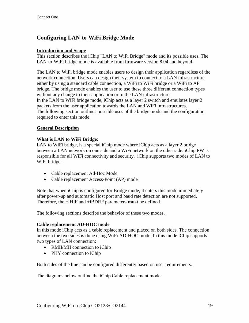
Configuring LAN-to-WiFi Bridge Mode
Introduction and Scope
This section describes the iChip "LAN to WiFi Bridge" mode and its possible uses. The
LAN-to-WiFi bridge mode is available from firmware version 8.04 and beyond.
The LAN to WiFi bridge mode enables users to design their application regardless of the
network connection. Users can design their system to connect to a LAN infrastructure
either by using a standard cable connection, a WiFi to WiFi bridge or a WiFi to AP
bridge. The bridge mode enables the user to use these three different connection types
without any change to their application or to the LAN infrastructure.
In the LAN to WiFi bridge mode, iChip acts as a layer 2 switch and emulates layer 2
packets from the user application towards the LAN and WiFi infrastructures.
The following section outlines possible uses of the bridge mode and the configuration
required to enter this mode.
General Description
What is LAN to WiFi Bridge:
LAN to WiFi bridge, is a special iChip mode where iChip acts as a layer 2 bridge
between a LAN network on one side and a WiFi network on the other side. iChip FW is
responsible for all WiFi connectivity and security. iChip supports two modes of LAN to
WiFi bridge:
Cable replacement Ad-Hoc Mode
Cable replacement Access-Point (AP) mode
Note that when iChip is configured for Bridge mode, it enters this mode immediately
after power-up and automatic Host port and baud rate detection are not supported.
Therefore, the +iHIF and +iBDRF parameters must be defined.
The following sections describe the behavior of these two modes.
Cable replacement AD-HOC mode
In this mode iChip acts as a cable replacement and placed on both sides. The connection
between the two sides is done using WiFi AD-HOC mode. In this mode iChip supports
two types of LAN connection:
RMII/MII connection to iChip
PHY connection to iChip
Both sides of the line can be configured differently based on user requirements.
The diagrams below outline the iChip Cable replacement mode:

Connect One
Configuring WiFi on iChip CO2128/CO2144 20
Drawing 1: Direct Cable connection (Original state)
Drawing 2: Cable replacement AD-HOC mode
In cable replacement AD-HOC mode, iChip supports two security layers. The first layer
is the Ad-Hoc WEP security and the second layer is MAC forwarding. When using MAC
forwarding the user can configure both iChips to forward packets to a predefined MAC
address as define in the MACF parameter. Without MAC forwarding, iChip will need to
broadcast outgoing packets. Broadcasting is slower than Unicasting and also has the
disadvantage of being received by all systems on a specific AD-Hoc network.
In this mode, all traffic from the LAN infrastructure is moved to the user application over
the WiFi AD-HOC connection and all traffic sent from the user application is moved
back to the LAN infrastructure.
To enter "Cable replacement Ad-Hoc mode" the following parameters should be used:
+iWLSI - Ad-Hoc network SSID (prefix with !)
+iWLCH - Ad-Hoc wireless channel
+iWST0 - WEP security type (64,128)
+iWKY0 - WEP security Key
Connect One
Configuring WiFi on iChip CO2128/CO2144 21
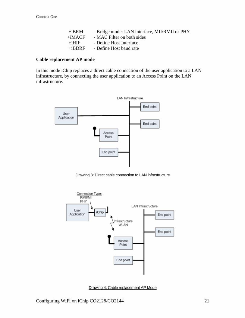
+iBRM - Bridge mode: LAN interface, MII/RMII or PHY
+iMACF - MAC Filter on both sides
+iHIF - Define Host Interface
+iBDRF - Define Host baud rate
Cable replacement AP mode
In this mode iChip replaces a direct cable connection of the user application to a LAN
infrastructure, by connecting the user application to an Access Point on the LAN
infrastructure.
Drawing 3: Direct cable connection to LAN infrastructure
Drawing 4: Cable replacement AP Mode
Connect One
Configuring WiFi on iChip CO2128/CO2144 22
In Cable replacement AP mode, iChip enables a user application to connect to an existing
AP on the LAN infrastructure. iChip connects to the AP using the same MAC address of
the user application which enables the LAN infrastructure to maintain that same
connection rules for the user application.
The following parameters should be used in order to set "Cable replacement AP mode"
(with WPA Security):
+iWLSI - WiFi network SSID
+iWST0 - WiFi security type
+iWLPP - WiFi WPA security Key
+iBRM - Bridge mode: LAN interface, MII/RMII or PHY
+iHIF - Define Host Interface
+iBDRF - Define Host baud rate
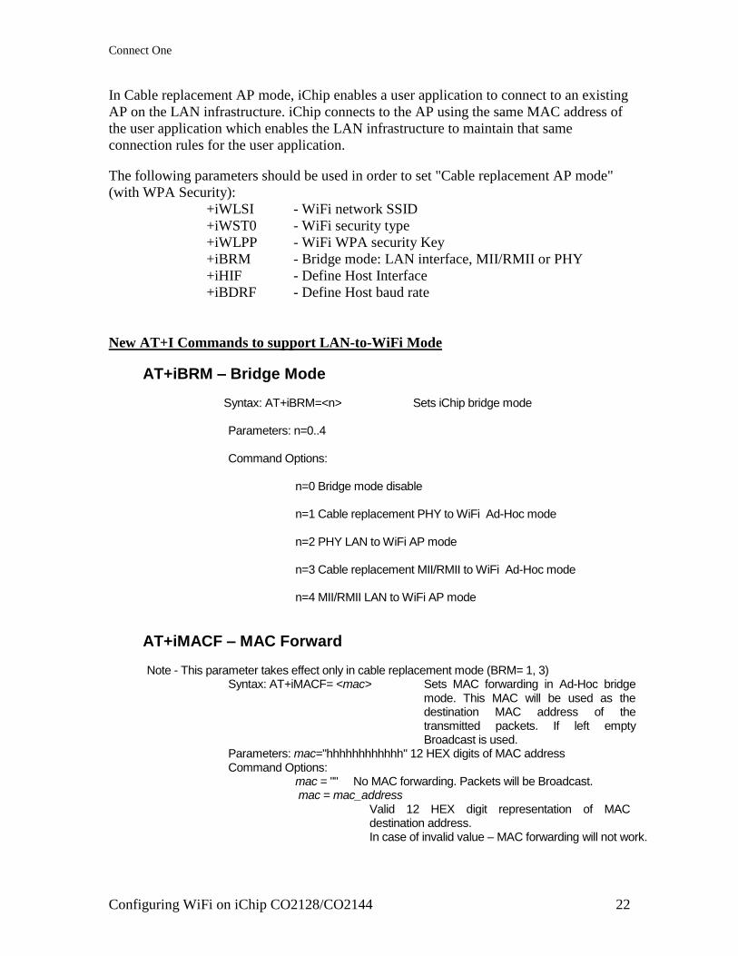
New AT+I Commands to support LAN-to-WiFi Mode
AT+iBRM – Bridge Mode
Syntax: AT+iBRM=<n> Sets iChip bridge mode Parameters: n=0..4 Command Options: n=0 Bridge mode disable n=1 Cable replacement PHY to WiFi Ad-Hoc mode n=2 PHY LAN to WiFi AP mode n=3 Cable replacement MII/RMII to WiFi Ad-Hoc mode n=4 MII/RMII LAN to WiFi AP mode
AT+iMACF – MAC Forward
Note - This parameter takes effect only in cable replacement mode (BRM= 1, 3) Syntax: AT+iMACF= <mac> Sets MAC forwarding in Ad-Hoc bridge
mode. This MAC will be used as the destination MAC address of the transmitted packets. If left empty Broadcast is used.
Parameters: mac="hhhhhhhhhhhh" 12 HEX digits of MAC address Command Options: mac = "" No MAC forwarding. Packets will be Broadcast. mac = mac_address Valid 12 HEX digit representation of MAC
destination address. In case of invalid value – MAC forwarding will not work.
International:
Connect One Ltd. 20 Atir Yeda Street Kfar Saba 44643, Israel Phone: +972-9-766-0456 Fax: +972-9-766-0461 Email: [email protected] http://www.connectone.com
USA: Connect One Semiconductors, Inc. 560 S. Winchester Blvd. Suite 500 San Jose, CA 95128 Tel: (408) 572-5675 Fax: (408) 572-5601
Pub. No. 20-1000-07, May 2011
Micro Access-Point (uAP) Mode
iChip Firmware versions 809 and above contain support for uAP mode. In this mode,
iChip‘s WiFi driver is configured as an Access-Point rather than a station. Changing
iChip‘s WiFi mode of operation requires a Firmware change. iChip‘s default Firmware
version, i.e. 809xxx, is traditionally in WiFi station mode. The parallel Firmware version
for uAP mode shall be labeled: 809xxxUAP. Most of iChip‘s WiFi parameters defined
originally for Station mode remain operational in uAP mode as well, possibly with some
additional variations. The following describes the parameters and modes relevant for uAP
mode.
Supported AP functionality
WEP encryption
Open system authentication
WEP shared key authentication
Embedded WPA/WPA2-PSK authenticator
IEEE power save
Hidden SSID feature
Aging of inactive client stations
Non-Configurable AP Parameter Settings
Beacon Period = 20 TU (1 TU = 1024 usec)
DTIM Period = 1 beacon period
Aging Timer = 0 (station will never be aged out)
Group ReKey timer = 0 (group key will never be aged out)
Pairwise key handshake timeout = 650 ms (relevant only if security is WPA or
WPA2)
Pairwise key retries count = 10 (relevant only if security is WPA or WPA2)
Group key handshake timeout = 650 ms (relevant only if security is WPA or
WPA2)
Group key retries count = 10 (relevant only if security is WPA or WPA2)
PS (of the uAP unit) is disabled!
Max TX rate = 54 Mbps Data rate to use for unicast packets transmission.
TX power level = 13 dBm Power level that the AP will use for transmitting packets
to client stations in the BSS.
Broadcast SSID = Enabled AP responds to probe requests from client stations that
contain null SSID. AP Generates beacons that contain its
SSID.
Packet forwarding = 1 AP handles intra-BSS packets
Max Stations count = 8 Range: 0-8
Retry Limit = 7 Retry limit to use for packet transmissions. Range: 0-14
Connect One
Configuring WiFi on iChip CO2128/CO2144 24
RSN replay attack protection = Disabled If enabled, the frames detected as replay frames will be
dropped.
Configurable iChip Parameters used in AP mode
+iWLCH – Sets the AP channel. Default value is 6.
+iWLSI – Sets the AP SSID. Default value is "Connect One uAP"
+iWST0 – Sets the AP security type, where:
o n=0 – no security
o n=100 – WPA-PSK TKIP + WPA2-PSK CCMP (auto mode)
o n=1 – WEP64 open authentication
o n=2 – WEP128 open authentication
o n=101 – WEP64 shared authentication
o n=102 – WEP128 shared authentication
o n=3 – WPA-PSK TKIP
o n=103 – WPA-PSK TKIP + CCMP
o n=4 – WPA2-PSK CCMP
o n=104 – WPA2-PSK TKIP + CCMP
+iWLPP – Sets the AP WPA/WPA2 Pass Phrase
+iWLK1 – Sets the AP WEP key
iChip AT+i Commands used in relation to uAP mode
AT+iRP30 – displays a list of connected clients. The list contains client MAC
address, IP address, Power status (active/power save) and client
host name. For example: AT+iRP30
MAC Address Power Status RSSI IP Address Host Name
001DD934C1EE power save 203 192.168.0.2 PCdesk1
I/OK
AT+iWRFD – Fully stops the AP. iChip de-authenticates all clients, stops
sending beacons and turns the radio OFF.
AT+iWRFU – Restart AP. iChip turns radio ON and resumes sending beacons.
AT+iRP10, AT+iRP11 and AT+iRP20 These report commands are not relevant in uAP FW, hence, the
return value shall be I/ERROR (067).