Embed Size (px)
Citation preview

Why Use FEA?
An introduction to
Finite Element Analysis
www.caliberdesign.co.nz HO
W T
O G
UID
E

Introduction
This is a How To Guide for product developers and their
managers. It explains Finite Element Analysis (FEA) in
plain language: What is it? Why use it? What are the
benefits for product development and for business?
With FEA, basically you can road test your design before
going anywhere near a production facility. Do these parts
fit together? What impact will freezing temperatures have
on this part? How will my design handle intense vibration?
Questions like this can be answered, and your design
tweaked and re-tested—all virtually! This way, the
expensive process of physical prototyping is only done
when you have confidence in your design.
Adding FEA to your product development process will
invariably result in quicker development times, reduced
development costs, and a more robust and reliable
product … all good
for the bottom line!
If you’d like to
discuss how FEA
could benefit your
project and bottom
line, please get in
touch!
Finite Element Analysis (FEA) is a method of analysing how
a part or assembly will perform over its lifetime. FEA
enables you to predict potential design issues and
therefore minimise risk to your product, profits, and your
business.
With FEA you can test the impact of varying conditions (stress, vibration,
buckling, fatigue, creep, heat, etc) on your design. It is a powerful
simulation tool used alongside the likes of CFD (computational fluid
dynamics) and motion analysis.
By including FEA as part of your product development process, you can
simulate the effects that real world extremes will have on your design
before you’ve created a physical prototype. This virtual prototyping saves
you substantial time and cost by minimising the number of physical
prototypes required.
These days FEA is being used in virtually every engineering discipline:
aerospace, automotive, biomedical, chemicals, electronics, energy,
geotechnical, manufacturing, and plastics industries all routinely apply
Finite Element Analysis.
Some common FEA packages include Cosmos, SolidWorks Simulation,
Femap, Nastran, Ansys, and Abaqus.
What is FEA?
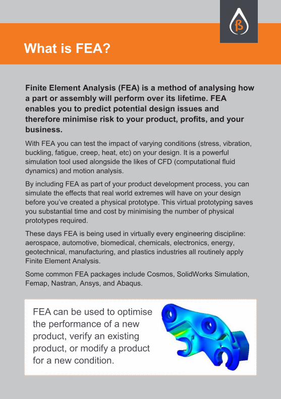
FEA can be used to optimise
the performance of a new
product, verify an existing
product, or modify a product
for a new condition.
What would it be worth to your business if you could predict
potential failures prior to getting your product to market?
How would that affect consumer perception of your product?
How would less warranty claims affect your cash flow?
What if you could halve or even quarter your prototype and
testing costs? How much quicker could you get to market?
What impact would that have on your bottom line?
Would it be helpful for you to know if your structure or product
can withstand working loadings? Will permanent deformation
occur? Will buckling or vibrations ever be a problem?
Can material be reduced to save costs?
What are the benefits of FEA?
FEA is a crucial step that you can easily add to your development
program. It will save you time and money by highlighting problems
and finding solutions during your product design phase, before any
material is ordered or before you even contemplate ‘cutting steel’!
FEA can also be used to:
check your design is on track during the design process.
check calculations, when hand calculations are too difficult.
optimise stress, mass, heat, etc to get the best results before the
manufacturing stage of the project.
understand structural behaviour and
therefore remove uncertainty in the
design phase.

There are many different types of analysis supported by the finite
element method. Below is an explanation of the main types of FEA
and their applications:
LINEAR OR NON-LINEAR
All analyses can be classed as being linear or non-linear. Whenever the
‘initial conditions’ change during an analysis, non-linearity exists.
Imagine you are blowing up a balloon; as the balloon fills its diameter
rapidly changes. The balloon material stretches significantly, becoming
thinner and stiffer. Hence the effort required to inflate the balloon changes
as it is inflated. A non-linear analysis can take this into account while a
linear analysis cannot.
Linear analysis have the ability to be directly ‘scaled’ … for example, if the
load is doubled then the results (stress, deflection, etc) will simply double.
The use of this knowledge can significantly reduce the number of FEA
analyses that need to be undertaken.
STATIC OR DYNAMIC
Are the loads applied slowly or fast? (Like snow loading on a roof or a
cellphone dropping to the ground?) When loads vary rapidly with respect
to time, the mass and stiffness of the structure start to have an influence
on the results. Using the example of a cell phone dropping; the heavier the
phone is, the greater the structure needed to support it.
COMPARATIVE OR ABSOLUTE
Does the analysis need to provide ‘accurate’ results or is a percentage
change all that is required? You may have an existing successful product
with uncertain loading conditions that you would like to change. For
example, it might be a coil spring from a car suspension. Without knowing
anything about the load that the spring undergoes on the car, with a
comparative analysis it may be possible to see whether design changes to
the geometry (for example) are going to improve or reduce the
performance of the unit.
FEA types & applications
There are many subtypes of FEA. These are explained below:
Vibration and Impact: These are types of dynamic analysis that
can be used to assess how a product will perform. For example, will the
car steering wheel vibrate while driving? Would my product survive a
drop onto floor from one metre up?
Buckling: A length of wire can hold much less load in compression
compared to tension due to a phenomenon called ‘buckling’. It can
occur in any object that is relatively thin/narrow in one direction, such as
beams and sheet-metal parts. FEA can be used to predict the load at
which an object will partially or fully buckle.
Contact: This non-linear technique analyses the effect of parts
contacting each other. For example, a car crashing into a flexible safety
barrier or a bolted ‘friction-grip’ joint.
Fatigue: FEA is a powerful tool for assessing the complex effects
of cyclic loading (fatigue) on components. A product life can be
estimated in years and areas likely to crack
highlighted.
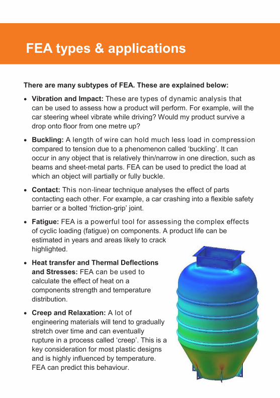
Heat transfer and Thermal Deflections
and Stresses: FEA can be used to
calculate the effect of heat on a
components strength and temperature
distribution.
Creep and Relaxation: A lot of
engineering materials will tend to gradually
stretch over time and can eventually
rupture in a process called ‘creep’. This is a
key consideration for most plastic designs
and is highly influenced by temperature.
FEA can predict this behaviour.
FEA types & applications

Talking to an FEA expert is the best place to start!
Static studies are cost effective and acceptable for most general
engineering scenarios. Structural, vibration, fatigue, heat, flow, etc are
common types of analyses that can be run.
Non-linear studies are more complicated and expensive to
perform. If you are looking for analysis of deforming structures,
complicated contact conditions, creep etc, then you may need to take
this route.
Solids, shells and beams are all mesh (or element) options in a
general FEA package. In general, beams should be used for frames
and section structures, shells for sheet metal components, and solids
for complicated geometry.
All options have their pros and cons as well as limitations, so make sure
your analyst is competent and has done their research!
How does FEA software work?
Knowing exactly how FEA software works can be confusing,
but the basic workflow is as follows:
1. Create geometric model
2. Define finite element model (create mesh with FEA software)
3. Define operating environment (apply forces, constraints, etc)
4. Compute structural response (stress, deflection, temperatures,
etc)
5. Review and interpret the results
6. Re-design as necessary and repeat until satisfied
What type is best for me?
In order to incorporate FEA into your design, you need to have:
A GOAL – What are you wanting to achieve (improved strength,
reduced mass, etc)? If your goals aren’t clear then the FEA process
is pointless!
GEOMETRY – Models or dimensions of your design and material
properties as appropriate.
CONSTRAINTS – A good understanding of how the system is
interacting with its surroundings (is it bolted, welded, sliding, etc).
LOADS – What are the magnitudes and how are they to be applied?
RISK ASSESSMENT – What risks are associated with this product?
How important is it to get the design right?
AN ANALYST – An experienced analyst can develop realistic loads
and constraints. They are also more likely to give you results you can
rely on.
What do I need to know?
What do the plots mean?
Understanding results means not only looking at the result
plots, but also reading the analysis report (if you have one).
It is easy to create a result, but takes skill and
understanding to create a result that is accurate.
Check that the constraints and forces make sense, read the
assumptions, check the hand calculations, and then decide
whether the conclusions are representative of reality.

It’s easy to create a stress plot and put it into a report. But is it right?
Engineering calculations should never be neglected! Validate your
FEA results to make sure they are correct!
Applying constraints and forces differently can cause wildly varying
results. You need to look past the final plot and think about whether the
conditions applied to the model are accurately representing the real
world scenario.
A good analyst knows how and why they are setting up the FEA
analysis. Experience and engineering judgement are the most important
factors for creating the most accurate analysis.
Physical testing is a great way to check your boundary conditions and
results!
If you have your analyst increase the deformation scale 100x, does the
deformed shape look as expected?
Are the results correct ENOUGH?
Picture you are the manufacturer of mid range, low production run mountain
bikes. You want to asses whether a small design change to an existing,
successful product is going to increase or decrease the durability of the design.
In this case, it may be appropriate to run a quick comparative analysis with some
representative design loads.
If the new design is weaker than the current design, you may choose to avoid
the design change or to tweak the design to improve its strength, regardless of
whether the analysis is providing ‘exact’ results or not.
In a different scenario … you might manufacture bespoke high-value racing
bikes for Olympic competition. In this case, a failure could both injure the athlete
and significantly damage your brand, it may be prudent to analyse the bike in
great detail . The challenge is to:
1. Avoid ‘paralysis by analysis’
2. Get the ‘level’ of analysis correct. What corresponding level of risk are you
prepared to accept?
Are the results correct?
What are the common traps?
FEA has played an important role in the design and analysis
of mechanical products for decades, however it has been
prohibitively expensive. Now that FEA tools are
incorporated into the best CAD software, it is a much more
affordable and accessible option.
Here are some other common traps:
Thinking the answer is right before checking the scale is the easiest
trap to fall into!
Incorrect restraints are easy to apply and can significantly change the
final result. Also, view results near restraints with caution as it takes an
experienced analyst to get valid results in these areas.
A coarse mesh is a very easy way to understate your stresses whilst an
overly fine mesh may take days to solve. Making sure the mesh is
appropriate for your model is a skill that comes with training and
experience.
Bad assumptions can mean the analysis is doomed from the start.
Make sure that the research has been done and the assumptions
make sense. If the analyst wasn’t given the full story, they might be
assuming something completely wrong with the setup.
FEA is not a substitute for final physical testing. It should be used to
minimise testing required, reduce development costs, and accelerate
time to market!
We must caution you: FEA must be used with care. FEA
produces fantastic colour plots and it can be difficult to notice
that you have made a mistake. It becomes a case of rubbish
in=rubbish2 out.
FEA is a crucial step that you can easily add to your
development program. It will save you significant time and money
by highlighting problems and finding solutions during your
product design phase, before any material is ordered or before
you even contemplate ‘cutting steel’!
Here are some key points to remember about FEA:
Engineers use FEA to simulate how a product will respond to expected
loading conditions in real world situations.
If you are designing a new product, you should consider how to embed
FEA into your design cycle.
With FEA, you can test your design for stress, vibration, buckling,
fatigue, and heat BEFORE prototyping.
There are many types of FEA. Which type to choose depends on your
product, the materials involved, how it will be made, and how it will be
used.
If you have decided you want an FEA done on your design, make sure
you approach an experienced analyst and be clear about what you
want to achieve. A goal is essential.
Rubbish in = Rubbish2 out. Don’t let the pretty pictures fool you. FEA
results are easily misinterpreted and should be backed up with hand
calculations and physical testing.
The software may have got cheaper but the skill required to do an
accurate and reliable FEA hasn’t changed. Career analysts are few and
far between, but worth their weight in gold.
Quick Summary
Get it right before you cut steel!

Caliber Design | 97 Cook Street, Auckland 1010
E [email protected] | P +64 9 379 7357
www.caliberdesign.co.nz
This How To Guide is written for product
developers and their managers.
It explains Finite Element Analysis (FEA)
in plain language:
What is it?
Why use it?
What are the benefits for product
development and for business?
© Caliber Design Ltd. All rights reserved.